This is a modern-English version of A Course In Wood Turning, originally written by Milton, Archie Seldon, Wohlers, Otto K..
It has been thoroughly updated, including changes to sentence structure, words, spelling,
and grammar—to ensure clarity for contemporary readers, while preserving the original spirit and nuance. If
you click on a paragraph, you will see the original text that we modified, and you can toggle between the two versions.
Scroll to the bottom of this page and you will find a free ePUB download link for this book.
Transcribers note: Mis-spelled words in the original left as is. Below is a list of all known mis-spelled words kept from the original:
Transcriber's note: Misspelled words in the original are left unchanged. Below is a list of all known misspelled words taken from the original:
Table Of Contents - Classification of Plates
bowels - should be bowls
Chapter II - SPEED OF THE LATHE
centrificial - should be centrifugal
Chapter IX - METHODS OF FASTENING STOCK
epecially - should be especially
Chapter XI - SPIRAL TURNING
modelling - should be modeling
Chapter XI - PLATES B-V--2-b, b’
midde - should be middle
Table Of Contents - Classification of Plates
bowels - should be bowls
Chapter II - SPEED OF THE LATHE
centrifugal
Chapter IX - METHODS OF FASTENING STOCK
especially
Chapter XI - SPIRAL TURNING
modeling
Chapter XI - PLATES B-V--2-b, b’
middle
A COURSE IN WOOD TURNING
By ARCHIE S. MILTON
OTTO K. WOHLERS
")
THE BRUCE PUBLISHING COMPANY
MILWAUKEE, WISCONSIN
1919
PREFACE
This book is the outgrowth of problems given to high school pupils by the writers, and has been compiled in logical sequence. Stress is laid upon the proper use of tools, and the problems are presented in such a way that each exercise, or project, depends somewhat on the one preceding. It is not the idea of the writers that all problems shown should be made, but that the instructor select only such as will give the pupils enough preliminary work in the use of the tools to prepare them for other models following.
This book comes from the challenges given to high school students by the authors and has been organized in a logical order. Emphasis is placed on the correct use of tools, and the problems are presented so that each exercise or project builds on the previous one. The authors don’t intend for every problem shown to be completed, but rather for the instructor to choose only those that provide students with enough foundational practice in using the tools to prepare them for subsequent models.
The related matter on the care of the lathe and tools, the grinding of chisels, the polishing of projects, and the specific directions and cautions for working out the various exercises and projects with the drawings, make the book not only valuable for reference, but also as a class text to be studied in connection with the making of projects. The drawings show exact dimensions and are tabulated in the upper right-hand corner in such a way that they may be used in a filing case if desired. At least two designs are shown for each model, and these may be used as suggestions from which students, with the aid of the instructor, may work out their own designs.
The information on taking care of the lathe and tools, sharpening chisels, polishing projects, and the specific instructions and precautions for completing various exercises and projects using the drawings makes this book not only a great reference but also a useful text for learning alongside project work. The drawings provide exact dimensions and are organized in the upper right corner so they can be stored in a filing case if needed. At least two designs are provided for each model, which can be used as inspiration for students to develop their own designs with the help of the instructor.
The book has been divided into two parts: (A) Spindle Turning, and (B) Face-Plate Turning. The same order is followed in each part; the related information is supplied where required as the pupil progresses.
The book is divided into two parts: (A) Spindle Turning and (B) Face-Plate Turning. The same order is maintained in each part; relevant information is provided as the learner advances.
Part A takes up the following: (I) Exercises; (II) Models, involving the same tool processes, only in a somewhat different degree; (III) Oval Turning, explaining the use of two centers; (IV) Duplicate Turning, where identical pieces are turned.
Part A covers the following: (I) Exercises; (II) Models, which involve the same tool processes but to a slightly different extent; (III) Oval Turning, detailing the use of two centers; (IV) Duplicate Turning, where identical pieces are turned.
Part B is arranged as follows: (I) Exercises; (II) Models, which are an application of cuts in exercises that involve only face-plate work; (III) Models, which require chucking; (IV) Assembling Exercises, involving spindle turning, face-plate work and chucking; (V) Spiral Turning, showing the method of turning a spiral on the lathe.
Part B is organized as follows: (I) Exercises; (II) Models, which apply cuts in exercises that involve only face-plate work; (III) Models that require chucking; (IV) Assembling Exercises, involving spindle turning, face-plate work, and chucking; (V) Spiral Turning, demonstrating how to turn a spiral on the lathe.
The ultimate aim of this book is to give, through the exercises and problems, a thorough understanding of the principles of wood turning by gradually developing the confidence of the pupil in the complete control of his tools, at the same time suggesting harmonious lines in design which will lead to other ideas in designing problems.
The main goal of this book is to provide a comprehensive understanding of wood turning principles through various exercises and problems. It aims to help students build their confidence in fully mastering their tools while also offering suggestions for harmonious design lines that can inspire new ideas for design challenges.
TABLE OF CONTENTS
| Pages |
|
| CHAPTER I Introductory Intro --Commercial and Educational Values of Wood Turning --Commercial and Educational Benefits of Wood Turning --Elements of Success Keys to Success |
9-10 |
| CHAPTER II The Lathe The Lathe --Care of the Lathe Lathe Maintenance --Speed of the Lathe Lathe speed --Method of Figuring the Diameter of Pulleys --How to Determine the Diameter of Pulleys --Rules for Finding the Speeds and Sizes of Pulleys --Guidelines for Determining the Speeds and Sizes of Pulleys --Points on Setting Up the Lathe and Shafting --Tips for Setting Up the Lathe and Shafting |
11-14 |
| CHAPTER III Wood Turning Tools Woodworking Lathe Tools --Grinding and Whetting Turning Tools Sharpening and honing tools --The Gouge The Cut --The Parting Tool The Separation Tool --Scraping Tools Web Scraping Tools |
15-18 |
| CHAPTER IV Spindle Turning Lathe Turning --Centering Stock Centering Inventory --Clamping Stock in the Lathe Securing Stock in the Lathe --Adjusting the Tool Rest --Adjusting the Tool Support --Position of the Operator at the Lathe --Operator's Position at the Lathe --Holding the Tools --Holding the Tools --Use of the Tools in Spindle Turning --Using the Tools in Spindle Turning |
19-21 |
| CHAPTER V Tool Processes in Spindle Turning Tool Processes in CNC Turning --The Roughing Cut The Roughing Cut --The Sizing Cut The Size Cut --The Smoothing Cut The Smoothing Cut --Testing for Smoothness --Testing for Smoothness --Measuring for Length --Measuring Length --Squaring Ends --Square Ends --Cutting Off --Cutting Off --Shoulder Cuts Shoulder Cuts --Taper Cuts Tapered Haircuts --V Cuts-Concave Cuts V Cuts - Concave Cuts --Convex Cuts Curved Cuts --Combination Cuts Combo Cuts --Chisel Handles Chisel grips --Mallets and Handles Mallets & Handles --Vise Handles Vise grips |
22-32 |
| CHAPTER VI Oval Turning Oval Turning --Tool Operations --Tool Usage |
33-34 |
| CHAPTER VII Duplicate Turning Duplicate Rotation --Use of Measuring Stick Using a Ruler --Use of Templets Using templates |
35 |
| CHAPTER VIII Finishing and Polishing Finishing and Polishing --Ordinary Cabinet Finishing Standard Cabinet Finishing --French Polishing French polishing --Method of Applying French Polish How to Apply French Polish |
36-38 |
| CHAPTER IX Face-Plate and Chuck Turning Faceplate and chuck turning --Methods of Fastening Stock Ways to Secure Stock --Small Single Screw Face-Plate Small Single Screw Faceplate --Large Surface Screw Face-Plate Large Surface Screw Faceplate --Gluing to Waste Stock Gluing to Scrap Material --Lathe Adjustments Lathe Settings --Position of Tool Rest Tool Rest Position |
39-40 |
| CHAPTER X Tool Processes in Face-Plate and Chuck Turning Tool Processes in Faceplate and Chuck Turning --Straight Cuts Straight Cuts --Roughing Off Corners Smoothing Corners --Calipering for Diameter Measuring Diameter --Smoothing Cut Smoothing Trim --Roughing Cut on the Face Face Roughing Cut --Smoothing the Face Smoothing the Face --Laying Off Measurements Measuring Layoffs --External Shoulders External Shoulders --Internal Shoulders Internal Shoulders --Taper Cuts Tapered Cuts --V Cuts V-Cuts --Concave Cuts Concave Cuts --Convex Cuts Curved Cuts --Combination Cuts Combo Cuts --Use of Scraping Tools Using Scraping Tools --Internal Boring Internal Boredom --Turning a Sphere --Rotating a Sphere |
41-48 |
| CHAPTER XI Spiral Turning Spiral Turning --Single Spiral, Straight Shaft Single Spiral, Straight Shaft --Tapered Shaft Tapered Shaft --Double Spiral, Tapered Shaft Double spiral, tapered shaft --Double Spiral, Straight Shaft Double Spiral, Straight Shaft --Double Groove Spiral, Straight Shaft Double Groove Spiral, Straight Shaft |
49-55 |
PLATES--SPINDLE TURNING.
| Straight Cuts | 57 |
| Shoulder Cuts | 59-65 |
| Taper Cuts | 67-77 |
| V Cuts | 79-81 |
| Concave Cuts | 83-87 |
| Convex Cuts | 89-95 |
| Combination Cuts | 97-101 |
| Chisel Handles | 103-107 |
| Cabinet File Handle | 109 |
| Scratch Awl Handle | 111 |
| Carving Tool Handle | 113 |
| Turning Chisel Handle | 115 |
| Mallets | 117-119 |
| Gavels | 121-127 |
| Darning Eggs | 129-133 |
| Stocking Darner | 131 |
| Potato Masher | 135 |
| Rolling Pins | 139-141 |
| Vise Handle | 143 |
| Screw Driver Handles | 145-147 |
| Pene Hammer Handle | 149 |
| Claw Hammer Handle | 151 |
| Indian Clubs | 153-155 |
| Dumb Bells | 157-159 |
| Ten Pins | 161 |
| Drawer Pulls | 163-165 |
PLATES--CHUCK TURNING.
| Straight Cuts | 167-169 |
| Shoulder Cuts | 171-173 |
| Taper Cuts | 175-177 |
| V Cuts | 179-181 |
| Concave Cuts | 183-185 |
| Convex Cuts | 187-189 |
| Combination Cuts | 191-195 |
| Match Boxes | 197-201 |
| Pin Trays | 203-205 |
| Hair Pin Receivers | 207-209 |
| Hat Pin Receivers | 211-213 |
| Ornamental Vases | 215-219 |
| Spinnet | 221 |
| Towel Rings | 223-227 |
| Card Trays | 229-235 |
| Picture Frames | 237-243 |
| Nut Bowls | 245-251 |
| Napkin Rings | 253-257 |
| Jewel Boxes | 259-273 |
| Collar Boxes | 275-279 |
| Sphere | 281 |
| Checker Men | 283 |
| Candle Sticks | 285-293 |
| Shaving Stands | 295-301 |
| Reading Lamp Stands | 303-307 |
| Pedestal | 309 |
| Smokers' Stands | 311-313 |
| Pin Cushion and Spoon Holder | 315 |
| Chess Men | 317-319 |
| Pedestals | 321-325 |
| Electric Reading Lamps | 327-335 |
| Magazine Holders | 337-339 |
CLASSIFICATION OF PLATES
|
1. Straight Cuts, a Straight Cuts, __A_TAG_PLACEHOLDER_0__ 2. Shoulder Cuts, __A_TAG_PLACEHOLDER_0__-__A_TAG_PLACEHOLDER_1__-__A_TAG_PLACEHOLDER_2__-__A_TAG_PLACEHOLDER_3__ Taper Cuts, __A_TAG_PLACEHOLDER_0__-__A_TAG_PLACEHOLDER_1__-__A_TAG_PLACEHOLDER_2__-__A_TAG_PLACEHOLDER_3__-__A_TAG_PLACEHOLDER_4__-__A_TAG_PLACEHOLDER_5__ 5. Concave Cuts, __A_TAG_PLACEHOLDER_0__-__A_TAG_PLACEHOLDER_1__-__A_TAG_PLACEHOLDER_2__ 6. Convex Cuts, __A_TAG_PLACEHOLDER_0__-__A_TAG_PLACEHOLDER_1__-__A_TAG_PLACEHOLDER_2__-__A_TAG_PLACEHOLDER_3__ 7. Combo Cuts, __A_TAG_PLACEHOLDER_0__-__A_TAG_PLACEHOLDER_1__-__A_TAG_PLACEHOLDER_2__ Chisel Handles, __A_TAG_PLACEHOLDER_0__-__A_TAG_PLACEHOLDER_1__-__A_TAG_PLACEHOLDER_2__ Cabinet File Handle, d Cabinet File Handle, __A_TAG_PLACEHOLDER_0__ Scratch Awl Handle, e Scratch Awl Handle, __A_TAG_PLACEHOLDER_0__ Carving Tool Handle, f Carving Tool Grip, __A_TAG_PLACEHOLDER_0__ Turning Chisel Handle, g Chisel Handle Adjustment, __A_TAG_PLACEHOLDER_0__ Gavels, __A_TAG_PLACEHOLDER_0__-__A_TAG_PLACEHOLDER_1__-__A_TAG_PLACEHOLDER_2__-__A_TAG_PLACEHOLDER_3__ Darning Egg, c Darning egg, __A_TAG_PLACEHOLDER_0__ 7. Vise Handles, a Vise Handles, __A_TAG_PLACEHOLDER_0__ Penne Hammer Handle, a Penne Hammer Handle, __A_TAG_PLACEHOLDER_0__ Claw Hammer Handle, b Claw Hammer Grip, __A_TAG_PLACEHOLDER_0__ 3. Tenpins, a 3. Bowling, __A_TAG_PLACEHOLDER_0__ 7. Combo Cuts, __A_TAG_PLACEHOLDER_0__-__A_TAG_PLACEHOLDER_1__-__A_TAG_PLACEHOLDER_2__ Match Boxes, __A_TAG_PLACEHOLDER_0__-__A_TAG_PLACEHOLDER_1__-__A_TAG_PLACEHOLDER_2__ 5. Decorative Vases, __A_TAG_PLACEHOLDER_0__-__A_TAG_PLACEHOLDER_1__-__A_TAG_PLACEHOLDER_2__ 6. Spinnet, (game) a 6. Spinnet, (game) __A_TAG_PLACEHOLDER_0__ Towel Rings, __A_TAG_PLACEHOLDER_0__-__A_TAG_PLACEHOLDER_1__-__A_TAG_PLACEHOLDER_2__ 2. Card Trays, __A_TAG_PLACEHOLDER_0__-__A_TAG_PLACEHOLDER_1__-__A_TAG_PLACEHOLDER_2__-__A_TAG_PLACEHOLDER_3__ 3. Picture Frames, __A_TAG_PLACEHOLDER_0__-__A_TAG_PLACEHOLDER_1__-__A_TAG_PLACEHOLDER_2__-__A_TAG_PLACEHOLDER_3__ 4. Nut Bowels, __A_TAG_PLACEHOLDER_0__-__A_TAG_PLACEHOLDER_1__-__A_TAG_PLACEHOLDER_2__-__A_TAG_PLACEHOLDER_3__ 5. Napkin Rings, __A_TAG_PLACEHOLDER_0__-__A_TAG_PLACEHOLDER_1__-__A_TAG_PLACEHOLDER_2__ Jewel Boxes, __A_TAG_PLACEHOLDER_0__-__A_TAG_PLACEHOLDER_1__-__A_TAG_PLACEHOLDER_2__-__A_TAG_PLACEHOLDER_3__-__A_TAG_PLACEHOLDER_4__-__A_TAG_PLACEHOLDER_5__-__A_TAG_PLACEHOLDER_6__-__A_TAG_PLACEHOLDER_7__ 7. Collar Boxes, __A_TAG_PLACEHOLDER_0__-__A_TAG_PLACEHOLDER_1__-__A_TAG_PLACEHOLDER_2__ 8. Spheres, a 8. Areas, __A_TAG_PLACEHOLDER_0__ 9. Checker Men, a 9. Checkers, __A_TAG_PLACEHOLDER_0__ Candle Sticks, __A_TAG_PLACEHOLDER_0__-__A_TAG_PLACEHOLDER_1__-__A_TAG_PLACEHOLDER_2__-__A_TAG_PLACEHOLDER_3__-__A_TAG_PLACEHOLDER_4__ 2. Shaving Stands, __A_TAG_PLACEHOLDER_0__-__A_TAG_PLACEHOLDER_1__-__A_TAG_PLACEHOLDER_2__-__A_TAG_PLACEHOLDER_3__ 3. Reading Lamp Stands, __A_TAG_PLACEHOLDER_0__-__A_TAG_PLACEHOLDER_1__-__A_TAG_PLACEHOLDER_2__ 4. Pedestals, a 4. Pedestals, __A_TAG_PLACEHOLDER_0__ 6. Pin Cushions and Spool Holder, a 1. Pedestal, (Single) __A_TAG_PLACEHOLDER_0__-__A_TAG_PLACEHOLDER_1__, (Double) __A_TAG_PLACEHOLDER_2__ 2. Reading Lamps, (Single) __A_TAG_PLACEHOLDER_0__-__A_TAG_PLACEHOLDER_1__-__A_TAG_PLACEHOLDER_2__ (Double) __A_TAG_PLACEHOLDER_3__-__A_TAG_PLACEHOLDER_4__ |
CHAPTER I
INTRODUCTORY
WELCOME
Wood turning has had a definite place in the commercial world for a great many years. It is used in various forms in making furniture and furniture parts, building trim, tool parts, toys, athletic paraphernalia and many other useful and beautiful articles in common use.
Wood turning has been an important part of the commercial world for many years. It's used in different ways to create furniture and furniture parts, building trim, tool components, toys, sports equipment, and many other useful and attractive items that people use every day.
When properly taught in the schools it is one of the most valuable types of instruction. It appeals to pupils more than any other type of manual work, as it embodies both the play and work elements. It is very interesting and fascinating and, in the hands of a skilled instructor, is readily correlated with other work.
When taught correctly in schools, it is one of the most valuable forms of instruction. Students are more drawn to it than any other type of hands-on activity because it combines both play and work. It's very engaging and captivating, and with a skilled teacher, it easily connects with other subjects.
Wood turning gives a pupil preliminary experience necessary in pattern making and machine shop work. It brings into play the scientific element by demonstrating the laws governing revolving bodies. In bringing the chisel into contact with the revolving surface, the mathematical principle of the "point of tangency" is illustrated. Excellent tool technique is developed in wood turning as on the exactness of every movement depends the success of the operator, and any slight variation will spoil a piece of work. This brings in a very close correlation of the mental and motor activities and also gives the student an opportunity for observing and thinking while at work. When his tool makes a "run" he must determine the reason and figure out why a certain result is obtained when the chisel is held in a given position. Certain cuts must be fully mastered, and it takes a good deal of experience and absolute confidence in one's self in manipulating the tools before it is possible to attempt skilful work. If scraping is allowed the educational value of the work is lost.
Wood turning gives students essential experience needed for pattern making and machine shop tasks. It incorporates scientific principles by showcasing the laws governing rotating objects. When the chisel interacts with the spinning surface, the mathematical concept of the "point of tangency" is demonstrated. Excellent tool skills are developed in wood turning, as the success of the operator relies on the precision of each movement; even a slight mistake can ruin a project. This creates a strong connection between mental and physical activities and allows students to observe and think while working. When their tool goes off course, they must identify the cause and understand why a specific outcome occurs when the chisel is positioned a certain way. Certain cuts need to be mastered completely, requiring significant practice and total confidence in wielding the tools before attempting skilled work. If scraping is permitted, the educational value of the work is diminished.
In wood turning a vast field for design and modeling is opened, and art and architecture can be correlated. The pupil will see for himself the need of variety in curves and must use his judgment in determining curves that are so harmonious and pleasing that they will blend together. If properly taught the beauty in the orders of architecture can be brought out in the making of the bead, fillet, scotia, cove, etc.
In wood turning, a huge opportunity for design and modeling emerges, allowing art and architecture to connect. The student will recognize the necessity for variety in curves and must exercise their judgment in selecting curves that are harmonious and visually pleasing, ensuring they blend well together. If taught correctly, the beauty found in architectural styles can be highlighted in creating elements like the bead, fillet, scotia, cove, and more.
A feeling of importance is excited in a boy when he sees his hands shaping materials into objects of pleasing form. Wood turning properly taught awakens the aesthetic sense and creates a desire for the beautiful. The boy or man who has learned to make graceful curves and clean-cut fillets and beads will never be satisfied with clumsy effects which are characteristic in cheap commercial work, made only to sell.
A boy feels a sense of pride when he sees his hands transforming materials into attractive objects. Learning woodturning the right way sharpens his appreciation for beauty and sparks a desire for aesthetics. A boy or man who has mastered creating elegant curves and clean lines will never settle for the awkward results typical of cheap commercial products, which are made solely to sell.
Success in turning depends on the following:
Success in turning relies on the following:
1. Care of lathe, tools, selection of materials.
2. Study of the scientific elements of--
a. Revolving bodies.
b. Points of tangency.
c. Study of results by reasoning and observing.
3. Development of technique and exactness.
4. Correlation of mental and motor activities.
1. Maintenance of the lathe, tools, and selection of materials.
2. Exploration of the scientific aspects of--
Spinning objects.
b. Contact points.
c. Analyzing outcomes through reasoning and observation.
3. Enhancing technique and accuracy.
4. The link between mental and physical activities.
CHAPTER II
THE LATHE
THE LATHE
The sizes of turning lathes are given as 10", 12", etc. These figures denote the diameter, or size, of the largest piece of work that can be turned on them. The measurement is taken from the center point of the live center to the bed of the lathe (usually 5" or 6") and is one-half the diameter of the entire circle. The length of a lathe is determined by the length of a piece of work that can be turned. This measurement is taken from the points of the live and dead centers when the tail stock is drawn back the full extent of the lathe bed. Fig. 1 shows a turning lathe with sixteen principal parts named. The student should learn the names of these parts and familiarize himself with the particular function of each.
The sizes of turning lathes are listed as 10", 12", etc. These numbers indicate the diameter or size of the largest piece of work that can be turned on them. The measurement is taken from the center point of the live center to the bed of the lathe (usually 5" or 6") and represents half the diameter of the entire circle. The length of a lathe is determined by how long of a piece of work can be turned. This measurement is taken from the points of the live and dead centers when the tail stock is pulled back to the full extent of the lathe bed. Fig. 1 shows a turning lathe with sixteen main parts labeled. The student should learn the names of these parts and get familiar with the specific function of each.
CARE OF THE LATHE
LATHE MAINTENANCE
The lathe should be oiled every day before starting. At the end of the period the lathe should be brushed clean of all chips and shavings, after which it should be rubbed off with a piece of waste or cloth to remove all surplus oil. All tools should be wiped clean and put in their proper places. If a student finds that his lathe is not running as it should, he should first call the attention of the instructor to that fact before attempting to adjust it; and then only such adjustments should be made as the instructor directs.
The lathe should be oiled every day before starting. At the end of the session, the lathe should be cleaned of all chips and shavings, and then wiped down with a piece of waste or cloth to remove any excess oil. All tools should be cleaned and returned to their proper places. If a student notices that their lathe is not operating correctly, they should first inform the instructor before attempting any adjustments; only adjustments directed by the instructor should be made.
SPEED OF THE LATHE
LATHE SPEED
The speed of the lathe should range from 2400 to 3000 revolutions per minute when the belt is on the smallest step of the cone pulley. At this speed stock up to 3" in diameter can be turned with safety. Stock from 3" to 6" in diameter should be turned on the second or third step, and all stock over 6" on the last step. The speed at which a lathe should run depends entirely upon the nature of the work to be done and the kind of material used. Pieces that cannot be centered accurately and all glued-up work with rough corners should be run slowly until all corners are taken off and the stock runs true. At high speed the centrificial force on such pieces is very great, causing the lathe to vibrate, and there is a possibility of the piece being thrown from the lathe thus endangering the worker as well as those around him. After the stock is running true the speed may be increased.
The lathe speed should be between 2400 and 3000 revolutions per minute when the belt is on the smallest step of the cone pulley. At this speed, you can safely turn stock up to 3" in diameter. For stock between 3" and 6" in diameter, you should use the second or third step, and for any stock over 6", use the last step. The appropriate lathe speed depends on the type of work being done and the material being used. Pieces that can't be centered accurately and all glued-up work with rough edges should be run slowly until all corners are smoothed and the stock runs true. At high speeds, the centrifugal force on these pieces is very high, causing the lathe to vibrate, and there’s a risk of the piece being thrown from the lathe, putting both the worker and others nearby in danger. Once the stock is running true, you can increase the speed.

Fig. 1. - Wood Turning Lathe
Fig. 1. - Wood Turning Lathe
TO FIGURE THE DIAMETER OF PULLEYS
HOW TO CALCULATE THE DIAMETER OF PULLEYS
Suppose a motor runs 1500 R.P.M. and is fitted with a 4" pulley. Suppose also, a main shaft should run 300 R.P.M.
Suppose a motor runs at 1500 RPM and has a 4" pulley. Also, suppose the main shaft should run at 300 RPM.
Then, 1500 : 300 :: x : 4;
Or, 300x = 6000,
x = 20, or the diameter of the large pulley on the main shaft.
Then, 1500 is to 300 as x is to 4;
Or, 300x = 6000,
x = 20, which is the diameter of the big pulley on the main shaft.
Suppose again that a line shaft runs 300 R.P.M., and a counter shaft 600 R.P.M. The counter shaft has a pulley 4" in diameter. The pulley on the line shaft must then have a diameter of 8".
Suppose again that a line shaft runs at 300 RPM, and a counter shaft runs at 600 RPM. The counter shaft has a pulley that is 4 inches in diameter. The pulley on the line shaft must then have a diameter of 8 inches.
300 : 600 :: 4 : x;
Or, 300x = 2400,
x = 8"
300 is to 600 as 4 is to x.
Or, 300x = 2400,
x = 8 inches
Suppose the cone pulley on the counter shaft runs 600 R.P.M.; a lathe spindle runs 2200 R.P.M., when connected with the small cone pulley which has a diameter of 3". The large cone pulley has then a diameter of 11".
Suppose the cone pulley on the counter shaft runs at 600 RPM; a lathe spindle runs at 2200 RPM when connected to the small cone pulley, which has a diameter of 3". The large cone pulley then has a diameter of 11".
600 : 2200 :: 3 : x
Or, 600x = 6600;
x = 11"
600 is to 2200 as 3 is to x.
Or, 600x = 6600;
x = 11"
RULES FOR FINDING THE SPEEDS AND SIZES OF PULLEYS
GUIDELINES FOR DETERMINING PULLEY SPEEDS AND SIZES
1. To find the diameter of the driving pulley:
1. To determine the diameter of the driving pulley:
Multiply the diameter of the driven by the number of revolutions it should make and divide the product by the number of revolutions of the driver. (20 x 300 = 6000; 6000 ÷ 1500 = 4"--diameter of motor pulley.)
Multiply the diameter of the driven by the number of revolutions it should make and divide that result by the number of revolutions of the driver. (20 x 300 = 6000; 6000 ÷ 1500 = 4"—diameter of motor pulley.)
2. To find the diameter of the driven pulley:
2. To determine the diameter of the driven pulley:
Multiply the diameter of the driver by its number of revolutions and divide the product by the number of revolutions of the driven. (4 x 1500 = 6000; 6000 ÷ 300 = 20"--diameter of the driven pulley.)
Multiply the diameter of the driver by the number of times it spins and then divide that result by the number of spins of the driven. (4 x 1500 = 6000; 6000 ÷ 300 = 20"—the diameter of the driven pulley.)
3. To find the number of revolutions of the driven pulley:
3. To find out how many times the driven pulley turns:
Multiply the diameter of the driver by its number of revolutions and divide by the diameter of the driven. (4 x 1500 = 6000; 6000 ÷ 20 = 300--revolutions of driven pulley.)
Multiply the diameter of the driver by its number of revolutions and divide by the diameter of the driven. (4 x 1500 = 6000; 6000 ÷ 20 = 300--revolutions of the driven pulley.)
The counter shaft should be about 7' above the lathe. A distance of 6' from the center of the shaft to the center of the spindle is sufficient. In setting a lathe or hanging a counter shaft it is necessary that both be level. The counter shaft must be parallel to the line shaft. When the counter shaft is in position a plumb bob should be hung from the counter shaft cone to the spindle cone; the lathe should be adjusted so that the belt will track between the two cone pulleys. The axis of the lathe must be parallel to that of the counter shaft. The lathe, however, need not be directly beneath the counter shaft as the belt will run on an angle as well as perpendicular.
The counter shaft should be about 7 feet above the lathe. A distance of 6 feet from the center of the shaft to the center of the spindle is adequate. When installing a lathe or mounting a counter shaft, it's important that both be level. The counter shaft must be parallel to the line shaft. Once the counter shaft is in place, a plumb bob should be suspended from the counter shaft cone to the spindle cone; the lathe should be adjusted so that the belt runs properly between the two cone pulleys. The axis of the lathe must be parallel to that of the counter shaft. However, the lathe doesn't need to be directly underneath the counter shaft since the belt can run at an angle as well as straight up and down.
CHAPTER III
WOOD TURNING TOOLS
Woodworking Tools
A wood turning kit should consist of one each of the following tools. Fig. 2 shows the general shape of these tools.
A wood turning kit should include one of each of the following tools. Fig. 2 shows the typical shape of these tools.
1¼" Gouge
¾" Gouge
½" Gouge
¼" Gouge
1¼" Skew
¾" Skew
½" Skew
¼" Skew
⅛" Parting Tool
½" Round Nose
¼" Round Nose
½" Square Nose
¼" Square Nose
½" Spear Point
½" Right Skew
½" Left Skew
Slip Stone with round edges
6" Outside Calipers
6" Inside Calipers
8" Dividers
12" Rule
½ pt. Oil Can
Bench Brush
1.25" Gouge
¾" Chisel
½" Chisel
¼" Chisel
1¼" Angle
¾" Skew
½" Skew
¼" Angle
1/8" Parting Tool
½" Round Nose Pliers
¼" Round Nose Plier
½" Square Nose
¼" Square Nose
½" Spear Tip
½" Right Skew
½" Left Skew
Rounded edge slip stone
6" Outside Calipers
6" Inside Calipers
8" Dividers
12-inch ruler
½ pt. Oil Can
Bench Brush
GRINDING AND WHETTING TURNING TOOLS
SHARPENING AND GRINDING CUTTING TOOLS
Skew Chisel
Skew Chisel
The skew chisel is sharpened equally on both sides On this tool the cutting edge should form an angle of about 20° with one of the edges. The skew is used in cutting both to the right and to the left, and therefore, must be beveled on both sides. The length of the bevel should equal about twice the thickness of the chisel at the point where it is sharpened. In grinding the bevel, the chisel must be held so that the cutting edge will be parallel to the axis of the emery wheel. The wheel should be about 6" in diameter as this will leave the bevel slightly hollow ground. Cool the chisel in water occasionally when using a dry emery. Otherwise the wheel will burn the chisel, taking out the temper; the metal will be soft and the edge will not stand up. Care should be exercised that the same bevel is kept so that it will be uniformly hollow ground. The rough edge left by the emery wheel should be whetted off with a slip stone by holding the chisel on the flat side of the stone so that the toe and heel of the bevel are equally in contact with it. Rub first on one side and then on the other. The wire edge is thus worn off quickly as there is no metal to be worn away in the middle of the bevels. The chisel is sharp when the edge, which may be tested by drawing it over the thumb nail, is smooth and will take hold evenly along its entire length. If any wire edge remains it should be whetted again.
The skew chisel is sharpened evenly on both sides. The cutting edge should form about a 20° angle with one of the edges. The skew is used for cutting both to the right and left, so it needs to be beveled on both sides. The bevel length should be about twice the thickness of the chisel at the sharpening point. When grinding the bevel, hold the chisel so the cutting edge is parallel to the axis of the emery wheel. The wheel should be around 6" in diameter, as this will give the bevel a slightly hollow ground finish. Cool the chisel in water occasionally if you're using a dry emery wheel; otherwise, the wheel might burn the chisel, ruining the temper, making the metal soft, and the edge will not hold up. Take care to maintain the same bevel to ensure it's uniformly hollow ground. The rough edge left by the emery wheel should be smoothed off with a slip stone by balancing the chisel on the flat side of the stone so the toe and heel of the bevel make equal contact with it. Rub one side, then the other. This will quickly wear off the wire edge since there's no metal to be removed from the middle of the bevels. The chisel is sharp when the edge, which you can test by drawing it over your thumbnail, feels smooth and grips evenly along its entire length. If any wire edge remains, it should be fine-tuned again.

Fig. 2. - Lathe Tools
Fig. 2. - Lathe Tools
Gouge
Gouge
The gouge used in wood turning is beveled on the outside and is ground so that the nose is approximately semi-circular in shape. The tool is a combination of the round nose chisel and the ordinary gouge. The bevel should extend well around to the ends so that the cutting edge extends to each side. This is necessary to avoid the abrupt corners which would be present if the nose were left straight across as in the ordinary wood-working gouge. In making shearing cuts the round nose permits the tool to be rolled to the side to avoid scraping the work. The length of the bevel should be about twice the thickness of the blade at the point where the sharpening begins.
The gouge used in wood turning has a beveled edge on the outside and is shaped so that the tip is roughly semi-circular. This tool combines features of the round nose chisel and the regular gouge. The bevel should wrap around to the ends so that the cutting edge extends on both sides. This is essential to prevent the sharp corners that would occur if the tip were flat like a standard wood-working gouge. When making shearing cuts, the round nose allows the tool to be tilted to the side to avoid scraping the workpiece. The bevel length should be about twice the thickness of the blade where the sharpening begins.
The sharpening of a gouge for turning is rather difficult for the average student. The ordinary gouge which has a square nose may be beveled by merely turning it half way around and back again. In working out the round nose of a gouge for wood turning, it is necessary that the handle be swung from one side to the other while, at the same time, the chisel is revolved to cut the bevel evenly. It is sometimes necessary to allow some pupils to use the side of the emery wheel in sharpening the gouge. This kind of grinding, however, does not leave the tool hollow ground as when the face of the wheel is used.
Sharpening a gouge for turning can be quite challenging for the average student. A standard gouge with a square nose can be beveled simply by turning it halfway around and back. However, when shaping the round nose of a gouge for wood turning, it's important to pivot the handle from one side to the other while simultaneously rotating the chisel to ensure the bevel is cut evenly. Sometimes, it might be necessary for some students to use the side of the emery wheel to sharpen the gouge. However, this method of grinding won't leave the tool hollow ground like using the face of the wheel will.
To complete the sharpening the rough edge is worked smooth on a slip stone, the cross section of which is wedge-shaped and the edges of which are rounded. The toe and heel of the beveled side of the gouge are brought into contact with the flat side of the stone. As the sharpening proceeds the wire edge is worked to the inside of the gouge. The rounded edge of the stone is then placed inside the gouge and is worked back and forth until the rough edge disappears. Great care must be taken not to bevel the inside of the gouge when whetting with the round edges of the stone, as the result will be the same as with an ordinary chisel or plane bit.
To finish sharpening, the rough edge is smoothed on a slip stone, which is wedge-shaped in cross-section and has rounded edges. The toe and heel of the beveled side of the gouge are pressed against the flat side of the stone. As sharpening continues, the wire edge is pushed to the inside of the gouge. Then, the rounded edge of the stone is placed inside the gouge and moved back and forth until the rough edge is gone. Great care must be taken not to bevel the inside of the gouge while using the round edges of the stone, as that would yield the same issues as with an ordinary chisel or plane bit.
Parting Tool
Cutting Tool
The parting tool is sharpened on both sides. This tool differs from the ordinary chisel in that it is between ⅝" and ¾" thick and only about ⅛" wide at the widest point, which is in the center of its entire length. The bevels must meet exactly at the center, or the widest point, and should make an angle of about 50° with each other. If the bevels do not meet at the widest point the tool will not clear, and the sides will rub against the revolving stock; the tool will be burned and will thus lose its temper. The bevel should be hollow ground slightly as then comparatively little metal need be removed when whetting.
The parting tool is sharpened on both sides. This tool is different from a regular chisel in that it is between ⅝" and ¾" thick and only about ⅛" wide at its widest point, which is at the center along its entire length. The bevels must meet perfectly at the center, or the widest point, and should form an angle of about 50° with each other. If the bevels do not align at the widest point, the tool will not cut properly, and the sides will rub against the spinning stock; this will cause the tool to overheat and lose its temper. The bevel should be slightly hollow ground so that only a small amount of metal needs to be removed when sharpening.
Scraping Tools
Web Scraping Tools
The round nose, square nose, spear point, right skew and left skew are scraping tools, used chiefly in pattern work and sometimes in face-plate work. They are sharpened on one side only, and the bevel is about twice the thickness of the chisel at the point where sharpened. These tools should be slightly hollow ground to facilitate the whetting. Scraping tools become dull quite easily as their edges are in contact with the wood almost at right angles. After sharpening, the edges of these tools may be turned with a burnisher or the broad side of a skew chisel in the same manner that the edge of a cabinet scraper is turned though not nearly to so great a degree. This will help to keep the tool sharp for, as the edge wears off, the tool sharpens itself to a certain extent. The chisel is of harder material than a cabinet scraper so that it will not stand a great amount of turning over on the edge. Small pieces will be broken out, unless a flat surface is rubbed against the edge at a more acute angle than was used in the whetting. If a narrow burnisher is used, pieces are more likely to be broken out from the sharp edge and thus make the tool useless.
The round nose, square nose, spear point, right skew, and left skew are scraping tools primarily used in pattern work and occasionally in face-plate work. They are sharpened on one side only, and the bevel is about twice the thickness of the chisel at the sharpening point. These tools should be slightly hollow ground to make honing easier. Scraping tools dull fairly quickly because their edges make contact with the wood almost at right angles. After sharpening, the edges of these tools can be polished with a burnisher or the broad side of a skew chisel, similar to how the edge of a cabinet scraper is polished, though not to as great a degree. This helps keep the tool sharp since, as the edge wears down, the tool can self-sharpen to some extent. The chisel is made from harder material than a cabinet scraper, so it won't tolerate too much turning over on the edge. Small pieces may chip out unless a flat surface is rubbed against the edge at a more acute angle than what was used for honing. If a narrow burnisher is used, there's a higher chance of chipping pieces from the sharp edge, rendering the tool ineffective.
CHAPTER IV
SPINDLE TURNING
LATHE WORK
Spindle turning is the term applied to all work done on a lathe in which the stock to be worked upon is held firmly between the live and dead centers. There are two methods in common use in wood turning: first, the scraping or pattern-makers' method; and second, the cutting method. Each has its advantages and disadvantages, but it is necessary that both be learned in order to develop a well rounded turner. Care should be exercised, however, that each method be used in its proper place. The first is slower, harder on the cutting edge of tools, and less skill is required to obtain accurate work; the second is faster, easier on the cutting edge of tools, and the accuracy of results obtained depends upon the skill acquired. As skill is the one thing most sought for in high school work, the use of the cutting method is advocated entirely for all spindle turning and, with but few exceptions, for face-plate and chuck turning.
Spindle turning refers to all the work done on a lathe where the material is securely held between the live and dead centers. There are two popular methods used in wood turning: first, the scraping or pattern-makers' method; and second, the cutting method. Each has its pros and cons, but it's important to learn both to become a well-rounded turner. However, care should be taken to use each method appropriately. The first method is slower, puts more strain on the cutting edge of tools, and requires less skill to achieve precise results; the second is faster, easier on the cutting edge of tools, and the accuracy of the outcome relies on the skill developed. Since skill is the main focus in high school work, the cutting method is encouraged for all spindle turning and, with few exceptions, for face-plate and chuck turning.
TO CENTER STOCK
TO CENTER INVENTORY
If the wood to be turned is square or rectangular in shape the best way to locate the center is to draw diagonals across the end of the stock. The point of intersection locates the center.
If the wood you’re working with is square or rectangular, the easiest way to find the center is by drawing diagonals across the end of the piece. The point where the lines intersect marks the center.
CLAMPING STOCK IN THE LATHE
Securing Stock in the Lathe
Take the live center from the spindle and with a wooden mallet drive the spur deep into the wood. Never drive the wood onto the live center while in the spindle because serious injury may be done the machine by such practice. When extremely hard wood is being used, it is a good practice to make saw cuts along the diagonal lines and bore a hole at the intersection, thus allowing the spur to enter the wood more freely. Oil the other end of the wood while holding it in a vertical position, and give the oil a chance to penetrate into the wood. Then replace the live center by taking the stock and center and forcing it into the spindle by a sudden push of the hand. The tail stock is then moved about ½" to 1" from the end of the piece to be turned, having the tail spindle well back in the tail stock. The tail stock is then clamped to the lathe bed. Turn the tail stock hand wheel until the wood is held firmly. Work the cone pulley by hand at the same time, so that the cup or dead center will be forced deeply into the wood, so deeply that the live center will not continue to turn. Now turn the dead spindle back until the live spindle begins to turn freely and clamp the dead spindle fast.
Take the live center off the spindle and use a wooden mallet to drive the spur deep into the wood. Never push the wood onto the live center while it’s on the spindle because this can seriously damage the machine. When working with very hard wood, it’s a good idea to make saw cuts along the diagonal lines and bore a hole at the intersection to help the spur enter the wood more easily. Oil the other end of the wood while holding it vertically and let the oil soak into the wood. Then put the live center back on by taking the stock and center and pushing it into the spindle with a sudden hand motion. Move the tail stock about ½" to 1" from the end of the piece you want to turn, ensuring the tail spindle is well back in the tail stock. Clamp the tail stock to the lathe bed. Turn the tail stock hand wheel until the wood is held securely. Operate the cone pulley by hand at the same time, so the cup or dead center will be forced deeply into the wood, enough that the live center stops turning. Now turn the dead spindle back until the live spindle starts to turn freely and clamp the dead spindle tightly.

Fig. 3
Fig. 3
ADJUSTING THE TOOL REST
ADJUSTING THE TOOL REST
Horizontally the tool rest should be set about ⅛" from the farthest projecting corner of the wood and should be readjusted occasionally as the stock diminishes in size. The vertical height varies slightly according to the height of the operator. It is even with the center of the spindle for a short person; ⅛" above for a medium person; and ¼" above for a tall person. So long as the stock is in its square form the tool rest should never be adjusted while the machine is in motion as there is danger of the rest catching the corners and throwing the stock from the machine. Also see that everything is clamped tight before starting the lathe.
The tool rest should be set about ⅛" from the furthest projecting corner of the wood and should be readjusted occasionally as the stock gets smaller. The vertical height changes slightly based on the height of the operator. It should be level with the center of the spindle for a shorter person, ⅛" above for someone of average height, and ¼" above for a taller person. As long as the stock is still in its square shape, the tool rest should never be adjusted while the machine is running since there's a risk of the rest catching the corners and throwing the stock from the machine. Also, make sure everything is clamped tightly before starting the lathe.
POSITION OF THE OPERATOR
OPERATOR'S POSITION
The operator stands firmly on the floor back far enough from the lathe to allow him to pass the tools from right to left in front of his body without changing the position of the feet. It may be found convenient to turn slightly, bringing the left side of the body a little closer to the lathe. In no case, however, should the tools be brought in contact with the body as the cutting operation from right to left should be accomplished by a movement of the arms alone and not the swaying of the body. (Fig. 3.)
The operator stands firmly on the floor, far enough back from the lathe to pass the tools from right to left in front of his body without changing the position of his feet. It might be convenient to turn slightly, bringing the left side of the body a bit closer to the lathe. However, the tools should never come into contact with the body, as the cutting operation from right to left should be done solely with arm movements and not by swaying the body. (Fig. 3.)
HOLDING THE TOOLS
HAVING THE TOOLS
All tools should be held firmly but not rigidly. The right hand should grasp the handle at the extreme end for two reasons: first, to give as much leverage as possible so that the tool will not be thrown from the hands in case it should catch in the wood; second, a slight wavering of the hand will not cause as much variance in the cuts as when held closer up to the rest. The left hand should act as a guide and should be held over the tool near the cutting edge. The little finger and the back part of the palm of the hand should touch the tool rest thus assuring a steady movement. The left hand should not grasp the tool at any time. (Fig. 3.)
All tools should be held firmly but not too tightly. The right hand should grip the handle at the very end for two reasons: first, to provide as much leverage as possible so that the tool won't slip from your hands if it gets stuck in the wood; second, slight movement of the hand won't cause as much variation in the cuts compared to holding it closer to the rest. The left hand should serve as a guide and be positioned over the tool near the cutting edge. The little finger and the back of the palm should make contact with the tool rest to ensure steady movement. The left hand should never grip the tool. (Fig. 3.)
USE OF THE TOOLS IN SPINDLE TURNING
Using tools for spindle turning
The correct use of the various tools used in spindle turning will be explained in detail as the steps are worked out in the sequence of operations on the exercises in Section A-I.
The proper use of the different tools for spindle turning will be explained in detail as the steps are carried out in the sequence of operations for the exercises in Section A-I.
CHAPTER V
TOOL PROCESSES IN SPINDLE TURNING
Tool Processes in Spindle Turning
Exercise A-I--1-a. Straight Cuts
Exercise __A_TAG_PLACEHOLDER_0__. Straight Cuts
1. THE ROUGHING CUT (LARGE GOUGE).
1. THE ROUGHING CUT (LARGE GOUGE).
FIG. 4. Place the gouge on the rest so that the level is above the wood and the cutting edge is tangent to the circle or surface of the cylinder. The handle should be held well down.
FIG. 4. Position the gouge on the rest so that the level is above the wood and the cutting edge is touching the circle or surface of the cylinder. The handle should be held low.

Fig. 4.
Fig. 4.
Roll the gouge over slightly to the right so that it will make a shearing cut instead of a scraping cut. This rolling of the tool will also throw the chips from the operator.
Roll the gouge a bit to the right so that it makes a shearing cut instead of a scraping cut. This adjustment of the tool will also direct the chips away from the operator.
Then lift the handle slowly, forcing the cutting edge deep enough into the wood to remove all or nearly all of the corners, at the end of the work which is being turned. This cut is begun about ¾" from the dead center end. Work back another ¾", moving toward the live center and make a second cut, and so on until the entire length of the cylinder is gone over. This method of removing corners should always be followed to avoid any possibility of breaking a large sliver from the stock, with consequent danger to the worker.
Then slowly lift the handle, pressing the cutting edge deep enough into the wood to remove all or almost all of the corners at the end of the piece being turned. Start this cut about ¾" from the dead center end. Move back another ¾", heading toward the live center, and make a second cut, and continue this process until you’ve gone over the entire length of the cylinder. This method for removing corners should always be used to prevent any chance of breaking off a large splinter from the wood, which could be dangerous for the worker.
The tool may then be worked from one end to the other, getting a fairly-smooth, regular surface, slightly above the diameter required. However, do not begin on the very edge of the cylinder end. It is better to begin about 2" from one end and work to the other, and then reverse and work back.
The tool can then be used from one end to the other, achieving a fairly smooth, even surface, just slightly larger than the required diameter. However, don't start right at the edge of the cylinder. It's better to begin about 2 inches from one end and work your way to the other, then reverse and work back.

Fig. 5.
Fig. 5.
2. THE SIZING CUT (SMALL GOUGE). FIG. 5.
2. THE SIZING CUT (SMALL GOUGE). FIG. 5.
Set the calipers to the required diameter of the cylinder.
Set the calipers to the needed diameter of the cylinder.
With a small gouge held in the right hand scrape grooves about 1" apart, holding the calipers in the left hand perpendicular to the cylinder and measuring the cuts as they are made. The scraping should continue until the calipers will pass easily over the cylinder. It will be well while scraping to work the handle of the gouge a little from side to side so that the nose has more clearance. This will prevent the piece which is being turned from chattering or vibrating.
With a small gouge in your right hand, scrape grooves about 1 inch apart, while holding the calipers in your left hand perpendicular to the cylinder and measuring the cuts as you go. Keep scraping until the calipers can easily pass over the cylinder. While scraping, it's good to move the handle of the gouge slightly from side to side to give the nose more clearance. This will help stop the piece being turned from chattering or vibrating.
The calipers will be slightly sprung by coming in contact with the revolving stock but this error in diameter will be removed by the finishing cut which removes these marks from the finished cylinder.
The calipers will be slightly bent from touching the rotating stock, but this diameter error will be fixed by the finishing cut that removes these marks from the completed cylinder.
3. THE SMOOTHING CUT (LARGE SKEW).
3. THE SMOOTHING CUT (LARGE SKEW).
FIG. 6. Lay the skew chisel on the rest with the cutting edge above the cylinder and at an angle of about 60° to the surface.
FIG. 6. Position the skew chisel on the rest with the cutting edge elevated above the cylinder and at an angle of about 60° to the surface.
Slowly draw the chisel back and at the same time raise the handle until the chisel begins to cut about ¼" to ⅜" from the heel. The first cut is begun from 1" to 2" from either end and is pushed toward the near end. Then begin at the first starting point and cut toward the other end. One should never start at the end to make a cut as there is danger that the chisel will catch and cause the wood to split or that the chisel will be torn from the hands.
Slowly pull the chisel back while lifting the handle until the chisel starts to cut about ¼" to ⅜" away from the heel. Begin the first cut 1" to 2" from either end and push it toward the nearest end. Then start at the original point and cut toward the other end. You should never start at the end to make a cut because there’s a risk that the chisel will catch and cause the wood to split, or the chisel might be pulled from your hands.
The first cut takes off the bumps and rings left by the gouge, and takes the stock down so one can just see where the scraping to size was done. Then take the last cut and remove all traces of these, leaving the cylinder perfectly smooth and of the required diameter at each end. Test the cylinder for accuracy with a straight edge.
The first cut removes the bumps and rings left by the gouge and reduces the stock to the point where you can just see where the scraping was done to size. Then, make the final cut to eliminate any remaining traces, leaving the cylinder perfectly smooth and at the required diameter on both ends. Check the cylinder for accuracy using a straight edge.

Fig. 6.
Fig. 6.
4. TESTING FOR SMOOTHNESS. In testing for smoothness place the palm of the hand, with the fingers extended straight, lightly on the back of the cylinder opposite the tool rest. This position will avoid any possibility of the hand being drawn in between the cylinder and the rest.
4. TESTING FOR SMOOTHNESS. To test for smoothness, place the palm of your hand, with your fingers extended straight, lightly on the back of the cylinder opposite the tool rest. This position will prevent your hand from being pulled between the cylinder and the rest.

Fig. 7.
Fig. 7.
5. MEASURING FOR LENGTH (RULE AND PENCIL). FIG. 7. Hold the back edge of the rule in the left hand and place it on the tool rest so that the front edge is almost in contact with the revolving cylinder.
5. MEASURING FOR LENGTH (RULE AND PENCIL). FIG. 7. Hold the back edge of the ruler in your left hand and rest it on the tool rest so that the front edge is nearly touching the spinning cylinder.
With a sharp pencil mark off the required length, starting from the dead center end. The first mark should be just far enough in on the cylinder to insure cutting past the point of the dead center. This will leave all surplus stock at the live center end where it is needed, because, if not enough stock is left at this end, there is danger of striking the live center spur with the tool and of injuring the chisel and perhaps the work.
With a sharp pencil, mark the required length, starting from the dead center end. The first mark should be far enough in on the cylinder to ensure cutting past the dead center point. This will leave all the extra material at the live center end where it’s needed because if not enough material is left at this end, there’s a risk of hitting the live center spur with the tool, which could damage the chisel and possibly the workpiece.
In case several measurements are to be made, as in some of the following exercises, the rule should not be moved until all are marked. This will insure more accurate work than if the rule be changed several times.
In case several measurements need to be taken, as in some of the following exercises, the ruler shouldn’t be moved until everything is marked. This will ensure more accurate work than if the ruler is changed multiple times.
6. SQUARING ENDS (SMALL SKEW AND PARTING TOOL). FIG. 8. This operation is done with the toe or acute angle of the ½" or ¼" skew chisel.
6. SQUARING ENDS (SMALL SKEW AND PARTING TOOL). FIG. 8. This operation is done with the toe or sharp angle of the ½" or ¼" skew chisel.
Place the chisel square on the tool rest. Swing the handle out from the cylinder so that the grind, which forms the cutting edge, next to the stock is perpendicular to the axis of the cylinder. The heel of the chisel is then tipped slightly from the cylinder in order to give clearness. Raise the handle and push the toe of the chisel into the stock about ⅛" outside the line indicating the end of the cylinder. Swing the handle still farther from the cylinder and cut a half V. This will give clearance for the chisel point and will prevent burning. Continue this operation on both ends until the cylinder is cut to about 3/16" in diameter.
Place the chisel flat on the tool rest. Swing the handle away from the cylinder so that the grind, which creates the cutting edge next to the stock, is straight up in line with the cylinder's axis. Tilt the heel of the chisel slightly away from the cylinder to create clearance. Raise the handle and push the toe of the chisel into the stock about ⅛" beyond the line marking the end of the cylinder. Swing the handle further away from the cylinder and cut a half V. This will provide clearance for the chisel point and prevent burning. Keep doing this on both ends until the cylinder is reduced to about 3/16" in diameter.
The remaining ⅛" is then removed by taking very thin cuts (about 1/32") holding the chisel as first stated. After each cut is made the end should be tested for squareness by holding the edge of the chisel over the end of the cylinder.
The last ⅛" is then removed by making very thin cuts (about 1/32"), holding the chisel as mentioned earlier. After each cut, you should check the end for squareness by placing the edge of the chisel over the end of the cylinder.

Fig. 8.
Fig. 8.
In large cylinders where considerable stock has to be cut away in order to square the ends, time will be saved by sizing the ends down with the parting tool to within ⅛" of the desired line, leaving enough stock at the base of the cuts to still hold the cylinder rigid while cutting on the ends.
In large cylinders where a lot of material needs to be removed to square the ends, you can save time by sizing the ends down with the parting tool to within ⅛" of the desired line, leaving enough material at the base of the cuts to keep the cylinder steady while cutting the ends.

Fig. 9.
Fig. 9.
For this operation hold the parting tool on the rest with the cutting edge parallel to the axis of the cylinder and the lower grind tangent to the cylinder. Lift the handle and force the cutting edge into the wood; at the same time push the chisel forward to keep it at the proper tangency.
For this task, position the parting tool on the rest with the cutting edge parallel to the axis of the cylinder and the lower grind touching the cylinder. Raise the handle and press the cutting edge into the wood; simultaneously, push the chisel forward to maintain the correct angle.
7. CUTTING OFF (SMALL SKEW). FIG. 9.
7. CUTTING OFF (SMALL SKEW). FIG. 9.
After both ends have been squared cut away stock, at both ends, to leave just enough to hold the cylinder from separating from the waste ends.
After both ends have been squared, cut away the excess material at both ends, leaving just enough to keep the cylinder from separating from the waste ends.
With the chisel held in the right hand in the same position as in squaring the ends, and the fingers of the left hand around the stock to catch it, slowly force the point of the chisel into the stock at the live center end, until it is cut free and the cylinder stops in the operator's hand. Too much pressure should not be used in this operation or it will cause the cylinder to twist off instead of being cut, and will leave a ragged hole in the end.
With the chisel held in the right hand like you did when squaring the ends, and your left fingers gripping the stock to stabilize it, gently push the point of the chisel into the stock at the live center end until it's cut free and the cylinder is secure in your hand. Avoid using too much pressure during this process, or you risk the cylinder twisting off instead of cutting, which will leave a jagged hole at the end.
The dead center end, which has been scored heavily before cutting off at the live center, is then removed by holding the grind of the chisel flat on the end of the cylinder. The latter is revolved by hand until the stock is cut away.
The dead center end, which has been shaped significantly before being cut off at the live center, is then taken out by keeping the flat edge of the chisel against the end of the cylinder. The cylinder is turned by hand until the excess material is cut away.
Exercise A-I--2-a. Shoulder Cuts
Exercise __A_TAG_PLACEHOLDER_0__. Shoulder Cuts
1. Turn a cylinder to the largest diameter required.
1. Shape a cylinder to the largest diameter needed.
2. Lay off measurements with rule and pencil.
2. Stop using a ruler and pencil for measurements.
4. Caliper to the diameter of the second step.
4. Use a caliper to measure the diameter of the second step.
5. The shoulders are cut down as described in "Squaring Ends, Step 6, Straight Cuts."
5. The shoulders are trimmed as outlined in "Squaring Ends, Step 6, Straight Cuts."
6. The new diameter or step is then trued up with a skew chisel in the same manner as a cylinder; except that in nearing the shoulder the chisel is pushed up on the cylinder until the heel, which is the only part that can be worked into the corner, becomes the cutting point. Fig. 10. In very narrow steps it will be advisable to use the heel entirely as a cutting point.
6. The new diameter or step is then smoothed out with a skew chisel just like you would with a cylinder; however, as you get close to the shoulder, you push the chisel up on the cylinder until the heel, which is the only part that can be worked into the corner, becomes the cutting point. Fig. 10. In very narrow steps, it's best to use the heel completely as the cutting point.
In spaces between shoulders, too narrow to permit the use of the skew chisel, very effective work can be accomplished by slightly tipping the parting tool sideways to allow a shearing cut to be taken with the cutting edge.
In the tight spaces between shoulders, where using the skew chisel isn't practical, you can achieve great results by tilting the parting tool slightly to make a shearing cut with the cutting edge.
7. Where several steps are required on the same cylinder, each successive one is worked out as above described.
7. When multiple steps are needed on the same cylinder, each one is completed as described above.
Note:--All preliminary steps in working stock to size, laying of dimensions, etc., in preparation for the exercise in hand, will be omitted in the following exercises:
Note:--All initial steps in sizing stock, setting dimensions, etc., in preparation for the upcoming exercises, will be omitted in the following exercises:
Exercise A-I--3-a. Taper Cuts
Exercise __A_TAG_PLACEHOLDER_0__. Taper Cuts

Fig. 10.
Fig. 10.
Calipering for New Diameters. For all diameters on tapers the calipers should be set 1/16" larger than the desired measurement in order to avoid working under size in the finishing cut which removes all caliper marks.
Calipering for New Diameters. For all diameters on tapers, the calipers should be set 1/16" larger than the desired measurement to avoid finishing under size, which removes all caliper marks.
If the taper runs to the extreme end of the cylinder, as in Plate A-I--3-a, a parting tool should be used, instead of a gouge, to take off a very thin shoulder.
If the taper goes all the way to the end of the cylinder, like in Plate A-I--3-a, a parting tool should be used instead of a gouge to remove a very thin shoulder.
In other cases where tapers connect with straight cylindrical shoulders it is best to turn the shoulders to size before working the tapers.
In other cases where tapers meet straight cylindrical shoulders, it's best to shape the shoulders to size before working on the tapers.
In cutting a long straight taper the skew chisel is used, much in the same manner as in ordinary cylinder work, except that at the start of each cut the heel must be the cutting point. This will avoid any chance of the chisel catching and drawing back and thus gouging the wood beyond the starting point. As soon as the cut is well under way the chisel may be pushed up on the cylinder so that the cutting point is a little above the heel. All cuts should be made from the highest point on the cylinder to the lowest and thus cut across the grain of the wood.
In shaping a long straight taper, the skew chisel is used just like in regular cylinder work, but at the beginning of each cut, the heel needs to be the cutting point. This will prevent the chisel from getting caught and pulling back, which could gouge the wood beyond where you started. Once the cut is progressing well, you can push the chisel up on the cylinder so that the cutting point is slightly above the heel. All cuts should be made from the highest point on the cylinder to the lowest, cutting across the grain of the wood.
In making the cut, care should be taken to see that the chisel is not tipped to a greater angle than that of the taper wanted. Should that be done a hollow, or dished out, taper is sure to be the result instead of a straight one.
In making the cut, be careful to ensure that the chisel isn’t angled more than the desired taper. If you do that, you’re likely to end up with a hollow or dished taper instead of a straight one.
Exercise A-I--4-a. V Cutting
Exercise __A_TAG_PLACEHOLDER_0__. V Cutting
In cutting V's a small skew is almost always used and the cutting is done with the heel.
In cutting V's, a slight angle is usually used, and the cut is made with the heel.
Place the chisel square on the tool rest so that the cutting edge is perpendicular to the axis of the cylinder. Draw the chisel back and raise the handle so that the heel is driven into the wood, thus scoring it. This cut should not be too deep or the chisel will burn. This scoring should be at the exact center of the V cut.
Place the chisel flat on the tool rest so that the cutting edge is at a right angle to the cylinder. Pull the chisel back and lift the handle so that the heel presses into the wood, creating a score. This cut shouldn’t be too deep, or the chisel will overheat. The scoring should be right at the center of the V cut.
Swing the handle a little to the right and at the same time tip the chisel so that the grind, which forms the cutting edge, is at an angle of about 45° with the axis of the cylinder. The handle is then raised at an angle of 45° bringing the heel down to make a good cut. The chisel is then swung to the other side and a similar cut is taken. These cuts are continued, together with the center scoring, until quite close to the pencil marks. Test the angle before the finishing cut is taken.
Swing the handle slightly to the right while tilting the chisel so that the grind, which creates the cutting edge, is at about a 45° angle with the cylinder's axis. Then, raise the handle at a 45° angle, bringing the heel down to create a clean cut. Next, swing the chisel to the other side and take a similar cut. Keep making these cuts along with the center scoring until you're close to the pencil marks. Check the angle before making the final cut.
It will be found best to have the V slightly greater than 90° at the base until the final cut is made, at which time it can be trued up.
It’s best to keep the V slightly greater than 90° at the base until the final cut is made, at which point it can be straightened out.
The V should be tested with the square end of a rule. The cylinder should not be in motion while testing.
The V should be tested with the flat end of a ruler. The cylinder shouldn't be moving during the test.
A-I--5-a. Concave Cuts
__A_TAG_PLACEHOLDER_0__. Curved Cuts
The concave cuts as a rule will give the pupil considerable trouble at first owing to the fact that the grind, which forms the cutting edge and which must be held perpendicular to the cylinder at the start, is on the under side of the tool and cannot be seen. However, as soon as the correct angle of the tool is located, the cut will be found as easy as any. Concaves are usually made with a medium sized gouge either the ½" or ¾".
The concave cuts will generally cause the student some difficulty at first because the grind that creates the cutting edge, which needs to be held perpendicular to the cylinder initially, is on the underside of the tool and isn't visible. However, once the correct angle of the tool is identified, the cuts will feel just as easy as any other. Concaves are typically made using a medium-sized gouge, either ½" or ¾".
Place the gouge on the rest with the grind or cutting edge well above the wood. The tool is then rolled on its side so that the grind at the cutting point, which is on the lip of the gouge well below the center, is perpendicular to the axis of the cylinder. Fig. 11.
Place the gouge on the rest with the grind or cutting edge positioned well above the wood. Then, roll the tool on its side so that the grind at the cutting point, which is on the lip of the gouge below the center, is perpendicular to the axis of the cylinder. Fig. 11.
Slowly raise the handle to force the gouge into the wood. As soon as the gouge has taken hold, the tool is forced forward and upward by a slight lowering of the handle, while at the same time it is rolled back toward its first position. Care should be taken not to roll the chisel too fast or a perfect arc will not be cut.
Slowly lift the handle to push the gouge into the wood. Once the gouge has made contact, push the tool forward and up by slightly lowering the handle, while also rolling it back to its original position. Be careful not to roll the chisel too quickly, or you won't get a clean arc.

Fig. 11.
Fig. 11.
By this triple action the grind, which comes in contact with the surface of the curve, forces the lip sidewise and cuts one quarter of a circle. Reverse the position of the gouge and cut from the other side in the same manner to form the other half of the semi-circle. The cutting should always stop at the base of the cut as there is danger that the tool will catch when cutting against the grain of the wood on the other side. Repeat this operation until within about 1/16" of the required size. At the end of each successive cut the tool should have been forced far enough forward and upward to bring the grind or nose of the chisel well out on top of the cut. Fig. 12.
By using this triple action, the grind that contacts the curve's surface pushes the lip to the side and cuts a quarter of a circle. Flip the gouge around and cut from the other side in the same way to create the other half of the semi-circle. Always stop cutting at the base of the cut because there's a risk the tool will catch when cutting against the grain of the wood on the opposite side. Repeat this process until you're about 1/16" from the desired size. After each cut, the tool should be pushed forward and upward enough to make sure the grind or tip of the chisel is well above the cut. Fig. 12.
The exact depth of the concave is then calipered in the usual manner as described before. A finishing cut is then taken after the cut has been tested with a templet.
The exact depth of the concave is then measured with calipers in the usual way, as described earlier. A finishing cut is taken after testing the cut with a template.

Fig. 12.
Fig. 12.
A-I--6-a. Convex Cuts
__A_TAG_PLACEHOLDER_0__. Curved Cuts
The convex cut, or Bead as it is usually called, is generally considered the hardest cut to make.--The cut is made with the heel of a small skew chisel, usually the ¼" or ⅛".
The convex cut, commonly known as the Bead, is generally regarded as the hardest cut to create. The cut is made with the heel of a small skew chisel, typically the ¼" or ⅛".
After the cylinder has been marked off, rough out all stock between the beads with a parting tool. The base of the cuts is finished the same as described in Plate A-I--1-a, for shoulder cutting. With a sharp pencil mark the center of each bead to be made. This line is the starting point for all cutting.
After marking off the cylinder, use a parting tool to roughly shape all the material between the beads. Finish the base of the cuts just like it's shown in Plate A-I--1-a for shoulder cutting. With a sharp pencil, mark the center of each bead that you’ll create. This line is the starting point for all the cutting.
Place the chisel on the rest, with the cutting edge above the cylinder and the lower grind tangent to it. Draw the chisel back and raise the handle to bring the heel of the chisel in contact with the cylinder at the line indicating the center of the bead. The chisel is then moved to the right (if cutting the right side of the bead); at the same time the chisel is continually tipped to keep the lower grind tangent to the revolving cylinder and also to the bead at the point of contact. Fig. 13. This cut is continued until the bottom of the bead is reached. It is well in turning a series of beads to work the same side of all before reversing to the other side.
Place the chisel on the rest, with the cutting edge above the cylinder and the lower grind touching it. Pull the chisel back and lift the handle to make the heel of the chisel touch the cylinder at the line indicating the center of the bead. Then, move the chisel to the right (if cutting the right side of the bead); at the same time, keep tilting the chisel to maintain the lower grind against the revolving cylinder and the bead at the point of contact. Fig. 13. Continue this cut until you reach the bottom of the bead. When turning a series of beads, it's best to work on the same side of all of them before switching to the other side.
Note:--The same principles employed in this exercise are also used in working out long convex curves such as are found in chisel handles, mallet handles, etc. The only exception is that in most cases the point of contact need not be the heel of the chisel but higher up as in ordinary straight work.
Note:--The same principles used in this exercise are also applied to creating long convex curves found in chisel handles, mallet handles, etc. The only difference is that in most cases, the point of contact doesn't have to be the heel of the chisel but can be higher up, similar to regular straight work.
A-I--7-a--Combination Cuts
These exercises are so designed as to include one or more of each of the foregoing cuts. The student here is given an opportunity of combining these cuts into one finished product.
These exercises are designed to include one or more of each of the previous cuts. This gives the student a chance to combine these cuts into a single finished product.

Fig. 13.
Fig. 13.
An analysis of the exercise chosen should be made to determine which of the various cuts should be made first, second, etc., in order to produce the exercise in the shortest time and with the least amount of tool manipulation.
An analysis of the chosen exercise should be conducted to decide which cuts should be made first, second, and so on, to complete the exercise in the shortest time and with minimal tool handling.
After the student has mastered these cuts with a certain degree of skill and accuracy, he is ready to apply them in working out various models in Section II.
After the student has mastered these cuts with a certain level of skill and accuracy, they are ready to use them to create various models in Section II.
A-II--1-a. Chisel Handles
__A_TAG_PLACEHOLDER_0__. Chisel Grips
At this point it is well to state that the small end of all work should be turned at the dead center. In the case of chisel handles the socket or ferrule end is at the dead center where the stock can safely be cut away to permit the fitting of the ferrule or the socket.
At this point, it's important to mention that the small end of all work should be positioned at the dead center. For chisel handles, the socket or ferrule end is at the dead center, where the stock can be safely cut away to allow for the fitting of the ferrule or socket.
After the stock is turned to a cylinder of the largest dimension desired, the taper, for the socket chisel, should be turned first and fitted to the chisel in which it is to be used. Then the rest of the handle is worked out. Ferrules should also be fitted in the same manner. A drive fit should be used for all ferrules.
After the stock is shaped into a cylinder of the largest size needed, the taper for the socket chisel should be made first and fitted to the chisel it's meant for. Then, the rest of the handle is shaped. Ferrules should also be fitted the same way. A tight fit should be used for all ferrules.
A-II--2 and 3. Mallets and Gavels
A-II--2 and 3. Mallets and Gavels
The biggest source of trouble in these models is getting the handles to fit true. This is caused by not getting the hole in the head straight.
The main issue with these models is making sure the handles fit correctly. This happens when the hole in the head isn't aligned properly.
Turn the head to a cylinder 3/16" larger than the finished dimension. Then bore the hole perpendicular to the axis as near as possible, either by leaving it between the lathe centers or by placing it in a vise. The handle is then fitted into the head. A snug fit is necessary. If one side "hangs" or is lower than the other the centers are moved sufficiently to correct it. The head is then turned to exact size and finished.
Turn the head to a cylinder 3/16" larger than the final dimension. Then drill the hole straight to the axis as accurately as you can, either by keeping it between the lathe centers or by putting it in a vise. The handle is then attached to the head. It needs to fit snugly. If one side is uneven or lower than the other, adjust the centers enough to fix it. The head is then turned to the precise size and finished.
A-II--7. Vise Handles.
A-II--7. Vise Handles.
Turn the spindle with the solid head to dimensions. Bore a hole through a 1¼" square block and fit the block snugly to the end of the spindle. Turn this block to the same dimensions as the other head. This method will save chucking the second head and is much quicker.
Turn the spindle with the solid head to size. Drill a hole through a 1¼" square block and fit the block tightly to the end of the spindle. Shape this block to match the dimensions of the other head. This method will save time on securing the second head and is much faster.
CHAPTER VI
OVAL TURNING
OVAL TURNING
Oval work as a problem in turning will be found to be a very good one as well as interesting to the pupil. It brings in the principle of the oval as used in ordinary shop practice; (arcs from points on the major and minor axes). For thick heavy ovals the off-centering is very slight, while for long, thin ones the off-centering is greater. The measurements given on Plates A-III--1-a, b and A-III--2-a, b will give a good idea of approximate distances to be used.
Oval work as a problem in turning is a very good and interesting challenge for students. It introduces the principle of the oval as used in regular shop practice (arcs from points on the major and minor axes). For thick, heavy ovals, the off-centering is minimal, while for long, thin ones, the off-centering is more pronounced. The measurements provided on Plates A-III--1-a, b and A-III--2-a, b will give a good idea of the approximate distances to be used.
While the tool operations are much the same as in other spindle turning there is one notable difference. The design must be worked out by eye, because of the nature of the work no caliper measurements can be made for depth of cuts.
While the tool operations are pretty much the same as in other spindle turning, there's one significant difference. The design has to be done by eye; because of the nature of the work, no caliper measurements can be taken for the depth of cuts.
To get the best results the stock of oval turning should be cut square or slightly rectangular in cross-section and about 3" longer than the model to be made. The thickness of the stock should be about ⅛" greater than the major axis of the oval wanted.
To achieve the best results, the stock for oval turning should be cut square or slightly rectangular in cross-section and about 3" longer than the model you’re making. The thickness of the stock should be about ⅛" greater than the major axis of the oval you want.
The centers are located in the usual manner after which perpendicular lines are drawn from the sides, passing through the points of the centers. From the ends of one of these, perpendicular lines are extended lengthwise of the stock (on opposite sides) meeting the corresponding perpendicular at the other end of the stock. These lines form the ridge of the oval. On the other perpendiculars, the points for off-centering are laid off, measuring the required distance on both sides of the center point.
The centers are positioned in the usual way, and then straight lines are drawn from the sides that go through the center points. From the ends of one of these lines, straight lines are extended along the length of the stock (on both sides) until they meet the corresponding line at the other end of the stock. These lines create the ridge of the oval. On the other lines, the points for off-centering are marked, measuring the needed distance on both sides of the center point.
With a ⅛" drill bore holes ¼" deep at each of the off-centering points as well as the original center. This will insure the lathe centers penetrating the stock at the proper point. The stock is then placed in the lathe, using two corresponding off-center points as centers.
With a ⅛" drill, make holes that are ¼" deep at each of the off-centering points and at the original center. This will ensure that the lathe centers penetrate the material at the right spot. Then, place the material in the lathe, using the two corresponding off-center points as centers.
With the lathe running at third speed turn down the stock to the horizontal line forming the ridge of the oval, excepting for a distance of about 1¼" at the ends. The stock at the ends is necessary for the off-centering and, if cut away, will spoil the centering for the other side, especially at the live center end. The stock is then changed to the other off-center points and the second side is cut down to the line.
With the lathe running at third speed, shape the stock down to the horizontal line creating the ridge of the oval, leaving about 1¼" at each end. The stock at the ends is required for the off-centering, and if removed, it will ruin the centering for the other side, especially at the live center end. Then, switch to the other off-center points and cut down the second side to the line.
All measurements are then laid out and the design is cut, changing the stock in the lathe when necessary. Care should be taken that the sharp ridge left on the work forms a straight line the full length of the stock. After the design has been finished, the stock is centered on the true center and a very thin cut is taken the full length of the object to remove the sharp corners. The model is then sandpapered while the lathe is running very slowly.
All measurements are laid out, and the design is cut, changing the stock in the lathe when needed. Care should be taken to ensure that the sharp ridge left on the work forms a straight line the entire length of the stock. Once the design is completed, the stock is centered on the true center, and a very thin cut is made along the entire length of the object to remove the sharp corners. The model is then sanded while the lathe is running very slowly.
CHAPTER VII
DUPLICATE TURNING
Duplicate Turning
Under the head of duplicate turning have been classified only such models as clearly indicate the necessity of making two or more articles to complete the model or set of articles desired. But it is not intended to convey the idea that other models may not be made in duplicate as in many cases it is very desirable and even preferable that they should be made that way. Whatever the problem may be the suggestions offered at this point may be applied effectively.
Under the category of duplicate turning, only those models that clearly show the need to create two or more pieces to complete the intended model or set have been classified. However, this does not mean that other models can't also be produced in duplicate, as in many instances, it's very desirable and even preferred that they are made this way. Whatever the issue may be, the suggestions provided here can be effectively applied.
Whenever two or more models are to be made identically alike there are always two possibilities of inaccuracies that will render the work dissimilar: First, inaccurate measuring both for length and points of new diameters and also on the new diameters themselves; second, a variation in the curved surfaces either on long convex or concave cuts.
Whenever two or more models are made to be exactly the same, there are always two potential inaccuracies that can make the work look different: First, inaccurate measurements for length and the locations of new diameters, as well as the new diameters themselves; second, a variation in the curved surfaces, whether on long convex or concave cuts.
The first difficulty can be overcome to a great extent by the use of a measuring stick. This stick should be made of any soft wood. It should be straight on one edge and about the thickness of an ordinary rule. On the straight edge lay off very carefully measurements for length, shoulders, beads, concaves and all points where calipering for new diameters will be necessary. Insert at each point measured a small brad which has been sharpened at both ends, leaving the end protrude about ⅛". Care should be taken that all brads protrude the same distance.
The first challenge can be largely tackled using a measuring stick. This stick should be made from any soft wood. It needs to be straight on one edge and roughly the thickness of a regular ruler. On the straight edge, carefully mark measurements for length, shoulders, beads, concaves, and all points where you'll need to measure for new diameters. Insert a small brad, sharpened on both ends, at each measurement point, letting it stick out about ⅛". Make sure all brads stick out the same distance.
After the stock has been turned to the largest diameter, the stick is held in the position of the rule while measuring and the points are forced against the revolving cylinder, thus scoring it. This stick can be used as many times as the model is to be made and the measurements will always be the same.
After the stock has been shaped to the largest diameter, the stick is held in line with the ruler while measuring, and the points are pressed against the spinning cylinder, marking it. This stick can be used repeatedly for each model and the measurements will always remain consistent.
To avoid dissimilar curves it is well to cut out a full sized templet of the model to be made. This templet can be made of any thin, stiff material, preferably light sheet iron. In some cases it will be necessary to make the templet in several pieces in order to help facilitate the tool operations.
To avoid uneven curves, it's a good idea to create a full-sized template of the model you want to make. This template can be made from any thin, rigid material, preferably lightweight sheet metal. In some cases, you may need to make the template in several pieces to make the tool operations easier.
The use of this templet will not only be a help to getting all curved surfaces the same, but will also check up on the various new diameters on the model. The cylinder should never be in motion while the templet is being used.
The use of this template will not only help ensure that all curved surfaces are uniform but will also check the different new diameters on the model. The cylinder should never be moving while the template is in use.
CHAPTER VIII
FINISHING AND POLISHING
FINISHING AND POLISHING
To get a high and lasting polish on wood, the work must be first sanded so as to be perfectly smooth. In addition to this, open grained wood, such as oak, must be properly filled with a wood filler. If properly sharpened tools have been used very little sanding is required, and then worn sandpaper should be used as it does not cut into the work as new paper cuts. Remember sandpaper is not to be used as a tool in cutting down stock when working to dimensions. In using old sandpaper run the lathe at a moderate speed to avoid burning the wood, especially on square or round fillets. Keep the edges of the work sharp and do not wear them round. In using new sandpaper use a fine grit (00 or 0) and move the paper from one end of the work to the other slowly, so that no scratches result on the surface of the work.
To achieve a high and lasting shine on wood, it first needs to be sanded until it's perfectly smooth. Additionally, open-grained wood like oak should be properly filled with wood filler. If you’ve used well-sharpened tools, you won’t need much sanding, and you should use worn sandpaper since it doesn’t cut into the wood as aggressively as new paper does. Remember, sandpaper isn’t meant to be used for cutting down material when you're working to specific dimensions. When using old sandpaper, run the lathe at a moderate speed to prevent burning the wood, especially on square or round edges. Keep the edges of your work sharp and avoid rounding them off. When using new sandpaper, opt for a fine grit (00 or 0) and move the paper slowly from one end of the work to the other so that no scratches appear on the surface.
The work may be finished by one of two methods. In the first method as in finishing ordinary cabinet work, the pieces should be stained and filled. In applying filler, run the lathe at the slowest speed after the material has dried sufficiently to rub into the pores of the wood. If the highlights are to be brought out, as in the case of oak, stain and then give a light coat of shellac, and apply the filler after the shellac is dry. The shellac keeps the dark filler from staining the flakes of the oak darker, and the pores of the wood fill in as before. The pores become darker than the flakes, and at the same time a smooth surface is produced. After the filler has hardened the wood may be waxed or varnished.
The work can be completed using one of two methods. In the first method, similar to finishing standard cabinet work, the pieces should be stained and filled. When applying filler, run the lathe at the slowest speed after the material has dried enough to be rubbed into the wood's pores. If you want to enhance the highlights, like with oak, stain the wood first, then apply a light coat of shellac, and add the filler after the shellac has dried. The shellac prevents the dark filler from making the oak flakes darker, while still allowing the wood's pores to fill in as before. The pores will appear darker than the flakes, resulting in a smooth surface. Once the filler has hardened, the wood can be waxed or varnished.
The second method, or French polishing, is rather difficult to apply and requires a little skill. A close grained wood, like maple, will be found more satisfactory for the beginner. An open grained wood may be filled in the ordinary way, or the grain may be filled by rubbing into the pores of the wood a combination of shellac, rotten stone or pumice, oil and alcohol. Rotten stone is used for dark wood and pumice is used for light wood. The wood may be left in the natural or stained as in the first method. The mixture of shellac, rotten stone, oil and alcohol, is applied to the work with a pad made of cotton waste, wrapped in cheese cloth to keep it from sticking to the work. It should be about 1½" in diameter and ½" thick. Hold the pad over the mouth of a bottle of shellac and tip the bottle so that the shellac comes in contact with the pad. The shellac will remain clean in a bottle and will be handy. The mouth of the shellac bottle should be about 1" in diameter and should be dipped once. Do likewise with a bottle, having a mouth ½" in diameter, containing alcohol. This should be dipped twice allowing the alcohol to dilute the shellac. Then drop on a couple of drops of oil and rub over the pad evenly; this aids in distributing the shellac properly and keeps the pad from sticking to the work. A bottle may also be used for this. For the rotten stone use a pepper shaker so that it may be sifted on the work as needed.
The second method, known as French polishing, is quite challenging to master and requires some skill. For beginners, a fine-grained wood like maple is more satisfactory. An open-grained wood can be filled in the usual way, or the grain can be filled by rubbing a mixture of shellac, rotten stone or pumice, oil, and alcohol into the wood's pores. Rotten stone is used for dark woods and pumice for light woods. You can leave the wood in its natural state or stain it as you would with the first method. The shellac, rotten stone, oil, and alcohol mixture is applied using a pad made of cotton waste, wrapped in cheesecloth to prevent it from sticking to the surface. The pad should be about 1½" in diameter and ½" thick. Hold the pad over the mouth of a bottle of shellac and tip the bottle to let the shellac touch the pad. The shellac will stay clean in the bottle and will be easy to access. The bottle's opening should be about 1" in diameter, and you only need to dip it once. Do the same with a bottle that has a ½" diameter opening containing alcohol, dipping it twice to dilute the shellac. Then add a couple of drops of oil and rub it evenly over the pad; this helps distribute the shellac properly and prevents sticking. A bottle can also be used for this purpose. For the rotten stone, use a pepper shaker to sift it onto the wood as needed.
When the mixture has been applied to the pad, hold the pad against the work lightly at first, until most of the moisture has been worked out of it, and then gradually increase the pressure until the pad is almost dry. In putting on the first coat, use more shellac and alcohol and just enough oil at all times to prevent the pad from sticking to the work. However, the pad should not contain as much shellac that it can be squeezed out with the fingers. When the pad is dry, another mixture is applied, and where open grained wood is used, rotten stone, or pumice stone, is sprinkled on the work to gradually fill up the pores and to build up a smooth surface. Run the lathe at a low speed, depending on the size of the piece that is being polished. Allow the first coat to dry before applying a second coat for, if too much is put on at any one time, the heat generated in the rubbing will cause the shellac to pull, and it will form rings by piling up. These rings may be worked out in two ways, either by a slight pressure of the pad on the rings or by cutting them with alcohol applied to the pad. If too much alcohol is used it will cut through the shellac and remove what has already been rubbed on. If at any time too much shellac is used it will pile up and form rings. Too much rotten stone will cut down the polish and by absorbing the mixture will leave the pad dry. If too much oil is used the polish will become dull after a day or two.
When you've applied the mixture to the pad, start by holding the pad lightly against the work until most of the moisture is absorbed, then slowly increase the pressure until the pad is nearly dry. For the first coat, use more shellac and alcohol but just enough oil to keep the pad from sticking to the work. However, the pad shouldn't have so much shellac that it can be squeezed out with your fingers. Once the pad is dry, apply another mixture, and if you're working with open-grained wood, sprinkle some rotten stone or pumice stone on the work to gradually fill in the pores and create a smooth surface. Keep the lathe running at a low speed, depending on the size of the piece being polished. Let the first coat dry before applying a second one because if you apply too much at once, the heat from rubbing will cause the shellac to pull and create rings from the buildup. You can remove these rings in two ways: by gently pressing the pad on them or by using alcohol on the pad to cut through. Be careful not to use too much alcohol, as it can cut through the shellac and remove what's already been applied. If you use too much shellac, it will also pile up and form rings. Using too much rotten stone will dull the polish and leave the pad dry because it absorbs the mixture. Using too much oil will make the polish look dull after a day or two.
After the first coat has hardened apply the second, but use less shellac and more alcohol and just enough oil to prevent the pad from sticking. This may be done by dipping the tip of a finger in the oil and spreading it over the pad. The entire mixture should be so that only a dampness can be felt on the pad. As the process goes on less oil and shellac are used. All oil must be removed when applying the last coat, or the piece will lose its polish. All the pores should be filled, and no rings should be on the finished work. Where a natural finish is desired, apply a coat of boiled linseed oil twelve hours before the work is to be polished. This will bring out the grain and will also aid in applying the first coat; no oil need then be used in the first coat.
After the first coat has dried, apply the second one, but use less shellac, more alcohol, and just enough oil to keep the pad from sticking. You can do this by dipping a fingertip in the oil and spreading it over the pad. The mixture should be just damp to the touch on the pad. As the process goes on, use less oil and shellac. All oil must be removed when applying the last coat; otherwise, the piece will lose its shine. All the pores should be filled, and there shouldn't be any rings on the finished piece. If you want a natural finish, apply a coat of boiled linseed oil twelve hours before polishing the work. This will enhance the grain and help with applying the first coat; no oil is needed for the first coat afterward.
A great amount of practice and patience is required to get a first class polish. Polishing can only be learned by experience. Correct your troubles in properly proportioning the mixture. Never use too much shellac as it will build up too fast and will not harden, thus causing rings; or it will pull and catch to the pad, thus forming bunches. The purpose of alcohol is mainly to dilute the shellac and to prevent against putting it on the work too fast, but care must be taken not to use too much alcohol to cut the shellac entirely. The oil helps to distribute the shellac evenly, but it must be removed when finishing the last coat, or the polish will not remain. It also helps to keep the pad from sticking to the work.
A lot of practice and patience is needed to achieve a top-notch polish. You can only learn how to polish through experience. Fix your issues with getting the mixture proportions right. Don’t use too much shellac, as it will build up too quickly and won’t harden, resulting in rings; or it may pull and stick to the pad, causing lumps. The main purpose of alcohol is to dilute the shellac and prevent you from applying it too quickly, but be careful not to use so much alcohol that it cuts the shellac completely. The oil helps spread the shellac evenly, but it must be removed when you finish the last coat, otherwise the polish won’t stay. It also helps prevent the pad from sticking to the work.
It is impossible to obtain a polish that will be as lasting and rich by any method other than the one described. For success it is essential to learn the proportions of the mixture and to acquire skill in applying the materials by using exactly the right pressure and the right movement of the pad.
It’s impossible to achieve a polish that’s as lasting and rich by any other method than the one described. To be successful, it's crucial to learn the right proportions of the mixture and master the application of the materials by using exactly the right pressure and movement of the pad.
CHAPTER IX
FACE-PLATE AND CHUCK TURNING
Faceplate and Chuck Rotation
Face-plate and chuck turning open an entirely new field of work from that taken up in previous chapters of this book. If handled correctly, it has much greater educational and practical value than cylinder turning. From the practical standpoint the field of work is broader and the models to be made are of much greater value. Aside from this, trade methods and practices can be applied and a broad insight into commercial work can be given the student.
Face-plate and chuck turning opens up a completely new area of work compared to what we've covered in earlier chapters of this book. When done properly, it offers much more educational and practical value than cylinder turning. Practically speaking, this area of work is wider, and the models produced are significantly more valuable. In addition, students can apply trade methods and practices, gaining a comprehensive understanding of commercial work.
In some details of chuck turning the tool operations already learned can be employed, but for the most part they are entirely different. In order to preserve the educational value of the work as brought out by skill and dexterity in handling tools, it will be necessary to use the cutting method wherever possible. In some instances that method will be impossible, and the scraping method must be used.
In some aspects of chuck turning, the tool operations you’ve already learned can be applied, but for the most part, they are completely different. To maintain the educational value of the work that emphasizes skill and dexterity in using tools, it's important to use the cutting method whenever you can. In certain cases, that method won't be possible, and you'll have to use the scraping method instead.
METHODS OF FASTENING STOCK
WAYS TO SECURE STOCK
All the work thus far has been on models where the stock worked upon is held between the live and dead centers. In face-plate and chuck turning the work is done at the head stock only and the piece is supported by means of a face-plate, or chuck, that is fastened to a face-plate, which is screwed onto the end of the live spindle. There are three methods of fastening stock to the face-plate, and it depends upon the nature of the exercise or model to be made which method is used.
All the work up to now has been on models where the material being worked on is held between the live and dead centers. In face-plate and chuck turning, the work is done at the headstock only, and the piece is supported using a face-plate or chuck that is attached to a face-plate, which is screwed onto the end of the live spindle. There are three methods for securing stock to the face-plate, and the choice of method depends on the nature of the exercise or model to be created.
1. SMALL SINGLE SCREW FACE-PLATE. For all work that does not require deep cutting in the center, such as in towel rings, picture frames, etc., the small face-plate with a single screw should be used.
1. SMALL SINGLE SCREW FACE-PLATE. For any work that doesn't require deep cutting in the center, like towel rings, picture frames, etc., you should use the small face-plate with a single screw.
Note:--Should it be found difficult to keep the block from working loose and turning, it is a good plan to fold a piece of sandpaper, grit side out, and place it between the face-plate and the stock.
Note:--If you find it hard to keep the block from getting loose and turning, it's a good idea to fold a piece of sandpaper, grit side out, and place it between the faceplate and the stock.
3. GLUING TO WASTE STOCK. A block of scrap wood is fastened to a face-plate the same as for a chuck and surfaced off square. The block from which the model is to be made is planed square on one side and glued to the block on the face-plate with a sheet of paper between the two. To separate the model from the chuck, after it is completed, place a chisel on the waste stock, 1/16" back of the glue joint at such a point as will bring the chisel parallel to the grain of the model, and strike lightly with a mallet. This will cause the paper to separate and the model to become free.
3. GLUING TO WASTE STOCK. A block of scrap wood is attached to a face plate just like a chuck, and then it’s squared up. The block, which will become the model, is planed flat on one side and glued to the block on the face plate with a sheet of paper in between. To detach the model from the chuck after it’s finished, position a chisel on the waste stock, 1/16" back from the glue joint at an angle that’s parallel to the grain of the model, and tap gently with a mallet. This will make the paper separate and free the model.
This method will be found very convenient epecially on models where the base is to be left straight. It will also be found to save much stock when working with expensive woods.
This method will be very convenient, especially for models where the base needs to stay straight. It will also save a lot of material when working with expensive woods.
LATHE ADJUSTMENTS
Lathe Adjustments
To get the best results in face-plate or chuck turning there should be no end play in the spindle of the lathe. The spindle should always be tested out, and if any play is found, should be adjusted before attempting any work. It is almost impossible to make a true cut when such a condition obtains.
To achieve the best results in face-plate or chuck turning, there should be no play in the lathe's spindle. The spindle should always be checked, and if any play is detected, it should be adjusted before starting any work. It's nearly impossible to make an accurate cut when this issue exists.
POSITION OF TOOL REST
TOOL REST POSITION
For all face-plate and chuck turning the tool rest should be kept as close to the stock as possible, the same as in spindle turning, regardless of the angle it may be set. Vertically, the rest in most cases should be sufficiently below the center of the stock to bring the center or cutting point of the tools used, when held parallel to the bed of the lathe, even with the center of the stock. This last condition will necessitate adjusting the height occasionally when changing from large to small tools.
For all face-plate and chuck turning, the tool rest should be kept as close to the stock as possible, just like in spindle turning, no matter the angle it's set at. Vertically, the rest should generally be low enough to make the center or cutting point of the tools used, when held parallel to the bed of the lathe, align with the center of the stock. This means you'll need to adjust the height occasionally when switching from larger to smaller tools.
CHAPTER X
TOOL PROCESSES IN FACE-PLATE AND CHUCK TURNING
TOOL PROCESSES IN FACE-PLATE AND CHUCK TURNING
B-I--1-a. Straight Cuts
__A_TAG_PLACEHOLDER_0__. Straight Cuts
1. ROUGHING OFF CORNERS. (¾" GOUGE.) FIG. 14. The tool rest is set crosswise to the bed of the lathe and parallel to the face of the stock.
1. ROUGHING OFF CORNERS. (¾" GOUGE.) FIG. 14. The tool rest is positioned across the bed of the lathe and aligned with the face of the stock.
Place the gouge on the rest with the handle well down. Roll the gouge to the left until the grind which forms the cutting edge is perpendicular to the stock. The point of contact should be slightly below the center or nose of the tool.
Place the gouge on the rest with the handle lowered. Roll the gouge to the left until the grind that forms the cutting edge is vertical to the stock. The point of contact should be just below the center or tip of the tool.
The handle of the gouge is then swung well to the back of the lathe or to the operator's right. The gouge is then pushed forward into the stock and to the left, making a shearing cut. The cut should not be too heavy. The starting point for this cut should be a line which will indicate the largest diameter or circle that can be made from the block.--This cut should be repeated until the corners are removed from the block.
The handle of the gouge is then swung far back on the lathe or to the operator's right. The gouge is pushed forward into the wood and to the left, creating a shearing cut. The cut shouldn't be too heavy. The starting point for this cut should be a line that shows the largest diameter or circle that can be made from the block. This cut should be repeated until the corners are taken off the block.
To complete the cutting of thick stock it will be found necessary to change the tool rest to an angle of 45° with the bed of the lathe.
To finish cutting thick material, you'll need to adjust the tool rest to a 45° angle with the bed of the lathe.

Fig. 14.
Fig. 14.
When hardwood is being turned it is sometimes advisable to saw the block almost round with a compass saw or bandsaw, if one is to be had. Should this be done the preceding steps are omitted.
When turning hardwood, it can be helpful to cut the block almost round with a compass saw or bandsaw, if available. If this is done, the previous steps can be skipped.
The lathe should be run on second or third speed until the corners are removed, and then changed to first speed.
The lathe should be operated at second or third speed until the corners are removed, and then switched to first speed.
2. CALIPERING FOR DIAMETER. The true diameter is then calipered the same as in spindle work.
2. MEASURING FOR DIAMETER. The exact diameter is then measured using calipers just like in spindle work.
3. SMOOTHING CUT. A smoothing cut is taken with a skew chisel the same as in spindle work.
3. SMOOTHING CUT. A smoothing cut is done with a skew chisel just like in spindle work.

Fig. 15.
Fig. 15.
4. ROUGHING CUT ON THE FACE. (¾" GOUGE.) FIG. 15. The rest is now placed parallel to the bed of the lathe and slightly above the center of the spindle. Place the gouge on the rest on its edge with the grind toward the stock and parallel to the face to be surfaced. The nose of the gouge is the cutting point.
4. ROUGHING CUT ON THE FACE. (¾" GOUGE.) FIG. 15. The rest is now positioned parallel to the lathe bed and slightly above the center of the spindle. Set the gouge on the rest on its edge with the grind facing the stock and parallel to the surface to be shaped. The tip of the gouge is the cutting point.
The handle is then raised and the cutting point is forced toward the center. A very thin shaving should be taken. If the gouge is allowed to roll back so the grind above the cutting point comes in contact with the wood it is sure to catch and gash the wood.
The handle is then lifted and the cutting edge is pushed toward the center. A very thin slice should be taken. If the gouge is allowed to roll back so that the grind above the cutting edge touches the wood, it will definitely catch and damage the wood.
5. SMOOTHING THE FACE. (SMALL SKEW CHISEL.) FIG. 16. For all work up to 3" in diameter, the surface may be smoothed by using a small skew chisel in the same manner as in squaring the ends of Stock in cylinder work. (Step 6--Exercise A-I--1-a, Straight Cuts.)
5. SMOOTHING THE FACE. (SMALL SKEW CHISEL.) FIG. 16. For any work up to 3" in diameter, you can smooth the surface by using a small skew chisel just like you would when squaring the ends of stock in cylindrical work. (Step 6--Exercise A-I--1-a, Straight Cuts.)
For larger work, place the chisel flat on the rest with the toe next to the stock and the back edge of the chisel parallel to the face to be surfaced.
For larger jobs, lay the chisel flat on the rest with the toe next to the stock and the back edge of the chisel parallel to the surface that needs to be smoothed.

Fig. 16.
Fig. 16.
Note:--While this operation may be termed a scraping cut, it will be found to be much easier on the tool than if the cutting edge were held flat against the work as in other scraping cuts.
Note:--While this operation may be called a scraping cut, it will be much easier on the tool than if the cutting edge were held flat against the work like in other scraping cuts.
The surface of the work should be tested for squareness by holding the edge of the chisel or a straight edge across the face.
The surface of the work should be checked for squareness by placing the edge of the chisel or a straight edge across the face.
LAYING OFF MEASUREMENTS
TAKING MEASUREMENTS
In laying off measurements on the face of the stock a pencil compass or dividers should be used. Set the compass or dividers to one-half the diameter of the circle wanted. While one point is held at the exact center of the stock, which is easily located while the stock is revolving, the other is brought in contact with the revolving stock until a circle of the correct diameter is marked.
In marking measurements on the surface of the stock, a pencil compass or dividers should be utilized. Adjust the compass or dividers to half the diameter of the desired circle. While one point is held at the exact center of the stock, which can be easily found as the stock rotates, the other point is brought into contact with the moving stock until a circle of the correct diameter is drawn.

Fig. 17.
Fig. 17.
Should the center of the stock be cut away, rendering this method impossible, the following method may be used: Set the compass or dividers to the exact diameter wanted. Place one point in contact with the stock a little to one side of the required line on the part that is to be cut-away. Bring the other point to the stock and see if it touches the line first made. If not, move the first point until the two points track in the same line.
Should the center of the stock be cut away, making this method impossible, the following method may be used: Set the compass or dividers to the exact diameter you need. Place one point on the stock a bit to the side of the line you need to cut. Move the other point to the stock and check if it touches the line you made earlier. If it doesn’t, adjust the first point until both points are aligned in the same line.

Fig. 18.
Fig. 18.
The rest should be set at the exact center for measuring.
The rest should be positioned at the exact center for measurement.
All measurements on the edge of the stock can be made with pencil and rule as in cylinder turning.
All measurements on the edge of the stock can be made with a pencil and ruler, just like in cylinder turning.
B-I--2-a. Shoulder Cuts
__A_TAG_PLACEHOLDER_0__. Shoulder Cuts
1. EXTERNAL SHOULDERS. FIG. 18. The surplus stock at each successive shoulder is roughed out with a ¾" gouge, keeping well outside the finished measurements. The gouge for this work is held in the same position as described in B-I--1-a, Step 1, for Roughing Off Corners.
1. EXTERNAL SHOULDERS. FIG. 18. The excess material at each successive shoulder is roughly shaped with a ¾" gouge, staying well outside the final measurements. The gouge for this task is held in the same way as described in B-I--1-a, Step 1, for Roughing Off Corners.

Fig. 19.
Fig. 19.
3. INTERNAL SHOULDERS. For internal shoulder cutting the same methods may be used for roughing out and cutting the horizontal shoulders, but for the vertical or base shoulder it will be necessary to use the scraping process. (See "Use of Scraping Tools.")
3. INTERNAL SHOULDERS. The same methods can be used for roughing out and cutting the horizontal shoulders when it comes to internal shoulder cutting, but for the vertical or base shoulder, you'll need to use the scraping process. (See "Use of Scraping Tools.")
B-I--3-a. Taper Cuts
__A_TAG_PLACEHOLDER_0__. Taper Cuts
Taper cutting will not be found hard as the gouge and skew chisel are used in the same manner as described in B-I--1-a, Steps 4 and 5. After the stock has been roughed away with the gouge to the approximate angle desired, a smoothing cut is taken with the skew. Care should be taken that the skew chisel is held at the exact angle of the taper desired.
Taper cutting won’t be difficult since the gouge and skew chisel are used in the same way as explained in B-I--1-a, Steps 4 and 5. Once the rough stock has been removed with the gouge to get close to the desired angle, a smoothing cut is made with the skew. Make sure the skew chisel is held at the precise angle of the taper you want.
B-I--4-a. V Cuts
__A_TAG_PLACEHOLDER_0__. V Cuts
V cutting will also be found easy as the tool process is exactly the same as that used in spindle turning. Exercise A-I--4-a. Fig. 20.
V cutting will also be easy because the tool process is exactly the same as what’s used in spindle turning. Exercise A-I--4-a. Fig. 20.
B-I--5-a. Concave Cuts
__A_TAG_PLACEHOLDER_0__. Curved Cuts
Place the ¾" gouge on the rest with the handle parallel to the bed of the lathe. Roll the gouge on its edge and swing the handle so that the grind is perpendicular to the stock with the nose of the tool as the cutting point.
Place the ¾" gouge on the rest with the handle parallel to the lathe bed. Roll the gouge on its edge and swing the handle so that the grind is perpendicular to the stock, using the nose of the tool as the cutting point.

Fig. 20.
Fig. 20.
Force the gouge forward into the wood. As soon as the cut is started, the handle is lowered and swung to the left; (if cutting the left side of the concave) at the same time the tool is rolled back toward its original position. This movement brings the cutting point farther down on the lip and the grind, resting on the side of the cut, will force the gouge sidewise and will form one-quarter of the circle. Fig. 21.
Force the gouge forward into the wood. Once the cut begins, lower the handle and swing it to the left (if cutting the left side of the concave) while simultaneously rolling the tool back to its original position. This motion moves the cutting point further down on the lip, and the grind, resting on the side of the cut, will push the gouge sideways, forming one-quarter of the circle. Fig. 21.

Fig. 21.
Fig. 21.
This cut is continued from alternate side until the concave is nearly to size. The cut should be tested with a templet before the finishing cut is taken.
This cut is continued from the other side until the concave is almost the right size. The cut should be checked with a template before the final cut is made.
B-I--6-a. Convex Cuts
__A_TAG_PLACEHOLDER_0__. Curved Cuts
Rough out the stock between the beads with a parting tool.
Rough up the stock between the beads using a parting tool.
Hold the edge of the gouge on the rest with the handle, parallel to the bed of the lathe, to make the nose the cutting point.
Hold the edge of the gouge on the rest with the handle, parallel to the bed of the lathe, to position the nose as the cutting point.
Swing the handle to the left so that the grind will form a tangent to the bead at its highest point.
Swing the handle to the left so that the grind will create a tangent to the bead at its highest point.
The gouge is then forced into the stock and to the right; at the same time the handle is swung to the right; keeping the grind tangent to the bead at the point of contact. Fig. 22. This cut is continued until the base of the bead is reached.
The gouge is then pushed into the stock and to the right; at the same time, the handle is swung to the right, keeping the grind in line with the bead at the point of contact. Fig. 22. This cut continues until the base of the bead is reached.
B-I--7-a. Combination Cuts
__A_TAG_PLACEHOLDER_0__. Combo Cuts
As in spindle turning, a combination exercise should be given at this point to provide an opportunity for studying out the best methods of working the various cuts just described into a finished product.
As with spindle turning, a combination exercise should be provided at this point to give an opportunity to explore the best methods for incorporating the various cuts just described into a finished product.
USE OF SCRAPING TOOLS
Use of scraping tools
When scraping is to be employed, it should be done with only those tools that are made for that purpose, i.e., Square Nose, Round Nose, Spear Point, Right and Left Skew. The handling of these tools will be found easy. The only point to remember is that they should be held flat on the tool rest and parallel to the bed of the lathe when in use.
In general practice the ordinary skew chisel should not be used as a scraping tool, for the cutting edge is not sharpened to withstand the heavy strain required by such work. Should it be necessary, however, to use a skew chisel as a scraper, the tool should be held so that the top grind is parallel to the bed of the lathe while in use.
In general practice, the regular skew chisel shouldn't be used as a scraping tool because the cutting edge isn't sharpened to handle the heavy stress needed for that kind of work. However, if it’s necessary to use a skew chisel as a scraper, the tool should be held so that the top grind is parallel to the bed of the lathe while in use.
INTERNAL BORING
INTERNAL MEETING
In roughing out the center for Napkin Rings, Jewel Boxes, etc., the quickest method is to work it out with a small gouge.
In outlining the center for napkin rings, jewelry boxes, etc., the fastest method is to use a small gouge.
Place the gouge on the rest parallel to the bed of the lathe, having the point even with the center of the stock.
Place the gouge on the rest parallel to the lathe bed, ensuring the point is aligned with the center of the stock.
Force the gouge into the wood until a hole is bored to the depth required. If the hole is deeper than 1", remove the tool often and clear out the shavings in order not to burn the point.
Push the gouge into the wood until the hole reaches the required depth. If the hole goes deeper than 1", take the tool out regularly and clear out the shavings to avoid burning the tip.
In order to enlarge the hole to the proper size the point of the gouge is pressed against the left side of the hole a little above the center and a shearing cut is taken. To obviate the danger of the tool catching, all cuts should start from the back of the hole and proceed toward the front.
To make the hole bigger to the right size, the tip of the gouge is pressed against the left side of the hole just above the center, and a shearing cut is made. To avoid the risk of the tool getting stuck, all cuts should start from the back of the hole and move toward the front.

Fig. 22.
Fig. 22.
B-III--8-a. Sphere
__A_TAG_PLACEHOLDER_0__. Sphere
After the sphere is turned as nearly perfect as is possible when working between centers (Steps 1 to 4) it is cut free from the waste stock and is centered in a chuck.
After the sphere is shaped as perfectly as possible while working between centers (Steps 1 to 4), it's cut free from the excess material and centered in a chuck.
The chuck is made of any soft wood and should be cut in the end grain, which will insure equal pressure on all sides. Equal pressure cannot be obtained if the Chuck is cut in cross grain wood, owing to the tendency of side grain to give more than the end grain. The sphere should be forced into the chuck with slightly over half protruding. Very thin cuts should be taken and the sphere should be revolved one-quarter turn after each until true. As the sphere becomes smaller during the cutting, it will be necessary to cut the face of the chuck down and bore the hole deeper and smaller in order to keep more than half of it protruding at all times.
The chuck should be made from any soft wood and cut on the end grain, which will ensure equal pressure on all sides. You can't achieve equal pressure if the chuck is cut from cross grain wood, because side grain tends to compress more than end grain. The sphere should be pushed into the chuck with just over half of it sticking out. Make very thin cuts and turn the sphere a quarter turn after each cut until it's true. As the sphere gets smaller during cutting, you'll need to trim down the face of the chuck and deepen and narrow the hole to keep more than half of the sphere sticking out at all times.
.")
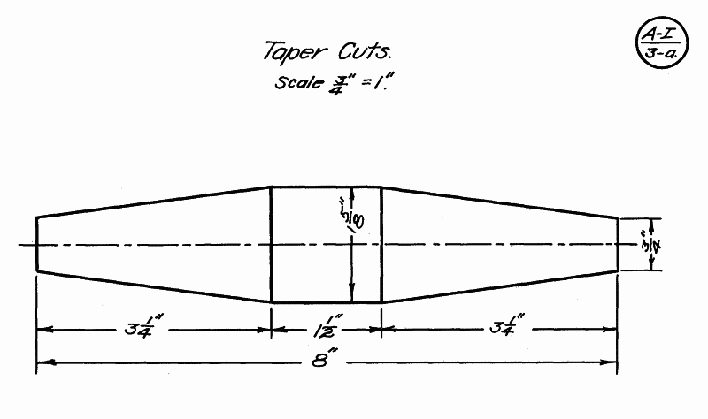
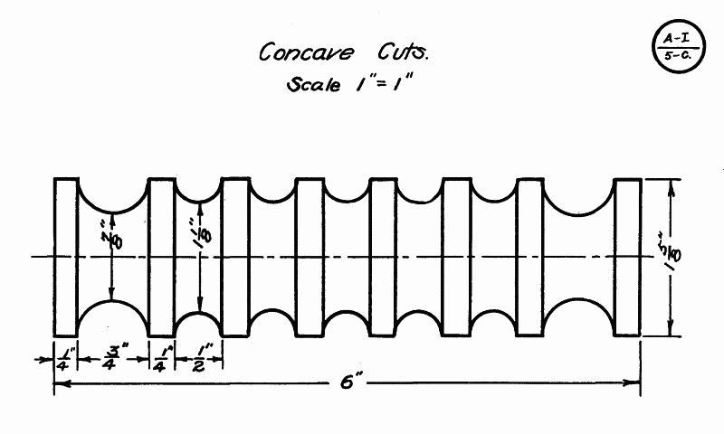
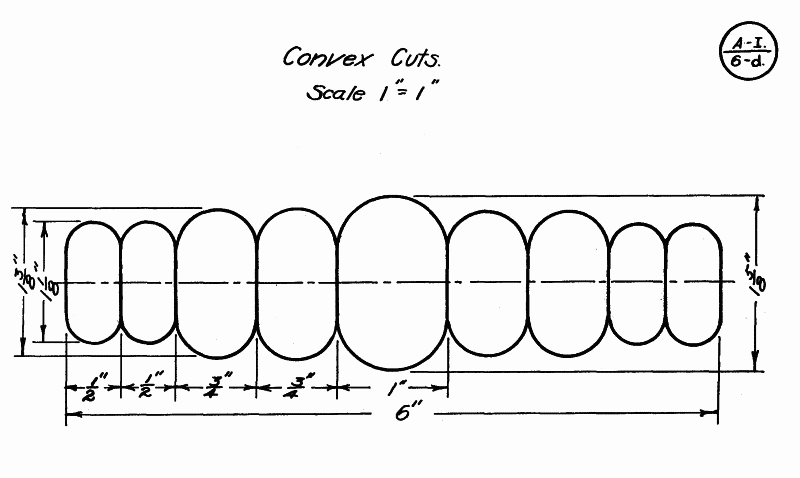
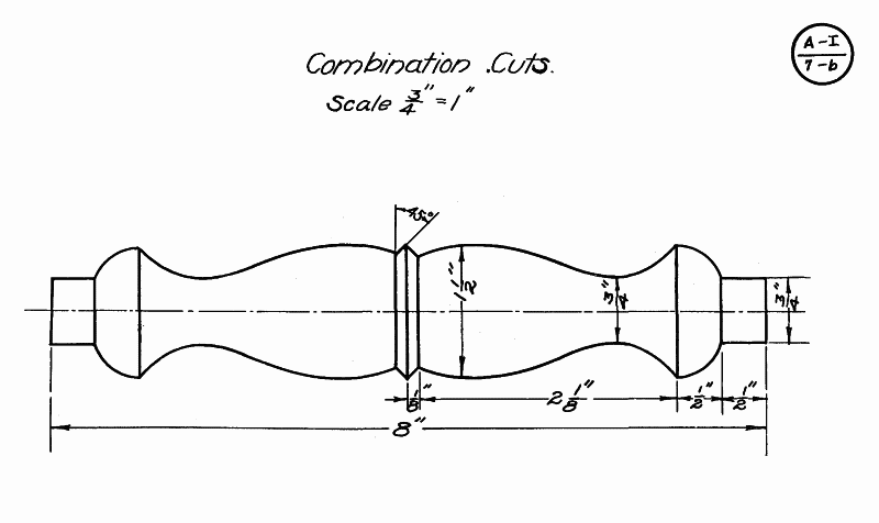
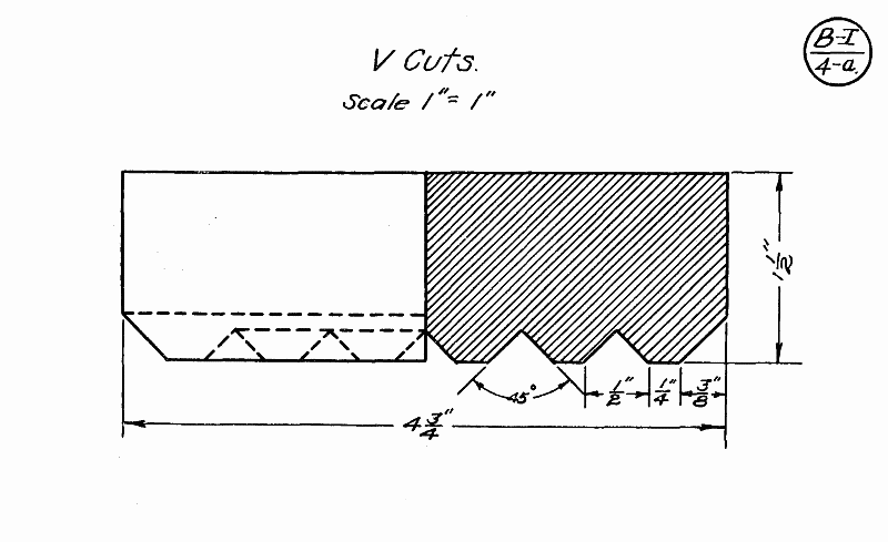
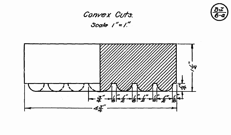
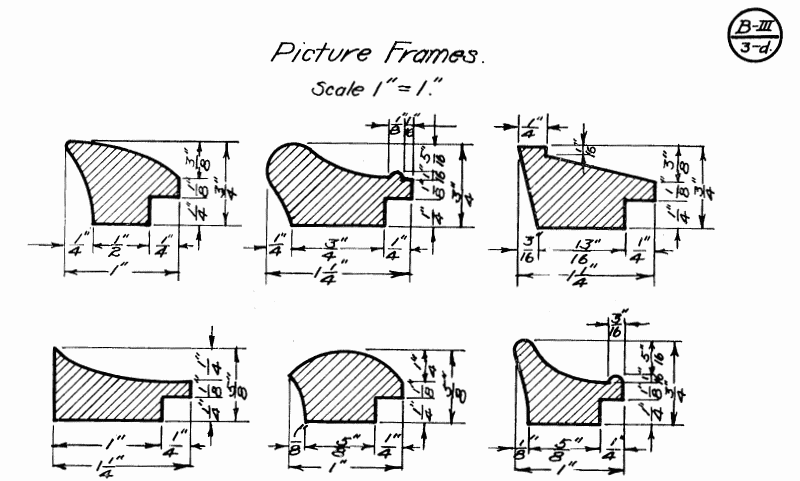
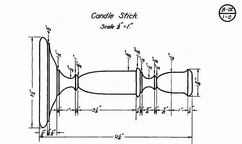
To remove the sphere tap the chuck lightly with a hammer just above it, at the same time pull out on the sphere.
To remove the sphere, gently tap the chuck with a hammer just above it while pulling the sphere out.
CHAPTER XI
SPIRAL TURNING
SPIRAL TURNING
Spiral turning is a subject that has received very little attention by most schools in which wood turning is taught. Spiral work is seen in antique furniture and also in the modern furniture of the present day. It seems that it takes the wheel of fashion about a century to make a complete turn, for what our forefathers neglected and destroyed the people of the present day value and cherish.
Spiral turning is a topic that hasn’t been given much focus in most schools that teach woodturning. You can find spiral work in antique furniture as well as in today’s modern furniture. It appears that it takes about a century for trends to come back around, as what our ancestors overlooked and discarded is now appreciated and valued by people today.
Spiral work gives excellent practice in shaping and modelling wood. It brings into play the principle of the helix as used in cutting threads, etc.; and its form, size and shape may be varied according to the taste of the individual. As in threads so in spiral work we have single and double spirals, and their form and proportion depend upon their use and application in furniture making. A variation of the spiral may be made in several ways: First, by changing the number of turns of the spiral on a straight shaft; second, by running a spiral on a tapered shaft; third, by changing the shape or form of the spiral itself; and fourth, by making more than one spiral on a shaft. It is uncommon to see ten or twelve spirals running around a single shaft.
Spiral work provides great practice in shaping and modeling wood. It uses the helix principle, similar to what’s used in cutting threads, etc.; and its form, size, and shape can be adjusted based on personal taste. Just like with threads, in spiral work, we have single and double spirals, and their design and proportions are determined by their intended use in furniture making. You can create variations of the spiral in several ways: first, by altering the number of turns on a straight shaft; second, by applying a spiral to a tapered shaft; third, by changing the shape or design of the spiral itself; and fourth, by adding more than one spiral to a shaft. It’s rare to see ten or twelve spirals wrapped around a single shaft.
Some of the forms of the above types are fully taken up and explained in the work that is to follow.
Some of the forms mentioned above are fully discussed and explained in the work that follows.
PLATES __A_TAG_PLACEHOLDER_0__, __A_TAG_PLACEHOLDER_1__. SINGLE SPIRAL. STRAIGHT SHAFT
To work out a single spiral for a pedestal proceed as follows:
To create a single spiral for a pedestal, follow these steps:
1. Turn a cylinder 2¼" in diameter. Make the ends slightly larger in order that the design may be turned on each, after the spiral has been worked out.
1. Turn a cylinder 2¼" in diameter. Make the ends a bit larger so that the design can be carved on each end after the spiral has been completed.
2. Lay off spaces 2-1/16" apart on the cylinder while the spindle is turning in the lathe and divide each of these into four equal parts. Each one of these large spaces represents one turn of the spiral. A good proportion is slightly less than the diameter of the cylinder; thus the diameter of the cylinder equals 2¼" and the width of the space 2-1/16".
2. Mark off spaces 2-1/16" apart on the cylinder while the spindle is spinning in the lathe and divide each of these into four equal parts. Each of these larger spaces represents one complete turn of the spiral. A good proportion is just under the diameter of the cylinder; therefore, if the diameter of the cylinder is 2¼", the width of the space is 2-1/16".
3. On the cylinder parallel to the axis draw lines A-A B-B C-C D-D. These lines should be 90° apart as shown in the top diagram (Plate B-V--1-a’). Line D-D is on the other side of the cylinder as shown in the top and middle diagrams.
3. On the cylinder parallel to the axis, draw lines A-A, B-B, C-C, and D-D. These lines should be 90° apart as shown in the top diagram (Plate B-V--1-a’). Line D-D is on the opposite side of the cylinder as illustrated in the top and middle diagrams.

Fig. 23.
Fig. 23.
4. Start on line A-A at point X, circle 1, and draw a line connecting it with line B-B on circle 1’. Then connect B-B on circle 1’ with C-C on circle 2 and so on until a spiral has been drawn the entire length of the cylinder. This line will form the ridge of the spiral as shown in the middle diagram.
4. Begin at point X on line A-A of circle 1, and draw a line connecting it to line B-B on circle 1’. Next, connect B-B on circle 1’ to C-C on circle 2, and keep going until you’ve drawn a spiral the whole length of the cylinder. This line will create the ridge of the spiral, as demonstrated in the middle diagram.
5. Next begin on line C-C at circle 1, and draw a line connecting it with D-D on circle 1’ then to line A-A on circle 2, and so on as before. This spiral represents the center of the groove or the portion which is to be cut away. This is not shown in the diagram because more or less confusion would be caused with the line representing the ridge of the spiral.
5. Next, start at line C-C at circle 1 and draw a line connecting it to D-D on circle 1’, then to line A-A on circle 2, and continue the same way as before. This spiral represents the center of the groove or the part that will be cut away. This isn't shown in the diagram because it would create confusion with the line representing the ridge of the spiral.
6. Begin on line C-C at circle 1, and saw to a depth of ¾". Saw the entire length of the cylinder leaving about 1½" at the ends. Do not follow the line here, but switch off gradually and follow circles 1 and 15, so as to allow the spiral to begin and end gradually and not abruptly.
6. Start at line C-C at circle 1 and cut to a depth of ¾". Saw the whole length of the cylinder, leaving about 1½" at each end. Don’t stick to the line here; instead, gradually shift off and follow circles 1 and 15 to ensure that the spiral starts and ends smoothly, not suddenly.
7. Rough out with a knife or chisel by cutting on both sides of the saw cut. Then use a wood rasp to finish shaping out the spiral. When properly shaped out allow the lathe to turn slowly and smooth with sandpaper by following the spiral as the lathe turns.
7. Rough out with a knife or chisel by cutting on both sides of the saw cut. Then use a wood rasp to finish shaping the spiral. Once it's properly shaped, let the lathe turn slowly and smooth it down with sandpaper, following the spiral as the lathe turns.
 Fig. 24. |
 Fig. 24-a. |
 Fig. 25. |
PLATES B-V--2-a, B-V--2-a’, B-V--2-a’’;. SINGLE SPIRAL. TAPERED SHAFT
PLATES __A_TAG_PLACEHOLDER_0__, __A_TAG_PLACEHOLDER_1__, __A_TAG_PLACEHOLDER_2__; SINGLE SPIRAL. TAPERED SHAFT
To lay off a single spiral for the electric lamp shown in Figs. 24 and 24a proceed as follows:
To create a single spiral for the electric lamp shown in Figs. 24 and 24a, follow these steps:
1. Select your wood and bore a hole through it. Plug the hole and center the piece in the lathe. This insures getting the hole exactly in the center, and it will not be cut into while the cutting of the groove of the spiral proceeds. A groove may also be cut in two pieces of stock and glued together to form a hole through the stock.
1. Choose your wood and drill a hole through it. Plug the hole and position the piece in the lathe. This ensures that the hole is perfectly centered, and it won’t be cut into while you carve the groove of the spiral. You can also cut a groove in two pieces of wood and glue them together to create a hole through the stock.
2. Turn a cylinder 2½" in diameter, tapering it to 1½" at the one end; this part should be 12⅛" long. Both ends should be left larger than 2½" as the lower and upper designs must be cut here.
2. Turn a cylinder 2½" in diameter, tapering it to 1½" at one end; this part should be 12⅛" long. Both ends should be left larger than 2½" since the lower and upper designs need to be cut here.
3. Let the spindle revolve in the lathe and draw circles as shown in the layout (Plate B-V--2-a’). The number of circles will vary with the taper. Since seven turns are needed in the present spiral, 28 circles will be necessary--four circles for each turn of the spiral as shown in the middle diagram. A good proportion to follow is to measure the diameter of the spindle at circle 2 and lay off this distance from circle 1 to circle 3. Then measure the diameter at circle 4 and lay off this diameter from circle 3 to circle 5 and so on until all circles have been made. Then divide these large divisions into four equal parts.
3. Let the spindle spin in the lathe and create circles as shown in the layout (Plate B-V--2-a’). The number of circles will change based on the taper. Since seven turns are needed for the current spiral, 28 circles will be required—four circles for each turn of the spiral as indicated in the middle diagram. A good rule to follow is to measure the diameter of the spindle at circle 2 and mark this distance from circle 1 to circle 3. Then measure the diameter at circle 4 and mark this diameter from circle 3 to circle 5, and continue this process until all circles are created. Finally, divide these larger divisions into four equal parts.
4. Draw four lines the entire length of the spindle, each 90° apart as shown by the heavy lines in the middle diagram. The heavy circles of the same diagram represent the complete turns of the spiral.
4. Draw four lines along the full length of the spindle, each at a 90° angle from the others as shown by the thick lines in the middle diagram. The thick circles in the same diagram represent the full turns of the spiral.
5. Lay out the line representing the ridge of the spiral as shown in the middle diagram. Begin on circle 1, where the straight line crosses it, draw to circle 1’ at the point where the next straight line crosses it, then to 2--2’--3--3’ and so on until the end is reached. This forms the ridge of the spiral as shown in diagram 3. Next it may be more convenient to draw another line representing the groove. In this case begin at point X in the middle diagram, opposite the point where first started, and continue in the preceding manner, making this line parallel to the other line.
5. Draw the line showing the ridge of the spiral as illustrated in the middle diagram. Start at circle 1, where the straight line intersects, and draw to circle 1’ at the point where the next straight line crosses it, then to 2--2’--3--3’ and so on until you reach the end. This creates the ridge of the spiral as shown in diagram 3. Next, it might be easier to draw another line for the groove. In this case, start at point X in the middle diagram, directly across from where you began, and continue in the same way, making this line parallel to the other line.
6. Saw on the line last made, being careful not to saw too deeply. The depth must be ¼" less than half the diameter of the spindle where the cut is made. This saw cut forms the groove of the spiral. The groove is then cut out by hand with a chisel or knife, by working down the wood on both sides of the saw cut. After the spirals have been roughed out, a rasp is used to finish shaping them. The work is then sandpapered smooth, while the spindle is revolved slowly in the lathe.
6. Saw along the last line you made, being careful not to cut too deep. The depth should be ¼" less than half the diameter of the spindle where you’re cutting. This saw cut creates the groove for the spiral. The groove is then carved out by hand with a chisel or knife, working down the wood on both sides of the saw cut. Once the spirals are roughly shaped, a rasp is used to refine their shape. The work is then sanded smooth while the spindle slowly rotates in the lathe.
7. Cut designs on the ends of the cylinder and polish.
7. Cut designs on the ends of the cylinder and polish them.
PLATES __A_TAG_PLACEHOLDER_0__, __A_TAG_PLACEHOLDER_1__. DOUBLE SPIRAL. TAPERED SHAFT
To work out a double spiral for the electric lamp illustrated in Fig. 25 proceed as follows:
To create a double spiral for the electric lamp shown in Fig. 25, follow these steps:
1. Turn up the spindle in the usual manner. Since the base of the shaft is larger than the top, the spiral must also be in proportion and lines A-A’, B-B’, C-C’, D-D’, and E-E’, are drawn around the shaft. To get the approximate spacing from circles A-A to B-B measure the diameter at A-A’ plus about 3/16" and lay off from A-A’ to B-B’. Then take the diameter of B-B’ plus about 3/16" and lay off from A-A’ to B-B’. Then take the diameter at B-B’ plus about 3/16" and lay off from circle B-B’ to C-C’ and so on. If the shaft is tapered more, a different proportion must be used. Also if it is desired to have the twist wind around the shaft three times, a variation must be made in the number of circles.
1. Raise the spindle as usual. Since the base of the shaft is wider than the top, the spiral needs to match that proportion, and lines A-A’, B-B’, C-C’, D-D’, and E-E’ are drawn around the shaft. To get the approximate spacing from circles A-A to B-B, measure the diameter at A-A’ and add about 3/16", then mark that distance from A-A’ to B-B’. Next, take the diameter of B-B’ plus about 3/16" and mark from A-A’ to B-B’. Then take the diameter at B-B’ plus about 3/16" and mark from circle B-B’ to C-C’, and so on. If the shaft is tapered more, a different proportion should be used. Also, if you want the twist to wrap around the shaft three times, you need to adjust the number of circles accordingly.

Fig. 27.
Fig. 27.
2. If it is desired to have the twist wind around the shaft twice, draw circles 1-1’, 2-2’, 3-3’, and 4-4’ and the spaces will grow proportionately smaller at the small end.
2. If you want the twist to wrap around the shaft twice, draw circles 1-1’, 2-2’, 3-3’, and 4-4’, and the spaces will get proportionately smaller at the small end.
3. Draw four lines running lengthwise on the spindle and 90° apart as shown in the midde figure in heavy lines (Plate B-V--2-b’).
3. Draw four lines running lengthwise on the spindle, spaced 90° apart, as shown in the middle figure in bold lines (Plate B-V--2-b’).
4. Begin at A and draw a curved line to where the 90° line crosses circle 1-1’. From there extend the line to where the next 90° line crosses circle B-B’ at point B’. Continue in this manner until the other end of the shaft is reached. Begin at A’ and draw a line on the opposite side of the shaft. These two lines running around and along the shaft form the grooves while the portion in between forms the beads of the double spiral.
4. Start at A and draw a curved line to the point where the 90° line intersects circle 1-1’. From there, extend the line to where the next 90° line crosses circle B-B’ at point B’. Keep going in this way until you reach the other end of the shaft. Start at A’ and draw a line on the opposite side of the shaft. These two lines wrapping around the shaft create the grooves, while the section in between forms the beads of the double spiral.
5. Saw to the desired depth, being ¼" less than half the diameter at the point where cut. With a chisel or knife form the grooves and beads. It is necessary to be careful about not ending the grooves too abruptly. (See point 6 in Plates B-V--1-a, B-V--1-a’.) Smooth with a rasp and sandpaper while the lathe is revolving slowly.
5. Cut to the desired depth, which should be ¼" less than half the diameter at the cutting point. Use a chisel or knife to shape the grooves and beads. Be careful not to make the ends of the grooves too sharp. (See point 6 in Plates B-V--1-a, B-V--1-a’.) Smooth it out with a rasp and sandpaper while the lathe is turning slowly.
6. Cut the design on the ends and polish.
6. Trim the design at the ends and smooth it out.
To work out the double groove spiral for the magazine holder illustrated, proceed as follows:
To create the double groove spiral for the magazine holder shown, follow these steps:
1. Square up the stock to 1⅜". Center carefully and turn the design on both ends as shown, in the upper diagram (Plate B-V--3-a’). Turn the cylinder between the top and bottom, making it 5½" long and 1⅜" in diameter.
1. Square the stock to 1⅜". Carefully center it and shape the design on both ends as shown in the upper diagram (Plate B-V--3-a’). Rotate the cylinder between the top and bottom to make it 5½" long and 1⅜" in diameter.

Fig. 26.
Fig. 26.
2. Divide the cylinder into two equal parts. Each part represents one revolution of the spiral.
2. Split the cylinder into two equal halves. Each half represents one full revolution of the spiral.
3. Divide each half into four equal parts as shown in the top and center diagrams (Plate B-V--3-a’), 1-1’, 2-2’, 3-3’ and so on. The proportion of the distance between these circles should be one-half the diameter of the cylinder.
3. Split each half into four equal sections as illustrated in the top and center diagrams (Plate B-V--3-a’), 1-1’, 2-2’, 3-3’, and so forth. The spacing between these circles should be half the diameter of the cylinder.
4. Draw lines A-A, B-B, C-C, and D-D, parallel to the axis of the cylinder 90° apart.
4. Draw lines A-A, B-B, C-C, and D-D, parallel to the axis of the cylinder and spaced 90° apart.
5. With a band 3/16" wide of any substantial material (preferably a narrow strip of tin or a watch main spring) begin on the line A-A at circle 1, and connect circle 1’ at line B-B, and then connect circle 2 at C-C, and so on until the spiral is made the entire length. Mark on both sides of the 3/16" band so as to keep the spiral parallel.
5. Using a band that's 3/16" wide made of any durable material (ideally a narrow strip of tin or a watch spring), start at line A-A at circle 1, then connect to circle 1' at line B-B, followed by connecting to circle 2 at line C-C, and continue this process until the spiral is completed to its full length. Make sure to mark both sides of the 3/16" band to keep the spiral parallel.
6. Next begin at the line C-C where circle 1 crosses it and connect from here to 1’ at B-B. Proceed as in Step 5, as shown in the center diagram.
6. Next, start at the line C-C where circle 1 intersects it and connect from there to 1’ at B-B. Proceed as in Step 5, as shown in the center diagram.
7. Now erase the extreme ends of the spiral near circles 1 and 5, and deviate from the original spiral and follow the circles in a more parallel direction so as to allow the spiral to begin and end gradually and not too abruptly. Refer to the lower diagram for this.
7. Now remove the extreme edges of the spiral near circles 1 and 5, and shift away from the original spiral to follow the circles in a more parallel direction. This will help the spiral start and end more gradually instead of abruptly. Check the lower diagram for this.
8. Cut out portions of wood between the bands previously marked around, as shown in the lower figure. The wood should be cut out with a knife so as to leave the corners sharp on the narrow bands. The portion cut out should be a semi-circle and can be sanded by making a spindle a little smaller than the distance between the bands and fastening sandpaper on the spindle. Place in the lathe and hold the spiral on the sandpaper cylinder at an angle so that the spiral will fit. Turn gradually and the sandpaper will smooth up the portion between the bands and true it up. At the ends where the grooves are smaller, use a smaller stick around which sandpaper has been wound and work out by hand.
8. Cut out the pieces of wood between the bands that you marked earlier, as shown in the lower figure. Use a knife to make the cuts so that the corners remain sharp on the narrow bands. The cutout should be a semi-circle and can be smoothed using a spindle that's slightly smaller than the gap between the bands with sandpaper attached to it. Place it in the lathe and hold the spiral against the sandpaper cylinder at an angle to ensure a good fit. Turn it gradually, and the sandpaper will smooth out the area between the bands. For the ends where the grooves are narrower, use a smaller stick wrapped in sandpaper and finish it off by hand.
9. It is well to cut straight down, about 1/32" deep, along the lines marking out the narrow bands. Then the wood will not be so likely to split while removing the stock which forms the grooves between the bands.
9. It's best to cut straight down, about 1/32" deep, along the lines outlining the narrow bands. This way, the wood is less likely to split while you're removing the material that creates the grooves between the bands.
10. Cut out the mortises in the square portions which have been left at both ends. Make the frame work for the sides and cane. Glue together and polish.
10. Cut out the mortises in the square parts that have been left at both ends. Build the frame for the sides and cane. Glue everything together and polish.
Note:--By making the posts smaller and using the same construction for a side a nice looking book stall may be made. The proportions for the posts are the same as mentioned in Step 3.
Note:--By making the posts smaller and using the same design for a side, you can create an attractive book stall. The dimensions for the posts are the same as mentioned in Step 3.
[Transcribers note: There are 142 line art illustrations after this point in the book. See the Classification of Plates for all of them.]
[Transcribers note: There are 142 line art illustrations after this point in the book. See the Classification of Plates for all of them.]
Download ePUB
If you like this ebook, consider a donation!