This is a modern-English version of Scientific American Supplement, No. 623, December 10, 1887, originally written by Various.
It has been thoroughly updated, including changes to sentence structure, words, spelling,
and grammar—to ensure clarity for contemporary readers, while preserving the original spirit and nuance. If
you click on a paragraph, you will see the original text that we modified, and you can toggle between the two versions.
Scroll to the bottom of this page and you will find a free ePUB download link for this book.

SCIENTIFIC AMERICAN SUPPLEMENT NO. 623
NEW YORK, DECEMBER 10, 1887
Scientific American Supplement. Vol. XXIV., No. 623.
Scientific American established 1845
Scientific American Supplement, $5 a year.
Scientific American and Supplement, $7 a year.
TABLE OF CONTENTS.
BENIER'S HOT AIR ENGINE.
The hot air engine, although theoretically recognized for some time past as the most economical means of converting heat into motive power, has up to the present met with little success. This is due to the fact that the arrangement of the motors of this class that have hitherto been constructed has been such as to render them but slightly practical. In the Benier hot air engine (illustrated herewith), however, obstacles that were once considered insurmountable have been overcome, and the motor presents many advantages over all the types that have preceded it. Among such advantages we shall cite the possibility of utilizing air at a high temperature (1,200 or 1,500 degrees), while the rubbing surfaces remain at a moderate temperature (60 or 80 degrees). The fire grate is placed in the interior of the cylinder, and is traversed by the cold air forced by a pump. The expanded hot gases fill the cylinder and act against the piston directly above the grate.
The hot air engine, although recognized for some time as the most efficient way to convert heat into power, has so far not had much success. This is mainly because the designs of these engines that have been built until now have made them only somewhat practical. However, the Benier hot air engine (illustrated here) has overcome obstacles that were once thought impossible, offering many advantages over previous models. Some of these advantages include the ability to use air at high temperatures (1,200 to 1,500 degrees), while keeping the rubbing surfaces at a moderate temperature (60 to 80 degrees). The fire grate is located inside the cylinder and is crossed by cold air pushed in by a pump. The expanded hot gases fill the cylinder and push directly against the piston above the grate.
The type herewith illustrated is of 6 horse power. The motive cylinder, CC', is bolted to the extremity of the frame, A. Upon this latter is fixed a column, B, which carries a working beam, E. This latter transmits the motion of the piston, P, to the shaft, D. A pump, G, placed within the frame, forces a certain quantity of cold air at every revolution into the driving cylinder. The piston of this pump is actuated by the connecting rod, G', jointed to the lever, F', which receives its motion from the rod, F. A slide valve, b', actuated by a cam, regulates the entrance of the cold air into the pump during suction, as well as its introduction into the cylinder. There is a thrust upon the piston during its upward travel, and an escape of hot gas through the eduction valve, h, during the downward travel.
The type shown here has a power of 6 horsepower. The motive cylinder, CC', is attached to the end of the frame, A. A column, B, is fixed on this frame, which supports a working beam, E. This beam transmits the motion of the piston, P, to the shaft, D. A pump, G, located within the frame, forces a specific amount of cold air into the driving cylinder with every revolution. The piston of this pump is moved by the connecting rod, G', which is connected to the lever, F', that gets its motion from the rod, F. A slide valve, b', operated by a cam, controls the entrance of cold air into the pump during suction and its delivery into the cylinder. The piston experiences a thrust during its upward movement and hot gas escapes through the exhaust valve, h, during the downward movement.
The cylinder is in two parts, C and C'. The piston, which is very long, rubs at its upper end against the sides of the cylinder, C. The lower end is of smaller diameter, and leaves an annular space between it and the cylinder. The grate is at the bottom of the cylinder, C'. The sides of the cylinder at the level of the fire box are protected with a lining of plumbago. When the piston is at the bottom of its travel, the eduction valve closes. The slide valve, b', establishes a communication between the pump chamber and the cylinder. The air contained in the pump is already compressed in the latter to a pressure of nearly a kilogramme at the moment of the communication. This air enters the cylinder, and the communication between the latter and the pump continues until all the air is forced into the driving cylinder, the piston of the pump being at the bottom of its travel, and that of the cylinder about midway.
The cylinder has two parts, C and C'. The piston, which is quite long, rubs against the sides of the cylinder, C, at its upper end. The lower end has a smaller diameter, creating an annular space between it and the cylinder. The grate is located at the bottom of the cylinder, C'. The sides of the cylinder at the level of the firebox are lined with plumbago for protection. When the piston reaches the bottom of its travel, the eduction valve closes. The slide valve, b', creates a connection between the pump chamber and the cylinder. The air in the pump is already compressed to nearly a kilogramme of pressure at the moment the connection is made. This air flows into the cylinder, and the connection between the cylinder and the pump continues until all the air is pushed into the driving cylinder, with the piston of the pump at the bottom of its travel and the piston of the cylinder about halfway up.

BENIER'S HOT AIR ENGINE.
BENIER'S HOT AIR ENGINE.
The air forced by the pump piston enters the cylinder through two conduits, one of which leads a portion of it toward the top of the cylinder, and the other toward the bottom. The lower conduit debouches under the grate, and the air that passes through it traverses the fire box, and the hot gas fills the cylinder. The conduit that runs to the top debouches in the cylinder, C, at the lower limit of the surface rubbed by the piston. The air that traverses this conduit is distributed through the annular space between the piston and cylinder. The hot gas derived from combustion can therefore never introduce itself into this annular space, and consequently cannot come into contact with the rubbing surfaces of the cylinder and piston.
The air pumped by the piston enters the cylinder through two pipes. One takes a portion of it to the top of the cylinder, while the other takes it to the bottom. The lower pipe opens under the grate, and the air that goes through it moves through the firebox, filling the cylinder with hot gas. The pipe that goes to the top opens in the cylinder, C, at the lower end of the area touched by the piston. The air that flows through this pipe is spread out in the space between the piston and cylinder. This way, the hot gas from combustion can never enter this space and therefore cannot touch the surfaces where the cylinder and piston rub together.
As the quantity of air introduced at every stroke is constant, the work developed at every stroke is varied by regulating the temperature of the gas that fills the cylinder. When the temperature falls, the pressure, and consequently the work developed, diminishes. This result is obtained by varying the respective quantities of air that pass through the fire box and around the piston. In measure as less air passes through the fire box, the quantity that passes around the piston augments by just so much, and the pressure diminishes. A valve, n', in the conduit that runs to the fire box is controlled by the regulator, L', in the interior of the column. When the work to be transmitted diminishes, the regulator closes the valve more or less, and the work developed diminishes.
As the amount of air pumped in each stroke is consistent, the work produced in each stroke changes by adjusting the temperature of the gas inside the cylinder. When the temperature drops, the pressure, and therefore the work produced, decreases. This result is achieved by altering the respective amounts of air that flow through the fire box and around the piston. As less air moves through the fire box, the amount that moves around the piston increases by the same amount, and the pressure decreases. A valve, n', in the pipe leading to the fire box is managed by the regulator, L', inside the column. When the work that needs to be transmitted decreases, the regulator closes the valve to varying degrees, leading to a reduction in the work produced.
The coke is put by shovelfuls into a hopper, I. Four buckets mounted upon the periphery of a wheel, I', traverse the coke, and, taking up a piece of it, let it fall upon the cover, J, of the slide valve, j, whence it falls into the cavity of the latter when it is uncovered, and from thence into the conduit, c', of the box, j', when the cavity of the valve is opposite the conduit. From the conduit, c', the coke falls upon the grate.
The coke is loaded by shovelfuls into a hopper, I. Four buckets attached to the edge of a wheel, I', move over the coke, scoop up a piece, and drop it onto the cover, J, of the slide valve, j. When the valve is uncovered, it falls into the cavity of the valve and then into the conduit, c', of the box, j', when the valve cavity is aligned with the conduit. From the conduit, c', the coke drops onto the grate.
A small sight hole covered with glass, in the cover, J, permits the grate to be seen when the cavity of the valve is opposite c'.
A small sight hole covered with glass in the cover, J, allows the grate to be seen when the valve's cavity is opposite c'.
As in gas engines, a current of water is made to flow around the cylinder, C', in order to keep the sides from getting too hot.
As in gas engines, water is circulated around the cylinder, C', to prevent the sides from overheating.
In order to set the engine in motion, we begin by opening the bottom, C, of the cylinder, C', to clean the grate. This done, we close C and introduce lighted charcoal through the conduit, c' (the valve being open). The valve is put in place, two or three revolutions are given to the fly wheel, and the motor starts. The feeding is afterward done with coke.
To get the engine started, we first open the bottom, C, of the cylinder, C', to clean the grate. Once that's done, we close C and add lit charcoal through the conduit, c' (with the valve open). We put the valve in place, give the flywheel a couple of turns, and the motor begins to run. After that, we use coke for fueling.
The parts that transmit motion operate under conditions analogous to those under which the same parts of a steam engine do. The air pump sucks and forces nothing but cold air, and nothing but cold air passes through the distributing slide valve. The pump and valve are therefore rendered very durable. The piston and cylinder, at the points where friction exists, are at a temperature of 60 or 80 degrees. These surfaces are protected against hot gas charged with dust.
The components that move things work under conditions similar to those in a steam engine. The air pump only draws in and pushes out cold air, and only cold air flows through the distributing slide valve. This makes the pump and valve very durable. The piston and cylinder, where there is friction, operate at temperatures of 60 to 80 degrees. These surfaces are shielded from hot gas that contains dust.
The hot gas, which escapes from the cylinder through a valve, has previously been cooled by contact with the sides of the cylinder and by expansion. The eduction valve just mentioned works about like that of a steam engine, and it is only necessary to polish it now and then in order to keep it in good condition.—Annales Industrielles.
The hot gas that escapes from the cylinder through a valve has already been cooled by touching the sides of the cylinder and by expanding. The mentioned eduction valve works similarly to that of a steam engine, and it only needs to be polished occasionally to stay in good shape.—Annales Industrielles.
YOUR FUTURE PROBLEMS.1
By CHARLES E. EMERY.
Mr. President and Ladies and Gentlemen: It has not been considered the duty of the speaker, in addressing the graduating class, to dwell on the triumphs of science or the advantage of a liberal education. These subjects have already been discussed, in connection with the regular courses of study, better, and more at length, than he could do. We propose rather to try and prepare the minds of the graduates for the practical problems before them.
Mr. President and Ladies and Gentlemen: It hasn’t been the speaker’s role, in addressing the graduating class, to focus on the achievements of science or the benefits of a liberal education. Those topics have already been covered in connection with the regular courses of study, in more depth and better than he could manage. Instead, we aim to help the graduates get ready for the practical challenges ahead of them.
All young men are impressed with the consciousness of higher powers as they increase their stores of knowledge, and this feeling perhaps reaches its maximum with those who have made a specialty of the investigation and application of physical laws. Young men who have learned how to harness the powers of nature and guide them to do their will are apt to belittle the difficulties they have yet to overcome, and have a false impression of the problems of life. This feeling is shown to a minimum extent by graduates of the Stevens Institute, on account of their careful practical training, in connection with the thorough study of principles; but it has been thought best for one from the outside world to supplement such teaching by calling to mind instances which may have a useful counteracting effect, and, like parables, serve the purpose of illustrative instruction.
All young men are captivated by the idea of greater powers as they expand their knowledge, and this feeling often peaks for those who focus on studying and applying physical laws. Young men who have learned to use natural forces and direct them to achieve their goals tend to downplay the challenges they still face and have a distorted view of life's problems. Graduates from the Stevens Institute show this feeling to a lesser degree because of their thorough practical training alongside a solid understanding of principles; however, it seems beneficial for someone from the outside to enhance this education by highlighting examples that may provide a useful counterbalancing effect, which, like parables, can serve as illustrative lessons.
Gentlemen of the Class of '87: It was the pleasure of the speaker to address the class of '79, under the title of "How to Succeed," some words of counsel and warning, which, if they left an impression of severity at the time, were apparently so well received afterward that he has been tempted to continue the general subject, with the title of "Your Future Problems." The notation of your future problems will not be found at once among the known quantities, but with x, y, and z, at the other end of the alphabet. Often word symbols will be applicable, expressing at times disappointment and pain, at other times renewed effort, and finally the active phases of individual thought and exertion.
Gentlemen of the Class of '87: It was the speaker's pleasure to address the class of '79 with a talk titled "How to Succeed," offering some advice and caution. While it may have come off as harsh at the time, it seems to have been well received afterward, which has encouraged him to extend the topic with a new title: "Your Future Problems." The notation of your future problems won't be found right away among the known quantities, but rather with x, y, and z at the other end of the alphabet. Often, word symbols will apply and can convey feelings of disappointment and pain at times, and at other times, a renewed effort, and finally, the active phases of individual thought and action.
The first serious problem with many of you will be to secure satisfactory engagements. This problem cannot be illustrated by parables. It needs, in general, patient, unremitting, and frequently long continued effort. It may be that the fame of some of you, that have already acquired the happy faculty of making yourselves immediately useful, has already gone abroad and the coveted positions been already assured. To be frank, we cannot promise you even a bed of roses. We have in mind an instance where a superior authority in a large business enterprise who had great respect, as he should have, for the attainments of young gentlemen who have had the opportunities of a technical education, deliberately ordered out a competent mechanical engineer, familiar with the designs required in a large repair shop, and sent in his place a young gentleman fresh from school and flushed with hope, but who from the very nature of the case could know little or nothing of his duties at that particular place. He was practically alone in the drawing room, and did not know where to find such drawings as were required, and candor requires it to be said that he desired to ask many questions about those he did find. The superintendent unfortunately had nothing to do with his appointment, and rather resented it. So he did not trust any of his work, and the new comer was obliged to learn his practical experience at that establishment, where he was known as the mechanical engineer, by having all his work done over by the pattern maker or others, under the eye of the superintendent or master mechanic, and be subjected all the time to the jealousies and annoyances incident to such a method of introduction.
The first significant challenge for many of you will be finding satisfying job placements. This issue can't be solved with simple examples. It generally requires patient, persistent, and often lengthy effort. Some of you may have already gained a good reputation for being immediately valuable, and you might have secured those sought-after positions. To be honest, we can't promise you an easy path. We have in mind a situation where a respected leader in a large business, who properly valued the skills of young men with a technical education, intentionally assigned a capable mechanical engineer, experienced in the designs needed for a big repair shop, and instead sent in a recent graduate, full of hope but lacking the necessary knowledge for that specific role. He found himself mostly alone in the drawing room and didn’t know where to locate the drawings he needed. It’s important to note he wanted to ask many questions about the ones he did find. Unfortunately, the superintendent had no say in his appointment and was quite frustrated about it. As a result, he didn’t trust any of the newcomer’s work, forcing him to learn through practical experience at the company, where he was known as the mechanical engineer. He ended up having all his work redone by the pattern maker or others, constantly under the supervision of the superintendent or master mechanic, and dealing with the jealousy and frustrations that came with such an awkward introduction.
His practical experience was certainly learned under difficulties which I trust none of you may experience. This statement is made that those of you who have not yet obtained positions may not envy those who have, and that each and all of you may be careful not to take a position so far above your experience, if not your capacity, as to become unpleasantly situated in the beginning. The educational facilities you have enjoyed are of such great value in some exceptional cases that the parties thus benefited may do you an injury by leading others to expect that you will be equally valuable in performing duties which require much more practical experience and knowledge of detail than it is possible that you could have obtained in the time you have been here.
His practical experience was definitely gained through challenges that I hope none of you will face. I'm saying this so that those of you who haven't landed jobs won't envy those who have, and I want to remind all of you to be cautious about accepting a role that's too far beyond your experience, or even your skills, as it may lead to difficult situations right at the start. The educational opportunities you've had are so valuable in some rare cases that those who have benefited from them might unintentionally harm you by making others expect you to be just as capable in handling responsibilities that need much more practical experience and in-depth knowledge than you could have possibly gained during your time here.
The incident is ripe with suggestions. No matter how humble a position you may take in the beginning, you will be embarrassed in much the same way as the young gentleman in question, though it is hoped in a less degree. Your course of action should be first to learn to do as you are told, no matter what you think of it. And above everything keep your eyes and ears open to obtain practical knowledge of all that is going on about you. Let nothing escape you of an engineering nature, though it has connection with the business in hand. It may be your business the next day, and if you have taken advantage of the various opportunities to know all about that particular matter in every detail, you can intelligently act in relation to it, without embarrassment to yourself and with satisfaction to your superior.
The situation is full of insights. No matter how low-key your role may be at first, you’ll feel just as awkward as the young man in question, though hopefully to a lesser extent. Your first step should be to learn to follow directions, regardless of your opinion about them. Above all, stay observant to gain practical knowledge of everything happening around you. Don’t overlook anything related to engineering, even if it seems unrelated to your current task. It might become your responsibility the next day, and if you've seized the chance to understand that specific issue in detail, you can respond to it intelligently, without feeling awkward and with your superior's approval.
Above all, avoid conflict with the practical force of the establishment into which you are introduced. It is better, as we have at another time advised, to establish friendly relations with the workmen and practical men with whom you have to do.
Above all, steer clear of conflict with the established authority you're joining. It's better, as we've advised before, to build friendly relationships with the workers and practical people you’ll be working with.
You are to be spared this evening any direct references to the "conceit of learning," but you are asked and advised to bear with the conceit of ignorance. You will find that practical men will be jealous of you on account of your opportunities, and at the same time jealous of their own practical information and experience, and that they may take some pains to hinder rather than aid you in your attempts to actively learn the practical details of the business. The most disagreeable man about the establishment to persons like you, who perhaps goes out of his way to insult you, and yet should be respected for his age, may be one who can be of greatest use to you. Cultivate his acquaintance. A kind word will generally be the best response to an offensive remark, though gentlemanly words of resentment may be necessary when others are present. Sometimes it will be sufficient to say, "I wish a little talk with you by yourself," which will put the bystanders at a distance and enable you to mature your plans. Ascertain as soon as possible that man's tastes; what he reads and what he delights in. Approach him as if you had no resentment and talk on his favorite topic. If rebuffed, tell a pleasant story, and persist from time to time in the attempt to please, until his hardened nature relaxes and he begins to feel and perhaps speaks to others favorably of you. St. Paul has said: "For though I be free from all men, yet have I made myself servant of all that I might gain the more." This is the keynote of policy, and though in humbling yourself you control and hide your true feelings, recollect that all your faculties are given you for proper use.
You'll be spared any direct mentions of the "conceit of learning" tonight, but you're encouraged to tolerate the conceit of ignorance. You'll notice that practical people may feel envious of your opportunities, while also feeling protective of their own knowledge and experience. They might go out of their way to block rather than help you as you try to learn the practical details of the business. The most unpleasant person in the place to someone like you, who might even insult you, could be the one who has the most to offer. Try to build a relationship with him. A kind word usually works best in response to an offensive comment, although you might need to express some polite resentment when others are around. Sometimes, simply saying, "I'd like to talk with you privately," will push the bystanders away and give you space to develop your plans. Figure out that person's interests as soon as you can—what he reads and what he enjoys. Approach him as if you have no hard feelings and discuss his favorite topic. If he dismisses you, share a lighthearted story, and keep trying to engage him until he starts to soften and maybe even speaks well about you to others. St. Paul said, "For though I be free from all men, yet have I made myself servant of all that I might gain the more." This is the essence of strategy, and while humbling yourself might mean concealing your true feelings, remember that all your abilities are meant for good use.
We have referred to some who have acquired the happy faculty of making themselves immediately useful. This is a much more difficult matter than the words imply. If one of you should be so fortunate as to be ordered to make certain tests almost like those you have already conducted here, or to tabulate the results of tests as you have done it here, or to make inspections akin to those which have been fully explained here, there is every probability the work would be done satisfactorily in the first instance. But let a much simpler case arise, for instance, if a superior hand one of you a letter with the simple instructions, "Get me the facts on that," you may be very much puzzled to know what is to be done and how to do it. It may be that the letter is a request for information in regard to certain work that was carried on in the past, in which case it will be necessary for you to hunt through old records, copy books, engineering notes, drawings, and the like, and get a list of all referring to the subject; to make an abstract of the letters and notes if they are at all complicated; and finally to lay the whole before the overworked superior in a business manner, that he largely from recollection, aided by the references and notes, can write an intelligent answer in a very brief period. The way not to do it would be to say, "Yes, sir," very promptly, go off and not more than half read the letter, do something and be back in five minutes with some question or ill-digested answer; then upon receiving a polite hint as to the method to be employed, go off and repeat the operation the next five minutes; then on receiving a short reply, in what appeared to be an unnecessary tone of voice, get a little flurried perhaps, do worse next time, and in the end feel very unpleasant without having accomplished much, and make the gentleman seeking assistance lament the difficulty in teaching young men practical work.
We’ve talked about some people who have the great skill of making themselves useful right away. This is a lot harder than it sounds. If one of you is lucky enough to be told to do some tests similar to those you've already done here, or to compile results like you've done here, or to conduct inspections like those explained here, it’s likely the task would be completed successfully at the outset. But let a much simpler situation come up, like if a supervisor hands one of you a note with the straightforward instruction, “Find out the facts on that,” you might be really confused about what needs to be done and how to tackle it. It could be that the note is asking for information about certain work done in the past, in which case you’ll need to search through old records, notebooks, engineering notes, drawings, and so on, and compile a list of everything relevant to the topic. You would also need to summarize any complicated letters and notes, and ultimately present everything to the busy supervisor in a professional way, so that he can quickly write an informed response based on his memory, along with your references and notes. The wrong approach would be to say, “Yes, sir,” too quickly, then leave and only half-read the letter, do something arbitrary and come back in five minutes with questions or a poorly thought-out answer; then, upon receiving a polite suggestion about how to proceed, leave again and repeat the same mistake after five minutes; then, after getting a short reply that seemed unnecessarily blunt, become a bit flustered, mess up even more next time, and in the end feel quite frustrated without actually accomplishing much, leaving the person seeking help wishing it was easier to teach young people how to do practical work.
It is possible, on the contrary, for a young man to exceed his instructions and volunteer advice that has not been asked. If he has unfortunately gone too far for some time and been sharply spoken to, he may fail the next in not fully doing the work intended. Simply putting down a column of figures would not necessarily mean tabulating facts. The arrangement and rearrangement of the columns aid in classifying such facts, so that the results shown by them will be readily seen and a great deal of labor saved in examination. A good rule in a case of this kind is to try and find some work done by other parties of a similar nature, and thereby ascertain what is needed and expected. Reasonable questions to ascertain, where records are to be found and the kind of records accessible, are always proper if made at the proper time without interrupting an immediate train of thought; and with such information as a start, if a young man will endeavor to imagine himself in a place like that of the one who has finally to decide, and try to ascertain just what information will probably be required, then patiently go to work to find and present it in condensed shape, he from that moment really begins to be useful and his services will be rapidly appreciated. It is a good rule always to keep the memoranda obtained in accomplishing a result of this kind; so that if further information is required, the whole investigation need not be made over.
It’s possible for a young man to go beyond his instructions and offer advice that wasn’t asked for. If he has unfortunately overstepped for a while and been corrected, he might not fully complete the next task. Simply writing down a list of numbers doesn’t automatically mean organizing the facts. Organizing and re-organizing the columns helps classify the facts so that the results are clear and saves a lot of effort during review. A good approach in this situation is to look for similar work done by others to find out what’s needed and expected. Asking reasonable questions about where records are located and what kind of records are available is always appropriate if done at the right time without disrupting the flow of thought. With that information as a starting point, if a young man tries to put himself in the shoes of the person who has to make the final decision and figures out what information is likely needed, then patiently works to find and present it concisely, he will truly start to be useful, and his contributions will be quickly recognized. It’s also wise to keep a record of the notes taken while achieving this kind of result so that if more information is needed, all the work doesn’t have to be repeated.
This remark suggests another line of thought. Some young men with quick perceptions get in the way at school of trusting their memories, and omit making complete notes of lectures or of the various tests illustrating their studies. This carelessness follows them into after life, and there are instances where young men, who can make certain kinds of investigations much better than their fellows, and promptly give a statement of the general nature of the results, have, when called on afterward for the details, forgotten then entirely, and their notes and memoranda, if preserved, being of little use, the labor is entirely lost. Such men necessarily have to learn more careful ways in after life. It is a good rule in this, as in the previous case, to make and copy complete records of everything in such shape that they may be convenient for reference and criticism afterward.
This comment brings up another idea. Some young men with quick minds hinder themselves in school by not trusting their memories and skipping out on taking complete notes during lectures or the various tests that support their studies. This carelessness carries into their later lives, and there are cases where young men, who can conduct certain kinds of research much better than their peers and quickly summarize the general results, completely forget the details when asked later. Their notes and records, if they are kept, often end up being of little use, and all their effort is wasted. These individuals inevitably need to adopt more careful habits in their later lives. Just like in the previous case, a good practice is to create and maintain thorough records of everything in a way that makes them easy to refer back to and critique later.
One of the important problems with which you will have to deal in the future is the labor question, and it is probable that your very first experience with it may be in direct antagonism with the opinions of many with whom you have heretofore been associated. It is an honor to the feelings of those who stand outside and witness this so-called struggle now in progress between capital and labor, that they believe the whole question can be settled by kindly treatment and reasonable argument. There are some cases that will yield to such treatment, and one's whole duty is not performed till all possible, reasonable, and humanitarian methods are adopted. There has been an excuse for the organization of labor, and it, to some small extent, still exists.
One of the important issues you'll have to face in the future is the labor question, and it’s likely that your first experience with it will directly clash with the views of many people you've been associated with before. It's commendable for those who are outside and watching this so-called struggle between capital and labor to think that the whole issue can be resolved through kindness and reasonable discussion. Some situations will respond to such an approach, and your duty isn't complete until all possible, reasonable, and compassionate methods have been tried. There has been a justification for the formation of labor organizations, and it still exists to some extent.
Time was that the surplus of unskilled labor was used on a mercantile basis to reduce wages to such an extent that it was almost impossible to rear a well nurtured, much less a well educated and well dressed family, and, moreover, the hours of labor in some branches of business were so long as to shorten the lives of operatives and make self-improvement impossible. The natural progress of civilizing influence did much to abate many of these evils, but the organization of labor removed sores that had not and perhaps could not have been reached in other ways. Having then an excuse for organization, and supported by the success made in directions where public sympathy was with them, is it to be wondered that they have gone too far in very many cases, and that the leadership of such organization has in many instances been captured by designing men, who control the masses to accomplish selfish ends? Whatever may have been the method of evolution, it is certain that the manufacturing operations of the present day have to meet with elements entirely antagonistic to their interests, and in very many ways antagonistic to the interests of the workingman. The members of many organizations, even of intelligent men, are blindly led by chiefs of various titles, of which perhaps the walking delegate is the most offensive one to reasonable people. This class of men claim the right to intrude themselves into the establishments owned by others, and on the most trivial grounds make demands more or less unreasonable, and order strikes and otherwise interfere with the work of manufacturers, much in the way that we have an idea that the agents of the barbarbous chieftains, feudal lords, and semi-civilized rulers collected taxes and laid burdens in earlier historical times. Necessarily these men must use their power so as to insure its permanency. If strikes are popular, strikes must be ordered. If funds run low, excuses for strikes, it is believed, in many cases are sought, so as to stir the pulses of those who sympathize with the labor cause.
There was a time when the excess of unskilled labor was exploited in a way that suppressed wages to the point where it was nearly impossible to raise a well-nurtured, let alone a well-educated and well-dressed family. Additionally, some industries required such long hours that they shortened workers' lives and made self-improvement unattainable. The natural development of societal progress did a lot to reduce these issues, but the organization of labor addressed problems that might not have been resolved otherwise. Given a reason to organize and supported by successes where public support was on their side, is it any surprise that they often overstepped? The leadership of these organizations has frequently fallen into the hands of manipulative individuals who exploit the masses for their own benefit. Regardless of how it evolved, it's clear that today's manufacturing operations face challenges that directly conflict with their interests and, in many cases, the interests of workers. Many members of organizations, even those who are educated, are often blindly led by various leaders, with the "walking delegate" being particularly unpopular among reasonable people. This group claims the right to enter businesses owned by others and, on the most trivial of pretexts, makes demands that are often unreasonable, calls for strikes, and disrupts the work of manufacturers, much like how agents of ruthless chieftains, feudal lords, and semi-civilized rulers collected taxes and imposed burdens in earlier historical periods. Naturally, these leaders must exercise their power to ensure its continuance. If strikes are seen favorably, they will be initiated. If funds are low, many believe excuses for strikes are sought to excite the emotions of those who support the labor movement.
Co-operation has been suggested as a cure for the evil, and there are cases where it has apparently succeeded, in connection with the earlier forms of labor organization. The ambition of later labor leaders almost prevents this remedy being of effect. It may be possible still with very intelligent workmen, isolated from the large mass of workmen in the country towns, to feel an interest in co-operation; but such inducements, or the higher ones of personal kindness to employes or their families, are not of much effect in large manufacturing centers. As soon as dissatisfaction exists in one mill or manufactory, all similar employes are ordered out. The final result will be that combinations of employers must follow the combination of employes, and those who have always been strong in the past will be stronger in the future, as has appeared to be the case in many contests that have already taken place. If there are any real abuses of power by the employers, such as requiring work for unusual hours or at less than living rates, the first thing to do is to correct these abuses, so that complaints will not be upon a sound foundation. Some men, when the labor epidemic strikes their places, have sufficient force of character and influence with their men to avert the blow for some time. Others find it is policy to compromise with the representatives until a plan of action, conciliatory, offensive, or defensive, can be determined upon. The whole matter must be considered one of policy rather than of principles. The class of men to be dealt with do not talk principles except as an excuse to secure their ends.
Cooperation has been proposed as a solution to the problem, and there are instances where it has seemingly worked, especially in relation to earlier forms of labor organization. However, the ambitions of modern labor leaders often hinder this solution from being effective. It might still be possible for very skilled workers, who are separated from the larger workforce in rural areas, to engage in cooperation; but such incentives, or more personal acts of kindness to employees or their families, don’t have much impact in big manufacturing hubs. Once dissatisfaction arises in one mill or factory, all similar workers are called out. Ultimately, combinations of employers will need to follow the unions of workers, and those who have historically been strong will continue to gain strength, as has been seen in many previous conflicts. If there are genuine abuses of power by the employers, such as requiring work for excessive hours or paying wages below a living rate, the first step is to address these abuses, ensuring that complaints aren’t based on valid grievances. Some individuals, when labor unrest hits their workplaces, possess enough character and influence to delay the impending issues for a while. Others find it strategic to reach a compromise with their representatives until a specific course of action—whether conciliatory, offensive, or defensive—can be decided. This entire situation needs to be viewed as a matter of strategy rather than principles. The type of individuals involved don’t discuss principles unless it serves their objectives.
In spite of everything, there will be times when no compromise is possible and you will be called upon to take part in defending your employers' interests against what is called a "strike." You can do so with heart when you know the employes are all well paid, and particularly, as is frequently the case, when the labor organizers and walking delegates claim that some old, tried foreman shall be dismissed because they do like him, really because he has not been a tool in carrying out their plans, and they defiantly acknowledge that their war is against non-union labor, and that they have organized your men and forced a strike to require your establishment to become as it is called a "union shop." If your deluded employes were permitted simply to go away and let you alone, and you were permitted to employ others at the reasonable wages you were paying, the problem would be a simple one. The principal labor organizations claim that everything they do is by peaceable methods, but this, like many things said, is simply to deceive, for if you attempt to employ other assistants and carry on your business independently, you will surely find that well known roughs are assembled who never do anything without they are paid for it by somebody, that your men are assaulted by such persons, and while the labor organizers talk about peaceable methods and urge them aloud in public, in case one of the roughs is arrested, the loud talkers are the first to go bail for the defender, and you will feel morally sure that the sympathizing crowd with the roughs who make the assaults are all part of or tools of the organization.
Despite everything, there will be times when compromise isn't possible, and you'll need to defend your employer's interests against what’s called a "strike." You can do this wholeheartedly when you know that the employees are well-paid, especially when labor organizers and representatives demand that a loyal foreman be let go simply because they don't like him, mainly because he hasn’t been a pawn in their schemes. They openly admit that their battle is against non-union labor, and that they’ve organized your workers and instigated a strike to force your business to become what is known as a "union shop." If your misled employees were allowed to leave and let you manage things, and you could hire others at the fair wages you were previously offering, the issue would be straightforward. The main labor organizations insist that everything they do is through peaceful means, but this, like many other claims, is just a guise, because if you try to hire other workers and run your business independently, you’ll soon find groups of known troublemakers showing up who never act without payment from someone. Your workers will be attacked by these individuals, and while the labor organizers preach about peaceful methods publicly, when one of the troublemakers gets arrested, they are often the first to post bail for him. You’ll feel confident that the supportive crowd around the assailants is either part of the organization or serving its purposes.
At such times, you will find your old employes standing around the street corners, persuading other men not to go to work and thus interfere with what are called the true interests of labor. Any new employe who has to go in the street will be first met with inducements of other employment, with offers of money, afterward with threats, and, if opportunity occurs, with direct assault. All the features of persuasion, intimidation, and violence will be carried out as demanded, and strangers to everybody in the vicinity, but well known as experienced leaders in this kind of work in other places, be brought in to endeavor to make the strike a success. Then, young men, is the time to show your pluck, and our experience is that educated young men will do so every time. They can be depended upon to go straight ahead with duty through every danger, bearing patiently everything that may be said, defending themselves with nature's weapons as long as possible, and without fear using reserve weapons in case real danger of life is imminent.
At such times, you'll find your former employees hanging around street corners, trying to convince others not to go to work, disrupting what they call the true interests of labor. Any new employee who steps out onto the street will be approached with offers of different jobs and money, followed by threats, and if the chance arises, direct attacks. All the tactics of persuasion, intimidation, and violence will be employed as needed, with strangers to the area, but known as experienced leaders in this type of work from other locations, brought in to help make the strike successful. That's when young men need to show their courage, and from our experience, educated young men do so every time. They can be counted on to move forward with their duties despite any danger, patiently enduring everything thrown at them, defending themselves with their natural abilities for as long as they can, and without hesitation utilizing additional means if their lives are truly at risk.
In carrying through a very important strike against a mere desire to control and not to correct abuses, your speaker desires to pay the highest tribute to a number of educated young men, mostly from the technical schools, who fearlessly faced every danger, and by their example stimulated others to do their duty, and all participated in the results obtained by a great success.
In carrying out a very important strike against just wanting to control instead of actually fixing problems, your speaker wants to give the highest praise to a group of educated young men, mostly from technical schools, who bravely faced every danger. Their example inspired others to do their part, and everyone benefited from the results of this great success.
We would not by such references fire your hearts to a desire to participate in such an unpleasant contest. It is the duty of all to study this problem intelligently and earnestly, with a view of overcoming the difficulties and permitting the prosperity of the country to go on. While conciliation may be best at some times, policy at another, and resistance at another, we must also be thinking of the best means to prevent further outbreaks. It would seem to be true policy not to interfere with organization, but to try and direct it into higher channels. Those of the humanitarians who claim that the disease will be rooted out eventually by a more general and better education are undoubtedly largely in the right, notwithstanding that some fairly educated men have acted against their best interests in affiliating with the labor organizations. It seems to the speaker that enough instances can be collected to show the utter folly of the present selfish system, based, as it is, entirely on getting all that is possible, independent of right in the matter, and by demanding equal wages for all men, tending to lower all to one common degradation, instead of rewarding industry and ability and advancing the cause of civilization.
We wouldn’t want to spark your interest in joining such an unpleasant competition with these references. Everyone has a responsibility to thoughtfully and sincerely study this issue so we can overcome the challenges and allow the country to thrive. While sometimes conciliation may be the best approach, and at other times policy or resistance may be necessary, we must also consider the best ways to prevent further conflicts. It seems wise not to disrupt organizations but to guide them toward more constructive paths. Those humanitarians who argue that the problem will eventually be eliminated through broader and better education are largely correct, even though some fairly educated individuals have acted against their own best interests by joining labor organizations. The speaker believes there are enough examples to demonstrate the complete foolishness of the current selfish system, which is based solely on maximizing personal gain without regard to what is right, and by demanding equal wages for everyone, which tends to drag everyone down to a common level of degradation instead of rewarding hard work and talent and promoting the advancement of civilization.
Labor should not be organized for selfish ends, but for its own good, so as to secure steady and permanent employment, rather than prevent it by impracticable schemes and unwise methods, which will cripple manufacturers and all kinds of industry. The men should organize under the general laws of the State, so that their leaders will be responsible to the laws and can be indicted, tried, and punished in case they misappropriate funds or commit any breach of trust; and such laws should be amended if necessary, so that wise, responsible leaders of the organizations can contract to furnish labor for a certain time at a fixed price, when manufacturers can make calculations ahead as to the cost of labor the same as for the cost of material, and have such confidence that they will use all their energies to do a larger amount of business and benefit the workingman as well as themselves by furnishing steady employment. Such a plan as is here outlined can readily be carried into effect by selecting better men as leaders. It is well known how well the organization known as the locomotive brotherhood is conducted, and it should be an example to others. It has had its day of dissensions, when the best counsels did not prevail, which shows that any organization of the kind, no matter how well conducted, may be diverted by its leaders into improper channels.
Labor shouldn't be organized for selfish reasons, but for its own benefit, to ensure steady and permanent employment, rather than to jeopardize it with unrealistic plans and poor methods that harm manufacturers and all types of industry. Workers should organize under state laws, so their leaders are accountable to those laws and can be charged, tried, and punished if they misuse funds or breach trust. These laws should be updated if needed, so that wise and responsible leaders of the organizations can agree to provide labor for a certain period at a set price. This way, manufacturers can plan for labor costs just like they do for material costs, and will be confident enough to invest their efforts into expanding their business, benefiting both workers and themselves by providing steady jobs. The plan outlined here can be implemented easily by choosing better leaders. It’s well known how effectively the organization called the locomotive brotherhood is run, and it should serve as a model for others. It has faced its share of conflicts, where the best advice didn’t always win out, showing that any such organization, no matter how well-run, can be misled by its leaders into inappropriate paths.
When organized under the laws of the State and under by-laws designed to secure steady employment, rather than any artificial condition of things in regard to pay hours, and continuance of labor, the true interests of the workman will be advanced. It may be that some one of you will develop a talent in the direction of organization and be the means of aiding in the solution of this great problem. Please think of the matter seriously, watch the law of evolution while you are advancing your professional knowledge, and if the opportunity offers, do all you can to aid in a cause so important and beneficent.
When structured according to state laws and with by-laws meant to ensure stable employment, instead of relying on artificial conditions regarding pay, hours, and job security, the genuine interests of the workers will be promoted. It’s possible that one of you might discover a knack for organization and contribute to solving this significant issue. Please consider this matter thoughtfully, observe the natural progression while you enhance your professional skills, and if the chance arises, do everything you can to support such an important and beneficial cause.
One writer has criticised the technical schools because they do not teach mechanical intuition. The schools have enough to do in the time available if they teach principles and sufficient practice to enable the principles to be understood. The aptitude to design, which must be what is meant by mechanical intuition, requires very considerable practical experience, which you will readily learn if you do not keep yourself above it. If you have used your leisure hours to study why a certain piece of mechanism was made in a certain way rather than in another; if you have wondered why one part is thick in one place rather than in another, apparently in defiance of all rules of the strength of material; if you have endeavored to ascertain why a particular device is used rather than another more evident one; if you have thought and studied why a boss is thrown in here and there in designs to receive bolts or to lengthen a journal, and if you have in your mind, by repeated observation, a fair idea of how work is designed by other people, the so-called mechanical intuition will be learned and found to be the combination of common sense and good practice.
One writer has criticized technical schools for not teaching mechanical intuition. The schools have enough to cover in the limited time they have if they teach principles and enough practice to help those principles make sense. The ability to design, which seems to be what is meant by mechanical intuition, requires a lot of practical experience that you can easily gain if you don't set yourself above it. If you've spent your free time studying why a specific piece of machinery was designed a certain way instead of another; if you've questioned why one part is thicker in one spot than in another, seemingly ignoring the rules of material strength; if you've tried to figure out why a particular device is chosen over a more obvious one; if you've thought about and observed why certain bosses are added in designs to hold bolts or to extend a journal, and if you have a decent understanding of how work is designed by others through continuous observation, then the so-called mechanical intuition will be learned and revealed to be the combination of common sense and good practice.
You will observe that some details have been copied for years and years, although thoughtful men would say they are not the best, simply because they are adapted to a large amount of work already done. This is particularly true of the rolling stock on railroads. The cost of a change in starting in a new country might be warranted, but it practically cannot be done when the parts must interchange with so much work done in other parts of the country. You will find in other cases that the direct strain to which a piece of mechanism is subjected is only one of the strains which occur in practice. A piece of metal may have been thickened where it customarily broke, and you may possibly surmise that certain jars took place that caused such breakages, or that particular point was where the abuse of the attendant was customarily applied.
You’ll notice that some details have been copied for years, even though thoughtful people would say they aren’t the best, simply because they’re based on a lot of work that’s already been done. This is especially true for the rolling stock on railroads. While it might be justifiable to change things in a new country, it’s practically impossible when the components need to work with so much existing infrastructure in other parts of the country. In other instances, the direct strain that a piece of machinery experiences is just one of the many stresses that occur in real life. A piece of metal might have been strengthened in the areas where it typically broke, and you could reasonably guess that certain impacts contributed to those breakages, or that particular point is where the operator usually applied stress.
Wherever you go you will find matters of this kind affecting designs staring you in the face, and you will soon see why a man who has learned his trade in the shop, and from there worked into the drawing room with much less technical information than you have, can get along as well as he does. Reserve your strength, however. Your time will come. Whenever there is a new departure to be taken, and matters to be worked out from the solid which require close computation of strains or the application of any principles, your education will put you far ahead, and if you have, during the period of what may be called your post-graduate course, which occurs during your early introduction into practical life, been careful to keep your eyes and ears open so as to learn all that a man in practical life has done, you will soon stand far ahead.
Wherever you go, you'll encounter these types of issues affecting designs all around you, and you'll quickly understand why someone who learned their trade in the shop and then moved into the drawing room, with much less technical knowledge than you have, can succeed as they do. Save your energy, though. Your time will come. Whenever there's a new approach to take and things need to be figured out from the ground up that require careful calculations of forces or the application of any principles, your education will set you apart. If, during what can be considered your post-graduate phase, which happens as you start your practical career, you pay attention and learn all that someone in practical life has experienced, you'll soon find yourself well ahead.
Reference was made to the use of leisure hours. Leisure hours can be spent in various ways. For instance, in studying the composition and resolution of forces and the laws of elasticity in a billiard room, the poetry of motion, etc., in a ball room, and the chemical properties of various malt and vinous extracts in another room; but the philosophical reason why certain engineering work is done in the way it is, and the proper way in which new work shall be done of a similar character and original work of any kind carried on, can only be learned by cultivating your powers of observation and ruminating on the facts collected in the privacy of one's own room, away from the allurements provided for those who have nothing to do. No one would recommend you to so separate yourself from the world as to sacrifice health and strength, or to become a recluse, even if you did learn all about a certain thing.
Reference was made to how to spend free time. Free time can be used in many ways. For example, you can study the composition and resolution of forces and the laws of elasticity in a billiard room, the poetry of motion in a ballroom, and the chemical properties of various malt and wine extracts in another room. However, the deeper understanding of why certain engineering tasks are performed as they are, and how to appropriately approach similar projects or original work, can only come from honing your observational skills and reflecting on the information gathered in the comfort of your own space, away from the distractions available to those with nothing else to do. No one would suggest that you completely isolate yourself from the world and sacrifice your health and well-being, or become a recluse, even if you were to master a specific topic.
Remember, however, that the men who have accomplished most in this world worked the longest hours, and any one with a regular occupation must utilize his leisure hours to obtain prestige. The difference between one man and another of the same natural ability lies entirely in the amount of his information and the facility with which he can use it. Life is short, and you must realize that now is your opportunity. If any diversion in the way of pleasure or even certain kinds of congenial work is offered, consider it in connection with the question, "Will this be conducive to my higher aim?" This implies that you have a higher aim; and if you have it, and weigh everything in this way, you will find that every moment of exertion adds something to your storehouse of information and brings you nearer to the accomplishment of that higher aim.
Remember, though, that the people who have achieved the most in this world worked the longest hours, and anyone with a steady job should make the most of their free time to gain respect. The difference between one person and another with the same natural talent is entirely in the amount of knowledge they have and how easily they can apply it. Life is short, and you need to understand that now is your chance. If you’re tempted by distractions like pleasure or even certain enjoyable work, think about it in relation to the question, "Will this help me reach my bigger goal?" This suggests that you have a bigger goal; and if you do, and evaluate everything this way, you’ll find that every moment of effort adds to your knowledge and brings you closer to achieving that bigger goal.
In closing, we thank the ladies and gentlemen present for their close attention to details of special interest only to those engaged in technical study or practice.
In closing, we thank everyone here for their close attention to details that are of special interest only to those involved in technical study or practice.
We congratulate you, young gentlemen of the class of '87, for the success you have thus far obtained, and trust that you will persevere in well doing and win greater success in the future. We need hardly state that all that has been said was in a spirit of kindness, and we feel assured that much of it has been seconded by your parents, to whom no less than to all parents here present off or on the stage, the speaker not excepted, a serious, thoughtful problem has been, still is, and will continue to be to many, "What shall we do with our boys."—Stevens Indicator.
We congratulate you, young gentlemen of the class of '87, on the success you’ve achieved so far, and we hope you continue to do well and achieve even greater success in the future. We shouldn’t need to say this, but everything that has been mentioned comes from a place of kindness, and we believe that much of it has been supported by your parents, who, like all parents present here and on stage, face a serious and thoughtful question: "What will we do with our boys?"—Stevens Indicator.
An address to the graduating class, Stevens Institute, Hoboken, N.J., 1887.
An address to the graduating class, Stevens Institute, Hoboken, N.J., 1887.
HEATING MARINE BOILERS WITH LIQUID FUEL.
We were recently witness of an experiment made at Eragny Conflans on the steam yacht Flamboyante. It was a question of testing a new vaporizer or burner for liquid fuel. The experiment was a repetition of the one that the inventor, Mr. G. Dietrich, recently performed with success in the presence of Admirals Cloue and Miot.
We recently witnessed an experiment conducted at Eragny Conflans on the steam yacht Flamboyante. The goal was to test a new vaporizer or burner for liquid fuel. This experiment was a repeat of the one that the inventor, Mr. G. Dietrich, recently successfully carried out in front of Admirals Cloue and Miot.
The Flamboyante is 58 ft. in length, 9 ft. in width, draws 5 ft. of water, and has a displacement of 10 tons. She is provided with a double vertical engine supplied by a Belleville boiler that develops 28 horse power. The screw makes 200 revolutions per minute, and gives the yacht a speed of 6½ knots.
The Flamboyante is 58 feet long, 9 feet wide, has a draft of 5 feet, and a displacement of 10 tons. It's equipped with a double vertical engine powered by a Belleville boiler that generates 28 horsepower. The screw spins at 200 revolutions per minute, allowing the yacht to reach a speed of 6.5 knots.
Mr. Dietrich's vaporizer appears to be very simple, and has given so good results that we have thought it of interest to give our readers a succinct description of it. In this apparatus, the inventor has endeavored to obtain an easy regulation of the two essential elements—naphtha and steam.
Mr. Dietrich's vaporizer seems quite straightforward and has produced such good results that we felt it would be interesting to provide our readers with a brief description of it. In this device, the inventor has aimed to achieve easy control over the two key components—naphtha and steam.
Fig. 1 represents the apparatus in section. The steam enters through the tubulure, A, and finds its way around the periphery of a tuyere, D. It escapes with great velocity, carries along the petroleum that runs from two lateral tubulures, B (Fig. 2), and throws it in a fine spray into the fireplace, through the nozzle, C (Fig. 1), which is flattened into the shape of a fan opened out horizontally. The mixture at once ignites in contact with the hot gases, and gives a beautiful, long, clear flame. The air necessary for the combustion is sucked through the interior of the nozzle, H, which is in front of the tuyere. It will be seen that the current of steam can be regulated by moving the tuyere, D, from or toward the eduction orifice. This is effected through a maneuver of the hand wheel, F. In the second place, the flow of the petroleum is made regular by revolving the hand wheel, G, which gives the piston, O, a to and fro motion in the tuyere, D.
Fig. 1 shows the apparatus in section. The steam enters through the tubulure, A, and travels around the edge of a tuyere, D. It escapes at a high speed, carrying the petroleum that flows from two lateral tubulures, B (Fig. 2), and sprays it into the fireplace through the nozzle, C (Fig. 1), which is flattened to a fan shape opened out horizontally. The mixture ignites as soon as it comes into contact with the hot gases, producing a beautiful, long, clear flame. The air needed for combustion is drawn in through the interior of the nozzle, H, which is positioned in front of the tuyere. You can see that the steam flow can be adjusted by moving the tuyere, D, closer to or further away from the eduction orifice. This is done by turning the hand wheel, F. Additionally, the petroleum flow is regulated by turning the hand wheel, G, which causes the piston, O, to move back and forth in the tuyere, D.
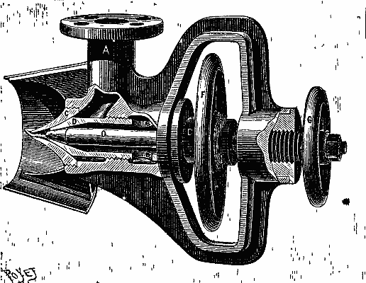
FIG. 1—THE DIETRICH PETROLEUM BURNER.
FIG. 1—THE DIETRICH PETROLEUM BURNER.
The regulation may be performed with the greatest ease. It is possible to instantly vary, together or separately, the steam and the petroleum. Under such circumstances, choking is not to be feared at the petroleum orifice, where, according to experiment, the thickness of the substance to be vaporized should not be less than 0.04 of an inch.
The regulation can be done very easily. You can quickly adjust the steam and the petroleum, either together or separately. In this situation, there's no need to worry about clogging at the petroleum opening, where experiments show that the thickness of the substance to be vaporized should be at least 0.04 inches.
The petroleum might evidently be made to enter at A and the steam at B; but one of the conclusions of the experiments cited is that the performance is better when the jet of steam surrounds the petroleum. It will be understood, in fact, that by this means not a particle of the liquid can escape vaporization and, consequently, combustion. Moreover, as the jet of petroleum is completely surrounded by steam its flow can be increased within the widest limits, and this, in certain cases, may prevent an obstruction without much diminishing the useful effect of the burner.
The oil can clearly be directed to enter at A and the steam at B; however, one of the findings from the experiments mentioned is that performance improves when the stream of steam envelops the oil. It’s clear that this way, not a drop of the liquid can escape vaporization and, therefore, combustion. Additionally, since the stream of oil is fully surrounded by steam, its flow can be increased significantly, which, in some cases, can prevent clogging without significantly reducing the effectiveness of the burner.
The apparatus is easily and rapidly taken apart. It it is only necessary to remove the nozzle, C, in order to partially clean it. It would even seem that the cleaning might be done automatically by occasionally reversing the flow of the steam and petroleum. However efficacious such a method might prove, the apparatus as we have described it can be very easily applied to any generator. Fig. 2 represents it as applied to the front of a furnace provided with two doors. A metallic box, with two compartments, is placed on one side of the furnace, and is provided with two stuffing boxes that are capable of revolving around the steam and petroleum pipes. The latter thus form the pivots of the hinge that allows of the play of the vaporizers and piping.
The device is simple and quick to disassemble. You just need to remove the nozzle, C, to clean it partially. It seems that cleaning could even be done automatically by occasionally reversing the flow of steam and petroleum. However effective this method may be, the device we've described can easily be attached to any generator. Fig. 2 shows it installed at the front of a furnace with two doors. A metal box with two compartments is placed on one side of the furnace and has two packing boxes that can rotate around the steam and petroleum pipes. These pipes act as the pivots of the hinge that enables the movement of the vaporizers and piping.
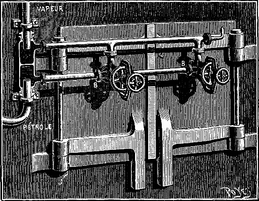
FIG. 2—THE BURNER APPLIED TO THE FURNACE OF A BOILER.
FIG. 2—THE BURNER APPLIED TO THE FURNACE OF A BOILER.
It was in this way that Mr. Dietrich arranged his apparatus in an experiment made upon a stationary boiler belonging to a Mr. Corpet. The experiment was satisfactory and led to the adoption of the arrangement shown in Fig. 3. The fire bridge is constructed of refractory bricks, and the majority of the grate bars are filled in with brick. The few free bars permit of the firing of the boiler and of access of air to the interior of the fire box. Under such circumstances, the combustion is very regular, the furnace does not roar, and the smoke-consuming qualities are perfect.
Mr. Dietrich set up his equipment for an experiment on a stationary boiler owned by Mr. Corpet. The experiment went well and resulted in the use of the setup shown in Fig. 3. The fire bridge is made of heat-resistant bricks, and most of the grate bars are filled with brick. The few open bars allow for firing the boiler and air to enter the firebox. In this setup, the combustion is very consistent, the furnace operates quietly, and the smoke is efficiently burned off.
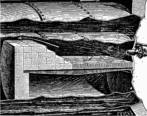
FIG. 3—APPLICATION OF THE BURNER TO A RETURN FLAME BOILER.
FIG. 3—APPLICATION OF THE BURNER TO A RETURN FLAME BOILER.
In the experiment on the Flamboyante, the boiler was provided with but one apparatus, and the grate remained covered with a layer of ignited coal that had been used for firing up in order to obtain the necessary pressure of steam to set the vaporizer in operation. This ignited coal appeared to very advantageously replace the refractory bricks, the role of which it exactly fulfilled. It has been found well, moreover, to break the flames by a few piles of bricks in the furnace, in order to obtain as intimate a mixture as possible of the inflammable gases.
In the experiment on the Flamboyante, the boiler was equipped with only one device, and the grate was covered with a layer of burning coal that had been used to heat up in order to achieve the necessary steam pressure to activate the vaporizer. This burning coal seemed to effectively replace the refractory bricks, serving the same purpose perfectly. Additionally, it was found to be beneficial to break the flames with a few stacks of bricks in the furnace to achieve the closest possible mixture of the flammable gases.
It is to be remarked that firing up in order to obtain the necessary steam at first is a drawback that might be surmounted by using at the beginning of the operation a very small auxiliary boiler. The main furnace would then be fired by means of say a wad of cotton. But, in current practice, if a grate and fire be retained, the firing will perhaps be simpler.
It’s worth noting that getting started to generate the necessary steam initially is a challenge that could be overcome by using a small auxiliary boiler at the beginning of the operation. The main furnace could then be ignited with something like a wad of cotton. However, in current practice, if a grate and fire are kept, the process of firing might be a bit easier.
With but one apparatus, the pressure in the Flamboyante's boiler rose in a few minutes from 6 to 25 pounds, and about a quarter of an hour after leaving the wharf the apparatus had been so regulated that there was no sign of smoke. This property of the Dietrich burner proceeds naturally from the use of a jet of steam to carry along the petroleum and air necessary for combustion. It is, in fact, an Orvis smoke consumer transformed, and applied in a special way.
With just one device, the pressure in the Flamboyante's boiler increased in a few minutes from 6 to 25 pounds, and about fifteen minutes after leaving the dock, the device was adjusted so that there was no visible smoke. This feature of the Dietrich burner comes naturally from using a steam jet to mix the petroleum and air needed for combustion. Essentially, it's a modified Orvis smoke consumer used in a unique way.
It must be added that the regulating requires a certain amount of practice and even a certain amount of time at every change in the boat's running. So it is well to use two, and even three, apparatus, of a size adapted to that of the boiler. The regulation of the furnace temperature is then effected by extinguishing one or two, or even three, of the apparatus, according as it is desired to slow up more or less or to come to a standstill.
It should be noted that controlling the furnace requires some practice and a bit of time whenever there's a change in the boat's operation. So, it's a good idea to use two or even three devices that are suitable for the size of the boiler. You can adjust the furnace temperature by turning off one, two, or even three of the devices, depending on whether you want to slow down more or less or to stop completely.
The oil used by Mr. De Dosme on his yacht comes from Comaille, near Antun. The price of it is quite low, and, seeing the feeble consumption (from 33 to 45 lb. for the yacht's boiler), it competes advantageously with the coal that Mr. De Dosme was formerly obliged to use.—La Nature.
The oil that Mr. De Dosme uses on his yacht comes from Comaille, near Antun. It's pretty cheap, and considering the low consumption (between 33 and 45 lb. for the yacht's boiler), it competes well against the coal that Mr. De Dosme had to use before.—La Nature.
[Continued from SUPPLEMENT, No. 622, page 9935.]
[Continued from SUPPLEMENT, No. 622, page 9935.]
THE CHANGE OF GAUGE OF SOUTHERN RAILROADS IN 1886.1
By C.H. HUDSON.
Many of the wheels that were still in use with the long hub were put into a lathe, and a groove was cut an inch and a half back from the face, leaving our cast collar, which was easily split off as before. (Fig. 24.)
Many of the wheels that were still in use with the long hub were placed in a lathe, and a groove was cut an inch and a half back from the face, leaving our cast collar, which was easily split off as before. (Fig. 24.)
With tender wheels, as with our car wheels, the case was different. Originally, the axle for the 5 ft. gauge was longer than for the 4 ft. 9 in.; but latterly the 5 ft. roads had used a great many master car builders' axles for the 4 ft. 9 in. gauge, namely, 6 ft. 11¼ in. over all, thus making the width of the truck the same as for 4 ft. 9 in. gauge. To do this a dished wheel, or rather a wheel with a greater dish by 1½ in. than previously used, was needed, so that the tread of the wheel could be at its proper place. (See Fig. 25.) There were, of course, many of the wheels with small dish and long axles still in use. Their treatment, however, when the day of change came, did not vary from that of the short axle.
With tender wheels, like our car wheels, the situation was different. Initially, the axle for the 5 ft. gauge was longer than for the 4 ft. 9 in.; but recently, the 5 ft. roads had incorporated many master car builders' axles meant for the 4 ft. 9 in. gauge, specifically 6 ft. 11¼ in. overall, thereby matching the truck width to that of the 4 ft. 9 in. gauge. To achieve this, a dished wheel, or rather a wheel with a 1½ in. deeper dish than previously used, was necessary, so that the tread of the wheel could be appropriately positioned. (See Fig. 25.) Naturally, many wheels with a shallow dish and long axles were still in use. However, their adjustment, when the time for change arrived, was no different from that of the short axle.
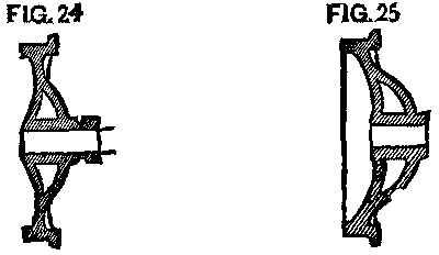
FIG. 24 and FIG. 25
FIG. 24 and FIG. 25
It had been the rule for some years that all axles should be turned back 1½ in. further than needed; but unfortunately the rule had not been closely followed, and many were found not to be so turned. To make the matter worse, quite a number of the wheels were found to have been counterbored about ½ in. deep at the back end, and the axle turned up to fit this counterbore; a good idea to prevent the running in, in case the wheel worked loose, but bad from the standpoint of a change of gauge. In such cases the wheels had to be started off before the axle could be turned back, so that the wheels could be pushed on in their proper position. (Fig. 26.)
It had been the rule for several years that all axles should be turned back 1½ inches further than needed; however, unfortunately, this rule hadn't been closely followed, and many were found not to meet this requirement. To make matters worse, quite a few of the wheels were discovered to have been counterbored about ½ inch deep at the back end, and the axle was adjusted to fit this counterbore. This was a good idea to prevent running in if the wheel became loose, but it was problematic from the perspective of changing the gauge. In these situations, the wheels had to be removed before the axle could be turned back so that the wheels could be properly repositioned. (Fig. 26.)
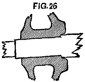
FIG. 26
FIG. 26
If the work was done where they had a lathe large enough to swing a pair of wheels, they were pressed off but half an inch, the wheels swung in the lathe, the axles turned back 1½ in., and the wheels then pressed on 2 in. or 1½ in. inside of their first position.
If the job was done in a shop that had a lathe big enough to handle a pair of wheels, they were pushed off by half an inch. The wheels rotated in the lathe, the axles were turned back 1½ inches, and then the wheels were pushed on 2 inches or 1½ inches from their original position.
Where no large lathe was in use, the wheels came entirely off before the axles could be turned back. The work in the former case was both the quicker and the cheaper. Where the large lathes were used they were either set down into the floor, so a pair of wheels would easily roll into place, or a raised platform was put before the lathe, with an incline up which the wheels were rolled and then taken to the lathe. These arrangements were found much quicker and cheaper than to hoist the wheels up, as is usually done.
Where there wasn't a large lathe in use, the wheels completely came off before the axles could be adjusted. The work in that situation was both faster and cheaper. When large lathes were used, they were either installed flush with the floor, so a pair of wheels could easily roll into place, or a raised platform was placed in front of the lathe, with a slope where the wheels were rolled up and then brought to the lathe. These setups were found to be much quicker and cheaper than lifting the wheels up, as is typically done.
In pressing the wheels on, where the axles had previously been turned back, much trouble was at first experienced because of the rust that had gathered upon the turned part behind the wheel, forming a ridge over or upon which the wheel must be pushed. Some of the roads, at the start, burst 10 or 15 per cent. of the wheels so pressed on. By saturating this surface with coal oil, however, it was found that the rust was easily removed and little trouble was had. It was found, sometimes, that upon axles newly turned back a careless workman would leave a ridge at the starting point of the turning. Frequently also the axles were a little sprung, so that the new turning would be a little scant upon one side when compared with the old surface, and upon the opposite side a little full. As an indication that these difficulties were overcome as they appeared, I will say that upon our line only 202 wheels burst out of nearly 27,000 pressed on—an exceedingly small percentage.
In pressing the wheels on, where the axles had previously been turned back, we initially faced a lot of trouble because of the rust that had built up on the turned part behind the wheel, creating a ridge that the wheel had to be pushed over. Some of the roads experienced a 10 or 15 percent failure rate with the wheels that were pressed on. However, by soaking this surface with coal oil, we found that the rust was easily removed, resulting in much less trouble. Sometimes, we noticed that on newly turned axles, a careless worker would leave a ridge at the starting point of the turning. Often, the axles were slightly bent, which meant that the new turning would be a little too short on one side compared to the old surface and slightly too long on the opposite side. As proof that we overcame these challenges as they came up, I can say that on our line, only 202 wheels burst out of nearly 27,000 pressed on—an incredibly small percentage.
After the change upon the early roads they were troubled for weeks with hot boxes, caused, as we believed, by the changing of brasses. A brass once fitted to a journal will work upon it without trouble, but when placed upon some other journal will probably not fit. If the journal had been worn hollow (and it was surprising to see how many were so worn), the brass would be found worn down to fit it. (See Fig. 27. Exaggerated, of course.)
After the changes made to the early roads, they dealt with hot boxes for weeks, which we believed were caused by the adjustment of brasses. A brass that’s originally fitted to a journal works fine, but when put on a different journal, it probably won’t fit. If the journal had worn a groove (and it was surprising to see how many were worn this way), the brass would end up being worn down to match it. (See Fig. 27. Exaggerated, of course.)
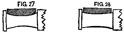
FIG. 27 and FIG. 28
FIG. 27 and FIG. 28
The next wheel may have an axle worn little or none. (See Fig. 28)
The next wheel might have an axle that’s barely worn or not worn at all. (See Fig. 28)
Now, if these brasses are exchanged, we have the conditions as shown in Figs. 29 and 30, and we must expect they will heat. The remedy was simply to keep each brass upon its own journal. To do this the brasses were fastened to the axle by a piece of small wire, and went with it to the lathe and press. When its truck was reached, the brass was there with its journal. Worn-out brasses, of course, could not be put in, and new ones were substituted. The little trouble from that source that followed the change showed the efficacy of the remedy.
Now, if these brass pieces are swapped, we have the conditions shown in Figs. 29 and 30, and we can expect them to heat up. The solution was simple: keep each brass on its own journal. To do this, the brass pieces were secured to the axle with a small piece of wire, allowing them to go with it to the lathe and press. Once at the truck, the brass was there with its journal. Of course, worn-out brass pieces couldn't be reused, so new ones were put in. The minor issues that arose after the change demonstrated the effectiveness of the solution.
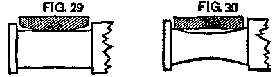
FIG. 29 and FIG. 30
FIG. 29 and FIG. 30
The manner in which the tires of engines were to be changed, when the final day came, was a serious question. The old-fashioned fire upon the ground could not be thought of. The M. & O. had used a fire of pine under the wheel, which was covered by a box of sheet iron, so arranged that the flame and heat would be conveyed around the tire, and out at an aperture at the top. (Fig. 31.) Many thought this perfect, while others were not satisfied, and began experiments for something better. A device for using gas had been patented, but it was somewhat complicated, as well as expensive, and did not meet with general favor. A very simple device was soon hit upon. A two inch pipe was bent around in a circle a little larger than the outer rim of the wheel. Holes 1/10 in. in diameter and 3 or 4 in. apart were drilled through the pipe on the inside of the circle. To this pipe was fastened another with a branch or fork upon it. To one branch or fork was connected a gas pipe from the meter, while to the other was connected a pipe from an air pump. With the ordinary pressure of city gas upon this pipe it was found that the air pump must keep an air pressure of 40 pounds, that the air and gas might mix properly at the branch or fork, so we could get the best combustion and most heat from our "blowpipe," for such it was. (Fig. 32.)
The way to change the tires of engines on the final day was an important issue. Using the traditional fire on the ground was out of the question. The M. & O. had used a fire of pine under the wheel, which was covered by a sheet metal box designed to channel the flame and heat around the tire and out through an opening at the top. (Fig. 31.) Many thought this method was perfect, while others were not satisfied and started experimenting for something better. A gas-based device had been patented, but it was somewhat complicated and pricey, and it didn't gain widespread approval. A much simpler solution was quickly discovered. A two-inch pipe was bent into a circle slightly larger than the outer rim of the wheel. Holes measuring 1/10 inch in diameter and spaced 3 to 4 inches apart were drilled through the inside of the pipe. Another pipe was attached to this one, with a branch or fork added. One branch was connected to a gas pipe from the meter, while the other was linked to a pipe from an air pump. With the normal pressure of city gas on this pipe, it was found that the air pump needed to maintain an air pressure of 40 pounds to ensure the proper mixing of air and gas at the branch or fork, so we could achieve the best combustion and maximum heat from our "blowpipe," as it was called. (Fig. 32.)
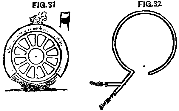
FIG. 31 and FIG. 32
FIG. 31 and FIG. 32
We were able to heat a tire so it could be moved in ten to twenty minutes, and the machine may be said to have been satisfactory.
We could heat a tire to make it movable in ten to twenty minutes, and the machine worked well.
Gas, however, was not to be had at all places where it would be necessary to change tires, and the item of cost was considerable.
Gas, however, wasn’t available at all the places where it would be necessary to change tires, and the cost was significant.
To reach a result as good, if possible, experiments were begun with coal oil (headlight oil). They were crude and unsatisfactory at first, but soon success was reached.
To achieve a result as good as possible, experiments started with coal oil (headlight oil). They were rough and not very satisfying at first, but soon they found success.
A pipe was bent to fit the lower half of a wheel pretty closely and then turned back under itself about the diameter of the pipe distant from it. This under part had holes 1/10 in. diameter and 3 or 4 in. apart drilled upon its upper side or under the upper pipe. Connected with the upper pipe at its center was a pipe which ran to one side and up to the can containing the kerosene. Between the can and the pipe under the wheel was a stop cock, by which the flow of oil could be controlled.
A pipe was bent to fit closely around the lower half of a wheel and then turned back under itself about the diameter of the pipe away from it. This underside had holes 1/10 in. in diameter and spaced 3 or 4 in. apart drilled into its upper side or under the upper pipe. Connected to the center of the upper pipe was another pipe that ran to one side and up to the can holding the kerosene. Between the can and the pipe under the wheel was a stopcock that could control the flow of oil.
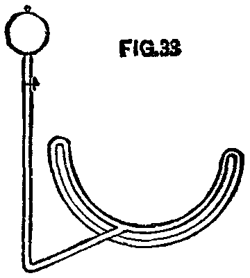
FIG. 33
FIG. 33
To use the device, open the cock and let a small amount of oil flow; apply fire to the pipe under the wheel, and the oil in the upper pipe is converted into gas, which flows out of the small holes in the lower pipe, takes fire, and heats not only the tire, but the upper pipe, thus converting more oil into gas. We had here a lot of blue flame jets and the same result as with gas, but at less cost. We had also a machine that was inexpensive and easily handled anywhere. Boxes were placed over the upper parts of the wheels, that the heat might pass closely to the tire. This device was extensively used by our people, and with great satisfaction. In one way care had to be taken, viz.: That in starting the fire it did not smoke and cover the tire with carbon or "lampblack," which is a non-conductor of heat.
To use the device, open the valve and let a small amount of oil flow; light the pipe beneath the wheel, and the oil in the upper pipe turns into gas, which escapes through the small holes in the lower pipe, ignites, and heats not just the tire but also the upper pipe, resulting in even more oil being converted into gas. We had a lot of blue flame jets and got the same outcome as with gas, but at a lower cost. We also had a machine that was affordable and easy to handle anywhere. Boxes were placed over the upper parts of the wheels so that the heat would closely reach the tire. This device was widely used by our people, and with great satisfaction. There was one caveat: care had to be taken that when starting the fire, it didn’t produce smoke that would coat the tire with carbon or "lampblack," which doesn’t conduct heat.
Experiments were made with air forced through gasoline, and with oil heated in a can to form gas. There was more danger in either of these than with our blowpipe device, and no better results were obtained, though the cost was greater.
Experiments were conducted using air pushed through gasoline and with oil heated in a can to create gas. Both methods were more dangerous than our blowpipe device, and they didn’t yield better results, even though they were more expensive.
With the change of the wheels, the brakes had to be changed the same amount, that is, each one set in 1½ in. This it was thought would either require new hangers or a change in the head or shoe in some way. We found that the hangers could easily be bent without removal. Fig. 34 shows three hangers after passing through the bending process. A short lever arranged to clasp the hanger just below the point, A, was the instrument; a forked "shore" is now placed, with the fork, against the point, A, and the other end against the car sill; press down on the lever and you bend the hanger at A; lower the lever to a point just below B, reverse the process, and you have the bend at B; the whole thing taking less than two minutes per hanger. A new bolt hole, of course, has been bored in the brake beam 1½ in. inside the old hole. It takes but a short time after this to change the position of the head and shoe.
With the change of the wheels, the brakes also had to be adjusted by the same amount, specifically, each needed to be set 1½ in. It was thought that this would require either new hangers or some adjustment to the head or shoe. We discovered that the hangers could easily be bent without removing them. Fig. 34 shows three hangers after the bending process. A short lever designed to grip the hanger just below point A was used as the tool; a forked "shore" is now placed, with the fork against point A, and the other end against the car sill. By pressing down on the lever, you can bend the hanger at A; then lower the lever to just below B, reverse the process, and you’ll have the bend at B. The entire process takes less than two minutes per hanger. A new bolt hole has, of course, been drilled in the brake beam 1½ in. inside the old hole. It takes only a short time after this to adjust the position of the head and shoe.
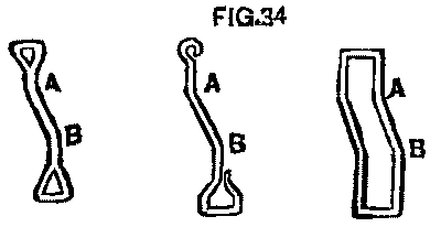
FIG. 34
FIG. 34
Before the day of change, a portion of the spikes were drawn from the inside of the rail to be moved, and spike set 3 in. inside of the rail. As a rule two spikes were drawn and the third left. At least every third spike was set for the new gauge, and in some cases every other one.
Before the day of change, some of the spikes were pulled from inside the rail to be moved, and spike set was 3 inches inside the rail. Typically, two spikes were removed and the third one was left in place. At least every third spike was set for the new gauge, and in some instances, every other spike was adjusted.
There were several devices with which to set the spike. A small piece of iron 3 in. wide was common, and answered the purpose well. This had a handle, sometimes small, just large enough for the hand to clasp, while others had a handle long enough for a man to use it without stooping down. (See Figs. 35 and 36.) Another device is shown in Fig. 37, so arranged that the measurements were made from the head of the other rail. This was liked best, and, it is thought, gave the best results, as the moved rail was more likely to be in good line than when the measurements were taken from the flange.
There were several tools to set the spike. A small piece of iron 3 inches wide was common and worked well for the job. This had a handle, sometimes small, just big enough for a hand to grip, while others had a handle long enough for a person to use it without bending down. (See Figs. 35 and 36.) Another tool is shown in Fig. 37, designed so that measurements were taken from the head of the other rail. This was preferred, and it’s believed to give the best results, as the moved rail was more likely to be aligned properly than when measurements were taken from the flange.
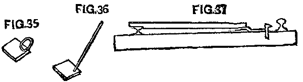
FIG. 35, FIG. 36 and FIG. 37
FIG. 35, FIG. 36 and FIG. 37
It was intended that great care should be taken in driving the spikes, that they were in the proper place, square with the rail, and left sticking up about an inch.
Great care was meant to be taken when driving the spikes, ensuring they were in the right spot, aligned with the rail, and left sticking up about an inch.
The ties, of course, were all adzed down before the day of change.
The ties, of course, were all shaved down before the day of change.
"Handspikes" were originally used to throw the rails, as were lining bars.
"Handspikes" were originally used to move the rails, just like lining bars.
We found, however, that small "cant hooks" were more easily handled and did better work. The first were made like Fig. 38, with a spike in the end of a stick, while the hook was fastened with a bolt about 10 or 12 inches above the foot.
We found, however, that small "cant hooks" were easier to handle and worked better. The first ones were made like Fig. 38, with a spike at the end of a stick, while the hook was attached with a bolt about 10 or 12 inches above the foot.
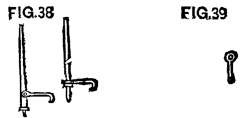
FIG. 38 and FIG. 39
FIG. 38 and FIG. 39
We afterward made them of a 1¼ in. rod, 3½ ft. long, pointed at one end, with a ring shrunk on 1 ft. from the bottom. Then the hook was made with an eye, as shown in Fig. 39, which slipped down over the top of the main rod. This was simple and cheap, and the iron was to be used for repair purposes when this work was done.
We later created them from a 1¼ in. rod, 3½ ft. long, pointed at one end, with a ring attached 1 ft. from the bottom. Then the hook was made with an eye, as shown in Fig. 39, which slid down over the top of the main rod. This design was straightforward and inexpensive, and the iron would be used for repairs once this work was complete.
Upon the system with which the writer was connected we had some branches where we could experiment upon the moving of the rail. Between Selma and Lauderdale the traffic was light, and at Lauderdale it connected with the Mobile & Ohio Railroad, which was narrow, and to which all freight had to be transferred, either by hoisting the cars or by handling through the house. By changing our gauge we would simply change the point of transfer to Selma. Here was a chance to experiment upon one hundred miles and cause little trouble to traffic. We could see the practical workings of our plans, and, at the same time, leave less to do on the final day. Upon the 20th of April we did this work. It had been our plan to do it somewhat earlier, but floods prevented.
On the system the writer was connected to, we had some branches where we could test the moving of the rail. Between Selma and Lauderdale, the traffic was light, and in Lauderdale, it connected with the Mobile & Ohio Railroad, which was narrow, so all freight had to be transferred, either by lifting the cars or handling them through a building. By changing our gauge, we would just shift the transfer point to Selma. This was an opportunity to experiment over one hundred miles with minimal disruption to traffic. We could observe how our plans worked in practice while also reducing the final workload. We completed this work on April 20th. Our intention had been to do it a bit earlier, but floods got in the way.
Most of the rail was old chair iron, short, and consequently more time was used in making the change than would have been required had our work been on fishplate rail. Our sections here were about eight miles long, and we arranged our men on the basis blocked out by the committee, viz., 24 to 26 men to the section, consisting of 6 spike pullers, 4 throwing rails, 12 spikers, 2 to push the cars and carry water.
Most of the rail was old chair iron, short, and as a result, it took more time to make the change than it would have if we had been working with fishplate rail. Our sections here were about eight miles long, and we organized our team based on the plan set by the committee, which called for 24 to 26 men per section. This included 6 spike pullers, 4 throwing rails, 12 spikers, and 2 to push the cars and carry water.
We soon found 5 ft. cars useless, and threw them into the ditch to be picked up at some future time.
We quickly realized that 5 ft. cars were useless and tossed them into the ditch to be picked up later.
The men were spread out so as not to be in each other's way, and when the organization was understood and conformed to, it worked well. One gang changed 5 miles in 5 hours and 10 minutes, including a number of switches. We found, however, and it was demonstrated still more strongly on later work, that after 5 or 6 miles the men began to lag.
The men were spaced out to avoid getting in each other's way, and once everyone understood and followed the setup, it functioned effectively. One group covered 5 miles in 5 hours and 10 minutes, which included several stops. However, we noticed, and it was confirmed even more clearly in later tasks, that after about 5 or 6 miles, the men started to slow down.
We believed we had the best results when we had sections of about that length.
We thought we achieved the best results when our sections were about that length.
It was arranged that two sections, alternately, commenced work together at one point, working from each other and continuing until the force of another section was met, working from the opposite direction.
It was arranged that two teams would start working together from one point, moving toward each other until they met the force of another team coming from the opposite direction.
The foreman in charge was expected to examine the work and know that all was right. The push car which followed was a good test as to gauge.
The foreman in charge was expected to check the work and ensure that everything was correct. The push car that followed was a reliable way to measure it.
A work train was started from each end with a small force (20 or 25 men) to run over the changed track. This train, of course, had been changed on a previous day to be ready for this work.
A work train was set up from both ends with a small crew (20 or 25 men) to travel over the altered track. This train had, of course, been modified the day before to be prepared for this task.
If a force was overtaken by this train with its work not done, the men on the train were at once spread out to aid in its completion. This done, the train ran on.
If the train overtook a force that hadn’t finished its work, the men on the train immediately spread out to help complete it. Once that was done, the train continued on its way.
Not until this was done was a traffic train allowed to pass over the track. The same rule was followed upon all the work.
Not until this was done was a traffic train allowed to pass over the track. The same rule was applied to all the work.
Upon the final day it was required that upon all high trestles and in tunnels the track should be full-spiked before being left or a train let over. This took extra time and labor, and possibly was not necessary; but it was a precaution on the side of safety.
On the last day, it was necessary for all high trestles and tunnels to be fully spiked before leaving or letting a train go over. This took additional time and effort, and it might not have been needed; but it was a safety precaution.
Upon the day of the change of the Alabama Central Division (Selma to Lauderdale), superintendents of other divisions, with their road masters, supervisors, master mechanics and many section foremen, were sent over to see the organization and work and the preparations that had been made. Many of them lent a helping hand in the work. They saw here in practice what had only been theory before.
On the day of the change of the Alabama Central Division (Selma to Lauderdale), superintendents from other divisions, along with their road masters, supervisors, master mechanics, and several section foremen, came over to check out the organization, work, and preparations that had been made. Many of them pitched in and helped with the tasks. They witnessed firsthand what had previously only been theoretical.
About a week before the general change that portion of the road between Rome, Ga., and Selma, Ala., about 200 miles, was changed, and again men from other divisions were sent to see and aid in the work. So when the final day came, the largest possible number of men were able to work understandingly.
About a week before the general change, that section of the road between Rome, Ga., and Selma, Ala., which is about 200 miles long, was modified, and once more, men from other divisions were sent to observe and assist with the work. So when the final day arrived, the maximum number of men were able to work effectively together.
On the last day of May the Memphis & Charleston, Knoxville & Ohio, and North Carolina branch were changed, and on June 1 the line from Bristol to Chattanooga and Brunswick.
On the last day of May, the Memphis & Charleston, Knoxville & Ohio, and North Carolina branches were changed, and on June 1, the line from Bristol to Chattanooga and Brunswick.
Other roads changed their branch lines a day or two before the 1st of June; but the main lines, as a rule, were changed on that day.
Other roads changed their branch lines a day or two before June 1st; but the main lines, as a rule, were changed on that day.
It was a small matter to take care of the cars and arrange the train service so there should be no hitches. It was not expected that connections would move freight during the 48 hours prior to the change, and these days were spent in clearing the road of everything, and taking the cars to the points of rendezvous. All scheduled freight trains were abandoned on the day prior to the change, and only trains run to such points.
It was a simple task to manage the cars and set up the train service to avoid any issues. It wasn’t anticipated that connections would transport cargo during the 48 hours leading up to the change, so this time was used to clear the road of anything unnecessary and bring the cars to the meeting points. All planned freight trains were canceled the day before the change, and only trains went to those points.
Upon the East Tennessee system these points were Knoxville, Rome, Atlanta, Macon, Huntsville, and Memphis, and to these points all cars must go, loaded or empty, and there they were parked upon the tracks prepared for the purpose. Passenger trains were run to points where it had been arranged to change them, generally to the general changing point.
On the East Tennessee system, these locations were Knoxville, Rome, Atlanta, Macon, Huntsville, and Memphis. All cars, whether loaded or empty, had to go to these locations and were parked on the tracks set aside for that purpose. Passenger trains were operated to the designated transfer points, usually to the main transfer hub.
Most of the Southern roads have double daily passenger service. Upon all roads one of these trains, upon the day of change, was abandoned, and upon some all. Some, even, did not run till next day.
Most of the Southern roads have two daily passenger services. On all the roads, one of these trains was canceled on the changeover day, and on some roads, all of them were. Some even didn't operate until the next day.
We were able to start the day trains out by 10 or 11 o'clock A.M., and put them through in fair time. Of course, no freights were run that day, and the next day was used in getting the cars which had been changed out of the parks and into line. So our freight traffic over the entire South was suspended practically three days.
We managed to get the day trains running by 10 or 11 A.M. and had them on schedule. Naturally, no freight trains operated that day, and the following day was spent getting the cars that had been moved out of storage back in line. So, our freight traffic across the entire South was effectively halted for about three days.
The work of changing was to commence at 3:30 A.M., but many of the men were in position at an earlier hour, and did commence work as soon as the last train was over, or an hour or so before the fixed time. Half-past three A.M., however, can be set down as the general hour of commencement.
The work of changing was set to start at 3:30 A.M., but many of the men were already in place earlier and began working as soon as the last train passed or about an hour before the scheduled time. However, 3:30 A.M. can be noted as the general start time.
For five or six hours in the cool morning the work went on briskly, the men working with much more than ordinary enthusiasm. But the day was warm, and after 9 or 10 A.M. it began to lag. All was done, however, before the day was over, and safe, so that trains could pass at full speed.
For five or six hours in the cool morning, work continued energetically, with the men showing much more enthusiasm than usual. But the day got warm, and after 9 or 10 A.M., progress began to slow down. Everything was completed before the day ended, and it was done safely, allowing trains to pass at full speed.
The men all received $1.50 for the work, whether it was finished early or late in the day, and were paid that afternoon as soon as the work was done. Tickets were given the men, which the nearest agent paid, remitting as cash to the treasurer.
The men all got $1.50 for their work, whether they finished early or late in the day, and they were paid that afternoon as soon as their work was done. They received tickets, which the nearest agent cashed in and forwarded to the treasurer.
On some lines it was deemed best to offer prizes to those who got through first.
On some routes, it was considered best to offer prizes to those who finished first.
Reports showed some very early finishes. But the facts seem to have been that under such encouragement the men were apt to pull too many spikes before the change and put too few in while changing. They were thus reported through early, but their work was not done, and they took great chances.
Reports indicated some very early completions. However, it appears that with such motivation, the workers tended to remove too many spikes before the change and insert too few during the transition. As a result, they were reported as finished early, but their work wasn’t complete, and they were taking significant risks.
It was by most considered unwise to offer such prizes, preferring to have a little more time taken and be sure that all was safe. Such lines seemed to get their trains in motion with as much promptness as others. This, with freedom from accident, was the end sought.
It was seen as unwise by most to offer such prizes, opting instead for a bit more time to ensure everything was safe. These lines appeared to get their trains moving just as quickly as the others. This, along with avoiding accidents, was the goal they aimed for.
It was found after the work had been done that there had been little inaccuracies in driving the gauge spike, to which the rail was thrown, probably from various causes. The rail to be moved may not always have been exactly in its proper place, and then the template in the hurry may not have been accurately placed, or the spike may have turned or twisted.
It was discovered after the work was completed that there were some minor inaccuracies in driving the gauge spike, which caused the rail to be misaligned, likely due to several factors. The rail that needed to be moved might not have always been in its exact position, and in the rush, the template may not have been positioned accurately, or the spike could have turned or twisted.
Whatever was the cause, it was found that frequently the line on the moved side was not perfect, and, of course, many spikes had to be drawn and the rail lined up and respiked. The more careful the work had been done, the less of this there was to do afterward. With rough track this was least seen. The nearer perfect, the more noticeable it was.
Whatever the reason, it became clear that often the alignment on the shifted side wasn't right, which meant many spikes had to be removed and the rail adjusted and re-spiked. The more careful the initial work was, the less there was to fix later. With poorly maintained tracks, this issue was less visible. The closer to perfect the track was, the more obvious the mistakes became.
Of course, we all planned to get foreign cars home and have ours sent to us. But when the interchange stopped, we found we had many foreign cars, which, of course, had to be changed. This subject had come up in convention and it had been voted to charge three dollars per car when axles did not need turning, and five dollars where they did. By comparison with the cost of changing, as shown in this paper, it will be seen that to our company, at least, there was no loss at these figures.
Of course, we all planned to have foreign cars shipped home and get ours sent to us. But when the interchange stopped, we realized we had many foreign cars that needed to be changed. This topic came up at the convention, and it was decided to charge three dollars per car when axles didn’t need to be turned, and five dollars when they did. Compared to the cost of changing, as shown in this report, it’s clear that there was no loss for our company at these rates.
The following tables will explain the work done upon the Louisville & Nashville and East Tennessee, Virginia & Georgia systems.
The following tables will explain the work done on the Louisville & Nashville and East Tennessee, Virginia & Georgia systems.
It is to be regretted that the writer has not at hand information regarding other roads, that fuller statements and comparisons might be made and the showings be of greater value.
It’s unfortunate that the writer doesn’t have information about other roads, as more complete details and comparisons could be made, making the findings more valuable.
The figures of the Mobile & Ohio are added, having been compiled from the annual report of that road.
The numbers for the Mobile & Ohio are included, based on the annual report from that railway.
MOBILE & OHIO RAILROAD.
MOBILE & OHIO RAILROAD.
(Compiled from Annual Report.)
(Compiled from Annual Report.)
| Number Changed. | Cost of Labor. | Cost of Material. | Total Cost. | Average Cost. | |
|---|---|---|---|---|---|
| Engines and tenders. | 47 | $ 8,031.42 | $ 7,276.86 | $15,308.28 | $325.70 |
| Pass., bag., ex. cars. | 55 | 439.37 | 104.25 | 542.62 | 9.87 |
| Freight cars, 1,361. Freight trucks, 107½. | 1,468½ | 5,719.03 | 739.57 | 6,458.60 | 4.40 |
| Lever and push cars. | 143 | 1,427.55 | 476.93 | 1,904.48 | 13.32 |
| Miles. | |||||
| Track (inc. sidings). | 583.5 | 17,109.53 | 7,275.14 | 24,384.87 | 41.79 |
| Bridges. | 583.5 | 1,896.60 | 190.00 | 2,086.60 | 3.58 |
| Track tools. | 583.5 | 170.72 | 1,405.74 | 1,576.46 | 2.70 |
| Shop tools. | 583.5 | 419.70 | 2,982.90 | 3,402.60 | 5.83 |
| Temp. side tracks. | 12.09 | 1,958.94 | 372.37 | 2,331.31 | 192.83 |
| Switching cars. | 1,398.18 | 16.50 | 1,414.68 | ||
| Car hoists. | 2,499.38 | 4,419.34 | 6,918.72 | ||
| Total cost. | $41,069.42 | $25,259.60 | $66,329.02 | ||
| Total average cost per mile. | $113.68 | ||||
LOUISVILLE & NASHVILLE RAILROAD.
LOUISVILLE & NASHVILLE RAILROAD.
(Compiled from Annual Report.)
(Compiled from Annual Report.)
| Miles of track | —Main line | 1,893.7 | ||
| —Side track | 196.3 | |||
| ———— | 2,090.0 | |||
| Track. | Total. | Cost per Mile. | ||
|---|---|---|---|---|
| Section labor | —Before day of change | $28,106.60 | ||
| —On day of change | 20,090.42 | |||
| —After day of change | 19,713.19 | |||
| ———— | $67,910.21 | $32.49 | ||
| Carpenter labor | 3,799.19 | 1.82 | ||
| Spikes | 20,873.70 | 9.99 | ||
| Switches | 6,331.85 | 3.03 | ||
| Tools | 2,749.50 | 1.31 | ||
| Hand cars and sundries | 5,691.39 | 2.72 | ||
| Total | $107,855.84 | $51.36 | ||
| Equipment. | ||||
| Number. | Total. | Average Cost. | ||
| Locomotives | 264 | $53,480.98 | $202.58 | |
| Cars (300 of these passenger—3.5%) | 8,537 | 49,577.20 | 5.81 | |
| Total cost | $210,414.02 | |||
| Total average cost per mile | $100.67 | |||
EAST TENNESSEE, VIRGINIA & GEORGIA SYSTEM.
EAST TENNESSEE, VIRGINIA & GEORGIA SYSTEM.
| Number Changed. | Cost of Labor. | Cost of Material. | Total Cost. | Average Cost. | |
|---|---|---|---|---|---|
| Engines and tenders. | 180 | $ 8,227.47 | $ 2,904.30 | $ 11,131.77 | $ 61.82 |
| Pass., bag., and mail cars. | 168 | 734.93 | 59.67 | 794.60 | 4.73 |
| Freight cars and cabooses. | 5,175 | 17,425.57 | 1,224.08 | 18,649.65 | 3.60 |
| M. of W. cars. | 439 | 2,038.44 | 549.47 | 2,587.91 | 5.89 |
| Miles Track. | |||||
| Track (inc. sidings). | 1,532.7 | 27,718.17 | 40,912.09 | 68,630.26 | 44.78 |
| Bridges. | 1,532.7 | 1,808.57 | 200.00 | 2,008.57 | 1.31 |
| Track tools. | 1,532.7 | 194.48 | 2,573.83 | 2,768.31 | 1.80 |
| Storage tracks, inc. taking up. | 37.02 | 9,825.41 | 1,481.59 | 11,307.00 | 305.44 |
| Shop tools. | 472.20 | 2,728.30 | 3,200.50 | ||
| Total cost. | $68,445.24 | $52.633.33 | $121,078.57 | ||
| Total average cost per mile. | $ 79.06 | ||||
| Axles condemned | 577 |
| Wheels condemned | 754 |
| Wheels burst | 202 |
| New axles used | 1,102 |
| New wheels used | 2,783 |
| Axles turned back | 8,316 |
| Wheels pressed on without turning axle | 23,952 |
| New brasses used | 10,723 |
| Cars narrowed (not including lever or push cars) | 5,343 |
| Engines narrowed | 180 |
| Average cost of new centers and crank pins, etc | $264.46 |
| Average cost of cutting off hub and pressing wheels and new pins | 130.67 |
| Average cost of pressing old tires on old centers | 29.08 |
| Average cost of pressing old tires on broad centers | 31.83 |
| Average cost of labor putting on new tires | 22.94 |
COMPARATIVE STATEMENT OF AVERAGE COST OF VARIOUS ITEMS OF WORK.
COMPARATIVE STATEMENT OF AVERAGE COST OF DIFFERENT WORK ITEMS.
| M. & O. R.R. | L. & N. R.R. | E.T.,V. & G. R.R. | Average. | |
|---|---|---|---|---|
| Engines and tenders—per engine | $325.70 | $202.58 | $61.82 | $196.70 |
| Pass., bag., and ex. cars—per car | 9.87 | 25.81 | 4.73 | 6.80 |
| Freight cars, per car | 4.40 | 35.81 | 3.60 | 4.60 |
| M. of W. cars, per car | 13.32 | 2.72 | 5.89 | 7.31 |
| Track (inc. sidings bridges, etc.), per mile | 45.37 | 47.83 | 46.09 | 46.26 |
| Track tools, per mile | 2.70 | 1.31 | 1.80 | 1.94 |
| Temporary side tracks, per mile | 192.83 | 305.44 | 249.13 | |
| Total per mile of track, inc. sidings | $113.68 | $100.67 | $ 79.06 | $ 97.80 |
NOTE—Since the preparation of this paper the general manager of the Norfolk & Western Railroad has kindly furnished the following items of expense for that line:
NOTE—Since the preparation of this paper, the general manager of the Norfolk & Western Railroad has kindly provided the following expense items for that line:
| No. | Cost. | Average Cost. | ||
|---|---|---|---|---|
| Engines and tenders | 95 | $37,730.00 | $397.16 | |
| Cars (all kinds) | 3,615 | 37,994.65 | 10.51 | |
| Track, miles (including sidings) | 597.5 | |||
| Labor | 25,296.96 | |||
| Tools and supplies | 3,531.12 | |||
| Changing M. of W. equipment | 813.13 | |||
| Switches | 571.67 | |||
| Spikes | 8,508.22 | |||
| Total track | $38,721,10 | 64.80 | ||
| Total | $114,445.75 | |||
| Total average cost per mile | $191.53 | |||
And the superintendent of the S.F. & W. R.R. has also furnished the expenses for that road:
And the superintendent of the S.F. & W. R.R. has also provided the expenses for that road:
| No. | Average Cost. | |
|---|---|---|
| Engines and tenders | 75 | $76.31 |
| Cars (passenger) | 95 | 4.67 |
| Cars (freight) | 1,133 | 3.88 |
| Track, including sidings | 601.76 | 44.49 |
Nothing was said about shop or other tools, storage tracks, or changing of maintenance of way equipment.
Nothing was mentioned about tools, storage tracks, or the maintenance of equipment.
COMPARATIVE STATEMENT OF AVERAGE COST OF LABOR OF VARIOUS ITEMS OF WORK.
COMPARATIVE STATEMENT OF AVERAGE LABOR COSTS FOR DIFFERENT TYPES OF WORK.
| M. & O. R.R. | L. & N. R.R. | E.T.,V. & G. R.R. | Average | |
| Engines and tenders. | $170.88 | Not divided | $45.71 | $108.29 |
| Pass., bag., and ex cars | 7.97 | 4.38 | 6.17 | |
| Freight cars | 3.89 | 3.36 | 3.62 | |
| M. of W. cars | 9.98 | 4.64 | 7.31 | |
| Miles track (including sidings, bridges, etc.) | 32.57 | $34.31 | 19.26 | 28.71 |
| Track tools, per mile | .30 | Not divided | .13 | .21 |
| Temporary tracks | 162.03 | 265.40 | 213.71 | |
| Total per mile of track | $70.38 | Not divided | $44.72 | $57.55 |
COMPARATIVE STATEMENT OF AVERAGE COST OF MATERIAL OF VARIOUS ITEMS OF WORK.
COMPARATIVE STATEMENT OF AVERAGE COST OF MATERIAL FOR DIFFERENT WORK ITEMS.
| M. & O. R.R. | L. & N. R.R. | E.T., V.& G. R.R. | Average | |
|---|---|---|---|---|
| Engines and tenders. | $154.82 | Not divided | $16.11 | $85.46 |
| Pass., bag., and ex cars | 1.90 | .35 | 1.12 | |
| Freight cars | .51 | .24 | .37 | |
| M. of W. cars | 3.34 | 1.25 | 2.30 | |
| Miles track (including sidings, bridges, etc.) | 12.80 | $13.02 | 26.88 | 17.55 |
| Track tools, per mile | 2.40 | Not divided | 1.67 | 2.03 |
| Temporary tracks | 162.03 | 40.04 | 101.03 | |
| Total per mile of track | $43.30 | Not divided | $34.34 | $38.82 |
SUMMARY OF STATEMENTS OF L.&N. AND E.T., V.&G. RAILWAYS.
SUMMARY OF STATEMENTS OF L.&N. AND E.T., V.&G. RAILWAYS.
| The mileage changed of the L&N. and E.T., V.& G. systems combined aggregates | 3,622 miles. |
| The total cost of these two roads. | $331,492.59 |
| Or an average per mile of | 91.52 |
| Total miles changed was about | 14,500 miles. |
| Which would give total cost, at same rate. | $1,327,040 |
We should really add to this a large sum for the great number of new locomotives which were purchased to replace old ones, that could not be changed, except at large cost, and which, when done, would have been light and undesirable.
We should definitely include a significant amount for the many new locomotives that were bought to replace the old ones, which couldn’t be upgraded without incurring high costs, and even then, they would have been lightweight and not very appealing.
Upon the basis of the work done upon the L. & N. and E.T., V. & G. systems, which, combined, cover about one-fourth the mileage changed, we have made the following estimates, which will, perhaps, convey a better idea of the extent of the work than can be obtained in any other way:
Based on the work completed on the L. & N. and E.T., V. & G. systems, which together account for about one-fourth of the modified mileage, we have created the following estimates. These estimates may provide a clearer understanding of the scope of the work than any other method:
| Miles of track changed, about | 14,500 |
| Locomotives changed, about | 1,800 |
| Cars (pass, and freight) changed, about | 45,000 |
| New axles used, about | 9,000 |
| New wheels used, about | 20,000 |
| Axles turned back, about | 75,000 |
| Wheels pressed on without turning axles, about | 220,000 |
| New brasses used, about | 90,000 |
| Kegs of spikes used, about | 50,000 |
| Cost of material used, about | $600,000 |
| Cost of labor, about | 730,000 |
| Total cost of work, about | 1,330,000 |
| Amount expended on equipment, about | 650,000 |
| Amount expended on track, about | 680,000 |
| Amount expended on track on day of change in labor, about | 140,000 |
The work was done economically, and so quietly that the public hardly realized it was in progress. To the casual observer it was an every day transaction. It was, however, a work of great magnitude, requiring much thought and mechanical ability.
The work was done efficiently and so quietly that the public barely noticed it was happening. To the casual observer, it seemed like an everyday transaction. However, it was a significant undertaking that required a lot of thought and technical skills.
That it was ably handled is evidenced by the uniform success attained, the prompt changing at the agreed time, and the trifling inconvenience to the public.—Jour. Assn. Engineering Societies.
That it was well managed is shown by the consistent success achieved, the timely changes made as agreed, and the minimal inconvenience to the public.—Jour. Assn. Engineering Societies.
TORPEDO BOATS FOR SPAIN.
In our present issue, on page 9948, we give illustrations of two torpedo boats, the Azor and Halcon, which have lately been constructed by Messrs Yarrow & Co., of Poplar, for the Spanish government. They are 135 ft. in length by 14 ft. beam, being of the same dimensions as No. 80 torpedo boat, lately completed by the above firm for the Admiralty, which is the largest and fastest torpedo-boat in the British navy.
In our current issue, on page 9948, we showcase illustrations of two torpedo boats, the Azor and Halcon, which were recently built by Messrs Yarrow & Co., of Poplar, for the Spanish government. They measure 135 ft. in length and 14 ft. in beam, the same dimensions as the No. 80 torpedo boat, which was recently completed by the same company for the Admiralty, making it the largest and fastest torpedo boat in the British navy.

TORPEDO BOATS FOR THE SPANISH GOVERNMENT.
TORPEDO BOATS FOR THE SPANISH GOVERNMENT.
The general arrangement of these torpedo boats is sufficiently clear from the illustrations to need but little description. Suffice it to say that the engines are of the triple compound type, capable of indicating 1,550 horse power, steam being supplied by one large locomotive boiler, which our readers are already aware is in accordance with the usual practice of the makers, as, by using a single boiler, great simplification of the machinery takes place, and considerably less room is occupied than if two boilers were adopted. It is worthy of record that although in some torpedo boats, and indeed in a great number of them, trouble has been found with the locomotive type of boiler, still we have no hesitation in saying that this is due either to defective design or bad workmanship, and that, if properly designed and constructed, such difficulty does not occur. And it is a fact that Messrs. Yarrow & Co. have already constructed a great number of locomotive boilers of the exceptional size adopted in these two Spanish boats, and they have turned out in every respect, after actual service, perfectly satisfactory.
The general layout of these torpedo boats is clear enough from the illustrations that it requires very little description. It’s enough to say that the engines are of the triple compound type, capable of producing 1,550 horsepower, with steam provided by one large locomotive boiler. As our readers already know, this follows the standard practice of the manufacturers, since using a single boiler greatly simplifies the machinery and takes up considerably less space than if two boilers were used. It’s worth noting that while some torpedo boats—many, in fact—have experienced issues with the locomotive type of boiler, we firmly believe that this is either due to poor design or inadequate workmanship. If designed and built properly, these problems don’t occur. It’s also a fact that Messrs. Yarrow & Co. have already built a significant number of locomotive boilers of the exceptional size used in these two Spanish boats, and they have proven to be completely satisfactory after actual service.
The forward part of the boat is provided with two torpedo-ejecting tubes, as usual, and near the stern, on deck, it is proposed to place turntables, with two torpedo guns for firing over the sides, as already adopted by several governments. The trials of the Azor took place about two months since, giving a speed during a run of two hours and three quarters, carrying a load of 17 tons, of 24 knots (over 27½ miles) per hour. Since her trial she has steamed out to Spain, having encountered, during a portion of the voyage very bad weather, when her sea going qualities were found to be admirable.
The front of the boat has two torpedo-ejecting tubes, as usual, and near the back on deck, there are plans to install turntables with two torpedo guns for firing from the sides, which several governments have already adopted. The Azor's trials took place around two months ago, achieving a speed of 24 knots (over 27½ miles) per hour while carrying a load of 17 tons during a two-hour and fifteen-minute run. Since her trial, she has traveled to Spain and experienced some really bad weather during part of the trip, proving her sea-going capabilities to be excellent.
The Halcon, whose official trials took place lately, obtained a speed of 23.5 knots, carrying a load of 17 tons. It may be remarked that a speed of 24 knots, in a boat only 135 ft in length, under the Spanish conditions of trial, is by far the best result that has ever been obtained in a vessel of these dimensions There is, however, no doubt that had the length of the boat been greater, a still higher speed would have been obtained But it was desired by the authorities to keep within the smallest possible dimensions, so as to expose as little area as practicable to the fire of the enemy, it being clearly evident that this is a consideration of the first importance in an unprotected war vessel.
The Halcon, which recently completed its official trials, achieved a speed of 23.5 knots while carrying a load of 17 tons. It's worth noting that a speed of 24 knots in a boat just 135 ft long, under Spanish trial conditions, is by far the best result ever reached for a vessel of this size. However, there's no doubt that if the boat had been longer, an even higher speed could have been achieved. But the authorities wanted to keep the dimensions as small as possible to minimize the area exposed to enemy fire, which is clearly a top priority for an unprotected warship.
In conclusion, we would add that the hulls of these two Spanish boats are of much greater strength of construction than is usually adopted in torpedo boats, it having been found that for the sake of obtaining exceptional speeds, strength sufficient for actual service has often been injudiciously sacrificed And, judging from the numerous accidents which took place at the recent trials off Portland, we have no doubt that in the future naval authorities will be quite ready and willing to sacrifice a little speed so as to obtain vessels which are more trustworthy. The necessity for this, we feel convinced, will be conclusively shown if ever torpedo boats are engaged in actual warfare, and this not only as regards strength of hull, but also as regards the machinery, which at present is only capable of being handled successfully by men of exceptional training, who in times of war would not be readily procured—The Engineer.
In conclusion, we would like to point out that the hulls of these two Spanish boats are constructed with much greater strength than is typically found in torpedo boats. It has been observed that in the quest for exceptional speeds, sufficient strength for actual service has often been recklessly sacrificed. Based on the numerous accidents that occurred during the recent trials off Portland, we have no doubt that in the future, naval authorities will be eager to sacrifice some speed to ensure that vessels are more reliable. We are convinced that the need for this will be clearly demonstrated if torpedo boats ever engage in actual warfare, not only regarding hull strength but also concerning the machinery, which currently can only be operated successfully by individuals with exceptional training, who would not be readily available in times of war—The Engineer.
THE SPANISH CRUISER REINA REGENTE
In our SUPPLEMENT, No. 620 we gave an illustration of this ship, with some particulars. The interest expressed in naval circles for further information induces us to give still further engravings of this remarkable vessel, with additional information, for which we are indebted to the Engineer.
In our SUPPLEMENT, No. 620, we provided an illustration of this ship, along with some details. The interest shown in naval circles for more information prompts us to offer additional engravings of this remarkable vessel, along with extra information, for which we are grateful to the Engineer.

THE NEW SPANISH WAR SHIP REINA REGENTE.
THE NEW SPANISH WARSHIP REINA REGENTE.
We gave recently a short account of two of the trials of this vessel, and we are, by the courtesy of the builders—Messrs. Thomson, of Clydebank—enabled to lay further particulars before our readers this week. We give herewith engravings of the vessel, which will illustrate her salient points. The principal dimensions are as follows.
We recently provided a brief overview of two trials of this vessel, and thanks to the builders—Messrs. Thomson, of Clydebank—we can share more details with our readers this week. We include engravings of the vessel that highlight her key features. The main dimensions are as follows.
Length on water line, 317 ft., breadth, 50 ft. 7 in., depth moulded, 32 ft. 6 in., normal displacement, 4,800 tons, deep load displacement, 5,600* tons. We have before informed our readers that this vessel was designed by Messrs. Thomson, in competition with several other shipbuilding firms of this and other countries, in reply to an invitation of the Spanish government for a cruiser of the first class. The design submitted by the builders of the Reina Regente was accepted, and the vessel was contracted to be built in June of last year. The principal conditions of the contract were as follows.
Length at the waterline: 317 ft., width: 50 ft. 7 in., molded depth: 32 ft. 6 in., normal displacement: 4,800 tons, deep load displacement: 5,600* tons. We previously informed our readers that this vessel was designed by Messrs. Thomson, competing against several other shipbuilding companies from this country and abroad, in response to an invitation from the Spanish government for a first-class cruiser. The design submitted by the builders of the Reina Regente was accepted, and the vessel's construction was contracted in June of last year. The main terms of the contract were as follows.
The ship to steam at a speed of 20½ knots for four runs on the mile and for two hours continuously afterward. She was further to be capable of steaming for six hours continuously at a speed of 18½ knots, without any artificial means of producing draught. She was also to be capable of steaming a distance of at least 5,700 knots for 500 tons of coal, at some speed over 10 knots, to be chosen by the builders. Over the length of her machinery and magazine spaces she was to have a sloping deck extending to 6 ft. below the water line at the side, and formed of plates 4¾ in. thick. This deck was to extend to about 1 ft. above the water line, and the flat part to be 3-1/8 in. thick. Beyond the machinery and magazine spaces, the deck was to be gradually reduced to 3 in. thick at the ends. This deck is intended to protect the vitals of the ship, such as boilers, engines, powder magazines, steering gear, etc., from the effects of shot and shell, but the floating and stability maintaining power of the ship was to be dependent upon a similar structure raised above this protective deck to a height of about 5 ft. above the water.
The ship was to sail at a speed of 20½ knots for four runs on the mile and for two hours continuously afterward. It was also designed to steam for six hours straight at a speed of 18½ knots without any mechanical means of creating draft. Additionally, it was expected to cover a distance of at least 5,700 knots using 500 tons of coal, at a speed over 10 knots that would be determined by the builders. Along the length of its machinery and magazine spaces, it was to have a sloping deck that extended 6 feet below the waterline on the sides, made from plates 4¾ inches thick. This deck would rise to about 1 foot above the waterline, with the flat part being 3-1/8 inches thick. Beyond the machinery and magazine areas, the thickness of the deck was to taper down to 3 inches at the ends. This deck is intended to protect the essential parts of the ship, such as the boilers, engines, powder magazines, steering equipment, etc., from the impact of projectiles. However, the ship's buoyancy and stability were to rely on a similar structure built above this protective deck, reaching approximately 5 feet above the water.
This structure is covered by a water tight deck known as the main deck of the ship, on which the cabins and living spaces are arranged. The space between the main and protective deck is divided, as may be seen by reference to the protective deck plan, into many strong, water tight spaces, most of which are not more than about 500 cubic feet capacity. The spaces next to the ship's side are principally coal bunkers, and may, therefore, exclude largely any water that should enter. The first line of defense is formed inside these coal bunkers by a complete girdle of coffer dams, which can be worked from the main deck. These it is intended to fill with water and cellulose material, and as they are also minutely subdivided, the effects of damage by shot and consequent flooding may be localized to a considerable extent. The guns of the ship are to consist of four 20 centimeter Hontorio breech loading guns on Vavasseur carriages, six 12 centimeter guns, eight 6 pounder rapid firing, and eight or ten small guns for boats and mitrailleuse purposes, four of which are in the crow's nests at the top of the two masts of the ship. We may remark in passing that the builders saw their way at an early period of the construction to suggest an addition to the weight of the large sized guns, and there will actually be on the ship four 24 centimeter guns, instead of four 20 centimeter. The vessel was to carry five torpedo tubes, two forward in the bow, one in each broadside, and one aft. All these tubes to be fixed. To fulfill the speed condition, four boilers were necessary and two sets of triple expansion engines, capable of developing in all 12,000 horse power.
This structure is covered by a watertight deck known as the main deck of the ship, where the cabins and living spaces are located. The area between the main deck and the protective deck is divided, as shown in the protective deck plan, into many strong, watertight compartments, most of which are only about 500 cubic feet in size. The compartments next to the ship's side mainly serve as coal bunkers, which can help keep out any water that might enter. The first line of defense is created inside these coal bunkers by a complete barrier of coffer dams, which can be operated from the main deck. These are intended to be filled with water and cellulose material, and since they are also subdivided, the impact of damage from enemy fire and any resulting flooding can be contained significantly. The ship will be equipped with four 20-centimeter Hontorio breech-loading guns mounted on Vavasseur carriages, six 12-centimeter guns, eight 6-pounder rapid-firing guns, and eight to ten smaller guns for boats and mitrailleuse purposes, four of which will be located in the crow's nests at the tops of the two masts of the ship. Notably, the builders decided early in the construction to increase the size of the large guns, so the ship will actually have four 24-centimeter guns instead of four 20-centimeter ones. The vessel is designed to carry five torpedo tubes, two at the front of the bow, one on each side, and one at the back. All these tubes will be fixed. To meet the required speed, four boilers are needed, along with two sets of triple expansion engines, capable of producing a total of 12,000 horsepower.

PROTECTIVE DECK PLAN.
SHIELD DECK PLAN.
Now that the vessel has been completely tried, the promises by the builders may be compared with the results determined by the commission of Spanish officers appointed by the government of Spain to say whether the vessel fulfilled in all respects the conditions laid down in the contract. The mean speed attained for the two hours' run was 20.6 knots, as compared with 20.5 guaranteed, but this speed was obtained with 11,500 horse power instead of the 12,000 which the machinery is capable of developing. The officers of the Spanish commission were anxious not to have the vessel's machinery pressed beyond what was necessary to fulfill the speed conditions of the contract; but they saw enough to warrant them in expressing their belief that the vessel can easily do twenty-one knots when required, and she actually did this for some time during the trial.
Now that the vessel has been fully tested, we can compare the builders' promises with the results determined by the commission of Spanish officers appointed by the Spanish government to evaluate whether the vessel met all the conditions outlined in the contract. The average speed achieved during the two-hour run was 20.6 knots, compared to the 20.5 knots guaranteed, but this speed was reached using 11,500 horsepower instead of the 12,000 that the machinery is capable of producing. The officers of the Spanish commission were careful not to push the vessel's machinery beyond what was necessary to meet the speed requirements of the contract, but they observed enough to confidently express their belief that the vessel can easily reach twenty-one knots when needed, and she actually achieved this speed for a period during the trial.
During the natural draught trial the vessel obtained a mean speed of 18.68 knots, on an average of 94¾ revolutions—the forced draught having been done on an average of 105½ revolutions. The consumption trial, which lasted twelve hours, was made to determine the radius of action, when the ship showed that at a speed of 11.6 knots she could steam a distance of 5,900 knots. Further trials took place to test the evolutionary powers of the vessel, though these trials were not specified in the contract.
During the natural draft trial, the vessel achieved an average speed of 18.68 knots with an average of 94¾ revolutions, while the forced draft was done at an average of 105½ revolutions. The consumption trial, which lasted twelve hours, was conducted to determine the range, showing that at a speed of 11.6 knots, the ship could cover a distance of 5,900 knots. Additional trials were conducted to assess the vessel's maneuverability, although these trials weren't specified in the contract.
The vessel, as may be seen from the engravings, is fitted with a rudder of a new type, known as Thomson & Biles' rudder, with which it is claimed that all the advantage of a balanced rudder is obtained, while the ship loses the length due to the adoption of such a rudder. It is formed in the shape of the hull of the vessel, and as the partial balance of the lower foreside gradually reduces the strains, the rudder head may be made of very great service. As a matter of fact, this rudder is 230 ft. in area, and is probably the largest rudder fitted to a warship. The efficiency of it was shown in the turning trials, by its being able to bring the vessel round, when going at about nineteen knots, in half a circle in one minute twenty-three seconds, and a complete circle in two minutes fifty-eight seconds, the diameter of the circle being 350 yards. This result, we believe, is unrivaled, and makes this vessel equal in turning capabilities to many recent warships not much more than half her length.
The ship, as shown in the illustrations, is equipped with a new type of rudder known as Thomson & Biles' rudder. It's said that it combines all the benefits of a balanced rudder while minimizing the loss of length that often comes with such designs. The rudder is shaped to match the vessel's hull, and since the partial balance at the lower front gradually lessens the stresses, the rudder head can be extremely effective. In fact, this rudder has an area of 230 ft., making it likely the largest rudder installed on a warship. Its efficiency was demonstrated during turning trials, where it managed to turn the ship around while traveling at about nineteen knots in half a circle in one minute and twenty-three seconds, completing a full circle in two minutes and fifty-eight seconds, with a circle diameter of 350 yards. We believe this performance is unmatched, giving this ship turning abilities comparable to many newer warships that are only about half her length.
FILM NEGATIVES.1
Having had a certain measure of success with Eastman stripping films, I have been requested by your council to give a paper this evening dealing with the subject, and particularly with the method of working which my experience has found most successful. In according to their request, I feel I have imposed upon myself a somewhat difficult task.
Having had some success with Eastman stripping films, your council has asked me to give a presentation this evening on the topic, particularly focusing on the method that I have found to be the most effective. In agreeing to this request, I realize I've taken on a somewhat challenging task.
There is, undoubtedly, a strong prejudice in the minds of most photographers, both amateur and professional, against a negative in which paper is used as a permanent support, on account of the inseparable "grain" and lack of brilliancy in the resulting prints; and the idea of the paper being used only as a temporary support does not seem to convey to their mind a correct impression of the true position of the matter.
There is, without a doubt, a significant bias among most photographers, both amateur and professional, against a negative where paper serves as a permanent support, due to the unavoidable "grain" and the lack of brilliance in the resulting prints. The notion that paper is used only as a temporary support doesn't seem to give them an accurate understanding of the reality of the situation.
It may be as well before entering into the technical details of the manipulation to consider briefly the advantages to be derived—which will be better appreciated after an actual trial.
It might be a good idea to briefly look at the benefits before diving into the technical details of the manipulation, which will be more appreciated after actually trying it out.
My experience (which is at present limited) is that they are far superior to glass for all purposes except portraiture of the human form or instantaneous pictures where extreme rapidity is necessary, but for all ordinary cases of rapid exposure they are sufficiently quick. The first advantage, which I soon discovered, is their entire freedom from halation. This, with glass plates, is inseparable, and even when much labor has been bestowed on backing them, the halation is painfully apparent.
My current experience, though limited, is that they are much better than glass for almost everything except capturing human portraits or quick shots where speed is essential. However, for most regular rapid exposure cases, they are fast enough. The first benefit I noticed right away is that they completely avoid halation. With glass plates, halation is unavoidable, and even with a lot of effort put into backing them, the halation remains painfully obvious.
These films never frill, being made of emulsion which has been made insoluble. Compare the respective weights of the two substances—one plate weighing more than a dozen films of the same size.
These films are straightforward, made from a type of emulsion that can't dissolve. Look at the weights of the two materials—one plate weighs more than a dozen films of the same size.
Again, on comparing a stripping film negative with one on glass of the same exposure and subject, it will be found there is a greater sharpness or clearness in the detail, owing, I am of opinion, to the paper absorbing the light immediately it has penetrated the emulsion, the result being a brilliant negative. Landscapes on stripped films can be retouched or printed from on either side, and the advantage in this respect for carbon or mechanical printing is enormous. Now, imagine the tourist working with glass, and compare him to another working with films. The one works in harness, tugging, probably, a half hundredweight of glass with him from place to place, paying extra carriage, extra tips, and in a continual state of anxiety as to possible breakage, difficulty of packing, and having to be continually on the lookout for a dark place to change the plates, and, perhaps, on his return finds numbers of his plates damaged owing to friction on the surface; while the disciple of films, lightly burdened with only camera and slide, and his (say two hundred) films in his pockets, for they lie so compact together. Then the advantages to the tourists abroad, their name is "legion," not the least being the ease of guarding your exposed pictures from the custom house officials, who almost always seek to make matters disagreeable in this respect, and lastly, though not least, the ease with which the negatives can be stowed away in envelopes or albums, etc., when reference to them is easy in the extreme.
Again, when comparing a film negative to one on glass that has the same exposure and subject, you'll notice that the detail is sharper or clearer. I believe this is because the paper absorbs the light as soon as it penetrates the emulsion, resulting in a brilliant negative. Landscapes on film can be retouched or printed from either side, which is a huge benefit for carbon or mechanical printing. Now, think about a tourist using glass versus one working with films. The glass user is like someone in harness, dragging around a heavy load of glass wherever they go, paying extra for transport and tips, and constantly anxious about breakage, packing difficulties, and finding a dark place to change plates. Upon returning home, they often discover many of their plates are damaged from friction. Meanwhile, the film user is lightly burdened with just a camera and a slide, plus their (let's say two hundred) films tucked away in their pockets, since they fit so compactly together. The benefits for travelers abroad are numerous, one of the biggest being that it's easier to keep your exposed photos safe from customs officials, who often try to make things difficult in this regard. And lastly, but certainly not least, the negatives can be easily stored in envelopes or albums, making them super easy to reference.
Now, having come (rightly, I think, you will admit) to the conclusion that films have these advantages, you naturally ask, What are their disadvantages? Remembering, then, that I am only advocating stripping films, I consider they have but two disadvantages: First, they entail some additional outlay in the way of apparatus, etc. Second, they are a little more trouble to finish than the glass negatives, which sink into insignificance when the manifold advantages are considered.
Now that we've reached the conclusion (which I think you'll agree with) that films have these benefits, you naturally wonder, what are their downsides? Keeping in mind that I'm only suggesting we use film, I believe there are only two drawbacks: First, they require a bit more investment in equipment, etc. Second, they are slightly more complicated to process than glass negatives, which become insignificant when you weigh the numerous advantages.
In order to deal effectively with the second objection I mentioned, viz., the extra trouble and perseverance, I propose, with your permission, to carry a negative through the different stages from exposure to completion, and in so doing I shall endeavor to make the process clear to you, and hope to enlist your attention.
In order to effectively address the second objection I mentioned, which is the added effort and persistence, I suggest, with your consent, to take a negative through the different stages from exposure to completion. In doing so, I will try to make the process clear to you and hope to capture your attention.
The developer I use is slightly different to that of the Eastman company, and is as follows:
The developer I use is a bit different from the one used by the Eastman company, and is as follows:
| A. | |
| Sulphite of soda. | 4 ounces. |
| To be dissolved in 8 ounces of hot distilled water, then rendered slightly acid with citric acid, then add— | |
| Pyrogallic acid. | 1 ounce. |
| Water to make up to | 10 ounces. |
| B. | |
| Pure carbonate of soda. | 1 ounce. |
| Water to make up in all to | 10 ounces. |
| C. | |
| Pure carbonate of potash. | 1 ounce. |
| Water to make up to | 10 ounces. |
| D. | |
| Bromide of potassium. | 1 ounce. |
| Water to make up to | 10 ounces. |
I have here two half-plate films exposed at 8:30 A.M. to-day, one with five and one with six seconds' exposure, subject chiefly middle distance. I take 90 minims A, 10 minims D, and 90 minims B, and make up to 2 ounces water. I do not soak the films in water. There is no need for it. In fact, it is prejudicial to do so. I place the films face uppermost in the dish, and pour on the developer on the center of the films. You will observe they lie perfectly flat, and are free from air bubbles. Rock the dish continually during development, and when the high lights are out add from 10 to 90 minims C, and finish development and fix. The negatives being complete, I ask you to observe that both are of equal quality, proving the latitude of exposure permissible.
I have two half-plate films that I exposed today at 8:30 A.M., one for five seconds and the other for six seconds, focusing mainly on the middle distance. I mix 90 minims of solution A, 10 minims of solution D, and 90 minims of solution B, adding water to make a total of 2 ounces. I don’t soak the films in water because it's unnecessary and actually harmful. I place the films face up in the dish and pour the developer in the center of the films. You’ll notice they lie completely flat and have no air bubbles. Keep rocking the dish gently during development, and when the highlights appear, add between 10 to 90 minims of solution C to finish the development and fix. Once the negatives are complete, take note that both are of equal quality, demonstrating the acceptable range of exposure.
I now coat a piece of glass half an inch larger all round than the negative with India rubber solution (see Eastman formula), and squeegee the negative face downward upon the rubber, interposing a sheet of blotting paper and oilskin between the negative and squeegee to prevent injury to the exposed rubber surface, and then place the negative under pressure with blotting paper interposed until moderately dry only.
I now cover a piece of glass that's half an inch larger all around than the negative with India rubber solution (see Eastman formula), and I squeegee the negative face down onto the rubber, putting a sheet of blotting paper and oilskin between the negative and squeegee to protect the exposed rubber surface. Then, I place the negative under pressure with blotting paper in between until it's only moderately dry.
I then pour hot water upon it, and, gently rocking the dish, you see the paper floats from the film without the necessity for pulling it with a pin, leaving the film negative on the glass. Now, the instructions say remove the remaining soluble gelatine with camel's hair brush, but, unless it requires intensifying, which no properly developed negative should require, you need not do so, but simply pour on the gelatine solution (see Eastman formula), well covering the edges of the film, and put on a level shelf to dry.
I then pour hot water over it, and by gently rocking the dish, you can see the paper float off the film without needing to pull it with a pin, leaving the film negative on the glass. Now, the instructions say to remove the remaining soluble gelatin with a camel's hair brush, but unless it needs intensifying—which no properly developed negative should—there's no need to do that. Just pour on the gelatin solution (see Eastman formula), making sure to cover the edges of the film well, and then place it on a level shelf to dry.
I will now take up a negative in this state on the glass, but dry, and carefully cut round the edges of the film, and you see I can readily pull off the film with its gelatine support. Having now passed through the whole of the process, it behooves us to consider for a few minutes the causes of failure in the hands of beginners and their remedies: 1. The rubber will not flow over glass? Solution too thick, glass greasy. 2. Rubber peels off on drying? Dirty glass. 3. Negative not dense enough? Use more bromide and longer development. 4. Gelatine cracks on being pulled off? Add more glycerine. 5. Gelatine not thick enough? Gelatine varnish too thin, not strong enough. 6. Does not dry sufficiently hard? Too much glycerine.—E.H. Jaques, Reported in Br. Jour. of Photography.
I will now work on a negative in this state on the glass, but dry, and carefully cut around the edges of the film, and as you can see, I can easily pull off the film with its gelatin support. Now that we've gone through the entire process, we should take a moment to think about the reasons for failure among beginners and how to fix them: 1. The rubber won’t flow over the glass? The solution is too thick, or the glass is greasy. 2. Rubber peels off when drying? The glass is dirty. 3. The negative isn’t dense enough? Use more bromide and develop it longer. 4. Gelatin cracks when being pulled off? Add more glycerin. 5. The gelatin isn’t thick enough? The gelatin varnish is too thin or not strong enough. 6. It doesn’t dry hard enough? There’s too much glycerin.—E.H. Jaques, Reported in Br. Jour. of Photography.
A communication to the Birmingham Photographic Society.
A message to the Birmingham Photographic Society.
HOW DIFFERENT TONES IN GELATINO-CHLORIDE PRINTS MAY BE VARIED BY DEVELOPERS.
The following formulæ are for use with gelatino-chloride paper or plates. The quantities are in each case calculated for one ounce, three parts of each of the following solutions being employed and added to one part of solution of protosulphate of iron. Strength, 140 grains to the ounce.
The following formulas are for use with gelatino-chloride paper or plates. The quantities are calculated for one ounce, using three parts of each of the following solutions added to one part of the protosulphate of iron solution. Strength: 140 grains per ounce.
| Slaty Blue. | |||
| 1.— | One part of the above solution to three parts of a solution of citrate of ammonia. | ||
| Greenish Brown. | |||
| 2.— | Citric acid. | 180 | grains |
| Carbonate of ammonia. | 50 | " | |
| 3.— | Citrate of ammonia. | 250 | grains. |
| Chloride of sodium. | 2 | " | |
| 4.— | Citrate of ammonia. | 250 | grains. |
| Chloride of sodium. | 4 | " | |
| Sepia Brown. | |||
| 5.— | Citrate of ammonia. | 250 | grains. |
| Chloride of sodium. | 8 | " | |
| Clear Red Brown. | |||
| 6.— | Citric acid. | 120 | grains. |
| Carbonate of magnesia. | 76 | " | |
| Warm Gray Brown. | |||
| 7.— | Citric acid. | 120 | grains. |
| Carbonate of soda. | 205 | " | |
| Deep Red Brown. | |||
| 8.— | Citric acid. | 120 | grains. |
| Carbonate of potash. | 117 | " | |
| Green Blue. | |||
| 9.— | Citric acid. | 90 | grains. |
| Carbonate of soda. | 154 | " | |
| Citrate of potash. | 24 | " | |
| Oxalate of potash. | 6 | " | |
| Sepia Red. | |||
| 10.— | Citric acid. | 80 | grains. |
| Carbonate of soda. | 135 | " | |
| Citrate of potash. | 12 | " | |
| Oxalate of potash. | 3 | " | |
| 11.— | Citric acid. | 108 | grains. |
| Carbonate of magnesia. | 68 | " | |
| Carbonate of potash. | 12 | " | |
| Oxalate of potash. | 3 | " | |
| Sepia Yellow. | |||
| 12.— | Citric acid. | 40 | grains. |
| Carbonate of magnesia. | 25 | " | |
| Citrate of ammonia. | 166 | " | |
| 13.— | Citric acid. | 120 | grains. |
| Carbonate of magnesia. | 72 | " | |
| Carbonate of ammonia. | 72 | " | |
| Chloride of sodium. | 8 | " | |
| Blue Black. | |||
| 14.— | Citric acid. | 120 | grains. |
| Carbonate of ammonia. | 70 | " | |
| Carbonate of magnesia. | 15 | " | |
| 15.— | Citric acid. | 120 | grains. |
| Carbonate of magnesia. | 38 | " | |
| Carbonate of ammonia. | 44 | " | |
| 16.— | Citric acid. | 90 | grains. |
| Carbonate of magnesia. | 57 | " | |
| Citrate of potash. | 54 | " | |
| Oxlate of potash. | 18 | " | |
| 17.— | Citric acid. | 72 | grains. |
| Carbonate of magnesia. | 45 | " | |
| Citrate of potash. | 54 | " | |
| Oxalate of potash. | 18 | " | |
| 18.— | Citric acid. | 60 | grains. |
| Carbonate of magnesia. | 38 | " | |
| Citrate of potash. | 68 | " | |
| Oxalate of potash. | 22 | " | |
| A more Intense Blue Black. | |||
| 19.— | Citric acid. | 30 | grains. |
| Carbonate of magnesia. | 18 | " | |
| Citrate of potash. | 100 | " | |
| Oxalate of potash. | 33 | " | |
| A Clearer Blue. | |||
| 20.— | Citrate of potash. | 136 | grains. |
| Oxalate of potash. | 44 | " | |
In the photographic exhibition at Florence, the firm of Corvan1 places on view a frame containing twenty proofs produced by the foregoing twenty formulæ, in such a way that the observer can compare the value of each tone and select that which pleases him best.—Le Moniteur de la Photographie, translated by British Jour. of Photo.
In the photography exhibition in Florence, the Corvan1 company displays a frame featuring twenty proofs created from the previous twenty formulas, allowing attendees to compare the quality of each tone and choose the one they like most.—Le Moniteur de la Photographie, translated by British Jour. of Photo.
Does this mean Mr. A. Cowan?—Translator.
Does this refer to Mr. A. Cowan?—Translator.
NOTE ON THE CONSTRUCTION OF A DISTILLERY CHIMNEY.
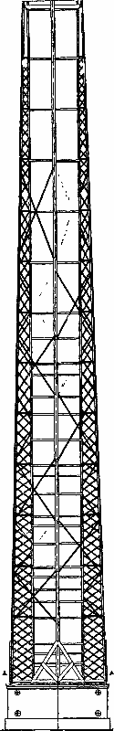
FIG. 1—ELEVATION.
FIG. 1—ELEVATION.
At a recent meeting of the Industrial Society of Amiens, Mr. Schmidt, engineer of the Steam Users' Association, read a paper in which he described the process employed in the construction of a large chimney of peculiar character for the Rocourt distillery, at St. Quentin.
At a recent meeting of the Industrial Society of Amiens, Mr. Schmidt, an engineer from the Steam Users' Association, presented a paper describing the process used to build a uniquely designed chimney for the Rocourt distillery in St. Quentin.
This chimney, which is cylindrical in form, is 140 feet in height, and has an internal diameter of 8½ feet from base to summit. The coal consumed for the nine generators varies between 860 and 1,200 pounds per hour and per 10 square feet of section.
This chimney, which is cylindrical in shape, stands 140 feet tall and has an internal diameter of 8½ feet from bottom to top. The coal used for the nine generators ranges from 860 to 1,200 pounds per hour for every 10 square feet of cross-section.
The ground that was to support this chimney consisted of very aquiferous, cracked beds of marl, disintegrated by infiltrations of water from the distillery, and alternating with strata of clay. It became necessary, therefore, to build as light a chimney as possible. The problem was solved as follows, by Mr. Guendt, who was then superintendent of the Rocourt establishment.
The ground meant to support this chimney was made up of very waterlogged, cracked marl beds, worn down by water from the distillery, and alternating with layers of clay. It was necessary, therefore, to construct the lightest chimney possible. Mr. Guendt, who was then the superintendent of the Rocourt facility, resolved the issue as follows.
Upon a wide concrete foundation a pedestal was built, in which were united the various smoke conduits, and upon this pedestal were erected four lattice girders, C, connected with each other by St. Andrew's crosses. The internal surface of these girders is vertical and the external is inclined. Within the framework there was built a five-inch thick masonry wall of bricks, made especially for the purpose. The masonry was then strengthened and its contact with the girders assured by numerous hoops, especially at the lower part; some of them internal, others external, to the surface of the girders, and others of angle irons, all in four parts.
On a wide concrete base, a pedestal was built that combined the various smoke pipes. On this pedestal, four lattice girders, C, were erected and connected to each other by St. Andrew's crosses. The inside surface of these girders is vertical, while the outside is angled. Inside the framework, a five-inch thick brick wall, specifically made for this purpose, was constructed. The masonry was reinforced, and its connection to the girders was secured with numerous hoops, particularly at the bottom; some were on the inside, others on the outside of the girders, and others were made of angle iron, all in four sections.
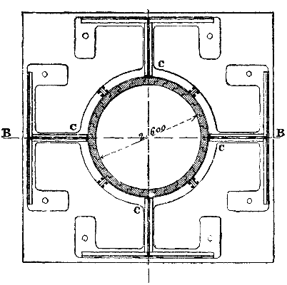
FIG. 2—HORIZONTAL SECTION.
FIG. 2—HORIZONTAL SECTION.
The anchors rest upon a cast iron foundation plate connected, through strong bolts embedded in the pedestal, with a second plate resting upon the concrete.
The anchors sit on a cast iron foundation plate, linked by sturdy bolts that are set into the pedestal, to a second plate that sits on the concrete.
As the metallic framework was calculated for resisting the wind, the brick lining does not rest against it permanently above. The weight of the chimney is 1,112,200 pounds, and the foundation is about 515 square feet in area; and, consequently, the pressure upon the ground is about 900 pounds to the square inch. The cost was $3,840.
As the metal structure was designed to withstand the wind, the brick lining doesn’t sit against it permanently at the top. The chimney weighs 1,112,200 pounds, and the foundation covers about 515 square feet; therefore, the pressure on the ground is around 900 pounds per square inch. The cost was $3,840.
The chimney was built six years ago, and has withstood the most violent hurricanes.
The chimney was built six years ago and has weathered the most intense hurricanes.
The mounting of the iron framework was effected by means of a motor and two men, and took a month. The brick lining was built up in eight days by a mason and his assistant.
The iron framework was put together using a motor and two men, and it took a month. The brick lining was completed in eight days by a mason and his assistant.
A chimney of the same size, all of brick, erected on the same foundation, would have weighed 2,459,600 pounds (say a load of 3,070 pounds to the square inch), and would have cost about $2,860.
A brick chimney of the same size, built on the same foundation, would have weighed 2,459,600 pounds (about a load of 3,070 pounds per square inch) and would have cost around $2,860.
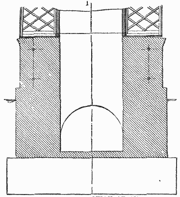
FIG. 3—VERTICAL SECTION OF THE CHIMNEY.
FIG. 3—VERTICAL SECTION OF THE CHIMNEY.
The chimney of the Rocourt distillery is, therefore, lighter by half, and cost about a third more, than one of brick; but, at the present price of metal, the difference would be slight.—Annales Industrielles.
The chimney of the Rocourt distillery is now half the weight and about a third more expensive than a brick one; however, considering the current metal prices, the difference would be minimal.—Annales Industrielles.
THE PRODUCTION OF OXYGEN BY BRIN'S PROCESS.
Considerable interest has been aroused lately in scientific and industrial circles by a report that separation of the oxygen and nitrogen of the air was being effected on a large scale in London by a process which promises to render the gases available for general application in the arts. The cheap manufacture of the compounds of nitrogen from the gas itself is still a dream of chemical enthusiasts; and though the pure gas is now available, the methods of making its compounds have yet to be devised. But the industrial processes which already depend directly or indirectly on the chemical union of bodies with atmospheric oxygen are innumerable.
Recently, there's been a lot of interest in scientific and industrial circles due to a report that the separation of oxygen and nitrogen from the air is being done on a large scale in London using a process that could make those gases widely usable in various industries. The affordable production of nitrogen compounds from this gas is still just a dream for chemical enthusiasts; although pure nitrogen gas is now accessible, effective methods to create its compounds haven’t been developed yet. However, there are countless industrial processes that already rely directly or indirectly on the chemical combination of substances with atmospheric oxygen.
In all these processes the action of the gas is impeded by the bulky presence of its fellow constituent of air, nitrogen. We may say, for instance, in homely phrase, that whenever a fire burns there are four volumes of nitrogen tending to extinguish it for every volume of oxygen supporting its combustion, and to the same degree the nitrogen interferes with all other processes of atmospheric oxidation, of which most metallurgical operations may be given as instances. If, then, it has become possible to remove this diluent gas simply and cheaply in order to give the oxygen free play in its various applications, we are doubtless on the eve of a revolution among some of the most extensive and familiar of the world's industries.
In all these processes, the action of the gas is hindered by the heavy presence of nitrogen, which is another component of air. For example, we might say in simple terms that whenever a fire burns, there are four volumes of nitrogen trying to put it out for every volume of oxygen that fuels it, and in the same way, nitrogen interferes with all other atmospheric oxidation processes, many of which are involved in metallurgy. If it has now become possible to easily and cheaply remove this diluting gas to allow oxygen to be used freely in its various applications, we are certainly on the brink of a major change in some of the largest and most common industries in the world.
A series of chemical reactions has long been known by means of which oxygen could be separated out of air in the laboratory, and at various times processes based on these reactions have been patented for the production of oxygen on a large scale. Until recently, however, none of these methods gave sufficiently satisfactory results. The simplest and perhaps the best of them was based on the fact first noticed by Boussingault, that when baryta (BaO) is heated to low redness in a current of air, it takes up oxygen and becomes barium dioxide (BaO2), and that this dioxide at a higher temperature is reconverted into free oxygen and baryta, the latter being ready for use again. For many years it was assumed, however, by chemists that this ideally simple reaction was inapplicable on a commercial scale, owing to the gradual loss of power to absorb oxygen which was always found to take place in the baryta after a certain number of operations. About eight years ago Messrs. A. & L. Brin, who had studied chemistry under Boussingault, undertook experiments with the view of determining why the baryta lost its power of absorbing oxygen.
A series of chemical reactions has been known for a long time that allows oxygen to be separated from air in the lab, and various processes based on these reactions have been patented for producing oxygen on a large scale. Until recently, however, none of these methods provided sufficiently satisfactory results. The simplest and possibly the best of them was based on the observation first made by Boussingault, that when baryta (BaO) is heated to a low red glow in an air current, it absorbs oxygen and turns into barium dioxide (BaO2). This dioxide can then be converted back into free oxygen and baryta at a higher temperature, allowing the baryta to be reused. For many years, chemists believed that this ideally simple reaction couldn't be applied commercially due to the gradual loss of the ability to absorb oxygen that baryta experienced after a certain number of uses. About eight years ago, Messrs. A. & L. Brin, who studied chemistry under Boussingault, began experiments to determine why baryta lost its ability to absorb oxygen.
They found that it was owing to molecular and physical changes caused in it by impurities in the air used and by the high temperature employed for decomposing the dioxide. They discovered that by heating the dioxide in a partial vacuum the temperature necessary to drive off its oxygen was much reduced. They also found that by supplying the air to the baryta under a moderate pressure, its absorption of oxygen was greatly assisted. Under these conditions, and by carefully purifying the air before use, they found that it became possible to use the baryta an indefinite number of times. Thus the process became practically, as it was theoretically, continuous.
They found that it was due to molecular and physical changes caused by impurities in the air used and the high temperature needed to break down the dioxide. They discovered that by heating the dioxide in a partial vacuum, the temperature required to release its oxygen was significantly lowered. They also found that by supplying air to the baryta under moderate pressure, its oxygen absorption was greatly improved. Under these conditions, and by carefully cleaning the air before using it, they found that it became possible to use the baryta an endless number of times. Thus, the process became practically, as it was theoretically, continuous.
After securing patent protection for their process, Messrs. Brin erected a small producer in Paris, and successfully worked it for nearly three years without finding a renewal of the original charge of baryta once necessary. This producer was exhibited at the Inventions Exhibition in London, in 1885. Subsequently an English company was formed, and in the autumn of last year Brin's Oxygen Company began operations in Horseferry Road, Westminster, where a large and complete demonstration plant was erected, and the work commenced of developing the production and application of oxygen in the industrial world.
After securing patent protection for their process, Messrs. Brin set up a small production facility in Paris and successfully operated it for almost three years without needing to renew the original baryta charge. This production facility was showcased at the Inventions Exhibition in London in 1885. Later, an English company was formed, and in the fall of last year, Brin's Oxygen Company started operations on Horseferry Road in Westminster, where a large and fully equipped demonstration plant was built, and work began on developing the production and application of oxygen in the industrial sector.

APPARATUS FOR MAKING OXYGEN.
OXYGEN GENERATOR.
We give herewith details of the plant now working at Westminster. It is exceedingly simple. On the left of the side elevation and plan are shown the retorts, on the right is an arrangement of pumps for alternately supplying air under pressure and exhausting the oxygen from the retorts. As is shown in the plan, two sets of apparatus are worked side by side at Westminster, the seventy-two retorts shown in the drawings being divided into two systems of thirty-six. Each system is fed by the two pumps on the corresponding side of the boiler. Each set of retorts consists of six rows of six retorts each, one row above the other. They are heated by a small Wilson's producer, so that the attendant can easily regulate the supply of heat and obtain complete control over the temperature of the retorts. The retorts, A, are made of wrought iron and are about 10 ft long and 8 in. diameter. Experience, however, goes to prove that there is a limit to the diameter of the retorts beyond which the results become less satisfactory. This limit is probably somewhat under 8 in. Each retort is closely packed with baryta in lumps about the size of a walnut. The baryta is a heavy grayish porous substance prepared by carefully igniting the nitrate of barium; and of this each retort having the above dimensions holds about 125 lb. The retorts so charged are closed at each end by a gun metal lid riveted on so as to be air tight. From the center of each lid a bent gun metal pipe, B, connects each retort with the next of its series, so that air introduced into the end retort of any row may pass through the whole series of six retorts. Suppose now that the operations are to commence.
We are providing details about the plant currently operating at Westminster. It's very straightforward. On the left side of the elevation and plan, you'll see the retorts, and on the right, there's a setup of pumps that alternately supply pressurized air and remove oxygen from the retorts. As shown in the plan, two sets of equipment are working side by side at Westminster, with the seventy-two retorts illustrated in the drawings split into two systems of thirty-six each. Each system is fed by the two pumps located on the corresponding side of the boiler. Each set of retorts has six rows, with six retorts in each row, stacked one above the other. They are heated by a small Wilson's producer, allowing the operator to easily regulate the heat supply and maintain complete control over the temperature of the retorts. The retorts, labeled A, are made of wrought iron and measure about 10 feet long and 8 inches in diameter. Experience shows that there's a limit to how large the diameter of the retorts can be before the results become less effective. That limit is likely just under 8 inches. Each retort is tightly packed with baryta chunks about the size of a walnut. Baryta is a heavy, grayish, porous material created by carefully igniting barium nitrate; each retort of the specified dimensions holds about 125 pounds of it. Once loaded, the retorts are sealed at each end with a gunmetal lid that is riveted on to ensure it's airtight. From the center of each lid, a bent gunmetal pipe, labeled B, connects each retort to the next in the series, so that air introduced into the end retort of any row can flow through all six retorts in the series. Now, let's assume that the operations are about to begin.
The retorts are first heated to a temperature of about 600° C. or faint redness, then the air pumps, C C, are started. Air is drawn by them through the purifier, D, where it is freed from carbon dioxide and moisture by the layers of quicklime and caustic soda with which the purifier is charged. The air is then forced along the pipe, E, into the small air vessel, F, which acts as a sort of cushion to prevent the baryta in the retorts being disturbed by the pulsation of the pumps. From this vessel the air passes by the pipe, G, and is distributed in the retorts as rapidly as possible at such a pressure that the nitrogen which passes out unabsorbed at the outlet registers about 15 lb. to the square inch. With the baryta so disposed in the retorts as to present as large a superficies as possible to the action of the air, it is found that in 1½ to 2 hours—during which time about 12,000 cub. ft of air have been passed through the retorts—the gas at the outlet fails to extinguish a glowing chip, indicating that oxygen is no longer being absorbed. The pumping now ceases, and the temperature of the retorts is raised to about 800° C. The workman is able to judge the temperature with sufficient accuracy by means of the small inspection holes, H, fitted with panes of mica, through which the color of the heat in the furnace can be distinguished. The pumps are now reversed and the process of exhaustion begins. At Westminster the pressure in the retorts is reduced to about 1½ in. of mercury. In this partial vacuum the oxygen is given off rapidly, and if forced by the pumps through another pipe and away into an ordinary gas holder, where it is stored for use. With powerful pumps such as are used in the plant under notice the whole of the oxygen can be drawn off in an hour, and from one charge a yield of about 2,000 cub. ft. is obtained. With a less perfect vacuum the time is longer—even as much as four hours. The whole operation of charging and exhausting the retorts can be completed in from three to four hours. As soon as the evolution of oxygen is finished, the doors, K, and ventilators, L, may be opened and the retorts cooled for recharging.
The retorts are first heated to around 600° C or a faint red color, then the air pumps, C C, are turned on. They draw air through the purifier, D, which removes carbon dioxide and moisture using quicklime and caustic soda. The air is then pushed through the pipe, E, into the small air vessel, F, which acts as a cushion to prevent the baryta in the retorts from getting disturbed by the pump's pulsations. From this vessel, the air goes through the pipe, G, and is distributed in the retorts quickly at a pressure that allows nitrogen to exit unabsorbed at around 15 lb. per square inch. With the baryta arranged in the retorts to maximize its surface area for the air’s action, it’s found that in 1½ to 2 hours—during which about 12,000 cubic feet of air have passed through the retorts—the gas at the outlet can no longer extinguish a glowing chip, indicating that no more oxygen is being absorbed. The pumping stops, and the temperature of the retorts is raised to about 800° C. The worker can accurately judge the temperature through small inspection holes, H, fitted with mica panes that show the furnace's heat color. The pumps are then reversed, and the exhaust process begins. At Westminster, the pressure in the retorts drops to about 1½ inches of mercury. In this partial vacuum, oxygen is released quickly and can be pushed by the pumps through another pipe into an ordinary gas holder for storage. With powerful pumps used in this facility, all the oxygen can be collected in an hour, yielding about 2,000 cubic feet from one charge. With a less effective vacuum, it may take up to four hours. The entire process of charging and exhausting the retorts can be finished in three to four hours. As soon as the oxygen release is complete, the doors, K, and ventilators, L, can be opened to cool the retorts for recharging.
The cost of producing oxygen at Westminster, under specially expensive conditions, is high—about 12s. per 1,000 cub. ft. When we consider, however, that the cost should only embrace attendance, fuel, wear and tear, and a little lime and soda for the purifiers, that the consumption of fuel is small, the wear and tear light, and that the raw material—air—is obtained for nothing, it ought to be possible to produce the gas for a third or fourth of this amount in most of our great manufacturing centers, where the price of fuel is but a third of that demanded in London, and where provision could be made for economizing the waste heat, which is entirely lost in the Westminster installation. Moreover, in estimating this cost all the charges are thrown on the oxygen; were there any means of utilizing the 4,000 cub. ft. of nitrogen at present blown away as waste for every thousand cubic feet of oxygen produced, the nitrogen would of course bear its share of the cost.
The cost of producing oxygen at Westminster, under especially expensive conditions, is high—about 12 shillings per 1,000 cubic feet. However, if we consider that this cost should only include attendance, fuel, wear and tear, and a little lime and soda for the purifiers, and that fuel consumption is low, wear and tear is minimal, and the raw material—air—is free, it should be possible to produce the gas for a third or fourth of this amount in most of our major manufacturing centers. There, the price of fuel is only about a third of what it costs in London, and they could also find ways to recycle the waste heat that is completely lost in the Westminster setup. Additionally, in calculating this cost, all expenses are charged to the oxygen; if there were a way to use the 4,000 cubic feet of nitrogen that is currently wasted for every 1,000 cubic feet of oxygen produced, the nitrogen would, of course, contribute to the overall cost.
The question of the application of the oxygen is one which must be determined in its manifold bearings mainly by the experiments of chemists and scientific men engaged in industrial work. Having ascertained the method by which and the limit of cost within which it is possible to use oxygen in their work, it can be seen whether by Brin's process the gas can be obtained within that limit.
The issue of using oxygen needs to be addressed in its various aspects, primarily through experiments conducted by chemists and scientists involved in industrial work. Once they determine the method and cost limit for using oxygen in their operations, it will be possible to see if Brin's process can provide the gas within that budget.
Mr. S.R. Ogden, the manager of the corporation gasworks at Blackburn, has already made interesting experiments on the application of oxygen in the manufacture of illuminating gas. In order to purify coal gas from compounds of sulphur, it is passed through purifiers charged with layers of oxide of iron. When the oxide of iron has absorbed as much sulphur as it can combine with, it is described as "foul." It is then discharged and spread out in the open air, when, under the influence of the atmospheric oxygen, it is rapidly decomposed, the sulphur is separated out in the free state, and oxide of iron is reformed ready for use again in the purifiers. This process is called revivification, and it is repeated until the accumulation of sulphur in the oxide is so great (45 to 55 per cent.) that it can be profitably sold to the vitriol maker. Hawkins discovered that by introducing about 3 per cent. of air into the gas before passing it through the purifiers, the oxygen of the air introduced set free the sulphur from the iron as fast as it was absorbed. Thus the process of revivification could be carried on in the purifiers themselves simultaneously with the absorption of the sulphur impurities in the gas.
Mr. S.R. Ogden, the manager of the gasworks corporation in Blackburn, has already conducted intriguing experiments on using oxygen to produce illuminating gas. To remove sulfur compounds from coal gas, it passes through purifiers filled with layers of iron oxide. When the iron oxide has absorbed all the sulfur it can handle, it's called "foul." It's then removed and spread out in the open air, where, influenced by atmospheric oxygen, it quickly decomposes, freeing the sulfur and reforming the iron oxide for reuse in the purifiers. This process, known as revivification, is repeated until the sulfur accumulation in the oxide reaches a point (45 to 55 percent) where it can be sold profitably to vitriol manufacturers. Hawkins found that by adding about 3 percent of air into the gas before it goes through the purifiers, the oxygen from the air releases sulfur from the iron as quickly as it gets absorbed. Therefore, the process of revivification can occur in the purifiers at the same time as sulfur impurities are absorbed from the gas.
A great saving of labor was thus effected, and also an economy in the use of the iron oxide, which in this way could be left in the purifiers until charged with 75 per cent. of sulphur. Unfortunately it was found that this introduction of air for the sake of its oxygen meant also the introduction of much useless nitrogen, which materially reduced the illuminating power of the gas. To restore this illuminating power the gas had to be recarbureted, and this again meant cost in labor and material. Now, Mr. Ogden has found by a series of conclusive experiments made during a period of seventy-eight days upon a quantity of about 4,000,000 cub. ft. of gas, that by introducing 1 per cent. of oxygen into the gas instead of 3 per cent. of air, not only is the revivification in situ effected more satisfactorily than with air, but at the same time the illuminating power of the gas, so far from being decreased, is actually increased by one candle unit.
A significant reduction in labor was achieved, along with a cost-saving measure in the use of iron oxide, which could now remain in the purifiers until it absorbed 75 percent of sulfur. Unfortunately, the addition of air for its oxygen also brought in a lot of unnecessary nitrogen, which significantly lowered the gas's illuminating power. To restore this illuminating power, the gas had to be re-carbureted, leading to additional costs in labor and materials. Mr. Ogden has conducted a series of conclusive experiments over seventy-eight days on about 4,000,000 cubic feet of gas. He found that by introducing 1 percent of oxygen into the gas instead of 3 percent of air, not only is the revitalization in situ more effective than with air, but the gas's illuminating power is actually increased by one candle unit instead of being decreased.

SIDE ELEVATION OF APPARATUS

GENERAL PLAN OF APPARATUS
THE PRODUCTION OF OXYGEN BY BRIN'S PROCESS.
Side view of the device
DEVICE'S OVERALL DESIGN
THE GENERATION OF OXYGEN USING BRIN'S METHOD.
So satisfied is he with his results that he has recommended the corporation to erect a plant for the production of oxygen at the Blackburn gas works, by which he estimates that the saving to the town on the year's make of gas will be something like £2,500. The practical observations of Mr. Ogden are being followed up by a series of exhaustive experiments by Mr. Valon, A.M. Inst. C.E., also a gas engineer. The make of an entire works at Westgate is being treated by him with oxygen. Mr. Valon has not yet published his report, as the experiments are not quite complete; but we understand that his results are even more satisfactory than those obtained at Blackburn.
He is so pleased with his results that he has suggested the company build a plant to produce oxygen at the Blackburn gas works, which he believes will save the town about £2,500 on the annual gas production. Mr. Ogden's practical findings are being followed up with a series of thorough experiments by Mr. Valon, A.M. Inst. C.E., who is also a gas engineer. He is treating the production of an entire plant at Westgate with oxygen. Mr. Valon hasn't published his report yet since the experiments aren't completely finished, but we understand that his findings are even more promising than those from Blackburn.
In conclusion we may indicate a few other of the numerous possible applications of cheap oxygen which might be realized in the near future. The greatest illuminating effect from a given bulk of gas is obtained by mixing it with the requisite proportion of oxygen, and holding in the flame of the burning mixture a piece of some solid infusible and non-volatile substance, such as lime. This becomes heated to whiteness, and emits an intense light know as the Drummond light, used already for special purposes of illumination. By supplying oxygen in pipes laid by the side of the ordinary gas mains, it would be possible to fix small Drummond lights in place of the gas burners now used in houses; this would greatly reduce the consumption of gas and increase the light obtained, or even render possible the employment of cheap non-illuminating combustible gases other than coal gas for the purpose.
In conclusion, we can point out a few other possible uses for inexpensive oxygen that could be realized soon. The most effective illumination from a given amount of gas is achieved by mixing it with the right amount of oxygen and holding a piece of a solid, infusible, and non-volatile material, like lime, in the flame of the burning mixture. This piece gets heated to a bright white and emits a strong light known as the Drummond light, which is already used for specific lighting purposes. By supplying oxygen through pipes installed alongside regular gas mains, we could replace traditional gas burners in homes with small Drummond lights. This would significantly reduce gas consumption and enhance the light output, or even allow for the use of inexpensive, non-illuminating combustible gases other than coal gas for this purpose.
Two obstacles at present lie in the way of this consummation—the cost of the oxygen and the want of a convenient and completely refractory material to take the place of the lime. Messrs. Brin believe they have overcome the first obstacle, and are addressing themselves, we believe, to the removal of the second. Again, the intense heat which the combustion of carbon in cheap oxygen will place at the disposal of the metallurgist cannot fail to play an important part in his operations. There are many processes, too, of metal refining which ought to be facilitated by the use of the gas. Then the production of pure metallic oxides for the manufacture of paints, the bleaching of oils and fats, the reduction of refractory ores of the precious metals on a large scale, the conversion of iron into steel, and numberless other processes familiar to the specialists whose walk is in the byways of applied chemistry, should all profit by the employment of this energetic agent. Doubtless, too, the investigation into methods of producing the compounds of nitrogen so indispensable as plant foods, and for which we are now dependent on the supplies of the mineral world, may be stimulated by the fact that there is available by Brin's process a cheap and inexhaustible supply of pure nitrogen.—Industries.
Two current obstacles stand in the way of this achievement—the cost of oxygen and the lack of a convenient, completely resistant material to replace lime. The Brin team believes they’ve tackled the first issue and is, we think, working on the second. Additionally, the intense heat generated by burning carbon in inexpensive oxygen will undoubtedly play a significant role in a metallurgist's work. Many metal refining processes should also be easier with this gas. Plus, the production of pure metallic oxides for making paints, bleaching oils and fats, large-scale reduction of tough ores containing precious metals, converting iron into steel, and countless other methods known to specialists in applied chemistry should all benefit from using this potent agent. It’s likely that research into producing nitrogen compounds, which are essential as plant fertilizers and currently reliant on mineral resources, may be encouraged by the availability of a cheap and endless supply of pure nitrogen through Brin's process.—Industries.
FRENCH DISINFECTING APPARATUS.

IMPROVED DISINFECTING APPARATUS.
Enhanced Disinfecting Device.
We represent herewith a sanitary train that was very successfully used during the prevalence of an epidemic of sudor Anglicus in Poitou this year. It consisted of a movable stove and a boiler. In reality, to save time, such agricultural locomotives as could be found were utilized; but hereafter, apparatus like those shown in the engraving, and which are specially constructed to accompany the stoves, will be employed. We shall quote from a communication made by Prof. Brouardel to the Academy of Medicine on this subject, at its session of September 13:
We present here a mobile sanitary unit that was very effectively used during the outbreak of sudor Anglicus in Poitou this year. It included a portable stove and a boiler. To save time, available agricultural vehicles were used; however, in the future, equipment like what is illustrated in the engraving, specifically designed to accompany the stoves, will be utilized. We will quote from a communication made by Prof. Brouardel to the Academy of Medicine on this topic during its meeting on September 13:
In the country we can never think of disinfecting houses with sulphurous acid, as the peasants often have but a single room, in which the beds of the entire family are congregated. Every one knows that the agglomerations that compose the same department are often distant from each other and the chief town by from two to three miles or more. This is usually the case in the departments of Vienne, Haute Vienne, Indre, etc. To find a disinfecting place in the chief town of the department is still difficult, and to find one in each of the hamlets is absolutely impossible. Families in which there are invalids are obliged to carry clothing and bedding to the chief town to be disinfected, and to go after them after the expiration of twenty-four hours. This is not an easy thing to do.
In the countryside, we can never think about disinfecting houses with sulfuric acid, since many families often have just one room where all the beds are crammed together. Everyone knows that the clusters of homes in the same area are often separated from the main town by two to three miles or more. This is typically true in the areas of Vienne, Haute Vienne, Indre, and so on. Finding a place to disinfect in the main town is still challenging, and locating one in each of the small villages is completely impossible. Families with sick members have to haul clothing and bedding to the main town for disinfection, then return to pick them up after twenty-four hours. This is not an easy task to manage.
It is easy to understand what difficulties must be met with in many cases, and so one has to be content to prescribe merely washing, and bleaching with lime—something that is simple and everywhere accepted, but insufficient. So, then, disinfection with sulphurous acid, which is easy in large cities, as was taught by the cholera epidemics of last year, is often difficult in the country. The objection has always be made to it, too, that it is of doubtful efficacy. It is not for us to examine this question here, but there is no doubt that damp steam alone, under pressure, effects a perfect disinfection, and that if this mode of disinfection could be applied in the rural districts (as it can be easily done in cities), the public health would be better protected in case of an epidemic.
It’s easy to see the challenges that often arise, so sometimes you can only recommend simple methods like washing and bleaching with lime—things that are straightforward and widely accepted but not enough. Disinfecting with sulfurous acid is typically easy in big cities, as we learned during last year's cholera outbreaks, but it can be challenging in rural areas. There’s always been some skepticism about its effectiveness. We don’t need to delve into that issue here, but it’s clear that moist steam under pressure provides excellent disinfection. If this method could be used in rural areas (as it can easily be in cities), public health would be much better safeguarded during an epidemic.
In cities one or more stationary steam stoves can always be arranged; but in the country movable ones are necessary. From instructions given by Prof. Brouardel, Messrs. Geneste & Herscher have solved the problem of constructing such stoves in a few days, and four have been put at the disposal of the mission.
In cities, one or more fixed steam stoves can always be set up; however, in the countryside, portable ones are needed. Based on guidance from Prof. Brouardel, Messrs. Geneste & Herscher have figured out how to build these stoves in just a few days, and four have been made available to the mission.
Dr. Thoinot, who directed this mission, in order to make an experiment with these apparatus, selected two points in which cases of sudor were still numerous, and in which the conditions were entirely different, and permitted of studying the working of the service and apparatus under various phases. One of these points was Dorat, chief town of Haute Vienne, a locality with a crowded population and presenting every desirable resource; and the other was the commune of Mauvieres, in Indre, where the population was scattered through several hamlets.
Dr. Thoinot, who led this mission, chose two locations to conduct experiments with this equipment where cases of sudor were still prevalent and where the conditions were completely different. This setup allowed for studying how the service and equipment functioned under various situations. One of these locations was Dorat, the main town of Haute Vienne, which had a dense population and offered all the necessary resources. The other was the commune of Mauvieres in Indre, where the population was spread out across several small villages.
The first stove was operated at Dorat, on the 29th of June, and the second at Mauvieres, on the 1st of July. A gendarme accompanied the stove in all its movements and remained with it during the disinfecting experiments. The Dorat stove was operated on the 29th of June and the 1st, 2d, and 3d of July. On the 30th of June it proceeded to disinfect the commune of Darnac. The Mauvieres stove, in the first place, disinfected the chief town of this commune on the 1st of July, and on the next day it was taken to Poulets, a small hamlet, and a dependent of the commune of Mauvieres. All the linen and all the clothing of the sick of this locality, which had been the seat of sudor, especially infantile, was disinfected. On the 4th of July, the stove went to Concremiers, a commune about three miles distant, and there finished up the disinfection that until then had been performed in the ordinary way.
The first stove was used in Dorat on June 29th, and the second one in Mauvieres on July 1st. A gendarme accompanied the stove during all its movements and stayed with it throughout the disinfection experiments. The Dorat stove was in operation on June 29th, as well as July 1st, 2nd, and 3rd. On June 30th, it disinfected the commune of Darnac. The Mauvieres stove first disinfected the main town of this commune on July 1st, and the following day, it was taken to Poulets, a small hamlet part of the commune of Mauvieres. All the linen and clothing of the local sick, particularly children with sudor, was disinfected. On July 4th, the stove went to Concremiers, a commune about three miles away, and completed the disinfection that had been done up to that point in the usual way.
The epidemic was almost everywhere on the wane at this epoch; but we judge that the test of the stoves was sufficient.
The epidemic was mostly fading away at this time; however, we believe that testing the stoves was adequate.
We are able to advance the following statement boldly: For the application of disinfection in the rural districts, the movable stove is the most practical thing that we know of. It is easily used, can be taken to the smallest hamlets, and can be transported over the roughest roads. It inspires peasants with no distrust. The first repugnance is easily overcome, and every one, upon seeing that objects come from the stove unharmed, soon hastens to bring to it all the contaminated linen, etc., that he has in the house.
We can confidently say this: For disinfecting in rural areas, the portable stove is the most practical option we know of. It’s easy to use, can be taken to the tiniest villages, and can be transported over the roughest roads. It doesn’t create any distrust among the peasants. The initial hesitation is easily overcome, and once they see that items come out of the stove unharmed, everyone quickly brings all the contaminated laundry and other items from their homes.
Further, we may add that the disinfection is accomplished in a quarter of an hour, and that it therefore keeps the peasant but a very short time from his work—an advantage that is greatly appreciated. Finally, a day well employed suffices to disinfect a small settlement completely. Upon the whole, disinfection by the stove under consideration is the only method that can always and everywhere be carried out.
Further, we can add that the disinfection is done in fifteen minutes, so it keeps the peasant away from his work for only a short time—an advantage that is highly valued. Finally, a single day is enough to completely disinfect a small settlement. Overall, disinfection using the stove in question is the only method that can be done consistently and everywhere.
We believe that it is called upon to render the greatest services in the future.
We believe that it is destined to provide the greatest services in the future.
The movable stove, regarding which Prof. Brouardel expresses himself in the above terms, consists of a cylindrical chamber, 3½ feet in internal diameter and 5 feet in length, closed in front by a hermetically jointed door. This cylinder, which constitutes the disinfection chamber, is mounted upon wheels and is provided with shafts, so that it can easily be hauled by a horse or mule. The cylinder is of riveted iron plate, and is covered with a wooden jacket. The door is provided with a flange that enters a rubber lined groove in the cylinder, and to it are riveted wrought iron forks that receive the nuts of hinged bolts fixed upon the cylinder. The nuts are screwed up tight, and the flange of the door, compressing the rubber lining, renders the joint hermetical. The door, which is hinged, is provided with a handle, which, when the stove is closed, slides over an inclined plane fixed to the cylinder.
The movable stove, which Prof. Brouardel describes in the above terms, consists of a cylindrical chamber that is 3½ feet in internal diameter and 5 feet in length, sealed at the front by a hermetically sealed door. This cylinder, serving as the disinfection chamber, is mounted on wheels and includes shafts for easy towing by a horse or mule. The cylinder is made of riveted iron plate and is covered with a wooden jacket. The door features a flange that fits into a rubber-lined groove in the cylinder, and it has riveted wrought iron forks that hold the nuts of hinged bolts attached to the cylinder. The nuts are tightened securely, and the flange of the door compresses the rubber lining, making the joint airtight. The door, which is hinged, has a handle that, when the stove is closed, slides over an inclined plane attached to the cylinder.
The steam enters a cast iron box in the stove through a rubber tube provided with a threaded coupling. The entrance of the steam is regulated by a cock. The box is provided with a safety and pressure gauge and a small pinge cock. In the interior of the stove the entrance of the steam is masked by a large tinned copper screen, which is situated at the upper part and preserves the objects under treatment from drops of water of condensation. These latter fall here and there from the screen, follow the sides of the cylinder, and collect at the bottom, from whence they are drawn off through a cock placed in the rear.
The steam enters a cast iron box in the stove through a rubber tube with a threaded connector. The steam flow is controlled by a valve. The box is equipped with a safety and pressure gauge, as well as a small drain valve. Inside the stove, the steam entrance is covered by a large tinned copper screen, located at the top, which protects the items being treated from water condensation drops. These drops fall here and there from the screen, run down the sides of the cylinder, and gather at the bottom, where they are removed through a valve located at the back.
The sides are lined internally with wood, which prevents the objects to be infected from coming into contact with the metal. The objects to be treated are placed upon wire cloth shelves. The pinge cock likewise serves for drawing off the air or steam contained in the apparatus.
The sides are lined on the inside with wood, which keeps the items from getting contaminated by the metal. The items being treated are placed on wire mesh shelves. The drain valve also works to remove the air or steam inside the device.
The stove is supported upon an axle through the intermedium of two angle irons riveted longitudinally upon the cylinder. The axle is cranked, and its wheels, which are of wood, are 4½ feet in diameter. The shafts are fixed to the angle irons. The apparatus is, in addition, provided with a seat, a brake, and prop rods before and behind to keep it horizontal when in operation.
The stove is mounted on an axle using two angle irons that are riveted along the cylinder. The axle is bent, and its wheels, made of wood, are 4½ feet in diameter. The shafts are attached to the angle irons. Additionally, the setup includes a seat, a brake, and support rods in the front and back to keep it level while in use.
The boiler that supplies this stove is vertical and is mounted upon four wheels. It is jacketed with wood, and is provided with a water level, two gauge cocks, a pressure gauge, two spring safety valves, a steam cock provided with a rubber tube that connects with that of the stove, an ash pan, and a smoke stack. In the rear there are two cylindrical water reservoirs that communicate with each other, and are designed to feed the boiler through an injector. Beneath these reservoirs there is a fuel box. In front there is a seat whose box serves to hold tools and various other objects.—La Nature.
The boiler that powers this stove is vertical and sits on four wheels. It's wrapped in wood and has a water level, two gauge cocks, a pressure gauge, two spring safety valves, and a steam cock connected to a rubber tube that links it to the stove. There's also an ash pan and a smoke stack. At the back, there are two cylindrical water tanks that connect with each other and are meant to supply the boiler through an injector. Below these tanks is a fuel box. In front, there's a seat with a compartment that holds tools and various other items.—La Nature.
AN ELECTRICAL GOVERNOR.
We abstract the following from a paper on electric lighting by Prof. J.A. Fleeming, read before the Iron and Steel Institute, Manchester. The illustration is from Engineering.
We take the following from a paper on electric lighting by Prof. J.A. Fleeming, presented to the Iron and Steel Institute in Manchester. The illustration is from Engineering.
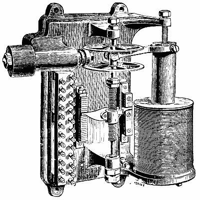
ELECTRICAL GOVERNOR.
ELECTRICAL GOVERNOR.
One of the questions which most frequently occurs in reference to mill and factory lighting is whether the factory engines can be used to run the dynamo. As a broad, general rule, there can be no question that the best results are obtained by using a separate dynamo engine, controlled by a good governor, set apart for that purpose. With an ordinary shunt dynamo, the speed ought not to vary more than 2 or 3 per cent. of its normal value on either side of that value. Hence, if a dynamo has a normal speed of 1,000, it should certainly not vary over a greater range than from 970 to 980 to 1,020 to 1,030. In many cases there may be shafting from which the necessary power can be taken, and of which the speed is variable only within these limits. There are several devices by which it has been found possible to enable a dynamo to maintain a constant electromotive force, even if the speed of rotation varies over considerable limits. One of these is that (see illustration) due to Messrs. Trotter & Ravenshaw, and applicable to shunt or series machines.
One of the most common questions about lighting in mills and factories is whether the factory engines can power the dynamo. Generally, it's clear that the best results come from using a separate dynamo engine that’s managed by a reliable governor specifically for that purpose. With a standard shunt dynamo, the speed shouldn't fluctuate more than 2 or 3 percent from its normal value. So, if a dynamo has a normal speed of 1,000, it definitely shouldn't deviate more than from 970 to 980 and from 1,020 to 1,030. In many situations, there may be shafting available that can provide the required power, with speed only changing within these limits. There are various devices that have been proven to help a dynamo maintain a constant electromotive force, even if the rotation speed varies significantly. One of these is the device (see illustration) created by Messrs. Trotter & Ravenshaw, which can be used for both shunt and series machines.
In the circuit of the field magnet is placed a variable resistance. This resistance is thrown in or out by means of a motor device actuated by an electromotive force indicator. A plunger of soft iron is suspended from a spring, and hangs within a solenoid of wire, which solenoid is in connection with the terminals of the dynamo. Any increase or diminution of the electromotive force causes this iron to move in or out of the core, and its movement is made to connect or disconnect the gearing which throws in the field magnet resistance with a shaft driven by the engine itself. The principle of the apparatus is therefore that small variations of electromotive force are made to vary inversely the strength of the magnetic field through the intervention of a relay mechanism in which the power required to effect the movement is tapped from the engine.
In the circuit of the field magnet, there’s a variable resistor. This resistor is switched on or off by a motor device that’s controlled by an electromotive force indicator. A plunger made of soft iron is suspended from a spring and hangs inside a wire solenoid, which is connected to the dynamo's terminals. Any increase or decrease in the electromotive force causes the iron to move in or out of the core, and this movement is used to connect or disconnect the gearing that regulates the field magnet resistance with a shaft driven by the engine. The principle of the apparatus is that small changes in electromotive force inversely affect the strength of the magnetic field through a relay mechanism, where the power needed for the movement is drawn from the engine.
With the aid of such a governor it is possible to drive a dynamo from a mill shaft providing the requisite power, but of which the speed of rotation is not sufficiently uniform to secure alone efficient regulation of electromotive force. Another device, patented by Mr. Crompton, is a modification of that method of field magnet winding commonly known as compound winding. The field magnets are wound over with two wires, one of which has a high resistance and is arranged as a shunt, and the other of which has a low resistance and is arranged in series. Instead, however, of the magnetizing powers of these coils being united in the same direction as an ordinary compound winding, they are opposed to one another. That is to say, the current in the shunt wire tends to magnetize the iron of the field magnets in an opposite direction to that of the series wire. It results from this that any slight increase of speed diminishes the strength of the magnetic field, and vice versa. Accordingly, within certain limits, the electromotive force of the dynamo is independent of the speed of rotation.
With the help of such a governor, it’s possible to run a dynamo from a mill shaft, supplying the necessary power, but the rotation speed isn’t consistent enough to effectively regulate the electromotive force on its own. Another device, patented by Mr. Crompton, is a variation of the field magnet winding method commonly known as compound winding. The field magnets are wound with two wires: one has a high resistance and is set up as a shunt, while the other has a low resistance and is set up in series. However, instead of the magnetizing effects of these coils working together in the same direction like in a typical compound winding, they work against each other. This means that the current in the shunt wire tends to magnetize the iron of the field magnets in the opposite direction to that of the series wire. As a result, any slight increase in speed reduces the strength of the magnetic field, and vice versa. Therefore, within certain limits, the electromotive force of the dynamo is unaffected by the rotation speed.
THE ELECTRIC CURRENT AS A MEANS OF INCREASING THE TRACTIVE ADHESION OF RAILWAY MOTORS AND OTHER ROLLING CONTACTS.1
By ELIAS E. RIES.
The object of this paper is to lay before you the results of some recent experiments in a comparatively new field of operation, but one that, judging from the results already attained, is destined to become of great importance and value in its practical application to various branches of industry.
The purpose of this paper is to present the findings of some recent experiments in a relatively new area of study that, based on the results we've already seen, is poised to become very important and valuable for practical use in various industries.
I say "comparatively new" because the underlying principles involved in the experiments referred to have, to a certain extent, been employed (in, however, a somewhat restricted sense) for purposes analogous to those that form the basis of this communication.
I say "comparatively new" because the basic principles behind the experiments mentioned have, to some degree, been used (though in a somewhat limited way) for purposes similar to those that are the foundation of this message.
As indicated by the title, the subject that will now occupy our attention is the use of the electric current as a means of increasing and varying the frictional adhesion of rolling contacts and other rubbing surfaces, and it is proposed to show how this effect may be produced, both by means of the direct action of the current itself and by its indirect action through the agency of electro-magnetism.
As the title suggests, we’ll now focus on how electric current can be used to enhance and modify the frictional adhesion of rolling contacts and other surfaces that rub against each other. We'll demonstrate how this effect can be achieved, both through the direct influence of the current itself and through its indirect impact via electromagnetism.
Probably the first instance in which the electric current was directly employed to vary the amount of friction between two rubbing surfaces was exemplified in Edison's electro-motograph, in which the variations in the strength of a telephonic current caused corresponding variations in friction between a revolving cylinder of moistened chalk and the free end of an adjustable contact arm whose opposite extremity was attached to the diaphragm of the receiving telephone. This device was extremely sensitive to the least changes in current strength, and if it were not for the complication introduced by the revolving cylinder, it is very likely that it would to-day be more generally used.
Probably the first time electric current was directly used to change the amount of friction between two surfaces was in Edison's electro-motograph. In this device, changes in the strength of a telephone current led to corresponding changes in friction between a rotating cylinder of moistened chalk and the free end of an adjustable contact arm, which was connected to the diaphragm of the receiving telephone. This device was highly sensitive to even the slightest changes in current strength, and if it weren't for the complexity introduced by the rotating cylinder, it would likely be more widely used today.
It has also been discovered more recently that in the operation of electric railways in which the track rails form part of the circuit, a considerable increase in the tractive adhesion of the driving wheels is manifested, due to the passage of the return current from the wheels into the track. In the Baltimore and Hampden electric railway, using the Daft "third rail" system, this increased tractive adhesion enables the motors to ascend without slipping a long grade of 350 feet to the mile, drawing two heavily loaded cars, which result, it is claimed, is not attainable by steam or other self-propelling motors of similar weight. In the two instances just cited the conditions are widely different, as regards the nature of the current employed, the mechanical properties of the surfaces in contact, and the electrical resistance and the working conditions of the respective circuits. In both, however, as clearly demonstrated by the experiments hereinafter referred to, the cause of the increased friction is substantially the same.
It has also been discovered more recently that in the operation of electric railways where the track rails are part of the circuit, there’s a significant increase in the tractive adhesion of the driving wheels due to the flow of return current from the wheels into the track. In the Baltimore and Hampden electric railway, which uses the Daft "third rail" system, this increased tractive adhesion allows the motors to climb a steep grade of 350 feet per mile without slipping while pulling two heavily loaded cars, a feat that is said to be unachievable by steam or other self-propelled motors of similar weight. In the two instances just mentioned, the conditions differ greatly in terms of the type of current used, the mechanical properties of the surfaces in contact, and the electrical resistance and working conditions of the respective circuits. However, in both cases, as clearly shown by the experiments referred to later, the reason for the increased friction is essentially the same.
In order to ascertain the practical value of the electric current as a means of increasing mechanical friction, and, if possible, render it commercially and practically useful wherever such additional friction might be desirable, as for example in the transmission of power, etc., a series of experiments were entered into by the author, which, though not yet fully completed, are sufficiently advanced to show that an electric current, when properly applied, is capable of very materially increasing the mechanical friction of rotating bodies, in some cases as much as from 50 to 100 per cent., with a very economical expenditure of current; this increase depending upon the nature of the substances in contact and being capable of being raised by an increased flow of current.
To determine the practical value of electric current in increasing mechanical friction and to potentially make it commercially and practically useful wherever that extra friction might be needed, like in power transmission, the author conducted a series of experiments. Although these experiments are not yet fully finished, they have progressed enough to demonstrate that when applied correctly, an electric current can significantly boost the mechanical friction of rotating bodies, sometimes increasing it by 50 to 100 percent, with a relatively low consumption of current. This increase depends on the types of materials in contact and can be enhanced by increasing the current flow.
Before entering into a description of the means by which this result is produced, and how it is proposed to apply this method practically to railway and other purposes, it may be well to give a general outline of what has so far been determined. These experiments have shown that the coefficient of friction between two conducting surfaces is very much increased by the passage therethrough of an electric current of low electromotive force and large volume, and this is especially noticeable between two rolling surfaces in peripheral contact with each other, or between a rolling and a stationary surface, as in the case of a driving wheel running upon a railway rail. This effect increases with the number of amperes of current flowing through the circuit, of which the two surfaces form part, and is not materially affected by the electromotive force, so long as the latter is sufficient to overcome the electrical resistance of the circuit. This increase in frictional adhesion is principally noticeable in iron, steel, and other metallic bodies, and is due to a molecular change in the conducting substances at their point of contact (which is also the point of greatest resistance in the circuit), caused by the heat developed at that point. This heat is ordinarily imperceptible, and becomes apparent only when the current strength is largely augmented. It is therefore probable that a portion of this increased tractive adhesion is due directly to the current itself aside from its heating effect, although I have not as yet been able to ascertain this definitely. The most economical and efficient results have been obtained by the employment of a transformed current of extremely low electromotive force (between ½ and 1 volt), but of very large volume or quantity, this latter being variable at will, so as to obtain different degrees of frictional resistance in the substances under observation.
Before describing how this result is achieved and how this method is meant to be practically applied to railways and other purposes, it’s useful to provide a general overview of what has been established so far. These experiments have shown that the coefficient of friction between two conductive surfaces greatly increases when an electric current of low electromotive force and large volume passes through them. This effect is particularly noticeable between two rolling surfaces in contact with each other, or between a rolling surface and a stationary one, such as a driving wheel on a railway rail. The friction increases with the number of amperes flowing in the circuit formed by the two surfaces and is not significantly impacted by the electromotive force, as long as it is enough to overcome the circuit's electrical resistance. This increase in frictional adhesion is especially significant in iron, steel, and other metals, and is caused by a molecular change in the conductive materials at their point of contact (which is also the point of highest resistance in the circuit), a change triggered by the heat generated at that point. This heat is usually imperceptible and only becomes noticeable when the current strength is significantly increased. Thus, it’s likely that some of this increased tractive adhesion results directly from the current itself, apart from its heating effect, although I have not yet been able to confirm this definitively. The most economical and effective results have been achieved using a transformed current with extremely low electromotive force (between ½ and 1 volt), but with a very large volume, which can be varied at will to achieve different levels of frictional resistance in the materials being examined.
These experiments were originally directed mainly toward an endeavor to increase the tractive adhesion of the driving wheels of locomotives and other vehicles, and to utilize the electric current for this purpose in such a manner as to render it entirely safe, practical, and economical. It will be apparent at once that a method of increasing the tractive power of the present steam locomotives by more than 50 per cent. without adding to their weight and without injury to the roadbed and wheel tires, such as is caused by the sand now commonly used, would prove of considerable value, and the same holds true with respect to electrically propelled street cars, especially as it has been found exceedingly difficult to secure sufficient tractive adhesion on street railways during the winter season, as well as at other times, on roads having grades of more than ordinary steepness. As this, therefore, is probably the most important use for this application of the electric current, it has been selected for illustrating this paper.
These experiments were initially focused on trying to boost the traction of the driving wheels of locomotives and other vehicles and on using electric current for this purpose in a way that is completely safe, practical, and cost-effective. It's clear that a method to increase the traction power of current steam locomotives by over 50 percent without adding weight and without damaging the roadbed and wheels, which is an issue with the sand currently in use, would be extremely valuable. The same applies to electrically powered streetcars, especially since it has been very challenging to achieve enough traction on street railways during the winter and at other times on steeper roads. Thus, since this is likely the most significant application for this use of electric current, it has been chosen to illustrate this paper.
I have here a model car and track arranged to show the equipment and operation of the system as applied to railway motors. The current in the present instance is one of alternating polarity which is converted by this transformer into one having the required volume. The electromotive force of this secondary current is somewhat higher than is necessary. In practice it would be about half a volt. You will notice upon a closer inspection that one of the forward driving wheels is insulated from its axle, and the transformed current, after passing to a regulating switch under the control of the engineer or driver, goes to this insulated wheel, from which it enters the track rail, then through the rear pair of driving wheels and axles to the opposite rail, and then flows up through the forward uninsulated wheel, from the axle of which it returns by way of a contact brush to the opposite terminal of the secondary coil of the transformer. Thus the current is made to flow seriatim through all four of the driving wheels, completing its circuit through that portion of the rails lying between the two axles, and generating a sufficient amount of heat at each point of contact to produce the molecular change before referred to. By means of the regulating switch the engineer can control the amount of current flowing at any time, and can even increase its strength to such an extent, in wet or slippery weather, as to evaporate any moisture that may adhere to the surface of the rails at the point of contact with the wheels while the locomotive or motor car is under full speed.
I have a model car and track set up to demonstrate the equipment and operation of the system as it applies to railway motors. The current in this case is alternating, which is converted by this transformer into the required voltage. The electromotive force of this secondary current is a bit higher than necessary; in practice, it would be about half a volt. If you look closely, you’ll see that one of the front driving wheels is insulated from its axle, and the converted current, after passing to a control switch operated by the engineer or driver, goes to this insulated wheel, from which it enters the track rail, then through the rear pair of driving wheels and axles to the opposite rail. It then flows up through the front uninsulated wheel, returning through a contact brush to the opposite terminal of the secondary coil of the transformer. This way, the current flows seriatim through all four driving wheels, completing its circuit through the section of the rails between the two axles, and generating enough heat at each contact point to cause the molecular change mentioned earlier. Using the regulating switch, the engineer can control the amount of current flowing at any time and can even increase its strength in wet or slippery weather to evaporate any moisture that may stick to the rail surface where it contacts the wheels while the locomotive or motor car is running at full speed.
It will be apparent that inasmuch as the "traction circuit" moves along with the locomotive, and is complete through its driving wheel base, the track rails in front and rear of the same are at all times entirely free from current, and no danger whatever can occur by coming in contact with the rails between successive motors. Moreover, the potential used in the present arrangement, while sufficient to overcome the extremely low resistance of the moving circuit, is too small to cause an appreciable loss of current from that portion of the rails in circuit, even under the most unfavorable conditions of the weather. In practice the primary current necessary is preferably generated by a small high speed alternating dynamo on the locomotive, the current being converted by means of an inductional transformer. To avoid the necessity for electrically bridging the rail joints, a modified arrangement may be employed, in which the electrical connection is made directly with a fixed collar on the forward and rear driving axles, the current dividing itself in parallel between the two rails in such a manner that, if a defective joint exists in the rail at one side, the circuit is still complete through the rail on the other; and as the rails usually break joints on opposite sides, this arrangement is found very effective. The insulation of the driving wheels is very easily effected in either case.
It will be clear that since the "traction circuit" moves with the locomotive and is complete through its driving wheel base, the track rails in front of and behind it are always completely free of current, and there is no danger at all from coming into contact with the rails between successive motors. Furthermore, the voltage used in the current setup is enough to overcome the very low resistance of the moving circuit but is too low to cause any significant loss of current from the section of the rails in the circuit, even in the worst weather conditions. In practice, the primary current needed is ideally generated by a small high-speed alternating dynamo on the locomotive, with the current being converted using an induction transformer. To eliminate the need for electrically bridging the rail joints, a modified setup can be used, where the electrical connection is made directly to a fixed collar on the front and rear driving axles, allowing the current to divide in parallel between the two rails. This means that if there is a faulty joint on one side, the circuit remains complete through the rail on the other side; and since the rails usually have staggered joints on opposite sides, this setup is very effective. Insulating the driving wheels can be easily done in either case.
As the amount of additional tractive adhesion produced depends upon the quantity of current flowing rather than upon its pressure, the reason for transforming the current as described will be apparent, and its advantages over a direct current of higher tension and less quantity, both from an economical and practical standpoint, will for this reason be clear. The amount of heat produced at the point of contact between the wheels and rails is never large enough to injure or otherwise affect them, although it may be quite possible to increase the current sufficiently to produce a very considerable heating effect. The amount of current sent through the traction circuit will of course vary with the requirements, and as the extent to which the resistance to slipping may be increased is very great, this method is likely to prove of considerable value. While in some cases the use of such a method of increasing the tractive power of locomotives would be confined to ascending gradients and the movement of exceptionally heavy loads, in others it would prove useful as a constant factor in the work of transportation. In cases like that of the New York elevated railway system, where the traffic during certain hours is much beyond the capacity of the trains, and the structure unable to support the weight of heavier engines, a system like that just described would prove of very great benefit, as it would easily enable the present engines to draw two or three additional cars with far less slipping and lost motion than is the case with mechanical friction alone, at a cost for tractive current that is insignificant compared to the advantages gained. Other cases may be cited in which this method of increasing friction will probably be found useful, aside from its application to railway purposes, but these will naturally suggest themselves and need not be further dwelt upon.
As the amount of extra traction produced depends on the amount of current flowing instead of its pressure, the reason for converting the current as mentioned will be clear, and its benefits over a direct current with higher voltage and lower amount, both from a cost and practical perspective, will also be evident. The heat generated at the contact point between the wheels and rails is never high enough to damage or affect them, though it's possible to increase the current enough to create significant heat. The current flowing through the traction circuit will naturally vary based on the needs, and since the ability to reduce slipping can be greatly increased, this method is likely to be very valuable. While in some situations using this method to boost the tractive power of locomotives would be limited to climbing hills and moving exceptionally heavy loads, in others it would be beneficial as a constant factor in transportation work. In cases like the New York elevated railway system, where the traffic at certain times exceeds the train capacity and the structure can't hold heavier engines, a system like the one described would be very advantageous, as it would allow current engines to pull two or three extra cars with much less slipping and lost power than mechanical friction alone, at a cost for the tractive current that is trivial compared to the gains made. Other scenarios may arise where this friction-boosting method would likely be useful beyond railway applications, but those will be obvious and don’t need further explanation.
In the course of the experiments above described, another and somewhat different method of increasing the traction of railway motors has been devised, which is more particularly adapted to electric motors for street railways, and is intended to be used in connection with a system of electric street railways now being developed by the author. In this system electro-magnetism provides the means whereby the increase in tractive adhesion is produced, and this result is attained in an entirely novel manner. Several attempts have heretofore been made to utilize magnetism for this purpose, but apparently without success, chiefly because of the crude and imperfect manner in which most of these attempts have been carried out.
In the experiments described above, another and somewhat different method of increasing the traction of railway motors has been developed, which is especially suited for electric motors used in street railways. This method is intended to work alongside a system of electric street railways that the author is currently developing. In this system, electro-magnetism provides the means to increase tractive adhesion, achieving this result in a completely new way. Several attempts have been made in the past to use magnetism for this purpose, but they have generally been unsuccessful, mainly due to the rough and inadequate methods used in most of these attempts.
The present system owes its efficiency to the formation of a complete and constantly closed magnetic circuit, moving with the vehicle and completed through the two driving axles, wheels, and that portion of the track rails lying between the two pairs of wheels, in a manner similar to that employed in the electrical method before shown. We have here a model of a second motor car equipped with the apparatus, mounted on a section of track and provided with means for measuring the amount of tractive force exerted both with and without the passage of the current.
The current system is effective because it creates a complete and always closed magnetic circuit that moves with the vehicle. This circuit is completed through the two driving axles, wheels, and the segment of track rails between the two pairs of wheels, using a method similar to what was previously demonstrated with the electrical approach. Here, we have a model of a second motor car fitted with the equipment, placed on a section of track, and equipped with tools to measure the amount of tractive force generated both with and without the flow of current.
You will notice that each axle of the motor car is wound with a helix of insulated wire, the helices in the present instance being divided to permit the attachment to the axles of the motor connections. The helices on both axles are so connected that, when energized, they induce magnetic lines of force that flow in the same direction through the magnetic circuit. There are, therefore, four points at which the circuit is maintained closed by the rolling wheels, and as the resistance to the flow of the lines of force is greatest at these points, the magnetic saturation there is more intense, and produces the most effective result just where it is most required. Now, when the battery circuit is closed through the helices, it will be observed that the torque, or pull, exerted by the motor car is fully twice that exerted by the motor with the traction circuit open, and, by increasing the battery current until the saturation point of the iron is reached, the tractive force is increased nearly 200 per cent., as shown by the dynamometer. A large portion of this resistance to the slipping or skidding of the driving wheels is undoubtedly due to direct magnetic attraction between the wheels and track, this attraction depending upon the degree of magnetic saturation and the relative mass of metal involved.
You’ll notice that each axle of the car is wrapped with a coil of insulated wire, and in this case, the coils are divided to allow for the connections to the motor axles. The coils on both axles are connected in such a way that, when activated, they create magnetic lines of force that flow in the same direction through the magnetic circuit. Therefore, there are four points where the circuit remains closed by the rolling wheels, and since the resistance to the flow of these lines of force is highest at these points, the magnetic saturation there is more intense, producing the most effective result exactly where it’s needed. Now, when the battery circuit is closed through the coils, you’ll see that the torque, or pull, produced by the car is twice that of the motor with the traction circuit open, and by increasing the battery current until the iron reaches its saturation point, the tractive force is increased nearly 200 percent. as indicated by the dynamometer. A significant part of the resistance to the slipping or skidding of the driving wheels is undoubtedly due to the direct magnetic attraction between the wheels and the track, which depends on the level of magnetic saturation and the amount of metal involved.
But by far the greatest proportion of the increased friction is purely the result of the change in position of the iron molecules due to the well known action of magnetism, which causes a direct and close interlocking action, so to speak, between the molecules of the two surfaces in contact. This may be illustrated by drawing a very thin knife blade over the poles of an ordinary electro-magnet, first with the current on and then off.
But most of the increased friction is simply a result of the change in position of the iron molecules due to the well-known effects of magnetism, which creates a direct and close interlocking action between the molecules of the two surfaces in contact. This can be illustrated by sliding a very thin knife blade over the poles of a regular electromagnet, first with the current on and then off.
In the model before you, the helices are fixed firmly to, and revolve with, the axles, the connections being maintained by brushes bearing upon contact rings at each end of the helices. If desired, however, the axles may revolve loosely within the helices, and instead of the latter being connected for cumulative effects, they may be arranged in other ways so as to produce either subsequent or opposing magnetic forces, leaving certain portions of the circuit neutral and concentrating the lines of force wherever they maybe most desirable. Such a disposition will prove of advantage in some cases.
In the model in front of you, the helices are securely attached to the axles and rotate with them, with connections maintained by brushes that make contact with rings at each end of the helices. However, if preferred, the axles can rotate loosely within the helices, and instead of being connected for cumulative effects, the helices can be arranged differently to create either subsequent or opposing magnetic forces, leaving some parts of the circuit neutral and focusing the lines of force where they are most needed. This arrangement can be beneficial in certain situations.
The amount of current required to obtain this increased adhesion in practice is extremely small, and may be entirely neglected when compared to the great benefits derived. The system is very simple and inexpensive, and the amount of traction secured is entirely within the control of the motor man, as in the electric system. It will be seen that the car here will not, with the traction circuit open, propel itself up hill when one end of the track is raised more than 5 inches above the table; but with the circuit energized it will readily ascend the track as you now see it, with one end about 13½, inches above the other in a length of three feet, or the equivalent of a 40 per cent. grade; and this could be increased still further if the motor had power enough to propel itself against the force of gravity on a steeper incline. As you will notice, the motor adheres very firmly to the track and requires a considerable push to force it down this 40 per cent. grade, whereas with the traction circuit open it slips down in very short order, notwithstanding the efforts of the driving mechanism to propel it up.
The current needed to achieve this extra adhesion in practice is very small and can be completely ignored when considering the significant benefits gained. The system is straightforward and cost-effective, and the amount of traction is fully manageable by the operator, just like in the electric system. You’ll notice that the car cannot climb uphill with the traction circuit open if one end of the track is raised more than 5 inches above the table; however, when the circuit is powered, it easily climbs the track as you see it now, with one end about 13½ inches higher than the other over a three-foot span, or the equivalent of a 40 percent grade; and this could be further increased if the motor had enough power to move against the force of gravity on a steeper slope. As you'll observe, the motor sticks very firmly to the track and needs a substantial push to move it down this 40 percent grade, whereas with the traction circuit open, it easily slides down quickly, despite the driving mechanism's efforts to push it up.
The resistance of the helices on this model is less than two ohms, and this will scarcely be exceeded when applied to a full sized car, the current from two or three cells of secondary batteries being probably sufficient to energize them.
The resistance of the helices in this model is under two ohms, and this is unlikely to be exceeded when used in a full-sized car. The current from two or three secondary battery cells should probably be enough to power them.
The revolution of the driving axles and wheels is not interfered with in the slightest, because in the former the axle boxes are outside the path of the lines of force, and in the case of the latter because each wheel practically forms a single pole piece, and in revolving presents continuously a new point of contact, of the same polarity, to the rail; the flow of the lines of force being most intense through the lower half of the wheels, and on a perpendicular line connecting the center of the axle with the rail. In winter all that is necessary is to provide each motor car with a suitable brush for cleaning the track rails sufficiently to enable the wheels to make good contact therewith, and any tendency to slipping or skidding may be effectually checked. By this means it is easily possible to increase the tractive adhesion of an ordinary railway motor from 50 to 100 per cent., without any increase in the load or weight upon the track; for it must be remembered that even that portion of the increased friction due to direct attraction does not increase the weight upon the roadbed, as this attraction is mutual between the wheels and track rails; and if this car and track were placed upon a scale and the circuit closed, it would not weigh a single ounce more than with the circuit open.
The rotation of the driving axles and wheels isn't affected at all because the axle boxes are positioned outside the lines of force, and each wheel essentially acts as a single pole piece that continuously presents a new contact point of the same polarity to the rail as it spins. The flow of the lines of force is strongest through the lower half of the wheels and along a perpendicular line connecting the axle's center to the rail. In winter, all that’s needed is to equip each motor car with an appropriate brush to clean the track rails enough for the wheels to make solid contact, which can effectively prevent slipping or skidding. This method can easily double the tractive adhesion of a regular railway motor from 50 to 100 percent without adding any extra load or weight to the track. It's important to note that even the extra friction from direct attraction doesn’t increase the weight on the roadbed since this attraction is mutual between the wheels and track rails. If you weighed the car and track together with a scale while the circuit is closed, it wouldn’t register a single ounce more than it does with the circuit open.
It is obvious that this increase in friction between two moving surfaces can also be applied to check, as well as augment, the tractive power of a car or train of cars, and I have shown in connection with this model a system of braking that is intended to be used in conjunction with the electro-magnetic traction system just described. You will have noticed that in the experiments with the traction circuit the brake shoes here have remained idle; that is to say, they have not been attracted to the magnetized wheels. This is because a portion of the traction current has been circulating around this coil on the iron brake beam, inducing in the brake shoes magnetism of like polarity to that in the wheels to which they apply. They have therefore been repelled from the wheel tires instead of being attracted to them. Suppose now that it is desired to stop the motor car; instead of opening the traction circuit, the current flowing through the helices is simply reversed by means of this pole changing switch, whereupon the axles are magnetized in the opposite direction and the brake shoes are instantly drawn to the wheels with a very great pressure, as the current in the helices and brake coil now assist each other in setting up a very strong magnetic flow, sufficient to bring the motor car almost to an instant stop, if desired.
It’s clear that this increase in friction between two moving surfaces can also be used to both check and boost the traction power of a car or train. I’ve demonstrated a braking system meant to work with the electro-magnetic traction system described earlier. You might have noticed that during the traction circuit experiments, the brake shoes remained inactive; in other words, they weren't attracted to the magnetized wheels. This is because part of the traction current was flowing through the coil on the iron brake beam, which induced a similar magnetic charge in the brake shoes as that in the wheels they connect to. As a result, they were repelled from the wheel rims instead of being attracted to them. Now, suppose we want to stop the motorcar; instead of interrupting the traction circuit, the current flowing through the coils is simply reversed using this pole-changing switch. This causes the axles to become magnetized in the opposite direction, and the brake shoes are immediately pulled toward the wheels with high pressure, as the current in the coils and brake coil now work together to create a strong magnetic flow, enough to bring the motorcar to a near-instant stop if needed.
The same tractive force that has previously been applied to increase the tractive adhesion now exercises its influence upon the brake shoes and wheels, with the result of not only causing a very powerful pressure between the two surfaces due to the magnetic attraction, but offering an extremely large frictional resistance in virtue of the molecular interlocking action before referred to. As shown in the present instance, a portion of the current still flows through the traction circuit and prevents the skidding of the wheels.
The same pulling force that was used before to boost the tractive grip is now affecting the brake shoes and wheels, which not only creates a strong pressure between the two surfaces because of magnetic attraction but also provides a significant amount of frictional resistance due to the previously mentioned molecular interlocking action. As shown in this case, part of the current still flows through the traction circuit, helping to prevent the wheels from skidding.
The method thus described is equally applicable to increase the coefficient of friction in apparatus for the transmission of power, its chief advantage for this purpose being the ease and facility with which the amount of friction between the wheels can be varied to suit different requirements, or increased and diminished (either automatically or manually) according to the nature of the work being done. With soft iron contact surfaces the variation in friction is very rapid and sensitive to slight changes in current strength, and this fact may prove of value in connection with its application to regulating and measuring apparatus. In all cases the point to be observed is to maintain a closed magnetic circuit of low resistance through the two or more surfaces the friction of which it is desired to increase, and the same rule holds good with respect to the electric system, except that in the latter case the best effects are obtained when the area of surface in contact is smallest.
The method described here can also be used to increase the coefficient of friction in power transmission equipment. Its main advantage for this purpose is the simplicity and convenience with which the friction between the wheels can be adjusted to meet different needs or increased and decreased (either automatically or manually) based on the nature of the work being performed. With soft iron contact surfaces, friction can vary quickly and is very responsive to small changes in current strength, which may be beneficial for regulating and measuring devices. In all cases, it's important to maintain a closed magnetic circuit of low resistance through the two or more surfaces where increased friction is desired, and the same principle applies to the electric system, except that in this case, the best results are achieved when the contact surface area is minimized.
For large contact areas the magnetic system is found to be most economical, and this system might possibly be used to advantage to prevent slipping of short wire ropes and belts upon their driving pulleys, in cases where longer belts are inapplicable as in the driving of dynamos and other machinery. Experiments have also been, and are still being, made with the object of increasing friction by means of permanent magnetism, and also with a view to diminishing the friction of revolving and other moving surfaces, the results of which will probably form the subject matter of a subsequent paper.
For large contact areas, the magnetic system is found to be the most economical, and this system could potentially be used to help prevent short wire ropes and belts from slipping on their driving pulleys, especially in situations where longer belts aren't practical, like in driving dynamos and other machinery. Experiments have also been conducted, and are still ongoing, aimed at increasing friction through permanent magnetism, as well as reducing the friction of rotating and other moving surfaces. The results of these experiments will likely be discussed in a future paper.
Enough has been said to indicate that the development of these two methods of increasing mechanical friction opens up a new and extensive field of operation, and enables electricity to score another important point in the present age of progress. The great range and flexibility of this method peculiarly adapt it to the purposes we have considered and to numerous others that will doubtless suggest themselves to you. Its application to the increase of the tractive adhesion of railway motors is probably its most prominent and valuable feature at present, and is calculated to act as an important stimulus to the practical introduction of electric railways on our city streets, inasmuch as the claims heretofore made for cable traction in this respect are now no longer exclusively its own. On trunk line railways the use of sand and other objectionable traction-increasing appliances will be entirely dispensed with, and locomotives will be enabled to run at greater speed with less slipping of the wheels and less danger of derailment. Their tractive power can be nearly doubled without any increase in weight, enabling them to draw heavier trains and surmount steeper grades without imposing additional weight or strain upon bridges and other parts of the roadbed. Inertia of heavy trains can be more readily overcome, loss of time due to slippery tracks obviated, and the momentum of the train at full speed almost instantly checked by one and the same means.
Enough has been said to show that the development of these two methods for increasing mechanical friction opens up a new and large area of operation, allowing electricity to gain another important advantage in today's age of progress. The wide range and adaptability of this method make it particularly suitable for the purposes we've discussed and many others that will likely come to your mind. Its application to improve the tractive adhesion of railway motors is probably its most significant and valuable feature right now, and it is expected to encourage the practical introduction of electric railways on our city streets, as the earlier claims made for cable traction in this area are no longer solely its own. On major trunk line railways, the use of sand and other undesirable traction-boosting tools will be entirely eliminated, enabling locomotives to run faster with less wheel slippage and reduced risk of derailment. Their tractive power can nearly double without increasing weight, allowing them to pull heavier trains and climb steeper grades without adding extra weight or strain on bridges and other parts of the track. The inertia of heavy trains can be more easily overcome, delays due to slippery tracks avoided, and the train's momentum at full speed can be almost instantly stopped by one and the same means.
Read before the American Association for the Advancement of Science. New York meeting, 1887.
Read before the American Association for the Advancement of Science. New York meeting, 1887.
ELECTRIC LAUNCH.
Trials have been made at Havre with an electric launch built to the order of the French government by the Forges et Chantiers de la Mediterranée. The vessel, which has rather full lines, measures 28 ft. between perpendiculars and 9 ft. beam, and is 5 tons register.
Trials have been conducted in Havre with an electric launch constructed for the French government by Forges et Chantiers de la Mediterranée. The vessel has somewhat broad lines, measuring 28 feet between perpendiculars and 9 feet in beam, and has a registration of 5 tons.
The electromotor is the invention of Captain Krebs, who is already well known on account of his experiments in connection with navigable balloons, and of M. De Zédé, naval architect. The propeller shaft is not directly coupled with the spindle of the motor, but is geared to it by spur wheels in the ratio of 1 to 3, in order to allow of the employment of a light high-speed motor. The latter makes 850 revolutions per minute, and develops 12 horse power when driving the screw at 280 revolutions. Current is supplied by a new type of accumulators made by Messrs. Commelin & Desmazures. One hundred and thirty two of these accumulators are fitted in the bottom of the boat, the total weight being about 2 tons.
The electromotor was invented by Captain Krebs, who is already well-known for his experiments with navigable balloons, and by M. De Zédé, a naval architect. The propeller shaft isn't directly connected to the motor's spindle but is geared to it using spur gears at a ratio of 1 to 3, allowing for the use of a lightweight, high-speed motor. This motor runs at 850 revolutions per minute and generates 12 horsepower when driving the screw at 280 revolutions. Power is supplied by a new type of batteries created by Messrs. Commelin & Desmazures. A total of 132 of these batteries are installed in the bottom of the boat, weighing about 2 tons in total.
In ordering this boat the French government stipulated a speed of 6 knots to be maintained during three hours with an expenditure of 10 horse power. The result of the trials gave a speed of 6½ knots during five hours with 12 horse power, and sufficient charge was left in the accumulators to allow the boat to travel on the following day for four hours. This performance is exceedingly good, since it shows that one horse power hour has been obtained with less than 60 lb. of total weight of battery.
In ordering this boat, the French government required a speed of 6 knots to be maintained for three hours while using 10 horsepower. The trial results showed a speed of 6.5 knots for five hours with 12 horsepower, and there was enough charge left in the batteries to let the boat travel for an additional four hours the next day. This performance is impressive because it demonstrates that one horsepower hour was achieved with less than 60 pounds of total battery weight.
THE COMMERCIAL EXCHANGE, PARIS.
Leveling the ground, pulling down old buildings, and distributing light and air through her wide streets, Paris is slowly and continuously pursuing her transformation. At this moment it is an entire district, and not one of the least curious ones, that is disappearing, leaving no other trace of its existence than the circular walls that once inclosed the wheat market.
Leveling the ground, tearing down old buildings, and letting in light and air through her wide streets, Paris is slowly and steadily transforming. Right now, an entire district, and one of the more fascinating ones, is disappearing, leaving no trace of its existence other than the circular walls that once surrounded the wheat market.
It is this building that, metamorphosed, is to become the Commercial Exchange that has been so earnestly demanded since 1880 by the commerce of Paris. The question, which was simple in the first place, and consisted in the conversion of the wheat market into a commercial exchange, became complicated by a project of enlarging the markets. It therefore became necessary to take possession, on the one hand, of sixty seven estates, of a total area of 116,715 square feet, to clear the exchange, and, on the other, of 49,965 square feet to clear the central markets. In other words, out of $5,000,000 voted by the common council for this work, $2,800,000 are devoted to the dispossessions necessitated by the new exchange, $1,800,000 to those necessitated by the markets, and $400,000 are appropriated to the wheat market.
It is this building that, transformed, will become the Commercial Exchange that has been urgently requested by the commerce of Paris since 1880. The initial question, which was straightforward and involved converting the wheat market into a commercial exchange, became complicated due to a plan to expand the markets. As a result, it became necessary to acquire, on one hand, sixty-seven properties covering a total area of 116,715 square feet to clear the exchange, and on the other hand, 49,965 square feet to clear the central markets. In other words, from the $5,000,000 allocated by the city council for this project, $2,800,000 is allocated for the displacements caused by the new exchange, $1,800,000 for those caused by the markets, and $400,000 for the wheat market.
The work of demolition began last spring, and the odd number side of Orleans street, Deux-Ecus street, from this latter to J.J. Rousseau street, Babille street, Mercier street, and Sortine street, now no longer exist. All this part is to-day but a desert, in whose center stands the iron trussing of the wheat market cupola. It is on these grounds that will be laid out the prolongation of Louvre street in a straight line to Coquilliere street.
The demolition work started last spring, and the odd-numbered side of Orleans Street, Deux-Ecus Street, extending from there to J.J. Rousseau Street, Babille Street, Mercier Street, and Sortine Street, no longer exists. This area is now just a wasteland, with the iron framework of the wheat market dome at its center. It is on this land that Louvre Street will be extended in a straight line to Coquilliere Street.
Our engraving shows the present state of the work. What is seen of the wheat market will be preserved and utilized by Mr. Blondeau, the architect, who has obtained a grant from the commercial exchange to construct two edifices on two plots of an area of 32,220 square feet, fronting on Louvre street, and which will bring the city an annual rent of $60,000.
Our engraving depicts the current status of the project. What is visible of the wheat market will be kept and used by Mr. Blondeau, the architect, who has received a grant from the commercial exchange to build two buildings on two lots covering 32,220 square feet, facing Louvre Street, which will generate an annual rent of $60,000 for the city.

THE NEW COMMERCIAL EXCHANGE, PARIS.
THE NEW BUSINESS EXCHANGE, PARIS.
Around the rotunda that still exists there was a circular wall 6½ feet in thickness. Mr. Blondeau has torn this down, and is now building another one appropriate to the new destination of the acquired estates. As for the trussing of the cupola, that is considered as a work of art, and care has been taken not to touch it. It was constructed at the beginning of this century, at an epoch when nothing but rudimentary tools were to be had for working iron, and it was, so to speak, forged. All the pieces were made with the hammer and were added one to the other in succession. This cupola will be glazed at the upper part, while the lower part will be covered with zinc. In the interior this part will be decorated with allegorical paintings representing the five divisions of the globe, with their commercial and industrial attributes. It was feared at one time that the hall, to which admission will be free, would not afford sufficient space, and the halls of the Bordeaux and Havre exchanges were cited. It is true that the hall of the wheat market has an area of but 11,825 square feet, but on utilizing the 5,000 feet of the circular gallery, which will not be occupied, it will reach 16,825 feet.
Around the rotunda that still stands, there was a circular wall 6½ feet thick. Mr. Blondeau has torn this down and is now building a new one that fits the new purpose of the acquired properties. The trussing of the cupola is viewed as a work of art, and care has been taken not to alter it. It was constructed at the beginning of this century, during a time when only basic tools were available for working with iron, and it was, so to speak, forged. All the pieces were made with a hammer and were added together one by one. This cupola will have glass at the top, while the bottom part will be covered with zinc. Inside, this area will be decorated with allegorical paintings that represent the five divisions of the globe, showcasing their commercial and industrial attributes. At one point, there were concerns that the hall, which will be free to enter, would not be large enough, and comparisons were made to the halls of the Bordeaux and Havre exchanges. It’s true that the wheat market hall has an area of only 11,825 square feet, but by utilizing the 5,000 feet of the circular gallery that will remain unoccupied, it will total 16,825 feet.
As for the tower which stands at one side of the edifice, that was built by Marie de Medici for the astrologer whom she brought with her to Paris from Florence. On account of its historic interest, this structure will be preserved. On either side of this tower, overlooking the roofs of the neighboring dwellings, are perceived the summit of a tower of St. Eustache church and a campanile of a pavilion of the markets.—L'Illustration.
As for the tower on one side of the building, it was built by Marie de Medici for the astrologer she brought with her from Florence to Paris. Due to its historical significance, this structure will be preserved. On either side of this tower, you can see the top of the St. Eustache church tower and the campanile of a market pavilion.—L'Illustration.
THE MANUFACTURE OF COCAINE.
Cocaine is manufactured from the dry leaves of the Erythroxylon coca, which grows in the valleys of the East Cordilleras of South America—i.e., in the interior of Peru and Bolivia. The fresh leaves contain 0.003 to 0.006 per cent of cocaine, which percentage decreases considerably if the leaves are stored any length of time before being worked up. On the other hand, the alkaloid can be transported and kept without decomposition. This circumstance caused the author to devise a simple process for the manufacture of crude cocaine on the spot, neither Peru nor Bolivia being suitable countries for complicated chemical operations. After many experiments, he hit upon the following plan: The disintegrated coca leaves are digested at 70° C. in closed vessels for two hours, with a very weak solution of sodium hydrate and petroleum (boiling between 200° and 250° C). The mass is filtered, pressed while still tepid, and the filtrate allowed to stand until the oil has completely separated from the aqueous solution. The oil is drawn off and carefully neutralized with very weak hydrochloric acid. A white bulky precipitate of cocaine hydrochloride is obtained, together with an aqueous solution of the same compound, while the petroleum is free from the alkaloid and may be used for the extraction of a fresh batch of leaves. The precipitate is dried, and by concentrating the aqueous solution a further quantity of the hydrochloride is obtained. Both can be shipped without risk of decomposition. The product is not quite pure, but contains some hygrine, traces of gum and other matters. Its percentage of alkaloid is 75 per cent., while chemically pure cocaine hydrochloride (C17H21NO4.2HCl) contains 80.6 per cent. of the alkaloid. The sodium hydrate solution cannot be replaced by milk of lime, nor can any other acid be used for neutralization. Alcohol or ether are not suitable for extraction. A repetition of the process with once-extracted coca leaves gave no further quantity of cocaine, proving that all the cocaine goes into solution by one treatment. The same process serves on the small scale for the valuation of coca leaves. 100 grms. of coca leaves are digested in a flask with 400 c.c. of water, 50 c.c. of 1/10 NaOH (10 grms. of NaOH in 100 c.c.) and 250 c.c. of petroleum. The flask is loosely covered and warmed on the water bath for two hours, shaking it from to time. The mass is then filtered, the residue pressed, and the filtrate allowed to separate in two layers. The oil layer is run into a bottle and titrated back with 1/100 HCl (1 grm. of HCl in 100 c.c.) until exactly neutral. The number of c.c. of hydrochloric acid required for titrating back multiplied by 0.42 gives the percentage of cocaine in the sample. The following are some of the results with different samples of coca leaves of various age:
Cocaine is made from the dried leaves of the Erythroxylon coca, which grows in the valleys of the East Cordilleras in South America—specifically, in the interior of Peru and Bolivia. Fresh leaves contain 0.003 to 0.006 percent of cocaine, and that percentage decreases significantly if the leaves are stored for a while before processing. However, the alkaloid can be transported and stored without breaking down. This situation led the author to create a simple method for producing crude cocaine locally, as neither Peru nor Bolivia is suited for complex chemical processes. After numerous experiments, the author developed the following method: The crushed coca leaves are heated at 70° C in sealed containers for two hours, using a very weak solution of sodium hydroxide and petroleum (which boils between 200° and 250° C). The mixture is filtered, pressed while still warm, and the filtrate is allowed to settle until the oil completely separates from the water. The oil is then collected and carefully neutralized with a very weak hydrochloric acid. This results in a white, bulky precipitate of cocaine hydrochloride, along with an aqueous solution of the same compound, while the petroleum remains free of alkaloids and can be reused to extract another batch of leaves. The precipitate is dried, and by concentrating the aqueous solution, additional hydrochloride can be obtained. Both products can be shipped without danger of decomposition. The result is not completely pure, containing some hygrine, traces of gum, and other substances. It has an alkaloid percentage of 75 percent, while chemically pure cocaine hydrochloride (C17H21NO4.2HCl) has 80.6 percent of the alkaloid. The sodium hydroxide solution cannot be replaced with lime water, nor can any other acid be used for neutralization. Alcohol or ether are not suitable for extraction. Repeating the process with once-extracted coca leaves yields no additional cocaine, indicating that all the cocaine dissolves in a single treatment. The same process works on a smaller scale to assess coca leaves. 100 grams of coca leaves are digested in a flask with 400 c.c. of water, 50 c.c. of 1/10 NaOH (10 grams of NaOH in 100 c.c.), and 250 c.c. of petroleum. The flask is loosely covered and warmed in a water bath for two hours, shaking it occasionally. The mixture is then filtered, the residue pressed, and the filtrate is allowed to separate into two layers. The oil layer is transferred to a bottle and titrated back with 1/100 HCl (1 gram of HCl in 100 c.c.) until it is exactly neutral. The volume of hydrochloric acid used for titration, multiplied by 0.42, gives the percentage of cocaine in the sample. Below are some results from different samples of coca leaves of various ages:
| Contained per cent. of Cocaine. | ||||
| Coca leaves from | Mapiri, | 1 month old | 0.5% | =>Of the weight of the dry leaves. |
| " | Yungas | " | 0.5% | |
| " | Mapiri and Yungas | 6 months old | 0.4% | |
| " | Cuzco (Peru) | 6 months old | 0.3% | |
| " | Mapiri and Yungas | 1 year old | 0.3% | |
| " | Cuzco | " | 0.2% | |
| " | Mapiri and Yungas | 2 years old | 0.15% | |
Coca leaves from Yungas and Cuzco, three years old, contained no trace of the alkaloid, whereas fresh green leaves from Yungas contained 0.7 per cent. of the weight of the dry leaves. The same process is also applicable for the manufacture of quinine from poor quinine bark, with the single alteration that weak sulphuric acid must be used for the neutralization of the alkaline petroleum extract.—H.T. Pfeiffer, Chem. Zeit. 11.
Coca leaves from Yungas and Cuzco that were three years old had no trace of the alkaloid, while fresh green leaves from Yungas contained 0.7 percent of the weight of the dry leaves. The same process can also be used to produce quinine from low-quality quinine bark, with the only difference being that weak sulfuric acid should be used to neutralize the alkaline petroleum extract.—H.T. Pfeiffer, Chem. Zeit. 11.
[Continued from SUPPLEMENT, No. 622, page 9941.]
[Continued from SUPPLEMENT, No. 622, page 9941.]
THE CHEMICAL BASIS OF PLANT FORMS.1
By HELEN C. DE S. ABBOTT.
The succession of plants from the lower to the higher forms will be reviewed superficially, and chemical compounds noted where they appear.
The progression of plants from simpler to more complex forms will be briefly examined, and chemical compounds will be mentioned as they come up.
When the germinating spores of the fungi, myxomycetes, rupture their walls and become masses of naked protoplasm, they are known as plasmodia. The plasmodium Æthalium septicum occurs in moist places, on heaps of tan or decaying barks. It is a soft, gelatinous mass of yellowish color, sometimes measuring several inches in length.
When the germinating spores of the fungi, myxomycetes, break open and become blobs of exposed protoplasm, they are called plasmodia. The plasmodium Æthalium septicum is found in damp areas, on piles of tan or rotting bark. It appears as a soft, jelly-like mass that is yellowish in color, occasionally growing several inches long.
The plasmodium2 has been chemically analyzed, though not in a state of absolute purity. The table of Reinke and Rodewold gives an idea of its proximate constitution.
The plasmodium2 has been chemically analyzed, although not in a completely pure form. The table of Reinke and Rodewold provides an overview of its approximate composition.
Many of the constituents given are always present in the living cells of higher plants. It cannot be too emphatically stated that where "biotic" force is manifested, these colloidal or albuminous compounds are found.
Many of the components listed are always found in the living cells of higher plants. It cannot be emphasized enough that where "biotic" force is present, these colloidal or protein-like compounds can be found.
The simplest form of plant life is an undifferentiated individual, all of its functions being performed indifferently by all parts of its protoplasm.
The simplest form of plant life is an undifferentiated individual, where all functions are carried out equally by all parts of its protoplasm.
The chemical basis of plasmodium is almost entirely composed of complex albuminous substances, and correlated with this structureless body are other compounds derived from them. Aside from the chemical substances which are always present in living matter, and are essential properties of protoplasm, we find no other compounds. In the higher organisms, where these functions are not performed indifferently, specialization of tissues is accompanied by many other kinds of bodies.
The chemical makeup of plasmodium mainly consists of complex protein-like substances, and associated with this unstructured mass are other compounds derived from it. Besides the chemical substances that are consistently found in living matter and are essential properties of protoplasm, we don't see any other compounds. In more advanced organisms, where these functions are carried out more specifically, tissue specialization goes hand in hand with many other types of substances.
The algæ are a stage higher in the evolutionary scale than the undifferentiated noncellular plasmodium. The simple Alga protococcus3 may be regarded as a simple cell. All higher plants are masses of cells, varying in form, function, and chemical composition.
The algae are a step up on the evolutionary ladder compared to the undifferentiated noncellular plasmodium. The simple Alga protococcus3 can be seen as a basic cell. All higher plants consist of numerous cells that differ in shape, function, and chemical makeup.
A typical living cell may be described as composed of a cell wall and contents. The cell wall is a firm, elastic membrane closed on all sides, and consists mainly of cellulose, water, and inorganic constituents. The contents consist of a semi-fluid colloidal substance, lying in contact with the inner surface of the membrane, and, like it, closed on all sides. This always is composed of albuminous substances. In the higher plants, at least, a nucleus occurs embedded in it; a watery liquid holding salts and saccharine substances in solution fills the space called the vacuole, inclosed by the protoplasm.
A typical living cell can be described as being made up of a cell wall and its contents. The cell wall is a strong, flexible membrane that is closed on all sides and is mainly made of cellulose, water, and inorganic materials. The contents include a semi-fluid colloidal substance that is in contact with the inner surface of the membrane and, like it, is also closed on all sides. This substance is always made up of protein-like materials. In higher plants, there is typically a nucleus embedded within it; a watery liquid containing salts and sugars in solution fills a space called the vacuole, which is enclosed by the protoplasm.
These simple plants may be seen as actively moving cells or as non-motile cells. The former consist of a minute mass of protoplasm, granular and mostly colored green, but clear and colorless at the more pointed end, and where it is prolonged into two delicate filaments called cilia. After moving actively for a time they come to rest, acquire a spherical form, and invest themselves with a firm membrane of cellulose. This firm, outer membrane of the Protococcus accompanies a higher differentiation of tissue and localization of function than is found in the plasmodium.
These simple plants can be seen as either actively moving cells or as non-motile cells. The first type consists of a tiny mass of protoplasm that is granular and mostly green but clear and colorless at the more pointed end, where it extends into two delicate filaments called cilia. After moving around actively for a while, they come to rest, take on a spherical shape, and surround themselves with a solid cellulose membrane. This strong outer membrane of the Protococcus reflects a greater specialization of tissue and localization of function than what is found in the plasmodium.
Hæatococcus and plasmodium come under the classes algæ and fungi of the Thallothyta group. The division4 of this group into two classes is based upon the presence of chlorophyl in algæ and its absence in fungi. Gelatinous starch is found in the algæ; the fungi contain a starchy substance called glycogen, which also occurs in the liver and muscles of animals. Structureless bodies, as æthalium, contain no true sugar. Stratified starch5 first appears in the phanerogams. Alkaloids have been found in fungi, and owe their presence doubtless to the richness of these plants in nitrogenous bodies.
Hæatococcus and plasmodium belong to the classes of algae and fungi within the Thallophyta group. The division4 of this group into two classes is based on the presence of chlorophyll in algae and its absence in fungi. Algae contain gelatinous starch, while fungi have a starchy substance called glycogen, which is also found in the liver and muscles of animals. Structureless bodies, like æthalium, do not contain any true sugar. Stratified starch5 first appears in flowering plants. Alkaloids have been identified in fungi, likely due to the high nitrogen content of these plants.
In form, the algæ differ greatly from filaments or masses of cells; they live in the water and cover damp surfaces of rocks and wood. In these they are remarkable for their ramifications and colors and grow to a gigantic size.
In structure, algae are very different from strands or clusters of cells; they thrive in water and cover wet surfaces of rocks and wood. They are notable for their branching shapes and colors, and they can grow to an enormous size.
The physiological functions of algæ and fungi depend upon their chemical differences.
The physiological functions of algae and fungi depend on their chemical differences.
These facts have been offered, simple as they are, as striking examples of chemical and structural opposition.
These facts, as simple as they are, have been presented as clear examples of chemical and structural opposition.
The fungi include very simple organisms, as well as others of tolerably high development, of most varied form, from the simple bacillus and yeast to the truffle, lichens, and mushrooms.
The fungi include very simple organisms, as well as others that are quite developed, in a wide variety of forms, from the basic bacillus and yeast to truffles, lichens, and mushrooms.
The class of lichens12 contains a number of different coloring substances, whose chemical composition has been examined. These substances are found separately in individuals differing in form. In the Polyporus13 an acid has been found peculiar to it, as in many plants special compounds are found. In the agariceæ the different kinds of vellum distinguish between species, and the color of the conidia is also of differential importance. In all cases of distinct characteristic habits of reproduction and form, one or more different chemical compounds is found.
The class of lichens12 includes various coloring substances, which have been chemically analyzed. These substances are present individually in forms that differ. In the Polyporus13, a specific acid unique to it has been discovered, similar to how many plants contain unique compounds. In the agariceæ, the different types of vellum help differentiate between species, and the color of the conidia is also important for identification. In all cases of distinct reproductive habits and forms, one or more unique chemical compounds can be found.
In the next group of the musiceæ, or mosses, is an absence of some chemical compounds that were characteristic of the classes just described. Many of the albuminous substances are present. Starch14 is found often in large quantities, and also oily fats, which are contained in the oil bodies of the liverworts; wax,15 organic acids, including aconitic acid, and tannin, which is found for the first time at this evolutionary stage of the plant kingdom.
In the next group of mosses, there's a lack of some chemical compounds that were typical of the classes described earlier. Many of the protein-based substances are still present. Starch14 is often found in large amounts, along with oily fats found in the oil bodies of liverworts; wax,15 organic acids like aconitic acid, and tannin, which appears for the first time in this stage of plant evolution.
The vascular cryptogams are especially characterized by their mineral composition.16 The ash is extraordinarily rich in silicic acid and alumina.
The vascular cryptogams are particularly defined by their mineral makeup.16 The ash is extremely high in silicic acid and alumina.
| Equisetum 17 | silicic acid | 60 | per cent. |
| Aspidium | " | 13 | " |
| Asplenium | " | 35 | " |
| Osmunda | " | 53 | " |
| Lycopodium 18 | " | 14 | " |
| " | alumina | 26 to 27 | " |
| " | manganese | 2 to 2.5 | " |
These various plants contain acids and compounds peculiar to themselves.
These different plants contain acids and compounds unique to them.
As we ascend in the plant scale, we reach the phanerogams. These plants are characterized by the production of true seeds, and many chemical compounds not found in lower plants.
As we move up the plant hierarchy, we come to the phanerogams. These plants are defined by their ability to produce true seeds and many chemical compounds that aren't present in lower plants.
It will be convenient in speaking of these higher groups to follow M. Heckel's19 scheme of plant evolution. All these plants are grouped under three main divisions: apetalous, monocotyledonous, and dicotyledonous; and these main divisions are further subdivided.
It will be helpful to refer to M. Heckel's19 model of plant evolution when discussing these higher groups. All these plants fall into three main categories: apetalous, monocotyledonous, and dicotyledonous; and these main categories are further divided.
It will be observed that these three main parallel columns are divided into three general horizontal planes.
It can be seen that these three main parallel columns are split into three general horizontal sections.
On plane 1 are all plants of simplicity of floral elements, or parts; for example, the black walnut, with the simple flower contained in a catkin.
On level 1, there are all the plants that have simple floral elements or parts; for instance, the black walnut, which has a simple flower found in a catkin.
On plane 2 plants which have a multiplicity of floral elements, as the many petals and stamens of the rose; and finally, the higher plants, the orchids among the monocotyledons and the composite among the dicotyledonous plants, come under the third division of condensation of floral elements.
On level 2, plants that have many floral elements, like the numerous petals and stamens of the rose, and finally, the higher plants, including orchids among the monocots and composites among the dicots, fall under the third category of floral element condensation.
It will be impossible to take up in order for chemical consideration all these groups, and I shall restrict myself to pointing out the occurrence of certain constituents.
It will be impossible to address all these groups for chemical consideration in order, so I will limit myself to highlighting the presence of certain components.
I desire now to call attention to chemical groups under the apetalous plants having simplicity of floral elements.
I want to highlight the chemical groups found in apetalous plants that have simple floral elements.
The Myrica22 contains ethereal oil, wax, resin, balsam, in all parts of the plant. The root contains in addition fats, tannin, and starch, also myricinic acid.
The Myrica22 has essential oil, wax, resin, and balsam in every part of the plant. The root also includes fats, tannin, starch, and myricinic acid.
In the willow and poplar,23 a crystalline, bitter substance, salicin or populin, is found. This may be considered as the first appearance of a real glucoside, if tannin be excluded from the list.
In the willow and poplar,23 a clear, bitter substance, salicin or populin, is found. This can be seen as the first instance of a true glucoside, if we leave tannin out of the equation.
The oak, walnut, beech, alder, and birch contain tannin in large quantities; in the case of the oak, ten to twelve per cent. Oak galls yield as much as seventy per cent.24 The numerous genera of pine and fir trees are remarkable for ethereal oil, resin, and camphor.
The oak, walnut, beech, alder, and birch have a lot of tannin; for oak, that’s about ten to twelve percent. Oak galls can have as much as seventy percent.24 The many types of pine and fir trees are known for their essential oil, resin, and camphor.
Upon the same evolutionary plane among the monocotyledons, the dates and palms28 contain in large quantities special starches, and this is in harmony with the principles of the theory. Alkaloids and glucosides have not yet been discovered in them.
Upon the same evolutionary level among the monocots, the dates and palms28 contain large amounts of special starches, which aligns with the principles of the theory. Alkaloids and glucosides have not been found in them yet.
Other monocotyledonous groups with simplicity of floral elements, such as the typhaceæ, contain large quantities of starch; in the case of Typha latifolia29 12.5 per cent., and 1.5 per cent. gum. In the pollen of this same plant, 2.08 per cent. starch has been found.
Other groups of monocots with simple floral features, like the typhaceae, have large amounts of starch; for example, Typha latifolia29 contains 12.5 percent starch and 1.5 percent gum. In the pollen of this same plant, 2.08 percent starch has been found.
Under the dicotyledonous groups, there are no plants with simplicity of floral elements.
Under the dicotyledonous groups, there are no plants with simple floral elements.
Returning, now, to apetalous plants of multiplicity and simplification of floral elements, we find that the urticaceæ30 contain free formic acid; the hemp31 contains alkaloids; the hop,32 ethereal oil and resin; the rhubarb,33 crysophonic acid; and the begonias,34 chicarin and lapacho dyes. The highest apetalous plants contain camphors and oils; the highest of the monocotyledons contain a mucilage and oils; and the highest dicotyledons contain oils and special acids.
Returning now to apetalous plants that have many forms and simpler floral elements, we see that the urticaceae30 contains free formic acid; hemp31 has alkaloids; hop,32 contains ethereal oil and resin; rhubarb,33 has crysophonic acid; and begonias,34 contain chicarin and lapacho dyes. The most advanced apetalous plants have camphors and oils; the most advanced monocotyledons contain mucilage and oils; and the most advanced dicotyledons include oils and special acids.
The trees yielding common camphor and borneol are from genera of the lauraceæ family; also sassafras camphor is from the same family. Small quantities of stereoptenes are widely distributed through the plant kingdom.
The trees that produce common camphor and borneol belong to the lauraceae family; sassafras camphor comes from the same family. Small amounts of stereoptenes are found all over the plant kingdom.
The gramineæ, or grasses, are especially characterized by the large quantities of sugar and silica they contain. The ash of the rice hull, for example, contains ninety eight per cent. silica.
The gramineae, or grasses, are especially known for the large amounts of sugar and silica they contain. The ash from rice hulls, for instance, has ninety-eight percent silica.
The ranunculaceæ contain many plants which yield alkaloids, as Hydrastia canadensis, or Indian hemp, Helleborus, Delphinum, Aconitum, and the alkaloid berberine has been obtained from genera of this family.
The ranunculaceae family includes many plants that produce alkaloids, such as Hydrastia canadensis (Indian hemp), Helleborus, Delphinium, and Aconitum. The alkaloid berberine has also been extracted from genera in this family.
The alkaloid35 furnishing families belong, with few exceptions, to the dicotyledons. The colchiceæ, from which is obtained veratrine, form an exception among the monocotyledons. The alkaloids of the fungus have already been noted.
The alkaloid35 providing families mostly belong to the dicotyledons, with few exceptions. The colchiceæ, which produce veratrine, are an exception among the monocotyledons. The alkaloids from the fungus have already been mentioned.
36Among the greater number of plant families, no alkaloids have been found. In the labiatæ none has been discovered, nor in the compositæ among the highest plants.
36Among the many plant families, no alkaloids have been found. None have been discovered in the mint family, nor in the daisy family among the most advanced plants.
One alkaloid is found in many genera of the loganiaceæ; berberine in genera of the berberidaceæ, ranunculaceæ, menispermaceæ, rutaceæ, papaveraceæ, anonaceæ.
One alkaloid is found in many genera of the loganiaceae; berberine in genera of the berberidaceae, ranunculaceae, menispermaceae, rutaceae, papaveraceae, anonaceae.
Waxes are widely distributed in plants. They occur in quantities in some closely related families.
Waxes are commonly found in plants. They appear in significant amounts in certain related families.
Ethereal oils occur in many families, in the bark, root, wood, leaf, flower, and fruit; particularly in myrtaceæ, laurineæ, cyperaceæ, crucifereæ, aurantiaceæ, labiatæ, and umbelliferæ.
Ethereal oils are found in many families, including the bark, root, wood, leaf, flower, and fruit; especially in myrtaceae, lauraceae, cyperaceae, cruciferae, rutaceae, lamiaceae, and apiaceae.
Resins are found in most of the higher plants. Tropical plants are richer in resins than those of cold climates.
Resins are present in most higher plants. Tropical plants have more resins than those in colder climates.
Chemical resemblance between groups, as indicating morphological relations, has been well shown. For example: the similarity37 of the viscid juices, and a like taste and smell, among cactaceæ and portulaceæ, indicate a closer relationship between these two orders than botanical classification would perhaps allow. This fact was corroborated by the discovery of irritable stamens in Portulaca and Opuntia, and other genera of cactaceæ.
Chemical similarities between groups, which indicate morphological relationships, have been clearly demonstrated. For example, the similarity37 of the sticky juices, along with similar taste and smell, among cacti and purslane suggests a closer connection between these two families than traditional botanical classification might suggest. This point was supported by the finding of sensitive stamens in Portulaca and Opuntia, as well as other genera of cacti.
Darwin38 states that in the compositæ the ray florets are more poisonous than the disk florets, in the ratio of about 3 to 2.
Darwin38 claims that in the composite flowers, the ray florets are more toxic than the disk florets, at a ratio of about 3 to 2.
Comparing the cycadeæ and palmæ, the former are differently placed by different botanists, but the general resemblance is remarkable, and they both yield sago.
Comparing the cycads and palms, different botanists categorize the former in various ways, but the overall similarity is striking, and they both produce sago.
Chemical constituents of plants are found in varying quantities during stated periods of the year. Certain compounds present at one stage of growth are absent at another. Many facts could be brought forward to show the different chemical composition of plants in different stages of growth. The Thuja occidentalis39 in the juvenescent and adult form, offers an example where morphological and chemical differences go hand in hand. Analyses of this plant under both conditions show a striking difference.
Chemical components of plants are present in varying amounts during specific times of the year. Certain compounds that exist at one growth stage are missing in another. There are many examples that illustrate the different chemical compositions of plants at various growth stages. The Thuja occidentalis39 in its young and mature forms is a clear example where physical and chemical differences align. Analyses of this plant in both states show a significant contrast.
Different parts of plants may contain distinct chemical compounds, and the comparative chemical study of plant orders comprises the analysis of all parts of plants of different species.
Different parts of plants can have unique chemical compounds, and the comparative chemical study of plant orders includes analyzing all parts of plants from various species.
For example; four portions of the Yucca angustifolia40 were examined chemically; the bark and wood of the root and the base and blades of the leaves. Fixed oils were separated from each part. These were not identical; two were fluid at ordinary temperature, and two were solid. Their melting and solidifying points were not the same.
For example, four parts of the Yucca angustifolia40 were chemically analyzed: the bark and wood of the root, as well as the base and leaves. Fixed oils were extracted from each part. These oils were not the same; two were liquid at room temperature, and two were solid. Their melting and solidifying points varied.
This difference in the physical character and chemical reaction of these fixed oils may be due to the presence of free fatty acid and glycerides in varying proportions in the four parts of the plants. It is of interest to note that, in the subterranean part of the Yucca, the oil extracted from the bark is solid at the ordinary temperature; from the wood it was of a less solid consistency; while the yellow base of the leaf contained an oil quite soft, and in the green leaf the oil is almost fluid.
This difference in the physical properties and chemical reactions of these fixed oils might be caused by varying amounts of free fatty acid and glycerides in different parts of the plants. It's interesting to note that in the underground part of the Yucca, the oil taken from the bark is solid at room temperature; the oil from the wood has a less solid consistency; the yellow part of the leaf contains a fairly soft oil, and in the green leaf, the oil is nearly liquid.
Saponin was found in all parts of the plant.
Saponin was found in every part of the plant.
Many of the above facts have been collected from the investigations of others. I have introduced these statements, selected from a mass of material, as evidences in favor of the view stated at the beginning of this paper.41 My own study has been directed toward the discovery of saponin in those plants where it was presumably to be found. The practical use of this theory in plant analysis will lead the chemists at once to a search for those compounds which morphology shows are probably present.
Many of the facts mentioned above have been gathered from the research of others. I have included these statements, chosen from a large amount of material, as support for the view expressed at the beginning of this paper.41 My own research has focused on finding saponin in the plants where it is believed to exist. The practical application of this theory in plant analysis will prompt chemists to immediately search for those compounds that morphology suggests are likely present.
I have discovered saponin in all parts of the Yucca angustifolia, in the Y. filimentosa and Y. gloriosa, in several species of agavæ, and in plants belonging to the leguminosæ family.
I have found saponin in all parts of the Yucca angustifolia, in the Y. filamentosa and Y. gloriosa, in several species of agave, and in plants from the legume family.
The list42 of plants in which saponin has been discovered is given in the note. All these plants are contained in the middle plane of Heckel's scheme. No plants containing saponin have been found among apetalous groups. No plants have been found containing saponin among the lower monocotyledons.
The list42 of plants where saponin has been found is included in the note. All these plants are located in the middle section of Heckel's framework. No plants with saponin have been identified among apetalous groups. Additionally, no plants have been discovered containing saponin among the lower monocotyledons.
The plane of saponin passes from the liliaceæ and allied groups to the rosales and higher dicotyledons.
The saponin layer transitions from the lily family and related groups to the rose family and other higher flowering plants.
Saponin belongs to a class of substances called glucosides. Under the action of dilute acids, it is split up into two substances, glucose and sopogenin. The chemical nature of this substance is not thoroughly understood. The commercial43 product is probably a mixture of several substances.
Saponin is a type of substance known as a glucoside. When it reacts with dilute acids, it breaks down into two components: glucose and sopogenin. The chemical properties of this substance aren’t completely understood. The commercial43 product is likely a mixture of different substances.
This complexity of chemical composition of saponin is admirably adapted for the nutrition of the plant, and it is associated with the corresponding complexity of the morphological elements of the plant's organs. According to M. Perrey,44 it seems that the power of a plant to direct the distribution of its carbon, hydrogen, and oxygen to form complex glucosides is indicative of its higher functions and developments.
This complex chemical makeup of saponin is perfectly suited for the plant's nutrition and is linked to the corresponding complexity of the plant's organ structures. According to M. Perrey,44 it appears that a plant's ability to manage the distribution of its carbon, hydrogen, and oxygen to create complex glucosides reflects its advanced functions and development.
Saponin is found in endogens and exogens. The line dividing these two groups is not always clearly defined. Statements pointing to this are found in the works of Haeckel, Bentham, and others.
Saponin is found in both endogens and exogens. The line separating these two groups isn't always clearly defined. References to this can be found in the works of Haeckel, Bentham, and others.
Smilax belongs to a transition class, partaking somewhat of the nature of endogen and of exogen. It is worthy of note that this intermediate group of the sarsaparillas should contain saponin.
Smilax is part of a transitional class, having qualities of both endogenous and exogenous plants. It's important to mention that this intermediate group of sarsaparillas should include saponin.
It is a significant fact that all the groups above named containing saponin belong to Heckel's middle division.
It’s an important point that all the groups mentioned above that contain saponin belong to Heckel’s middle division.
It may be suggested that saponin is thus a constructive element in developing the plant from the multiplicity of floral elements to the cephalization of those organs.
It could be said that saponin is a key component in transforming the plant from a variety of floral parts to the centralization of those organs.
It has been observed that the composite occurs where the materials for growth are supplied in greatest abundance, and the more simple forms arise where sources of nutrition are remote. We may gather from this fact that the simpler organs of plants low in the evolutionary scale contain simpler non-nitrogenous chemical compounds for their nutrition.
It has been noted that the composite appears where the materials for growth are available in the greatest quantity, while simpler forms emerge where sources of nutrition are further away. We can conclude from this that the simpler organs of plants that are lower on the evolutionary scale contain simpler, non-nitrogenous chemical compounds for their nutrition.
The presence of saponin seems essential to the life of the plant where it is found, and it is an indispensable principle in the progression of certain lines of plants, passing from their lower to their higher stages.
The presence of saponin appears crucial for the life of the plant in which it is found, and it is a vital component in the development of certain plant species, moving from their lower to their higher stages.
Saponin is invariably absent where the floral elements are simple; it is invariably absent where the floral elements are condensed to their greatest extent. Its position is plainly that of a factor in the great middle realm of vegetable life, where the elements of the individual are striving to condense, and thus increase their physiological action and the economy of parts.
Saponin is always missing when the flower parts are simple; it is always missing when the flower parts are condensed to the maximum. Its role is clearly that of a factor in the vast middle ground of plant life, where the parts of the individual are trying to condense, thereby enhancing their physiological function and efficiency.
It may be suggested as a line of research to study what are the conditions which control the synthesis and gradual formation of saponin in plants. The simpler compounds of which this complex substance is built up, if located as compounds of lower plants, would indicate the lines of progression from the lower to the saponin groups.
It could be proposed as a research direction to examine the conditions that influence the synthesis and gradual development of saponin in plants. The simpler compounds that make up this complex substance, if found in lower plants, would highlight the pathways of progression from the lower to the saponin groups.
In my paper47 read in Buffalo at the last meeting of the American Association for the Advancement of Science, various suggestions were offered why chemical compounds should be used as a means of botanical classification.
In my paper47 presented in Buffalo at the last meeting of the American Association for the Advancement of Science, several suggestions were made on why chemical compounds should be used for botanical classification.
The botanical classifications based upon morphology are so frequently unsatisfactory, that efforts in some directions have been made to introduce other methods.48
The plant classifications based on appearance are often unsatisfactory, leading to attempts in some areas to introduce alternative methods.48
There has been comparatively little study of the chemical principles of plants from a purely botanical view. It promises to become a new field of research.
There has been relatively little research on the chemical principles of plants from a strictly botanical perspective. This is likely to become a new area of study.
The leguminosæ are conspicuous as furnishing us with important dyes, e.g., indigo, logwood, catechin. The former is obtained principally from different species of the genus Indigofera, and logwood from the Hæmatoxylon and Saraca indica.
The leguminous plants stand out for providing us with important dyes, like indigo, logwood, and catechin. Indigo mainly comes from various species of the genus Indigofera, while logwood is sourced from Hæmatoxylon and Saraca indica.
The discovery49 of hæmatoxylin in the Saraca indica illustrates very well how this plant in its chemical, as well as botanical, character is related to the Hæmatoxylon campechianum; also, I found a substance like catechin in the Saraca. This compound is found in the acacias, to which class Saraca is related by its chemical position, as well as botanically. Saponin is found in both of these plants, as well as in many other plants of the leguminosæ. The leguminosæ come under the middle plane or multiplicity of floral elements, and the presence of saponin in these plants was to be expected.
The discovery49 of hæmatoxylin in the Saraca indica clearly shows how this plant is connected to Hæmatoxylon campechianum in both its chemical and botanical properties. I also found a substance similar to catechin in the Saraca. This compound is present in the acacias, which are related to Saraca chemically and botanically. Saponin is found in both of these plants, as well as in many other plants in the legume family. The legumes belong to the middle plane or multiplicity of floral elements, and it was expected to find saponin in these plants.
From many of the facts above stated, it may be inferred that the chemical compounds of plants do not occur at random. Each stage of growth and development has its own particular chemistry.
From many of the facts mentioned above, it can be inferred that the chemical compounds in plants don’t just happen randomly. Each stage of growth and development has its own specific chemistry.
It is said that many of the constituents found in plants are the result of destructive metabolism, and are of no further use in the plant's economy. This subject is by no means settled, and even should we be forced to accept that ground, it is a significant fact that certain cells, tissues, or organs peculiar to a plant secrete or excrete chemical compounds peculiar to them, which are to be found in one family, or in species closely allied to it.
It’s claimed that many of the components found in plants come from breakdown processes and aren’t useful anymore for the plant. This topic isn’t entirely resolved, and even if we have to acknowledge that, it’s important to note that certain cells, tissues, or organs unique to a plant produce or release specific chemical compounds that are only found in one family or in closely related species.
It is a fact that the chemical compounds are there, no matter why or whence they came. They will serve our purposes of study and classification.
It’s a fact that the chemical compounds are present, regardless of their origin or how they got here. They will help us with our study and classification.
The result of experiment shows that the presence of certain compounds is essential to the vigor and development of all plants and particular compounds to the development of certain plants. Plant chemistry and morphology are related. Future investigations will demonstrate this relation.
The results of the experiment show that having certain compounds is crucial for the strength and growth of all plants, while specific compounds are necessary for the growth of certain plants. Plant chemistry and morphology are connected. Future research will prove this connection.
In general terms, we may say that amides and carbohydrates are utilized in the manufacture of proteids. Organic acids cause a turgescence of cells. Glucosides may be a form of reserve food material.
In general terms, we can say that amides and carbohydrates are used in making proteins. Organic acids cause cells to swell. Glucosides may serve as a type of stored food material.
Resins and waxes may serve only as protection to the surfaces of plants; coloring matters, as screens to shut off or admit certain of the sun's rays; but we are still far from penetrating the mystery of life.
Resins and waxes might just protect the surfaces of plants; dyes act as filters to block or allow specific sunlight; but we are still far from uncovering the mystery of life.
A simple plant does what animals more highly endowed cannot do. From simplest substances they manufacture the most complex. We owe our existence to plants, as they do theirs to the air and soil.
A basic plant does what more advanced animals can’t do. They take simple materials and create something complex. We owe our existence to plants, just as they rely on air and soil for their own.
The elements carbon, oxygen, hydrogen, and nitrogen pass through a cycle of changes from simple inorganic substances to the complex compounds of the living cell. Upon the decomposition of these bodies the elements return to their original state. During this transition those properties of protoplasm which were mentioned at the beginning, in turn, follow their path. From germination to death this course appears like a crescent, the other half of the circle closed from view. Where chemistry begins and ends it is difficult to say.—Jour. Fr. Inst.
The elements carbon, oxygen, hydrogen, and nitrogen go through a cycle of changes from basic inorganic substances to the complex compounds found in living cells. When these compounds break down, the elements return to their original state. Throughout this transition, the properties of protoplasm mentioned earlier also follow their own course. From germination to death, this journey resembles a crescent, with the other half of the circle hidden from sight. It’s hard to determine where chemistry begins and ends.—Jour. Fr. Inst.
A lecture delivered before the Franklin Institute, January 24, 1887.
A lecture given at the Franklin Institute on January 24, 1887.
Studien uber das Protoplasm, 1881.
Studies on Protoplasm, 1881.
Vines, p. 1. Rostafinski: Mem. de la Soc. des Sc. Nat. de Cherbourg, 1875. Strasburger: Zeitschr., xii, 1878.
Vines, p. 1. Rostafinski: Mem. de la Soc. des Sc. Nat. de Cherbourg, 1875. Strasburger: Zeitschr., xii, 1878.
Botany: Prantl and Vines. London, 1886, p. 110.
Botany: Prantl and Vines. London, 1886, p. 110.
For the literature of starch, see p. 115, Die Pflanzenstoffe, von Hilger and Husemann.
For information on starch literature, see p. 115, Die Pflanzenstoffe, by Hilger and Husemann.
Kutzing: Arch. Pharm., xli, 38. Kraus and Millardet: Bul. Soc. Sciences Nat., Strasbourg, 1868, 22. Sorby: Jour. Lin. Soc., xv, 34. J. Reinke: Jahrb. Wissenscht. Botan., x, B. 399. Phipson: Phar. Jour. Trans., clxii, 479.
Kutzing: Arch. Pharm., xli, 38. Kraus and Millardet: Bul. Soc. Sciences Nat., Strasbourg, 1868, 22. Sorby: Jour. Lin. Soc., xv, 34. J. Reinke: Jahrb. Wissenscht. Botan., x, B. 399. Phipson: Phar. Jour. Trans., clxii, 479.
Prantl and Vines, p. 111.
Prantl and Vines, p. 111.
L. Crie: Compt. Rend., lxxxviii, 759 and 985. J. De Seynes, 820, 1043.
L. Crie: Compt. Rend., 88, 759 and 985. J. De Seynes, 820, 1043.
Page 279.
Page 279.
M. Nencki and F. Schaffer. N. Sieher: Jour. Pract. Chem., 23, 412.
M. Nencki and F. Schaffer. N. Sieher: Journ. Pract. Chem., 23, 412.
E. Klein: Quar. Jour. Micros. Science, 1875, 381. O. Helm: Arch. Pharm., 1875, 19-24. G. Gugini: Gaz. Chem., 7, 4. W. Thorner: Bul. Ber, xi, 533.
E. Klein: Quart. Jour. Micros. Science, 1875, 381. O. Helm: Arch. Pharm., 1875, 19-24. G. Gugini: Gaz. Chem., 7, 4. W. Thorner: Bul. Ber, xi, 533.
Handbook of Dyeing. By W. Crookes, London, 1874. p. 367. Schunck: Ann. Chem. Pharm., 41, 157; 54, 261; 61, 72; 61, 64; 61, 78. Rochelder and Heldt, ibid., 48, 2; 48, 9. Stenhouse, ibid., 68, 57; 68, 72; 68, 97, 104; 125, 353. See also researches of Strecker, O. Hesse, Reymann, Liebermann, Lamparter, Knop, and Schnedermann.
Handbook of Dyeing. By W. Crookes, London, 1874. p. 367. Schunck: Ann. Chem. Pharm., 41, 157; 54, 261; 61, 72; 61, 64; 61, 78. Rochelder and Heldt, ibid., 48, 2; 48, 9. Stenhouse, ibid., 68, 57; 68, 72; 68, 97, 104; 125, 353. See also research by Strecker, O. Hesse, Reymann, Liebermann, Lamparter, Knop, and Schnedermann.
Stahlschmidt.
Stahlschmidt.
E. Treffner: Inaugur. Diss. Dorpat, 1880.
E. Treffner: Inaugural Dissertation, Dorpat, 1880.
W. Pfeffer: Flora, 1874.
W. Pfeffer: Flora, 1874.
Die Pflanzenstoffe, p. 323 W. Lange: Bul. Ber., xi, 822.
Die Pflanzenstoffe, p. 323 W. Lange: Bul. Ber., xi, 822.
Ann. Chim. Phys., 41, 62, 208; Ann. Chim. Pharm., 77, 295.
Ann. Chim. Phys., 41, 62, 208; Ann. Chim. Pharm., 77, 295.
Fluckiger: Pharmakognosie. Kamp: Ann. Chim. Pharm., 100, 300.
Fluckiger: Pharmacognosy. Kamp: Ann. Chim. Pharm., 100, 300.
Revue Scientifiqe, 13 Mars, 1886.
Scientific Review, March 13, 1886.
Dictionary of Economic Plants. By J. Smith. London, 1882, p. 294.
Dictionary of Economic Plants. By J. Smith. London, 1882, p. 294.
Ibid., p. 160. Pharmakognosie des Pflanzenreichs, Wittstein, p. 736. Ann. Chem. Pharm., 77, 295.
Ibid., p. 160. Pharmacognosy of the Plant Kingdom, Wittstein, p. 736. Ann. Chem. Pharm., 77, 295.
Rabenhorst: Repert. Pharm., lx, 214. Moore: Chem. Centralbl., 1862, 779, Dana.
Rabenhorst: Repert. Pharm., lx, 214. Moore: Chem. Centralbl., 1862, 779, Dana.
Johansen: Arch. Pharm., 3, ix, 210. Ibid., 3, ix 103. Bente: Berl. Ber., viii, 476. Braconnot: Ann. Chim. Phys., 2, 44, 296.
Johansen: Arch. Pharm., 3, ix, 210. Ibid., 3, ix 103. Bente: Berl. Ber., viii, 476. Braconnot: Ann. Chim. Phys., 2, 44, 296.
Wittstein; Pharm. des Pflanzenreichs, p. 249.
Wittstein; Pharm. des Pflanzenreichs, p. 249.
John; Ibid., p. 651.
John; Ibid., p. 651.
Dulong. Oersted, Lucas, Pontet; Ibid., p. 640.
Dulong. Oersted, Lucas, Pontet; Ibid., p. 640.
Braconnot: Ann. Chim. Phys., 2, 3. 277. Stenhouse: Ann. Chim. Phann., 198, 166
Braconnot: Ann. Chim. Phys., 2, 3. 277. Stenhouse: Ann. Chim. Phann., 198, 166
3 Pflanzenstoffe, p. 412.
3 plant compounds, p. 412.
Lecocq: Braconnot: Pharmacog. Pflan, p. 693.
Lecocq: Braconnot: Pharmacog. Pflan, p. 693.
Gorup-Besanez.
Gorup-Besanez.
Siebold and Brodbury: Phar. Jour. Trans., 3, 590, 1881, 326.
Siebold and Brodbury: Phar. Jour. Trans., 3, 590, 1881, 326.
Wagner: Jour. Prakt. Chem., 58, 352. B. Peters, v. Gohren: Jahresb. Agric., viii, 114; ix, 105; v. 58. Ann. Jour. Pharm., 4, 49.
Wagner: Jour. Prakt. Chem., 58, 352. B. Peters, v. Gohren: Jahresb. Agric., viii, 114; ix, 105; v. 58. Ann. Jour. Pharm., 4, 49.
Dragendorff: Pharm. Zeitschr. Russ., xvii, 65-97.
Dragendorff: Pharm. Zeitschr. Russ., xvii, 65-97.
Bonssingault: Ann. Chim. Phys., 2, 27, 315. Erdmann: Jour. Pract. Chem., 71, 198.
Bonssingault: Ann. Chim. Phys., 2, 27, 315. Erdmann: Jour. Pract. Chem., 71, 198.
Die Pflanzenstoffe, p. 21.
Plant substances, p. 21.
Ibid.
Ibid.
Meehan: Proc. Acad. Nat. Sciences.
Meehan: Proc. Acad. Nat. Sci.
Different forms of flowers on plants of the same species. Introduction.
Different types of flowers on plants of the same species. Introduction.
Meehan: Proc. Acad. Nat. Sciences.
Meehan: Proc. Acad. Nat. Sci.
H.C. De S. Abbott: Trans. Amer. Philos. Soc., 1886.
H.C. De S. Abbott: Trans. Amer. Philos. Soc., 1886.
For further facts confirming this theory, see "Comparative Chemistry of Higher and Lower Plants." By H.C. De S. Abbott. Amer. Naturalist, August, 1887.
For more details supporting this theory, check out "Comparative Chemistry of Higher and Lower Plants" by H.C. De S. Abbott. Amer. Naturalist, August, 1887.
Different genera and species of the following: Ranunculaceæ, Berberidaceæ, Carophyllaceæ, Polygalaceæ, Bromeliaceæ, Liliaceæ, Smilaceæ, Yuccas, Amaryllideæ, Leguminosæ, Primulaceæ, Rosaceæ, Sapindaceæ, Sapotaceæ
Different genera and species of the following: Ranunculaceae, Berberidaceae, Caryophyllaceae, Polygalaceae, Bromeliaceae, Liliaceae, Smilacaceae, Yuccas, Amaryllidaceae, Leguminosae, Primulaceae, Rosaceae, Sapindaceae, Sapotaceae.
Kobert: Chem Ztg.
Kobert: Chem Journal.
Compt. Rend., xciv, p. 1124.
Compt. Rend., xciv, p. 1124.
Bul. de la Soc. Chim.
Bul. of the Chem. Soc.
"Yucca angus." Trans. Am. Philos. Soc., Dec., 1885.
"Yucca angus." Trans. Am. Philos. Soc., Dec., 1885.
Botanical Gazette, October, 1886.
Botanical Gazette, October 1886.
Borodin: Pharm. Jour. Trans., xvi, 369. Pax. Firemy: Ann. Sci. Nat., xiii.
Borodin: Pharm. Jour. Trans., 16, 369. Pax. Firemy: Ann. Sci. Nat., 13.
H.C. De S. Abbott, Proc. Acad. Nat. Sciences, Nov. 30, 1886.
H.C. De S. Abbott, Proc. Acad. Nat. Sciences, Nov. 30, 1886.
NEW METHOD FOR THE QUANTITATIVE DETERMINATION OF STARCH.
A.V. ASBOTH.
The author maintains that unsatisfactory results are obtained in determinations of starch when the method employed is based upon the inversion of sugar, formed as an intermediate product, since maltose, dextrose, and levulose are partly decomposed by boiling with dilute acids. He proposes to replace the methods hitherto employed by one which depends upon the formation of a barium salt of starch, to which he assigns the formula BaO.C24H40O20. This salt is sparingly soluble in water and insoluble in dilute alcohol.
The author argues that unsatisfactory results are achieved in measuring starch when the method used relies on the inversion of sugar formed as an intermediate product, since maltose, dextrose, and levulose are partially broken down by boiling with dilute acids. He suggests replacing the methods previously used with one that relies on the formation of a barium salt of starch, which he defines with the formula BaO.C24H40O20. This salt is only slightly soluble in water and is insoluble in dilute alcohol.
In making a determination a weighed quantity of starch is saccharified with water, then mixed with an excess of normal baryta solution, dilute alcohol added to make up to a certain volume, and, after the precipitate has settled, the excess of baryta is titrated back with acid.
In making a decision, a measured amount of starch is dissolved in water, then mixed with extra normal baryta solution. Dilute alcohol is added to reach a specific volume, and after the precipitate has settled, the excess baryta is titrated back with acid.
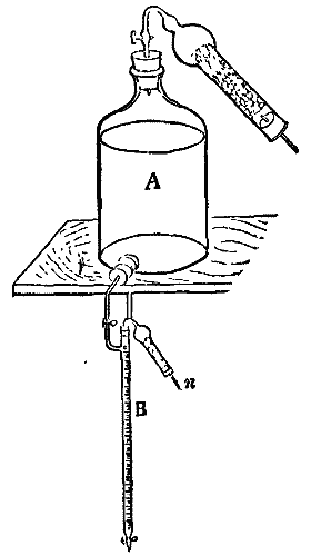
Titrating apparatus
Titration setup
The author also describes the apparatus he employs for storing and titrating with baryta solution. The latter is contained in the bottle, A, and the drying tube attached to the neck of the same is filled with quicklime. The burette, B, which is in direct connection with the bottle, may be filled with the solution by opening the stop cock, and the small drying tube, n, is filled with dry KOH, thus preventing the entrance of any CO2. Numbers are appended which seem to testify to the excellence of the method employed. The author finally gives a detailed account of the entire analysis of various cereals.—A.R. in Jour. Soc. Chem. Indus.
The author also describes the setup he uses for storing and titrating with baryta solution. The solution is held in bottle A, and the drying tube attached to its neck is filled with quicklime. The burette, B, which is directly connected to the bottle, can be filled with the solution by opening the stopcock, and the small drying tube, n, is filled with dry KOH, preventing the entry of any CO2. Numbers are included that seem to prove the effectiveness of the method used. Finally, the author provides a detailed account of the complete analysis of various cereals.—A.R. in Jour. Soc. Chem. Indus.
SYNTHESIS OF THE ALKALOIDS.
In the note on the constitution of alkaloids in a recent issue, we referred more especially to what we may term the less highly organized bases. Most of our knowledge, as we now have it, regarding such alkaloids as muscarine and choline has been acquired during the past dozen years. This is not exactly the case with the higher groups of alkaloids—the derivatives of pyridine and quinoline. It so happens that the oldest alkaloids are in these groups. They have, almost necessarily, been subjected to a longer period of attack, but the extreme complexity of their molecules, and the infinite number of differing parts or substances into which these molecules split up when attacked, are the main cause of the small progress which has been made in this department. All, however, yield one or more bodies or bases in common, while each has its distinctive and peculiar decomposition product. For example, cinchonine and quinine both afford the basic quinoline under certain conditions, but on oxidation of cinchonine, an acid—cinchoninic acid (C10H7NO2)—is the principal body formed, while in the case of quinine, quininic acid (C10H9NO3) is the principal product. The acquirement through experiment of such knowledge as that is, however, so much gained. We find, indeed, that obstacles are gradually being cleared away, and the actual synthetic formation of such alkaloids as piperidine and coniine is a proof that the chemist is on the right track in studying the decomposition products, and building up from them, theoretically, bodies of similar constitution. It is noteworthy that the synthesis of the alkaloids has led to some of the most brilliant discoveries of the present day, especially in the discovery of dye stuffs. Many of our quinine substitutes, such as thalline, for example, are the result of endeavors to make quinine artificially. If there is romance in chemistry at all, it is to be found certainly in this branch of it, which is generally considered the most uninteresting and unfathomable. We may take piperidine and coniine as examples of the methods followed in alkaloidal synthesis; these are pyridine bases. Pyridine has the formula C5H5N, that is, it is benzene with CH replaced by N. The relationship between these and piperidine is seen in the following formulæ:
In the note on the structure of alkaloids in a recent issue, we specifically mentioned what we might call the less complex bases. Most of what we currently know about alkaloids like muscarine and choline has been learned in the last twelve years. This isn’t quite true for the higher groups of alkaloids—the derivatives of pyridine and quinoline. Interestingly, the oldest alkaloids fall into these groups. They have, almost necessarily, faced a longer period of research, but the extreme complexity of their molecules and the countless different parts or substances that these molecules break down into when studied are the main reasons for the slow progress in this area. Still, all of them produce one or more common bases, while each has its unique and specific breakdown product. For instance, both cinchonine and quinine can produce the basic quinoline under certain conditions, but when cinchonine is oxidized, it primarily forms an acid—cinchoninic acid (C10H7NO2)—while in the case of quinine, it produces quininic acid (C10H9NO3). Gaining knowledge through experimentation like this is a significant achievement. Indeed, we see that obstacles are gradually being removed, and the actual synthetic creation of alkaloids like piperidine and coniine shows that chemists are on the right path in studying the breakdown products and theorizing similar compounds based on them. It’s worth noting that the synthesis of alkaloids has led to some of the most impressive discoveries today, especially in the realm of dyes. Many of our substitutes for quinine, such as thalline, for example, are the result of efforts to artificially create quinine. If there’s any romance in chemistry, it certainly lies in this area, which is usually regarded as the most boring and difficult to understand. We can consider piperidine and coniine as examples of the methods used in alkaloid synthesis; both are pyridine bases. Pyridine has the formula C5H5N, meaning it’s benzene with CH replaced by N. The relationship between these and piperidine is illustrated in the following formulas:

If we introduce six hydrogen atoms into pyridine, we convert it into piperidine. Ladenburg succeeded in so hydrogenizing pyridine by acting upon an alcoholic solution with sodium, and from the base which was formed he obtained a platinochloride which agreed with the similar double salt of piperidine. He has also prepared it from trimethyline cyanide by the action of sodium. Pentamethylinediamine is the principal intermediary product, and this gives piperidine when distilled with superheated steam. He has proved that the alkaloid so obtained is identical with that prepared from piperine. Another curious point which Ladenburg has lately proved is that cadaverine (one of the products of flesh decomposition) is identical with pentamethylinediamine, and that its imine is the same as piperidine. The synthesis of coniine by Ladenburg is one of the most notable achievements of modern chemistry. He at first supposed that this alkaloid was piperidine in which two hydrogen atoms were replaced by the isopropyl radical (C3H7), its formula being taken as C5H9(C3H7)NH. But he has since changed his view, as will be seen from what follows. In its synthesis 1,000 grammes of picoline were first converted into alphapicoline, 380 grammes being obtained. This was heated with paraldehyde, whereby it was converted into allylpyridine (48 grammes), and this by reduction with sodium yielded alpha-propylpyridine, a body in almost every respect identical with coniine. The more important difference was its optical inactivity, but he succeeded in splitting up a solution of the acid tartrate of the base by means of Penicillium glaucum. Crystals separated which had a dextro-rotatory power of [a]D = 31° 87' as compared with the [a]D = 13° 79' of natural coniine. This brief account conveys but a faint idea of the difficulties which were encountered in these researches. Optical methods of examination have proved of great value, and are destined to play an important part in such work.
If we add six hydrogen atoms to pyridine, we turn it into piperidine. Ladenburg managed to hydrogenate pyridine by treating an alcoholic solution with sodium, and from the resulting base, he obtained a platinochloride that matched the similar double salt of piperidine. He also produced it from trimethyline cyanide using sodium. The main intermediate product is pentamethylinediamine, which yields piperidine when distilled with superheated steam. He demonstrated that the alkaloid produced is the same as that derived from piperine. Another interesting point that Ladenburg recently established is that cadaverine (one of the substances produced during the decay of flesh) is identical to pentamethylinediamine, and that its imine is the same as piperidine. Ladenburg's synthesis of coniine is one of the most significant accomplishments in modern chemistry. Initially, he thought this alkaloid was piperidine with two hydrogen atoms replaced by the isopropyl radical (C3H7), with its formula being C5H9(C3H7)NH. However, he has since revised his perspective, as will be noted in the following details. In its synthesis, 1,000 grams of picoline were first converted into alphapicoline, yielding 380 grams. This was heated with paraldehyde, transforming it into allylpyridine (48 grams), and this was reduced with sodium to produce alpha-propylpyridine, a compound that is almost identical to coniine. The main difference was its optical inactivity, but he managed to break down a solution of the acid tartrate of the base using Penicillium glaucum. Crystals formed that had a dextro-rotatory power of [a]D = 31° 87' compared to the [a]D = 13° 79' of natural coniine. This brief overview gives only a hint of the challenges faced in these studies. Optical examination methods have proven to be extremely valuable and are expected to play a crucial role in similar research.
Among the most complex alkaloids are those of the quinine group. As yet chemists have got no further with these than the oxidation products; but the study has afforded us several new antipyretics and many interesting facts. It has been found, for example, that artificial quinine-like bodies, which fluoresce and give the green color with chlorine water and ammonia, have antipyretic properties like quinine, but their secondary effects are so pernicious as to prevent their use. If, however, such bodies are hydrogenized or methylated they lose their fluorescing property, do not give the green color, and their secondary effects are removed. Knowledge of these facts led to the discovery of thalline. It is prepared from paraquinanisol, one of the objectionable bodies, by reduction with tin and hydrochloric acid. The following formulæ show the constitutional relationship of these compounds:
Among the most complex alkaloids are those in the quinine group. Chemists have only made progress with the oxidation products so far, but this research has resulted in several new antipyretics and many interesting findings. For instance, it has been discovered that artificial quinine-like compounds, which fluoresce and produce a green color when mixed with chlorine water and ammonia, have antipyretic properties similar to quinine; however, their harmful side effects make them impractical for use. Yet, when these compounds are hydrogenated or methylated, they lose their fluorescent property, do not produce the green color, and their harmful side effects are eliminated. Understanding these facts led to the discovery of thalline. It is made from paraquinanisol, one of the problematic compounds, through reduction with tin and hydrochloric acid. The formulas below show the structural relationship of these compounds:

It is evident from the difficulties which have been encountered in this department of chemistry, and more especially from the costly nature of the work, that it will be many years before it will influence the manufacture of alkaloids from the drugs which yield them. Ladenburg has synthetized coniine, but he has not yet ventured to assert that his product will replace the natural alkaloid.—Chem. and Druggist.
It is clear from the challenges faced in this area of chemistry, particularly due to the expensive nature of the work, that it will take many years before it affects the production of alkaloids from the plants that produce them. Ladenburg has synthesized coniine, but he has not yet claimed that his product will replace the natural alkaloid.—Chem. and Druggist.
The Southern California Advocate reports another magnificent donation of lands to the University of Southern California by Mr. D. Freeman, the owner of the Centinella ranch near Los Angeles—six hundred thousand dollars in all given to found a school of applied sciences, $100,000 for building and apparatus and $500,000 for endowment. The buildings will be in the vicinity of Inglewood, the new and beautiful town on the Ballona branch of the California Central.
The Southern California Advocate reports another amazing donation of land to the University of Southern California by Mr. D. Freeman, the owner of the Centinella ranch near Los Angeles—totaling six hundred thousand dollars to establish a school of applied sciences, with $100,000 designated for building and equipment and $500,000 for the endowment. The buildings will be located near Inglewood, the new and beautiful town on the Ballona branch of the California Central.
A GROUP OF HAMPSHIRE DOWNS.

The Hampshire Down breed of sheep originated about 80 years ago by a cross of South Downs on the horned, white-faced sheep which had for ages been native of the open, untilled, hilly stretch of land known as the Hampshire Downs, in the county of that name bordering on the English Channel, in the South of England. From time immemorial the South Downs had dark brown or black legs, matured early, produced the best of mutton and a fine quality of medium wool. The original Hampshire was larger, coarser, but hardier, slower to mature, with inferior flesh, and a longer but coarser wool. The South Down has always been remarkable for its power of transmitting its special characteristics to its progeny by other kinds of sheep, and hence it soon impressed its own characteristics on its progeny by the Hampshire. The horns of the original breed have disappeared; the face and legs have become dark, the frame has become more compact, the bones smaller, the back broader and straighter, the legs shorter, and the flesh and wool of better quality, while the superior hardiness and greater size, as well as the large head and Roman nose of the old breed, still remain. The Hampshires of to-day mature early and fatten readily. They clip from six to seven pounds of wool, suitable for combing, which is longer than South Down wool, but less fine. The mutton has a desirable proportion of fat and lean, and is juicy and fine flavored. The lambs are of large size and are usually dropped early and fed for market. Indeed, the Hampshire may be considered a larger and trifle coarser and hardier South Down. The breed is occasionally crossed with Cotswolds, when it produces a wool more valuable for worsted manufacturers than the pure Cotswold. Indeed, there is little doubt that in addition to South Down, the Hampshire has a dash of Cotswold blood in its composition. Considerable importations of the breed have been made into this country, but it has not become so popular as the South Down and some other English breeds. The excellent group shown is owned by Mr. James Wood, of Mount Kisco, New York.—Rural New-Yorker.
The Hampshire Down breed of sheep started about 80 years ago from a cross between South Downs and the horned, white-faced sheep that had long been native to the open, uncultivated, hilly area known as the Hampshire Downs, located in the county of the same name by the English Channel in southern England. For ages, the South Downs had dark brown or black legs, matured quickly, produced top-quality mutton, and had a fine medium wool. The original Hampshire was larger and coarser but hardier, took longer to mature, had poorer-quality meat, and produced longer but coarser wool. The South Down has always been known for passing its unique traits onto other breeds, and it soon imparted its characteristics to the Hampshire offspring. The horns of the original breed have vanished; the face and legs have darkened, the body has become more compact, the bones smaller, the back broader and straighter, the legs shorter, and both the meat and wool quality have improved, while the hardiness and larger size, as well as the big head and Roman nose of the old breed, are still present. Today's Hampshires mature quickly and gain weight easily. They yield between six to seven pounds of wool suitable for combing, which is longer than South Down wool but not as fine. The mutton has a desirable balance of fat and lean meat, and it is juicy and flavorful. The lambs are large and usually born early for market feeding. In fact, the Hampshire can be seen as a larger, slightly coarser, and hardier version of the South Down. The breed is sometimes crossed with Cotswolds, resulting in wool that is more valuable for worsted production than pure Cotswold wool. It’s quite likely that alongside South Down, the Hampshire also has some Cotswold heritage. Many imports of this breed have been brought into the country, but it hasn’t gained the popularity of South Down and some other English breeds. The excellent group shown is owned by Mr. James Wood of Mount Kisco, New York.—Rural New-Yorker.
THE YALE COLLEGE MEASUREMENT OF THE PLEIADES.1
The Messrs. Repsold have established, and for the present seem likely to maintain, a practical monopoly in the construction of heliometers. That completed by them for the observatory of Yale College in 1882 leaves so little to be desired as to show excellence not to be the exclusive result of competition. In mere size it does not indeed take the highest rank. Its aperture is of only six inches, while that of the Oxford heliometer is of seven and a half; but the perfection of the arrangements adapting it to the twofold function of equatorial and micrometer stamps it as a model not easy to be surpassed. Steel has been almost exclusively used in the mounting. Recommended as the material for the objective cell by its quality of changing volume under variations of temperature nearly paripassu with glass, its employment was extended to the telescope tube and other portions of the mechanism. The optical part of the work was done by Merz, Alvan Clark having declined the responsibility of dividing the object lens. Its segments are separable to the extent of 2°, and through the contrivance of cylindrical slides (originally suggested by Bessel) perfect definition is preserved in all positions, giving a range of accurate measurement just six times that with a filar micrometer. (Gill, "Encyc. Brit.," vol. xvi., p. 253; Fischer, Sirius, vol. xvii., p. 145.)
The Repsold brothers have created, and for now seem likely to keep, a practical monopoly on making heliometers. The one they completed for Yale College's observatory in 1882 is so impressive that it shows excellence isn't just the result of competition. In terms of size, it doesn't take the top spot. Its aperture is only six inches, while the Oxford heliometer has an aperture of seven and a half. However, the way it’s designed for both equatorial and micrometer functions makes it a tough model to beat. Steel has been used almost exclusively for the mounting. It was recommended as the best material for the objective cell because its volume changes with temperature almost like glass, and this usage extended to the telescope tube and other parts of the mechanism. The optical work was done by Merz, as Alvan Clark declined to take responsibility for splitting the object lens. Its segments can be separated by up to 2°, and thanks to cylindrical slides (originally suggested by Bessel), perfect definition is maintained in all positions, providing a measurement accuracy range that is six times greater than that of a filar micrometer. (Gill, "Encyc. Brit.," vol. xvi., p. 253; Fischer, Sirius, vol. xvii., p. 145.)
This beautiful engine of research was in 1883 placed in the already practiced and skillful hands of Dr. Elkin. He lost no time in fixing upon a task suited both to test the powers of the new instrument and to employ them to the highest advantage.
This impressive research engine was put in the capable hands of Dr. Elkin in 1883. He quickly chose a task that would both test the capabilities of the new instrument and make the most of them.
The stars of the Pleiades have, from the earliest times, attracted the special notice of observers, whether savage or civilized. Hence, on the one hand, their prominence in stellar mythology all over the world; on the other, their unique interest for purposes of scientific study and comparison. They constitute an undoubted cluster; that is to say, they are really, and not simply in appearance, grouped together in space, so as to fall under the sway of prevailing mutual influences. And since there is, perhaps, no other stellar cluster so near the sun, the chance of perceptible displacements among them in a moderate lapse of time is greater than in any other similar case. Authentic data regarding them, besides, have now been so long garnered that their fruit may confidently be expected at least to begin to ripen.
The stars of the Pleiades have captured the attention of observers, both primitive and advanced, from ancient times. This has led to their prominence in star mythology worldwide, as well as their unique significance for scientific study and comparison. They form a definite cluster; meaning they are genuinely grouped together in space, not just appearing to be so, and are influenced by one another. Since there might not be another stellar cluster this close to the sun, the likelihood of noticeable movement among them over a reasonable time period is higher than in any other similar situation. Additionally, extensive data about them has been collected for such a long time that we can confidently expect to start seeing results soon.
Dr. Elkin determined, accordingly, to repeat the survey of the Pleiades executed by Bessel at Konigsberg during about twelve years previous to 1841. Wolf and Pritchard had, it is true, been beforehand with him; but the wide scattering of the grouped stars puts the filar micrometer at a disadvantage in measuring them, producing minute errors which the arduous conditions of the problem render of serious account. The heliometer, there can be no doubt, is the special instrument for the purpose, and it was, moreover, that employed by Bessel; so that the Konigsberg and Yale results are comparable in a stricter sense than any others so far obtained.
Dr. Elkin decided to redo the survey of the Pleiades that Bessel conducted in Konigsberg about twelve years before 1841. It's true that Wolf and Pritchard had already done their work, but the stars are so widely scattered that using a filar micrometer to measure them has its challenges, resulting in small errors that are significant given the difficulty of the problem. There's no doubt that the heliometer is the best tool for this task, and it was also the one used by Bessel. This makes the results from Konigsberg and Yale more directly comparable than any others gathered up to this point.
One of Bessel's fifty-three stars was omitted by Dr. Elkin as too faint for accurate determination. He added, however, seventeen stars from the Bonn Durchmusterung, so that his list comprised sixty-nine, down to 9.2 magnitude. Two independent triangulations were executed by him in 1884-85. For the first, four stars situated near the outskirts of the group, and marking the angles of quadrilateral by which it was inclosed, were chosen as reference points. The second rested upon measures of distance and position angle outward from Alcyone (η Tauri). Thus, two wholly unconnected sets of positions were secured, the close accordance of which testified strongly to the high quality of the entire work. They were combined, with nearly equal weights, in the final results. A fresh reduction of the Konigsberg observations, necessitated by recent improvements in the value of some of the corrections employed, was the preliminary to their comparison with those made, after an interval of forty-five years, at Yale College. The conclusions thus laboriously arrived at are not devoid of significance, and appear perfectly secure, so far as they go.
One of Bessel's fifty-three stars was left out by Dr. Elkin because it was too faint for accurate measurement. However, he added seventeen stars from the Bonn Durchmusterung, so his list included sixty-nine stars, down to magnitude 9.2. He conducted two separate triangulations in 1884-85. For the first, he chose four stars located near the edges of the group, which marked the corners of the quadrilateral enclosing it, as reference points. The second triangulation was based on distance and position angle measurements from Alcyone (η Tauri). This resulted in two completely independent sets of positions, which matched closely and strongly indicated the high quality of the overall work. They were combined with nearly equal weights in the final results. A new reduction of the Konigsberg observations was necessary due to recent improvements in the values of some corrections used, and this was the first step before comparing them with those made, after a gap of forty-five years, at Yale College. The conclusions reached through this careful work are significant and appear to be reliable, at least for what they provide.
It has been known for some time that the stars of the Pleiades possess a small identical proper motion. Its direction, as ascertained by Newcomb in 1878, is about south-southeast; its amount is somewhat less than six seconds of arc in a century. The double star 61 Cygni, in fact, is displaced very nearly as much in one year as Alcyone with its train in one hundred. Nor is there much probability that this slow secular shifting is other than apparent; since it pretty accurately reverses the course of the sun's translation through space, it may be presumed that the backward current of movement in which the Pleiades seem to float is purely an effect of our own onward traveling.
It has been known for some time that the stars of the Pleiades have a similar proper motion. Its direction, determined by Newcomb in 1878, is roughly south-southeast; its amount is slightly less than six seconds of arc per century. The double star 61 Cygni, in fact, shifts almost as much in one year as Alcyone does with its group in one hundred years. There is also little chance that this slow, long-term shift is anything but apparent; since it nearly reverses the way the sun moves through space, it can be assumed that the backward motion of the Pleiades is simply a result of our own forward travel.
Now the curious fact emerges from Dr. Elkin's inquiries that six of Bessel's stars are exempt from the general drift of the group. They are being progressively left behind. The inference is obvious that they do not in reality belong to, but are merely accidentally projected upon, it; or, rather, that it is projected upon them; for their apparent immobility (which, in two of the six, may be called absolute) shows them with tolerable certainty to be indefinitely more remote—so remote that the path, moderately estimated at 21,000,000,000 miles in length, traversed by the solar system during the forty-five years elapsed since the Konigsberg measures dwindles into visual insensibility when beheld from them. The brightest of these six far-off stars is just above the eighth (7.9) magnitude; the others range from 8.5 down to below the ninth.
Now, the interesting fact that comes from Dr. Elkin's research is that six of Bessel's stars don't follow the general movement of the group. They're gradually being left behind. The conclusion is clear: they don't actually belong to it but are just randomly projected onto it; or rather, the group is projected onto them. Their apparent stillness (which, in two of the six, could be described as absolute) suggests pretty convincingly that they are vastly more distant—so distant that the path, estimated to be about 21,000,000,000 miles long, traveled by the solar system over the past forty-five years since the Konigsberg measurements becomes almost invisible when viewed from their perspective. The brightest of these six distant stars is just above the eighth magnitude (7.9); the others range from 8.5 down to below the ninth.
A chart of the relative displacements indicated for Bessel's stars by the differences in their inter-mutual positions as determined at Konigsberg and Yale accompanies the paper before us. Divergences exceeding 0.40" (taken as the limit of probable error) are regarded as due to real motion; and this is the case with twenty-six stars besides the half dozen already mentioned as destined deserters from the group. With these last may be associated two stars surmised, for an opposite reason, to stand aloof from it. Instead of tarrying behind, they are hurrying on in front.
A chart showing the relative movements of Bessel's stars, based on the differences in their positions as determined at Konigsberg and Yale, accompanies the paper we have. Differences greater than 0.40" (considered the limit of possible error) are seen as genuine motion; this applies to twenty-six stars in addition to the half dozen already mentioned as likely to leave the group. Along with these, two stars are thought to be distancing themselves for the opposite reason. Instead of lagging behind, they are speeding ahead.
An excess of the proper movement of their companions belongs to them; and since that movement is presumably an effect of secular parallax, we are justified in inferring their possession of an extra share of it to signify their greater proximity to the sun. Hence, of all the stars in the Pleiades these are the most likely to have a measurable annual parallax. One is a star a little above the seventh magnitude, distinguished as s Pleiadum; the other, of about the eighth, is numbered 25 in Bessel's list. Dr. Elkin has not omitted to remark that the conjecture of their disconnection from the cluster is confirmed by the circumstance that its typical spectrum (as shown on Prof. Pickering's plates) is varied in s by the marked character of the K line. The spectrum of its fellow traveler (No. 25) is still undetermined.
An excess of the proper movement of their companions is attributed to them; and since that movement is likely a result of secular parallax, we can reasonably conclude that they have a greater share of it, indicating their closer proximity to the sun. Therefore, among all the stars in the Pleiades, these are the most likely to exhibit a measurable annual parallax. One is a star just above the seventh magnitude, known as s Pleiadum; the other, around the eighth magnitude, is listed as 25 in Bessel's catalog. Dr. Elkin has noted that the theory of their disconnection from the cluster is supported by the fact that its typical spectrum (as shown on Prof. Pickering's plates) is distinctive in s due to the prominent K line. The spectrum of its companion (No. 25) is still not determined.
It is improbable, however, that even these nearer stars are practicable subjects for the direct determination of annual parallax. By indirect means, however, we can obtain some idea of their distance. All that we want to know for the purpose is the rate of the sun's motion; its direction we may consider as given with approximate accuracy by Airy's investigation. Now, spectroscopic measurements of stellar movements of approach and recession will eventually afford ample materials from which to deduce the solar, velocity; though they are as yet not accurate or numerous enough to found any definitive conclusion upon. Nevertheless, M. Homann's preliminary result of fifteen miles a second as the speed with which our system travels in its vast orbit inspires confidence both from the trustworthiness of the determinations (Mr. Seabroke's) serving as its basis and from its intrinsic probability. Accepting it provisionally, we find the parallax of Alcyone = about 0.02', implying a distance of 954,000,000,000,000 miles and a light journey of 163 years. It is assumed that the whole of its proper motion of 2.61' in forty-five years is the visual projection of oar own movement toward a point in R.A. 261°, Decl. +25°.
It’s unlikely that even these closer stars can be effectively used for directly measuring annual parallax. However, we can get an idea of their distance through indirect methods. What we need to know for this is the rate of the sun's motion; we can consider its direction to be approximately accurate based on Airy's investigation. Now, spectroscopic measurements of how stars move closer or further away will eventually provide plenty of information to calculate the solar velocity; although, currently, they aren't accurate or numerous enough to draw any definitive conclusions. Still, M. Homann's preliminary estimate of fifteen miles per second as the speed at which our solar system travels in its vast orbit gives us confidence, both due to the reliability of the data (Mr. Seabroke's) that underpins it and because it seems plausible. Accepting it provisionally, we find that the parallax of Alcyone is about 0.02', indicating a distance of 954 trillion miles and a light travel time of 163 years. It is assumed that the entire proper motion of 2.61' over forty-five years is the visual result of our own movement toward a point at R.A. 261°, Decl. +25°.
Thus the parallax of the two stars which we suspect to lie between us and the stars forming the genuine group of the Pleiades, at perhaps two-thirds of their distance, can hardly exceed 0.03'. This is just half that found by Dr. Gill for ξ Toucani, which may be regarded as, up to this, the smallest annual displacement at all satisfactorily determined. And the error of the present estimate is more likely to be on the side of excess than of defect. That is, the stars in question can hardly be much nearer to us than is implied by an annual parallax of 0.03", and they may be considerably more remote.
Thus, the parallax of the two stars that we think are located between us and the stars that make up the actual group of the Pleiades, at about two-thirds of their distance, is unlikely to be more than 0.03'. This is exactly half of what Dr. Gill found for ξ Toucani, which can be considered the smallest annual displacement that has been satisfactorily determined so far. Additionally, the error in this current estimate is probably more on the side of being too high than too low. This means the stars in question are unlikely to be much closer to us than what a 0.03" annual parallax suggests, and they could be significantly farther away.
Dr. Elkin concludes, from the minuteness of the detected changes of position among the Pleiades, that "the hopes of obtaining any clew to the internal mechanism of this cluster seem not likely to be realized in an immediate future;" remarking further: "The bright stars in especial seem to form an almost rigid system, as for only one is there really much evidence of motion, and in this case the total amount is barely 1 per century." This one mobile member of the naked eye group is Electra; and it is noticeable that the apparent direction of its displacement favors the hypothesis of leisurely orbital circulation round the leading star. The larger movements, however, ascribed to some of the fainter associated stars are far from harmonizing with this preconceived notion of what they ought to be.
Dr. Elkin concludes, based on the small changes in position among the Pleiades, that "the hopes of finding any clues to the internal workings of this cluster don't seem likely to be fulfilled in the near future;" adding, "The bright stars in particular appear to form an almost rigid system, as there is really only one for which there is significant evidence of motion, and even then the total amount is just about 1 per century." This one mobile star in the visible group is Electra; and it's notable that the apparent direction of its movement supports the idea of a slow orbital rotation around the main star. However, the larger movements attributed to some of the fainter associated stars don't quite match this preconceived idea of what they should be.
On the contrary, so far as they are known at present, they force upon our minds the idea that the cluster may be undergoing some slow process of disintegration. M. Wolf's impression of incipient centrifugal tendencies among its components certainly derives some confirmation from Dr. Elkin's chart. Divergent movements are the most strongly marked; and the region round Alcyone suggests, at the first glance, rather a very confused area of radiation for a flight of meteors than the central seat of attraction of a revolving throng of suns.
On the other hand, as far as we know right now, they suggest to us that the cluster might be slowly breaking apart. M. Wolf's sense of emerging centrifugal forces among its members definitely gets some support from Dr. Elkin's chart. The divergent movements are the most pronounced, and at first glance, the area around Alcyone looks more like a chaotic zone of radiation for a group of meteors than the central hub of a rotating mass of suns.
There are many signs, however, that adjacent stars in the cluster do not pursue independent courses. "Community of drift" is visible in many distinct sets; while there is as yet no perceptible evidence, from orbital motion, of association into subordinate systems. The three eighth-magnitude stars, for instance, arranged in a small isosceles triangle near Alcyone, do not, as might have been expected a priori, constitute a real ternary group. They are all apparently traveling directly away from the large star close by them, in straight lines which may, of course, be the projections of closed curves; but their rates of travel are so different as to involve certain progressive separation. Obviously, the order and method of such movements as are just beginning to develop to our apprehension among the Pleiades will not prove easy to divine.—A.M. Clerke, in Nature.
There are many signs, however, that nearby stars in the cluster don't follow independent paths. "Community of drift" can be seen in several distinct groups; while there is still no clear evidence, from their orbital motion, of any association into smaller systems. The three eighth-magnitude stars, for example, arranged in a small isosceles triangle near Alcyone, don't, as one might have expected, actually form a real ternary group. They all seem to be moving directly away from the large star near them in straight lines, which could, of course, be the projections of closed curves; but their speeds are so different that they are definitely separating over time. Clearly, figuring out the order and pattern of these movements that are just starting to become apparent among the Pleiades won't be easy. —A.M. Clerke, in Nature.
"Determination of the Relative Positions of the Principal Stars in the Group of the Pleiades." By William L. Elkin. Transactions of the Astronomical Observatory of Yale University, Vol. I., Part I. (New Haven: 1887.)
"Determination of the Relative Positions of the Main Stars in the Pleiades Group." By William L. Elkin. Transactions of the Astronomical Observatory of Yale University, Vol. I., Part I. (New Haven: 1887.)
DEEP SEA DREDGINGS: EXAMINATION OF SEA BOTTOMS.
By THOMAS T.P. BRUCE WARREN.
I believe Prof. Ehrenberg was one of the first to examine, microscopically, deep sea dredgings, some of which were undertaken for the Atlantic cable expedition, 1857.
I think Prof. Ehrenberg was one of the first to look at deep-sea dredgings under a microscope, some of which were done for the Atlantic cable expedition in 1857.
I propose to deal with the bottoms brought up from tropical waters of the Atlantic, a few years ago, during certain telegraph cable operations. These soundings were made for survey purposes, and not for any biological or chemical investigations. Still I think that this imperfect record may be a useful contribution to chemical science, bearing especially on marine operations.
I want to address the seabeds that were brought up from the tropical waters of the Atlantic a few years ago during some telegraph cable work. These soundings were taken for survey purposes and not for any biological or chemical studies. However, I believe this incomplete record could still be a valuable addition to chemical science, particularly concerning marine operations.
Although there is little to be added to the chemistry of this subject, still I think there are few chemists who could successfully make an analysis of a deep sea "bottom" without some sacrifice of time and patience, to say nothing of the risk of wasting a valuable specimen.
Although there's not much to add to the chemistry of this topic, I believe there are few chemists who could effectively analyze a deep sea "bottom" without putting in some time and patience, not to mention the risk of ruining a valuable specimen.
The muds, clays, oozes, etc., from deep water are so very fine that they pass readily through the best kinds of filters, and it is necessary to wash out all traces of sea water as a preliminary. The specimen must be repeatedly washed by decantation, until the washings are perfectly free from chlorine, when the whole may be thrown onto a filter merely to drain. The turbid water which passes through is allowed to stand so that the suspended matter may settle, and after decanting the clear supernatant water, the residuum is again thrown on to the filter.
The muds, clays, and oozes from deep water are so fine that they easily pass through the best filters. It’s necessary to wash out all traces of seawater first. The sample must be repeatedly washed by decantation until the washings are completely free from chlorine. Once that’s done, it can be poured onto a filter merely to drain. The muddy water that comes through is left to sit so the suspended particles can settle. After decanting the clear water on top, the remaining material is filtered again.
The washing and getting ready for the drying oven will, in some cases, require days to carry out, if we wish to avoid losing anything.
The washing and preparing for the drying oven may take a few days, especially if we want to avoid losing anything.
So far the proceeding is exactly the same, except draining on a filter, which would be adopted for preparing for the microscope. On no account should the opportunity be missed of mounting several slides permanently for microscopic examination. Drawings or photographic enlargements will render us independent of direct microscopic appeal, which is not at all times convenient.
So far, the process is exactly the same, except for draining on a filter, which is necessary for preparing for the microscope. We should definitely take the chance to mount several slides permanently for microscopic examination. Drawings or photographic enlargements will allow us to avoid needing direct microscopic views, which aren't always convenient.
The substance, if drained and allowed to dry on the filter, will adhere most tenaciously to it, so that it is better to complete the drying in a porcelain or platinum capsule, either by swilling the filter with a jet of water or by carefully removing with a spatula. The most strenuous care must be used not to contaminate the specimen with loose fibers from the filter.
The substance, if drained and allowed to dry on the filter, will stick very firmly to it, so it's better to finish the drying in a porcelain or platinum capsule, either by rinsing the filter with a stream of water or by carefully scraping it off with a spatula. Extreme caution must be taken to avoid contaminating the sample with loose fibers from the filter.
The perfectly dried matter is best treated in exactly the same way as a residuum in water analysis. It is a common thing to ignite the residuum, and to put the loss down, if any, to water. This ought not to satisfy an accurate observer, since organic matter, carbonates—especially in presence of silica—will easily add to the loss. The best plan is to heat a small portion very cautiously, and note if any smell or alteration in color, due to carbon, etc., is perceptible, and to proceed accordingly.
The perfectly dried material should be handled just like a residue in water analysis. It's common practice to burn the residue and attribute any loss to water. However, this shouldn't satisfy a careful observer, because organic matter and carbonates—especially in the presence of silica—can easily contribute to the loss. The best approach is to carefully heat a small portion and observe if there's any smell or change in color due to carbon, etc., and act accordingly.
I have seen some very satisfactory analyses made on board ship by a skillful use of the blowpipe, where liquid reagents would be very inconvenient to employ.
I have seen some very effective analyses done on board ship through the skillful use of the blowpipe, where using liquid reagents would be quite impractical.
It will be necessary to say a few words as to the way in which soundings are made at sea. When the bottom consists of sand, mud, or other loose matter, it is easy enough to bring specimens to the surface, and, of course, we know in such a case that the bottom has been reached, but, in the event of the bottom being hard and rocky, it is not easy to say that our sounding has been successful: and here we meet with a difficulty which unfortunately is most unsatisfactorily provided for.
It’s important to discuss how soundings are taken at sea. When the seafloor is made up of sand, mud, or other loose materials, it’s fairly simple to bring samples to the surface, and we can be sure that we’ve reached the bottom. However, when the bottom is hard and rocky, it’s difficult to confirm that our sounding has been successful, and this poses a challenge that is unfortunately not well addressed.
The lead is "cast," as the saying goes, "armed" for this emergency. An iron sinker is made with a hollow recess in the bottom; this is filled in with tallow, and on striking the bottom any loose matter may adhere by being pressed into the tallow. If the bottom is rocky or hard we get simply an imprint in the arming, and when such a result is obtained the usual construction is that "the bottom is rocky" or hard.
The lead is "cast," as they say, "prepared" for this emergency. An iron sinker has a hollow space at the bottom, which is filled with tallow. When it hits the bottom, any loose material can stick to it by being pressed into the tallow. If the bottom is rocky or hard, we only get an impression in the tallow, and when this happens, it’s typically concluded that "the bottom is rocky" or hard.
Now, this seems to me a point on which chemistry may give some very valuable help, for I am convinced that no sounding should be accepted unless evidence of the bottom itself is obtained. A few considerations will show that when we are working in very deep water, where there is a difficulty of knowing for certain that we have an "up and down" sounding, and the hardening of the "arming" by the cold and pressure, unless we bring up something we cannot be sure that we have touched the bottom; leaving the doubt on this point on one side, unless we use a very heavy sinker, so as to get an indication of the released strain when it touches the bottom, we encounter another complication.
Now, it seems to me that chemistry could offer some valuable support here, because I'm convinced that no sounding should be accepted unless we obtain evidence of the bottom itself. A few points will show that when we're working in very deep water, where it’s hard to confirm that we have an "up and down" sounding, and the "arming" hardens due to cold and pressure, we can't be sure we've actually hit the bottom unless we bring something up. Setting that doubt aside, unless we use a very heavy sinker to get an indication of the strain released when it touches the bottom, we face another complication.
Sir William Thomson's sounding wire has added the element of reliability to our soundings in this latter case. The note given out by the wire when the bottom is reached is perceptibly different when under strain, even if the dynamometer should give an unreliable indication.
Sir William Thomson's sounding wire has made our soundings much more reliable in this case. The sound emitted by the wire when it reaches the bottom is noticeably different when under tension, even if the dynamometer provides an inaccurate reading.
It has been found that when a "bottom" has been recovered by the arming with tallow, the adherent grease seriously detracts from the value of the specimen for scientific purposes. Washing with perfectly pure bisulphide carbon will save the sounding, but of course any living organism is destroyed. As we have plenty of contrivances for bringing up loose "bottoms" without arming, we have nothing to fear on this score.
It has been discovered that when a "bottom" has been recovered by using tallow, the sticking grease greatly reduces the specimen's value for scientific purposes. Washing with completely pure carbon disulfide will preserve the sample, but unfortunately, any living organisms will be destroyed. Since we have plenty of tools for bringing up loose "bottoms" without using tallow, we have nothing to worry about on this front.
There is a great difficulty to explain the vast accumulations of clay deposits on the ocean bed, and it has been suggested that some minute organisms may produce these deposits, as others give us carbonate of lime. Is there not a very great probability of some of the apparently insoluble rocky formations being answerable for these accumulations?
There is a significant challenge in explaining the massive clay deposits on the ocean floor, and it's been proposed that some tiny organisms might create these deposits, just as others produce calcium carbonate. Isn't it very likely that some of the seemingly insoluble rock formations are responsible for these accumulations?
We must not forget the peculiar changes which such an apparently stable substance as feldspar undergoes when disintegrated and exposed to the chemical action of sea water. As these deposits contain both sodium and potassium, our chemical operations must provide for the analytical results; in other respects the analysis can be proceeded with according to the operator's analytical knowledge.
We must not overlook the unusual changes that a seemingly stable substance like feldspar experiences when it breaks down and interacts with the chemical properties of seawater. Since these deposits have both sodium and potassium, our chemical processes need to account for the analytical outcomes; in other aspects, the analysis can continue based on the operator's analytical expertise.
Few operators are aware of the usefulness of an ordinary deep sea grapnel rope, as used for cable work, in recovering specimens of the fauna of any locality. The grapnel rope should be left down for a few months, so that the denizens of the deep may get used to it and make it their place of residence and attachment. The stench caused by their decomposition, unless the rope be kept in water, when hauled up will be in a few days intolerable, even to an individual with a sea-going stomach. I tried several chemical solutions for preserving specimens thus recovered, but nothing answered so well as the water itself drawn up from the same depth as the rope was recovered from.—Chem. News.
Few operators realize how useful an ordinary deep sea grapnel rope, like those used for cable work, can be for collecting specimens of local marine life. The grapnel rope should be left underwater for a few months, allowing the deep-sea creatures to get accustomed to it and make it their home and attachment. The smell from their decay, unless the rope is kept submerged, becomes unbearable within a few days, even for someone used to the sea. I tried various chemical solutions to preserve the specimens collected this way, but nothing worked as well as the water itself brought up from the same depth as the rope. —Chem. News.
THE SCIENTIFIC AMERICAN
Architects and Builders Edition
$2.50 a Year. Single Copies, 25 cts.
$2.50 per year. Single copies, 25 cents.
This is a Special Edition of the SCIENTIFIC AMERICAN, issued monthly—on the first day of the month. Each number contains about forty large quarto pages, equal to about two hundred ordinary book pages, forming, practically, a large and splendid Magazine of Architecture, richly adorned with elegant plates in colors and with fine engravings, illustrating the most interesting examples of modern Architectural Construction and allied subjects.
This is a Special Edition of SCIENTIFIC AMERICAN, released monthly on the first day of each month. Each issue contains about forty large quarto pages, which is roughly equal to two hundred standard book pages, essentially creating a large and impressive Magazine of Architecture, beautifully featuring elegant color plates and fine engravings that showcase the most fascinating examples of modern architectural construction and related topics.
A special feature is the presentation in each number of a variety of the latest and best plans for private residences, city and country, including those of very moderate cost as well as the more expensive. Drawings in perspective and in color are given, together with full Plans, Specifications, Costs, Bills of Estimate, and Sheets of Details.
A special feature of each issue is the showcase of a variety of the latest and best designs for private homes, both urban and rural, including options that are budget-friendly as well as more upscale choices. The presentations include perspective drawings and color illustrations, along with complete plans, specifications, costs, estimates, and detail sheets.
No other building paper contains so many plans, details, and specifications regularly presented as the SCIENTIFIC AMERICAN. Hundreds of dwellings have already been erected on the various plans we have issued during the past year, and many others are in process of construction.
No other building paper has as many plans, details, and specifications consistently featured as the SCIENTIFIC AMERICAN. Hundreds of homes have already been built from the various plans we released over the past year, and many more are currently under construction.
Architects, Builders, and Owners will find this work valuable in furnishing fresh and useful suggestions. All who contemplate building or improving homes, or erecting structures of any kind, have before them in this work an almost endless series of the latest and best examples from which to make selections, thus saving time and money.
Architects, builders, and owners will find this work valuable for providing fresh and useful ideas. Anyone thinking about building or improving homes, or constructing any kind of structure, has in this work an almost endless series of the latest and best examples to choose from, saving both time and money.
Many other subjects, including Sewerage, Piping, Lighting, Warming, Ventilating, Decorating, Laying out of Grounds, etc., are illustrated. An extensive Compendium of Manufacturers' Announcements is also given, in which the most reliable and approved Building Materials, Goods, Machines, Tools, and Appliances are described and illustrated, with addresses of the makers, etc.
Many other topics, like sewage systems, plumbing, lighting, heating, ventilation, decorating, and landscaping, are covered. There’s also a comprehensive collection of manufacturers' announcements, showcasing the most reliable and reputable building materials, products, machines, tools, and appliances, along with their manufacturers' addresses, etc.
The fullness, richness, cheapness, and convenience of this work have won for it the Largest Circulation of any Architectural publication in the world
The completeness, depth, affordability, and ease of access of this work have earned it the Largest Circulation of any architectural publication in the world.
MUNN& CO., Publishers,
361 Broadway, New York.
MUNN & CO., Publishers,
361 Broadway, New York.
A Catalogue of valuable books on Architecture,
Building, Carpentry, Masonry, Heating, Warming,
Lighting, Ventilation, and all branches of industry
pertaining to the art of Building, is supplied free of
charge, sent to any address.
A catalog of valuable books on architecture, construction, carpentry, masonry, heating, warming, lighting, ventilation, and all areas of industry related to the art of building is provided free of charge and can be sent to any address.
Building Plans and Specifications.
In connection with the publication of the BUILDING EDITION of the SCIENTIFIC AMERICAN, Messrs. Munn & Co. furnish plans and specifications for buildings of every kind, including Churches, Schools, Stores, Dwellings, Carriage Houses, Barns, etc.
In relation to the release of the BUILDING EDITION of the SCIENTIFIC AMERICAN, Munn & Co. provides plans and specifications for all types of buildings, including churches, schools, stores, homes, carriage houses, barns, and more.
In this work they are assisted by able and experienced architects. Full plans, details, and specifications for the various buildings illustrated in this paper can be supplied.
In this project, they are supported by skilled and experienced architects. Complete plans, details, and specifications for the different buildings shown in this document are available.
Those who contemplate building, or who wish to alter, improve, extend, or add to existing buildings, whether wings, porches, bay windows, or attic rooms, are invited to communicate with the undersigned. Our work extends to all parts of the country. Estimates, plans, and drawings promptly prepared. Terms moderate. Address
Those who are considering building, or who want to change, improve, expand, or add to existing buildings, whether it be adding wings, porches, bay windows, or attic rooms, are encouraged to get in touch with the person listed below. Our services are available throughout the country. Estimates, plans, and drawings will be prepared quickly. Our prices are reasonable. Address
MUNN & CO., 361 BROADWAY, NEW YORK.
MUNN & CO., 361 BROADWAY, NEW YORK.
The
Scientific American Supplement.
Published Weekly.
Published Weekly.
Terms of Subscription, $5 a year.
Terms of Subscription: $5 per year.
Sent by mail, postage prepaid, to subscribers in any part of the United States or Canada. Six dollars a year, sent, prepaid, to any foreign country.
Sent by mail, with postage paid, to subscribers anywhere in the United States or Canada. Six dollars a year, sent with prepaid postage, to any foreign country.
All the back numbers of THE SUPPLEMENT, from the commencement, January 1, 1876, can be had. Price, 10 cents each.
All the back issues of THE SUPPLEMENT, starting from January 1, 1876, are available. Price: 10 cents each.
All the back volumes of THE SUPPLEMENT can likewise be supplied. Two volumes are issued yearly. Price of each volume, $2.50 stitched in paper, or $3.50 bound in stiff covers.
All the past editions of THE SUPPLEMENT are also available. Two volumes are released each year. The price for each volume is $2.50 for paper binding, or $3.50 for hardcover.
COMBINED RATES.—One copy of SCIENTIFIC AMERICAN and one copy of SCIENTIFIC AMERICAN SUPPLEMENT, one year, postpaid, $7.00.
COMBINED RATES.—One copy of SCIENTIFIC AMERICAN and one copy of SCIENTIFIC AMERICAN SUPPLEMENT, one year, shipped to you, $7.00.
A liberal discount to booksellers, news agents, and canvassers.
A generous discount for booksellers, newsagents, and canvassers.
MUNN & CO., Publishers,
361 Broadway, New York, N.Y.
MUNN & CO., Publishers,
361 Broadway, New York, NY.
PATENTS.
In connection with the Scientific American, Messrs. MUNN & Co. are solicitors of American and Foreign Patents, have had 42 years' experience, and now have the largest establishment in the world. Patents are obtained on the best terms.
In relation to the Scientific American, MUNN & Co. are agents for American and Foreign Patents, boasting 42 years of experience, and currently operate the largest establishment in the world. Patents can be secured on the best terms.
A special notice is made in the Scientific American of all inventions patented through this Agency, with the name and residence of the Patentee. By the immense circulation thus given, public attention is directed to the merits of the new patent, and sales or introduction often easily effected.
A special notice is made in the Scientific American of all inventions patented through this Agency, along with the name and address of the Patentee. The huge circulation generated draws public attention to the advantages of the new patent, making sales or introductions often much easier.
Any person who has made a new discovery or invention can ascertain, free of charge, whether a patent can probably be obtained, by writing to MUNN & CO.
Any person who has made a new discovery or invention can find out for free if they can likely get a patent by writing to MUNN & CO.
We also send free our Hand Book about the Patent Laws, Patents, Caveats, Trade Marks, their costs, and how procured. Address
We also send out our Hand Book for free, which covers Patent Laws, Patents, Caveats, Trade Marks, their costs, and how to obtain them. Address
MUNN & CO.
361 Broadway, New York.
Branch Office, 622 and 624 F St., Washington, D.C.
MUNN & CO.
361 Broadway, New York.
Branch Office, 622 and 624 F St., Washington, D.C.
Download ePUB
If you like this ebook, consider a donation!