This is a modern-English version of Scientific American Supplement, No. 443, June 28, 1884, originally written by Various.
It has been thoroughly updated, including changes to sentence structure, words, spelling,
and grammar—to ensure clarity for contemporary readers, while preserving the original spirit and nuance. If
you click on a paragraph, you will see the original text that we modified, and you can toggle between the two versions.
Scroll to the bottom of this page and you will find a free ePUB download link for this book.

SCIENTIFIC AMERICAN SUPPLEMENT NO. 443.
NEW YORK, JUNE 28, 1884.
Scientific American Supplement. Vol. XVII., No. 443.
Scientific American established 1845
Scientific American Supplement, $5 a year.
Scientific American and Supplement, $7 a year.
PUERTA DEL SOL, MADRID.
Puerta del Sol, or Gate of the Sun, Madrid, is the most famous and favorite public square in the Spanish city of Madrid. It was the eastern portal of the old city. From this square radiate several of the finest streets, such as Alcala, one of the handsomest thoroughfares in the world, Mayor, Martera, Carretas, Geronimo. In our engraving the post office is seen on the right. Large and splendid buildings adorn the other sides, which embrace hotels, cafes, reading rooms, elegant stores, etc. From this square the street railway lines traverse the city in all directions. The population of the city is about 400,000. It contains many magnificent buildings. Our engraving is from Illustrirte Zeitung.
Puerta del Sol, or Gate of the Sun, Madrid, is the most famous and beloved public square in the Spanish city of Madrid. It was the eastern entrance of the old city. From this square, several of the most beautiful streets radiate, such as Alcalá, one of the prettiest thoroughfares in the world, along with Mayor, Martera, Carretas, and Geronimo. In our engraving, you can see the post office on the right. Large and impressive buildings line the other sides, which include hotels, cafes, reading rooms, upscale shops, and more. From this square, the streetcar lines traverse the city in all directions. The city's population is about 400,000, and it features many magnificent buildings. Our engraving is from Illustrirte Zeitung.
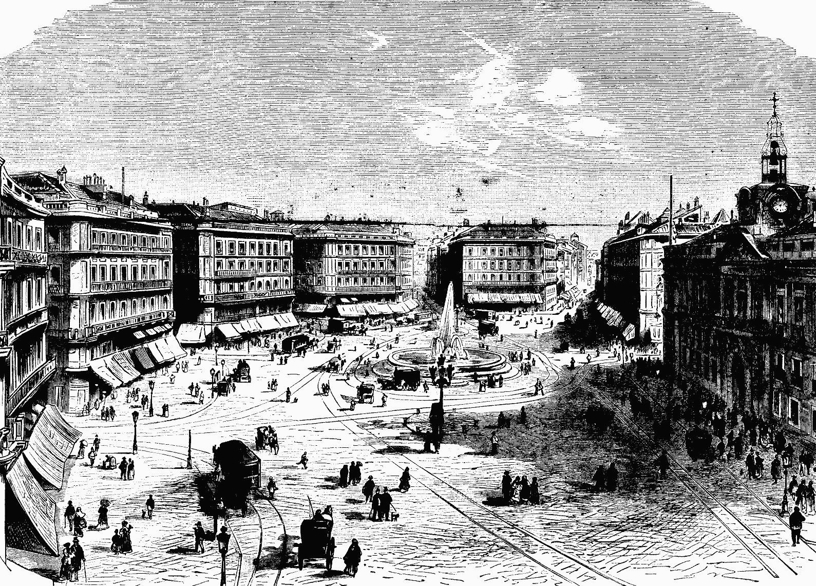
THE PUERTA DEL SOL, MADRID, SPAIN (From a Photograph.)
CONCRETE BUILDINGS FOR FARMS.
Buildings made of concrete have never received the attention in this country that they deserve. They have the merit of being durable and fire-proof, and of not being liable to be blown down by violent winds. It is very easy to erect them in places where sand and gravel are near at hand and lime is comparatively cheap. Experiments made in England show that coal screenings may be employed to good advantage in the place of sand and gravel. Mr. Samuel Preston, of Mount Carroll, Ill., has a dwelling and several other buildings made of concrete and erected by himself. They were put up in 1851, and are in excellent condition. In The Farmers' Review he gives the following directions for building concrete walls:
Buildings made of concrete have never received the attention they deserve in this country. They’re durable, fire-resistant, and won’t be easily blown down by strong winds. It’s really easy to build them where sand and gravel are available, and where lime is relatively inexpensive. Experiments in England have shown that coal screenings can be effectively used instead of sand and gravel. Mr. Samuel Preston from Mount Carroll, Illinois, has built his home and several other concrete structures himself. They were built in 1851 and are in great condition. In The Farmers' Review, he provides the following guidelines for constructing concrete walls:
First, secure a good stone foundation, the bottom below frost, the top about one foot above ground. Near the top of the foundation bed in 2×4 scantling edgewise transversely with the walls, at such distances apart as the length of the planks that form the boxes to hold the concrete may require, the ends of the scantling to run six inches beyond the outside and inside of the wall. Now take 2×6 studding, one foot longer than the height of the concrete walls are to be, bolt in an upright position in pairs to each end of the 2×4 scantling, and, if a foot wall is to be built, sixteen inches apart, as the box plank will take up four inches. To hold the studding together at the top, take pieces of 2×6 lumber, make two mortises in each piece large enough to slip easily up and down on the studding, forming a tie. Make one mortise long enough to insert a key, so that the studding can be opened at the top when the box plank are to be raised. When the box plank are in position, nail cleats with a hole in each of them on each side of the studding, and corresponding holes in the studding, into which insert a pin to hold the plank to the studding. Bore holes along up in the studding, to hold the boxes when raised.
First, establish a solid stone foundation, buried below the frost line, with the top about one foot above ground. Near the top of the foundation, place 2×4 lumber edgewise across the walls, spaced apart according to the length of the planks used to create the forms for the concrete. The ends of the lumber should extend six inches beyond both the outside and inside of the wall. Next, use 2×6 studs that are one foot longer than the planned height of the concrete walls and bolt them upright in pairs at each end of the 2×4 lumber. If you're building a foot-high wall, place the studs sixteen inches apart, as the form planks will take up four inches. To secure the studs at the top, use pieces of 2×6 lumber, making two mortises in each piece big enough to slide easily up and down the studs, forming a tie. Make one mortise long enough to insert a key, allowing the studs to be opened at the top when the form planks need to be raised. Once the form planks are in place, attach cleats with a hole in each on both sides of the studs, and drill corresponding holes in the studs for pins to hold the planks. Drill holes up the studs to secure the forms when raised.
To make the walls hollow, and I would do it in a building for any purpose, use inch boards the same width of the box plank, one side planed; put the two rough sides together with shingles between, nailing them together with six-penny nails; place them in the middle of the wall, the thin end of the shingle down. That gives them a bevel and can be easily raised with the boxes. To tie the wall together, at every third course place strips of boards a little shorter than the thickness of the wall; cut notches in each so that the concrete will fill in, holding all fast. The side walls being up, place two inch planks on top of the wall upon which to rest the upper joists, put on joist and rafters, remove the box plank, take inch boards for boxes, cut to fit between joists and rafters, and fill with concrete to upper side of rafters, which makes walls that will keep out cold and damp, all kinds of vermin, and a roof which nothing but a cyclone can remove. In making door and window frames, make the jambs two inches narrower than the thickness of the walls, nailing on temporary two inch strips.
To create hollow walls in any type of building, use inch-wide boards that match the width of the box plank, with one side smoothed out. Place the two rough sides together with shingles in between, and nail them with six-penny nails. Position this assembly in the center of the wall, with the thin end of the shingle facing down. This design provides a bevel that can be easily lifted with the boxes. To reinforce the wall, place strips of boards every third course that are slightly shorter than the wall's thickness; cut notches in each so the concrete can flow in, securing everything. Once the side walls are up, lay two-inch planks on top of the wall to support the upper joists, then add the joists and rafters. Remove the box plank and use inch boards for boxes, cutting them to fit between the joists and rafters and filling them with concrete up to the top of the rafters. This creates walls that keep out cold, dampness, and all kinds of pests, along with a roof that only a cyclone could dislodge. When constructing door and window frames, make the jambs two inches narrower than the wall thickness and attach temporary two-inch strips.
Make the mortar bed large enough to hold the material for one course; put in unslaked quicklime in proportion to 1 to 20 or 30 of other material; throw into it plenty of water, and don't have that antediluvian idea that you can drown it; put in clean sand and gravel, broken stone, making it thin enough, so that when it is put into boxes the thinner portion will run in, filling all interstices, forming a solid mass. A brick trowel is necessary to work it down alongside the boxing plank. One of the best and easiest things to carry the concrete to the boxes is a railroad wheelbarrow, scooping it in with a scoop shovel. Two courses a week is about as fast as it will be safe to lay up the walls.
Make the mortar bed large enough to hold the material for one layer; add unslaked quicklime in a ratio of 1 part to 20 or 30 parts of other materials; pour in plenty of water, and don’t hold onto the outdated belief that you can drown it; mix in clean sand and gravel, and broken stone, making it thin enough so that when it’s placed into the boxes, the thinner parts will flow in, filling all the gaps and creating a solid mass. You’ll need a brick trowel to work it down alongside the boxing plank. One of the best and easiest ways to transport the concrete to the boxes is using a railroad wheelbarrow, scooping it in with a shovel. Two layers a week is about as fast as it will be safe to build up the walls.
The Medical Summary recommends the external use of buttermilk to ladies who are exposed to tan or freckles.
The Medical Summary recommends using buttermilk externally for women who are exposed to tanning or freckles.
WHAT CAUSES PAINT TO BLISTER AND PEEL?
HOW TO PREVENT IT.
This subject has been treated by many, but out of the numerous ideas that have been brought to bear upon it, the writers have failed to elucidate the question fully, probably owing to the fact that in most parts they were themselves dubious as to the real cause. Last year W.S. gave a lengthy description in the Building News, in which he classified blistering and peeling of paint into one of blistering only. He stated in the beginning of his treatise the following:
This topic has been addressed by many, but despite the variety of ideas presented, the authors haven't fully clarified the issue, likely because they were uncertain about the actual cause. Last year, W.S. provided an extensive description in the Building News, where he categorized the blistering and peeling of paint into just one type of blistering. He began his discussion with the following statement:
"The subject of blistering of paint has from time to time engrossed the attention of practical men; but so far as we can follow it in the literature pertaining to the building trade, its cause has never been clearly laid down, and hence it is a detail enshrouded in mystery."
"The issue of paint blistering has occasionally captured the interest of professionals; however, as far as we can trace in the building trade literature, its cause has never been clearly defined, making it a detail shrouded in mystery."
W.S. dwells mostly, in his following explanations on blistering paints, on steam raised in damp wood. Also an English painter, according to the Painters' Journal, lately reiterates the same theory, and gives sundry reasons how water will get into wood through paint, but is oblivious that the channels which lead water into wood are open to let it out again. He lays great stress on boiled oil holding water in suspense to cause blistering, which is merely a conjecture. Water boils at 212° F. and linseed oil at 600° F., consequently no water can possibly remain after boiling, and a drop of water put into boiling oil would cause an explosion too dangerous to be encountered.
W.S. mostly focuses, in his upcoming explanations about blistering paints, on steam generated in damp wood. An English painter, according to the Painters' Journal, recently reiterated the same theory and provided several reasons for how water can enter wood through paint, but fails to realize that the channels allowing water into the wood are also open to let it out. He emphasizes that boiled oil can trap water, leading to blistering, which is simply a guess. Water boils at 212°F, while linseed oil boils at 600°F; therefore, no water could remain after boiling, and a drop of water added to boiling oil would cause an explosion too dangerous to risk.
It will be shown herewith that boiled oil, though in general use, is unfit for durable painting, that it is the cause of most of the troubles painters have to contend with, and that raw linseed oil seasoned by age is the only source to bind pigments for durable painting; but how to procure it is another trouble to overcome, as all our American raw linseed oil has been heated by the manufacturers, to qualify it for quick drying and an early market, thereby impairing its quality. After linseed oil has been boiled, it becomes a poor varnish; it remains soft and pliable when used in paint, giving way to air pressure from the wood in hot weather, forming blisters. Turpentine causes no blistering; it evaporates upon being exposed, and leaves the paint in a porous condition for the gas in the wood to escape; but all painters agree that blistering is caused by gas, and on investigation we find two main sources from which gas is generated to blister paint—one from the wood, the other from the ingredients of the paint. The first named source of gas is started in hot weather by expansion of air confined in painted wood, which presses against the paint and raises blisters when the paint is too soft to resist. Tough, well-cemented paint resists the pressure and keeps the air back. These blisters mostly subside as soon as the air cools and returns to the pores, but subsequently peel off.
It will be shown here that boiled oil, while commonly used, is not suitable for lasting painting; it causes many of the problems painters face. Raw linseed oil that has aged is the only proper binder for pigments for durable painting. However, obtaining it is another issue because all the raw linseed oil produced in America has been heated by manufacturers to make it dry faster and be ready for sale sooner, which damages its quality. Once linseed oil is boiled, it turns into a poor varnish; it stays soft and flexible in paint, allowing air pressure from the wood in hot weather to create blisters. Turpentine doesn’t cause blistering; it evaporates when exposed and leaves the paint porous so gas from the wood can escape. However, all painters agree that blistering is caused by gas, and upon investigation, we find two main sources of gas that lead to blistered paint—one from the wood and the other from the ingredients in the paint. The first source of gas occurs in hot weather due to the expansion of trapped air in painted wood, which pushes against the paint and causes blisters when the paint is too soft to withstand it. Strong, well-adhered paint resists this pressure and keeps the air contained. These blisters usually go down as soon as the air cools and returns to the pores, but they eventually peel off.
W.S. and others assert that damp in painted wood turns into steam when exposed to sun heat, forming blisters, which cannot be possible when we know that water does not take a gaseous form (steam) at less than 212° F. They have very likely been deluded by the known way of distilling water with the aid of sunshine without concentrating the rays of the sun, based upon the solubility of water in air, viz.: Air holds more water in solution (or suspension) in a warmer than in a cooler degree of temperature; by means of a simple apparatus sun-heated air is guided over sun-heated water, when the air saturated with water is conducted into a cooler, to give up its water again. But water has an influence toward hastening to blister paint; it holds the unhardened woodsap in solution, forming a slight solvent of the oil, thereby loosening the paint from the wood, favoring blistering and peeling. There is a certain kind of blister which appears in certain spots or places only, and nowhere else, puzzling many painters. The explanation of this is the same as before—soft paint at these spots, caused by accident or sluggish workmen having saturated the wood with coal oil, wax, tar, grease, or any other paint-softening material before the wood was painted, which reacts on the paint to give way to air pressure, forming blisters.
W.S. and others argue that moisture in painted wood turns into steam when exposed to sunlight, causing blisters. However, this can't be true since water doesn't turn into gas (steam) at temperatures below 212° F. They’ve probably been misled by the process of distilling water using sunlight without focusing the sun's rays, which relies on the fact that warm air holds more water vapor than cold air. With a simple device, sun-warmed air is passed over heated water, and the now-saturated air is channeled into a cooler area to release the moisture. However, water does contribute to paint blistering; it dissolves the unsealed wood sap, creating a mild solvent for the oil, which loosens the paint from the wood, leading to blisters and peeling. There’s a specific type of blister that appears only in certain spots, which confuses many painters. The reason for this is the same as mentioned before—soft paint in those areas, caused by unintentional factors or careless workers who soaked the wood in coal oil, wax, tar, grease, or other paint-diluting substances before painting, which reacts with the paint and allows air pressure to form blisters.
The second cause of paint blistering from the ingredients of the paint happens between any layer of paint or varnish on wood, iron, stone, or any other substance. Its origin is the gaseous formation of volatile oils during the heated season, of which the lighter coal oils play the most conspicuous part; they being less valuable than all other volatile oils, are used in low priced japan driers and varnishes. These volatile oils take a gaseous form at different temperatures, lie partly dormant until the thermometer hovers at 90° F. in the shade, when they develop into gas, forming blisters in airtight paint, or escape unnoticed in porous paint. This is the reason why coal-tar paint is so liable to blister in hot weather; an elastic, soft coal-tar covering holds part of its volatile oil confined until heated to generate into gas; a few drops only of such oil is sufficient to spoil the best painted work, and worse, when it has been applied in priming, it settles into the pores of the wood, needing often from two to three repetitions of scraping and repainting before the evil is overcome. Now, inasmuch as soft drying paint is unfit to answer the purpose, it is equally as bad when paint too hard or brittle has been used, that does not expand and contract in harmony with the painted article, causing the paint to crack and peel off, which is always the case when either oil or varnish has been too sparingly and turpentine too freely used. Intense cold favors the action, when all paints become very brittle, a fact much to be seen on low-priced vehicles in winter time. Damp in wood will also hasten it, as stated in blistering, the woodsap undermining the paint.
The second reason for paint blistering from the paint ingredients occurs between any layer of paint or varnish on wood, iron, stone, or other materials. This happens due to the formation of gases from volatile oils during hot weather, with lighter coal oils being the most prominent. Since they are less valuable than other volatile oils, they are used in cheaper Japan driers and varnishes. These volatile oils turn into gas at different temperatures, remaining mostly inactive until the temperature reaches around 90°F in the shade, at which point they become gas, causing blisters in airtight paint or escaping unnoticed in porous paint. This explains why coal-tar paint tends to blister in hot weather; a flexible, soft coal-tar coating keeps some of its volatile oil trapped until it heats up enough to transform into gas. Just a few drops of this oil can ruin even the best paint jobs, and if it's been applied during priming, it gets trapped in the wood's pores, often requiring two to three rounds of scraping and repainting to fix the issue. Therefore, while soft drying paint is unsuitable, using paint that is too hard or brittle is equally problematic as it doesn't expand and contract with the surface it's covering, leading to cracks and peeling. This is especially common when either oil or varnish is used too sparingly, and turpentine is used too generously. Extreme cold also exacerbates this problem, making all paints very brittle, particularly noticeable on lower-priced vehicles in winter. Additionally, moisture in the wood can speed up the process of blistering, as the wood sap undermines the paint.
To avoid peeling and blistering, the paint should be mixed with raw linseed oil in such proportions that it neither becomes too brittle nor too soft when dry. Priming paint with nearly all oil and hardly any pigment is the foundation of many evils in painting; it leaves too much free oil in the paint, forming a soft undercoat. For durable painting, paint should be mixed with as much of a base pigment as it can possibly be spread with a brush, giving a thin coat and forming a chemical combination called soap. To avoid an excess of oil, the following coats need turpentine to insure the same proportion of oil and pigment. As proof of this, prime a piece of wood and a piece of iron with the same paint; when the wood takes up part of the oil from the paint and leaves the rest in proportion to harden well, where at the same time the paint on iron remains soft. To be more lucid, it need be explained, linseed oil boiled has lost its oleic acid and glycerine ether, which form with the bases of pigments the insoluble soap, as well as its albumen, which in boiling is thrown out. It coagulates at 160° F. heat; each is needed to better withstand the action of wind and weather, preventing the dust from attaching itself to a painted surface, a channel for ammonia in damp weather to dissolve and wash off the paint. In later years linseed oil has been extracted from linseed meal by the aid of naphtha and percolation, the product of a very clear, quick drying oil, but lacking in its binding quality, no doubt caused by the naphtha dissolving the fatty matter only, leaving the glycerine and albumen in the meal.
To prevent peeling and blistering, paint should be mixed with raw linseed oil in a way that it doesn’t become too brittle or too soft when dry. Priming paint with mostly oil and very little pigment creates many problems in painting; it leaves too much free oil in the paint, resulting in a soft undercoat. For lasting results, paint should be mixed with as much base pigment as can be spread with a brush, creating a thin coat and forming a chemical combination known as soap. To avoid excessive oil, the subsequent coats require turpentine to ensure the right balance of oil and pigment. As evidence of this, prime a piece of wood and a piece of iron with the same paint; the wood absorbs some of the oil from the paint, allowing the rest to harden well, while the paint on the iron stays soft. To clarify, boiled linseed oil has lost its oleic acid and glycerine ether, which create an insoluble soap with the bases of pigments, as well as its albumen, which is removed during boiling. It coagulates at 160° F; each is necessary to better withstand the effects of wind and weather, preventing dust from sticking to a painted surface and allowing ammonia in damp conditions to dissolve and wash off the paint. In recent years, linseed oil has been extracted from linseed meal using naphtha and percolation, resulting in a very clear, fast-drying oil, but lacking its binding quality, likely due to the naphtha dissolving the fatty matter only, leaving the glycerine and albumen in the meal.
All pigments of paint group according to their affinity to raw linseed oil into three classes. First, those that form chemical combinations, called soap. This kind is the most durable, is used for priming purposes, and consists of lead, zinc, and iron bases, of which red lead takes up the most oil; next, white lead, the pure carbonate Dutch process made, following with zinc white and iron carbonates, as iron ore paint, Turkey umber, yellow ocher; also faintly the chromates of lead—chrome-green and chrome-yellow, finishing with the poorest of all, modern white lead, made by the wet or vinegar process. The second class being neutrals have no chemical affinity to linseed oil; they need a large quantity of drier to harden the paint, and include all blacks, vermilion, Prussian, Paris, and Chinese blue, also terra di Sienna, Vandyke brown, Paris green, verdigris, ultramarine, genuine carmine, and madderlake. The last seven are, on account of their transparency, better adapted for varnish mixtures—glazing. The third class of pigments act destructively to linseed oil; they having an acid base (mostly tin salt, hydrochloride of tin, and redwood dye), form with the gelatinous matter of the oil a jelly that will neither work well under the brush nor harden sufficiently, and can be used in varnish for glazing only; they are not permanent in color, and among the most troublesome are the lower grades of so-called carmines, madderlakes, rose pinks, etc., which contain more or less acidous dyes, forming a soft paint with linseed oil that once dry on a job can be twisted or peeled off like the skin of a ripe peach. All these combinations of paint have to be closely observed by the painter to insure his success.
All paint pigments are categorized based on how they interact with raw linseed oil into three groups. First, there are those that create chemical bonds, known as soap. This type is the most durable, used for priming, and consists of lead, zinc, and iron compounds, with red lead absorbing the most oil; followed by white lead, which is the pure carbonate made using the Dutch process, then zinc white and iron carbonates like iron ore paint, Turkey umber, and yellow ocher; also slightly includes the lead chromates—chrome-green and chrome-yellow, ending with the least effective, modern white lead produced by the wet or vinegar method. The second class, neutrals, have no chemical affinity to linseed oil; they require a lot of drier to harden the paint and include all blacks, vermilion, Prussian blue, Paris blue, Chinese blue, as well as terra di Sienna, Vandyke brown, Paris green, verdigris, ultramarine, genuine carmine, and madderlake. The last seven, due to their transparency, are better suited for varnish mixtures—glazing. The third class of pigments is harmful to linseed oil; they have an acidic base (mostly tin salt, hydrochloride of tin, and redwood dye), forming a jelly with the oily substance that doesn't apply well with a brush nor harden properly, making them suitable only for varnish in glazing; they are not colorfast, and among the most problematic are the lower quality so-called carmines, madderlakes, rose pinks, etc., which contain various acidic dyes, creating a soft paint with linseed oil that, once dry, can peel off like the skin of a ripe peach. The painter must closely monitor all these paint combinations to ensure success.
Twenty-five years ago a house needed to be painted outside but once in from five to seven years; it looked well all the time, as no dust settled in the paint to make it unsightly. Painters then used the Dutch-process-made white-lead, a base and raw linseed oil, a fat acid, which formed the insoluble soap. They also put turpentine in the following coats, to keep up the proportions of oil and pigment. All held out well against wind and weather. Now they use the wet-process-made white lead, neutralized by vinegar, with oil neutralized by boiling, from the first to the last coat, and—fail in making their work permanent.
Twenty-five years ago, a house needed to be painted on the outside every five to seven years, but it always looked good because no dust settled in the paint to make it look bad. Back then, painters used Dutch-process white lead, raw linseed oil, and a fatty acid to create an insoluble soap. They also added turpentine in the later coats to maintain the right balance of oil and pigment. Everything held up well against the elements. Now, though, they use wet-process white lead, neutralized with vinegar, along with oil that’s been boiled and neutralized for every coat, and they struggle to make their work last.
W.S., in the Building News, relates an unaccountable mysterious blistering in a leaky house, where the rainwater came from above on a painted wood wall, blistering the paint in streaks and filled at the lower ends with water, which no doubt was caused by the water soaking the wood at the upper ends where there was no paint, and following it down through the fibers, pushed and peeled off the soft, inadhesive paint. Green, sappy, and resinous wood is unfit for durable painting, and to avoid blistering and peeling wood should be well seasoned and primed with all raw linseed oil, some drier, to insure a moderately slow drying, and as much of a base pigment as the painter can possibly spread (much drier takes up too much oil acid, needed for the pigment base to combine with), which insures a tough paint that never fails to stand against blistering or peeling, as well as wind, weather, and ammonia.
W.S., in the Building News, describes a puzzling case of blistering in a leaky house, where rainwater streamed down a painted wood wall, causing the paint to bubble in streaks and collect water at the bottom. This was likely caused by water soaking into the wood at the top where there was no paint, which then traveled down through the fibers, pushing and peeling off the soft, non-adhesive paint. Green, fresh, and resinous wood isn't suitable for lasting paint jobs, so to prevent blistering and peeling, the wood should be well-seasoned and primed with raw linseed oil and a drying agent, which allows for a moderately slow drying process. Additionally, as much base pigment as the painter can spread should be used (too much drying agent absorbs too much oil acid, which is necessary for the pigment to bond), ensuring a durable paint that resists blistering, peeling, and the effects of wind, weather, and ammonia.
The coach, car, and house painter can materially improve his painting where his needs lie by first oiling the wood with raw oil, then smoothing the surface down with lump pumicestone, washing it with a mixture of japan drier or, better yet, gold sizing and turpentine, wiping dry, and following it up with a coat of white lead, oil, and turpentine. The explanation is: the raw oil penetrates the wood and raises the wood fibers on the surface to be rubbed down with pumicestone, insuring the best surface for the following painting: to harden the oil in the wood it receives a coat of japan drier, which follows into the pores and there forms a tough, resinous matter, resisting any air pressure that might arise from within, and at the same time reacts on the first coat of lead as a drier. This mode insures the smoothest and toughest foundation for the following painting, and may be exposed to the hottest July sun without fear of either blistering or peeling.
The coach, car, and house painter can significantly enhance his painting by first applying raw oil to the wood, then smoothing it with pumice stone, washing it with a mix of japan drier or, even better, gold sizing and turpentine, wiping it dry, and finishing with a coat of white lead, oil, and turpentine. The reason behind this process is that the raw oil seeps into the wood and lifts the wood fibers at the surface, which can then be smoothed down with pumice stone to create the best surface for the following paint. To harden the oil in the wood, a coat of japan drier is applied, which penetrates the pores and forms a tough, resinous substance that resists any air pressure that might come from within. At the same time, it acts as a drier for the first coat of lead. This method ensures the smoothest and most durable base for the next layer of paint, which can withstand the hottest July sun without worrying about blistering or peeling.
LOUIS MATERN.
LOUIS MATERN.
Bloomington, Ill.
Bloomington, IL
OLIVE OIL.
The following particulars with regard to the production of olive oil in Tuscany have been furnished to Mr. Consul Inglis by one of the principal exporters in Leghorn:
The following details about olive oil production in Tuscany have been provided to Mr. Consul Inglis by one of the main exporters in Livorno:
The olive oil produced in Tuscany from the first pressing of the fruit is intended for consumption as an article of food. Hence, great attention is paid both to the culture of the olive tree and the process of making oil.
The olive oil made in Tuscany from the first pressing of the fruit is meant for eating. So, a lot of care is taken in both growing the olive trees and in the oil-making process.
The olive crop is subject to many vicissitudes, and is an uncertain one. It may be taken as a rule that a good crop does not occur more frequently than once in three years. A prolonged drought in summer may cause the greater part of the small fruit to fall off the trees. A warm and wet autumn will subject the fruit to the ravages of a maggot or worm, which eats its way into it. Fruit thus injured falls to the ground prematurely, and the oil made from it is of very bad quality, being nauseous in taste and somewhat thick and viscous. Frost following immediately on a fall of snow or sleet, when the trees are still wet, will irretrievably damage the fruit, causing it to shrivel up and greatly diminishing the yield of oil, while the oil itself has a dark color, and loses its delicate flavor.
The olive harvest faces many challenges and is unpredictable. Generally, a good harvest happens only about once every three years. A long summer drought can cause most of the small olives to drop off the trees. A warm, rainy autumn may expose the fruit to maggots or worms that burrow into it. Damaged fruit falls to the ground early, and the oil produced from it is of very poor quality, tasting bad and being thick and sticky. Frost that comes right after snow or sleet, when the trees are still wet, will severely damage the fruit, making it shrivel and significantly reducing the oil yield, while the oil itself turns dark and loses its delicate flavor.
The olive tree in Tuscany generally blossoms in April. By November the fruit has attained its full size, though not full maturity, and the olive harvest generally commences then. The fruit, generally speaking, is gathered as it falls to the ground, either from ripeness or in windy weather. In some districts, however, and when the crop is short, the practice is to strip the fruit from the trees early in the season. When there is a full crop the harvest lasts many months, and may not be finished till the end of May, as the fruit does not all ripen simultaneously.
The olive tree in Tuscany usually blooms in April. By November, the fruit has grown to its full size, but it’s not fully mature yet, and the olive harvest typically begins at that time. Generally, the fruit is collected as it falls to the ground due to ripeness or windy weather. However, in some areas, and when the crop is low, the practice is to pick the fruit from the trees early in the season. When there’s a good harvest, it can take several months to finish, often wrapping up by the end of May, since the fruit doesn’t all ripen at the same time.
Oil made early in the season has a deeper color, and is distinguished by a fruity flavor, with a certain degree of pungency; while as the season advances it becomes lighter in color, thinner in body, and milder and sweeter in taste. Oil made toward the close of the harvest in April or May from extremely ripe fruit is of a very pale straw color, mild and sweet to the taste, though sometimes, if the fruit has remained too long on the trees, it may be slightly rancid. Oil very light in color is much prized in certain countries, notably France, and hence, if it also possesses good quality, commands a higher price in the Tuscan markets.
Oil produced early in the season has a richer color and is known for its fruity flavor with a bit of a kick; as the season goes on, it gets lighter in color, thinner in texture, and has a milder, sweeter taste. Oil made towards the end of the harvest in April or May from overripe fruit is very light straw-colored, mild, and sweet, though if the fruit has been left on the trees too long, it can taste slightly rancid. Light-colored oil is highly valued in some countries, especially France, and therefore, if it is also of good quality, it fetches a higher price in Tuscan markets.
The fruit of the olive tree varies just as much in quality as does the grape, according to the species of the tree itself, the nature of the soil, exposure, and climate of the locality where it grows. Some varieties of the olive tree largely grown, because thought to be better suited to the special conditions of some districts, yield a fruit which imparts a bitter taste to the oil made from it; such oil, even when otherwise perfect, ranks as a second rate quality.
The quality of olive fruit varies as much as that of grapes, depending on the tree species, soil type, sunlight exposure, and local climate. Some olive tree varieties are commonly grown because they are believed to be better suited to the specific conditions of certain areas, but they produce fruit that gives the oil a bitter taste. Even if the oil is otherwise excellent, it is considered second-rate.
The highest quality of oil can only be obtained when the fruit is perfectly and uniformly sound, well ripened, gathered as soon as it has dropped from the trees, and crushed immediately with great attention. Should the fruit remain any time on the ground, particularly during wet weather, it deteriorates fast and gets an earthy taste; while if allowed to remain an undue length of time in the garners it heats, begins to decompose, and will yield only bad oil.
The best quality of oil is only achieved when the fruit is completely and consistently healthy, fully ripened, picked right after it falls from the trees, and crushed right away with great care. If the fruit stays on the ground for any period, especially in wet conditions, it quickly spoils and develops a gritty taste. Additionally, if it stays too long in storage, it overheats, starts to rot, and will only produce poor-quality oil.
The process of making oil is as follows: The fruit is crushed in a stone mill, generally moved by water power; the pulp is then put into bags made of fiber, and a certain number of these bags, piled one upon another, are placed in a press, most frequently worked by hand; when pressure is applied, the oil flows down into a channel by which it is conveyed to a receptacle or tank.
The process of making oil is as follows: The fruit is crushed in a stone mill, usually powered by water; the pulp is then put into bags made of fiber, and a certain number of these bags, stacked on top of each other, are placed in a press, most often operated by hand; when pressure is applied, the oil flows down into a channel that directs it to a container or tank.
When oil ceases to flow, tepid water is poured upon the bags to carry off oil retained by the bags. The pulp is then removed from the bags, ground again in the mill, then replaced in the bags, and pressed a second time. The water used in the process of making oil must be quite pure; the mill, press, bags, and vessels sweet and clean, as the least taint would ruin the quality of the oil produced.
When the oil stops flowing, lukewarm water is poured over the bags to wash away the oil trapped in them. The pulp is then taken out of the bags, ground again in the mill, put back into the bags, and pressed a second time. The water used in the oil-making process must be very clean; the mill, press, bags, and containers have to be fresh and clean, because even a small impurity would spoil the quality of the oil produced.
The oil which has collected in the tank or receptacle just mentioned is removed day by day, and the water also drained off, as oil would suffer in quality if left in contact with water; the water also, which necessarily contains some oil mingled with it, is sent to a deposit outside, and at some distance from the crushing house, which is called the "Inferno," where it is allowed to accumulate, and the oil which comes to the surface is skimmed off from time to time. It is fit only for manufacturing purposes.
The oil that has collected in the tank or container mentioned earlier is removed daily, and the water is also drained off because the oil would degrade in quality if it stayed in contact with water. The water, which inevitably contains some oil mixed in, is taken to a storage area outside the crushing facility, referred to as the "Inferno," where it is allowed to accumulate. The oil that rises to the surface is skimmed off periodically. It's only suitable for manufacturing uses.
After the second pressing the olive-pulp is not yet done with; it is beaten up with water by mechanical agitators moved by water-power, and then the whole discharged into open-air tanks adjoining the crushing house. There the crushed olive kernels sink to the bottom, are gathered up and sold for fuel, fetching about 12 francs per 1,000 kilos, while the debris of the pulp is skimmed off the surface of the tank and again pressed in bags, yielding a considerable quantity of inferior oil, called "olio lavato," or washed oil, which, if freshly made, is even used for food by the poorer classes. The pulp then remaining has still further use. It is sold for treatment in factories by the sulphide of carbon process, and by this method yields from seven to nine per cent. of oil, of course suitable only for manufacturing purposes. Only the first two pressings yield oil which ranks as first quality, subject of course to the condition of the fruit being unexceptionable. New oil is allowed to rest a while in order to get rid of sediment; it is then clarified by passing through clean cotton wool, when it is fit for use.
After the second pressing, the olive pulp isn’t finished yet; it’s mixed with water using mechanical agitators powered by water, and then everything is emptied into open-air tanks next to the crushing house. In the tanks, the crushed olive pits sink to the bottom, are collected, and sold for fuel, fetching about 12 francs per 1,000 kilos. Meanwhile, the debris from the pulp is skimmed off the surface of the tank and pressed again in bags, producing a considerable amount of lower-quality oil, called "olio lavato," or washed oil, which, if freshly made, is even used for food by poorer people. The remaining pulp has even more uses. It’s sold for processing in factories using carbon disulfide, which yields about seven to nine percent of oil, though this is only suitable for manufacturing. Only the first two pressings produce oil that is considered top quality, provided the fruit is exceptional. New oil is allowed to settle for a while to eliminate sediment; then it is clarified by passing through clean cotton wool, making it ready for use.
The highest quality of olive oil for eating purposes should not only be free from the least taint in taste or smell, but possessed of a delicate, appetizing flavor. When so many favorable conditions are needed as to growth, maturity, and soundness of the fruit, coupled with great attention during the process of oil-making, it is not to be wondered at that by no means all or even the greater part of the oil produced in the most favored districts of Tuscany is of the highest quality. On the contrary, the bulk is inferior and defective.
The best quality olive oil for eating should not only be free from any bad taste or smell, but should also have a subtle, delicious flavor. Given the many favorable conditions required for growing, maturing, and ensuring the fruit is sound, along with careful attention during the oil-making process, it’s not surprising that not all—or even most—of the oil produced in the best areas of Tuscany is top quality. In fact, most of it is of lower quality and flawed.
These defective oils are largely dealt in both for home consumption and export, when price and not quality is the object.
These faulty oils are mainly traded for both home use and export, where price is prioritized over quality.
In foreign countries there is always a market for inferior, defective olive oil for cooking purposes, etc., provided the price be low. Price and not quality is the object, so much so that when olive oil is dear, cotton-seed, ground-nut, and other oils are substituted, which bear the same relation to good olive oil that butterine and similar preparations do to real butter.
In other countries, there’s always a demand for low-quality, defective olive oil for cooking and other uses, as long as the price is low. Price is prioritized over quality, so when olive oil is expensive, people turn to substitutes like cottonseed, peanut, and other oils, which are to good olive oil what margarine and similar products are to real butter.
The very choicest qualities of pure olive oil are largely shipped from Leghorn to England, along with the very lowest qualities, often also adulterated.
The best qualities of pure olive oil are mainly shipped from Leghorn to England, along with the lowest qualities, which are often adulterated as well.
The oil put into Florence flasks is of the latter kind. Many years back this was not the case, but now it is a recognized fact that nothing but the lowest quality of oil is put into these flasks; oil utterly unfit for food, and so bad that it is a mystery to what use it is applied in England. Importers in England of oil in these flasks care nothing, however, about quality; cheapness is the only desideratum.
The oil used in Florence flasks is of the latter type. Many years ago, this wasn't true, but now it's widely accepted that only the lowest quality oil goes into these flasks; oil that's completely unsuitable for consumption, and it's unclear what it's even used for in England. However, importers in England of oil in these flasks don’t care about quality; affordability is the only priority.
The best quality of Tuscan olive oil is imported in London in casks, bottled there, and bears the name of the importers alone on the label. There is no difficulty in procuring in England the best Tuscan oil, which nothing produced elsewhere can surpass; but consumers who wish to get, and are willing to pay for, the best article must look to the name and reputation of the importers and the general excellence of all the articles they sell, which is the best guarantee they can have of quality.
The best quality Tuscan olive oil is imported to London in casks, bottled there, and just has the importer's name on the label. It's not hard to find the best Tuscan oil in England, which is unmatched by anything produced elsewhere; however, consumers who want to buy the best product and are ready to pay for it should pay attention to the name and reputation of the importers, as well as the overall quality of everything they sell. This is the best guarantee of quality they can rely on.
BEESWAX AND ITS ADULTERATIONS.
Beeswax is a peculiar waxy substance secreted only by bees, and consisting of 80.2 per cent. carbon, 13.4 per cent. hydrogen, and 6.4 per cent. oxygen. It is a mixture of myricine, cerotic acid, and cerolein, the first of which is insoluble in boiling alcohol, the second is soluble in hot alcohol and crystallizes out on cooling, while the third remains dissolved in cold alcohol.
Beeswax is a unique waxy material produced solely by bees, made up of 80.2% carbon, 13.4% hydrogen, and 6.4% oxygen. It’s a blend of myricine, cerotic acid, and cerolein. Myricine doesn’t dissolve in boiling alcohol, cerotic acid dissolves in hot alcohol and crystallizes when it cools, and cerolein stays dissolved in cold alcohol.
Although we are unable to produce real beeswax artificially, there are many imitations which are made use of to adulterate the genuine article, and their detection is a matter of considerable difficulty. Huebl says (Dingl. Jour., p. 338) that the most reliable method of estimating the adulteration of beeswax is that proposed by Becker, and known as the saponification method.
Although we can't create real beeswax artificially, there are many imitations that are used to mix with the real stuff, and spotting them is quite challenging. Huebl says (Dingl. Jour., p. 338) that the most reliable way to assess the adulteration of beeswax is the method suggested by Becker, known as the saponification method.
The quantity of potassic hydrate required to saponify one gramme or 15 grains of pure beeswax varies from 97 to 107 milligrammes. Other kinds of wax and its substitutes require in some cases more and in others less of the alkali. This method would, however, lead to very erroneous conclusions if applied to a mixture of which some of the constituents have higher saponification numbers than beeswax and others higher, as one error would balance the other.
The amount of potassium hydroxide needed to saponify one gram or 15 grains of pure beeswax ranges from 97 to 107 milligrams. Other types of wax and their substitutes may require more or less alkali in some cases. However, this method could lead to very misleading conclusions if applied to a mixture where some components have higher saponification values than beeswax and others have lower, as one error would offset the other.
To avoid this, the quantity of alkali required to saponify the myricine is first ascertained, and then that required to saturate the free cerotic acid. In this way two numbers are obtained; and in an investigation of twenty samples of Austrian yellow beeswax, the author found these numbers stood to each other almost in the constant ratio of 1 to 3.70. Although this ratio cannot be considered as definitely established by so few experiments, it may serve as a guide in judging of the purity of beeswax.
To prevent this, the amount of alkali needed to saponify the myricine is first determined, along with the amount required to saturate the free cerotic acid. This results in two numbers; in a study of twenty samples of Austrian yellow beeswax, the author found that these numbers almost consistently had a ratio of 1 to 3.70. While this ratio cannot be deemed definitively established with such a small number of experiments, it can be used as a reference for assessing the purity of beeswax.
The experiment is carried out as follows: 3 or 4 grammes of the wax that has been melted in water are put in 20 c.c. of neutral 95 per cent, alcohol, and warmed until the wax melts, when phenolphthaleine is added, and enough of an alcoholic solution of potash run in from a burette until on shaking it retains a faint but permanent red color. The burette used by the author is divided in 0.05 c.c. After adding 20 c.c. more of a half normal potash solution, it is heated on a water bath for ¾ hour. Then the uncombined excess of alkali is titrated with half normal hydrochloric acid. The alcohol must be tested as to its reaction before using it, and carefully neutralized with the acid of phenolphthalein.
The experiment is done as follows: 3 or 4 grams of the wax that has been melted in water are placed in 20 c.c. of neutral 95 percent alcohol and heated until the wax melts. Then, phenolphthalein is added, and enough alcoholic potassium hydroxide solution is added from a burette until, upon shaking, it maintains a faint but permanent red color. The burette used by the author is marked in 0.05 c.c. After adding 20 c.c. more of a half-normal potassium hydroxide solution, it is heated in a water bath for 45 minutes. Then, the unreacted excess alkali is titrated with half-normal hydrochloric acid. The alcohol must be tested for its reaction before use and carefully neutralized with the acid of phenolphthalein.
To saturate the free acid in 1 gramme of wax requires 19 to 21 milligrammes of potassic hydrate, while 73 to 76 milligrammes more are necessary to saponify the myricine ether. The lower numbers in the one usually occur with low numbers for the other, so that the proportions remain 1 to 3.6 or 1 to 3.8.
To fully neutralize the free acid in 1 gram of wax, you need 19 to 21 milligrams of potassium hydroxide, while an additional 73 to 76 milligrams are needed to saponify the myricine ether. The lower amounts for one typically correspond with lower amounts for the other, keeping the ratios at about 1 to 3.6 or 1 to 3.8.
For comparison he gives the following numbers obtained with one gramme of the more common adulterants:
For comparison, he provides the following numbers obtained with one gram of the more common adulterants:
| To neutralize the acid. | To convert the ether. | Total saponification. | Ratio. | |
| Japanese wax | 20 | 200 | 220 | 10 |
| Carnauba wax | 4 | 75 | 79 | 19 |
| Tallow | 4 | 176 | 180 | 44 |
| Stearic acid | 195 | 0 | 195 | 0/195 |
| Rosin | 110 | 1.6 | 112 | 0.015 |
| Paraffine | 0 | 0 | 0 | 0 |
| Ceresine | 0 | 0 | 0 | 0 |
| Yellow beeswax | 20 | 75 | 95 | 3.75 |
The author deduces the following conclusions as the results of these investigations:
The author draws the following conclusions from these investigations:
2. If the saponification figures fall below 92 and yet the ratio is correct, it is adulterated with some neutral substance like paraffine.
2. If the saponification numbers drop below 92 and the ratio is still correct, it has been mixed with a neutral substance like paraffin.
3. If the ratio is above 3.8, it is very probable that Japanese or carnauba wax or grease has been added.
3. If the ratio is above 3.8, it's likely that Japanese or carnauba wax or grease has been added.
4. If the ratio falls below 3.6, stearic acid or resin has been used as the adulterant.
4. If the ratio drops below 3.6, either stearic acid or resin has been used as the contaminant.
PHENOL IN THE STEM, LEAVES, AND CONES OF PINUS SYLVESTRIS.
A DISCOVERY BEARING ON THE FLORA OF THE CARBONIFEROUS EPOCH AND THE FORMATION OF PETROLEUM.
By A.B. GRIFFITHS, Ph.D., F.C.S. Membre de la Societe Chimique de Paris, Medallist in Chemistry and Botany, etc.
Having found, in small quantities, alcohols of the CnH2n-7 series, last summer, in the stem, acicular leaves, and cones of Pinus sylvestris, I wish in this paper to say a few words on the subject.
Having discovered small amounts of alcohols from the CnH2n-7 series last summer in the stem, needle-like leaves, and cones of Pinus sylvestris, I would like to discuss this topic briefly in this paper.
First of all, I took a number of cones, cut them up into small pieces, and placed them in a large glass beaker, then nearly filled it with distilled water, and heated to about 80° C., keeping the decoction at this temperature for about half an hour, I occasionally stirred with a glass rod, and then allowed it to cool, and filtered. This filtrate was then evaporated nearly to dryness, when a small quantity of six-sided prisms crystallized out, which subsequently were found to be the hydrate of phenol (C6H5HO)2H2O. Its melting point was found to be 17.2° C. Further, the crystals already referred to were dissolved in ether, and then allowed to evaporate, when long colorless needles were obtained, which, on being placed in a dry test tube and the tube placed in a water bath kept at 42° C., were found to melt; and on making a careful combustion analysis of these crystals, the following composition was obtained:
First, I took several cones, cut them into small pieces, and put them in a large glass beaker. Then I nearly filled the beaker with distilled water and heated it to about 80° C. I kept the mixture at this temperature for about half an hour, stirring it occasionally with a glass rod. After that, I let it cool and filtered it. The resulting filtrate was evaporated nearly to dryness, leading to the crystallization of a small amount of six-sided prisms, which were later identified as the hydrate of phenol (C6H5HO)2H2O. Its melting point was determined to be 17.2° C. Furthermore, the previously mentioned crystals were dissolved in ether and allowed to evaporate, resulting in long colorless needles. When these needles were placed in a dry test tube and the tube was put in a water bath maintained at 42° C., they melted. A careful combustion analysis of these crystals yielded the following composition:
| Carbon | 76.6 |
| Hydrogen | 6.4 |
| Oxygen | 17.0 |
100.0 100.0 |
This gives C6H6O, which is the formula for phenol.
This gives C6H6O, which is the formula for phenol.
On dissolving some of these crystals in water (excess) and adding ferric chloride, a beautiful violet color was imparted to the solution. To another aqueous solution of the crystals was added bromine water, and a white precipitate was obtained, consisting of tribromophenol. An aqueous solution of the crystals immediately coagulated albumen.
On dissolving some of these crystals in excess water and adding ferric chloride, the solution turned a stunning violet color. To another solution of the crystals in water, bromine water was added, resulting in a white precipitate made up of tribromophenol. An aqueous solution of the crystals quickly caused the coagulation of albumen.
All these reactions show that the phenol occurs in the free state in the cones of this plant. In the same manner I treated the acicular leaves, and portions of the stem separately, both being previously cut up into small pieces, and from both I obtained phenol.
All these reactions indicate that phenol exists in its free form in the cones of this plant. Similarly, I processed the needle-like leaves and sections of the stem separately, after chopping them into small pieces, and I obtained phenol from both.
I have ascertained the relative amount of phenol in each part of the plant operated upon; by heating the stem with water at 80° C., and filtering, and repeating this operation until the aqueous filtrate gave no violet color with ferric chloride and no white precipitate with bromine water.
I have determined the amount of phenol in each part of the plant by heating the stem with water at 80° C, filtering it, and repeating this process until the aqueous filtrate no longer showed a violet color with ferric chloride or a white precipitate with bromine water.
I found various quantities according to the age of the stem. The older portions yielding as much as 0.1021 per cent, while the young portions only gave 0.0654 per cent. The leaves yielding according to their age, 0.0936 and 0.0315 per cent.; and the cones also gave varying amounts, according to their maturity, the amounts varying between 0.0774 and 0.0293.
I found different amounts based on the age of the stem. The older parts yielded as much as 0.1021 percent, while the younger parts only produced 0.0654 percent. The leaves also yielded based on their age, with amounts of 0.0936 and 0.0315 percent. The cones gave varying amounts according to their maturity, ranging between 0.0774 and 0.0293 percent.
Two methods were used in the quantitative estimation of the amount of phenol. The first was the new volumetric method of M. Chandelon (Bulletin de la Societe Chemique de Paris, July 20, 1882; and Deutsch-Americanishe Apotheker Zeitung, vol. iii., No. 12, September 1, 1882), which I have found to be very satisfactory. The process depends on the precipitation of phenol by a dilute aqueous solution of bromine as tribromophenol. The second method was to extract, as already staled, a known weight of each part of the plant with water, until the last extract gives no violet color with ferric chloride, and no white precipitate with the bromine test (which is capable of detecting in a solution the 1/60000 part of phenol). The aqueous extract is at this point evaporated, then ether is added, and finally the ethereal solution is allowed to evaporate. The residue (phenol) is weighed directly, and from this the percentage can be ascertained. By this method of extraction, the oil of turpentine, resins, etc., contained in Pinus sylvestris do not pass into solution, because they are insoluble in water, even when boiling; what passes into solution besides phenol is a little tannin, which is practically insoluble in ether.
Two methods were used to quantitatively estimate the amount of phenol. The first was the new volumetric method developed by M. Chandelon (Bulletin de la Societe Chemique de Paris, July 20, 1882; and Deutsch-Americanishe Apotheker Zeitung, vol. iii., No. 12, September 1, 1882), which I found to be very effective. This process relies on the precipitation of phenol through a dilute aqueous solution of bromine to form tribromophenol. The second method involved extracting a known weight of each part of the plant with water until the final extract showed no violet color with ferric chloride and no white precipitate with the bromine test (which can detect phenol down to 1/60000 part in a solution). At this point, the aqueous extract is evaporated, then ether is added, and finally, the ethereal solution is allowed to evaporate. The residue (phenol) is weighed directly, allowing for the calculation of the percentage. This extraction method ensures that the oil of turpentine, resins, etc., found in Pinus sylvestris, don’t dissolve in the solution as they are insoluble in water, even when boiled; besides phenol, only a small amount of tannin, which is practically insoluble in ether, passes into the solution.
From this investigation it will be seen that phenol exists in various proportions in the free state in the leaves, stem, and cones of Pinus sylvestris, and as this compound is a product in the distillation of coal, and as geologists have to a certain extent direct evidence that the flora of the Carboniferous epoch was essentially crytogamous, the only phænogamous plants which constituted any feature in "the coal forests" being the coniferæ, and as coal is the fossil remains of that gigantic flora which contained phenol, I think my discovery of phenol in the coniferæ of the present day further supports, from a chemical point of view, the views of geologists that the coniferæ existed so far back in the world's history as the Carboniferous age.
From this investigation, it is clear that phenol is found in varying amounts in the leaves, stems, and cones of Pinus sylvestris. Since this compound is a byproduct of coal distillation, and geological evidence suggests that the flora during the Carboniferous period was mainly composed of non-flowering plants, with flowering plants primarily being conifers, my discovery of phenol in present-day conifers further supports, from a chemical perspective, the geological consensus that conifers were around during the Carboniferous age.
I think this discovery also supports the theory that the origin of petroleum in nature is produced by moderate heat on coal or similar matter of a vegetable origin. For we know from the researches of Freund and Pebal (Ann. Chem. Pharm., cxv. 19), that petroleum contains phenol and its homologues, and as I have found this organic compound in the coniferæ of to-day, it is probable that petroleum in certain areas has been produced from the conifers and the flora generally of some primæval forests. It is stated by numerous chemists that "petroleum almost always contains solid paraffin" and similar hydrocarbons. Professors Schorlemmer and Thorpe have found heptane in Pinus, which heptane yielded primary heptyl-alcohol, and methyl-pentyl-carbinol, exactly as the heptane obtained from petroleum does (Annalen de Chemie, ccxvii., 139, and clxxxviii., 249; and Berichte der Deutschen Chemischen Gesellschaft, viii., 1649); and, further, petroleum contains a large number of hydrocarbons which are found in coal. Again, Mendelejeff, Beilstein, and others (Bulletin de la Societe Chemique de Paris, No. 1, July 5, 1883), have found hydrocarbons of the—
I believe this discovery also backs up the idea that petroleum in nature comes from moderate heat acting on coal or similar plant-based materials. Research by Freund and Pebal (Ann. Chem. Pharm., cxv. 19) shows that petroleum contains phenol and its related compounds, and since I have found this organic compound in today’s conifers, it’s likely that petroleum in certain regions has formed from conifers and the general plant life of some ancient forests. Many chemists state that "petroleum almost always contains solid paraffin" and other similar hydrocarbons. Professors Schorlemmer and Thorpe found heptane in Pinus, which heptane produced primary heptyl-alcohol and methyl-pentyl-carbinol, just like the heptane sourced from petroleum does (Annalen de Chemie, ccxvii., 139, and clxxxviii., 249; and Berichte der Deutschen Chemischen Gesellschaft, viii., 1649); moreover, petroleum contains many hydrocarbons that are also found in coal. Additionally, Mendelejeff, Beilstein, and others (Bulletin de la Societe Chemique de Paris, No. 1, July 5, 1883) have identified hydrocarbons of the—
CnH2n2+, CnH2n-6,
CnH2n2+, CnH2n-6,
also hydrocarbons of the CnH2n series in the petroleum of Baku, American petroleum containing similar hydrocarbons.
also hydrocarbons of the CnH2n series in the petroleum of Baku, American petroleum containing similar hydrocarbons.
I think all these facts give very great weight to the theory that petroleum is of organic origin.
I believe all these facts strongly support the idea that petroleum comes from organic sources.
On the other hand, Berthelot, from his synthetic production of hydrocarbons, believes that the interior of the globe contains alkaline metals in the free state, which yield acetylides in the presence of carbonic anhydride, which are decomposed into acetylene by aqueous vapor. But it has been already proved that acetylene may be polymerized, so as to produce aromatic carbides, or the derivatives of marsh gas, by the absorption of hydrogen. Berthelot's view, therefore, is too imaginative; for the presence of free alkaline metals in the earth's interior is an unproved and very improbable hypothesis. Byasson states that petroleum is formed by the action of water, carbonic anhydride, and sulphureted hydrogen upon incandescent iron. Mendelejeff thinks it is formed by the action of aqueous vapor upon carbides of iron; and in his article, "Petroleum, the Light of the Poor" (in this month's—February—number of Good Words), Sir Lyon Playfair, K.C.B., F.R.S., etc., holds opinions similar to those of Mendelejeff.
On the other hand, Berthelot believes that, based on his synthetic production of hydrocarbons, the interior of the Earth holds alkaline metals in the free state. These metals can create acetylides when exposed to carbon dioxide, which then break down into acetylene with water vapor. However, it has already been shown that acetylene can polymerize to form aromatic compounds or derivatives of methane when hydrogen is absorbed. Therefore, Berthelot's perspective is overly imaginative, as the existence of free alkaline metals in the Earth's interior is an unproven and highly unlikely idea. Byasson suggests that petroleum is generated by the interaction of water, carbon dioxide, and hydrogen sulfide on red-hot iron. Mendelejeff argues that it forms from water vapor acting on iron carbides. In his article, "Petroleum, the Light of the Poor" (in this month's—February—issue of Good Words), Sir Lyon Playfair, K.C.B., F.R.S., etc., shares views that align with Mendelejeff's.
Taking in consideration the facts that solid paraffin is found in petroleum and is also found in coal, and from my own work that phenol exists in Pinus sylvestris, and has been found by others in coal which is produced from the decomposition of a flora containing numerous gigantic coniferæ allied to Pinus, and that petroleum contains phenol, and each (i.e., petroleum and coal) contains a number of hydrocarbons common to both, I am inclined to think that the balance of evidence is in favor of the hypothesis that petroleum has been produced in nature from a vegetable source in the interior of the globe. Of course, there can be no practical or direct evidence as to the origin of petroleum; therefore "theories are the only lights with which we can penetrate the obscurity of the unknown, and they are to be valued just as far as they illuminate our path."
Considering that solid paraffin is found in petroleum and coal, and from my own research that phenol exists in Pinus sylvestris, and has also been discovered in coal derived from the decomposition of large conifers related to Pinus, and knowing that petroleum contains phenol, both petroleum and coal also share several common hydrocarbons, I am inclined to believe that there is sufficient evidence supporting the hypothesis that petroleum originates from a plant source deep within the Earth. Naturally, there can be no practical or direct evidence regarding the origin of petroleum; thus, "theories are the only lights with which we can penetrate the obscurity of the unknown, and they are to be valued just as far as they illuminate our path."
In conclusion, I think that there is a connecting link between the old pine and fir forest of bygone ages and the origin of petroleum in nature.—Chemical News.
In conclusion, I believe there's a connection between the ancient pine and fir forests of the past and the formation of petroleum in nature.—Chemical News.
THE SCHOOL OF PHYSICS AND CHEMISTRY OF PARIS.
Recently we paid a visit to the New Municipal School of Physics and Chemistry that the city of Paris founded in 1882, and that is now in operation in the large building of the old Rollin College. This establishment is one of those that supply a long-felt want of our time, and we are happy to make it known to our readers. The object for which it was designed was, in the intention of its founders, to give young people who have just graduated from the higher primary schools special instruction which shall be at once scientific and practical, and which shall fit them to become engineers or superintendents in laboratories connected with chemical and physical industries. To reach such a result it has been necessary to give the teaching an essentially practical character, by permitting the pupils to proceed of themselves in manipulations in well fitted laboratories. It is upon this important point that we shall now more particularly dwell; but, before making known the general mode of teaching, we wish to quote a few passages from the school's official programme:
Recently, we visited the New Municipal School of Physics and Chemistry that the city of Paris established in 1882, which is now operating in the large building of the old Rollin College. This institution is fulfilling a long-standing need of our time, and we are excited to share it with our readers. Its founders aimed to provide young graduates from higher primary schools with specialized instruction that is both scientific and practical, preparing them to become engineers or supervisors in laboratories associated with chemical and physical industries. To achieve this, the teaching approach focuses on hands-on experience, allowing students to conduct experiments in well-equipped laboratories. We will now explore this crucial aspect in more detail, but first, we would like to quote a few excerpts from the school's official program:
"Many questions and problems, in physics as well as in chemistry, find their solution only with the aid of mathematics and mechanics. It therefore became necessary, through lectures bearing upon the useful branches of mathematics, to supplement the too limited ideas that pupils brought with them on entering the school. Mathematics and mechanics are therefore taught here at the same time with physics and chemistry, but they are merely regarded in the light of auxiliaries to the latter.
"Many questions and problems in physics and chemistry can only be solved with the help of mathematics and mechanics. As a result, it became necessary to provide lectures on practical branches of mathematics to expand the limited understanding that students have when they start school. Here, mathematics and mechanics are taught alongside physics and chemistry, but they are seen primarily as tools to support the latter subjects."
"The studies extend over three years. Each of the three divisions (1st, 2d, and 3d years) includes thirty pupils.
"The studies span three years. Each of the three divisions (1st, 2nd, and 3rd years) consists of thirty students."
"During the three first semesters, pupils of the same grade attend lectures and go through manipulations in chemistry, physics, mathematics, and draughting in common.
"During the first three semesters, students in the same grade attend lectures and participate in hands-on activities in chemistry, physics, mathematics, and drafting together."
"At the end of the third semester they are divided into 10 physical and 20 chemical students.
"At the end of the third semester, they are split into 10 students focusing on physics and 20 on chemistry."
"From this moment, although certain courses still remain wholly or partially common to the two categories of pupils (physical and chemical), the same is no longer the case with regard to the practical exercises, for the physical students thereafter manipulate only in the physical laboratories, and the chemical only in the chemical laboratories; moreover, the manipulations acquire a greater importance through the time that is devoted to them.
"From this point on, even though some classes are still completely or partially shared between the two groups of students (physical and chemical), that’s no longer true for the hands-on exercises. The physical students will only work in the physical labs, and the chemical students will only work in the chemical labs. Additionally, these hands-on activities become more significant due to the time dedicated to them."
"At each promotion the three first semesters are taken up with general and scientific studies. Technical applications are the subject of the lectures and exercises of the three last semesters. At the end of the third year certificates are given to those pupils who have undergone examination in a satisfactory manner, and diplomas to such as have particularly distinguished themselves."
"During each promotion, the first three semesters focus on general and scientific studies. The last three semesters cover technical applications through lectures and exercises. At the end of the third year, certificates are awarded to students who pass their exams satisfactorily, and diplomas are given to those who have particularly excelled."
When pupils have been received at the school, after passing the necessary examination, their time of working is divided up between lectures and questionings and different laboratory manipulations.
When students are admitted to the school after passing the required exam, their time is split between lectures, discussions, and various lab activities.
The course of lectures on general and applied physics comprises hydrostatics and heat (Prof. Dommer), electricity and magnetism (Prof. Hospitalier), and optics and acoustics (Prof. Baille). Lectures on general chemistry are delivered by Profs. Schultzenberger and Henninger, on analytical chemistry by Prof. Silva, on chemistry applied to the industries by Prof. Henninger (for inorganic) and Prof. Schultzenberger (for organic). The lectures on pure and applied mathematics and mechanics are delivered by Profs. Levy and Roze.
The lecture series on general and applied physics includes hydrostatics and heat (Prof. Dommer), electricity and magnetism (Prof. Hospitalier), and optics and acoustics (Prof. Baille). General chemistry lectures are given by Profs. Schultzenberger and Henninger, analytical chemistry by Prof. Silva, and industry-focused chemistry by Prof. Henninger (inorganic) and Prof. Schultzenberger (organic). The lectures on pure and applied mathematics and mechanics are taught by Profs. Levy and Roze.
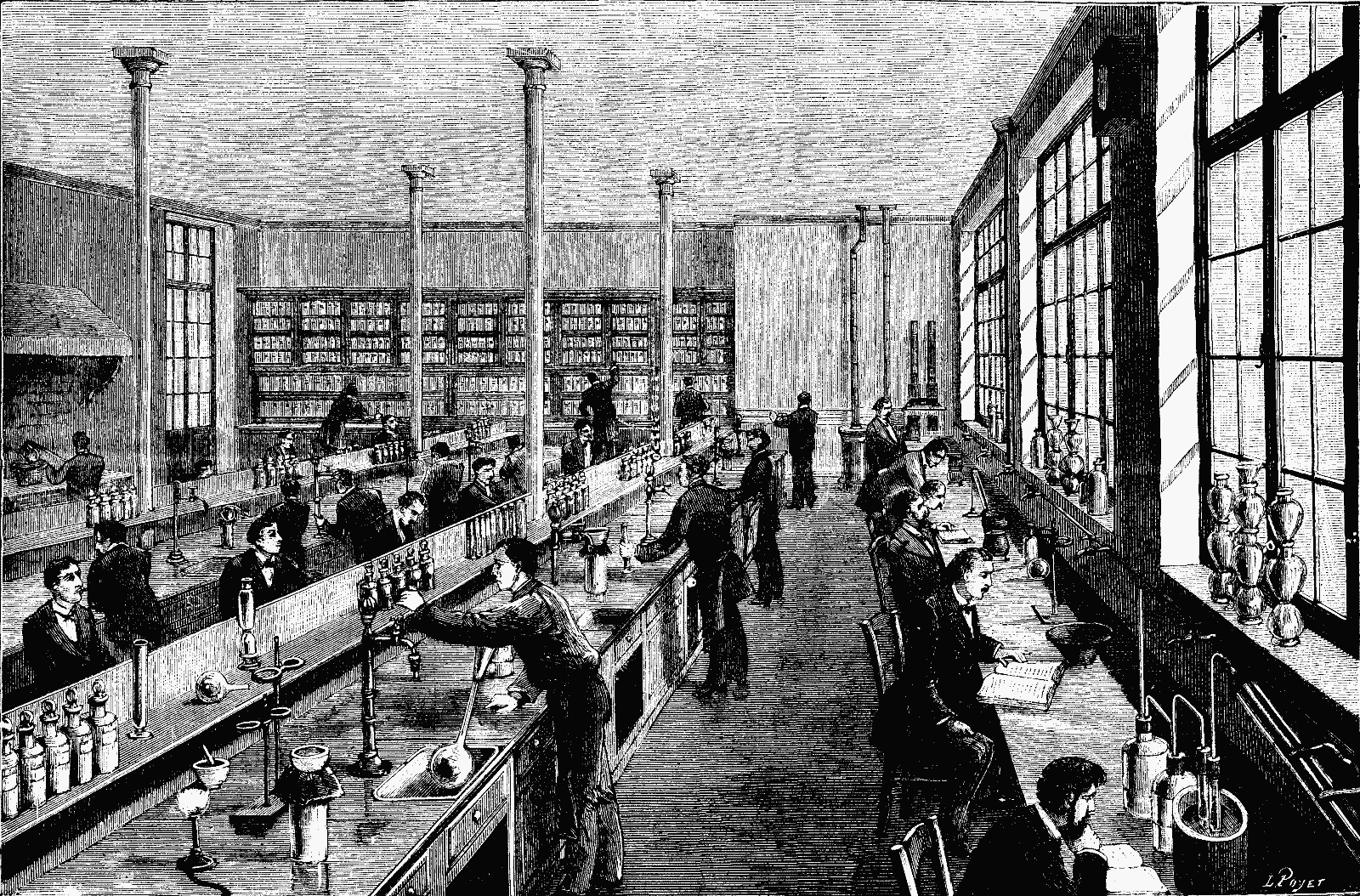
GENERAL VIEW OF A LABORATORY AT THE PARIS SCHOOL OF PHYSICS AND CHEMISTRY.
The pupils occupy themselves regularly every day, during half the time spent at the school, with practical work in analytical and applied chemistry and physics and general chemistry. This practical work is a complement to the various lectures, and has reference to what has been taught therein. Once or twice per week the pupils spend three hours in a shop devoted to wood and metal working, and learn how to turn, forge, file, adjust, etc.
The students engage in practical work in analytical, applied chemistry, and general chemistry daily, spending half of their time at school on this. This hands-on experience complements the lectures and relates to the material covered in them. Once or twice a week, the students spend three hours in a workshop focused on wood and metalworking, where they learn skills like turning, forging, filing, and adjusting.
The school's cabinets are now provided with the best instruments for study, and are daily becoming richer therein. The chemical laboratories are none the less remarkably organized. In the accompanying cut we give a view of one of these—the one that is under the direction of Mr. Schultzenberger, professor of chemistry and director of the new school. Each pupil has his own place in front of a large table provided with a stand whereon he may arrange all the products that he has to employ. Beneath the work-table he has at his disposal a closet in which to place his apparatus after he is through using them. Each pupil has in front of him a water-faucet, which is fixed to a vertical column and placed over a sink. Alongside of this faucet there is a double gas burner, which may be connected with furnaces and heating apparatus by means of rubber tubing. A special hall, with draught and ventilation, is set apart for precipitations by sulphureted hydrogen and the preparation of chlorine and other ill-smelling and deleterious gases. The great amount of light and space provided secure the best of conditions of hygiene to this fine and vast laboratory, where young people have all the necessary requisites for becoming true chemists.—La Nature.
The school's cabinets are now equipped with top-notch study tools, and they are getting better every day. The chemical labs are just as well organized. In the accompanying image, we show one of these labs—the one managed by Mr. Schultzenberger, the chemistry professor and head of the new school. Each student has their own spot at a large table fitted with a stand for arranging all the materials they need. Below the worktable, there’s a cabinet for storing their equipment once they’re done using it. Every student has a water faucet in front of them, secured to a vertical column above a sink. Next to this faucet is a double gas burner that can connect to furnaces and heating devices using rubber tubing. A special room, with proper airflow and ventilation, is designated for reactions involving hydrogen sulfide and the preparation of chlorine and other unpleasant and harmful gases. The ample light and space ensure excellent hygiene conditions in this impressive and spacious lab, where young people have everything they need to become real chemists.—La Nature.
DUST-FREE SPACES.1
Within the last few years a singular interest has arisen in the subject of dust, smoke, and fog, and several scientific researches into the nature and properties of these phenomena have been recently conducted. It so happened that at the time I received a request from the secretary of this society to lecture here this afternoon I was in the middle of a research connected with dust, which I had been carrying on for some months in conjunction with Mr. J.W. Clark, Demonstrator of Physics in University College, Liverpool, and which had led us to some interesting results. It struck me that possibly some sort of account of this investigation might not be unacceptable to a learned body such as this, and accordingly I telegraphed off to Mr. Moss the title of this afternoon's lecture. But now that the time has come for me to approach the subject before you, I find myself conscious of some misgivings, and the misgivings are founded upon this ground: that the subject is not one that lends itself easily to experimental demonstration before an audience. Many of the experiments can only be made on a small scale, and require to be watched closely. However, by help of diagrams and by not confining myself too closely to our special investigation, but dealing somewhat with the wider subject of dust in general, I may hope to render myself and my subject intelligible if not very entertaining.
In the last few years, there has been a growing interest in dust, smoke, and fog, and several scientific studies into the nature and properties of these phenomena have been conducted recently. Coincidentally, when I received a request from the secretary of this society to give a lecture this afternoon, I was in the midst of research related to dust that I had been working on for a few months with Mr. J.W. Clark, a Demonstrator of Physics at University College, Liverpool, which led us to some intriguing findings. I thought it might be worthwhile to share some insights from this investigation with a learned group like this, so I texted Mr. Moss the title of today’s lecture. However, now that the time has come to discuss the topic with you, I find myself feeling a bit apprehensive, and this concern stems from the fact that the subject doesn’t easily lend itself to experimental demonstration in front of an audience. Many of the experiments can only be done on a small scale and need careful observation. Nonetheless, with the aid of diagrams and by not sticking too closely to our specific research, but addressing the broader topic of dust in general, I hope to make myself and my subject understandable, if not particularly entertaining.
First of all, I draw no distinction between "dust" and "smoke." It would be possible to draw such a distinction, but it would hardly be in accordance with usage. Dust might be defined as smoke which had settled, and the term smoke applied to solid particles still suspended in the air. But at present the term "smoke" is applied to solid particles produced by combustion only, and "dust" to particles owing their floating existence to some other cause. This is evidently an unessential distinction, and for the present I shall use either term without distinction, meaning by dust or smoke, solid particles floating in the air. Then "fog"; this differs from smoke only in the fact that the particles are liquid instead of solid. And the three terms dust, smoke, and fog, come to much the same thing, only that the latter term is applied when the suspended particles are liquid. I do not think, however, that we usually apply the term "fog" when the liquid particles are pure water; we call it then mostly either mist or cloud. The name "fog," at any rate in towns, carries with it the idea of a hideous, greasy compound, consisting of smoke and mist and sulphur and filth, as unlike the mists on a Highland mountain as a country meadow is unlike a city slum. Nevertheless, the finest cloud or mist that ever existed consists simply of little globules of water suspended in air, and thus for our present purpose differs in no important respect from fog, dust, and smoke. A cloud or mist is, in fact, fine water-dust. Rain is coarse water-dust formed by the aggregation of smaller globules, and varying in fineness from the Scotch mist to the tropical deluge. It has often been asked how it is that clouds and mists are able to float about when water is so much heavier (800 times heavier) than air. The answer to this is easy. It depends on the resistance or viscosity of fluids, and on the smallness of the particles concerned. Bodies falling far through fluids acquire a "terminal velocity," at which they are in stable equilibrium—their weight being exactly equal to the resistance—and this terminal velocity is greater for large particles than for small; consequently we have all sorts of rain velocity, depending on the size of the drops; and large particles of dust settle more quickly than small. Cloud-spherules are falling therefore, but falling very slowly.
First of all, I see no difference between "dust" and "smoke." You could make a distinction, but it wouldn't really align with common usage. Dust could be described as smoke that has settled, while smoke refers to solid particles still hanging in the air. Right now, though, "smoke" is only used for solid particles created by burning, and "dust" is used for particles floating for other reasons. This is clearly an unimportant distinction, so for now, I'll use either term interchangeably, meaning solid particles in the air. Then there's "fog"; it only differs from smoke in that the particles are liquid rather than solid. The three terms—dust, smoke, and fog—are quite similar, with the term fog used when the suspended particles are liquid. However, we usually don't say "fog" when the liquid particles are just pure water; we typically call it mist or cloud then. The term "fog," especially in urban areas, conjures up an image of a nasty, greasy mixture of smoke, mist, sulfur, and grime, vastly different from the mists found on a Highland mountain, much like a country meadow differs from a city slum. Still, the finest cloud or mist consists simply of tiny water droplets suspended in air, making it not significantly different from fog, dust, and smoke for our current discussion. A cloud or mist is essentially fine water-dust. Rain is just heavier water-dust formed by smaller droplets coming together, varying in size from the light Scotch mist to a heavy tropical downpour. People often wonder how clouds and mists can float when water is so much heavier (800 times heavier) than air. The answer is straightforward. It’s all about the resistance or viscosity of fluids and the size of the particles involved. Objects falling through fluids reach a "terminal velocity," where they are in stable equilibrium—their weight perfectly balanced by the resistance—and larger particles have a higher terminal velocity than smaller ones. This is why rain can have different speeds depending on the size of the drops, and larger dust particles settle more quickly than smaller ones. Thus, cloud droplets are falling, but very slowly.
To recognize the presence of dust in air there are two principal tests; the first is, the obvious one of looking at it with plenty of light, the way one is accustomed to look for anything else; the other is a method of Mr. John Aitken's, viz., to observe the condensation of water vapor.
To identify dust in the air, there are two main tests: the first is the straightforward approach of examining it under adequate light, just like you would look for anything else; the second is Mr. John Aitken's method, which involves observing the condensation of water vapor.
Take these in order. When a sunbeam enters a darkened room through a chink, it is commonly said to be rendered visible by the motes or dust particles dancing in it; but of course really it is not the motes which make the sunbeam visible, but the sunbeam the motes. A dust particle is illuminated like any other solid screen, and is able to send a sufficient fraction of light to our eyes to render itself visible. If there are no such particles in the beam—nothing but clear, invisible air—then of course nothing is seen, and the beam plunges on its way quite invisible to us unless we place our eyes in its course. In other words, to be visible, light must enter the eye. (A concentrated beam was passed through an empty tube, and then ordinary air let in.)
Take these in order. When a sunbeam comes into a dark room through a crack, it’s often said that the dust particles floating in the light make it visible. However, the reality is that it’s not the dust that makes the sunbeam visible, but rather the sunbeam that makes the dust visible. A dust particle is lit up like any other solid object and can reflect enough light for us to see it. If there are no particles in the beam—just clear, invisible air—then nothing is visible, and the beam continues on its path completely invisible to us unless we position our eyes in its path. In other words, for light to be seen, it must enter the eye. (A concentrated beam was passed through an empty tube, and then regular air was let in.)
The other test, that of Mr. Aitken, depends on the condensation of steam. When a jet of steam finds itself in dusty air, it condenses around each dust particle as a nucleus, and forms the white visible cloud popularly called steam. In the absence of nuclei Mr. Aitken has shown that the steam cannot condense until it is highly supersaturated, and that when it does it condenses straight into rain—that is, into large drops which fall. The condensation of steam is a more delicate test for dust than is a beam of light. A curious illustration of the action of nuclei in condensing moisture has just occurred to me, in the experiment—well known to children—of writing on a reasonably clean window-pane with, say, a blunt wooden point, and then breathing on the glass; the condensation of the breath renders the writing legible. No doubt the nuclei are partially wiped away by the writing, and the moisture will condense into larger drops with less light-scattering power along the written lines than over the general surface of the pane where the nuclei are plentiful, and the drops therefore numerous and minute. Mr. Aitken points out that if the air were ever quite dustless, vapor could not condense, but the air would gradually get into a horribly supersaturated condition, soaking all our walls and clothes, dripping from every leaf, and penetrating everywhere, instead of falling in an honest shower, against which umbrellas and slate roofs are some protection. But let us understand what sort of dust it is which is necessary for this condensing process. It is not the dust and smoke of towns, it is not the dust of a country road; all such particles as these are gross and large compared with those which are able to act as condensers of moisture. The fine dust of Mr. Aitken exists everywhere, even in the upper regions of the atmosphere; many of its particles are of ultra-microscopic fineness, one of them must exist in every raindrop, nay, even in every spherule of a mist or cloud, but it is only occasionally that one can find them with the microscope. It is to such particles as these that we owe the blue of the sky, and yet they are sufficiently gross and tangible to be capable of being filtered out of the air by a packed mass of cotton-wool. Such dust as this, then, we need never be afraid of being without. Without it there could be no rain, and existence would be insupportable, perhaps impossible; but it is not manufactured in towns; the sea makes it; trees and wind make it; but the kind of dust made in towns rises only a few hundred yards or so into the atmosphere, floating as a canopy or pall over those unfortunate regions, and sinks and settles most of it as soon as the air is quiet, but scarcely any of it ever rises into the upper regions of the atmosphere at all.
The other test, conducted by Mr. Aitken, involves the condensation of steam. When a stream of steam encounters dusty air, it condenses around each dust particle, which acts as a nucleus, creating the visible white cloud commonly known as steam. Mr. Aitken has demonstrated that without these nuclei, steam cannot condense unless it is highly supersaturated, and when it does condense, it turns directly into rain—large drops that fall. The condensation of steam is a more sensitive test for dust than a beam of light. A fascinating example of how nuclei help condense moisture comes to mind: the experiment familiar to children where you write on a clean window with a blunt wooden point and then breathe on the glass; the breath causes condensation that makes the writing visible. The nuclei are likely partially removed by the writing, and the moisture condenses into larger drops along the written lines, which scatter less light compared to the areas of the pane rich in nuclei, where the drops are numerous and tiny. Mr. Aitken points out that if the air were completely dust-free, vapor would not be able to condense, leading to a dangerously supersaturated environment, soaking our walls and clothes, dripping from every leaf, and permeating everywhere, rather than falling as a proper rain shower, against which umbrellas and slate roofs offer some protection. However, let’s clarify what type of dust is required for this condensation process. It isn’t the dust and smoke from cities or the dust from country roads; those particles are too large compared to the ones capable of moisture condensation. The fine dust identified by Mr. Aitken is found everywhere, even in the upper atmosphere; many of its particles are ultra-microscopic, and one particle must exist in every raindrop, or even in every tiny droplet of mist or cloud, although they are only occasionally visible under a microscope. It is these particles that give us the blue sky, yet they are large enough to be filtered out of the air using a tight mass of cotton-wool. Therefore, we need not worry about being without this type of dust. Without it, there could be no rain, making life unbearable, if not impossible; but it isn’t produced in cities; the sea creates it, as do trees and wind. In contrast, the kind of dust generated in cities only rises a few hundred yards into the atmosphere, forming a canopy or blanket over those unfortunate areas, and most of it settles as soon as the air becomes still, hardly any of it ever reaching the upper atmosphere at all.
Dust, then, being so universally prevalent, what do I mean by dust-free spaces? How are such things possible? And where are they to be found? In 1870 Dr. Tyndall was examining dusty air by means of a beam of light in which a spirit-lamp happened to be burning, when he noticed that from the flame there poured up torrents of apparently thick black smoke. He could not think the flame was really smoky, but to make sure he tried, first a Bunsen gas flame and then a hydrogen flame. They all showed the same effect, and smoke was out of the question. He then used a red-hot poker, a platinum wire ignited by an electric current, and ultimately a flask of hot water, and he found that from all warm bodies examined in dusty air by a beam of light the upstreaming convection currents were dark. Now, of course smoke would behave very differently. Dusty air itself is only a kind of smoke, and it looks bright, and the thicker the smoke the brighter it looks; the blackness is simply the utter absence of smoke; there is nothing at all for the light to illuminate, accordingly we have the blankness of sheer invisibility. Here is a flame burning under the beam, and, to show what real smoke looks like, I will burn also this spirit lamp filled with turpentine instead of alcohol. Why the convention currents were free from dust was unknown; Tyndall thought the dust was burnt and consumed; Dr. Frankland thought it was simply evaporated.
Dust is everywhere, so what do I mean by dust-free spaces? How is that even possible? And where can you find them? In 1870, Dr. Tyndall was looking at dusty air using a beam of light, with a spirit lamp burning nearby, when he noticed thick black smoke rising from the flame. He couldn’t believe the flame was actually smoky, so he tested it with a Bunsen gas flame and then a hydrogen flame. They all showed the same thing, and smoke was definitely not the cause. He then tried a red-hot poker, a platinum wire lit by an electric current, and ultimately a flask of hot water. He found that all warm objects in dusty air, when examined with a beam of light, produced dark convection currents. Clearly, smoke would act very differently. Dusty air is sort of like smoke; it appears bright, and the thicker the smoke, the brighter it seems. The blackness indicates a complete lack of smoke; there’s nothing for the light to shine on, leading to total invisibility. Here is a flame burning under the beam, and to show what real smoke looks like, I will also burn this spirit lamp filled with turpentine instead of alcohol. Why the convection currents were free of dust was a mystery; Tyndall thought the dust was burned up, while Dr. Frankland believed it simply evaporated.
In 1881 Lord Rayleigh took the matter up, not feeling satisfied with these explanations, and repeated the experiment very carefully. He noted several new points, and hit on the capital idea of seeing what a cold body did. From the cold body the descending current was just as dark and dust-free as from a warm body. Combustion and evaporation explanations suffered their death-blow. But he was unable to suggest any other explanation in their room, and so the phenomenon remained curious and unexplained.
In 1881, Lord Rayleigh took it upon himself to investigate further, feeling unconvinced by the existing explanations. He carefully repeated the experiment and noted several new points, coming up with the key idea of observing what a cold body did. The descending current from the cold body turned out to be just as dark and free of dust as that from a warm body. This effectively disproved the theories of combustion and evaporation. However, he couldn't propose any alternative explanation, leaving the phenomenon still puzzling and unexplained.
In this state Mr. Clark and I took the matter up last summer, and critically examined all sorts of hypotheses that suggested themselves, Mr. Clark following up the phenomena experimentally with great ingenuity and perseverance. One hypothesis after another suggested itself, seemed hopeful for a time, but ultimately had to be discarded. Some died quickly, others lingered long. In the examination of one electrical hypothesis which suggested itself we came across various curious phenomena which we hope still to follow up.2 It was some months before what we now believe to be the true explanation began to dawn upon us. Meanwhile we had acquired various new facts, and first and foremost we found that the dark plane rising from a warm body was only the upstreaming portion of a dust-free coat perpetually being renewed on the surface of the body. Let me describe the appearance and mode of seeing it by help of a diagram. (For full description see Philosophical Magazine for March, 1884.)
Last summer, Mr. Clark and I took up the issue and carefully explored all kinds of theories that came to mind, with Mr. Clark testing the phenomena with remarkable creativity and determination. One theory after another seemed promising at first but eventually had to be set aside. Some faded quickly, while others stuck around longer. While investigating one electrical theory, we encountered several interesting phenomena that we hope to explore further. It took us several months to start understanding what we now believe to be the correct explanation. In the meantime, we gathered various new facts, the most important being that the dark plane rising from a warm body was actually just the upper layer of a dust-free coat that is constantly being renewed on the surface of the body. Let me illustrate what it looks like and how we observe it with a diagram. (For full description see Philosophical Magazine for March, 1884.)
Surrounding all bodies warmer than the air is a thin region free from dust, which shows itself as a dark space when examined by looking along a cylinder illuminated transversely, and with a dark background. At high temperatures the coat is thick; at very low temperatures it is absent, and dust then rapidly collects on the rod. On a warm surface only the heavy particles are able to settle—there is evidently some action tending to drive small bodies away. An excess of temperature of a degree or two is sufficient to establish this dust-free coat, and it is easy to see the dust-free plane rising from it. The appearances may also be examined by looking along a cylinder toward the source of light, when the dust-free spaces will appear brighter than the rest. A rod of electric light carbon warmed and fixed horizontally across a bell-jar full of dense smoke is very suitable for this experiment, and by means of a lens the dust-free regions may be thus projected on to a screen. Diminished pressure makes the coat thicker. Increased pressure makes it thinner. In hydrogen it is thicker, and in carbonic acid thinner, than in air. We have also succeeded in observing it in liquids—for instance, in water holding fine rouge in suspension, the solid body being a metal steam tube. Quantitative determinations are now in progress.
Surrounding all objects that are warmer than the air is a thin area without dust, which appears as a dark space when observed through a cylinder lit from the side against a dark background. At high temperatures, this area is thick; at very low temperatures, it disappears, causing dust to quickly settle on the rod. On a warm surface, only heavier particles can settle—there’s clearly something pushing smaller particles away. Even a temperature difference of a degree or two is enough to create this dust-free area, and you can easily see the dust-free layer rising from it. You can also see the effect by looking along a cylinder towards the light source, where the dust-free areas will appear brighter than the rest. A horizontally positioned bar of electric light carbon heated and placed across a bell-jar filled with dense smoke works really well for this experiment, and using a lens, the dust-free regions can be projected onto a screen. Lowering the pressure makes the layer thicker, while increasing the pressure makes it thinner. It’s thicker in hydrogen and thinner in carbon dioxide compared to air. We've also managed to observe it in liquids—for example, in water with fine rouge suspended, with the solid object being a metal steam tube. We're currently working on quantitative measurements.
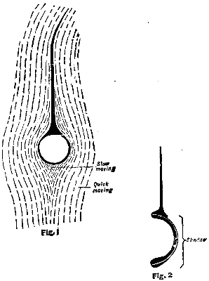
Fig. 1 shows the appearance when looking along a copper or carbon rod laterally illuminated; the paths of the dust particles are roughly indicated. Fig. 2 shows the coat on a semi-cylinder of sheet copper with the concave side turned toward the light.
Fig. 1 shows how it looks when you look along a copper or carbon rod that’s lit from the side; the paths of the dust particles are roughly marked. Fig. 2 shows the coating on a semi-cylinder of sheet copper with the curved side facing the light.
It is difficult to give the full explanation of the dust free spaces in a few words, but we may say roughly that there is a molecular bombardment from all warm surfaces by means of which small suspended bodies get driven outward and kept away from the surface. It is a sort of differential bombardment of the gas molecules on the two faces of a dust particle somewhat analogous to the action on Mr. Crookes' radiometer vanes. Near cold surfaces the bombardment is very feeble, and if they are cold enough it appears to act toward the body, driving the dust inward—at any rate, there is no outward bombardment sufficient to keep the dust away, and bodies colder than the atmosphere surrounding them soon get dusty. Thus if I hold this piece of glass in a magnesium flame, or in a turpentine or camphor flame, it quickly gets covered with smoke—white in the one case, black in the other. I take two conical flasks with their surfaces blackened with camphor black, and filling one with ice, the other with boiling water, I cork them and put a bell jar over them, under which I burn some magnesium wire; in a quarter of an hour or so we find that the cold one is white and hoary, the hot one has only a few larger specks of dust on it, these being of such size that the bombardment was unable to sustain their weight, and they have settled by gravitation. We thus see that when the air in a room is warmer than the solids in it—as will be the case when stoves, gas-burners, etc., are used—things will get very dusty; whereas when walls and objects are warmer than the air—as will be the case in sunshine, or when open fireplaces are used, things will tend to keep themselves more free from dust. Mr. Aitken points out that soot in a chimney is an illustration of this kind of deposition of dust; and as another illustration it strikes me as just possible that the dirtiness of snow during a thaw may be partly due to the bombardment on to the cold surface of dust out of the warmer air above. Mr. Aitken has indeed suggested a sort of practical dust or smoke filter on this principle, passing air between two surfaces—one hot and one cold—so as to vigorously bombard the particles on to the cold surface and leave the air free.
It’s tough to fully explain dust-free areas in just a few words, but roughly speaking, it involves molecular bombardment from all warm surfaces, which pushes small suspended particles outward and keeps them away from surfaces. This is like a differential bombardment of gas molecules acting on both sides of a dust particle, somewhat similar to what happens with Mr. Crookes' radiometer vanes. Near cold surfaces, the bombardment is very weak, and if the surfaces are cold enough, it seems to attract particles, pulling dust inward—at least, the outward bombardment isn't strong enough to keep the dust away, and things that are colder than the surrounding atmosphere will quickly gather dust. For example, if I hold this piece of glass in a magnesium flame or in a turpentine or camphor flame, it quickly becomes covered with smoke—white in one case, black in the other. I take two conical flasks, blackening their surfaces with camphor black, and fill one with ice and the other with boiling water. I cork them, then place a bell jar over them and burn some magnesium wire underneath. After about fifteen minutes, we find that the cold flask is covered in a white frost while the hot one has only a few larger dust specks, too heavy for the bombardment to keep afloat, which have settled due to gravity. This shows that when the air in a room is warmer than the solid objects in it—like when stoves or gas burners are used—things become quite dusty. However, when the walls and objects are warmer than the air—like when they're in sunlight or near open fireplaces—they tend to stay cleaner. Mr. Aitken notes that soot accumulating in a chimney is an example of this dust deposition; another possible example might be that the dirtiness of snow during a thaw could be partially because dust from warmer air settles onto the cold surface. Mr. Aitken has even proposed a kind of practical dust or smoke filter based on this principle, where air passes between two surfaces—one hot and the other cold—causing particles to be forcibly pushed onto the cold surface, keeping the air clear.
But we have found another and apparently much more effectual mode of clearing air than this. We do it by discharging electricity into it. It is easily possible to electrify air by means of a point or flame, and an electrified body has this curious property, that the dust near it at once aggregates together into larger particles. It is not difficult to understand why this happens; each of the particles becomes polarized by induction, and they then cling together end to end, just like iron filings near a magnet. A feeble charge is often sufficient to start this coagulating action. And when the particles have grown into big ones, they easily and quickly fall. A stronger charge forcibly drives them on to all electrified surfaces, where they cling. A fine water fog in a bell jar, electrified, turns first into a coarse fog or Scotch mist, and then into rain. Smoke also has its particles coagulated, and a space can thus be cleared of it. I will illustrate this action by making some artificial fogs in a bell-jar furnished with a metal point. First burn some magnesium wire, electrify it by a few turns of this small Voss machine, and the smoke has become snow; the particles are elongated, and by pointing to the charged rod indicate the lines of electrostatic force very beautifully; electrify further, and the air is perfectly clear. Next burn turpentine, and electrify gently; the dense black smoke coagulates into black masses over an inch long; electrify further, and the glass is covered with soot, but the air is clear. Turpentine smoke acts very well, and can be tried on a larger scale; a room filled with turpentine smoke, so dense that a gas-light is invisible inside it, begins to clear in a minute or two after the machine begins to turn, and in a quarter of an hour one can go in and find the walls thickly covered with stringy blacks, notably on the gas-pipes and everything most easily charged by induction. Next fill a bell-jar full of steam, and electrify, paying attention to insulation of the supply point in this case. In a few seconds the air looks clear, and turning on a beam of light we see the globules of water dancing about, no longer fine and impalpable, but separately visible and rapidly falling. Finally, make a London fog by burning turpentine and sulphur, adding a little sulphuric acid, either directly as vapor or indirectly by a trace of nitric oxide, and then blowing in steam. Electrify, and it soon becomes clear, although it lakes a little longer than before; and on removing the bell-jar we find that even the smell of SO2 has disappeared, and only a little vapor of turpentine remains. Similarly we can make a Widnes fog by sulphureted hydrogen, chlorine, sulphuric acid, and a little steam. Probably the steam assists the clearing when gases have to be dealt with. It may be possible to clear the air of tunnels by simply discharging electricity into the air—the electricity being supplied by Holtz machines, driven say by small turbines—a very handy form of power, difficult to get out of order. Or possibly some hydro-electric arrangement might be devised for the locomotive steam to do the work. I even hope to make some impression on a London fog, discharging from lightning conductors or captive balloons carrying flames, but it is premature to say anything about this matter yet. I have, however, cleared a room of smoke very quickly with a small hand machine.
But we've discovered another, seemingly more effective way to clear the air than this. We do it by discharging electricity into it. It's quite easy to electrify air using a point or flame, and an electrified object has this interesting ability: the dust around it immediately clumps together into larger particles. It's not hard to see why this happens; each of the particles becomes polarized through induction, and then they stick together end to end, just like iron filings around a magnet. Even a small charge is often enough to trigger this clumping action. Once the particles grow into larger ones, they fall easily and quickly. A stronger charge pushes them toward all electrified surfaces, where they stick. A fine mist in a bell jar, when electrified, first becomes a thick fog or Scotch mist, and then it turns into rain. Smoke also clumps its particles together, allowing a space to be cleared of it. I'll demonstrate this action by creating some artificial fogs in a bell jar equipped with a metal point. First, burn some magnesium wire and electrify it with a few turns of this small Voss machine, and the smoke will turn into snow; the particles will stretch out, and by directing it at the charged rod, we can beautifully show the lines of electrostatic force; if we electrify it more, the air becomes perfectly clear. Next, burn turpentine and apply a light electrification; the thick black smoke clusters into black lumps over an inch long; if we electrify it further, the glass gets covered with soot, but the air remains clear. Turpentine smoke works really well and can be tested on a larger scale; a room filled with turpentine smoke so dense that the gas light inside it is invisible starts to clear up in a minute or two after the machine is switched on, and within a quarter of an hour, you can go in and find the walls heavily coated with stringy black particles, particularly on the gas pipes and anything that is easily charged by induction. Then, fill a bell jar full of steam and electrify it, being careful with the insulation at the supply point here. In just a few seconds, the air looks clear, and if we shine a beam of light, we can see the water droplets moving around, no longer tiny and indistinct, but individually visible and rapidly falling. Finally, create a London fog by burning turpentine and sulfur, adding a bit of sulfuric acid, either directly as vapor or indirectly through a trace of nitric oxide, and then blowing in steam. Electrify it, and it clears up soon, although it takes a little longer than before; when we remove the bell jar, we discover that even the smell of SO2 has vanished, and only a slight vapor of turpentine remains. Similarly, we can make a Widnes fog using hydrogen sulfide, chlorine, sulfuric acid, and a bit of steam. The steam probably helps clear the air when dealing with gases. It might be possible to clear the air in tunnels by simply discharging electricity into it—the electricity supplied by Holtz machines, powered by small turbines, which are a very convenient power source that’s hard to malfunction. Alternatively, some hydro-electric setup could be created to harness locomotive steam for this purpose. I even hope to have an effect on a London fog using lightning conductors or captive balloons carrying flames, but it's too early to say anything definitive about that yet. However, I have quickly cleared a room of smoke using a small hand machine.
It will naturally strike you how closely allied these phenomena must be to the fact of popular science that "thunder clears the air." Ozone is undoubtedly generated by the flashes, and may have a beneficial effect, but the dust-coagulating and dust-expelling power of the electricity has a much more rapid effect, though it may not act till the cloud is discharged. Consider a cloud electrified slightly; the mists and clouds in its vicinity begin to coagulate, and go on till large drops are formed, which may be held up by electrical action, the drops dancing from one cloud to another and thus forming the very dense thunder cloud. The coagulation of charged drops increases the potential, as Prof. Tait points out, until at length—flash—the cloud is discharged, and the large drops fall in a violent shower. Moreover, the rapid excursion to and fro of the drops may easily have caused them to evaporate so fast as to freeze, and hence we may get hail.
It will naturally occur to you how closely related these phenomena are to the popular science fact that "thunder clears the air." Ozone is definitely produced by the lightning, and it may have a positive effect, but the electricity's ability to clump together and push out dust has a much quicker impact, even if it doesn't take action until the cloud is discharged. Think about a slightly electrified cloud; the mists and nearby clouds start to clump together, continuing until large droplets form, which can be held up by electrical forces. These droplets move from one cloud to another, creating a very dense thundercloud. The clumping of charged droplets increases the potential, as Prof. Tait points out, until finally—flash—the cloud discharges, and the large droplets fall in a heavy downpour. Additionally, the rapid movement of the droplets back and forth may have caused them to evaporate so quickly that they freeze, leading to hail.
While the cloud was electrified, it acted inductively on the earth underneath, drawing up an opposite charge from all points, and thus electrifying the atmosphere. When the discharge occurs this atmospheric electrification engages with the earth, clearing the air between, and driving the dust and germs on to all exposed surfaces. In some such way also it may be that "thunder turns milk sour," and exerts other putrefactive influences on the bodies which receive the germs and dust from the air.
While the cloud was charged with electricity, it induced a reaction in the ground below, pulling up an opposite charge from all directions and thereby electrifying the air. When the discharge happens, this charged atmosphere interacts with the earth, clearing the air in between and pushing dust and germs onto all exposed surfaces. In this way, it may also be true that "thunder turns milk sour" and has other spoiling effects on the bodies that come into contact with the germs and dust from the air.
But we are now no longer on safe and thoroughly explored territory. I have allowed myself to found upon a basis of experimental fact, a superstructure of practical application to the explanation of the phenomena of nature and to the uses of man. The basis seems to me strong enough to bear most of the superstructure, but before being sure it will be necessary actually to put the methods into operation and to experiment on a very large scale. I hope to do this when I can get to a suitable place of operation. Liverpool fogs are poor affairs, and not worth clearing off. Manchester fogs are much better and more frequent, but there is nothing to beat the real article as found in London, and in London if possible I intend to rig up some large machines and to see what happens. The underground railway also offers its suffocating murkiness as a most tempting field for experiment, and I wish I were able already to tell you the actual result instead of being only in a position to indicate possibilities. Whether anything comes of it practically or not, it is an instructive example of how the smallest and most unpromising beginnings may, if only followed up long enough, lead to suggestions for large practical application. When we began the investigation into the dust-free spaces found above warm bodies, we were not only without expectation, but without hope or idea of any sort, that anything was likely to come of it; the phenomenon itself possessed its own interest and charm.
But we're no longer on safe, well-explored ground. I've allowed myself to build on a foundation of experimental facts, creating a structure for practical applications to explain natural phenomena and their usefulness to humans. This foundation seems strong enough to support most of the structure, but before I can be sure, I'll need to actually put the methods into practice and conduct large-scale experiments. I hope to do this when I find the right place to work. The fog in Liverpool is unimpressive and not worth clearing away. The fog in Manchester is much better and more frequent, but nothing compares to the real deal in London. If possible, I plan to set up some large machines there and see what happens. The underground railway also has its thick, suffocating fog, which presents a tempting opportunity for experimentation. I wish I could already share the actual results instead of just hinting at possibilities. Regardless of whether anything practical comes from it, it's a valuable example of how the smallest and least promising beginnings can, if pursued long enough, lead to ideas for significant practical applications. When we started investigating the dust-free spaces found above warm bodies, we had no expectations, hope, or ideas that anything would likely come of it; the phenomenon itself was intriguing and captivating.
And so it must ever be. The devotee of pure science never has practical developments as his primary aim; often he not only does not know, but does not in the least care whether his researches will ever lead to any beneficial result. In some minds this passive ignoring of the practical goes so far as to become active repulsion; so that some singularly biased minds will not engage in anything which seems likely to lead to practical use. I regard this as an error, and as the sign of a warped judgment, for after all man is to us the most important part of nature; but the system works well nevertheless, and the division of labor accomplishes its object. One man investigates nature impelled simply by his own genius, and because he feels he cannot help it; it never occurs to him to give a reason for or to justify his pursuits. Another subsequently utilizes his results, and applies them to the benefit of the race. Meanwhile, however, it may happen that the yet unapplied and unfruitful results evoke a sneer, and the question: "Cui bono?" the only answer to which question seems to be: "No one is wise enough to tell beforehand what gigantic developments may not spring from the most insignificant fact."
And so it will always be. The person dedicated to pure science isn’t primarily focused on practical outcomes; often, they not only don’t know but also don’t really care if their research ever leads to any useful results. In some instances, this passive disregard for practicality can turn into an active aversion, causing some uniquely narrow-minded individuals to avoid anything that seems likely to have practical applications. I see this as a mistake and a sign of flawed judgment because, after all, humans are the most significant part of nature to us. However, the system works well regardless, and the division of labor achieves its goals. One person explores nature purely driven by their genius and feels compelled to do so; it never even occurs to them to explain or justify their pursuits. Another person later takes their findings and uses them for the greater good. In the meantime, it might happen that the yet unused and unproductive results earn scorn, accompanied by the question: "What's the benefit?"—to which the only answer seems to be: "No one is wise enough to predict what incredible developments might emerge from the tiniest detail."
Lecture to the Royal Dublin Society by Dr. Oliver J. Lodge, April 2, 1884.
Lecture to the Royal Dublin Society by Dr. Oliver J. Lodge, April 2, 1884.
For instance, the electric properties of crystals can be readily examined in illuminated dusty air; the dust grows on them in little bushes and marks out their poles and neutral regions, without any need for an electrometer. Magnesia smoke answers capitally.
For example, the electrical properties of crystals can easily be observed in lit dusty air; the dust forms small clusters and highlights their poles and neutral areas, without needing an electrometer. Magnesia smoke works really well for this.
TELEPHONY AND TELEGRAPHY ON THE SAME WIRES SIMULTANEOUSLY.
For the last eighteen months a system has been in active operation in Belgium whereby the ordinary telegraph wires are used to convey telephonic communications at the same time that they are being employed in their ordinary work of transmitting telegraphic messages. This system, the invention of M. Van Rysselberghe, whose previous devices for diminishing the evil effects of induction in the telephone service will be remembered, has lately been described in the Journal Telegraphique of Berne, by M.J. Banneux of the Belgian Telegraph Department. Our information is derived from this article and from others by M. Hospitalier.
For the past eighteen months, a system has been actively in use in Belgium that allows regular telegraph wires to carry phone communications while still managing their usual job of sending telegraphic messages. This system, created by M. Van Rysselberghe, who is known for his earlier innovations to reduce the negative effects of induction in telephone services, was recently detailed in the Journal Telegraphique of Berne, by M.J. Banneux from the Belgian Telegraph Department. Our information comes from this article and others by M. Hospitalier.
The method previously adopted by Van Rysselberghe, to prevent induction from taking place between the telegraph wires and those running parallel to them used for telephone work, was briefly as follows: The system of sending the dots and dashes of the code—usually done by depressing and raising a key which suddenly turns on the current and then suddenly turns it off—was modified so that the current should rise gradually and fall gradually in its strength by the introduction of suitable resistances. These were introduced into the circuit at the moment of closing or opening by a simple automatic arrangement worked exactly as before by a key. The result, of the gradual opening and gradual closing of the circuit was that the current attained its full strength gradually instead of suddenly, and died away also gradually. And as induction from one wire to another depends not on the strength of the current, but on the rate at which the strength changes, this very simple modification had the effect of suppressing induction. Later Van Rysselberghe changed these arrangements for the still simpler device of introducing permanently into the circuit either condensers or else electro-magnets having a high coefficient of self-induction. These, as is well known to all telegraphic engineers, retard the rise or fall of an electric current; they fulfill the conditions required for the working of Van Rysselberghe's method better than any other device.
The method previously used by Van Rysselberghe to prevent interference between the telegraph wires and the parallel telephone wires was straightforward: The system for sending the dots and dashes of the code—done by pressing and releasing a key that quickly turns the current on and off—was adjusted so that the current would increase and decrease gradually. This was achieved by adding suitable resistances into the circuit at the moment of closing or opening, controlled by a simple automatic setup that still operated with the key. The result of gradually opening and closing the circuit was that the current built up to full strength gradually instead of suddenly, and also faded away gradually. Since interference between wires depends not on the current's strength but on the speed of its change, this simple change effectively eliminated interference. Later, Van Rysselberghe simplified this setup even further by permanently introducing either capacitors or electro-magnets with a high self-induction coefficient into the circuit. As all telegraphic engineers know, these components slow down the rise or fall of an electric current; they better meet the requirements of Van Rysselberghe's method than any other device.
Having got thus far in his devices for destroying induction from one line to another, Van Rysselberghe saw that, as an immediate consequence, it might be concluded that, if the telegraph currents were thus modified and graduated so that they produced no induction in a neighboring telephone line, they would produce no sound in the telephone if that instrument were itself joined up in the telegraph line. And such was found to be case. Why this is so will be more readily comprehended if it be remembered that a telephone is sensitive to the changes in the strength of the current if those changes occur with a frequency of some hundreds or in some cases thousands of times per second. On the other hand, currents vibrating with such rapidity as this are utterly incompetent to affect the moving parts of telegraphic instruments, which cannot at the most be worked so as to give more than 200 to 800 separate signals per minute.
Having made progress in his methods for eliminating induction between wires, Van Rysselberghe realized that it could be concluded that if the telegraph currents were adjusted so they didn't cause induction in a nearby telephone line, they wouldn't produce any sound in the telephone if that device was connected to the telegraph line. And that was indeed the case. Understanding why this happens is easier if we remember that a telephone is sensitive to changes in current strength when those changes happen at frequencies of hundreds or even thousands of times per second. In contrast, currents oscillating at that speed are completely unable to affect the moving parts of telegraphic instruments, which can handle no more than 200 to 800 separate signals per minute.
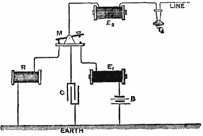
Fig. 1
The simplest arrangement for carrying out this method is shown in Fig.
1, which illustrates the arrangements at one end of a line. M is the
Morse key for sending messages, and is shown as in its position of
rest for receiving. The currents arriving from the line pass first
through a "graduating" electromagnet, E2, of about 500 ohms
resistance, then through the key, thence through the electromagnet, R,
of the receiving Morse instrument, and so to the earth. A condenser,
C, of 2 microfarads capacity is also introduced between the key and
earth. There is a second "graduating" electromagnet, E1, of 500
ohms resistance introduced between the sending battery, B, and the
key. When the key, M, is depressed in order to send a signal, the
current from the battery must charge the condenser, C, and must
magnetize the cores of the two electromagnets, E1 and E2, and is
thereby retarded in rising to its full strength. Consequently no sound
is heard in a telephone, T, inserted in the line-circuit. Neither the
currents which start from one end nor those which start from the other
will affect the telephones inserted in the line. And, if these
currents do not affect telephones in the actual line, it is clear that
they will not affect telephones in neighboring lines. Also the
telephones so inserted in the main line might be used for speaking to
one another, though the arrangement of the telephones in the same
actual line would be inconvenient. Accordingly M. Van Rysselberghe has
devised a further modification in which a separate branch taken from
the telegraph line is made available for the telephone service. To
understand this matter, one other fact must be explained. Telephonic
conversation can be carried on, even though the actual metallic
communication be severed by the insertion of a condenser. Indeed, in
quite the early days of the Bell telephone, an operator in the States
used a condenser in the telegraph line to enable him to talk through
the wire. If a telephonic set at T1 (Fig. 2) communicate through
the line to a distant station, T2, through a condenser, C, of a
capacity of half a microfarad, conversation is still perfectly
audible, provided the telephonic system is one that acts by induction
currents. And since in this case the interposition of the condenser
prevents any continuous flow of current through the line, no
perceptible weakening will be felt if a shunt S, of as high a
resistance as 500 ohms and of great electromagnetic rigidity, that is
to say, having a high coefficient of self-induction, be placed across
the circuit from line to earth. In this, as well as in the other
figures, the telephones indicated are of the Bell pattern, and if set
up as shown in Fig. 2, without any battery, would be used both as
transmitter and receiver on Bell's original plan.
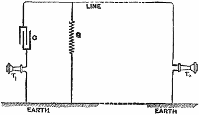
Fig. 2
But as a matter of fact any ordinary telephone might be used. In practice the Bell
telephone is not advantageous as a transmitter, and has been abandoned
except for receiving; the Blake, Ader, or some other modification of
the microphone being used in conjunction with a separate battery. To
avoid complication in the drawings, however, the simplest case is
taken. And it must be understood that instead of the single instrument
shown at T1 or T2, a complete set of telephonic instruments,
including transmitter, battery, induction-coil, and receiver or
receivers, may be substituted. And if a shunt, S, of 500 ohms placed
across the circuit makes no difference to the talking in the
telephones because of the interposition of the separating condenser,
C, it will readily be understood that a telegraphic system properly
"graduated," and having also a resistance of 500 ohms, will not affect
the telephones if interposed in the place of S. This arrangement is
shown in Fig. 3, where the "graduated" telegraph-set from Fig. 1 is
intercalated into the telephonic system of Fig. 2, so that both work
simultaneously, but independently, through a single line. The combined
system at each end of the line will then consist of the telephone-set,
T1, the telegraph instruments (comprising battery, B1, key,
M1 and Morse receiver, R1), the "graduating" electromagnets,
E1, and E2, the "graduating" condenser, C1, and the
"separating" condenser, C2. It was found by actual experiments that
the same arrangement was good for lines varying from 28 to 200 miles
in length. A single wire between Brussels, Ghent, and Ostend is now
regularly employed for transmission by telegraph of the ordinary
messages and of the telemeteorographic signals between the two
observatories at those places, and by telephone of verbal simultaneous
correspondence, for one of the Ghent newspapers. A still more
interesting arrangement is possible, and is indicated in Fig. 4. Here
a separating condenser is introduced at the intermediate station at
Ghent between earth and the line, which is thereby cut into two
independent sections for telephonic purposes, while remaining for
telegraphic purposes a single undivided line between Brussels and
Ostend. Brussels can telegraph to Ostend, or Ostend to Brussels, and
at the same time the wire can be used to telephone between Ghent and
Ostend, or between Ghent and Brussels, or both sections may be
simultaneously used.
The simplest setup for this method is shown in Fig. 1, which illustrates the configurations at one end of a line. M is the Morse key used for sending messages, and it’s shown in its resting position for receiving. The currents coming from the line first pass through a "graduating" electromagnet, E2, with about 500 ohms resistance, then through the key, and on to the electromagnet, R, of the receiving Morse instrument, and finally to the earth. A condenser, C, with a capacity of 2 microfarads is also placed between the key and the earth. There’s a second "graduating" electromagnet, E1, also 500 ohms resistance, placed between the sending battery, B, and the key. When the key, M, is pressed to send a signal, the current from the battery charges the condenser, C, and magnetizes the cores of both electromagnets, E1 and E2, thereby delaying the rise to full strength. As a result, no sound is heard in a telephone, T, connected in the line circuit. Currents starting from either end won’t affect the telephones in the line, and if they don’t affect phones in the actual line, they certainly won’t affect phones in neighboring lines. Additionally, the telephones connected in the main line could be used to speak to each other, although it would be awkward to do so within the same line. Therefore, M. Van Rysselberghe developed another modification where a separate branch from the telegraph line is used for telephone service. To clarify this, one more fact needs to be explained. Telephone conversations can still happen even if the actual metallic connection is interrupted by a condenser. In fact, in the early days of the Bell telephone, an operator in the U.S. used a condenser in the telegraph line to enable communication. If a telephone set at T1 (Fig. 2) communicates through the line to a distant station, T2, via a condenser, C, with a capacity of half a microfarad, the conversation remains perfectly audible, as long as the telephonic system uses induction currents. And since the condenser prevents any continuous current flow through the line, there won't be any noticeable weakening if a shunt S, with 500 ohms resistance and high electromagnetic rigidity, meaning it has a high self-induction coefficient, is placed across the circuit from line to earth. In this case, and in the other figures, the telephones are of the Bell model, and if set up as shown in Fig. 2, without any battery, would function as both transmitter and receiver based on Bell's original design.
Fig. 2
However, in reality, any regular telephone could be used. In practice, the Bell telephone is not effective as a transmitter and is only used for receiving; devices like the Blake, Ader, or other microphone variations are typically used in combination with a separate battery. To keep the drawings straightforward, the simplest scenario is presented. It's important to note that instead of the single instruments shown at T1 or T2, a complete set of telephonic instruments, including the transmitter, battery, induction coil, and receiver(s), could be swapped in. If a shunt, S, of 500 ohms across the circuit doesn’t affect the communication in the telephones due to the condenser, C, it’s easy to understand that a properly "graduated" telegraphic system with a 500-ohm resistance will also not affect the telephones if placed where S is. This setup is depicted in Fig. 3, where the "graduated" telegraph set from Fig. 1 is incorporated into the telephonic system from Fig. 2, allowing both to operate simultaneously but independently through a single line. The overall system at each end will then include the telephone set, T1, the telegraph instruments (comprising battery, B1, key, M1, and Morse receiver, R1), the "graduating" electromagnets, E1 and E2, the "graduating" condenser, C1, and the "separating" condenser, C2. Actual experiments confirmed that this arrangement works well for lines ranging from 28 to 200 miles in length. A single wire connecting Brussels, Ghent, and Ostend is now regularly used for transmitting ordinary telegraph messages and telemeteorographic signals between the two observatories in those locations, as well as for telephone conversations for one of the Ghent newspapers. An even more interesting setup is shown in Fig. 4. Here, a separating condenser is added at the intermediate station in Ghent between the earth and the line, effectively splitting it into two independent sections for phone communication, while still operating as a single, undivided line for telegraph purposes between Brussels and Ostend. This means Brussels can send telegrams to Ostend or vice versa, while simultaneously using the wire for telephone calls between Ghent and Ostend, or from Ghent to Brussels, or both sections at once.
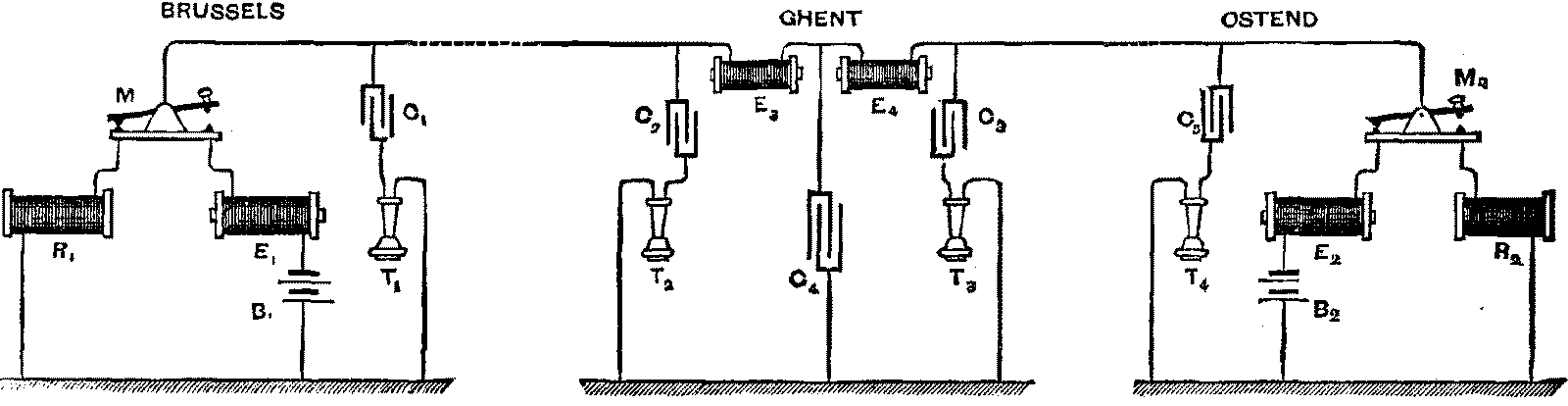
Fig. 3
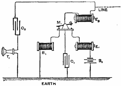
Fig. 4
It would appear, then, that M. Van Rysselberghe has made an advance of very extraordinary merit in devising these combinations. We have seen in recent years how duplex telegraphy superseded single working, only to be in turn superseded by the quadruplex system. Multiplex telegraphy of various kinds has been actively pursued, but chiefly on the other side of the Atlantic rather than in this country, where our fast-speed automatic system has proved quite adequate hitherto. Whether we shall see the adoption in the United Kingdom of Van Rysselberghe's system is, however, by no means certain. The essence of it consists in retarding the telegraphic signals to a degree quite incompatible with the fast-speed automatic transmission of telegraphic messages in which our Post Office system excels. We are not likely to spoil our telegraphic system for the sake of simultaneous telephony, unless there is something to be gained of much greater advantage than as yet appears.—Nature.
It seems that M. Van Rysselberghe has made a remarkable advancement in creating these combinations. In recent years, we've seen how duplex telegraphy replaced single working, only to be replaced by the quadruplex system. Different types of multiplex telegraphy have been actively explored, mainly on the other side of the Atlantic rather than here, where our fast-speed automatic system has been quite effective so far. However, it's uncertain whether Van Rysselberghe's system will be adopted in the United Kingdom. The core of it involves slowing down telegraphic signals to a level that clashes with the fast-speed automatic transmission of telegraphic messages that our Post Office system excels at. We’re unlikely to compromise our telegraphic system for the sake of simultaneous telephony unless there are significant benefits that haven’t been recognized yet.—Nature.
THE ELECTRIC MARIGRAPH.
For registering the height of the tide at every instant, hydrographic services generally adopt quite a simple marigraph. The apparatus consists in principle of a counterpoised float whose rising and falling motion, reduced to a tenth, by means of a system of toothed wheels, is transmitted to a pencil which moves in front of a vertical cylinder. This cylinder itself moves around its axis by means of a clockwork mechanism, and accomplishes one entire revolution every twenty-four hours. By this means is obtained a curve of the tide in which the times are taken for abscisses and the heights of the sea for ordinates. However little such marigraphs have had to be used, great defects have been recognized in them. When we come to change the sheet on the cylinder (and such change should be made at least once every fifteen days), there is an interruption in the curve. It is necessary, besides, to perform office work of the most detailed kind in order to refer to the same origin all these curves, which are intercrossed and often superposed in certain parts upon the original sheet. In order to render such a disentanglement possible, it is indispensable to mark by hand, at least once every twenty-four hours, upon each curve, the date of the day corresponding to it. It is equally useful to verify the exactness of the indications given by the apparatus by making readings several times a day on a scale of tides placed alongside of the float. Nine times out of ten the rise of the waves renders such readings very difficult and the control absolutely illusory.
For tracking the tide’s height at any given moment, hydrographic services typically use a simple tide gauge. This device essentially consists of a counterbalanced float whose rising and falling movement, scaled down by a system of gears, is transferred to a pencil that traces a path on a vertical cylinder. This cylinder rotates around its axis with a clockwork mechanism, completing a full revolution every twenty-four hours. This setup creates a tide curve with time plotted on the horizontal axis and sea heights on the vertical axis. Despite the limited use of such tide gauges, significant flaws have been identified. When it's time to replace the sheet on the cylinder (which should happen at least every fortnight), it causes a break in the curve. Additionally, it's necessary to do detailed administrative work to ensure all these curves share the same starting point, as they intersect and often overlap on the original sheet. To make this sorting feasible, it's crucial to manually note the date on each curve at least once every twenty-four hours. It’s also beneficial to check the accuracy of the readings from the device by taking measurements multiple times a day using a tide scale next to the float. However, nine times out of ten, the wave action makes these readings quite challenging, rendering the verification process practically meaningless.
All these conditions united, as well as others that we neglect in this brief discussion, necessitate a surveillance at every instant. The result is that these marigraphs must be installed in a special structure, very near the bank, so as to be reachable at all times, and that the indications that they give are always vitiated by error, since the operation is performed upon a level at which are exerted disturbing influences that are not found at a kilometer at sea. It were to be desired that the float could be isolated by placing it a certain distance from the shore, and transmit its indications, by meant of a play of currents, to a registering apparatus situated upon terra firma.
All these conditions, along with others that we overlook in this brief discussion, require constant monitoring. Therefore, these tide gauges need to be set up in a special structure very close to the shore, making them accessible at all times. However, the readings they provide are always affected by errors since the measurements are taken at a level where there are disruptive influences not present a kilometer out at sea. Ideally, the float could be isolated by placing it a certain distance from the shore and transmitting its readings, through the movement of currents, to a recording device located on solid ground.
In the course of one of his lectures published in the December number (1883) of the Elektrotechnische Zeitschrift, Mr. Von Hefner-Alteneck tells us that such a desideratum has been supplied by the firm of Siemens & Halske. This marigraph, constructed on an order of the German Admiralty, gives the level of the sea every ten minutes with an approximation of 0.12 per cent., and that too for a difference of 8 meters between the highest and lowest sea. The apparatus consists, as we said above, of a float and registering device, connected with each other by means of a cable. This latter is formed of three ordinary conductors covered with gutta percha and surrounded with a leaden sheath, which latter is itself protected against accident by means of a strong covering of iron wire and hemp. The return is effected through the earth. We shall enter into details concerning each of these two apparatus in-succession, by beginning with the float, of which Fig. 1 gives a general view, and Fig. 2 a diagrammatic sketch. The float moves in a cast iron cylinder, having at its lower part a large number of apertures of small diameter, so that the motion of the waves does not perceptibly influence the level of the water in the interior of the cylinder. It is attached to a copper ribbon, B, whose other extremity is fixed to the drum, T. The ribbon winds around the latter in the rising motion of the float, owing to a spiral spring arranged so as to act upon the drum. The tension of this spring goes on increasing in measure as the float descends.
In one of his lectures published in the December issue (1883) of the Elektrotechnische Zeitschrift, Mr. Von Hefner-Alteneck mentions that such a needed device has been provided by the Siemens & Halske company. This marigraph, built on an order from the German Admiralty, measures sea level every ten minutes with an accuracy of 0.12 percent, even for a difference of 8 meters between the highest and lowest sea levels. As mentioned earlier, the device consists of a float and a recording mechanism connected by a cable. This cable is made up of three standard conductors insulated with gutta-percha and encased in a lead sheath, which is further protected by a sturdy layer of iron wire and hemp. The return is done through the ground. We will discuss each of these two devices in detail one after the other, starting with the float, which is illustrated in Fig. 1 as a general view, and Fig. 2 as a diagrammatic sketch. The float operates within a cast iron cylinder, which has many small diameter openings at its bottom, preventing the motion of the waves from significantly affecting the water level inside the cylinder. It is connected to a copper ribbon, B, with the other end attached to the drum, T. The ribbon wraps around the drum as the float rises, driven by a spiral spring designed to act on the drum. The tension of this spring increases as the float descends.
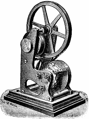
This difference in tension is utilized for balancing at every instant the weight of the ribbon unwound, and thus causing the float to immerse itself in the water to a constant degree. The ribbon, B, is provided throughout its length with equidistant apertures that exactly correspond to tappets that project from the circumference of the wheel, R. When the float moves its position, the wheel, R, begins to turn and carries along in doing so the pinion, w, which revolves over the toothed wheels, s1, s2, and s3. The thickness of w is equal to that of the three wheels, s1, s2, and s3, and a special spring secures at every instant an intimate contact between the pinion and the said wheels. These latter are insulated from each other and from the axle upon which they are keyed, and communicate, each of them, with conductors, I., II., and III. They are so formed and mounted that, in each of them, the tooth in one corresponds to the interspace in the two others. As a result of this, in the motion of the pinion, w, the latter is never in contact with but one of the three wheels, s1, s2, and s3.
This difference in tension is used to constantly balance the weight of the unwound ribbon, keeping the float submerged in the water at a consistent level. The ribbon, B, has evenly spaced openings along its length that match up perfectly with the tappets sticking out from the edge of the wheel, R. When the float changes position, the wheel, R, starts to turn and moves the pinion, w, which rotates over the toothed wheels, s1, s2, and s3. The thickness of w matches that of the three wheels, s1, s2, and s3, and a special spring ensures that there is always close contact between the pinion and these wheels. The wheels are separated from each other and the axle they are attached to, and each one connects to conductors, I., II., and III. They are designed so that in each wheel, the tooth of one aligns with the gap in the other two. Therefore, as the pinion, w, moves, it only makes contact with one of the three wheels, s1, s2, and s3, at a time.
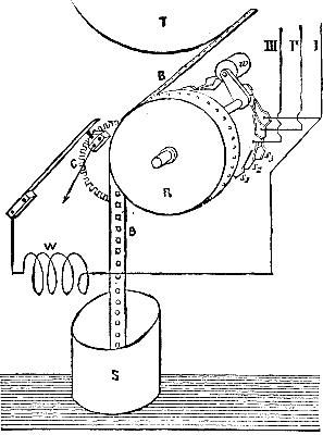
If we add that the lines, I., II., and III. are united at the shore station with one of the poles of a pile whose other pole is connected with the earth, and that w communicates with the earth through the intermedium of R, and the body of the apparatus, it is easy to see that in a vertical motion of the float in one direction we shall have currents succeeding each other in the order I., II., III., I., II., etc., while the order will become III., II., I., III., II., etc., if the direction of the float's motion happen to change.
If we add that lines I, II, and III are connected at the shore station to one of the poles of a pile, with the other pole linked to the ground, and that w connects to the ground through R and the apparatus body, it's clear that when the float moves vertically in one direction, we'll get currents flowing successively in the order of I, II, III, I, II, and so on. If the direction of the float's movement changes, the order will then switch to III, II, I, III, II, etc.
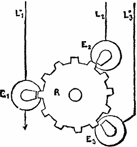

In order to understand how a variation in currents of this kind can be applied in general for producing a rotary motion in the two directions, it will only be necessary to refer to Figs. 3 and 4. The conductors, L1, L2, and L3 communicate with the bobbins of three electromagnets, E1, E2, and E3, whose poles are bent at right angles to the circumference of the wheel, R. There is never but one pole opposite a tooth. The distance between two consecutive poles must be equal to a multiple of the pitch increased (Fig. 3) or diminished (Fig. 4) by one-third thereof. It will be seen upon a simple inspection of the figures that R will revolve in the direction of the hands of a watch when the currents follow the order L1, L2, L3, etc., in the case shown in Fig. 3, while in the case shown in Fig. 4 the rotary motion will be in the contrary direction for this same order of currents. But, in both cases, and this is the important point, the direction of rotation changes when the order in the succession of currents; is inverted. Fig. 6 gives a perspective view of the registering apparatus, and Fig. 5 represents it in diagram. It will be at once seen that, the toothed wheel, r, is reduced to its simplest expression, since it consists of two teeth only. The electro-magnets are arranged at an angle of 120°, and for a change of current the wheel, r, describes an angle of 60°, that is to say, a sixth of a circumference. The motion of r is transmitted, by means of the pinion, d, and the wheel, e, to the wheel, T. For a one-meter variation in level the wheel, T, makes one complete revolution. It is divided into 100 equal parts, and each arc therefore corresponds to a difference of one centimeter in the level, and carries, engraved in projection, the corresponding number. As a consequence, there is upon the entire circumference a series of numbers from to 99. The axle upon which the wheel, T, is keyed is prolonged, on the side opposite e, by a threaded part, a, which actuates a stylet, g. This latter is held above by a rod, I, which is connected with a fork movable around a vertical axis, shown in Fig. 6. The rectilinear motion of g is 5 mm. for a variation of one meter in level. Its total travel is consequently 40 mm. The sheet of paper upon which the indications are taken, and which is shown of actual size in Fig. 7, winds around the drum, P, and receives its motion from the cylinder, W. This sheet is covered throughout its length with fine prepared paper that permits of taking the imprints by impression.
To understand how this type of current variation can generally create rotary motion in both directions, we just need to look at Figs. 3 and 4. The conductors, L1, L2, and L3, connect to the coils of three electromagnets, E1, E2, and E3, whose poles are bent at right angles to the wheel's circumference, R. There is always only one pole opposite a tooth. The distance between two consecutive poles needs to be a multiple of the pitch increased (Fig. 3) or decreased (Fig. 4) by one-third. A simple look at the figures will show that R will turn in the clockwise direction when the currents follow the order L1, L2, L3, etc., as illustrated in Fig. 3, whereas Fig. 4 shows that the rotary motion will be in the opposite direction for the same order of currents. However, in both cases, which is the key point, the rotation direction changes when the order of the currents is reversed. Fig. 6 provides a perspective view of the recording device, while Fig. 5 presents it in diagram form. You can immediately see that the toothed wheel, r, is simplified to its most basic form, having only two teeth. The electromagnets are positioned at a 120° angle, and for a change in current, the wheel, r, moves through an angle of 60°, which is one-sixth of a full circle. The motion of r is transferred through the pinion, d, and the wheel, e, to the wheel, T. For a one-meter change in height, the wheel, T, completes one full revolution. It's divided into 100 equal sections, so each segment corresponds to a one-centimeter difference in height, with the corresponding number engraved. Therefore, there’s a series of numbers from 0 to 99 around the entire circumference. The axle on which the wheel, T, is mounted is extended on the side opposite e with a threaded part, a, which operates a stylus, g. This stylus is held above by a rod, I, connected to a fork that can move around a vertical axis, as shown in Fig. 6. The straight motion of g is 5 mm for a one-meter change in height, resulting in a total travel of 40 mm. The sheet of paper that records the readings, shown at actual size in Fig. 7, wraps around the drum, P, and gets its movement from the cylinder, W. This sheet is coated along its entire length with fine prepared paper that allows for imprinting by pressure.
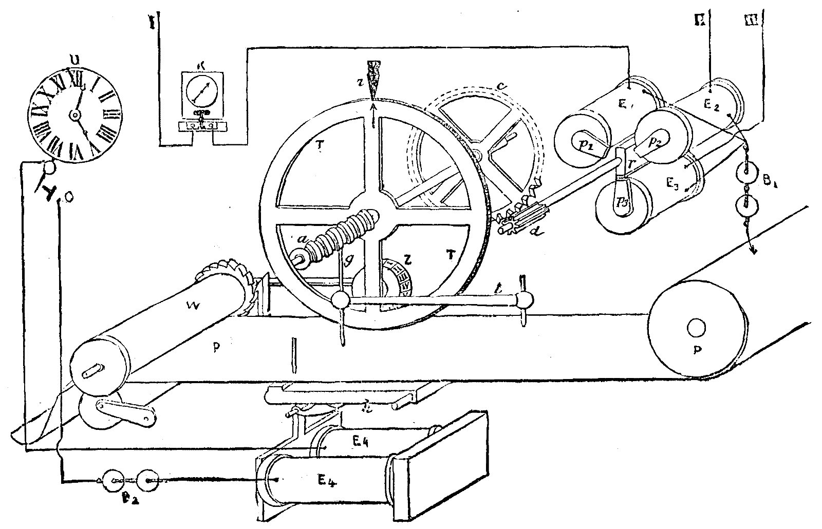
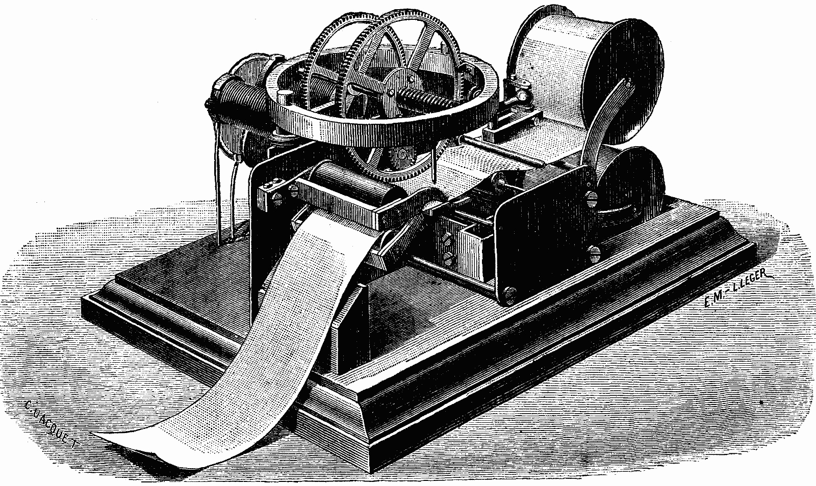
This stated, the play of the apparatus may be easily understood. Every ten minutes a regulating clock closes the circuit of the local pile, B2, and establishes a contact at C. The electro-magnet, E4, attracts its armature, and thus acts upon the lever, h, which presses the sheet of paper against the stylet in front that serves to mark the level of the lowest waters, and against the stylet, g, and the wheels, T and Z. In falling back, the lever, h, causes the advance, by one notch, of the ratchet wheel that is mounted at the extremity of the cylinder W, and thus displaces the sheet of paper a distance of 5 mm. The wheel, Z, carries engraved in projection upon its circumference the hours in Roman figures, and moves forward one division every 60 minutes. The motion of this wheel is likewise controlled by the cylinder, W.
This said, the operation of the device is pretty straightforward. Every ten minutes, a timer closes the circuit of the local battery, B2, and creates a connection at C. The electromagnet, E4, pulls its armature, which then moves the lever, h, pressing the sheet of paper against the stylus in front that marks the level of the lowest waters, and against the stylus, g, and the wheels, T and Z. When the lever, h, returns, it advances the ratchet wheel at the end of the cylinder W by one notch, moving the sheet of paper 5 mm. The wheel, Z, has the hours engraved on its edge in Roman numerals and moves forward one division every 60 minutes. The motion of this wheel is also managed by the cylinder, W.
It will be seen upon referring to Fig. 7, that there is obtained a very sharp curve marked by points. We have a general view on considering the curve itself, and the height in meters is read directly. The fractions of a meter, as well as the times, are in the margin. Thus, at the point, a, the apparatus gives at 3 o'clock and 20 minutes a height of tide of 4.28 m. above the level of the lowest water.
It can be observed by looking at Fig. 7 that there is a very sharp curve marked by points. We get a general view when considering the curve itself, and the height in meters can be read directly. The fractions of a meter, along with the times, are in the margin. So, at the point, a, the apparatus indicates that at 3:20 PM, the tide height is 4.28 m above the lowest water level.
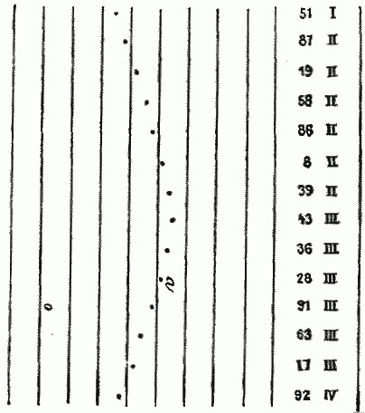
This apparatus might possibly operate well, and yet not be in accord with the real indications of the float, so it has been judged necessary to add to it the following control.
This device might work well, but it may not align with the actual readings of the float, so it's been deemed necessary to add the following control.
Every time the float reaches 3 meters above the level of the lowest tide, the circuit of one of the lines that is open at this moment (that of line I, for example) closes at C (Fig. 2), into this new circuit there is interposed a considerable resistance, W, so that the energy of the current is weakened to such a point that it in nowise influences the normal travel of the wheel, r. At the shore station, there is placed in deviation a galvanoscope, K, whose needle is deflected. It suffices, then, to take datum points upon the registering apparatus, upon the wheel, T, and the screw, a, in such a way as to ascertain the moment at which the stylet, g, is going to mark 3 meters. At this moment the circuit of the galvanoscope, K, is closed, and we ascertain whether there is a deviation of the needle.
Every time the float rises to 3 meters above the lowest tide, the circuit of one of the lines that is active at that moment (like line I, for example) closes at C (Fig. 2). In this new circuit, there’s a significant resistance, W, which weakens the current's energy to the point where it doesn’t affect the normal operation of the wheel, r. At the shore station, there’s a galvanoscope, K, set up in a way that its needle is deflected. It’s enough to take reference points on the recording device, on the wheel, T, and the screw, a, to determine the moment when the stylet, g, will indicate 3 meters. At this moment, the circuit of the galvanoscope, K, closes, and we check for needle deflection.
As the sea generally rises to the height of 3 meters twice a day, it is possible to control the apparatus twice a day, and this is fully sufficient.
As the sea usually rises to a height of 3 meters twice daily, it's feasible to operate the apparatus twice a day, and this is more than enough.
It always belongs to practice to judge of an invention. Mr. Von Hefner-Alteneck tells us that two of these apparatus have been set up—one of them a year ago in the port of Kiel, and the other more recently at the Isle of Wangeroog in the North Sea—and that both have behaved excellently since the very first day of their installation. We shall add nothing to this, since it is evidently the best eulogium that can be accorded them.—La Lumiere Electrique.
It’s always important to put an invention to the test. Mr. Von Hefner-Alteneck informs us that two of these devices have been installed—one a year ago in the port of Kiel and the other more recently on the Isle of Wangeroog in the North Sea—and that both have performed excellently right from their first day of operation. We won’t add anything to this, as it clearly serves as the best praise they could receive.—La Lumiere Electrique.
DELUNE & CO.'S SYSTEM OF LAYING UNDERGROUND CABLES.
In recent times considerable attention has been paid to the subject of laying telegraph cables underground, and various methods have been devised. In some cases the cables have been covered with an armor of iron, and in others they have been inclosed in cast-iron pipes. For telephonic service they are generally inclosed in leaden tubes. What this external envelope shall be that is to protect the wires from injury is a question of the highest importance, since not only the subject of protection is concerned, but also that of cost. It is therefore interesting to note the efforts that are being made in this line of electric industry.
In recent times, there has been a lot of focus on the topic of burying telegraph cables underground, and various methods have been developed. In some cases, the cables have been covered with an iron armor, while in others, they have been enclosed in cast-iron pipes. For telephone service, they are usually enclosed in lead tubes. The choice of what external covering will protect the wires from damage is crucial, as it involves both protection and cost. It’s interesting to observe the efforts being made in this area of the electrical industry.


Messrs. Delune & Co. have recently taken out a patent for an arrangement consisting of pipes made of beton. The annexed cuts, borrowed from L'Electricite, represent this new system. The pipes, which are provided with a longitudinal opening, are placed end to end and coupled with a cement sleeve. The cables are put in place by simply unwinding them as the work proceeds, and thus all that traction is done away with that they are submitted to when cast iron pipes are used. When once the cables are in place the longitudinal opening is stopped up with cement mortar, and in this way a very tight conduit is obtained whose hardness increases with time. The value of the system therefore depends, as in all cement work, on the care with which the manufacturing is done.
Messrs. Delune & Co. have recently acquired a patent for a setup that involves pipes made of concrete. The attached images, taken from L'Electricite, illustrate this new system. The pipes, which have a long opening, are connected end to end and joined with a cement sleeve. The cables are installed by simply unwinding them as the work progresses, eliminating the stress they experience when cast iron pipes are used. Once the cables are in place, the long opening is sealed with cement mortar, creating a very tight conduit that becomes harder over time. Thus, the effectiveness of the system relies, as in all cement construction, on the quality of the manufacturing process.
Experiments have been made with the system at Toulouse, by the Minister of Post Offices and Telegraphs, and at Lyons, by the General Society of Telephones. Here, as with all similar questions, no opinion can be pronounced until after a prolonged experience. But we cannot help setting forth the advantages that the system offers. These are, in the first place, a saving of about 50 per cent. over iron pipe, and in the second, a better insulation, and consequently a better protection of the currents against all kinds of disturbance, since a non-conducting mass of cement is here substituted for metal.
Experiments have been conducted with the system in Toulouse by the Minister of Post Offices and Telegraphs, and in Lyons by the General Society of Telephones. As with all similar issues, no conclusions can be drawn until there has been extensive experience. However, we can't help but highlight the benefits that the system provides. First, it offers a saving of about 50 percent compared to iron pipes, and second, it provides better insulation, which in turn offers better protection for the currents against various disturbances, as a non-conductive mass of cement replaces metal.
ELECTRICITY APPLIED TO HORSE-SHOEING.
"There is nothing new but what has been forgotten," said Marie Antoinette to her milliner, Mdlle. Bertin, and what is true of fashion is also somewhat so of science. Shoeing restive horses by the aid of electricity is not new, experiments thereon having been performed as long ago as 1879 by Mr. Defoy, who operated with a small magneto machine.
"There’s nothing new except what has been forgotten," said Marie Antoinette to her hat maker, Mdlle. Bertin, and what’s true for fashion is also somewhat true for science. Shoeing restless horses using electricity isn’t new; experiments on this were carried out as early as 1879 by Mr. Defoy, who worked with a small magneto machine.
But the two photographs reproduced in Figs. 1 and 2 have appeared to us curious enough to be submitted to our readers, as illustrating Mr. Defoy's method of operating with an unruly animal.
But the two photographs shown in Figs. 1 and 2 seem interesting enough to share with our readers, as they illustrate Mr. Defoy's approach to handling a difficult animal.
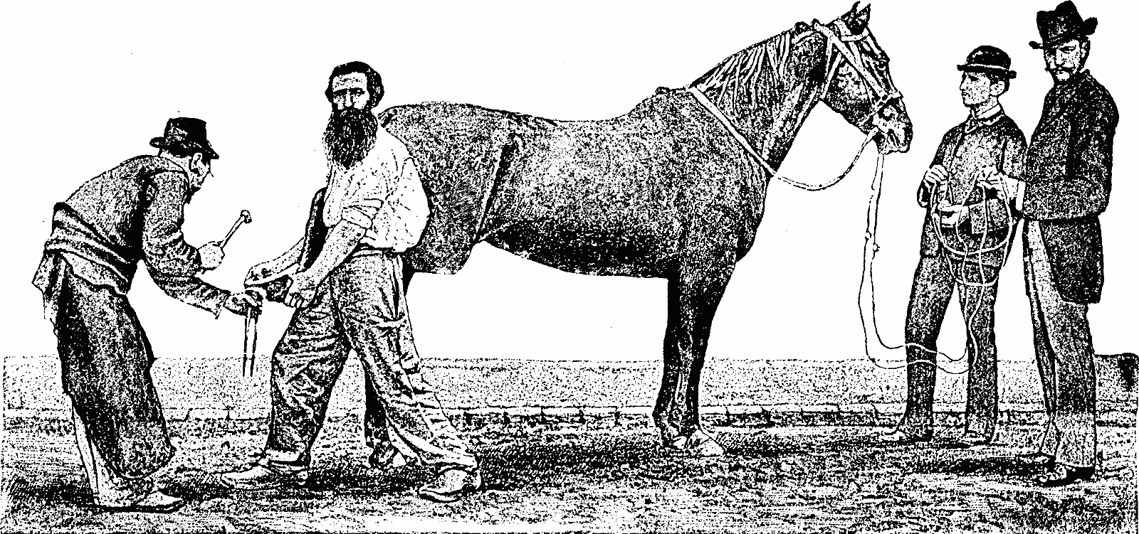
The battery used was a small Grenet bichromate of potash pile, which was easy to graduate on account of the depth to which the zinc could be immersed. This pile was connected with the inductor of a small Ruhmkorff coil, whose armature was connected with a snaffle-bit placed in the horse's mouth.
The battery used was a small Grenet bichromate of potash pile, which was easy to adjust because of how deep the zinc could be immersed. This pile was connected to the inductor of a small Ruhmkorff coil, whose armature was connected to a snaffle-bit placed in the horse's mouth.
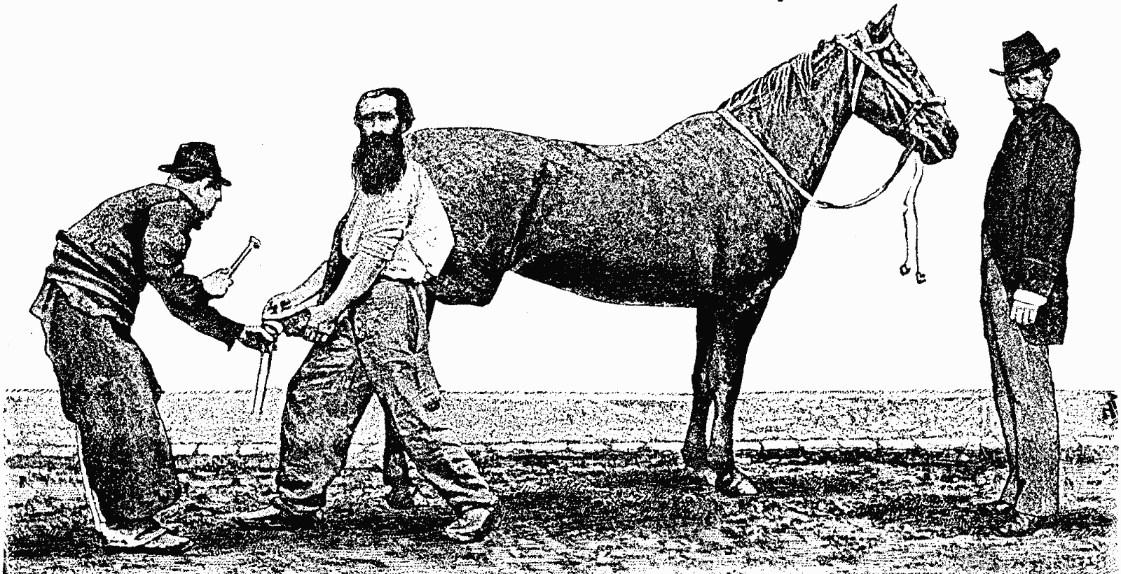
This bit was arranged as follows (Fig. 3): The two conductors, which were uncovered for a length of about three centimeters at their extremity, were placed opposite each other on the two joints of the snaffle, and about five or six centimeters apart. The mouth-pieces of the bit had previously been inclosed in a piece of rubber tubing, in order to insulate the extremities of the conductors and permit the recomposition of the current to take place through the animal's tongue or palate.
This setup was organized like this (Fig. 3): The two conductors, which were exposed for about three centimeters at their ends, were positioned facing each other on the two joints of the snaffle, and about five or six centimeters apart. The mouthpieces of the bit had previously been covered with a piece of rubber tubing, to insulate the ends of the conductors and allow the current to flow through the animal's tongue or palate.
Each of the bare ends of the conductors was provided, under a circular brass ligature, with a small damp sponge, which, surrounding the mouth-piece, secured a perfect contact of each end of the circuit with the horse's mouth.
Each bare end of the conductors was fitted, under a circular brass band, with a small damp sponge, which, encircling the mouthpiece, ensured a perfect connection of each end of the circuit with the horse's mouth.
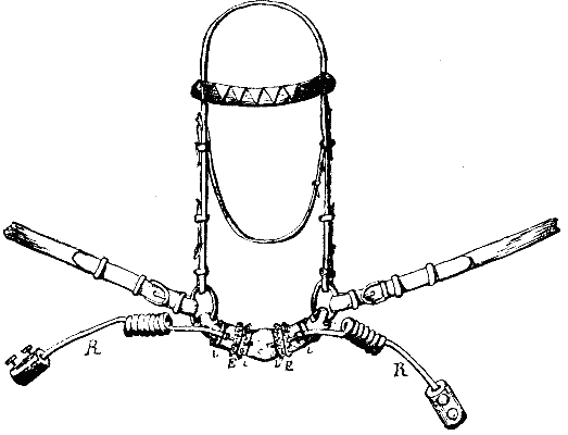
The horse having been led in, defended himself vigorously as long as an endeavor was made to remove his shoes by the ordinary method, but the current had acted scarcely fifteen seconds when it became possible to lift his feet and strike his shoes with the hammer.
The horse was brought in and fought back fiercely as long as someone tried to take off his shoes the usual way, but after only about fifteen seconds, it was possible to lift his feet and hit his shoes with the hammer.
The experimenter having taken care during this experiment to place the bobbin quite near the horse's ear, so that he could hear the humming of the interrupter, undertook a second experiment in the following way: Having detached the conductors from the armature, he placed himself in front of the horse (as shown in Fig. 2), and began to imitate the humming sound of the interrupter with his mouth. The animal at once assumed the stupefied position that the action of the current gave him in the first experiment, and allowed his feet to be lifted and shod without his even being held by the snaffle.
The experimenter made sure to place the bobbin close to the horse's ear during this experiment, so it could hear the humming of the interrupter. He then performed a second experiment in the following way: After detaching the conductors from the armature, he stood in front of the horse (as shown in Fig. 2) and started to mimic the humming sound of the interrupter with his mouth. Instantly, the horse took on the dazed position it had during the first experiment, allowing its feet to be lifted and shod without even needing to be held by the snaffle.
The horse was for ever after subdued, and yet his viciousness and his repugnance to shoeing were such that he could only be shod previously by confining his legs with a kicking-strap.
The horse was forever subdued, yet his aggression and refusal to be shod were so strong that he could only be fitted with shoes by restraining his legs with a kicking strap.
It should be noted that the action of the induction coil, mounted as this was, was very feeble and not very painful; and yet it was very disagreeable in the mouth, and gave in this case a shock with a sensation of light before the eyes, as we have found by experimenting upon ourselves.
It’s important to mention that the induction coil’s action, set up like this, was quite weak and not very painful; however, it was really uncomfortable in the mouth and, in this instance, delivered a shock that came with a sensation of light in front of the eyes, as we discovered through our own experiments.
From our own most recent experiments, we have ascertained the following facts, which may guide every horse-owner in the application of electricity to an animal that is opposed to being shod: (1) To a horse that defends himself because he is irritable by temperament, and nervous and impressionable (as happens with animals of pure or nearly pure blood), the shock must be administered feebly and gradually before an endeavor is made to take hold of his leg. The horse will then make a jump, and try to roll over. The jump must be followed, while an assistant holds the bridle, and the action of the current must be at once arrested. After this the horse will not endeavor to defend himself, and his leg may be easily handled.
From our latest experiments, we've identified some facts that can help every horse owner apply electricity safely to a horse that resists being shod: (1) For a horse that reacts defensively due to irritability, nervousness, or sensitivity (which often occurs in purebred or nearly purebred animals), the shock should be delivered gently and gradually before attempting to touch his leg. The horse may then jump and try to roll over. This jump should be followed while someone holds the bridle, and the current should be stopped immediately. After this, the horse will no longer try to resist, and his leg can be handled easily.
(2) Certain large, heavy, naturally ugly horses kick through sheer viciousness. In this case, while the current is being given it should be gradually increased in intensity, and the horse's foot must be seized during its action. In most cases the passage of a current through such horses (whose mucous membrane is less sensitive) produces only a slightly stupefied and contracted position of the head, accompanied with a slight tremor. The current must be shut off as soon as the horse's foot is well in one's hand, and be at once renewed if he endeavors to defend himself again, as is rarely the case. It is a mare of this nature that is represented in the annexed figures.
(2) Some large, heavy, naturally unattractive horses kick out of pure aggression. In this situation, while the electric current is being applied, it should be gradually intensified, and the horse's foot must be held firmly during the process. Usually, the current passing through these horses (whose mucous membranes are less sensitive) results in only a slightly dazed and tense position of the head, along with a slight tremor. The current should be turned off as soon as the horse's foot is securely held, and it should be restarted immediately if the horse tries to protect itself again, though that rarely happens. A mare like this is shown in the attached figures.
We know that this same system has been applied for bringing to an abrupt standstill runaway horses, harnessed to vehicles; but knowing the effect of a sudden stoppage under such circumstances, we believe that the remedy would prove worse than the disease, since the coachman and vehicle, in obedience to the laws of inertia, would continue their motion and pass over the animals, much to their detriment.—Science et Nature.
We know that this same system has been used to suddenly stop runaway horses that are hitched to vehicles; however, understanding the impact of a sudden stop in such situations, we think the solution would be worse than the problem, since the coachman and vehicle, following the laws of inertia, would keep moving and run over the animals, which would be very harmful to them.—Science et Nature.
ESTEVE'S AUTOMATIC PILE.
Mr. Esteve has recently devised a generator of electricity which he claims to be energetic, constant, and always ready to operate. The apparatus is designed for the production of light and for actuating electric motors, large induction bobbins, etc.
Mr. Esteve has recently created an electricity generator that he claims is powerful, reliable, and always ready to use. The device is designed for producing light and powering electric motors, large induction coils, and more.
We give a description of it herewith from data communicated by its inventor.
We provide a description of it here based on information shared by its inventor.
The accompanying cut represents a battery of 6 elements, with a reservoir, R, for the liquid, provided at its lower part with a cock for allowing the liquid to enter the pile. The vessels of the different elements are of rectangular form. At the upper part, and in the wider surfaces of each, there are two tubes. The first tube of the first vessel receives the extremity of a safety-tube, A, whose other extremity enters the upper part of the reservoir, R. This tube is designed for regulating the flow of the liquid into the pile. When the cock, r, is too widely open, the liquid might have a tendency to flow over the edges of the vessel; but this would close the orifice of the tube, A, and, as the air would then no longer enter the reservoir, R, the flow would be stopped automatically. The second tube of the first vessel is connected with a lead tube, 1, one of the extremities of which enters the second vessel. The other tubes are arranged in the same way in the other vessels. The renewal of the liquids is effected by displacement, in flowing upward from one element over into another; and the liquids make their exit from the pile at D, after having served six times. The electrodes of the two first elements are represented as renewed in the cut, in order to show the arrangement of the tubes.
The accompanying diagram shows a battery with 6 components, featuring a reservoir, R, for the liquid. At the bottom, there's a valve that allows the liquid to flow into the battery. The containers for each component are rectangular. At the top, on the wider surfaces of each, there are two tubes. The first tube of the first container connects to the end of a safety tube, A, which extends into the top of the reservoir, R. This tube is meant to control the liquid flow into the battery. If the valve, r, is opened too wide, the liquid might spill over the edges of the container. However, this would block the opening of the tube, A, and since air could no longer enter the reservoir, R, the flow would automatically stop. The second tube of the first container connects to a lead tube, 1, one end of which goes into the second container. The other tubes are arranged similarly in the other containers. The liquids are refreshed through displacement, flowing upward from one component to another, and they exit the battery at D after passing through six times. The electrodes of the first two components are shown as renewed in the diagram to illustrate the tube layout.
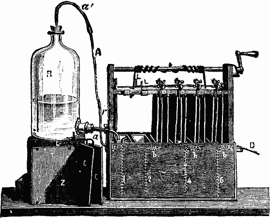
ESTEVE'S AUTOMATIC PILE.
Dimensions.—The zinc, 2, has a superficies of 15×20 centimeters, and is cut out of the ordinary commercial sheet metal. It may be turned upside down when one end has become worn away, thus permitting of its being entirely utilized. The negative electrode is formed of four carbons, which have, each of them, a superficies of 8×21 centimeters. These four carbons are less fragile and are more easily handled than two having the same surface. Their arrangement is shown at the left of the figure. They are fixed to a strip of copper, a, to which is soldered another strip, L, bent at right angles. There are thus two pairs of carbon per element, and these are simply suspended from a piece of wood, as shown in the figure. Upon this wooden holder will be seen the two strips, LL, that are designed to be put in contact with the zinc of the succeeding element by means of pinchers that connect the electrodes with one another. This arrangement permits the pile to be taken apart very quickly.
Dimensions.—The zinc, 2, has a surface area of 15×20 centimeters and is cut from standard commercial sheet metal. It can be flipped over when one end gets worn out, allowing for complete use. The negative electrode consists of four carbons, each with a surface area of 8×21 centimeters. These four carbons are sturdier and easier to handle than two with the same surface area. Their setup is shown on the left of the figure. They are attached to a copper strip, a, which is soldered to another strip, L, bent at a right angle. This creates two pairs of carbon for each element, which are simply suspended from a piece of wood, as depicted in the figure. On this wooden holder, you will see the two strips, LL, designed to connect with the zinc of the next element using pinchers that link the electrodes together. This setup allows for the pile to be disassembled quickly.
Charging, Work, and Duration of the Pile.—The inventor has made a large number of experiments with solutions of bichromate of potash of various degrees of saturation, and has found the following to give the best results:
Charging, Work, and Duration of the Pile.—The inventor has conducted numerous experiments with solutions of potassium bichromate at different saturation levels, and found the following to produce the best results:
| Bichromate of potash. | 1 | kilogramme. |
| Sulphuric acid | 2 | liters. |
| Water | 8 | " |
When a larger quantity of the salt is used, crystallization occurs in the pile.
When a larger amount of salt is used, crystallization happens in the pile.
| Constants and work of an element having a zinc of 16×20 cm. | Constants and work of a round Bunsen element, 20×30 cm. | |
| Volts. | 1.9 | 1.8 |
| Resistance. | 0.05 | 0.24 |
| Work disposable in the external circuit. | 1.839 k. | 0.344 k. |
The work disposable in the external circuit is deduced from the formula:
The work done in the external circuit is calculated using the formula:
| T = | E² (4R × 9.81) (4R × 9.81) |
It will be seen that an element thus charged gives as much energy as 5.3 large Bunsen elements.
It will be seen that a charged element provides as much energy as 5.3 large Bunsen elements.
The battery is charged with 10 liters of solution, and is capable of furnishing for 5 hours a current of 7 amperes with a difference of potential of 9 volts at the pile terminals. The work, according to the formula (EI)/g, equals 6.422 kilogram-meters; with a feebler resistance in the external circuit it is capable of producing a current of 19 amperes for an hour and an half. In this case the resistance of the external circuit equals the interior resistance of the pile. Upon immersing the electrodes in new liquid, and with no resistance in the external circuit, the current may reach 100 amperes. On renewing the liquids during the operation of the pile, a current of 7 amperes is kept up if about a liter of saturation per hour be allowed to pass into the battery. For five hours, then, only 5 liters are used instead of the 10 that are necessary when the liquid is not renewed while the pile is in action.—La Nature.
The battery holds 10 liters of solution and can provide a current of 7 amperes for 5 hours with a voltage of 9 volts at the terminals. The energy output, based on the formula (EI)/g, equals 6.422 kilogram-meters. With lower resistance in the external circuit, it can generate a 19-ampere current for 1.5 hours. In this scenario, the external circuit's resistance matches the battery's internal resistance. When the electrodes are placed in fresh liquid and there’s no resistance in the external circuit, the current can go up to 100 amperes. By refreshing the liquid during the battery's operation, a steady current of 7 amperes is maintained if about a liter of saturation is allowed to flow into the battery each hour. Therefore, over five hours, only 5 liters are consumed instead of the 10 liters needed when the liquid isn't replenished while the battery is running.—La Nature.
WOODWARD'S DIFFUSION MOTOR.
The energy produced by the phenomena of diffusion is exhibited in lecture courses by placing a bell glass filled with hydrogen over a porous vessel at whose base is fixed a glass tube that dips into water. The hydrogen, in diffusing, enters the porous vessel, increases the internal pressure, and a number of bubbles escapes from the tube. On withdrawing the bell glass of hydrogen, the latter becomes diffused externally, a lower pressure occurs in the porous vessel, and the level of the water rises.
The energy produced by diffusion can be demonstrated in lectures by placing a glass bell jar filled with hydrogen over a porous container that has a glass tube fixed at the bottom, dipping into water. As the hydrogen diffuses, it enters the porous container, increasing the internal pressure, and bubbles escape from the tube. When the bell jar of hydrogen is removed, the hydrogen diffuses into the surrounding air, creating a lower pressure in the porous container, causing the water level to rise.
The arrangement devised by Mr. C.J. Woodward, and recently presented to the Physical Society of London, is an adaptation of this experiment to the production of an oscillating motion by alternations in the internal and external diffusion of the hydrogen.
The setup created by Mr. C.J. Woodward, and recently showcased to the Physical Society of London, is a modification of this experiment aimed at generating oscillating motion through changes in the internal and external diffusion of hydrogen.
The apparatus, represented herewith, consists of a scale beam about three feet in length that supports at one end a scale pan and weights, and, at the other, a corked porous vessel that carries a glass tube, c, which dips into a vessel containing either water or methylic alcohol. Three or four gas jets, one of which is shown at E, are arranged around the porous vessel, as close as possible, but in such a way as not to touch it during the oscillation of the beam. These gas jets communicate with a gasometer tilled with hydrogen, the bell of which is so charged as to furnish a jet of sufficient strength. Experience will indicate the best place to give the gas jets, but, in general, it is well to locate them at near the center of the porous vessel when the beam is horizontal.
The setup described here consists of a scale beam about three feet long that holds a scale pan and weights on one end, and a corked porous vessel on the other end that has a glass tube, c, dipping into a container with either water or methylic alcohol. Three or four gas jets, one of which is shown at E, are positioned around the porous vessel as close as possible without touching it while the beam is in motion. These gas jets are connected to a gasometer filled with hydrogen, which is charged to provide a strong enough jet. Experience will help determine the best placement for the gas jets, but generally, it’s advisable to position them near the center of the porous vessel when the beam is horizontal.
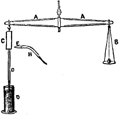
It is now easy to see how the device operates. When the hydrogen comes in presence of the porous vessel it becomes diffused therein, and the pressure exerted in the interior then produces an ascent. When the bottom of the porous vessel gets above the jets, the internal diffusion ceases and the hydrogen becomes diffused externally, the internal pressure diminishes, and the vessel descends. The vessel then comes opposite the jets of hydrogen and the same motion occurs again, and soon indefinitely. The work produced by this motor, which has purely a scientific interest, is very feeble, and much below that assigned to it by theory. In order to obtain a maximum, it would be necessary to completely surround the porous vessel each time with hydrogen, and afterward remove the jets to facilitate the access of air. All the mechanical arrangements employed for obtaining such a result have failed, because the friction introduced by the maneuvering parts also introduces a resistance greater than the motor can overcome. There is therefore a waste of energy due to the continuous flow of hydrogen; but the apparatus, for all that, constitutes none the less an original and interesting device.—La Nature.
It’s now easy to understand how the device works. When hydrogen encounters the porous vessel, it spreads throughout it, and the pressure inside causes it to rise. When the bottom of the porous vessel goes above the jets, the internal diffusion stops, and the hydrogen then diffuses outside, leading to a decrease in internal pressure, which causes the vessel to descend. The vessel then aligns with the hydrogen jets, and the same movement repeats, and continues indefinitely. The work done by this motor, which is purely for scientific purposes, is quite weak and significantly less than what was predicted by theory. To achieve maximum efficiency, it would be necessary to completely envelop the porous vessel with hydrogen each time and then remove the jets to allow air in. However, all mechanical systems designed to achieve this result have failed because the friction from the moving parts creates a resistance greater than what the motor can handle. Therefore, there is an energy loss due to the continuous flow of hydrogen; nevertheless, the apparatus is still an original and interesting device.—La Nature.
SOME RELATIONS OF HEAT TO VOLTAIC AND THERMO-ELECTRIC ACTION OF METALS IN ELECTROLYTES.1
By G. GORE, F.R.S., LL.D.
The experiments described in this paper throw considerable light upon the real cause of the voltaic current. The results of them are contained in twenty tables; and by comparing them with each other, and also by means of additional experiments, the following general conclusions and chief facts were obtained.
The experiments detailed in this paper provide significant insights into the actual cause of the voltaic current. The results are presented in twenty tables, and by comparing these tables with one another, along with additional experiments, the following general conclusions and key facts were reached.
When metals in liquids are heated, they are more frequently rendered positive than negative in the proportion of about 2.8 to 1.0; and while the proportion in weak solutions was about 2.29 to 1.0, in strong ones it was about 3.27 to 1.0, and this accords with their thermo-electric behavior as metals alone. The thermo-electric order of metals in liquids was, with nearly every solution, whether strong or weak, widely different from the thermo-electric order of the same metals alone. A conclusion previously arrived at was also confirmed, viz., that the liquids in which the hot metal was thermo-electro-positive in the largest proportion of cases were those containing highly electro-positive bases, such as the alkali metals. The thermo-electric effect of gradually heating a metal in a liquid was sometimes different from that of suddenly heating it, and was occasionally attended by a reversal of the current.
When metals in liquids are heated, they tend to become positive more often than negative, with a ratio of about 2.8 to 1.0. In weak solutions, this ratio is about 2.29 to 1.0, while in strong solutions, it rises to about 3.27 to 1.0, which aligns with how metals behave thermo-electrically on their own. The thermo-electric order of metals in liquids varied significantly from that of the same metals in isolation, regardless of whether the solution was strong or weak. This also confirmed a previous conclusion that the liquids in which hot metal showed thermo-electro-positive behavior most frequently contained highly electro-positive bases, like alkali metals. The thermo-electric effect of gradually heating a metal in a liquid sometimes differed from that of suddenly heating it and occasionally led to a reversal of the current.
Degree of strength of liquid greatly affected the thermo-electric order of metals. Increase of strength usually and considerably increased the potential of metals thermo-electro-negative in liquids, and somewhat increased that of those positive in liquids.
The strength of a liquid significantly influenced the thermo-electric properties of metals. An increase in strength typically and greatly raised the potential of metals that are thermo-electro-negative in liquids, while also slightly increasing that of those that are positive in liquids.
The electric potential of metals, thermo-electro-positive in weak liquids, was usually about 3.87 times, and in strong ones 1.87 times, as great as of those which were negative. The potential of the strongest thermo-electric couple, viz., that of aluminum in weak solution of sodic phosphate, was 0.66 volt for 100° F. difference of temperature, or about 100 times that of a bismuth and antimony couple.
The electric potential of metals that are thermo-electro-positive in weak liquids was generally about 3.87 times greater, and in strong ones 1.87 times greater, than those that were negative. The potential of the strongest thermo-electric couple, specifically that of aluminum in a weak solution of sodium phosphate, was 0.66 volts for a 100°F temperature difference, or about 100 times that of a bismuth and antimony couple.
Heating one of the metals, either the positive or negative, of a voltaic couple, usually increased their electric difference, making most metals more positive, and some more negative; while heating the second one also usually neutralized to a large extent the effect of heating the first one. The electrical effect of heating a voltaic couple is nearly wholly composed of the united effects of heating each of the two metals separately, but is not however exactly the same, because while in the former case the metals are dissimilar, and are heated to the same temperature, in the latter they are similar, but heated to different temperatures. Also, when heating a voltaic pair, the heat is applied to two metals, both of which are previously electro-polar by contact with each other as well as by contact with the liquid; but when heating one junction of a metal and liquid couple, the metal has not been previously rendered electro-polar by contact with a different one, and is therefore in a somewhat different state. When a voltaic combination, in which the positive metal is thermo-negative, and the negative one is thermo-positive, is heated, the electric potential of the couple diminishes, notwithstanding that the internal resistance is decreased.
Heating one of the metals, whether it's the positive or negative one, in a voltaic couple usually increases their electric potential, making most metals more positive and some more negative. At the same time, heating the second metal generally cancels out a lot of the effects from heating the first one. The electrical effect from heating a voltaic couple mainly comes from the combined effects of heating each metal separately, but it’s not exactly the same because in the first case the metals are different but heated to the same temperature, while in the other case they are similar but heated to different temperatures. Additionally, when you heat a voltaic pair, the heat is applied to two metals that have already become electro-polar due to contact with each other and with the liquid. However, when heating just one junction of a metal and liquid couple, the metal hasn’t been made electro-polar by contact with a different material, putting it in a different state. If a voltaic combination has the positive metal as thermo-negative and the negative one as thermo-positive and it’s heated, the electric potential of the couple decreases even though the internal resistance goes down.
Magnesium in particular, also zinc and cadmium, were greatly depressed in electromotive force in electrolytes by elevation of temperature. Reversals of position of two metals of a voltaic couple in the tension series by rise of temperature were chiefly due to one of the two metals increasing in electromotive force faster than the other, and in many cases to one metal increasing and the other decreasing in electromotive force, but only in a few cases was it a result of simultaneous but unequal diminution of potential of the two metals. With eighteen different voltaic couples, by rise of temperature from 60° to 160° F., the electromotive force in twelve cases was increased, and in six decreased, and the average proportions of increase for the eighteen instances was 0.10 volt for the 100° F. of elevation.
Magnesium, along with zinc and cadmium, showed a significant drop in electromotive force in electrolytes when the temperature increased. The changes in the order of two metals in a voltaic couple’s tension series due to rising temperatures were mostly because one metal’s electromotive force increased faster than the other’s. In many cases, one metal increased while the other decreased in electromotive force, but only in a few instances was it a result of both metals losing potential at different rates. With eighteen different voltaic couples, as the temperature rose from 60° to 160° F., the electromotive force increased in twelve cases and decreased in six. On average, the increase across all eighteen cases was 0.10 volt for every 100° F. rise in temperature.
A great difference in chemical composition of the liquid was attended by a considerable change in the order of the volta-tension series, and the differences of such order in two similar liquids, such as solutions of hydric chloride and potassic chloride, were much greater than those produced in either of those liquids by a difference of 100° F. of temperature. Difference of strength of solution, like difference of composition or of temperature, altered the order of such series with nearly every liquid; and the amount of such alteration by an increase of four or five times in the strength of the liquid was rather less than that caused by a difference of 100° F. of temperature. While also a variation of strength of liquid caused only a moderate amount of change of order in the volta-tension series, it produced more than three times that amount of change in the thermo-electric tension series. The usual effect of increasing the strength of the liquid upon the volta-electromotive force was to considerably increase it, but its effect upon the thermo-electro-motive force was to largely decrease it. The degree of potential of a metal and liquid thermo-couple was not always exactly the same at the same temperature during a rise as during a fall of temperature; this is analogous to the variations of melting and solidifying points of bodies under such conditions, and also to that of supersaturation of a liquid by a salt, and is probably due to some hinderance to change of molecular movement.
A significant difference in the chemical composition of the liquid was accompanied by a noticeable change in the order of the volta-tension series, and the differences in that order between two similar liquids, like solutions of hydrochloric acid and potassium chloride, were much greater than those caused by a temperature difference of 100°F in either liquid. Changes in solution strength, similar to changes in composition or temperature, altered the order of the series for nearly every liquid; the impact of increasing the strength of the liquid by four or five times was somewhat less than the effect of a 100°F temperature difference. While a variation in liquid strength only caused a moderate change in the order of the volta-tension series, it resulted in more than three times that change in the thermo-electric tension series. Typically, increasing the strength of a liquid significantly boosted the volta-electromotive force, but it largely reduced the thermo-electromotive force. The potential of a metal and liquid thermo-couple wasn’t always the exact same at the same temperature during warming and cooling; this is similar to how melting and solidifying points of substances can vary under such conditions, and it also relates to the supersaturation of a liquid by a salt, likely due to some restriction on changes in molecular movement.
The rate of ordinary chemical corrosion of each metal varied in every different liquid; in each solution also it differed with every different metal. The most chemically positive metals were usually the most quickly corroded, and the corrosion of each metal was usually the fastest with the most acid solutions. The rate of corrosion at any given temperature was dependent both upon the nature of the metal and upon that of the liquid, and was limited by the most feebly active of the two, usually the electrolyte. The order of rate of corrosion of metals also differed in every different liquid. The more dissimilar the chemical characters of two liquids, the more diverse usually was the order of rapidity of corrosion of a series of metals in them. The order of rate of simple corrosion in any of the liquids examined differed from that of chemico-electric and still more from that of thermo-electric tension. Corrosion is not the cause of thermo-electric action of metals in liquids.
The rate of regular chemical corrosion for each metal varied in every different liquid; it also differed for each metal in every solution. The most chemically active metals were usually the ones that corroded the fastest, and the corrosion of each metal was generally quickest in the most acidic solutions. The rate of corrosion at any temperature depended on both the type of metal and the nature of the liquid, and was limited by the least active of the two, typically the electrolyte. The order of corrosion rates among metals also changed with every different liquid. The more different the chemical properties of two liquids, the more varied the order of corrosion rates for a series of metals in them usually was. The order of simple corrosion rates in any of the liquids examined was different from that of chemical-electric and was even more distinct from that of thermo-electric tension. Corrosion is not responsible for the thermo-electric action of metals in liquids.
Out of fifty-eight cases of rise of temperature the rate of ordinary corrosion was increased in every instance except one, and that was only a feeble exception—the increase of corrosion from 60° to 160° F. with different metals was extremely variable, and was from 1.5 to 321.6 times. Whether a metal increased or decreased in thermo-electromotive force by being heated, it increased in rapidity of corrosion. The proportions in which the most corroded metal was also the most thermo-electro-positive one was 65.57 per cent. in liquids at 60° F., and 69.12 in the same liquids at 160° F.; and the proportion in which it was the most chemico-electro-positive at 60 F. was 84.44 per cent, and at 160° F. 80.77 per cent. The proportion of cases therefore in which the most chemico-electro-negative metal was the most corroded one increased from 15.56 to 19.23 per cent, by a rise of temperature of 100° F. Comparison of these proportions shows that corrosion usually influenced in a greater degree chemico-electric rather than thermo-electric actions of metals in liquids. Not only was the relative number of cases in which the volta-negative metal was the most corroded increased by rise of temperature, but also the average relative loss by corrosion of the negative to that of the positive one was increased from 3.11 to 6.32.
Out of fifty-eight cases of temperature increase, the rate of ordinary corrosion went up in every instance except one, which was a minor exception—the increase of corrosion from 60° to 160° F. across different metals was highly variable, ranging from 1.5 to 321.6 times. Whether heated metal showed an increase or decrease in thermo-electromotive force, it always accelerated corrosion. The most corroded metal was also the most thermo-electro-positive 65.57% of the time in liquids at 60° F., and 69.12% of the time in the same liquids at 160° F.; the proportion where it was the most chemico-electro-positive at 60° F. was 84.44%, and at 160° F. it was 80.77%. Therefore, the proportion of cases where the most chemico-electro-negative metal was the most corroded one rose from 15.56% to 19.23% with a temperature increase of 100° F. Comparing these proportions indicates that corrosion typically had a greater effect on the chemico-electric actions of metals in liquids rather than their thermo-electric actions. Not only did the relative number of cases where the volta-negative metal was the most corroded increase with the rise in temperature, but the average relative loss by corrosion of the negative metal compared to the positive one also increased from 3.11 to 6.32.
The explanation most consistent with all the various results and conclusions is a kinetic one: That metals and electrolytes are throughout their masses in a state of molecular vibration. That the molecules of those substances, being frictionless bodies in a frictionless medium, and their motion not being dissipated by conduction or radiation, continue incessantly in motion until some cause arises to prevent them. That each metal (or electrolyte), when unequally heated, has to a certain extent an unlike class of motions in its differently heated parts, and behaves in those parts somewhat like two metals (or electrolytes), and those unlike motions are enabled, through the intermediate conducting portion of the substance, to render those parts electro-polar. That every different metal and electrolyte has a different class of motions, and in consequence of this, they also, by contact alone with each other at the same temperature, become electro-polar. The molecular motion of each different substance also increases at a different rate by rise of temperature.
The explanation that best fits all the different results and conclusions is a kinetic one: Metals and electrolytes are constantly vibrating at the molecular level. The molecules of these substances, acting as frictionless bodies in a frictionless medium, maintain their motion without losing energy to conduction or radiation, continuing to move until something stops them. Each metal (or electrolyte) that is heated unevenly develops different types of motion in its various heated parts, behaving somewhat like two distinct metals (or electrolytes). These different motions can create an electro-polar effect through the conductive parts of the material. Every type of metal and electrolyte has its own unique set of motions, which means that when they come into contact at the same temperature, they also become electro-polar. Additionally, the molecular motion of each substance increases at different rates with rising temperature.
This theory is equally in agreement with the chemico-electric results. In accordance with it, when in the case of a metal and an electrolyte, the two classes of motions are sufficiently unlike, chemical corrosion of the metal by the liquid takes place, and the voltaic current originated by inherent molecular motion, under the condition of contact, is maintained by the portions of motion lost by the metal and liquid during the act of uniting together. Corrosion therefore is an effect of molecular motion, and is one of the modes by which that motion is converted into and produces electric current.
This theory aligns with the chemico-electric results. According to it, when a metal interacts with an electrolyte and their two types of motion are distinct enough, the metal undergoes chemical corrosion due to the liquid. The voltaic current generated by intrinsic molecular motion, when in contact, is sustained by the motion that is lost by both the metal and the liquid during their union. Therefore, corrosion is a result of molecular motion and is a way that motion is transformed into, and creates, electric current.
In accordance with this theory, if we take a thermo-electric pair consisting of a non-corrodible metal and an electrolyte (the two being already electro-polar by mutual contact), and heat one of their points of contact, the molecular motions of the heated end of each substance at the junction are altered; and as thermo-electric energy in such combinations usually increases by rise of temperature, the metal and liquid, each singly, usually becomes more electro polar. In such a case the unequally heated metal behaves to some extent like two metals, and the unequally heated liquid like two liquids, and so the thermo-electric pair is like a feeble chemico-electric one of two metals in two liquids, but without corrosion of either metal. If the metal and liquid are each, when alone, thermo-electro-positive, and if, when in contact, the metal increases in positive condition faster than the liquid by being heated, the latter appears thermo-electro-negative, but if less rapidly than the liquid, the metal appears thermo-electro-negative.
According to this theory, if we take a thermo-electric pair made up of a non-corrodible metal and an electrolyte (which are already electro-polar due to their contact), and heat one of their contact points, the molecular motions at the heated end of each material at the junction change; and since thermo-electric energy in these combinations generally increases with temperature, both the metal and the liquid tend to become more electro-polar individually. In this situation, the unevenly heated metal acts somewhat like two different metals, and the unevenly heated liquid acts like two different liquids. Thus, the thermo-electric pair resembles a weak chemico-electric setup with two metals in two liquids, but without any corrosion of either metal. If both the metal and the liquid are thermo-electro-positive when they are separate, and if the metal’s positive condition increases faster than the liquid's when heated, the liquid appears thermo-electro-negative. However, if the metal’s positive condition increases more slowly than the liquid’s, the metal appears thermo-electro-negative.
As also the proportion of cases is small in which metals that are positive in the ordinary thermo-electric series of metals only become negative in the metal and liquid ones (viz., only 73 out of 286 in weak solutions, and 48 out of the same number in strong ones), we may conclude that the metals, more frequently than the liquids, have the greatest thermo-electric influence, and also that the relative largeness of the number of instances of thermo-electro-positive metals in the series of metals and liquids, as in the series of metals only, is partly a consequence of the circumstance that rise of temperature usually makes substances—metals in particular—electro-positive. These statements are also consistent with the view that the elementary substances lose a portion of their molecular activity when they unite to form acids or salts, and that electrolytes therefore have usually a less degree of molecular motion than the metals of which they are partly composed.
As the number of cases is small where metals that are positive in the usual thermo-electric series become negative only in combination with liquids (specifically, only 73 out of 286 in weak solutions, and 48 out of the same number in strong ones), we can conclude that metals have a greater thermo-electric influence than liquids. Additionally, the relatively larger number of thermo-electro-positive metals in both the series of metals and liquids, as well as in the series of metals alone, is partly due to the fact that an increase in temperature typically makes substances—particularly metals—more electro-positive. These observations also support the idea that elementary substances lose some of their molecular activity when they combine to form acids or salts, which means that electrolytes generally have less molecular motion than the metals they are made from.
The current from a thermo-couple of metal and liquid, therefore, may be viewed as the united result of difference of molecular motion, first, of the two junctions, and second, of the two heated (or cooled) substances; and in all cases, both of thermo- and chemico-electric action, the immediate true cause of the current is the original molecular vibrations of the substances, while contact is only a static permitting condition. Also that while in the case of thermo-electric action the sustaining cause is molecular motion, supplied by an external source of heat, in the case of chemico-electric action it is the motion lost by the metal and liquid when chemically uniting together. The direction of the current in thermo-electric cases appears to depend upon which of the two substances composing a junction increases in molecular activity the fastest by rise of temperature, or decreases the most rapidly by cooling.
The current from a thermocouple made of metal and liquid can be seen as the combined result of differences in molecular motion, first at the two junctions, and second with the two heated (or cooled) materials. In both thermo-electric and chemico-electric processes, the true source of the current is the original molecular vibrations of the substances, while contact is just a static condition that allows it to happen. Additionally, while in thermo-electric action the sustaining cause is molecular motion provided by an external heat source, in chemico-electric action, it's the motion that the metal and liquid lose when they chemically bond. The direction of the current in thermo-electric cases seems to depend on which of the two substances in a junction increases in molecular activity more quickly with rising temperature or decreases more quickly when cooling down.
Read before the Royal Society, Nov., 1883.
Read before the Royal Society, Nov., 1883.
AIR REFRIGERATING MACHINE.
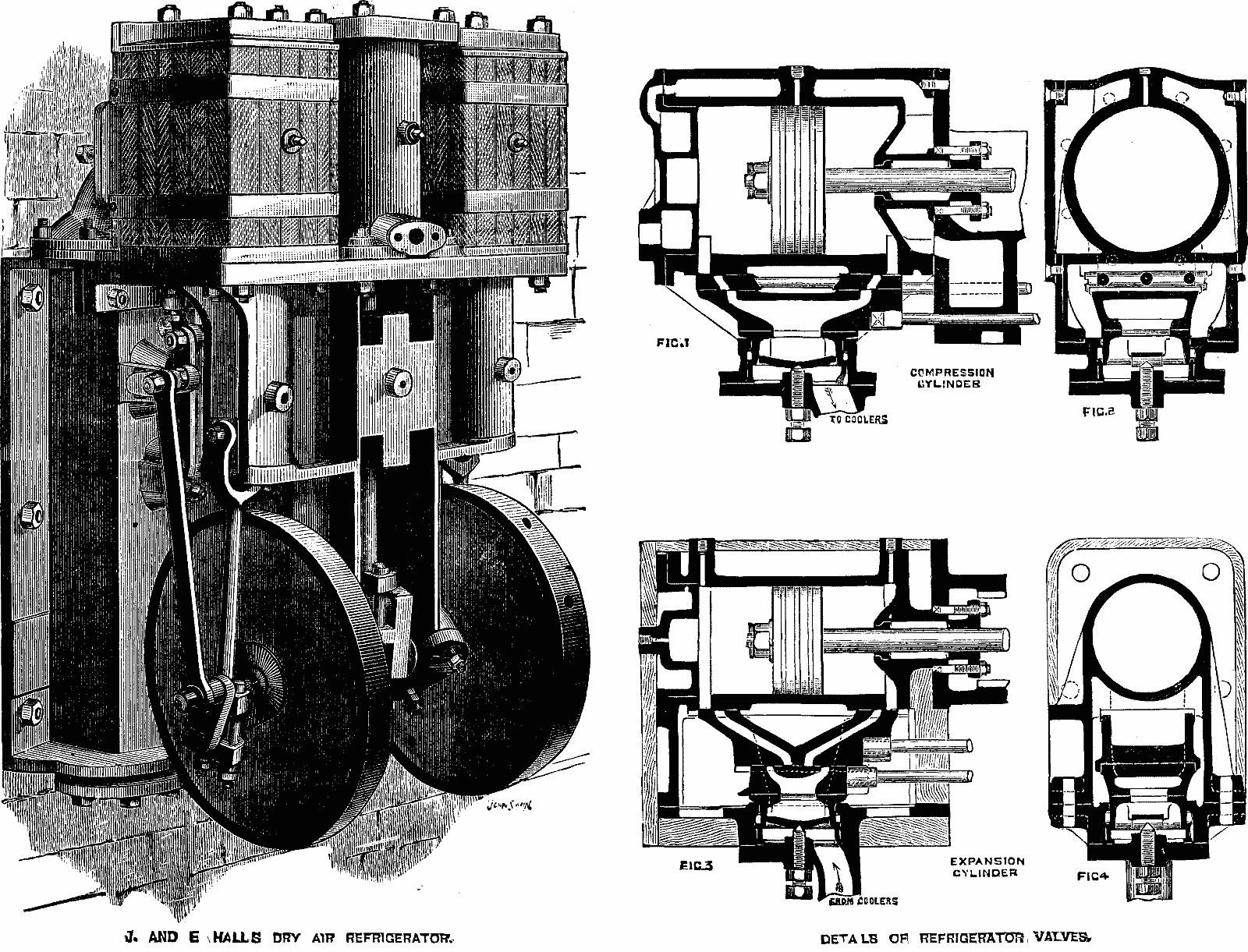
IMPROVED AIR REFRIGERATING MACHINE.
Messrs. J. & E. Hall, Dartford, exhibit at the International Health Exhibition, London, in connection with a cold storage room, two sizes of Ellis' patent air refrigerator, the larger one capable of delivering 5,000 cubic feet of cold air per hour, when running at a speed of 150 revolutions per minute; and the smaller one 2,000 cubic feet of cold air per hour, at 225 revolutions per minute. The special features in these machines are the arrangement of parts, by which great compactness is secured, and the adoption of flat slides for the compressor, instead of the ordinary beat valves, which permits of a high rate of revolution without the objectionable noise which is caused by clacks beating on their seats. The engraving shows the general arrangement of the apparatus. Figs. 1 to 4 show details of the compression and expansion valves, which are ordinary flat slides, partly balanced, and held up to their faces by strong springs from behind. The steam, compression, and expansion cylinders are severally bolted to the end of a strong frame, which though attached to the cooler box does not form part of it, the object being to meet the strains between the cylinders and shaft in as direct a manner as possible without allowing them to act on the cooler casting. Each cylinder is double acting, the pistons being coupled to the shaft by three connecting rods, the two outer ones working upon crank pins fixed to overhung disks, and the center one on a crank formed in the shaft. The slide valves for all the cylinders are driven from two weigh shafts, the main valve shaft being actuated by a follow crank, and the expansion and cut off valves from the crosshead pin of the compressor. The machines may be used either in the vertical position as exhibited, or may be fixed horizontally; and it is stated that the construction is such as to admit of speeds of 200 and 300 revolutions per minute respectively for the larger and smaller machines, under which conditions the delivery of cold air may be taken at about 7,000 and 2,600 cubic feet per hour. Messrs. Hall also make this class of refrigerator without the steam cylinder, and arranged to be driven by a belt from a gas engine or any existing motive power.
Messrs. J. & E. Hall from Dartford are showcasing their cold storage room at the International Health Exhibition in London, featuring two sizes of Ellis' patented air refrigerator. The larger unit can produce 5,000 cubic feet of cold air per hour at a speed of 150 revolutions per minute, while the smaller one can deliver 2,000 cubic feet of cold air per hour at 225 revolutions per minute. The standout features of these machines include their compact design and the use of flat slides for the compressor instead of standard beat valves, which allows for a high speed without the disruptive noise caused by clacks hitting their seats. The engraving illustrates the overall setup of the equipment. Figures 1 to 4 highlight the details of the compression and expansion valves, which utilize ordinary flat slides that are partially balanced and held in place by strong springs from behind. The steam, compression, and expansion cylinders are each bolted to a sturdy frame that, while connected to the cooler box, does not actually form part of it. This design aims to directly address the stresses between the cylinders and the shaft without letting them affect the cooler casting. Each cylinder operates in a double-acting manner, with the pistons linked to the shaft through three connecting rods; the two outer rods work on crank pins fixed to overhung disks, while the center rod operates on a crank attached to the shaft. The slide valves for all cylinders are driven by two weigh shafts, with the main valve shaft activated by a follow crank, and the expansion and cut-off valves operated from the crosshead pin of the compressor. The machines can be set up vertically as displayed or mounted horizontally, and it’s reported that they can reach speeds of 200 and 300 revolutions per minute for the larger and smaller machines, respectively, delivering cold air at approximately 7,000 and 2,600 cubic feet per hour. Messrs. Hall also produces this type of refrigerator without the steam cylinder, which can be driven by a belt from a gas engine or any other existing power source.
A GAS RADIATOR AND HEATER.
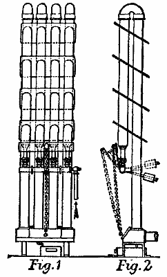
A GAS RADIATOR AND HEATER.
There is now being introduced into Germany a gas radiator and heater, the invention of Herr Wobbe. It consists, as will be seen in engraving above, of a series of vertical U-shaped pipes, of wrought iron, 50 millimeters (2 inches) in diameter. The two legs of the U are of unequal length; the longer being about 5 feet, and the shorter 3 feet (exclusive of the bend at the top). Beneath the open end of the shorter leg of each pipe is placed a burner, attached to a horizontal gas-pipe, which turns upon an axis. The object of having this pipe rotate is to bring the burners into an inclined position—shown by the dotted lines in Fig. 2—for lighting them. On turning them back to the vertical position, the heated products of combustion pass up the shorter tube and down the longer, where they enter a common receptacle, from which they pass into the chimney or out of doors. Surrounding the pipes are plates of sheet iron, inclined at the angle shown in Fig. 2. The object of the plates is to prevent the heated air of the room from passing up to the ceiling, and send it out into the room. To prevent any of the pipes acting as chimneys, and bringing the products of combustion back into the room, as well as to avoid any back-pressure, a damper is attached to the outlet receptacle. The heated gas becomes cooled so much (to about 100° Fahr.) that water is condensed and precipitated, and collects in the vessel below the outlet. Each burner has a separate cock, by which it may be kept closed, half-open, or open. To obviate danger of explosion, there is a strip of sheet iron in front of the burners, which prevents their being lighted when in a vertical position; so that, in case any unburned gas gets into the pipes, it cannot be ignited, for the burners can only be lighted when inclined to the front. In starting the stove the burners are lighted, in the inclined position; the chain from the damper pulled up; the burners set vertical; and, as soon as they are all drawing well into the tubes, the damper is closed. If less heat is desired, the cocks are turned half off. It is not permissible to entirely extinguish some of the burners, unless the unused pipes are closed to prevent the products of combustion coming back into the room. The consumption of gas per burner, full open, with a pressure of 8/10, is said to be only 4-3/8 cubic feet per hour.
There is now a gas radiator and heater being introduced in Germany, invented by Herr Wobbe. As shown in the engraving above, it consists of a series of vertical U-shaped pipes made of wrought iron, each 50 millimeters (2 inches) in diameter. The two legs of the U are not the same length; the longer leg is about 5 feet, and the shorter leg is 3 feet (excluding the bend at the top). Below the open end of the shorter leg of each pipe, there’s a burner attached to a horizontal gas pipe that can rotate around an axis. This rotating pipe is designed to tilt the burners into an inclined position—indicated by the dotted lines in Fig. 2—for lighting. When the burners are turned back to a vertical position, the heated combustion gases rise up the shorter tube and down the longer one, where they enter a common receptacle that leads to the chimney or outside. Surrounding the pipes are sheet iron plates, angled as shown in Fig. 2. These plates are meant to keep the heated air from rising to the ceiling and disperse it throughout the room. To stop any of the pipes from acting like chimneys and bringing combustion gases back indoors, as well as to prevent any back-pressure, a damper is attached to the outlet receptacle. The heated gas cools down significantly (to about 100° Fahrenheit), causing water to condense and collect in a vessel below the outlet. Each burner has its own control valve, allowing it to be turned off, partially open, or fully open. To minimize the risk of explosion, a strip of sheet iron is placed in front of the burners, preventing them from being lit when in a vertical position; this way, any unburned gas in the pipes cannot ignite since the burners can only be lit when tilted forward. To start the stove, the burners are lit in the inclined position, the chain from the damper is pulled up, the burners are set vertical, and once all are drawing well into the tubes, the damper is closed. If less heat is needed, the valves can be turned halfway off. It’s not allowed to fully extinguish some of the burners unless the unused pipes are closed to stop the combustion products from coming back into the room. The gas consumption per burner, when fully open and at a pressure of 8/10, is reported to be only 4-3/8 cubic feet per hour.
CONCRETE WATER PIPES.
Concrete water pipes of small diameter, according to a foreign contemporary, are used in parts of France, notably for water mains for the towns of Coulommiers and Aix-en-Provence. The pipes were formed of concrete in the trench itself. The mould into which the concrete was stamped was sheet iron about two yards in length. The several pipes were not specially joined to each other, the joints being set with mortar. The concrete consisted of three parts of slow setting cement and three parts of river sand, mixed with five parts of limestone debris. The inner diameter of the pipes was nine inches; their thickness, three inches. The average fall is given at one in five hundred; the lowest speed of the current at one foot nine inches per second. To facilitate the cleaning of the pipes, man-holes are constructed every one hundred yards or so, the sides of which are also made of concrete. The trenches are about five feet deep. The work was done by four men, who laid down nearly two hundred feet of pipe in a working day; the cost was about ninety-three cents per running yard. It is claimed as an advantage for the new method that the pipes adhere closely to the inequalities of the trench, and thus lie firmly on the ground. When submitted to great pressure, however, they have not proved effective, and the method, consequently, is only suitable for pipes in which there is no pressure, or only a very trifling one.
Concrete water pipes of small diameter, according to a contemporary overseas source, are used in some areas of France, especially for water mains in the towns of Coulommiers and Aix-en-Provence. The pipes are formed of concrete directly in the trench. The mold for the concrete is made from sheet iron and is about two yards long. The pipes are not specially joined together; the joints are secured with mortar. The concrete mixture consists of three parts slow-setting cement and three parts river sand, blended with five parts limestone scrap. The inner diameter of the pipes is nine inches, and their thickness is three inches. The average slope is one in five hundred, with the lowest speed of the current at one foot nine inches per second. To make cleaning the pipes easier, manholes are built approximately every one hundred yards, with sides also made of concrete. The trenches are around five feet deep. Four workers completed nearly two hundred feet of pipe in a single working day, with a cost of about ninety-three cents per running yard. One advantage of this new method is that the pipes closely conform to the irregularities of the trench, allowing them to rest securely on the ground. However, they have not been effective under high pressure, meaning the method is only suitable for pipes with no pressure or minimal pressure.
THE SELLERS STANDARD SYSTEM OF SCREW THREADS, NUTS, AND BOLT HEADS.
| SCREW THREADS. | NUTS. | BOLT HEADS. | ||||||||||||||||||||||||||||||
|---|---|---|---|---|---|---|---|---|---|---|---|---|---|---|---|---|---|---|---|---|---|---|---|---|---|---|---|---|---|---|---|---|
| Diam. of Screw.  |
Threads per inch.  |
Diameter at root of Thread.  |
Area of Bolt at root of Thread. |
Width of Flat.  |
Short Diam. Rough  |
Short Diam. Finish.  |
Long Diam. Rough.  |
Long Diam. Rough.  |
Thick ness Rough.  |
Thick ness Finish  |
Short Diam. Rough |
Short Diam. Finish. |
Long Diam. Rough. |
Long Diam. Rough. |
Thick ness Rough. |
Thick ness Finish |
||||||||||||||||
| 1 4 4 | 20 | .185 | 13 64 64 | .026 | .0062 | 1 2 2 | 7 16 16 | 37 64 64 | 7 10 10 | 1 4 4 | 3 16 16 |
1 2 2 | 7 16 16 | 37 64 64 | 7 10 10 | 1 4 4 | 3 16 16 |
|||||||||||||||
| 5 16 16 | 18 | .240 | 15 64 64 | .045 | .0074 | 19 32 32 | 17 32 32 | 11 16 16 | 10 12 12 | 5 16 16 | 1 4 4 |
19 32 32 | 17 32 32 | 11 16 16 | 10 12 12 | 19 64 64 | 1 4 4 |
|||||||||||||||
| 3 8 8 | 16 | .294 | 19 64 64 | .067 | .0078 | 11 16 16 | 5 8 8 | 51 64 64 | 63 64 64 | 3 8 8 | 5 16 16 |
11 16 16 | 5 8 8 | 51 64 64 | 63 64 64 | 11 32 32 | 5 16 16 |
|||||||||||||||
| 7 16 16 | 14 | .344 | 11 32 32 | .092 | .0089 | 25 32 32 | 23 33 33 | 9 10 10 | 1 | 7 64 64 | 7 16 16 | 3 8 8 |
25 32 32 | 23 32 32 | 9 16 16 | 1 | 7 64 64 | 25 64 64 | 3 8 8 |
|||||||||||||
| 1 2 2 | 13 | .400 | 13 32 32 | .125 | .0096 | 7 8 8 | 13 16 16 | 1 | 1 | 15 64 64 | 1 2 2 | 7 16 16 |
7 8 8 | 13 16 16 | 1 | 1 | 15 64 64 | 7 16 16 | 7 16 16 |
|||||||||||||
| 9 16 16 | 12 | .454 | 29 64 64 | .161 | .0104 | 31 32 32 | 29 32 32 | 1 | 1 8 8 | 1 | 23 64 64 | 9 16 16 | 1 2 2 |
31 32 32 | 29 32 32 | 1 | 1 8 8 | 1 | 23 64 64 | 31 64 64 | 1 2 2 |
|||||||||||
| 5 8 8 | 11 | .507 | 33 64 64 | .201 | .0113 | 1 | 1 16 16 | 1 | 1 | 7 32 32 | 1 | 1 2 2 | 5 8 8 | 9 16 16 |
1 | 1 16 16 | 1 | 1 | 7 32 32 | 1 | 1 2 2 | 17 32 32 | 9 16 16 |
|||||||||
| 3 4 4 | 10 | .620 | 5 8 8 | .301 | .0125 | 1 | 1 4 4 | 1 | 3 16 16 | 1 | 7 16 16 | 1 | 49 64 64 | 3 4 4 | 11 16 16 |
1 | 1 4 4 | 1 | 3 16 16 | 1 | 7 16 16 | 1 | 49 64 64 | 5 8 8 | 11 16 16 |
|||||||
| 7 8 8 | 9 | .731 | 47 64 64 | .419 | .0138 | 1 | 7 16 16 | 1 | 3 8 8 | 1 | 21 32 32 | 2 | 1 32 32 | 7 8 8 | 13 16 16 |
1 | 7 16 16 | 1 | 3 8 8 | 1 | 21 32 32 | 2 | 1 32 32 | 23 32 32 | 13 16 16 |
|||||||
| 1 | 8 | .837 | 27 32 32 | .550 | .0156 | 1 | 5 8 8 | 1 | 9 16 16 | 1 | 7 8 8 | 2 | 19 64 64 | 1 | 15 16 16 |
1 | 5 8 8 | 1 | 9 16 16 | 1 | 7 8 8 | 2 | 19 64 64 | 13 16 16 | 15 16 16 |
|||||||
| 1 | 1 8 8 | 7 | .940 | 15 16 16 | .693 | .0178 | 1 | 13 16 16 | 1 | 3 4 4 | 2 | 5 32 32 | 2 | 9 16 16 | 1 | 1 8 8 | 1 | 1 16 16 |
1 | 13 16 16 | 1 | 3 4 4 | 2 | 5 32 32 | 2 | 7 16 16 | 29 32 32 | 1 | 1 16 16 |
|||
| 1 | 1 4 4 | 7 | 1.065 | 1 | 1 16 16 | .890 | .0178 | 2 | 1 | 15 16 16 | 2 | 5 16 16 | 2 | 53 64 64 | 1 | 1 4 4 | 1 | 3 16 16 |
2 | 1 | 15 16 16 | 2 | 5 16 16 | 2 | 53 64 64 | 1 | 1 | 3 16 16 |
||||
| 1 | 3 8 8 | 6 | 1.160 | 1 | 5 32 32 | 1.056 | .0208 | 2 | 3 16 16 | 2 | 1 8 8 | 2 | 17 32 32 | 3 | 3 32 32 | 1 | 3 8 8 | 1 | 5 16 16 |
2 | 3 16 16 | 2 | 1 8 8 | 2 | 17 32 32 | 3 | 3 32 32 | 1 | 3 32 32 | 1 | 5 16 16 |
|
| 1 | 1 2 2 | 6 | 1.284 | 1 | 9 32 32 | 1.294 | .0208 | 2 | 3 8 8 | 2 | 5 16 16 | 2 | 3 4 4 | 3 | 23 64 64 | 1 | 1 2 2 | 1 | 7 16 16 |
2 | 3 8 8 | 2 | 5 16 16 | 2 | 3 4 4 | 3 | 23 64 64 | 1 | 3 16 16 | 1 | 7 16 16 |
|
| 1 | 5 8 8 | 5 | 1 2 2 | 1.389 | 1 | 25 64 64 | 1.515 | .0227 | 2 | 9 16 16 | 2 | 1 2 2 | 2 | 31 32 32 | 3 | 5 8 8 | 1 | 5 8 8 | 1 | 9 16 16 |
2 | 9 16 16 | 2 | 1 2 2 | 2 | 31 32 32 | 3 | 5 8 8 | 1 | 9 32 32 | 1 | 9 16 16 |
| 1 | 3 4 4 | 5 | 1.491 | 1 | 31 64 64 | 1.746 | .0250 | 2 | 3 4 4 | 2 | 11 16 16 | 3 | 3 16 16 | 3 | 57 64 64 | 1 | 3 4 4 | 1 | 11 16 16 |
2 | 3 4 4 | 2 | 11 16 16 | 3 | 3 16 16 | 3 | 57 64 64 | 1 | 3 8 8 | 1 | 11 16 16 |
|
| 1 | 7 8 8 | 5 | 1.616 | 1 | 39 64 64 | 2.051 | .0250 | 2 | 15 16 16 | 2 | 7 8 8 | 3 | 13 32 32 | 4 | 5 32 32 | 1 | 7 8 8 | 1 | 13 16 16 |
2 | 15 16 16 | 2 | 7 8 8 | 3 | 13 32 32 | 4 | 5 32 32 | 1 | 15 32 32 | 1 | 13 16 16 |
|
| 2 | 4 | 1 2 2 | 1.742 | 1 | 23 32 32 | 2.301 | .0277 | 3 | 1 8 8 | 3 | 1 16 16 | 3 | 5 8 8 | 4 | 27 64 64 | 2 | 1 | 15 16 16 |
3 | 1 8 8 | 3 | 1 16 16 | 3 | 5 8 8 | 4 | 27 64 64 | 1 | 9 16 16 | 1 | 15 16 16 |
||
| 2 | 1 4 4 | 4 | 1 2 2 | 1.962 | 1 | 31 32 32 | 3.023 | .0277 | 3 | 1 2 2 | 3 | 7 16 16 | 4 | 1 16 16 | 4 | 61 64 64 | 2 | 1 4 4 | 2 | 3 16 16 |
3 | 1 2 2 | 3 | 7 16 16 | 4 | 1 16 16 | 4 | 61 64 64 | 1 | 3 4 4 | 2 | 3 16 16 |
| 2 | 1 2 2 | 4 | 2.176 | 2 | 11 64 64 | 3.718 | .0312 | 3 | 7 8 8 | 3 | 13 16 16 | 4 | 1 2 2 | 5 | 31 64 64 | 2 | 1 2 2 | 2 | 7 16 16 |
3 | 7 8 8 | 3 | 13 16 16 | 4 | 1 2 2 | 5 | 31 64 64 | 1 | 15 16 16 | 2 | 7 16 16 |
|
| 2 | 3 4 4 | 4 | 2.426 | 2 | 27 64 64 | 4.622 | .0312 | 4 | 1 4 4 | 4 | 3 16 16 | 4 | 29 32 32 | 6 | 2 | 3 4 4 | 2 | 11 16 16 |
4 | 1 4 4 | 4 | 3 16 16 | 4 | 29 32 32 | 6 | 2 | 1 8 8 | 2 | 11 16 16 |
|||
| 3 | 3 | 1 2 2 | 2.629 | 2 | 5 8 8 | 5.428 | .0357 | 4 | 5 8 8 | 4 | 9 16 16 | 5 | 3 8 8 | 6 | 17 32 32 | 3 | 2 | 15 16 16 |
4 | 5 8 8 | 4 | 9 16 16 | 5 | 3 8 8 | 6 | 17 32 32 | 2 | 5 16 16 | 2 | 15 16 16 |
||
| 3 | 1 4 4 | 3 | 1 2 2 | 2.879 | 2 | 7 8 8 | 6.509 | .0357 | 5 | 4 | 15 16 16 | 5 | 13 16 16 | 7 | 1 16 16 | 3 | 1 4 4 | 3 | 3 16 16 |
5 | 4 | 15 16 16 | 5 | 13 16 16 | 7 | 1 16 16 | 2 | 1 2 2 | 3 | 3 16 16 |
||
| 3 | 1 2 2 | 3 | 1 4 4 | 3.100 | 3 | 3 32 32 | 7.547 | .0384 | 5 | 3 8 8 | 5 | 5 16 16 | 6 | 7 32 32 | 7 | 39 64 64 | 3 | 1 2 2 | 3 | 7 16 16 |
5 | 3 8 8 | 5 | 5 16 16 | 6 | 7 32 32 | 7 | 39 64 64 | 2 | 11 16 16 | 3 | 7 16 16 |
| 3 | 3 4 4 | 3 | 3.317 | 3 | 5 16 16 | 8.614 | .0413 | 5 | 3 4 4 | 5 | 11 16 16 | 6 | 21 32 32 | 8 | 1 8 8 | 3 | 3 4 4 | 3 | 11 16 16 |
5 | 3 4 4 | 5 | 11 16 16 | 6 | 21 32 32 | 8 | 1 8 8 | 2 | 7 8 8 | 3 | 11 16 16 |
|
| 4 | 3 | 3.567 | 3 | 9 16 16 | 9.993 | .0413 | 6 | 1 8 8 | 6 | 1 16 16 | 7 | 3 32 32 | 8 | 41 64 64 | 4 | 3 | 15 16 16 |
6 | 1 8 8 | 6 | 1 16 16 | 7 | 3 32 32 | 8 | 41 64 64 | 3 | 1 16 16 | 3 | 15 16 16 |
|||
| 4 | 1 4 4 | 2 | 7 8 8 | 3.798 | 3 | 51 64 64 | 11.329 | .0435 | 6 | 1 2 2 | 6 | 7 16 16 | 7 | 9 16 16 | 9 | 3 16 16 | 4 | 1 4 4 | 4 | 3 16 16 |
6 | 1 2 2 | 6 | 7 16 16 | 7 | 9 16 16 | 9 | 3 16 16 | 3 | 1 4 4 | 4 | 3 16 16 |
| 4 | 1 2 2 | 2 | 3 4 4 | 4.028 | 4 | 1 32 32 | 12.742 | .0454 | 6 | 7 8 8 | 6 | 13 16 16 | 7 | 31 32 32 | 9 | 3 4 4 | 4 | 1 2 2 | 4 | 7 16 16 |
6 | 7 8 8 | 6 | 13 16 16 | 7 | 31 32 32 | 9 | 3 4 4 | 3 | 7 16 16 | 4 | 7 16 16 |
| 4 | 3 4 4 | 2 | 5 8 8 | 4.256 | 4 | 1 4 4 | 14.226 | .0476 | 7 | 1 4 4 | 7 | 3 16 16 | 8 | 13 32 32 | 10 | 1 4 4 | 4 | 3 4 4 | 4 | 11 16 16 |
7 | 1 4 4 | 7 | 3 16 16 | 8 | 13 32 32 | 10 | 1 4 4 | 3 | 5 8 8 | 4 | 11 16 16 |
| 5 | 2 | 1 2 2 | 4.480 | 4 | 31 64 64 | 15.763 | .0500 | 7 | 5 8 8 | 7 | 9 16 16 | 8 | 27 32 32 | 10 | 49 64 64 | 5 | 4 | 15 16 16 |
7 | 5 8 8 | 7 | 9 16 16 | 8 | 27 32 32 | 10 | 49 64 64 | 3 | 13 16 16 | 4 | 15 16 16 |
||
| 5 | 1 4 4 | 2 | 1 2 2 | 4.730 | 4 | 47 64 64 | 17.570 | .0500 | 8 | 7 | 15 16 16 | 9 | 9 32 32 | 11 | 23 64 64 | 5 | 1 4 4 | 5 | 3 16 16 |
8 | 7 | 15 16 16 | 9 | 9 32 32 | 11 | 23 64 64 | 4 | 5 | 3 16 16 |
|||
| 5 | 1 2 2 | 2 | 3 8 8 | 4.953 | 4 | 61 64 64 | 19.267 | .0526 | 8 | 3 8 8 | 8 | 5 16 16 | 9 | 23 32 32 | 11 | 7 8 8 | 5 | 1 2 2 | 5 | 7 16 16 |
8 | 3 8 8 | 8 | 5 16 16 | 9 | 23 32 32 | 11 | 7 8 8 | 4 | 3 16 16 | 5 | 7 16 16 |
| 5 | 3 4 4 | 2 | 3 8 8 | 5.203 | 5 | 13 64 64 | 21.261 | .0526 | 8 | 3 4 4 | 8 | 11 16 16 | 10 | 5 32 32 | 12 | 5 | 3 4 4 | 5 | 11 16 16 |
8 | 3 4 4 | 8 | 11 16 16 | 10 | 5 32 32 | 12 | 3 8 8 | 4 | 3 8 8 | 5 | 11 16 16 |
|
| 6 | 2 | 1 4 4 | 5.423 | 5 | 27 64 64 | 23.097 | .0555 | 9 | 1 8 8 | 9 | 1 16 16 | 10 | 19 32 32 | 12 | 15 16 16 | 6 | 5 | 15 16 16 |
9 | 1 8 8 | 9 | 1 16 16 | 10 | 19 32 32 | 12 | 15 16 16 | 4 | 9 16 16 | 5 | 15 16 16 |
||
The dimensions given for diameter at root of threads are also those for diameter of hole in nuts and diameter of lap drills. All bolts and studs 3/4 in. diameter and above, screwed into boilers, have 12 threads per inch, sharp thread, a taper of 1/16 in. per 1 inch; tap drill should be 9/64 in. less than normal diameter of bolts.
The dimensions provided for the diameter at the base of the threads are also applicable to the diameter of holes in nuts and the diameter of lap drills. All bolts and studs that are 3/4 inches in diameter and larger, which are screwed into boilers, have 12 threads per inch, a sharp thread, and a taper of 1/16 inch for every 1 inch. The tap drill should be 9/64 inch less than the standard diameter of the bolts.
The table is based upon the following general formulæ for certain dimensions:
The table is based on the following general formulas for specific dimensions:
| Short diam. rough nut or head | = | 11/2 diam. of bolt + 1/8. |
| Short diam. finished nut or head | = | 11/2 diam. of bolt + 1/16. |
| Thickness rough nut | = | diameter of bolt. |
| Thickness finished nut | = | diameter of bolt - 1/16. |
| Thickness rough head | = | 1/2 short diameter. |
| Thickness finished head | = | diameter of bolt - 1/16. |
AN ENGLISH RAILWAY FERRY BOAT.

AN ENGLISH RAILWAY FERRY BOAT.
The illustrations above represent a double screw steam ferry boat for transporting railway carriages, vehicles, and passengers, etc., designed and constructed by Messrs. Edwards and Symes, of Cubitt Town, London. The hull is constructed of iron, and is of the following dimensions: Length 60 ft.; beam 16 ft.; over sponsons 25 ft. The vessel was fitted with a propeller, rudder, and steering gear at each end, to enable it to run in either direction without having to turn around. The boat was designed for the purpose of working the train service across the bay of San Juan, in the island of Puerto Rico, and for this purpose a single line of steel rails, of meter gauge, is laid along the center of the deck, and also along the hinged platforms at each end. In the engraving these platforms are shown, one hoisted up, and the other lowered to the level of the deck. When the boat is at one of the landing stages, the platform is lowered to the level of the rails on the pier, and the carriages and trucks are run on to the deck by means of the small hauling engine, which works an endless chain running the whole length of the deck. The trucks, etc., being on board, the platform is raised by means of two compact hand winches worked by worm and worm-wheels in the positions shown; thus these two platforms form the end bulwarks to the boat when crossing the bay. On arriving at the opposite shore the operation is repeated, the other platform is lowered, and the hauling engine runs the trucks, etc., on to the shore. With a load of 25 tons the draught is 4 ft.
The illustrations above show a double screw steam ferry boat designed to transport railway carriages, vehicles, and passengers, created by Messrs. Edwards and Symes of Cubitt Town, London. The hull is made of iron and has the following dimensions: Length 60 ft.; beam 16 ft.; over sponsons 25 ft. The vessel is equipped with a propeller, rudder, and steering gear at both ends, allowing it to operate in either direction without needing to turn around. The boat is intended to operate the train service across San Juan Bay in Puerto Rico, and for this, a single line of steel rails with a meter gauge is laid along the center of the deck and the hinged platforms at each end. In the engraving, these platforms are depicted, one raised and the other lowered to the level of the deck. When the boat is at a landing stage, the platform is lowered to align with the rails on the pier, and the carriages and trucks are rolled onto the deck using a small hauling engine that operates an endless chain along the deck's length. Once the trucks are on board, the platform is raised using two compact hand winches driven by worm and worm-wheels as shown; this way, the two platforms serve as end bulwarks for the boat while crossing the bay. Upon reaching the opposite shore, the process is reversed: the other platform is lowered and the hauling engine pulls the trucks onto the shore. The draught with a load of 25 tons is 4 ft.
The seats shown on the deck are for the convenience of foot passengers, and the whole of the deck is protected from the sun of that tropical climate by a canvas awning. The steering of the vessel is effected from the bridge at the center, which extends from side to side of the vessel, and there are two steering wheels with independent steering gear for each end, with locking gear for the forward rudder when in motion. The man at the wheel communicates with the engineer by means of a speaking tube at the wheel. There is a small deck house for the use of deck stores, on one side of which is the entrance to the engine room. The cross battens, shown between the rails, are for the purpose of horse traffic, when horses are used for hauling the trucks, or for ordinary carts or wagons. The plan below deck shows the arrangement of the bulkheads, with a small windlass at each end for lifting the anchors, and a small hatch at each side for entrance to these compartments. The central compartment contains the machinery, which consists of a pair of compound surface condensing engines, with cylinders 11 in. and 20 in. in diameter; the shafting running the whole length of the vessel, with a propeller at each end. Steam is generated in a steel boiler of locomotive form, so arranged that the funnel passes through the deck at the side of the vessel; and it is designed for a working pressure of 100 lb. per square inch. This boiler also supplies steam for the small hauling engine fixed on the bulkhead. Light to this compartment is obtained by means of large side scuttles along each side of the boat and glass deck lights, and the iron grating at the entrance near the deck house. This boat was constructed in six pieces for shipment, and the whole put together in the builders' yard. The machinery was fixed, and the engine driven by steam from its own boiler, then the whole was marked and taken asunder, and shipped to the West Indies, where it was put together and found to answer the purpose intended.—Engineering.
The seats on the deck are meant for the convenience of foot passengers, and the entire deck is protected from the sun of that tropical climate by a canvas awning. The vessel's steering is done from the bridge in the center, which stretches across the vessel, and there are two steering wheels with separate steering gear for each end, along with a locking mechanism for the forward rudder when in motion. The person at the wheel communicates with the engineer through a speaking tube located at the wheel. There’s a small deck house for storing deck supplies, with an entrance to the engine room on one side. The cross battens shown between the rails are used for horse traffic when horses are hauling the trucks, or for regular carts or wagons. The layout below deck illustrates the arrangement of the bulkheads, with a small windlass at each end for lifting the anchors, and a small hatch on each side for accessing these compartments. The central compartment houses the machinery, which includes a pair of compound surface condensing engines with cylinders 11 in. and 20 in. in diameter; the shafting runs the entire length of the vessel, with a propeller at each end. Steam is generated in a locomotive-style steel boiler, designed such that the funnel passes through the deck at the side of the vessel, and it’s built to handle a working pressure of 100 lb. per square inch. This boiler also supplies steam for the small hauling engine mounted on the bulkhead. Light in this compartment comes from large side scuttles along each side of the boat, glass deck lights, and an iron grating at the entrance near the deck house. The boat was constructed in six pieces for shipping and was fully assembled in the builder's yard. The machinery was installed, and the engine was powered by steam from its own boiler, then everything was marked, taken apart, and shipped to the West Indies, where it was reassembled and proved to be effective for its intended purpose.—Engineering.
THE PROBLEM OF FLIGHT, AND THE FLYING MACHINE.
As a result of reading the various communications to the Scientific American and Supplement, and Van Nostrand's Engineering Magazine, including descriptions of proposed and tested machines, and the reports of the British Aeronautical Society, the writer of the following concludes:
As a result of reading the different articles in Sci American and Addendum, along with Van Nostrand's Engineering Magazine, which included descriptions of suggested and experimented machines, as well as the reports from the British Aeronautical Society, the author of the following concludes:
That, as precedents for the construction of a successful flying machine, the investigation of some species of birds as a base of the principles of all is correct only in connection with the species and habits of the bird; that the general mechanical principles of flight applicable to the operation of the same unit of wing in all species are alone applicable to the flying machine.
That looking at certain bird species to learn how to build a successful flying machine is valid only when considering the specific species and their behaviors; that the general mechanical principles of flight that apply to the operation of the same unit of wing in all species are the only ones that can be applied to the flying machine.
That these principles of operation do not demand the principles of construction of the bird.
That these principles of operation do not require the principles of construction of the bird.
That as the wing is in its stroke an arc of a screw propeller's operation, and in its angle a screw propeller blade, its animal operation compels its reciprocation instead of rotation.
That as the wing moves in an arc like a screw propeller's operation, and in its angle resembles a screw propeller blade, its function in animals causes it to move back and forth instead of rotating.
That the swifter the wing beat, the more efficient its effect per unit of surface, the greater the load carried, and the swifter the flight.
That the faster the wing beats, the more effective it is per unit of surface area, the heavier the load it can carry, and the quicker the flight.
That the screw action being, in full flight, that of a screw propeller whose axis of rotation forms a slight angle with the vertical, the distance of flight per virtual "revolution" of "screw" wing far exceeds the pitch distance of said "screw."
That the screw action, when fully engaged, is like that of a screw propeller whose axis of rotation is angled slightly from the vertical, the distance traveled per virtual "revolution" of the "screw" wing greatly exceeds the pitch distance of that "screw."
That consequently a bird's flight answers to an iceboat close hauled; the wing force answering to the wind, the wing angle to the sail, the bird's weight to the leeway fulcrum of the ice, and the passage across direction of the wing flop to the fresh moving "inertia" of the wind, both yielding a maximum of force to bird or iceboat.
That means a bird's flight is similar to an iceboat sailing close to the wind; the wing force corresponds to the wind, the wing angle relates to the sail, the bird's weight is like the leeway fulcrum of the ice, and the direction of the wing flap moving across the wind's fresh inertia both generate maximum force for the bird or the iceboat.
That the speed of reciprocation of a fly's wing being equivalent to a screw rotation of 9,000 per minute, proves that a screw may be run at this speed without losing efficiency by centrifugal vacuum.
That the speed of a fly's wing moving back and forth is like a screw rotating at 9,000 times per minute shows that a screw can operate at this speed without losing efficiency due to centrifugal force.
That as the object of wing or screw is to mount upon the inertia of the particles of a mobile fluid, and as the rotation of steamship propellers in water—a fluid of many times the inertia of air—is already in excess of the highest speed heretofore tried in the propellers of moderately successful flying machines, it is plain that the speed employed in water must be many times exceeded in air.
That just as the object of a wing or screw is to rely on the inertia of the particles in a moving fluid, and as the rotation of steamship propellers in water—a fluid that has much greater inertia than air—is already operating at higher speeds than those previously used in the propellers of moderately successful flying machines, it's clear that the speed needed in air must be significantly greater than in water.
That with a sufficient speed of rotation, the supporting power of the inertia of air must equal that of water.
That with a sufficient speed of rotation, the supporting power of the inertia of air must equal that of water.
That as mere speed of rotation of propeller shaft, minus blades, must absorb but a small proportion of power of engine, the addition of blades will not cause more resistance than that actually encountered from inertia of air.
That the mere speed of rotation of the propeller shaft, without the blades, must take up only a small amount of the engine's power. The addition of blades won't create more resistance than what is actually faced from the air's inertia.
That this must be the measure of load lifted.
That this must be the standard for the amount of load lifted.
That without slip of screw, the actual power expended, will be little in excess of that required to support the machine in water, with a slower rotation of screw.
That without slip of screw, the actual power used will be only slightly more than what’s needed to keep the machine afloat in water, with a slower rotation of screw.
That in case the same power is expended in water or air, the only difference will lie in the sizes and speed of engines or screws.
That if the same power is used in water or air, the only difference will be in the sizes and speeds of the engines or propellers.
That the greater the speed, the less weight of engine, boiler, and screw must be, and the stronger their construction.
That the greater the speed, the less weight of engine, boiler, and screw must be, and the stronger their construction.
That, in consequence, solid metal worked down, instead of bolts and truss work, must be used.
That means we need to use solid metal instead of bolts and truss work.
That as the bird wing is a screw in action, and acts directly between the inertias of the load and the air, the position and operation of the screw, to the load, must imitate it.
That as the bird's wing is like a screw in action and works directly between the weights of the load and the air, the position and function of the screw, in relation to the load, must reflect this.
That, in consequence, machines having wing planes, driven against one inertia of air by screws acting in the line, of flight against another inertia of air, lose fifty per cent. of useful effect, besides exposing to a head wind the cross section of the stationary screw wing planes and the rotating screw discs; and supporting the dead weight of the wing planes, and having all the screw slip in the line of flight, and carrying slow and heavy engines.
That means machines with wings, driven against one inertia of air by screws that work in the direction of flight against another inertia of air, lose fifty percent of their useful effect. This also exposes the stationary wing planes and the rotating screw discs to a headwind. Additionally, they have to carry the weight of the wing planes, deal with all the screw slip in the direction of flight, and use slow, heavy engines.
That as a result of these conclusions, the supporting and propelling power should be expressed in the rotation of screws combining both functions, the position of whose planes of rotation to a fixed horizontal line of direction determines the progress and speed of machine upon other lines.
That as a result of these conclusions, the supporting and driving force should be shown in the rotation of screws that combine both functions, with the angle of their rotation planes relative to a fixed horizontal direction determining the machine's progress and speed on other lines.
That the whole weight carried by the screws should be at all times exactly below the center of gravity of the plane of support, whether it be horizontal or inclined.
That the entire weight supported by the screws should always be directly beneath the center of gravity of the support plane, whether it's horizontal or sloped.
That while the permanently positioned weight, such as the engines, frame, holding screws, etc., may be rigidly connected to or around the screw plane of support, the variable positioned weight, such as the passenger and the car, should be connected by a flexible joint to the said plane of support.
That while the permanently placed weight, like the engines, frame, holding screws, etc., may be firmly attached to or around the support screw plane, the weight that changes position, such as the passengers and the car, should be connected by a flexible joint to the support plane.
Consequently, the car may oscillate without altering its weight position under center of supporting plane, thus avoiding an involuntary alteration of speed or direction of flight.
Consequently, the car can move back and forth without changing its weight distribution over the middle of the support surface, thus preventing any unintentional change in speed or direction of travel.
That the reservoir of power, the boiler, etc., should be placed in the car, and steam carried to engines through joint connecting car with machine.
That the power source, the boiler, etc., should be installed in the car, and steam transported to the engines through a joint connection between the car and the machine.
That at present material exists, and power also, of sufficient lightness and strength to admit of a machine construction capable of a limited successful flight in any fair wind and direction.
That right now, there are materials that are light and strong enough to build a machine that can make limited successful flights in any good wind and direction.
That such machine once built, the finding of a power for long flights will be easy, if not already close at hand in electricity.
That once this machine is built, finding a power for long flights will be easy, if it's not already within reach with electricity.
That the easiest design for such actual machine should be adopted, leaving the adaptation of the principles involved to the making of more perfect machines, to a time after the success of the first.
That the easiest design for such an actual machine should be chosen, allowing the principles involved to be refined in the creation of more advanced machines, at a later time after the success of the first.
That such design may be a propeller, and its engine at each end of a steel frame tube, supporting tube horizontally, a car to be supported by a universal joint from center of said tube, and the joint apparatus movable along the tube or a short distance transverse to it, to alter position of center of gravity.
That design could function as a propeller, with its engine at both ends of a steel frame tube. The tube would be positioned horizontally, and a car would be supported by a universal joint at the center of the tube. The joint apparatus would be adjustable along the tube or a short distance across it, allowing for changes in the center of gravity.
That the machine so built might traverse the water as well as air.
That the machine built this way could travel on both water and air.
THE LONGHAIRED POINTER MYLORD.
Pointers are trained to search for game, and to indicate that they have found the same by standing motionless in front of it, and, when it has been shot, to carry the game to the huntsman. Several kinds of pointers are known, such as smooth, longhaired, and bushyhaired pointers. The smoothhaired pointers are better for hunting on high land, whereas the longhaired or bushyhaired dogs are better for low, marshy countries, crossed by numerous streams, etc. Mylord, the dog represented in the annexed cut taken from the Illustrirte Zeitung, is an excellent specimen of the longhaired pointer, and is owned by Mr. G. Borcher, of Braunschweig, Germany.
Pointers are trained to search for game and signal that they’ve found something by standing still in front of it. After the game is shot, they bring it back to the hunter. There are several types of pointers, including smooth, longhaired, and bushyhaired pointers. Smoothhaired pointers are better for hunting in high areas, while longhaired or bushyhaired dogs are more suitable for low, marshy regions with many streams. Mylord, the dog shown in the attached image from the Illustrirte Zeitung, is an excellent example of a longhaired pointer and belongs to Mr. G. Borcher from Braunschweig, Germany.

THE LONGHAIRED POINTER, "MYLORD."
The longhaired pointer is generally above the medium size, powerful, somewhat longer than the normal dog, the body is narrower and not quite as round as that of the smoothhaired dog, and the muscles of the shoulders and hind legs are not as well developed and not as prominent. The head and neck are erect, the head being specially long, and the tail is almost horizontal to the middle, and then curves upward slightly. The long hair hangs in wavy lines on both sides of his body. The expression of his face is intelligent, bright, and good-natured, and his step is light and almost noiseless.
The longhaired pointer is usually larger than medium size, strong, and somewhat longer than the average dog. Its body is narrower and not as round as that of the smoothhaired dog, and the muscles in the shoulders and hind legs aren't as developed or prominent. The head and neck are upright, with the head being particularly long. The tail is nearly horizontal in the middle and then curves upward slightly. The long hair flows in wavy lines on both sides of its body. The dog's expression is intelligent, lively, and friendly, and its movement is light and almost silent.
The pointer is specially valuable, as it can be employed for many different purposes; he is an excellent dog for the woods, for the woodsman and hunter who uses only one dog for different kinds of game. The intelligence of the German pointer is very great, but he does not develop as rapidly as the English dog, which has been raised for generations for one purpose only. The German pointer hunts very slowly, but surely. It is not difficult to train this dog, but he cannot be trained until he has reached a certain age.
The pointer is especially valuable because it can be used for many different purposes; it's an excellent dog for the outdoorsman and hunter who relies on just one dog for various types of game. The intelligence of the German pointer is quite high, but it doesn't develop as quickly as the English dog, which has been bred for generations for a single purpose. The German pointer hunts slowly, but steadily. It's not hard to train this dog, but it can't be trained until it reaches a certain age.
LUNAR HEAT.
By Professor C.A. YOUNG.
One of the most interesting inquiries relating to the moon is that which deals with the heat she sends us, and the probable temperature of her surface. The problem seems to have been first attacked by Tschirnhausen and La Hire, about 1700; and they both found, that even when the moon's rays were concentrated by the most powerful burning-lenses and mirrors they could obtain, its heat was too small to produce the slightest perceptible effect on the most delicate thermometers then known. For more than a hundred years, this was all that could be made out, though the experiment was often repeated.
One of the most fascinating questions about the moon is related to the heat it sends our way and its likely surface temperature. This problem seems to have been first tackled by Tschirnhausen and La Hire around 1700. They both discovered that even when they used the strongest burning lenses and mirrors available to focus the moon's rays, the heat was still too minimal to register even the slightest effect on the most sensitive thermometers of that time. For over a hundred years, that was all that could be determined, though the experiment was frequently repeated.
It was not until 1831 that Melloni, with his newly-invented "thermopile," 1 succeeded in making the lunar heat sensible; and in 1835, taking his apparatus to the top of Vesuvius, he obtained not only perceptible, but measurable, results, getting a deviation of four or five divisions of his galvanometer.
It wasn't until 1831 that Melloni, with his newly-invented "thermopile," 1 managed to detect lunar heat; and in 1835, by bringing his equipment to the summit of Vesuvius, he achieved not just noticeable, but quantifiable results, recording a deviation of four or five divisions on his galvanometer.
Others repeated the experiment several times between this time and 1856, with more or less success; but, so far as I know, the first quantitative result was that obtained in 1856 by Piazzi Smyth during his Teneriffe expedition. On the top of the mountain, at an elevation of ten thousand feet, he found that the moon's rays affected his thermopile to the same extent as a standard candle ten feet away. Marie Davy has since shown that this corresponds to a heating effect of about 1/1300 of a Centigrade degree.
Others conducted the experiment multiple times between this time and 1856, achieving varying degrees of success; however, as far as I know, the first quantitative result was obtained in 1856 by Piazzi Smyth during his Teneriffe expedition. At the top of the mountain, at an elevation of ten thousand feet, he discovered that the moon's rays affected his thermopile just like a standard candle ten feet away. Marie Davy has since demonstrated that this corresponds to a heating effect of about 1/1300 of a degree Celsius.
The subject was resumed in 1868 by Lord Rosse in Ireland; and a long series of observations, running through several years, was made by the aid of his three-foot reflector (not the great six-foot instrument, which is too unwieldy for such work). The results of his work have, until very recently, been accepted as authoritative. It should be mentioned that, at about the same time, observations were also made at Paris by Marie Davy and Martin; but they are generally looked upon merely as corroborative of Rosse's work, which was more elaborate and extensive. Rosse considered that his results show that the heat from the moon is mainly obscure, radiated heat; the reflected heat, according to him, being much less in amount.
The topic was picked up again in 1868 by Lord Rosse in Ireland, and he conducted a long series of observations over several years using his three-foot reflector (not the large six-foot instrument, which is too bulky for this kind of work). The findings from his research were considered authoritative until very recently. It’s worth noting that around the same time, observations were also carried out in Paris by Marie Davy and Martin; however, their work is generally seen as just supporting Rosse's findings, which were more detailed and comprehensive. Rosse believed that his results indicated that the heat from the moon is primarily obscure, radiated heat, while the reflected heat is considerably less.
A moment's thought will show that the moon's heat must consist of two portions. First, there will be reflected solar heat. The amount and character of this will depend in no way upon the temperature of the moon's surface, but solely upon its reflecting power. And it is to be noted that moon-light is only a part of this reflected radiant energy, differing from the invisible portion of the same merely in having such a wave-length and vibration period as to bring it within the range of perception of the human eye.
A moment's thought will show that the moon's heat must consist of two parts. First, there will be reflected solar heat. The amount and type of this will not depend at all on the temperature of the moon's surface, but only on its ability to reflect light. It's also important to note that moon-light is just a part of this reflected radiant energy, differing from the invisible part only because it has a wave length and vibration period that makes it visible to the human eye.
The second portion of the heat sent us by the moon is that which she emits on her own account as a warm body—warmed, of course, mainly, if not entirely, by the action of the sun. The amount of this heat will depend upon the temperature of the moon's surface and its radiating power; and the temperature will depend upon a number of things (chiefly heat-absorbing power of the surface, and the nature and density of the lunar atmosphere, as well as the supply of heat received from the sun), being determined by a balance between give and take. So long as more heat is received in a second than is thrown off in the same time, the temperature will rise, and vice versa.
The second part of the heat we get from the moon comes from the moon itself as a warm object—mainly heated, if not completely, by the sun's energy. The amount of this heat relies on the temperature of the moon's surface and its ability to radiate heat; and the temperature depends on several factors (primarily the heat-absorbing capacity of the surface, as well as the type and density of the lunar atmosphere, along with the heat it receives from the sun), determined by a balance of incoming and outgoing heat. As long as more heat is received in a second than is lost in the same time frame, the temperature will rise, and vice versa.
It is to be noted, further, that this second component of the moon's thermal radiance must be mainly what is called "obscure" or dark heat, like that from a stove or teakettle, and characterized by the same want of penetrative power. No one knows why at present; but it is a fact that the heat-radiations from bodies at a low temperature—radiations of which the vibrations are relatively slow, and the wave-length great—have no such power of penetrating transparent media as the higher-pitched vibrations which come from incandescent bodies. A great part, therefore, of this contingent of the lunar heat is probably stopped in the upper air, and never reaches the surface of the earth at all.
It should be noted that this second part of the moon's thermal radiation is mainly what we refer to as "obscure" or dark heat, similar to what you feel from a stove or kettle, and it lacks the ability to penetrate well. The reason for this is still unknown; however, it’s a fact that heat radiations from cooler bodies—radiations with slower vibrations and longer wavelengths—do not penetrate transparent materials as effectively as the higher-pitched vibrations from hot bodies. Therefore, a significant portion of this lunar heat likely gets trapped in the upper atmosphere and never actually reaches the Earth's surface.
Now, the thermopile cannot, of course, discriminate directly between the two portions of the lunar heat; but to some extent it does enable us to do so indirectly, since they vary in quite a different way with the moon's age. The simple reflected heat must follow the same law as moonlight, and come to its maximum at full moon. The radiated heat, on the other hand, will reach its maximum when the average temperature of that part of the moon's surface turned toward the earth is highest; and this must be some time after full moon, for the same sort of reasons that make the hottest part of a summer's day come two or three hours after noon.
Now, the thermopile can't directly differentiate between the two types of lunar heat; however, it does allow us to indirectly tell them apart to some extent, since they change differently according to the moon's age. The simple reflected heat must follow the same pattern as moonlight, peaking at full moon. The radiated heat, on the other hand, will hit its peak when the average temperature of the part of the moon's surface facing the earth is highest; and this happens sometime after full moon, for the same reasons that make the hottest part of a summer day occur two or three hours after noon.
The conclusion early reached by Lord Rosse was that nearly all the lunar heat belonged to the second category—dark heat radiated from the moon's warmed surface, the reflected portion being comparatively small—and he estimated that the temperature of the hottest parts of the moon's surface must run as high as 500° F.; well up toward the boiling-point of mercury. Since the lunar day is a whole month long, and there are never any clouds in the lunar sky, it is easy to imagine that along toward two or three o'clock in the lunar afternoon (if I may use the expression), the weather gets pretty hot; for when the sun stands in the lunar sky as it does at Boston at two P.M., it has been shining continuously for more than two hundred hours. On the other hand, the coldest parts of the moon's surface, when the sun has only just risen after a night of three hundred and forty hours, must have a temperature more than a hundred degrees below zero.
The conclusion reached early on by Lord Rosse was that nearly all the lunar heat belonged to the second category—dark heat radiated from the moon's warm surface, with the reflected portion being relatively small—and he estimated that the temperature of the hottest areas on the moon's surface could be as high as 500° F.; close to the boiling point of mercury. Since the lunar day lasts an entire month, and there are no clouds in the lunar sky, it’s easy to picture that around two or three o'clock in the lunar afternoon (if I can use that term), it gets really hot; because when the sun is positioned in the lunar sky like it is in Boston at two P.M., it has been shining non-stop for over two hundred hours. Conversely, the coldest parts of the moon's surface, after a night lasting three hundred and forty hours when the sun has just risen, must have a temperature more than a hundred degrees below zero.
Lord Rosse's later observations modified his conclusions, to some extent, showing that he had at first underestimated the percentage of simple reflected heat, but without causing him to make any radical change in his ideas as to the maximum heat of the moon's surface.
Lord Rosse's later observations changed his conclusions a bit, showing that he had initially underestimated the amount of simple reflected heat, but this didn't lead him to make any major changes in his views about the maximum heat of the moon's surface.
For some time, however, there has been a growing skepticism among astronomers, relating not so much to the correctness of his measures as to the computations by which he inferred the high percentage of obscure radiated beat compared with the reflected heat, and so deduced the high temperature of lunar noon.
For a while now, though, there’s been increasing doubt among astronomers, not so much about the accuracy of his measurements but about the calculations he used to conclude the high percentage of unseen radiated heat compared to the reflected heat, and thus inferred the high temperature of lunar noon.
Professor Langley, who is now engaged in investigating the subject, finds himself compelled to believe that the lunar surface never gets even comfortably warm—because it has no blanket. It receives heat, it is true, from the sun, and probably some twenty-five or thirty per cent. more than the earth, since there are no clouds and no air to absorb a large proportion of the incident rays; but, at the same time, there is nothing to retain the heat, and prevent the radiation into space as soon as the surface begins to warm. We have not yet the data to determine exactly how much the temperature of the lunar rocks would have to be raised above the absolute zero (-273° C. or -459° F.) in order that they might throw off into space as much heat in a second as they would get from the sun in a second. But Professor Langley's observations, made on Mount Whitney at an elevation of fifteen thousand feet, when the barometer stood at seventeen inches (indicating that about fifty-seven per cent. of the air was still above him), showed that rocks exposed to the perpendicular rays of the sun were not heated to any such extent as those at the base of the mountain similarly exposed; and the difference was so great as to make it almost certain that a mass of rock not covered by a reasonably dense atmosphere could never attain a temperature of even 200° or 300° F. under solar radiation, however long continued.
Professor Langley, who is currently looking into the topic, feels he must believe that the lunar surface never really gets comfortably warm—because it has no atmosphere. It's true that it gets heat from the sun, probably about twenty-five to thirty percent more than the Earth, since there are no clouds or air to absorb a large amount of the incoming rays; however, there’s nothing to hold onto that heat, so it quickly radiates away into space as soon as the surface starts to warm up. We still don’t have enough data to figure out exactly how much the temperature of lunar rocks would need to rise above absolute zero (-273° C. or -459° F.) for them to release as much heat into space in one second as they receive from the sun in that same time. But Professor Langley’s observations made on Mount Whitney at an elevation of fifteen thousand feet, when the barometer read seventeen inches (indicating that about fifty-seven percent of the air was still above him), showed that rocks exposed directly to the sun's rays didn’t heat up nearly as much as those at the base of the mountain in the same conditions; the difference was so significant that it seems almost certain that a mass of rock without a reasonably dense atmosphere could never reach temperatures of even 200° or 300° F. under prolonged solar radiation.
It must, in fact, be considered at present extremely doubtful whether any portion of the moon's surface ever reaches a temperature as high as -100°.
It must, in fact, be considered currently highly questionable whether any part of the moon's surface ever gets as hot as -100°.
The subject, undoubtedly, needs further investigation, and it is now receiving it. Professor Langley is at work upon it with new and specially constructed apparatus, including a "bolometer" so sensitive that, whereas previous experimenters have thought themselves fortunate if they could get deflections of ten or twelve galvanometric divisions to work with, he easily obtains three or four hundred. We have no time or space here to describe Professor Langley's "bolometer;" it must suffice to say that it seems to stand to the thermopile much as that does to the thermometer. There is good reason to believe that its inventor will be able to advance our knowledge of the subject by a long and important step; and it is no breach of confidence to add that so far, although the research is not near completion yet, everything seems to confirm the belief that the radiated heat of the moon, instead of forming the principal part of the heat we get from her, is relatively almost insignificant, and that the lunar surface now never experiences a thaw under any circumstances.
The topic definitely needs more investigation, and it's currently getting the attention it deserves. Professor Langley is working on it with new, specially designed equipment, including a "bolometer" that's so sensitive that, while previous researchers thought they were lucky to get deflections of ten or twelve galvanometric divisions to work with, he easily achieves three or four hundred. We don’t have the time or space here to describe Professor Langley's "bolometer;" it’s enough to say that it seems to relate to the thermopile the way that the thermopile relates to the thermometer. There’s good reason to believe that its creator will significantly enhance our understanding of the subject; and it’s worth mentioning that so far, even though the research isn’t finished yet, everything seems to support the idea that the heat radiated from the moon, instead of being the main source of heat we receive from it, is actually quite minimal, and that the lunar surface never experiences a thaw under any conditions.
Since the superstition as to the moon's influence upon the wind and weather is so widespread and deep seated, a word on that subject may be in order. In the first place, since the total heat received from the moon, even according to the highest determination (that of Smyth), is not so much as 0.00001 of that received from the sun, and since the only hold the moon has on the earth's weather is through the heat she sends us (I ignore here the utterly insignificant atmospheric tide), it follows necessarily that her influence must be very trifling. In the next place, all carefully collated observations show that it is so, and not only trifling, but generally absolutely insensible.
Since the belief in the moon's effect on wind and weather is so common and deeply rooted, it’s worth discussing. First of all, even according to the highest estimate (Smyth's), the total heat we get from the moon is less than 0.00001 of what we get from the sun. The only way the moon affects the earth’s weather is through the heat it provides (I’m not considering the completely negligible atmospheric tide here), which means its influence must be very minimal. Furthermore, all well-documented observations support this, showing that it’s not just minimal, but usually completely imperceptible.
For example, different investigators have examined the question of nocturnal cloudiness at the time of full moon, there being a prevalent belief that the full moon "eats up" light clouds. On comparing thirty or forty years' observations at each of several stations (Greenwich. Paris, etc.), it is found that there is no ground for the belief. And so in almost every case of imagined lunar meteorological influence. As to the coincidence of weather changes with changes of the moon, it is enough to say that the idea is absolutely inconsistent with that progressive movement of the "weather" across the country from west to east, with which the Signal Service has now made us all so familiar.
For example, various researchers have looked into the question of nighttime cloudiness during a full moon, as there is a common belief that the full moon "absorbs" light clouds. When comparing thirty to forty years of observations from different locations (like Greenwich, Paris, etc.), it turns out there’s no evidence to support this belief. The same goes for almost every case of supposed lunar influence on the weather. Regarding the connection between weather changes and lunar phases, it's enough to say that this idea is completely inconsistent with the progressive movement of "weather" across the country from west to east, which the Signal Service has now made us all quite familiar with.
Princeton, April 12, 1884.
Princeton, April 12, 1884.
Probably most of our readers know that the thermopile consists of a number of little bars of two different metals, connected in pairs, and having the ends joined in a conducting circuit with a galvanometer. If, now, one set of the junctures is heated more than the other set, a current of electricity will be generated, which will affect the galvanometer. The bars are usually made of bismuth and antimony though iron and German silver answer pretty well. They are commonly about half or three-quarters of an inch long, and about half as large as an ordinary match. The "pile" is made of from fifty to a hundred such bars packed closely, but insulated by thin strips of mica, except just at the soldered junctions. With an instrument of this kind and a very delicate galvanometer, Professor Henry found that the heat from a person's face could be perceived at a distance of several hundred feet. There is however, some doubt whether he was not mistaken in respect to this extreme sensitiveness.
Most of our readers probably know that a thermopile consists of several small bars made from two different metals, connected in pairs, with their ends linked in a circuit that includes a galvanometer. When one set of junctions is heated more than the other set, it generates an electric current, which influences the galvanometer. The bars are typically made of bismuth and antimony, though iron and German silver work pretty well too. They usually measure about half to three-quarters of an inch long and are about half the size of a regular match. The "pile" consists of fifty to a hundred of these bars packed closely together but insulated with thin strips of mica, except at the soldered junctions. Using this type of instrument and a highly sensitive galvanometer, Professor Henry discovered that heat from a person's face could be detected from several hundred feet away. However, there is some doubt about whether he might have miscalculated this extreme sensitivity.
APPLE TREE BORERS.
The apple tree borers have destroyed thousands of trees in New England, and are likely to destroy thousands more. There are three kinds of borers which assail the apple tree. The round headed or two striped apple tree borer, Saperda candida, is a native of this country, infesting the native crabs, thorn bushes, and June berry. It was first described by Thomas Say, in 1824, but was probably widely distributed before that. In his "Insects Injurious to Fruit," Prof. Saunders thus describes the borer:
The apple tree borers have wiped out thousands of trees in New England and are expected to take out thousands more. There are three types of borers that attack apple trees. The round-headed or two-striped apple tree borer, Saperda candida, is native to this country and infests native crabapples, thorn bushes, and June berries. It was first described by Thomas Say in 1824, but it was probably already widespread before that. In his "Insects Injurious to Fruit," Prof. Saunders describes the borer this way:
"In its perfect state it is a very handsome beetle, about three-quarters of an inch long, cylindrical in form, of a pale brown color, with two broad, creamy white stripes running the whole length of its body; the face and under surface are hoary white, the antennæ and legs gray. The females are larger than the males, and have shorter antennæ. The beetle makes its appearance during the months of June and July, usually remaining in concealment during the day, and becoming active at dusk. The eggs are deposited late in June and during July, one in a place, on the bark of the tree, near its base. Within two weeks the young worms are hatched, and at once commence with their sharp mandibles to gnaw their way through the outer bark to the interior. It is generally conceded that the larvæ are three years in reaching maturity. The young ones lie for the first year in the sapwood and the inner bark, excavating flat, shallow cavities, about the size of a silver dollar, which are filled with their sawdust-like castings. The holes by which they enter being small are soon filled up, though not until a few grains of castings have fallen from them. Their presence may, however, often be detected in young trees from the bark becoming dark colored, and sometimes dry and dead enough to crack."
"In its perfect state, it's a very attractive beetle, about three-quarters of an inch long, cylindrical in shape, with a light brown color and two broad creamy white stripes running the entire length of its body. The face and underbelly are a frosty white, while the antennae and legs are gray. The females are larger than the males and have shorter antennae. The beetle usually appears during June and July, typically staying hidden during the day and becoming active at dusk. The eggs are laid in late June and throughout July, one at a time, on the bark of the tree near its base. Within two weeks, the young worms hatch and immediately begin using their sharp mandibles to gnaw through the outer bark to the inside. It's generally accepted that the larvae take three years to reach maturity. The young ones spend their first year in the sapwood and inner bark, creating flat, shallow cavities about the size of a silver dollar, filled with their sawdust-like droppings. The small holes they enter are quickly filled in, although a few grains of their castings may spill out. However, their presence can often be detected in young trees by the bark darkening, and sometimes becoming dry and dead enough to crack."
On the approach of winter, it descends to the lower part of its burrow, where it remains inactive until spring. The second season it continues its work in the sapwood, and in case two or three are at work in the same tree may completely girdle it, thus destroying it. The third year it penetrates to the heart of the tree, makes an excavation, and awaits its transformation. The fourth spring it comes forth a perfect beetle, and lays its eggs for another generation.
As winter approaches, it moves to the lower part of its burrow, where it stays inactive until spring. In the second season, it continues its work in the sapwood, and if two or three are working in the same tree, they can completely girdle it, ultimately killing the tree. In the third year, it burrows into the heart of the tree, creates an excavation, and waits for its transformation. In the fourth spring, it emerges as a fully formed beetle and lays its eggs for the next generation.
THE FLAT-HEADED BORER.
The flat-headed apple tree borer, Chrysobothris femorata, is also a native of this country. It is a very active insect, delights to bask in the hot sunshine; runs up and down the tree with great rapidity, but flies away when molested. It is about half an inch in length. "It is of a flattish, oblong form, and of a shining, greenish black color, each of its wing cases having three raised lines, the outer two interrupted by two impressed transverse spots of brassy color dividing each wing cover into three nearly equal portions. The under side of the body and legs shine like burnished copper; the feet are shining green." This beetle appears in June and July, and does not confine its work to the base of the tree, but attacks the trunk in any part, and sometimes the larger branches. The eggs are deposited in cracks or crevices of the bark, and soon hatch. The young larva eats its way through the bark and sapwood, where it bores broad and flat channels, sometimes girdling and killing the tree. As it approaches maturity, it bores deeper into the tree, working upward, then eats out to the bark, but not quite through the bark, where it changes into a beetle, and then cuts through the bark and emerges to propagate its kind. This insect is sought out when just beneath the bark, and devoured by woodpeckers and insect enemies.
The flat-headed apple tree borer, Chrysobothris femorata, is also a native of this country. It's a very active insect that loves to soak up the hot sunshine; it scurries up and down the tree quickly but flies away when disturbed. It’s about half an inch long. "It has a flat, oblong shape and a shiny, greenish-black color, with each of its wing cases featuring three raised lines. The outer two lines are interrupted by two impressed, bronze-colored spots that divide each wing cover into three nearly equal sections. The underside of its body and legs shines like polished copper; its feet are a shiny green." This beetle appears in June and July and doesn’t just focus on the base of the tree; it attacks the trunk at any spot and sometimes even the larger branches. The eggs are laid in cracks or crevices of the bark and quickly hatch. The young larva burrows through the bark and sapwood, creating wide and flat channels, sometimes girdling and killing the tree. As it grows, it bores deeper into the tree, moving upward and then eating out to just under the bark, but not all the way through, where it transforms into a beetle and then cuts through the bark to emerge and reproduce. This insect is targeted when just beneath the bark and eaten by woodpeckers and other insect predators.
Another borer, the long-horned borer, Leptostylus aculifer, is widely distributed, but is not a common insect, and does not cause much annoyance to the fruit grower. It appears in August, and deposits its eggs upon the trunks of apple trees. The larvæ soon hatch, eat through the bark, and burrow in the outer surface of the wood just under the bark.
Another borer, the long-horned borer, Leptostylus aculifer, is found in many places, but it's not a common insect and doesn’t bother fruit growers much. It shows up in August and lays its eggs on the trunks of apple trees. The larvae hatch quickly, chew through the bark, and tunnel into the outer layer of the wood just beneath the bark.
PROTECTION AGAINST BORERS.
The practical point is, What remedies can be used to prevent the ravages of the borers? The usual means of fighting the borers is, to seek after them in the burrows, and try to kill them by digging them out, or by reaching them with a wire. This seems to be the most effectual method of dealing with them after they have once entered the tree, but the orchardist should endeavor to prevent the insects from entering the tree. For this purpose, various washes have been recommended for applying to the tree, either for destroying the young larvæ before they enter the bark, or for preventing the beetles depositing their eggs. It has been found that trees which have been coated with alkaline washes are avoided by beetles when laying their eggs. Prof. Saunders recommends that soft soap be reduced to the consistency of a thick paint, by the addition of a strong solution of washing soda in water, and be applied to the bark of the tree, especially about the base or collar, and also extended upward to the crotches where the main branches have their origin. It should be applied in the evening of a warm day, so that it may dry and form a coating not easily dissolved by the rain. This affords a protection against all three kinds of borers. It should be applied early in June, before the beetles begin to lay their eggs, and again in July, so as to keep the tree well protected.
The main question is, what can we do to stop the damage caused by borers? The typical way to combat borers is to search for them in their burrows and try to eliminate them by digging them out or using a wire to reach them. This seems to be the most effective method of dealing with them once they’ve entered the tree, but orchardists should aim to stop the insects from getting in at all. To do this, various washes have been suggested for application to the tree, either to kill young larvae before they burrow into the bark or to stop beetles from laying their eggs. Research shows that trees treated with alkaline washes are less likely to be chosen by beetles for egg-laying. Professor Saunders suggests turning soft soap into a thick paint consistency by mixing it with a strong solution of washing soda and water, and applying it to the bark of the tree, especially at the base or collar, and up to where the main branches meet. This should be done in the evening on a warm day so it can dry and create a coating that rain won’t easily wash away. This method offers protection against all three types of borers and should be applied early in June, before the beetles start laying their eggs, and again in July to ensure the tree remains well-protected.
Hon. T.S. Gold, of Connecticut, at a meeting of the Massachusetts State Board of Agriculture, in regard to preventing the ravages of the borer, said:
Hon. T.S. Gold, of Connecticut, at a meeting of the Massachusetts State Board of Agriculture, regarding how to stop the damage caused by the borer, said:
"A wash made of soap, tobacco water, and fresh cow manure mingled to the consistency of cream, and put on early with an old broom, and allowed to trickle down about the roots of the tree, has proved with me a very excellent preventive of the ravages of the borer, and a healthful wash for the trunk of the tree, much to be preferred to the application of lime or whitewash, which I have often seen applied, but which I am inclined to think is not as desirable an application as the potash, or the soda, as this mixture of soft soap and manure."
A wash made from soap, tobacco water, and fresh cow manure mixed to a creamy consistency, applied early with an old broom, and allowed to run down around the roots of the tree, has proven to be a very effective way to prevent damage from borers, and it's a healthy wash for the tree's trunk. I believe it's much better than using lime or whitewash, which I’ve often seen but think isn’t as good as the potash or soda in this mixture of soft soap and manure.
J.B. Moore, of Concord, Mass., at the same meeting said, in regard to the destruction of the borer:
J.B. Moore from Concord, Mass., mentioned at the same meeting about the destruction of the borer:
"I have found, I think, that whale oil soap can be used successfully for the destruction of that insect. It is a very simple thing; it will not hurt the tree if you put it on its full strength. You can take whale oil soap and dilute until it is about as thick as paint, and put a coating of it on the tree where the holes are, and I will bet you will never see a borer on that tree until the new crop comes. I feel certain of it, because I have done it."
"I think I've found that whale oil soap works really well for getting rid of that insect. It's pretty straightforward; it won't harm the tree if you use it full-strength. You can mix whale oil soap until it's about the consistency of paint and apply a layer to the tree where the holes are. I bet you won't see a borer on that tree until the new crop comes in. I'm confident about it because I've done it myself."
For borers, tarred paper 1 or 2 feet wide has been recommended to be wrapped about the base of the trunk of the tree, the lower edge being 1 or 2 inches below the surface of the soil. This prevents the two-striped borer from laying its eggs in the tree, but would not be entirely effectual against the flat-headed borer, which attacks any part of the trunk and the branches. By the general use of these means for the prevention of the ravages of the borers, the damages done by these insects could be brought within very narrow limits, and hundreds of valuable apple trees saved.
For borers, it's recommended to wrap tarred paper that is 1 or 2 feet wide around the base of the tree trunk, with the lower edge placed 1 or 2 inches below the soil surface. This helps prevent the two-striped borer from laying its eggs in the tree, but it may not be fully effective against the flat-headed borer, which can attack any part of the trunk and the branches. By consistently using these methods to prevent borer damage, we could significantly reduce the harm caused by these insects and save hundreds of valuable apple trees.
H. REYNOLDS, M.D.
Dr. H. Reynolds
Livermore Falls, Me.
Livermore Falls, ME.
KEFFEL'S GERMINATING APPARATUS.
The apparatus represented in the annexed cut is designed to show the quality of various commercial seeds, and make known any fraudulent adulterations that they may have undergone. It is based upon a direct observation, of the germination of the seeds to be studied.
The device shown in the attached image is meant to demonstrate the quality of different commercial seeds and reveal any fraudulent mixtures they may have undergone. It relies on a direct observation of the germination of the seeds being examined.

KEFFEL'S GERMINATING APPARATUS.
The apparatus consists of a cylindrical vessel containing water to the height of 0.07 m. Above the water is a germinating disk containing 100 apertures for the insertion of the seeds to be studied, the germinating end of the latter being directed toward the water. After the seeds are in place the disk is filled with damp sand up to the top of its rim, and the apparatus is closed with a cover which carries in its center a thermometer whose bulb nearly reaches the surface of the water.
The setup includes a cylindrical container filled with water to a height of 0.07 m. Above the water, there is a germination disk with 100 openings for inserting seeds for study, with the germination end of the seeds pointing down towards the water. Once the seeds are placed, the disk is topped with moist sand up to the rim, and the apparatus is sealed with a cover that has a thermometer in the center, with its bulb almost touching the water's surface.
The apparatus is then set in a place where the temperature is about 18°, and where there are no currents of air. An accurate result is reached at the end of about twenty or twenty-four hours. As the germinating disk contains 100 apertures for as many seeds, it is only necessary to count the number of seeds that have germinated in order to get the percentage of fresh and stale ones.
The device is then placed in an area where the temperature is around 18° and where there are no air currents. A precise result is achieved after about twenty to twenty-four hours. Since the germinating disk has 100 openings for as many seeds, you only need to count the seeds that have sprouted to determine the percentage of fresh and stale ones.
The aqueous vapor that continuously moistens all the seeds, under absolutely identical conditions for each, brings about their germination under good conditions for accuracy and comparison. If it be desired to observe the starting of the leaves, it is only necessary to remove the cover after the seeds have germinated.
The water vapor that constantly keeps all the seeds moist, under completely identical conditions for each, encourages them to germinate in optimal conditions for accuracy and comparison. If you want to see the leaves start to grow, you just need to take off the cover after the seeds have germinated.
This ingenious device is certainly capable of rendering services to brewers, distillers, seedsmen, millers, farmers, and gardeners, and it may prove useful to those who have horses to feed, and to amateur gardeners, since it permits of ascertaining the value and quality of seeds of every nature.—La Nature.
This clever device is definitely able to help brewers, distillers, seed sellers, millers, farmers, and gardeners, and it may also be useful for people who need to feed horses and for hobby gardeners, as it allows them to determine the value and quality of all kinds of seeds.—La Nature.
MILLET.
The season is now at hand when farmers who have light lands, and who may possibly find themselves short of fodder for next winter feeding, should prepare for a crop of millet. This is a plant that rivals corn for enduring a drought, and for rapid growth. There are three popular varieties now before the public, besides others not yet sufficiently tested for full indorsement—the coarse, light colored millet, with a rough head, Hungarian millet, with a smooth, dark brown head, yielding seeds nearly black, and a newer, light colored, round seeded, and later variety, known as the golden millet.
The season has arrived for farmers with light soil who may find themselves low on feed for next winter to get ready to grow millet. This plant is just as resilient as corn when it comes to drought and grows quickly. There are three well-known varieties currently available, alongside others that haven't been fully tested yet—the coarse, light-colored millet with a rough head, Hungarian millet with a smooth, dark brown head that produces nearly black seeds, and a newer, light-colored, round-seeded variety called golden millet.
Hungarian millet has been the popular variety with us for many years, although the light seeded, common millet is but slightly different in appearance or value for cultivation. They grow in a short time, eight weeks being amply sufficient for producing a forage crop, though a couple of weeks more would be required for maturing the seed. Millet should not be sown in early spring, when the weather and ground are both cold. It requires the hot weather of June and July to do well; then it will keep ahead of most weeds, while if sown in April the weeds on foul land would smother it.
Hungarian millet has been our favorite variety for many years, although the light-seeded, common millet is only slightly different in looks or value for farming. They grow quickly, with eight weeks being more than enough to produce a forage crop, though you’d need a couple more weeks for the seed to mature. Millet shouldn’t be sown in early spring when both the weather and soil are cold. It thrives in the hot weather of June and July; then it can outpace most weeds. If sown in April, the weeds in weedy soil would choke it out.
Millet needs about two months to grow in, but if sowed late in July it will seem to "hurry up," and make a very respectable showing in less time. We have sown it in August, and obtained a paying crop, but do not recommend it for such late seeding, as there are other plants that will give better satisfaction. Golden millet has been cultivated but a few years in this country, and as yet is but little known, but from a few trials we have been quite favorably impressed with it. It is coarser than the other varieties, but cattle appear to be very fond of it nevertheless. It resembles corn in its growth nearly as much as grass, and, compared with the former, it is fine and soft, and it cures readily, like grass, and may be packed away in hay mows with perfect safety. It is about two weeks later than the other millets, and consequently cannot be grown in quite so short a time, although it may produce as much weight to the acre, in a given period, as either of the other more common varieties. A bushel of seed per acre is not too much for either variety of millet.—N.E. Farmer.
Millet takes about two months to grow, but if you plant it late in July, it tends to "hurry up" and can still produce a good yield in less time. We have planted it in August and got a profitable crop, but we don’t recommend late planting like that since there are other plants that will perform better. Golden millet has only been grown in this country for a few years and isn’t widely known yet, but we’ve been quite impressed with it after a few tests. It’s coarser than other types, but cattle seem to really like it. Its growth is somewhat similar to corn but more like grass, and compared to corn, it’s finer and softer, curing easily like grass and can be safely stored in hay mows. It's about two weeks later than other millets, so it can’t be grown in quite as short a time, although it can yield as much per acre in a given period as the more common varieties. A bushel of seed per acre is a good amount for either variety of millet.—N.E. Farmer.
A Catalogue containing brief notices of many important scientific papers heretofore published in the Supplement, may be had gratis at this office.
A Catalog with short descriptions of many important scientific papers previously published in the Supplement is available for free at this office.
THE
Scientific American Supplement.
PUBLISHED WEEKLY.
PUBLISHED EVERY WEEK.
Terms of Subscription, $5 a Year.
Subscription Terms: $5 per Year.
Sent by mail, postage prepaid, to subscribers in any part of the United States or Canada. Six dollars a year, sent, prepaid, to any foreign country.
Sent by mail, with postage covered, to subscribers anywhere in the United States or Canada. Six dollars a year, sent, prepaid, to any foreign country.
All the back numbers of The Supplement, from the commencement, January 1, 1876, can be had. Price, 10 cents each.
All the back issues of The Supplement, starting from January 1, 1876, are available. Price, 10 cents each.
All the back volumes of The Supplement can likewise be supplied. Two volumes are issued yearly. Price of each volume, $2.50, stitched in paper, or $3.50 bound in stiff covers.
All the back volumes of The Supplement are also available. Two volumes are released each year. The price for each volume is $2.50 if it's paperback, or $3.50 if it's in hard covers.
Combined Rates—One copy of Scientific American and one copy of Scientific American Supplement, one year, postpaid, $7.00.
Combined Rates—One copy of Scientific American and one copy of Scientific American Update, for one year, delivered, $7.00.
A liberal discount to booksellers, news agents, and canvassers.
A generous discount for booksellers, news agents, and canvassers.
MUNN & CO., Publishers,
MUNN & CO., Publishers,
361 Broadway, New York, N.Y.
361 Broadway, New York, NY.
PATENTS.
In connection with the Scientific American, Messrs MUNN & Co. are Solicitors of American and Foreign Patents, have had 39 years' experience, and now have the largest establishment in the world. Patents are obtained on the best terms.
In relation to Scientific American, MUNN & Co. are lawyers specializing in American and international patents, with 39 years of experience, and currently have the largest firm globally. Patents are acquired on the most favorable terms.
A special notice is made in the Scientific American of all Inventions patented through this Agency, with the name and residence of the Patentee. By the immense circulation thus given, public attention is directed to the merits of the new patent, and sales or introduction often easily effected.
A special notice is published in Scientific American for all inventions patented through this agency, including the name and address of the patent holder. This wide circulation draws public attention to the advantages of the new patent, making it easier to achieve sales or introduce the product.
Any person who has made a new discovery or invention can ascertain, free of charge, whether a patent can probably be obtained, by writing to MUNN & Co.
Anyone who has made a new discovery or invention can find out for free if a patent can likely be obtained by writing to MUNN & Co.
We also send free our Hand Book about the Patent Laws, Patents, Caveats, Trade Marks, their costs, and how procured. Address
We also send our free Handbook on Patent Laws, Patents, Caveats, Trade Marks, their costs, and how to obtain them. Address
MUNN & CO.,
361 Broadway, New York.
MUNN & CO.,
361 Broadway, New York.
Branch Office, cor. F and 7th Sts., Washington, D.C.
Branch Office, corner of F and 7th Streets, Washington, D.C.
Download ePUB
If you like this ebook, consider a donation!