This is a modern-English version of Steam, Its Generation and Use, originally written by Babcock & Wilcox Company.
It has been thoroughly updated, including changes to sentence structure, words, spelling,
and grammar—to ensure clarity for contemporary readers, while preserving the original spirit and nuance. If
you click on a paragraph, you will see the original text that we modified, and you can toggle between the two versions.
Scroll to the bottom of this page and you will find a free ePUB download link for this book.
Steam: its Generation and Use
[Pg 1]
[Pg 1]
STEAM
ITS GENERATION AND USE

THE BABCOCK & WILCOX CO.
NEW YORK
Pg 2]
Pg 2]
Thirty-fifth Edition
4th Issue
Copyright, 1919, by The Babcock & Wilcox Co.
Bartlett Orr Press
New York
[Pg 3]
[Pg 3]
THE BABCOCK & WILCOX CO.
85 LIBERTY STREET, NEW YORK, U. S. A.
Works
| BAYONNE | NEW JERSEY |
| BARBERTON | OHIO |
Officers
| W. D. HOXIE, | President |
| E. H. WELLS, | Chairman of the Board |
| A. G. PRATT, | Vice-President |
Branch Offices
| ATLANTA | Candler Building |
| BOSTON | 35 Federal St. |
| CHICAGO | Marquette Building |
| CINCINNATI | Gaining traction |
| CLEVELAND | New Guardian Building |
| DENVER | 435 17th Street |
| HAVANA, CUBA | 104 Aguiar Street |
| HOUSTON | Southern Pacific Tower |
| LOS ANGELES | I. N. Van Nuy Building |
| NEW ORLEANS | Shubert Arcade |
| PHILADELPHIA | North American Building |
| PITTSBURGH | Farmers' Deposit Bank Building |
| SALT LAKE CITY | Kearns Building |
| SAN FRANCISCO | Sheldon Building |
| SEATTLE | L.C. Smith Building |
| TUCSON, ARIZ. | Santa Rita Hotel |
| SAN JUAN, PORTO RICO | Royal Bank Tower |
Export Department, New York: Alberto de Verastegni, Director
TELEGRAPHIC ADDRESS: FOR NEW YORK, “GLOVEBOXES”
FOR HAVANA, “BABCOCK”
[Pg 4]
[Pg 4]
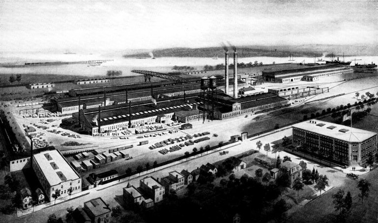
Works of The Babcock & Wilcox Co., at Bayonne, New Jersey
Works of The Babcock & Wilcox Co., in Bayonne, New Jersey
[Pg 5]
[Pg 5]
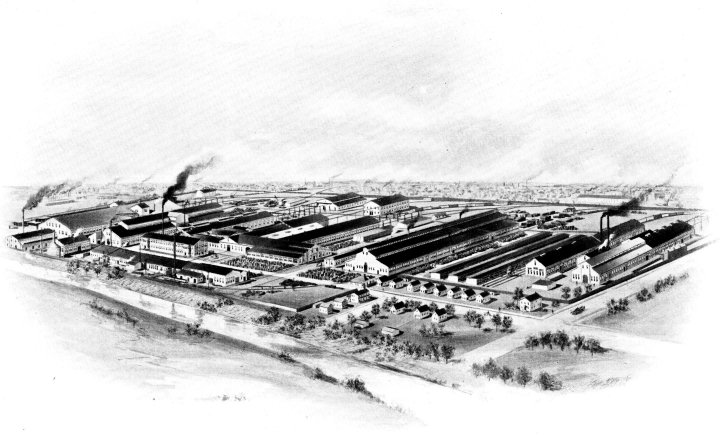
Works of The Babcock & Wilcox Co., at Barberton, Ohio
Works of The Babcock & Wilcox Co., at Barberton, Ohio
[Pg 8]
[Pg 8]

Works of Babcock & Wilcox, Limited, Renfrew, SCOTLAND
Works of Babcock & Wilcox, Limited, Renfrew, SCOTLAND
[Pg 9]
[Pg 9]
BABCOCK & WILCOX Limited
ORIEL HOUSE, FARRINGDON STREET, LONDON, E. C.
WORKS: RENFREW, SCOTLAND
Directors
| JOHN DEWRANCE, Chairman | CHARLES A. KNIGHT | ||
| ARTHUR T. SIMPSON | J. H. R. KEMNAL | ||
| WILLIAM D. HOXIE | Managing Director | ||
| E. H. WELLS | WALTER COLLS, | Secretary | |
Branch Offices in Great Britain
| GLASGOW: 29 St. Vincent Place | MANCHESTER: 30 Cross St. |
| BIRMINGHAM: Winchester Mystery House | MIDDLESBROUGH: The Exchange |
| CARDIFF: 129 Bute St. | NEWCASTLE: 42 Westgate Rd |
| BELFAST: Ocean Buildings, Donegal Square, East. | SHEFFIELD: 14 Bank Chambers, Fargate |
Offices Abroad
| BOMBAY: Wheeler’s Building, Hornby Road, Fort | MELBOURNE: 9 William St. |
| BRUSSELS: 187 Royal Street | MEXICO: 22-23 Tiburcio |
| BILBAO: 1 Albia Square | MILAN: 22 Prince Umberto Street |
| CALCUTTA: Clive Hall | MONTREAL: College Street, St. Henri |
| JOHANNESBURG: Merged Buildings | NAPLES: 107 Santa Lucia Street |
| LIMA: Peru | SHANGHAI: Jinkee Road |
| LISBON: 84-86 Commerce Street | SYDNEY: 427-429 Sussex St. |
| MADRID: Ventura de la Vega | TOKYO: Japan |
| TORONTO: Traders Bank Building | |
Representatives and Licensees in
| ADELAIDE, SA | CAIRO, Egypt | MOSCOW, Russia |
| ATHENS, Greece | CHILE, Valparaíso, South America | PERTH, WA |
| AUCKLAND, NZ | CHRISTIANIA, Norway | POLAND, Berlin |
| BAHIA, Brazil | COLOMBO, Sri Lanka | RANGOON, Myanmar |
| BANGKOK, Thailand | COPENHAGEN, Denmark | RIO DE JANEIRO, Brazil |
| BARCELONA, Spain | ESKILSTUNA, Sweden | SMYRNA, Anatolia |
| BRUNN, Austria | GIJON, Spain | SOURABAYA, Java |
| BUCHAREST, Romania | HELSINGFORS, Finland | ST. PETERSBURG, Russia |
| BUDAPEST, Hungary | HENGELO, Netherlands | TAMMERFORS, Finland |
| BUENOS AYRES, Argentina | KIMBERLEY, South Africa | THE HAGUE, Netherlands |
TELEGRAPHIC ADDRESS FOR ALL OFFICES EXCEPT BOMBAY AND CALCUTTA: “BABCOCK”
FOR BOMBAY AND CALCUTTA: “BOILER”
[Pg 10]
[Pg 10]

Fonderies et Ateliers de la Courneuve, Chaudières Babcock & Wilcox, Paris, France
Fonderies et Ateliers de la Courneuve, Chaudières Babcock & Wilcox, Paris, France
[Pg 11]
[Pg 11]
FONDERIES ET ATELIERS DE LA COURNEUVE
CHAUDIÈRES
BABCOCK & WILCOX
6 RUE LAFERRIÈRE, PARIS
WORKS: SEINE—LA COURNEUVE
Directors
| EDMOND DUPUIS | J. H. R. KEMNAL | |
| ETIENNE BESSON | IRÉNÉE CHAVANNE | |
| CHARLES A. KNIGHT | JULES LEMAIRE |
Branch Offices
| BORDEAUX: 30 Antoine Gautier Boulevard |
| LILLE: 23 Faidherbe Street |
| LYON: 28 Quai de la Guillotier |
| MARSEILLE: 21 Devilliers Course |
| MONTPELLIER: 1 Boussairolles Street |
| NANCY: 2 Rue de Lorraine |
| ST. ETIENNE: 13 Bourse Street |
REPRESENTATIVE FOR SWITZERLAND: SPOERRI & CIE, ZURICH
TELEGRAPHIC ADDRESS: “BABCOCK-PARIS”
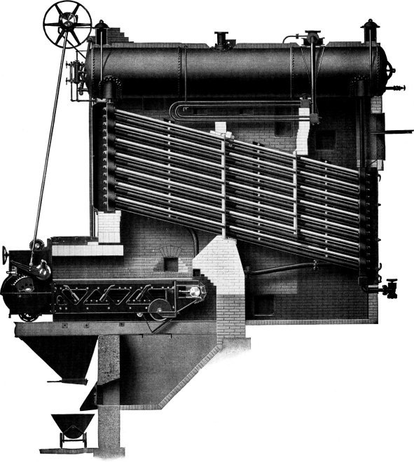
Wrought-steel Vertical Header Longitudinal Drum Babcock & Wilcox Boiler, Equipped with Babcock & Wilcox Superheater and Babcock & Wilcox Chain Grate Stoker
Wrought-steel Vertical Header Longitudinal Drum Babcock & Wilcox Boiler, Equipped with Babcock & Wilcox Superheater and Babcock & Wilcox Chain Grate Stoker
THE EARLY HISTORY OF THE GENERATION AND USE OF STEAM
While the time of man’s first knowledge and use of the expansive force of the vapor of water is unknown, records show that such knowledge existed earlier than 150 B. C. In a treatise of about that time entitled “Pneumatica”, Hero, of Alexander, described not only existing devices of his predecessors and contemporaries but also an invention of his own which utilized the expansive force of steam for raising water above its natural level. He clearly describes three methods in which steam might be used directly as a motive of power; raising water by its elasticity, elevating a weight by its expansive power and producing a rotary motion by its reaction on the atmosphere. The third method, which is known as “Hero’s engine”, is described as a hollow sphere supported over a caldron or boiler by two trunnions, one of which was hollow, and connected the interior of the sphere with the steam space of the caldron. Two pipes, open at the ends and bent at right angles, were inserted at opposite poles of the sphere, forming a connection between the caldron and the atmosphere. Heat being applied to the caldron, the steam generated passed through the hollow trunnion to the sphere and thence into the atmosphere through the two pipes. By the reaction incidental to its escape through these pipes, the sphere was caused to rotate and here is the primitive steam reaction turbine.
While the exact time when humans first discovered and used the expansive power of water vapor is unknown, records indicate that this knowledge existed before 150 B.C. In a treatise from around that period called “Pneumatica,” Hero of Alexandria described not only the devices of his predecessors and contemporaries but also one of his inventions that used steam power to raise water above its natural level. He outlines three methods for using steam directly as a source of power: raising water through its elasticity, lifting a weight with its expansive force, and creating rotary motion through its reaction with the atmosphere. The third method, known as “Hero’s engine,” is explained as a hollow sphere supported above a caldron or boiler by two trunnions, one of which was hollow and connected the inside of the sphere to the steam space of the caldron. Two pipes, open at the ends and bent at right angles, were inserted at opposite ends of the sphere, linking the caldron to the atmosphere. When heat was applied to the caldron, steam produced traveled through the hollow trunnion to the sphere and then into the atmosphere via the two pipes. The reaction that occurred when the steam escaped through these pipes caused the sphere to rotate, marking the invention of the primitive steam reaction turbine.
Hero makes no suggestions as to application of any of the devices he describes to a useful purpose. From the time of Hero until the late sixteenth and early seventeenth centuries, there is no record of progress, though evidence is found that such devices as were described by Hero were sometimes used for trivial purposes, the blowing of an organ or the turning of a skillet.
Hero doesn’t offer any ideas on how to use the devices he describes for practical purposes. From the time of Hero until the late sixteenth and early seventeenth centuries, there’s no record of progress, although there’s evidence that some of the devices described by Hero were occasionally used for minor tasks, like playing an organ or flipping a skillet.
Mathesius, the German author, in 1571; Besson, a philosopher and mathematician at Orleans; Ramelli, in 1588; Battista Delia Porta, a Neapolitan mathematician and philosopher, in 1601; Decause, the French engineer and architect, in 1615; and Branca, an Italian architect, in 1629, all published treatises bearing on the subject of the generation of steam.
Mathesius, the German author, in 1571; Besson, a philosopher and mathematician from Orleans; Ramelli, in 1588; Battista Della Porta, a Neapolitan mathematician and philosopher, in 1601; Decause, the French engineer and architect, in 1615; and Branca, an Italian architect, in 1629, all published works related to the topic of steam generation.
To the next contributor, Edward Somerset, second Marquis of Worcester, is apparently due the credit of proposing, if not of making, the first useful steam engine. In the “Century of Scantlings and Inventions”, published in London in 1663, he describes devices showing that he had in mind the raising of water not only by forcing it from two receivers by direct steam pressure but also for some sort of reciprocating piston actuating one end of a lever, the other operating a pump. His descriptions are rather obscure and no drawings are extant so that it is difficult to say whether there were any distinctly novel features to his devices aside from the double action. While there is no direct authentic record that any of the devices he described were actually constructed, it is claimed by many that he really built and operated a steam engine containing pistons.
To the next contributor, Edward Somerset, the second Marquis of Worcester, is apparently credited with proposing, if not actually creating, the first useful steam engine. In the “Century of Scantlings and Inventions,” published in London in 1663, he describes devices indicating that he envisioned raising water not only by pushing it from two receivers using direct steam pressure but also through some kind of reciprocating piston that moved one end of a lever while the other operated a pump. His descriptions are quite vague, and no drawings exist, making it hard to determine whether his devices had any distinctly new features besides the double action. While there’s no direct authentic record that any of the devices he described were ever actually built, many claim that he indeed constructed and operated a steam engine that included pistons.
In 1675, Sir Samuel Moreland was decorated by King Charles II, for a
demonstration of “a certain powerful machine to raise water.” Though
there appears to be no record of the design of this machine, the
mathematical dictionary, published in 1822, credits Moreland with the
first account of a steam engine, on which subject he wrote a treatise
that is still preserved in the British Museum.
[Pg 14]
In 1675, Sir Samuel Moreland was honored by King Charles II for showcasing “a powerful machine to raise water.” Although there doesn't seem to be any record of the machine's design, a mathematical dictionary published in 1822 credits Moreland with the first description of a steam engine, and he wrote a treatise on the subject that is still kept in the British Museum.
[Pg 14]

397 Horse-power Babcock & Wilcox Boiler in Course of Erection at the Plant of the Crocker Wheeler Co., Ampere, N. J.
397 Horse-power Babcock & Wilcox Boiler Being Installed at the Crocker Wheeler Co. Plant, Ampere, NJ.
[Pg 15] Dr. Denys Papin, an ingenious Frenchman, invented in 1680 “a steam digester for extracting marrowy, nourishing juices from bones by enclosing them in a boiler under heavy pressure,” and finding danger from explosion, added a contrivance which is the first safety valve on record.
[Pg 15] Dr. Denys Papin, a clever Frenchman, invented in 1680 “a steam digester for extracting rich, nutritious juices from bones by putting them in a boiler under high pressure,” and upon realizing the risk of explosion, added a mechanism that is the first recorded safety valve.
The steam engine first became commercially successful with Thomas Savery. In 1699, Savery exhibited before the Royal Society of England (Sir Isaac Newton was President at the time), a model engine which consisted of two copper receivers alternately connected by a three-way hand-operated valve, with a boiler and a source of water supply. When the water in one receiver had been driven out by the steam, cold water was poured over its outside surface, creating a vacuum through condensation and causing it to fill again while the water in the other reservoir was being forced out. A number of machines were built on this principle and placed in actual use as mine pumps.
The steam engine first became commercially successful thanks to Thomas Savery. In 1699, Savery showcased a model engine before the Royal Society of England (with Sir Isaac Newton as the President at the time). The engine had two copper receivers that were alternately connected by a three-way, hand-operated valve, along with a boiler and a water supply. When the steam pushed the water out of one receiver, cold water was poured over its outside surface, creating a vacuum through condensation and causing it to refill while the water in the other reservoir was being pushed out. Several machines were built using this principle and were actually used as pumps in mines.
The serious difficulty encountered in the use of Savery’s engine was the fact that the height to which it could lift water was limited by the pressure the boiler and vessels could bear. Before Savery’s engine was entirely displaced by its successor, Newcomen’s, it was considerably improved by Desaguliers, who applied the Papin safety valve to the boiler and substituted condensation by a jet within the vessel for Savery’s surface condensation.
The major problem with Savery's engine was that the height it could lift water was restricted by the pressure the boiler and components could withstand. Before Savery's engine was completely replaced by Newcomen's, it was significantly enhanced by Desaguliers, who introduced the Papin safety valve to the boiler and replaced Savery's surface condensation method with condensation using a jet inside the vessel.
In 1690, Papin suggested that the condensation of steam should be employed to make a vacuum beneath a cylinder which had previously been raised by the expansion of steam. This was the earliest cylinder and piston steam engine and his plan took practical shape in Newcomen’s atmospheric engine. Papin’s first engine was unworkable owing to the fact that he used the same vessel for both boiler and cylinder. A small quantity of water was placed in the bottom of the vessel and heat was applied. When steam formed and raised the piston, the heat was withdrawn and the piston did work on its down stroke under pressure of the atmosphere. After hearing of Savery’s engine, Papin developed an improved form. Papin’s engine of 1705 consisted of a displacement chamber in which a floating diaphragm or piston on top of the water kept the steam and water from direct contact. The water delivered by the downward movement of the piston under pressure, to a closed tank, flowed in a continuous stream against the vanes of a water wheel. When the steam in the displacement chamber had expanded, it was exhausted to the atmosphere through a valve instead of being condensed. The engine was, in fact, a non-condensing, single action steam pump with the steam and pump cylinders in one. A curious feature of this engine was a heater placed in the diaphragm. This was a mass of heated metal for the purpose of keeping the steam dry or preventing condensation during expansion. This device might be called the first superheater.
In 1690, Papin proposed using steam condensation to create a vacuum under a cylinder that had already been lifted by expanding steam. This was the first cylinder and piston steam engine, and his idea was practically realized in Newcomen’s atmospheric engine. Papin’s initial engine was impractical because he used the same vessel for both the boiler and the cylinder. A small amount of water was placed at the bottom of the vessel, and heat was applied. When steam formed and raised the piston, the heat was removed, allowing the piston to work on its downward stroke due to atmospheric pressure. After learning about Savery’s engine, Papin created an improved version. His 1705 engine had a displacement chamber with a floating diaphragm or piston on top of the water, preventing direct contact between steam and water. The water pushed down by the piston under pressure flowed continuously into a closed tank, driving a water wheel. When the steam in the displacement chamber expanded, it was released into the atmosphere through a valve instead of being condensed. The engine was essentially a non-condensing, single-action steam pump that combined the steam and pump cylinders. An interesting feature of this engine was a heater located in the diaphragm, made of heated metal to keep the steam dry and prevent condensation during expansion. This device could be considered the first superheater.
Among the various inventions attributed to Papin was a boiler with an internal fire box, the earliest record of such construction.
Among the various inventions credited to Papin was a boiler with an internal firebox, the earliest record of this kind of design.
While Papin had neglected his earlier suggestion of a steam and piston
engine to work on Savery’s ideas, Thomas Newcomen, with his assistant,
John Cawley, put into practical form Papin’s suggestion of 1690. Steam
admitted from the boiler to a cylinder raised a piston by its expansion,
assisted by a counter-weight on the other end of a beam actuated by the
piston. The steam valve was then shut and the steam condensed by a jet
of cold water. The piston was then forced downward by atmospheric
pressure and did work on the pump. The condensed water in the cylinder
was expelled through an escapement valve by the next entry of steam.
This engine used steam having pressure but little, if any, above that of
the atmosphere.
[Pg 16]
While Papin had overlooked his earlier idea of a steam and piston engine to explore Savery’s concepts, Thomas Newcomen, along with his assistant John Cawley, brought Papin’s 1690 suggestion to life. Steam released from the boiler into a cylinder pushed a piston upward through expansion, aided by a counterweight on the opposite end of a beam activated by the piston. The steam valve was then closed, and the steam was condensed using a jet of cold water. This caused atmospheric pressure to push the piston down, doing work on the pump. The condensed water in the cylinder was expelled through an escape valve with the next incoming steam. This engine operated using steam with pressure that was only slightly above atmospheric levels.
[Pg 16]

Two Units of 8128 Horse Power of Babcock & Wilcox Boilers and Superheaters at the Fisk Street Station of the Commonwealth Edison Co., Chicago, Ill., 50,400 Horse Power being Installed in this Station. The Commonwealth Edison Co. Operates in its Various Stations a Total of 86,000 Horse Power of Babcock & Wilcox Boilers, all Fitted with Babcock & Wilcox Superheaters and Equipped with Babcock & Wilcox Chain Grate Stokers
Two units of 8128 horsepower Babcock & Wilcox boilers and superheaters are being installed at the Fisk Street Station of the Commonwealth Edison Co. in Chicago, Illinois, adding up to a total of 50,400 horsepower at this station. The Commonwealth Edison Co. operates a total of 86,000 horsepower across its various stations, all featuring Babcock & Wilcox boilers, equipped with Babcock & Wilcox superheaters and chain grate stokers.
[Pg 17] In 1711, this engine was introduced into mines for pumping purposes. Whether its action was originally automatic or whether dependent upon the hand operation of the valves is a question of doubt. The story commonly believed is that a boy, Humphrey Potter, in 1713, whose duty it was to open and shut such valves of an engine he attended, by suitable cords and catches attached to the beam, caused the engine to automatically manipulate these valves. This device was simplified in 1718 by Henry Beighton, who suspended from the bottom, a rod called the plug-tree, which actuated the valve by tappets. By 1725, this engine was in common use in the collieries and was changed but little for a matter of sixty or seventy years. Compared with Savery’s engine, from the aspect of a pumping engine, Newcomen’s was a distinct advance, in that the pressure in the pumps was in no manner dependent upon the steam pressure. In common with Savery’s engine, the losses from the alternate heating and cooling of the steam cylinder were enormous. Though obviously this engine might have been modified to serve many purposes, its use seems to have been limited almost entirely to the pumping of water.
[Pg 17] In 1711, this engine was introduced in mines for pumping water. It's unclear if it was originally automatic or if it relied on manual operation of the valves. The popular story is that a boy named Humphrey Potter, in 1713, who was responsible for opening and closing the valves on the engine he worked with, used cords and catches attached to the beam to make the engine control these valves automatically. Henry Beighton simplified this device in 1718 by adding a rod called the plug-tree that activated the valve using tappets. By 1725, this engine was widely used in coal mines and underwent little change for about sixty or seventy years. Compared to Savery’s engine, Newcomen’s was a significant improvement as a pumping engine because the pressure in the pumps didn’t depend on steam pressure. Like Savery’s engine, however, it suffered from significant losses due to the alternating heating and cooling of the steam cylinder. Although the engine could have been adapted for various uses, it seems to have been mainly limited to pumping water.
The rivalry between Savery and Papin appears to have stimulated attention to the question of fuel saving. Dr. John Allen, in 1730, called attention to the fact that owing to the short length of time of the contact between the gases and the heating surfaces of the boiler, nearly half of the heat of the fire was lost. With a view to overcoming this loss at least partially, he used an internal furnace with a smoke flue winding through the water in the form of a worm in a still. In order that the length of passage of the gases might not act as a damper on the fire, Dr. Allen recommended the use of a pair of bellows for forcing the sluggish vapor through the flue. This is probably the first suggested use of forced draft. In forming an estimate of the quantity of fuel lost up the stack, Dr. Allen probably made the first boiler test.
The competition between Savery and Papin seems to have sparked interest in the issue of fuel efficiency. In 1730, Dr. John Allen pointed out that because the gases and the heating surfaces of the boiler had such a short interaction time, nearly half of the fire's heat was wasted. To address this loss at least in part, he implemented an internal furnace with a smoke flue that twisted through the water like a worm in a still. To ensure that the length of the gas passage wouldn’t smother the fire, Dr. Allen suggested using a pair of bellows to push the sluggish vapor through the flue. This is likely the first proposed use of forced draft. In estimating the amount of fuel lost up the stack, Dr. Allen probably conducted the first boiler test.
Toward the end of the period of use of Newcomen’s atmospheric engine, John Smeaton, who, about 1770, built and installed a number of large engines of this type, greatly improved the design in its mechanical details.
Toward the end of the time that Newcomen's atmospheric engine was in use, John Smeaton, who built and installed several large engines of this kind around 1770, made significant improvements to the design in its mechanical aspects.
The improvement in boiler and engine design of Smeaton, Newcomen and
their contemporaries, were followed by those of the great engineer,
James Watt, an instrument maker of Glasgow. In 1763, while repairing a
model of Newcomen’s engine, he was impressed by the great waste of steam
to which the alternating cooling and heating of the engine gave rise.
His remedy was the maintaining of the cylinder as hot as the entering
steam and with this in view he added a vessel separate from the
cylinder, into which the steam should pass from the cylinder and be
there condensed either by the application of cold water outside or by a
jet from within. To preserve a vacuum in his condenser, he added an air
pump which should serve to remove the water of condensation and air
brought in with the injection water or due to leakage. As the cylinder
no longer acted as a condenser, he could maintain it at a high
temperature by covering it with non-conducting material and, in
particular, by the use of a steam jacket. Further and with the same
object in view, he covered the top of the cylinder and introduced steam
above the piston to do the work previously accomplished by atmospheric
pressure. After several trials with an experimental apparatus based on
these ideas, Watt patented his improvements in 1769. Aside from their
historical importance, Watt’s improvements, as described in his
specification, are to this day a [Pg 18]
[Pg 19] statement of the principles which guide
the scientific development of the steam engine. His words are:
The advancements in boiler and engine design made by Smeaton, Newcomen, and their peers were succeeded by those of the renowned engineer, James Watt, an instrument maker from Glasgow. In 1763, while fixing a model of Newcomen’s engine, he noticed the significant waste of steam caused by the engine’s alternating cooling and heating. His solution was to keep the cylinder as hot as the incoming steam; to achieve this, he added a separate vessel for the steam to flow into from the cylinder, where it would be condensed either by applying cold water from the outside or by a jet from inside. To maintain a vacuum in his condenser, he included an air pump to remove condensation water and any air that came with the injection water or from leaks. Since the cylinder was no longer functioning as a condenser, he was able to keep its temperature high by insulating it and using a steam jacket. Additionally, to pursue the same goal, he covered the top of the cylinder and introduced steam above the piston to do the work that atmospheric pressure used to handle. After conducting several experiments based on these concepts, Watt patented his enhancements in 1769. Beyond their historical significance, Watt’s improvements, as outlined in his specification, still represent a [Pg 18]
[Pg 19] statement of the principles guiding the scientific advancement of the steam engine. His words are:

Erie County Electric Co., Erie, Pa., Operating 3082 Horse Power of Babcock & Wilcox Boilers and Superheaters, Equipped with Babcock & Wilcox Chain Grate Stokers
Erie County Electric Co., Erie, Pa., Operating 3082 Horse Power of Babcock & Wilcox Boilers and Superheaters, Equipped with Babcock & Wilcox Chain Grate Stokers
“My method of lessening the consumption of steam, and consequently fuel, in fire engines, consists of the following principles:
“My strategy for reducing steam use, and thus fuel consumption, in fire engines is based on the following principles:
“First, That vessel in which the powers of steam are to be employed to work the engine, which is called the cylinder in common fire engines, and which I call the steam vessel, must, during the whole time the engine is at work, be kept as hot as the steam that enters it; first, by enclosing it in a case of wood, or any other materials that transmit heat slowly; secondly, by surrounding it with steam or other heated bodies; and, thirdly, by suffering neither water nor any other substance colder than the steam to enter or touch it during that time.
“First, the part where the steam powers the engine, usually called the cylinder in standard fire engines, which I refer to as the steam vessel, needs to be kept as hot as the steam entering it for the entire time the engine is running. This should be accomplished by enclosing it in a case made of wood or other materials that transfer heat slowly; by surrounding it with steam or other heated substances; and by ensuring that water or any substance cooler than the steam doesn’t enter or touch it during that time."
“Secondly, In engines that are to be worked wholly or partially by condensation of steam, the steam is to be condensed in vessels distinct from the steam vessels or cylinders, although occasionally communicating with them; these vessels I call condensers; and, whilst the engines are working, these condensers ought at least to be kept as cold as the air in the neighborhood of the engines, by application of water or other cold bodies.
“Second, in engines that operate entirely or partially by condensing steam, the steam should be condensed in separate vessels from the steam vessels or cylinders, though they might connect occasionally; I call these vessels condensers. While the engines are running, these condensers should be kept at least as cold as the air around the engines, using water or other cold materials.”
“Thirdly, Whatever air or other elastic vapor is not condensed by the cold of the condenser, and may impede the working of the engine, is to be drawn out of the steam vessels or condensers by means of pumps, wrought by the engines themselves, or otherwise.
“Third, any air or other gases that aren't condensed by the cold of the condenser and could affect the engine’s performance need to be removed from the steam vessels or condensers using pumps powered by the engines themselves or by other methods.”
“Fourthly, I intend in many cases to employ the expansive force of steam to press on the pistons, or whatever may be used instead of them, in the same manner in which the pressure of the atmosphere is now employed in common fire engines. In cases where cold water cannot be had in plenty, the engines may be wrought by this force of steam only, by discharging the steam into the air after it has done its office….
“Fourth, I plan to use steam power to push on the pistons, or whatever replaces them, just like how atmospheric pressure is used in regular fire engines. In cases where there's not enough cold water, the engines can function solely on steam power by releasing the steam into the air after it's done its job….”
“Sixthly, I intend in some cases to apply a degree of cold not capable of reducing the steam to water, but of contracting it considerably, so that the engines shall be worked by the alternate expansion and contraction of the steam.
“Sixth, I plan to apply a level of cold in some cases that won’t turn the steam back into water but will significantly shrink it, allowing the engines to operate using the alternating expansion and contraction of the steam.”
“Lastly, Instead of using water to render the pistons and other parts of the engine air and steam tight, I employ oils, wax, resinous bodies, fat of animals, quick-silver and other metals in their fluid state.”
“Lastly, instead of using water to make the pistons and other parts of the engine airtight and steam-tight, I use oils, wax, resinous substances, animal fats, mercury, and other metals in their liquid form.”
The fifth claim was for a rotary engine, and need not be quoted here.
The fifth claim was for a rotary engine, and it doesn't need to be quoted here.
The early efforts of Watt are typical of those of the poor inventor struggling with insufficient resources to gain recognition and it was not until he became associated with the wealthy manufacturer, Mattheu Boulton of Birmingham, that he met with the success upon which his present fame is based. In partnership with Boulton, the business of the manufacture and the sale of his engines were highly successful in spite of vigorous attacks on the validity of his patents.
The early efforts of Watt are typical of those of an inventor struggling with limited resources to gain recognition, and it wasn't until he partnered with the wealthy manufacturer, Matthew Boulton of Birmingham, that he achieved the success upon which his current fame is based. Together with Boulton, the business of manufacturing and selling his engines was highly successful despite strong criticism of the validity of his patents.
Though the fourth claim of Watt’s patent describes a non-condensing
engine which would require high pressures, his aversion to such practice
was strong. Notwithstanding his entire knowledge of the advantages
through added expansion under high pressure, he continued to use
pressures not above 7 pounds per square inch above the atmosphere. To
overcome such pressures, his boilers were fed through a stand-pipe of
sufficient height to have the column of water offset the pressure within
the boiler. Watt’s attitude toward high pressure made his influence felt
long after his patents had expired.
[Pg 20]
Though the fourth claim of Watt’s patent describes a non-condensing engine that would need high pressures, he was strongly against using it. Despite knowing the benefits of increased expansion under high pressure, he kept using pressures no higher than 7 pounds per square inch above atmospheric pressure. To manage those pressures, his boilers were supplied through a stand-pipe tall enough to balance the pressure inside the boiler with the water column. Watt’s stance on high pressure continued to affect his influence long after his patents ran out.
[Pg 20]

Portion of 9600 Horse-power Installation of Babcock & Wilcox Boilers and Superheaters, Equipped with Babcock & Wilcox Chain Grate Stokers at the Blue Island, Ill., Plant of the Public Service Co. of Northern Illinois. This Company Operates 14,580 Horse Power of Babcock & Wilcox Boilers and Superheaters in its Various Stations
Portion of 9600 Horsepower Installation of Babcock & Wilcox Boilers and Superheaters, Equipped with Babcock & Wilcox Chain Grate Stokers at the Blue Island, Ill., Plant of the Public Service Company of Northern Illinois. This Company Operates 14,580 Horsepower of Babcock & Wilcox Boilers and Superheaters in its Various Stations.
[Pg 21] In 1782, Watt patented two other features which he had invented as early as 1769. These were the double acting engine, that is, the use of steam on both sides of the piston and the use of steam expansively, that is, the shutting off of steam from the cylinder when the piston had made but a portion of its stroke, the power for the completion of the stroke being supplied by the expansive force of the steam already admitted.
[Pg 21] In 1782, Watt patented two additional features that he had developed as early as 1769. These were the double-acting engine, meaning the use of steam on both sides of the piston, and the expansive use of steam, which involved shutting off steam from the cylinder when the piston had completed only part of its stroke, with the remaining power needed for the stroke coming from the expansive force of the steam that had already been let in.
He further added a throttle valve for the regulation of steam admission, invented the automatic governor and the steam indicator, a mercury steam gauge and a glass water column.
He also added a throttle valve to control steam intake, invented the automatic governor and the steam indicator, a mercury steam gauge, and a glass water column.
It has been the object of this brief history of the early developments in the use of steam to cover such developments only through the time of James Watt. The progress of the steam engine from this time through the stages of higher pressures, combining of cylinders, the application of steam vehicles and steamboats, the adding of third and fourth cylinders, to the invention of the turbine with its development and the accompanying development of the reciprocating engine to hold its place, is one long attribute to the inventive genius of man.
This brief history of early advancements in steam technology focuses on developments only up to the era of James Watt. The evolution of the steam engine from that point onward—through increased pressure, the combination of cylinders, the introduction of steam vehicles and boats, the addition of third and fourth cylinders, and the invention of the turbine, along with the advancement of the reciprocating engine to maintain its relevance—reflects the remarkable inventive genius of humanity.
While little is said in the biographies of Watt as to the improvement of steam boilers, all the evidence indicates that Boulton and Watt introduced the first “wagon boiler”, so called because of its shape. In 1785, Watt took out a number of patents for variations in furnace construction, many of which contain the basic principles of some of the modern smoke preventing furnaces. Until the early part of the nineteenth century, the low steam pressures used caused but little attention to be given to the form of the boiler operated in connection with the engines above described. About 1800, Richard Trevithick, in England, and Oliver Evans, in America, introduced non-condensing, and for that time, high pressure steam engines. To the initiative of Evans may be attributed the general use of high pressure steam in the United States, a feature which for many years distinguished American from European practice. The demand for light weight and economy of space following the beginning of steam navigation and the invention of the locomotive required boilers designed and constructed to withstand heavier pressures and forced the adoption of the cylindrical form of boiler. There are in use to-day many examples of every step in the development of steam boilers from the first plain cylindrical boiler to the most modern type of multi-tubular locomotive boiler, which stands as the highest type of fire-tube boiler construction.
While not much is mentioned in the biographies of Watt regarding improvements in steam boilers, all the evidence suggests that Boulton and Watt introduced the first “wagon boiler,” named for its shape. In 1785, Watt obtained several patents for different furnace designs, many of which include the basic principles of some modern smokeless furnaces. Until the early nineteenth century, the low steam pressures used meant that little attention was paid to the design of the boiler connected with the engines mentioned earlier. Around 1800, Richard Trevithick in England and Oliver Evans in America introduced non-condensing, and for that time, high-pressure steam engines. Evans is credited with the widespread use of high-pressure steam in the United States, which for many years set American practices apart from European ones. The demand for lighter and more space-efficient designs following the onset of steam navigation and the invention of the locomotive led to boilers being designed and built to handle higher pressures, prompting the adoption of the cylindrical boiler shape. Nowadays, there are many examples of every stage in the evolution of steam boilers, from the first simple cylindrical boilers to the most advanced multi-tubular locomotive boilers, which represent the pinnacle of fire-tube boiler design.
The early attempts to utilize water-tube boilers were few. A brief
history of the development of the boilers, in which this principle was
employed, is given in the following chapter. From this history it will
be clearly indicated that the first commercially successful utilization
of water tubes in a steam generator is properly attributed to George H.
Babcock and Stephen Wilcox.
[Pg 22]
The early efforts to use water-tube boilers were limited. A short history of the development of these boilers, where this principle was applied, is provided in the next chapter. From this history, it will be clearly shown that the first commercially successful use of water tubes in a steam generator is rightly credited to George H. Babcock and Stephen Wilcox.
[Pg 22]

BRIEF HISTORY OF WATER-TUBE BOILERS[1]

Blakey, 1766
As stated in the previous chapter, the first water-tube boiler was built by John Blakey and was patented by him in 1766. Several tubes alternately inclined at opposite angles were arranged in the furnaces, the adjacent tube ends being connected by small pipes. The first successful user of water-tube boilers, however, was James Rumsey, an American inventor, celebrated for his early experiments in steam navigation, and it is he who may be truly classed as the originator of the water-tube boiler. In 1788 he patented, in England, several forms of boilers, some of which were of the water-tube type. One had a fire box with flat top and sides, with horizontal tubes across the fire box connecting the water spaces. Another had a cylindrical fire box surrounded by an annular water space and a coiled tube was placed within the box connecting at its two ends with the water space. This was the first of the “coil boilers”. Another form in the same patent was the vertical tubular boiler, practically as made at the present time.
As mentioned in the previous chapter, the first water-tube boiler was created by John Blakey and patented by him in 1766. Several tubes were arranged in the furnaces, alternately inclined at opposite angles, with small pipes connecting the ends of adjacent tubes. The first person to successfully use water-tube boilers was James Rumsey, an American inventor known for his early work in steam navigation, and he is rightfully considered the originator of the water-tube boiler. In 1788, he patented several types of boilers in England, some of which were water-tube designs. One featured a firebox with a flat top and sides, with horizontal tubes across the firebox connecting the water spaces. Another had a cylindrical firebox surrounded by an annular water space, with a coiled tube inside the box connecting both ends to the water space. This was the first of the “coil boilers.” Another design in the same patent was the vertical tubular boiler, virtually identical to those made today.

John Stevens, 1804
The first boiler made of a combination of small tubes, connected at one end to a reservoir, was the invention of another American, John Stevens, in 1804. This boiler was actually employed to generate steam for running a steamboat on the Hudson River, but like all the “porcupine” boilers, of which type it was the first, it did not have the elements of a continued success.
The first boiler made of a bunch of small tubes, connected at one end to a tank, was invented by another American, John Stevens, in 1804. This boiler was actually used to generate steam for operating a steamboat on the Hudson River, but like all the "porcupine" boilers, which it was the first of, it didn't have the key elements for lasting success.

John Cox Stevens, 1805
Another form of water tube was patented in 1805 by John Cox Stevens, a son of John Stevens. This boiler consisted of twenty vertical tubes, 1¼ inches internal diameter and 40½ inches long, arranged in a circle, the outside diameter of which was approximately 12 inches, connecting a water chamber at the bottom with a steam chamber at the top. The steam and water chambers were annular spaces of small cross section and contained approximately 33 cubic inches. The illustration shows the cap of the steam chamber secured by bolts. The steam outlet pipe “A” is a pipe of one inch diameter, the water entering through a similar aperture at the bottom. One of these boilers was for a long time at the Stevens Institute of Technology at Hoboken, and is now in the Smithsonian Institute at Washington.
Another type of water tube was patented in 1805 by John Cox Stevens, the son of John Stevens. This boiler had twenty vertical tubes, 1¼ inches in internal diameter and 40½ inches long, arranged in a circle, with an outside diameter of about 12 inches, linking a water chamber at the bottom to a steam chamber at the top. The steam and water chambers were narrow annular spaces that held around 33 cubic inches. The illustration shows the cap of the steam chamber held in place by bolts. The steam outlet pipe “A” is a one-inch diameter pipe, with water entering through a similar opening at the bottom. One of these boilers was housed for a long time at the Stevens Institute of Technology in Hoboken and is now part of the collection at the Smithsonian Institute in Washington.
About the same time, Jacob Woolf built a boiler of large horizontal tubes, extending across the furnace and connected at the ends to a longitudinal drum above. The first purely sectional [Pg 24] water-tube boiler was built by Julius Griffith, in 1821. In this boiler, a number of horizontal water tubes were connected to vertical side pipes, the side pipes were connected to horizontal gathering pipes, and these latter in turn to a steam drum.
About the same time, Jacob Woolf constructed a boiler with large horizontal tubes that ran across the furnace and connected at the ends to a long drum above. The first completely sectional [Pg 24] water-tube boiler was created by Julius Griffith in 1821. In this boiler, several horizontal water tubes were attached to vertical side pipes, which were then linked to horizontal gathering pipes, and those were connected to a steam drum.

Joseph Eve, 1825
In 1822, Jacob Perkins constructed a flash boiler for carrying what was then considered a high pressure. A number of cast-iron bars having 1½ inches annular holes through them and connected at their outer ends by a series of bent pipes, outside of the furnace walls, were arranged in three tiers over the fire. The water was fed slowly to the upper tier by a force pump and steam in the superheated state was discharged to the lower tiers into a chamber from which it was taken to the engine.
In 1822, Jacob Perkins built a flash boiler to handle what was then seen as high pressure. Several cast-iron bars with 1½ inch circular holes were connected at their outer ends by a set of bent pipes outside the furnace walls, arranged in three tiers above the fire. Water was slowly supplied to the upper tier by a force pump, and superheated steam was released to the lower tiers into a chamber which directed it to the engine.
The first sectional water-tube boiler, with a well-defined circulation, was built by Joseph Eve, in 1825. The sections were composed of small tubes with a slight double curve, but being practically vertical, fixed in horizontal headers, which headers were in turn connected to a steam space above and a water space below formed of larger pipes. The steam and water spaces were connected by outside pipes to secure a circulation of the water up through the sections and down through the external pipes. In the same year, John M’Curdy of New York, built a “Duplex Steam Generator” of “tubes of wrought or cast iron or other material” arranged in several horizontal rows, connected together alternately at the front and rear by return bends. In the tubes below the water line were placed interior circular vessels closed at the ends in order to expose a thin sheet of water to the action of the fire.
The first sectional water-tube boiler, with a clear circulation system, was created by Joseph Eve in 1825. The sections were made up of small tubes with a slight double curve, oriented nearly vertically and fixed in horizontal headers, which were connected to a steam space above and a water space below, constructed from larger pipes. The steam and water spaces were linked by outside pipes to ensure water circulated up through the sections and down through the external pipes. In the same year, John M’Curdy from New York built a "Duplex Steam Generator" using "tubes made of wrought or cast iron or other materials," arranged in several horizontal rows and connected alternately at the front and back by return bends. Inside the tubes below the water line, there were interior circular vessels sealed at the ends to expose a thin layer of water to the heat from the fire.

Gurney, 1826
In 1826, Goldsworthy Gurney built a number of boilers, which he used on his steam carriages. A number of small tubes were bent into the shape of a “U” laid [Pg 25] sidewise and the ends were connected with larger horizontal pipes. These were connected by vertical pipes to permit of circulation and also to a vertical cylinder which served as a steam and water reservoir. In 1828, Paul Steenstrup made the first shell boiler with vertical water tubes in the large flues, similar to the boiler known as the “Martin” and suggesting the “Galloway”.
In 1826, Goldsworthy Gurney built several boilers to use in his steam carriages. He bent a number of small tubes into a “U” shape, laid [Pg 25] sideways, and connected the ends with larger horizontal pipes. These were linked by vertical pipes to allow for circulation and were also connected to a vertical cylinder that acted as a steam and water reservoir. In 1828, Paul Steenstrup created the first shell boiler with vertical water tubes in the large flues, which were similar to the boiler known as the “Martin” and reminiscent of the “Galloway.”
The first water-tube boiler having fire tubes within water tubes was built in 1830, by Summers & Ogle. Horizontal connections at the top and bottom were connected by a series of vertical water tubes, through which were fire tubes extending through the horizontal connections, the fire tubes being held in place by nuts, which also served to make the joint.
The first water-tube boiler with fire tubes inside water tubes was built in 1830 by Summers & Ogle. Horizontal connections at the top and bottom were linked by a series of vertical water tubes, with fire tubes running through the horizontal connections. The fire tubes were secured in place by nuts that also served to create the joint.

Stephen Wilcox, 1856
Stephen Wilcox, in 1856, was the first to use inclined water tubes connecting water spaces at the front and rear with a steam space above. The first to make such inclined tubes into a sectional form was Twibill, in 1865. He used wrought-iron tubes connected at the front and rear with standpipes through intermediate connections. These standpipes carried the system to a horizontal cross drum at the top, the entrained water being carried to the rear.
Stephen Wilcox, in 1856, was the first to use angled water tubes that connected water spaces at the front and back with a steam space above. The first person to create inclined tubes in a sectional design was Twibill, in 1865. He used wrought-iron tubes linked at the front and back with standpipes through additional connections. These standpipes transported the system to a horizontal cross drum at the top, with the water being carried to the rear.
Clarke, Moore, McDowell, Alban and others worked on the problem of constructing water-tube boilers, but because of difficulties of construction involved, met with no practical success.
Clarke, Moore, McDowell, Alban, and others tackled the challenge of building water-tube boilers, but due to the construction difficulties they faced, they achieved no practical success.

Twibill, 1865
It may be asked why water-tube boilers did not come into more general use at an early date, that is, why the number of water-tube boilers built was so small in comparison to the number of shell boilers. The reason for this is found in the difficulties involved in the design and construction of water-tube boilers, which design and construction required a high class of engineering and workmanship, while the plain cylindrical boiler is comparatively easy to build. The greater skill required to make a water-tube boiler successful is readily shown in the great number of failures in the attempts to make them.
It might be wondered why water-tube boilers didn't become more widely used earlier, meaning why so few water-tube boilers were produced compared to shell boilers. The answer lies in the challenges associated with designing and constructing water-tube boilers, which demanded a high level of engineering and craftsmanship, whereas the simple cylindrical boiler is much easier to construct. The higher skill needed to successfully create a water-tube boiler is clearly illustrated by the numerous failures that occurred in attempts to build them.
[Pg 26]
[Pg 26]

Partial View of 7000 Horse-power Installation of Babcock & Wilcox Boilers at the Philadelphia, Pa., Plant of the Baldwin Locomotive Works. This Company Operates in its Various Plants a Total of 9280 Horse Power of Babcock & Wilcox Boilers
Partial View of 7000 Horsepower Installation of Babcock & Wilcox Boilers at the Philadelphia, PA, plant of the Baldwin Locomotive Works. This company operates a total of 9280 horsepower of Babcock & Wilcox boilers across its various plants.
FOOTNOTES
[1] See discussion by George H. Babcock, of Stirling’s paper on “Water-tube and Shell Boilers”, in Transactions, American Society of Mechanical Engineers, Volume VI., Page 601.
[1] See George H. Babcock's comments on Stirling’s paper about “Water-tube and Shell Boilers” in the Transactions of the American Society of Mechanical Engineers, Volume VI, Page 601.
REQUIREMENTS OF STEAM BOILERS
Since the first appearance in “Steam” of the following “Requirements of a Perfect Steam Boiler”, the list has been copied many times either word for word or clothed in different language and applied to some specific type of boiler design or construction. In most cases, although full compliance with one or more of the requirements was structurally impossible, the reader was left to infer that the boiler under consideration possessed all the desirable features. It is noteworthy that this list of requirements, as prepared by George H. Babcock and Stephen Wilcox, in 1875, represents the best practice of to-day. Moreover, coupled with the boiler itself, which is used in the largest and most important steam generating plants throughout the world, the list forms a fitting monument to the foresight and genius of the inventors.
Since the first appearance in “Steam” of the following “Requirements of a Perfect Steam Boiler,” the list has been reproduced many times, either verbatim or phrased differently, and applied to specific types of boiler design or construction. In most cases, even though full compliance with one or more of the requirements was structurally impossible, readers were led to assume that the boiler being discussed had all the desired features. It’s noteworthy that this list of requirements, created by George H. Babcock and Stephen Wilcox in 1875, represents the best practices of today. Moreover, along with the boiler itself, which is used in the largest and most significant steam generating plants around the world, the list serves as a fitting tribute to the foresight and brilliance of the inventors.
REQUIREMENTS OF A PERFECT STEAM BOILER
1st. Proper workmanship and simple construction, using materials which experience has shown to be the best, thus avoiding the necessity of early repairs.
1st. Good workmanship and straightforward construction, using materials proven to be the best through experience, thus avoiding the need for early repairs.
2nd. A mud drum to receive all impurities deposited from the water, and so placed as to be removed from the action of the fire.
2nd. A mud drum to collect all impurities that settle from the water, positioned so it is away from the heat.
3rd. A steam and water capacity sufficient to prevent any fluctuation in steam pressure or water level.
3rd. A steam and water system that has enough capacity to prevent any changes in steam pressure or water level.
4th. A water surface for the disengagement of the steam from the water, of sufficient extent to prevent foaming.
4th. A water surface for the steam to separate from the water, large enough to avoid foaming.
5th. A constant and thorough circulation of water throughout the boiler, so as to maintain all parts at the same temperature.
5th. A steady and complete flow of water throughout the boiler, to keep all parts at the same temperature.
6th. The water space divided into sections so arranged that, should any section fail, no general explosion can occur and the destructive effects will be confined to the escape of the contents. Large and free passages between the different sections to equalize the water line and pressure in all.
6th. The water space is divided into sections arranged so that if any section fails, no major explosion can happen and the damaging effects will be limited to the release of the contents. There are large, open passages between the different sections to balance the water level and pressure throughout.
7th. A great excess of strength over any legitimate strain, the boiler being so constructed as to be free from strains due to unequal expansion, and, if possible, to avoid joints exposed to the direct action of the fire.
7th. An abundance of strength beyond any normal pressure, with the boiler designed to be free from stresses caused by uneven expansion and, whenever possible, to eliminate joints that are directly exposed to the fire.
8th. A combustion chamber so arranged that the combustion of the gases started in the furnace may be completed before the gases escape to the chimney.
8th. A combustion chamber designed in such a way that the burning of the gases initiated in the furnace can be finished before the gases exit to the chimney.
9th. The heating surface as nearly as possible at right angles to the currents of heated gases, so as to break up the currents and extract the entire available heat from the gases.
9th. The heating surface should be as close to right angles as possible to the flows of heated gases, in order to disrupt the flows and capture all available heat from the gases.
10th. All parts readily accessible for cleaning and repairs. This is a point of the greatest importance as regards safety and economy.
10th. All parts easily accessible for cleaning and repairs. This is a crucial point concerning safety and cost-effectiveness.
11th. Proportioned for the work to be done, and capable of working to its full rated capacity with the highest economy.
11th. Designed for the tasks at hand and able to operate at its full capacity with maximum efficiency.
12th. Equipped with the very best gauges, safety valves and other fixtures.
12th. Equipped with top-of-the-line gauges, safety valves, and other fixtures.
The exhaustive study made of each one of these requirements is shown by the following extract from a lecture delivered by Mr. Geo. H. Babcock at Cornell University in 1890 upon the subject:
The thorough study of each of these requirements is illustrated by the following excerpt from a lecture given by Mr. Geo. H. Babcock at Cornell University in 1890 on the topic:
THE CIRCULATION OF WATER IN STEAM BOILERS
You have all noticed a kettle of water boiling over the fire, the fluid rising somewhat tumultuously around the edges of the vessel, and tumbling toward the center, where it descends. Similar currents are in action while the water is simply being heated, but they are not perceptible unless there are floating particles in the liquid. These currents are caused by the joint action of the added temperature and two or more qualities which the water possesses.
You’ve all seen a kettle of water boiling on the stove, the liquid bubbling wildly at the edges of the pot and swirling towards the center, where it goes down. Similar movements happen while the water is just being heated, but they’re not noticeable unless there are floating particles in the liquid. These currents are caused by the combined effect of the added heat and two or more properties that the water has.
1st. Water, in common with most other substances, expands when heated; a statement, however, strictly true only when referred to a temperature above 39 degrees F. or 4 degrees C., but as in the making of steam we rarely have to do with temperatures so low as that, we may, for our present purposes, ignore that exception.
1st. Water, like most other substances, expands when heated; this is strictly true only at temperatures above 39 degrees F or 4 degrees C. However, since we rarely deal with such low temperatures when making steam, we can ignore that exception for now.
2nd. Water is practically a non-conductor of heat, though not entirely so. If ice-cold water was kept boiling at the surface the heat would not penetrate sufficiently to begin melting ice at a depth of 3 inches in less than about two hours. As, therefore, the heated water cannot impart its heat to its neighboring particles, it remains expanded and rises by its levity, while colder portions come to be heated in turn, thus setting up currents in the fluid.
2nd. Water is mostly a poor conductor of heat, but not completely. If ice-cold water was kept boiling at the surface, the heat wouldn’t reach deep enough to start melting ice at a depth of 3 inches in less than about two hours. Since the hot water can’t pass its heat to the nearby particles, it stays expanded and rises because it’s lighter, while the colder parts get heated up in turn, creating currents in the liquid.

Fig. 1
Now, when all the water has been heated to the boiling point corresponding to the pressure to which it is subjected, each added unit of heat converts a portion, about 7 grains in weight, into vapor, greatly increasing its volume; and the mingled steam and water rises more rapidly still, producing ebullition such as we have noticed in the kettle. So long as the quantity of heat added to the contents of the kettle continues practically constant, the conditions remain similar to those we noticed at first, a tumultuous lifting of the water around the edges, flowing toward the center and thence downward; if, however, the fire be quickened, the upward currents interfere with the downward and the kettle boils over (Fig. 1).
Now, when all the water has been heated to its boiling point based on the pressure it's under, each additional unit of heat turns about 7 grains of it into steam, significantly increasing its volume. The mixture of steam and water rises even faster, creating the bubbling we observe in a kettle. As long as the heat added to the kettle's contents remains nearly constant, the conditions are similar to what we noticed at the start, with chaotic lifting of the water around the edges, flowing toward the center and then downward. However, if the fire is intensified, the rising currents clash with the sinking ones, causing the kettle to spill over (Fig. 1).

Fig. 2
If now we put in the kettle a vessel somewhat smaller (Fig. 2) with a hole in the bottom and supported at a proper distance from the side so as to separate the upward from the downward currents, we can force the fires to a very much greater extent without causing the kettle to boil over, and when we place a deflecting plate so as to guide the rising column toward the center it will be almost impossible to produce that effect. This is the invention of Perkins in 1831 and forms the basis of very many of the arrangements for producing free circulation of the water in boilers which have been made since that time. It consists in dividing the currents so that they will not interfere each with the other.
If we now place a smaller vessel (Fig. 2) with a hole in the bottom into the kettle, supported at a proper distance from the side to separate the upward and downward currents, we can significantly enhance the fires without causing the kettle to boil over. When we add a deflecting plate to guide the rising column toward the center, it becomes nearly impossible to achieve boiling over. This invention by Perkins in 1831 serves as the foundation for many designs aimed at promoting free circulation of water in boilers that have been created since then. It involves dividing the currents to prevent them from interfering with each other.
[Pg 29]
[Pg 29]

Fig. 3
But what is the object of facilitating the circulation of water in boilers? Why may we not safely leave this to the unassisted action of nature as we do in culinary operations? We may, if we do not care for the three most important aims in steam-boiler construction, namely, efficiency, durability, and safety, each of which is more or less dependent upon a proper circulation of the water. As for efficiency, we have seen one proof in our kettle. When we provided means to preserve the circulation, we found that we could carry a hotter fire and boil away the water much more rapidly than before. It is the same in a steam boiler. And we also noticed that when there was nothing but the unassisted circulation, the rising steam carried away so much water in the form of foam that the kettle boiled over, but when the currents were separated and an unimpeded circuit was established, this ceased, and a much larger supply of steam was delivered in a comparatively dry state. Thus, circulation increases the efficiency in two ways: it adds to the ability to take up the heat, and decreases the liability to waste that heat by what is technically known as priming. There is yet another way in which, incidentally, circulation increases efficiency of surface, and that is by preventing in a greater or less degree the formation of deposits thereon. Most waters contain some impurity which, when the water is evaporated, remains to incrust the surface of the vessel. This incrustation becomes very serious sometimes, so much so as to almost entirely prevent the transmission of heat from the metal to the water. It is said that an incrustation of only one-eighth inch will cause a loss of 25 per cent in efficiency, and this is probably within the truth in many cases. Circulation of water will not prevent incrustation altogether, but it lessens the amount in all waters, and almost entirely so in some, thus adding greatly to the efficiency of the surface.
But what’s the point of helping water circulate in boilers? Why can’t we just rely on nature’s natural flow like we do when cooking? We can, but only if we don't care about the three key goals in steam-boiler design: efficiency, durability, and safety—each of which depends on proper water circulation. For efficiency, our kettle provides a clear example. When we ensured there was good circulation, we could use a hotter fire and boil the water much faster than before. It’s the same with a steam boiler. We also noticed that when we only relied on natural circulation, the rising steam carried away so much water as foam that the kettle boiled over. But once we created a controlled circulation, that stopped, and we got a lot more steam in a drier state. So, circulation boosts efficiency in two ways: it improves heat absorption and reduces heat loss, known as priming. Additionally, circulation helps maintain the efficiency of the surface by minimizing the buildup of deposits. Most waters have impurities that, when the water evaporates, leave behind deposits on the vessel’s surface. This buildup can become quite serious, sometimes blocking heat transfer from the metal to the water almost completely. It’s said that a deposit just one-eighth of an inch thick can lead to a 25 percent loss in efficiency, which is likely true in many cases. While water circulation won't eliminate deposits entirely, it reduces their formation in all types of water, and almost entirely in some, significantly enhancing the efficiency of the surface.

Fig. 4
A second advantage to be obtained through circulation is durability of the boiler. This it secures mainly by keeping all parts at a nearly uniform temperature. The way to secure the greatest freedom from unequal strains in a boiler is to provide for such a circulation of the water as will insure the same temperature in all parts.
A second benefit of circulation is the durability
3rd. Safety follows in the wake of durability, because a boiler which is not subject to unequal strains of expansion and contraction is not only less liable to ordinary repairs, but also to rupture and disastrous explosion. By far the most prolific cause of explosions is this same strain from unequal expansions.
3rd. Safety comes after durability because a boiler that isn't subject to uneven expansion and contraction is not only less likely to need regular repairs but also less prone to breaking and catastrophic explosions. By far, the most common cause of explosions is this same strain from uneven expansions.
Having thus briefly looked at the advantages of circulation of water in
steam boilers, let us see what are the best means of securing it under
the most efficient conditions We have seen in our kettle that one
essential point was that the currents should be kept from interfering
with each other. If we could look into an ordinary return tubular boiler
when steaming, we should see a curious commotion of currents rushing
hither and thither, and shifting continually as one or the other
contending force gained a momentary mastery. The principal upward
currents would be found at the two ends, one over the fire and the other
over the first foot or so of the tubes. Between these, the downward
currents struggle [Pg 30]
[Pg 31] against the rising currents of steam and water. At a
sudden demand for steam, or on the lifting of the safety valve, the
pressure being slightly reduced, the water jumps up in jets at every
portion of the surface, being lifted by the sudden generation of steam
throughout the body of water. You have seen the effect of this sudden
generation of steam in the well-known experiment with a Florence flask,
to which a cold application is made while boiling water under pressure
is within. You have also witnessed the geyser-like action when water is
boiled in a test tube held vertically over a lamp (Fig. 3).
Having briefly examined the benefits of water circulation in steam boilers, let's explore the best ways to maintain it under optimal conditions. In our kettle, we noticed that a key point was keeping the currents from interfering with each other. If we could look inside a typical return tubular boiler while it was steaming, we would see a chaotic swirl of currents moving around, constantly shifting as one force temporarily gained control. The main upward currents would be at both ends, one above the fire and the other over the first foot or so of the tubes. In between, the downward currents compete against the rising currents of steam and water. When there’s a sudden demand for steam, or when the safety valve opens and the pressure drops slightly, the water surges up in jets across the surface, propelled by the rapid generation of steam throughout the body of water. You’ve probably seen this sudden generation of steam in the classic experiment with a Florence flask when you apply something cold while boiling water under pressure inside. You’ve also observed the geyser-like effect when water is boiled in a test tube held vertically over a lamp (Fig. 3).

386 Horse-power Installation of Babcock & Wilcox Boilers at B. F. Keith’s Theatre, Boston, Mass.
386 Horsepower Installation of Babcock & Wilcox Boilers at B. F. Keith's Theatre, Boston, MA.

Fig. 5
If now we take a U-tube depending from a vessel of water (Fig. 4) and apply the lamp to one leg a circulation is at once set up within it, and no such spasmodic action can be produced. Thus U-tube is the representative of the true method of circulation within a water-tube boiler properly constructed. We can, for the purpose of securing more heating surface, extend the heated leg into a long incline (Fig. 5), when we have the well-known inclined-tube generator. Now, by adding other tubes, we may further increase the heating surface (Fig. 6), while it will still be the U-tube in effect and action. In such a construction the circulation is a function of the difference in density of the two columns. Its velocity is measured by the well-known Torricellian formula, V = (2gh)½, or, approximately V = 8(h)½, h being measured in terms of the lighter fluid. This velocity will increase until the rising column becomes all steam, but the quantity or weight circulated will attain a maximum when the density of the mingled steam and water in the rising column becomes one-half that of the solid water in the descending column which is nearly coincident with the condition of half steam and half water, the weight of the steam being very slight compared to that of the water.
If we take a U-tube connected to a container of water (Fig. 4) and apply heat to one leg, circulation is instantly set up within it, and no spasmodic action occurs. This U-tube represents the proper method of circulation in a well-designed water-tube boiler. To create more heating surface, we can extend the heated leg into a long incline (Fig. 5), forming the well-known inclined-tube generator. By adding more tubes, we can further increase the heating surface (Fig. 6), while it will still function as a U-tube in terms of effect and action. In this design, circulation depends on the difference in density between the two columns. Its velocity is calculated using the familiar Torricellian formula, V = (2gh)½, or approximately V = 8(h)½, with h being measured with respect to the lighter fluid. This velocity will increase until the rising column consists entirely of steam, but the amount or weight circulated will reach a maximum when the density of the mixed steam and water in the rising column is half that of the solid water in the descending column, which is nearly at the balance of half steam and half water, as the weight of the steam is very slight compared to that of the water.
It becomes easy by this rule to determine the circulation in any given boiler built on this principle, provided the construction is such as to permit a free flow of the water. Of course, every bend detracts a little and something is lost in getting up the velocity, but when the boiler is well arranged and proportioned these retardations are slight.
It’s straightforward with this guideline to figure out the circulation in any boiler designed based on this principle, as long as the structure allows for a smooth flow of water. Naturally, every bend slows things down a bit, and there’s some loss when trying to increase the speed, but when the boiler is properly set up and balanced, these delays are minimal.

Fig. 6
Let us take for example one of the 240 horse-power Babcock & Wilcox
boilers here in the University. The height of the columns may be taken
as 4½ feet, measuring from the surface of the water to about the center
of the bundle of tubes over the fire, and the head would be equal to
this height at the maximum of circulation. We should, therefore, have a
velocity of 8(4½)½ = 16.97, say 17 feet per second. There are in this
boiler fourteen sections, each having a 4-inch tube opening into the
drum, the area of which (inside) is 11 square inches, the fourteen
aggregating 154 square inches, or 1.07 square feet. This multiplied by
the velocity, 16.97 feet, gives 18.16 cubic feet mingled steam and water
discharged per second, one-half of which, or 9.08 cubic feet, is steam.
Assuming this steam to be at 100 pounds gauge pressure, it will weigh
0.258 pound per cubic foot. Hence, 2.34 pounds of steam will be
[Pg 32]
[Pg 33] discharged per second, and 8,433 pounds per hour. Dividing this by 30,
the number of pounds representing a boiler horse power, we get 281.1
horse power, about 17 per cent, in excess of the rated power of the
boiler. The water at the temperature of steam at 100 pounds pressure
weighs 56 pounds per cubic foot, and the steam 0.258 pound, so that the
steam forms but 1⁄218 part of the mixture by weight, and consequently
each particle of water will make 218 circuits before being evaporated
when working at this capacity, and circulating the maximum weight of
water through the tubes.
Let’s consider one of the 240 horsepower Babcock & Wilcox boilers at the University. The height of the columns is about 4½ feet, measured from the water surface to the middle of the bundle of tubes above the fire, and this height represents the maximum head in circulation. Therefore, we would have a velocity of 8(4½)½ = 16.97, or roughly 17 feet per second. This boiler has fourteen sections, each with a 4-inch tube connected to the drum, and the inside area of each is 11 square inches. The total area for the fourteen tubes adds up to 154 square inches, or 1.07 square feet. When we multiply this area by the velocity of 16.97 feet, we find that 18.16 cubic feet of mixed steam and water is discharged every second, half of which—9.08 cubic feet—is steam. Assuming this steam is at a gauge pressure of 100 pounds, its weight is 0.258 pounds per cubic foot. Therefore, 2.34 pounds of steam will be [Pg 32]
[Pg 33] discharged every second, totaling 8,433 pounds per hour. If we divide this by 30, the weight representing one boiler horsepower, we calculate 281.1 horsepower, which is about 17 percent more than the boiler's rated power. Water at the temperature of steam at 100 pounds pressure weighs 56 pounds per cubic foot, while steam weighs 0.258 pounds, meaning steam is only 1⁄218 of the mixture by weight. Consequently, each particle of water will make 218 circuits before being evaporated when operating at this capacity and circulating the maximum weight of water through the tubes.

A Portion of 9600 Horse-power Installation of Babcock & Wilcox Boilers and Superheaters Being Erected at the South Boston, Mass., Station of the Boston Elevated Railway Co. This Company Operates in its Various Stations a Total of 46,400 Horse Power of Babcock & Wilcox Boilers
A portion of a 9600 horsepower installation of Babcock & Wilcox boilers and superheaters is being set up at the South Boston, MA station of the Boston Elevated Railway Co. This company operates a total of 46,400 horsepower of Babcock & Wilcox boilers across its various stations.

Fig. 7
It is evident that at the highest possible velocity of exit from the generating tubes, nothing but steam will be delivered and there will be no circulation of water except to supply the place of that evaporated. Let us see at what rate of steaming this would occur with the boiler under consideration. We shall have a column of steam, say 4 feet high on one side and an equal column of water on the other. Assuming, as before, the steam at 100 pounds and the water at same temperature, we will have a head of 866 feet of steam and an issuing velocity of 235.5 feet per second. This multiplied by 1.07 square feet of opening by 3,600 seconds in an hour, and by 0.258 gives 234,043 pounds of steam, which, though only one-eighth the weight of mingled steam and water delivered at the maximum, gives us 7,801 horse power, or 32 times the rated power of the boiler. Of course, this is far beyond any possibility of attainment, so that it may be set down as certain that this boiler cannot be forced to a point where there will not be an efficient circulation of the water. By the same method of calculation it may be shown that when forced to double its rated power, a point rarely expected to be reached in practice, about two-thirds the volume of mixture of steam and water delivered into the drum will be steam, and that the water will make 110 circuits while being evaporated. Also that when worked at only about one-quarter its rated capacity, one-fifth of the volume will be steam and the water will make the rounds 870 times before it becomes steam. You will thus see that in the proportions adopted in this boiler there is provision for perfect circulation under all the possible conditions of practice.
It’s clear that at the highest possible exit speed from the generating tubes, only steam will be produced, and there will be no water circulation except to replace what has evaporated. Let's determine at what steaming rate this would happen with the boiler in question. We will have a column of steam, say 4 feet high on one side and an equal column of water on the other. Assuming, as before, the steam is at 100 pounds and the water at the same temperature, we will have a height of 866 feet of steam and a flow velocity of 235.5 feet per second. Multiplying this by 1.07 square feet of opening, by 3,600 seconds in an hour, and by 0.258 gives us 234,043 pounds of steam, which, although it’s only one-eighth the weight of the mixture of steam and water delivered at the maximum, provides us with 7,801 horsepower, or 32 times the rated capacity of the boiler. Of course, this is far beyond any achievable level, so it can be safely concluded that this boiler cannot be pushed to a point where there won’t be efficient water circulation. By using the same calculation method, it can be shown that when pushed to double its rated power, a level rarely achieved in practice, about two-thirds of the mixture's volume of steam and water delivered into the drum will be steam, and the water will make 110 circuits while being evaporated. Also, when operating at only around one-quarter of its rated capacity, one-fifth of the volume will be steam, and the water will cycle 870 times before turning into steam. This demonstrates that the design of this boiler allows for perfect circulation under all practical conditions.

Fig. 8 [Developed to show Circulation]
In designing boilers of this style it is necessary to guard against
having the uptake at the upper end of the tubes too large, for if
sufficiently large to allow downward currents therein, the whole effect
of the rising column in increasing the circulation in the tubes is
nullified (Fig. 7). This will readily be seen if we consider the uptake
very large when the only head producing circulation in the tubes will be
that due to the inclination of each tube taken by itself. This objection
is only overcome when the uptake is so small as to be entirely filled
with the ascending current of mingled steam and water. It is also
necessary that this uptake should be practically direct, and it should
not be composed of frequent enlargements and [Pg 34]
[Pg 35] contractions. Take, for
instance, a boiler well known in Europe, copied and sold here under
another name. It is made up of inclined tubes secured by pairs into
boxes at the ends, which boxes are made to communicate with each other
by return bends opposite the ends of the tubes. These boxes and return
bends form an irregular uptake, whereby the steam is expected to rise to
a reservoir above. You will notice (Fig. 8) that the upward current of
steam and water in the return bend meets and directly antagonizes the
upward current in the adjoining tube. Only one result can follow. If
their velocities are equal, the momentum of both will be neutralized and
all circulation stopped, or, if one be stronger, it will cause a back
flow in the other by the amount of difference in force, with practically
the same result.
In designing boilers of this type, it's important to prevent the uptake at the upper end of the tubes from being too large. If it’s large enough to allow downward currents, it negates the effect of the rising column in boosting circulation in the tubes (Fig. 7). This becomes clear when we think about a very large uptake, where the only pump driving circulation in the tubes would be the incline of each tube on its own. This issue is only resolved when the uptake is small enough to be fully filled with the ascending mix of steam and water. Additionally, this uptake should be as direct as possible and should not consist of frequent enlargements and [Pg 34] [Pg 35] contractions. For example, consider a boiler that is well-known in Europe and is sold here under a different name. It consists of inclined tubes secured in pairs into boxes at the ends, which boxes are connected to each other by return bends located opposite the ends of the tubes. These boxes and return bends create an irregular uptake, expecting the steam to rise to a reservoir above. You’ll see (Fig. 8) that the upward flow of steam and water in the return bend clashes directly with the upward flow in the adjacent tube. Only one outcome can result from this. If their velocities are equal, the momentum of both will cancel out and all circulation will stop, or if one is stronger, it will create a backflow in the other based on the force difference, leading to practically the same issue.

4880 Horse-power Installation of Babcock & Wilcox Boilers at the Open Hearth Plant of the Cambria Steel Co., Johnstown, Pa. This Company Operates a Total of 52,000 Horse Power of Babcock & Wilcox Boilers
4880 Horse-power Installation of Babcock & Wilcox Boilers at the Open Hearth Plant of the Cambria Steel Co., Johnstown, Pa. This Company Operates a Total of 52,000 Horse Power of Babcock & Wilcox Boilers

Fig. 9
In a well-known boiler, many of which were sold, but of which none are now made and a very few are still in use, the inventor claimed that the return bends and small openings against the tubes were for the purpose of “restricting the circulation” and no doubt they performed well that office; but excepting for the smallness of the openings they were not as efficient for that purpose as the arrangement shown in Fig. 8.
In a well-known boiler, many of which were sold but none are made now and very few are still in use, the inventor claimed that the return bends and small openings near the tubes were meant to "restrict the circulation," and they probably did that job well; however, aside from the small size of the openings, they weren't as effective for that purpose as the setup shown in Fig. 8.
Another form of boiler, first invented by Clarke or Crawford, and lately revived, has the uptake made of boxes into which a number, generally from two to four tubes, are expanded, the boxes being connected together by nipples (Fig. 9). It is a well-known fact that where a fluid flows through a conduit which enlarges and then contracts, the velocity is lost to a greater or less extent at the enlargements, and has to be gotten up again at the contractions each time, with a corresponding loss of head. The same thing occurs in the construction shown in Fig. 9. The enlargements and contractions quite destroy the head and practically overcome the tendency of the water to circulate.
Another type of boiler, first created by Clarke or Crawford and recently brought back, has its uptake made of boxes that contain a number of tubes, usually between two and four. These boxes are connected by nipples (Fig. 9). It's well known that when a fluid flows through a pipe that expands and then narrows, it loses velocity at the wider sections and has to regain it at the narrower ones, resulting in a loss of pressure. The same issue happens in the design shown in Fig. 9. The expansions and contractions greatly diminish the pressure and significantly hinder the water’s ability to circulate.

Fig. 10
A horizontal tube stopped at one end, as shown in Fig. 10, can have no proper circulation within it. If moderately driven, the water may struggle in against the issuing steam sufficiently to keep the surface covered, but a slight degree of forcing will cause it to act like the test tube in Fig. 3, and the more there are of them in a given boiler the more spasmodic will be its working.
A horizontal tube closed at one end, as shown in Fig. 10, can't have proper circulation inside it. If it's pushed moderately, the water might manage to flow in against the steam coming out enough to keep the surface covered, but if there's a slight increase in pressure, it will behave like the test tube in Fig. 3, and the more of these tubes there are in a boiler, the more erratic its operation will be.
The experiment with our kettle (Fig. 2) gives the clue to the best means of promoting circulation in ordinary shell boilers. Steenstrup or “Martin” and “Galloway” water tubes placed in such boilers also assist in directing the circulation therein, but it is almost impossible to produce in shell boilers, by any means the circulation of all the water in one continuous round, such as marks the well-constructed water-tube boiler.
The experiment with our kettle (Fig. 2) provides insight into the best way to enhance circulation in standard shell boilers. Steenstrup or “Martin” and “Galloway” water tubes installed in these boilers also help direct the circulation; however, it's nearly impossible to achieve the kind of continuous circulation for all the water in shell boilers that is characteristic of a well-designed water-tube boiler.
As I have before remarked, provision for a proper circulation of water has been almost universally ignored in designing steam boilers, sometimes to the great damage of the owner, but oftener to the jeopardy of the lives of those who are employed to run them. The noted case of the Montana and her sister ship, where some $300,000 [Pg 36] was thrown away in trying an experiment which a proper consideration of this subject would have avoided, is a case in point; but who shall count the cost of life and treasure not, perhaps, directly traceable to, but, nevertheless, due entirely to such neglect in design and construction of the thousands of boilers in which this necessary element has been ignored?
As I've mentioned before, proper water circulation has been largely overlooked in the design of steam boilers, often leading to significant financial losses for the owner, but more commonly putting the lives of those operating them at risk. A well-known example is the incident involving the Montana and her sister ship, where around $300,000 [Pg 36] was wasted on an experiment that could have been avoided with proper attention to this issue. But who can truly measure the cost in terms of lives and money that, while not always directly linked, are still completely attributable to the neglect of this vital aspect in the design and construction of the thousands of boilers that ignore this essential element?
In the light of the performance of the exacting conditions of present day power-plant practice, a review of this lecture and of the foregoing list of requirements reveals the insight of the inventors of the Babcock & Wilcox boiler into the fundamental principles of steam generator design and construction.
In light of the demanding conditions of today's power plant practices, a review of this lecture and the list of requirements shows the inventors of the Babcock & Wilcox boiler had a deep understanding of the fundamental principles of steam generator design and construction.
Since the Babcock & Wilcox boiler became thoroughly established as a durable and efficient steam generator, many types of water-tube boilers have appeared on the market. Most of them, failing to meet enough of the requirements of a perfect boiler, have fallen by the wayside, while a few failing to meet all of the requirements, have only a limited field of usefulness. None have been superior, and in the most cases the most ardent admirers of other boilers have been satisfied in looking up to the Babcock & Wilcox boiler as a standard and in claiming that the newer boilers were “just as good.”
Since the Babcock & Wilcox boiler became well-established as a reliable and efficient steam generator, many types of water-tube boilers have surfaced in the market. Most of them, not meeting enough of the criteria for a perfect boiler, have fallen out of favor, while a few that do not meet all the requirements have only limited practical applications. None have outperformed the Babcock & Wilcox, and in most cases, even the most passionate supporters of other boilers have acknowledged the Babcock & Wilcox boiler as the benchmark, claiming that the newer boilers were “just as good.”
Records of recent performances under the most severe conditions of services on land and sea, show that the Babcock & Wilcox boiler can be run continually and regularly at higher overloads, with higher efficiency, and lower upkeep cost than any other boiler on the market. It is especially adapted for power-plant work where it is necessary to use a boiler in which steam can be raised quickly and the boiler placed on the line either from a cold state or from a banked fire in the shortest possible time, and with which the capacity, with clean feed water, will be largely limited by the amount of coal that can be burned in the furnace.
Records of recent performances under the toughest conditions on land and sea show that the Babcock & Wilcox boiler can operate continuously and reliably at higher overloads, with better efficiency and lower maintenance costs than any other boiler available. It's especially designed for power-plant operations where it's important to be able to raise steam quickly, allowing the boiler to be brought online either from a cold state or from a banked fire in the shortest time possible. With clean feed water, its capacity will primarily depend on how much coal can be burned in the furnace.
The distribution of the circulation through the separate headers and sections and the action of the headers in forcing a maximum and continuous circulation in the lower tubes, permit the operation of the Babcock & Wilcox boiler without objectionable priming, with a higher degree of concentration of salts in the water than is possible in any other type of boiler.
The way circulation is distributed among the different headers and sections, along with how the headers push for maximum and continuous flow in the lower tubes, allows the Babcock & Wilcox boiler to operate without any unwanted priming, even with a higher concentration of salts in the water than any other boiler type can achieve.
Repeated daily performances at overloads have demonstrated beyond a doubt the correctness of Mr. Babcock’s computation regarding the circulating tube and header area required for most efficient circulation. They also have proved that enlargement of the area of headers and circulating tubes beyond a certain point diminishes the head available for causing circulation and consequently limits the ability of the boiler to respond to demands for overloads.
Repeated daily performances at overloads have clearly shown that Mr. Babcock’s calculations about the circulating tube and header area needed for the most efficient circulation are accurate. They also demonstrated that increasing the size of the headers and circulating tubes beyond a certain point reduces the pressure available for creating circulation, which in turn limits the boiler’s ability to meet demands for overloads.
In this lecture Mr. Babcock made the prediction that with the circulating tube area proportioned in accordance with the principles laid down, the Babcock & Wilcox boiler could be continuously run at double its nominal rating, which at that time was based on 12 square feet of heating surface per horse power. This prediction is being fulfilled daily in all the large and prominent power plants in this country and abroad, and it has been repeatedly demonstrated that with clean water and clean tube surfaces it is possible to safely operate at over 300 per cent of the nominal rating.
In this lecture, Mr. Babcock predicted that if the circulating tube area was designed according to the established principles, the Babcock & Wilcox boiler could continuously operate at double its nominal rating, which at the time was set at 12 square feet of heating surface per horsepower. This prediction is being realized every day in major power plants across the country and internationally, and it has been consistently shown that with clean water and clean tube surfaces, it is possible to operate safely at over 300 percent of the nominal rating.
In the development of electrical power stations it becomes more and more apparent that it is economical to run a boiler at high ratings during the times of peak loads, as by so doing the lay-over losses are diminished and the economy of the plant as a whole is increased.
In developing electrical power stations, it’s becoming increasingly clear that operating a boiler at high capacity during peak load times is more cost-effective, as this reduces idle losses and improves the overall efficiency of the plant.
[Pg 37]
[Pg 37]
The number and importance of the large electric lighting and power stations constructed during the last ten years that are equipped with Babcock & Wilcox boilers, is a most gratifying demonstration of the merit of the apparatus, especially in view of their satisfactory operation under conditions which are perhaps more exacting than those of any other service.
The number and significance of the large electric lighting and power stations built in the last decade that are equipped with Babcock & Wilcox boilers is a very encouraging sign of the quality of the equipment, especially considering their reliable performance under conditions that are likely more demanding than those of any other service.
Time, the test of all, results with boilers as with other things, in the survival of the fittest. When judged on this basis the Babcock & Wilcox boiler stands pre-eminent in its ability to cover the whole field of steam generation with the highest commercial efficiency obtainable. Year after year the Babcock & Wilcox boiler has become more firmly established as the standard of excellence in the boiler making art.
Time, the ultimate judge, shows that boilers, like everything else, operate on the principle of survival of the fittest. When assessed in this way, the Babcock & Wilcox boiler stands out for its ability to excel in all areas of steam generation with the best commercial efficiency available. Year after year, the Babcock & Wilcox boiler has solidified its position as the benchmark of quality in boiler manufacturing.

South Boston Station of the Boston Elevated Ry. Co., Boston, Mass. 9600 Horse Power of Babcock & Wilcox Boilers and Superheaters Installed in this Station
South Boston Station of the Boston Elevated Railway Company, Boston, Massachusetts. 9600 Horsepower of Babcock & Wilcox Boilers and Superheaters Installed in this Station
[Pg 38]
[Pg 38]

EVOLUTION OF THE BABCOCK & WILCOX WATER-TUBE BOILER
Quite as much may be learned from the records of failures as from those of success. Where a device has been once fairly tried and found to be imperfect or impracticable, the knowledge of that trial is of advantage in further investigation. Regardless of the lesson taught by failure, however, it is an almost every-day occurrence that some device or construction which has been tried and found wanting, if not worthless, is again introduced as a great improvement upon a device which has shown by its survival to be the fittest.
You can learn just as much from records of failures as from those of success. When a device has been properly tested and proven to be flawed or impractical, the knowledge gained from that trial is valuable for further research. Despite the lessons learned from failure, it’s common to see a device or design that has previously been tested and found lacking—if not completely useless—reintroduced and promoted as a major upgrade over a device that has stood the test of time as the most effective.
The success of the Babcock & Wilcox boiler is due to many years of constant adherence to one line of research, in which an endeavor has been made to introduce improvements with the view to producing a boiler which would most effectively meet the demands of the times. During the periods that this boiler has been built, other companies have placed on the market more than thirty water-tube or sectional water-tube boilers, most of which, though they may have attained some distinction and sale, have now entirely disappeared. The following incomplete list will serve to recall the names of some of the boilers that have had a vogue at various times, but which are now practically unknown: Dimpfel, Howard, Griffith & Wundrum, Dinsmore, Miller “Fire Box”, Miller “American”, Miller “Internal Tube”, Miller “Inclined Tube”, Phleger, Weigant, the Lady Verner, the Allen, the Kelly, the Anderson, the Rogers & Black, the Eclipse or Kilgore, the Moore, the Baker & Smith, the Renshaw, the Shackleton, the “Duplex”, the Pond & Bradford, the Whittingham, the Bee, the Hazleton or “Common Sense”, the Reynolds, the Suplee or Luder, the Babbit, the Reed, the Smith, the Standard, etc., etc.
The success of the Babcock & Wilcox boiler comes from years of consistently focusing on one area of research, where efforts have been made to introduce improvements aimed at creating a boiler that effectively meets contemporary needs. Throughout the time this boiler has been manufactured, other companies have launched over thirty water-tube or sectional water-tube boilers. Most of these, while they might have gained some popularity and sales, have now completely faded from the market. The following incomplete list will remind us of some of the boilers that were popular at different times but are now mostly forgotten: Dimpfel, Howard, Griffith & Wundrum, Dinsmore, Miller “Fire Box,” Miller “American,” Miller “Internal Tube,” Miller “Inclined Tube,” Phleger, Weigant, the Lady Verner, the Allen, the Kelly, the Anderson, the Rogers & Black, the Eclipse or Kilgore, the Moore, the Baker & Smith, the Renshaw, the Shackleton, the “Duplex,” the Pond & Bradford, the Whittingham, the Bee, the Hazleton or “Common Sense,” the Reynolds, the Suplee or Luder, the Babbit, the Reed, the Smith, the Standard, etc., etc.
It is with the object of protecting our customers and friends from loss through purchasing discarded ideas that there is given on the following pages a brief history of the development of the Babcock & Wilcox boiler as it is built to-day. The illustrations and brief descriptions indicate clearly the various designs and constructions that have been used and that have been replaced, as experience has shown in what way improvement might be made. They serve as a history of the experimental steps in the development of the present Babcock & Wilcox boiler, the value and success of which, as a steam generator, is evidenced by the fact that the largest and most discriminating users continue to purchase them after years of experience in their operation.
It’s to protect our customers and friends from losing money on outdated ideas that we provide a brief history of the development of the Babcock & Wilcox boiler as it exists today. The illustrations and short descriptions clearly show the various designs and constructions that have been used and replaced, as experience has highlighted how improvements can be made. They serve as a record of the experimental steps in the development of the current Babcock & Wilcox boiler, whose value and success as a steam generator is proven by the fact that the largest and most discerning users continue to buy them after years of operating experience.

No. 1
No. 1. The original Babcock & Wilcox boiler was patented in 1867. The main idea in its design was safety, to which all other features were sacrificed wherever they conflicted. The boiler consisted of a nest of horizontal tubes, serving as a steam and water reservoir, placed above and connected at each end by bolted [Pg 40] joints to a second nest of inclined heating tubes filled with water. The tubes were placed one above the other in vertical rows, each row and its connecting end forming a single casting. Hand-holes were placed at each end for cleaning. Internal tubes were placed within the inclined tubes with a view to aiding circulation.
No. 1. The original Babcock & Wilcox boiler was patented in 1867. The main focus of its design was safety, prioritizing it over all other features where they might conflict. The boiler had a series of horizontal tubes that acted as a steam and water reservoir, positioned above and connected at both ends by bolted [Pg 40] joints to a second set of slanted heating tubes filled with water. The tubes were arranged in vertical stacks, with each stack and its connections forming a single piece. Access holes were included at each end for cleaning. Internal tubes were installed within the inclined tubes to help with circulation.
No. 2. This boiler was the same as No. 1, except that the internal circulating tubes were omitted as they were found to hinder rather than help the circulation.
No. 2. This boiler was the same as No. 1, except that the internal circulating tubes were removed because they were found to obstruct rather than enhance the circulation.
Nos. 1 and 2 were found to be faulty in both material and design, cast metal proving unfit for heating surfaces placed directly over the fire, as it cracked as soon as any scale formed.
Nos. 1 and 2 were found to be defective in both materials and design, with cast metal proving unsuitable for heating surfaces positioned directly over the fire, as it cracked as soon as any scale developed.
No. 3. Wrought-iron tubes were substituted for the cast-iron heating tubes, the ends being brightened, laid in moulds, and the headers cast on.
No. 3. Wrought-iron tubes were replaced with cast-iron heating tubes, the ends cleaned up, placed in molds, and the headers cast on.
The steam and water capacity in this design were insufficient to secure regularity of action, there being no reserve upon which to draw during firing or when the water was fed intermittently. The attempt to dry the steam by superheating it in the nest of tubes forming the steam space was found to be impracticable. The steam delivered was either wet, dry or superheated, according to the rate at which it was being drawn from the boiler. Sediment was found to lodge in the lowermost point of the boiler at the rear end and the exposed portions cracked off at this point when subjected to the furnace heat.
The steam and water capacity in this design weren't enough to ensure consistent performance, as there was no backup to rely on during firing or when water was fed irregularly. Trying to dry the steam by superheating it in the network of tubes that made up the steam space turned out to be unworkable. The steam produced was either wet, dry, or superheated, depending on how quickly it was being drawn from the boiler. Sediment settled at the lowest point of the boiler at the rear, and the exposed areas cracked off when exposed to the furnace heat.

No. 4
No. 4. A plain cylinder, carrying the water line at its center and leaving the upper half for steam space, was substituted for the nest of tubes forming the steam and water space in Nos. 1, 2 and 3. The sections were made as in No. 3 and a mud drum added to the rear end of the sections at the point that was lowest and farthest removed from the fire. The gases were made to pass off at one side and did not come into contact with the mud drum. Dry steam was obtained through the increase of separating surface and steam space and the added water capacity furnished a storage for heat to tide over irregularities of firing and feeding. By the addition of the drum, the boiler became a serviceable and practical design, retaining all of the features of safety. As the drum was removed from the direct action of the fire, it was not subjected to excessive strain due to unequal expansion, and its diameter, if large in comparison with that of the tubes formerly used, was small when compared with that of cylindrical boilers. Difficulties were encountered in this boiler in securing reliable joints between the wrought-iron tubes and the cast-iron headers.
No. 4. A simple cylinder, with the water line at its center and the upper half reserved for steam space, replaced the bundle of tubes that made up the steam and water space in Nos. 1, 2, and 3. The sections were constructed like in No. 3, and a mud drum was added to the back end of the sections at the lowest point, which was also the farthest from the fire. The gases were directed to exit from one side and did not come into contact with the mud drum. Dry steam was achieved through increased separating surface and steam space, and the extra water capacity provided a heat reserve to handle fluctuations in firing and feeding. With the addition of the drum, the boiler became a practical and functional design, maintaining all safety features. Since the drum was removed from the direct impact of the fire, it wasn't subjected to excessive strain from uneven expansion, and although its diameter was large compared to the tubes used before, it was small when compared to cylindrical boilers. There were challenges with this boiler in creating reliable joints between the wrought-iron tubes and the cast-iron headers.

No. 5
No. 5. In this design, wrought-iron water legs were substituted for the cast-iron headers, the tubes being expanded into the inside sheets and a large [Pg 41] cover placed opposite the front end of the tubes for cleaning. The tubes were staggered one above the other, an arrangement found to be more efficient in the absorption of heat than where they were placed in vertical rows. In other respects, the boiler was similar to No. 4, except that it had lost the important element of safety through the introduction of the very objectionable feature of flat stayed surfaces. The large doors for access to the tubes were also a cause of weakness.
No. 5. In this design, wrought-iron water legs replaced the cast-iron headers, with the tubes expanded into the inner sheets and a large [Pg 41] cover positioned opposite the front end of the tubes for cleaning. The tubes were staggered, one above the other, which proved to be more effective in heat absorption than when arranged in vertical rows. Otherwise, the boiler was similar to No. 4, except it had compromised safety due to the introduction of the undesirable flat stayed surfaces. The large doors for accessing the tubes also contributed to its weakness.
An installation of these boilers was made at the plant of the Calvert Sugar Refinery in Baltimore, and while they were satisfactory in their operation, were never duplicated.
An installation of these boilers was done at the Calvert Sugar Refinery plant in Baltimore, and while they worked well, they were never installed again.

No. 6
No. 6. This was a modification of No. 5 in which longer tubes were used and over which the gases were caused to make three passes with a view of better economy. In addition, some of the stayed surfaces were omitted and handholes substituted for the large access doors. A number of boilers of this design were built but their excessive first cost, the lack of adjustability of the structure under varying temperatures, and the inconvenience of transportation, led to No. 7.
No. 6. This was a revised version of No. 5 that used longer tubes and required the gases to make three passes for better efficiency. Additionally, some of the stayed surfaces were removed, and handholes replaced the large access doors. Several boilers of this design were constructed, but their high initial cost, the lack of adaptability of the structure to changing temperatures, and the difficulty of transportation led to No. 7.

No. 7
No. 7. In this boiler, the headers and water legs were replaced by T-heads screwed to the ends of the inclined tubes. The faces of these Ts were milled and the tubes placed one above the other with the milled faces metal to metal. Long bolts passed through each vertical section of the T-heads and through connecting boxes on the heads of the drums holding the whole together. A large number of boilers of this design were built and many were in successful operation for over twenty years. In most instances, however, they were altered to later types.
No. 7. In this boiler, the headers and water legs were replaced with T-heads secured to the ends of the inclined tubes. The surfaces of these T-heads were finished, and the tubes were stacked on top of each other with the finished surfaces pressed together. Long bolts went through each vertical section of the T-heads and through connecting boxes on the drum heads, holding everything together. A significant number of boilers of this design were constructed, and many operated successfully for over twenty years. However, in most cases, they were modified to newer models.

No. 8 |

No. 9 |
[Pg 42]
[Pg 42]
Nos. 8 and 9. These boilers were known as the Griffith & Wundrum type, the concern which built them being later merged in The Babcock & Wilcox Co. Experiments were made with this design with four passages of the gases across the tubes and the downward circulation of the water at the rear of the boiler was carried to the bottom row of tubes. In No. 9 an attempt was made to increase the safety and reduce the cost by reducing the amount of steam and water capacity. A drum at right angles to the line of tubes was used but as there was no provision made to secure dry steam, the results were not satisfactory. The next move in the direction of safety was the employment of several drums of small diameter instead of a single drum.
Nos. 8 and 9. These boilers were called the Griffith & Wundrum type, and the company that manufactured them later merged with The Babcock & Wilcox Co. Experiments were conducted with this design using four gas passages across the tubes, and the water circulated downward at the back of the boiler to the bottom row of tubes. In No. 9, an effort was made to enhance safety and lower costs by decreasing the steam and water capacity. A drum positioned at a right angle to the line of tubes was used, but since there was no method to ensure dry steam, the results were unsatisfactory. The next step toward safety was the use of several small-diameter drums instead of one large drum.

No. 10
This is shown in No. 10. A nest of small horizontal drums, 15 inches in diameter, was used in place of the single drum of larger diameter. A set of circulation tubes was placed at an intermediate angle between the main bank of heating tubes and the horizontal drums forming the steam reservoir. These circulators were to return to the rear end of the circulating tubes the water carried up by the circulation, and in this way were to allow only steam to be delivered to the small drums above. There was no improvement in the action of this boiler over that of No. 9.
This is shown in No. 10. A nest of small horizontal drums, 15 inches in diameter, replaced the single larger drum. A set of circulation tubes was positioned at an intermediate angle between the main heating tubes and the horizontal drums that formed the steam reservoir. These circulators were designed to return the water carried up by the circulation back to the rear end of the circulating tubes, ensuring that only steam was delivered to the small drums above. There was no improvement in the operation of this boiler compared to No. 9.
The four passages of the gas over the tubes tried in Nos. 8, 9 and 10 were not found to add to the economy of the boiler.
The four gas passages over the tubes tested in Nos. 8, 9, and 10 did not improve the boiler's efficiency.

No. 11
No. 11. A trial was next made of a box coil system, in which the water was made to transverse the furnace several times before being delivered to the drum above. The tendency here, as in all similar boilers, was to form steam in the middle of the coil and blow the water from each end, leaving the tubes practically dry until the steam found an outlet and the water returned. This boiler had, in addition to a defective circulation, a decidedly geyser-like action and produced wet steam.
No. 11. Next, a trial was conducted using a box coil system, where the water was routed through the furnace multiple times before being sent to the drum above. The issue here, as with all similar boilers, was that steam would form in the center of the coil and push the water out from each end, leaving the tubes mostly dry until the steam could escape and the water came back. This boiler also had a poor circulation problem and produced a noticeable geyser-like action, resulting in wet steam.

No. 12
All of the types mentioned, with the exception of Nos. 5 and 6, had between their several parts a large number of bolted joints which were subjected to the action [Pg 43] of the fire. When these boilers were placed in operation it was demonstrated that as soon as any scale formed on the heating surfaces, leaks were caused due to unequal expansion.
All the types mentioned, except for Nos. 5 and 6, had many bolted joints between their parts that were affected by the fire. When these boilers were put into operation, it became clear that as soon as any scale developed on the heating surfaces, leaks occurred due to uneven expansion.
No. 12. With this boiler, an attempt was made to remove the joints from the fire and to increase the heating surface in a given space. Water tubes were expanded into both sides of wrought-iron boxes, openings being made for the admission of water and the exit of steam. Fire tubes were placed inside the water tubes to increase the heating surface. This design was abandoned because of the rapid stopping up of the tubes by scale and the impossibility of cleaning them.
No. 12. With this boiler, there was an attempt to eliminate joints in the fire and to expand the heating surface in a limited area. Water tubes were extended into both sides of iron boxes, with openings created for water entry and steam exit. Fire tubes were installed inside the water tubes to enhance the heating surface. This design was ultimately discarded due to the quick clogging of the tubes by scale and the difficulty of cleaning them.

No. 13
No. 13. Vertical straight line headers of cast iron, each containing two rows of tubes, were bolted to a connection leading to the steam and water drum above.
No. 13. Vertical straight line headers made of cast iron, each holding two rows of tubes, were bolted to a connection that led to the steam and water drum above.

No. 14
No. 14. A wrought-iron box was substituted for the double cast-iron headers. In this design, stays were necessary and were found, as always, to be an element to be avoided wherever possible. The boiler was an improvement on No. 6, however. A slanting bridge wall was introduced underneath the drum to throw a larger portion of its heating surface into the combustion chamber under the bank of tubes.
No. 14. A wrought-iron box replaced the double cast-iron headers. In this design, stays were necessary and were always seen as something to avoid when possible. However, the boiler was an improvement over No. 6. A slanted bridge wall was added below the drum to increase the part of its heating surface that enters the combustion chamber beneath the bank of tubes.
This bridge wall was found to be difficult to keep in repair and was of no particular benefit.
This bridge wall was hard to maintain and wasn't particularly useful.

No. 15
No. 15. Each row of tubes was expanded at each end into a continuous header, cast of car wheel metal. The headers had a sinuous form so that they would lie close together and admit of a staggered position of the tubes when assembled. While other designs of header form were tried later, experience with Nos. 14 and 15 showed that the style here adopted was the best for all [Pg 44] purposes and it has not been changed materially since. The drum in this design was supported by girders resting on the brickwork. Bolted joints were discarded, with the exception of those connecting the headers to the front and rear ends of the drums and the bottom of the rear headers to the mud drum. Even such joints, however, were found objectionable and were superseded in subsequent construction by short lengths of tubes expanded into bored holes.
No. 15. Each row of tubes was widened at both ends into a continuous header, made from car wheel metal. The headers had a smooth shape so they could fit closely together and allow for a staggered arrangement of the tubes when put together. While other header designs were experimented with later, the experience with Nos. 14 and 15 showed that the chosen style was the best for all [Pg 44] purposes, and it has not changed significantly since. The drum in this design was supported by girders placed on the brickwork. Bolted joints were avoided, except for those connecting the headers to the front and back ends of the drums and the bottom of the rear headers to the mud drum. However, even those joints were considered problematic and were replaced in later constructions by short lengths of tubes expanded into drilled holes.

No. 16
No. 16. In this design, headers were tried which were made in the form of triangular boxes, in each of which there were three tubes expanded. These boxes were alternately reversed and connected by short lengths of expanded tubes, being connected to the drum by tubes bent in a manner to allow them to enter the shell normally. The joints between headers introduced an element of weakness and the connections to the drum were insufficient to give adequate circulation.
No. 16. In this design, headers were tested that were shaped like triangular boxes, each containing three expanded tubes. These boxes were alternately flipped and linked by short segments of expanded tubes, connecting to the drum through tubes bent in a way that allowed them to enter the shell properly. The joints between the headers introduced a weak point, and the connections to the drum were not sufficient to provide adequate circulation.

No. 17
No. 17. Straight horizontal headers were next tried, alternately shifted right and left to allow a staggering of tubes. These headers were connected to each other [Pg 45] and to the drums by expanded nipples. The objections to this boiler were almost the same as those to No. 16.
No. 17. Next, straight horizontal headers were tested, alternately moved right and left to create a staggered arrangement of tubes. These headers were linked to one another [Pg 45] and to the drums using expanded nipples. The issues with this boiler were nearly the same as those for No. 16.

No. 18 |

No. 19 |
Nos. 18 and 19. These boilers were designed primarily for fire protection purposes, the requirements demanding a small, compact boiler with ability to raise steam quickly. These both served the purpose admirably but, as in No. 9, the only provision made for the securing of dry steam was the use of the steam dome, shown in the illustration. This dome was found inadequate and has since been abandoned in nearly all forms of boiler construction. No other remedy being suggested at the time, these boilers were not considered as desirable for general use as Nos. 21 and 22. In Europe, however, where small size units were more in demand, No. 18 was modified somewhat and used largely with excellent results. These experiments, as they may now be called, although many boilers of some of the designs were built, clearly demonstrated that the best construction and efficiency required adherence to the following elements of design:
Nos. 18 and 19. These boilers were primarily designed for fire protection, requiring a small, compact boiler that could generate steam quickly. They fulfilled this purpose quite well, but like No. 9, the only way to ensure dry steam was through the steam dome shown in the illustration. This dome proved inadequate and has since been largely discarded in most boiler designs. Since no other solutions were proposed at the time, these boilers were not seen as preferable for general use compared to Nos. 21 and 22. However, in Europe, where smaller units were more in demand, No. 18 was modified somewhat and used extensively with great results. These experiments, as we can now call them, although many boilers of some of the designs were built, clearly showed that the best construction and efficiency required sticking to the following design elements:
1st. Sinuous headers for each vertical row of tubes.
1st. Curvy headers for each vertical row of tubes.
2nd. A separate and independent connection with the drum, both front and rear, for each vertical row of tubes.
2nd. A separate and independent connection to the drum, both in the front and back, for each vertical row of tubes.
[Pg 46]
[Pg 46]
3rd. All joints between parts of the boiler proper to be made without bolts or screw plates.
3rd. All connections between parts of the boiler must be made without bolts or screw plates.
4th. No surfaces to be used which necessitate the use of stays.
4th. No surfaces should be used that require the use of stays.
5th. The boiler supported independently of the brickwork so as to allow freedom for expansion and contraction as it is heated or cooled.
5th. The boiler is held up separately from the brickwork to allow for expansion and contraction as it gets heated or cooled.
6th. Ample diameter of steam and water drums, these not to be less than 30 inches except for small size units.
6th. The steam and water drums should have a generous diameter, not less than 30 inches, unless for small-sized units.
7th. Every part accessible for cleaning and repairs.
7th. Every area should be easy to clean and repair.

No. 20A |

No. 20B |
With these points having been determined, No. 20 was designed. This boiler had all the desirable features just enumerated, together with a number of improvements as to detail of construction. The general form of No. 15 was adhered to but the bolted connections between sections and drum and sections and mud drum were discarded in favor of connections made by short lengths of boiler tubes expanded into the adjacent parts. This boiler was suspended from girders, like No. 15, but these in turn were carried on vertical supports, leaving the pressure parts entirely free from the brickwork, the mutually deteriorating strains present where one was supported by the other being in this way overcome. Hundreds of thousands of horse power of this design were built, giving great satisfaction. The boiler was known as the “C. I. F.” (cast-iron front) style, an ornamental cast-iron front having been usually furnished.
With these points established, No. 20 was designed. This boiler included all the desirable features mentioned earlier, along with several improvements in construction details. The general shape of No. 15 was maintained, but the bolted connections between the sections and the drum, as well as those between the sections and mud drum, were replaced with connections made by short lengths of boiler tubes expanded into the adjacent parts. This boiler was hung from girders, like No. 15, but these girders were supported by vertical supports, allowing the pressure components to be completely detached from the brickwork, thus eliminating the mutual strains that occurred when one supported the other. Hundreds of thousands of horsepower of this design were produced, which were highly satisfactory. The boiler was called the “C. I. F.” (cast-iron front) style, typically featuring an ornamental cast-iron front.

No. 21
The next step, and the one which connects the boilers as described above to the boiler as it is built to-day, was the design illustrated in No. 21. These boilers were known as the “W. I. F.” style, the fronts furnished as part of the equipment being constructed largely of wrought iron. The cast-iron drumheads used in No. 20 were replaced by wrought-steel flanged and “bumped” heads. The drums were made longer and the sections connected to wrought-steel cross boxes riveted to the bottom of the drums. The boilers were supported by girders and columns as in No. 20.
The next step, which connects the boilers mentioned earlier to the modern design, is illustrated in No. 21. These boilers were known as the “W. I. F.” style, with the fronts made mainly of wrought iron as part of the equipment. The cast-iron drumheads used in No. 20 were replaced by wrought-steel flanged and “bumped” heads. The drums were extended in length, and the sections were attached to wrought-steel cross boxes that were riveted to the bottom of the drums. The boilers were supported by girders and columns, just like in No. 20.

No. 22
[Pg 47]
[Pg 47]
No. 22. This boiler, which is designated as the “Vertical Header” type, has the same general features of construction as No. 21, except that the tube sheet side of the headers is “stepped” to allow the headers to be placed vertically and at right angles to the drum and still maintain the tubes at the angle used in Nos. 20 and 21.
No. 22. This boiler, known as the “Vertical Header” type, has the same basic construction features as No. 21, except that the tube sheet side of the headers is “stepped” to enable the headers to be positioned vertically and at a right angle to the drum while keeping the tubes at the same angle used in Nos. 20 and 21.

No. 23
No. 23, or the cross drum design of boiler, is a development of the Babcock & Wilcox marine boiler, in which the cross drum is used exclusively. The experience of the Glasgow Works of The Babcock & Wilcox, Ltd., with No. 18 proved that proper attention to details of construction would make it a most desirable form of boiler where headroom was limited. A large number of this design have been successfully installed and are giving satisfactory results under widely varying conditions. The cross drum boiler is also built in a vertical header design.
No. 23, or the cross drum design of the boiler, is an updated version of the Babcock & Wilcox marine boiler, which exclusively uses the cross drum. The experience from the Glasgow Works of The Babcock & Wilcox, Ltd., with No. 18 showed that focusing on construction details would make it a highly desirable boiler option where headroom is limited. Many of these designs have been successfully installed and are performing well under a variety of conditions. The cross drum boiler is also available in a vertical header design.
The last step in the development of the water-tube boiler, beyond which it seems almost impossible for science and skill to advance, consists in the making of all pressure parts of the boiler of wrought steel, including sinuous headers, cross boxes, nozzles, and the like. This construction was the result of the demands of certain Continental laws that are coming into general vogue in this country. The Babcock & Wilcox Co. have at the present time a plant producing steel forgings that have been pronounced by the London Engineer to be “a perfect triumph of the forgers’ art”.
The final stage in the development of the water-tube boiler, beyond which it seems almost impossible for science and skill to progress, involves making all the pressure components of the boiler from wrought steel, including curved headers, cross boxes, nozzles, and similar parts. This design came about due to the requirements of certain European laws that are becoming widely adopted in this country. The Babcock & Wilcox Co. currently has a facility producing steel forgings that have been described by the London Engineer as “a perfect triumph of the forgers’ art.”
The various designs of this all wrought-steel boiler are fully
illustrated in the following pages.
[Pg 48]
The different designs of this all-steel boiler are fully shown in the following pages.
[Pg 48]

Wrought-steel Vertical Header Longitudinal Drum Babcock & Wilcox Boiler, Equipped with Babcock & Wilcox Superheater and Babcock & Wilcox Chain Grate Stoker
Wrought-steel Vertical Header Longitudinal Drum Babcock & Wilcox Boiler, Equipped with Babcock & Wilcox Superheater and Babcock & Wilcox Chain Grate Stoker
THE BABCOCK & WILCOX BOILER
The following brief description of the Babcock & Wilcox boiler will clearly indicate the manner in which it fulfills the requirements of the perfect steam boiler already enumerated.
The following brief description of the Babcock & Wilcox boiler will clearly show how it meets the criteria of the ideal steam boiler previously listed.
The Babcock & Wilcox boiler is built in two general classes, the longitudinal drum type and the cross drum type. Either of these designs may be constructed with vertical or inclined headers, and the headers in turn may be of wrought steel or cast iron dependent upon the working pressure for which the boiler is constructed. The headers may be of different lengths, that is, may connect different numbers of tubes, and it is by a change in the number of tubes in height per section and the number of sections in width that the size of the boiler is varied.
The Babcock & Wilcox boiler comes in two main types: the longitudinal drum type and the cross drum type. Both designs can have vertical or inclined headers, and these headers can be made of either wrought steel or cast iron, depending on the working pressure for which the boiler is designed. The headers can vary in length, meaning they can connect different numbers of tubes. The size of the boiler is adjusted by changing the number of tubes in height per section and the number of sections in width.
The longitudinal drum boiler is the generally accepted standard of Babcock & Wilcox construction. The cross drum boiler, though originally designed to meet certain conditions of headroom, has become popular for numerous classes of work where low headroom is not a requirement which must be met.
The longitudinal drum boiler is the standard design used by Babcock & Wilcox. The cross drum boiler, although initially created to fit specific height restrictions, has gained popularity for many types of projects where low headroom isn't a necessary factor.

Forged-steel drumhead
with manhole plate
in place
LONGITUDINAL DRUM CONSTRUCTION—The heating surface of this type of boiler is made up of a drum or drums, depending upon the width of the boiler extending longitudinally over the other pressure parts. To the drum or drums there are connected through cross boxes at either end the sections, which are made up of headers and tubes. At the lower end of the sections there is a mud drum extending entirely across the setting and connected to all sections. The connections between all parts are by short lengths of tubes expanded into bored seats.
LONGITUDINAL DRUM CONSTRUCTION—The heating surface of this type of boiler consists of one or more drums, depending on the width of the boiler, which run lengthwise alongside the other pressure components. The sections, made up of headers and tubes, are connected to the drum or drums via cross boxes at each end. At the bottom of the sections, there is a mud drum that extends fully across the setup and connects to all sections. All connections between the parts are made with short lengths of tubes that are expanded into bored seats.

Forged Steel Drumhead
Interior
The drums are of three sheets, of such thickness as to give the required factor of safety under the maximum pressure for which the boiler is constructed. The circular seams are ordinarily single lap riveted though these may be double lap riveted to meet certain requirements of pressure or of specifications. The longitudinal seams are properly proportioned butt and strap or lap riveted joints dependent upon the pressure for which the boilers are built. Where butt strap joints are used the straps are bent to the proper radius in an hydraulic press. The courses are built independently to template and are assembled by an hydraulic forcing press. All riveted holes are punched one-quarter inch smaller than the size of rivets as driven and are reamed to full size after the plates are assembled. All rivets are driven by hydraulic pressure and held until black.
The drums are made of three sheets, thick enough to provide the necessary safety factor under the maximum pressure the boiler is designed for. The circular seams are usually single lap riveted, but they can be double lap riveted to meet specific pressure requirements or specifications. The longitudinal seams are properly proportioned butt and strap or lap riveted joints depending on the pressure for which the boilers are built. When butt strap joints are used, the straps are bent to the correct radius in a hydraulic press. The courses are built independently to a template and are assembled using a hydraulic forcing press. All rivet holes are punched a quarter inch smaller than the size of the rivets when driven and are reamed to full size after the plates are assembled. All rivets are driven using hydraulic pressure and held until they’re cooled.
The drumheads are hydraulic forged at a single heat, the manhole opening and stiffening ring being forged in position. Flat raised seats for water column and feed connections are formed in the forging.
The drumheads are hydraulically forged in one heat, with the manhole opening and stiffening ring forged in place. Flat raised seats for the water column and feed connections are created during the forging process.
All heads are provided with manholes, the edges of which are turned true. The manhole plates are of forged steel and turned to fit manhole opening. These plates are held in position by forged-steel guards and bolts.
All heads come with manholes, the edges of which are properly shaped. The manhole plates are made of forged steel and precisely machined to fit the manhole opening. These plates are secured in place by forged-steel guards and bolts.

Steel Drum Nozzle
The drum nozzles are of forged steel, faced, and fitted with taper thread stud bolts.
The drum nozzles are made of forged steel, finished, and equipped with tapered thread stud bolts.
Cross boxes by means of which the sections are attached to the drums, are of forged steel, made from a single sheet.
Cross boxes that connect the sections to the drums are made of forged steel, crafted from a single sheet.

Steel Cross Box
Where two or more drums are used in one boiler they are connected by a cross pipe having a flanged outlet for the steam connection.
Where two or more drums are used in one boiler, they are connected by a cross pipe with a flanged outlet for the steam connection.
The sections are built of 4-inch hot finished seamless open-hearth steel tubes of No. 10 B. W. G. where the boilers are built for working pressures up to 210 pounds. Where the working pressure is to be above this and below 260 pounds, No. 9 B. W. G. tubes are supplied.
The sections are made from 4-inch hot finished seamless open-hearth steel tubes of No. 10 B. W. G. for boilers designed to operate at pressures up to 210 pounds. If the working pressure needs to be above this and below 260 pounds, No. 9 B. W. G. tubes are used.

Inside Handhole Fittings
Wrought Steel
Vertical Header

Steel Vertical Header
The tubes are expanded into headers of serpentine or sinuous form, which dispose the tubes in a staggered position when assembled as a complete boiler. These headers are of wrought steel or of cast iron, the latter being ordinarily supplied where the working pressure is not to exceed 160 pounds. The headers may be either vertical or inclined as shown in the various illustrations of assembled boilers.
The tubes are shaped into curved headers, which arrange the tubes in a staggered position when the boiler is fully assembled. These headers are made from wrought steel or cast iron, with cast iron typically used when the working pressure won't go over 160 pounds. The headers can be either vertical or angled, as shown in the different illustrations of assembled boilers.
Opposite each tube end in the headers there is placed a handhole of sufficient size to permit the cleaning, removal or renewal of a tube. These openings in the wrought steel vertical headers are elliptical in shape, machine faced, and milled to a true plane back from the edge a sufficient distance to make a seat. The openings are closed by inside fitting forged plates, shouldered to center in the opening, their flanged seats milled to a true plane. These plates are held in position by studs and forged-steel [Pg 51] binders and nuts. The joints between plates and headers are made with a thin gasket.
At each end of the tubes in the headers, there’s a handhole that’s big enough to allow for cleaning, removing, or replacing a tube. These openings in the wrought steel vertical headers are shaped like an ellipse, machine-finished, and milled to create a flat surface a good distance back from the edge to form a seat. The openings are sealed with forged plates that fit inside, designed to center in the opening, with flanged seats milled to a flat surface. These plates are secured in place using studs and forged-steel [Pg 51] binders and nuts. The joints between the plates and headers are sealed with a thin gasket.

Steel Inclined Header

Inside Handhole Fitting
Wrought Steel
Inclined Header
In the wrought-steel inclined headers the handhole openings are either circular or elliptical, the former being ordinarily supplied. The circular openings have a raised seat milled to a true plane. The openings are closed on the outside by forged-steel caps, milled and ground true, held in position by forged-steel safety clamps and secured by ball-headed bolts to assure correct alignment. With this style of fitting, joints are made tight, metal to metal, without packing of any kind.
In the wrought-steel angled headers, the handhole openings are either circular or oval, with circular being the standard option. The circular openings have a raised seat machined to be perfectly flat. The openings are sealed on the outside with forged-steel caps that are machined and ground accurately, held in place by forged-steel safety clamps and secured with ball-headed bolts to ensure proper alignment. With this type of fitting, the joints are tightly sealed, metal to metal, without any packing materials.
Where elliptical handholes are furnished they are faced inside, closed by inside fitting forged-steel plates, held to their seats by studs and secured by forged-steel binders and nuts.
Where elliptical handholes are provided, they are finished inside, closed off with inside-fitted forged-steel plates, held in place by studs and secured with forged-steel binders and nuts.
The joints between plates and header are made with a thin gasket.
The joints between the plates and the header are sealed with a thin gasket.

Cast Iron Vertical Header
The vertical cast-iron headers have elliptical handholes with raised seats milled to a true plane. These are closed on the outside by cast-iron caps milled true, held in position by forged-steel safety clamps, which close the openings from the inside and which are secured by ball-headed bolts to assure proper alignment. All joints are made tight, metal to metal, without packing of any kind.
The vertical cast-iron headers have oval access holes with raised seats that are precisely milled. These are covered on the outside by accurately milled cast-iron caps, which are held in place by forged-steel safety clamps that seal the openings from the inside and are secured with ball-headed bolts to ensure proper alignment. All joints are tightly fitted, metal to metal, without any kind of packing.
The mud drum to which the sections are attached at the lower end of the rear headers, is a forged-steel box 7¼ inches square, and of such length as to be connected to all headers by means of wrought nipples expanded into counterbored seats. The mud drum is furnished with handholes for cleaning, these being closed from the inside by forged-steel plates with studs, and secured on a faced seat in the mud drum by forged-steel binders and nuts. The joints between the plates and the drum are made with thin gaskets. The mud drum is tapped for blow-off connection.
The mud drum that connects the sections at the lower end of the rear headers is a forged-steel box that measures 7¼ inches square and is long enough to link to all headers using wrought nipples that fit into counterbored seats. The mud drum has handholes for cleaning, which are sealed from the inside with forged-steel plates that have studs. These plates are secured to a faced seat in the mud drum using forged-steel binders and nuts. The joints between the plates and the drum are sealed with thin gaskets. The mud drum also includes a tap for the blow-off connection.
All connections between drums and sections and between sections and mud drum are of hot finished seamless open-hearth steel tubes of No. 9 B. W. G.
All connections between drums and sections, and between sections and the mud drum, are made of hot-finished, seamless open-hearth steel tubes with a gauge of No. 9 B. W. G.
Boilers of the longitudinal drum type are suspended front and rear from
wrought-steel supporting frames entirely independent of the brickwork.
This allows for [Pg 52]
[Pg 53] expansion and contraction of the pressure parts without
straining either the boiler or the brickwork, and also allows of
brickwork repair or renewal without in any way disturbing the boiler or
its connections.
Boilers with a longitudinal drum design are hung from the front and back using fabricated steel support frames that are completely separate from the brick structure. This setup enables [Pg 52]
[Pg 53] expansion and contraction of the pressure components without putting stress on either the boiler or the brickwork, and it also makes it possible to repair or replace the brickwork without disrupting the boiler or its connections.

Babcock & Wilcox Wrought-steel Vertical Header Cross Drum Boiler
Babcock & Wilcox Wrought-Steel Vertical Header Cross Drum Boiler
CROSS DRUM CONSTRUCTION—The cross drum type of boilers differs from the longitudinal only in drum construction and method of support. The drum in this type is placed transversely across the rear of the boiler and is connected to the sections by means of circulating tubes expanded into bored seats.
CROSS DRUM CONSTRUCTION—The cross drum type of boilers is different from the longitudinal type solely in how the drum is built and supported. In this type, the drum is positioned sideways at the back of the boiler and is linked to the sections using circulating tubes that are expanded into drilled seats.
The drums for all pressures are of two sheets of sufficient thickness to give the required factor of safety. The longitudinal seams are double riveted butt strapped, the straps being bent to the proper radius in an hydraulic press. The circulating tubes are expanded into the drums at the seams, the butt straps serving as tube seats.
The drums for all pressures are made from two sheets thick enough to provide the necessary safety factor. The longitudinal seams are double riveted and butt strapped, with the straps bent to the correct radius in a hydraulic press. The circulating tubes are expanded into the drums at the seams, using the butt straps as tube seats.
The drumheads, drum fittings and features of riveting are the same in the cross drum as in the longitudinal types. The sections and mud drum are also the same for the two types.
The drumheads, drum fittings, and riveting features are the same in the cross drum as in the longitudinal types. The sections and mud drum are also identical for both types.
Cross drum boilers are supported at the rear on the mud drum which rests on cast-iron foundation plates. They are suspended at the front from a wrought-iron supporting frame, each section being suspended independently from the cross members by hook suspension bolts. This method of support is such as to allow for expansion and contraction without straining either the boiler or the brickwork and permits of repair or renewal of the latter without in any way disturbing the boiler or its connections.
Cross drum boilers are supported at the back on the mud drum, which sits on cast-iron foundation plates. They're hung at the front from a wrought-iron supporting frame, with each section suspended independently from the cross members using hook suspension bolts. This support method allows for expansion and contraction without putting stress on either the boiler or the brickwork, and it also enables repairs or replacements of the brickwork without disturbing the boiler or its connections.

Cross Drum Boiler Front
The following features of design and of attachments supplied are the same for all types.
The design features and attachments provided are the same for all types.
FRONTS—Ornamental fronts are fitted to the front supporting frame. These have large doors for access to the front headers and panels above the fire fronts. The fire fronts where furnished have independent frames for fire doors which are bolted on, and ashpit doors fitted with blast catches. The lugs on door frames and on doors are cast solid. The faces of doors and of frames are planed and the lugs milled. The doors and frames are placed in their final relative position, clamped, and the holes for hinge pins drilled while thus held. A perfect alignment of door and frame is thus assured and the method is representative of the care taken in small details of manufacture.
FRONTS—Decorative fronts are attached to the front supporting frame. They have large doors that provide access to the front headers and panels above the fire fronts. The fire fronts that are provided have their own frames for fire doors, which are secured with bolts, and ashpit doors that come with blast catches. The lugs on the door frames and the doors are made of solid cast. The surfaces of the doors and frames are planed, and the lugs are milled. The doors and frames are positioned in their final relative position, clamped, and the holes for the hinge pins are drilled while held in place. This ensures perfect alignment of the door and frame, demonstrating the attention to detail in the manufacturing process.
The front as a whole is so arranged that any stoker may be applied with but slight modification wherever boilers are set with sufficient furnace height.
The front is designed in such a way that any stoker can be used with minimal adjustments whenever the boilers are installed with enough height in the furnace.
In the vertical header boilers large wrought-iron doors, which give access to the rear headers, are attached to the rear supporting frame. [Pg 54]
In the vertical header boilers, large wrought-iron doors that provide access to the rear headers are connected to the rear supporting frame. [Pg 54]

Wrought-steel Inclined Header Longitudinal Drum Babcock & Wilcox Boiler, Equipped with Babcock & Wilcox Superheater
Wrought-steel Inclined Header Longitudinal Drum Babcock & Wilcox Boiler, Equipped with Babcock & Wilcox Superheater
[Pg 55] FITTINGS—Each boiler is provided with the following fittings as part of the standard equipment:
[Pg 55] FITTINGS—Every boiler comes with the following fittings as part of the standard equipment:
Blow-off connections and valves attached to the mud drum.
Blow-off connections and valves connected to the mud drum.
Safety valves placed on nozzles on the steam drums.
Safety valves are installed on the nozzles of the steam drums.
A water column connected to the front of the drum.
A water column attached to the front of the drum.
A steam gauge attached to the boiler front.
A steam gauge mounted on the front of the boiler.

Automatic Drumhead Stop and Check Valve
Feed water connection and valves. A flanged stop and check valve of heavy pattern is attached directly to each drumhead, closing automatically in case of a rupture in the feed line.
Feed water connection and valves. A heavy-duty flanged stop and check valve is directly attached to each drumhead, automatically closing if there's a rupture in the feed line.
All valves and fittings are substantially built and are of designs which by their successful service for many years have become standard with The Babcock & Wilcox Co.
All valves and fittings are solidly constructed and feature designs that have proven to be standard at The Babcock & Wilcox Co. through years of reliable service.
The fixtures that are supplied with the boilers consist of:
The fittings that come with the boilers include:
Dead plates and supports, the plates arranged for a fire brick lining.
Dead plates and supports, the plates set up for a firebrick lining.
A full set of grate bars and bearers, the latter fitted with expansion sockets for side walls.
A complete set of grate bars and bearers, with the bearers equipped with expansion sockets for the side walls.
Flame bridge plates with necessary fastenings, and special fire brick for lining same.
Flame bridge plates with the required fasteners, and special fire brick for lining them.
Bridge wall girder for hanging bridge wall with expansion sockets for side walls.
Bridge wall girder for hanging bridge wall with expansion sockets for side walls.
A full set of access and cleaning doors through which all portions of the pressure parts may be reached.
A complete set of access and cleaning doors that allow access to all areas of the pressure components.
A swing damper and frame with damper operating rig.
A swing damper and frame with a damper operation system.
There are also supplied with each boiler a wrench for handhole nuts, a water-driven turbine tube cleaner, a set of fire tools and a metal steam hose and cleaning pipe equipped with a special nozzle for blowing dust and soot from the tubes.
There are also provided with each boiler a wrench for handhole nuts, a water-powered turbine tube cleaner, a set of fire tools, and a metal steam hose and cleaning pipe fitted with a special nozzle for blowing dust and soot from the tubes.
Aside from the details of design and construction as covered in the foregoing description, a study of the illustrations will make clear the features of the boiler as a whole which have led to its success.
Aside from the design and construction details mentioned earlier, looking at the illustrations will clarify the overall features of the boiler that have contributed to its success.
The method of supporting the boiler has been described. This allows it to be hung at any height that may be necessary to properly handle the fuel to be burned or to accommodate the stoker to be installed. The height of the nest of tubes which forms the roof of the furnace is thus the controlling feature in determining the furnace height, or the distance from the front headers to the floor line. The sides and front of the furnace are formed by the side and front boiler walls. The rear wall of the furnace consists of a bridge wall built from the bottom of the ashpit to the lower row of tubes. The location of this wall may be adjusted within limits to give the depth of furnace demanded by the fuel used. Ordinarily the bridge wall is the determining feature in the locating of the front baffle. Where a great depth of furnace is necessary, in which case, if the front baffle were placed at the bridge wall the front pass of the boiler would be relatively too long, a patented construction is used which maintains the baffle in what may be considered its normal position, and a connection made between the baffle and the bridge wall by means of a tile roof. Such furnace construction is known as a “Webster” furnace. [Pg 56]
The way to support the boiler has been explained. This allows it to be installed at any height necessary for properly managing the fuel being burned or for fitting in the stoker that will be used. The height of the tube assembly that serves as the furnace roof is the key factor in deciding the furnace height, or the distance from the front headers to the floor line. The sides and front of the furnace are formed by the side and front boiler walls. The back wall of the furnace is made up of a bridge wall built from the bottom of the ashpit to the lower row of tubes. The position of this wall can be adjusted within certain limits to provide the depth of furnace required by the type of fuel being used. Typically, the bridge wall is crucial in determining the location of the front baffle. When a deeper furnace is needed, and if the front baffle were set at the bridge wall, it would make the front pass of the boiler disproportionately long, a patented design is used to keep the baffle at what can be considered its usual position, connecting the baffle and the bridge wall with a tile roof. This kind of furnace design is known as a “Webster” furnace. [Pg 56]
[Pg 57] A consideration of this furnace will clearly indicate its adaptability, by reason of its flexibility, for any fuel and any design of stoker. The boiler lends itself readily to installation with an extension or Dutch oven furnace if this be demanded by the fuel to be used, and in general it may be stated that a satisfactory furnace arrangement may be made in connection with a Babcock & Wilcox boiler for burning any fuel, solid, liquid or gaseous.
[Pg 57] Looking at this furnace shows that it's adaptable because of its flexibility, working with any type of fuel and any stoker design. The boiler can easily be set up with an extension or Dutch oven furnace if the fuel requires it, and in general, it can be said that a good furnace setup can be created with a Babcock & Wilcox boiler for burning any type of fuel, whether it's solid, liquid, or gas.

The gases of combustion evolved in the furnace above described are led over the heating surfaces by two baffles. These are formed of cast-iron baffle plates lined with special fire brick and held in position by tube clamps. The front baffle leads the gases through the forward portion of the tubes to a chamber beneath the drum or drums. It is in this chamber that a superheater is installed where such an apparatus is desired. The gases make a turn over the front baffle, are led downward through the central portion of the tubes, called the second pass, by means of a hanging bridge wall of brick and the second baffle, around which they make a second turn upward, pass through the rear portion of the tubes and are led to the stack or flue through a damper box in the rear wall, or around the drums to a damper box placed overhead.
The combustion gases produced in the furnace described above are directed over the heating surfaces by two baffles. These are made of cast-iron baffle plates lined with special firebrick and secured in place by tube clamps. The front baffle directs the gases through the front part of the tubes to a chamber beneath the drum or drums. It's in this chamber that a superheater is installed when needed. The gases turn over the front baffle, then move downward through the center section of the tubes, known as the second pass, using a brick hanging bridge wall and the second baffle. After making another upward turn, they flow through the rear section of the tubes and are directed to the stack or flue via a damper box in the back wall, or around the drums to an overhead damper box.

Partial Vertical Section
Displaying Method of
Introducing Feed Water
The space beneath the tubes between the bridge wall and the rear boiler wall forms a pocket into which much of the soot from the gases in their downward passage through the second pass will be deposited and from which it may be readily cleaned through doors furnished for the purpose.
The area under the tubes between the bridge wall and the back boiler wall creates a pocket where a lot of the soot from the gases passing down through the second pass gets collected. This soot can be easily cleaned out through doors provided for that purpose.
The gas passages are ample and are so proportioned that the resistance offered to the gases is only such as will assure the proper abstraction of heat from the gases without causing undue friction, requiring excessive draft.
The gas passages are spacious and designed in a way that the resistance the gases face is just enough to ensure effective heat removal from them without creating unnecessary friction or requiring excessive airflow.
The method in which the feed water is introduced through the front
drumhead of the boiler is clearly seen by reference to the illustration.
From this point of introduction the water passes to the rear of the
drum, downward through the rear circulating tubes to the sections,
upward through the tubes of the sections to the front headers and
through these headers and front circulating tubes again to the drum
where such water as has not been formed into steam retraces its course.
The steam formed in the passage through the tubes is liberated as the
water reaches the front of the drum. The steam so formed is stored in
the steam space above the water line, from which it is drawn through a
so-called “dry pipe.” The dry pipe in the Babcock & Wilcox boiler is
misnamed, as in reality it fulfills none of the functions ordinarily
attributed to such a device. This function is [Pg 58]
[Pg 59] usually to restrict the
flow of steam from a boiler with a view to avoid priming. In the Babcock
& Wilcox boiler its function is simply that of a collecting pipe, and as
the aggregate area of the holes in it is greatly in excess of the area
of the steam outlet from the drum, it is plain that there can be no
restriction through this collecting pipe. It extends nearly the length
of the drum, and draws steam evenly from the whole length of the steam
space.
The way the feed water is introduced through the front drumhead of the boiler is clearly shown in the illustration. From this point, the water moves to the back of the drum, goes down through the rear circulating tubes to the sections, then rises through the tubes of the sections to the front headers and through these headers and front circulating tubes back to the drum, where any water that hasn’t turned into steam retraces its path. The steam that forms while passing through the tubes is released as the water reaches the front of the drum. The steam created is stored in the steam space above the water line and is drawn off through what's known as a “dry pipe.” The dry pipe in the Babcock & Wilcox boiler is inaccurately named, as it doesn’t actually perform any of the functions typically associated with such a device. Its function is [Pg 58]
[Pg 59] usually to limit the flow of steam from a boiler to prevent priming. In the Babcock & Wilcox boiler, its role is simply that of a collecting pipe, and since the total area of the holes in it is much larger than the area of the steam outlet from the drum, it’s clear that there can’t be any restriction through this collecting pipe. It runs nearly the entire length of the drum and evenly collects steam from the entire length of the steam space.

Cast-iron Vertical Header Longitudinal Drum Babcock & Wilcox Boiler
Cast-iron Vertical Header Longitudinal Drum Babcock & Wilcox Boiler
 |  |
Closed | Open |
Patented Side Dusting Doors | |
The large tube doors through which access is had to the front headers and the doors giving such access to the rear headers in boilers of the vertical header type have already been described and are shown clearly by the illustrations on pages 56 and 74. In boilers of the inclined header type, access to the rear headers is secured through the chamber formed by the headers and the rear boiler wall. Large doors in the sides of the setting give full access to all parts for inspection and for removal of accumulations of soot. Small dusting doors are supplied for the side walls through which all of the heating surfaces may be cleaned by means of a steam dusting lance. These side dusting doors are a patented feature and the shutters are self closing. In wide boilers additional cleaning doors are supplied at the top of the setting to insure ease in reaching all portions of the heating surface.
The large tube doors that provide access to the front headers and the doors that give access to the rear headers in vertical header boilers have already been described and are clearly shown in the illustrations on pages 56 and 74. In inclined header boilers, access to the rear headers is gained through the chamber formed by the headers and the back wall of the boiler. Large doors on the sides of the setting allow full access for inspection and for removing soot buildup. Small dusting doors are provided on the side walls, through which all heating surfaces can be cleaned using a steam dusting lance. These side dusting doors are patented, and the shutters close automatically. In wider boilers, additional cleaning doors are located at the top of the setting to make it easier to reach all parts of the heating surface.
The drums are accessible for inspection through the manhole openings. The removal of the handhole plates makes possible the inspection of each tube for its full length and gives the assurance that no defect can exist that cannot be actually seen. This is particularly advantageous when inspecting for the presence of scale.
The drums can be inspected through the manhole openings. Taking off the handhole plates allows for a full-length examination of each tube, ensuring that no defects can go unnoticed. This is especially useful when checking for scale buildup.
The materials entering into the construction of the Babcock & Wilcox boiler are the best obtainable for the special purpose for which they are used and are subjected to rigid inspection and tests.
The materials used in building the Babcock & Wilcox boiler are the highest quality available for their specific purpose and undergo strict inspection and testing.
The boilers are manufactured by means of the most modern shop equipment and appliances in the hands of an old and well-tried organization of skilled mechanics under the supervision of experienced engineers. [Pg 60]
The boilers are produced using the latest shop equipment and tools, operated by a seasoned and reliable team of skilled mechanics under the guidance of experienced engineers. [Pg 60]

ADVANTAGES OF THE BABCOCK & WILCOX BOILER
The advantages of the Babcock & Wilcox boiler may perhaps be most clearly set forth by a consideration, 1st, of water-tube boilers as a class as compared with shell and fire-tube boilers; and 2nd, of the Babcock & Wilcox boiler specifically as compared with other designs of water-tube boilers.
The benefits of the Babcock & Wilcox boiler can be most clearly explained by looking at, first, water-tube boilers as a group compared to shell and fire-tube boilers; and second, the Babcock & Wilcox boiler specifically compared to other types of water-tube boilers.
WATER-TUBE VERSUS FIRE-TUBE BOILERS
Safety—The most important requirement of a steam boiler is that it shall be safe in so far as danger from explosion is concerned. If the energy in a large shell boiler under pressure is considered, the thought of the destruction possible in the case of an explosion is appalling. The late Dr. Robert H. Thurston, Dean of Sibley College, Cornell University, and past president of the American Society of Mechanical Engineers, estimated that there is sufficient energy stored in a plain cylinder boiler under 100 pounds steam pressure to project it in case of an explosion to a height of over 3½ miles; a locomotive boiler at 125 pounds pressure from one-half to one-third of a mile; and a 60 horse-power return tubular boiler under 75 pounds pressure somewhat over a mile. To quote: “A cubic foot of heated water under a pressure of from 60 to 70 pounds per square inch has about the same energy as one pound of gunpowder.” From such a consideration, it may be readily appreciated how the advent of high pressure steam was one of the strongest factors in forcing the adoption of water-tube boilers. A consideration of the thickness of material necessary for cylinders of various diameters under a steam pressure of 200 pounds and assuming an allowable stress of 12,000 pounds per square inch, will perhaps best illustrate this point. Table 1 gives such thicknesses for various diameters of cylinders not taking into consideration the weakening effect of any joints which may be necessary. The rapidity with which the plate thickness increases with the diameter is apparent and in practice, due to the fact that riveted joints must be used, the thicknesses as given in the table, with the exception of the first, must be increased from 30 to 40 per cent.
Safety—The most crucial requirement of a steam boiler is that it must be safe, particularly regarding the risk of explosion. Considering the energy in a large shell boiler under pressure, the potential destruction from an explosion is terrifying. The late Dr. Robert H. Thurston, Dean of Sibley College at Cornell University and former president of the American Society of Mechanical Engineers, estimated that a plain cylinder boiler at 100 pounds steam pressure could be projected in an explosion to a height of over 3½ miles; a locomotive boiler at 125 pounds pressure could reach from one-half to one-third of a mile; and a 60-horsepower return tubular boiler at 75 pounds pressure could go somewhat over a mile. He stated: “A cubic foot of heated water under a pressure of 60 to 70 pounds per square inch has about the same energy as one pound of gunpowder.” This highlights how the introduction of high-pressure steam significantly pushed for the use of water-tube boilers. To illustrate this point, consider the thickness of material required for cylinders of different diameters under a steam pressure of 200 pounds, assuming an allowable stress of 12,000 pounds per square inch. Table 1 provides those thicknesses for various cylinder diameters without accounting for the weakening effect of any joints. The rapid increase in plate thickness with the diameter is evident, and in practice, due to the necessity of using riveted joints, the thicknesses noted in the table, except for the first one, must be increased by 30 to 40 percent.
In a water-tube boiler the drums seldom exceed 48 inches in diameter and the thickness of plate required, therefore, is never excessive. The thinner metal can be rolled to a more uniform quality, the seams admit of better proportioning, and the joints can be more easily and perfectly fitted than is the case where thicker plates are necessary. All of these points contribute toward making the drums of water-tube boilers better able to withstand the stress which they will be called upon to endure.
In a water-tube boiler, the drums usually don't go beyond 48 inches in diameter, so the required plate thickness isn't excessive. The thinner metal can be shaped to a more consistent quality, the seams can be better proportioned, and the joints can be fitted more easily and perfectly compared to thicker plates. All these factors help make the drums of water-tube boilers more capable of handling the stress they'll face.
The essential constructive difference between water-tube and fire-tube boilers lies in the fact that the former is composed of parts of relatively small diameter as against the large diameters necessary in the latter.
The main difference between water-tube and fire-tube boilers is that water-tube boilers consist of parts with relatively small diameters, whereas fire-tube boilers require larger diameters.
The factor of safety of the boiler parts which come in contact with the most intense heat in water-tube boilers can be made much higher than would be practicable in a shell boiler. Under the assumptions considered above in connection with the thickness of plates required, a number 10 gauge tube (0.134 inch), which is standard in Babcock & Wilcox boilers for pressures up to 210 pounds under the same allowable stress as was used in computing Table 1, the safe working pressure for the tubes is 870 pounds per square inch, indicating the very large margin of safety of such tubes as compared with that possible with the shell of a boiler.
The safety factor of the boiler parts that experience the most intense heat in water-tube boilers can be made significantly higher than what is feasible in a shell boiler. Based on the previous assumptions regarding the required plate thickness, a number 10 gauge tube (0.134 inch), which is standard in Babcock & Wilcox boilers for pressures up to 210 pounds with the same allowable stress used in calculating Table 1, has a safe working pressure of 870 pounds per square inch. This demonstrates the much larger safety margin of these tubes compared to what is possible with a boiler shell.
|
A further advantage in the water-tube boiler as a class is the elimination of all compressive stresses. Cylinders subjected to external pressures, such as fire tubes or the internally fired furnaces of certain types of boilers, will collapse under a pressure much lower than that which they could withstand if it were applied internally. This is due to the fact that if there exists any initial distortion from its true shape, the external pressure will tend to increase such distortion and collapse the cylinder, while an internal pressure tends to restore the cylinder to its original shape.
A key benefit of water-tube boilers is that they eliminate all compressive stresses. Cylinders exposed to external pressures, like fire tubes or the internally fired furnaces in some types of boilers, will collapse under a pressure much lower than what they could handle if that pressure was applied from the inside. This happens because if there's any initial distortion from their true shape, the external pressure will increase that distortion and cause the cylinder to collapse, while internal pressure works to return the cylinder to its original shape.
Stresses due to unequal expansion have been a fruitful source of trouble in fire-tube boilers.
Stresses from uneven expansion have been a significant source of issues in fire-tube boilers.
In boilers of the shell type, the riveted joints of the shell, with their consequent double thickness of metal exposed to the fire, gives rise to serious difficulties. Upon these points are concentrated all strains of unequal expansion, giving rise to frequent leaks and oftentimes to actual ruptures. Moreover, in the case of such rupture, the whole body of contained water is liberated instantaneously and a disastrous and usually fatal explosion results.
In shell-type boilers, the riveted seams of the shell, with their resulting double layer of metal exposed to the flames, create significant challenges. These areas bear the stress from uneven expansion, leading to frequent leaks and often actual breaks. Additionally, if a break occurs, the entire volume of water inside is released instantly, causing a catastrophic and often deadly explosion.
Further, unequal strains result in shell or fire-tube boilers due to the difference in temperature of the various parts. This difference in temperature results from the lack of positive well defined circulation. While such a circulation does not necessarily accompany all water-tube designs, in general, the circulation in water-tube boilers is much more defined than in fire-tube or shell boilers.
Furthermore, unequal stresses occur in shell or fire-tube boilers because of the temperature differences in various parts. This temperature difference arises from the absence of clear and effective circulation. While not all water-tube designs guarantee this circulation, generally, the circulation in water-tube boilers is much more distinct than in fire-tube or shell boilers.
A positive and efficient circulation assures that all portions of the pressure parts will be at approximately the same temperature and in this way strains resulting from unequal temperatures are obviated.
A positive and efficient circulation ensures that all areas of the pressure components will be at roughly the same temperature, thus preventing strains caused by unequal temperatures.
If a shell or fire-tubular boiler explodes, the apparatus as a whole is destroyed. In the case of water-tube boilers, the drums are ordinarily so located that they are protected from intense heat and any rupture is usually in the case of a tube. Tube failures, resulting from blisters or burning, are not serious in their nature. Where a tube ruptures because of a flaw in the metal, the result may be more severe, but there cannot be the disastrous explosion such as would occur in the case of the explosion of a shell boiler.
If a shell or fire-tube boiler explodes, the entire system is destroyed. With water-tube boilers, the drums are typically positioned to shield them from extreme heat, and any failures usually happen in the tubes. Tube failures from blisters or overheating are generally not that serious. However, if a tube bursts due to a defect in the metal, it could be more severe, but it won't cause the catastrophic explosion seen with a shell boiler.
To quote Dr. Thurston, relative to the greater safety of the water-tube boiler: “The stored available energy is usually less than that of any of the other stationary boilers and not very far from the amount stored, pound for pound, in the plain tubular boiler. It is evident that their admitted safety from destructive explosion does not come from this relation, however, but from the division of the contents into small portions and especially from those details of construction which make it tolerably certain that any rupture shall be local. A violent explosion can only come from the general disruption of a boiler and the liberation at once of large masses of steam and water.”
To quote Dr. Thurston regarding the safety of the water-tube boiler: “The amount of stored energy is generally less than that of any other stationary boilers and is not too far off from what is stored, pound for pound, in a regular tubular boiler. It's clear that their recognized safety from explosive failure doesn’t stem from this comparison, but rather from breaking the contents into smaller amounts and especially from the construction details that ensure any rupture is localized. A severe explosion can only result from a complete breakdown of a boiler and the simultaneous release of large quantities of steam and water.”
Economy—The requirement probably next in importance to safety in a steam boiler is economy in the use of fuel. To fulfill such a requirement, the three items, of [Pg 63] proper grate for the class of fuel to be burned, a combustion chamber permitting complete combustion of gases before their escape to the stack, and the heating surface of such a character and arrangement that the maximum amount of available heat may be extracted, must be co-ordinated.
Economy—The next most important thing after safety in a steam boiler is using fuel efficiently. To achieve this, the three factors of [Pg 63] having the right grate for the type of fuel being burned, a combustion chamber that allows for full combustion of gases before they exit to the stack, and a heating surface that is designed and arranged to extract the maximum amount of available heat must all work together.
Fire-tube boilers from the nature of their design do not permit the variety of combinations of grate surface, heating surface, and combustion space possible in practically any water-tube boiler.
Fire-tube boilers, because of their design, don't allow for the same variety of combinations of grate surface, heating surface, and combustion space that you can find in almost any water-tube boiler.
In securing the best results in fuel economy, the draft area in a boiler is an important consideration. In fire-tube boilers this area is limited to the cross sectional area of the fire tubes, a condition further aggravated in a horizontal boiler by the tendency of the hot gases to pass through the upper rows of tubes instead of through all of the tubes alike. In water-tube boilers the draft area is that of the space outside of the tubes and is hence much greater than the cross sectional area of the tubes.
In achieving the best fuel economy, the draft area in a boiler is a key factor. In fire-tube boilers, this area is restricted to the cross-sectional area of the fire tubes, a situation made worse in a horizontal boiler by the tendency of the hot gases to flow through the upper rows of tubes rather than evenly through all the tubes. In water-tube boilers, the draft area is the space outside the tubes, making it significantly larger than the cross-sectional area of the tubes.
Capacity—Due to the generally more efficient circulation found in water-tube than in fire-tube boilers, rates of evaporation are possible with water-tube boilers that cannot be approached where fire-tube boilers are employed.
Capacity—Because water-tube boilers have a more efficient circulation than fire-tube boilers, they can achieve evaporation rates that fire-tube boilers simply cannot match.
Quick Steaming—Another important result of the better circulation ordinarily found in water-tube boilers is in their ability to raise steam rapidly in starting and to meet the sudden demands that may be thrown on them.
Quick Steaming—Another key benefit of the improved circulation typically seen in water-tube boilers is their capacity to generate steam quickly during startup and to handle sudden demands that may be placed on them.
In a properly designed water-tube boiler steam may be raised from a cold boiler to 200 pounds pressure in less than one-half hour.
In a well-designed water-tube boiler, steam can be generated from a cold boiler to 200 pounds of pressure in under thirty minutes.
For the sake of comparison with the figure above, it may be stated that in the U. S. Government Service the shortest time allowed for getting up steam in Scotch marine boilers is 6 hours and the time ordinarily allowed is 12 hours. In large double-ended Scotch boilers, such as are generally used in Trans-Atlantic service, the fires are usually started 24 hours before the time set for getting under way. This length of time is necessary for such boilers in order to eliminate as far as possible excessive strains resulting from the sudden application of heat to the surfaces.
For comparison with the figure above, it can be said that in the U.S. Government Service, the minimum time required to build up steam in Scotch marine boilers is 6 hours, while the usual time allowed is 12 hours. In large double-ended Scotch boilers, like those commonly used for Trans-Atlantic service, the fires are typically lit 24 hours before the scheduled departure time. This extended period is necessary for these boilers to prevent excessive strain that could result from the sudden application of heat to the surfaces.
Accessibility—In the “Requirements of a Perfect Steam Boiler”, as stated by Mr. Babcock, he demonstrates the necessity for complete accessibility to all portions of the boiler for cleaning, inspection and repair.
Accessibility—In the “Requirements of a Perfect Steam Boiler”, as noted by Mr. Babcock, he shows the need for full access to every part of the boiler for cleaning, inspecting, and repairing.
Cleaning—When the great difference is realized in performance, both as to economy and capacity of a clean boiler and one in which the heating surfaces have been allowed to become fouled, it may be appreciated that the ability to keep heating surfaces clean internally and externally is a factor of the highest importance.
Cleaning up—When you see the significant difference in performance between a clean boiler and one with dirty heating surfaces, both in terms of efficiency and capacity, it becomes clear that maintaining clean heating surfaces, both inside and out, is extremely important.
Such results can be accomplished only by the use of a design in boiler construction which gives complete accessibility to all portions. In fire-tube boilers the tubes are frequently nested together with a space between them often less than 1¼ inches and, as a consequence, nearly the entire tube surface is inaccessible. When scale forms upon such tubes it is impossible to remove it completely from the inside of the boiler and if it is removed by a turbine hammer, there is no way of knowing how thorough a job has been done. With the formation of such scale there is danger through overheating and frequent tube renewals are necessary.
Such results can only be achieved with a boiler design that allows full access to all parts. In fire-tube boilers, the tubes are often packed closely together, with spaces between them sometimes less than 1¼ inches, which means that almost the entire surface of the tubes is hard to reach. When scale builds up on these tubes, it's impossible to completely remove it from the inside of the boiler, and if it's taken out with a turbine hammer, there's no way to know how well it was done. The buildup of scale creates a risk of overheating, and frequent tube replacements become necessary.
In Scotch marine boilers, even with the engines operating condensing,
complete tube renewals at intervals of six or seven years are required,
while large replacements are often necessary in less than one year. In
return tubular boilers operated with bad feed water, complete tube
renewals annually are not uncommon. In this type of boiler [Pg 64]
[Pg 65] much sediment
falls on the bottom sheets where the intense heat to which they are
subjected bakes it to such an excessive hardness that the only method of
removing it is to chisel it out. This can be done only by omitting tubes
enough to leave a space into which a man can crawl and the discomforts
under which he must work are apparent. Unless such a deposit is removed,
a burned and buckled plate will invariably result, and if neglected too
long an explosion will follow.
In Scotch marine boilers, even when the engines are running condensing, complete tube replacements are needed every six or seven years. However, major replacements often happen in less than a year. For return tubular boilers using poor feed water, it’s not unusual to need complete tube replacements every year. In this type of boiler [Pg 64]
[Pg 65], a lot of sediment collects on the bottom sheets, where intense heat causes it to become so hard that the only way to remove it is by chiseling it out. This can only be done by removing enough tubes to create a space for a person to crawl through, making the working conditions quite uncomfortable. If this buildup isn’t cleared, it will inevitably lead to a burned and warped plate, and if left too long, could result in an explosion.

Portion of 29,000 Horse-power Installation of Babcock & Wilcox Boilers in the L Street Station of the Edison Electric Illuminating Co. of Boston, Mass. This Company Operates in its Various Stations a Total of 39,000 Horse Power of Babcock & Wilcox Boilers
Portion of 29,000 Horsepower Installation of Babcock & Wilcox Boilers at the L Street Station of the Edison Electric Illuminating Company of Boston, Massachusetts. This company operates a total of 39,000 horsepower of Babcock & Wilcox boilers across its various stations.
In vertical fire-tube boilers using a water leg construction, a deposit of mud in such legs is an active agent in causing corrosion and the difficulty of removing such deposit through handholes is well known. A complete removal is practically impossible and as a last resort to obviate corrosion in certain designs, the bottom of the water legs in some cases have been made of copper. A thick layer of mud and scale is also liable to accumulate on the crown sheet of such boilers and may cause the sheet to crack and lead to an explosion.
In vertical fire-tube boilers that use a water leg construction, mud buildup in these legs actively contributes to corrosion, and everyone knows how hard it is to remove this buildup through handholes. Completely clearing it out is nearly impossible, so in some designs, the bottoms of the water legs are made of copper as a last resort to prevent corrosion. A thick layer of mud and scale can also build up on the crown sheet of these boilers, which can cause the sheet to crack and potentially lead to an explosion.
The soot and fine coal swept along with the gases by the draft will settle in fire tubes and unless removed promptly, must be cut out with a special form of scraper. It is not unusual where soft coal is used to find tubes half filled with soot, which renders useless a large portion of the heating surface and so restricts the draft as to make it difficult to burn sufficient coal to develop the required power from such heating surface as is not covered by soot.
The soot and fine coal carried along by the airflow will settle in the fire tubes, and if not removed quickly, will need to be cut out with a special scraper. It's common when using soft coal to find tubes half-filled with soot, which makes a large part of the heating surface useless and restricts the airflow, making it hard to burn enough coal to generate the necessary power from the areas that aren't covered in soot.
Water-tube boilers in general are from the nature of their design more readily accessible for cleaning than are fire-tube boilers.
Water-tube boilers, due to their design, are generally easier to clean than fire-tube boilers.
Inspection—The objections given above in the consideration of the inability to properly clean fire-tube boilers hold as well for the inspection of such boilers.
Check-up—The concerns mentioned earlier about the difficulty in properly cleaning fire-tube boilers also apply to the inspection of these boilers.
Repairs—The lack of accessibility in fire-tube boilers further leads to difficulties where repairs are required.
Fixes—The limited accessibility in fire-tube boilers makes it even harder when repairs are necessary.
In fire-tube boilers tube renewals are a serious undertaking. The accumulation of hard deposit on the exterior of the surfaces so enlarges the tubes that it is oftentimes difficult, if not impossible, to draw them through the tube sheets and it is usually necessary to cut out such tubes as will allow access to the one which has failed and remove them through the manhole.
In fire-tube boilers, replacing tubes is a significant task. The buildup of hard deposits on the outside of the surfaces makes the tubes expand, often making it hard, if not impossible, to pull them through the tube sheets. Usually, it's necessary to cut out some tubes to reach the one that has failed and remove them through the manhole.
When a tube sheet blisters, the defective part must be cut out by hand-tapped holes drilled by ratchets and as it is frequently impossible to get space in which to drive rivets, a “soft patch” is necessary. This is but a makeshift at best and usually results in either a reduction of the safe working pressure or in the necessity for a new plate. If the latter course is followed, the old plate must be cut out, a new one scribed to place to locate rivet holes and in order to obtain room for driving rivets, the boiler will have to be re-tubed.
When a tube sheet blisters, the damaged section has to be removed with hand-tapped holes drilled by ratchets. Since there often isn't enough space to drive rivets, a "soft patch" is used. This is just a temporary fix and usually leads to either a reduced safe working pressure or the need for a new plate. If a new plate is needed, the old one must be cut out, and a new one must be marked in place to align the rivet holes. To create enough space for driving rivets, the boiler will also need to be re-tubed.
The setting must, of course, be at least partially torn out and replaced.
The setting has to be at least partially removed and replaced.
In case of repairs, of such nature in fire-tube boilers, the working pressure of such repaired boilers will frequently be lowered by the insurance companies when the boiler is again placed in service.
In case of repairs to fire-tube boilers, the working pressure of these repaired boilers will often be reduced by insurance companies when the boiler is put back into service.
In the case of a rupture in a water-tube boiler, the loss will ordinarily be limited to one or two tubes which can be readily replaced. The fire-tube boiler will be so completely demolished that the question of repairs will be shifted from the boiler to the surrounding property, the damage to which will usually exceed many times the cost of a boiler of a type which would have eliminated the possibility of a disastrous explosion. In considering the proper repair cost of the two types of boilers, the fact [Pg 66] should not be overlooked that it is poor economy to invest large sums in equipment that, through a possible accident to the boiler may be wholly destroyed or so damaged that the cost of repairs, together with the loss of time while such repairs are being made, would purchase boilers of absolute safety and leave a large margin beside. The possibility of loss of human life should also be considered, though this may seem a far cry from the question of repair costs.
In the event of a rupture in a water-tube boiler, the damage is usually limited to one or two tubes that can be easily replaced. In contrast, a fire-tube boiler will be completely destroyed, shifting the focus from repairing the boiler to addressing the damage to the surrounding property, which often costs many times more than a boiler that would have prevented a catastrophic explosion. When evaluating the repair costs for the two types of boilers, it’s important to remember that it doesn’t make financial sense to invest heavily in equipment that could be entirely ruined due to a boiler accident, or could sustain damage so severe that the repair costs, along with the downtime during repairs, would be enough to buy safer boilers and still have money left over. The potential loss of human life should also be taken into account, even if it seems unrelated to repair expenses.
|
Space Occupied—The space required for the boilers in a plant often exceeds the requirements for the remainder of the plant equipment. Any saving of space in a boiler room will be a large factor in reducing the cost of real estate and of the building. Even when the boiler plant is comparatively small, the saving in space frequently will amount to a considerable percentage of the cost of the boilers. Table 2 shows the difference in floor space occupied by fire-tube boilers and Babcock & Wilcox boilers of the same capacity, the latter being taken as representing the water-tube class. This saving in space will increase with the size of the plant for the reason that large size boiler units while common in water-tube practice are impracticable in fire-tube practice.
Space Taken—The space needed for the boilers in a plant often exceeds the space needed for the rest of the plant’s equipment. Any space savings in a boiler room will significantly decrease the cost of real estate and the building itself. Even when the boiler plant is relatively small, the space savings can often represent a considerable percentage of the total cost of the boilers. Table 2 shows the difference in floor space used by fire-tube boilers and Babcock & Wilcox boilers of the same capacity, with the latter representing the water-tube type. This space savings will grow with the size of the plant because larger boiler units, while common in water-tube systems, are impractical in fire-tube systems.
BABCOCK & WILCOX BOILERS AS COMPARED WITH OTHER WATER-TUBE DESIGNS
It must be borne in mind that the simple fact that a boiler is of the water-tube design does not as a necessity indicate that it is a good or safe boiler.
It’s important to remember that just because a boiler is designed with water tubes doesn’t automatically mean it’s a good or safe boiler.
Safety—Many of the water-tube boilers on the market are as lacking as are fire-tube boilers in the positive circulation which, as has been demonstrated by Mr. Babcock’s lecture, is so necessary in the requirements of the perfect steam boiler. In boilers using water-leg construction, there is danger of defective circulation, leaks are common, and unsuspected corrosion may be going on in portions of the boiler that cannot be inspected. Stresses due to unequal expansion of the metal cannot be well avoided but they may be minimized by maintaining at the same temperature all pressure parts of the boiler. The result is to be secured only by means of a well defined circulation.
Safety—Many of the water-tube boilers available today lack the positive circulation that, as shown in Mr. Babcock’s lecture, is essential for an ideal steam boiler. In boilers with water-leg construction, there's a risk of poor circulation, leaks are common, and there may be undetected corrosion happening in areas of the boiler that are hard to inspect. Stresses from uneven metal expansion can't be completely avoided, but they can be reduced by keeping all pressured parts of the boiler at the same temperature. This can only be achieved through a clearly defined circulation.
The main feature to which the Babcock & Wilcox boiler owes its safety is the construction made possible by the use of headers, by which the water in each vertical row of tubes is separated from that in the adjacent rows. This construction results in the very efficient circulation produced through the breaking up of the steam and water in the front headers, the effect of these headers in producing such a positive circulation having been clearly demonstrated in Mr. Babcock’s lecture. The use of a number of sections, thus composed of headers and tubes, has a distinct advantage over the use of a common chamber at the outlet ends of the tubes. In the former case the circulation of water in one vertical row of tubes cannot interfere with that in the other rows, [Pg 67] while in the latter construction there will be downward as well as upward currents and such downward currents tend to neutralize any good effect there might be through the diminution of the density of the water column by the steam.
The main feature that makes the Babcock & Wilcox boiler safe is its design, which uses headers to separate the water in each vertical row of tubes from that in the adjacent rows. This design creates very efficient circulation by breaking up the steam and water in the front headers, and this effect on circulation was clearly shown in Mr. Babcock’s lecture. Using multiple sections made up of headers and tubes has a clear advantage over using a common chamber at the outlet ends of the tubes. In the former case, the water circulation in one vertical row of tubes doesn’t interfere with the other rows, [Pg 67] while in the latter design, there will be both downward and upward currents, and the downward currents tend to offset any positive effect from the reduced density of the water column caused by the steam.
Further, the circulation results directly from the design of the boiler and requires no assistance from “retarders”, check valves and the like, within the boiler. All such mechanical devices in the interior of a boiler serve only to complicate the design and should not be used.
Further, the circulation results directly from the design of the boiler and does not need help from "retarders," check valves, or similar devices inside the boiler. All such mechanical devices inside a boiler only complicate the design and should be avoided.
This positive and efficient circulation assures that all portions of the pressure parts of the Babcock & Wilcox boiler will be at approximately the same temperature and in this way strains resulting from unequal temperatures are obviated.
This effective and positive circulation ensures that every part of the pressure components of the Babcock & Wilcox boiler will be at roughly the same temperature, thus preventing strains caused by temperature differences.
Where the water throughout the boiler is at the temperature of the steam contained, a condition to be secured only by proper circulation, danger from internal pitting is minimized, or at least limited only to effects of the water fed the boiler. Where the water in any portion of the boiler is lower than the temperature of the steam corresponding to the pressure carried, whether the fact that such lower temperatures exist as a result of lack of circulation, or because of intentional design, internal pitting or corrosion will almost invariably result.
Where the water in the boiler is at the same temperature as the steam it contains, which can only be achieved with proper circulation, the risk of internal pitting is reduced, or at least confined to the effects of the water fed into the boiler. If any part of the boiler has water that is cooler than the steam temperature that corresponds to the pressure being used, whether this lower temperature is due to inadequate circulation or because of deliberate design, internal pitting or corrosion will almost always occur.
Dr. Thurston has already been quoted to the effect that the admitted safety of a water-tube boiler is the result of the division of its contents into small portions. In boilers using a water-leg construction, while the danger from explosion will be largely limited to the tubes, there is the danger, however, that such legs may explode due to the deterioration of their stays, and such an explosion might be almost as disastrous as that of a shell boiler. The headers in a Babcock & Wilcox boiler are practically free from any danger of explosion. Were such an explosion to occur, it would still be localized to a much larger extent than in the case of a water-leg boiler and the header construction thus almost absolutely localizes any danger from such a cause.
Dr. Thurston has pointed out that the safety of a water-tube boiler comes from the fact that its contents are divided into smaller sections. In boilers with a water-leg design, while the risk of explosion is mostly confined to the tubes, there is still a chance that these legs could explode if their supports deteriorate, and such an explosion could be nearly as catastrophic as that of a shell boiler. The headers in a Babcock & Wilcox boiler are virtually free from any explosion risk. If such an explosion were to happen, it would be much more localized compared to a water-leg boiler, and the header design essentially contains any potential danger from this source.
Staybolts are admittedly an undesirable element of construction in any boiler. They are wholly objectionable and the only reason for the presence of staybolts in a boiler is to enable a cheaper form of construction to be used than if they were eliminated.
Staybolts are definitely an unwanted part of building any boiler. They're completely undesirable, and the only reason they're included in a boiler is to allow for a less expensive construction method compared to if they were removed.
In boilers utilizing in their design flat-stayed surfaces, or staybolt construction under pressure, corrosion and wear and tear in service tends to weaken some single part subject to continual strain, the result being an increased strain on other parts greatly in excess of that for which an allowance can be made by any reasonable factor of safety. Where the construction is such that the weakening of a single part will produce a marked decrease in the safety and reliability of the whole, it follows of necessity, that there will be a corresponding decrease in the working pressure which may be safely carried.
In boilers designed with flat-stayed surfaces or staybolt construction under pressure, corrosion and wear during use can weaken certain parts that are under constant stress. This leads to increased strain on other parts, far exceeding what any reasonable safety factor would allow. When the construction is such that weakening one part significantly reduces the overall safety and reliability, it inevitably results in a corresponding decrease in the maximum safe working pressure.
In water-leg boilers, the use of such flat-stayed surfaces under pressure presents difficulties that are practically unsurmountable. Such surfaces exposed to the heat of the fire are subject to unequal expansion, distortion, leakage and corrosion, or in general, to many of the objections that have already been advanced against the fire-tube boilers in the consideration of water-tube boilers as a class in comparison with fire-tube boilers.
In water-leg boilers, using flat-stayed surfaces under pressure creates challenges that are nearly impossible to overcome. These surfaces, which are exposed to heat from the fire, experience uneven expansion, distortion, leakage, and corrosion, as well as many of the issues that have already been mentioned against fire-tube boilers when comparing water-tube boilers to them as a category.
Aside from the difficulties that may arise in actual service due to the
failure of staybolts, or in general, due to the use of flat-stayed
surfaces, constructional features are encountered in the actual
manufacture of such boilers that make it difficult if not [Pg 68]
[Pg 69] impossible to
produce a first-class mechanical job. It is practically impossible in
the building of such a boiler to so design and place the staybolts that
all will be under equal strain. Such unequal strains, resulting from
constructional difficulties, will be greatly multiplied when such a
boiler is placed in service. Much of the riveting in boilers of this
design must of necessity be hand work, which is never the equal of
machine riveting. The use of water-leg construction ordinarily requires
the flanging of large plates, which is difficult, and because of the
number of heats necessary and the continual working of the material, may
lead to the weakening of such plates.
Besides the challenges that can arise in actual service from the failure of staybolts, or generally from the use of flat-stayed surfaces, there are construction-related issues faced during the actual manufacturing of these boilers that make it difficult, if not impossible, to achieve a top-quality mechanical job. It is nearly impossible to design and place the staybolts in such a way that all of them experience equal strain. These unequal strains, stemming from construction difficulties, will become even more pronounced when the boiler is put into service. Much of the riveting in boilers of this design has to be done by hand, which is never as good as machine riveting. The use of water-leg construction typically involves the flanging of large plates, which is challenging, and due to the number of heat treatments required and the ongoing manipulation of the material, it can weaken these plates. [Pg 68]
[Pg 69]

McAlpin Hotel, New York City, Operating 2360 Horse Power of Babcock & Wilcox Boilers
McAlpin Hotel, New York City, Operating 2360 Horsepower of Babcock & Wilcox Boilers
In vertical or semi-vertical water-tube boilers utilizing flat-stayed surfaces under pressure, these surfaces are ordinarily so located as to offer a convenient lodging place for flue dust, which fuses into a hard mass, is difficult of removal and under which corrosion may be going on with no possibility of detection.
In vertical or semi-vertical water-tube boilers using flat-stayed surfaces under pressure, these surfaces are usually positioned to provide a convenient spot for flue dust to settle. This dust can harden into a tough mass that is hard to remove, and corrosion might be happening underneath it without any way to notice.
Where stayed surfaces or water legs are features in the design of a water-tube boiler, the factor of safety of such parts must be most carefully considered. In such parts too, is the determination of the factor most difficult, and because of the “rule-of-thumb” determination frequently necessary, the factor of safety becomes in reality a factor of ignorance. As opposed to such indeterminate factors of safety, in the Babcock & Wilcox boiler, when the factor of safety for the drum or drums has been determined, and such a factor may be determined accurately, the factors for all other portions of the pressure parts are greatly in excess of that of the drum. All Babcock & Wilcox boilers are built with a factor of safety of at least five, and inasmuch as the factor of the safety of the tubes and headers is greatly in excess of this figure, it applies specifically to the drum or drums. This factor represents a greater degree of safety than a considerably higher factor applied to a boiler in which the shell or any riveted portion is acted upon directly by the fire, or the same factor applied to a boiler utilizing flat-stayed surface construction, where the accurate determination of the limiting factor of safety is difficult, if not impossible.
Where stationary surfaces or water legs are features in the design of a water-tube boiler, the safety factor of these components must be considered very carefully. It's also quite challenging to determine this safety factor, and because “rule-of-thumb” calculations are often necessary, the safety factor often turns into a factor of uncertainty. In contrast to these uncertain safety factors, in the Babcock & Wilcox boiler, once the safety factor for the drum or drums is established—and this can be done accurately—the safety factors for all other pressure parts significantly exceed that of the drum. All Babcock & Wilcox boilers are constructed with a safety factor of at least five, and since the safety factor for the tubes and headers is much higher than this, it specifically applies to the drum or drums. This safety factor provides a greater level of safety than a much higher factor applied to a boiler where the shell or any riveted section is directly exposed to fire, or the same factor applied to a boiler using flat-stayed surface construction, where accurately determining the limiting safety factor is difficult, if not impossible.
That the factor of safety of stayed surfaces is questionable may perhaps be best realized from a consideration of the severe requirements as to such factor called for by the rules and regulations of the Board of Supervising Inspectors, U. S. Government.
That the safety factor for stayed surfaces is questionable might be best understood by looking at the strict requirements for such a factor set by the rules and regulations of the Board of Supervising Inspectors, U.S. Government.
In view of the above, the absence of any stayed surfaces in the Babcock & Wilcox boiler is obviously a distinguishing advantage where safety is a factor. It is of interest to note, in the article on the evolution of the Babcock & Wilcox boiler, that staybolt construction was used in several designs, found unsatisfactory and unsafe, and discarded.
In light of the above, the lack of any stayed surfaces in the Babcock & Wilcox boiler is clearly a significant advantage when it comes to safety. It's worth noting in the article about the development of the Babcock & Wilcox boiler that staybolt construction was used in multiple designs, which were found to be unsatisfactory and unsafe, and ultimately removed.
Another feature in the design of the Babcock & Wilcox boiler tending toward added safety is its manner of suspension. This has been indicated in the previous chapter and is of such nature that all of the pressure parts are free to expand or contract under variations of temperature without in any way interfering with any part of the boiler setting. The sectional nature of the boiler allows a flexibility under varying temperature changes that practically obviates internal strain.
Another feature of the design of the Babcock & Wilcox boiler that enhances safety is how it is suspended. This was mentioned in the previous chapter and is designed so that all the pressure components can freely expand or contract with temperature changes without affecting any part of the boiler's structure. The sectional design of the boiler provides flexibility during temperature fluctuations, which effectively eliminates internal strain.
In boilers utilizing water-leg construction, on the other hand, the construction is rigid, giving rise to serious internal strains and the method of support ordinarily made necessary by the boiler design is not only unmechanical but frequently dangerous, due to the fact that proper provision is not made for expansion and contraction under temperature variations.
In boilers with a water-leg design, however, the construction is rigid, which creates significant internal stress. The support methods required by the boiler design are not only impractical but often dangerous because they don’t adequately account for expansion and contraction caused by temperature changes.
Boilers utilizing water-leg construction are not ordinarily provided with mud drums. This is a serious defect in that it allows impurities and sediment to collect in a portion of the boiler not easily inspected, and corrosion may result.
Boilers that use water-leg construction typically don't have mud drums. This is a significant issue because it lets impurities and sediment gather in a part of the boiler that's hard to inspect, which can lead to corrosion.
Economy—That the water-tube boiler as a class lends itself more readily than does the fire-tube boiler to a variation in the relation of grate surface, heating surface and combustion space has been already pointed out. In economy again, the construction made possible by the use of headers in Babcock & Wilcox boilers appears as a distinct advantage. Because of this construction, there is a flexibility possible, in an unlimited variety of heights and widths that will satisfactorily meet the special requirements of the fuel to be burned in individual cases.
Economy—It's already been noted that water-tube boilers can adapt more easily than fire-tube boilers when it comes to changing the ratios of grate surface, heating surface, and combustion space. Additionally, the design enabled by the use of headers in Babcock & Wilcox boilers presents a clear advantage in terms of efficiency. This design allows for flexibility in a wide range of heights and widths to effectively accommodate the specific needs of the fuel used in different situations.
An extended experience in the design of furnaces best suited for a wide variety of fuels has made The Babcock & Wilcox Co. leaders in the field of economy. Furnaces have been built and are in successful operation for burning anthracite and bituminous coals, lignite, crude oil, gas-house tar, wood, sawdust and shavings, bagasse, tan bark, natural gas, blast furnace gas, by-product coke oven gas and for the utilization of waste heat from commercial processes. The great number of Babcock & Wilcox boilers now in satisfactory operation under such a wide range of fuel conditions constitutes an unimpeachable testimonial to the ability to meet all of the many conditions of service.
An extensive experience in designing furnaces that work best with a variety of fuels has made The Babcock & Wilcox Co. leaders in the field of efficiency. Furnaces have been built and are successfully operating to burn anthracite and bituminous coals, lignite, crude oil, gas-house tar, wood, sawdust, shavings, bagasse, tan bark, natural gas, blast furnace gas, by-product coke oven gas, and to utilize waste heat from commercial processes. The large number of Babcock & Wilcox boilers currently in satisfactory operation under such diverse fuel conditions serves as undeniable proof of their capability to meet all the various service requirements.
The limitations in the draft area of fire-tube boilers as affecting economy have been pointed out. That a greater draft area is possible in water-tube boilers does not of necessity indicate that proper advantage of this fact is taken in all boilers of the water-tube class. In the Babcock & Wilcox boiler, the large draft area taken in connection with the effective baffling allows the gases to be brought into intimate contact with all portions of the heating surfaces and renders such surfaces highly efficient.
The limitations of the draft area in fire-tube boilers regarding efficiency have been highlighted. Just because water-tube boilers have a larger draft area doesn't mean that every boiler in this category fully utilizes that advantage. In the Babcock & Wilcox boiler, the extensive draft area combined with effective baffling ensures that the gases come into close contact with all parts of the heating surfaces, making those surfaces very efficient.
In certain designs of water-tube boilers the baffling is such as to render ineffective certain portions of the heating surface, due to the tendency of soot and dirt to collect on or behind baffles, in this way causing the interposition of a layer of non-conducting material between the hot gases and the heating surfaces.
In some designs of water-tube boilers, the baffling arrangement can make some areas of the heating surface less effective because soot and dirt tend to accumulate on or behind the baffles. This creates a barrier of non-conducting material between the hot gases and the heating surfaces.
In Babcock & Wilcox boilers the standard baffle arrangement is such as to allow the installation of a superheater without in any way altering the path of the gases from furnace to stack, or requiring a change in the boiler design. In certain water-tube boilers the baffle arrangement is such that if a superheater is to be installed a complete change in the ordinary baffle design is necessary. Frequently to insure sufficiently hot gas striking the heating surfaces, a portion is by-passed directly from the furnace to the superheater chamber without passing over any of the boiler heating surfaces. Any such arrangement will lead to a decrease in economy and the use of boilers requiring it should be avoided.
In Babcock & Wilcox boilers, the standard baffle setup allows for the installation of a superheater without changing the gas flow from the furnace to the stack or needing to redesign the boiler. In some water-tube boilers, the baffle setup is such that installing a superheater requires a complete overhaul of the standard baffle design. Often, to ensure that sufficiently hot gas reaches the heating surfaces, some gas is redirected straight from the furnace to the superheater chamber without passing through any of the boiler’s heating surfaces. Any such configuration will reduce efficiency, and boilers that require this should be avoided.
Capacity—Babcock & Wilcox boilers are run successfully in every-day practice at higher ratings than any other boilers in practical service. The capacities thus obtainable are due directly to the efficient circulation already pointed out. Inasmuch as the construction utilizing headers has a direct bearing in producing such circulation, it is also connected with the high capacities obtainable with this apparatus.
Capacity—Babcock & Wilcox boilers are successfully operated every day at higher ratings than any other boilers in practical use. The capacities achieved are a direct result of the efficient circulation mentioned earlier. Since the design using headers plays a crucial role in creating this circulation, it is also linked to the high capacities attainable with this equipment.
Where intelligently handled and kept properly cleaned, Babcock & Wilcox boilers are operated in many plants at from 200 to 225 per cent of their rated evaporative capacity and it is not unusual for them to be operated at 300 per cent of such rated capacity during periods of peak load.
Where managed well and kept clean, Babcock & Wilcox boilers are used in many facilities at 200 to 225 percent of their rated evaporative capacity, and it's not uncommon for them to operate at 300 percent of that rated capacity during peak load times.
Dry Steam—In the list of the requirements of the perfect steam boiler, the necessity that dry steam be generated has been pointed out. The Babcock & Wilcox boiler will deliver dry steam under higher capacities and poorer conditions of feed water than any other boiler now manufactured. Certain boilers will, when operated at ordinary ratings, handle poor feed water and deliver steam in which the moisture content is not objectionable. When these same boilers are driven at high overloads, there will be a direct tendency to prime and the percentage of moisture in the steam delivered will be high. This tendency is the result of the lack of proper circulation and once more there is seen the advantage of the headers of the Babcock & Wilcox boiler, resulting as it does in the securing of a positive circulation.
Dry Steam—The requirements for a perfect steam boiler include the need to produce dry steam. The Babcock & Wilcox boiler can generate dry steam at higher capacities and poorer feed water conditions than any other boiler currently available. Some boilers can handle poor feed water and deliver steam with a moisture content that is not problematic when operating at normal ratings. However, when these same boilers are pushed to high overloads, they tend to prime, resulting in a higher percentage of moisture in the steam delivered. This tendency happens due to insufficient circulation, highlighting once again the benefits of the Babcock & Wilcox boiler's headers, which maintain positive circulation.
In the design of the Babcock & Wilcox boiler sufficient space is provided between the steam outlet and the disengaging point to insure the steam passing from the boiler in a dry state without entraining or again picking up any particles of water in its passage even at high rates of evaporation. Ample time is given for a complete separation of steam from the water at the disengaging surface before the steam is carried from the boiler. These two features, which are additional causes for the ability of the Babcock & Wilcox boiler to deliver dry steam, result from the proper proportioning of the steam and water space of the boiler. From the history of the development of the boiler, it is evident that the cubical capacity per horse power of the steam and water space has been adopted after numerous experiments.
In the design of the Babcock & Wilcox boiler, there’s enough space between the steam outlet and the point where the steam separates to ensure the steam leaves the boiler dry, without carrying any water particles with it, even at high evaporation rates. There’s plenty of time for the steam to completely separate from the water at the disengaging surface before it exits the boiler. These two features are key reasons why the Babcock & Wilcox boiler is capable of delivering dry steam, resulting from the proper balance of the steam and water space within the boiler. The development history of the boiler shows that the cubic capacity per horsepower of the steam and water space has been determined through many experiments.
That the “dry pipe” serves in no way the generally understood function of such device has been pointed out. As stated, the function of the “dry pipe” in a Babcock & Wilcox boiler is simply that of a collecting pipe and this statement holds true regardless of the rate of operation of the boiler.
That the “dry pipe” does not serve the typical purpose of such a device has been noted. As mentioned, the role of the “dry pipe” in a Babcock & Wilcox boiler is merely that of a collection pipe, and this remains true no matter how fast the boiler is operating.
In certain boilers, “superheating surface” is provided to “dry the steam,” or to remove the moisture due to priming or foaming. Such surface is invariably a source of trouble unless the steam is initially dry and a boiler which will deliver dry steam is obviously to be preferred to one in which surface must be supplied especially for such purpose. Where superheaters are installed with Babcock & Wilcox boilers, they are in every sense of the word superheaters and not driers, the steam being delivered to them in a dry state.
In some boilers, a "superheating surface" is used to "dry the steam" or get rid of moisture caused by priming or foaming. This surface often causes problems unless the steam is already dry, so a boiler that produces dry steam is clearly better than one that needs a special surface for this purpose. When superheaters are added to Babcock & Wilcox boilers, they are truly superheaters, not just driers, as the steam that goes into them is delivered dry.
The question has been raised in connection with the cross drum design of the Babcock & Wilcox boiler as to its ability to deliver dry steam. Experience has shown the absolute lack of basis for any such objection. The Babcock & Wilcox Company at its Bayonne Works some time ago made a series of experiments to see in what manner the steam generated was separated from the water either in the drum or in its passage to the drum. Glass peepholes were installed in each end of a drum in a boiler of the marine design, at the point midway between that at which the horizontal circulating tubes entered the drum and the drum baffle plate. By holding a light at one of these peepholes the action in the drum was clearly seen through the other. It was found that with the boiler operated under three-quarter inch ashpit pressure, which, with the fuel used would be equivalent to approximately 185 per cent of rating for stationary boiler practice, that each tube was delivering with great velocity a stream of solid water, which filled the tube for half its cross sectional area. There was no spray or mist accompanying such delivery, clearly indicating that the steam had entirely separated from the water in its passage through the horizontal circulating tubes, which in the boiler in question were but 50 inches long. [Pg 72]
The question has come up regarding the cross drum design of the Babcock & Wilcox boiler and whether it can provide dry steam. Experience has shown that there’s no solid basis for such concerns. The Babcock & Wilcox Company at its Bayonne Works conducted a series of experiments to examine how the steam generated was separated from the water, either in the drum or as it traveled to the drum. They installed glass peepholes at both ends of a marine design boiler drum, positioned midway between where the horizontal circulating tubes entered the drum and the drum baffle plate. By shining a light at one peephole, the activity inside the drum could be clearly observed through the other. It was discovered that when the boiler operated under a three-quarter inch ashpit pressure, which, with the fuel used, would be about 185 percent of what’s typically expected for stationary boiler practice, each tube was delivering a stream of solid water at high velocity, filling half of the tube's cross-sectional area. There was no spray or mist during this delivery, which clearly showed that the steam had completely separated from the water as it moved through the horizontal circulating tubes, which were only 50 inches long. [Pg 72]

Northwest Station of the Commonwealth Edison Co., Chicago, Ill. This Installation Consists of 11,360 Horse Power of Babcock & Wilcox Boilers and Superheaters, Equipped with Babcock & Wilcox Chain Grate Stokers
Northwest Station of the Commonwealth Edison Co., Chicago, Ill. This installation consists of 11,360 horsepower of Babcock & Wilcox boilers and superheaters, equipped with Babcock & Wilcox chain grate stokers.
[Pg 73] These experiments proved conclusively that the size of the steam drums in the cross drum design has no appreciable effect in determining the amount of liberating surface, and that sufficient liberating surface is provided in the circulating tubes alone. If further proof of the ability of this design of boiler to deliver dry steam is required, such proof is perhaps best seen in the continued use of the Babcock & Wilcox marine boiler, in which the cross drum is used exclusively, and with which rates of evaporation are obtained far in excess of those secured in ordinary practice.
[Pg 73] These experiments confirmed that the size of the steam drums in the cross drum design doesn't significantly affect the amount of liberating surface. The circulating tubes alone provide sufficient liberating surface. If more evidence is needed to prove this boiler design can produce dry steam, it’s best demonstrated by the ongoing use of the Babcock & Wilcox marine boiler, which exclusively uses the cross drum and achieves evaporation rates much higher than those typical in standard practice.
Quick Steaming—The advantages of water-tube boilers as a class over fire-tube boilers in ability to raise steam quickly have been indicated.
Quick Steaming—The benefits of water-tube boilers compared to fire-tube boilers in their ability to generate steam quickly have been highlighted.
Due to the constant and thorough circulation resulting from the sectional nature of the Babcock & Wilcox boiler, steam may be raised more rapidly than in practically any other water-tube design.
Due to the continuous and thorough flow caused by the sectional design of the Babcock & Wilcox boiler, steam can be generated more quickly than in almost any other water-tube design.
In starting up a cold Babcock & Wilcox boiler with either coal or oil fuel, where a proper furnace arrangement is supplied, steam may be raised to a pressure of 200 pounds in less than half an hour. With a Babcock & Wilcox boiler in a test where forced draft was available, steam was raised from an initial temperature of the boiler and its contained water of 72 degrees to a pressure of 200 pounds, in 12½ minutes after lighting the fire. The boiler also responds quickly in starting from banked fires, especially where forced draft is available.
In starting a cold Babcock & Wilcox boiler using either coal or oil fuel, with the right furnace setup, steam can be raised to a pressure of 200 pounds in less than 30 minutes. In a test with a Babcock & Wilcox boiler where forced draft was used, steam was raised from an initial temperature of 72 degrees in the boiler and its water to a pressure of 200 pounds in just 12½ minutes after lighting the fire. The boiler also starts up quickly from banked fires, particularly when forced draft is available.
In Babcock & Wilcox boilers the water is divided into many small streams which circulate without undue frictional resistance in thin envelopes passing through the hottest part of the furnace, the steam being carried rapidly to the disengaging surface. There is no part of the boiler exposed to the heat of the fire that is not in contact with water internally, and as a result there is no danger of overheating on starting up quickly nor can leaks occur from unequal expansion such as might be the case where an attempt is made to raise steam rapidly in boilers using water leg construction.
In Babcock & Wilcox boilers, the water is split into many small streams that circulate easily with minimal friction in thin tubes passing through the hottest part of the furnace, with steam moving quickly to the separation surface. Every part of the boiler that faces the fire is in contact with water inside, so there’s no risk of overheating when starting up quickly, and leaks can’t happen from uneven expansion like they might in boilers that use a water leg design when trying to raise steam quickly.
Storage Capacity for Steam and Water—Where sufficient steam and water capacity are not provided in a boiler, its action will be irregular, the steam pressure varying over wide limits and the water level being subject to frequent and rapid fluctuation.
Storage Capacity for Steam and Water—If a boiler doesn't have enough capacity for steam and water, it will operate inconsistently, with the steam pressure fluctuating greatly and the water level changing rapidly and frequently.
Owing to the small relative weight of steam, water capacity is of greater importance in this respect than steam space. With a gauge pressure of 180 pounds per square inch, 8 cubic feet of steam, which is equivalent to one-half cubic foot of water space, are required to supply one boiler horse power for one minute and if no heat be supplied to the boiler during such an interval, the pressure will drop to 150 pounds per square inch. The volume of steam space, therefore, may be over rated, but if this be too small, the steam passing off will carry water with it in the form of spray. Too great a water space results in slow steaming and waste of fuel in starting up; while too much steam space adds to the radiating surface and increases the losses from that cause.
Due to the relatively low weight of steam, the amount of water capacity is more important than the steam space. At a pressure of 180 pounds per square inch, you need 8 cubic feet of steam, which is the same as half a cubic foot of water space, to provide one boiler horsepower for one minute. If no heat is added to the boiler during that time, the pressure will drop to 150 pounds per square inch. So, the amount of steam space might be overestimated, but if it’s too small, the steam escaping can carry water with it as spray. Having too much water space leads to slow steaming and fuel waste during startup, while too much steam space increases the radiating surface and raises losses in that area.
That the steam and water space of the Babcock & Wilcox boiler are the result of numerous experiments has previously been pointed out.
That the steam and water space of the Babcock & Wilcox boiler comes from many experiments has been noted before.
Accessibility—Cleaning. That water-tube boilers are more accessible as
a class than are fire-tube boilers has been indicated. All water-tube
boilers, however, are not equally accessible. In certain designs, due to
the arrangement of baffling used it is practically impossible to remove
all deposits of soot and dirt. Frequently, in order to cheapen the
product, sufficient cleaning and access doors are not supplied as part
[Pg 74]
[Pg 75] of the boiler equipment. The tendency of soot to collect on the crown
sheets of certain vertical water-tube boilers has been noted. Such
deposits are difficult to remove and if corrosion goes on beneath such a
covering the sheet may crack and an explosion result.
Cleaning for accessibility. It's been pointed out that water-tube boilers are generally easier to access than fire-tube boilers. However, not all water-tube boilers are equally easy to clean. In some designs, the way the baffling is set up makes it nearly impossible to get rid of all soot and dirt build-up. Often, to cut costs, manufacturers don’t include enough cleaning and access doors as part of the boiler setup. It's been observed that soot can accumulate on the crown sheets of certain vertical water-tube boilers. These deposits are tough to remove, and if corrosion occurs underneath, it can lead to a crack in the sheet and potentially cause an explosion.

Rear View—Longitudinal Drum Vertical Header Boiler, Showing Access Doors to Rear Headers
Rear View—Longitudinal Drum Vertical Header Boiler, Showing Access Doors to Rear Headers
It is almost impossible to thoroughly clean water legs internally, and in such places also is there a tendency to unsuspected corrosion under deposits that cannot be removed.
It’s nearly impossible to completely clean water legs on the inside, and in those areas, there’s also a risk of hidden corrosion under deposits that can’t be removed.
In Babcock & Wilcox boilers every portion of the interior of the heating surfaces can be reached and kept clean, while any soot deposited on the exterior surfaces can be blown off while the boiler is under pressure.
In Babcock & Wilcox boilers, every part of the inside heating surfaces can be accessed and kept clean, while any soot collected on the outside surfaces can be blown off while the boiler is under pressure.
Inspection—The accessibility which makes possible the thorough cleaning of all portions of the Babcock & Wilcox boiler also provides a means for a thorough inspection.
Checkup—The accessibility that allows for the thorough cleaning of all parts of the Babcock & Wilcox boiler also enables a comprehensive inspection.
Drums are accessible for internal inspection by the removal of the manhole plates. Front headers may be inspected through large doors furnished for the purpose. Rear headers in the inclined header designs may be inspected from the chamber formed by such headers and the rear wall of the boiler. In the vertical header designs rear tube doors are furnished, as has been stated. In certain designs of water-tube boilers in order to assure accessibility for inspection of the rear ends of the tubes, the rear portion of the boiler is exposed to the atmosphere with resulting excessive radiation losses. In other designs the means of access to the rear ends of the tubes are of a makeshift and unworkmanlike character.
Drums can be easily checked internally by taking off the manhole plates. Front headers can be inspected through large doors made for that purpose. Rear headers in inclined header designs can be viewed from the area created by those headers and the back wall of the boiler. In the vertical header designs, there are rear tube doors provided, as mentioned earlier. In some water-tube boiler designs, the back part of the boiler is left open to the outside to allow access for inspecting the rear ends of the tubes, which leads to significant heat loss. In other designs, the access methods to the rear ends of the tubes are often makeshift and poorly constructed.
By the removal of handhole plates, all tubes in a Babcock & Wilcox boiler may be inspected for their full length either for the presence of scale or for suspected corrosion.
By taking off the handhole plates, all the tubes in a Babcock & Wilcox boiler can be inspected along their entire length for scale buildup or suspected corrosion.
Repairs—In Babcock & Wilcox boilers the possession of great strength, the elimination of stresses due to uneven temperatures and of the resulting danger of leaks and corrosion, the protection of the drums from the intense heat of the fire, and the decreased liability of the scale forming matter to lodge on the hottest tube surfaces, all tend to minimize the necessity for repairs. The tubes of the Babcock & Wilcox boiler are practically the only part which may need renewal and these only at infrequent intervals When necessary, such renewals may be made cheaply and quickly. A small stock of tubes, 4 inches in diameter, of sufficient length for the boiler used, is all that need be carried to make renewals.
Fixes—In Babcock & Wilcox boilers, their strong construction reduces stress from uneven temperatures, lowering the risk of leaks and corrosion. They protect the drums from intense fire heat and decrease the chance of scale buildup on the hottest tube surfaces, which all helps reduce the need for repairs. The tubes in the Babcock & Wilcox boiler are basically the only parts that might need replacing, and even then, it's only occasionally. When it’s necessary, these replacements can be done quickly and affordably. A small supply of tubes, 4 inches in diameter and long enough for the specific boiler, is all that's needed for replacements.
Repairs in water-leg boilers are difficult at best and frequently unsatisfactory when completed. When staybolt replacements are necessary, in order to get at the inner sheet of the water leg, several tubes must in some cases be cut out. Not infrequently a replacement of an entire water leg is necessary and this is difficult and requires a lengthy shutdown. With the Babcock & Wilcox boiler, on the other hand, even if it is necessary to replace a section, this may be done in a few hours after the boiler is cool.
Repairs on water-leg boilers are tough and often unsatisfactory once they're done. When staybolt replacements are needed, several tubes may need to be cut out to access the inner sheet of the water leg. It's not uncommon to have to replace an entire water leg, which is challenging and requires a long shutdown. However, with the Babcock & Wilcox boiler, even if a section needs replacing, it can be done in just a few hours after the boiler has cooled down.
In the case of certain staybolt failures the working pressure of a repaired boiler utilizing such construction will frequently be lowered by the insurance companies when the boiler is again placed in service. The sectional nature of the Babcock & Wilcox boiler enables it to maintain its original working pressure over long periods of time, almost regardless of the nature of any repair that may be required.
In some cases of staybolt failures, the working pressure of a repaired boiler using this construction will often be reduced by insurance companies when the boiler is put back in service. The sectional design of the Babcock & Wilcox boiler allows it to maintain its original working pressure for long periods, almost regardless of the type of repair needed.
Durability—Babcock & Wilcox boilers are being operated in every-day
service with entirely satisfactory results and under the same steam
pressure as that for which [Pg 76]
[Pg 77] they were originally sold that have been
operated from thirty to thirty-five years. It is interesting to note in
considering the life of a boiler that the length of life of a Babcock &
Wilcox boiler must be taken as the criterion of what length of life is
possible. This is due to the fact that there are Babcock & Wilcox
boilers in operation to-day that have been in service from a time that
antedates by a considerable margin that at which the manufacturer of any
other water-tube boiler now on the market was started.
Durability—Babcock & Wilcox boilers are currently in everyday use with completely satisfactory results, operating at the same steam pressure for which [Pg 76]
[Pg 77] they were originally sold, and have been running for thirty to thirty-five years. It's interesting to consider that the lifespan of a Babcock & Wilcox boiler should be regarded as the standard for what is possible. This is because there are Babcock & Wilcox boilers still in operation today that have been in service for a significantly longer period than when any other manufacturer of water-tube boilers now on the market began production.

1456 Horse-power Installation of Babcock & Wilcox Boilers at the Raritan Woolen Mills, Raritan, N. J. The First of These Boilers were Installed in 1878 and 1881 and are still Operated at 80 Pounds Pressure
1456 Horse-power Installation of Babcock & Wilcox Boilers at the Raritan Woolen Mills, Raritan, N. J. The first of these boilers were installed in 1878 and 1881 and are still running at 80 pounds of pressure.
Probably the very best evidence of the value of the Babcock & Wilcox boiler as a steam generator and of the reliability of the apparatus, is seen in the sales of the company. Since the company was formed, there have been sold throughout the world over 9,900,000 horse power.
Probably the best evidence of the value of the Babcock & Wilcox boiler as a steam generator and the reliability of the equipment is reflected in the company’s sales. Since the company was established, over 9,900,000 horsepower have been sold worldwide.
A feature that cannot be overlooked in the consideration of the
advantages of the Babcock & Wilcox boiler is the fact that as a part of
the organization back of the boiler, there is a body of engineers of
recognized ability, ready at all times to assist its customers in every
possible way.
[Pg 78]
A key point to consider when looking at the benefits of the Babcock & Wilcox boiler is that the organization behind it has a team of skilled engineers who are always available to help their customers in any way they can.
[Pg 78]

2400 Horse-power Installation of Babcock & Wilcox Boilers in the Union Station Power House of the Pennsylvania Railroad Co., Pittsburgh, Pa. This Company has a Total of 28,500 Horse Power of Babcock & Wilcox Boilers Installed
2400 horsepower installation of Babcock & Wilcox boilers in the Union Station power house of the Pennsylvania Railroad Co., Pittsburgh, PA. This company has a total of 28,500 horsepower of Babcock & Wilcox boilers installed.
HEAT AND ITS MEASUREMENT
The usual conception of heat is that it is a form of energy produced by the vibratory motion of the minute particles or molecules of a body. All bodies are assumed to be composed of these molecules, which are held together by mutual cohesion and yet are in a state of continual vibration. The hotter a body or the more heat added to it, the more vigorous will be the vibrations of the molecules.
The common understanding of heat is that it's a type of energy created by the vibrating motion of the tiny particles or molecules in a substance. All substances are thought to be made up of these molecules, which are held together by their attraction to each other while also constantly vibrating. The hotter a substance gets or the more heat is added to it, the stronger the vibrations of the molecules will be.
As is well known, the effect of heat on a body may be to change its temperature, its volume, or its state, that is, from solid to liquid or from liquid to gaseous. Where water is melted from ice and evaporated into steam, the various changes are admirably described in the lecture by Mr. Babcock on “The Theory of Steam Making”, given in the next chapter.
As we know, heat can affect a body by changing its temperature, volume, or state, meaning it can go from solid to liquid or from liquid to gas. The process of ice melting into water and then evaporating into steam is beautifully explained in Mr. Babcock's lecture on “The Theory of Steam Making,” which is presented in the next chapter.

Fig. 11
The change in temperature of a body is ordinarily measured by thermometers, though for very high temperatures so-called pyrometers are used. The latter are dealt with under the heading “High Temperature Measurements” at the end of this chapter.
The change in temperature of a body is usually measured with thermometers, but for very high temperatures, special devices called pyrometers are used. These are discussed under the section “High Temperature Measurements” at the end of this chapter.
By reason of the uniform expansion of mercury and its great sensitiveness to heat, it is the fluid most commonly used in the construction of thermometers. In all thermometers the freezing point and the boiling point of water, under mean or average atmospheric pressure at sea level, are assumed as two fixed points, but the division of the scale between these two points varies in different countries. The freezing point is determined by the use of melting ice and for this reason is often called the melting point. There are in use three thermometer scales known as the Fahrenheit, the Centigrade or Celsius, and the Réaumur. As shown in Fig. 11, in the Fahrenheit scale, the space between the two fixed points is divided into 180 parts; the boiling point is marked 212, and the freezing point is marked 32, and zero is a temperature which, at the time this thermometer was invented, was incorrectly imagined to be the lowest temperature attainable. In the centigrade and the Réaumur scales, the distance between the two fixed points is divided into 100 and 80 parts, respectively. In each of these two scales the freezing point is marked zero, and the boiling point is marked 100 in the centigrade and 80 in the Réaumur. Each of the 180, 100 or 80 divisions in the respective thermometers is called a degree.
Because of the consistent expansion of mercury and its high sensitivity to heat, it is the fluid most commonly used for making thermometers. In all thermometers, the freezing point and boiling point of water, under average atmospheric pressure at sea level, are considered two fixed points, but the divisions on the scale between these points differ across countries. The freezing point is established using melting ice and is often referred to as the melting point. There are three thermometer scales in use: Fahrenheit, Celsius (or Centigrade), and Réaumur. As shown in Fig. 11, in the Fahrenheit scale, the range between the two fixed points is divided into 180 parts; the boiling point is labeled 212, the freezing point is labeled 32, and zero represents a temperature that, when this thermometer was invented, was wrongly believed to be the lowest possible temperature. In the Celsius and Réaumur scales, the range between the two fixed points is divided into 100 and 80 parts, respectively. In each of these two scales, the freezing point is labeled as zero, with the boiling point marked as 100 in the Celsius scale and 80 in the Réaumur scale. Each of the 180, 100, or 80 divisions in their respective thermometers is called a degree.
Table 3 and appended formulae are useful for converting from one scale to another.
Table 3 and added formulas are helpful for converting from one scale to another.
In the United States the bulbs of high-grade thermometers are usually made of either Jena 58 III borosilicate thermometer glass or Jena 16 III glass, the stems being made of ordinary glass. The Jena 16 III glass is not suitable for use at temperatures much above 850 degrees Fahrenheit and the harder Jena 59 III should be used in thermometers for temperatures higher than this.
In the United States, the bulbs of high-quality thermometers are typically made from either Jena 58 III borosilicate glass or Jena 16 III glass, with the stems made from regular glass. The Jena 16 III glass isn't suitable for temperatures much above 850 degrees Fahrenheit, so the more durable Jena 59 III should be used for thermometers that measure higher temperatures.
Below the boiling point, the hydrogen-gas thermometer is the almost universal standard with which mercurial thermometers may be compared, while above this point [Pg 80] the nitrogen-gas thermometer is used. In both of these standards the change in temperature is measured by the change in pressure of a constant volume of the gas.
Below the boiling point, the hydrogen gas thermometer is the almost universal standard for comparing mercurial thermometers, while above this point [Pg 80] the nitrogen gas thermometer is used. In both of these standards, the change in temperature is measured by the change in pressure of a constant volume of gas.
In graduating a mercurial thermometer for the Fahrenheit scale, ordinarily a degree is represented as 1 ⁄ 180 part of the volume of the stem between the readings at the melting point of ice and the boiling point of water. For temperatures above the latter, the scale is extended in degrees of the same volume. For very accurate work, however, the thermometer may be graduated to read true-gas-scale temperatures by comparing it with the gas thermometer and marking the temperatures at 25 or 50 degree intervals. Each degree is then 1 ⁄ 25 or 1 ⁄ 50 of the volume of the stem in each interval.
In calibrating a mercury thermometer for the Fahrenheit scale, a degree is typically defined as 1⁄180 part of the volume of the stem between the melting point of ice and the boiling point of water. For temperatures above the boiling point, the scale is extended in degrees of the same volume. However, for more precise measurements, the thermometer can be calibrated to read true gas scale temperatures by comparing it with a gas thermometer and marking the temperatures at 25 or 50 degree intervals. Each degree is then 1⁄25 or 1⁄50 of the volume of the stem in each interval.
Every thermometer, especially if intended for use above the boiling point, should be suitably annealed before it is used. If this is not done, the true melting point and also the “fundamental interval”, that is, the interval between the melting and the boiling points, may change considerably. After continued use at the higher temperatures also, the melting point will change, so that the thermometer must be calibrated occasionally to insure accurate readings.
Every thermometer, especially if it's meant to be used above the boiling point, should be properly annealed before use. If this isn’t done, the actual melting point and the “fundamental interval”—the difference between the melting and boiling points—can change significantly. After being used at higher temperatures for a long time, the melting point will also shift, so the thermometer needs to be calibrated from time to time to ensure accurate readings.
|
| F = 9 ⁄ 5 C+32° = 9 ⁄ 4 R+32° | C = 5 ⁄ 9 (F-32°) = 5 ⁄ 4 R | R = 4 ⁄ 9 (F-32°) = 4 ⁄ 5 C |
As a general rule thermometers are graduated to read correctly for total immersion, that is, with bulb and stem of the thermometer at the same temperature, and they should be used in this way when compared with a standard thermometer. If the stem emerges into space either hotter or colder than that in which the bulb is placed, a “stem correction” must be applied to the observed temperature in addition to any correction that may be found in the comparison with the standard. For instance, for a particular thermometer, comparison with the standard with both fully immersed made necessary the following corrections:
As a general rule, thermometers are designed to give accurate readings when fully submerged, meaning that both the bulb and the stem of the thermometer are at the same temperature. They should be used this way when comparing with a standard thermometer. If the stem is exposed to a temperature that is either hotter or colder than the temperature of the bulb, a “stem correction” needs to be applied to the measured temperature, in addition to any corrections that might be necessary when comparing it to the standard. For example, for a specific thermometer, comparisons with the standard when both are fully submerged required the following corrections:
| Temperature | Correction | Temperature | Correction |
|---|---|---|---|
| 40°F | 0.0 | 300°F | +2.5 |
| 100°F | 0.0 | 400°F | -0.5 |
| 200°F | 0.0 | 500°F | -2.5 |
When the sign of the correction is positive (+) it must be added to the observed reading, and when the sign is a negative (-) the correction must be subtracted. The formula for the stem correction is as follows:
When the correction is positive (+), it should be added to the observed reading, and when it’s negative (-), the correction should be subtracted. The formula for the stem correction is as follows:
Stem correction = 0.000085 × n (T- t )
Stem correction = 0.000085 × n (T- t )
[Pg 81] in which T is the observed temperature, t is the mean temperature of the emergent column, n is the number of degrees of mercury column emergent, and 0.000085 is the difference between the coefficient of expansion of the mercury and that in the glass in the stem.
[Pg 81] where T is the observed temperature, t is the average temperature of the emergent column, n is the number of degrees of the mercury column that has emerged, and 0.000085 is the difference between the expansion coefficient of the mercury and that of the glass in the stem.
Suppose the observed temperature is 400 degrees and the thermometer is immersed to the 200 degrees mark, so that 200 degrees of the mercury column project into the air. The mean temperature of the emergent column may be found by tying another thermometer on the stem with the bulb at the middle of the emergent mercury column as in Fig. 12. Suppose this mean temperature is 85 degrees, then
Suppose the observed temperature is 400 degrees and the thermometer is immersed to the 200 degrees mark, so that 200 degrees of the mercury column extends into the air. The average temperature of the part of the mercury column that is visible can be determined by attaching another thermometer to the stem with its bulb positioned in the middle of the visible mercury column, as shown in Fig. 12. Suppose this average temperature is 85 degrees, then

Fig. 12

Fig. 13
Stem correction = 0.000085 × 200 × (400 - 85) = 5.3 degrees.
Stem correction = 0.000085 × 200 × (400 - 85) = 5.3 degrees.
As the stem is at a lower temperature than the bulb, the thermometer will evidently read too low, so that this correction must be added to the observed reading to find the reading corresponding to total immersion. The corrected reading will therefore be 405.3 degrees. If this thermometer is to be corrected in accordance with the calibrated corrections given above, we note that a further correction of 0.5 must be applied to the observed reading at this temperature, so that the correct temperature is 405.3 - 0.5 = 404.8 degrees or 405 degrees.
As the stem is at a lower temperature than the bulb, the thermometer will clearly show a reading that's too low, so we need to add this correction to the observed reading to get the total immersion reading. The corrected reading will be 405.3 degrees. If this thermometer needs to be adjusted according to the calibration corrections mentioned above, we note that an additional correction of 0.5 must be applied to the observed reading at this temperature, meaning the accurate temperature is 405.3 - 0.5 = 404.8 degrees or 405 degrees.
Fig. 12 shows how a stem correction can be obtained for the case just described.
Fig. 12 shows how to get a stem correction for the case just described.
Fig. 13 affords an opportunity for comparing the scale of a thermometer correct for total immersion with one which will read correctly when submerged to the 300 degrees mark, the stem being exposed at a mean temperature of 110 degrees Fahrenheit, a temperature often prevailing when thermometers are used for measuring temperatures in steam mains.
Fig. 13 provides a chance to compare a thermometer that's accurate for total immersion with one that reads correctly when submerged up to the 300 degrees mark, while the stem is exposed at an average temperature of 110 degrees Fahrenheit, which is a common temperature when thermometers are used to measure temperatures in steam mains.
Absolute Zero
—Experiments show that at 32 degrees Fahrenheit a perfect
gas expands
1
⁄
491.64
part of its volume if its pressure remains constant
and its temperature is increased one degree. Thus if gas at 32 degrees
Fahrenheit occupies 100 cubic feet and its temperature is increased one
degree, its volume will be increased to 100 +
100
⁄
491.64
= 100.203 cubic
feet. For a rise of two degrees the volume would be 100 + (100 × 2) /
491.64 = 100.406 cubic feet. If this rate of expansion per one degree
held good at all temperatures, and experiment shows that it does above
the freezing point, the gas, if its pressure remained the same, would
double its volume, if raised to a temperature of 32 + 491.64 = 523.64
degrees Fahrenheit, while under a diminution of temperature it would
shrink and finally disappear at a temperature of 491.64 - 32 = 459.64
degrees below zero Fahrenheit. While undoubtedly some change in the law
would take place before the lower temperature could be reached, there is
no reason why the law may not be used within the range of temperature
where it is known to hold good. From this explanation it is evident that
under a constant pressure the volume of a gas will vary as the number of
degrees between its temperature and the temperature of -459.64 degrees
Fahrenheit. To simplify the
[Pg 82]
[Pg 83]
application of the law, a new thermometric
scale is constructed as follows: the point corresponding to -460 degrees
Fahrenheit, is taken as the zero point on the new scale, and the degrees
are identical in magnitude with those on the Fahrenheit scale.
Temperatures referred to this new scale are called absolute temperatures
and the point -460 degrees Fahrenheit (= -273 degrees centigrade) is
called the absolute zero. To convert any temperature Fahrenheit to
absolute temperature, add 460 degrees to the temperature on the
Fahrenheit scale: thus 54 degrees Fahrenheit will be 54 + 460 = 514
degrees absolute temperature; 113 degrees Fahrenheit will likewise be
equal to 113 + 460 = 573 degrees absolute temperature. If one pound of
gas is at a temperature of 54 degrees Fahrenheit and another pound is at
a temperature of 114 degrees Fahrenheit the respective volumes at a
given pressure would be in the ratio of 514 to 573.
Absolute Zero —Experiments show that at 32 degrees Fahrenheit, a perfect gas expands 1 ⁄ 491.64 of its volume if its pressure stays the same and its temperature increases by one degree. So, if gas at 32 degrees Fahrenheit takes up 100 cubic feet and the temperature goes up by one degree, its volume will increase to 100 + 100 ⁄ 491.64 = 100.203 cubic feet. For a two-degree rise, the volume would be 100 + (100 × 2) / 491.64 = 100.406 cubic feet. If this rate of expansion per degree holds true at all temperatures—and experiments confirm that it does above freezing—the gas, assuming constant pressure, would double its volume when heated to 32 + 491.64 = 523.64 degrees Fahrenheit. Conversely, as the temperature decreases, the gas will contract and eventually vanish at a temperature of 491.64 - 32 = 459.64 degrees below zero Fahrenheit. While there will undoubtedly be some changes in the law before reaching that lower temperature, it’s valid within the known temperature range. From this explanation, it’s clear that under constant pressure, the volume of a gas varies with the number of degrees between its temperature and -459.64 degrees Fahrenheit. To make the application of this law simpler, a new temperature scale is created: the point at -460 degrees Fahrenheit is set as zero on the new scale, while the unit degrees match those on the Fahrenheit scale. Temperatures on this new scale are called absolute temperatures, and -460 degrees Fahrenheit (equivalent to -273 degrees Celsius) is known as absolute zero. To convert any Fahrenheit temperature to absolute temperature, simply add 460 degrees to the Fahrenheit temperature: for example, 54 degrees Fahrenheit becomes 54 + 460 = 514 degrees absolute temperature; and 113 degrees Fahrenheit becomes 113 + 460 = 573 degrees absolute temperature. If one pound of gas is at 54 degrees Fahrenheit and another pound is at 114 degrees Fahrenheit, their respective volumes at a given pressure would be in the ratio of 514 to 573.

Ninety-sixth Street Station of the New York Railways Co., New York City, Operating 20,000 Horse Power of Babcock & Wilcox Boilers. This Company and its Allied Companies Operate a Total of 100,000 Horse Power of Babcock & Wilcox Boilers
Ninety-sixth Street Station of the New York Railways Co., New York City, operating 20,000 horsepower of Babcock & Wilcox boilers. This company and its affiliated companies operate a total of 100,000 horsepower of Babcock & Wilcox boilers.
British Thermal Unit —The quantitative measure of heat is the British thermal unit, ordinarily written B. t. u. This is the quantity of heat required to raise the temperature of one pound of pure water one degree at 62 degrees Fahrenheit; that is, from 62 degrees to 63 degrees. In the metric system this unit is the calorie and is the heat necessary to raise the temperature of one kilogram of pure water from 15 degrees to 16 degrees centigrade. These two definitions lead to a discrepancy of 0.03 of 1 per cent, which is insignificant for engineering purposes, and in the following the B. t. u. is taken with this discrepancy ignored. The discrepancy is due to the fact that there is a slight difference in the specific heat of water at 15 degrees centigrade and 62 degrees Fahrenheit. The two units may be compared thus:
BTU —The British thermal unit, usually written as B.t.u., is a measurement of heat. It’s the amount of heat needed to raise the temperature of one pound of pure water by one degree at 62 degrees Fahrenheit; specifically, from 62 degrees to 63 degrees. In the metric system, this is the calorie and refers to the heat required to raise the temperature of one kilogram of pure water from 15 degrees to 16 degrees Celsius. These two definitions result in a discrepancy of 0.03 of 1 percent, which is negligible for engineering purposes, so we’ll ignore this discrepancy when discussing the B.t.u. This difference is because there’s a slight variation in the specific heat of water at 15 degrees Celsius and 62 degrees Fahrenheit. The two units can be compared as follows:
| 1 Calorie = 3.968 B. t. u. | 1 B. t. u. = 0.252 Calories. |
| Unit | Water | Temperature Rise | ||
|---|---|---|---|---|
| 1 B. t. u. | 1 Pound | 1 Degree Fahrenheit | ||
| 1 Calorie | 1 Kilogram | 1 Degree centigrade |
But 1 kilogram = 2.2046 pounds and 1 degree centigrade = 9 ⁄ 5 degree Fahrenheit.
But 1 kilogram = 2.2046 pounds and 1 degree Celsius = 9 ⁄ 5 degree Fahrenheit.
Hence 1 calorie = (2.2046 × 9 ⁄ 5 ) = 3.968 B. t. u.
Hence 1 calorie = (2.2046 × 9 ⁄ 5 ) = 3.968 B. t. u.
The heat values in B. t. u. are ordinarily given per pound, and the heat values in calories per kilogram, in which case the B. t. u. per pound are approximately equivalent to 9 ⁄ 5 the calories per kilogram.
The heat values in BTUs are usually provided per pound, while the heat values in calories are given per kilogram. In this case, the BTUs per pound are approximately equivalent to 9 ⁄ 5 the calories per kilogram.
As determined by Joule, heat energy has a certain definite relation to work, one British thermal unit being equivalent from his determinations to 772 foot pounds. Rowland, a later investigator, found that 778 foot pounds were a more exact equivalent. Still later investigations indicate that the correct value for a B. t. u. is 777.52 foot pounds or approximately 778. The relation of heat energy to work as determined is a demonstration of the first law of thermo-dynamics, namely, that heat and mechanical energy are mutually convertible in the ratio of 778 foot pounds for one British thermal unit. This law, algebraically expressed, is W = JH; W being the work done in foot pounds, H being the heat in B. t. u., and J being Joules equivalent. Thus 1000 B. t. u.’s would be capable of doing 1000 × 778 = 778000 foot pounds of work.
As established by Joule, heat energy has a specific relationship to work, with one British thermal unit being equivalent to 772 foot-pounds based on his findings. Rowland, a later researcher, found that 778 foot-pounds was a more accurate equivalent. Further investigations suggest that the correct value for a B.t.u. is 777.52 foot-pounds, or approximately 778. The relationship between heat energy and work demonstrates the first law of thermodynamics, which states that heat and mechanical energy can be converted into each other in the ratio of 778 foot-pounds for one British thermal unit. This law can be expressed algebraically as W = JH, where W is the work done in foot-pounds, H is the heat in B.t.u., and J is Joule's equivalent. Therefore, 1000 B.t.u.s could produce 1000 × 778 = 778,000 foot-pounds of work.
Specific Heat —The specific heat of a substance is the quantity of heat expressed in thermal units required to raise or lower the temperature of a unit weight of any substance at a given temperature one degree. This quantity will vary for different substances For example, it requires about 16 B. t. u. to raise the temperature of one [Pg 84] pound of ice 32 degrees or 0.5 B. t. u. to raise it one degree, while it requires approximately 180 B. t. u. to raise the temperature of one pound of water 180 degrees or one B. t. u. for one degree.
Specific heat capacity —The specific heat of a substance is the amount of heat, measured in thermal units, needed to increase or decrease the temperature of a unit weight of that substance by one degree at a specific temperature. This amount varies for different substances. For instance, it takes about 16 B.t.u. to raise the temperature of one [Pg 84] pound of ice by 32 degrees, or 0.5 B.t.u. to increase it by one degree, while it takes roughly 180 B.t.u. to raise the temperature of one pound of water by 180 degrees, or one B.t.u. for one degree.
If then, a pound of water be considered as a standard, the ratio of the amount of heat required to raise a similar unit of any other substance one degree, to the amount required to raise a pound of water one degree is known as the specific heat of that substance. Thus since one pound of water required one B. t. u. to raise its temperature one degree, and one pound of ice requires about 0.5 degrees to raise its temperature one degree, the ratio is 0.5 which is the specific heat of ice. To be exact, the specific heat of ice is 0.504, hence 32 degrees × 0.504 = 16.128 B. t. u. would be required to raise the temperature of one pound of ice from 0 to 32 degrees. For solids, at ordinary temperatures, the specific heat may be considered a constant for each individual substance, although it is variable for high temperatures. In the case of gases a distinction must be made between specific heat at constant volume, and at constant pressure.
If we take a pound of water as the standard, the ratio of the heat needed to raise the temperature of a similar amount of any other substance by one degree to the heat needed to raise a pound of water by one degree is called the specific heat of that substance. Since one pound of water requires one B.t.u. to increase its temperature by one degree, and one pound of ice needs about 0.5 B.t.u. to raise its temperature by one degree, the ratio is 0.5, which is the specific heat of ice. More precisely, the specific heat of ice is 0.504, so to raise the temperature of one pound of ice from 0 to 32 degrees, it would take 32 degrees × 0.504 = 16.128 B.t.u. For solids at normal temperatures, the specific heat can be considered a constant for each substance, although it can change at high temperatures. In the case of gases, we need to differentiate between specific heat at constant volume and specific heat at constant pressure.
Where specific heat is stated alone, specific heat at ordinary temperature is implied, and mean specific heat refers to the average value of this quantity between the temperatures named.
Where specific heat is mentioned alone, it implies specific heat at normal temperature, and mean specific heat refers to the average value of this quantity between the specified temperatures.
The specific heat of a mixture of gases is obtained by multiplying the specific heat of each constituent gas by the percentage by weight of that gas in the mixture, and dividing the sum of the products by 100. The specific heat of a gas whose composition by weight is CO 2 , 13 per cent; CO, 0.4 per cent; O, 8 per cent; N, 78.6 per cent, is found as follows:
The specific heat of a mixture of gases is calculated by multiplying the specific heat of each gas in the mixture by its weight percentage and then dividing the total by 100. To find the specific heat of a gas made up of CO 2 (13 percent), CO (0.4 percent), O (8 percent), and N (78.6 percent), you do the following:
| CO 2 | 13.0 | × | 0.2170 | = | 2.82100 |
| CO | 0.4 | × | 0.2479 | = | 0.09916 |
| O | 8.0 | × | 0.2175 | = | 1.74000 |
| N | 78.6 | × | 0.2438 | = | 19.16268 |
| –––– | ––––––– | ||||
| 100.0 | = | 23.82284 |
and 23.8228 ÷ 100 = 0.238 = specific heat of the gas.
and 23.8228 ÷ 100 = 0.238 = specific heat of the gas.
The specific heats of various solids, liquids and gases are given in Table 4 .
The specific heats of different solids, liquids, and gases are listed in Table 4 .
Sensible Heat —The heat utilized in raising the temperature of a body, as that in raising the temperature of water from 32 degrees up to the boiling point, is termed sensible heat. In the case of water, the sensible heat required to raise its temperature from the freezing point to the boiling point corresponding to the pressure under which ebullition occurs, is termed the heat of the liquid.
Sensible Heat —The heat used to increase the temperature of a substance, like raising the temperature of water from 32 degrees to its boiling point, is called sensible heat. For water, the sensible heat needed to raise its temperature from freezing to boiling at the pressure where it boils is known as the heat of the liquid.
Latent Heat —Latent heat is the heat which apparently disappears in producing some change in the condition of a body without increasing its temperature If heat be added to ice at freezing temperature, the ice will melt but its temperature will not be raised. The heat so utilized in changing the condition of the ice is the latent heat and in this particular case is known as the latent heat of fusion. If heat be added to water at 212 degrees under atmospheric pressure, the water will not become hotter but will be evaporated into steam, the temperature of which will also be 212 degrees. The heat so utilized is called the latent heat of evaporation and is the heat which apparently disappears in causing the substance to pass from a liquid to a gaseous state.
Hidden Heat —Latent heat is the heat that seems to vanish when a substance undergoes a change in state without a rise in temperature. If you add heat to ice at its freezing point, the ice will melt, but its temperature remains the same. The heat used to transform the ice is called latent heat, specifically the latent heat of fusion. Similarly, if you add heat to water at 212 degrees under normal atmospheric pressure, the water won’t get hotter; instead, it will turn into steam, which will also be at 212 degrees. The heat used in this process is known as the latent heat of evaporation, and it represents the heat that appears to disappear as the substance changes from a liquid to a gas.
|
||||||||||||||||||||||||||||||||||||||||||||||||||||||||||||||||||||||||||||||||||||||||||||||||||||||||||||||||||||||||||||||||||||||||||||||||||||||||||||||||||||||||||||||||||||||||||||||||||||||||||||||||||||||||||||||||||||||||||||||||||||||||||||||||||||||||||||||||||||||||||||||||||||||||||||||||||||||||||||||||||||
Latent heat is not lost, but reappears whenever the substances pass through a reverse cycle, from a gaseous to a liquid, or from a liquid to a solid state. It may, therefore, be defined as stated, as the heat which apparently disappears, or is lost to thermometric measurement, when the molecular constitution of a body is being changed. Latent heat is expended in performing the work of overcoming the molecular cohesion of the particles of the substance and in overcoming the resistance of external pressure to change of volume of the heated body. Latent heat of evaporation, therefore, may be said to consist of internal and external heat, the former being [Pg 86] utilized in overcoming the molecular resistance of the water in changing to steam, while the latter is expended in overcoming any resistance to the increase of its volume during formation. In evaporating a pound of water at 212 degrees to steam at 212 degrees, 897.6 B. t. u. are expended as internal latent heat and 72.8 B. t. u. as external latent heat. For a more detailed description of the changes brought about in water by sensible and latent heat, the reader is again referred to the chapter on “The Theory of Steam Making”.
Latent heat isn’t lost; it reappears whenever substances go through a reverse process, like changing from a gas to a liquid or from a liquid to a solid. So, it can be defined as the heat that seems to disappear or is undetectable by thermometers when a substance’s molecular structure changes. Latent heat is used to overcome the molecular forces holding the particles of the substance together and to counter the external pressure that resists volume changes in the heated body. Therefore, the latent heat of evaporation consists of internal and external heat: the internal heat is used to overcome the molecular resistance of the water as it turns into steam, while the external heat is used to overcome the resistance to volume increase during that transformation. When evaporating a pound of water at 212 degrees to steam at 212 degrees, 897.6 B.t.u. are used as internal latent heat and 72.8 B.t.u. as external latent heat. For more detail on the changes in water caused by sensible and latent heat, the reader is referred to the chapter on “The Theory of Steam Making.”
|
Ebullition —The temperature of ebullition of any liquid, or its boiling point, may be defined as the temperature which exists where the addition of heat to the liquid no longer increases its temperature, the heat added being absorbed or utilized in converting the liquid into vapor. This temperature is dependent upon the pressure under which the liquid is evaporated, being higher as the pressure is greater.
Boiling —The boiling point of any liquid can be defined as the temperature at which adding heat no longer raises its temperature; instead, the heat is used to turn the liquid into vapor. This temperature depends on the pressure at which the liquid is boiling, being higher with increased pressure.
Total Heat of Evaporation —The quantity of heat required to raise a unit of any liquid from the freezing point to any given temperature, and to entirely evaporate it at that temperature, is the total heat of evaporation of the liquid for that temperature. It is the sum of the heat of the liquid and the latent heat of evaporation.
Total Heat of Vaporization —The amount of heat needed to raise a unit of any liquid from its freezing point to a specific temperature, and to fully vaporize it at that temperature, is the total heat of evaporation of the liquid at that temperature. It includes both the heat of the liquid and the hidden heat of evaporation.
To recapitulate, the heat added to a body is divided as follows:
To sum up, the heat added to a body is divided as follows:
| Total heat | = | Heat to change the temperature + heat to overcome the molecular cohesion + heat to overcome the external pressure resisting an increase of volume of the body. |
Where water is converted into steam, this total heat is divided as follows:
Where water turns into steam, this total heat is divided as follows:
| Total heat | = | Heat to change the temperature of the water + heat to separate the molecules of the water + heat to overcome resistance to increase in volume of the steam, |
| = | Heat of the liquid + internal latent heat + external latent heat, | |
| = | Heat of the liquid + total latent heat of steam, | |
| = | Total heat of evaporation. |
The steam tables given on pages 122 to 127 give the heat of the liquid and the total latent heat through a wide range of temperatures.
The steam tables provided on pages 122 to 127 shows the temperature of the liquid and the overall latent heat across a wide range of temperatures.
Gases —When heat is added to gases there is no internal work done; hence the total heat is that required to change the temperature plus that required to do the external work. If the gas is not allowed to expand but is preserved at constant volume, the entire heat added is that required to change the temperature only.
Gases —When heat is added to gases, there’s no internal work involved; therefore, the total heat is the amount needed to change the temperature plus what’s needed to do the external work. If the gas isn’t allowed to expand and is kept at a constant volume, all the heat added goes into changing the temperature only.
Linear Expansion of Substances by Heat —To find the increase in the length of a bar of any material due to an increase of temperature, multiply the number of degrees of increase in temperature by the coefficient of expansion for one degree and by the length of the bar. Where the coefficient of expansion is given for 100 degrees, as in Table 6 , the result should be divided by 100. The expansion of metals [Pg 87] per one degree rise of temperature increases slightly as high temperatures are reached, but for all practical purposes it may be assumed to be constant for a given metal.
Linear Expansion of Materials Due to Heat —To determine how much a bar of any material expands in length due to a rise in temperature, multiply the number of degrees the temperature increases by the expansion coefficient for one degree and by the length of the bar. If the expansion coefficient is provided for 100 degrees, as in Table 6 , you should divide the result by 100. The expansion of metals [Pg 87] for each degree increase in temperature does increase slightly at higher temperatures, but for practical purposes, it can be treated as constant for a specific metal.
|
||||||||||||||||||||||||||||||||||||||||||||||||||||||||||||||||||||||||||||||||||||||||||||||||||||||||||||||||||||||||
High Temperature Measurements —The temperatures to be dealt with in steam-boiler practice range from those of ordinary air and steam to the temperatures of burning fuel. The gases of combustion, originally at the temperature of the furnace, cool as they pass through each successive bank of tubes in the boiler, to nearly the temperature of the steam, resulting in a wide range of temperatures through which definite measurements are sometimes required.
High-Temperature Measurements —In steam-boiler operations, the temperatures we handle vary from regular air and steam to the heat of burning fuel. The combustion gases, which start at the furnace's temperature, cool down as they move through each set of tubes in the boiler, reaching almost the temperature of the steam. This creates a wide range of temperatures that sometimes necessitate precise measurements.
Of the different methods devised for ascertaining these temperatures, some of the most important are as follows:
Of the various methods created to determine these temperatures, some of the most significant are as follows:
1st. Mercurial pyrometers for temperatures up to 1000 degrees Fahrenheit.
1st. Mercury thermometers for temperatures up to 1000 degrees Fahrenheit.
2nd. Expansion pyrometers for temperatures up to 1500 degrees Fahrenheit.
2nd. Expansion pyrometers for temperatures up to 1500 degrees Fahrenheit.
3rd. Calorimetry for temperatures up to 2000 degrees Fahrenheit.
3rd. Calorimetry for temperatures up to 2000 degrees Fahrenheit.
4th. Thermo-electric pyrometers for temperatures up to 2900 degrees Fahrenheit.
4th. Thermo-electric pyrometers for temperatures up to 2900 degrees Fahrenheit.
5th. Melting points of metal which flow at various temperatures up to the melting point of platinum 3227 degrees Fahrenheit.
5th. Melting points of metals that melt at different temperatures, reaching up to the melting point of platinum at 3227 degrees Fahrenheit.
6th. Radiation pyrometers for temperatures up to 3600 degrees Fahrenheit.
6th. Radiation pyrometers for temperatures up to 3600 degrees Fahrenheit.
7th. Optical pyrometers capable of measuring temperatures up to 12,600 degrees Fahrenheit. [6] For ordinary boiler practice however, their range is 1600 to 3600 degrees Fahrenheit. [Pg 88]

228 Horse-power Babcock & Wilcox Boiler, Installed at the Wentworth Institute, Boston, Mass.
228 Horsepower Babcock & Wilcox Boiler, Installed at the Wentworth Institute, Boston, MA.
|
||||||||||||||||||||||||||||||||||||||||||||||||||||||||
Mercurial Pyrometers —At atmospheric pressure mercury boils at 676 degrees Fahrenheit and even at lower temperatures the mercury in thermometers will be distilled and will collect in the upper part of the stem. Therefore, for temperatures much above 400 degrees Fahrenheit, some inert gas, such as nitrogen or carbon dioxide, must be forced under pressure into the upper part of the thermometer stem. The pressure at 600 degrees Fahrenheit is about 15 pounds, or slightly above that of the atmosphere, at 850 degrees about 70 pounds, and at 1000 degrees about 300 pounds.
Mercurial Thermometers —At atmospheric pressure, mercury boils at 676 degrees Fahrenheit, and even at lower temperatures, the mercury in thermometers will evaporate and collect in the upper part of the stem. Therefore, for temperatures significantly above 400 degrees Fahrenheit, an inert gas like nitrogen or carbon dioxide must be pressurized and forced into the upper part of the thermometer stem. The pressure at 600 degrees Fahrenheit is about 15 pounds, slightly above atmospheric pressure; at 850 degrees, it's around 70 pounds, and at 1000 degrees, approximately 300 pounds.
Flue-gas temperatures are nearly always taken with mercurial thermometers as they are the most accurate and are easy to read and manipulate. Care must be taken that the bulb of the instrument projects into the path of the moving gases in order that the temperature may truly represent the flue gas temperature. No readings should be considered until the thermometer has been in place long enough to heat it up to the full temperature of the gases.
Flue-gas temperatures are almost always measured with mercury thermometers since they are the most accurate and easy to read and handle. It's important to ensure the bulb of the instrument is positioned in the path of the moving gases so that the temperature accurately reflects the flue gas temperature. No readings should be taken until the thermometer has been in place long enough to reach the full temperature of the gases.
Expansion Pyrometers —Brass expands about 50 per cent more than iron and in both brass and iron the expansion is nearly proportional to the increase in temperature. This phenomenon is utilized in expansion pyrometers by enclosing a brass rod in an iron pipe, one end of the rod being rigidly attached to a cap at the end of the pipe, while the other is connected by a multiplying gear to a pointer moving around a graduated dial. The whole length of the expansion piece must be at a uniform temperature before a correct reading can be obtained. This fact, together with the lost motion which is likely to exist in the mechanism connected to the pointer, makes the expansion pyrometer unreliable; it should be used only when its limitations are thoroughly understood and it should be carefully calibrated. Unless the brass and iron are known to be of the same temperature, its action will be anomalous: for instance, if it be allowed to cool after being exposed to a high temperature, the needle will rise before it begins to fall. Similarly, a rise in temperature is first shown by the instrument as a fall. The explanation is that the iron, being on the outside, heats or cools more quickly than the brass.
Expansion Thermometers —Brass expands about 50% more than iron, and in both brass and iron, the expansion is almost directly proportional to the temperature increase. This effect is used in expansion pyrometers by placing a brass rod inside an iron pipe, with one end of the rod securely attached to a cap at the end of the pipe, while the other end is linked through a gear mechanism to a pointer that moves around a graduated dial. The entire length of the expansion element needs to be at a consistent temperature before an accurate reading can be taken. This requirement, along with potential slack in the mechanism linked to the pointer, makes the expansion pyrometer unreliable; it should only be used when its limitations are fully understood, and it must be carefully calibrated. Unless it's confirmed that the brass and iron are at the same temperature, its performance will be inconsistent: for example, if it cools after being exposed to high temperatures, the needle will rise before it starts to drop. Likewise, an increase in temperature is initially reported by the instrument as a decrease. This happens because the iron, being on the outside, heats up or cools down more quickly than the brass.
Calorimetry —This method derives its name from the fact that the process is the same as the determination of the specific heat of a substance by the water calorimeter, except that in one case the temperature is known and the specific heat is required, while in the other the specific heat is known and the temperature is required. The temperature is found as follows:
Calorimetry —This method gets its name from the fact that the process is the same as measuring the specific heat of a substance using a water calorimeter, except that in one case the temperature is known and the specific heat needs to be calculated, while in the other the specific heat is known and the temperature needs to be determined. The temperature is found as follows:
A given weight of some substance such as iron, nickel or fire brick, is heated to the unknown temperature and then plunged into water and the rise in temperature noted.
A specific weight of a material like iron, nickel, or fire brick is heated to an unknown temperature and then quickly submerged in water, with the resulting increase in temperature recorded.
If X = temperature to be measured, w = weight of heated body in pounds, W = weight of water in pounds, T = final temperature of water, t = difference between initial and final temperatures of water, s = known specific heat of body. Then X = T + W t ÷ w s
If X = temperature to be measured, w = weight of heated body in pounds, W = weight of water in pounds, T = final temperature of water, t = difference between initial and final temperatures of water, s = known specific heat of body. Then X = T + W t ÷ w s
Any temperatures secured by this method are affected by so many sources of error that the results are very approximate.
Any temperatures obtained by this method are influenced by so many sources of error that the results are quite approximate.
Thermo-electric Pyrometers —When wires of two different metals are joined at one end and heated, an electromotive force will be set up between the free ends of the wires. Its amount will depend upon the composition of the wires and the difference in temperature between the two. If a delicate galvanometer of high resistance be connected to the “thermal couple”, as it is called, the deflection of the needle, after a careful calibration, will indicate the temperature very accurately.
Thermal Electric Pyrometers —When you join wires made of two different metals at one end and heat them, an electromotive force will be created between the free ends of the wires. The strength of this force depends on the materials of the wires and the temperature difference between them. If you connect a sensitive, high-resistance galvanometer to the "thermal couple," as it's known, the movement of the needle, after precise calibration, will accurately indicate the temperature.
In the thermo-electric pyrometer of Le Chatelier, the wires used are platinum and a 10 per cent alloy of platinum and rhodium, enclosed in porcelain tubes to protect them from the oxidizing influence of the furnace gases. The couple with its protecting tubes is called an “element”. The elements are made in different lengths to suit conditions.
In Le Chatelier's thermo-electric pyrometer, the wires are made of platinum and a 10 percent alloy of platinum and rhodium, which are housed in porcelain tubes to shield them from the oxidizing effects of the furnace gases. The setup with its protective tubes is referred to as an "element." These elements come in various lengths to accommodate different conditions.
It is not necessary for accuracy to expose the whole length of the element to the temperature to be measured, as the electromotive force depends only upon the temperature of the juncture at the closed end of the protecting tube and that of the cold end of the element. The galvanometer can be located at any convenient point, since the length of the wires leading to it simply alter the resistance of the circuit, for which allowance may be made.
It isn't essential for accuracy to expose the entire length of the element to the temperature being measured, as the electromotive force only relies on the temperature at the junction of the closed end of the protective tube and the cold end of the element. The galvanometer can be placed anywhere convenient, since the length of the wires connecting to it just changes the circuit's resistance, which can be accounted for.
The advantages of the thermo-electric pyrometer are accuracy over a wide range of temperatures, continuity of readings, and the ease with which observations can be taken. Its disadvantages are high first cost and, in some cases, extreme delicacy.
The benefits of the thermo-electric pyrometer include accuracy across a wide range of temperatures, consistent readings, and the simplicity of taking measurements. However, its drawbacks are the high initial cost and, in some situations, extreme delicacy.
Melting Points of Metals —The approximate temperature of a furnace or flue may be determined, if so desired, by introducing certain metals of which the melting points are known. The more common metals form a series in which the respective melting points differ by 100 to 200 degrees Fahrenheit, and by using these in order, the temperature can be fixed between the melting points of some two of them. This method lacks accuracy, but it suffices for determinations where approximate readings are satisfactory.
Metal Melting Points —You can estimate the temperature of a furnace or flue by introducing certain metals with known melting points. Common metals create a range where the melting points vary by 100 to 200 degrees Fahrenheit. By using these metals in sequence, you can determine a temperature between the melting points of two of them. While this method isn't precise, it works well enough for situations where rough estimates are acceptable.
The approximate melting points of certain metals that may be used for determinations of this nature are given in Table 8 .
The approximate melting points of certain metals that could be used for these kinds of determinations are listed in Table 8 .
Radiation Pyrometers —These are similar to thermo-electric pyrometers in that a thermo-couple is employed. The heat rays given out by the hot body fall on a concave mirror and are brought to a focus at a point at which is placed the junction of a thermo-couple. The temperature readings are obtained from an indicator similar to that used with thermo-electric pyrometers.
Infrared Thermometers —These work like thermo-electric pyrometers because they use a thermocouple. The heat rays emitted by the hot object hit a concave mirror, which focuses them onto a point where the thermocouple junction is located. The temperature readings are taken from an indicator similar to what is used with thermo-electric pyrometers.
Optical Pyrometers —Of the optical pyrometers the Wanner is perhaps the most reliable. The principle on which this instrument is constructed is that of comparing the quantity of light emanating from the heated body with a constant source of light, in this case a two-volt osmium lamp. The lamp is placed at one end of an optical tube, while at the other an eyepiece is provided and a scale. A battery of cells furnishes the current for the lamp. On looking through the pyrometer, a circle [Pg 91] of red light appears, divided into distinct halves of different intensities. Adjustment may be made so that the two halves appear alike and a reading is then taken from the scale. The temperatures are obtained from a table of temperatures corresponding to scale readings. For standardizing the osmium lamp, an amylacetate lamp, is provided with a stand for holding the optical tube.
Optical Thermometers —Among optical pyrometers, the Wanner is likely the most dependable. This instrument works by comparing the amount of light coming from a heated object with a consistent light source, specifically a two-volt osmium lamp. The lamp is positioned at one end of an optical tube, while the other end has an eyepiece and a scale. A battery of cells provides the current for the lamp. When looking through the pyrometer, a circle [Pg 91] of red light appears, split into two halves of different brightness levels. Adjustments can be made so that the two halves look the same, and then a reading is taken from the scale. The temperatures are derived from a table that lists temperatures corresponding to the scale readings. To standardize the osmium lamp, an amyl acetate lamp is included with a stand to hold the optical tube.
|
||||||||||||||||||||||||||||||||||||
Determination of Temperature from Character of Emitted Light —As a further means of determining approximately the temperature of a furnace, Table 9 , compiled by Messrs. White & Taylor, may be of service. The color at a given temperature is approximately the same for all kinds of combustibles under similar conditions.
Determining Temperature from the Characteristics of Emitted Light —As an additional method for roughly figuring out the temperature of a furnace, Table 9 , put together by Messrs. White & Taylor, could be helpful. The color at a specific temperature is generally consistent for all types of fuels under similar conditions.
|
||||||||||||||||||||||||
FOOTNOTES
[2] When one temperature alone is given the “true” specific heat is given; otherwise the value is the “mean” specific heat for the range of temperature given.
[2] When only one temperature is provided, the “true” specific heat is stated; otherwise, the value represents the “average” specific heat for the temperature range indicated.
[5] Coefficient of cubical expansion.
Coefficient of cubic expansion.
[6] Le Chatelier’s Investigations.
Le Chatelier’s Research.
[7] Burgess-Le Chatelier.
Burgess-Le Chatelier.
THE THEORY OF STEAM MAKING
[Extracts from a Lecture delivered by George H. Babcock, at Cornell University, 1887[10]]
The chemical compound known as H2O exists in three states or conditions—ice, water and steam; the only difference between these states or conditions is in the presence or absence of a quantity of energy exhibited partly in the form of heat and partly in molecular activity, which, for want of a better name, we are accustomed to call “latent heat”; and to transform it from one state to another we have only to supply or extract heat. For instance, if we take a quantity of ice, say one pound, at absolute zero[11] and supply heat, the first effect is to raise its temperature until it arrives at a point 492 Fahrenheit degrees above the starting point. Here it stops growing warmer, though we keep on adding heat. It, however, changes from ice to water, and when we have added sufficient heat to have made it, had it remained ice, 283 degrees hotter or a temperature of 315 degrees Fahrenheit’s thermometer, it has all become water, at the same temperature at which it commenced to change, namely, 492 degrees above absolute zero, or 32 degrees by Fahrenheit’s scale. Let us still continue to add heat, and it will now grow warmer again, though at a slower rate—that is, it now takes about double the quantity of heat to raise the pound one degree that it did before—until it reaches a temperature of 212 degrees Fahrenheit, or 672 degrees absolute (assuming that we are at the level of the sea). Here we find another critical point. However much more heat we may apply, the water, as water, at that pressure, cannot be heated any hotter, but changes on the addition of heat to steam; and it is not until we have added heat enough to have raised the temperature of the water 966 degrees, or to 1,178 degrees by Fahrenheit’s thermometer (presuming for the moment that its specific heat has not changed since it became water), that it has all become steam, which steam, nevertheless, is at the temperature of 212 degrees, at which the water began to change. Thus over four-fifths of the heat which has been added to the water has disappeared, or become insensible in the steam to any of our instruments.
The chemical compound H2O exists in three states: ice, water, and steam. The only difference between these states is the amount of energy present, partly in the form of heat and partly in molecular activity, which we refer to as “latent heat.” To convert it from one state to another, we simply need to supply or extract heat. For example, if we take one pound of ice at absolute zero[11] and add heat, the first effect is to raise its temperature until it reaches 492 degrees Fahrenheit above the starting point. At this point, it stops getting warmer despite the continued addition of heat. Instead, it changes from ice to water. Once we add enough heat to make it, had it remained ice, 283 degrees hotter, or a temperature of 315 degrees on the Fahrenheit scale, it becomes all water at the same temperature it started to change, which is 492 degrees above absolute zero, or 32 degrees by Fahrenheit's scale. If we keep adding heat, the water will get warmer again, but at a slower rate—about twice as much heat is required to raise the pound by one degree compared to before—until it reaches a temperature of 212 degrees Fahrenheit, or 672 degrees absolute (assuming we are at sea level). Here we hit another critical point. No matter how much more heat we apply, the water cannot get hotter as water at that pressure, but will instead change to steam when we add heat. It isn’t until we’ve added enough heat to raise the temperature of the water by 966 degrees, or to 1,178 degrees on the Fahrenheit scale (assuming for the moment that its specific heat hasn’t changed since it became water), that it all becomes steam. However, this steam remains at the temperature of 212 degrees, where the water started to change. Thus, over four-fifths of the heat added to the water has vanished or become undetectable by any instruments we have.
It follows that if we could reduce steam at atmospheric pressure to water, without loss of heat, the heat stored within it would cause the water to be red hot; and if we could further change it to a solid, like ice, without loss of heat, the solid would be white hot, or hotter than melted steel—it being assumed, of course, that the specific heat of the water and ice remain normal, or the same as they respectively are at the freezing point.
It makes sense that if we could turn steam at atmospheric pressure back into water without losing any heat, the heat stored in it would make the water extremely hot. And if we could then freeze it into a solid, like ice, without losing any heat, that solid would be incredibly hot, even hotter than melted steel—assuming that the specific heat of the water and ice stays normal, just as it is at the freezing point.
After steam has been formed, a further addition of heat increases the temperature again at a much faster ratio to the quantity of heat added, which ratio also varies according as we maintain a constant pressure or a constant volume; and I am not aware that any other critical point exists where this will cease to be the fact until we arrive at that very high temperature, known as the point of dissociation, at which it becomes resolved into its original gases.
After steam forms, adding more heat raises the temperature again, and it does so at a much faster rate compared to the amount of heat added. This rate also changes depending on whether we keep a constant pressure or a constant volume. I'm not aware of any other critical point where this stops being true until we reach that very high temperature known as the dissociation point, where it breaks down into its original gases.
The heat which has been absorbed by one pound of water to convert it into a pound of steam at atmospheric pressure is sufficient to have melted 3 pounds of steel or 13 pounds of gold. This has been transformed into something besides heat; [Pg 93] stored up to reappear as heat when the process is reversed. That condition is what we are pleased to call latent heat, and in it resides mainly the ability of the steam to do work.
The heat absorbed by one pound of water to turn it into a pound of steam at atmospheric pressure is enough to melt 3 pounds of steel or 13 pounds of gold. This energy is transformed into something other than just heat; [Pg 93] it is stored and can be released as heat when the process is reversed. This stored energy is what we refer to as latent heat, and it primarily gives steam its ability to do work.

The diagram shows graphically the relation of heat to temperature, the horizontal scale being quantity of heat in British thermal units, and the vertical temperature in Fahrenheit degrees, both reckoned from absolute zero and by the usual scale. The dotted lines for ice and water show the temperature which would have been obtained if the conditions had not changed. The lines marked “gold” and “steel” show the relation to heat and temperature and the melting points of these metals. All the inclined lines would be slightly curved if attention had been paid to the changing specific heat, but the curvature would be small. It is worth noting that, with one or two exceptions, the curves of all substances lie between the vertical and that for water. That is to say, that water has a greater capacity for heat than all other substances except two, hydrogen and bromine.
The diagram visually represents the relationship between heat and temperature, with the horizontal axis showing the amount of heat in British thermal units and the vertical axis showing temperature in Fahrenheit degrees, both measured from absolute zero using the standard scale. The dotted lines for ice and water indicate the temperatures that would have been reached if the conditions hadn’t changed. The lines labeled “gold” and “steel” illustrate their relationships with heat, temperature, and melting points. All the sloped lines would be slightly curved if we took into account the changing specific heat, but the curvature would be minimal. It’s important to note that, with a couple of exceptions, the curves of all substances fall between the vertical line and that for water. In other words, water has a higher heat capacity than all other substances except for two: hydrogen and bromine.
In order to generate steam, then, only two steps are required: 1st, procure the heat, and 2nd, transfer it to the water. Now, you have it laid down as an axiom that when a body has been transferred or transformed from one place or state into another, the same work has been done and the same energy expended, whatever may have been the intermediate steps or conditions, or whatever the apparatus. Therefore, when a given quantity of water at a given temperature has been made into steam at a given temperature, a certain definite work has been done, and a certain amount of energy expended, from whatever the heat may have been obtained, or whatever boiler may have been employed for the purpose.
To generate steam, only two steps are needed: 1st, provide the heat, and 2nd, transfer it to the water. It's established that when something is moved or changed from one place or state to another, the same work has been done and the same energy used, regardless of the intermediate steps, conditions, or equipment. So, when a specific amount of water at a certain temperature turns into steam at a specific temperature, a definite amount of work has been done and a certain energy has been expended, no matter where the heat came from or what boiler was used.
A pound of coal or any other fuel has a definite heat producing capacity, and is capable of evaporating a definite quantity of water under given conditions. That is the limit beyond which even perfection cannot go, and yet I have known, and doubtless you have heard of, cases where inventors have claimed, and so-called engineers have certified to, much higher results.
A pound of coal or any other fuel has a specific heat-producing capacity and can evaporate a certain amount of water under certain conditions. That is the maximum limit that even perfection can't exceed, and yet I've seen, and I'm sure you've heard of, instances where inventors have claimed, and so-called engineers have verified, much higher results.
The first step in generating steam is in burning the fuel to the best advantage. A pound of carbon will generate 14,500 British thermal units, during combustion into carbonic dioxide, and this will be the same, whatever the temperature or the rapidity at which the combustion may take place. If possible, we might oxidize it at as slow a rate as that with which iron rusts or wood rots in the open air, or we might burn it [Pg 94] with the rapidity of gunpowder, a ton in a second, yet the total heat generated would be precisely the same. Again, we may keep the temperature down to the lowest point at which combustion can take place, by bringing large bodies of air in contact with it, or otherwise, or we may supply it with just the right quantity of pure oxygen, and burn it at a temperature approaching that of dissociation, and still the heat units given off will be neither more nor less. It follows, therefore, that great latitude in the manner or rapidity of combustion may be taken without affecting the quantity of heat generated.
The first step in generating steam is burning fuel as effectively as possible. A pound of carbon produces 14,500 British thermal units when it combusts into carbon dioxide, and this remains constant, regardless of the temperature or speed of combustion. We could oxidize it as slowly as iron rusts or wood decays outdoors, or we could burn it at the speed of gunpowder, a ton in a second, and the total heat produced would still be the same. Additionally, we can keep the temperature at the lowest point for combustion by exposing it to large amounts of air or otherwise, or we can provide just the right amount of pure oxygen and burn it at nearly the temperature of dissociation, and the heat units released will be exactly the same. Therefore, there's a lot of flexibility in how we burn the fuel without changing the total heat generated.
But in practice it is found that other considerations limit this latitude, and that there are certain conditions necessary in order to get the most available heat from a pound of coal. There are three ways, and only three, in which the heat developed by the combustion of coal in a steam boiler furnace may be expended.
But in reality, it's found that other factors restrict this flexibility, and there are specific conditions needed to maximize the heat obtainable from a pound of coal. There are three methods, and only three, by which the heat generated from burning coal in a steam boiler furnace can be utilized.
1st, and principally. It should be conveyed to the water in the boiler, and be utilized in the production of steam. To be perfect, a boiler should so utilize all the heat of combustion, but there are no perfect boilers.
1st, and most importantly. It should be transferred to the water in the boiler, and used to produce steam. For a boiler to be ideal, it should make full use of all the heat from combustion, but no boiler is perfect.
2nd. A portion of the heat of combustion is conveyed up the chimney in the waste gases. This is in proportion to the weight of the gases, and the difference between their temperature and that of the air and coal before they entered the fire.
2nd. Some of the heat from combustion is carried up the chimney in the waste gases. This amount depends on the weight of the gases and the difference between their temperature and that of the air and coal before they went into the fire.
3rd. Another portion is dissipated by radiation from the sides of the furnace. In a stove the heat is all used in these latter two ways, either it goes off through the chimney or is radiated into the surrounding space. It is one of the principal problems of boiler engineering to render the amount of heat thus lost as small as possible.
3rd. Another part is lost through radiation from the sides of the furnace. In a stove, all the heat is used in these two ways; it either escapes through the chimney or radiates into the surrounding space. One of the main challenges in boiler engineering is to minimize the amount of heat lost in this way.
The loss from radiation is in proportion to the amount of surface, its nature, its temperature, and the time it is exposed. This loss can be almost entirely eliminated by thick walls and a smooth white or polished surface, but its amount is ordinarily so small that these extraordinary precautions do not pay in practice.
The loss from radiation depends on the surface area, its type, its temperature, and how long it's exposed. This loss can be nearly eliminated with thick walls and a smooth white or polished surface, but typically, the amount is so small that these extreme measures aren't practical.
It is evident that the temperature of the escaping gases cannot be brought below that of the absorbing surfaces, while it may be much greater even to that of the fire. This is supposing that all of the escaping gases have passed through the fire. In case air is allowed to leak into the flues, and mingle with the gases after they have left the heating surfaces, the temperature may be brought down to almost any point above that of the atmosphere, but without any reduction in the amount of heat wasted. It is in this way that those low chimney temperatures are sometimes attained which pass for proof of economy with the unobserving. All surplus air admitted to the fire, or to the gases before they leave the heating surfaces, increases the losses.
It's clear that the temperature of the escaping gases can't drop below that of the surfaces absorbing them, although it can be much higher, even reaching the temperature of the fire. This assumes all the escaping gases have gone through the fire. If air leaks into the flues and mixes with the gases after they’ve left the heating surfaces, the temperature can be reduced to nearly any level above that of the surrounding air, but this won't decrease the amount of heat lost. This is how those low chimney temperatures sometimes seen as evidence of efficiency can be misleading to those who aren't paying attention. Any excess air introduced to the fire or to the gases before they exit the heating surfaces increases losses.
We are now prepared to see why and how the temperature and the rapidity of combustion in the boiler furnace affect the economy, and that though the amount of heat developed may be the same, the heat available for the generation of steam may be much less with one rate or temperature of combustion than another.
We are now ready to understand why and how the temperature and speed of combustion in the boiler furnace impact efficiency. Even if the total amount of heat produced is the same, the heat available for generating steam can be much lower at one combustion rate or temperature compared to another.
Assuming that there is no air passing up the chimney other than that which has passed through the fire, the higher the temperature of the fire and the lower that of the escaping gases the better the economy, for the losses by the chimney gases will bear the same proportion to the heat generated by the combustion as the temperature of those gases bears to the temperature of the fire. That is to say, if the temperature of the fire is 2500 degrees and that of the chimney gases 500 degrees above that of the atmosphere, the loss by the chimney will be 500⁄2500 = 20 per cent. Therefore, as the escaping gases cannot be brought below the temperature of the absorbing surface, [Pg 95] which is practically a fixed quantity, the temperature of the fire must be high in order to secure good economy.
Assuming that no air is entering the chimney except for what's gone through the fire, the higher the fire's temperature and the lower the temperature of the escaping gases, the better the efficiency. The heat lost through the chimney gases will relate to the heat generated by combustion in the same way that the gases' temperature relates to the fire's temperature. For example, if the fire's temperature is 2500 degrees and the temperature of the chimney gases is 500 degrees above that of the atmosphere, the loss through the chimney will be 500⁄2500 = 20 percent. So, since the temperature of the escaping gases can't be lower than that of the absorbing surface, [Pg 95] which is practically a constant, the fire's temperature needs to be high to achieve good efficiency.
The losses by radiation being practically proportioned to the time occupied, the more coal burned in a given furnace in a given time, the less will be the proportionate loss from that cause.
The losses from radiation are almost directly related to the amount of time spent. So, the more coal burned in a furnace over a specific period, the smaller the proportionate loss from that cause.
It therefore follows that we should burn our coal rapidly and at a high temperature to secure the best available economy.
It follows that we should burn our coal quickly and at a high temperature to achieve the best possible efficiency.

Portion of 9880 Horse-power Installation of Babcock & Wilcox Boilers and Superheaters, Equipped with Babcock & Wilcox Chain Grate Stokers at the South Side Elevated Ry. Co., Chicago, Ill.
Portion of 9880 Horsepower setup of Babcock & Wilcox Boilers and Superheaters, equipped with Babcock & Wilcox Chain Grate Stokers at the South Side Elevated Railway Company, Chicago, Illinois.
FOOTNOTES
[11] 460 degrees below the zero of Fahrenheit. This is the nearest approximation in whole degrees to the latest determinations of the absolute zero of temperature
[11] 460 degrees below zero Fahrenheit. This is the closest whole degree approximation to the latest measurements of absolute zero temperature.
PROPERTIES OF WATER
Pure water is a chemical compound of one volume of oxygen and two volumes of hydrogen, its chemical symbol being H 2 O.
Pure water is a chemical compound made up of one part oxygen and two parts hydrogen, with the chemical symbol H 2 O.
The weight of water depends upon its temperature. Its weight at four temperatures, much used in physical calculations, is given in Table 10 .
The weight of water depends on its temperature. Its weight at four commonly used temperatures in physical calculations is provided in Table 10 .
|
While authorities differ as to the weight of water, the range of values given for 62 degrees Fahrenheit (the standard temperature ordinarily taken) being from 62.291 pounds to 62.360 pounds per cubic foot, the value 62.355 is generally accepted as the most accurate.
While experts disagree on the weight of water, the values given for 62 degrees Fahrenheit (the standard temperature typically used) range from 62.291 pounds to 62.360 pounds per cubic foot. However, the value 62.355 is widely accepted as the most accurate.
A United States standard gallon holds 231 cubic inches and weighs, at 62 degrees Fahrenheit, approximately 8 1 ⁄ 3 pounds.
A US standard gallon is 231 cubic inches and weighs about 8 1 ⁄ 3 pounds at 62 degrees Fahrenheit.
A British Imperial gallon holds 277.42 cubic inches and weighs, at 62 degrees Fahrenheit, 10 pounds.
A British Imperial gallon contains 277.42 cubic inches and weighs 10 pounds at 62 degrees Fahrenheit.
The above are the true weights corrected for the effect of the buoyancy of the air, or the weight in vacuo . If water is weighed in air in the ordinary way, there is a correction of about one-eighth of one per cent which is usually negligible.
The weights listed above are the actual weights adjusted for the effect of air buoyancy, or the weight in vacuo . When water is weighed in air using the typical method, there's a correction of about one-eighth of one percent, which is generally too small to matter.
|
Water is but slightly compressible and for all practical purposes may be considered non-compressible. The coefficient of compressibility ranges from 0.000040 to 0.000051 per atmosphere at ordinary temperatures, this coefficient decreasing as the temperature increases.
Water is only slightly compressible and can be considered non-compressible for practical purposes. The compressibility coefficient ranges from 0.000040 to 0.000051 per atmosphere at normal temperatures, and this coefficient decreases as the temperature rises.
Table 11 gives the weight in vacuo and the relative volume of a cubic foot of distilled water at various temperatures.
Table 11 provides the weight in a vacuum and the relative volume of a cubic foot of distilled water at different temperatures.
The weight of water at the standard temperature being taken as 62.355 pounds per cubic foot, the pressure exerted by the column of water of any stated height, and conversely the height of any column required to produce a stated pressure, may be computed as follows:
The weight of water at standard temperature is taken as 62.355 pounds per cubic foot. The pressure created by a column of water of any specific height, and conversely the height needed to produce a particular pressure, can be calculated like this:
The pressure in pounds per square foot = 62.355 × height of column in feet.
The pressure in pounds per square foot = 62.355 × height of the column in feet.
The pressure in pounds per square inch = 0.433 × height of column in feet.
The pressure in pounds per square inch = 0.433 × height of the column in feet.
Height of column in feet = pressure in pounds per square foot ÷ 62.355.
Height of column in feet = pressure in pounds per square foot ÷ 62.355.
Height of column in feet = pressure in pounds per square inch ÷ 0.433.
Height of the column in feet = pressure in pounds per square inch ÷ 0.433.
Height of column in inches = pressure in pounds per square inch × 27.71.
Height of column in inches = pressure in pounds per square inch × 27.71.
Height of column in inches = pressure in ounces per square inch × 1.73.
Height of the column in inches = pressure in ounces per square inch × 1.73.
By a change in the weights given above, the pressure exerted and height of column may be computed for temperatures other than 62 degrees.
By adjusting the weights mentioned above, the pressure applied and the height of the column can be calculated for temperatures other than 62 degrees.
A pressure of one pound per square inch is exerted by a column of water 2.3093 feet or 27.71 inches high at 62 degrees Fahrenheit.
A pressure of one pound per square inch is created by a column of water 2.3093 feet or 27.71 inches tall at 62 degrees Fahrenheit.
Water in its natural state is never found absolutely pure. In solvent power water has a greater range than any other liquid. For common salt, this is approximately a constant at all temperatures, while with such impurities as magnesium and sodium sulphates, this solvent power increases with an increase in temperature.
Water in its natural state is never completely pure. In terms of its solvent abilities, water has a greater range than any other liquid. For common salt, this property is pretty consistent at all temperatures, while for impurities like magnesium and sodium sulfates, this solvent ability increases as the temperature rises.
|
||||||||||||||||||||||||||||||||||||||||||||||||||||||||||||||||||||||||||||||||||||||||||||||||||||||||||||||||||||||||||||||||
Sea water contains on an average approximately 3.125 per cent of its
weight of solid matter or a thirty-second part of the weight of the
water and salt held in solution.
[Pg 98]
[Pg 99]
The approximate composition of this
solid matter will be: sodium chloride 76 per cent, magnesium chloride 10
per cent, magnesium sulphate 6 per cent, calcium sulphate 5 per cent,
calcium carbonate 0.5 per cent, other substances 2.5 per cent.
Sea water contains about 3.125 percent of its weight in solid matter, which is one-thirtieth of the weight of the water and salt dissolved in it.
[Pg 98]
[Pg 99]
The approximate composition of this solid matter is as follows: 76 percent sodium chloride, 10 percent magnesium chloride, 6 percent magnesium sulfate, 5 percent calcium sulfate, 0.5 percent calcium carbonate, and 2.5 percent other substances.

7200 Horse-power Installation of Babcock & Wilcox Boilers and Superheaters at the Capital Traction Co., Washington, D. C.
7200 Horsepower Installation of Babcock & Wilcox Boilers and Superheaters at the Capital Traction Co., Washington, D.C.
The boiling point of water decreases as the altitude above sea level increases. Table 12 gives the variation in the boiling point with the altitude.
The boiling point of water lowers as you go higher above sea level. Table 12 shows how the boiling point changes with altitude.
Water has a greater specific heat or heat-absorbing capacity than any other known substance (bromine and hydrogen excepted) and its specific heat is the basis for measurement of the capacity of heat absorption of all other substances. From the definition, the specific heat of water is the number of British thermal units required to raise one pound of water one degree. This specific heat varies with the temperature of the water. The generally accepted values are given in Table 13 , which indicates the values as determined by Messrs. Marks and Davis and Mr. Peabody.
Water has a higher specific heat or heat-absorbing capacity than any other known substance (except for bromine and hydrogen), and its specific heat is the standard for measuring the heat absorption capacity of all other substances. By definition, the specific heat of water is the number of British thermal units needed to raise one pound of water by one degree. This specific heat changes with the temperature of the water. The commonly accepted values are provided in Table 13 , which shows the values determined by Messrs. Marks and Davis and Mr. Peabody.
|
||||||||||||||||||||||||||||||||||||||||||||||||||||||||||||||||||||||||||||||||||||||||||||||||||||||||||||||||||||||||||||||||||||||||
The specific heat of ice at 32 degrees is 0.463. The specific heat of saturated steam (ice and saturated steam representing the other forms in which water may exist), is something that is difficult to define in any way which will not be misleading. When no liquid is present the specific heat of saturated steam is negative. [14] The use of the value of the specific heat of steam is practically limited to instances where superheat is present, and the specific heat of superheated steam is covered later in the book.
The specific heat of ice at 32 degrees is 0.463. The specific heat of saturated steam (with ice and saturated steam being the other forms of water) is somewhat tricky to define without causing confusion. When there’s no liquid involved, the specific heat of saturated steam is negative. [14] The value of the specific heat of steam is mainly useful in cases where superheat is present, and the specific heat of superheated steam is discussed later in the book.
FOOTNOTES
[12] Marks and Davis
Marks and Davis
BOILER FEED WATER
All natural waters contain some impurities which, when introduced into a boiler, may appear as solids. In view of the apparent present-day tendency toward large size boiler units and high overloads, the importance of the use of pure water for boiler feed purposes cannot be over-estimated.
All natural waters have some impurities that can show up as solids when used in a boiler. Considering the current trend toward larger boiler units and higher loads, the significance of using pure water for boiler feed is extremely important.
Ordinarily, when water of sufficient purity for such use is not at hand, the supply available may be rendered suitable by some process of treatment. Against the cost of such treatment, there are many factors to be considered. With water in which there is a marked tendency toward scale formation, the interest and depreciation on the added boiler units necessary to allow for the systematic cleaning of certain units must be taken into consideration. Again there is a considerable loss in taking boilers off for cleaning and replacing them on the line. On the other hand, the decrease in capacity and efficiency accompanying an increased incrustation of boilers in use has been too generally discussed to need repetition here. Many experiments have been made and actual figures reported as to this decrease, but in general, such figures apply only to the particular set of conditions found in the plant where the boiler in question was tested. So many factors enter into the effect of scale on capacity and economy that it is impossible to give any accurate figures on such decrease that will serve all cases, but that it is large has been thoroughly proven.
Usually, when clean water isn't available for use, the existing supply can be treated to make it suitable. There are several costs to consider for this treatment. For water that tends to form scale, you need to account for the interest and depreciation on extra boiler units required for the regular cleaning of certain units. Additionally, there’s a significant loss when taking boilers offline for cleaning and then putting them back into operation. On the flip side, the reduction in capacity and efficiency that comes with increased boiler scaling has been widely discussed. Numerous experiments have been conducted, and actual figures have been reported regarding this decline, but those figures typically only apply to the specific conditions at the plant where the boiler was tested. Since so many factors influence how scale affects capacity and efficiency, it's impossible to provide accurate figures that apply universally, yet it has been thoroughly proven that the impact is significant.
While it is almost invariably true that practically any cost of treatment will pay a return on the investment of the apparatus, the fact must not be overlooked that there are certain waters which should never be used for boiler feed purposes and which no treatment can render suitable for such purpose. In such cases, the only remedy is the securing of other feed supply or the employment of evaporators for distilling the feed water as in marine service.
While it's almost always true that nearly any treatment cost will provide a return on the investment in the equipment, it's important to remember that there are specific water sources that should never be used for boiler feed and that no treatment can make them suitable for this purpose. In these cases, the only solution is to find another source of feed supply or to use evaporators to distill the feed water, similar to what is done in marine operations.
|
It is evident that the whole subject of boiler feed waters and their treatment is one for the chemist rather than for the engineer. A brief outline of the difficulties that may be experienced from the use of poor feed water and a suggestion as to a method of overcoming certain of these difficulties is all that will be attempted here. Such a brief outline of the subject, however, will indicate the necessity for a chemical analysis of any water before a treatment is tried and the necessity of adapting the treatment in each case to the nature of the difficulties that may be experienced.
It’s clear that the topic of boiler feed waters and their treatment is more suited for chemists than engineers. This document will provide a quick overview of the problems that can arise from using subpar feed water and suggest ways to address some of these issues. However, this overview will highlight the importance of conducting a chemical analysis of any water before attempting treatment, as well as the need to tailor the treatment to the specific challenges encountered in each case.
Table 14 gives a list of impurities which may be found in boiler feed water, grouped according to their effect on boiler operation and giving the customary method used for overcoming difficulty to which they lead.
Table 14 provides a list of impurities that can be found in boiler feed water, organized by their impact on boiler performance and outlining the standard methods used to address the issues they cause.
Scale—Scale is formed on boiler heating surfaces by the depositing of impurities in the feed water in the form of a more or less hard adherent crust. Such deposits are due to the fact that water loses its soluble power at high temperatures or because the concentration becomes so high, due to evaporation, that the impurities crystallize and adhere to the boiler surfaces. The opportunity for formation of scale in a boiler will be apparent when it is realized that during a month’s operation of a 100 horse-power boiler, 300 pounds of solid matter may be deposited from water containing only 7 grains per gallon, while some spring and well waters contain sufficient to cause a deposit of as high as 2000 pounds.
Scale—Scale forms on boiler heating surfaces when impurities from the feed water settle and create a hard, sticky layer. This buildup happens because water loses its ability to dissolve these substances at high temperatures, or because the evaporation raises the concentration so much that the impurities crystallize and stick to the boiler surfaces. It's clear that scale can form in a boiler when you consider that a 100 horsepower boiler can deposit 300 pounds of solid material from water containing just 7 grains per gallon over the course of a month, while some spring and well waters can have enough impurities to create as much as 2000 pounds of deposits.
|
The salts usually responsible for such incrustation are the carbonates and sulphates of lime and magnesia, and boiler feed treatment in general deals with the getting rid of these salts more or less completely.
The salts that typically cause this buildup are the carbonates and sulfates of lime and magnesium, and boiler feed treatment mostly focuses on removing these salts as thoroughly as possible.
Table 15 gives the solubility of these mineral salts in water at various temperatures in grains per U. S. gallon (58,381 grains). It will be seen from this table that the carbonates of lime and magnesium are not soluble above 212 degrees, and calcium sulphate while somewhat insoluble above 212 degrees becomes more greatly so as the temperature increases.
Table 15 shows how soluble these mineral salts are in water at different temperatures, measured in grains per U.S. gallon (58,381 grains). From this table, you'll notice that the carbonates of lime and magnesium are not soluble above 212 degrees, and while calcium sulfate is somewhat insoluble above that temperature, it becomes even less soluble as the temperature rises.
Scale is also formed by the settling of mud and sediment carried in suspension in water. This may bake or be cemented to a hard scale when mixed with other scale-forming ingredients.
Scale is also created by the settling of mud and sediment that is held in suspension in water. This can harden or become cemented into a tough scale when combined with other ingredients that contribute to scale formation.
|
Corrosion—Corrosion, or a chemical action leading to the actual destruction of the boiler metal, is due to the solvent or oxidizing properties of the feed water. It [Pg 102] results from the presence of acid, either free or developed[15] in the feed, the admixture of air with the feed water, or as a result of a galvanic action. In boilers it takes several forms:
Corrosion—Corrosion, which is a chemical process that leads to the actual breakdown of the boiler metal, occurs because of the solvent or oxidizing qualities of the feed water. It [Pg 102] happens due to the presence of acid, either free or generated[15] in the feed, the mixing of air with the feed water, or due to galvanic action. In boilers, it manifests in several ways:
1st. Pitting, which consists of isolated spots of active corrosion which does not attack the boiler as a whole.
1st. Pitting refers to small areas of active corrosion that don’t affect the entire boiler.
2nd. General corrosion, produced by naturally acid waters and where the amount is so even and continuous that no accurate estimate of the metal eaten away may be made.
2nd. General corrosion, caused by naturally acidic waters and where the amount is so consistent and ongoing that no precise estimate of the metal that has been worn away can be determined.
3rd. Grooving, which, while largely a mechanical action which may occur in neutral waters, is intensified by acidity.
3rd. Grooving, which is mostly a mechanical action that can happen in neutral waters, is made worse by acidity.
Foaming—This phenomenon, which ordinarily occurs with waters contaminated with sewage or organic growths, is due to the fact that the suspended particles collect on the surface of the water in the boiler and render difficult the liberation of steam bubbles arising to that surface. It sometimes occurs with water containing carbonates in solution in which a light flocculent precipitate will be formed on the surface of the water. Again, it is the result of an excess of sodium carbonate used in treatment for some other difficulty where animal or vegetable oil finds its way into the boiler.
Bubbly—This issue, which usually happens with water polluted by sewage or organic matter, occurs because the suspended particles gather on the surface of the water in the boiler, making it hard for steam bubbles to rise to the surface. It can also happen with water that has carbonates dissolved in it, causing a light, fluffy layer to form on the water's surface. Additionally, it can result from using too much sodium carbonate in treatment for another problem when animal or vegetable oil gets into the boiler.
Priming—Priming, or the passing off of steam from a boiler in belches, is caused by the concentration of sodium carbonate, sodium sulphate or sodium chloride in solution. Sodium sulphate is found in many southern waters and also where calcium or magnesium sulphate is precipitated with soda ash.
Priming—Priming, or the release of steam from a boiler in bursts, is caused by the buildup of sodium carbonate, sodium sulfate, or sodium chloride in the solution. Sodium sulfate is present in many southern waters and also occurs where calcium or magnesium sulfate is filtered out with soda ash.
Treatment of Feed Water—For scale formation. The treatment of feed water, carrying scale-forming ingredients, is along two main lines: 1st, by chemical means by which such impurities as are carried by the water are caused to precipitate; and 2nd, by the means of heat, which results in the reduction of the power of water to hold certain salts in solution. The latter method alone is sufficient in the case of certain temporarily hard waters, but the heat treatment, in general, is used in connection with a chemical treatment to assist the latter.
Feed Water Treatment—To prevent scale formation. The treatment of feed water that contains scale-forming substances follows two main approaches: 1st, through chemical methods that make impurities in the water precipitate; and 2nd, through the application of heat, which reduces the water’s ability to keep certain salts dissolved. The heat method alone is effective for some types of temporarily hard water, but generally, heat treatment is combined with chemical treatment to enhance the effectiveness of the latter.
Before going further into detail as to the treatment of water, it may be well to define certain terms used.
Before going into more detail about water treatment, it’s a good idea to define some key terms.
Hardness, which is the most widely known evidence of the presence in water of scale-forming matter, is that quality, the variation of which makes it more difficult to obtain a lather or suds from soap in one water than in another. This action is made use of in the soap test for hardness described later. Hardness is ordinarily classed as either temporary or permanent. Temporarily hard waters are those containing carbonates of lime and magnesium, which may be precipitated by boiling at 212 degrees and which, if they contain no other scale-forming ingredients, become “soft” under such treatment. Permanently hard waters are those containing mainly calcium sulphate, which is only precipitated at the high temperatures found in the boiler itself, 300 degrees Fahrenheit or more. The scale of hardness is an arbitrary one, based on the number of grains of solids per gallon and waters may be classed on such a basis as follows: 1-10 grain per gallon, soft water; 10-20 grain per gallon, moderately hard water; above 25 grains per gallon, very hard water.
Hardness, which is the most commonly recognized sign of scale-forming substances in water, refers to that characteristic which varies, making it harder to create lather or suds from soap in one type of water compared to another. This property is utilized in the soap test for hardness discussed later. Hardness is typically categorized as either temporary or permanent. Temporarily hard waters contain carbonates of calcium and magnesium, which can be removed by boiling at 212 degrees. If no other scale-forming substances are present, these waters become “soft” after boiling. Permanently hard waters mainly consist of calcium sulfate, which only precipitates at the high temperatures found in a boiler, 300 degrees Fahrenheit or higher. The scale of hardness is somewhat arbitrary, based on the number of grains of solids per gallon, and waters can be classified as follows: 1-10 grains per gallon, soft water; 10-20 grains per gallon, moderately hard water; above 25 grains per gallon, very hard water.
Alkalinity is a general term used for waters containing compounds with the power of neutralizing acids.
Alkalinity is a general term for waters that have compounds capable of neutralizing acids.
Causticity, as used in water treatment, is a term coined by A. McGill, indicating the presence of an excess of lime added during treatment. Though such presence would also indicate alkalinity, the term is arbitrarily used to apply to those hydrates whose presence is indicated by phenolphthalein.
Causticity, in the context of water treatment, is a term created by A. McGill that refers to the excess lime added during the treatment process. While this also suggests alkalinity, the term is specifically used to refer to those hydrates indicated by phenolphthalein.
Of the chemical methods of water treatment, there are three general processes:
Of the chemical methods for treating water, there are three main processes:
1st. Lime Process. The lime process is used for waters containing bicarbonates of lime and magnesia. Slacked lime in solution, as lime water, is the reagent used. This combines with the carbonic acid which is present, either free or as carbonates, to form an insoluble monocarbonate of lime. The soluble bicarbonates of lime and magnesia, losing their carbonic acid, thereby become insoluble and precipitate.
1st. Lime Process. The lime process is used for water that has bicarbonates of lime and magnesia. Slaked lime in solution, known as lime water, is the chemical used. This reacts with the carbonic acid present, either freely or as carbonates, to create an insoluble monocarbonate of lime. The soluble bicarbonates of lime and magnesia lose their carbonic acid, which makes them insoluble and they settle out.
2nd. Soda Process. The soda process is used for waters containing sulphates of lime and magnesia. Carbonate of soda and hydrate of soda (caustic soda) are used either alone or together as the reagents. Carbonate of soda, added to water containing little or no carbonic acid or bicarbonates, decomposes the sulphates to form insoluble carbonate of lime or magnesia which precipitate, the neutral soda remaining in solution. If free carbonic acid or bicarbonates are present, bicarbonate of lime is formed and remains in solution, though under the action of heat, the carbon dioxide will be driven off and insoluble monocarbonates will be formed. Caustic soda used in this process causes a more energetic action, it being presumed that the caustic soda absorbs the carbonic acid, becomes carbonate of soda and acts as above.
2nd. Soda Process. The soda process is used for waters that contain sulfate of lime and magnesia. Sodium carbonate and sodium hydroxide (caustic soda) can be used either alone or together as the chemicals involved. When sodium carbonate is added to water with little or no carbonic acid or bicarbonates, it breaks down the sulfates to create insoluble carbonate of lime or magnesia which then precipitates out, while the neutral soda remains dissolved. If there is free carbonic acid or bicarbonates present, bicarbonate of lime forms and stays in solution, but when heated, carbon dioxide will be released, and insoluble monocarbonates will form. The use of caustic soda in this process creates a more intense reaction, as it’s thought that the caustic soda absorbs the carbonic acid, turns into sodium carbonate, and acts as described above.
3rd. Lime and Soda Process. This process, which is the combination of the first two, is by far the most generally used in water purification. Such a method is used where sulphates of lime and magnesia are contained in the water, together with such quantity of carbonic acid or bicarbonates as to impair the action of the soda. Sufficient soda is used to break down the sulphates of lime and magnesia and as much lime added as is required to absorb the carbonic acid not taken up in the soda reaction.
3rd. Lime and Soda Process. This process, which combines the first two, is by far the most commonly used method for purifying water. It is applied when the water contains sulfate minerals like lime and magnesia along with enough carbon dioxide or bicarbonates to interfere with the action of soda. The right amount of soda is used to break down the sulfate minerals, and additional lime is added to absorb any carbon dioxide that wasn't processed in the soda reaction.
All of the apparatus for effecting such treatment of feed waters is approximately the same in its chemical action, the numerous systems differing in the methods of introduction and handling of the reagents.
All the equipment for treating feed water functions similarly in its chemical effects, but the various systems differ in how they introduce and manage the reagents.
The methods of testing water treated by an apparatus of this description follow.
The ways to test water treated by this type of device are as follows.
When properly treated, alkalinity, hardness and causticity should be in the approximate relation of 6, 5 and 4. When too much lime is used in the treatment, the causticity in the purified water, as indicated by the acid test, will be nearly equal to the alkalinity. If too little lime is used, the causticity will fall to approximately half the alkalinity. The hardness should not be in excess of two points less than the alkalinity. Where too great a quantity of soda is used, the hardness is lowered and the alkalinity raised. If too little soda, the hardness is raised and the alkalinity lowered.
When treated correctly, alkalinity, hardness, and causticity should be roughly in the ratios of 6, 5, and 4. If too much lime is added during treatment, the causticity in the purified water, as shown by the acid test, will be nearly equal to the alkalinity. If not enough lime is used, the causticity will drop to about half the alkalinity. The hardness should not be more than two points lower than the alkalinity. When too much soda is used, the hardness decreases and the alkalinity increases. If too little soda is used, the hardness increases and the alkalinity decreases.
Alkalinity and causticity are tested with a standard solution of sulphuric acid. A standard soap solution is used for testing for hardness and a silver nitrate solution may also be used for determining whether an excess of lime has been used in the treatment.
Alkalinity and causticity are tested with a standard solution of sulfuric acid. A standard soap solution is used to test for hardness, and a silver nitrate solution can also be used to check if too much lime has been applied in the treatment.
Alkalinity: To 50 cubic centimeters of treated water, to which there has
been added sufficient methylorange to color it, add the acid solution,
drop by drop, until the mixture is on the point of turning red. As the
acid solution is first added, the red color, which shows quickly,
disappears on shaking the mixture, and this color [Pg 104]
[Pg 105] disappears more slowly
as the critical point is approached. One-tenth cubic centimeter of the
standard acid solution corresponds to one degree of alkalinity.
Alkalinity: To 50 cubic centimeters of treated water, add enough methyl orange to give it color, then add the acid solution drop by drop until the mixture is just about to turn red. When you first add the acid solution, the red color appears quickly but disappears when you shake the mixture. This color [Pg 104]
[Pg 105] fades more slowly as you get closer to the critical point. One-tenth of a cubic centimeter of the standard acid solution equals one degree of alkalinity.

2640 Horse-power Installation of Babcock & Wilcox Boilers at the Botany Worsted Mills, Passaic, N. J.
2640 Horse-power Installation of Babcock & Wilcox Boilers at the Botany Worsted Mills, Passaic, NJ.
Causticity: To 50 cubic centimeters of treated water, to which there has been added one drop of phenolphthalein dissolved in alcohol to give the water a pinkish color, add the acid solution, drop by drop, shaking after each addition, until the color entirely disappears. One-tenth cubic centimeter of acid solution corresponds to one degree of causticity.
Causticity: To 50 cubic centimeters of treated water, add one drop of phenolphthalein dissolved in alcohol to give the water a pinkish color. Then, add the acid solution drop by drop, shaking after each addition, until the color completely disappears. One-tenth cubic centimeter of acid solution equals one degree of causticity.
The alkalinity may be determined from the same sample tested for causticity by the coloring with methylorange and adding the acid until the sample is on the point of turning red. The total acid added in determining both causticity and alkalinity in this case is the measure of the alkalinity.
The alkalinity can be determined from the same sample tested for causticity by coloring it with methyl orange and adding acid until the sample is about to turn red. The total amount of acid added while assessing both causticity and alkalinity in this case measures the alkalinity.
Hardness: 100 cubic centimeters of the treated water is used for this test, one cubic centimeter of the soap solution corresponding to one degree of hardness. The soap solution is added a very little at a time and the whole violently shaken. Enough of the solution must be added to make a permanent lather or foam, that is, the soap bubbles must not disappear after the shaking is stopped.
Hardness: 100 cubic centimeters of the treated water is used for this test, with one cubic centimeter of the soap solution representing one degree of hardness. The soap solution is added slowly, and the mixture is shaken vigorously. Enough solution must be added to create a lasting lather or foam, meaning the soap bubbles should not disappear after shaking stops.
Excess of lime as determined by nitrate of silver: If there is an excess of lime used in the treatment, a sample will become a dark brown by the addition of a small quantity of silver nitrate, otherwise a milky white solution will be formed.
Excess of lime as determined by nitrate of silver: If there is too much lime used in the treatment, a sample will turn dark brown when a small amount of silver nitrate is added; otherwise, a milky white solution will form.
Combined Heat and Chemical Treatment: Heat is used in many systems of feed treatment apparatus as an adjunct to the chemical process. Heat alone will remove temporary hardness by the precipitation of carbonates of lime and magnesia and, when used in connection with the chemical process, leaves only the permanent hardness or the sulphates of lime to be taken care of by chemical treatment.
Combined Heat and Chemical Treatment: Heat is used in many feed treatment systems as a supplement to the chemical process. Heat alone can remove temporary hardness by precipitating carbonates of lime and magnesia, and when combined with chemical treatment, it only leaves the permanent hardness or sulfates of lime to be addressed by chemical methods.
|
The chemicals used in the ordinary lime and soda process of feed water treatment are common lime and soda. The efficiency of such apparatus will depend wholly upon the amount and character of the impurities in the water to be treated. Table 16 gives the amount of lime and soda required per 1000 gallons for each grain per gallon of the various impurities found in the water. This table is based on lime containing 90 per cent calcium oxide and soda containing 58 per cent sodium oxide, [Pg 106] which correspond to the commercial quality ordinarily purchasable. From this table and the cost of the lime and soda, the cost of treating any water per 1000 gallons may be readily computed.
The chemicals used in the standard lime and soda method for treating feed water are regular lime and soda. The effectiveness of this system depends entirely on the amount and type of impurities in the water being treated. Table 16 shows the amount of lime and soda needed per 1000 gallons for each grain per gallon of different impurities found in the water. This table is based on lime containing 90 percent calcium oxide and soda containing 58 percent sodium oxide, [Pg 106] which reflects the typical commercial quality available. From this table and the prices of lime and soda, it's easy to calculate the cost of treating any water per 1000 gallons.
Less Usual Reagents—Barium hydrate is sometimes used to reduce permanent hardness or the calcium sulphate component. Until recently, the high cost of barium hydrate has rendered its use prohibitive but at the present it is obtained as a by-product in cement manufacture and it may be purchased at a more reasonable figure than heretofore. It acts directly on the soluble sulphates to form barium sulphate which is insoluble and may be precipitated. Where this reagent is used, it is desirable that the reaction be allowed to take place outside of the boiler, though there are certain cases where its internal use is permissible.
Less Common Reagents—Barium hydrate is sometimes used to reduce permanent hardness or the calcium sulfate component. Until recently, the high cost of barium hydrate made it impractical to use, but now it is obtainable as a by-product of cement manufacturing and can be purchased at a more reasonable price than before. It directly reacts with soluble sulfates to form barium sulfate, which is insoluble and can be precipitated. When this reagent is used, it's preferable for the reaction to occur outside the boiler, although there are certain situations where its use inside the boiler is acceptable.
Barium carbonate is sometimes used in removing calcium sulphate, the products of the reaction being barium sulphate and calcium carbonate, both of which are insoluble and may be precipitated. As barium carbonate in itself is insoluble, it cannot be added to water as a solution and its use should, therefore, be confined to treatment outside of the boiler.
Barium carbonate is occasionally used to remove calcium sulfate, resulting in barium sulfate and calcium carbonate, both of which are insoluble and can be precipitated. Since barium carbonate is itself insoluble, it can't be added to water as a solution, so its use should be limited to treatment outside the boiler.
Silicate of soda will precipitate calcium carbonate with the formation of a gelatinous silicate of lime and carbonate of soda. If calcium sulphate is also present, carbonate of soda is formed in the above reaction, which in turn will break down the sulphate.
Silicate of soda will cause calcium carbonate to settle out, creating a jelly-like silicate of lime and carbonate of soda. If calcium sulfate is also around, the reaction will produce carbonate of soda, which will then break down the sulfate.
Oxalate of soda is an expensive but efficient reagent which forms a precipitate of calcium oxalate of a particularly insoluble nature.
Oxalate of soda is a costly but effective chemical that creates a precipitate of calcium oxalate, which is extremely insoluble.
Alum and iron alum will act as efficient coagulents where organic matter is present in the water. Iron alum has not only this property but also that of reducing oil discharged from surface condensers to a condition in which it may be readily removed by filtration.
Alum and iron alum will effectively work as coagulants when organic matter is present in the water. Iron alum not only has this property but also helps reduce the oil released from surface condensers to a level where it can be easily filtered out.
Corrosion—Where there is a corrosive action because of the presence of acid in the water or of oil containing fatty acids which will decompose and cause pitting wherever the sludge can find a resting place, it may be overcome by the neutralization of the water by carbonate of soda. Such neutralization should be carried to the point where the water will just turn red litmus paper blue. As a preventative of such action arising from the presence of the oil, only the highest grades of hydrocarbon oils should be used.
Rust—When there’s corrosive action due to acid in the water or oil containing fatty acids that break down and create pitting wherever sludge settles, this can be prevented by neutralizing the water with sodium carbonate. The neutralization process should continue until the water is just able to turn red litmus paper blue. To prevent such issues caused by oil, only the highest quality hydrocarbon oils should be used.
Acidity will occur where sea water is present in a boiler. There is the possibility of such an occurrence in marine practice and in stationary plants using sea water for condensing, due to leaky condenser tubes, priming in the evaporators, etc. Such acidity is caused through the dissociation of magnesium chloride into hydrochloride acid and magnesia under high temperatures. The acid in contact with the metal forms an iron salt which immediately upon its formation is neutralized by the free magnesia in the water, thereby precipitating iron oxide and reforming magnesium chloride. The preventive for corrosion arising from such acidity is the keeping tight of the condenser. Where it is unavoidable that some sea water should find its way into a boiler, the acidity resulting should be neutralized by soda ash. This will convert the magnesium chloride into magnesium carbonate and sodium chloride, neither of which is corrosive but both of which are scale-forming.
Acidity can occur when seawater is present in a boiler. This can happen in marine operations and in stationary plants that use seawater for condensing, due to leaking condenser tubes, priming in the evaporators, and so on. This acidity is caused by the breakdown of magnesium chloride into hydrochloric acid and magnesia under high temperatures. The acid comes into contact with the metal and forms an iron salt, which is quickly neutralized by the free magnesia in the water, leading to the precipitation of iron oxide and the reforming of magnesium chloride. To prevent corrosion from this acidity, it’s essential to keep the condenser sealed. If seawater does end up in a boiler, the resulting acidity should be neutralized with soda ash. This will turn magnesium chloride into magnesium carbonate and sodium chloride, both of which are not corrosive but can contribute to scaling.
The presence of air in the feed water which is sucked in by the feed pump is a well recognized cause of corrosion. Air bubbles form below the water line and attack [Pg 107] the metal of the boiler, the oxygen of the air causing oxidization of the boiler metal and the formation of rust. The particle of rust thus formed is swept away by the circulation or is dislodged by expansion and the minute pit thus left forms an ideal resting place for other air bubbles and the continuation of the oxidization process. The prevention is, of course, the removing of the air from the feed water. In marine practice, where there has been experienced the most difficulty from this source, it has been found to be advantageous to pump the water from the hot well to a filter tank placed above the feed pump suction valves. In this way the air is liberated from the surface of the tank and a head is assured for the suction end of the pump. In this same class of work, the corrosive action of air is reduced by introducing the feed through a spray nozzle into the steam space above the water line.
The presence of air in the feed water that gets drawn in by the feed pump is a well-known cause of corrosion. Air bubbles form below the water line and attack [Pg 107] the metal of the boiler, with the oxygen in the air leading to the oxidation of the boiler metal and the formation of rust. The rust particles that form are either swept away by the circulation or dislodged by expansion, and the tiny pit left behind creates an ideal spot for other air bubbles, continuing the oxidation process. The solution, of course, is to remove the air from the feed water. In marine operations, which have faced the most challenges from this issue, it has proven useful to pump the water from the hot well to a filter tank positioned above the feed pump suction valves. This way, the air is released from the surface of the tank, ensuring a sufficient head for the pump's suction side. In similar work, the corrosive effect of air is minimized by introducing the feed through a spray nozzle into the steam space above the water line.
Galvanic action, resulting in the eating away of the boiler metal through electrolysis was formerly considered practically the sole cause of corrosion. But little is known of such action aside from the fact that it does take place in certain instances. The means adopted as a remedy is usually the installation of zinc plates within the boiler, which must have positive metallic contact with the boiler metal. In this way, local electrolytic effects are overcome by a still greater electrolytic action at the expense of the more positive zinc. The positive contact necessary is difficult to maintain and it is questionable just what efficacy such plates have except for a short period after their installation when the contact is known to be positive. Aside from protection from such electrolytic action, however, the zinc plates have a distinct use where there is the liability of air in the feed, as they offer a substance much more readily oxidized by such air than the metal of the boiler.
Galvanic action, which causes the boiler metal to corrode through electrolysis, was once thought to be the main cause of corrosion. However, there's not much information about this action, apart from the fact that it does happen in some cases. The usual solution is to install zinc plates inside the boiler, which need to be in direct metallic contact with the boiler metal. This way, local electrolytic effects are countered by a stronger electrolytic action at the expense of the more reactive zinc. Maintaining that positive contact is challenging, and it's debatable how effective these plates really are, except for a short time after they are installed when the contact is guaranteed to be positive. Besides protecting against electrolytic action, the zinc plates are especially useful when there's a risk of air in the feed, as they provide a metal that oxidizes more easily in the presence of air than the boiler metal.
Foaming—Where foaming is caused by organic matter in suspension, it may be largely overcome by filtration or by the use of a coagulent in connection with filtration, the latter combination having come recently into considerable favor. Alum, or potash alum, and iron alum, which in reality contains no alumina and should rather be called potassia-ferric, are the coagulents generally used in connection with filtration. Such matter as is not removed by filtration may, under certain conditions, be handled by surface blowing. In some instances, settling tanks are used for the removal of matter in suspension, but where large quantities of water are required, filtration is ordinarily substituted on account of the time element and the large area necessary in settling tanks.
Foaming—When foaming occurs due to organic matter in suspension, it can often be reduced by filtration or by using a coagulant along with filtration, which has become quite popular recently. The coagulants typically used with filtration are alum, potash alum, and iron alum, the latter of which actually contains no alumina and is better referred to as potassia-ferric. Any material that isn’t filtered out may, in certain situations, be managed by surface blowing. In some cases, settling tanks are utilized to remove suspended matter, but when large amounts of water are needed, filtration is usually preferred because of the time it saves and the substantial space required for settling tanks.
Where foaming occurs as the result of overtreatment of the feed water, the obvious remedy is a change in such treatment.
Where foaming happens due to excessive treatment of the feed water, the obvious solution is to adjust that treatment.
Priming—Where priming is caused by excessive concentration of salts
within a boiler, it may be overcome largely by frequent blowing down.
The degree of concentration allowable before priming will take place
varies widely with conditions of operation and may be definitely
determined only by experience with each individual set of conditions. It
is the presence of the salts that cause priming that may result in the
absolute unfitness of water for boiler feed purposes. Where these salts
exist in such quantities that the amount of blowing down necessary to
keep the degree of concentration below the priming point results in
excessive losses, the only remedy is the securing of another supply of
feed, and the results will warrant the change almost regardless of the
expense. In some few instances, the impurities may be taken care of by
some method of water treatment but such water should be submitted to an
authority on the subject before any treatment apparatus is installed.
[Pg 108]
Priming—When priming happens due to an excessive buildup of salts in a boiler, it can largely be managed by regularly blowing down the system. The amount of concentration that can be tolerated before priming occurs varies significantly based on operating conditions and can only be accurately known through experience with each specific situation. The salts responsible for priming make the water unsuitable for use in a boiler. If these salts are present in such amounts that the necessary blowing down to keep the concentration below the priming threshold leads to significant losses, the only solution is to find a different supply of feed water, and the benefits of this change will justify the cost almost regardless of how much it is. In some rare cases, impurities can be addressed through water treatment methods, but such water should be evaluated by an expert on the subject before installing any treatment systems.
[Pg 108]
[Pg 109] Boiler Compounds—The method of treatment of feed water by far the most generally used is by the use of some of the so-called boiler compounds. There are many reliable concerns handling such compounds who unquestionably secure the promised results, but there is a great tendency toward looking on the compound as a “cure all” for any water difficulties and care should be taken to deal only with reputable concerns.
[Pg 109] Boiler Chemicals—The most common way to treat feed water is by using various boiler compounds. There are many trustworthy companies that provide these compounds and definitely deliver the promised results, but there's a significant tendency to see these compounds as a “one-size-fits-all” solution for any water issues, so it’s important to only work with reputable companies.

3000 Horse-power Installation of Cross Drum Babcock & Wilcox Boilers and Superheaters Equipped with Babcock & Wilcox Chain Grate Stokers at the Washington Terminal Co., Washington, D. C.
3000 horsepower setup of cross drum Babcock & Wilcox boilers and superheaters, equipped with Babcock & Wilcox chain grate stokers at the Washington Terminal Co., Washington, D.C.
The composition of these compounds is almost invariably based on soda with certain tannic substances and in some instances a gelatinous substance which is presumed to encircle scale particles and prevent their adhering to the boiler surfaces. The action of these compounds is ordinarily to reduce the calcium sulphate in the water by means of carbonate of soda and to precipitate it as a muddy form of calcium carbonate which may be blown off. The tannic compounds are used in connection with the soda with the idea of introducing organic matter into any scale already formed. When it has penetrated to the boiler metal, decomposition of the scale sets in, causing a disruptive effect which breaks the scale from the metal sometimes in large slabs. It is this effect of boiler compounds that is to be most carefully guarded against or inevitable trouble will result from the presence of loose scale with the consequent danger of tube losses through burning.
The composition of these compounds is almost always based on soda combined with certain tannic substances, and in some cases, a gelatinous substance that is thought to surround scale particles and stop them from sticking to the boiler surfaces. These compounds typically work by reducing the calcium sulfate in the water using sodium carbonate and causing it to precipitate as a muddy form of calcium carbonate that can be blown off. The tannic compounds are used with the soda to introduce organic matter into any scale that has already formed. Once it penetrates the boiler metal, it starts to break down the scale, causing a disruptive effect that can detach the scale from the metal, sometimes in large chunks. This effect of boiler compounds needs to be carefully monitored, or there will be serious problems from the presence of loose scale, which can lead to the risk of tube failures due to overheating.
When proper care is taken to suit the compound to the water in use, the results secured are fairly effective. In general, however, the use of compounds may only be recommended for the prevention of scale rather than with the view to removing scale which has already formed, that is, the compounds should be introduced with the feed water only when the boiler has been thoroughly cleaned.
When proper care is taken to match the compound with the water being used, the results are quite effective. However, generally speaking, compounds are better suited for preventing scale rather than removing scale that's already built up. In other words, compounds should only be added with the feed water after the boiler has been completely cleaned.
FOOTNOTES
[15] Some waters, not naturally acid, become so at high temperatures, as when chloride of magnesia decomposes with the formation of free hydrochloride acid; such phenomena become more serious with an increase in pressure and temperature.
[15] Some waters, which aren't naturally acidic, turn acidic at high temperatures, like when magnesium chloride breaks down and produces free hydrochloric acid; these occurrences become more significant as pressure and temperature rise.
[16] L. M. Booth Company.
__A_TAG_PLACEHOLDER_0__ L. M. Booth Co.
FEED WATER HEATING AND METHODS OF FEEDING
Before water fed into a boiler can be converted into steam, it must be first heated to a temperature corresponding to the pressure within the boiler. Steam at 160 pounds gauge pressure has a temperature of approximately 371 degrees Fahrenheit. If water is fed to the boiler at 60 degrees Fahrenheit, each pound must have 311 B. t. u. added to it to increase its temperature 371 degrees, which increase must take place before the water can be converted into steam. As it requires 1167.8 B. t. u. to raise one pound of water from 60 to 371 degrees and to convert it into steam at 160 pounds gauge pressure, the 311 degrees required simply to raise the temperature of the water from 60 to 371 degrees will be approximately 27 per cent of the total. If, therefore, the temperature of the water can be increased from 60 to 371 degrees before it is introduced into a boiler by the utilization of heat from some source that would otherwise be wasted, there will be a saving in the fuel required of 311 ÷ 1167.8 = 27 per cent, and there will be a net saving, provided the cost of maintaining and operating the apparatus for securing this saving is less than the value of the heat thus saved.
Before water enters a boiler and turns into steam, it needs to be heated to a temperature that matches the pressure inside the boiler. Steam at 160 pounds gauge pressure has a temperature of about 371 degrees Fahrenheit. If water is fed into the boiler at 60 degrees Fahrenheit, each pound needs 311 B.t.u. added to raise its temperature to 371 degrees, which needs to happen before the water can become steam. Since it takes 1167.8 B.t.u. to heat one pound of water from 60 to 371 degrees and turn it into steam at 160 pounds gauge pressure, the 311 degrees needed just to raise the water's temperature from 60 to 371 degrees is about 27 percent of the total. Therefore, if the water's temperature can be increased from 60 to 371 degrees before entering the boiler by using heat from a source that would otherwise be wasted, there will be a fuel savings of 311 ÷ 1167.8 = 27 percent, and there will be a net saving, as long as the cost of operating the equipment to achieve this saving is less than the value of the heat saved.
The saving in the fuel due to the heating of feed water by means of heat that would otherwise be wasted may be computed from the formula:
The savings in fuel from heating feed water with heat that would otherwise be wasted can be calculated using the formula:
| Fuel saving per cent | = |
| (1) |
where, t = temperature of feed water after heating, ti = temperature of feed water before heating, and H = total heat above 32 degrees per pound of steam at the boiler pressure. Values of H may be found in Table 23. Table 17 has been computed from this formula to show the fuel saving under the conditions assumed with the boiler operating at 180 pounds gauge pressure.
where, t = temperature of feed water after heating, ti = temperature of feed water before heating, and H = total heat above 32 degrees per pound of steam at the boiler pressure. Values of H can be found in Table 23. Table 17 has been calculated using this formula to demonstrate the fuel savings under the conditions assumed with the boiler running at 180 pounds gauge pressure.
| ||||||||||||||||||||||||||||||||||||||||||||||||||||||||||||||||||||||||||||||||||||||||||||||||||||||||||||||||||||||||||||||||||||||||||||||||||||||||||||||||||||||||||||||||||||||||||||||||||||||||||||||||||||||||||||||||||||||||||||||
Besides the saving in fuel effected by the use of feed water heaters, other advantages are secured. The time required for the conversion of water into steam is diminished and the steam capacity of the boiler thereby increased. Further, the feeding of cold water into a boiler has a tendency toward the setting up of temperature strains, which are diminished in proportion as the temperature of the feed approaches that of the steam. An important additional advantage of heating feed water is that in certain types of heaters a large portion of the scale forming ingredients are precipitated before entering the boiler, with a consequent saving in cleaning and losses through decreased efficiency and capacity.
Besides the fuel savings gained from using feed water heaters, there are other benefits as well. The time it takes to turn water into steam is reduced, which increases the steam capacity of the boiler. Additionally, introducing cold water into a boiler can create temperature strains, which are lessened as the feed water temperature gets closer to that of the steam. An important extra advantage of heating feed water is that in certain types of heaters, a significant amount of the scale-forming materials are removed before entering the boiler, leading to savings on cleaning and losses from reduced efficiency and capacity.
In general, feed water heaters may be divided into closed heaters, open heaters and economizers; the first two depend for their heat upon exhaust, or in some cases live steam, while the last class utilizes the heat of the waste flue gases to secure the same result. The question of the type of apparatus to be installed is dependent upon the conditions attached to each individual case.
In general, feed water heaters can be categorized into closed heaters, open heaters, and economizers. The first two rely on exhaust or, in some instances, live steam for their heat, while the last type uses the heat from waste flue gases to achieve the same result. The choice of which type of equipment to install depends on the specific conditions of each case.
In closed heaters the feed water and the exhaust steam do not come into actual contact with each other. Either the steam or the water passes through tubes surrounded by the other medium, as the heater is of the steam-tube or water-tube type. A closed heater is best suited for water free from scale-forming matter, as such matter soon clogs the passages. Cleaning such heaters is costly and the efficiency drops off rapidly as scale forms. A closed heater is not advisable where the engines work intermittently, as is the case with mine hoisting engines. In this class of work the frequent coolings between operating periods and the sudden heatings when operation commences will tend to loosen the tubes or even pull them apart. For this reason, an open heater, or economizer, will give more satisfactory service with intermittently operating apparatus.
In closed heaters, the feed water and exhaust steam never actually touch each other. Either the steam or the water flows through tubes that are surrounded by the other medium, as the heater can be either a steam-tube or water-tube type. A closed heater works best with water that doesn’t contain scale-forming substances, since these can quickly block the passages. Cleaning these heaters is expensive, and their efficiency drops rapidly as scale builds up. A closed heater isn’t recommended for engines that operate intermittently, like mine hoisting engines. In this type of work, the frequent cooling between operating periods and the sudden heating when starting up can loosen the tubes or even pull them apart. For this reason, an open heater, or economizer, will provide better service for equipment that operates intermittently.
Open heaters are best suited for waters containing scale-forming matter. Much of the temporary hardness may be precipitated in the heater and the sediment easily removed. Such heaters are frequently used with a reagent for precipitating permanent hardness in the combined heat and chemical treatment of feed water. The so-called live steam purifiers are open heaters, the water being raised to the boiling temperature and the carbonates and a portion of the sulphates being precipitated. The disadvantage of this class of apparatus is that some of the sulphates remain in solution to be precipitated as scale when concentrated in the boiler. Sufficient concentration to have such an effect, however, may often be prevented by frequent blowing down.
Open heaters work best for water that contains scale-forming substances. A lot of the temporary hardness can be removed in the heater, making it easy to clear out the sediment. These heaters are often used with a chemical to remove permanent hardness as part of the combined heat and chemical treatment of feed water. The so-called live steam purifiers are a type of open heater, where the water is heated to boiling temperature, causing carbonates and some of the sulfates to precipitate. The downside of this type of equipment is that some sulfates stay dissolved and can form scale when concentrated in the boiler. However, this level of concentration can usually be avoided by regularly blowing down the system.
Economizers find their largest field where the design of the boiler is such that the maximum possible amount of heat is not extracted from the gases of combustion. The more wasteful the boiler, the greater the saving effected by the use of the economizer, and it is sometimes possible to raise the temperature of the feed water to that of high pressure steam by the installation of such an apparatus, the saving amounting in some cases to as much as 20 per cent. The fuel used bears directly on the question of the advisability of an economizer installation, for when oil is the fuel a boiler efficiency of 80 per cent or over is frequently realized, an efficiency which would leave a small opportunity for a commercial gain through the addition of an economizer.
Economizers are most effective when the boiler design allows for significant heat loss from the combustion gases. The less efficient the boiler, the more savings can be achieved by using an economizer. In some cases, it's even possible to increase the feed water temperature to match that of high-pressure steam with this equipment, resulting in savings of up to 20 percent. The type of fuel used is directly relevant to whether installing an economizer makes sense; when oil is the fuel, a boiler efficiency of 80 percent or higher is often achieved, which leaves little room for financial benefit from adding an economizer.
From the standpoint of space requirements, economizers are at a disadvantage in that they are bulky and require a considerable increase over space occupied by a heater of the exhaust type. They also require additional brickwork or a metal casing, which [Pg 112] increases the cost. Sometimes, too, the frictional resistance of the gases through an economizer make its adaptability questionable because of the draft conditions. When figuring the net return on economizer investment, all of these factors must be considered.
From a space perspective, economizers have a drawback because they are large and need significantly more space than an exhaust-type heater. They also require extra brickwork or a metal casing, which [Pg 112] raises the cost. Additionally, the frictional resistance of gases passing through an economizer can make its suitability uncertain due to draft conditions. When calculating the net return on an economizer investment, all of these factors need to be taken into account.
When the feed water is such that scale will quickly encrust the economizer and throw it out of service for cleaning during an excessive portion of the time, it will be necessary to purify water before introducing it into an economizer to make it earn a profit on the investment.
When the feed water causes scale to quickly build up on the economizer, forcing it out of service for cleaning most of the time, it's essential to purify the water before it enters the economizer to ensure it provides a return on the investment.
From the foregoing, it is clearly indicated that it is impossible to make a definite statement as to the relative saving by heating feed water in any of the three types. Each case must be worked out independently and a decision can be reached only after an exhaustive study of all the conditions affecting the case, including the time the plant will be in service and probable growth of the plant. When, as a result of such study, the possible methods for handling the problem have been determined, the solution of the best apparatus can be made easily by the balancing of the saving possible by each method against its first cost, depreciation, maintenance and cost of operation.
From the above, it's clear that we can't make a definite statement about the relative savings from heating feed water in any of the three types. Each situation has to be analyzed independently, and a decision can only be made after a thorough examination of all the factors involved, including how long the plant will be in operation and its anticipated growth. Once we've identified the possible methods for addressing the issue through such analysis, selecting the best equipment becomes straightforward by comparing the potential savings from each method against its initial cost, depreciation, maintenance, and operational costs.
Feeding of Water—The choice of methods to be used in introducing feed water into a boiler lies between an injector and a pump. In most plants, an injector would not be economical, as the water fed by such means must be cold, a fact which makes impossible the use of a heater before the water enters the injector. Such a heater might be installed between the injector and the boiler but as heat is added to the water in the injector, the heater could not properly fulfill its function.
Water Supply—The options for introducing feed water into a boiler are either an injector or a pump. In most facilities, using an injector isn’t cost-effective because the water fed this way needs to be cold. This means you can't use a heater before the water goes into the injector. While a heater could be set up between the injector and the boiler, it wouldn’t work effectively since the water is heated in the injector itself.
|
The injector, considered only in the light of a combined heater and pump, is claimed to have a thermal efficiency of 100 per cent, since all of the heat in the steam used is returned to the boiler with the water. This claim leads to an erroneous idea. If a pump is used in feeding the water to a boiler and the heat in the exhaust from the pump is imparted to the feed water, the pump has as high a thermal efficiency as the injector. The pump has the further advantage that it uses so much less steam for the forcing of a given quantity [Pg 113] of water into the boiler that it makes possible a greater saving through the use of the exhaust from other auxiliaries for heating the feed, which exhaust, if an injector were used, would be wasted, as has been pointed out.
The injector, viewed solely as a combination of a heater and pump, is said to have a thermal efficiency of 100 percent because all the heat in the steam used returns to the boiler along with the water. This claim gives rise to a misleading notion. If a pump is used to supply water to a boiler and the heat from the pump's exhaust is transferred to the feed water, the pump achieves the same high thermal efficiency as the injector. Additionally, the pump has the advantage of consuming significantly less steam to push a specific amount [Pg 113] of water into the boiler, allowing for greater savings by utilizing the exhaust from other equipment to heat the feed, which would otherwise be wasted if an injector were employed, as previously mentioned.
In locomotive practice, injectors are used because there is no exhaust steam available for heating the feed, this being utilized in producing a forced draft, and because of space requirements. In power plant work, however, pumps are universally used for regular operation, though injectors are sometimes installed as an auxiliary method of feeding.
In train operations, injectors are used because there's no exhaust steam available to heat the feed, as that steam is used for creating a forced draft, and due to space constraints. However, in power plants, pumps are commonly used for regular operations, though injectors may sometimes be installed as an additional method for feeding.
Table 18 shows the relative value of injectors, direct-acting steam pumps and pumps driven from the engine, the data having been obtained from actual experiment. It will be noted that when feeding cold water direct to the boilers, the injector has a slightly greater economy but when feeding through a heater, the pump is by far the more economical.
Table 18 shows the relative value of injectors, direct-acting steam pumps, and engine-driven pumps, with the data collected from actual experiments. It’s important to note that when feeding cold water directly into the boilers, the injector is slightly more efficient, but when feeding through a heater, the pump is much more economical.
Auxiliaries—It is the general impression that auxiliaries will take less steam if the exhaust is turned into the condensers, in this way reducing the back pressure. As a matter of fact, vacuum is rarely registered on an indicator card taken from the cylinders of certain types of auxiliaries unless the exhaust connection is short and without bends, as long pipes and many angles offset the effect of the condenser. On the other hand, if the exhaust steam from the auxiliaries can be used for heating the feed water, all of the latent heat less only the loss due to radiation is returned to the boiler and is saved instead of being lost in the condensing water or wasted with the free exhaust. Taking into consideration the plant as a whole, it would appear that the auxiliary machinery, under such conditions, is more efficient than the main engines. [Pg 114]
Helpers—It's generally believed that auxiliaries will use less steam if the exhaust is directed into the condensers, thus lowering the back pressure. In reality, vacuum is hardly ever seen on an indicator card taken from the cylinders of certain types of auxiliaries unless the exhaust connection is short and straight, as long pipes and multiple angles diminish the effect of the condenser. However, if the exhaust steam from the auxiliaries can be utilized for heating the feed water, almost all of the latent heat—minus any loss due to radiation—is returned to the boiler, preventing it from being lost in the condensing water or wasted with the free exhaust. Considering the plant as a whole, it seems that the auxiliary machinery, under these conditions, operates more efficiently than the main engines. [Pg 114]

STEAM
When a given weight of a perfect gas is compressed or expanded at a constant temperature, the product of the pressure and volume is a constant. Vapors, which are liquids in aeriform condition, on the other hand, can exist only at a definite pressure corresponding to each temperature if in the saturated state, that is, the pressure is a function of the temperature only. Steam is water vapor, and at a pressure of, say, 150 pounds absolute per square inch saturated steam can exist only at a temperature 358 degrees Fahrenheit. Hence if the pressure of saturated steam be fixed, its temperature is also fixed, and vice versa .
When a certain amount of a perfect gas is compressed or expanded at a constant temperature, the product of its pressure and volume remains constant. Vapors, which are liquids in a gaseous state, can only exist at a specific pressure that corresponds to each temperature when in a saturated state—meaning that pressure is determined solely by temperature. Steam is water vapor, and at a pressure of, for example, 150 pounds absolute per square inch, saturated steam can only exist at a temperature of 358 degrees Fahrenheit. Therefore, if the pressure of saturated steam is set, its temperature is also set, and vice versa.
Saturated steam is water vapor in the condition in which it is generated from water with which it is in contact. Or it is steam which is at the maximum pressure and density possible at its temperature. If any change be made in the temperature or pressure of steam, there will be a corresponding change in its condition. If the pressure be increased or the temperature decreased, a portion of the steam will be condensed. If the temperature be increased or the pressure decreased, a portion of the water with which the steam is in contact will be evaporated into steam. Steam will remain saturated just so long as it is of the same pressure and temperature as the water with which it can remain in contact without a gain or loss of heat. Moreover, saturated steam cannot have its temperature lowered without a lowering of its pressure, any loss of heat being made up by the latent heat of such portion as will be condensed. Nor can the temperature of saturated steam be increased except when accompanied by a corresponding increase in pressure, any added heat being expended in the evaporation into steam of a portion of the water with which it is in contact.
Saturated steam is water vapor that exists in the state it’s created from water it’s in contact with. It is steam that has the highest pressure and density possible at its temperature. If the temperature or pressure of the steam changes, its state will change too. If the pressure goes up or the temperature goes down, some of the steam will condense. If the temperature goes up or the pressure goes down, some of the water it’s in contact with will turn into steam. Steam will stay saturated as long as it has the same pressure and temperature as the water it can stay in contact with without gaining or losing heat. Additionally, saturated steam can’t have its temperature lowered without also lowering its pressure; any heat lost is compensated by the latent heat of the portion that condenses. Likewise, the temperature of saturated steam can’t be increased without a corresponding increase in pressure; any extra heat goes into converting some of the water it’s in contact with into steam.
Dry saturated steam contains no water. In some cases, saturated steam is accompanied by water which is carried along with it, either in the form of a spray or is blown along the surface of the piping, and the steam is then said to be wet. The percentage weight of the steam in a mixture of steam and water is called the quality of the steam. Thus, if in a mixture of 100 pounds of steam and water there is three-quarters of a pound of water, the quality of the steam will be 99.25.
Dry saturated steam has no water. Sometimes, saturated steam comes with water that’s carried along, either as a spray or along the surface of the pipes, and it’s then referred to as wet steam. The percentage weight of the steam in a mixture of steam and water is known as the quality of the steam. So, if there’s a mixture of 100 pounds of steam and water with three-quarters of a pound of water, the quality of the steam will be 99.25.
Heat may be added to steam not in contact with water, such an addition of heat resulting in an increase of temperature and pressure if the volume be kept constant, or an increase in temperature and volume if the pressure remain constant. Steam whose temperature thus exceeds that of saturated steam at a corresponding pressure is said to be superheated and its properties approximate those of a perfect gas.
Heat can be added to steam that isn't in contact with water. This added heat causes an increase in temperature and pressure if the volume stays the same, or an increase in temperature and volume if the pressure remains constant. Steam that is hotter than saturated steam at the same pressure is called superheated, and its properties are similar to those of an ideal gas.
As pointed out in the chapter on heat, the heat necessary to raise one pound of water from 32 degrees Fahrenheit to the point of ebullition is called the heat of the liquid . The heat absorbed during ebullition consists of that necessary to dissociate the molecules, or the inner latent heat , and that necessary to overcome the resistance to the increase in volume, or the outer latent heat . These two make up the latent heat of evaporation and the sum of this latent heat of evaporation and the heat of the liquid make the total heat of the steam. These values for various pressures are given in the steam tables , pages 122 to 127 .
As mentioned in the chapter about heat, the amount of heat needed to raise one pound of water from 32 degrees Fahrenheit to its boiling point is called the heat of the liquid. The heat absorbed during boiling includes the energy required to break apart the molecules, known as the inner latent heat, and the energy needed to overcome the resistance to volume expansion, referred to as the outer latent heat. Together, these two components represent the latent heat of evaporation, and the total of this latent heat of evaporation plus the heat of the liquid constitutes the total heat of the steam. These values for different pressures can be found in the steam tables, pages 122 to 127.
The specific volume of saturated steam at any pressure is the volume in cubic feet of one pound of steam at that pressure.
The specific volume of saturated steam at any pressure is the volume in cubic feet of one pound of steam at that pressure.
The density of saturated steam, that is, its weight per cubic foot, is obviously the reciprocal of the specific volume. This density varies as the 16 ⁄ 17 power over the [Pg 116] ordinary range of pressures used in steam boiler work and may be found by the formula, D = .003027 p .941 , which is correct within 0.15 per cent up to 250 pounds pressure.
The density of saturated steam, meaning its weight per cubic foot, is clearly the inverse of the specific volume. This density changes as the 16 ⁄ 17 power across the [Pg 116] typical range of pressures used in steam boiler operations and can be calculated using the formula, D = .003027 p .941 , which is accurate within 0.15 percent up to 250 pounds of pressure.
The relative volume of steam is the ratio of the volume of a given weight to the volume of the same weight of water at 39.2 degrees Fahrenheit and is equal to the specific volume times 62.427.
The relative volume of steam is the ratio of the volume of a specific weight to the volume of the same weight of water at 39.2 degrees Fahrenheit and is equal to the specific volume multiplied by 62.427.
As vapors are liquids in their gaseous form and the boiling point is the point of change in this condition, it is clear that this point is dependent upon the pressure under which the liquid exists. This fact is of great practical importance in steam condenser work and in many operations involving boiling in an open vessel, since in the latter case its altitude will have considerable influence. The relation between altitude and boiling point of water is shown in Table 12 .
As vapors are liquids in their gas form and the boiling point is the point where this change happens, it's clear that this point depends on the pressure the liquid is under. This fact is really important in steam condenser work and in many processes that involve boiling in an open container, since in the latter case, its altitude will significantly affect it. The relationship between altitude and the boiling point of water is shown in Table 12
The conditions of feed temperature and steam pressure in boiler tests, fuel performances and the like, will be found to vary widely in different trials. In order to secure a means for comparison of different trials, it is necessary to reduce all results to some common basis. The method which has been adopted for the reduction to a comparable basis is to transform the evaporation under actual conditions of steam pressure and feed temperature which exist in the trial to an equivalent evaporation under a set of standard conditions. These standard conditions presuppose a feed water temperature of 212 degrees Fahrenheit and a steam pressure equal to the normal atmospheric pressure at sea level, 14.7 pounds absolute. Under such conditions steam would be generated at a temperature of 212 degrees, the temperature corresponding to atmospheric pressure at sea level, from water at 212 degrees. The weight of water which would be evaporated under the assumed standard conditions by exactly the amount of heat absorbed by the boiler under actual conditions existing in the trial, is, therefore, called the equivalent evaporation “from and at 212 degrees.”
The feed temperature and steam pressure conditions in boiler tests, along with fuel performance and similar factors, tend to vary significantly across different trials. To enable comparison among these trials, it's essential to standardize all results to a common framework. The method used to achieve a comparable basis involves converting the evaporation that occurs at the actual steam pressure and feed temperature during the trial into an equivalent evaporation under a set of standard conditions. These standard conditions assume a feed water temperature of 212 degrees Fahrenheit and a steam pressure equal to normal atmospheric pressure at sea level, which is 14.7 pounds absolute. Under these conditions, steam would be generated at a temperature of 212 degrees, the temperature that corresponds to atmospheric pressure at sea level, from water already at 212 degrees. The amount of water that would be evaporated under these assumed standard conditions, based on the exact amount of heat absorbed by the boiler during the trial, is referred to as the equivalent evaporation "from and at 212 degrees."
The factor for reducing the weight of water actually converted into steam from the temperature of the feed, at the steam pressure existing in the trial, to the equivalent evaporation under standard conditions is called the factor of evaporation. This factor is the ratio of the total heat added to one pound of steam under the standard conditions to the heat added to each pound of steam in heating the water from the temperature of the feed in the trial to the temperature corresponding to the pressure existing in the trial. This heat added is obviously the difference between the total heat of evaporation of the steam at the pressure existing in the trial and the heat of the liquid in the water at the temperature at which it was fed in the trial. To illustrate by an example:
The factor for reducing the weight of water actually turned into steam from the feed temperature, at the steam pressure during the test, to the equivalent evaporation under standard conditions is known as the factor of evaporation. This factor is the ratio of the total heat added to one pound of steam under standard conditions to the heat added to each pound of steam in heating the water from the feed temperature in the test to the temperature that matches the pressure present in the test. This added heat is clearly the difference between the total heat of evaporation of the steam at the pressure present in the trial and the heat of the liquid in the water at the temperature it was fed in the trial. To illustrate with an example:
In a boiler trial the temperature of the feed water is 60 degrees Fahrenheit and the pressure under which steam is delivered is 160.3 pounds gauge pressure or 175 pounds absolute pressure. The total heat of one pound of steam at 175 pounds pressure is 1195.9 B. t. u. measured above the standard temperature of 32 degrees Fahrenheit. But the water fed to the boiler contained 28.08 B. t. u. as the heat of the liquid measured above 32 degrees Fahrenheit. Therefore, to each pound of steam there has been added 1167.82 B. t. u. To evaporate one pound of water under standard conditions would, on the other hand, have required but 970.4 B. t. u., which, as described, is the latent heat of evaporation at 212 degrees Fahrenheit. Expressed differently, the total heat of one pound of steam at the pressure corresponding to a temperature of 212 degrees is 1150.4 B. t. u. One pound of water at 212 degrees [Pg 117] contains 180 B. t. u. of sensible heat above 32 degrees Fahrenheit. Hence, under standard conditions, 1150.4 - 180 = 970.4 B. t. u. is added in the changing of one pound of water into steam at atmospheric pressure and a temperature of 212 degrees. This is in effect the definition of the latent heat of evaporation.
In a boiler test, the feed water temperature is 60 degrees Fahrenheit, and the steam is delivered at a pressure of 160.3 pounds gauge pressure or 175 pounds absolute pressure. The total heat of one pound of steam at 175 pounds pressure is 1195.9 B.t.u., measured above the standard temperature of 32 degrees Fahrenheit. However, the water fed to the boiler had 28.08 B.t.u. as the heat of the liquid measured above 32 degrees Fahrenheit. Therefore, each pound of steam has an additional 1167.82 B.t.u. added. To evaporate one pound of water under standard conditions would require only 970.4 B.t.u., which is the latent heat of evaporation at 212 degrees Fahrenheit. In other terms, the total heat of one pound of steam at the pressure corresponding to a temperature of 212 degrees is 1150.4 B.t.u. One pound of water at 212 degrees contains 180 B.t.u. of sensible heat above 32 degrees Fahrenheit. Thus, under standard conditions, 1150.4 - 180 = 970.4 B.t.u. is added in converting one pound of water into steam at atmospheric pressure and a temperature of 212 degrees. This effectively defines the latent heat of evaporation.
Hence, if conditions of the trial had been standard, only 970.4 B. t. u. would be required and the ratio of 1167.82 to 970.4 B. t. u. is the ratio determining the factor of evaporation. The factor in the assumed case is 1167.82 ÷ 970.4 = 1.2034 and if the same amount of heat had been absorbed under standard conditions as was absorbed in the trial condition, 1.2034 times the amount of steam would have been generated. Expressed as a formula for use with any set of conditions, the factor is,
Hence, if the trial conditions had been standard, only 970.4 B.t.u. would be needed, and the ratio of 1167.82 to 970.4 B.t.u. determines the evaporation factor. In this case, the factor is 1167.82 ÷ 970.4 = 1.2034, and if the same amount of heat had been absorbed under standard conditions as was during the trial, 1.2034 times the amount of steam would have been produced. Expressed as a formula for use with any set of conditions, the factor is,
| F | = |
|
( 2 ) |
| Where H | = | the total heat of steam above 32 degrees Fahrenheit from steam tables, |
| h | = | sensible heat of feed water above 32 degrees Fahrenheit from Table 22 . |
In the form above, the factor may be determined with either saturated or superheated steam, provided that in the latter case values of H are available for varying degrees of superheat and pressures.
In the form above, the factor can be determined using either saturated or superheated steam, as long as there are values of H available for different degrees of superheat and pressures in the latter case.
Where such values are not available, the form becomes,
Where such values aren't available, the form becomes,
| F | = |
|
( 3 ) |
| Where | s | = | mean specific heat of superheated steam at the pressure existing in the trial from saturated steam to the temperature existing in the trial, |
| t sup | = | final temperature of steam, | |
| t sat | = | temperature of saturated steam, corresponding to pressure existing, | |
| ( t sup − t sat ) | = | degrees of superheat. | |
The specific heat of superheated steam will be taken up later.
The specific heat of superheated steam will be discussed later.
Table 19 gives factors of evaporation for saturated steam boiler trials to cover a large range of conditions. Except for the most refined work, intermediate values may be determined by interpolation.
Table 19 provides evaporation factors for saturated steam boiler tests to address a wide variety of conditions. Aside from the most detailed studies, intermediate values can be calculated through interpolation.
Steam gauges indicate the pressure above the atmosphere. As has been pointed out, the atmospheric pressure changes according to the altitude and the variation in the barometer. Hence, calculations involving the properties of steam are based on absolute pressures, which are equal to the gauge pressure plus the atmospheric pressure in pounds to the square inch. This latter is generally assumed to be 14.7 pounds per square inch at sea level, but for other levels it must be determined from the barometric reading at that place.
Steam gauges show the pressure above the atmosphere. As mentioned, atmospheric pressure changes based on altitude and barometric variations. Therefore, calculations involving the properties of steam are based on absolute pressures, which are the gauge pressure plus the atmospheric pressure in pounds per square inch. This latter pressure is typically assumed to be 14.7 pounds per square inch at sea level, but for other elevations, it needs to be determined from the barometric reading at that location.
Vacuum gauges indicate the difference, expressed in inches of mercury, between atmospheric pressure and the pressure within the vessel to which the gauge is attached. For approximate purposes, 2.04 inches height of mercury may be considered equal to a pressure of one pound per square inch at the ordinary temperatures at which mercury gauges are used. Hence for any reading of the vacuum gauge in inches, G, the absolute pressure for any barometer reading in inches, B, will be (B - G) ÷ 2.04. If the barometer is 30 inches measured at ordinary temperatures and not corrected to 32 degrees Fahrenheit and the vacuum gauge 24 inches, the absolute pressure will be (30 - 24) ÷ 2.04 = 2.9 pounds per square inch.
Vacuum gauges show the difference, measured in inches of mercury, between atmospheric pressure and the pressure inside the vessel to which the gauge is connected. For rough estimates, 2.04 inches of mercury can be considered equivalent to a pressure of one pound per square inch at the typical temperatures where mercury gauges are used. Therefore, for any reading on the vacuum gauge in inches, G, the absolute pressure for any barometer reading in inches, B, will be (B - G) ÷ 2.04. If the barometer reads 30 inches at normal temperatures and hasn't been adjusted to 32 degrees Fahrenheit, and the vacuum gauge reads 24 inches, the absolute pressure will be (30 - 24) ÷ 2.04 = 2.9 pounds per square inch.
[Pg 118]
[Pg 118]
|
|||||||||||||||||||||||||||||||||||||||||||||||||||||||||||||||||||||||||||||||||||||||||||||||||||||||||||||||||||||||||||||||||||||||||||||||||||||||||||||||||||||||||||||||||||||||||||||||||||||||||||||||||||||||||||||||||||||||||||||||||||||||||||||||||||||||||||||||||||||||||||||||||||||||||||||||||||||||||||||||||||||||||||||||||||||||||||||||||||||||||||||||||||||||||||||||||||||||||||||||||||||||||||||||||||||||||||||||||||||||||||||||||||||||||||||
The temperature, pressure and other properties of steam for varying amounts of vacuum and the pressure above vacuum corresponding to each inch of reading of the vacuum gauge are given in Table 20 .
The temperature, pressure, and other characteristics of steam for different levels of vacuum and the pressure above vacuum that corresponds to each inch reading on the vacuum gauge are provided in Table 20 .
|
From the steam tables , the condensed Table 21 of the properties of steam at different pressures may be constructed. From such a table there may be drawn the following conclusions.
From the steam tables , the condensed Table 21 of the properties of steam at different pressures can be created. From such a table, the following conclusions can be drawn.
|
As the pressure and temperature increase, the latent heat decreases. This decrease, however, is less rapid than the corresponding increase in the heat of the liquid and hence the total heat increases with an increase in the pressure and temperature. The percentage increase in the total heat is small, being 0.5, 3.1, and 4.7 per cent for 20, 100, and 300 pounds absolute pressure respectively above the total heat in one pound of steam at 14.7 pounds absolute. The temperatures, on the other hand, increase at the rates of 7.5, 54.6, and 96.9 per cent. The efficiency of a perfect steam engine is proportional to the expression ( t - t 1 )/ t in which t and t 1 are the absolute temperatures of the saturated steam at admission and exhaust respectively. While actual engines only approximate the ideal engine in efficiency, yet they follow the same general law. Since the exhaust temperature cannot be lowered beyond present practice, it follows that the only available method of increasing the efficiency is by an increase in the temperature of the steam at admission. How this may be [Pg 120] accomplished by an increase of pressure is clearly shown, for the increase of fuel necessary to increase the pressure is negligible, as shown by the total heat, while the increase in economy, due to the higher pressure, will result directly from the rapid increase of the corresponding temperature.
As pressure and temperature rise, the latent heat goes down. However, this decrease happens more slowly than the increase in the heat of the liquid, so the total heat goes up with higher pressure and temperature. The percentage increase in total heat is small, at 0.5%, 3.1%, and 4.7% for 20, 100, and 300 pounds of absolute pressure, respectively, compared to the total heat in one pound of steam at 14.7 pounds absolute. In contrast, temperatures rise at rates of 7.5%, 54.6%, and 96.9%. The efficiency of a perfect steam engine is proportional to the expression ( t - t1 ) / t, where t and t1 are the absolute temperatures of the saturated steam at admission and exhaust, respectively. While actual engines only come close to the ideal engine in efficiency, they follow the same general principle. Since the exhaust temperature can't be lowered beyond current limits, the only way to boost efficiency is by raising the steam temperature at admission. It's clear how this can be achieved by increasing pressure, as the additional fuel needed to raise the pressure is minimal, as shown by the total heat, while the economic benefit from the higher pressure will come directly from the quick rise in the corresponding temperature.
|
[Pg 121]
[Pg 121]
The gain due to superheat cannot be predicted from the formula for the efficiency of a perfect steam engine given on page 119 . This formula is not applicable in cases where superheat is present since only a relatively small amount of the heat in the steam is imparted at the maximum or superheated temperature.
The increase from superheat cannot be determined using the formula for the efficiency of a perfect steam engine found on page 119 . This formula doesn't apply when superheat is involved because only a small portion of the heat in the steam is transferred at the maximum or superheated temperature.
The advantage of the use of high pressure steam may be also indicated by considering the question from the aspect of volume. With an increase of pressure comes a decrease in volume, thus one pound of saturated steam at 100 pounds absolute pressure occupies 4.43 cubic feet, while at 200 pounds pressure it occupies 2.29 cubic feet. If then, in separate cylinders of the same dimensions, one pound of steam at 100 pounds absolute pressure and one pound at 200 pounds absolute pressure enter and are allowed to expand to the full volume of each cylinder, the high-pressure steam, having more room and a greater range for expansion than the low-pressure steam, will thus do more work. This increase in the amount of work, as was the increase in temperature, is large relative to the additional fuel required as indicated by the total heat. In general, it may be stated that the fuel required to impart a given amount of heat to a boiler is practically independent of the steam pressure, since the temperature of the fire is so high as compared with the steam temperature that a variation in the steam temperature does not produce an appreciable effect.
The benefit of using high-pressure steam can also be understood by looking at it from a volume perspective. When pressure increases, volume decreases. For instance, one pound of saturated steam at 100 pounds of absolute pressure takes up 4.43 cubic feet, whereas at 200 pounds of pressure, it only takes up 2.29 cubic feet. So, if you have two separate cylinders of the same size, and one has one pound of steam at 100 pounds of absolute pressure and the other has one pound at 200 pounds of absolute pressure, when both are allowed to expand to fill their respective cylinders, the high-pressure steam will have more space and a greater ability to expand, resulting in more work being done. This increase in work is significant compared to the additional fuel needed, as indicated by the total heat. Generally, it's safe to say that the fuel required to add a specific amount of heat to a boiler is mostly unaffected by steam pressure because the fire's temperature is so much higher than the steam temperature that changes in steam temperature don't really make a noticeable impact.
The formulae for the algebraic expression of the relation between saturated steam pressures, temperatures and steam volumes have been up to the present time empirical. These relations have, however, been determined by experiment and, from the experimental data, tables have been computed which render unnecessary the use of empirical formulae. Such formulae may be found in any standard work of thermo-dynamics. The following tables cover all practical cases.
The formulas for the algebraic expression of the relationship between saturated steam pressures, temperatures, and steam volumes have been based on empirical data until now. However, these relationships have been established through experiments, and from the experimental data, tables have been created that eliminate the need for empirical formulas. You can find such formulas in any standard thermodynamics textbook. The following tables address all practical cases.
Table 22 gives the heat units contained in water above 32 degrees Fahrenheit at different temperatures.
Table 22 shows the heat units in water above 32 degrees Fahrenheit at various temperatures.
Table 23 gives the properties of saturated steam for various pressures.
Table 23 provides the characteristics of saturated steam at different pressures.
Table 24 gives the properties of superheated steam at various pressures and temperatures.
Table 24 provides the characteristics of superheated steam at different pressures and temperatures.
These tables are based on those computed by Lionel S. Marks and Harvey N. Davis, these being generally accepted as being the most correct.
These tables are based on those calculated by Lionel S. Marks and Harvey N. Davis, which are widely accepted as the most accurate.
|

Portion of 6100 Horse-power Installation of Babcock & Wilcox Boilers Equipped with Babcock & Wilcox Chain Grate Stokers at the Campbell Street Plant of the Louisville Railway Co., Louisville, Ky. This Company Operates a Total of 14,000 Horse Power of Babcock & Wilcox Boilers
Portion of 6100 Horsepower Installation of Babcock & Wilcox Boilers Set Up with Babcock & Wilcox Chain Grate Stokers at the Campbell Street Plant of the Louisville Railway Co., Louisville, KY. This Company Operates a Total of 14,000 Horsepower of Babcock & Wilcox Boilers.
|
|||||||||||||||||||||||||||||||||||||||||||||||||||||||||||||||||||||||||||||||||||||||||||||||||||||||||||||||||||||||||||||||||||||||||||||||||||||||||||||||||||||||||||||||||||||||||||||||||||||||||||||||||||||||||||||||||||||||||||||||||||||||||||||||||||||||||||||||||||||||||||||||||||||||||||||||||||||||||||||||||||||||||||||||||||||||||||||||||||||||||||||||||||||||||||||||||||||||||||||||||||||||||||||||||||||||||||||||||||||||||||||||||||||||||||||||||||||||||||||||||||||||||||||||||||||||||||||||||||||||||||||||||||||||||||||||||||||
| t = Temperature, degrees Fahrenheit. |
| v = Specific volume, in cubic feet, per pound. |
| h = Total heat from water at 32 degrees, B. t. u. |
[Pg 128]
[Pg 128]

Fig. 15. Graphic Method for Determining the Moisture in Steam Based on Calorimeter Readings
MOISTURE IN STEAM
The presence of moisture in steam causes a loss, not only in the practical waste of the heat utilized to raise this moisture from the temperature of the feed water to the temperature of the steam, but also through the increased initial condensation in an engine cylinder and through friction and other actions in a steam turbine. The presence of such moisture also interferes with proper cylinder lubrication, causes a knocking in the engine and a water hammer in the steam pipes. In steam turbines it will cause erosion of the blades.
The presence of moisture in steam leads to a loss, not only due to the practical waste of the heat used to raise this moisture from the temperature of the feed water to the temperature of the steam, but also because of the increased initial condensation in an engine cylinder and through friction and other actions in a steam turbine. This moisture also disrupts proper cylinder lubrication, causes knocking in the engine, and creates water hammer in the steam pipes. In steam turbines, it can result in erosion of the blades.
The percentage by weight of steam in a mixture of steam and water is called the quality of the steam.
The weight percentage of steam in a mix of steam and water is called the quality of the steam.
The apparatus used to determine the moisture content of steam is called a calorimeter though since it may not measure the heat in the steam, the name is not descriptive of the function of the apparatus. The first form used was the “barrel calorimeter”, but the liability of error was so great that its use was abandoned. Modern calorimeters are in general of either the throttling or separator type.
The device used to measure the moisture content of steam is called a calorimeter, although it doesn't actually measure the heat in the steam, so the name doesn't really describe what the device does. The first type used was the “barrel calorimeter,” but it had such a high chance of error that it was discarded. Today's calorimeters are generally either the throttling or separator type.
Throttling Calorimeter—Fig. 14 shows a typical form of throttling calorimeter. Steam is drawn from a vertical main through the sampling nipple, passes around the first thermometer cup, then through a one-eighth inch orifice in a disk between two flanges, and lastly around the second thermometer cup and to the atmosphere. Thermometers are inserted in the wells, which should be filled with mercury or heavy cylinder oil.
Throttle Calorimeter—Fig. 14 shows a typical type of throttling calorimeter. Steam is drawn from a vertical main through the sampling nipple, flows around the first thermometer cup, then through a one-eighth inch opening in a disk between two flanges, and finally around the second thermometer cup before venting to the atmosphere. Thermometers are placed in the wells, which should be filled with mercury or heavy cylinder oil.

Fig. 14. Throttling Calorimeter
and Sampling Nozzle
The instrument and all pipes and fittings leading to it should be thoroughly insulated to diminish radiation losses. Care must be taken to prevent the orifice from becoming choked with dirt and to see that no leaks occur. The exhaust pipe should be short to prevent back pressure below the disk.
The device and all pipes and fittings connecting to it should be well insulated to reduce heat loss. It's important to ensure that the opening doesn't get clogged with dirt and that there are no leaks. The exhaust pipe needs to be short to avoid back pressure below the disk.
When steam passes through an orifice from a higher to a lower pressure, as is the case with the throttling calorimeter, no external work has to be done in overcoming a resistance. Hence, if there is no loss from radiation, the quantity of heat in the steam will be exactly the same after passing the orifice as before passing. If the higher steam pressure is 160 pounds gauge and the lower pressure that of the atmosphere, the total heat in a pound of dry steam at the former pressure is 1195.9 B. t. u. and at the latter pressure 1150.4 B. t. u., a difference of 45.4 B. t. u. As this heat will still exist in the steam at the lower pressure, since there is no external work done, its effect must be to superheat the steam. Assuming the specific heat of superheated steam to be 0.47, each pound passing through will be superheated 45.4⁄0.47 = 96.6 degrees. If, however, the steam had contained one per cent of moisture, it would have contained less heat units per pound than if it were dry. Since the latent heat of steam at 160 [Pg 130] pounds gauge pressure is 852.8 B. t. u., it follows that the one per cent of moisture would have required 8.5 B. t. u. to evaporate it, leaving only 45.4 - 8.5 = 36.9 B. t. u. available for superheating; hence, the superheat would be 36.9⁄0.47 = 78.5 degrees, as against 96.6 degrees for dry steam. In a similar manner, the degree of superheat for other percentages of moisture may be determined. The action of the throttling calorimeter is based upon the foregoing facts, as shown below.
When steam moves through an opening from a higher pressure to a lower pressure, like in a throttling calorimeter, there's no extra work needed to overcome any resistance. Therefore, if there's no heat lost to radiation, the heat content in the steam will be exactly the same after passing through the opening as it was before. If the high steam pressure is 160 pounds gauge and the low pressure is atmospheric, the total heat in one pound of dry steam at the higher pressure is 1195.9 B.t.u. and at the lower pressure, it's 1150.4 B.t.u., a difference of 45.4 B.t.u. Since this heat still exists in the steam at the lower pressure and no external work is done, it contributes to superheating the steam. Assuming the specific heat of superheated steam is 0.47, each pound that passes through will be superheated 45.4⁄0.47 = 96.6 degrees. However, if the steam had 1% moisture, it would have fewer heat units per pound compared to dry steam. Given that the latent heat of steam at 160 [Pg 130] pounds gauge pressure is 852.8 B.t.u., this means that the 1% moisture would require 8.5 B.t.u. to evaporate, leaving only 45.4 - 8.5 = 36.9 B.t.u. available for superheating; thus, the superheat would be 36.9⁄0.47 = 78.5 degrees, compared to 96.6 degrees for dry steam. Similarly, the degree of superheat for different moisture percentages can be calculated. The functioning of the throttling calorimeter is based on these facts, as shown below.
| Let | H | = | total heat of one pound of steam at boiler pressure, |
| L | = | latent heat of steam at boiler pressure, | |
| h | = | total heat of steam at reduced pressure after passing orifice, | |
| t1 | = | temperature of saturated steam at the reduced pressure, | |
| t2 | = | temperature of steam after expanding through the orifice in the disc, | |
| 0.47 | = | the specific heat of saturated steam at atmospheric pressure, | |
| x | = | proportion by weight of moisture in steam. | |
The difference in B. t. u. in a pound of steam at the boiler pressure and after passing the orifice is the heat available for evaporating the moisture content and superheating the steam. Therefore,
The difference in B. t. u. in a pound of steam at boiler pressure and after passing through the orifice is the heat available for evaporating the moisture content and superheating the steam. Therefore,
| H - h | = | xL + 0.47(t2 - t1) |
| or x | = |
| (4) |
Almost invariably the lower pressure is taken as that of the atmosphere. Under such conditions, h = 1150.4 and t1 = 212 degrees. The formula thus becomes:
Almost always, the lower pressure is considered to be that of the atmosphere. Under these conditions, h = 1150.4 and t1 = 212 degrees. The formula then becomes:
| x | = |
| (5) |
For practical work it is more convenient to dispense with the upper thermometer in the calorimeter and to measure the pressure in the steam main by an accurate steam pressure gauge.
For practical work, it's easier to do without the upper thermometer in the calorimeter and to measure the pressure in the steam line with a precise steam pressure gauge.
A chart may be used for determining the value of x for approximate work without the necessity for computation. Such a chart is shown in Fig. 15 and its use is as follows: Assume a gauge pressure of 180 pounds and a thermometer reading of 295 degrees. The intersection of the vertical line from the scale of temperatures as shown by the calorimeter thermometer and the horizontal line from the scale of gauge pressures will indicate directly the per cent of moisture in the steam as read from the diagonal scale. In the present instance, this per cent is 1.0.
A chart can be used to find the value of x for approximate calculations without needing to do any math. This chart is shown in Fig. 15, and here's how to use it: Assume a gauge pressure of 180 pounds and a thermometer reading of 295 degrees. The point where the vertical line from the temperature scale, as shown by the calorimeter thermometer, crosses the horizontal line from the gauge pressure scale will directly show the percentage of moisture in the steam, which you can read from the diagonal scale. In this case, the percentage is 1.0.
Sources of Error in the Apparatus—A slight error may arise from the value, 0.47, used as the specific heat of superheated steam at atmospheric pressure. This value, however is very nearly correct and any error resulting from its use will be negligible.
Sources of Error in the Equipment—A small error might come from the value, 0.47, used for the specific heat of superheated steam at atmospheric pressure. However, this value is very accurate, and any error from using it will be insignificant.
There is ordinarily a larger source of error due to the fact that the stem of the thermometer is not heated to its full length, to an initial error in the thermometer and to radiation losses.
There is usually a bigger source of error because the stem of the thermometer isn't heated all the way to its full length, because of an initial error in the thermometer, and because of radiation losses.
With an ordinary thermometer immersed in the well to the 100 degrees mark, the error when registering 300 degrees would be about 3 degrees and the true temperature be 303 degrees.[19]
With a standard thermometer placed in the well up to the 100 degrees mark, the error when reading 300 degrees would be about 3 degrees, making the actual temperature 303 degrees.[19]
The steam is evidently losing heat through radiation from the moment it enters the sampling nipple. The heat available for evaporating moisture and superheating [Pg 131] steam after it has passed through the orifice into the lower pressure will be diminished by just the amount lost through radiation and the value of t2, as shown by the calorimeter thermometer, will, therefore, be lower than if there were no such loss. The method of correcting for the thermometer and radiation error recommended by the Power Test Committee of the American Society of Mechanical Engineers is by referring the readings as found on the boiler trial to a “normal” reading of the thermometer. This normal reading is the reading of the lower calorimeter thermometer for dry saturated steam, and should be determined by attaching the instrument to a horizontal steam pipe in such a way that the sampling nozzle projects upward to near the top of the pipe, there being no perforations in the nozzle and the steam taken only through its open upper end. The test should be made with the steam in a quiescent state and with the steam pressure maintained as nearly as possible at the pressure observed in the main trial, the calorimeter thermometer to be the same as was used on the trial or one exactly similar.
The steam is clearly losing heat through radiation from the moment it enters the sampling nipple. The heat available for evaporating moisture and superheating [Pg 131] steam after it passes through the orifice into the lower pressure will be reduced by the amount lost to radiation, which means the value of t2, as shown by the calorimeter thermometer, will be lower than if there were no loss. The method to correct for the thermometer and radiation error recommended by the Power Test Committee of the American Society of Mechanical Engineers involves comparing the readings taken during the boiler trial to a "normal" reading of the thermometer. This normal reading is the reading from the lower calorimeter thermometer for dry saturated steam and should be determined by attaching the instrument to a horizontal steam pipe so that the sampling nozzle projects upward near the top of the pipe, ensuring there are no holes in the nozzle and that steam is taken only through its open upper end. The test should be conducted with the steam in a calm state and with the steam pressure kept as close as possible to the pressure observed during the main trial, using the same calorimeter thermometer that was used in the trial or one that is exactly similar.
With a normal reading thus obtained for a pressure approximately the same as existed in the trial, the true percentage of moisture in the steam, that is, with the proper correction made for radiation, may be calculated as follows:
With a normal reading obtained for a pressure roughly equal to that during the trial, the actual percentage of moisture in the steam, after making the necessary adjustments for radiation, can be calculated as follows:
Let T denote the normal reading for the conditions existing in the trial. The effect of radiation from the instrument as pointed out will be to lower the temperature of the steam at the lower pressure. Let x1 represent the proportion of water in the steam which will lower its temperature an amount equal to the loss by radiation. Then,
Let T represent the standard reading for the conditions present in the trial. As mentioned, the radiation from the instrument will decrease the temperature of the steam at the lower pressure. Let x1 symbolize the percentage of water in the steam that will reduce its temperature by an amount equal to the loss due to radiation. Then,
| x1 | = |
|
This amount of moisture, x1 was not in the steam originally but is the result of condensation in the instrument through radiation. Hence, the true amount of moisture in the steam represented by X is the difference between the amount as determined in the trial and that resulting from condensation, or,
This amount of moisture, x1, wasn't in the steam at first but came from condensation in the instrument due to radiation. Therefore, the actual amount of moisture in the steam, represented by X, is the difference between the amount found in the trial and that which came from condensation, or,
| |||||||||||
| |||||||||||
|
As T and t2 are taken with the same thermometer under the same set of conditions, any error in the reading of the thermometers will be approximately the same for the temperatures T and t2 and the above method therefore corrects for both the radiation and thermometer errors. The theoretical readings for dry steam, where there are no losses due to radiation, are obtainable from formula (5) by letting x = 0 and solving for t2. The difference between the theoretical reading and the normal reading for no moisture will be the thermometer and radiation correction to be applied in order that the correct reading of t2 may be obtained.
As T and t2 are measured with the same thermometer under the same conditions, any errors in the thermometer readings will be roughly the same for both temperatures T and t2. Therefore, the method mentioned corrects for both radiation and thermometer errors. The theoretical readings for dry steam, where there are no radiation losses, can be obtained from formula (5) by setting x = 0 and solving for t2. The difference between the theoretical reading and the normal reading for moisture-free conditions will be the correction for the thermometer and radiation that needs to be applied to get the accurate reading of t2.
For any calorimeter within the range of its ordinary use, such a thermometer and radiation correction taken from one normal reading is approximately correct for any conditions with the same or a duplicate thermometer.
For any calorimeter within its typical usage range, the thermometer and radiation correction taken from one standard reading is roughly accurate for any conditions using the same or a similar thermometer.
The percentage of moisture in the steam, corrected for thermometer error and radiation and the correction to be applied to the particular calorimeter used, would be [Pg 132] determined as follows: Assume a gauge pressure in the trial to be 180 pounds and the thermometer reading to be 295 degrees. A normal reading, taken in the manner described, gives a value of T = 303 degrees; then, the percentage of moisture corrected for thermometer error and radiation is,
The percentage of moisture in the steam, adjusted for thermometer error and radiation and the necessary correction for the specific calorimeter used, would be [Pg 132] figured out like this: Assume a gauge pressure in the trial of 180 pounds and the thermometer reading at 295 degrees. A standard reading, taken as described, gives a value of T = 303 degrees; therefore, the percentage of moisture, corrected for thermometer error and radiation, is
| ||||||
|
The theoretical reading for dry steam will be,
The theoretical reading for dry steam will be,
| ||||||
|
The thermometer and radiation correction to be applied to the instrument used, therefore over the ordinary range of pressure is
The thermometer and radiation correction that needs to be applied to the instrument used, therefore, over the usual pressure range is
| Correction | = | 313 - 303 | = | 10 degrees |
The chart may be used in the determination of the correct reading of moisture percentage and the permanent radiation correction for the instrument used without computation as follows: Assume the same trial pressure, feed temperature and normal reading as above. If the normal reading is found to be 303 degrees, the correction for thermometer and radiation will be the theoretical reading for dry steam as found from the chart, less this normal reading, or 10 degrees correction. The correct temperature for the trial in question is, therefore, 305 degrees. The moisture corresponding to this temperature and 180 pounds gauge pressure will be found from the chart to be 0.45 per cent.
The chart can be used to determine the correct reading of moisture percentage and the permanent radiation correction for the instrument without calculations as follows: Assume the same trial pressure, feed temperature, and normal reading as mentioned earlier. If the normal reading is 303 degrees, the correction for the thermometer and radiation will be the theoretical reading for dry steam from the chart, minus this normal reading, resulting in a 10-degree correction. Therefore, the correct temperature for the trial in question is 305 degrees. The moisture corresponding to this temperature and 180 pounds gauge pressure will be found from the chart to be 0.45 percent.

Fig. 16. Compact Throttling Calorimeter
There are many forms of throttling calorimeter, all of which work upon the same principle. The simplest one is probably that shown in Fig. 14. An extremely convenient and compact design is shown in Fig. 16. This calorimeter consists of two concentric metal cylinders screwed to a cap containing a thermometer well. The steam pressure is measured by a gauge placed in the supply pipe or other convenient location. Steam passes through the orifice A and expands to atmospheric pressure, its temperature at this pressure being measured by a thermometer placed in the cup C. To prevent as far as possible radiation losses, the annular space between the two cylinders is used as a jacket, steam being supplied to this space through the hole B.
There are many types of throttling calorimeters, all of which operate on the same basic principle. The simplest one is probably the one shown in Fig. 14. A very convenient and compact design is depicted in Fig. 16. This calorimeter consists of two concentric metal cylinders attached to a cap that holds a thermometer well. The steam pressure is measured by a gauge located in the supply pipe or another suitable place. Steam flows through the orifice A and expands to atmospheric pressure, with its temperature at this pressure measured by a thermometer located in the cup C. To minimize radiation losses, the space between the two cylinders is used as a jacket, with steam supplied to this space through the hole B.
The limits of moisture within which the throttling calorimeter will work are, at sea level, from 2.88 per cent at 50 pounds gauge pressure and 7.17 per cent moisture at 250 pounds pressure.
The range of moisture levels in which the throttling calorimeter will operate is, at sea level, between 2.88 percent at 50 pounds gauge pressure and 7.17 percent moisture at 250 pounds pressure.
Separating Calorimeter—The separating calorimeter mechanically separates the entrained water from the steam and collects it in a reservoir, where its amount is [Pg 133] either indicated by a gauge glass or is drained off and weighed. Fig. 17 shows a calorimeter of this type. The steam passes out of the calorimeter through an orifice of known size so that its total amount can be calculated or it can be weighed. A gauge is ordinarily provided with this type of calorimeter, which shows the pressure in its inner chamber and the flow of steam for a given period, this latter scale being graduated by trial.
Separation Calorimeter—The separating calorimeter mechanically separates the water carried along with the steam and collects it in a tank, where the amount is [Pg 133] either displayed on a gauge or drained off and weighed. Fig. 17 shows a calorimeter of this type. The steam exits the calorimeter through an orifice of known size so that its total amount can be calculated or weighed. A gauge is usually included with this type of calorimeter, which indicates the pressure in its inner chamber and the steam flow over a specified period, with the latter scale being calibrated through testing.

Fig. 17. Separation Calorimeter
The instrument, like a throttling calorimeter, should be well insulated to prevent losses from radiation.
The instrument, similar to a throttling calorimeter, should be properly insulated to avoid losses from radiation.
While theoretically the separating calorimeter is not limited in capacity, it is well in cases where the percentage of moisture present in the steam is known to be high, to attach a throttling calorimeter to its exhaust. This, in effect, is the using of the separating calorimeter as a small separator between the sampling nozzle and the throttling instrument, and is necessary to insure the determination of the full percentage of moisture in the steam. The sum of the percentages shown by the two instruments is the moisture content of the steam.
While theoretically the separating calorimeter has no capacity limits, it’s advisable in cases where the steam has a high moisture percentage to attach a throttling calorimeter to its exhaust. This essentially uses the separating calorimeter as a small separator between the sampling nozzle and the throttling device, and it’s necessary to accurately determine the full moisture percentage in the steam. The total percentages indicated by the two instruments represent the moisture content of the steam.
The steam passing through a separating calorimeter may be calculated by Napier’s formula, the size of the orifice being known. There are objections to such a calculation, however, in that it is difficult to accurately determine the areas of such small orifices. Further, small orifices have a tendency to become partly closed by sediment that may be carried by the steam. The more accurate method of determining the amount of steam passing through the instrument is as follows:
The steam flowing through a separating calorimeter can be calculated using Napier’s formula, provided the size of the orifice is known. However, there are concerns with this calculation, as it's challenging to accurately measure the areas of such small orifices. Additionally, small orifices can easily become partially clogged with sediment carried by the steam. A more accurate method for determining the amount of steam passing through the instrument is as follows:
A hose should be attached to the separator outlet leading to a vessel of water on a platform scale graduated to 1⁄100 of a pound. The steam outlet should be connected to another vessel of water resting on a second scale. In each case, the weight of each vessel and its contents should be noted. When ready for an observation, the instrument should be blown out thoroughly so that there will be no water within the separator. The separator drip should then be closed and the steam hose inserted into the vessel of water at the same instant. When the separator has accumulated a sufficient quantity of water, the valve of the instrument should be closed and the hose removed from the vessel of water. The separator should be emptied into the vessel on its scale. The final weight of each vessel and its contents are to be noted and the differences between the final and original weights will represent the weight of moisture collected by the separator and the weight of steam from which the moisture has been taken. The proportion of moisture can then be calculated from the following formula:
A hose should be connected to the separator outlet that leads to a water container on a platform scale marked to 1⁄100 of a pound. The steam outlet should be linked to another water container on a second scale. In both cases, the weight of each container and its contents should be recorded. When it's time for an observation, the instrument should be completely cleared out so there is no water left in the separator. Then, the drip from the separator should be closed, and the steam hose should be placed into the water container at the same moment. Once the separator has collected enough water, the valve of the instrument should be shut, and the hose removed from the water container. The separator should then be emptied into the container on its scale. The final weights of each container and its contents should be noted, and the differences between the final and original weights will show the weight of moisture collected by the separator and the weight of the steam from which the moisture has been removed. The moisture proportion can then be calculated using the following formula:
| x | = |
| (7) |
| Where [Pg 134] | x | = | per cent moisture in steam, |
| W | = | weight of steam condensed, | |
| w | = | weight of moisture as taken out by the separating calorimeter. | |
Sampling Nipple—The principle source of error in steam calorimeter determinations is the failure to obtain an average sample of the steam delivered by the boiler and it is extremely doubtful whether such a sample is ever obtained. The two governing features in the obtaining of such a sample are the type of sampling nozzle used and its location.
Sampling Nipple—The main source of error in steam calorimeter measurements is not getting an average sample of the steam produced by the boiler, and it's highly questionable if such a sample is ever truly obtained. The two key factors in getting that sample are the type of sampling nozzle used and where it is positioned.
The American Society of Mechanical Engineers recommends a sampling nozzle made of one-half inch iron pipe closed at the inner end and the interior portion perforated with not less than twenty one-eighth inch holes equally distributed from end to end and preferably drilled in irregular or spiral rows, with the first hole not less than one-half inch from the wall of the pipe. Many engineers object to the use of a perforated sampling nipple because it ordinarily indicates a higher percentage of moisture than is actually present in the steam. This is due to the fact that if the perforations come close to the inner surface of the pipe, the moisture, which in many instances clings to this surface, will flow into the calorimeter and cause a large error. Where a perforated nipple is used, in general it may be said that the perforations should be at least one inch from the inner pipe surface.
The American Society of Mechanical Engineers suggests using a sampling nozzle made from a half-inch iron pipe, sealed at one end, with the inside section featuring at least twenty 1/8-inch holes evenly spaced from end to end. Ideally, these holes should be drilled in irregular or spiral patterns, and the first hole should be no closer than half an inch from the wall of the pipe. Many engineers have concerns about using a perforated sampling nipple because it often shows a higher moisture content than what’s actually in the steam. This happens because when the holes are too close to the inner surface of the pipe, moisture that sticks to this surface can flow into the calorimeter, leading to significant inaccuracies. When a perforated nipple is used, it's generally recommended that the holes be at least one inch away from the inner pipe surface.
A sampling nipple, open at the inner end and unperforated, undoubtedly gives as accurate a measure as can be obtained of the moisture in the steam passing that end. It would appear that a satisfactory method of obtaining an average sample of the steam would result from the use of an open end unperforated nipple passing through a stuffing box which would allow the end to be placed at any point across the diameter of the steam pipe.
A sampling nipple, open at the inside end and solid, definitely provides the most accurate measurement of the moisture in the steam passing through that end. It seems that an effective way to get an average sample of the steam would be to use an open-ended, solid nipple that goes through a stuffing box, allowing the end to be positioned anywhere across the diameter of the steam pipe.

Fig. 18. Stott and Pigott
Sampling Nozzle
Incidental to a test of a 15,000 K. W. steam engine turbine unit, Mr. H. G. Stott and Mr. R. G. S. Pigott, finding no experimental data bearing on the subject of low pressure steam quality determinations, made a investigation of the subject and the sampling nozzle illustrated in Fig. 18 was developed. In speaking of sampling nozzles in the determination of the moisture content of low pressure steam, Mr. Pigott says, “the ordinary standard perforated pipe sampler is absolutely worthless in giving a true sample and it is vital that the sample be abstracted from the main without changing its direction or velocity until it is safely within the sample pipe and entirely isolated from the rest of the steam.”
During a test of a 15,000 K.W. steam engine turbine unit, Mr. H. G. Stott and Mr. R. G. S. Pigott noticed that there was no experimental data on low-pressure steam quality determinations. They investigated the topic, leading to the development of the sampling nozzle shown in Fig. 18. Regarding sampling nozzles for measuring the moisture content of low-pressure steam, Mr. Pigott states, “the typical standard perforated pipe sampler is completely ineffective in providing an accurate sample, and it’s crucial that the sample is taken from the main without altering its direction or velocity until it's securely within the sample pipe and fully isolated from the rest of the steam.”
It would appear that the nozzle illustrated is undoubtedly the best that has been developed for use in the determination of the moisture content of steam, not only in the case of low, but also in high pressure steam.
It seems that the nozzle shown is definitely the best one developed for measuring the moisture content of steam, both in low and high-pressure steam situations.
Location of Sampling Nozzle—The calorimeter should be located as near as possible to the point from which the steam is taken and the sampling nipple should be placed in a section of the main pipe near the boiler and where there is no chance of moisture pocketing in the pipe. The American Society of Mechanical Engineers recommends that a sampling nipple, of which a description has been given, should be located in a vertical main, rising from the boiler with its closed end extending nearly [Pg 135] across the pipe. Where non-return valves are used, or where there are horizontal connections leading from the boiler to a vertical outlet, water may collect at the lower end of the uptake pipe and be blown upward in a spray which will not be carried away by the steam owing to a lack of velocity. A sample taken from the lower part of this pipe will show a greater amount of moisture than a true sample. With goose-neck connections a small amount of water may collect on the bottom of the pipe near the upper end where the inclination is such that the tendency to flow backward is ordinarily counterbalanced by the flow of steam forward over its surface; but when the velocity momentarily decreases the water flows back to the lower end of the goose-neck and increases the moisture at that point, making it an undesirable location for sampling. In any case, it should be borne in mind that with low velocities the tendency is for drops of entrained water to settle to the bottom of the pipe, and to be temporarily broken up into spray whenever an abrupt bend or other disturbance is met.
Sampling Nozzle Location—The calorimeter should be positioned as close as possible to the point where the steam is taken, and the sampling nipple should be placed in a section of the main pipe near the boiler, ensuring there’s no risk of moisture collecting in the pipe. The American Society of Mechanical Engineers recommends that a sampling nipple, as described, should be installed in a vertical main pipe rising from the boiler, with its closed end extending nearly [Pg 135] across the pipe. When non-return valves are used, or where there are horizontal connections from the boiler to a vertical outlet, water may gather at the lower end of the uptake pipe and be sprayed upward, which will not be carried away by the steam due to insufficient velocity. A sample taken from the lower part of this pipe will indicate a higher moisture content than a true sample. With goose-neck connections, a small amount of water may accumulate at the bottom of the pipe near the upper end, where the slope usually prevents backflow due to the steam flow moving forward over its surface; however, when the velocity temporarily drops, the water flows back to the lower end of the goose-neck, increasing moisture at that point, making it a poor location for sampling. In any case, it should be noted that at low velocities, there is a tendency for droplets of entrained water to settle at the bottom of the pipe, and they can be briefly aerosolized into spray whenever there’s a sharp bend or other disturbance.

Fig. 19. Showing how incorrect calorimeter readings can happen
because of the wrong placement of the sampling nozzle.
Case 1—Horizontal pipe. Water flows at the bottom. If the holes in the nozzle are too close to the bottom of the pipe, water can build up against the nozzle, flow into the calorimeter, and produce an inaccurate reading. Case 2—If the nozzle is too close to the junction of two horizontal runs, as shown at a, condensation from the vertical pipe that collects at this point will be pushed against the nozzle by the steam's velocity, leading to a false reading. The nozzle should be placed high enough above the junction to avoid being affected by the water stirred up by the steam's speed, as shown at b. Case 3—Condensation in the bend will be held back by the steam's velocity as illustrated. When the steam's velocity slows down during firing intervals and similar situations, moisture will flow back against the nozzle at a, resulting in an inaccurate reading. A correct reading can be obtained at b as long as condensation does not blow over onto the nozzle. Case 4—When a non-return valve is located before a bend, condensation will gather on the steam line side, and the water will be pushed by the steam's velocity against the nozzle, leading to incorrect readings.
Fig. 19 indicates certain locations of sampling nozzles from which erroneous results will be obtained, the reasons being obvious from a study of the cuts.
Fig. 19 shows specific locations of sampling nozzles that will yield inaccurate results, with the reasons being clear from an analysis of the cuts.
Before taking any calorimeter reading, steam should be allowed to flow
through the instrument freely until it is thoroughly heated. The method
of using a throttling calorimeter is evident from the description of the
instrument given and the principle upon which it works.
[Pg 136]
Before taking any calorimeter reading, steam should be allowed to flow through the device freely until it is completely heated. The way to use a throttling calorimeter is clear from the description of the instrument and the principle it operates on.
[Pg 136]

FOOTNOTES
SUPERHEATED STEAM
Superheated steam, as already stated, is steam the temperature of which exceeds that of saturated steam at the same pressure. It is produced by the addition of heat to saturated steam which has been removed from contact with the water from which it was generated. The properties of superheated steam approximate those of a perfect gas rather than of a vapor. Saturated steam cannot be superheated when it is in contact with water which is also heated, neither can superheated steam condense without first being reduced to the temperature of saturated steam. Just so long as its temperature is above that of saturated steam at a corresponding pressure it is superheated, and before condensation can take place that superheat must first be lost through radiation or some other means. Table 24[20] gives such properties of superheated steam for varying pressures as are necessary for use in ordinary engineering practice.
Superheated steam, as mentioned earlier, is steam that has a temperature higher than that of saturated steam at the same pressure. It's created by adding heat to saturated steam that has been kept away from the water it came from. The characteristics of superheated steam are more like those of a perfect gas than a vapor. Saturated steam can't be superheated while it's in contact with heated water, and superheated steam can't condense until its temperature is lowered to that of saturated steam. As long as its temperature is above that of saturated steam at the same pressure, it remains superheated, and before it can condense, that extra heat must be lost through radiation or another method. Table 24[20] provides the properties of superheated steam for different pressures, which are needed for regular engineering use.
Specific Heat of Superheated Steam—The specific heat of superheated steam at atmospheric pressure and near saturation point was determined by Regnault, in 1862, who gives it the value of 0.48. Regnault’s value was based on four series of experiments, all at atmospheric pressure and with about the same temperature range, the maximum of which was 231.1 degrees centigrade. For fifty years after Regnault’s determination, this value was accepted and applied to higher pressures and temperatures as well as to the range of his experiments. More recent investigations have shown that the specific heat is not a constant and varies with both pressure and the temperature. A number of experiments have been made by various investigators and, up to the present, the most reliable appear to be those of Knoblauch and Jacob. Messrs. Marks and Davis have used the values as determined by Knoblauch and Jacob with slight modifications. The first consists in a varying of the curves at low pressures close to saturation because of thermodynamic evidence and in view of Regnault’s determination at atmospheric pressure. The second modification is at high degrees of superheat to follow Holborn’s and Henning’s curve, which is accepted as authentic.
Specific Heat of Superheated Steam—The specific heat of superheated steam at atmospheric pressure and near the saturation point was measured by Regnault in 1862, who gave it a value of 0.48. This value was based on four sets of experiments, all conducted at atmospheric pressure and within a similar temperature range, with a maximum of 231.1 degrees Celsius. For fifty years following Regnault’s measurement, this value was accepted and applied to higher pressures and temperatures as well as the range of his experiments. More recent studies have shown that the specific heat is not a constant and varies with both pressure and temperature. Several experiments have been conducted by different researchers, and so far, the most reliable results seem to be those of Knoblauch and Jacob. Messrs. Marks and Davis have used the values from Knoblauch and Jacob with minor adjustments. The first adjustment involves altering the curves at low pressures close to saturation based on thermodynamic evidence and in light of Regnault’s measurement at atmospheric pressure. The second adjustment occurs at high degrees of superheat to align with Holborn’s and Henning’s curve, which is regarded as accurate.
For the sake of convenience, the mean specific heat of superheated steam at various pressures and temperatures is given in tabulated form in Table 25. These values have been calculated from Marks and Davis Steam Tables by deducting from the total heat of one pound of steam at any pressure for any degree of superheat the total heat of one pound of saturated steam at the same pressure and dividing the difference by the number of degrees of superheat and, therefore, represent the average specific heat starting from that at saturation to the value at the particular pressure and temperature.[21] Expressed as a formula this calculation is represented by
For convenience, the average specific heat of superheated steam at different pressures and temperatures is provided in a table in Table 25. These values have been derived from the Marks and Davis Steam Tables by subtracting the total heat of one pound of steam at any given pressure for any degree of superheat from the total heat of one pound of saturated steam at the same pressure, and then dividing the difference by the number of degrees of superheat. Therefore, these values reflect the average specific heat starting from the saturated state to the value at the specific pressure and temperature.[21] This calculation is represented as a formula by
| Sp. Ht. | = |
| (8) |
| Where | Hsup | = | total heat of one pound of superheated steam at any pressure and temperature, |
| Hsat | = | total heat of one pound of saturated steam at same pressure, [Pg 138] | |
| Ssup | = | temperature of superheated steam taken, | |
| Ssat | = | temperature of saturated steam corresponding to the pressure taken. | |
| ||||||||||||||||||||||||||||||||||||||||||||||||||||||||||||||||||||||||||||||||||||||||||||||||||||||||||||||||||||||||||||||||||||||||||||||||||||||||||||||||||||||||||||||||||||||||||||||||||||||||||||||||||||||||||||||||||||||||||||||||||||||||||||||||||||||||||||||||||||||||||||||||||||||||||||||||||||||||||||||||||||||||||||||||||||||||||||||||||||||||||||||||||||||||||||||||||||||||||||||||||||||||||||||||||||||||||||||||||||
| Factor of evaporation | = |
|
Here H = total heat in one pound of superheated steam from the table, h and L having the same values as in (2).
Here H = total heat in one pound of superheated steam from the table, h and L having the same values as in (2).
Where no such tables are available but the specific heat of superheat is known, the formula becomes:
Where no such tables are available but the specific heat of superheat is known, the formula becomes:
| Factor of evaporation | = |
|
| Where | H | = | total heat in one pound of saturated steam at pressure existing in trial, |
| h | = | sensible heat above 32 degrees in one pound of water at the temperature entering the boiler, | |
| tsat | = | temperature of saturated steam, corresponding to pressure existing, | |
| T | = | temperature of superheated steam as determined in the trial, [Pg 139] | |
| t | = | temperature of saturated steam corresponding to the boiler pressure, | |
| Sp. Ht. | = | mean specific heat of superheated steam at the pressure and temperature as found in the trial, | |
| L | = | latent heat of one pound of saturated steam at atmospheric pressure. | |
Advantages of the Use of Superheated Steam—In considering the saving possible by the use of superheated steam, it is too often assumed that there is only a saving in the prime movers, a saving which is at least partially offset by an increase in the fuel consumption of the boilers generating steam. This misconception is due to the fact that the fuel consumption of the boiler is only considered in connection with a definite weight of steam. It is true that where such a definite weight is to be superheated, an added amount of fuel must be burned. With a properly designed superheater where the combined efficiency of the boiler and superheater will be at least as high as of a boiler alone, the approximate increase in coal consumption for producing a given weight of steam will be as follows:
Benefits of Using Superheated Steam—When looking at the savings possible with superheated steam, people often think that the only savings come from the engines, which are somewhat balanced out by higher fuel consumption from the boilers that create the steam. This misunderstanding arises because the fuel consumption of the boiler is only viewed in relation to a specific amount of steam. It is true that if a specific amount of steam is to be superheated, additional fuel must be used. However, with a well-designed superheater, where the combined efficiency of the boiler and superheater is at least as high as that of the boiler alone, the estimated increase in coal consumption for generating a specific amount of steam will be as follows:
| Superheat Degrees | Added Fuel Per Cent | Superheat Degrees | Added Fuel Per Cent |
|---|---|---|---|
| 25 | 1.59 | 100 | 5.69 |
| 50 | 3.07 | 150 | 8.19 |
| 75 | 4.38 | 200 | 0.58 |
These figures represent the added fuel necessary for superheating a definite weight of steam to the number of degrees as given. The standard basis, however, of boiler evaporation is one of heat units and, considered from such a standpoint, again providing the efficiency of the boiler and superheater is as high, as of a boiler alone, there is no additional fuel required to generate steam containing a definite number of heat units whether such units be due to superheat or saturation. That is, if 6 per cent more fuel is required to generate and superheat to 100 degrees, a definite weight of steam, over what would be required to produce the same weight of saturated steam, that steam when superheated, will contain 6 per cent more heat units above the fuel water temperature than if saturated. This holds true if the efficiency of the boiler and superheater combined is the same as of the boiler alone. As a matter of fact, the efficiency of a boiler and superheater, where the latter is properly designed and located, will be slightly higher for the same set of furnace conditions than would the efficiency of a boiler in which no superheater were installed. A superheater, properly placed within the boiler setting in such way that products of combustion for generating saturated steam are utilized as well for superheating that steam, will not in any way alter furnace conditions. With a given set of such furnace conditions for a given amount of coal burned, the fact that additional surface, whether as boiler heating or superheating surface, is placed in such a manner that the gases must sweep over it, will tend to lower the temperature of the exit gases. It is such a lowering of exit gas temperatures that is the ultimate indication of added efficiency. Though the amount of this added efficiency is difficult to determine by test, that there is an increase is unquestionable.
These figures show the extra fuel needed to superheat a specific weight of steam by the indicated number of degrees. However, the standard measure for boiler evaporation is based on heat units. If we consider it from that perspective, and if the combined efficiency of the boiler and superheater is as high as that of the boiler alone, no extra fuel is needed to produce steam with a specific number of heat units, whether those units come from superheating or saturation. For example, if an additional 6 percent more fuel is required to generate and superheat steam to 100 degrees compared to what would be needed to produce the same weight of saturated steam, that superheated steam will contain 6 percent more heat units above the water temperature than if it were saturated. This is valid as long as the efficiency of the boiler and superheater together matches that of the boiler by itself. In fact, when a superheater is designed and positioned correctly, the efficiency of the boiler and superheater will be slightly higher under the same furnace conditions than the efficiency of a boiler without a superheater. A properly placed superheater within the boiler setup utilizes the combustion gases meant for generating saturated steam also for superheating that steam, without changing the furnace conditions. With a fixed set of furnace conditions for a specific amount of coal burned, adding surface area, whether for boiler heating or superheating, increases the surface that the gases must flow over, which will tend to lower the temperature of the exit gases. This reduction in exit gas temperatures is the ultimate sign of improved efficiency. Although it's challenging to measure this added efficiency through testing, it's clear that there is an increase.
Where a properly designed superheater is installed in a boiler the heating surface of the boiler proper, in the generation of a definite number of heat units, is relieved of a portion of the work which would be required were these heat units delivered in saturated steam. Such a superheater needs practically no attention, is not subject to a large upkeep cost or depreciation, and performs its function without in any way [Pg 140] interfering with the operation of the boiler. Its use, therefore from the standpoint of the boiler room, results in a saving in wear and tear due to the lower ratings at which the boiler may be run, or its use will lead to the possibility of obtaining the same number of boiler horse power from a smaller number of boilers, with the boiler heating surface doing exactly the same amount of work as if the superheaters were not installed. The saving due to the added boiler efficiency that will be obtained is obvious.
When a well-designed superheater is installed in a boiler, the heating surface of the boiler itself, while generating a specific amount of heat, is relieved of some of the workload that would be necessary if this heat were delivered as saturated steam. This type of superheater requires almost no attention, has low maintenance costs and minimal depreciation, and operates effectively without [Pg 140] disrupting the boiler's functioning. Therefore, its use leads to reduced wear and tear in the boiler room because the boiler can run at lower ratings, or it allows for generating the same amount of boiler horsepower with fewer boilers, while the boiler heating surface works just as hard as if the superheaters were not installed. The savings from increased boiler efficiency are clear.
Following the course of the steam in a plant, the next advantage of the use of superheated steam is the absence of water in the steam pipes. The thermal conductivity of superheated steam, that is, its power to give up its heat to surrounding bodies, is much lower than that of saturated steam and its heat, therefore, will not be transmitted so rapidly to the walls of the pipes as when saturated steam is flowing through the pipes. The loss of heat radiated from a steam pipe, assuming no loss in pressure, represents the equivalent condensation when the pipe is carrying saturated steam. In well-covered steam mains, the heat lost by radiation when carrying superheated steam is accompanied only by a reduction of the superheat which, if it be sufficiently high at the boiler, will enable a considerable amount of heat to be radiated and still deliver dry or superheated steam to the prime movers.
Following the flow of steam in a plant, the next advantage of using superheated steam is that there is no water in the steam pipes. The thermal conductivity of superheated steam, meaning its ability to transfer heat to surrounding bodies, is much lower than that of saturated steam. As a result, its heat won’t be transmitted as quickly to the walls of the pipes compared to when saturated steam is flowing through. The heat loss radiated from a steam pipe, assuming no pressure loss, is equivalent to the condensation when the pipe is carrying saturated steam. In well-insulated steam mains, the heat lost by radiation while carrying superheated steam is accompanied only by a decrease in superheat, which, if it’s high enough at the boiler, will allow for a significant amount of heat to be radiated while still providing dry or superheated steam to the prime movers.
It is in the prime movers that the advantages of the use of superheated steam are most clearly seen.
It is in the main engines that the benefits of using superheated steam are most clearly evident.
In an engine, steam is admitted into a space that has been cooled by the steam exhausted during the previous stroke. The heat necessary to warm the cylinder walls from the temperature of the exhaust to that of the entering steam can be supplied only by the entering steam. If this steam be saturated, such an adding of heat to the walls at the expense of the heat of the entering steam results in the condensation of a portion. This initial condensation is seldom less than from 20 to 30 per cent of the total weight of steam entering the cylinder. It is obvious that if the steam entering be superheated, it must be reduced to the temperature of saturated steam at the corresponding pressure before any condensation can take place. If the steam be superheated sufficiently to allow a reduction in temperature equivalent to the quantity of heat that must be imparted to the cylinder walls and still remain superheated, it is clear that initial condensation is avoided. For example: assume one pound of saturated steam at 200 pounds gauge pressure to enter a cylinder which has been cooled by the exhaust. Assume the initial condensation to be 20 per cent. The latent heat of the steam is given up in condensation; hence, .20 × 838 = 167.6 B. t. u. are given up by the steam. If one pound of superheated steam enters the same cylinder, it would have to be superheated to a point where its total heat is 1199 + 168 = 1367 B. t. u. or, at 200 pounds gauge pressure, superheated approximately 325 degrees if the heat given up to the cylinder walls were the same as for the saturated steam. As superheated steam conducts heat less rapidly than saturated steam, the amount of heat imparted will be less than for the saturated steam and consequently the amount of superheat required to prevent condensation will be less than the above figure. This, of course, is the extreme case of a simple engine with the range of temperature change a maximum. As cylinders are added, the range in each is decreased and the condensation is proportionate.
In an engine, steam is let into a space that has been cooled by the steam that was released during the last stroke. The heat needed to warm the cylinder walls from the temperature of the exhaust to that of the incoming steam can only be supplied by the incoming steam. If this steam is saturated, adding heat to the walls using the heat from the incoming steam causes some of it to condense. This initial condensation is usually between 20 to 30 percent of the total weight of steam entering the cylinder. Clearly, if the entering steam is superheated, it needs to be cooled down to the temperature of saturated steam at the corresponding pressure before any condensation occurs. If the steam is superheated enough to allow for a temperature drop that matches the amount of heat lost to the cylinder walls and still stay superheated, initial condensation will not happen. For example, if one pound of saturated steam at 200 pounds gauge pressure enters a cylinder that has been cooled by the exhaust, and we assume the initial condensation to be 20 percent. The latent heat of the steam is released during condensation; therefore, 0.20 × 838 = 167.6 B.t.u. is released by the steam. If one pound of superheated steam enters the same cylinder, it would need to be superheated to a point where its total heat is 1199 + 168 = 1367 B.t.u., which means at 200 pounds gauge pressure, it needs to be superheated by about 325 degrees if the heat transferred to the cylinder walls is the same as for the saturated steam. Since superheated steam transfers heat less efficiently than saturated steam, the amount of heat transferred will be less than that for saturated steam, so the amount of superheat needed to prevent condensation will be lower than this figure. This is, of course, the extreme case of a simple engine with the maximum temperature change. As more cylinders are added, the temperature range in each decreases, and the condensation is proportional.
The true economy of the use of superheated steam is best shown in a comparison of the “heat consumption” of an engine. This is the number of heat units required [Pg 141] in developing one indicated horse power and the measure of the relative performance of two engines is based on a comparison of their heat consumption as the measure of a boiler is based on its evaporation from and at 212 degrees. The water consumption of an engine in pounds per indicated horse power is in no sense a true indication of its efficiency. The initial pressures and corresponding temperatures may differ widely and thus make a difference in the temperature of the exhaust and hence in the temperature of the condensed steam returned to the boiler. For example: suppose a certain weight of steam at 150 pounds absolute pressure and 358 degrees be expanded to atmospheric pressure, the temperature then being 212 degrees. If the same weight of steam be expanded from an initial pressure of 125 pounds absolute and 344 degrees, to enable it to do the same amount of work, that is, to give up the same amount of heat, expansion then must be carried to a point below atmospheric pressure to, say, 13 pounds absolute, the final temperature of the steam then being 206 degrees. In actual practice, it has been observed that the water consumption of a compound piston engine running on 26-inch vacuum and returning the condensed steam at 140 degrees was approximately the same as when running on 28-inch vacuum and returning water at 90 degrees. With an equal water consumption for the two sets of conditions, the economy in the former case would be greater than in the latter, since it would be necessary to add less heat to the water returned to the boiler to raise it to the steam temperature.
The true efficiency of using superheated steam is best illustrated by comparing the "heat consumption" of an engine. This refers to the number of heat units needed [Pg 141] to develop one indicated horsepower. The relative performance of two engines can be assessed based on their heat consumption, just as a boiler's performance is measured by its evaporation at 212 degrees. The water consumption of an engine in pounds per indicated horsepower does not accurately reflect its efficiency. The initial pressures and corresponding temperatures can vary significantly, which affects the exhaust temperature and, consequently, the temperature of the condensed steam that's returned to the boiler. For example, if a specific weight of steam at 150 pounds absolute pressure and 358 degrees is expanded to atmospheric pressure at 212 degrees, and then the same weight of steam is expanded from an initial pressure of 125 pounds absolute and 344 degrees to perform the same work—giving off the same amount of heat—then the expansion must go below atmospheric pressure, say to 13 pounds absolute, resulting in a final steam temperature of 206 degrees. In practice, it's been noted that the water consumption of a compound piston engine operating at a 26-inch vacuum and returning condensed steam at 140 degrees was roughly the same as when it operated at a 28-inch vacuum and returned water at 90 degrees. With equal water consumption under both conditions, the efficiency in the first case would be higher than in the second because it would require adding less heat to the water returned to the boiler to raise it to steam temperature.
The lower the heat consumption of an engine per indicated horse power, the higher its economy and the less the number of heat units must be imparted to the steam generated. This in turn leads to the lowering of the amount of fuel that must be burned per indicated horse power.
The lower the heat consumption of an engine per indicated horsepower, the better its economy, and the fewer heat units need to be supplied to the steam generated. This, in turn, reduces the amount of fuel that needs to be burned per indicated horsepower.
With the saving in fuel by the reduction of heat consumption of an engine indicated, it remains to be shown the effect of the use of superheated steam on such heat consumption. As already explained, the use of superheated steam reduces condensation not only in the mains but especially in the steam cylinder, leaving a greater quantity of steam available to do the work. Furthermore, a portion of the saturated steam introduced into a cylinder will condense during adiabatic expansion, this condensation increasing as expansion progresses. Since superheated steam cannot condense until it becomes saturated, not only is initial condensation prevented by its use but also such condensation as would occur during expansion. When superheated sufficiently, steam delivered by the exhaust will still be dry. In the avoidance of such condensation, there is a direct saving in the heat consumption of an engine, the heat given up being utilized in the developing of power and not in changing the condition of the working fluid. That is, while the number of heat units lost in overcoming condensation effects would be the same in either case, when saturated steam is condensed the water of condensation has no power to do work while the superheated steam, even after it has lost a like number of heat units, still has the power of expansion. The saving through the use of superheated steam in the heat consumption of an engine decreases demands on the boiler and hence the fuel consumption per unit of power.
With the reduction in heat consumption of an engine shown to save fuel, we now need to examine how using superheated steam affects that heat consumption. As already mentioned, using superheated steam minimizes condensation not just in the pipes but especially in the steam cylinder, allowing more steam to be available for work. Additionally, some of the saturated steam that enters a cylinder will condense during adiabatic expansion, and this condensation increases as expansion continues. Because superheated steam doesn’t condense until it becomes saturated, its use prevents initial condensation as well as condensation that would happen during expansion. When heated enough, steam released from the exhaust will still be dry. By avoiding such condensation, there is a direct reduction in the heat consumption of an engine, with the heat released being used for generating power rather than changing the state of the working fluid. In other words, while the number of heat units lost to condensation effects would remain the same in both cases, when saturated steam condenses, the resulting water has no ability to do work. In contrast, superheated steam retains its expansion power even after losing the same amount of heat units. The savings achieved by using superheated steam in the engine’s heat consumption lowers the demands on the boiler, and therefore reduces fuel consumption per unit of power produced.
Superheated Steam for Steam Turbines—Experience in using superheated steam in connection with steam turbines has shown that it leads to economy and that it undoubtedly pays to use superheated steam in place of saturated steam. This is so well established that it is standard practice to use superheated steam in connection [Pg 142] with steam turbines. Aside from the economy secured through using superheated steam, there is an important advantage arising through the fact that it materially reduces the erosion of the turbine blades by the action of water that would be carried by saturated steam. In using saturated steam in a steam turbine or piston engine, the work done on expanding the steam causes condensation of a portion of the steam, so that even were the steam dry on entering the turbine, it would contain water on leaving the turbine. By superheating the steam the water that exists in the low pressure stages of the turbine may be reduced to an amount that will not cause trouble.
Superheated steam for turbines—Experience with superheated steam in steam turbines has shown that it leads to cost savings, and it definitely pays off to use superheated steam instead of saturated steam. This has become so widely accepted that it's standard practice to use superheated steam in connection [Pg 142] with steam turbines. Besides the financial benefits of using superheated steam, it also has the significant advantage of greatly reducing the erosion of turbine blades caused by water carried in saturated steam. When using saturated steam in a steam turbine or piston engine, the work of expanding the steam leads to some of it condensing, meaning that even if the steam enters the turbine dry, it will contain water upon exiting. By superheating the steam, the water present in the low-pressure stages of the turbine can be lowered to a level that won't cause issues.
Again, if saturated steam contains moisture, the effect of this moisture on the economy of a steam turbine is to reduce the economy to a greater extent than the proportion by weight of water, one per cent of water causing approximately a falling off of 2 per cent in the economy.
Again, if saturated steam has moisture in it, the impact of this moisture on the efficiency of a steam turbine is to lower the efficiency more than the weight percentage of water itself. For example, one percent of water can lead to roughly a two percent decrease in efficiency.
The water rate of a large economical steam turbine with superheated steam is reduced about one per cent, for every 12 degrees of superheat up to 200 degrees Fahrenheit of superheat. To superheat one pound of steam 12 degrees requires about 7 B. t. u. and if 1050 B. t. u. are required at the boiler to evaporate one pound of the saturated steam from the temperature of the feed water, the heat required for the superheated steam would be 1057 degrees. One per cent of saving, therefore, in the water consumption would correspond to a net saving of about one-third of one per cent in the coal consumption. On this basis 100 degrees of superheat with an economical steam turbine would result in somewhat over 3 per cent of saving in the coal for equal boiler efficiencies. As a boiler with a properly designed superheater placed within the setting is more economical for a given capacity than a boiler without a superheater, the minimum gain in the coal consumption would be, say, 4 or 5 per cent as compared to a plant with the same boilers without superheaters.
The water consumption of a large, efficient steam turbine using superheated steam decreases by about one percent for every 12 degrees of superheat, up to 200 degrees Fahrenheit. To superheat one pound of steam by 12 degrees requires approximately 7 B.t.u. If 1050 B.t.u. are needed at the boiler to turn one pound of saturated steam into vapor from the temperature of the feed water, then the heat needed for the superheated steam would total 1057 degrees. Therefore, a one percent reduction in water use would mean a net savings of about one-third of one percent in coal consumption. Based on this, 100 degrees of superheat in an efficient steam turbine would lead to a saving of just over 3 percent in coal, assuming the boilers are equally efficient. Additionally, a boiler with a well-designed superheater integrated into the system is more efficient for a given capacity than a boiler without a superheater, so the minimum savings in coal consumption would be around 4 or 5 percent compared to a facility using the same boilers without superheaters.
The above estimates are on the basis of a thoroughly dry saturated steam or steam just at the point of being superheated or containing a few degrees of superheat. If the saturated steam is moist, the saving due to superheat is more and ordinarily the gain in economy due to superheated steam, for equal boiler efficiencies, as compared with commercially dry steam is, say, 5 per cent for each 100 degrees of superheat. Aside from this gain, as already stated, superheated steam prevents erosion of the turbine buckets that would be caused by water in the steam, and for the reasons enumerated it is standard practice to use superheated steam for turbine work. The less economical the steam motor, the more the gain due to superheated steam, and where there are a number of auxiliaries that are run with superheated steam, the percentage of gain will be greater than the figures given above, which are the minimum and are for the most economical type of large steam turbines.
The estimates above are based on completely dry saturated steam or steam that is just about to get superheated or has a few degrees of superheat. If the saturated steam is wet, the benefits from superheating are even greater, and generally, the economic advantage of using superheated steam, with equal boiler efficiencies, compared to commercially dry steam, is about 5 percent for every 100 degrees of superheat. Additionally, as mentioned earlier, superheated steam helps prevent erosion of the turbine blades caused by water in the steam, which is why it's standard practice to use superheated steam for turbine operations. The less efficient the steam engine, the more significant the benefits of superheated steam will be, and when several auxiliaries operate on superheated steam, the gains will be greater than the values provided above, which are the minimum for the most efficient large steam turbines.
An example from actual practice will perhaps best illustrate and emphasize the foregoing facts. In October 1909, a series of comparable tests were conducted by The Babcock & Wilcox Co. on the steam yacht “Idalia” to determine the steam consumption both with saturated and superheated steam of the main engine on that yacht, including as well the feed pump, circulating pump and air pump. These tests are more representative than are most tests of like character in that the saving in the steam consumption of the auxiliaries, which were much more wasteful than the main engine, formed an important factor. A résumé of these tests was published in the Journal of the Society of Naval Engineers, November 1909.
An example from real life will probably best illustrate and highlight the points made above. In October 1909, The Babcock & Wilcox Co. conducted a series of similar tests on the steam yacht “Idalia” to measure steam consumption using both saturated and superheated steam for the main engine, as well as the feed pump, circulating pump, and air pump. These tests are more indicative than most tests of a similar nature because the reduction in steam consumption of the auxiliaries, which were significantly less efficient than the main engine, played an important role. A summary of these tests was published in the Journal of the Society of Naval Engineers in November 1909.
The main engines of the “Idalia” are four cylinder, triple expansion, 111⁄2 × 19 inches by 2211⁄16 × 18 inches stroke. Steam is supplied by a Babcock & Wilcox marine boiler having 2500 square feet of boiler heating surface, 340 square feet of superheating surface and 65 square feet of grate surface.
The main engines of the “Idalia” are four-cylinder, triple expansion, 11½ × 19 inches by 22¾ × 18 inches stroke. Steam is supplied by a Babcock & Wilcox marine boiler with 2500 square feet of boiler heating surface, 340 square feet of superheating surface, and 65 square feet of grate surface.
The auxiliaries consist of a feed pump 6 × 4 × 6 inches, an independent air pump 6 × 12 × 8 inches, and a centrifugal pump driven by a reciprocating engine 57⁄16 × 5 inches. Under ordinary operating conditions the superheat existing is about 100 degrees Fahrenheit.
The auxiliaries include a feed pump measuring 6 × 4 × 6 inches, an independent air pump measuring 6 × 12 × 8 inches, and a centrifugal pump powered by a reciprocating engine measuring 57⁄16 × 5 inches. Under normal operating conditions, the superheat is around 100 degrees Fahrenheit.
Tests were made with various degrees of superheat, the amount being varied by by-passing the gases and in the tests with the lower amounts of superheat by passing a portion of the steam from the boiler to the steam main without passing it through the superheater. Steam temperature readings were taken at the engine throttle. In the tests with saturated steam, the superheater was completely cut out of the system. Careful calorimeter measurements were taken, showing that the saturated steam delivered to the superheater was dry.
Tests were conducted with different levels of superheat, adjusting the amount by redirecting the gases. In tests with lower superheat levels, a portion of the steam from the boiler was diverted to the steam main without going through the superheater. Steam temperature readings were recorded at the engine throttle. During tests with saturated steam, the superheater was completely removed from the system. Precise calorimeter measurements were taken, indicating that the saturated steam sent to the superheater was dry.
The weight of steam used was determined from the weight of the condensed steam discharge from the surface condenser, the water being pumped from the hot well into a tank mounted on platform scales. The same indicators, thermometers and gauges were used in all the tests, so that the results are directly comparable. The indicators used were of the outside spring type so that there was no effect of the temperature of the steam. All tests were of sufficient duration to show a uniformity of results by hours. A summary of the results secured is given in Table 26, which shows the water rate per indicated horse power and the heat consumption. The latter figures are computed on the basis of the heat imparted to the steam above the actual temperature of the feed water and, as stated, these are the results that are directly comparable.
The amount of steam used was measured by the weight of the condensed steam discharged from the surface condenser, with water being pumped from the hot well into a tank placed on platform scales. The same indicators, thermometers, and gauges were used in all tests, making the results directly comparable. The indicators were of the outside spring type, so the temperature of the steam had no effect. All tests were long enough to ensure consistent results measured over hours. A summary of the results obtained is presented in Table 26, showing the water rate per indicated horsepower and the heat consumption. The latter figures are calculated based on the heat added to the steam above the actual temperature of the feed water, and as mentioned, these are the results that can be directly compared.
| ||||||||||||||||||||||||||||||||||||||||||||||||||||||||||||||||||||||||||||||||||||||||||||||||||||||||||||||||||
The table shows that the saving in steam consumption with 105 degrees of superheat was 15.3 per cent and in heat consumption about 10 per cent. This may be [Pg 144] safely stated to be a conservative representation of the saving that may be accomplished by the use of superheated steam in a plant as a whole, where superheated steam is furnished not only to the main engine but also to the auxiliaries. The figures may be taken as conservative for the reason that in addition to the saving as shown in the table, there would be in an ordinary plant a saving much greater than is generally realized in the drips, where the loss with saturated steam is greatly in excess of that with superheated steam.
The table indicates that using steam with 105 degrees of superheat saved 15.3 percent in steam consumption and about 10 percent in heat consumption. This can be [Pg 144] reasonably considered a conservative estimate of the savings that could be achieved by using superheated steam throughout the entire plant, providing it not only to the main engine but also to auxiliary systems. These figures can be viewed as conservative because, beyond the savings shown in the table, there would typically be much greater savings in an ordinary plant's drips, where the losses with saturated steam far exceed those with superheated steam.
The most conclusive and most practical evidence that a saving is possible through the use of superheated steam is in the fact that in the largest and most economical plants it is used almost without exception. Regardless of any such evidence, however, there is a deep rooted conviction in the minds of certain engineers that the use of superheated steam will involve operating difficulties which, with additional first cost, will more than offset any fuel saving. There are, of course, conditions under which the installation of superheaters would in no way be advisable. With a poorly designed superheater, no gain would result. In general, it may be stated that in a new plant, properly designed, with a boiler and superheater which will have an efficiency at least as high as a boiler without a superheater, a gain is certain.
The strongest and most practical evidence that savings can be achieved by using superheated steam is the fact that it's utilized almost universally in the largest and most cost-effective plants. Despite this evidence, some engineers still firmly believe that using superheated steam will create operational challenges that, along with the higher initial costs, will outweigh any savings on fuel. Naturally, there are circumstances where installing superheaters wouldn’t be advisable at all. A poorly designed superheater won’t provide any benefits. Generally speaking, in a new plant that is properly designed, with a boiler and superheater that have at least the same efficiency as a boiler without a superheater, savings are guaranteed.
Such a gain is dependent upon the class of engine and the power plant equipment in general. In determining the advisability of making a superheater installation, all of the factors entering into each individual case should be considered and balanced, with a view to determining the saving in relation to cost, maintenance, depreciation etc.
Such a benefit relies on the type of engine and the overall power plant equipment. When deciding whether to install a superheater, all factors relevant to each specific case should be considered and weighed, with the aim of assessing the savings in relation to costs, maintenance, depreciation, and so on.
In highly economical plants, where the water consumption for an indicated horse power is low, the gain will be less than would result from the use of superheated steam in less economical plants where the water consumption is higher. It is impossible to make an accurate statement as to the saving possible but, broadly, it may vary from 3 to 5 per cent for 100 degrees of superheat in the large and economical plants using turbines or steam engines, in which there is a large ratio of expansion, to from 10 to 25 per cent for 100 degrees of superheat for the less economical steam motors.
In highly efficient plants, where the water usage per indicated horsepower is low, the savings will be less than what you would get from using superheated steam in less efficient plants where water consumption is higher. It's hard to give an exact figure for the potential savings, but generally, it can range from 3 to 5 percent for every 100 degrees of superheat in large, efficient plants using turbines or steam engines, which have a high expansion ratio, and from 10 to 25 percent for every 100 degrees of superheat in the less efficient steam engines.
Though a properly designed superheater will tend to raise rather than to decrease the boiler efficiency, it does not follow that all superheaters are efficient, for if the gases in passing over the superheater do not follow the path they would ordinarily take in passing over the boiler heating surface, a loss may result. This is noticeably true where part of the gases are passed over the superheater and are allowed to pass over only a part or in some cases none of the boiler heating surface.
Though a well-designed superheater generally improves boiler efficiency rather than diminishes it, not all superheaters are efficient. If the gases passing over the superheater don't follow the usual path they would take over the boiler's heating surface, it can lead to a loss. This is noticeably true when some of the gases go over the superheater but only pass over a portion, or in some cases none, of the boiler's heating surface.
With moderate degrees of superheat, from 100 to 200 degrees, where the piping is properly installed, there will be no greater operating difficulties than with saturated steam. Engine and turbine builders guarantee satisfactory operation with superheated steam. With high degrees of superheat, say, over 250 degrees, apparatus of a special nature must be used and it is questionable whether the additional care and liability to operating difficulties will offset any fuel saving accomplished. It is well established, however, that the operating difficulties, with the degrees of superheat to which this article is limited, have been entirely overcome.
With moderate levels of superheat, ranging from 100 to 200 degrees, if the piping is set up correctly, there won't be any more operating issues than with saturated steam. Engine and turbine manufacturers ensure reliable performance with superheated steam. However, with high levels of superheat, say over 250 degrees, special equipment is necessary, and it's debatable whether the extra maintenance and potential operating problems are worth the fuel savings gained. Nevertheless, it's well known that the operating challenges associated with the levels of superheat discussed in this article have been completely resolved.
The use of cast-iron fittings with superheated steam has been widely discussed. It is an undoubted fact that while in some instances superheated steam has caused deterioration of such fittings, in others cast-iron fittings have been used with 150 degrees of superheat without the least difficulty. The quality of the cast iron used in [Pg 145] such fittings has doubtless a large bearing on the life of such fittings for this service. The difficulties that have been encountered are an increase in the size of the fittings and eventually a deterioration great enough to lead to serious breakage, the development of cracks, and when flanges are drawn up too tightly, the breaking of a flange from the body of the fitting. The latter difficulty is undoubtedly due, in certain instances, to the form of flange in which the strain of the connecting bolts tended to distort the metal.
The use of cast-iron fittings with superheated steam has been widely discussed. It's a fact that while in some cases superheated steam has caused these fittings to break down, in other situations, cast-iron fittings have successfully handled 150 degrees of superheat without any issues. The quality of the cast iron used in [Pg 145] these fittings likely has a significant impact on their lifespan in this application. The challenges that have been faced include an increase in the size of the fittings and, eventually, a deterioration that can lead to serious breakage, the development of cracks, and, when flanges are tightened too much, the separation of a flange from the body of the fitting. This last issue is certainly due, in some cases, to the design of the flange, where the pressure from the connecting bolts tends to warp the metal.
The Babcock & Wilcox Co. have used steel castings in superheated steam work over a long period and experience has shown that this metal is suitable for the service. There seems to be a general tendency toward the use of steel fittings. In European practice, until recently, cast iron was used with apparently satisfactory results. The claim of European engineers was to the effect that their cast iron was of better quality than that found in this country and thus explained the results secured. Recently, however, certain difficulties have been encountered with such fittings and European engineers are leaning toward the use of steel for this work.
The Babcock & Wilcox Co. has been using steel castings in superheated steam applications for a long time, and experience has shown that this material works well for the job. There seems to be a growing trend toward using steel fittings. Until recently, European practices relied on cast iron, which appeared to perform satisfactorily. European engineers argued that their cast iron was of higher quality than that used in this country, which they believed accounted for the good results. However, recently, some issues have arisen with these fittings, and European engineers are starting to shift towards using steel for this application.
The degree of superheat produced by a superheater placed within the
boiler setting will vary according to the class of fuel used, the form
of furnace, the condition of the fire and the rate at which the boiler
is being operated. This is necessarily true of any superheater swept by
the main body of the products of combustion and is a fact that should be
appreciated by the prospective user of superheated steam. With a
properly designed superheater, however, such fluctuations would not be
excessive, provided the boilers are properly operated. As a matter of
fact the point to be guarded against in the use of superheated steam is
that a maximum should not be exceeded. While, as stated, there may be a
considerable fluctuation in the temperature of the steam as delivered
from individual superheaters, where there are a number of boilers on a
line the temperature of the combined flow of steam in the main will be
found to be practically a constant, resulting from the offsetting of
various furnace conditions of one boiler by another.
[Pg 146]
The amount of superheat produced by a superheater inside the boiler will change based on the type of fuel used, the design of the furnace, the fire's condition, and the operational rate of the boiler. This is always the case for any superheater exposed to the main flow of combustion gases, and it's something that anyone looking to use superheated steam should be aware of. However, with a well-designed superheater, these variations won’t be too extreme, as long as the boilers are operated correctly. In fact, it’s important to ensure that the maximum temperature isn’t exceeded when using superheated steam. Although there may be significant temperature fluctuations from individual superheaters, when multiple boilers are working together, the temperature of the combined steam flow in the main line will remain nearly constant, thanks to the balancing effects of different boiler conditions.
[Pg 146]

8400 Horse-power Installation of Babcock & Wilcox Boilers and Superheaters at the Butler Street Plant of the Georgia Railway and Power Co., Atlanta, Ga. This Company Operates a Total of 15,200 Horse Power of Babcock & Wilcox Boilers
8400 Horsepower Installation of Babcock & Wilcox Boilers and Superheaters at the Butler Street Plant of the Georgia Railway and Power Co., Atlanta, GA. This company operates a total of 15,200 horsepower of Babcock & Wilcox boilers.
FOOTNOTES
[21] The actual specific heat at a particular temperature and pressure is that corresponding to a change of one degree one way or the other and differs considerably from the average value for the particular temperature and pressure given in the table. The mean values given in the table give correct results when employed to determine the factor of evaporation whereas the actual values at the particular temperatures and pressures would not.
[21] The specific heat at a certain temperature and pressure is what changes with a one-degree difference in either direction, and it can vary quite a bit from the average value for that specific temperature and pressure listed in the table. The average values in the table yield accurate results when used to calculate the evaporation factor, while the actual values at those specific temperatures and pressures would not.
PROPERTIES OF AIR
Pure air is a mechanical mixture of oxygen and nitrogen. While different authorities give slightly varying values for the proportion of oxygen and nitrogen contained, the generally accepted values are:
Pure air is a mixture of oxygen and nitrogen. While different experts provide slightly different numbers for the amounts of oxygen and nitrogen present, the commonly accepted values are:
| By volume, | oxygen 20.91 per cent, | nitrogen 79.09 per cent. |
| By weight, | oxygen 23.15 per cent, | nitrogen 76.85 per cent. |
Air in nature always contains other constituents in varying amounts, such as dust, carbon dioxide, ozone and water vapor.
Air in nature always contains other components in different amounts, like dust, carbon dioxide, ozone, and water vapor.
Being perfectly elastic, the density or weight per unit of volume decreases in geometric progression with the altitude. This fact has a direct bearing in the proportioning of furnaces, flues and stacks at high altitudes, as will be shown later in the discussion of these subjects. The atmospheric pressures corresponding to various altitudes are given in Table 12 .
Being perfectly elastic, the density or weight per unit of volume decreases in a geometric progression with altitude. This fact directly affects how furnaces, flues, and stacks are designed at high altitudes, as will be explained later in the discussion of these topics. The atmospheric pressures at different altitudes are provided in Table 12.
The weight and volume of air depend upon the pressure and the temperature, as expressed by the formula:
The weight and volume of air depend on the pressure and temperature, as shown by the formula:
| P v | = | 53.33 T | ( 9 ) |
| Where | P | = | the absolute pressure in pounds per square foot, |
| v | = | the volume in cubic feet of one pound of air, | |
| T | = | the absolute temperature of the air in degrees Fahrenheit, | |
| 53.33 | = | a constant for air derived from the ratio of pressure, volume and temperature of a perfect gas. | |
The weight of one cubic foot of air will obviously be the reciprocal of its volume, that is, 1/ v pounds.
The weight of one cubic foot of air is clearly the reciprocal of its volume, which is 1/v pounds.
|
Example: Required the volume of air in cubic feet under 60.3 pounds gauge pressure per square inch at 115 degrees Fahrenheit.
Example: Required the volume of air in cubic feet at 60.3 pounds gauge pressure per square inch at 115 degrees Fahrenheit.
|
|||||
|
| Hence v | = |
|
= | 2.84 cubic feet, and |
| Weight per cubic foot | = |
|
= |
|
= | 0.352 pounds. |
Table 27 gives the weights and volumes of air under atmospheric pressure at varying temperatures.
Table 27 provides the weights and volumes of air at atmospheric pressure across different temperatures.
Formula ( 9 ) holds good for other gases with the change in the value of the constant as follows:
Formula ( 9 ) is valid for other gases with a change in the value of the constant as follows:
| For oxygen 48.24, nitrogen 54.97, hydrogen 765.71. |
The specific heat of air at constant pressure varies with its temperature. A number of determinations of this value have been made and certain of those ordinarily accepted as most authentic are given in Table 28 .
The specific heat of air at constant pressure changes with temperature. Several measurements of this value have been taken, and some that are generally recognized as the most reliable are provided in Table 28.
|
||||||||||||||||||||||||||||||||||
This value is of particular importance in waste heat work and it is regrettable that there is such a variation in the different experiments. Mallard and Le Chatelier determined values considerably higher than any given in Table 28 . All things considered in view of the discrepancy of the values given, there appears to be as much ground for the use of a constant value for the specific heat of air at any temperature as for a variable value. Where this value is used throughout this book, it has been taken as 0.24.
This value is especially important in waste heat applications, and it's unfortunate that there's so much variation in the different experiments. Mallard and Le Chatelier found values that were significantly higher than any listed in Table 28 . Given the discrepancies in the reported values, it seems justifiable to use a constant value for the specific heat of air at any temperature as much as it is to use a variable one. For the purposes of this book, the value used is 0.24.
Air may carry a considerable quantity of water vapor, which is frequently 3 per cent of the total weight. This fact is of importance in problems relating to heating drying and the compressing of air. Table 29 gives the amount of vapor required to saturate air at different temperatures, its weight, expansive force, etc., and contains sufficient information for solving practically all problems of this sort that may arise.
Air can hold a significant amount of water vapor, often around 3 percent of its total weight. This is important for issues related to heating, drying, and compressing air. Table 29 provides the necessary information on the amount of vapor needed to saturate air at various temperatures, along with its weight, expansion force, and other relevant details, making it useful for solving almost all related problems that may come up.
|
|||||||||||||||||||||||||||||||||||||||||||||||||||||||||||||||||||||||||||||||||||||||||||||||||||||||||||||||||||||||||||||||||||||||||||||||||||||||||||||||||||||||||||||||||||||||||||||||||||||||||||||||||||||||||||||||||||||||||||||||||||||||||||||||||||||||||||||||||||||||||||||||||||||||||||||||||||||||||||||
Column 5 = barometer pressure of 29.921, minus the proportion of this due to vapor pressure from column 4.
Column 5 = barometer pressure of 29.921, minus the portion of this due to vapor pressure from column 4.
COMBUSTION
Combustion may be defined as the rapid chemical combination of oxygen with carbon, hydrogen and sulphur, accompanied by the diffusion of heat and light. That portion of the substance thus combined with the oxygen is called combustible. As used in steam engineering practice, however, the term combustible is applied to that portion of the fuel which is dry and free from ash, thus including both oxygen and nitrogen which may be constituents of the fuel, though not in the true sense of the term combustible.
Combustion can be defined as the quick chemical reaction between oxygen and carbon, hydrogen, and sulfur, resulting in the release of heat and light. The part of the substance that combines with oxygen is referred to as combustible. In steam engineering, though, the term combustible refers to the part of the fuel that is dry and free from ash, including both oxygen and nitrogen that may be parts of the fuel, even if they don’t fit the strict definition of combustible.
Combustion is perfect when the combustible unites with the greatest possible amount of oxygen, as when one atom of carbon unites with two atoms of oxygen to form carbon dioxide, CO2. The combustion is imperfect when complete oxidation of the combustible does not occur, or where the combustible does not unite with the maximum amount of oxygen, as when one atom of carbon unites with one atom of oxygen to form carbon monoxide, CO, which may be further burned to carbon dioxide.
Combustion is complete when the fuel combines with the maximum amount of oxygen, like when one carbon atom bonds with two oxygen atoms to create carbon dioxide, CO2. Combustion is incomplete when the fuel doesn't fully oxidize or doesn't combine with the most oxygen possible, as when one carbon atom pairs with one oxygen atom to produce carbon monoxide, CO, which can then be burned further to form carbon dioxide.
Kindling Point—Before a combustible can unite with oxygen and combustion takes place, its temperature must first be raised to the ignition or kindling point, and a sufficient time must be allowed for the completion of the combustion before the temperature of the gases is lowered below that point. Table 30, by Stromeyer, gives the approximate kindling temperatures of different fuels.
Ignition point—Before a material can burn and combine with oxygen, its temperature needs to be raised to the ignition or kindling point. Additionally, enough time must be given for the combustion to finish before the gas temperature drops below that point. Table 30, by Stromeyer, lists the approximate kindling temperatures for various fuels.
|
Combustibles—The principal combustibles in coal and other fuels are carbon, hydrogen and sulphur, occurring in varying proportions and combinations.
Energy sources—The main components in coal and other fuels are carbon, hydrogen, and sulfur, found in different amounts and combinations.
Carbon is by far the most abundant as is indicated in the chapters on fuels.
Carbon is definitely the most abundant, as mentioned in the chapters on fuels.
Hydrogen in a free state occurs in small quantities in some fuels, but is usually found in combination with carbon, in the form of hydrocarbons. The density of hydrogen is 0.0696 (Air = 1) and its weight per cubic foot, at 32 degrees Fahrenheit and under atmospheric pressure, is 0.005621 pounds.
Hydrogen exists in small amounts in some fuels, but it's typically found combined with carbon as hydrocarbons. The density of hydrogen is 0.0696 (Air = 1), and its weight per cubic foot at 32 degrees Fahrenheit and under atmospheric pressure is 0.005621 pounds.
Sulphur is found in most coals and some oils. It is usually present in combined form, either as sulphide of iron or sulphate of lime; in the latter form it has no heat value. Its presence in fuel is objectionable because of its tendency to aid in the formation of clinkers, and the gases from its combustion, when in the presence of moisture, may cause corrosion.
Sulfur is found in most coals and some oils. It usually appears in combined form, either as iron sulfide or calcium sulfate; in the latter form, it has no heat value. Its presence in fuel is problematic because it tends to contribute to the formation of clinkers, and the gases produced from its combustion, when moisture is present, can cause corrosion.
Nitrogen is drawn into the furnace with the air. Its density is 0.9673 (Air = 1); its weight, at 32 degrees Fahrenheit and under atmospheric pressure, is 0.07829 pounds per cubic foot; each pound of air at atmospheric pressure contains 0.7685 pounds of nitrogen, and one pound of nitrogen is contained in 1.301 pounds of air.
Nitrogen is pulled into the furnace along with the air. Its density is 0.9673 (Air = 1); at 32 degrees Fahrenheit and under atmospheric pressure, its weight is 0.07829 pounds per cubic foot; each pound of air at atmospheric pressure has 0.7685 pounds of nitrogen, and one pound of nitrogen is found in 1.301 pounds of air.
Nitrogen performs no useful office in combustion and passes through the furnace without change. It dilutes the air, absorbs heat, reduces the temperature of the products of combustion, and is the chief source of heat losses in furnaces.
Nitrogen doesn’t play a useful role in combustion and simply flows through the furnace unchanged. It dilutes the air, absorbs heat, lowers the temperature of the combustion products, and is the main cause of heat loss in furnaces.
Calorific Value—Each combustible element of gas will combine with oxygen in certain definite proportions and will generate a definite amount of heat, measured in B. t. u. This definite amount of heat per pound liberated by perfect combustion is termed the calorific value of that substance. Table 31, gives certain data on the reactions and results of combustion for elementary combustibles and several compounds.
Calorie Content—Each flammable element of gas combines with oxygen in specific proportions and produces a specific amount of heat, measured in B.t.u. This specific amount of heat per pound released by complete combustion is referred to as the calorific value of that substance. Table 31, provides certain data on the reactions and results of combustion for basic fuels and various compounds.
|
It will be seen from this table that a pound of carbon will unite with 22⁄3 pounds of oxygen to form carbon dioxide, and will evolve 14,600 B. t. u. As an intermediate step, a pound of carbon may unite with 11⁄3 pounds of oxygen to form carbon monoxide and evolve 4450 B. t. u., but in its further conversion to CO2 it would unite with an additional 11⁄3 times its weight of oxygen and evolve the remaining 10,150 B. t. u. [Pg 152] When a pound of CO burns to CO2, however, only 4350 B. t. u. are evolved since the pound of CO contains but 3⁄7 pound carbon.
It can be seen from this table that a pound of carbon will combine with 22⁄3 pounds of oxygen to create carbon dioxide and will release 14,600 B.t.u. As a middle step, a pound of carbon can combine with 11⁄3 pounds of oxygen to form carbon monoxide and release 4,450 B.t.u., but in its further conversion to CO2, it would combine with an extra 11⁄3 times its weight of oxygen and release the remaining 10,150 B.t.u. [Pg 152] However, when a pound of CO burns to CO2, only 4,350 B.t.u. are released since the pound of CO contains only 3⁄7 pound of carbon.
Air Required for Combustion—It has already been shown that each combustible element in fuel will unite with a definite amount of oxygen. With the ultimate analysis of the fuel known, in connection with Table 31, the theoretical amount of air required for combustion may be readily calculated.
Air Needed for Burning—It has already been demonstrated that every combustible element in fuel will combine with a specific amount of oxygen. With the complete analysis of the fuel established, along with Table 31, the theoretical amount of air needed for combustion can be easily calculated.
Let the ultimate analysis be as follows:
Let the final analysis be as follows:
| Per Cent | |
| Carbon | 74.79 |
| Hydrogen | 4.98 |
| Oxygen | 6.42 |
| Nitrogen | 1.20 |
| Sulphur | 3.24 |
| Water | 1.55 |
| Ash | 7.82 |
| ––––– | |
| 100.00 |
When complete combustion takes place, as already pointed out, the carbon in the fuel unites with a definite amount of oxygen to form CO2. The hydrogen, either in a free or combined state, will unite with oxygen to form water vapor, H2O. Not all of the hydrogen shown in a fuel analysis, however, is available for the production of heat, as a portion of it is already united with the oxygen shown by the analysis in the form of water, H2O. Since the atomic weights of H and O are respectively 1 and 16, the weight of the combined hydrogen will be 1⁄8 of the weight of the oxygen, and the hydrogen available for combustion will be H - 1⁄8 O. In complete combustion of the sulphur, sulphur dioxide SO2 is formed, which in solution in water forms sulphuric acid.
When complete combustion occurs, as mentioned before, the carbon in the fuel combines with a specific amount of oxygen to create CO2. The hydrogen, whether free or combined, will bond with oxygen to produce water vapor, H2O. However, not all the hydrogen indicated in a fuel analysis is available for generating heat, as some of it is already combined with the oxygen noted in the analysis in the form of water, H2O. Since the atomic weights of H and O are 1 and 16, respectively, the weight of the combined hydrogen will be 1⁄8 of the weight of the oxygen, meaning the hydrogen available for combustion will be H - 1⁄8 O. In the complete combustion of sulfur, sulfur dioxide SO2 is produced, which dissolves in water to form sulfuric acid.
Expressed numerically, the theoretical amount of air for the above analysis is as follows:
Expressed as a number, the estimated amount of air for the analysis above is as follows:
| 0.7479 C × 22⁄3 | = | 1.9944 O needed | |||||||||
| = | 0.3262 O needed | |||||||||
| 0.0324 S × 1 | = | 0.0324 O needed | |||||||||
| ––––––––––– | |||||||||||
| Total | = | 2.3530 O needed |
One pound of oxygen is contained in 4.32 pounds of air.
One pound of oxygen is found in 4.32 pounds of air.
The total air needed per pound of coal, therefore, will be 2.353 × 4.32 = 10.165.
The total air needed per pound of coal will be 2.353 × 4.32 = 10.165.
The weight of combustible per pound of fuel is .7479 + .0418[27] + .0324 + .012 = .83 pounds, and the air theoretically required per pound of combustible is 10.165 ÷ .83 = 12.2 pounds.
The weight of combustible per pound of fuel is .7479 + .0418[27] + .0324 + .012 = .83 pounds, and the air theoretically required per pound of combustible is 10.165 ÷ .83 = 12.2 pounds.
The above is equivalent to computing the theoretical amount of air required per pound of fuel by the formula:
The above is the same as calculating the theoretical amount of air needed per pound of fuel using the formula:
| Weight per pound | = | 11.52 C + 34.56 |
| + 4.32 S | (10) |
where C, H, O and S are proportional parts by weight of carbon, hydrogen, oxygen and sulphur by ultimate analysis.
where C, H, O, and S represent the weight proportions of carbon, hydrogen, oxygen, and sulfur based on ultimate analysis.
[Pg 153]
[Pg 153]
In practice it is impossible to obtain perfect combustion with the theoretical amount of air, and an excess may be required, amounting to sometimes double the theoretical supply, depending upon the nature of the fuel to be burned and the method of burning it. The reason for this is that it is impossible to bring each particle of oxygen in the air into intimate contact with the particles in the fuel that are to be oxidized, due not only to the dilution of the oxygen in the air by nitrogen, but because of such factors as the irregular thickness of the fire, the varying resistance to the passage of the air through the fire in separate parts on account of ash, clinker, etc. Where the difficulties of drawing air uniformly through a fuel bed are eliminated, as in the case of burning oil fuel or gas, the air supply may be materially less than would be required for coal. Experiment has shown that coal will usually require 50 per cent more than the theoretical net calculated amount of air, or about 18 pounds per pound of fuel either under natural or forced draft, though this amount may vary widely with the type of furnace, the nature of the coal, and the method of firing. If less than this amount of air is supplied, the carbon burns to monoxide instead of dioxide and its full heat value is not developed.
In practice, it’s impossible to achieve perfect combustion with the theoretical amount of air, and an excess is often necessary, sometimes up to double the theoretical supply, depending on the type of fuel and how it’s burned. This is because you can’t get every particle of oxygen in the air to come into close contact with the fuel particles that need to be oxidized. This difficulty arises not only from the dilution of oxygen in the air by nitrogen but also from factors like the uneven thickness of the fire and the varying resistance to air moving through the fire due to ash, clinker, and other issues. When the challenges of drawing air consistently through a fuel bed are removed, as seen with burning oil or gas, the air supply needed can be significantly less than what’s required for coal. Experiments have shown that coal typically needs about 50 percent more air than the calculated theoretical amount, which is around 18 pounds per pound of fuel, regardless of whether it's under natural or forced draft. However, this figure can vary quite a bit depending on the type of furnace, the kind of coal, and the firing method used. If less air than this is provided, the carbon will burn to monoxide instead of dioxide, and its full heat value won’t be realized.
| ||||||||||||||||||||||||||||||||||||||
An excess of air is also a source of waste, as the products of combustion will be diluted and carry off an excessive amount of heat in the chimney gases, or the air will so lower the temperature of the furnace gases as to delay the combustion to an extent that will cause carbon monoxide to pass off unburned from the furnace. A sufficient amount of carbon monoxide in the gases may cause the action known as secondary combustion, by igniting or mingling with air after leaving the furnace or in the flues or stack. Such secondary combustion which takes place either within the setting after leaving the furnace or in the flues or stack always leads to a loss of efficiency and, in some instances, leads to overheating of the flues and stack.
An excess of air is also a source of waste because the combustion products will be diluted and carry away too much heat in the chimney gases, or the air will lower the temperature of the furnace gases so much that it delays combustion, allowing carbon monoxide to escape unburned from the furnace. If there’s enough carbon monoxide in the gases, it can trigger what’s known as secondary combustion by igniting or mixing with air after leaving the furnace or in the flues or stack. This secondary combustion, whether it happens inside the setting after leaving the furnace or in the flues or stack, always results in a loss of efficiency and can sometimes cause overheating of the flues and stack.
The process of combustion of different fuels and the effect of variation
in the air supply for their combustion is treated in detail in the
chapters dealing with the various fuels.
[Pg 154]
The combustion of different fuels and how changes in air supply affect their burning are discussed in detail in the chapters about the various fuels.
[Pg 154]

4064 HORSE-POWER Installation of Babcock & Wilcox Boilers and Superheaters, Equipped with Babcock & Wilcox Chain Grate Stokers, at the Cosmopolitan Electric Co., Chicago, Ill.
4064 HORSE-POWER Installation of Babcock & Wilcox Boilers and Superheaters, Equipped with Babcock & Wilcox Chain Grate Stokers, at the Cosmopolitan Electric Co., Chicago, IL.
FOOTNOTES
[27] Available hydrogen.
Available hydrogen.
ANALYSIS OF FLUE GASES
The object of a flue gas analysis is the determination of the completeness of the combustion of the carbon in the fuel, and the amount and distribution of the heat losses due to incomplete combustion. The quantities actually determined by an analysis are the relative proportions by volume, of carbon dioxide (CO 2 ), oxygen (O), and carbon monoxide (CO), the determinations being made in this order.
The goal of a flue gas analysis is to determine how completely the carbon in the fuel has burned, as well as the amount and distribution of heat lost due to incomplete combustion. The analysis measures the relative volumes of carbon dioxide (CO 2), oxygen (O), and carbon monoxide (CO), with the measurements taken in that order.
The variations of the percentages of these gases in an analysis is best illustrated in the consideration of the complete combustion of pure carbon, a pound of which requires 2.67 pounds of oxygen, [28] or 32 cubic feet at 60 degrees Fahrenheit. The gaseous product of such combustion will occupy, when cooled, the same volume as the oxygen, namely, 32 cubic feet. The air supplied for the combustion is made up of 20.91 per cent oxygen and 79.09 per cent nitrogen by volume. The carbon united with the oxygen in the form of carbon dioxide will have the same volume as the oxygen in the air originally supplied. The volume of the nitrogen when cooled will be the same as in the air supplied, as it undergoes no change. Hence for complete combustion of one pound of carbon, where no excess of air is supplied, an analysis of the products of combustion will show the following percentages by volume:
The changes in the percentages of these gases in an analysis are best shown by looking at the complete combustion of pure carbon. One pound of carbon needs 2.67 pounds of oxygen, [28] or 32 cubic feet at 60 degrees Fahrenheit. The gas produced from this combustion will, when cooled, take up the same volume as the oxygen, which is 32 cubic feet. The air used for combustion consists of 20.91% oxygen and 79.09% nitrogen by volume. The carbon combined with the oxygen to form carbon dioxide will have the same volume as the oxygen initially provided in the air. The volume of nitrogen, when cooled, will remain the same as in the supplied air since it doesn’t change. Therefore, for the complete combustion of one pound of carbon, without any extra air, an analysis of the combustion products will show the following percentages by volume:
|
Actual Volume
for One Pound Carbon Cubic Feet |
Per Cent
by Volume |
||
|---|---|---|---|
| Carbon Dioxide | 32 | = | 20.91 |
| Oxygen | 0 | = | 0.00 |
| Nitrogen | 121 | = | 79.09 |
| –––––– | ––––––––––– | ||
| Air required for one pound Carbon | 153 | = | 100.00 |
For 50 per cent excess air the volume will be as follows:
For 50 percent excess air, the volume will be as follows:
| 153 × 1½ = 229.5 cubic feet of air per pound of carbon. |
|
Actual Volume
for One Pound Carbon Cubic Feet |
Per Cent
by Volume |
|||||
|---|---|---|---|---|---|---|
| Carbon Dioxide | 32 | = | 13.91 | } | = | 20.91 per cent |
| Oxygen | 16 | = | 7.00 | |||
| Nitrogen | 181.5 | = | 79.09 | |||
| –––––––––– | ––––––––––– | |||||
| Air required for one pound Carbon | 229.5 | = | 100.00 | |||
For 100 per cent excess air the volume will be as follows:
For 100% excess air, the volume will be as follows:
| 153 × 2 = 306 cubic feet of air per pound of carbon. |
|
Actual Volume
for One Pound Carbon Cubic Feet |
Per Cent
by Volume |
|||||
|---|---|---|---|---|---|---|
| Carbon Dioxide | 32 | = | 10.45 | I'm sorry, but there seems to be a misunderstanding as there is no text provided to modernize. Please provide the text you would like me to work on. | = | 20.91 per cent |
| Oxygen | 32 | = | 10.45 | |||
| Nitrogen | 242 | = | 79.09 | |||
| –––––– | ––––––––––– | |||||
| Air required for one pound Carbon | 306 | = | 100.00 | |||
In each case the volume of oxygen which combines with the carbon is equal to (cubic feet of air × 20.91 per cent)—32 cubic feet.
In each case, the amount of oxygen that combines with the carbon is equal to (cubic feet of air × 20.91 percent) — 32 cubic feet.
It will be seen that no matter what the excess of air supplied, the actual amount of carbon dioxide per pound of carbon remains the same, while the percentage by volume decreases as the excess of air increases. The actual volume of oxygen and the percentage by volume increases with the excess of air, and the percentage of oxygen is, therefore, an indication of the amount of excess air. In each case the sum of the percentages of CO 2 and O is the same, 20.9. Although the volume of nitrogen increases with the excess of air, its percentage by volume remains the same as it undergoes no change while combustion takes place; its percentage for any amount of air excess, therefore, will be the same after combustion as before, if cooled to the same temperature. It must be borne in mind that the above conditions hold only for the perfect combustion of a pound of pure carbon.
It will be clear that regardless of how much extra air is supplied, the actual amount of carbon dioxide per pound of carbon stays the same, while the percentage by volume decreases as the extra air increases. The actual volume of oxygen and its percentage by volume go up with the extra air, meaning the percentage of oxygen indicates how much extra air is present. In every case, the total of the percentages of CO 2 and O remains constant at 20.9. Even though the volume of nitrogen rises with the extra air, its percentage by volume stays the same because it doesn’t change during combustion; therefore, its percentage for any amount of excess air will be the same after combustion as it was before, as long as the temperature is the same. It's important to note that these conditions apply only to the complete combustion of a pound of pure carbon.
Carbon monoxide (CO) produced by the imperfect combustion of carbon, will occupy twice the volume of the oxygen entering into its composition and will increase the volume of the flue gases over that of the air supplied for combustion in the proportion of
Carbon monoxide (CO) made by the incomplete burning of carbon will take up twice the space of the oxygen involved in its formation and will increase the amount of flue gases compared to the air supplied for burning in the ratio of
| 1 to |
|
When pure carbon is the fuel, the sum of the percentages by volume of carbon dioxide, oxygen and one-half of the carbon monoxide, must be in the same ratio to the nitrogen in the flue gases as is the oxygen to the nitrogen in the air supplied, that is, 20.91 to 79.09. When burning coal, however, the percentage of nitrogen is obtained by subtracting the sum of the percentages by volume of the other gases from 100. Thus if an analysis shows 12.5 per cent CO 2 , 6.5 per cent O, and 0.6 per cent CO, the percentage of nitrogen which ordinarily is the only other constituent of the gas which need be considered, is found as follows:
When pure carbon is used as fuel, the total percentage by volume of carbon dioxide, oxygen, and half of the carbon monoxide must match the same ratio to nitrogen in the flue gases as oxygen does to nitrogen in the supplied air, which is 20.91 to 79.09. However, when burning coal, the percentage of nitrogen is calculated by subtracting the total percentages by volume of the other gases from 100. So, if an analysis shows 12.5 percent CO 2 , 6.5 percent O, and 0.6 percent CO, the percentage of nitrogen, which is usually the only other component of the gas that needs to be considered, is determined as follows:
| 100 - (12.5 + 6.5 + 0.6) = 80.4 per cent. |
The action of the hydrogen in the volatile constituents of the fuel is to increase the apparent percentage of the nitrogen in the flue gases. This is due to the fact that the water vapor formed by the combustion of the hydrogen will condense at a temperature at which the analysis is made, while the nitrogen which accompanied the oxygen with which the hydrogen originally combined maintains its gaseous form and passes into the sampling apparatus with the other gases. For this reason coals containing high percentages of volatile matter will produce a larger quantity of water vapor, and thus increase the apparent percentage of nitrogen.
The role of hydrogen in the fuel's volatile components is to boost the apparent percentage of nitrogen in the flue gases. This happens because the water vapor created from burning hydrogen condenses at the temperature where the analysis is done, while the nitrogen that came with the oxygen that combined with the hydrogen stays in gas form and enters the sampling equipment along with the other gases. As a result, coals with high levels of volatile matter will generate more water vapor, thereby increasing the apparent percentage of nitrogen.
Air Required and Supplied —When the ultimate analysis of a fuel is known, the air required for complete combustion with no excess can be found as shown in the chapter on combustion, or from the following approximate formula:
Air Provided and Needed —Once you know the ultimate analysis of a fuel, you can determine the amount of air needed for complete combustion without any excess, as explained in the chapter on combustion, or by using the following approximate formula:
| Pounds of air required per pound of fuel | = | 34.56 | Below is a short piece of text (5 words or fewer). Modernize it into contemporary English if there's enough context, but do not add or omit any information. If context is insufficient, return it unchanged. Do not add commentary, and do not modify any placeholders. If you see placeholders of the form __A_TAG_PLACEHOLDER_x__, you must keep them exactly as-is so they can be replaced with links. |
|
+ | ( | H | - |
|
) | + |
|
This text doesn't contain any phrases to modernize. | [29] ( 11 ) |
where C, H and O equal the percentage by weight of carbon, hydrogen and oxygen in the fuel divided by 100.
where C, H, and O represent the percentage by weight of carbon, hydrogen, and oxygen in the fuel divided by 100.
When the flue gas analysis is known, the total, amount of air supplied is:
When the flue gas analysis is known, the total amount of air supplied is:
| Pounds of air supplied per pound of fuel | = | 3.036 | ( |
|
) | × | C | [30] | ( 12 ) |
where N, CO 2 and CO are the percentages by volume of nitrogen, carbon dioxide and carbon monoxide in the flue gases, and C the percentage by weight of carbon which is burned from the fuel and passes up the stack as flue gas. This percentage of C which is burned must be distinguished from the percentage of C as found by an ultimate analysis of the fuel. To find the percentage of C which is burned, deduct from the total percentage of carbon as found in the ultimate analysis, the percentage of unconsumed carbon found in the ash. This latter quantity is the difference between the percentage of ash found by an analysis and that as determined by a boiler test. It is usually assumed that the entire combustible element in the ash is carbon, which assumption is practically correct. Thus if the ash in a boiler test were 16 per cent and by an analysis contained 25 per cent of carbon, the percentage of unconsumed carbon would be 16 × .25 = 4 per cent of the total coal burned. If the coal contained by ultimate analysis 80 per cent of carbon the percentage burned, and of which the products of combustion pass up the chimney would be 80 - 4 = 76 per cent, which is the correct figure to use in calculating the total amount of air supplied by formula ( 12 ).
where N, CO 2 and CO are the percentages by volume of nitrogen, carbon dioxide, and carbon monoxide in the flue gases, and C is the percentage by weight of carbon that is burned from the fuel and goes up the stack as flue gas. This percentage of C that is burned must be distinguished from the percentage of C found through an ultimate analysis of the fuel. To find the burned percentage of C, subtract the percentage of unburned carbon found in the ash from the total percentage of carbon found in the ultimate analysis. The latter quantity is the difference between the percentage of ash found in an analysis and that determined by a boiler test. It is usually assumed that all the combustible material in the ash is carbon, which is generally correct. So, if the ash in a boiler test is 16 percent and the analysis shows it contains 25 percent of carbon, the unburned carbon percentage would be 16 × .25 = 4 percent of the total coal burned. If the coal contained 80 percent of carbon by ultimate analysis, then the percentage that burned, and whose combustion products exit up the chimney, would be 80 - 4 = 76 percent, which is the correct figure to use in calculating the total amount of air supplied by formula ( 12 ).
The weight of flue gases resulting from the combustion of a pound of dry coal will be the sum of the weights of the air per pound of coal and the combustible per pound of coal, the latter being equal to one minus the percentage of ash as found in the boiler test. The weight of flue gases per pound of dry fuel may, however, be computed directly from the analyses, as shown later, and the direct computation is that ordinarily used.
The weight of flue gases produced by burning a pound of dry coal is the total of the weight of the air per pound of coal and the weight of the combustible material per pound of coal, with the latter equal to one minus the percentage of ash found in the boiler test. However, the weight of flue gases per pound of dry fuel can also be calculated directly from the analyses, as will be shown later, and this direct computation is the method typically used.
The ratio of the air actually supplied per pound of fuel to that theoretically required to burn it is:
The ratio of the air actually provided per pound of fuel to what is theoretically needed to burn it is:
|
( 13 ) | |||||||||||||
|
||||||||||||||
|
The ratio of the air supplied per pound of combustible to the amount theoretically required is:
The ratio of the air supplied per pound of fuel to the amount that is theoretically needed is:
|
( 14 ) |
which is derived as follows:
derived as follows:
The N in the flue gas is the content of nitrogen in the whole amount of air supplied. The oxygen in the flue gas is that contained in the air supplied and which was not utilized in combustion. This oxygen was accompanied by 3.782 times its volume of nitrogen. The total amount of excess oxygen in the flue gases is (O - ½CO); hence N - 3.782(O - ½CO) represents the nitrogen content in the air actually required for combustion and N ÷ (N - 3.782[O - ½CO]) is the [Pg 158] ratio of the air supplied to that required. This ratio minus one will be the proportion of excess air.
The N in the flue gas represents the nitrogen content in the total amount of air supplied. The oxygen in the flue gas is the oxygen from the supplied air that wasn't used in combustion. This oxygen came with 3.782 times its volume of nitrogen. The total amount of excess oxygen in the flue gases is (O - ½CO); therefore, N - 3.782(O - ½CO) indicates the nitrogen content in the air that is actually needed for combustion, and N ÷ (N - 3.782[O - ½CO]) is the [Pg 158] ratio of the supplied air to that required. Subtracting one from this ratio will give you the proportion of excess air.
| The heat lost in the flue gases is L = 0.24 W (T - t ) ( 15 ) | |||
| Where | L | = | B. t. u. lost per pound of fuel, |
| W | = | weight of flue gases in pounds per pound of dry coal, | |
| T | = | temperature of flue gases, | |
| t | = | temperature of atmosphere, | |
| 0.24 | = | specific heat of the flue gases. | |
The weight of flue gases, W, per pound of carbon can be computed directly from the flue gas analysis from the formula:
The weight of flue gases, W, per pound of carbon can be calculated directly from the flue gas analysis using the formula:
|
( 16 ) |
where CO 2 , O, CO, and N are the percentages by volume as determined by the flue gas analysis of carbon dioxide, oxygen, carbon monoxide and nitrogen.
where CO 2 , O, CO, and N are the volume percentages determined by the flue gas analysis of carbon dioxide, oxygen, carbon monoxide, and nitrogen.
The weight of flue gas per pound of dry coal will be the weight determined by this formula multiplied by the percentage of carbon in the coal from an ultimate analysis.
The weight of flue gas for every pound of dry coal will be the weight calculated using this formula, multiplied by the percentage of carbon in the coal from a complete analysis.

Fig. 20. Heat Loss from Chimney Gases with Different Levels of Carbon Dioxide.
Based on Boiler Room Temperature = 80 Degrees Fahrenheit.
Nitrogen in Flue Gas = 80.5 Percent. Carbon Monoxide in Flue Gas = 0 Percent.
Fig. 20 represents graphically the loss due to heat carried away by dry chimney gases for varying percentages of CO 2 , and different temperatures of exit gases.
Fig. 20 visually shows the heat loss from dry chimney gases at different CO 2 levels and various exit gas temperatures.
The heat lost, due to the fact that the carbon in the fuel is not completely burned and carbon monoxide is present in the flue gases, in B. t. u. per pound of fuel burned is:
The heat lost, because the carbon in the fuel isn’t fully burned and carbon monoxide is present in the flue gases, in B.t.u. per pound of fuel burned is:
| L' | = | 10,150 | × | It seems you haven't provided a short piece of text for me to modernize. Please provide the text you'd like me to work on! |
|
I'm sorry, but there seems to have been a misunderstanding. There's no text provided for modernization. Please provide a short phrase for me to modernize. | ( 17 ) |
where, as before, CO and CO 2 are the percentages by volume in the flue gases and C is the proportion by weight of carbon which is burned and passes up the stack.
where, as before, CO and CO 2 are the percentages by volume in the flue gases and C is the weight percentage of carbon that is burned and goes up the stack.
Fig. 21 represents graphically the loss due to such carbon in the fuel as is not completely burned but escapes up the stack in the form of carbon monoxide.
Fig. 21 shows graphically the loss from carbon in the fuel that is not fully burned and escapes up the stack as carbon monoxide.

Fig. 21. Loss from Unused Carbon in the CO in the Flue Gases
Apparatus for Flue Gas Analysis —The Orsat apparatus, illustrated in Fig. 22, is generally used for analyzing flue gases. The burette A is graduated in cubic centimeters up to 100, and is surrounded by a water jacket to prevent any change in temperature from affecting the density of the gas being analyzed.
Flue Gas Analysis Equipment —The Orsat apparatus, shown in Fig. 22, is commonly used for analyzing flue gases. The burette A is marked in cubic centimeters up to 100 and is enclosed in a water jacket to keep the temperature stable, preventing any changes from affecting the density of the gas being analyzed.
For accurate work it is advisable to use four pipettes, B , C , D , E , the first containing a solution of caustic potash for the absorption of carbon dioxide, the second an alkaline solution of pyrogallol for the absorption of oxygen, and the remaining two an acid solution of cuprous chloride for absorbing the carbon monoxide. Each pipette contains a number of glass tubes, to which some of the solution clings, thus facilitating [Pg 160] the absorption of the gas. In the pipettes D and E , copper wire is placed in these tubes to re-energize the solution as it becomes weakened. The rear half of each pipette is fitted with a rubber bag, one of which is shown at K , to protect the solution from the action of the air. The solution in each pipette should be drawn up to the mark on the capillary tube.
For accurate work, it's best to use four pipettes, B , C , D , E , with the first containing a solution of caustic potash to absorb carbon dioxide, the second an alkaline solution of pyrogallol for absorbing oxygen, and the last two containing an acidic solution of cuprous chloride to absorb carbon monoxide. Each pipette has several glass tubes that hold some of the solution, which helps [Pg 160] absorb the gas. In pipettes D and E , copper wire is placed in these tubes to recharge the solution as it gets weaker. The back half of each pipette is equipped with a rubber bag, one of which is shown at K , to safeguard the solution from air exposure. The solution in each pipette should be drawn up to the mark on the capillary tube.

Fig. 22. Orsat Device
The gas is drawn into the burette through the U-tube H , which is filled with spun glass, or similar material, to clean the gas. To discharge any air or gas in the apparatus, the cock G is opened to the air and the bottle F is raised until the water in the burette reaches the 100 cubic centimeters mark. The cock G is then turned so as to close the air opening and allow gas to be drawn through H , the bottle F being lowered for this purpose. The gas is drawn into the burette to a point below the zero mark, the cock G then being opened to the air and the excess gas expelled until the level of the water in F and in A are at the zero mark. This operation is necessary in order to obtain the zero reading at atmospheric pressure.
The gas is pulled into the burette through the U-tube H , which is packed with spun glass or a similar material to purify the gas. To release any air or gas in the setup, the valve G is opened to the atmosphere, and the bottle F is lifted until the water in the burette hits the 100 cubic centimeters mark. The valve G is then turned to close the air opening and let gas flow through H , while the bottle F is lowered for this purpose. The gas is drawn into the burette until it's below the zero mark, then the valve G is opened to the air and any excess gas is expelled until the water levels in F and in A are at the zero mark. This step is essential to achieve the zero reading at atmospheric pressure.
The apparatus should be carefully tested for leakage as well as all connections leading thereto. Simple tests can be made; for example: If after the cock G is closed, the bottle F is placed on top of the frame for a short time and again brought to the zero mark, the level of the water in A is above the zero mark, a leak is indicated.
The equipment should be thoroughly checked for leaks, including all connections leading to it. Simple tests can be done; for instance, if after closing the valve G, the bottle F is placed on top of the frame for a short while and then brought back to the zero mark, and the water level in A is above the zero mark, that indicates a leak.
Before taking a final sample for analysis, the burette A should be filled with gas and emptied once or twice, to make sure that all the apparatus is filled with the new gas. The cock G is then closed and the cock I in the pipette B is opened and the gas driven over into B by raising the bottle F . The gas is drawn back into A by lowering F and when the solution in B has reached the mark in the capillary tube, the cock I is closed and a reading is taken on the burette, the level of the water in the bottle F being brought to the same level as the water in A . The operation is repeated until a constant reading is obtained, the number of cubic centimeters being the percentage of CO 2 in the flue gases.
Before taking a final sample for analysis, the burette A should be filled with gas and emptied once or twice to ensure that all the equipment is filled with the new gas. The valve G is then closed, and the valve I in the pipette B is opened to allow the gas to transfer into B by raising the bottle F . The gas is pulled back into A by lowering F and when the solution in B reaches the mark in the capillary tube, the valve I is closed and a reading is taken on the burette, adjusting the level of the water in the bottle F to match the level of the water in A . This process is repeated until a consistent reading is achieved, with the number of cubic centimeters representing the percentage of CO 2 in the flue gases.
The gas is then driven over into the pipette C and a similar operation is carried out. The difference between the resulting reading and the first reading gives the percentage of oxygen in the flue gases.
The gas is then moved into the pipette C and the same process is performed. The difference between the new reading and the initial reading shows the percentage of oxygen in the flue gases.
The next operation is to drive the gas into the pipette D , the gas being given a final wash in E , and then passed into the pipette C to neutralize any hydrochloric acid fumes which may have been given off by the cuprous chloride solution, which, especially if it be old, may give off such fumes, thus increasing the volume of the gases and making the reading on the burette less than the true amount.
The next step is to push the gas into the pipette D , giving the gas a final wash in E , and then directing it into the pipette C to neutralize any hydrochloric acid fumes that might have been released by the cuprous chloride solution, which, especially if it's old, can emit such fumes. This would increase the gas volume and lead to a burette reading that’s lower than the actual amount.
The process must be carried out in the order named, as the pyrogallol solution will also absorb carbon dioxide, while the cuprous chloride solution will also absorb oxygen.
The process needs to be done in the specified order since the pyrogallol solution will also take in carbon dioxide, while the cuprous chloride solution will absorb oxygen as well.
As the pressure of the gases in the flue is less than the atmospheric pressure, they will not of themselves flow through the pipe connecting the flue to the apparatus. The gas may be drawn into the pipe in the way already described for filling the apparatus, but this is a tedious method. For rapid work a rubber bulb aspirator connected to the air outlet of the cock G will enable a new supply of gas to be drawn into the pipe, the apparatus then being filled as already described. Another form of aspirator draws the gas from the flue in a constant stream, thus insuring a fresh supply for each sample.
As the pressure of the gases in the flue is lower than the atmospheric pressure, they won't flow through the pipe connecting the flue to the device on their own. The gas can be pulled into the pipe using the method already described for filling the device, but that's a slow approach. For quicker results, a rubber bulb aspirator connected to the air outlet of the valve G will allow a new supply of gas to be drawn into the pipe, filling the device as described earlier. Another type of aspirator continuously pulls gas from the flue, ensuring a fresh supply for each sample.
The analysis made by the Orsat apparatus is volumetric; if the analysis by weight is required, it can be found from the volumetric analysis as follows:
The analysis done by the Orsat apparatus measures volume; if weight-based analysis is needed, it can be derived from the volumetric analysis as follows:
Multiply the percentages by volume by either the densities or the molecular weight of each gas, and divide the products by the sum of all the products; the quotients will be the percentages by weight. For most work sufficient accuracy is secured by using the even values of the molecular weights.
Multiply the percentages by volume by either the densities or the molecular weight of each gas, and divide the results by the total of all the results; the quotients will be the weight percentages. For most purposes, using the rounded values of the molecular weights provides enough accuracy.
The even values of the molecular weights of the gases appearing in an analysis by an Orsat are:
The even molecular weights of the gases found in an Orsat analysis are:
| Carbon Dioxide | 44 | |
| Carbon Monoxide | 28 | |
| Oxygen | 32 | |
| Nitrogen | 28 |
Table 33 indicates the method of converting a volumetric flue gas analysis into an analysis by weight.
Table 33 shows how to convert a volumetric flue gas analysis into a weight-based analysis.
|
|||||||||||||||||||||||||||||||||||||||||||||||||||||||||||||
Application of Formulae and Rules —Pocahontas coal is burned in the furnace, a partial ultimate analysis being:
Using Formulas and Rules —Pocahontas coal is burned in the furnace, and a partial ultimate analysis is:
| Per Cent | |
|---|---|
| Carbon | 82.1 |
| Hydrogen | 4.25 |
| Oxygen | 2.6 |
| Sulphur | 1.6 |
| Ash | 6.0 |
| B. t. u., per pound dry | 14500 |
The flue gas analysis shows:
Flue gas analysis shows:
| Per Cent | |
|---|---|
| CO 2 | 10.7 |
| O | 9.0 |
| CO | 0.0 |
| N (by difference) | 80.3 |
Determine: The flue gas analysis by weight (see Table 33 ), the amount of air required for perfect combustion, the actual weight of air per pound of fuel, the weight of flue gas per pound of coal, the heat lost in the chimney gases if the temperature of these is 500 degrees Fahrenheit, and the ratio of the air supplied to that theoretically required.
Determine: The flue gas analysis by weight (see Table 33 ), the amount of air needed for complete combustion, the actual weight of air per pound of fuel, the weight of flue gas per pound of coal, the heat lost in the chimney gases if their temperature is 500 degrees Fahrenheit, and the ratio of the air supplied to the theoretically required amount.
Solution: The theoretical weight of air required for perfect combustion, per pound of fuel, from formula ( 11 ) will be,
Solution: The theoretical weight of air needed for complete combustion, per pound of fuel, from formula ( 11 ) will be,
| W | = | 34.56 |
|
= | 10.88 pounds. |
If the amount of carbon which is burned and passes away as flue gas is 80 per cent, which would allow for 2.1 per cent of unburned carbon in terms of the total weight of dry fuel burned, the weight of dry gas per pound of carbon burned will be from formula ( 16 ):
If 80 percent of the carbon that is burned escapes as flue gas, this would mean that 2.1 percent of carbon remains unburned based on the total weight of dry fuel burned. The weight of dry gas produced per pound of carbon burned will be based on the formula ( 16 ):
| W | = |
|
= | 23.42 pounds |
and the weight of flue gas per pound of coal burned will be .80 × 23.42 = 18.74 pounds.
and the weight of flue gas per pound of coal burned will be .80 × 23.42 = 18.74 pounds.
The heat lost in the flue gases per pound of coal burned will be from formula ( 15 ) and the value 18.74 just determined.
The heat lost in the flue gases per pound of coal burned will be from formula ( 15 ) and the value 18.74 that was just determined.
Loss = .24 × 18.74 × (500 - 60) = 1979 B. t. u.
Loss = 0.24 × 18.74 × (500 - 60) = 1979 B.t.u.
The percentage of heat lost in the flue gases will be 1979 ÷ 14500 = 13.6 per cent.
The percentage of heat lost in the flue gases will be 1979 ÷ 14500 = 13.6 percent.
The ratio of air supplied per pound of coal to that theoretically required will be 18.74 ÷ 10.88 = 1.72 per cent.
The ratio of air supplied per pound of coal to what is theoretically required will be 18.74 ÷ 10.88 = 1.72 percent.
The ratio of air supplied per pound of combustible to that required will be from formula ( 14 ):
The amount of air provided for each pound of fuel will follow the formula ( 14 ):
|
= | 1.73 |
The ratio based on combustible will be greater than the ratio based on fuel if there is unconsumed carbon in the ash.
The ratio based on combustible materials will be higher than the ratio based on fuel if there is leftover carbon in the ash.
Unreliability of CO 2 Readings Taken Alone —It is generally assumed that high CO 2 readings are indicative of good combustion and hence of high efficiency. This is true only in the sense that such high readings do indicate the small amount of excess air that usually accompanies good combustion, and for this reason high CO 2 readings alone are not considered entirely reliable. Wherever an automatic CO 2 recorder is used, it should be checked from time to time and the analysis carried further with a view to ascertaining whether there is CO present. As the percentage of CO 2 in these gases increases, there is a tendency toward the presence of CO, which, of course, cannot be shown by a CO 2 recorder, and which is often difficult to detect with an Orsat apparatus. The greatest care should be taken in preparing the cuprous chloride solution in making analyses and it must be known to be fresh and capable of absorbing CO. [Pg 163] In one instance that came to our attention, in using an Orsat apparatus where the cuprous chloride solution was believed to be fresh, no CO was indicated in the flue gases but on passing the same sample into a Hempel apparatus, a considerable percentage was found. It is not safe, therefore, to assume without question from a high CO 2 reading that the combustion is correspondingly good, and the question of excess air alone should be distinguished from that of good combustion. The effect of a small quantity of CO, say one per cent, present in the flue gases will have a negligible influence on the quantity of excess air, but the presence of such an amount would mean a loss due to the incomplete combustion of the carbon in the fuel of possibly 4.5 per cent of the total heat in the fuel burned. When this is considered, the importance of a complete flue gas analysis is apparent.
Unreliability of CO2 Readings Alone —It's generally assumed that high CO 2 readings indicate good combustion and high efficiency. This is true only in the sense that such high readings show the small amount of excess air that usually accompanies good combustion, which is why high CO 2 readings on their own aren't completely reliable. Whenever an automatic CO 2 recorder is used, it should be checked regularly, and the analysis should be extended to determine if CO is present. As the percentage of CO 2 in these gases increases, there is a tendency for CO to be present, which cannot be detected by a CO 2 recorder and is often hard to spot with an Orsat apparatus. Great care should be taken in preparing the cuprous chloride solution for analyses, ensuring it's fresh and capable of absorbing CO. [Pg 163] In one case we encountered, an Orsat apparatus with a supposedly fresh cuprous chloride solution indicated no CO in the flue gases. However, when the same sample was tested with a Hempel apparatus, a significant percentage of CO was found. Therefore, it's not safe to assume that a high CO 2 reading confirms good combustion. The issue of excess air should be considered separately from that of good combustion. A small amount of CO, say one percent, in the flue gases will have almost no effect on the excess air measurement, but such an amount would indicate a loss from incomplete combustion of the carbon in the fuel, potentially reducing the total heat generated by about 4.5 percent. Given this, the importance of a complete flue gas analysis is clear.
Table 34 gives the densities of various gases together with other data that will be of service in gas analysis work.
Table 34 provides the densities of different gases along with additional information that will be useful in gas analysis.
|
|||||||||||||||||||||||||||||||||||||||||||||||||||||||||||||||||||||||||||||||

1942 Horse-power Installation of Babcock & Wilcox Boilers and Superheaters in the Singer Building, New York City
1942 Horsepower Installation of Babcock & Wilcox Boilers and Superheaters in the Singer Building, New York City
FOOTNOTES
[29] This formula is equivalent to ( 10 ) given in chapter on combustion . 34.56 = theoretical air required for combustion of one pound of H (see Table 31 ).
[29] This formula is the same as ( 10 ) presented in chapter on combustion . 34.56 = theoretical air needed for burning one pound of H (see Table 31 ).
CLASSIFICATION OF FUELS
(WITH PARTICULAR REFERENCE TO COAL)
Fuels for steam boilers may be classified as solid, liquid or gaseous. Of the solid fuels, anthracite and bituminous coals are the most common, but in this class must also be included lignite, peat, wood, bagasse and the refuse from certain industrial processes such as sawdust, shavings, tan bark and the like. Straw, corn and coffee husks are utilized in isolated cases.
Fuels for steam boilers can be categorized as solid, liquid, or gas. Among solid fuels, anthracite and bituminous coal are the most common, but this category also includes lignite, peat, wood, bagasse, and waste from certain industrial processes like sawdust, shavings, and tan bark. In rare cases, straw, corn, and coffee husks are used.
The class of liquid fuels is represented chiefly by petroleum, though coal tar and water-gas tar are used to a limited extent.
The main type of liquid fuels is petroleum, although coal tar and water-gas tar are used to a smaller degree.
Gaseous fuels are limited to natural gas, blast furnace gas and coke oven gas, the first being a natural product and the two latter by-products from industrial processes. Though waste gases from certain processes may be considered as gaseous fuels, inasmuch as the question of combustion does not enter, the methods of utilizing them differ from that for combustible gaseous fuel, and the question will be dealt with separately.
Gaseous fuels include natural gas, blast furnace gas, and coke oven gas, with the first being a natural product and the latter two being by-products from industrial processes. While waste gases from specific processes can be seen as gaseous fuels since combustion isn’t a factor, the ways to use them differ from those for combustible gaseous fuels, and that topic will be addressed separately.
Since coal is by far the most generally used of all fuels, this chapter will be devoted entirely to the formation, composition and distribution of the various grades, from anthracite to peat. The other fuels will be discussed in succeeding chapters and their combustion dealt with in connection with their composition.
Since coal is by far the most commonly used fuel, this chapter will focus entirely on the formation, composition, and distribution of the different grades, from anthracite to peat. Other fuels will be discussed in later chapters, and their combustion will be addressed in relation to their composition.
|
Formation of Coal—All coals are of vegetable origin and are the remains of prehistoric forests. Destructive distillation due to great pressures and temperatures, has resolved the organic matter into its invariable ultimate constituents, carbon, hydrogen, oxygen and other substances, in varying proportions. The factors of time, depth of beds, disturbance of beds and the intrusion of mineral matter resulting from such disturbances have produced the variation in the degree of evolution from vegetable fiber to hard coal. This variation is shown chiefly in the content of carbon, and Table 35 shows the steps of such variation.
Coal Formation—All coal comes from plants and is made up of the remains of ancient forests. When exposed to extreme heat and pressure, this organic material has broken down into its basic elements: carbon, hydrogen, oxygen, and other substances, in different amounts. The time factor, depth of the layers, disruptions in the layers, and the presence of mineral materials due to these disruptions have all contributed to differences in how much these materials evolved from plant fibers to hard coal. This variation is mainly seen in the carbon content, and Table 35 shows the steps of that variation.
Composition of Coal—The uncombined carbon in coal is known as fixed carbon. Some of the carbon constituent is combined with hydrogen and this, together with other gaseous substances driven off by the application of heat, form that portion of the coal known as volatile matter. The fixed carbon and the volatile matter constitute the combustible. The oxygen and nitrogen contained in the volatile matter are not combustible, but custom has applied this term to that portion of the coal which is dry and free from ash, thus including the oxygen and nitrogen.
Coal Composition—The carbon that isn’t chemically combined in coal is called fixed carbon. Some of the carbon is combined with hydrogen, and this, along with other gases released when heat is applied, makes up what’s known as volatile matter. The fixed carbon and volatile matter together make up the combustible part of the coal. The oxygen and nitrogen found in the volatile matter aren’t combustible, but the term "combustible" is often used to refer to the dry part of the coal that’s free from ash, including the oxygen and nitrogen.
The other important substances entering into the composition of coal are moisture and the refractory earths which form the ash. The ash varies in different coals from 3 to 30 per cent and the moisture from 0.75 to 45 per cent of the total weight of the [Pg 166] coal, depending upon the grade and the locality in which it is mined. A large percentage of ash is undesirable as it not only reduces the calorific value of the fuel, but chokes up the air passages in the furnace and through the fuel bed, thus preventing the rapid combustion necessary to high efficiency. If the coal contains an excessive quantity of sulphur, trouble will result from its harmful action on the metal of the boiler where moisture is present, and because it unites with the ash to form a fusible slag or clinker which will choke up the grate bars and form a solid mass in which large quantities of unconsumed carbon may be imbedded.
The other important substances that make up coal are moisture and the refractory earths that create the ash. The ash content in different coals varies from 3 to 30 percent, and the moisture ranges from 0.75 to 45 percent of the total weight of the [Pg 166] coal, depending on the grade and where it’s mined. A high ash percentage is undesirable because it reduces the fuel's calorific value and blocks the air passages in the furnace and through the fuel bed, hindering the rapid combustion needed for high efficiency. If the coal has too much sulfur, it can cause problems due to its harmful effects on the boiler’s metal when moisture is present. Additionally, it combines with the ash to create a fusible slag or clinker that can block the grate bars and form a solid mass where large amounts of unburned carbon may be trapped.
Moisture in coal may be more detrimental than ash in reducing the temperature of a furnace, as it is non-combustible, absorbs heat both in being evaporated and superheated to the temperature of the furnace gases. In some instances, however, a certain amount of moisture in a bituminous coal produces a mechanical action that assists in the combustion and makes it possible to develop higher capacities than with dry coal.
Moisture in coal can be more harmful than ash when it comes to lowering the temperature of a furnace because moisture doesn’t burn, and it takes up heat during both evaporation and being heated to the temperature of the furnace gases. However, in some cases, a certain level of moisture in bituminous coal creates a mechanical effect that helps with combustion and allows higher capacities to be achieved compared to dry coal.
Classification of Coal—Custom has classified coals in accordance with the varying content of carbon and volatile matter in the combustible. Table 36 gives the approximate percentages of these constituents for the general classes of coals with the corresponding heat values per pound of combustible.
Coal Classification—Traditionally, coals have been classified based on the different levels of carbon and volatile substances they contain. Table 36 provides the approximate percentages of these components for the main types of coal, along with their associated heat values per pound of combustible material.
| ||||||||||||||||||||||||||||||
Anthracite—The name anthracite, or hard coal, is applied to those dry coals containing from 3 to 7 per cent volatile matter and which do not swell when burned. True anthracite is hard, compact, lustrous and sometimes iridescent, and is characterized by few joints and clefts. Its specific gravity varies from 1.4 to 1.8. In burning, it kindles slowly and with difficulty, is hard to keep alight, and burns with a short, almost colorless flame, without smoke.
Anthracite coal—The term anthracite, or hard coal, refers to dry coals that contain between 3 to 7 percent volatile matter and do not expand when burned. True anthracite is hard, dense, shiny, and sometimes has an iridescent quality, characterized by having few seams and cracks. Its specific gravity ranges from 1.4 to 1.8. When burned, it ignites slowly and with difficulty, is hard to maintain, and burns with a short, nearly colorless flame that produces little to no smoke.
Semi-anthracite coal has less density, hardness and luster than true anthracite, and can be distinguished from it by the fact that when newly fractured it will soot the hands. Its specific gravity is ordinarily about 1.4. It kindles quite readily and burns more freely than the true anthracites.
Semi-anthracite coal is less dense, softer, and has less shine than true anthracite, and you can tell the difference because it leaves soot on your hands when freshly broken. Its specific gravity is usually around 1.4. It ignites easily and burns more freely than true anthracites.
Semi-bituminous coal is softer than anthracite, contains more volatile hydrocarbons, kindles more easily and burns more rapidly. It is ordinarily free burning, has a high calorific value and is of the highest order for steam generating purposes.
Semi-bituminous coal is softer than anthracite, has a higher volatile hydrocarbon content, ignites easily, and burns faster. It's usually easy to burn, has a high energy value, and is excellent for generating steam.
Bituminous coals are still softer than those described and contain still more volatile hydrocarbons. The difference between the semi-bituminous and the bituminous coals is an important one, economically. The former have an average heating value per pound of combustible about 6 per cent higher than the latter, and they burn with much less smoke in ordinary furnaces. The distinctive characteristic of the bituminous coals is the emission of yellow flame and smoke when burning. In color they range from pitch black to dark brown, having a resinous luster in the most compact specimens, and a silky luster in such specimens as show traces of vegetable fiber. The specific gravity is ordinarily about 1.3.
Coal tar coals are still softer than those previously mentioned and contain even more volatile hydrocarbons. The distinction between semi-bituminous and bituminous coals is economically significant. The former has an average heating value per pound of combustible that is about 6 percent higher than the latter and produces much less smoke in typical furnaces. The key feature of bituminous coals is their yellow flame and smoke when burned. They vary in color from pitch black to dark brown, displaying a resinous shine in the densest specimens, and a silky shine in those that show hints of plant fibers. Their specific gravity is typically around 1.3.
Bituminous coals are either of the caking or non-caking class. The former, when heated, fuse and swell in size; the latter burn freely, do not fuse, and are commonly known as free burning coals. Caking coals are rich in volatile hydrocarbons and are valuable in gas manufacture.
Bituminous coals can be divided into two categories: caking and non-caking. Caking coals, when heated, melt and expand in size, while non-caking coals burn easily, do not melt, and are usually referred to as free burning coals. Caking coals contain a high amount of volatile hydrocarbons and are important for gas production.
Bituminous coals absorb moisture from the atmosphere. The surface moisture can be removed by ordinary drying, but a portion of the water can be removed only by heating the coal to a temperature of about 250 degrees Fahrenheit.
Bituminous coals take in moisture from the air. The moisture on the surface can be taken away through regular drying, but some of the water can only be removed by heating the coal to about 250 degrees Fahrenheit.
Cannel coal is a variety of bituminous coal, rich in hydrogen and hydrocarbons, and is exceedingly valuable as a gas coal. It has a dull resinous luster and burns with a bright flame without fusing. Cannel coal is seldom used for steam coal, though it is sometimes mixed with semi-bituminous coal where an increased economy at high rates of combustion is desired. The composition of cannel coal is approximately as follows: fixed carbon, 26 to 55 per cent; volatile matter, 42 to 64 per cent; earthy matter, 2 to 14 per cent. Its specific gravity is approximately 1.24.
Channel coal is a type of bituminous coal that's high in hydrogen and hydrocarbons, making it highly valuable as a gas coal. It has a dull, resin-like shine and burns with a bright flame without melting. Cannel coal is rarely used for steam coal, although it is sometimes blended with semi-bituminous coal when greater efficiency at high combustion rates is needed. The composition of cannel coal is roughly as follows: fixed carbon, 26 to 55 percent; volatile matter, 42 to 64 percent; earthy matter, 2 to 14 percent. Its specific gravity is about 1.24.
Lignite is organic matter in the earlier stages of its conversion into coal, and includes all varieties which are intermediate between peat and coal of the older formation. Its specific gravity is low, being 1.2 to 1.23, and when freshly mined it may contain as high as 50 per cent of moisture. Its appearance varies from a light brown, showing a distinctly woody structure, in the poorer varieties, to a black, with a pitchy luster resembling hard coal, in the best varieties. It is non-caking and burns with a bright but slightly smoky flame with moderate heat. It is easily broken, will not stand much handling in transportation, and if exposed to the weather will rapidly disintegrate, which will increase the difficulty of burning it.
Brown coal is organic material in the early stages of turning into coal, including all types that are between peat and older coal. Its specific gravity is low, ranging from 1.2 to 1.23, and when freshly mined, it can contain up to 50 percent moisture. Its appearance varies from light brown, showing a clearly woody structure in the lower-quality varieties, to black with a shiny, pitch-like surface resembling hard coal in the higher-quality types. It is non-caking and burns with a bright but slightly smoky flame, producing moderate heat. It is easy to break, won't hold up well during transport, and if exposed to the elements, it will quickly fall apart, making it harder to burn.
Its composition varies over wide limits. The ash may run as low as one per cent and as high as 50 per cent. Its high content of moisture and the large quantity of air necessary for its combustion cause large stack losses. It is distinctly a low-grade fuel and is used almost entirely in the districts where mined, due to its cheapness.
Its composition varies widely. The ash content can be as low as one percent and as high as fifty percent. Its high moisture content and the large amount of air required for combustion lead to significant stack losses. It's clearly a low-grade fuel and is used almost exclusively in the areas where it's mined, mainly because it's affordable.
Peat is organic matter in the first stages of its conversion into coal and is found in bogs and similar places. Its moisture content when cut is extremely high, averaging 75 or 80 per cent. It is unsuitable for fuel until dried and even then will contain as much as 30 per cent moisture. Its ash content when dry varies from 3 to 12 per cent. In this country, though large deposits of peat have been found, it has not as yet been found practicable to utilize it for steam generating purposes in competition with coal. In some European countries, however, the peat industry is common.
Peat is organic material in the early stages of becoming coal and is found in bogs and similar areas. Its moisture content when harvested is extremely high, averaging 75 to 80 percent. It’s not suitable for fuel until it’s dried, and even then, it can contain up to 30 percent moisture. When dry, its ash content ranges from 3 to 12 percent. In this country, although large peat deposits have been discovered, it hasn’t been practical to use it for steam generation compared to coal. However, in some European countries, the peat industry is well-established.
Distribution—The anthracite coals are, with some unimportant exceptions, confined to five small fields in Eastern Pennsylvania, as shown in the following list. These fields are given in the order of their hardness.
Distribution—The anthracite coals are, with a few minor exceptions, limited to five small areas in Eastern Pennsylvania, as outlined in the following list. These areas are listed according to their hardness.
| Lehigh or East Middle Field [Pg 168] | Wyoming or Northern Fields | |
|---|---|---|
| Green Mountain District | Continued | |
| Black Creek District | Pittston District | |
| Hazelton District | Wilkesbarre District | |
| Beaver Meadow District | Plymouth District | |
| Panther Creek District[33] | Schuylkill or South Field | |
| Mahanoy or Western Field[34] | East Schuylkill District | |
| East Mahanoy District | West Schuylkill District | |
| West Mahanoy District | Louberry District | |
| Wyoming or Northern Area | Lykens Valley or SW Field | |
| Carbondale District | Lykens Valley District | |
| Scranton District | Shamokin District[35] |
Anthracite is also found in Pulaski and Wythe Counties, Virginia; along the border of Little Walker Mountain, and in Gunnison County, Colorado. The areas in Virginia are limited, however, while in Colorado the quality varies greatly in neighboring beds and even in the same bed. An anthracite bed in New Mexico was described in 1870 by Dr. R. W. Raymond, formerly United States Mining Commissioner.
Anthracite is also found in Pulaski and Wythe Counties, Virginia; along the border of Little Walker Mountain, and in Gunnison County, Colorado. The areas in Virginia are limited, however, while in Colorado the quality varies greatly in neighboring deposits and even within the same deposit. An anthracite deposit in New Mexico was described in 1870 by Dr. R. W. Raymond, who was formerly the United States Mining Commissioner.
Semi-anthracite coals are found in a few small areas in the western part of the anthracite field. The largest of these beds is the Bernice in Sullivan County, Pennsylvania. Mr. William Kent, in his “Steam Boiler Economy”, describes this as follows: “The Bernice semi-anthracite coal basin lies between Beech Creek on the north and Loyalsock Creek on the south. It is six miles long, east and west, and hardly a third of a mile across. An 8-foot vein of coal lies in a bed of 12 feet of coal and slate. The coal of this bed is the dividing line between anthracite and semi-anthracite, and is similar to the coal of the Lykens Valley District. Mine analyses give a range as follows: moisture, 0.65 to 1.97; volatile matter, 3.56 to 9.40; fixed carbon, 82.52 to 89.39; ash, 3.27 to 9.34; sulphur, 0.24 to 1.04.”
Semi-anthracite coals are found in a few small areas in the western part of the anthracite field. The largest of these deposits is the Bernice bed in Sullivan County, Pennsylvania. Mr. William Kent, in his “Steam Boiler Economy,” describes it this way: “The Bernice semi-anthracite coal basin lies between Beech Creek to the north and Loyalsock Creek to the south. It is six miles long from east to west and hardly a third of a mile wide. An 8-foot coal vein is situated within a 12-foot bed of coal and slate. The coal in this bed serves as the boundary between anthracite and semi-anthracite, and is similar to the coal found in the Lykens Valley District. Mine analyses show the following ranges: moisture, 0.65 to 1.97; volatile matter, 3.56 to 9.40; fixed carbon, 82.52 to 89.39; ash, 3.27 to 9.34; sulfur, 0.24 to 1.04.”
Semi-bituminous coals are found on the eastern edge of the great Appalachian Field. Starting with Tioga and Bradford Counties of northern Pennsylvania, the bed runs southwest through Lycoming, Clearfield, Centre, Huntingdon, Cambria, Somerset and Fulton Counties, Pennsylvania; Allegheny County, Maryland; Buchannan, Dickinson, Lee, Russell, Scott, Tazewell and Wise Counties, Virginia; Mercer, McDowell, Fayette, Raleigh and Mineral Counties, West Virginia; and ending in northeastern Tennessee, where a small amount of semi-bituminous is mined.
Semi-bituminous coals are located on the eastern edge of the vast Appalachian Field. Beginning in Tioga and Bradford Counties in northern Pennsylvania, the coal bed stretches southwest through Lycoming, Clearfield, Centre, Huntingdon, Cambria, Somerset, and Fulton Counties in Pennsylvania; Allegheny County in Maryland; Buchanan, Dickinson, Lee, Russell, Scott, Tazewell, and Wise Counties in Virginia; Mercer, McDowell, Fayette, Raleigh, and Mineral Counties in West Virginia; and it concludes in northeastern Tennessee, where a small amount of semi-bituminous coal is extracted.
The largest of the bituminous fields is the Appalachian. Beginning near the northern boundary of Pennsylvania, in the western portion of the State, it extends southwestward through West Virginia, touching Maryland and Virginia on their western borders, passing through southeastern Ohio, eastern Kentucky and central Tennessee, and ending in western Alabama, 900 miles from its northern extremity.
The largest bituminous field is the Appalachian one. It starts near the northern edge of Pennsylvania, in the western part of the state, and stretches southwest through West Virginia, bordering Maryland and Virginia to the west, moving through southeastern Ohio, eastern Kentucky, and central Tennessee, ending in western Alabama, 900 miles from its northern end.
The next bituminous coal producing region to the west is the Northern Field, in north central Michigan. Still further to the west, and second in importance to the [Pg 169] Appalachian Field, is the Eastern Interior Field. This covers, with the exception of the upper northern portion, nearly the entire State of Illinois, southwest Indiana and the western portion of Kentucky.
The next coal-producing area to the west is the Northern Field, located in north-central Michigan. Further west, and second in importance to the [Pg 169] Appalachian Field, is the Eastern Interior Field. This region includes almost the entire state of Illinois, southwest Indiana, and the western part of Kentucky, except for the upper northern section.
The Western Field extends through central and southern Iowa, western Missouri, southwestern Kansas, eastern Oklahoma and the west central portion of Arkansas. The Southwestern Field is confined entirely to the north central portion of Texas, in which State there are also two small isolated fields along the Rio Grande River.
The Western Field stretches across central and southern Iowa, western Missouri, southwestern Kansas, eastern Oklahoma, and the west-central part of Arkansas. The Southwestern Field is located entirely in the north-central part of Texas, where there are also two small isolated fields along the Rio Grande River.
The remaining bituminous fields are scattered through what may be termed the Rocky Mountain Region, extending from Montana to New Orleans. A partial list of these fields and their location follows:
The remaining oil fields are spread out across what can be called the Rocky Mountain Region, stretching from Montana to New Orleans. Here’s a partial list of these fields and their locations:
| Judith Basin | Central Montana | |
| Bull Mountain Field | Central Montana | |
| Yellowstone Region | Southwestern Montana | |
| Big Horn Basin Region | Southern Montana | |
| Big Horn Basin Region | Northern Wyoming | |
| Black Hills Region | Northeastern Wyoming | |
| Hanna Field | Southern Wyoming | |
| Green River Region | Southwestern Wyoming | |
| Yampa Field | Northwestern Colorado | |
| North Park Field | Northern Colorado | |
| Denver Region | North Central Colorado | |
| Uinta Region | Western Colorado | |
| Uinta Region | Eastern Utah | |
| Southwestern Region | Southwestern Utah | |
| Raton Mountain Region | Southern Colorado | |
| Raton Mountain Region | Northern New Mexico | |
| San Juan River Region | Northwestern New Mexico | |
| Capitan Field | Southern New Mexico |
Along the Pacific Coast a few small fields are scattered in western California, southwestern Oregon, western and northwestern Washington.
Along the Pacific Coast, there are a few small fields spread out in western California, southwestern Oregon, and western and northwestern Washington.
Most of the coals in the above fields are on the border line between bituminous and lignite. They are really a low grade of bituminous coal and are known as sub-bituminous or black lignites.
Most of the coals in the above fields are on the edge between bituminous and lignite. They are actually a low grade of bituminous coal and are referred to as sub-bituminous or black lignites.
Lignites—These resemble the brown coals of Europe and are found in the western states, Wyoming, New Mexico, Arizona, Utah, Montana, North Dakota, Nevada, California, Oregon and Washington. Many of the fields given as those containing bituminous coals in the western states also contain true lignite. Lignite is also found in the eastern part of Texas and in Oklahoma.
Lignite coal—These are similar to the brown coals found in Europe and are located in the western states, including Wyoming, New Mexico, Arizona, Utah, Montana, North Dakota, Nevada, California, Oregon, and Washington. Many of the areas identified as having bituminous coals in the western states also have true lignite. Lignite is also present in the eastern part of Texas and in Oklahoma.
Alaska Coals—Coal has been found in Alaska and undoubtedly is of great value, though the extent and character of the fields have probably been exaggerated. Great quantities of lignite are known to exist, and in quality the coal ranges in character from lignite to anthracite. There are at present, however, only two fields of high-grade coals known, these being the Bering River Field, near Controllers Bay, and the Matanuska Field, at the head of Cooks Inlet. Both of these fields are known to contain both anthracite and high-grade bituminous coals, though as yet they cannot be said to have been opened up.
Alaska Coal—Coal has been discovered in Alaska and is certainly valuable, although the size and quality of the deposits may be overstated. Large amounts of lignite are known to exist, and the coal quality varies from lignite to anthracite. Currently, there are only two known fields with high-grade coal: the Bering River Field near Controllers Bay and the Matanuska Field at the head of Cook Inlet. Both fields are known to contain anthracite and high-grade bituminous coal, but they haven't been developed yet.
Weathering of Coal—The storage of coal has become within the last few years to a certain extent a necessity due to market conditions, danger of labor difficulties at the mines and in the railroads, and the crowding of transportation facilities. [Pg 170] The first cause is probably the most important, and this is particularly true of anthracite coals where a sliding scale of prices is used according to the season of the year. While market conditions serve as one of the principal reasons for coal storage, most power plants and manufacturing plants feel compelled to protect their coal supply from the danger of strikes, car shortages and the like, and it is customary for large power plants, railroads and coal companies themselves, to store bituminous coal. Naval coaling stations are also an example of what is done along these lines.
Coal Weathering—In recent years, storing coal has become somewhat necessary due to market conditions, the risk of labor issues at the mines and railroads, and the limited transportation capacity. [Pg 170] The main reason is likely the market conditions, especially for anthracite coal, where prices fluctuate with the seasons. While market factors are a key reason for coal storage, most power plants and manufacturing facilities feel the need to safeguard their coal supply against strikes, car shortages, and similar challenges. It’s common for large power plants, railroads, and coal companies to store bituminous coal. Naval coaling stations also exemplify this practice.
Anthracite is the nearest approach to the ideal coal for storing. It is not subject to spontaneous ignition, and for this reason is unlimited in the amount that may be stored in one pile. With bituminous coals, however, the case is different. Most bituminous coals will ignite if placed in large enough piles and all suffer more or less from disintegration. Coal producers only store such coals as are least liable to ignite, and which will stand rehandling for shipment.
Anthracite is the closest thing to the perfect coal for storage. It doesn't catch fire on its own, which means there's no limit to how much can be stored in one pile. However, that's not the case with bituminous coals. Most bituminous coals can ignite if they’re piled too high, and all of them tend to break down over time. Coal producers only store the types of coal that are least likely to catch fire and can endure being handled again for shipping.
The changes which take place in stored coal are of two kinds: 1st, the oxidization of the inorganic matter such as pyrites; and 2nd, the direct oxidization of the organic matter of the actual coal.
The changes that happen in stored coal are of two types: 1st, the oxidation of inorganic materials like pyrites; and 2nd, the direct oxidation of the organic material in the coal itself.
The first change will result in an increased volume of the coal, and sometimes in an increased weight, and a marked disintegration. The changes due to direct oxidization of the coal substances usually cannot be detected by the eye, but as they involve the oxidization of the carbon and available hydrogen and the absorption of the oxygen by unsaturated hydrocarbons, they are the chief cause of the weathering losses in heat value. Numerous experiments have led to the conclusion that this is also the cause for spontaneous combustion.
The first change will lead to a larger amount of coal and sometimes a greater weight, along with noticeable breakdown. The changes from the direct oxidation of coal substances usually aren’t visible, but since they involve the oxidation of carbon and available hydrogen, as well as the absorption of oxygen by unsaturated hydrocarbons, they are the main reason for the weathering losses in heat value. Many experiments have concluded that this is also the reason for spontaneous combustion.
Experiments to show loss in calorific heat values due to weathering indicate that such loss may be as high as 10 per cent when the coal is stored in the air, and 8.75 per cent when stored under water. It would appear that the higher the volatile content of the coal, the greater will be the loss in calorific value and the more subject to spontaneous ignition.
Experiments demonstrating the loss in heat values due to weathering show that this loss can be as much as 10 percent when coal is stored in the air, and 8.75 percent when stored underwater. It seems that the higher the volatile content of the coal, the greater the loss in heat value and the more prone it is to spontaneous ignition.
Some experiments made by Messrs. S. W. Parr and W. F. Wheeler, published in 1909 by the Experiment Station of the University of Illinois, indicate that coals of the nature found in Illinois and neighboring states are not affected seriously during storage from the standpoint of weight and heating value, the latter loss averaging about 3½ per cent for the first year of storage. They found that the losses due to disintegration and to spontaneous ignition were of greater importance. Their conclusions agree with those deduced from the other experiments, viz., that the storing of a larger size coal than that which is to be used, will overcome to a certain extent the objection to disintegration, and that the larger sizes, besides being advantageous in respect to disintegration, are less liable to spontaneous ignition. Storage under water will, of course, entirely prevent any fire loss and, to a great extent, will stop disintegration and reduce the calorific losses to a minimum.
Some experiments conducted by Messrs. S. W. Parr and W. F. Wheeler, published in 1909 by the Experiment Station of the University of Illinois, indicate that coals found in Illinois and nearby states aren't significantly impacted during storage in terms of weight and heating value, with the average loss in heating value being about 3.5 percent for the first year of storage. They discovered that the losses from disintegration and spontaneous ignition were more significant. Their conclusions align with those from other experiments, namely that storing larger-sized coal than what's intended for use can reduce the issues related to disintegration, and that larger sizes are not only better concerning disintegration but also less likely to catch fire spontaneously. Storing coal underwater will completely prevent any fire loss and will largely stop disintegration, minimizing calorific losses.
To minimize the danger of spontaneous ignition in storing coal, the piles should be thoroughly ventilated.
To reduce the risk of spontaneous combustion when storing coal, the piles should be well-ventilated.
Pulverized Fuels—Considerable experimental work has been done with pulverized coal, utilizing either coal dust or pulverizing such coal as is too small to be burned in other ways. If satisfactorily fed to the furnace, it would appear to have several advantages. The dust burned in suspension would be more completely consumed than is the case with the solid coals, the production of smoke would be [Pg 171] minimized, and the process would admit of an adjustment of the air supply to a point very close to the amount theoretically required. This is due to the fact that in burning there is an intimate mixture of the air and fuel. The principal objections have been in the inability to introduce the pulverized fuel into the furnace uniformly, the difficulty of reducing the fuel to the same degree of fineness, liability of explosion in the furnace due to improper mixture with the air, and the decreased capacity and efficiency resulting from the difficulty of keeping tube surfaces clean.
Pulverized fuels—A lot of experimental work has been done with pulverized coal, using either coal dust or grinding coal that’s too small to burn in other ways. If it can be fed into the furnace properly, it seems to have several advantages. The dust burns in suspension, which means it would be consumed more completely than solid coals, there would be less smoke production, and the process allows for adjusting the air supply to a point very close to the theoretically required amount. This is because the air and fuel mix closely during combustion. The main issues have been the inability to introduce the pulverized fuel into the furnace evenly, the challenge of grinding the fuel to the same fineness, the risk of explosion in the furnace due to improper air mixture, and the reduced capacity and efficiency caused by keeping tube surfaces clean.
Pressed Fuels—In this class are those composed of the dust of some suitable combustible, pressed and cemented together by a substance possessing binding and in most cases inflammable properties. Such fuels, known as briquettes, are extensively used in foreign countries and consist of carbon or soft coal, too small to be burned in the ordinary way, mixed usually with pitch or coal tar. Much experimenting has been done in this country in briquetting fuels, the government having taken an active interest in the question, but as yet this class of fuel has not come into common use as the cost and difficulty of manufacture and handling have made it impossible to place it in the market at a price to successfully compete with coal.
Compressed Fuels—This category includes fuels made from the dust of suitable combustible materials, compressed and held together by a substance that acts as a binder and is usually flammable. These fuels, known as briquettes, are widely used in other countries and are made from carbon or soft coal that is too small to be burned in the traditional way, typically mixed with pitch or coal tar. A lot of experimentation has been conducted in this country regarding briquetting fuels, with the government showing significant interest in the issue. However, this type of fuel has not yet become common because the cost and complexity of production and handling have made it hard to market at a competitive price against coal.
Coke is a porous product consisting almost entirely of carbon remaining after certain manufacturing processes have distilled off the hydrocarbon gases of the fuel used. It is produced, first, from gas coal distilled in gas retorts; second, from gas or ordinary bituminous coals burned in special furnaces called coke ovens; and third, from petroleum by carrying the distillation of the residuum to a red heat.
Coca-Cola is a porous material made mostly of carbon that's left over after some manufacturing processes have removed the hydrocarbon gases from the fuel used. It’s produced in three ways: first, from gas coal that's distilled in gas retorts; second, from gas or standard bituminous coals burned in special furnaces called coke ovens; and third, from petroleum by heating the residuum until it glows red.
Coke is a smokeless fuel. It readily absorbs moisture from the atmosphere and if not kept under cover its moisture content may be as much as 20 per cent of its own weight.
Coke is a smokeless fuel. It easily absorbs moisture from the air, and if it’s not stored properly, its moisture content can be as high as 20 percent of its own weight.
Gas-house coke is generally softer and more porous than oven coke,
ignites more readily, and requires less draft for its combustion.
[Pg 172]
Gas-house coke is usually softer and more porous than oven coke, catches fire more easily, and needs less airflow for burning.
[Pg 172]

16,000 Horse-power Installation of Babcock & Wilcox Boilers and Superheaters at the Brunot’s Island Plant of the Duquesne Light Co., Pittsburgh, Pa.
16,000 Horsepower Installation of Babcock & Wilcox Boilers and Superheaters at the Brunot’s Island Plant of the Duquesne Light Co., Pittsburgh, PA.
FOOTNOTES
[33] The Panther Creek District forms a part of what is known as the Southern Field; in the matter of hardness, however, these coals are more nearly akin to Lehigh coals.
[33] The Panther Creek District is part of what’s called the Southern Field; however, in terms of hardness, these coals are more similar to Lehigh coals.
[35] Geographically, the Shamokin District is part of the Western Middle Mahanoy Field, but the coals found in this section resemble more closely those of the Wyoming Field.
[35] In terms of geography, the Shamokin District is part of the Western Middle Mahanoy Field, but the coal found in this area is more similar to that of the Wyoming Field.
THE DETERMINATION OF HEATING VALUES OF FUELS
The heating value of a fuel may be determined either by a calculation from a chemical analysis or by burning a sample in a calorimeter.
The heating value of a fuel can be found either by calculating it from a chemical analysis or by burning a sample in a calorimeter.
In the former method the calculation should be based on an ultimate analysis, which reduces the fuel to its elementary constituents of carbon, hydrogen, oxygen, nitrogen, sulphur, ash and moisture, to secure a reasonable degree of accuracy. A proximate analysis, which determines only the percentage of moisture, fixed carbon, volatile matter and ash, without determining the ultimate composition of the volatile matter, cannot be used for computing the heat of combustion with the same degree of accuracy as an ultimate analysis, but estimates may be based on the ultimate analysis that are fairly correct.
In the previous method, the calculation should be based on an ultimate analysis, which breaks the fuel down to its basic components: carbon, hydrogen, oxygen, nitrogen, sulfur, ash, and moisture, to ensure a reasonable level of accuracy. A proximate analysis, which only measures the percentages of moisture, fixed carbon, volatile matter, and ash, without identifying the ultimate composition of the volatile matter, cannot be used to calculate the heat of combustion with the same accuracy as an ultimate analysis. However, estimates made from the ultimate analysis can be reasonably accurate.
An ultimate analysis requires the services of a competent chemist, and the methods to be employed in such a determination will be found in any standard book on engineering chemistry. An ultimate analysis, while resolving the fuel into its elementary constituents, does not reveal how these may have been combined in the fuel. The manner of their combination undoubtedly has a direct effect upon their calorific value, as fuels having almost identical ultimate analyses show a difference in heating value when tested in a calorimeter. Such a difference, however, is slight, and very close approximations may be computed from the ultimate analysis.
An ultimate analysis requires the help of a skilled chemist, and the methods used for this determination can be found in any standard engineering chemistry textbook. An ultimate analysis breaks down the fuel into its basic components, but it doesn't show how these components are combined in the fuel. The way they are combined definitely impacts their heat value, as fuels with nearly identical ultimate analyses can show differences in heating value when tested in a calorimeter. However, these differences are minor, and you can calculate very close estimates from the ultimate analysis.
Ultimate analyses are given on both a moist and a dry fuel basis. Inasmuch as the latter is the basis generally accepted for the comparison of data, it would appear that it is the best basis on which to report such an analysis. When an analysis is given on a moist fuel basis it may be readily converted to a dry basis by dividing the percentages of the various constituents by one minus the percentage of moisture, reporting the moisture content separately.
Ultimate analyses are provided for both moist and dry fuel. Since the dry basis is the standard for comparing data, it seems to be the most suitable basis for reporting such an analysis. When an analysis is presented on a moist fuel basis, it can easily be converted to a dry basis by dividing the percentages of the different components by one minus the moisture percentage, with the moisture content reported separately.
| Moist Fuel | Dry Fuel | |||
|---|---|---|---|---|
| C | 83.95 | 84.45 | ||
| H | 4.23 | 4.25 | ||
| O | 3.02 | 3.04 | ||
| N | 1.27 | 1.28 | ||
| S | .91 | .91 | ||
| Ash | 6.03 | 6.07 | ||
| ––––––––––– | ||||
| 100.00 | ||||
| Moisture | .59 | .59 | ||
| ––––––––––– | ||||
| 100.00 |
Calculations from an Ultimate Analysis—The first formula for the calculation of heating values from the composition of a fuel as determined from an ultimate analysis is due to Dulong, and this formula, slightly modified, is the most commonly used to-day. Other formulae have been proposed, some of which are more accurate for certain specific classes of fuel, but all have their basis in Dulong’s formula, the accepted modified form of which is:
Calculations from an Ultimate Analysis—The first formula for calculating heating values based on the composition of a fuel determined from an ultimate analysis comes from Dulong. This formula, with slight modifications, is the most commonly used today. Other formulas have been proposed, some of which are more accurate for specific types of fuel, but all are based on Dulong’s formula, the accepted modified version of which is:
Heat units in B. t. u. per pound of dry fuel =
Heat units in BTU per pound of dry fuel =
| 14,600 C | + | 62,000 | ( | H | - |
| ) | + | 4000 S | (18) |
where C, H, O and S are the proportionate parts by weight of carbon, hydrogen, oxygen and sulphur.
where C, H, O, and S are the weight percentages of carbon, hydrogen, oxygen, and sulfur.
Assume a coal of the composition given. Substituting in this formula (18),
Assume a coal with the specified composition. Plugging into this formula (18),
Heating value per pound of dry coal
Heating value per pound of dry coal
| = | 14,600 | × | .8445 | + | 62,000 | ( | .0425 | - |
| ) | + | 4000 | × | .0091 | = | 14,765 B. t. u. |
This coal, by a calorimetric test, showed 14,843 B. t. u., and from a comparison the degree of accuracy of the formula will be noted.
This coal, according to a calorimetric test, showed 14,843 B.t.u., and a comparison will highlight the accuracy of the formula.
The investigation of Lord and Haas in this country, Mabler in France, and Bunte in Germany, all show that Dulong’s formula gives results nearly identical with those obtained from calorimetric tests and may be safely applied to all solid fuels except cannel coal, lignite, turf and wood, provided the ultimate analysis is correct. This practically limits its use to coal. The limiting features are the presence of hydrogen and carbon united in the form of hydrocarbons. Such hydrocarbons are present in coals in small quantities, but they have positive and negative heats of combination, and in coals these appear to offset each other, certainly sufficiently to apply the formula to such fuels.
The research by Lord and Haas in this country, Mabler in France, and Bunte in Germany shows that Dulong’s formula yields results that are almost the same as those from calorimetric tests and can be reliably used for all solid fuels except for cannel coal, lignite, turf, and wood, as long as the ultimate analysis is accurate. This effectively limits its application to coal. The limiting factors are the presence of hydrogen and carbon combined as hydrocarbons. Although these hydrocarbons are found in small amounts in coals, they have both positive and negative heats of combination, and in coals, these seem to balance each other out well enough to apply the formula to these fuels.
High and Low Heat Value of Fuels—In any fuel containing hydrogen the calorific value as found by the calorimeter is higher than that obtainable under most working conditions in boiler practice by an amount equal to the latent heat of the volatilization of water. This heat would reappear when the vapor was condensed, though in ordinary practice the vapor passes away uncondensed. This fact gives rise to a distinction in heat values into the so-called “higher” and “lower” calorific values. The higher value, i. e., the one determined by the calorimeter, is the only scientific unit, is the value which should be used in boiler testing work, and is the one recommended by the American Society of Mechanical Engineers.
High and Low Heat Value of Fuels—In any fuel that contains hydrogen, the calorific value measured by the calorimeter is higher than what can typically be achieved under most working conditions in boiler practice by an amount equal to the latent heat of water vaporization. This heat would be released when the vapor condenses, but in normal practice, the vapor escapes without condensing. This leads to a distinction in heat values referred to as the “higher” and “lower” calorific values. The higher value, i.e., the one determined by the calorimeter, is the only scientific standard and should be used for boiler testing, as recommended by the American Society of Mechanical Engineers.
There is no absolute measure of the lower heat of combustion, and in view of the wide difference in opinion among physicists as to the deductions to be made from the higher or absolute unit in this determination, the lower value must be considered an artificial unit. The lower value entails the use of an ultimate analysis and involves assumptions that would make the employment of such a unit impracticable for commercial work. The use of the low value may also lead to error and is in no way to be recommended for boiler practice.
There is no definitive measure of the lower heat of combustion, and given the significant differences in opinion among physicists regarding the conclusions drawn from the higher or absolute unit in this measurement, the lower value should be regarded as a made-up unit. The lower value requires an ultimate analysis and involves assumptions that would make its use impractical for commercial purposes. Using the lower value may also result in errors and is not recommended for boiler operations.
An example of its illogical use may be shown by the consideration of a boiler operated in connection with a special economizer where the vapor produced by hydrogen is partially condensed by the economizer. If the low value were used in computing the boiler efficiency, it is obvious that the total efficiency of the combined boiler and economizer must be in error through crediting the combination with the heat imparted in condensing the vapor and not charging such heat to the heat value of the coal.
An example of its illogical use can be seen in the case of a boiler that works with a special economizer where the steam produced by hydrogen is partially condensed by the economizer. If the lower value is used to calculate the boiler's efficiency, it's clear that the overall efficiency of the combined boiler and economizer will be inaccurate because it gives credit to the combination for the heat released during the condensation of the steam, without accounting for that heat in the coal's heat value.
Heating Value of Gaseous Fuels—The method of computing calorific values from an ultimate analysis is particularly adapted to solid fuels, with the exceptions already noted. The heating value of gaseous fuels may be calculated by Dulong’s formula provided another term is added to provide for any carbon monoxide present. Such a method, however, involves the separating of the constituent gases into their elementary gases, which is oftentimes difficult and liable to simple arithmetical error. As the combustible portion of gaseous fuels is ordinarily composed of hydrogen, carbon [Pg 175] monoxide and certain hydrocarbons, a determination of the calorific value is much more readily obtained by a separation into their constituent gases and a computation of the calorific value from a table of such values of the constituents. Table 37 gives the calorific value of the more common combustible gases, together with the theoretical amount of air required for their combustion.
Gas Fuel Heating Value—The method for calculating calorific values from an ultimate analysis is mostly suited for solid fuels, with a few exceptions noted earlier. The heating value of gaseous fuels can be calculated using Dulong’s formula, but it requires adding another term to account for any carbon monoxide present. However, this method involves breaking down the gases into their elemental components, which can be challenging and prone to simple arithmetic mistakes. Since the flammable part of gaseous fuels typically consists of hydrogen, carbon [Pg 175] monoxide, and certain hydrocarbons, determining the calorific value is much easier by separating these into their constituent gases and calculating the calorific value using a table of values for these components. Table 37 provides the calorific value of more common combustible gases, along with the theoretical amount of air needed for their combustion.
|
In applying this table, as gas analyses may be reported either by weight or volume, there is given in Table 33[36] a method of changing from volumetric analysis to analysis by weight.
In using this table, since gas analyses can be reported by either weight or volume, a method for converting from volumetric analysis to weight-based analysis is provided in Table 33[36].
Examples:
Got it! Please provide the text you would like me to modernize.
1st. Assume a blast furnace gas, the analysis of which in percentages by weight is, oxygen = 2.7, carbon monoxide = 19.5, carbon dioxide = 18.7, nitrogen = 59.1. Here the only combustible gas is the carbon monoxide, and the heat value will be,
1st. Consider a blast furnace gas with the following weight percentage analysis: oxygen = 2.7, carbon monoxide = 19.5, carbon dioxide = 18.7, nitrogen = 59.1. In this case, the only combustible gas is carbon monoxide, and the heat value will be,
| 0.195 | × | 4450 | = | 867.75 B. t. u. per pound. |
The net volume of air required to burn one pound of this gas will be,
The net volume of air needed to burn one pound of this gas will be,
| 0.195 | × | 30.6 | = | 5.967 cubic feet. |
2nd. Assume a natural gas, the analysis of which in percentages by volume is oxygen = 0.40, carbon monoxide = 0.95, carbon dioxide = 0.34, olefiant gas (C2H4) = 0.66, ethane (C2H6) = 3.55, marsh gas (CH4) = 72.15 and hydrogen = 21.95. All but the oxygen and the carbon dioxide are combustibles, and the heat per cubic foot will be,
2nd. Assume a natural gas where the analysis shows the following volume percentages: oxygen = 0.40, carbon monoxide = 0.95, carbon dioxide = 0.34, ethylene (C2H4) = 0.66, ethane (C2H6) = 3.55, methane (CH4) = 72.15, and hydrogen = 21.95. All components except for oxygen and carbon dioxide are combustible, and the heat per cubic foot will be,
| From | CO | = | 0.0095 | × | 347 | = | 3.30 |
| C2H4 | = | 0.0066 | × | 1675 | = | 11.05 | |
| C2H6 | = | 0.0355 | × | 1862 | = | 66.10 | |
| CH4 | = | 0.7215 | × | 1050 | = | 757.58 | |
| H | = | 0.2195 | × | 349 | = | 76.61 | |
| ––––––––––– | |||||||
| B. t. u. per cubic foot | = | 914.64 | |||||
The net air required for combustion of one cubic foot of the gas will be,
The net air needed for burning one cubic foot of gas will be,
| CO | = | 0.0095 | × | 2.39 | = | 0.02 | |
| C2H4 | = | 0.0066 | × | 14.33 | = | 0.09 | |
| C2H6 | = | 0.0355 | × | 16.74 | = | 0.59 | |
| CH4 | = | 0.7215 | × | 9.57 | = | 6.90 | |
| H | = | 0.2195 | × | 2.41 | = | 0.53 | |
| ––––––– | |||||||
| Total net air per cubic foot | = | 8.13 | |||||
Proximate Analysis—The proximate analysis of a fuel gives its proportions by weight of fixed carbon, volatile combustible matter, moisture and ash. A method of making such an analysis which has been found to give eminently satisfactory results is described below.
Proximate Analysis—The proximate analysis of a fuel provides its weight proportions of fixed carbon, volatile combustible matter, moisture, and ash. A method for performing this analysis that has proven to yield highly satisfactory results is described below.
From the coal sample obtained on the boiler trial, an average sample of approximately 40 grams is broken up and weighed. A good means of reducing such a sample is passing it through an ordinary coffee mill. This sample should be placed in a double-walled air bath, which should be kept at an approximately constant temperature of 105 degrees centigrade, the sample being weighed at intervals until a minimum is reached. The percentage of moisture can be calculated from the loss in such a drying.
From the coal sample collected during the boiler trial, an average of about 40 grams is broken up and weighed. A useful method for reducing this sample is to pass it through a regular coffee grinder. The sample should be placed in a double-walled air bath, maintained at a roughly constant temperature of 105 degrees Celsius, and weighed at intervals until a minimum weight is achieved. The percentage of moisture can be calculated based on the weight loss during this drying process.
For the determination of the remainder of the analysis, and the heating value of the fuel, a portion of this dried sample should be thoroughly pulverized, and if it is to be kept, should be placed in an air-tight receptacle. One gram of the pulverized sample should be weighed into a porcelain crucible equipped with a well fitting lid. This crucible should be supported on a platinum triangle and heated for seven minutes over the full flame of a Bunsen burner. At the end of such time the sample should be placed in a desiccator containing calcium chloride, and when cooled should be weighed. From the loss the percentage of volatile combustible matter may be readily calculated.
For the rest of the analysis and the heating value of the fuel, a portion of this dried sample should be finely ground, and if it’s going to be stored, it should be kept in an airtight container. One gram of the ground sample should be weighed into a porcelain crucible with a snug lid. This crucible should be placed on a platinum triangle and heated for seven minutes over the full flame of a Bunsen burner. After that time, the sample should be transferred to a desiccator containing calcium chloride, and once it’s cooled, it should be weighed. From the weight loss, the percentage of volatile combustible matter can be easily calculated.
The same sample from which the volatile matter has been driven should be used in the determination of the percentage of ash. This percentage is obtained by burning the fixed carbon over a Bunsen burner or in a muffle furnace. The burning should be kept up until a constant weight is secured, and it may be assisted by stirring with a platinum rod. The weight of the residue determines the percentage of ash, and the percentage of fixed carbon is easily calculated from the loss during the determination of ash after the volatile matter has been driven off.
The same sample that had the volatile matter removed should be used to find the percentage of ash. This percentage is determined by burning the fixed carbon over a Bunsen burner or in a muffle furnace. The burning should continue until a consistent weight is achieved, and stirring with a platinum rod may help with this process. The weight of the remaining material determines the percentage of ash, and the percentage of fixed carbon can be easily calculated from the loss during the ash determination after the volatile matter has been removed.
Proximate analyses may be made and reported on a moist or dry basis. The dry basis is that ordinarily accepted, and this is the basis adopted throughout this book. The method of converting from a moist to a dry basis is the same as described in the case of an ultimate analysis. A proximate analysis is easily made, gives information as to the general characteristics of a fuel and of its relative heating value.
Proximate analyses can be conducted and reported on a moist or dry basis. The dry basis is the standard accepted, and this is the basis used throughout this book. The method for converting from a moist to a dry basis is the same as what is described for an ultimate analysis. A proximate analysis is simple to perform and provides information about the overall characteristics of a fuel and its relative heating value.
| |||||||||||||||||||||||||||||||||||||||||||||||||||||||||||||||||||||||||||||||||||||||||||||||||||||||||||||||||||||||||||||||||||||||||||||||||||||||||||||||||||||||||||||||||||||||||||||||||||||||||||||||||||||||||||||||||||||||||||||||||||||||||||||||||||||||||||||||||||||||||||||||||||||||||||||||||||||||||||||||||||||||||||||||||||||||||||||||||||||||||||||||||||||||||||||||||||||||||||||||||||||||||||||||||||||||||||||||||||||||||||||||||||||||||||||||||||||||||||||||||||||||||||||||||||||||||||||||||||||||||||||||||||||||||||||||||||||||||||||||||||||||||||||||||||||||||||||||||||||||||||||||||||||||||||||||||||||||||||||||||||||||||||||||||||||||||||||||||||||||||||||||||||||||||||||||||||||||||||||||||||||||||||||||||||||||||||||||||||||||||||||||||||||||||||||||||||||||||||||||||||||||||||||||||||||||||||||||||||||||||||||||||||||||||||||||||||||||||||||||||||||||||||||||||||||||||||||||||||||||||||||||||||||||||||||||||||||||||||||||||||||||||||||||||||||||||||||||||||||||

Portion of 12,080 Horse-power Installation of Babcock & Wilcox Boilers and Superheaters at the Potomac Electric Co., Washington, D. C.
Portion of 12,080 Horsepower Installation of Babcock & Wilcox Boilers and Superheaters at the Potomac Electric Co., Washington, D.C.
| |||||||||||||||||||||||||||||||||||||||||||||||||||||||||||||||||||||||||||||||||||||||||||||||||||||||||||||||||||||
Table 39 gives for comparison the ultimate and proximate analyses of certain of the coals with which tests were made in the coal testing plant of the United States Geological Survey at the Louisiana Purchase Exposition at St. Louis.
Table 39 provides a comparison of the ultimate and proximate analyses of some of the coals tested in the coal testing plant run by the United States Geological Survey at the Louisiana Purchase Exposition in St. Louis.
The heating value of a fuel cannot be directly computed from a proximate analysis, due to the fact that the volatile content varies widely in different fuels in composition and in heating value.
The heating value of a fuel can't be directly calculated from a proximate analysis because the volatile content varies significantly in both composition and heating value across different fuels.
Some methods have been advanced for estimating the calorific value of coals from the proximate analysis. William Kent[38] deducted from Mahler’s tests of European coals the approximate heating value dependent upon the content of fixed carbon in the combustible. The relation as deduced by Kent between the heat and value per pound of combustible and the per cent of fixed carbon referred to combustible is represented graphically by Fig. 23.
Some methods have been proposed for estimating the calorific value of coals based on the proximate analysis. William Kent[38] derived from Mahler’s tests of European coals the approximate heating value based on the amount of fixed carbon in the fuel. The relationship expressed by Kent between the heat value per pound of combustible material and the percentage of fixed carbon in the combustible is shown graphically in Fig. 23.
Goutal gives another method of determining the heat value from a proximate analysis, in which the carbon is given a fixed value and the heating value of the volatile matter is considered as a function of its percentage referred to combustible. Goutal’s method checks closely with Kent’s determinations.
Goutal presents another way to determine the heat value from a proximate analysis, where carbon is assigned a fixed value, and the heating value of the volatile matter is treated as a function of its percentage related to the combustible content. Goutal’s method aligns closely with Kent’s findings.
All the formulae, however, for computing the calorific value of coals from a proximate analysis are ordinarily limited to certain classes of fuels. Mr. Kent, for instance, states that his deductions are correct within a close limit for fuels containing more than 60 per cent of fixed carbon in the combustible, while for those containing a lower percentage, the error may be as great as 4 per cent, either high or low.
All the formulas for calculating the calorific value of coals based on a proximate analysis usually apply only to certain types of fuels. Mr. Kent, for example, says his conclusions are accurate within a small margin for fuels that have more than 60 percent fixed carbon in the combustible. However, for fuels with a lower percentage, the error could be as much as 4 percent, either higher or lower.
While the use of such computations will serve where approximate results only are required, that they are approximate should be thoroughly understood.
While using these calculations will work when only rough results are needed, it’s important to fully understand that they are just estimates.
Calorimetry—An ultimate or a proximate analysis of a fuel is useful in [Pg 184] determining its general characteristics, and as described on page 183, may be used in the calculation of the approximate heating value. Where the efficiency of a boiler is to be computed, however, this heating value should in all instances be determined accurately by means of a fuel calorimeter.
Calorimetry—A final or preliminary analysis of a fuel is helpful in [Pg 184] understanding its overall properties, and as explained on page 183, can be used to estimate the heating value. However, when calculating the efficiency of a boiler, this heating value should always be determined accurately using a fuel calorimeter.

Fig. 23. Graphic Representation of the Relationship between
Heat Value Per Pound of Fuel and
Fixed Carbon in Fuel as Determined by Wm. Kent.
In such an apparatus the fuel is completely burned and the heat generated by such combustion is absorbed by water, the amount of heat being calculated from the elevation in the temperature of the water. A calorimeter which has been accepted as the best for such work is one in which the fuel is burned in a steel bomb filled with compressed oxygen. The function of the oxygen, which is ordinarily under a pressure of about 25 atmospheres, is to cause the rapid and complete combustion of the fuel sample. The fuel is ignited by means of an electric current, allowance being made for the heat produced by such current, and by the burning of the fuse wire.
In this setup, the fuel is fully burned, and the heat produced by this combustion is absorbed by water, with the amount of heat determined by the increase in the water's temperature. The most widely accepted calorimeter for this purpose uses a steel bomb filled with compressed oxygen. The role of the oxygen, typically under a pressure of about 25 atmospheres, is to enable the quick and complete combustion of the fuel sample. The fuel is ignited using an electric current, which accounts for the heat generated by this current and the burning of the fuse wire.
A calorimeter of this type which will be found to give satisfactory results is that of M. Pierre Mahler, illustrated in Fig. 24 and consisting of the following parts:
A calorimeter of this type that is known to provide reliable results is the one designed by M. Pierre Mahler, shown in Fig. 24 and made up of the following components:
A water jacket A, which maintains constant conditions outside of the calorimeter proper, and thus makes possible a more accurate computation of radiation losses.
A water jacket A keeps the conditions outside the calorimeter stable, allowing for more accurate calculations of radiation losses.
The porcelain lined steel bomb B, in which the combustion of the fuel takes place in compressed oxygen.
The porcelain-lined steel bomb B is where fuel burns in compressed oxygen.

Fig. 24. Mahler Bomb Calorimeter
The platinum pan C, for holding the fuel.
The platinum pan C, for containing the fuel.
The calorimeter proper D, surrounding the bomb and containing a definite weighed amount of water.
The calorimeter itself D surrounds the bomb and holds a specific weighed amount of water.
An electrode E, connecting with the fuse wire F, for igniting the fuel placed in the pan C.
An electrode E connects to the fuse wire F to ignite the fuel in the pan C.
A support G, for a water agitator.
A support G for a water mixer.
A thermometer I, for temperature determination of the water in the calorimeter. The thermometer is best supported by a stand independent of the calorimeter, so that it may not be moved by tremors in the parts of the calorimeter, which would render the making of readings difficult. To obtain accuracy of readings, they should be made through a telescope or eyeglass.
A thermometer I is used to measure the temperature of the water in the calorimeter. It’s best to support the thermometer with a stand that isn’t attached to the calorimeter so that it won’t be affected by vibrations from the calorimeter, which could make reading the measurements challenging. For accurate readings, they should be taken through a telescope or magnifying glass.
A spring and screw device for revolving the agitator.
A spring and screw mechanism for rotating the agitator.
A lever L, by the movement of which the agitator is revolved.
A lever L that moves the agitator around.
A pressure gauge M, for noting the amount of oxygen admitted to the bomb. Between 20 and 25 atmospheres are ordinarily employed.
A pressure gauge M, for measuring the amount of oxygen entering the bomb. Typically, between 20 and 25 atmospheres are used.
An oxygen tank O.
An oxygen tank.
A battery or batteries P, the current from which heats the fuse wire used to ignite the fuel.
A battery or batteries P generate current that heats the fuse wire used to ignite the fuel.
This or a similar calorimeter is used in the determination of the heat of combustion of solid or liquid fuels. Whatever the fuel to be tested, too much importance cannot be given to the securing of an average sample. Where coal is to be tested, tests should be made from a portion of the dried and pulverized laboratory sample, the methods of obtaining which have been described. In considering the methods of calorimeter determination, the remarks applied to coal are equally applicable to any solid fuel, and such changes in methods as are necessary for liquid fuels will be self-evident from the same description.
This or a similar calorimeter is used to determine the heat of combustion of solid or liquid fuels. No matter which fuel you're testing, it's crucial to ensure you have an average sample. When testing coal, samples should be taken from a portion of the dried and ground laboratory sample, the process for which has already been explained. The comments about calorimeter methods that apply to coal are also relevant for any solid fuel, and the adjustments needed for liquid fuels will be clear from the same explanation.
Approximately one gram of the pulverized dried coal sample should be placed directly in the pan of the calorimeter. There is some danger in the using of a pulverized sample from the fact that some of it may be blown out of the pan when oxygen is admitted. This may be at least partially overcome by forming about two grams into a briquette by the use of a cylinder equipped with a plunger and a screw press. Such a briquette should be broken and approximately one gram used. If a pulverized sample is used, care should be taken to admit oxygen slowly to prevent blowing the coal out of the pan. The weight of the sample is limited to approximately one gram since the calorimeter is proportioned for the combustion of about this weight when under an oxygen pressure of about 25 atmospheres.
About one gram of the ground dried coal sample should be placed directly in the pan of the calorimeter. There's some risk with using a ground sample because some of it might get blown out of the pan when oxygen is introduced. This risk can be somewhat reduced by forming about two grams into a briquette using a cylinder with a plunger and a screw press. This briquette should then be broken up, and about one gram should be used. If a ground sample is used, oxygen should be added slowly to avoid blowing the coal out of the pan. The weight of the sample is limited to about one gram since the calorimeter is designed for combustion of this weight under an oxygen pressure of around 25 atmospheres.
A piece of fine iron wire is connected to the lower end of the plunger to form a fuse for igniting the sample. The weight of iron wire used is determined, and if after combustion a portion has not been burned, the weight of such portion is determined. In placing the sample in the pan, and in adjusting the fuse, the top of the calorimeter is removed. It is then replaced and carefully screwed into place on the bomb by means of a long handled wrench furnished for the purpose.
A fine iron wire is attached to the bottom of the plunger to act as a fuse for igniting the sample. The weight of the iron wire used is measured, and if any part remains unburned after combustion, the weight of that part is also measured. When placing the sample in the pan and adjusting the fuse, the top of the calorimeter is taken off. It is then replaced and securely tightened onto the bomb using a long-handled wrench provided for this purpose.
The bomb is then placed in the calorimeter, which has been filled with a definite amount of water. This weight is the “water equivalent” of the apparatus, i. e., the weight of water, the temperature of which would be increased one degree for an equivalent increase in the temperature of the combined apparatus. It may be determined by calculation from the weights and specific heats of the various parts of [Pg 186] the apparatus. Such a determination is liable to error, however, as the weight of the bomb lining can only be approximated, and a considerable portion of the apparatus is not submerged. Another method of making such a determination is by the adding of definite weights of warm water to definite amounts of cooler water in the calorimeter and taking an average of a number of experiments. The best method for the making of such a determination is probably the burning of a definite amount of resublimed naphthaline whose heat of combustion is known.
The bomb is then placed in the calorimeter, which is filled with a specific amount of water. This weight is the “water equivalent” of the apparatus, i.e., the weight of water that would increase in temperature by one degree for an equivalent rise in the temperature of the combined apparatus. It can be figured out by calculating the weights and specific heats of the different parts of [Pg 186] the apparatus. However, this method can have errors since the weight of the bomb lining can only be estimated, and a significant part of the apparatus isn’t submerged. Another way to determine this is by adding specific weights of warm water to specific amounts of cooler water in the calorimeter and averaging multiple experiments. The best approach for making this determination is likely by burning a known amount of resublimed naphthalene, whose heat of combustion is already established.
The temperature of the water in the water jacket of the calorimeter should be approximately that of the surrounding atmosphere. The temperature of the weighed amount of water in the calorimeter is made by some experimenters slightly greater than that of the surrounding air in order that the initial correction for radiation will be in the same direction as the final correction. Other experimenters start from a temperature the same or slightly lower than the temperature of the room, on the basis that the temperature after combustion will be slightly higher than the room temperature and the radiation correction be either a minimum or entirely eliminated.
The temperature of the water in the calorimeter's water jacket should be about the same as the surrounding atmosphere. Some experimenters heat the measured amount of water in the calorimeter to slightly above the surrounding air temperature so the initial correction for radiation will match the final correction direction. Other experimenters start with a temperature that is the same as or slightly lower than the room temperature, believing that the temperature after combustion will be a bit higher than the room temperature, minimizing or completely eliminating the radiation correction.
While no experiments have been made to show conclusively which of these methods is the better, the latter is generally used.
While no experiments have definitively shown which of these methods is better, the latter is usually preferred.
After the bomb has been placed in the calorimeter, it is filled with oxygen from a tank until the pressure reaches from 20 to 25 atmospheres. The lower pressure will be sufficient in all but exceptional cases. Connection is then made to a current from the dry batteries in series so arranged as to allow completion of the circuit with a switch. The current from a lighting system should not be used for ignition, as there is danger from sparking in burning the fuse, which may effect the results. The apparatus is then ready for the test.
After the bomb is placed in the calorimeter, it is filled with oxygen from a tank until the pressure reaches between 20 and 25 atmospheres. The lower pressure will be enough in all but exceptional cases. A connection is then made to a series of dry batteries arranged to complete the circuit with a switch. The current from a lighting system should not be used for ignition, as there is a risk of sparking while burning the fuse, which could affect the results. The apparatus is then ready for the test.
Unquestionably the best method of taking data is by the use of co-ordinate paper and a plotting of the data with temperatures and time intervals as ordinates and abscissae. Such a graphic representation is shown in Fig. 25.
Unquestionably, the best way to collect data is by using coordinate paper and plotting the data with temperatures and time intervals as the y-axis and x-axis. This graphic representation is shown in Fig. 25.

Fig. 25. Graphic Method for Recording Bomb Calorimeter Results
After the bomb is placed in the calorimeter, and before the coal is ignited, readings of the temperature of the water should be taken at one minute intervals for a period long enough to insure a constant rate of change, and in this way determine the initial radiation. The coal is then ignited by completing the circuit, the temperature at the instant the circuit is closed being considered the temperature at the beginning of the combustion. After ignition the readings should be taken at one-half minute intervals, though because of the rapidity of the mercury’s rise approximate readings only may be possible for at least a minute after the firing, such readings, however, being sufficiently accurate for this period. The one-half minute readings should be taken [Pg 187] after ignition for five minutes, and for, say, five minutes longer at minute intervals to determine accurately the final rate of radiation.
After the bomb is placed in the calorimeter and before the coal is ignited, temperature readings of the water should be taken every minute for a long enough period to ensure a constant rate of change, which will help determine the initial radiation. Then, ignite the coal by completing the circuit, with the temperature at the moment the circuit is closed considered the temperature at the start of combustion. After ignition, take readings at half-minute intervals, although due to the rapid rise of the mercury, only approximate readings may be possible for at least a minute after firing. However, these readings will be accurate enough for this period. The half-minute readings should be taken [Pg 187] after ignition for five minutes, and then for an additional five minutes at minute intervals to accurately determine the final rate of radiation.
Fig. 25 shows the results of such readings, plotted in accordance with the method suggested. It now remains to compute the results from this plotted data.
Fig. 25 shows the results from these readings, plotted according to the suggested method. Now, we need to calculate the results based on this plotted data.
The radiation correction is first applied. Probably the most accurate manner of making such correction is by the use of Pfaundler’s method, which is a modification of that of Regnault. This assumes that in starting with an initial rate of radiation, as represented by the inclination of the line AB, Fig. 25, and ending with a final radiation represented by the inclination of the line CD, Fig. 25, that the rate of radiation for the intermediate temperatures between the points B and C are proportional to the initial and final rates. That is, the rate of radiation at a point midway between B and C will be the mean between the initial and final rates; the rate of radiation at a point three-quarters of the distance between B and C would be the rate at B plus three-quarters of the difference in rates at B and C, etc. This method differs from Regnault’s in that the radiation was assumed by Regnault to be in each case proportional to the difference in temperatures between the water of the calorimeter and the surrounding air plus a constant found for each experiment. Pfaundler’s method is more simple than that of Regnault, and the results by the two methods are in practical agreement.
The radiation correction is applied first. The most accurate way to make this correction is using Pfaundler’s method, which is a modified version of Regnault’s. This method assumes that starting with an initial rate of radiation, shown by the slope of line AB, Fig. 25, and ending with a final radiation represented by the slope of line CD, Fig. 25, the rate of radiation for the intermediate temperatures between points B and C is proportional to the initial and final rates. So, the rate of radiation at a point halfway between B and C will be the average of the initial and final rates; the rate of radiation at a point three-quarters of the way between B and C would be the rate at B plus three-quarters of the difference in rates at B and C, and so on. This method differs from Regnault’s because Regnault assumed that radiation was proportional to the temperature difference between the calorimeter water and the surrounding air, plus a constant determined for each experiment. Pfaundler’s method is simpler than Regnault’s, and the results from the two methods agree in practice.
Expressed as a formula, Pfaundler’s method is, though not in form given by him:
Expressed as a formula, Pfaundler’s method is, although not presented in the way he did:
| C | = | N |
| (19) |
| Where | C | = | correction in degree centigrade, |
| N | = | number of intervals over which correction is made, | |
| R | = | initial radiation in degrees per interval, | |
| R' | = | final radiation in degrees per interval, | |
| T | = | average temperature for period through which initial radiation is computed, | |
| T" | = | average temperature over period of combustion[39], | |
| T' | = | average temperature over period through which final radiation is computed.[39] | |
The application of this formula to Fig. 25 is as follows:
The use of this formula in Fig. 25 is as follows:
As already stated, the temperature at the beginning of combustion is the reading just before the current is turned on, or B in Fig. 25. The point C or the temperature at which combustion is presumably completed, should be taken at a point which falls well within the established final rate of radiation, and not at the maximum temperature that the thermometer indicates in the test, unless it lies on the straight line determining the final radiation. This is due to the fact that in certain instances local conditions will cause the thermometer to read higher than it should during the time that the bomb is transmitting heat to the water rapidly, and at other times the maximum temperature might be lower than that which would be indicated were readings to be taken at intervals of less than one-half minute, i. e., the point of maximum temperature will fall below the line determined by the final rate of radiation. With this understanding AB, Fig. 25, represents the time of initial radiation, BC the time of [Pg 188] combustion, and CD the time of final radiation. Therefore to apply Pfaundler’s correction, formula (19), to the data as represented by Fig. 25.
As mentioned earlier, the temperature at the start of combustion is the reading just before the current is turned on, or B in Fig. 25. The point C, or the temperature at which combustion is likely completed, should be measured at a point that falls well within the established final rate of radiation, and not at the maximum temperature indicated by the thermometer during the test, unless it lies on the straight line that defines the final radiation. This is because, in some cases, local conditions can cause the thermometer to read higher than it should while the bomb is rapidly transferring heat to the water, and at other times, the maximum temperature might be lower than what would be indicated if readings were taken at intervals of less than half a minute, i.e., the maximum temperature will fall below the line defined by the final rate of radiation. With this in mind, AB, Fig. 25, represents the time of initial radiation, BC the time of [Pg 188] combustion, and CD the time of final radiation. Therefore, to apply Pfaundler’s correction, use formula (19) with the data as shown in Fig. 25.
| N | = | 6, | R | = | 0, | R' | = | .01, | T | = | 20.29, | T' | = | 22.83, |
| T" | = |
| = | 22.36 |
| C | = | 6 |
|
| = | 6 | × | .008 | = | .048 |
Pfaundler’s formula while simple is rather long. Mr. E. H. Peabody has devised a simpler formula with which, under proper conditions, the variation from correction as found by Pfaundler’s method is negligible.
Pfaundler’s formula, while straightforward, is quite lengthy. Mr. E. H. Peabody has created a simpler formula that, under the right conditions, shows that the variation from the correction found by Pfaundler’s method is minimal.
It was noted throughout an extended series of calorimeter tests that the maximum temperature was reached by the thermometer slightly over one minute after the time of firing. If this period between the time of firing and the maximum temperature reported was exactly one minute, the radiation through this period would equal the radiation per one-half minute before firing plus the radiation per one-half minute after the maximum temperature is reached; or, the radiation through the one minute interval would be the average of the radiation per minute before firing and the radiation per minute after the maximum. A plotted chart of temperatures would take the form of a curve of three straight lines (B, C', D) in Fig. 25. Under such conditions, using the notation as in formula (19) the correction would become,
It was observed during a long series of calorimeter tests that the highest temperature was reached by the thermometer just over one minute after firing. If this time between firing and the maximum temperature recorded was exactly one minute, the radiation during this period would equal the radiation for half a minute before firing plus the radiation for half a minute after the maximum temperature is reached; or, the radiation during the one-minute interval would be the average of the radiation per minute before firing and the radiation per minute after reaching the maximum. A plotted temperature chart would show a curve made up of three straight lines (B, C', D) in Fig. 25. In this case, using the notation from formula (19) the correction would be,
| C | = |
| + | ( | N - 2 | ) | R', | or R | + | (N - 1)R' | (20) |
This formula may be generalized for conditions where the maximum temperature is reached after a period of more than one minute as follows:
This formula can be applied to situations where the highest temperature is achieved after more than one minute like this:
Let M = the number of intervals between the time of firing and the maximum temperature. Then the radiation through this period will be an average of the radiation for M intervals before firing and for M intervals after the maximum is recorded, or
Let M = the number of intervals between the time of firing and the maximum temperature. Then the radiation during this period will be an average of the radiation for M intervals before firing and for M intervals after the maximum is recorded, or
| C | = |
| + | ( | N - M | ) | R' | = |
| R | + | ( | N | - |
| ) | R' | (21) |
The corrections to be made, as secured by the use of this formula, are very close to those secured by Pfaundler’s method, where the point of maximum temperature is not more than five intervals later than the point of firing. Where a longer period than this is indicated in the chart of plotted temperatures, the approximate formula should not be used. As the period between firing and the maximum temperature is increased, the plotted results are further and further away from the theoretical straight line curve. Where this period is not over five intervals, or two and a half minutes, an approximation of the straight line curve may be plotted by eye, and ordinarily the radiation correction to be applied may be determined very closely from such an approximated curve.
The corrections to be made using this formula are very similar to those obtained with Pfaundler’s method, where the peak temperature occurs no more than five intervals after the firing point. If a longer period than this is shown in the temperature chart, the approximate formula shouldn’t be used. As the time between firing and the maximum temperature increases, the plotted results deviate further from the theoretical straight line curve. When this period is no more than five intervals, or two and a half minutes, a straight line approximation can be plotted by eye, and usually, the radiation correction can be determined quite accurately from this approximated curve.
Peabody’s approximate formula has been found from a number of tests to give results within .003 degrees Fahrenheit for the limits within which its application holds [Pg 189] good as described. The value of M, which is not necessarily a whole number, should be determined for each test, though in all probability such a value is a constant for any individual calorimeter which is properly operated.
Peabody’s approximate formula has been shown through several tests to deliver results within .003 degrees Fahrenheit for the conditions where it applies [Pg 189] as described. The value of M, which doesn’t have to be a whole number, should be determined for each test, although it’s likely that this value remains constant for any properly used calorimeter.
The correction for radiation as found on page 188 is in all instances to be added to the range of temperature between the firing point and the point chosen from which the final radiation is calculated. This corrected range multiplied by the water equivalent of the calorimeter gives the heat of combustion in calories of the coal burned in the calorimeter together with that evolved by the burning of the fuse wire. The heat evolved by the burning of the fuse wire is found from the determination of the actual weight of wire burned and the heat of combustion of one milligram of the wire (1.7 calories), i. e., multiply the weight of wire used by 1.7, the result being in gram calories or the heat required to raise one gram of water one degree centigrade.
The correction for radiation, as shown on page 188, should always be added to the temperature range between the firing point and the point from which the final radiation is calculated. This adjusted range, multiplied by the water equivalent of the calorimeter, gives the heat of combustion in calories of the coal burned in the calorimeter, along with the heat generated by the burning fuse wire. The heat produced by the burning fuse wire is determined by the actual weight of wire burned and the heat of combustion of one milligram of the wire (1.7 calories). In other words, multiply the weight of the wire used by 1.7; the result will be in gram calories, which is the heat needed to raise one gram of water by one degree Celsius.
Other small corrections to be made are those for the formation of nitric acid and for the combustion of sulphur to sulphuric acid instead of sulphur dioxide, due to the more complete combustion in the presence of oxygen than would be possible in the atmosphere.
Other small corrections that need to be made are regarding the formation of nitric acid and the combustion of sulfur to sulfuric acid instead of sulfur dioxide, due to the more complete combustion in the presence of oxygen than what would be possible in the atmosphere.
To make these corrections the bomb of the calorimeter is carefully washed out with water after each test and the amount of acid determined from titrating this water with a standard solution of ammonia or of caustic soda, all of the acid being assumed to be nitric acid. Each cubic centimeter of the ammonia titrating solution used is equivalent to a correction of 2.65 calories.
To make these adjustments, the bomb of the calorimeter is thoroughly rinsed with water after each test, and the amount of acid is measured by titrating this water with a standard solution of ammonia or caustic soda, assuming all the acid is nitric acid. Each cubic centimeter of the ammonia titrating solution used translates to a correction of 2.65 calories.
As part of acidity is due to the formation of sulphuric acid, a further correction is necessary. In burning sulphuric acid the heat evolved per gram of sulphur is 2230 calories in excess of the heat which would be evolved if the sulphur burned to sulphur dioxide, or 22.3 calories for each per cent of sulphur in the coal. One cubic centimeter of the ammonia solution is equivalent to 0.00286 grams of sulphur as sulphuric acid, or to 0.286 × 22.3 = 6.38 calories. It is evident therefore that after multiplying the number of cubic centimeters used in titrating by the heat factor for nitric acid (2.65) a further correction of 6.38 - 2.65 = 3.73 is necessary for each cubic centimeter used in titrating sulphuric instead of nitric acid. This correction will be 3.73⁄0.297 = 13 units for each 0.01 gram of sulphur in the coal.
A part of the acidity comes from the formation of sulfuric acid, so we need to make another correction. When burning sulfuric acid, the heat released per gram of sulfur is 2230 calories more than the heat that would be released if the sulfur burned to sulfur dioxide, which is 22.3 calories for each percent of sulfur in the coal. One cubic centimeter of the ammonia solution is equivalent to 0.00286 grams of sulfur as sulfuric acid, or 0.286 × 22.3 = 6.38 calories. Therefore, after multiplying the number of cubic centimeters used in titrating by the heat factor for nitric acid (2.65), we need to make an additional correction of 6.38 - 2.65 = 3.73 for each cubic centimeter used in titrating sulfuric instead of nitric acid. This correction will be 3.73⁄0.297 = 13 units for each 0.01 gram of sulfur in the coal.
The total correction therefore for the aqueous nitric and sulphuric acid is found by multiplying the ammonia by 2.65 and adding 13 calories for each 0.01 gram of sulphur in the coal. This total correction is to be deducted from the heat value as found from the corrected range and the amount equivalent to the calorimeter.
The total correction for the aqueous nitric and sulfuric acid is calculated by multiplying the ammonia by 2.65 and adding 13 calories for every 0.01 gram of sulfur in the coal. This total correction should be subtracted from the heat value determined from the corrected range and the amount equivalent to the calorimeter.
After each test the pan in which the coal has been burned must be carefully examined to make sure that all of the sample has undergone complete combustion. The presence of black specks ordinarily indicates unburned coal, and often will be found where the coal contains bone or slate. Where such specks are found the tests should be repeated. In testing any fuel where it is found difficult to completely consume a sample, a weighed amount of naphthaline may be added, the total weight of fuel and naphthaline being approximately one gram. The naphthaline has a known heat of combustion, samples for this purpose being obtainable from the United States Bureau of Standards, and from the combined heat of combustion of the fuel and naphthaline that of the former may be readily computed.
After each test, the pan where the coal was burned needs to be carefully checked to ensure that all of the sample has completely burned. The presence of black specks usually indicates unburned coal and is often found when the coal has bone or slate in it. If such specks are discovered, the tests should be repeated. When testing any fuel that is difficult to completely burn, a weighed amount of naphthalene can be added, with the total weight of the fuel and naphthalene being about one gram. Naphthalene has a known heat of combustion, and samples for this purpose can be obtained from the United States Bureau of Standards. By combining the heat of combustion of the fuel and naphthalene, the heat of combustion of the fuel can be easily calculated.
The heat evolved in burning of a definite weight of standard naphthaline may also be used as a means of calibrating the calorimeter as a whole.
The heat produced from burning a specific weight of standard naphthalene can also be used to calibrate the entire calorimeter.
FOOTNOTES
[37] U. S. Geological Survey.
__A_TAG_PLACEHOLDER_0__ U.S. Geological Survey.
[39] To agree with Pfaundler’s formula the end ordinates should be given half values in determining T", i. e., T" = ((Temp. at B + Temp. at C) ÷ 2 + Temp. all other ordinates) ÷ N
[39] To comply with Pfaundler’s formula, the end ordinates should be assigned half values when calculating T", i. e., T" = ((Temp. at B + Temp. at C) ÷ 2 + Temp. for all other ordinates) ÷ N
COMBUSTION OF COAL
The composition of coal varies over such a wide range, and the methods of firing have to be altered so greatly to suit the various coals and the innumerable types of furnaces in which they are burned, that any instructions given for the handling of different fuels must of necessity be of the most general character. For each kind of coal there is some method of firing which will give the best results for each individual set of conditions. General rules can be suggested, but the best results can be obtained only by following such methods as experience and practice show to be the best suited to the specific conditions.
The makeup of coal varies so much, and the ways to burn it need to change significantly to match the different types of coal and the countless kinds of furnaces they're used in, that any guidance provided for dealing with various fuels has to be quite general. For each type of coal, there is a method of burning that will yield the best results for each specific situation. General guidelines can be proposed, but the best outcomes can only be achieved by using the techniques that experience and practice have proven to best fit the particular conditions.
The question of draft is an all important factor. If this be insufficient, proper combustion is impossible, as the suction in the furnace will not be great enough to draw the necessary amount of air through the fuel bed, and the gases may pass off only partially consumed. On the other hand, an excessive draft may cause losses due to the excess quantities of air drawn through holes in the fire. Where coal is burned however, there are rarely complaints from excessive draft, as this can be and should be regulated by the boiler damper to give only the draft necessary for the particular rate of combustion desired. The draft required for various kinds of fuel is treated in detail in the chapter on “Chimneys and Draft”. In this chapter it will be assumed that the draft is at all times ample and that it is regulated to give the best results for each kind of coal.
The issue of draft is a crucial factor. If it’s not enough, proper combustion is impossible because the suction in the furnace won’t be strong enough to pull in the needed amount of air through the fuel bed, which means the gases might not be fully burned. On the flip side, too much draft can lead to losses from the extra air coming in through gaps in the fire. However, when burning coal, excessive draft is rarely a problem, as it can and should be controlled by the boiler damper to provide only the necessary draft for the specific rate of combustion needed. The draft required for different types of fuel is discussed in detail in the chapter on “Chimneys and Draft.” In this chapter, we’ll assume that the draft is always sufficient and adjusted to achieve the best results for each type of coal.
| |||||||||||||||||||||||||||||||||||||||||||||||||
Anthracite—Anthracite coal is ordinarily marketed under the names and sizes given in Table 40.
Anthracite coal—Anthracite coal is usually sold under the names and sizes listed in Table 40.
The larger sizes of anthracite are rarely used for commercial steam generating purposes as the demand for domestic use now limits the supply. In commercial plants the sizes generally found are Nos. 1, 2 and 3 buckwheat. In some plants where the finer sizes are used, a small percentage of bituminous coal, say, 10 per cent, is sometimes mixed with the anthracite and beneficial results secured both in economy and capacity.
The larger sizes of anthracite are rarely used for commercial steam generation since the demand for home use now restricts the supply. In commercial plants, the sizes commonly found are Nos. 1, 2, and 3 buckwheat. In some plants where the finer sizes are utilized, a small percentage of bituminous coal, about 10 percent, is sometimes mixed with the anthracite, resulting in both economic benefits and increased capacity.
Anthracite coal should be fired evenly, in small quantities and at frequent intervals. If this method is not followed, dead spots will appear in the fire, and if the fire gets too irregular through burning in patches, nothing can be done to remedy it until the fire is cleaned as a whole. After this grade of fuel has been fired it should be left alone, and the fire tools used as little as possible. Owing to the difficulty of igniting this fuel, care must be taken in cleaning fires. The intervals of cleaning will, of course, depend upon the nature of the coal and the rate of combustion. With the small sizes and moderately high combustion rates, fires will have to be cleaned twice [Pg 191] on each eight-hour shift. As the fires become dirty the thickness of the fuel bed will increase, until this depth may be 12 or 14 inches just before a cleaning period. In cleaning, the following practice is usually followed: The good coal on the forward half of the grate is pushed to the rear half, and the refuse on the front portion either pulled out or dumped. The good coal is then pulled forward onto the front part of the grate and the refuse on the rear section dumped. The remaining good coal is then spread evenly over the whole grate surface and the fire built up with fresh coal.
Anthracite coal should be burned evenly, in small amounts and at regular intervals. If you don’t do this, dead spots will form in the fire, and if it burns unevenly in patches, it can't be fixed until the entire fire is cleaned. Once this type of fuel is lit, it should be left undisturbed, and you should minimize using fire tools. Because it’s tough to ignite this fuel, you need to be careful when cleaning the fires. The cleaning frequency will depend on the type of coal and the combustion rate. With smaller sizes and moderately high combustion rates, the fires will need to be cleaned twice [Pg 191] during each eight-hour shift. As the fires get dirtier, the thickness of the fuel bed will increase, possibly reaching 12 to 14 inches just before a cleaning. When cleaning, the usual practice is as follows: push the good coal from the front half of the grate to the back half, and either pull out or dump the refuse from the front. Then, pull the good coal back to the front part of the grate and dump the refuse from the rear section. Finally, spread the remaining good coal evenly over the entire grate surface and build up the fire with fresh coal.
A ratio of grate surface to heating surface of 1 to from 35 to 40 will under ordinary conditions develop the rated capacity of a boiler when burning anthracite buckwheat. Where the finer sizes are used, or where overloads are desirable, however, this ratio should preferably be 1 to 25 and a forced blast should be used. Grates 10 feet deep with a slope of 1½ inches to the foot can be handled comfortably with this class of fuel, and grates 12 feet deep with the same slope can be successfully handled. Where grates over 8 feet in depth are necessary, shaking grates or overlapping dumping grates should be used. Dumping grates may be applied either for the whole grate surface or to the rear section. Air openings in the grate bars should be made from 3⁄16 inch in width for No. 3 buckwheat to 5⁄16 inch for No. 1 buckwheat. It is important that these air openings be uniformly distributed over the whole surface to avoid blowing holes in the fire, and it is for this reason that overlapping grates are recommended.
A ratio of grate surface to heating surface of 1 to 35 or 40 will typically achieve the boiler's rated capacity when burning anthracite buckwheat. However, if finer sizes are used or if overloads are desirable, this ratio should ideally be 1 to 25, and a forced blast should be implemented. Grates that are 10 feet deep with a slope of 1½ inches to the foot can be effectively managed with this type of fuel, and grates 12 feet deep with the same slope can also work successfully. If grates deeper than 8 feet are necessary, shaking grates or overlapping dumping grates should be utilized. Dumping grates can be applied to either the entire grate surface or just the rear section. Air openings in the grate bars should range from 3⁄16 inch in width for No. 3 buckwheat to 5⁄16 inch for No. 1 buckwheat. It's essential for these air openings to be evenly distributed across the whole surface to prevent creating holes in the fire, which is why overlapping grates are recommended.
No air should be admitted over the fire. Steam is sometimes introduced into the ashpit to soften any clinker that may form, but the quantity of steam should be limited to that required for this purpose. The steam that may be used in a steam jet blower for securing blast will in certain instances assist in softening the clinker, but a much greater quantity may be used by such an apparatus than is required for this purpose. Combustion arches sprung above the grates have proved of advantage in maintaining a high furnace temperature and in assisting in the ignition of fresh coal.
No air should get into the fire. Sometimes steam is added to the ashpit to help break down any clinker that might form, but the amount of steam should only be what’s needed for that. The steam used in a steam jet blower to create a blast can also help soften the clinker, but this type of equipment can use much more steam than necessary for that purpose. Combustion arches built above the grates have been helpful in keeping the furnace temperature high and in helping to ignite new coal.
Stacks used with forced blast should be of such size as to insure a slight suction in the furnace under any conditions of operation. A blast up to 3 inches of water should be available for the finer sizes supplied by engine driven fans, automatically controlled by the boiler pressure. The blast required will increase as the depth of the fuel bed increases, and the slight suction should be maintained in the furnace by damper regulation.
Stacks used with forced blast should be sized to ensure a slight suction in the furnace under all operating conditions. A blast pressure of up to 3 inches of water should be available for the finer sizes provided by engine-driven fans, which are automatically controlled by the boiler pressure. The required blast will increase as the fuel bed depth increases, and the slight suction should be maintained in the furnace through damper regulation.
The use of blast with the finer sizes causes rapid fouling of the heating surfaces of the boiler, the dust often amounting to over 10 per cent of the total fuel fired. Economical disposal of dust and ashes is of the utmost importance in burning fuel of this nature. Provision should be made in the baffling of the boiler to accommodate and dispose of this dust. Whenever conditions permit, the ashes can be economically disposed of by flushing them out with water.
Using finer sizes of blast leads to quick buildup on the heating surfaces of the boiler, with dust often making up more than 10 percent of the total fuel burned. Economical disposal of dust and ashes is crucial when burning this type of fuel. The boiler’s baffling should be designed to manage and get rid of this dust. Whenever possible, the ashes can be efficiently disposed of by flushing them out with water.
Bituminous Coals—There is no classification of bituminous coal as to size that holds good in all localities. The American Society of Mechanical Engineers suggests the following grading:
Bituminous coal—There is no consistent classification of bituminous coal by size that applies universally. The American Society of Mechanical Engineers proposes the following grading:
| Eastern Bituminous Coals— | ||
|---|---|---|
| (A) | Run of mine coal; the unscreened coal taken from the mine. | |
| (B) | Lump coal; that which passes over a bar-screen with openings 1¼ inches wide. | |
| (C) [Pg 192] | Nut coal; that which passes through a bar-screen with 1¼-inch openings and over one with ¾-inch openings. | |
| (D) | Slack coal; that which passes through a bar-screen with ¾-inch openings. | |
| Western Bituminous Coals— | ||
| (E) | Run of mine coal; the unscreened coal taken from the mine. | |
| (F) | Lump coal; divided into 6-inch, 3-inch and 1¼-inch lump, according to the diameter of the circular openings over which the respective grades pass; also 6 × 3-inch lump and 3 × 1¼-inch lump, according as the coal passes through a circular opening having the diameter of the larger figure and over that of the smaller diameter. | |
| (G) | Nut coal; divided into 3-inch steam nut, which passes through an opening 3 inches diameter and over 1¼ inches; 1¼ inch nut, which passes through a 1¼-inch diameter opening and over a ¾-inch diameter opening; ¾-inch nut, which passes through a ¾-inch diameter opening and over a 5⁄8-inch diameter opening. | |
| (H) | Screenings; that which passes through a 1¼-inch diameter opening. | |
As the variation in character of bituminous coals is much greater than in the anthracites, any rules set down for their handling must be the more general. The difficulties in burning bituminous coals with economy and with little or no smoke increases as the content of fixed carbon in the coal decreases. It is their volatile content which causes the difficulties and it is essential that the furnaces be designed to properly handle this portion of the coal. The fixed carbon will take care of itself, provided the volatile matter is properly burned.
As the differences in the characteristics of bituminous coals are much larger than those in anthracites, any guidelines established for their use must be more general. The challenges of burning bituminous coals efficiently and with minimal smoke increase as the fixed carbon content in the coal decreases. It's the volatile content that creates these challenges, so it's crucial that the furnaces are designed to effectively manage this part of the coal. The fixed carbon will manage itself as long as the volatile matter is burned properly.
Mr. Kent, in his “Steam Boiler Economy”, described the action of bituminous coal after it is fired as follows: “The first thing that the fine fresh coal does is to choke the air spaces existing through the bed of coke, thus shutting off the air supply which is needed to burn the gases produced from the fresh coal. The next thing is a very rapid evaporation of moisture from the coal, a chilling process, which robs the furnace of heat. Next is the formation of water-gas by the chemical reaction, C + H2O = CO + 2H, the steam being decomposed, its oxygen burning the carbon of the coal to carbonic oxide, and the hydrogen being liberated. This reaction takes place when steam is brought in contact with highly heated carbon. This also is a chilling process, absorbing heat from the furnaces. The two valuable fuel gases thus generated would give back all the heat absorbed in their formation if they could be burned, but there is not enough air in the furnace to burn them. Admitting extra air through the fire door at this time will be of no service, for the gases being comparatively cool cannot be burned unless the air is highly heated. After all the moisture has been driven off from the coal, the distillation of hydrocarbons begins, and a considerable portion of them escapes unburned, owing to the deficiency of hot air, and to their being chilled by the relatively cool heating surfaces of the boiler. During all this time great volumes of smoke are escaping from the chimney, together with unburned hydrogen, hydrocarbons, and carbonic oxide, all fuel gases, while at the same time soot is being deposited on the heating surface, diminishing its efficiency in transmitting heat to the water.”
Mr. Kent, in his “Steam Boiler Economy,” described how bituminous coal behaves once it’s fired: “The first thing that fresh coal does is block the air spaces in the coke bed, cutting off the air supply needed to burn the gases produced by the fresh coal. Next, there’s a rapid evaporation of moisture from the coal, which cools the furnace and takes away heat. Then, water-gas forms through the chemical reaction, C + H2O = CO + 2H, where steam breaks down, its oxygen burning the carbon of the coal into carbon monoxide, and hydrogen is released. This reaction happens when steam meets highly heated carbon and also absorbs heat from the furnace. The two valuable fuel gases produced would release all the heat they absorbed during formation if they could be burned, but there isn’t enough air in the furnace to do that. Letting extra air in through the fire door at this point won’t help because the gases are relatively cool and can’t be burned unless the air is heated up. Once all the moisture is gone from the coal, the distillation of hydrocarbons starts, and a significant amount escapes unburned due to the lack of hot air and being cooled by the relatively cool heating surfaces of the boiler. Throughout this time, large amounts of smoke are coming from the chimney, along with unburned hydrogen, hydrocarbons, and carbon monoxide, all of which are fuel gases, while soot accumulates on the heating surface, reducing its efficiency in transferring heat to the water.”
To burn these gases distilled from the coal, it is necessary that they be brought into contact with air sufficiently heated to cause them to ignite, that sufficient space be allowed for their mixture with the air, and that sufficient time be allowed for their complete combustion before they strike the boiler heating surfaces, since these surfaces are comparatively cool and will lower the temperature of the gases below their ignition point. The air drawn through the fire by the draft suction is heated in its passage and heat is added by radiation from the hot brick surfaces of the furnace, the air and volatile gases mixing as this increase in temperature is taking place. Thus in most instances is the first requirement fulfilled. The element of space for the proper mixture of the gases with the air, and of time in which combustion is to take place, should be taken care of by sufficiently large combustion chambers.
To burn the gases extracted from the coal, they must come into contact with air that is hot enough to make them ignite. There also needs to be enough space for them to mix with the air, and enough time for them to fully combust before they hit the boiler heating surfaces, which are relatively cool and would drop the temperature of the gases below their ignition point. The air that is pulled through the fire by the draft is heated as it passes through, and heat is also added from the hot brick surfaces of the furnace. As the temperature rises, the air and volatile gases mix, fulfilling the first requirement in most cases. The space for a proper mixture of the gases with the air, and the time needed for combustion, should be provided by sufficiently large combustion chambers.
Certain bituminous coals, owing to their high volatile content, require that the air be heated to a higher temperature than it is possible for it to attain simply in its passage through the fire and by absorption from the side walls of the furnace. Such coals can be burned with the best results under fire brick arches. Such arches increase the temperature of the furnace and in this way maintain the heat that must be present for ignition and complete combustion of the fuels in question. These fuels too, sometimes require additional combustion space, and an extension furnace will give this in addition to the required arches.
Certain types of bituminous coal, because they have a high volatile content, need the air to be heated to a temperature that's higher than what it can reach just by passing through the fire and absorbing heat from the furnace walls. These coals burn best under fire brick arches. These arches raise the temperature in the furnace and help keep the heat needed for igniting and fully burning the fuels. Additionally, these fuels sometimes need more space for combustion, and an extension furnace provides this, along with the necessary arches.
As stated, the difficulty of burning bituminous coals successfully will increase with the increase in volatile matter. This percentage of volatile will affect directly the depth of coal bed to be carried and the intervals of firing for the most satisfactory results. The variation in the fuel over such wide ranges makes it impossible to definitely state the thickness of fires for all classes, and experiment with the class of fuel in use is the best method of determining how that particular fuel should be handled. The following suggestions, which are not to be considered in any sense hard and fast rules, may be of service for general operating conditions for hand firing:
As mentioned, the challenge of effectively burning bituminous coal increases with the rise in volatile matter. This percentage of volatiles will directly impact the coal bed depth to be used and the timing of firing for the best results. The variation in fuel types across such wide ranges makes it impossible to definitively state the fire thickness for all classes, so experimenting with the specific fuel in use is the best way to figure out how to handle that fuel. The following suggestions, which shouldn't be seen as strict rules, may be helpful for general operating conditions for hand firing:
Semi-bituminous coals, such as Pocahontas, New River, Clearfield, etc., require fires from 10 to 14 inches thick; fresh coal should be fired at intervals of 10 to 20 minutes and sufficient coal charged at each firing to maintain a uniform thickness. Bituminous coals from Pittsburgh Region require fires from 4 to 6 inches thick, and should be fired often in comparatively small charges. Kentucky, Tennessee, Ohio and Illinois coals require a thickness from 4 to 6 inches. Free burning coals from Rock Springs, Wyoming, require from 6 to 8 inches, while the poorer grades of Montana, Utah and Washington bituminous coals require a depth of about 4 inches.
Semi-bituminous coals, like Pocahontas, New River, Clearfield, etc., need fires that are 10 to 14 inches thick; fresh coal should be added every 10 to 20 minutes, with enough coal added each time to keep the thickness consistent. Bituminous coals from the Pittsburgh Region need fires that are 4 to 6 inches thick and should be added frequently in smaller amounts. Coals from Kentucky, Tennessee, Ohio, and Illinois require a thickness of 4 to 6 inches. Free-burning coals from Rock Springs, Wyoming, need to be 6 to 8 inches thick, while the lower-quality bituminous coals from Montana, Utah, and Washington require a depth of about 4 inches.
In general as thin fires are found necessary, the intervals of firing should be made more frequent and the quantity of coal fired at each interval smaller. As thin fires become necessary due to the character of the coal, the tendency to clinker will increase if the thickness be increased over that found to give the best results.
In general, when thin fires are needed, the firing intervals should be more frequent, and the amount of coal burned at each interval should be smaller. As thin fires become necessary because of the type of coal being used, the likelihood of clinker formation will rise if the fire thickness is increased beyond what produces the best results.
There are two general methods of hand firing: 1st, the spreading method; and 2nd, the coking method.
There are two main methods of hand firing: 1st, the spreading method; and 2nd, the coking method.
In the spreading method but little fuel is fired at one time, and is
spread evenly over the fuel bed from front to rear. Where there is more
than one firing door the doors should be fired alternately. The
advantage of alternate firing is the whole surface of the fire is not
blanketed with green coal, and steam is generated more uniformly than if
all doors were fired at one time. Again, a better combustion results [Pg 194]
[Pg 195] due
to the burning of more of the volatile matter directly after firing than
where all doors are fired at one time.
In the spreading method, only a small amount of fuel is ignited at a time and is evenly distributed across the fuel bed from front to rear. If there is more than one firing door, they should be fired alternately. The benefit of alternate firing is that the entire surface of the fire isn't covered with fresh coal, leading to more uniform steam generation compared to firing all doors simultaneously. Additionally, this method results in better combustion due to more volatile material being burned right after firing rather than when all doors are fired at the same time. [Pg 194]
[Pg 195]

In the coking method, fresh coal is fired at considerable depth at the front of the grate and after it is partially coked it is pushed back into the furnace. The object of such a method is the preserving of a bed of carbon at the rear of the grate, in passing over which the volatile gases driven off from the green coal will be burned. This method is particularly adaptable to a grate in which the gases are made to pass horizontally over the fire. Modern practice for hand firing leans more and more toward the spread firing method. Again the tendency is to work bituminous coal fires less than formerly. A certain amount of slicing and raking may be necessary with either method of firing, but in general, the less the fire is worked the better the results.
In the coking method, fresh coal is burned at a significant depth at the front of the grate, and once it’s partially coked, it’s pushed back into the furnace. The goal of this method is to maintain a bed of carbon at the back of the grate, over which the volatile gases released from the raw coal will be burned. This approach works especially well for a grate where the gases are directed to flow horizontally over the fire. Modern hand firing is increasingly shifting toward the spread firing method. Additionally, there’s a trend towards managing bituminous coal fires less than in the past. Some slicing and raking may be necessary with either firing method, but generally, the less the fire is disturbed, the better the results.
Lignites—As the content of volatile matter and moisture in lignite is higher than in bituminous coal, the difficulties encountered in burning them are greater. A large combustion space is required and the best results are obtained where a furnace of the reverberatory type is used, giving the gases a long travel before meeting the tube surfaces. A fuel bed from 4 to 6 inches in depth can be maintained, and the coal should be fired in small quantities by the alternate method. Above certain rates of combustion clinker forms rapidly, and a steam jet in the ashpit for softening this clinker is often desirable. A considerable draft should be available, but it should be carefully regulated by the boiler damper to suit the condition of the fire. Smokelessness with hand firing with this class of fuel is a practical impossibility. It has a strong tendency to foul the heating surfaces rapidly and these surfaces should be cleaned frequently. Shaking grates, intelligently handled, aid in cleaning the fires, but their manipulation must be carefully watched to prevent good coal being lost in the ashpit.
Brown coals—Since lignite has higher levels of volatile matter and moisture compared to bituminous coal, burning it comes with more challenges. A larger combustion space is necessary, and the best outcomes are achieved using a reverberatory furnace, which allows gases to travel a longer distance before hitting the tube surfaces. A fuel bed should be maintained at a depth of 4 to 6 inches, and small amounts of coal should be added using an alternate method. If the combustion rate exceeds a certain point, clinker forms quickly, so a steam jet in the ashpit is often helpful for softening this clinker. There should be a substantial draft available, but it must be carefully controlled with the boiler damper to match the fire's condition. Achieving smokeless operation with hand firing of this fuel type is practically impossible. It tends to quickly dirty the heating surfaces, which need to be cleaned often. Shaking grates, when used wisely, assist in maintaining the fires, but care must be taken during their operation to avoid losing good coal in the ashpit.
Stokers—The term “automatic stoker” oftentimes conveys the erroneous impression that such an apparatus takes care of itself, and it must be thoroughly understood that any stoker requires expert attention to as high if not higher degree than do hand-fired furnaces.
Firefighters—The term “automatic stoker” often gives the wrong idea that the device operates independently, and it’s important to recognize that any stoker needs expert care at least as much, if not more, than hand-fired furnaces.
Stoker-fired furnaces have many advantages over hand firing, but where a stoker installation is contemplated there are many factors to be considered. It is true that stokers feed coal to the fire automatically, but if the coal has first to be fed to the stoker hopper by hand, its automatic advantage is lost. This is as true of the removal of ash from a stoker. In a general way, it may be stated that a stoker installation is not advantageous except possibly for diminishing smoke, unless the automatic feature is carried to the handling of the coal and ash, as where coal and ash handling apparatus is not installed there is no saving in labor. In large plants, however, stokers used in conjunction with the modern methods of coal storage and coal and ash handling, make possible a large labor saving. In small plants the labor saving for stokers over hand-fired furnaces is negligible, and the expense of the installation no less proportionately than in large plants. Stokers are, therefore, advisable in small plants only where the saving in fuel will be large, or where the smoke question is important.
Stoker-fired furnaces have many benefits compared to hand firing, but there are several factors to consider when planning a stoker installation. While it's true that stokers automatically feed coal to the fire, if the coal has to be manually loaded into the stoker hopper first, this automatic advantage is lost. The same applies to ash removal in a stoker system. Generally, a stoker installation isn’t beneficial, except maybe for reducing smoke, unless the automatic feature extends to handling coal and ash. If coal and ash handling equipment isn’t installed, there’s no labor savings. However, in large plants, stokers combined with modern coal storage and coal and ash handling methods can significantly reduce labor costs. In smaller plants, the labor savings from using stokers instead of hand-fired furnaces is minimal, and the installation costs are proportionately just as high as in larger plants. Therefore, stokers are only recommended in small plants where fuel savings will be significant or where smoke emissions are a major concern.
Interest on investment, repairs, depreciation and steam required for blast and stoker drive must all be considered. The upkeep cost will, in general, be higher than for hand-fired furnaces. Stokers, however, make possible the use of cheaper fuels with as high or higher economy than is obtainable under operating conditions in hand-fired furnaces with a better grade of fuel. The better efficiency obtainable with a [Pg 196] good stoker is due to more even and continuous firing as against the intermittent firing of hand-fired furnaces; constant air supply as against a variation in this supply to meet varying furnace conditions in hand-fired furnaces; and the doing away to a great extent with the necessity of working the fires.
Interest on investment, repairs, depreciation, and the steam needed for blast and stoker drive must all be taken into account. Generally, the maintenance cost will be higher than for hand-fired furnaces. However, stokers allow for the use of cheaper fuels with equal or better efficiency than what can be achieved with high-grade fuel in hand-fired furnaces. The improved efficiency gained with a [Pg 196] good stoker comes from more consistent and continuous firing compared to the intermittent firing of hand-fired furnaces; a constant air supply compared to the fluctuating supply needed in hand-fired furnaces; and significantly reducing the need to tend to the fires.
Stokers under ordinary operating conditions will give more nearly smokeless combustion than will hand-fired furnaces and for this reason must often be installed regardless of other considerations. While a constant air supply for a given power is theoretically secured by the use of a stoker, and in many instances the draft is automatically governed, the air supply should, nevertheless, be as carefully watched and checked by flue gas analyses as in the case of hand-fired furnaces.
Stokers, under normal operating conditions, provide a combustion experience that is closer to smokeless than that of hand-fired furnaces. Because of this, they often need to be installed regardless of other factors. While a consistent air supply for a specific power output is theoretically achieved with a stoker, and in many situations, the draft is automatically controlled, the air supply still needs to be monitored and verified through flue gas analysis just like with hand-fired furnaces.
There is a tendency in all stokers to cause the loss of some good fuel or siftings in the ashpit, but suitable arrangements may be made to reclaim this.
There’s a tendency among all stokers to lose some good fuel or ashes in the ashpit, but proper arrangements can be made to recover this.
In respect to efficiency of combustion, other conditions being equal, there will be no appreciable difference with the different types of stokers, provided that the proper type is used for the grade of fuel to be burned and the conditions of operation to be fulfilled. No stoker will satisfactorily handle all classes of fuel, and in making a selection, care should be taken that the type is suited to the fuel and the operating conditions. A cheap stoker is a poor investment. Only the best stoker suited to the conditions which are to be met should be adopted, for if there is to be a saving, it will more than cover the cost of the best over the cheaper stoker.
In terms of combustion efficiency, if all other conditions are the same, there won’t be a significant difference between the various types of stokers, as long as the right type is chosen for the fuel grade and operational conditions. No stoker can effectively handle every type of fuel, so it’s important to select a type that matches the fuel and working conditions. A cheap stoker is not a wise investment. Only the best stoker, tailored to the specific conditions, should be used, as any savings will more than compensate for the higher cost of a quality stoker compared to a cheaper option.
Mechanical Stokers are of three general types: 1st, overfeed; 2nd, underfeed; and 3rd, traveling grate. The traveling grate stokers are sometimes classed as overfeed but properly should be classed by themselves as under certain conditions they are of the underfeed rather than the overfeed type.
Mechanical Feeders come in three main types: 1st, overfeed; 2nd, underfeed; and 3rd, traveling grate. Traveling grate stokers are sometimes categorized as overfeed, but they should actually be classified separately because, under certain conditions, they function more like underfeed stokers than overfeed ones.
Overfeed Stokers in general may be divided into two classes, the distinction being in the direction in which the coal is fed relative to the furnaces. In one class the coal is fed into hoppers at the front end of the furnace onto grates with an inclination downward toward the rear of about 45 degrees. These grates are reciprocated, being made to take alternately level and inclined positions and this motion gradually carries the fuel as it is burned toward the rear and bottom of the furnace. At the bottom of the grates flat dumping sections are supplied for completing the combustion and for cleaning. The fuel is partly burned or coked on the upper portion of the grates, the volatile gases driven off in this process for a perfect action being ignited and burned in their passage over the bed of burning carbon lower on the grates, or on becoming mixed with the hot gases in the furnace chamber. In the second class the fuel is fed from the sides of the furnace for its full depth from front to rear onto grates inclined toward the center of the furnace. It is moved by rocking bars and is gradually carried to the bottom and center of the furnace as combustion advances. Here some type of a so-called clinker breaker removes the refuse.
Overfeed Fuel Feeders can generally be divided into two types, depending on how the coal is fed relative to the furnaces. In one type, coal is loaded into hoppers at the front of the furnace and placed onto grates that are tilted downward towards the back at about a 45-degree angle. These grates move back and forth, shifting between a flat and inclined position, which gradually pushes the fuel—while it’s being burned—toward the back and bottom of the furnace. At the bottom of the grates, there are flat dumping sections to complete combustion and for cleaning purposes. The fuel is partially burned or coked on the upper part of the grates, and the volatile gases released during this process ignite and burn as they travel over the bed of burning carbon lower on the grates or mix with the hot gases in the furnace chamber. In the second type, the fuel is fed from the sides of the furnace for its full depth, from front to back, onto grates slanted toward the center of the furnace. It is moved by rocking bars and is steadily pushed to the bottom and center of the furnace as combustion progresses. Here, some kind of clinker breaker is used to remove the waste.
Underfeed Stokers are either horizontal or inclined. The fuel is fed from underneath, either continuously by a screw, or intermittently by plungers. The principle upon which these stokers base their claims for efficiency and smokelessness is that the green fuel is fed under the coked and burning coal, the volatile gases from this fresh fuel being heated and ignited in their passage through the hottest portion of the fire on the top. In the horizontal classes of underfeed stokers, the action of a screw carries the fuel back through a retort from which it passes upward, as the fuel above is consumed, the ash being finally deposited on dead plates on either side of the [Pg 197] retort, from which it can be removed. In the inclined class, the refuse is carried downward to the rear of the furnace where there are dumping plates, as in some of the overfeed types.
Underfeeding Stokers can be either horizontal or inclined. The fuel is fed from underneath, either continuously using a screw or intermittently with plungers. These stokers claim to be efficient and smokeless because they supply fresh fuel under the coked and burning coal, allowing the volatile gases from this new fuel to be heated and ignited as they pass through the hottest part of the fire above. In the horizontal models of underfeed stokers, a screw moves the fuel back through a retort, which allows it to rise as the fuel above is burned, with ash eventually deposited on dead plates on either side of the [Pg 197] retort for easy removal. In the inclined models, the waste is directed downward to the back of the furnace where dumping plates are located, similar to some of the overfeed types.
Underfeed stokers are ordinarily operated with a forced blast, this in some cases being operated by the same mechanism as the stoker drive, thus automatically meeting the requirements of various combustion rates.
Underfeed stokers are usually operated with a forced blast, sometimes using the same mechanism as the stoker drive, automatically adjusting to the needs of different combustion rates.
Traveling Grates are of the class best illustrated by chain grate stokers. As implied by the name these consist of endless grates composed of short sections of bars, passing over sprockets at the front and rear of the furnace. Coal is fed by gravity onto the forward end of the grates through suitable hoppers, is ignited under ignition arches and is carried with the grate toward the rear of the furnace as its combustion progresses. When operated properly, the combustion is completed as the fire reaches the end of the grate and the refuse is carried over this rear end by the grate in making the turn over the rear sprocket. In some cases auxiliary dumping grates at the rear of the chain grates are used with success.
Travel Disruptions are best represented by chain grate stokers. As the name suggests, these consist of continuous grates made up of short sections of bars that move over sprockets at both the front and back of the furnace. Coal is fed by gravity onto the front end of the grates through appropriate hoppers, ignited beneath ignition arches, and carried toward the back of the furnace as it burns. When functioning correctly, the combustion is fully completed by the time the fire reaches the end of the grate, and the residue is carried over the back end by the grate as it turns over the rear sprocket. In some instances, additional dumping grates at the back of the chain grates are used effectively.
Chain grate stokers in general produce less smoke than either overfeed or underfeed types, due to the fact that there are no cleaning periods necessary. Such periods occur with the latter types of stokers at intervals depending upon the character of the fuel used and the rate of combustion. With chain grate stokers the cleaning is continuous and automatic, and no periods occur when smoke will necessarily be produced.
Chain grate stokers generally produce less smoke than both overfeed and underfeed types because there are no cleaning breaks needed. These breaks happen with the other types of stokers at intervals that depend on the kind of fuel used and the combustion rate. With chain grate stokers, the cleaning is continuous and automatic, meaning there are no times when smoke is inevitably produced.
In the earlier forms, chain grates had an objectionable feature in that the admission of large amounts of excess air at the rear of the furnace through the grates was possible. This objection has been largely overcome in recent models by the use of some such device as the bridge wall water box and suitable dampers. A distinct advantage of chain grates over other types is that they can be withdrawn from the furnace for inspection or repairs without interfering in any way with the boiler setting.
In earlier designs, chain grates had a major drawback in that they allowed a lot of excess air to enter the back of the furnace through the grates. This issue has mostly been resolved in newer models by using devices like the bridge wall water box and appropriate dampers. One clear advantage of chain grates compared to other types is that they can be pulled out of the furnace for inspection or repairs without affecting the boiler setup at all.
This class of stoker is particularly successful in burning low grades of coal running high in ash and volatile matter which can only be burned with difficulty on the other types. The cost of up-keep in a chain grate, properly constructed and operated, is low in comparison with the same cost for other stokers.
This type of stoker is especially good at burning lower-quality coal that has a lot of ash and volatile materials, which can be hard to burn with other types. The maintenance cost for a well-built and well-operated chain grate is low compared to the maintenance costs for other stokers.
The Babcock & Wilcox chain grate is representative of this design of stoker.
The Babcock & Wilcox chain grate is a clear example of this type of stoker design.
Smoke—The question of smoke and smokelessness in burning fuels has recently become a very important factor of the problem of combustion. Cities and communities throughout the country have passed ordinances relative to the quantities of smoke that may be emitted from a stack, and the failure of operators to live up to the requirements of such ordinances, resulting as it does in fines and annoyance, has brought their attention forcibly to the matter.
Vapor—The issue of smoke and smokeless burning fuels has recently become a significant factor in the problem of combustion. Cities and communities across the country have enacted laws regarding the amount of smoke that can be released from a stack, and when operators fail to comply with these laws, which leads to fines and frustration, it has drawn their attention to the situation.
The whole question of smoke and smokelessness is to a large extent a comparative one. There are any number of plants burning a wide variety of fuels in ordinary hand-fired furnaces, in extension furnaces and on automatic stokers that are operating under service conditions, practically without smoke. It is safe to say, however, that no plant will operate smokelessly under any and all conditions of service, nor is there a plant in which the degree of smokelessness does not depend largely upon the intelligence of the operating force.
The entire issue of smoke and smokeless operation is largely comparative. Many plants burn different types of fuels in standard hand-fired furnaces, extension furnaces, and automatic stokers, operating under service conditions with practically no smoke. However, it’s safe to say that no plant can operate without smoke under all service conditions, nor is there a plant where the level of smokelessness doesn’t heavily rely on the skill of the operating team.
[Pg 198]
[Pg 198]

Fig. 26. Babcock & Wilcox Boiler and Superheater Equipped with Babcock & Wilcox Chain Grate Stoker. This setup has been especially effective in reducing smoke.
When a condition arises in a boiler room requiring the fires to be brought up quickly, the operatives in handling certain types of stokers will use their slice bars freely to break up the green portion of the fire over the bed of partially burned coal. [Pg 199] In fact, when a load is suddenly thrown on a station the steam pressure can often be maintained only in this way, and such use of the slice bar will cause smoke with the very best type of stoker. In a certain plant using a highly volatile coal and operating boilers equipped with ordinary hand-fired furnaces, extension hand-fired furnaces and stokers, in which the boilers with the different types of furnaces were on separate stacks, a difference in smoke from the different types of furnaces was apparent at light loads, but when a heavy load was thrown on the plant, all three stacks would smoke to the same extent, and it was impossible to judge which type of furnace was on one or the other of the stacks.
When there's a situation in a boiler room that requires the fires to be quickly increased, the workers using certain types of stokers will freely use their slice bars to break up the unburned portion of the fire over the bed of partially burned coal. [Pg 199] In fact, when a sudden load is applied to a station, the steam pressure can often only be maintained this way, and using the slice bar in such a manner will produce smoke even with the best type of stoker. In one facility using a highly volatile coal and operating boilers equipped with regular hand-fired furnaces, extension hand-fired furnaces, and stokers—where the boilers with different types of furnaces were on separate stacks—a noticeable difference in smoke from the various types of furnaces was visible at light loads. However, when a heavy load was placed on the plant, all three stacks would smoke equally, making it impossible to determine which type of furnace was associated with each stack.
In hand-fired furnaces much can be accomplished by proper firing. A combination of the alternate and spreading methods should be used, the coal being fired evenly, quickly, lightly and often, and the fires worked as little as possible. Smoke can be diminished by giving the gases a long travel under the action of heated brickwork before they strike the boiler heating surfaces. Air introduced over the fires and the use of heated arches, etc., for mingling the air with the gases distilled from the coal will also diminish smoke. Extension furnaces will undoubtedly lessen smoke where hand firing is used, due to the increase in length of gas travel and the fact that this travel is partially under heated brickwork. Where hand-fired grates are immediately under the boiler tubes, and a high volatile coal is used, if sufficient combustion space is not provided the volatile gases, distilled as soon as the coal is thrown on the fire, strike the tube surfaces and are cooled below the burning point before they are wholly consumed and pass through as smoke. With an extension furnace, these volatile gases are acted upon by the radiant heat from the extension furnace arch and this heat, together with the added length of travel causes their more complete combustion before striking the heating surfaces than in the former case.
In hand-fired furnaces, proper firing can achieve a lot. A mix of alternate and spreading methods should be applied, with coal being fired evenly, quickly, lightly, and frequently, while minimizing the amount of work done on the fires. Smoke can be reduced by allowing the gases to travel a long distance under heated brickwork before they hit the boiler heating surfaces. Introducing air above the fires and using heated arches, among other methods, to mix the air with the gases from the coal will also help decrease smoke. Extension furnaces will definitely reduce smoke when hand firing is used, thanks to the longer gas travel and the fact that this path is partly under heated brickwork. When hand-fired grates are directly under the boiler tubes and high volatile coal is used, if there isn't enough combustion space, the volatile gases released right after the coal is placed on the fire will hit the tube surfaces and cool below the burning point before they completely burn and escape as smoke. With an extension furnace, these volatile gases are influenced by the radiant heat from the extension furnace arch, and this heat, along with the longer travel distance, allows for more complete combustion before reaching the heating surfaces compared to the previous setup.
Smoke may be diminished by employing a baffle arrangement which gives the gases a fairly long travel under heated brickwork and by introducing air above the fire. In many cases, however, special furnaces for smoke reduction are installed at the expense of capacity and economy.
Smoke can be reduced by using a baffle system that allows the gases to travel a considerable distance beneath heated bricks and by adding air above the fire. However, in many situations, special furnaces designed for smoke reduction are installed, which can compromise capacity and efficiency.
From the standpoint of smokelessness, undoubtedly the best results are obtained with a good stoker, properly operated. As stated above, the best stoker will cause smoke under certain conditions. Intelligently handled, however, under ordinary operating conditions, stoker-fired furnaces are much more nearly smokeless than those which are hand fired, and are, to all intents and purposes, smokeless. In practically all stoker installations there enters the element of time for combustion, the volatile gases as they are distilled being acted upon by ignition or other arches before they strike the heating surfaces. In many instances too, stokers are installed with an extension beyond the boiler front, which gives an added length of travel during which, the gases are acted upon by the radiant heat from the ignition or supplementary arches, and here again we see the long travel giving time for the volatile gases to be properly consumed.
From the perspective of being smokeless, the best results come from a good stoker that’s operated correctly. As mentioned earlier, even the best stoker can produce smoke under certain circumstances. However, when managed intelligently, stoker-fired furnaces are much closer to being smokeless compared to hand-fired ones, and are practically smokeless. In almost all stoker setups, there is a factor of time for combustion, where the volatile gases are processed by ignition or other arches before they reach the heating surfaces. In many cases, stokers are also installed with an extension past the boiler front, which adds extra distance for the gases to be influenced by the radiant heat from the ignition or additional arches, allowing sufficient time for the volatile gases to be fully consumed.
To repeat, it must be emphatically borne in mind that the question of
smokelessness is largely one of degree, and dependent to an extent much
greater than is ordinarily appreciated upon the handling of the fuel and
the furnaces by the operators, be these furnaces hand fired or
automatically fired.
[Pg 200]
To be clear, it's important to remember that the issue of smokelessness is mostly about how much and is affected more than usually realized by how the fuel and furnaces are managed by the operators, whether these furnaces are manually or automatically fed.
[Pg 200]

3520 Horse-power Installation of Babcock & Wilcox Boilers at the Portland Railway, Light and Power Co., Portland, Ore. These Boilers are Equipped with Wood Refuse Extension Furnaces at the Front and Oil Burning Furnaces at the Mud Drum End
3520 Horse-power Installation of Babcock & Wilcox Boilers at the Portland Railway, Light and Power Co., Portland, Oregon. These boilers are fitted with wood waste extension furnaces at the front and oil-burning furnaces at the mud drum end.
SOLID FUELS OTHER THAN COAL AND THEIR COMBUSTION
Wood —Wood is vegetable tissue which has undergone no geological change. Usually the term is used to designate those compact substances familiarly known as tree trunks and limbs. When newly cut, wood contains moisture varying from 30 per cent to 50 per cent. When dried for a period of about a year in the atmosphere, the moisture content will be reduced to 18 or 20 per cent.
Lumber —Wood is plant material that hasn't gone through any geological changes. Usually, this term refers to the solid parts of trees, like trunks and branches. When freshly cut, wood contains moisture levels between 30 percent and 50 percent. After being dried for about a year in the open air, the moisture content drops to around 18 or 20 percent.
|
Wood is usually classified as hard wood, including oak, maple, hickory, birch, walnut and beech; and soft wood, including pine, fir, spruce, elm, chestnut, poplar and willow. Contrary to general opinion, the heat value per pound of soft wood is slightly greater than the same value per pound of hard wood. Table 41 gives the chemical composition and the heat values of the common woods. Ordinarily the heating value of wood is considered equivalent to 0.4 that of bituminous coal. In considering the calorific value of wood as given in this table , it is to be remembered that while this value is based on air-dried wood, the moisture content is still about 20 per cent of the whole, and the heat produced in burning it will be diminished by this amount and by the heat required to evaporate the moisture and superheat it to the temperature of the gases. The heat so absorbed may be calculated by the formula giving the loss due to moisture in the fuel, and the net calorific value determined.
Wood is typically classified as hardwood, which includes oak, maple, hickory, birch, walnut, and beech; and softwood, which includes pine, fir, spruce, elm, chestnut, poplar, and willow. Contrary to popular belief, the heat value per pound of softwood is slightly higher than that of hardwood. Table 41 provides the chemical composition and heat values of common woods. Generally, the heating value of wood is considered to be equivalent to 0.4 times that of bituminous coal. When looking at the calorific value of wood as mentioned in this table, it's important to remember that this value is based on air-dried wood, which still has about 20 percent moisture content. The heat generated when burning the wood will be reduced by this moisture level and also by the heat needed to evaporate and superheat the moisture to match the temperature of the gases. The heat absorbed can be calculated using a formula to determine the loss due to moisture in the fuel, allowing for the net calorific value to be established.
In designing furnaces for burning wood, the question resolves itself into: 1st, the essential elements to give maximum capacity and efficiency with this class of fuel; and 2nd, the construction which will entail the least labor in handling and feeding the fuel and removing the refuse after combustion.
In designing wood-burning furnaces, the key questions are: 1st, what are the essential elements that will provide maximum capacity and efficiency for this type of fuel; and 2nd, what construction will require the least labor for handling and feeding the fuel, as well as for removing the waste after burning.
Wood, as used commercially for steam generating purposes, is usually a waste product from some industrial process. At the present time refuse from lumber and sawmills forms by far the greater part of this class of fuel. In such refuse the moisture may run as high as 60 per cent and the composition of the fuel may vary over wide ranges during different portions of the mill operation. The fuel consists of sawdust, “hogged” wood and slabs, and the percentage of each of these constituents may vary greatly. Hogged wood is mill refuse and logs that have been passed through a “hogging machine” or macerator. This machine, through the action of revolving knives, cuts or shreds the wood into a state in which it may readily be handled as fuel.
Wood, when used commercially for steam generation, is typically a waste product from some industrial processes. Currently, leftover materials from lumber mills and sawmills make up the majority of this type of fuel. In this waste, moisture content can reach as high as 60 percent, and the composition of the fuel can vary widely at different stages of mill operations. The fuel includes sawdust, shredded wood, and slabs, and the proportion of each of these components can differ significantly. Shredded wood refers to leftover materials and logs that have been processed through a shredding machine or macerator. This machine uses revolving knives to cut or shred the wood into a form that can be easily handled as fuel.
Table 42 gives the moisture content and heat value of typical sawmill refuse from various woods.
Table 42 provides the moisture content and heat value of typical sawmill waste from different types of wood.
|
It is essential in the burning of this class of fuel that a large combustion space be supplied, and on account of the usually high moisture content there should be much heated brickwork to radiate heat to the fuel bed and thus evaporate the moisture. Extension furnaces of the proper size are usually essential for good results and when this fuel is used alone, grates dropped to the floor line with an ashpit below give additional volume for combustion and space for maintaining a thick fuel bed. A thick fuel bed is necessary in order to avoid excessive quantities of air passing through the boiler. Where the fuel consists of hogged wood and sawdust alone, it is best to feed it automatically into the furnace through chutes on the top of the extension. The best results are secured when the fuel is allowed to pile up in the furnace to a height of 3 or 4 feet in the form of a cone under each chute. The fuel burns best when not disturbed in the furnace. Each fuel chute, when a proper distance from the grates and with the piles maintained at their proper height, will supply about 30 or 35 square feet of grate surface. While large quantities of air are required for burning this fuel, excess air is as harmful as with coal, and care must be taken that such an excess is not admitted through fire doors or fuel chutes. A strong natural draft usually is preferable to a blast with this fuel. The action of blast is to make the regulation of the furnace conditions more difficult and to blow over unconsumed fuel on the heating surfaces and into the stack. This unconsumed fuel settling in portions of the setting out of the direct path of the gases will have a tendency to ignite provided any air reaches it, with results harmful to the setting and breeching connection. This action is particularly objectionable if these particles are carried over into the base of a stack, where they will settle below the point at which the flue enters and if ignited may cause the stack to become overheated and buckle.
It's crucial when burning this type of fuel to have a large combustion space, and due to the typically high moisture content, there should be a lot of heated brickwork to radiate heat to the fuel bed to help evaporate the moisture. Properly sized extension furnaces are usually necessary for good results, and when this fuel is used on its own, grates lowered to the floor level with an ash pit below provide extra volume for combustion and space to maintain a thick fuel bed. A thick fuel bed is essential to prevent excessive amounts of air from passing through the boiler. When the fuel consists only of shredded wood and sawdust, it’s best to feed it automatically into the furnace through chutes located at the top of the extension. The best results occur when the fuel is allowed to build up in the furnace to a height of 3 or 4 feet, forming a cone under each chute. The fuel burns best when it isn’t disturbed in the furnace. Each fuel chute, positioned a suitable distance from the grates and with the piles kept at the right height, will provide about 30 or 35 square feet of grate surface. While a large amount of air is needed for burning this fuel, too much air is just as harmful as it is with coal, so care must be taken to avoid excessive air entering through fire doors or fuel chutes. A strong natural draft is usually better than a blast with this fuel. The blast makes it harder to control the conditions in the furnace and can blow unburned fuel off the heating surfaces and into the stack. This unburned fuel settling in parts of the setting, out of the direct path of the gases, can ignite if any air reaches it, leading to damage to the setting and breeching connection. This is especially problematic if these particles are carried into the base of a stack, where they can settle below the entry point for the flue and, if ignited, could cause the stack to overheat and buckle.
Whether natural draft or blast is used, much of the fuel is carried onto the heating surfaces and these should be cleaned regularly to maintain a good efficiency. Collecting chambers in various portions of the setting should be provided for this unconsumed fuel, and these should be kept clean.
Whether natural draft or forced air is used, a lot of fuel gets onto the heating surfaces, and these should be cleaned regularly to maintain good efficiency. Collecting chambers in different parts of the setup should be provided for this unburned fuel, and they should be kept clean.
With proper draft conditions, 150 pounds of this fuel containing about 30 to 40 per cent of moisture can be burned per square foot of grate surface per hour, and in a properly designed furnace one square foot of grate surface can develop from 5 to 6 boiler horse power. Where the wood contains 50 per cent of moisture or over, [Pg 203] it is not usually safe to figure on obtaining more than 3 to 4 horse power per square foot of grate surface.
With the right draft conditions, you can burn 150 pounds of this fuel with about 30 to 40 percent moisture per square foot of grate surface each hour. In a well-designed furnace, one square foot of grate surface can produce about 5 to 6 boiler horse power. However, if the wood contains 50 percent moisture or more, [Pg 203] it’s generally not safe to expect more than 3 to 4 horse power per square foot of grate surface.
Dry sawdust, chips and blocks are also used as fuel in many wood-working industries. Here, as with the wet wood, ample combustion space should be supplied, but as this fuel is ordinarily kiln dried, large brickwork surfaces in the furnace are not necessary for the evaporation of moisture in the fuel. This fuel may be burned in extension furnaces though these are not required unless they are necessary to secure an added furnace volume, to get in sufficient grate surface, or where such an arrangement must be used to allow for a fuel bed of sufficient thickness. Depth of fuel bed with the dry fuel is as important as with the moist fuel. If extension furnaces are used with this dry wood, care must be taken in their design that there is no excessive throttling of the gases in the furnace, or brickwork trouble will result. In Babcock & Wilcox boilers this fuel may be burned without extension furnaces, provided that the boilers are set at a sufficient height to provide ample combustion space and to allow for proper depth of fuel bed. Sometimes this is gained by lowering the grates to the floor line and excavating for an ashpit. Where the fuel is largely sawdust, it may be introduced over the fire doors through inclined chutes. The old methods of handling and collecting sawdust by means of air suction and blast were such that the amount of air admitted through such chutes was excessive, but with improved methods the amount of air so admitted may be reduced to a negligible quantity. The blocks and refuse which cannot be handled through chutes may be fired through fire doors in the front of the boiler, which should be made sufficiently large to accommodate the larger sizes of fuel. As with wet fuel, there will be a quantity of unconsumed wood carried over and the heating surfaces must be kept clean.
Dry sawdust, chips, and blocks are also used as fuel in many woodworking industries. Just like with wet wood, there needs to be enough space for combustion. However, since this fuel is usually kiln-dried, large brick surfaces in the furnace aren't necessary for evaporating moisture. This fuel can be burned in extension furnaces, but these aren't needed unless additional furnace volume is required, there's a need for more grate surface, or a design is needed to allow for a fuel bed that’s thick enough. The depth of the fuel bed with dry fuel is just as important as it is with moist fuel. If extension furnaces are used with dry wood, careful design is crucial to avoid excessive throttling of gases in the furnace; otherwise, brickwork issues may arise. In Babcock & Wilcox boilers, this fuel can be burned without extension furnaces, as long as the boilers are placed high enough to provide ample combustion space and the right depth of fuel bed. This is sometimes achieved by lowering the grates to the floor line and digging out an ashpit. When the fuel is mostly sawdust, it can be introduced over the fire doors through inclined chutes. Older methods of handling and collecting sawdust using air suction and blasts caused too much air to enter through these chutes, but with improved methods, the amount of incoming air can now be minimized. Any blocks and refuse that can’t be moved through chutes can be added through large fire doors at the front of the boiler, which should be designed to fit larger pieces of fuel. As with wet fuel, some unburned wood will be carried over, so the heating surfaces need to stay clean.
In a few localities cord wood is burned. With this as with other classes of wood fuel, a large combustion space is an essential feature. The percentage of moisture in cord wood may make it necessary to use an extension furnace, but ordinarily this is not required. Ample combustion space is in most cases secured by dropping the grates to the floor line, large double-deck fire doors being supplied at the usual fire door level through which the wood is thrown by hand. Air is admitted under the grates through an excavated ashpit. The side, front and rear walls of the furnace should be corbelled out to cover about one-third of the total grate surface. This prevents cold air from laneing up the sides of the furnace and also reduces the grate surface. Cord wood and slabs form an open fire through which the frictional loss of the air is much less than in the case of sawdust or hogged material. The combustion rate with cord wood is, therefore, higher and the grate surface may be considerably reduced. Such wood is usually cut in lengths of 4 feet or 4 feet 6 inches, and the depth of the grates should be kept approximately 5 feet to get the best results.
In some places, cordwood is used as fuel. Like other types of wood fuel, having a large combustion space is crucial. The moisture content in cordwood might require an extension furnace, but this is usually not necessary. A sufficient combustion space is typically achieved by lowering the grates to the floor level, with large double-deck fire doors provided at the standard fire door height for throwing in the wood by hand. Air enters beneath the grates through a dug-out ash pit. The side, front, and rear walls of the furnace should be slightly curved outward to cover about one-third of the total grate area. This design prevents cold air from settling along the sides of the furnace and also minimizes the grate area. Cordwood and slabs create an open flame, leading to less air friction loss compared to sawdust or ground material. Therefore, the combustion rate with cordwood is higher, allowing for a significant reduction in the grate surface. Typically, this wood is cut into lengths of 4 feet or 4 feet 6 inches, and the depth of the grates should be around 5 feet for optimal results.
Bagasse —Bagasse is the refuse of sugar cane from which the juice has been extracted by pressure between the rolls of the mill. From the start of the sugar industry bagasse has been considered the natural fuel for sugar plantations, and in view of the importance of the industry a word of history relative to the use of this fuel is not out of place.
Bagasse —Bagasse is the leftover material from sugar cane after the juice has been squeezed out between the mill rollers. Since the beginning of the sugar industry, bagasse has been regarded as the natural fuel for sugar plantations. Given the significance of this industry, it’s worth mentioning a bit of history about the use of this fuel.
When the manufacture of sugar was in its infancy the cane was passed through but a single mill and the defecation and concentration of the saccharine juice took place in a series of vessels mounted one after another over a common fire at one end and connected to a stack at the opposite end. This primitive method was known in [Pg 204] the English colonies as the “Open Wall” and in the Spanish-American countries as the “Jamaica Train”.
When sugar production was just starting out, the cane was processed through a single mill, and the cleaning and concentration of the sugary juice happened in a series of containers stacked one after another over a common fire at one end, connected to a chimney at the other end. This basic method was called the “Open Wall” in the English colonies and the “Jamaica Train” in Spanish-American countries. [Pg 204]
The evaporation and concentration of the juice in the open air and over a direct fire required such quantities of fuel, and the bagasse, in fact, played such an important part in the manufacture of sugar, that oftentimes the degree of extraction, which was already low, would be sacrificed to the necessity of obtaining a bagasse that might be readily burned.
The evaporation and concentration of the juice in the open air and over a direct fire needed so much fuel, and the bagasse was so crucial in making sugar, that often the already low extraction rate was sacrificed to make sure there was enough bagasse that could be easily burned.
The furnaces in use with these methods were as primitive as the rest of the apparatus, and the bagasse could be burned in them only by first drying it. This naturally required an enormous quantity of handling of the fuel in spreading and collecting and frequently entailed a shutting down of the mill, because a shower would spoil the supply which had been dried.
The furnaces used with these methods were just as basic as the rest of the equipment, and the bagasse could only be burned after it was dried. This obviously involved a huge amount of work in spreading and collecting the fuel, and often meant shutting down the mill, because any rain would ruin the dried supply.
The difficulties arising from the necessity of drying this fuel caused a widespread attempt on the part of inventors to the turning out of a furnace which would successfully burn green bagasse. Some of the designs were more or less clever, and about the year 1880 several such green bagasse furnaces were installed. These did not come up to expectations, however, and almost invariably they were abandoned and recourse had to be taken to the old method of drying in the sun.
The challenges of drying this fuel led to a widespread effort among inventors to create a furnace that could effectively burn green bagasse. Some of the designs were somewhat innovative, and around 1880, several of these green bagasse furnaces were set up. However, they did not meet expectations, and almost always, they were abandoned, forcing a return to the traditional method of sun drying.
From 1880 the new era in the sugar industry may be dated. Slavery was almost universally abolished and it became necessary to pay for labor. The cost of production was thus increased, while growing competition of European beet sugar lowered the prices. The only remedy for the new state of affairs was the cheapening of the production by the increase of extraction and improvement in manufacture. The double mill took the place of the single, the open wall method of extraction was replaced by vacuum evaporative apparatus and centrifugal machines were introduced to do the work of the great curing houses. As opposed to these improvements, however, the steam plants remained as they started, consisting of double flue boilers externally fired with dry bagasse.
Beginning in 1880, a new era in the sugar industry began. Slavery was mostly abolished, which meant that labor had to be paid for. This increased production costs, while competition from European beet sugar drove prices down. The only solution to this new situation was to lower production costs through better extraction and manufacturing improvements. Double mills replaced single ones, the open wall extraction method was switched out for vacuum evaporative equipment, and centrifugal machines were introduced to perform the tasks of large curing houses. However, in contrast to these advancements, the steam plants remained unchanged, consisting of double flue boilers that were externally fired with dry bagasse.
On several of the plantations horizontal multitubular boilers externally fired were installed and at the time were considered the acme of perfection. Numerous attempts were made to burn the bagasse green, among others the step grates imported from Louisiana and known as the Leon Marie furnaces, but satisfactory results were obtained in none of the appliances tried.
On several of the plantations, externally fired horizontal multitubular boilers were installed, and at the time, they were seen as the pinnacle of perfection. Many attempts were made to burn green bagasse, including the step grates imported from Louisiana, known as the Leon Marie furnaces, but no satisfactory results were achieved with any of the methods tried.
The Babcock & Wilcox Co. at this time turned their attention to the problem with the results which ultimately led to its solution. Their New Orleans representative, Mr. Frederick Cook, invented a hot forced blast bagasse furnace and conveyed the patent rights to this company. This furnace while not as efficient as the standard of to-day, and expensive in its construction, did, nevertheless, burn the bagasse green and enabled the boilers to develop their normal rated capacity. The first furnace of this type was installed at the Southwood and Mt. Houmas plantations and on a small plantation in Florida. About the year 1888 two furnaces were erected in Cuba, one on the plantation Senado and the other at the Central Hormiguero. The results obtained with these furnaces were so remarkable in comparison with what had previously been accomplished that the company was overwhelmed with orders. The expense of auxiliary fuel, usually wood, which was costly and indispensable in rainy weather, was done away with and as the mill could be operated on bagasse alone, the steam production and the factory work could be regulated with natural increase in daily output.
The Babcock & Wilcox Co. shifted their focus to the issue with the results, which eventually led to a solution. Their representative in New Orleans, Mr. Frederick Cook, invented a hot forced blast bagasse furnace and transferred the patent rights to the company. While this furnace wasn't as efficient as today's standards and was costly to build, it did burn the green bagasse and allowed the boilers to reach their normal rated capacity. The first furnace of this kind was installed at the Southwood and Mt. Houmas plantations, as well as a small plantation in Florida. Around 1888, two furnaces were set up in Cuba, one on the Senado plantation and the other at the Central Hormiguero. The results achieved with these furnaces were so impressive compared to what had been accomplished before that the company was flooded with orders. The need for auxiliary fuel, typically wood, which was expensive and necessary during rainy weather, was eliminated, and since the mill could operate solely on bagasse, steam production and factory operations could be adjusted with the natural increase in daily output.
Progress and improvement in the manufacture itself was going on at a remarkable rate, the single grinding had been replaced by a double grinding, this in turn by a third grinding, and finally the maceration and dilution of the bagasse was carried to the extraction of practically the last trace of sugar contained in it. The quantity of juice to be treated was increased in this way 20 or 30 per cent but was accompanied by the reduction to a minimum of the bagasse available as a fuel, and led to demands upon the furnace beyond its capacity.
Progress and improvements in manufacturing were happening at a remarkable pace. The single grinding process was replaced by double grinding, then by a third grinding, and finally, the maceration and dilution of the bagasse were optimized to extract almost all the sugar it contained. This method increased the amount of juice processed by 20 to 30 percent, but it also minimized the amount of bagasse available as fuel, putting demands on the furnace that exceeded its capacity.
With the improvements in the manufacture, planters had been compelled to make enormous sacrifices to change radically their systems, and the heavy disbursement necessary for mill apparatus left few in a financial position to make costly installations of good furnaces. The necessity of turning to something cheap in furnace construction but which was nevertheless better than the early method of burning the fuel dry led to the invention of numerous furnaces by all classes of engineers regardless of their knowledge of the subject and based upon no experience. None of the furnaces thus produced were in any sense inventions but were more or less barefaced infringements of the patents of The Babcock & Wilcox Co. As the company could not protect its rights without hurting its clients, who in many cases against their own will were infringing upon these patents, and as on the other hand they were anxious to do something to meet the wants of the planters, a series of experiments were started, at their own rather than at their customers’ expense, with a view to developing a furnace which, without being as expensive, would still fulfill all the requirements of the manufacturer. The result was the cold blast green bagasse furnace which is now offered, and it has been adopted as standard for this class of work after years of study and observation in our installations in the sugar countries of the world. Such a furnace is described later in considering the combustion of bagasse.
With advancements in manufacturing, planters were forced to make huge sacrifices to radically change their systems. The significant costs associated with milling equipment left few people financially able to invest in quality furnaces. The need to find a cheaper option for furnace construction, which was still an improvement over the old method of burning fuel dry, led to the creation of several furnace designs by various engineers, regardless of their experience or knowledge of the topic. None of these furnaces were true inventions; instead, they mostly amounted to blatant infringements on the patents of The Babcock & Wilcox Co. Since the company couldn't protect its rights without harming clients, many of whom were unknowingly violating these patents, they were eager to find a solution to meet the planters' needs. They initiated a series of experiments at their own expense to create a furnace that could meet all the manufacturer's requirements without being overly expensive. The outcome was the cold blast green bagasse furnace, which is now offered and has become the standard for this type of work after years of research and observation in various sugar-producing regions worldwide. A detailed description of such a furnace will be provided later when discussing the combustion of bagasse.
Composition and Calorific Value of Bagasse —The proportion of fiber contained in the cane and density of the juice are important factors in the relation the bagasse fuel will have to the total fuel necessary to generate the steam required in a mill’s operation. A cane rich in wood fiber produces more bagasse than a poor one and a thicker juice is subject to a higher degree of dilution than one not so rich.
Composition and Caloric Value of Bagasse —The amount of fiber in the cane and the density of the juice are key factors in how the bagasse fuel corresponds to the total fuel needed to generate the steam for a mill's operation. A cane that's high in wood fiber produces more bagasse than one that's low in fiber, and a thicker juice is more likely to be diluted than a juice that's not as rich.
Besides the percentage of bagasse in the cane, its physical condition has a bearing on its calorific value. The factors here entering are the age at which the cane must be cut, the locality in which it is grown, etc. From the analysis of any sample of bagasse its approximate calorific value may be calculated from the formula,
Besides the percentage of bagasse in the cane, its physical condition affects its calorific value. The factors influencing this include the age at which the cane is harvested, the location where it is grown, and so on. From analyzing any bagasse sample, its approximate calorific value can be calculated using the formula,
| B. t. u. per pound bagasse | = |
|
( 22 ) |
Where F = per cent of fiber in cane, S = per cent sucrose, G = per cent glucose, W = per cent water.
Where F = percentage of fiber in cane, S = percentage of sucrose, G = percentage of glucose, W = percentage of water.
This formula gives the total available heat per pound of bagasse, that is, the heat generated per pound less the heat required to evaporate its moisture and superheat the steam thus formed to the temperature of the stack gases.
This formula calculates the total heat available per pound of bagasse, which is the heat produced per pound minus the heat needed to evaporate its moisture and superheat the resulting steam to the temperature of the stack gases.
Three samples of bagasse in which the ash is assumed to be 3 per cent give from the formula:
Three samples of bagasse, where the ash content is assumed to be 3 percent, provide the following from the formula:
| F = 50 | S and G = 4.5 | W = 42.5 | B. t. u. = 4183 | |||
| F = 40 | S and G = 6.0 | W = 51.0 | B. t. u. = 3351 | |||
| F = 33.3 | S and G = 7.0 | W = 56.7 | B. t. u. = 2797 |
A sample of Java bagasse having F = 46.5, S = 4.50, G = 0.5, W = 47.5 gives B. t. u. 3868.
A sample of Java bagasse with F = 46.5, S = 4.50, G = 0.5, W = 47.5 gives a B.t.u. of 3868.
These figures show that the dryer the bagasse is crushed, the higher the calorific value, though this is accompanied by a decrease in sucrose. The explanation lies in the fact that the presence of sucrose in an analysis is accompanied by a definite amount of water, and that the residual juice contains sufficient organic substance to evaporate the water present when a fuel is burned in a furnace. For example, assume the residual juice (100 per cent) to contain 12 per cent organic matter. From the constant in formula,
These figures show that the drier the bagasse is crushed, the higher the calorific value, but this comes with a decrease in sucrose. The reason for this is that the presence of sucrose in an analysis is tied to a specific amount of water, and the remaining juice has enough organic material to evaporate the water when the fuel is burned in a furnace. For instance, let's assume the residual juice (100 percent) contains 12 percent organic matter. From the constant in the formula,
|
= | 854.3 | and |
|
= | 855.4. |
That is, the moisture in a juice containing 12 per cent of sugar will be evaporated by the heat developed by the combustion of the contained sugar. It would, therefore, appear that a bagasse containing such juice has a calorific value due only to its fiber content. This is, of course, true only where the highest products of oxidization are formed during the combustion of the organic matter. This is not strictly the case, especially with a bagasse of a high moisture content which will not burn properly but which smoulders and produces a large quantity of products of destructive distillation, chiefly heavy hydrocarbons, which escape unburnt. The reasoning, however, is sufficient to explain the steam making properties of bagasse of a low sucrose content, such as are secured in Java, as when the sucrose content is lower, the heat value is increased by extracting more juice, and hence more sugar from it. The sugar operations in Java exemplify this and show that with a high dilution by maceration and heavy pressure the bagasse meets all of the steam requirements of the mills without auxiliary fuel.
The moisture in juice with 12 percent sugar will evaporate from the heat generated by burning the sugar. So, it seems that bagasse with such juice has a calorific value only from its fiber content. This is true only when the complete oxidation products are formed during the combustion of the organic matter. However, this isn't always the case, especially with bagasse that has a high moisture content, which doesn't burn well and instead smolders, producing a lot of unburned byproducts, mainly heavy hydrocarbons from destructive distillation. Nevertheless, this reasoning helps explain the steam-generating properties of low sucrose content bagasse, like those found in Java. When sucrose content is lower, more juice and sugar can be extracted, increasing the heat value. The sugar operations in Java demonstrate this and show that with high dilution through maceration and heavy pressure, bagasse can meet all the steam needs of the mills without needing extra fuel.
A high percentage of silica or salts in bagasse has sometimes been ascribed as the reason for the tendency to smoulder in certain cases of soft fiber bagasse. This, however, is due to the large moisture content of the sample resulting directly from the nature of the cane. Soluble salts in the bagasse has also been given as the explanation of such smouldering action of the fire, but here too the explanation lies solely in the high moisture content, this resulting in the development of only sufficient heat to evaporate the moisture.
A high percentage of silica or salts in bagasse has sometimes been cited as the reason for the tendency to smolder in certain cases of soft fiber bagasse. However, this is actually due to the high moisture content of the sample, which comes directly from the nature of the cane. Soluble salts in the bagasse have also been suggested as an explanation for this smoldering fire behavior, but again, the real reason lies solely in the high moisture content, which generates just enough heat to evaporate the moisture.
|
|
|||||||||||||||||||||||||||||||||||||||||||||||||||||||||||||||||||||||||||||||||||||||||||||||||||||||||||||||||||||||||||||||||||||||||||||||||||||||||||||||||||||||||||||||||||||||||||||
Furnace Design and the Combustion of Bagasse —With the advance in sugar manufacture there came, as described, a decrease in the amount of bagasse available for fuel. As the general efficiency of a plant of this description is measured by the amount of auxiliary fuel required per ton of cane, the relative importance of the furnace design for the burning of this fuel is apparent.
Furnace Design and Bagasse Combustion —As sugar production advanced, there was a decrease in the amount of bagasse available for fuel, as mentioned. Since the overall efficiency of a plant like this is measured by the amount of extra fuel needed per ton of cane, the significance of the furnace design for burning this fuel is clear.
In modern practice, under certain conditions of mill operation, and with bagasse of certain physical properties, the bagasse available from the cane ground will meet the total steam requirements of the plant as a whole; such conditions prevail, as described, in Java. In the United States, Cuba, Porto Rico and like countries, however, auxiliary fuel is almost universally a necessity. The amount will vary, depending to a great extent upon the proportion of fiber in the cane, which varies widely with the locality and with the age at which it is cut, and to a lesser extent upon the degree of purity of the manufactured sugar, the use of the maceration water and the efficiency of the mill apparatus as a whole.
In modern practice, under certain conditions of mill operation, and with bagasse that has specific physical properties, the bagasse produced from the processed cane can meet the entire steam needs of the plant. Such conditions can be found, as mentioned, in Java. However, in the United States, Cuba, Puerto Rico, and similar countries, additional fuel is almost always required. The amount of extra fuel needed can vary greatly, mainly based on the fiber content in the cane, which differs significantly depending on the location and the age at which the cane is harvested. It's also influenced, though to a lesser degree, by the purity of the produced sugar, the use of maceration water, and the overall efficiency of the mill equipment.

Fig. 27. Babcock & Wilcox Boiler Set with Green Bagasse Furnace
Experience has shown that this fuel may be burned with the best results in large quantities. A given amount of bagasse burned in one furnace between two boilers will give better results than the same quantity burned in a number of smaller furnaces. [Pg 209] An objection has been raised against such practice on the grounds that the necessity of shutting down two boiler units when it is necessary for any reason to take off a furnace, requires a larger combined boiler capacity to insure continuity of service. As a matter of fact, several small furnaces will cost considerably more than one large furnace, and the saving in original furnace cost by such an installation, taken in conjunction with the added efficiency of the larger furnace over the small, will probably more than offset the cost of additional boiler units for spares.
Experience has shown that this fuel is most effective when burned in large quantities. Burning a certain amount of bagasse in one furnace between two boilers will yield better results than the same amount burned in several smaller furnaces. [Pg 209] There is a concern about this practice because shutting down two boiler units when it's necessary to take a furnace offline demands a larger overall boiler capacity to maintain service continuity. However, multiple small furnaces will typically be more expensive than one large furnace, and the savings from the initial furnace investment combined with the greater efficiency of the larger furnace compared to the smaller ones will likely outweigh the costs of having extra boiler units as backups.
The essential features in furnace design for this class of fuel are ample combustion space and a length of gas travel sufficient to enable the gases to be completely burned before the boiler heating surfaces are encountered. Experience has shown that better results are secured where the fuel is burned on a hearth rather than on grates, the objection to the latter method being that the air for combustion enters largely around the edges, where the fuel pile is thinnest. When burned on a hearth the air for combustion is introduced into the furnace through several rows of tuyeres placed above and symmetrically around the hearth. An arrangement of such tuyeres over a grate, and a proper manipulation of the ashpit doors, will overcome largely the objection to grates and at the same time enable other fuel to be burned in the furnace when necessary. This arrangement of grates and tuyeres is probably the better from a commercially efficient standpoint. Where the air is admitted through tuyeres over the grate or hearth line, it impinges on the fuel pile as a whole and causes a uniform combustion. Such tuyeres connect with an annular space in which, where a blast is used, the air pressure is controlled by a blower.
The key features in furnace design for this type of fuel are ample combustion space and enough gas travel length to ensure the gases burn completely before reaching the boiler heating surfaces. Experience indicates that better results come from burning fuel on a hearth instead of on grates, since the latter allows air for combustion to mostly enter around the edges, where the fuel pile is thinnest. When fuel is burned on a hearth, the air for combustion is introduced into the furnace through several rows of tuyeres positioned above and symmetrically around the hearth. If a similar setup of tuyeres is used over a grate, along with the proper management of the ash pit doors, many issues with grates can be resolved, and it also allows for other fuels to be burned in the furnace when needed. This combination of grates and tuyeres is likely more commercially efficient. When air is introduced through tuyeres above the grate or hearth line, it impacts the entire fuel pile and promotes even combustion. These tuyeres connect to an annular space where, if a blast is used, the air pressure is managed by a blower.
All experience with this class of fuel indicates that the best results are secured with high combustion rates. With a natural draft in the furnace of, say, three-tenths inch of water, a combustion rate of from 250 to 300 pounds per square foot of grate surface per hour may be obtained. With a blast of, say, five-tenths inch of water, this rate can be increased to 450 pounds per square foot of grate surface per hour. These rates apply to bagasse as fired containing approximately 50 per cent of moisture. It would appear that the most economical results are secured with a combustion rate of approximately 300 pounds per square foot per hour which, as stated, may be obtained with natural draft. Where a natural draft is available sufficient to give such a rate, it is in general to be preferred to a blast.
All experience with this type of fuel shows that the best results come from high combustion rates. With a natural draft in the furnace of about three-tenths inch of water, a combustion rate of between 250 to 300 pounds per square foot of grate surface per hour can be achieved. With a blast of about five-tenths inch of water, this rate can be increased to 450 pounds per square foot of grate surface per hour. These rates apply to bagasse as fired, which contains about 50 percent moisture. It seems that the most economical results are achieved with a combustion rate of around 300 pounds per square foot per hour, which, as mentioned, can be obtained with natural draft. When natural draft is available enough to provide such a rate, it is generally preferred over a blast.
Fig. 27 shows a typical bagasse furnace with which very satisfactory results have been obtained. The design of this furnace may be altered to suit the boilers to which it is connected. It may be changed slightly in its proportions and in certain instances in its position relative to the boiler. The furnace as shown is essentially a bagasse furnace and may be modified somewhat to accommodate auxiliary fuel.
Fig. 27 shows a typical bagasse furnace that has produced very good results. The design of this furnace can be adjusted to fit the boilers it's connected to. It can be slightly altered in its proportions and, in some cases, in its position relative to the boiler. The furnace, as shown, is primarily a bagasse furnace but can be modified a bit to use additional fuel.
The fuel is ignited in a pit A on a hearth which is ordinarily elliptical in shape. Air for combustion is admitted through the tuyeres B connected to an annular space C through which the amount of air is controlled. Above the pit the furnace widens out to form a combustion space D which has a cylindrical or spherical roof with its top ordinarily from 11 to 13 feet above the floor. The gases pass from this space horizontally to a second combustion chamber E from which they are led through arches F to the boiler. The arrangement of such arches is modified to suit the boiler or boilers with which the furnace is operated. A furnace of such design embodies the essential features of ample combustion space and long gas travel.
The fuel is ignited in a pit A on a hearth that is usually elliptical in shape. Air for combustion is brought in through the tuyeres B connected to an annular space C where the airflow is controlled. Above the pit, the furnace expands to create a combustion space D which has a cylindrical or spherical roof, typically 11 to 13 feet above the floor. The gases flow from this space horizontally into a second combustion chamber E and then are directed through arches F to the boiler. The arrangement of these arches is adjusted to fit the boiler or boilers that the furnace works with. A furnace like this includes the key features of a spacious combustion area and extended gas travel.
The fuel should be fed to the furnace through an opening in the roof above the pit by some mechanical means which will insure a constant fuel feed and at the same time prevent the inrush of cold air into the furnace.
The fuel should be delivered to the furnace through an opening in the roof above the pit using some mechanical system that ensures a continuous fuel supply while also preventing cold air from entering the furnace.
This class of fuel deposits a considerable quantity of dust, which if not removed promptly will fuse into a hard glass-like clinker. Ample provision should be made for the removal of such dust from the furnace, the gas ducts and the boiler setting, and these should be thoroughly cleaned once in 24 hours.
This type of fuel produces a significant amount of dust, which, if not cleaned up quickly, will harden into a tough, glass-like clinker. You should ensure there's enough setup for removing this dust from the furnace, gas ducts, and boiler area, and these should be cleaned thoroughly every 24 hours.
Table 45 gives the results of several tests on Babcock & Wilcox boilers using fuel of this character.
Table 45 provides the results of several tests on Babcock & Wilcox boilers using this type of fuel.
|
||||||||||||||||||||||||||||||||||||||||||||||||||||||||||||||||||||||||||||||||||||||||||||||||||||||||||||||||||||||||||||||
Tan Bark —Tan bark, or spent tan, is the fibrous portion of bark remaining after use in the tanning industry. It is usually very high in its moisture content, a number of samples giving an average of 65 per cent or about two-thirds of the total weight of the fuel. The weight of the spent tan is about 2.13 times as great as the weight of the bark ground. In calorific value an average of 10 samples gives 9500 B. t. u. per pound dry. [43] The available heat per pound as fired, owing to the great percentage of moisture usually found, will be approximately 2700 B. t. u. Since the weight of the spent tan as fired is 2.13 as great as the weight of the bark as ground at the mill, one pound of ground bark produces an available heat of approximately 5700 B. t. u. Relative to bituminous coal, a ton of bark is equivalent to 0.4 ton of coal. An average chemical analysis of the bark is, carbon 51.8 per cent, hydrogen 6.04, oxygen 40.74, ash 1.42.
Wood Chips —Tan bark, or spent tan, is the fibrous part of bark that’s left after it’s used in the tanning industry. It typically has a very high moisture content, with samples averaging about 65 percent, or roughly two-thirds of the total weight of the material. The weight of the spent tan is approximately 2.13 times heavier than the weight of the ground bark. In terms of calorific value, an average of 10 samples shows that it provides 9500 B.t.u. per pound when dry. [43] The available heat per pound when burned, due to the high moisture content, is around 2700 B.t.u. Since the weight of the spent tan when burned is 2.13 times greater than the weight of the ground bark at the mill, one pound of ground bark produces about 5700 B.t.u. of available heat. Compared to bituminous coal, a ton of bark is equivalent to 0.4 ton of coal. The average chemical composition of the bark is 51.8 percent carbon, 6.04 percent hydrogen, 40.74 percent oxygen, and 1.42 percent ash.
Tan bark is burned in isolated cases and in general the remarks on burning wet wood fuel apply to its combustion. The essential features are a large combustion space, large areas of heated brickwork radiating to the fuel bed, and draft sufficient for [Pg 211] high combustion rates. The ratings obtainable with this class of fuel will not be as high as with wet wood fuel, because of the heat value and the excessive moisture content. Mr. D. M. Meyers found in a series of experiments that an average of from 1.5 to 2.08 horse power could be developed per square foot of grate surface with horizontal return tubular boilers. This horse power would vary considerably with the method in which the spent tan was fired.
Tan bark is burned in rare cases, and generally, the comments on burning wet wood fuel apply to its combustion. The key features are a large combustion space, extensive heated brick areas radiating to the fuel bed, and sufficient draft for high combustion rates. The performance attainable with this type of fuel won’t be as high as with wet wood fuel due to its heat value and high moisture content. Mr. D. M. Meyers found in a series of experiments that an average of 1.5 to 2.08 horse power could be generated per square foot of grate surface with horizontal return tubular boilers. This horse power could vary significantly depending on how the spent tan was burned.

686 Horse-power Babcock & Wilcox Boiler and Superheater in Course of Erection at the Quincy, Mass., Station of the Bay State Street Railway Co.
686 Horsepower Babcock & Wilcox Boiler and Superheater Being Installed at the Quincy, Mass., Station of the Bay State Street Railway Co.
FOOTNOTES
[40] B. t. u. calculated.
__A_TAG_PLACEHOLDER_0__ Btu calculated.
[41] Average of two samples.
Average of 2 samples.
LIQUID FUELS AND THEIR COMBUSTION
Petroleum is practically the only liquid fuel sufficiently abundant and cheap to be used for the generation of steam. It possesses many advantages over coal and is extensively used in many localities.
Petroleum is essentially the only liquid fuel that is abundant and affordable enough to be used for generating steam. It has several advantages over coal and is widely used in many areas.
There are three kinds of petroleum in use, namely those yielding on distillation: 1st, paraffin; 2nd, asphalt; 3rd, olefine. To the first group belong the oils of the Appalachian Range and the Middle West of the United States. These are a dark brown in color with a greenish tinge. Upon their distillation such a variety of valuable light oils are obtained that their use as fuel is prohibitive because of price.
There are three types of petroleum in use, which are obtained through distillation: 1st, paraffin; 2nd, asphalt; and 3rd, olefine. The first group includes the oils from the Appalachian Range and the Midwest of the United States. These oils are dark brown with a greenish tint. When distilled, they produce a wide range of valuable light oils, making their use as fuel too expensive.
To the second group belong the oils found in Texas and California. These vary in color from a reddish brown to a jet black and are used very largely as fuel.
To the second group belong the oils found in Texas and California. These vary in color from reddish-brown to jet black and are used extensively as fuel.
The third group comprises the oils from Russia, which, like the second, are used largely for fuel purposes.
The third group includes the oils from Russia, which, like the second group, are mainly used for fuel purposes.
The light and easily ignited constituents of petroleum, such as naphtha, gasolene and kerosene, are oftentimes driven off by a partial distillation, these products being of greater value for other purposes than for use as fuel. This partial distillation does not decrease the value of petroleum as a fuel; in fact, the residuum known in trade as “fuel oil” has a slightly higher calorific value than petroleum and because of its higher flash point, it may be more safely handled. Statements made with reference to petroleum apply as well to fuel oil.
The light and easily ignitable components of petroleum, like naphtha, gasoline, and kerosene, are often removed through a partial distillation, as these products are more valuable for other uses than as fuel. This partial distillation doesn't lower petroleum's value as a fuel; in fact, the residue known in trade as "fuel oil" has a slightly higher calorific value than petroleum, and because it has a higher flash point, it can be handled more safely. Statements made about petroleum also apply to fuel oil.
In general crude oil consists of carbon and hydrogen, though it also contains varying quantities of moisture, sulphur, nitrogen, arsenic, phosphorus and silt. The moisture contained may vary from less than 1 to over 30 per cent, depending upon the care taken to separate the water from the oil in pumping from the well. As in any fuel, this moisture affects the available heat of the oil, and in contracting for the purchase of fuel of this nature it is well to limit the per cent of moisture it may contain. A large portion of any contained moisture can be separated by settling and for this reason sufficient storage capacity should be supplied to provide time for such action.
In general, crude oil is made up of carbon and hydrogen, but it also has different amounts of water, sulfur, nitrogen, arsenic, phosphorus, and silt. The water content can range from less than 1% to over 30%, depending on how carefully the water is separated from the oil when pumping it from the well. Like any fuel, this moisture impacts the oil's heat output, so when buying this type of fuel, it's advisable to set a limit on the percentage of moisture it can have. A significant amount of the water can be removed through settling, which is why it's important to have enough storage capacity to allow for this process.
A method of obtaining approximately the percentage of moisture in crude oil which may be used successfully, particularly with lighter oils, is as follows. A burette graduated into 200 divisions is filled to the 100 mark with gasolene, and the remaining 100 divisions with the oil, which should be slightly warmed before mixing. The two are then shaken together and any shrinkage below the 200 mark filled up with oil. The mixture should then be allowed to stand in a warm place for 24 hours, during which the water and silt will settle to the bottom. Their percentage by volume can then be correctly read on the burette divisions, and the percentage by weight calculated from the specific gravities. This method is exceedingly approximate and where accurate results are required it should not be used. For such work, the distillation method should be used as follows:
A way to get a rough estimate of the moisture content in crude oil, especially for lighter oils, is as follows. Fill a burette, marked in 200 divisions, up to the 100 mark with gasoline, and fill the remaining 100 divisions with the oil, which should be warmed slightly before mixing. Then, shake the two together and top it off with oil if the mixture drops below the 200 mark. Let the mixture sit in a warm place for 24 hours, during which time the water and silt will settle at the bottom. You can then accurately read their volume percentage on the burette divisions and calculate the weight percentage from the specific gravities. This method is very approximate and should not be used when precise results are necessary. For accurate measurements, the distillation method should be used as follows:
Gradually heat 100 cubic centimeters of the oil in a distillation flask to a temperature of 150 degrees centigrade; collect the distillate in a graduated tube and measure the resulting water. Such a method insures complete removal of water and reduces the error arising from the slight solubility of the water in [Pg 213] gasolene. Two samples checked by the two methods for the amount of moisture present gave,
Gradually heat 100 cubic centimeters of the oil in a distillation flask to 150 degrees Celsius; collect the distillate in a graduated tube and measure the resulting water. This method ensures the complete removal of water and minimizes the error caused by the slight solubility of the water in [Pg 213] gasoline. Two samples checked by both methods for the amount of moisture present gave,
|
Calorific Value—A pound of petroleum usually has a calorific value of from 18,000 to 22,000 B. t. u. If an ultimate analysis of an average sample be, carbon 84 per cent, hydrogen 14 per cent, oxygen 2 per cent, and assuming that the oxygen is [Pg 214] combined with its equivalent of hydrogen as water, the analysis would become, carbon 84 per cent, hydrogen 13.75 per cent, water 2.25 per cent, and the heat value per pound including its contained water would be,
Calorie Content—A pound of petroleum generally has a calorific value of between 18,000 and 22,000 B.t.u. If we analyze an average sample and find it contains 84 percent carbon, 14 percent hydrogen, and 2 percent oxygen, and we assume that the oxygen is [Pg 214] combined with its equivalent of hydrogen as water, the analysis would show 84 percent carbon, 13.75 percent hydrogen, 2.25 percent water, and the heat value per pound, including its contained water, would be,
| ||||||||||||||||||||||||||||||||||||
The nitrogen in petroleum varies from 0.008 to 1.0 per cent, while the sulphur varies from 0.07 to 3.0 per cent.
The nitrogen content in petroleum ranges from 0.008 to 1.0 percent, and the sulfur content ranges from 0.07 to 3.0 percent.
Table 46, compiled from various sources, gives the composition, calorific value and other data relative to oil from different localities.
Table 46, gathered from multiple sources, provides the makeup, energy content, and other information related to oil from different regions.
The flash point of crude oil is the temperature at which it gives off inflammable gases. While information on the actual flash points of the various oils is meager, it is, nevertheless, a question of importance in determining their availability as fuels. In general it may be stated that the light oils have a low, and the heavy oils a much higher flash point. A division is sometimes made at oils having a specific gravity of 0.85, with a statement that where the specific gravity is below this point the flash point is below 60 degrees Fahrenheit, and where it is above, the flash point is above 60 degrees Fahrenheit. There are, however, many exceptions to this rule. As the flash point is lower the danger of ignition or explosion becomes greater, and the utmost care should be taken in handling the oils with a low flash point to avoid this danger. On the other hand, because the flash point is high is no justification for carelessness in handling those fuels. With proper precautions taken, in general, the use of oil as fuel is practically as safe as the use of coal.
The flash point of crude oil is the temperature at which it releases flammable gases. While there's limited information on the actual flash points of different oils, it's still important for determining their availability as fuels. Generally, light oils have a low flash point, while heavy oils have a much higher flash point. A distinction is sometimes made at oils with a specific gravity of 0.85, indicating that if the specific gravity is below this point, the flash point is below 60 degrees Fahrenheit, and if it's above, the flash point is above 60 degrees Fahrenheit. However, there are many exceptions to this rule. The lower the flash point, the higher the risk of ignition or explosion, so extreme caution should be exercised when handling oils with a low flash point to mitigate this risk. Conversely, just because the flash point is high doesn't mean one can be careless with those fuels. When proper precautions are taken, using oil as fuel is generally as safe as using coal.
Gravity of Oils—Oils are frequently classified according to their gravity as indicated by the Beaume hydrometer scale. Such a classification is by no means an accurate measure of their relative calorific values.
Oil Density—Oils are often categorized based on their gravity, as shown by the Beaume hydrometer scale. However, this classification does not accurately reflect their relative calorific values.
Petroleum as Compared with Coal—The advantages of the use of oil fuel over coal may be summarized as follows:
Oil vs. Coal—The benefits of using oil fuel instead of coal can be summarized as follows:
1st. The cost of handling is much lower, the oil being fed by simple mechanical means, resulting in,
1st. The cost of handling is much lower, as the oil is delivered through simple mechanical methods, leading to,
2nd. A general labor saving throughout the plant in the elimination of stokers, coal passers, ash handlers, etc.
2nd. A overall reduction in labor across the facility by getting rid of stokers, coal passers, ash handlers, and so on.
3rd. For equal heat value, oil occupies very much less space than coal. This storage space may be at a distance from the boiler without detriment.
3rd. For the same amount of heat, oil takes up much less space than coal. This storage space can be located far from the boiler without causing any issues.
4th. Higher efficiencies and capacities are obtainable with oil than with coal. The combustion is more perfect as the excess air is reduced to a minimum; the furnace temperature may be kept practically constant as the furnace doors need not be opened for cleaning or working fires; smoke may be eliminated with the consequent increased cleanliness of the heating surfaces.
4th. Higher efficiencies and capacities can be achieved with oil compared to coal. The combustion process is more complete since the excess air is minimized; the furnace temperature can be kept nearly constant because the furnace doors don't need to be opened for cleaning or maintenance; and smoke can be eliminated, resulting in cleaner heating surfaces.
5th. The intensity of the fire can be almost instantaneously regulated to meet load fluctuations.
5th. The intensity of the fire can be adjusted almost instantly to match changes in load.
6th. Oil when stored does not lose in calorific value as does coal, nor are there any difficulties arising from disintegration, such as may be found when coal is stored.
6th. Oil, when stored, doesn’t lose its calorific value like coal does, nor are there any issues with disintegration, which can happen when coal is stored.
7th. Cleanliness and freedom from dust and ashes in the boiler room with a consequent saving in wear and tear on machinery; little or no damage to surrounding property due to such dust.
7th. Cleanliness and the absence of dust and ash in the boiler room lead to less wear and tear on machinery and minimal damage to nearby property caused by this dust.
The disadvantages of oil are:
The drawbacks of oil are:
1st. The necessity that the oil have a reasonably high flash point to minimize the danger of explosions.
1st. The need for the oil to have a reasonably high flash point to reduce the risk of explosions.
2nd. City or town ordinances may impose burdensome conditions relative to location and isolation of storage tanks, which in the case of a plant situated in a congested portion of the city, might make use of this fuel prohibitive.
2nd. City or town ordinances may impose strict conditions regarding the location and isolation of storage tanks, which, in the case of a facility located in a crowded part of the city, could make using this fuel impractical.
3rd. Unless the boilers and furnaces are especially adapted for the use of this fuel, the boiler upkeep cost will be higher than if coal were used. This objection can be entirely obviated, however, if the installation is entrusted to those who have had experience in the work, and the operation of a properly designed plant is placed in the hands of intelligent labor.
3rd. Unless the boilers and furnaces are specifically designed for this fuel, the maintenance costs will be higher than using coal. However, this issue can be completely avoided if the installation is handled by experienced professionals, and the operation of a well-designed plant is managed by skilled workers.
| ||||||||||||||||||||||||||||||||||||||||||||||||||||||||||||||||||||||||||||||||||||||||||||||||||||||||||||||||||||||||||||||||||||||||||||||||||||||||||||||||||||||||||||||||||||||||||||||||||||||||||||||||||||||||||||||||||||||||||||||||||||||||||||||||||||||||||||||||||||||||
Many tables have been published with a view to comparing the two fuels.
Such of these as are based solely on the relative calorific values of
oil and coal are of limited [Pg 216]
[Pg 217] value, inasmuch as the efficiencies to be
obtained with oil are higher than that obtainable with coal. Table 47
takes into consideration the variation in efficiency with the two fuels,
but is based on a constant calorific value for oil and coal. This table,
like others of a similar nature, while useful as a rough guide, cannot
be considered as an accurate basis for comparison. This is due to the
fact that there are numerous factors entering into the problem which
affect the saving possible to a much greater extent than do the relative
calorific values of two fuels. Some of the features to be considered in
arriving at the true basis for comparison are the labor saving possible,
the space available for fuel storage, the facilities for conveying the
oil by pipe lines, the hours during which a plant is in operation, the
load factor, the quantity of coal required for banking fires, etc., etc.
The only exact method of estimating the relative advantages and costs of
the two fuels is by considering the operating expenses of the plant with
each in turn, including the costs of every item entering into the
problem.
Many tables have been published to compare the two fuels. Those based solely on the relative calorific values of oil and coal have limited [Pg 216]
[Pg 217] value, since the efficiencies achievable with oil are higher than those with coal. Table 47 takes into account the variation in efficiency between the two fuels but is based on a constant calorific value for both oil and coal. This table, like other similar resources, while helpful as a rough guide, cannot be seen as a precise basis for comparison. This is because many factors play into the problem that affect potential savings to a much greater degree than the relative calorific values of the two fuels. Some features to consider for a true comparison include the labor savings possible, the space available for fuel storage, the facilities for transporting oil via pipelines, the hours during which a plant operates, the load factor, the quantity of coal needed for banking fires, and so on. The only accurate way to assess the relative advantages and costs of the two fuels is by examining the operating expenses of the plant using each fuel individually, factoring in every item that contributes to the overall cost.

City of San Francisco, Cal., Fire Fighting Station. No. 1. 2800 Horse Power of Babcock & Wilcox Boilers, Equipped for Burning Oil Fuel
City of San Francisco, CA, Fire Fighting Station No. 1. 2800 Horsepower of Babcock & Wilcox boilers, equipped for burning oil fuel.
Burning Oil Fuel—The requirements for burning petroleum are as follows:
Oil Fuel Burn—The requirements for burning petroleum are as follows:
1st. Its atomization must be thorough.
1st. Its breakdown must be complete.
2nd. When atomized it must be brought into contact with the requisite quantity of air for its combustion, and this quantity must be at the same time a minimum to obviate loss in stack gases.
2nd. When it’s atomized, it needs to come into contact with the necessary amount of air for combustion, and this amount must also be a minimum to prevent loss in stack gases.
3rd. The mixture must be burned in a furnace where a refractory material radiates heat to assist in the combustion, and the furnace must stand up under the high temperatures developed.
3rd. The mixture must be burned in a furnace where a heat-resistant material radiates heat to help with the combustion, and the furnace must withstand the high temperatures reached.
4th. The combustion must be completed before the gases come into contact with the heating surfaces or otherwise the flame will be extinguished, possibly to ignite later in the flue connection or in the stack.
4th. The burning process must be finished before the gases touch the heating surfaces, or else the flame will go out, possibly reigniting later in the flue connection or in the stack.
5th. There must be no localization of the heat on certain portions of the heating surfaces or trouble will result from overheating and blistering.
5th. There must be no buildup of heat on specific areas of the heating surfaces or problems will occur from overheating and blistering.
The first requirement is met by the selection of a proper burner.
The first requirement is fulfilled by choosing the right burner.
The second requirement is fulfilled by properly introducing the air into the furnace, either through checkerwork under the burners or through openings around them, and by controlling the quantity of air to meet variations in furnace conditions.
The second requirement is met by properly introducing air into the furnace, either through checkerwork beneath the burners or through openings around them, and by adjusting the amount of air to match changes in furnace conditions.
The third requirement is provided for by installing a furnace so designed as to give a sufficient area of heated brickwork to radiate the heat required to maintain a proper furnace temperature.
The third requirement is met by installing a furnace designed to provide enough heated brickwork area to radiate the heat needed to keep the furnace temperature at the right level.
The fourth requirement is provided for by giving ample space for the combustion of the mixture of atomized oil and air, and a gas travel of sufficient length to insure that this combustion be completed before the gases strike the heating surfaces.
The fourth requirement is met by allowing enough space for the combustion of the atomized oil and air mixture, as well as ensuring there's enough gas travel distance to make sure that the combustion is finished before the gases reach the heating surfaces.
The fifth requirement is fulfilled by the adoption of a suitable burner in connection with the furnace meeting the other requirements. A burner must be used from which the flame will not impinge directly on the heating surface and must be located where such action cannot take place. If suitable burners properly located are not used, not only is the heat localized with disastrous results, but the efficiency is lowered by the cooling of the gases before combustion is completed.
The fifth requirement is met by using an appropriate burner along with the furnace that satisfies the other requirements. A burner should be used that prevents the flame from directly hitting the heating surface and must be positioned to avoid this from happening. If appropriate burners aren’t properly placed, heat becomes concentrated, leading to severe consequences, and the efficiency decreases because the gases cool down before combustion is finished.
Oil Burners—The functions of an oil burner is to atomize or vaporize the fuel so that it may be burned like a gas. All burners may be classified under three general types: 1st, spray burners, in which the oil is atomized by steam or compressed air; 2nd, vapor burners, in which the oil is converted into vapor and then passed into the [Pg 218] furnace; 3rd, mechanical burners, in which the oil is atomized by submitting it to a high pressure and passing it through a small orifice.
Oil Heaters—The purpose of an oil burner is to atomize or vaporize the fuel so that it can burn like gas. All burners can be categorized into three main types: 1st, spray burners, where the oil is atomized using steam or compressed air; 2nd, vapor burners, where the oil is converted into vapor and then sent into the [Pg 218] furnace; 3rd, mechanical burners, where the oil is atomized by forcing it through a small orifice under high pressure.
Vapor burners have never been in general use and will not be discussed.
Vapor burners have never been widely used and won’t be discussed.
Spray burners are almost universally used for land practice and the simplicity of the steam atomizer and the excellent economy of the better types, together with the low oil pressure and temperature required makes this type a favorite for stationary plants, where the loss of fresh water is not a vital consideration. In marine work, or in any case where it is advisable to save feed water that otherwise would have to be added in the form of “make-up”, either compressed air or mechanical means are used for atomization. Spray burners using compressed air as the atomizing agent are in satisfactory operation in some plants, but their use is not general. Where there is no necessity of saving raw feed water, the greater simplicity and economy of the steam spray atomizer is generally the most satisfactory. The air burners require blowers, compressors or other apparatus which occupy space that might be otherwise utilized and require attention that is not necessary where steam is used.
Spray burners are widely used for land applications because of the simplicity of steam atomizers and the cost-effectiveness of the best types. They also require low oil pressure and temperature, making them a popular choice for stationary plants where conserving fresh water isn't a critical issue. In marine scenarios, or when it's important to save feed water that would otherwise need to be added as "make-up," compressed air or mechanical methods are used for atomization. Some plants successfully use spray burners that rely on compressed air for atomization, but they're not commonly adopted. When there's no need to conserve raw feed water, the steam spray atomizer is usually the most efficient and straightforward option. Air burners, on the other hand, need blowers, compressors, or other equipment that take up space and require attention, which isn't necessary when using steam.
Steam spray burners of the older types had disadvantages in that they were so designed that there was a tendency for the nozzle to clog with sludge or coke formed from the oil by the heat, without means of being readily cleaned. This has been overcome in the more modern types.
Steam spray burners of older designs had drawbacks because they were made in a way that made the nozzle prone to clogging with sludge or coke produced from the oil by the heat, and there was no easy way to clean them. This issue has been addressed in more modern designs.
Steam spray burners, as now used, may be divided into two classes: 1st, inside mixers; and 2nd, outside mixers. In the former the steam and oil come into contact within the burner and the mixture is atomized in passing through the orifice of the burner nozzle.
Steam spray burners, as currently used, can be categorized into two types: 1st, inside mixers; and 2nd, outside mixers. In the first type, the steam and oil mix inside the burner, and the mixture is atomized as it passes through the burner nozzle opening.

Fig. 28. Peabody Oil Burner
In the outside mixing class the steam flows through a narrow slot or horizontal row of small holes in the burner nozzle; the oil flows through a similar slot or hole above the steam orifice, and is picked up by the steam outside of the burner and is atomized. Fig. 28 shows a type of the Peabody burner of this class, which has [Pg 219] given eminent satisfaction. The construction is evident from the cut. It will be noted that the portions of the burner forming the orifice may be readily replaced in case of wear, or if it is desired to alter the form of the flame.
In the outside mixing class, steam flows through a narrow slot or horizontal row of small holes in the burner nozzle. Oil flows through a similar slot or hole above the steam orifice and is picked up by the steam outside of the burner, where it gets atomized. Fig. 28 shows a type of the Peabody burner from this class, which has [Pg 219] provided excellent satisfaction. The construction is clear from the cut. It's worth noting that the parts of the burner that form the orifice can be easily replaced if they wear out or if there’s a desire to change the shape of the flame.
Where burners of the spray type are used, heating the oil is of advantage not only in causing it to be atomized more easily, but in aiding economical combustion. The temperature is, of course, limited by the flash point of the oil used, but within the limit of this temperature there is no danger of decomposition or of carbon deposits on the supply pipes. Such heating should be done close to the boiler to minimize radiation loss. If the temperature is raised to a point where an appreciable vaporization occurs, the oil will flow irregularly from the burner and cause the flame to sputter.
Where spray-type burners are used, heating the oil is beneficial not only because it makes atomization easier, but also because it promotes efficient combustion. The temperature is limited by the oil's flash point, but as long as it stays within that limit, there's no risk of decomposition or carbon buildup on the supply pipes. This heating should be done near the boiler to reduce heat loss. If the temperature is raised to a point where significant vaporization happens, the oil will flow unevenly from the burner, causing the flame to sputter.
On both steam and air atomizing types, a by-pass should be installed between the steam or air and the oil pipes to provide for the blowing out of the oil duct. Strainers should be provided for removing sludge from the fuel and should be so located as to allow for rapid removal, cleaning and replacing.
On both steam and air atomizing types, a by-pass should be set up between the steam or air and the oil pipes to enable the clearing of the oil duct. Strainers should be included to eliminate sludge from the fuel and should be positioned to allow for quick removal, cleaning, and replacement.
Mechanical burners have been in use for some time in European countries, but their introduction and use has been of only recent occurrence in the United States. Here as already stated, the means for atomization are purely mechanical. The most successful of the mechanical atomizers up to the present have been of the round flame type, and only these will be considered. Experiments have been made with flat flame mechanical burners, but their satisfactory action has been confined to instances where it is only necessary to burn a small quantity of oil through each individual burner.
Mechanical burners have been used in European countries for quite a while, but they've only recently been introduced and used in the United States. As mentioned before, the atomization methods here are purely mechanical. So far, the most successful mechanical atomizers have been of the round flame type, and we will focus only on these. There have been experiments with flat flame mechanical burners, but they've only worked well in situations where it's necessary to burn a small amount of oil through each individual burner.
This system of oil burning is especially adapted for marine work as the quantity of steam for putting pressure on the oil is small and the condensed steam may be returned to the system.
This oil-burning system is particularly suited for marine use since it requires a small amount of steam to create pressure on the oil, and the condensed steam can be returned to the system.
The only method by which successful mechanical atomization has been accomplished is one by which the oil is given a whirling motion within the burner tip. This is done either by forcing the oil through a passage of helical form or by delivering it tangentially to a circular chamber from which there is a central outlet. The oil is fed to these burners under a pressure which varies with the make of the burner and the rates at which individual burners are using oil. The oil particles fly off from such a burner in straight lines in the form of a cone rather than in the form of a spiral spray, as might be supposed.
The only way successful mechanical atomization has been achieved is by creating a whirling motion in the oil within the burner tip. This can be done either by forcing the oil through a helical passage or by delivering it tangentially into a circular chamber that has a central outlet. The oil is fed to these burners under varying pressure depending on the burner design and the oil consumption rates of individual burners. The oil particles are ejected from the burner in straight lines in a cone shape rather than in a spiral spray, as one might expect.
With burners of the mechanical atomizing design, the method of introducing air for combustion and the velocity of this air are of the greatest importance in securing good combustion and in the effects on the character and shape of the flame. Such burners are located at the front of the furnace and various methods have been tried for introducing the air for combustion. Where, in the spray burners, air is ordinarily admitted through a checkerwork under the burner proper, with the mechanical burner, it is almost universally admitted around the burner. Early experiments with these air distributors were confined largely to single or duplicate cones used with the idea of directing the air to the axis of the burner. A highly successful method of such air introduction, developed by Messrs. Peabody and Irish of The Babcock & Wilcox Co., is by means of what they term an “impeller plate”. This consists of a circular metal disk with an opening at the center for the oil burner and with radial metal strips from the center to the periphery turned at an angle which in the later designs may be altered to give the air supply demanded by the rate of combustion.
With mechanical atomizing burners, how air is introduced for combustion and its speed are crucial for achieving good combustion and influencing the flame's shape and character. These burners are positioned at the front of the furnace, and various methods have been attempted for air introduction. In spray burners, air typically enters through a checkerwork beneath the burner, while in mechanical burners, it usually enters around the burner. Early experiments with air distributors mostly involved single or double cones aimed at directing air to the burner's center. A particularly effective method for air introduction, developed by Messrs. Peabody and Irish from The Babcock & Wilcox Co., uses what they call an “impeller plate.” This consists of a circular metal disk with a central opening for the oil burner and radial metal strips extending from the center to the edge, angled in ways that can be adjusted in later designs to meet the air supply needed for the combustion rate.
The air so admitted does not necessarily require a whirling motion, but experiments show that where the air is brought into contact with the oil spray with the right “twist”, better combustion is secured and lower air pressures and less refinement of adjustment of individual burners are required.
The air that is taken in doesn't necessarily need to be spun around, but experiments show that when the air interacts with the oil spray in the right way, combustion improves, and it requires lower air pressures and less fine-tuning of individual burners.
Mechanical burners have a distinct advantage over those in which steam is used as the atomizing agent in that they lend themselves more readily to adjustment under wider variations of load. For a given horse power there will ordinarily be installed a much greater number of mechanical than steam atomizing burners. This in itself is a means to better regulation, for with the steam atomizing burner, if one of a number is shut off, there is a marked decrease in efficiency. This is due to the fact that with the air admitted under the burner, it is ordinarily passing through the checkerwork regardless of whether it is being utilized for combustion or not. With a mechanical burner, on the other hand, where individual burners are shut off, air that would be admitted for such burner, were it in operation, may also be shut off and there will be no undue loss from excess air.
Mechanical burners have a clear advantage over those that use steam as the atomizing agent because they can be adjusted more easily under a wider range of loads. For a given horsepower, you'll usually find a lot more mechanical burners installed than steam atomizing burners. This alone helps improve regulation because when one of the steam atomizing burners is turned off, there’s a significant drop in efficiency. This happens because the air that enters under the burner typically goes through the checkerwork whether it’s being used for combustion or not. In contrast, with a mechanical burner, if individual burners are turned off, the air that would have been used for that burner can also be shut off, preventing unnecessary loss from excess air.
Further adjustment to meet load conditions is possible by a change in the oil pressure acting on all burners at once. A good burner will atomize moderately heavy oil with an oil pressure as low as 30 pounds per square inch and from that point up to 200 pounds or above. The heating of the oil also has an effect on the capacity of individual burners and in this way a third method of adjustment is given. Under working conditions, the oil pressure remaining constant, the capacity of each burner will decrease as the temperature of the oil is increased though at low temperatures the reverse is the case. Some experiments with a Texas crude oil having a flash point of 210 degrees showed that the capacity of a mechanical atomizing burner of the Peabody type increased from 80 degrees Fahrenheit to 110 degrees Fahrenheit, from which point it fell off rapidly to 140 degrees and then more slowly to the flash point.
Further adjustments to meet load conditions can be made by changing the oil pressure affecting all burners at the same time. A good burner can atomize moderately heavy oil with an oil pressure as low as 30 pounds per square inch, and it can work effectively with pressures up to 200 pounds or more. Heating the oil also impacts the capacity of individual burners, providing a third method of adjustment. Under normal working conditions, with oil pressure held steady, the capacity of each burner will decrease as the temperature of the oil rises, although the opposite is true at lower temperatures. Some experiments with Texas crude oil, which has a flash point of 210 degrees, showed that the capacity of a mechanical atomizing burner of the Peabody type increased from 80 degrees Fahrenheit to 110 degrees Fahrenheit, after which it quickly dropped off to 140 degrees and then more gradually to the flash point.
The above methods, together with the regulation possible through manipulation of the boiler dampers, indicate the wide range of load conditions that may be handled with an installation of this class of burners.
The methods mentioned above, along with the control possible by adjusting the boiler dampers, show the broad range of load conditions that can be managed with this type of burner installation.
As has already been stated, results with mechanical atomizing burners that may be considered very successful have been limited almost entirely to cases where forced blast of some description has been used, the high velocity of the air entering being of material assistance in securing the proper mixture of air with the oil spray. Much has been done and is being done in the way of experiment with this class of apparatus toward developing a successful mechanical atomizing burner for use with natural draft, and there appears to be no reason why such experiments should not eventually produce satisfactory results.
As mentioned before, successful results with mechanical atomizing burners have mostly been limited to situations where some sort of forced air blast has been used. The high speed of the incoming air significantly helps achieve the right mix of air with the oil spray. A lot of experimentation is currently being done with this type of equipment to develop a reliable mechanical atomizing burner for natural draft, and there seems to be no reason why these experiments shouldn’t eventually yield positive results.
Steam Consumption of Burners—The Bureau of Steam Engineering, U. S. Navy, made in 1901 an exhaustive series of tests of various oil burners that may be considered as representing, in so far as the performance of the burners themselves is concerned, the practice of that time. These tests showed that a burner utilizing air as an atomizing agent, required for compressing the air from 1.06 to 7.45 per cent of the total steam generated, the average being 3.18 per cent. Four tests of steam atomizing burners showed a consumption of 3.98 to 5.77 per cent of the total steam, the average being 4.8 per cent.
Burner Steam Usage—In 1901, the Bureau of Steam Engineering, U.S. Navy, conducted an extensive series of tests on various oil burners that represented the practices of that time regarding burner performance. These tests revealed that a burner using air as an atomizing agent required between 1.06 and 7.45 percent of the total steam generated to compress the air, with an average of 3.18 percent. Four tests on steam atomizing burners showed a consumption of 3.98 to 5.77 percent of the total steam, with an average of 4.8 percent.
Improvement in burner design has largely reduced the steam consumption, though to a greater degree in steam than in air atomizing burners. Recent experiments [Pg 221] show that a good steam atomizing burner will require approximately 2 per cent of the total steam generated by the boiler operated at or about its rated capacity. This figure will decrease as the capacity is increased and is so low as to be practically negligible, except in cases where the question of loss of feed water is all important. There are no figures available as to the actual steam consumption of mechanical atomizing burners but apparently this is small if the requirement is understood to be entirely apart from the steam consumption of the apparatus producing the forced blast.
Improvements in burner design have significantly reduced steam consumption, especially in steam atomizing burners compared to air atomizing ones. Recent experiments [Pg 221] indicate that a good steam atomizing burner will need about 2 percent of the total steam produced by the boiler when operating near its rated capacity. This percentage will drop as the capacity increases and is low enough to be nearly negligible, unless the loss of feed water is a critical concern. There isn't any data on the actual steam consumption of mechanical atomizing burners, but it seems to be minimal, assuming that the requirement is entirely separate from the steam consumption of the equipment generating the forced blast.
Capacity of Burners—A good steam atomizing burner properly located in a well-designed oil furnace has a capacity of somewhat over 400 horse power. This question of capacity of individual burners is largely one of the proper relation between the number of burners used and the furnace volume. In some recent tests with a Babcock & Wilcox boiler of 640 rated horse power, equipped with three burners, approximately 1350 horse power was developed with an available draft of .55 inch at the damper or 450 horse power per burner. Four burners were also tried in the same furnace but the total steam generated did not exceed 1350 horse power or in this instance 338 horse power per burner.
Burner Capacity—A well-placed steam atomizing burner in a properly designed oil furnace can produce a bit more than 400 horsepower. The capacity of individual burners mainly depends on the right balance between the number of burners used and the size of the furnace. In some recent tests with a Babcock & Wilcox boiler rated at 640 horsepower, equipped with three burners, about 1350 horsepower was generated with a draft of .55 inches at the damper, resulting in 450 horsepower per burner. Four burners were also tested in the same furnace, but the total steam output didn’t exceed 1350 horsepower, which came to 338 horsepower per burner in this case.
From the nature of mechanical atomizing burners, individual burners have not as large a capacity as the steam atomizing class. In some tests on a Babcock & Wilcox marine boiler, equipped with mechanical atomizing burners, the maximum horse power developed per burner was approximately 105. Here again the burner capacity is largely one of proper relation between furnace volume and number of burners.
From the nature of mechanical atomizing burners, individual burners don't have as much capacity as those in the steam atomizing category. In some tests on a Babcock & Wilcox marine boiler, which was equipped with mechanical atomizing burners, the maximum horsepower produced per burner was about 105. Once again, the burner capacity mainly depends on the right balance between the furnace volume and the number of burners.
Furnace Design—Too much stress cannot be laid on the importance of furnace design for the use of this class of fuel. Provided a good type of burner is adopted the furnace arrangement and the method of introducing air for combustion into the furnace are the all important factors. No matter what the type of burner, satisfactory results cannot be secured in a furnace not suited to the fuel.
Furnace Design—It's crucial to emphasize how important furnace design is when using this type of fuel. If a good burner is used, the layout of the furnace and the way air is brought in for combustion are the key factors. Regardless of the burner type, you won't get good results from a furnace that's not compatible with the fuel.
The Babcock & Wilcox Co. has had much experience with the burning of oil as fuel and an extended series of experiments by Mr. E. H. Peabody led to the development and adoption of the Peabody furnace as being most eminently suited for this class of work. Fig. 29 shows such a furnace applied to a Babcock & Wilcox boiler, and with slight modification it can be as readily applied to any boiler of The Babcock & Wilcox Co. manufacture. In the description of this furnace, its points of advantage cover the requirements of oil-burning furnaces in general.
The Babcock & Wilcox Co. has extensive experience in using oil as fuel, and a comprehensive series of experiments by Mr. E. H. Peabody led to the creation and implementation of the Peabody furnace, which is particularly well-suited for this type of work. Fig. 29 illustrates this furnace attached to a Babcock & Wilcox boiler, and with minor modifications, it can easily be adapted to any boiler made by The Babcock & Wilcox Co. In the description of this furnace, its advantages meet the general requirements for oil-burning furnaces.
The atomized oil is introduced into the furnace in the direction in
which it increases in height. This increase in furnace volume in the
direction of the flame insures free expansion and a thorough mixture of
the oil with the air, and the consequent complete combustion of the
gases before they come into contact with the tube heating surfaces. In
such a furnace flat flame burners should be used, preferably of the
Peabody type, in which the flame spreads outward toward the sides in the
form of a fan. There is no tendency of the flames to impinge directly on
the heating surfaces, and the furnace can handle any quantity of flame
without danger of tube difficulties. The burners should be so located
that the flames from individual burners do not interfere nor impinge to
any extent on the side walls of the furnace, an even distribution of
heat being secured in this manner. The burners are operated from the
boiler front and peepholes are supplied through which the operator may
watch the flame while regulating the burners. The burners can be
removed, inspected, or cleaned and replaced in a few minutes. Air is
admitted through a checkerwork of fire brick supported on the furnace
floor, the openings in the checkerwork being so arranged as to give the
best economic results in combustion.
[Pg 222]
The atomized oil is introduced into the furnace in an upward direction. This increase in furnace volume towards the flame allows for free expansion and a thorough mixing of the oil with the air, leading to complete combustion of the gases before they contact the heating surfaces of the tubes. In such a furnace, flat flame burners should be used, preferably of the Peabody type, where the flame spreads outward like a fan. This design prevents the flames from directly hitting the heating surfaces, allowing the furnace to handle any amount of flame without causing issues with the tubes. The burners should be positioned so that the flames from individual burners do not interfere with or touch the side walls of the furnace, ensuring an even distribution of heat. The burners are operated from the front of the boiler, and peepholes are provided for the operator to monitor the flame while adjusting the burners. The burners can be easily removed, inspected, cleaned, and replaced within a few minutes. Air is drawn in through a grid of fire brick set on the furnace floor, with the openings arranged to achieve the best economic results for combustion.
[Pg 222]
[Pg 223] With steam atomizing burners introduced through the front of the boiler in stationary practice, it is usually in the direction in which the furnace decreases in height and it is with such an arrangement that difficulties through the loss of tubes may be expected. With such an arrangement, the flame may impinge directly upon the tube surfaces and tube troubles from this source may arise, particularly where the feed water has a tendency toward rapid scale formation. Such difficulties may be the result of a blowpipe action on the part of the burner, the over heating of the tube due to oil or scale within, or the actual erosion of the metal by particles of oil improperly atomized. Such action need not be anticipated, provided the oil is burned with a short flame. The flames from mechanical atomizing burners have a less velocity of projection than those from steam atomizing burners and if introduced into the higher end of the furnace, should not lead to tube difficulties provided they are properly located and operated. This class of burner also will give the most satisfactory results if introduced so that the flames travel in the direction of increase in furnace volume. This is perhaps best exemplified by the very good results secured with mechanical atomizing burners and Babcock & Wilcox marine boilers in which, due to the fact that the boilers are fired from the low end, the flames from burners introduced through the front are in this direction.
[Pg 223] With steam atomizing burners placed at the front of the boiler in stationary setups, they are usually directed where the furnace tapers down in height. This arrangement can lead to issues due to tube loss. In this setup, the flame can strike directly against the tube surfaces, which may cause problems, especially if the feed water tends to form scale quickly. These issues can stem from a blowpipe effect from the burner, overheating of the tubes due to oil or scale buildup, or actual metal erosion caused by poorly atomized oil particles. However, these problems can be avoided if the oil burns with a short flame. Flames from mechanical atomizing burners have a lower projection speed than those from steam atomizing burners, and if they're positioned at the top end of the furnace, they shouldn't cause tube issues as long as they are correctly placed and operated. This type of burner works best when the flames move in the direction of increasing furnace volume. This is well demonstrated by the successful outcomes achieved with mechanical atomizing burners and Babcock & Wilcox marine boilers, where the boilers are fired from the low end, allowing the flames from the front burners to travel in that direction.

Fig. 29. Babcock & Wilcox Boiler, Equipped with a Peabody Oil Furnace
Fig. 29. Babcock & Wilcox Boiler, Equipped with a Peabody Oil Furnace
Operation of Burners—When burners are not in use, or when they are being started up, care must be taken to prevent oil from flowing and collecting on the floor of the furnace before it is ignited. In starting a burner, the atomized fuel may be ignited by a burning wad of oil-soaked waste held before it on an iron rod. To insure quick ignition, the steam supply should be cut down. But little practice is required to become an adept at lighting an oil fire. When ignition has taken place and the furnace brought to an even heat, the steam should be cut down to the minimum amount required for atomization. This amount can be determined from the appearance of the flame. If sufficient steam is not supplied, particles of burning oil will drop to the furnace floor, giving a scintillating appearance to the flame. The steam valves should be opened just sufficiently to overcome this scintillating action.
Burner Operation—When burners are not in use, or when they are being started, it’s important to prevent oil from spilling and collecting on the furnace floor before it’s ignited. To start a burner, you can ignite the atomized fuel using a burning piece of oil-soaked waste held in front of it on an iron rod. To ensure quick ignition, the steam supply should be minimized. With a little practice, you'll easily learn how to light an oil fire. Once ignition occurs and the furnace reaches a consistent temperature, the steam should be reduced to the minimum needed for atomization. You can gauge this by observing the flame. If there isn't enough steam, burning oil droplets will fall to the furnace floor, making the flame flicker. The steam valves should be adjusted just enough to eliminate this flickering effect.
Air Supply—From the nature of the fuel and the method of burning, the quantity of air for combustion may be minimized. As with other fuels, when the amount of air admitted is the minimum which will completely consume the oil, the results are the best. The excess or deficiency of air can be judged by the appearance of the stack or by observing the gases passing through the boiler settings. A perfectly clear stack indicates excess air, whereas smoke indicates a deficiency. With properly designed furnaces the best results are secured by running near the smoking point with a slight haze in the gases. A slight variation in the air supply will affect the furnace conditions in an oil burning boiler more than the same variation where coal is used, and for this reason it is of the utmost importance that flue gas analysis be made frequently on oil-burning boilers. With the air for combustion properly regulated by adjustment of any checkerwork or any other device which may be used, and the dampers carefully set, the flue gas analysis should show, for good furnace conditions, a percentage of CO2 between 13 and 14 per cent, with either no CO or but a trace.
Air Supply—Depending on the type of fuel and the burning method, you can minimize the amount of air needed for combustion. Just like with other fuels, when you let in the least amount of air that still completely burns the oil, you get the best results. You can tell if there’s too much or too little air by looking at the stack or the gases coming through the boiler settings. A completely clear stack means there's too much air, while smoke indicates there's not enough. With well-designed furnaces, the best results are achieved by operating close to the smoking point with a slight haze in the gases. A small change in the air supply will impact the conditions in an oil-burning boiler more than it does with coal, so it’s really important to analyze the flue gas often in oil-burning boilers. When the air for combustion is properly managed by adjusting any checkerwork or other devices being used, and the dampers are set carefully, the flue gas analysis should show that for optimal furnace conditions, the CO2 percentage is between 13 and 14 percent, with either no CO or just a trace.
In boiler plant operation it is difficult to regulate the steam supply to the burners and the damper position to meet sudden and repeated variations in the load. A device [Pg 224] has been patented which automatically regulates by means of the boiler pressure the pressure of the steam to the burners, the oil to the burners and the position of the boiler damper. Such a device has been shown to give good results in plant operation where hand regulation is difficult at best, and in many instances is unfortunately not even attempted.
In operating a boiler plant, it's challenging to manage the steam supply to the burners and the damper position to handle sudden and repeated load changes. A device [Pg 224] has been patented that automatically adjusts the steam pressure to the burners, the oil supply to the burners, and the position of the boiler damper based on the boiler pressure. This device has proven effective in plant operations where manual regulation is often difficult and, in many cases, is sadly not even attempted.
Efficiency with Oil—As pointed out in enumerating the advantages of oil fuel over coal, higher efficiencies are obtainable with the former. With boilers of approximately 500 horse power equipped with properly designed furnaces and burners, an efficiency of 83 per cent is possible or making an allowance of 2 per cent for steam used by burners, a net efficiency of 81 per cent. The conditions under which such efficiencies are to be secured are distinctly test conditions in which careful operation is a prime requisite. With furnace conditions that are not conductive to the best combustion, this figure may be decreased by from 5 to 10 per cent. In large properly designed plants, however, the first named efficiency may be approached for uniform running conditions, the nearness to which it is reached depending on the intelligence of the operating crew. It must be remembered that the use of oil fuel presents to the careless operator possibilities for wastefulness much greater than in plants where coal is fired, and it therefore pays to go carefully into this feature.
Oil Efficiency—As mentioned in discussing the benefits of oil fuel over coal, higher efficiencies can be achieved with the former. With boilers around 500 horsepower that are fitted with well-designed furnaces and burners, an efficiency of 83 percent is feasible, or if we account for 2 percent for steam used by burners, a net efficiency of 81 percent. The conditions needed to achieve such efficiencies are specifically test conditions where careful operation is essential. When the furnace conditions aren't optimal for the best combustion, this figure can drop by 5 to 10 percent. In large, well-designed plants, however, this initial efficiency can be approached under consistent operating conditions, and how close it gets depends on the skill of the operating team. It’s important to note that using oil fuel can lead to greater potential waste for careless operators compared to coal-fired plants, so it’s worth taking this aspect seriously.
Table 48 gives some representative tests with oil fuel.
Table 48 provides some sample tests using oil fuel.
| ||||||||||||||||||||||||||||||||||||||||||||||||||||||||||||||||||||||||||||||||||||||||||||||||||||||||||||||||||||||||||||||||||||||||||||||||||||||||||||||||||||||||||||||||||||||||||
Burning Oil in Connection with Other Fuels—Considerable attention has been recently given to the burning of oil in connection with other fuels, and a combination of this sort may be advisable either with the view to increasing the boiler [Pg 225] capacity to assist over peak loads, or to keep the boiler in operation where there is the possibility of a temporary failure of the primary fuel. It would appear from experiments that such a combination gives satisfactory results from the standpoint of both capacity and efficiency, if the two fuels are burned in separate furnaces. Satisfactory results cannot ordinarily be obtained when it is attempted to burn oil fuel in the same furnace as the primary fuel, as it is practically impossible to admit the proper amount of air for combustion for each of the two fuels simultaneously. The Babcock & Wilcox boiler lends itself readily to a double furnace arrangement and Fig. 30 shows an installation where oil fuel is burned as an auxiliary to wood.
Burning Oil Alongside Other Fuels—Recently, there has been a lot of focus on using oil alongside other fuels, and this kind of combination can be useful either to boost the boiler [Pg 225] capacity during peak times or to keep the boiler running in case of a temporary failure of the main fuel. Experiments suggest that this combination yields good results in terms of both capacity and efficiency, especially if the two fuels are burned in separate furnaces. Satisfactory results are usually not achievable when trying to burn oil fuel in the same furnace as the primary fuel, as it's practically impossible to supply the right amount of air for combustion for both fuels at the same time. The Babcock & Wilcox boiler can easily accommodate a double furnace setup, and Fig. 30 illustrates a system where oil fuel is used as a supplement to wood.

Fig. 30. Babcock & Wilcox Boiler System with Combination Oil and Wood-burning Furnace
Water-gas Tar—Water-gas tar, or gas-house tar, is a by-product of the
coal used in the manufacture of water gas. It is slightly heavier than
crude oil and has a comparatively low flash point. In burning, it should
be heated only to a temperature which makes it sufficiently fluid, and
any furnace suitable for crude oil is in general suitable for water-gas
tar. Care should be taken where this fuel is used to install a suitable
apparatus for straining it before it is fed to the burner.
[Pg 226]
Water-gas tar—Water-gas tar, also known as gas-house tar, is a by-product of the coal used in making water gas. It is slightly heavier than crude oil and has a relatively low flash point. When burning it, the temperature should only be raised enough to make it fluid enough to work, and any furnace that works for crude oil is generally suitable for water-gas tar. Care should be taken to install proper equipment for filtering it before it is sent to the burner.
[Pg 226]

Babcock & Wilcox Boilers Fired with Blast Furnace Gas at the Bethlehem Steel Co., Bethlehem, Pa. This Company Operates 12,900 Horse Power of Babcock & Wilcox Boilers
Babcock & Wilcox Boilers Powered by Blast Furnace Gas at Bethlehem Steel Company, Bethlehem, PA. This company operates 12,900 horsepower of Babcock & Wilcox boilers.
FOOTNOTES
[44] Includes N.
__A_TAG_PLACEHOLDER_0__ Includes N.
[45] Includes silt.
__A_TAG_PLACEHOLDER_0__ Contains silt.
[46] Net efficiency = gross efficiency less 2 per cent for steam used in atomizing oil.
[46] Net efficiency = gross efficiency minus 2 percent for steam used in atomizing oil.
Heat value of oil = 18500 B. t. u.
Heat value of oil = 18,500 BTU.
One ton of coal weighs 2000 pounds. One barrel of oil weighs 336 pounds. One gallon of oil weighs 8 pounds.
One ton of coal is 2,000 pounds. One barrel of oil is 336 pounds. One gallon of oil is 8 pounds.
GASEOUS FUELS AND THEIR COMBUSTION
Of the gaseous fuels available for steam generating purposes, the most common are blast furnace gas, natural gas and by-product coke oven gas.
Of the gaseous fuels available for generating steam, the most common are blast furnace gas, natural gas, and by-product coke oven gas.
Blast furnace gas, as implied by its name, is a by-product from the blast furnace of the iron industry. This gasification of the solid fuel in a blast furnace results, 1st, through combustion by the oxygen of the blast; 2nd, through contact with the incandescent ore (Fe2O3 + C = 2 FeO + CO and FeO + C = Fe + CO); and 3rd, through the agency of CO2 either formed in the process of reduction or driven from the carbonates charged either as ore or flux.
Blast furnace gas, as its name suggests, is a by-product from the blast furnace used in the iron industry. The gasification of solid fuel in a blast furnace happens first through combustion with the oxygen from the blast; second, through contact with the hot ore (Fe2O3 + C = 2 FeO + CO and FeO + C = Fe + CO); and third, through the presence of CO2 that is either produced during the reduction process or released from the carbonates added as ore or flux.
Approximately 90 per cent of the fuel consumed in all of the blast furnaces of the United States is coke. The consumption of coke per ton of iron made varies from 1600 to 3600 pounds per ton of 2240 pounds of iron. This consumption depends upon the quality of the coal, the nature of the ore, the quality of the pig iron produced and the equipment and management of the plant. The average consumption, and one which is approximately correct for ordinary conditions, is 2000 pounds of coke per gross ton (2240 pounds) of pig iron. The gas produced in a gas furnace per ton of pig iron is obtained from the weight of fixed carbon gasified, the weight of the oxygen combined with the material of charge reduced, the weight of the gaseous constituents of the flux and the weight of air delivered by the blowing engine and the weight of volatile combustible contained in the coke. Ordinarily, this weight of gas will be found to be approximately five times the weight of the coke burned, or 10,000 pounds per ton of pig iron produced.
About 90 percent of the fuel used in all the blast furnaces in the United States is coke. The amount of coke consumed per ton of iron produced ranges from 1600 to 3600 pounds for every 2240 pounds of iron. This varies based on the quality of coal, the type of ore, the quality of the pig iron produced, and how the plant is equipped and managed. The average consumption, which is roughly accurate under normal conditions, is 2000 pounds of coke per gross ton (2240 pounds) of pig iron. The gas generated in a gas furnace for each ton of pig iron comes from the weight of fixed carbon gasified, the weight of oxygen combined with the reduced charge material, the weight of gaseous components from the flux, the weight of air supplied by the blowing engine, and the weight of volatile combustibles in the coke. Typically, the weight of gas produced is about five times the weight of the coke burned, or 10,000 pounds per ton of pig iron made.
With the exception of the small amount of carbon in combination with hydrogen as methane, and a very small percentage of free hydrogen, ordinarily less than 0.1 per cent, the calorific value of blast furnace gas is due to the CO content which when united with sufficient oxygen when burned under a boiler, burns further to CO2. The heat value of such gas will vary in most cases from 85 to 100 B. t. u. per cubic foot under standard conditions. In modern practice, where the blast is heated by hot blast stoves, approximately 15 per cent of the total amount of gas is used for this purpose, leaving 85 per cent of the total for use under boilers or in gas engines, that is, approximately 8500 pounds of gas per ton of pig iron produced. In a modern blast furnace plant, the gas serves ordinarily as the only fuel required. Table 49 gives the analyses of several samples of blast furnace gas.
Aside from the small amount of carbon combined with hydrogen as methane and a very tiny percentage of free hydrogen, usually less than 0.1 percent, the heat value of blast furnace gas primarily comes from the CO content. When burned with enough oxygen under a boiler, it converts to CO2. The heat value of this gas typically ranges from 85 to 100 B.t.u. per cubic foot under standard conditions. In modern practice, where the blast is heated by hot blast stoves, about 15 percent of the total gas is used for this heating, leaving 85 percent available for use under boilers or in gas engines, which is around 8,500 pounds of gas per ton of pig iron produced. In a modern blast furnace plant, gas usually serves as the only fuel needed. Table 49 provides the analyses of several samples of blast furnace gas.
|
Until recently, the important consideration in the burning of blast furnace gas has been the capacity that can be developed with practically no attention given to the aspect of efficiency. This phase of the question is now drawing attention and furnaces especially designed for good efficiency with this class of fuel are demanded. The essential feature is ample combustion space, in which the combustion of gases may be practically completed before striking the heating surfaces. The gases have the power of burning out completely after striking the heating surfaces, provided the initial temperature is sufficiently high, but where the combustion is completed before such time, the results secured are more satisfactory. A furnace volume of approximately 1 to 1.5 cubic feet per rated boiler horse power will give a combustion space that is ample.
Until recently, the main focus in burning blast furnace gas was on how much capacity could be developed, with little regard for efficiency. This aspect is now getting more attention, and furnaces specifically designed for high efficiency with this type of fuel are in demand. The key feature is having enough combustion space, where the gases can mostly burn before they reach the heating surfaces. The gases can completely burn after hitting the heating surfaces if the initial temperature is high enough, but achieving combustion beforehand leads to better results. A furnace volume of about 1 to 1.5 cubic feet per rated boiler horsepower will provide sufficient combustion space.
Where there is the possibility of a failure of the gas supply, or where steam is required when the blast furnace is shut down, coal fired grates of sufficient size to get the required capacity should be installed. Where grates of full size are not required, ignition grates should be installed, which need be only large enough to carry a fire for igniting the gas or for generating a small quantity of steam when the blast furnace is shut down. The area of such grates has no direct bearing on the size of the boiler. The grates may be placed directly under the gas burners in a standard position or may be placed between two bridge walls back of the gas furnace and fired from the side of the boiler. An advantage is claimed for the standard grate position that it minimizes the danger of explosion on the re-ignition of gas after a temporary stoppage of the supply and also that a considerable amount of dirt, of which there is a good deal with this class of fuel and which is difficult to remove, deposits on the fire and is taken out when the fires are cleaned. In any event, regardless of the location of the grates, ample provision should be made for removing this dust, not only from the furnace but from the setting as a whole.
Where there's a chance of a gas supply failure, or where steam is needed when the blast furnace is turned off, appropriately sized coal-fired grates should be installed to meet the necessary capacity. If full-sized grates aren't needed, ignition grates can be used, which only need to be large enough to maintain a fire for igniting the gas or generating a small amount of steam when the blast furnace is offline. The size of these grates doesn’t directly affect the boiler size. They can be placed directly under the gas burners in a standard position or between two bridge walls behind the gas furnace, fired from the side of the boiler. The standard grate position is said to reduce the risk of explosion during the re-ignition of gas after a temporary gas supply interruption and helps capture a significant amount of dirt from this type of fuel, which is hard to clean out, as it settles on the fire and is removed when cleaning the fires. Regardless of where the grates are located, there should be sufficient measures in place for removing this dust, both from the furnace and the entire setting.
Blast furnace gas burners are of two general types: Those in which the air for combustion is admitted around the burner proper, and those in which this air is admitted through the burner. Whatever the design of burner, provision should be made for the regulation of both the air and the gas supply independently. A gas opening of .8 square inch per rated horse power will enable a boiler to develop its nominal rating with a gas pressure in the main of about 2 inches. This pressure is ordinarily from 6 to 8 inches and in this way openings of the above size will be good for ordinary overloads. The air openings should be from .75 to .85 square inch per rated horse power. Good results are secured by inclining the gas burners slightly downward toward the rear of the furnace. Where the burners are introduced over coal fired grates, they should be set high enough to give headroom for hand firing.
Blast furnace gas burners come in two main types: those that take in air for combustion around the burner itself and those that pull air in through the burner. Regardless of the burner design, it's important to have separate controls for the air and gas supplies. A gas opening of 0.8 square inches per rated horsepower allows a boiler to reach its nominal power with a gas pressure in the main around 2 inches. Typically, this pressure ranges from 6 to 8 inches, meaning openings of this size will handle usual overloads well. The air openings should be between 0.75 and 0.85 square inches per rated horsepower. Good results are achieved by tilting the gas burners slightly downwards toward the back of the furnace. If the burners are positioned over coal-fired grates, they should be set high enough to allow for hand firing.
Ordinarily, individual stacks of 130 feet high with diameters as given in Kent’s table for corresponding horse power are large enough for this class of work. Such a stack will give a draft sufficient to allow a boiler to be operated at 175 per cent of its rated capacity, and beyond this point the capacity will not increase proportionately with the draft. When more than one boiler is connected with a stack, the draft available at the damper should be equivalent to that which an individual stack of 130 feet high would give. The draft from such a stack is necessary to maintain a suction under all conditions throughout all parts of the setting. If the draft is increased above that which such a stack will give, difficulties arise from excess air for combustion with consequent loss in efficiency.
Ordinarily, individual stacks that are 130 feet high with diameters as specified in Kent’s table for the corresponding horsepower are sufficient for this type of work. Such a stack will create a draft strong enough to operate a boiler at 175 percent of its rated capacity, and beyond this point, the capacity won’t increase proportionally with the draft. When multiple boilers are connected to a stack, the draft at the damper should match what an individual 130-foot stack would provide. The draft from this stack is essential to maintain suction under all conditions throughout all parts of the setup. If the draft is increased beyond what such a stack can provide, issues arise from excess air for combustion, leading to a drop in efficiency.
A poor mixing or laneing action in the furnace may result in a pulsating effect of the gases in the setting. This action may at times be remedied by admitting more air to the furnace. On account of the possibility of a pulsating action of the gases under certain conditions and the puffs or explosions, settings for this class of work should be carefully constructed and thoroughly buckstayed and tied.
A poor mixing or laneing action in the furnace can lead to a pulsing effect of the gases in the setting. This issue can sometimes be fixed by introducing more air into the furnace. Due to the potential for a pulsing action of the gases under certain conditions, as well as the risk of puffs or explosions, settings for this type of work need to be carefully built and securely reinforced and tied.
Natural Gas—Natural gas from different localities varies considerably in composition and heating value. In Table 50 there is given a number of analyses and heat values for natural gas from various localities.
Natural Gas—Natural gas from different areas varies significantly in its composition and heating value. In Table 50 there is a list of analyses and heat values for natural gas from various locations.
This fuel is used for steam generating purposes to a considerable extent in some localities, though such use is apparently decreasing. It is best burned by employing a large number of small burners, each being capable of handling 30 nominal rated horse power. The use of a large number of burners obviates the danger of any laneing or blowpipe action, which might be present where large burners are used. Ordinarily, such a gas, as it enters the burners, is under a pressure of about 8 ounces. For the purpose of comparison, all observations should be based on gas reduced to the standard conditions of temperature and pressure, namely 32 degrees Fahrenheit and 14.7 pounds per square inch. When the temperature and pressure corresponding to meter readings are known, the volume of gas under standard conditions may be obtained by multiplying the meter readings in cubic feet by 33.54 P/T, in which P equals the absolute pressure in pounds per square inch and T equals the absolute temperature of the gas at the meter. In boiler testing work, the evaporation should always be reduced to that per cubic foot of gas under standard conditions.
This fuel is used quite a bit for steam generation in some areas, although its use seems to be declining. It's best burned with many small burners, each capable of handling 30 nominal rated horsepower. Using a large number of burners avoids the risk of any laneing or blowpipe action that might occur with larger burners. Usually, the gas entering the burners is under a pressure of about 8 ounces. For comparison purposes, all observations should be based on gas adjusted to standard conditions of temperature and pressure, which are 32 degrees Fahrenheit and 14.7 pounds per square inch. When the temperature and pressure corresponding to meter readings are known, the volume of gas under standard conditions can be calculated by multiplying the meter readings in cubic feet by 33.54 P/T, where P is the absolute pressure in pounds per square inch and T is the absolute temperature of the gas at the meter. In boiler testing, the evaporation should always be adjusted to that per cubic foot of gas under standard conditions.
|
When natural gas is the only fuel, the burners should be evenly
distributed over the lower portion of the boiler front. If the fuel is
used as an auxiliary to coal, the burners may be placed through the fire
front. A large combustion space is essential and a volume of .75 cubic
feet per rated horse power will be found to give good [Pg 230]
[Pg 231] results. The
burners should be of a design which give the gas and air a rotary motion
to insure a proper mixture. A checkerwork wall is sometimes placed in
the furnace about 3 feet from the burners to break up the flame, but
with a good design of burner this is unnecessary. Where the gas is
burned alone and no grates are furnished, good results are secured by
inclining the burner downward to the rear at a slight angle.
When natural gas is the only fuel, the burners should be evenly spread out across the lower part of the boiler front. If the fuel is used as a supplement to coal, the burners can be positioned across the fire front. A spacious combustion area is crucial, and a volume of .75 cubic feet per rated horsepower tends to yield good [Pg 230]
[Pg 231] results. The burners should be designed to give the gas and air a swirling motion to ensure a proper mixture. Sometimes, a checkerwork wall is placed in the furnace about 3 feet from the burners to break up the flame, but with a well-designed burner, this isn't needed. When gas is burned alone and no grates are provided, good results are achieved by tilting the burner slightly downward to the rear.

1600 Horse-power Installation of Babcock & Wilcox Boilers and Superheaters at the Carnegie Natural Gas Co., Underwood, W. Va. Natural Gas is the Fuel Burned under these Boilers
1600 Horsepower Installation of Babcock & Wilcox Boilers and Superheaters at the Carnegie Natural Gas Co., Underwood, W. Va. Natural gas is the fuel used in these boilers.
By-product Coke Oven Gas—By-product coke oven gas is a product of the destructive distillation of coal in a distilling or by-product coke oven. In this class of apparatus the gases, instead of being burned at the point of their origin, as in a beehive or retort coke oven, are taken from the oven through an uptake pipe, cooled and yield as by-products tar, ammonia, illuminating and fuel gas. A certain portion of the gas product is burned in the ovens and the remainder used or sold for illuminating or fuel purposes, the methods of utilizing the gas varying with plant operation and locality.
Coke Oven Gas—By-product coke oven gas is created from the destructive distillation of coal in a distilling or by-product coke oven. In this type of equipment, the gases aren't burned where they originate, like in a beehive or retort coke oven; instead, they're taken out of the oven through a pipe, cooled down, and produce by-products like tar, ammonia, illuminating gas, and fuel gas. Part of the gas produced is burned in the ovens, while the rest is used or sold for lighting or fuel, depending on the operations of the plant and the local area.
Table 51 gives the analyses and heat value of certain samples of by-product coke oven gas utilized for fuel purposes.
Table 51 provides the analysis and heat value of specific samples of by-product coke oven gas used for fuel.
This gas is nearer to natural gas in its heat value than is blast furnace gas, and in general the remarks as to the proper methods of burning natural gas and the features to be followed in furnace design hold as well for by-product coke oven gas.
This gas has a heat value that is closer to natural gas than blast furnace gas, and overall, the guidelines for properly burning natural gas and the aspects to consider in furnace design also apply to by-product coke oven gas.
|
The essential difference in burning the two fuels is the pressure under which it reaches the gas burner. Where this is ordinarily from 4 to 8 ounces in the case of natural gas, it is approximately 4 inches of water in the case of by-product coke oven gas. This necessitates the use of larger gas openings in the burners for the latter class of fuel than for the former.
The main difference in burning the two fuels is the pressure at which they reach the gas burner. For natural gas, this is usually between 4 to 8 ounces, while for by-product coke oven gas, it's about 4 inches of water. This means that larger gas openings are required in the burners for the latter type of fuel compared to the former.
By-product coke oven gas comes to the burners saturated with moisture and provision should be made for the blowing out of water of condensation. This gas too, carries a large proportion of tar and hydrocarbons which form a deposit in the burners and provision should be made for cleaning this out. This is best accomplished by an attachment which permits the blowing out of the burners by steam.
By-product coke oven gas arrives at the burners filled with moisture, so steps should be taken to remove the condensation. This gas also contains a significant amount of tar and hydrocarbons that can build up in the burners, so cleaning them out is essential. The most effective way to do this is by using an attachment that allows steam to blow out the burners.
FOOTNOTES
[47] Average of 20 samples.
Average of 20 samples.
[48] Includes H and CH4.
__A_TAG_PLACEHOLDER_0__ Includes H and CH4.
UTILIZATION OF WASTE HEAT
While it has been long recognized that the reclamation of heat from the waste gases of various industrial processes would lead to a great saving in fuel and labor, the problem has, until recently, never been given the attention that its importance merits. It is true that installations have been made for the utilization of such gases, but in general they have consisted simply in the placing of a given amount of boiler heating surface in the path of the gases and those making the installations have been satisfied with whatever power has been generated, no attention being given to the proportioning of either the heating surface or the gas passages to meet the peculiar characteristics of the particular class of waste gas available. The Babcock & Wilcox Co. has recently gone into the question of the utilization of what has been known as waste heat with great thoroughness, and the results secured by their installations with practically all operations yielding such gases are eminently successful.
While it has been long acknowledged that capturing heat from the waste gases of various industrial processes could significantly save on fuel and labor, this issue has, until recently, received less attention than it deserves. Although some systems have been set up to utilize these gases, they often just involve placing a certain amount of boiler heating surface in the path of the gases. Those who made these installations typically settled for any power generated, without considering how to proportion the heating surface or gas passages to match the specific characteristics of the available waste gas. Recently, the Babcock & Wilcox Co. has explored the utilization of what is termed waste heat with great rigor, and the results from their installations across nearly all operations producing such gases have been highly successful.
|
The power that can be obtained from waste gases depends upon their temperature and weight, and both of these factors vary widely in different commercial operations. Table 52 gives a list of certain processes yielding waste gases the heat of which is available for the generation of steam and the approximate temperature of such gases. It should be understood that the temperatures in the table are the average of the range of a complete cycle of the operation and that the minimum and maximum temperatures may vary largely from the figures given.
The energy that can be extracted from waste gases depends on their temperature and weight, which can vary significantly in different commercial activities. Table 52 lists certain processes that generate waste gases, noting the heat available for steam generation and the approximate temperatures of those gases. It should be noted that the temperatures in the table are averages from the complete cycle of the operation, and the minimum and maximum temperatures can differ greatly from the figures provided.
The maximum available horse power that may be secured from such gases is represented by the formula:
The maximum horsepower that can be obtained from these gases is represented by the formula:
|
| Where | W | = | the weight of gases passing per hour, |
| T | = | temperature of gases entering heating surface, | |
| t | = | temperature leaving heating surface, | |
| s | = | specific heat of gases. | |
The initial temperature and the weight or volume of gas will depend, as stated, upon the process involved. The exit temperature will depend, to a certain extent, upon the temperature of the entering gases, but will be governed mainly by the efficiency of the heating surfaces installed for the absorption of the heat.
The starting temperature and the weight or volume of gas will depend, as mentioned, on the process involved. The exit temperature will be influenced, to some degree, by the temperature of the incoming gases, but will primarily be determined by how efficient the heating surfaces are that are used to absorb the heat.
Where the temperature of the gas available is high, approaching that found in direct fired boiler practice, the problem is simple and the question of design of boiler [Pg 233] becomes one of adapting the proper amount of heating surface to the volume of gas to be handled. With such temperatures, and a volume of gas available approximately in accordance with that found in direct fired boiler practice, a standard boiler or one but slightly modified from the standard will serve the purpose satisfactorily. As the temperatures become lower, however, the problem is more difficult and the departure from standard practice more radical. With low temperature gases, to obtain a heat transfer rate at all comparable with that found in ordinary boiler practice, the lack of temperature must be offset by an added velocity of the gases in their passage over the heating surfaces. In securing the velocity necessary to give a heat transfer rate with low temperature gases sufficient to make the installation of waste heat boilers show a reasonable return on the investment, the frictional resistance to the gases through the boiler becomes greatly in excess of what would be considered good practice in direct fired boilers. Practically all operations yielding waste gases require that nothing be done in the way of impairing the draft at the furnace outlet, as this might interfere with the operation of the primary furnace. The installation of a waste heat boiler, therefore, very frequently necessitates providing sufficient mechanical draft to overcome the frictional resistance of the gases through the heating surfaces and still leave ample draft available to meet the maximum requirements of the primary furnace.
Where the gas temperature is high, similar to that in direct-fired boiler operations, the issue is straightforward, and designing boiler [Pg 233] becomes a matter of fitting the right amount of heating surface to the volume of gas being handled. At these temperatures, with a gas volume roughly aligned with what you'd find in direct-fired boiler operations, a standard boiler or one that is only slightly modified will work well. However, as temperatures decrease, the challenge becomes greater, and deviation from standard practices becomes more pronounced. To achieve a heat transfer rate comparable to conventional boiler operations with low-temperature gases, the lower temperature must be compensated for by increasing the gas velocity as it passes over the heating surfaces. Achieving the necessary velocity for an adequate heat transfer rate with low-temperature gases so that the installation of waste heat boilers justifies the investment can create frictional resistance that is significantly higher than what would typically be deemed acceptable for direct-fired boilers. Nearly all operations producing waste gases require that no measures be taken to reduce the draft at the furnace outlet, as this could disrupt the primary furnace's performance. Consequently, installing a waste heat boiler often requires providing enough mechanical draft to overcome the frictional resistance of the gases moving through the heating surfaces while still ensuring that there is enough draft available to meet the primary furnace's maximum requirements.
Where the temperature and volume of the gases are in line with what are found in ordinary direct fired practice, the area of the gas passages may be practically standard. With the volume of gas known, the draft loss through the heating surfaces may be obtained from experimental data and this additional draft requirement met by the installation of a stack sufficient to take care of this draft loss and still leave draft enough for operating the furnace at its maximum capacity.
Where the temperature and volume of the gases match those typically found in standard direct-fired systems, the size of the gas passages can generally be considered standard. With the gas volume established, you can determine the draft loss through the heating surfaces using experimental data, and this extra draft requirement can be addressed by installing a chimney large enough to accommodate this draft loss while still providing enough draft for the furnace to operate at its maximum capacity.
Where the temperatures are low, the added frictional resistance will ordinarily be too great to allow the draft required to be secured by additional stack height and the installation of a fan is necessary. Such a fan should be capable of handling the maximum volume of gas that the furnace may produce, and of maintaining a suction equivalent to the maximum frictional resistance of such volume through the boiler plus the maximum draft requirement at the furnace outlet. Stacks and fans for this class of work should be figured on the safe side. Where a fan installation is necessary, the loss of draft in the fan connections should be considered, and in figuring conservatively it should be remembered that a fan of ample size may be run as economically as a smaller fan, whereas the smaller fan, if overloaded, is operated with a large loss in efficiency. In practically any installation where low temperature gas requires a fan to give the proper heat transfer from the gases, the cost of the fan and of the energy to drive it will be more than offset by the added power from the boiler secured by its use. Furthermore, the installation of such a fan will frequently increase the capacity of the industrial furnace, in connection with which the waste heat boilers are installed.
Where temperatures are low, the extra frictional resistance will usually be too much to achieve the necessary draft just by increasing stack height, so installing a fan becomes necessary. This fan should be able to handle the maximum gas volume that the furnace produces and maintain a suction strong enough to overcome the maximum frictional resistance of that volume through the boiler, plus the highest draft requirement at the furnace outlet. Stacks and fans for this kind of work should be designed with a safety margin. When a fan installation is needed, it’s important to account for the draft loss in the fan connections. If you’re being conservative in your calculations, remember that a properly sized fan can operate just as efficiently as a smaller one, while a smaller fan that is overloaded will suffer significant efficiency losses. In almost any setup where low-temperature gas needs a fan to ensure proper heat transfer, the cost of the fan and the energy to run it will be more than balanced by the extra power gained from the boiler thanks to its use. Additionally, installing such a fan will often boost the capacity of the industrial furnace, which is connected to the waste heat boilers.
In proportioning heating surfaces and gas passages for waste heat work there are so many factors bearing directly on what constitutes the proper installation that it is impossible to set any fixed rules. Each individual installation must be considered by itself as well as the particular characteristics of the gases available, such as their temperature and volume, and the presence of dust or tar-like substances, and all must be given the proper weight in the determination of the design of the heating surfaces and gas passages for the specific set of conditions.
In designing heating surfaces and gas passages for waste heat recovery, there are so many factors that directly influence what makes a proper installation that it's impossible to establish any strict rules. Each installation needs to be evaluated on its own, taking into account specific characteristics of the gases involved, such as their temperature and volume, as well as the presence of dust or tar-like substances. All these factors must be carefully considered when determining the design of the heating surfaces and gas passages for the specific conditions.
[Pg 234]
[Pg 234]

Fig. 31. Curve Showing the Relationship Between Gas Temperature, Heating Surface Area, and Amount of Steam Generated. Ten Square Feet of Heating Surface are Considered Equivalent to One Boiler Horse Power.
Fig. 31 shows the relation of gas temperatures, heating surface passed over and work done by such surface for use in cases where the temperatures approach those found in direct fired practice and where the volume of gas available is approximately that with which one horse power may be developed on 10 square feet of heating surface. The curve assumes what may be considered standard gas passage areas, and further, that there is no heat absorbed by direct radiation from the fire.
Fig. 31 shows the relationship between gas temperatures, the heating surface covered, and the work done by that surface in situations where temperatures are similar to those in direct-fired systems, and where the volume of gas available is roughly enough to generate one horsepower with 10 square feet of heating surface. The curve is based on what could be seen as standard gas passage areas, and it assumes that there is no heat absorbed through direct radiation from the fire.
Experiments have shown that this curve is very nearly correct for the conditions assumed. Such being the case, its application in waste heat work is clear. Decreasing or increasing the velocity of the gases over the heating surfaces from what might be considered normal direct fired practice, that is, decreasing or increasing the frictional loss through the boiler will increase or decrease the amount of heating surface necessary to develop one boiler horse power. The application of Fig. 31 to such use may best be seen by an example:
Experiments have shown that this curve is almost accurate for the assumed conditions. Given this, its use in waste heat applications is obvious. Changing the speed of the gases over the heating surfaces from what is typically considered normal direct fired practice, meaning reducing or increasing the frictional loss through the boiler, will either increase or decrease the amount of heating surface needed to generate one boiler horsepower. The application of Fig. 31 to this scenario is best illustrated with an example:
Assume the entering gas temperatures to be 1470 degrees and that the gases are cooled to 570 degrees. From the curve, under what are assumed to be standard conditions, the gases have passed over 19 per cent of the heating surface by the time they have been cooled 1470 degrees. When cooled to 570 degrees, 78 per cent of the heating surface has been passed over. The work done in relation to the standard of the curve is represented by (1470 - 570) ÷ (2500 - 500) = 45 per cent. (These figures may also be read from the curve in terms of the per cent of the work done by different parts of the heating surfaces.) That is, 78 per cent - 19 per cent = 59 per cent of the standard heating surface has done 45 per cent of the standard amount of work. 59 ÷ 45 = 1.31, which is the ratio of surface of the assumed case to the standard case of the curve. Expressed differently, there will be required 13.1 square feet of heating surface in the assumed case to develop a horse power as against 10 square feet in the standard case.
Assume the incoming gas temperatures are 1470 degrees, and the gases are cooled to 570 degrees. Based on the curve, under what are considered standard conditions, the gases have covered 19 percent of the heating surface by the time they have cooled to 1470 degrees. When cooled to 570 degrees, 78 percent of the heating surface has been utilized. The work done relative to the standard on the curve is represented by (1470 - 570) ÷ (2500 - 500) = 45 percent. (These figures can also be interpreted from the curve in terms of the percentage of work done by different sections of the heating surfaces.) In other words, 78 percent - 19 percent = 59 percent of the standard heating surface has performed 45 percent of the standard amount of work. 59 ÷ 45 = 1.31, which is the ratio of the heating surface in the assumed case to the standard case of the curve. Put differently, 13.1 square feet of heating surface will be needed in the assumed case to generate one horsepower compared to 10 square feet in the standard case.
The gases available for this class of work are almost invariably very dirty. It is essential for the successful operation of waste-heat boilers that ample provision be made for cleaning by the installation of access doors through which all parts of the setting may be reached. In many instances, such as waste-heat boilers set in connection with cement kilns, settling chambers are provided for the dust before the gases reach the boiler.
The gases used for this type of work are almost always quite dirty. It's crucial for the effective operation of waste-heat boilers to have enough cleaning options by installing access doors that allow for easy access to all parts of the system. In many cases, like waste-heat boilers that are connected to cement kilns, settling chambers are included to catch the dust before the gases enter the boiler.
By-passes for the gases should in all cases be provided to enable the boiler to be shut down for cleaning and repairs without interfering with the operation of the primary furnace. All connections from furnace to boilers should be kept tight to prevent the infiltration of air, with the consequent lowering of gas temperatures.
Bypasses for the gases should always be installed to allow the boiler to be shut down for cleaning and repairs without disrupting the operation of the main furnace. All connections from the furnace to the boilers should be kept sealed to prevent air from entering, which would lower gas temperatures.
Auxiliary gas or coal fired grates must be installed to insure continuity in the operation of the boiler where the operation of the furnace is intermittent or where it may be desired to run the boiler with the primary furnace not in operation. Such grates are sometimes used continuously where the gases available are not sufficient to develop the required horse power from a given amount of heating surface.
Auxiliary gas or coal-fired grates must be installed to ensure the boiler operates continuously when the furnace runs intermittently or when it’s necessary to run the boiler without the primary furnace. These grates are also sometimes used continuously when the available gases aren’t enough to produce the required horsepower from a specific amount of heating surface.
Fear has at times been expressed that certain waste gases, such as those containing sulphur fumes, will have a deleterious action on the heating surface of the boiler. This feature has been carefully watched, however, and from plants in operation it would appear that in the absence of water or steam leaks within the setting, there is no such harmful action.
Fear has sometimes been raised that certain waste gases, like those with sulfur fumes, could damage the heating surface of the boiler. However, this issue has been closely monitored, and from the plants currently in operation, it seems that as long as there are no water or steam leaks within the setting, there is no harmful impact.

Fig. 32. Babcock & Wilcox Boiler Set Up to Use Waste Heat from Open Hearth Furnace.
This Setup can be Adjusted to Handle Almost Any Type of Waste Gas.
FOOTNOTES
CHIMNEYS AND DRAFT
The height and diameter of a properly designed chimney depend upon the amount of fuel to be burned, its nature, the design of the flue, with its arrangement relative to the boiler or boilers, and the altitude of the plant above sea level. There are so many factors involved that as yet there has been produced no formula which is satisfactory in taking them all into consideration, and the methods used for determining stack sizes are largely empirical. In this chapter a method sufficiently comprehensive and accurate to cover all practical cases will be developed and illustrated.
The height and diameter of a well-designed chimney depend on the amount of fuel being burned, its type, the design of the flue, its layout in relation to the boiler or boilers, and the plant's elevation above sea level. There are so many factors involved that there’s still no formula that satisfactorily accounts for all of them, so the methods used to determine stack sizes are mostly based on experience. In this chapter, a method that is comprehensive and accurate enough to cover all practical cases will be developed and illustrated.
Draft is the difference in pressure available for producing a flow of the gases. If the gases within a stack be heated, each cubic foot will expand, and the weight of the expanded gas per cubic foot will be less than that of a cubic foot of the cold air outside the chimney. Therefore, the unit pressure at the stack base due to the weight of the column of heated gas will be less than that due to a column of cold air. This difference in pressure, like the difference in head of water, will cause a flow of the gases into the base of the stack. In its passage to the stack the cold air must pass through the furnace or furnaces of the boilers connected to it, and it in turn becomes heated. This newly heated gas will also rise in the stack and the action will be continuous.
Draft is the difference in pressure that creates a flow of gases. When the gases inside a stack are heated, each cubic foot expands, and the weight of the expanded gas per cubic foot becomes lighter than that of a cubic foot of the cold air outside the chimney. As a result, the pressure at the base of the stack from the weight of the heated gas column will be less than the pressure from a column of cold air. This pressure difference, similar to the pressure difference created by a water column, will drive the flow of gases into the base of the stack. As the cold air moves toward the stack, it passes through the furnace or furnaces of the connected boilers, where it gets heated up. This newly heated gas will also rise in the stack, creating a continuous flow.
The intensity of the draft, or difference in pressure, is usually measured in inches of water. Assuming an atmospheric temperature of 62 degrees Fahrenheit and the temperature of the gases in the chimney as 500 degrees Fahrenheit, and, neglecting for the moment the difference in density between the chimney gases and the air, the difference between the weights of the external air and the internal flue gases per cubic foot is .0347 pound, obtained as follows:
The strength of the draft, or the difference in pressure, is typically measured in inches of water. Assuming the outside temperature is 62 degrees Fahrenheit and the gas temperature in the chimney is 500 degrees Fahrenheit, and ignoring for now the difference in density between the chimney gases and the air, the weight difference between the outside air and the inside flue gases per cubic foot is .0347 pound, calculated as follows:
| Weight of a cubic foot of air at | 62 degrees | Fahrenheit | = | .0761 | pound |
| Weight of a cubic foot of air at | 500 degrees | Fahrenheit | = | .0414 | pound |
| ––––––––– | |||||
| Difference | = | .0347 | pound | ||
Therefore, a chimney 100 feet high, assumed for the purpose of illustration to be suspended in the air, would have a pressure exerted on each square foot of its cross sectional area at its base of .0347 × 100 = 3.47 pounds. As a cubic foot of water at 62 degrees Fahrenheit weighs 62.32 pounds, an inch of water would exert a pressure of 62.32 ÷ 12 = 5.193 pounds per square foot. The 100-foot stack would, therefore, under the above temperature conditions, show a draft of 3.47 ÷ 5.193 or approximately 0.67 inches of water.
Therefore, a chimney 100 feet tall, imagined for illustration purposes to be floating in the air, would have a pressure applied on each square foot of its base area of .0347 × 100 = 3.47 pounds. Since a cubic foot of water at 62 degrees Fahrenheit weighs 62.32 pounds, an inch of water would apply a pressure of 62.32 ÷ 12 = 5.193 pounds per square foot. The 100-foot stack would, therefore, under the same temperature conditions, show a draft of 3.47 ÷ 5.193 or roughly 0.67 inches of water.
The method best suited for determining the proper proportion of stacks and flues is dependent upon the principle that if the cross sectional area of the stack is sufficiently large for the volume of gases to be handled, the intensity of the draft will depend directly upon the height; therefore, the method of procedure is as follows:
The best way to find the right proportion of stacks and flues is based on the idea that if the cross-sectional area of the stack is large enough to handle the gas volume, the draft intensity will directly depend on the height. Therefore, the steps to follow are:
1st. Select a stack of such height as will produce the draft required by the particular character of the fuel and the amount to be burned per square foot of grate surface.
1st. Choose a stack height that will create the draft needed based on the type of fuel and the quantity to be burned per square foot of grate surface.
2nd. Determine the cross sectional area necessary to handle the gases without undue frictional losses.
2nd. Figure out the cross-sectional area needed to manage the gases without excessive friction losses.
[Pg 238]
[Pg 238]
The application of these rules follows:
The way these rules are applied is as follows:
Draft Formula—The force or intensity of the draft, not allowing for the difference in the density of the air and of the flue gases, is given by the formula:
Draft Formula—The strength or intensity of the draft, without considering the difference in the density of the air and the flue gases, is represented by the formula:
|
in which
in which
| D | = | draft produced, measured in inches of water, |
| H | = | height of top of stack above grate bars in feet, |
| P | = | atmospheric pressure in pounds per square inch, |
| T | = | absolute atmospheric temperature, |
| T1 | = | absolute temperature of stack gases. |
In this formula no account is taken of the density of the flue gases, it being assumed that it is the same as that of air. Any error arising from this assumption is negligible in practice as a factor of correction is applied in using the formula to cover the difference between the theoretical figures and those corresponding to actual operating conditions.
In this formula, the density of the flue gases is not considered, as it is assumed to be the same as that of air. Any error from this assumption is minor in practice because a correction factor is applied when using the formula to account for the difference between the theoretical figures and those related to actual operating conditions.
The force of draft at sea level (which corresponds to an atmospheric pressure of 14.7 pounds per square inch) produced by a chimney 100 feet high with the temperature of the air at 60 degrees Fahrenheit and that of the flue gases at 500 degrees Fahrenheit is,
The draft force at sea level (which equals an atmospheric pressure of 14.7 pounds per square inch) created by a chimney 100 feet tall, with the air temperature at 60 degrees Fahrenheit and the flue gas temperature at 500 degrees Fahrenheit is,
|
Under the same temperature conditions this chimney at an atmospheric pressure of 10 pounds per square inch (which corresponds to an altitude of about 10,000 feet above sea level) would produce a draft of,
Under the same temperature conditions, this chimney at an atmospheric pressure of 10 pounds per square inch (which is equivalent to an altitude of about 10,000 feet above sea level) would create a draft of,
|
For use in applying this formula it is convenient to tabulate values of the product
For applying this formula, it's helpful to create a table of values for the product.
|
which we will call K, for various values of T1. With these values calculated for assumed atmospheric temperature and pressure (24) becomes
which we will call K, for different values of T1. With these values calculated for expected atmospheric temperature and pressure (24) becomes
|
For average conditions the atmospheric pressure may be considered 14.7 pounds per square inch, and the temperature 60 degrees Fahrenheit. For these values and various stack temperatures K becomes:
For normal conditions, the atmospheric pressure can be seen as 14.7 pounds per square inch, and the temperature as 60 degrees Fahrenheit. With these values and different stack temperatures, K becomes:
| Temperature Stack Gases | Constant K |
|---|---|
| 750 | .0084 |
| 700 | .0081 |
| 650 | .0078 |
| 600 | .0075 |
| 550 | .0071 |
| 500 | .0067 |
| 450 | .0063 |
| 400 | .0058 |
| 350 | .0053 |
Draft Losses—The intensity of the draft as determined by the above formula is theoretical and can never be observed with a draft gauge or any recording device. However, if the ashpit doors of the boiler are closed and there is no perceptible leakage of air through the boiler setting or flue, the draft measured at the stack base will be approximately the same as the theoretical draft. The difference existing at other times represents the pressure necessary to force the gases through the stack against their own inertia and the friction against the sides. This difference will increase with the velocity of the gases. With the ashpit doors closed the volume of gases passing to the stack are a minimum and the maximum force of draft will be shown by a gauge.
Draft Losses—The strength of the draft calculated by the formula above is theoretical and can never be accurately measured with a draft gauge or any recording device. However, when the ashpit doors of the boiler are closed and there’s no noticeable air leakage through the boiler setting or flue, the draft measured at the base of the stack will be roughly equal to the theoretical draft. Any differences observed at other times indicate the pressure needed to push the gases through the stack against their own inertia and the friction along the sides. This difference will increase as the velocity of the gases rises. With the ashpit doors closed, the amount of gases flowing to the stack is at a minimum, and the gauge will show the maximum draft force.
As draft measurements are taken along the path of the gases, the readings grow less as the points at which they are taken are farther from the stack, until in the boiler ashpit, with the ashpit doors open for freely admitting the air, there is little or no perceptible rise in the water of the gauge. The breeching, the boiler damper, the baffles and the tubes, and the coal on the grates all retard the passage of the gases, and the draft from the chimney is required to overcome the resistance offered by the various factors. The draft at the rear of the boiler setting where connection is made to the stack or flue may be 0.5 inch, while in the furnace directly over the fire it may not be over, say, 0.15 inch, the difference being the draft required to overcome the resistance offered in forcing the gases through the tubes and around the baffling.
As draft measurements are taken along the gas path, the readings decrease as the measurement points move further from the stack. In the boiler ashpit, with the ashpit doors open to allow air in, there is little or no noticeable rise in the water of the gauge. The breeching, boiler damper, baffles, tubes, and coal on the grates all slow down the movement of the gases, and the draft from the chimney is needed to overcome the resistance from these various factors. The draft at the back of the boiler setting where it connects to the stack or flue may be 0.5 inch, while in the furnace directly above the fire it might be just around 0.15 inch. The difference accounts for the draft needed to overcome the resistance when forcing the gases through the tubes and around the baffles.
One of the most important factors to be considered in designing a stack is the pressure required to force the air for combustion through the bed of fuel on the grates. This pressure will vary with the nature of the fuel used, and in many instances will be a large percentage of the total draft. In the case of natural draft, its measure is found directly by noting the draft in the furnace, for with properly designed ashpit doors it is evident that the pressure under the grates will not differ sensibly from atmospheric pressure.
One of the key factors to consider when designing a stack is the pressure needed to push air for combustion through the fuel bed on the grates. This pressure will change depending on the type of fuel used, and often it will be a significant portion of the total draft. In the case of natural draft, you can measure it directly by checking the draft in the furnace, because with well-designed ashpit doors, it's clear that the pressure under the grates won’t be much different from atmospheric pressure.
Loss in Stack—The difference between the theoretical draft as determined by formula (24) and the amount lost by friction in the stack proper is the available draft, or that which the draft gauge indicates when connected to the base of the stack. The sum of the losses of draft in the flue, boiler and furnace must be equivalent to the available draft, and as these quantities can be determined from record of experiments, the problem of designing a stack becomes one of proportioning it to produce a certain available draft.
Loss in Stack—The difference between the expected draft calculated by the formula (24) and the amount lost due to friction in the stack itself is the available draft, or what the draft gauge shows when it's connected to the bottom of the stack. The total losses of draft in the flue, boiler, and furnace must equal the available draft, and since these values can be determined from experimental records, designing a stack becomes a matter of sizing it to achieve a specific available draft.
The loss in the stack due to friction of the gases can be calculated from the following formula:
The loss in the stack because of gas friction can be calculated using the following formula:
|
in which
in which
| ΔD | = | draft loss in inches of water, | |
| W | = | weight of gas in pounds passing per second, | |
| C | = | perimeter of stack in feet, | |
| H | = | height of stack in feet, | |
| f | = | a constant with the following values at sea level: | |
| .0015 | for steel stacks, temperature of gases 600 degrees Fahrenheit. | ||
| .0011 | for steel stacks, temperature of gases 350 degrees Fahrenheit. | ||
| .0020 | for brick or brick-lined stacks, temperature of gases 600 degrees Fahrenheit. | ||
| .0015 | for brick or brick-lined stacks, temperature of gases 350 degrees Fahrenheit. | ||
| A | = | Area of stack in square feet. [Pg 240] | |

24,420 Horse-power Installation of Babcock & Wilcox Boilers and Superheaters, Equipped with Babcock & Wilcox Chain Grate Stokers in the Quarry Street Station of the Commonwealth Edison Co., Chicago, Ill.
24,420 Horse-power Installation of Babcock & Wilcox Boilers and Superheaters, Equipped with Babcock & Wilcox Chain Grate Stokers in the Quarry Street Station of the Commonwealth Edison Co., Chicago, IL.
This formula can also be used for calculating the frictional losses for flues, in which case, C = the perimeter of the flue in feet, H = the length of the flue in feet, the other values being the same as for stacks.
This formula can also be used to calculate the frictional losses for flues, where C is the perimeter of the flue in feet, H is the length of the flue in feet, and the other values are the same as for stacks.
|
Table 53 gives the available draft in inches that a stack 100 feet high will produce when serving different horse powers of boilers with the methods of calculation for other heights.
Table 53 provides the draft available in inches that a stack 100 feet tall will create when using different horsepower boilers, along with the calculation methods for other heights.
| ||||||||||||||||||||||||||||||||||||||||||||||||||||||||||||||||||||||||||||||||||||||||||||||||||||||||||||||||||||||||||||||||||||||||||||||||||||||||||||||||||||||||||||||||||||||||||||||||||||||||||||||||||||||||||||||||||||||||||||||||||||||||||||||||||||||||||||||||||||||||||||||||||||||||||||||||||||||||||||||||||||||||||||||||||||||||||||||||||||||||||||||||||||||||||||||||||||||||||||||||||||||||||||||||||||||||||||||||||||||||||||||||||||||||||||||||||||||||||||||||||||||||||||||||||||||||||||||||||||||||||||||||||||||||||||||||||||||||||||||||||||||||||||||||||||||||||||||||||||||||||||||||||||||||||||||||||||||||||||||||||||||||||||||||||||||||||||||||||||||||||||||||||||||||||||||||||||||||||||||||||||||||||||||||||||||||||||||||||||||||||||||||||||||||||||||||||||||||||||||||||||||||||||||||||||||||||||||||||||||||||||||||||||||||||||||||||||||||||||||||||||||||||||||||||||||||||||||||||||||||||||||||||||||||||||||||||||||||||||||||||||||||||
| ||||||||||||||||||||||||||||||||||||||||||||||||||||||||||||||||||||||||||||||||||||||||||||||||||||||||||||||||||||||||||||||||||||||||||||||||||||||||||||||||||||||||||||||||||||||||||||||||||||||||||||||||||||||||||||||||||||||||||||||||||||||||||||||||||||||||||||||||||||||||||||||||||||||||||||||||||||||||||||||||||||||||||||||||||||||||||||||||||||||||||||||||||||||||||||||||||||||||||||||||||||||||||||||||||||||||||||||||||||||||||||||||||||||||||||||||||||||||||||||||||||||||||||||||||||||||||||||||||||||||||||||||||||||||||||||||||||||||||||||||||||||||||||||||||||||||||||||||||||||||||||||||||||||||||||||||||||||||||||||||||||||||||||||||||||||||||||||||||||||||||||||||||||||||||||||||||||||||||||||||||||||||||||||||||||||||||||||||||||||||||||||||||||||||||||||||||||||||||||||||||||||||||||||||||||||||||||||||||||||||||||||||||||||||||||||||||||||||||||||||||||||||||||||||||||||||||||||||||||||||||||||||||||||||||||||||||||||||||||||||||||||||||
[Pg 242]
[Pg 242]

Fig. 33. Diameter of Stacks and Horse Power They Will Serve
Computed from Formula (28). For brick or brick-lined stacks, increase the diameter 6 per cent
Height and Diameter of Stacks—From this formula (27) it becomes evident that a stack of certain diameter, if it be increased in height, will produce the same available draft as one of larger diameter, the additional height being required to overcome the added frictional loss. It follows that among the various stacks that would meet the requirements of a particular case there must be one which can be constructed more cheaply than the others. It has been determined from the relation of the cost of stacks to their diameters and heights, in connection with the formula for available draft, that the minimum cost stack has a diameter dependent solely upon the horse power of the boilers it serves, and a height proportional to the available draft required.
Stacks' Height and Diameter—From this formula (27), it's clear that if you increase the height of a stack with a certain diameter, it can create the same draft as a larger diameter stack, as the extra height is needed to compensate for the increased friction loss. Therefore, among the different stacks that can fulfill the requirements of a specific situation, there will be one that can be built more affordably than the others. It's been established from the relationship between the cost of stacks and their diameters and heights, in relation to the formula for available draft, that the lowest cost stack has a diameter solely determined by the horsepower of the boilers it supports, and a height that is proportionate to the required available draft.
Assuming 120 pounds of flue gas per hour for each boiler horse power, which provides for ordinary overloads and the use of poor coal, the method above stated gives:
Assuming 120 pounds of flue gas per hour for each boiler horsepower, which accounts for common overloads and the use of low-quality coal, the method mentioned above yields:
For an unlined steel stack—diameter in inches = 4.68 (H. P.)2⁄5 (28)
For a steel stack without a lining—diameter in inches = 4.68 (H. P.)2⁄5 (28)
For a stack lined with masonry—diameter in inches = 4.92 (H. P.)2⁄5 (29)
For a stack made of brick—diameter in inches = 4.92 (H. P.)2⁄5 (29)
In both of these formulae H. P. = the rated horse power of the boiler.
In both of these formulas, H. P. = the rated horsepower of the boiler.
From this formula the curve, Fig. 33, has been calculated and from it the stack diameter for any boiler horse power can be selected.
From this formula, the curve in Fig. 33 has been calculated, and from it, the stack diameter for any boiler horsepower can be chosen.
For stoker practice where a large stack serves a number of boilers, the area is usually made about one-third more than the above rules call for, which allows for leakage of air through the setting of any idle boilers, irregularities in operating conditions, etc.
For stoker operations where a large chimney services several boilers, the area is typically made about one-third larger than the guidelines specified above. This accounts for air leakage through the setup of any inactive boilers, variations in operating conditions, and so on.
Stacks with diameters determined as above will give an available draft which bears a constant ratio of the theoretical draft, and allowing for the cooling of the gases in their passage upward through the stack, this ratio is 8. Using this factor in formula (25), and transposing, the height of the chimney becomes,
Stacks with diameters determined as above will give an available draft that maintains a constant ratio to the theoretical draft, and considering the cooling of the gases as they move upward through the stack, this ratio is 8. Using this factor in formula (25), and rearranging, the height of the chimney becomes,
|
| Where | H | = | height of stack in feet above the level of the grates, |
| d1 | = | available draft required, | |
| K | = | constant as in formula. | |
Losses in Flues—The loss of draft in straight flues due to friction and
inertia can be calculated approximately from formula (26), which was
given for loss in stacks. It is to be borne in mind that C in this
formula is the actual perimeter of the flue and is least, relative to
the cross sectional area, when the section is a circle, is greater for a
square section, and greatest for a rectangular section. The retarding
effect of a square flue is 12 per cent greater than that of a circular
flue of the same area and that of a rectangular with sides as 1 and 1½,
15 per cent greater. The greater resistance of the more or less uneven
brick or concrete flue is provided for in the value of the constants
given for formula (26). Both steel and brick flues should be short and
should have as near a circular or square cross section as possible.
Abrupt turns are to be avoided, but as long easy sweeps require valuable
space, it is often desirable to increase the height of the stack rather
than to take up added space in the boiler room. Short right-angle turns
reduce the draft by an amount which can be roughly approximated as equal
to 0.05 inch for each turn. The turns which the gases make in leaving
the damper box of a boiler, in entering a horizontal flue and in turning
up into a stack should always be considered. The cross sectional areas
of the passages leading from the boilers to the stack should be of ample
size to provide against undue frictional loss. It is poor economy to
restrict the size of the flue and thus make additional stack height
[Pg 244
[Pg 245]
necessary to overcome the added friction. The general practice is to
make flue areas the same or slightly larger than that of the stack;
these should be, preferably, at least 20 per cent greater, and a safe
rule to follow in figuring flue areas is to allow 35 square feet per
1000 horse power. It is unnecessary to maintain the same size of flue
the entire distance behind a row of boilers, and the areas at any point
may be made proportional to the volume of gases that will pass that
point. That is, the areas may be reduced as connections to various
boilers are passed.
Losses in Ducts—The loss of draft in straight flues due to friction and inertia can be estimated using formula (26), which was earlier provided for losses in stacks. It's important to remember that C in this formula represents the actual perimeter of the flue and is smallest, in relation to the cross-sectional area, when the shape is circular, larger for a square shape, and largest for a rectangular shape. The resistance created by a square flue is 12 percent greater than that of a circular flue with the same area, and for a rectangular flue with sides of 1 and 1½, it's 15 percent greater. The increased resistance of somewhat uneven brick or concrete flues is accounted for in the constants given for formula (26). Both steel and brick flues should be short and aim for a circular or square cross section whenever possible. Sharp turns should be avoided, but since long, gentle bends take up valuable space, it’s often better to increase the height of the stack rather than take up more room in the boiler room. Short right-angle turns can decrease the draft by roughly 0.05 inches for each turn. The turns that gases take when exiting the damper box of a boiler, entering a horizontal flue, and turning up into a stack should always be taken into account. The cross-sectional areas of the passages leading from the boilers to the stack should be sufficiently sized to prevent excessive friction loss. It’s inefficient to limit the size of the flue and make additional stack height necessary to counter the added friction. The typical practice is to make flue areas the same or slightly larger than that of the stack; ideally, they should be at least 20 percent larger, and a safe guideline is to allow 35 square feet per 1000 horsepower. It’s not necessary to keep the same flue size the whole distance behind a row of boilers; the areas at any point can be adjusted to match the volume of gases passing through. This means the areas can be reduced as connections to various boilers are passed.

6000 Horse-power Installation of Babcock & Wilcox Boilers at the United States Navy Yard, Washington, D. C.
6000 Horsepower Installation of Babcock & Wilcox Boilers at the United States Navy Yard, Washington, D.C.
With circular steel flues of approximately the same size as the stacks, or reduced proportionally to the volume of gases they will handle, a convenient rule is to allow 0.1 inch draft loss per 100 feet of flue length and 0.05 inch for each right-angle turn. These figures are also good for square or rectangular steel flues with areas sufficiently large to provide against excessive frictional loss. For losses in brick or concrete flues, these figures should be doubled.
With circular steel flues that are about the same size as the stacks, or scaled down based on the volume of gases they will manage, a useful guideline is to allow a draft loss of 0.1 inch for every 100 feet of flue length and 0.05 inch for each right-angle turn. These measurements also apply to square or rectangular steel flues with large enough cross-sectional areas to prevent excessive friction loss. For losses in brick or concrete flues, these values should be doubled.
Underground flues are less desirable than overhead or rear flues for the reason that in most instances the gases will have to make more turns where underground flues are used and because the cross sectional area of such flues will oftentimes be decreased on account of an accumulation of dirt or water which it may be impossible to remove.
Underground flues are not as preferable as overhead or rear flues because in most cases, the gases have to take more turns when underground flues are used. Additionally, the cross-sectional area of these flues can often be reduced due to the buildup of dirt or water, which may be difficult to remove.
In tall buildings, such as office buildings, it is frequently necessary in order to carry spent gases above the roofs, to install a stack the height of which is out of all proportion to the requirements of the boilers. In such cases it is permissible to decrease the diameter of a stack, but care must be taken that this decrease is not sufficient to cause a frictional loss in the stack as great as the added draft intensity due to the increase in height, which local conditions make necessary.
In tall buildings, like office towers, it’s often necessary to install a stack that’s much taller than what the boilers actually need, to carry exhaust gases above the roofs. In these situations, it’s okay to reduce the diameter of the stack, but it’s important to ensure that this reduction doesn’t lead to a friction loss in the stack that cancels out the increased draft intensity resulting from the height, which is required by local conditions.
In such cases also the fact that the stack diameter is permissibly decreased is no reason why flue sizes connecting to the stack should be decreased. These should still be figured in proportion to the area of the stack that would be furnished under ordinary conditions or with an allowance of 35 square feet per 1000 horse power, even though the cross sectional area appears out of proportion to the stack area.
In these cases, just because the stack diameter can be reduced doesn't mean the flue sizes that connect to the stack should be smaller. They should still be calculated based on the area of the stack that would be provided under normal conditions or with an allowance of 35 square feet for every 1000 horsepower, even if the cross-sectional area seems disproportionate to the stack area.
Loss in Boiler—In calculating the available draft of a chimney 120 pounds per hour has been used as the weight of the gases per boiler horse power. This covers an overload of the boiler to an extent of 50 per cent and provides for the use of poor coal. The loss in draft through a boiler proper will depend upon its type and baffling and will increase with the per cent of rating at which it is run. No figures can be given which will cover all conditions, but for approximate use in figuring the available draft necessary it may be assumed that the loss through a boiler will be 0.25 inch where the boiler is run at rating, 0.40 inch where it is run at 150 per cent of its rated capacity, and 0.70 inch where it is run at 200 per cent of its rated capacity.
Boiler Loss—When calculating the available draft of a chimney, 120 pounds per hour is used as the weight of the gases per boiler horsepower. This accounts for a 50 percent overload of the boiler and allows for the use of subpar coal. The loss in draft through a boiler itself will depend on its type and baffling, and it will increase with the percentage of its rated capacity at which it operates. No specific figures can cover all conditions, but for rough estimates in calculating the necessary available draft, it can be assumed that the loss through a boiler will be 0.25 inch when the boiler is operating at its rated capacity, 0.40 inch when operating at 150 percent of its rated capacity, and 0.70 inch when operating at 200 percent of its rated capacity.
Loss in Furnace—The draft loss in the furnace or through the fuel bed varies between wide limits. The air necessary for combustion must pass through the interstices of the coal on the grate. Where these are large, as is the case with broken coal, but little pressure is required to force the air through the bed; but if they are small, as with bituminous slack or small sizes of anthracite, a much greater pressure is needed. If the draft is insufficient the coal will accumulate on the grates and a dead smoky fire will result with the accompanying poor combustion; if the draft is too great, the coal may be rapidly consumed on certain portions of the grate, leaving the fire thin in spots and a portion of the grates uncovered with the resulting losses due to an excessive amount of air.
Loss in Furnace—The draft loss in the furnace or through the fuel bed varies widely. The air needed for combustion must flow through the spaces in the coal on the grate. When these spaces are large, like with broken coal, it's easier to push air through the bed; but if they're small, as with bituminous slack or small sizes of anthracite, much more pressure is required. If the draft isn't strong enough, coal will pile up on the grates, leading to a smothered, smoky fire and poor combustion. If the draft is too strong, coal may burn quickly in some areas of the grate, leaving thin spots in the fire and some grates exposed, resulting in waste from too much air.

Fig. 34. Required Draft at Different Combustion Rates for Various Types of Coal
Pg 247]
Pg 247]
Draft Required for Different Fuels—For every kind of fuel and rate of combustion there is a certain draft with which the best general results are obtained. A comparatively light draft is best with the free burning bituminous coals and the amount to use increases as the percentage of volatile matter diminishes and the fixed carbon increases, being highest for the small sizes of anthracites. Numerous other factors such as the thickness of fires, the percentage of ash and the air spaces in the grates bear directly on this question of the draft best suited to a given combustion rate. The effect of these factors can only be found by experiment. It is almost impossible to show by one set of curves the furnace draft required at various rates of combustion for all of the different conditions of fuel, etc., that may be met. The curves in Fig. 34, however, give the furnace draft necessary to burn various kinds of coal at the combustion rates indicated by the abscissae, for a general set of conditions. These curves have been plotted from the records of numerous tests and allow a safe margin for economically burning coals of the kinds noted.
Draft Needed for Various Fuels—For each type of fuel and combustion rate, there is a specific draft that yields the best overall results. A relatively light draft is ideal for freely burning bituminous coals, and this draft amount increases as the percentage of volatile matter decreases and the fixed carbon increases, peaking for smaller sizes of anthracite. Various other factors, such as fire thickness, ash percentage, and air spaces in the grates, directly affect the draft best suited for a certain combustion rate. The impact of these factors can only be determined through experimentation. It's nearly impossible to represent the furnace draft needed at different combustion rates for all the various fuel conditions with just one set of curves. However, the curves in Fig. 34 illustrate the furnace draft required to burn different types of coal at the combustion rates shown on the abscissae, under general conditions. These curves have been created from extensive test data and provide a safe margin for economically burning the noted types of coal.
Rate of Combustion—The amount of coal which can be burned per hour per square foot of grate surface is governed by the character of the coal and the draft available. When the boiler and grate are properly proportioned, the efficiency will be practically the same, within reasonable limits, for different rates of combustion. The area of the grate, and the ratio of this area to the boiler heating surface will depend upon the nature of the fuel to be burned, and the stack should be so designed as to give a draft sufficient to burn the maximum amount of fuel per square foot of grate surface corresponding to the maximum evaporative requirements of the boiler.
Burn Rate—The amount of coal that can be burned per hour for each square foot of grate surface depends on the type of coal and the available draft. When the boiler and grate are properly sized, the efficiency will be nearly the same, within reasonable limits, for different combustion rates. The size of the grate and the ratio of this area to the boiler's heating surface will rely on the type of fuel being burned, and the stack should be designed to provide a draft strong enough to burn the maximum amount of fuel per square foot of grate surface based on the boiler's maximum evaporation needs.
Solution of a Problem—The stack diameter can be determined from the curve, Fig. 33. The height can be determined by adding the draft losses in the furnace, through the boiler and flues, and computing from formula (30) the height necessary to give this draft.
Problem Solving—You can find the stack diameter using the curve shown in Fig. 33. To determine the height, add the draft losses from the furnace, through the boiler and flues, and calculate the height needed to create this draft using formula (30).
Example: Proportion a stack for boilers rated at 2000 horse power, equipped with stokers, and burning bituminous coal that will evaporate 8 pounds of water from and at 212 degrees Fahrenheit per pound of fuel; the ratio of boiler heating surface to grate surface being 50:1; the flues being 100 feet long and containing two right-angle turns; the stack to be able to handle overloads of 50 per cent; and the rated horse power of the boilers based on 10 square feet of heating surface per horse power.
Example: Size a stack for boilers rated at 2000 horsepower, fitted with stokers, and burning bituminous coal that can evaporate 8 pounds of water from and at 212 degrees Fahrenheit per pound of fuel; with the ratio of boiler heating surface to grate surface being 50:1; the flues being 100 feet long and having two right-angle turns; the stack designed to handle overloads of 50 percent; and the rated horsepower of the boilers based on 10 square feet of heating surface per horsepower.
The atmospheric temperature may be assumed as 60 degrees Fahrenheit and the flue temperatures at the maximum overload as 550 degrees Fahrenheit. The grate surface equals 400 square feet. The total coal burned at rating = 2000 × 34½⁄8 = 8624 pounds. The coal per square foot of grate surface per hour at rating = 8624⁄400 = 22 pounds.
The air temperature can be considered to be 60 degrees Fahrenheit, and the flue temperatures at maximum load are 550 degrees Fahrenheit. The grate surface measures 400 square feet. The total amount of coal burned at the rating is 2000 × 34½⁄8 = 8624 pounds. The coal used per square foot of grate surface per hour at the rating is 8624⁄400 = 22 pounds.
The atmospheric temperature may be assumed as 60 degrees Fahrenheit and the flue temperatures at the maximum overload as 550 degrees Fahrenheit. The grate surface equals 400 square feet.
The atmospheric temperature can be considered as 60 degrees Fahrenheit, and the flue temperatures at maximum overload are 550 degrees Fahrenheit. The grate surface is 400 square feet.
For 50 per cent overload the combustion rate will be approximately 60 per cent greater than this or 1.60 × 22 = 35 pounds per square foot of grate surface per hour. The furnace draft required for the combustion rate, from the curve, Fig. 34, is 0.6 inch. The loss in the boiler will be 0.4 inch, in the flue 0.1 inch, and in the turns 2 × 0.05 = 0.1 inch. The available draft required at the base of the stack is, therefore,
For a 50 percent overload, the combustion rate will be about 60 percent higher than this, so 1.60 × 22 = 35 pounds per square foot of grate surface per hour. The furnace draft needed for this combustion rate, according to the graph in Fig. 34, is 0.6 inch. The loss in the boiler will be 0.4 inch, 0.1 inch in the flue, and 2 × 0.05 = 0.1 inch in the turns. Therefore, the available draft needed at the base of the stack is, so
|
Since the available draft is 80 per cent of the theoretical draft, this draft due to the height required is 1.2 ÷ .8 = 1.5 inch.
Since the available draft is 80 percent of the theoretical draft, this draft, due to the required height, is 1.2 ÷ 0.8 = 1.5 inches.
The chimney constant for temperatures of 60 degrees Fahrenheit and 550 degrees Fahrenheit is .0071 and from formula (30),
The chimney constant for temperatures of 60 degrees Fahrenheit and 550 degrees Fahrenheit is .0071, and from the formula (30),
|
Its diameter from curve in Fig. 33 is 96 inches if unlined, and 102 inches inside if lined with masonry. The cross sectional area of the flue should be approximately 70 square feet at the point where the total amount of gas is to be handled, tapering to the boiler farthest from the stack to a size which will depend upon the size of the boiler units used.
Its diameter from the curve in Fig. 33 is 96 inches if it’s not lined, and 102 inches inside if it’s lined with masonry. The cross-sectional area of the flue should be about 70 square feet at the point where the total amount of gas is handled, tapering down to the boiler farthest from the stack to a size that will depend on the size of the boiler units used.
Correction in Stack Sizes for Altitudes—It has ordinarily been assumed that a stack height for altitude will be increased inversely as the ratio of the barometric pressure at the altitude to that at sea level, and that the stack diameter will increase inversely as the two-fifths power of this ratio. Such a relation has been based on the assumption of constant draft measured in inches of water at the base of the stack for a given rate of operation of the boilers, regardless of altitude.
Correction of Stack Sizes for Altitudes—It has typically been assumed that the height of a stack for higher altitudes will increase in an inverse relationship to the ratio of barometric pressure at that altitude compared to sea level, and that the diameter of the stack will increase in an inverse relationship to the two-fifths power of this ratio. This relationship has been based on the assumption of a constant draft measured in inches of water at the base of the stack for a specific boiler operation rate, no matter the altitude.
If the assumption be made that boilers, flues and furnace remain the same, and further that the increased velocity of a given weight of air passing through the furnace at a higher altitude would have no effect on the combustion, the theory has been advanced[53] that a different law applies.
If we assume that the boilers, flues, and furnace stay the same, and that the increased speed of a specific weight of air flowing through the furnace at a higher altitude doesn’t affect combustion, a theory has been proposed[53] that suggests a different law applies.
Under the above assumptions, whenever a stack is working at its maximum capacity at any altitude, the entire draft is utilized in overcoming the various resistances, each of which is proportional to the square of the velocity of the gases. Since boiler areas are fixed, all velocities may be related to a common velocity, say, that within the stack, and all resistances may, therefore, be expressed as proportional to the square of the chimney velocity. The total resistance to flow, in terms of velocity head, may be expressed in terms of weight of a column of external air, the numerical value of such head being independent of the barometric pressure. Likewise the draft of a stack, expressed in height of column of external air, will be numerically independent of the barometric pressure. It is evident, therefore, that if a given boiler plant, with its stack operated with a fixed fuel, be transplanted from sea level to an altitude, assuming the temperatures remain constant, the total draft head measured in height of column of external air will be numerically constant. The velocity of chimney gases will, therefore, remain the same at altitude as at sea level and the weight of gases flowing per second with a fixed velocity will be proportional to the atmospheric density or inversely proportional to the normal barometric pressure.
Under the assumptions mentioned above, whenever a stack is operating at its maximum capacity at any altitude, the entire draft is used to overcome various resistances, each of which is proportional to the square of the gas velocities. Since the boiler areas are constant, all velocities can be compared to a common velocity, like the one inside the stack, and all resistances can, therefore, be expressed as proportional to the square of the chimney velocity. The total resistance to flow, in terms of velocity head, can be described in terms of the weight of a column of external air, with the numerical value of that head being independent of barometric pressure. Similarly, the draft of a stack, expressed in terms of the height of a column of external air, will also be numerically independent of barometric pressure. Therefore, it’s clear that if a certain boiler plant, along with its stack using a fixed fuel, is moved from sea level to a higher altitude, assuming temperatures remain the same, the total draft head measured in the height of the column of external air will remain constant. The velocity of chimney gases will thus stay the same at altitude as it did at sea level, and the weight of gases flowing per second at a fixed velocity will be proportional to the atmospheric density or inversely proportional to normal barometric pressure.
To develop a given horse power requires a constant weight of chimney gas and air for combustion. Hence, as the altitude is increased, the density is decreased and, for the assumptions given above, the velocity through the furnace, the boiler passes, breeching and flues must be correspondingly greater at altitude than at sea level. The mean velocity, therefore, for a given boiler horse power and constant weight of gases will be inversely proportional to the barometric pressure and the velocity head measured in column of external air will be inversely proportional to the square of the barometric pressure.
To generate a certain horsepower, a consistent weight of chimney gas and air for combustion is needed. So, as the altitude increases, the density decreases. Based on the earlier assumptions, the velocity through the furnace, boiler passes, breeching, and flues must be greater at higher altitudes than at sea level. Therefore, the average velocity for a specific boiler horsepower and constant gas weight will be inversely related to the barometric pressure, and the velocity head measured in an external air column will be inversely related to the square of the barometric pressure.
For stacks operating at altitude it is necessary not only to increase the height but also the diameter, as there is an added resistance within the stack due to the added [Pg 249] friction from the additional height. This frictional loss can be compensated by a suitable increase in the diameter and when so compensated, it is evident that on the assumptions as given, the chimney height would have to be increased at a ratio inversely proportional to the square of the normal barometric pressure.
For stacks working at high altitudes, it's necessary to not only increase the height but also the diameter, since there's extra resistance in the stack caused by the additional friction from the increased height. This friction loss can be offset by a proper increase in the diameter, and when that adjustment is made, it's clear that, based on the given assumptions, the chimney height would need to be increased at a ratio that's inversely proportional to the square of the normal barometric pressure.
In designing a boiler for high altitudes, as already stated, the assumption is usually made that a given grade of fuel will require the same draft measured in inches of water at the boiler damper as at sea level, and this leads to making the stack height inversely as the barometric pressures, instead of inversely as the square of the barometric pressures. The correct height, no doubt, falls somewhere between the two values as larger flues are usually used at the higher altitudes, whereas to obtain the ratio of the squares, the flues must be the same size in each case, and again the effect of an increased velocity of a given weight of air through the fire at a high altitude, on the combustion, must be neglected. In making capacity tests with coal fuel, no difference has been noted in the rates of combustion for a given draft suction measured by a water column at high and low altitudes, and this would make it appear that the correct height to use is more nearly that obtained by the inverse ratio of the barometric readings than by the inverse ratio of the squares of the barometric readings. If the assumption is made that the value falls midway between the two formulae, the error in using a stack figured in the ordinary way by making the height inversely proportional to the barometric readings would differ about 10 per cent in capacity at an altitude of 10,000 feet, which difference is well within the probable variation of the size determined by different methods. It would, therefore, appear that ample accuracy is obtained in all cases by simply making the height inversely proportional to the barometric readings and increasing the diameter so that the stacks used at high altitudes have the same frictional resistance as those used at low altitudes, although, if desired, the stack may be made somewhat higher at high altitudes than this rule calls for in order to be on the safe side.
In designing a boiler for high altitudes, as mentioned earlier, it’s typically assumed that a specific type of fuel will need the same draft measured in inches of water at the boiler damper as at sea level. This leads to determining the stack height inversely in relation to barometric pressures, rather than inversely as the square of the barometric pressures. The correct height likely lies between the two values because larger flues are generally used at higher altitudes. However, to achieve the square ratio, the flues need to be the same size in both scenarios, and the impact of increased velocity of a specific weight of air through the fire at high altitude on combustion is often overlooked. In conducting capacity tests with coal fuel, no difference has been observed in combustion rates for a given draft suction measured by a water column at high and low altitudes. This suggests that the ideal height to use is closer to that determined by the inverse ratio of barometric readings rather than the inverse ratio of the squares. Assuming the value falls in between the two formulas, the error from using a stack calculated in the usual way—by making the height inversely proportional to barometric readings—would result in about a 10 percent difference in capacity at an altitude of 10,000 feet, which is within the likely variation of sizes determined by different methods. Therefore, it seems that sufficient accuracy can be achieved by simply making the height inversely proportional to barometric readings and increasing the diameter, ensuring that stacks used at high altitudes have the same frictional resistance as those used at lower altitudes. However, if preferred, the stack can be made slightly taller at higher altitudes than this guideline suggests for added safety.
|
The increase of stack diameter necessary to maintain the same friction loss is inversely as the two-fifths power of the barometric pressure.
The increase in stack diameter needed to keep the same friction loss is inversely related to the barometric pressure raised to the two-fifths power.
Table 54 gives the ratio of barometric readings of various altitudes to sea level, values for the square of this ratio and values of the two-fifths power of this ratio.
Table 54 provides the ratio of barometric readings at different altitudes compared to sea level, along with the squared values of this ratio and the values for the two-fifths power of this ratio.
These figures show that the altitude affects the height to a much greater extent than the diameter and that practically no increase in diameter is necessary for altitudes up to 3000 feet.
These numbers indicate that altitude impacts height much more significantly than diameter, and that there is practically no need for an increase in diameter for altitudes up to 3000 feet.
For high altitudes the increase in stack height necessary is, in some cases, [Pg 250] such as to make the proportion of height to diameter impracticable. The method to be recommended in overcoming, at least partially, the great increase in height necessary at high altitudes is an increase in the grate surface of the boilers which the stack serves, in this way reducing the combustion rate necessary to develop a given power and hence the draft required for such combustion rate.
For high altitudes, the required increase in stack height can, in some cases, [Pg 250] become impractical due to the ratio of height to diameter. To partially address the significant height increase needed at high altitudes, it's advisable to increase the grate surface of the boilers served by the stack. This approach reduces the combustion rate needed to generate a specific power output, and therefore, lessens the draft required for that combustion rate.
| |||||||||||||||||||||||||||||||||||||||||||||||||||||||||||||||||||||||||||||||||||||||||||||||||||||||||||||||||||||||||||||||||||||||||||||||||||||||||||||||||||||||||||||||||||||||||||||||||||||||||||||||||||||||||||||||||||||||||||||||||||||||||||||||||||||||||||||||||||||||||||||||||||||||||||||||||||||||||||||||||||||||||||||||||||||||||||||||||||||||||||||||||||||||||||||||||||||||||||||||||||||||||||||||||||||||||||||||||||||||||||||||||||||||||||||||||||||||||||||||||||||||||||||||||||||||||||||||||||||||||||||||||||||||||||||||||||||||||||||||||||||||||||||||||||||||||||||||||||||||||||||||||||||||||||||||||||||||||||||||||||||||||||||||||||||||||||||||||||||||||||||||||||||||||||||||||||||||||||||||||||||||||||||||||||||||||||||||||||||||||||||||||||||||||||||||||||||||||||||||||||||||||||||||||||||||||||||||||||||||||||||||||||||||||||||||||||||||||||||||||||||||||||||||||||||||||||||||||||||||||||||||||||||||||||||||||||||||||||||||||||||||||||||||||||||||||||||||||||||||
Kent’s Stack Tables—Table 55 gives, in convenient form for approximate work, the sizes of stacks and the horse power of boilers which they will serve. This table is a modification of Mr. William Kent’s stack table and is calculated from his formula. Provided no unusual conditions are encountered, it is reliable for the ordinary rates of combustion with bituminous coals. It is figured on a consumption of 5 pounds of coal burned per hour per boiler horse power developed, this figure giving a fairly liberal allowance for the use of poor coal and for a reasonable overload. When the coal used is a low grade bituminous of the Middle or Western States, it is strongly recommended that these sizes be increased materially, such an increase being from 25 [Pg 251] to 60 per cent, depending upon the nature of the coal and the capacity desired. For the coal burned per hour for any size stack given in the table, the values should be multiplied by 5.
Kent's Stack Tables—Table 55 provides an easy reference for approximate calculations, showing the sizes of stacks and the horsepower of boilers they can support. This table is an updated version of Mr. William Kent’s stack table and is based on his formula. It’s considered reliable for normal combustion rates with bituminous coals, assuming no unusual conditions arise. The calculations are based on a usage of 5 pounds of coal burned per hour for each horsepower developed, which offers a generous allowance for subpar coal and reasonable overloads. If the coal is a low-grade bituminous type from the Middle or Western States, it's highly advised to significantly increase the stack sizes, by 25 [Pg 251] to 60 percent, based on the coal type and the desired capacity. To determine the coal burned per hour for any given stack size in the table, the values should be multiplied by 5.
A convenient rule for large stacks, 200 feet high and over, is to provide 30 square feet of cross sectional area per 1000 rated horse power.
A handy guideline for large stacks, 200 feet high and taller, is to have 30 square feet of cross-sectional area for every 1,000 rated horsepower.
Stacks for Oil Fuel—The requirements of stacks connected to boilers under which oil fuel is burned are entirely different from those where coal is used. While more attention has been paid to the matter of stack sizes for oil fuel in recent years, there has not as yet been gathered the large amount of experimental data available for use in designing coal stacks.
Stacks for oil fuel—The requirements for stacks connected to boilers that burn oil fuel are completely different from those that burn coal. Although there has been more focus on stack sizes for oil fuel recently, we still don't have as much experimental data available for designing coal stacks.
In the case of oil-fired boilers the loss of draft through the fuel bed is partially eliminated. While there may be practically no loss through any checkerwork admitting air to the furnace when a boiler is new, the areas for the air passage in this checkerwork will in a short time be decreased, due to the silt which is present in practically all fuel oil. The loss in draft through the boiler proper at a given rating will be less than in the case of coal-fired boilers, this being due to a decrease in the volume of the gases. Further, the action of the oil burner itself is to a certain extent that of a forced draft. To offset this decrease in draft requirement, the temperature of the gases entering the stack will be somewhat lower where oil is used than where coal is used, and the draft that a stack of a given height would give, therefore, decreases. The factors as given above, affecting as they do the intensity of the draft, affect directly the height of the stack to be used.
In the case of oil-fired boilers, the loss of draft through the fuel bed is mostly reduced. While there may be almost no loss through any checkerwork allowing air into the furnace when a boiler is brand new, the air passage areas in this checkerwork will quickly become smaller due to the silt found in almost all fuel oil. The draft loss through the boiler itself at a certain rating will be less compared to coal-fired boilers, as this is due to a decrease in gas volume. Additionally, the oil burner acts somewhat like a forced draft. To balance this decrease in draft requirement, the temperature of the gases entering the stack will be a bit lower when using oil compared to coal, meaning the draft produced by a stack of a given height will also decrease. The factors mentioned above, which impact the strength of the draft, directly influence the height of the stack needed.
As already stated, the volume of gases from oil-fired boilers being less than in the case of coal, makes it evident that the area of stacks for oil fuel will be less than for coal. It is assumed that these areas will vary directly as the volume of the gases to be handled, and this volume for oil may be taken as approximately 60 per cent of that for coal.
As mentioned earlier, the gas volume from oil-fired boilers is less than that from coal, which clearly shows that the stack area for oil fuel will be smaller than for coal. It’s assumed that these areas will vary directly with the volume of gases to be managed, and this volume for oil can be estimated at about 60 percent of that for coal.
In designing stacks for oil fuel there are two features which must not
be overlooked. In coal-firing practice there is rarely danger of too
much draft. In the burning of oil, however, this may play an important
part in the reduction of plant economy, the influence of excessive draft
being more apparent where the load on the plant may be reduced at
intervals. The reason for this is that, aside from a slight decrease in
temperature at reduced loads, the tendency, due to careless firing, is
toward a constant gas flow through the boiler regardless of the rate of
operation, with the corresponding increase of excess air at light loads.
With excessive stack height, economical operation at varying loads is
almost impossible with hand control. With automatic control, however,
where stacks are necessarily high to take care of known peaks, under
lighter loads this economical operation becomes less difficult. For this
reason the question of designing a stack for a plant where the load is
known to be nearly a constant is easier than for a plant where the load
will vary over a wide range. While great care must be taken to avoid
excessive draft, still more care must be taken to assure a draft suction
within all parts of the setting under any and all conditions of
operation. It is very easily possible to more than offset the economy
gained through low draft, by the losses due to setting deterioration,
resulting from such lack of suction. Under conditions where the suction
is not sufficient to carry off the products of combustion, the action of
the heat on the setting brickwork will cause its rapid failure.
[Pg 252]
When designing stacks for oil fuel, two important factors must not be overlooked. In coal-fired systems, there's rarely a risk of having too much draft. However, in oil burning, excessive draft can greatly impact the plant's efficiency, especially when the plant's load may drop periodically. The issue arises because, apart from a minor decrease in temperature at lower loads, careless firing usually leads to a consistent gas flow through the boiler, regardless of the operational rate, which results in more excess air at lighter loads. If the stack height is too excessive, it becomes nearly impossible to operate economically at varying loads with manual control. On the other hand, with automatic control—where stacks need to be taller to accommodate known peaks—achieving economical operation under lighter loads becomes more manageable. Thus, designing a stack for a plant with a nearly constant load is simpler than for a plant where the load fluctuates significantly. While it’s crucial to prevent excessive draft, even more attention must be paid to ensuring adequate draft suction in all parts of the system under any operating conditions. It's quite easy to negate the economic benefits of low draft through losses from damage to the setup caused by insufficient suction. If suction is inadequate to remove the combustion byproducts, the heat can quickly deteriorate the setting's brickwork. [Pg 252]

7800 Horse-power Installation of Babcock & Wilcox Boilers, Equipped with Babcock & Wilcox Chain Grate Stokers at the Metropolitan West Side Elevated Ry. Co., Chicago, Ill.
7800 Horsepower Installation of Babcock & Wilcox Boilers, Equipped with Babcock & Wilcox Chain Grate Stokers at the Metropolitan West Side Elevated Railway Company, Chicago, Illinois.
| ||||||||||||||||||||||||||||||||||||||||||||||||||||||||||||||||||||||||||||||||||||||||||||||||||||||||
It becomes evident, therefore, that the question of stack height for oil-fired boilers is one which must be considered with the greatest of care. The designer, on the one hand, must guard against the evils of excessive draft with the view to plant economy, and, on the other, against the evils of lack of draft from the viewpoint of upkeep cost. Stacks for this work should be proportioned to give ample draft for the maximum overload that a plant will be called upon to carry, all conditions of overload carefully considered. At the same time, where this maximum overload is figured liberally enough to insure a draft suction within the setting under all conditions, care must be taken against the installation of a stack which would give more than this maximum draft.
It’s clear that the height of stacks for oil-fired boilers is a critical issue that needs careful attention. The designer must balance the risks of too much draft for cost efficiency while also considering the risks of insufficient draft for maintenance expenses. Stacks should be sized to provide enough draft for the highest load the plant might need to handle, taking all overload scenarios into account. Additionally, when the maximum overload is estimated generously to ensure draft suction in all situations, it’s important to avoid installing a stack that provides more draft than this maximum level.
Figures represent nominal rated horse power. Sizes as given good for 50 per cent overloads.
Figures represent nominal rated horsepower. Sizes as stated are good for 50 percent overloads.
Based on centrally located stacks, short direct flues and ordinary operating efficiencies.
Based on centrally located stacks, short direct flues, and typical operating efficiencies.
Table 56 gives the sizes of stacks, and horse power which they will serve for oil fuel. This table is, in modified form, one calculated by Mr. C. R. Weymouth after an exhaustive study of data pertaining to the subject, and will ordinarily give satisfactory results.
Table 56 provides the sizes of stacks and the horsepower they will support for oil fuel. This table is a revised version of one created by Mr. C. R. Weymouth after a thorough analysis of data related to the topic, and it typically yields satisfactory results.
Stacks for Blast Furnace Gas Work—For boilers burning blast furnace gas, as in the case of oil-fired boilers, stack sizes as suited for coal firing will have to be modified. The diameter of stacks for this work should be approximately the same as for coal-fired boilers. The volume of gases would be slightly greater than from a coal fire and would decrease the draft with a given stack, but such a decrease due to volume is about offset by an increase due to somewhat higher temperatures in the case of the blast furnace gases.
Stacks for Blast Furnace Gas Operations—For boilers that burn blast furnace gas, similar to oil-fired boilers, the stack sizes designed for coal firing will need to be adjusted. The diameter of the stacks for this application should be roughly the same as those for coal-fired boilers. The volume of gases produced will be slightly higher than from a coal fire, which would reduce the draft with a given stack. However, this reduction in draft due to increased volume is mostly balanced by a rise in draft from the comparatively higher temperatures of the blast furnace gases.
Records show that with this class of fuel 175 per cent of the rated capacity of a boiler can be developed with a draft at the boiler damper of from 0.75 inch to 1.0 inch, and it is well to limit the height of stacks to one which will give this draft as a maximum. A stack of proper diameter, 130 feet high above the ground, will produce such a draft and this height should ordinarily not be exceeded. Until recently the question of economy in boilers fired with blast furnace gas has not been considered, but, aside from the economical standpoint, excessive draft should be guarded against in order to lower the upkeep cost.
Records show that with this type of fuel, 175 percent of a boiler's rated capacity can be achieved with a draft at the boiler damper ranging from 0.75 inch to 1.0 inch. It's advisable to keep the height of stacks at a level that allows for this maximum draft. A properly sized stack, 130 feet above the ground, will create this draft, and this height should usually not be exceeded. Until recently, the efficiency of boilers using blast furnace gas has not been a primary focus, but apart from cost efficiency, it’s important to prevent excessive draft to reduce maintenance costs.
Stacks should be made of sufficient height to produce a draft that will develop the maximum capacity required, and this draft decreased proportionately for loads under the maximum by damper regulation. The amount of gas fed to a boiler for any given rating is a fixed quantity and if a draft in excess of that required for that [Pg 254] particular rate of operation is supplied, economy is decreased and the wear and tear on the setting is materially increased. Excess air which is drawn in, either through or around the gas burners by an excessive draft, will decrease economy, as in any other class of work. Again, as in oil-fired practice, it is essential on the other hand that a suction be maintained within all parts of the setting, in this case not only to provide against setting deterioration but to protect the operators from leakage of gas which is disagreeable and may be dangerous. Aside from the intensity of the draft, a poor mixture of the gas and air or a “laneing” action may lead to secondary combustion with the possibility of dangerous explosions within the setting, may cause a pulsating action within the setting, may increase the exit temperatures to a point where there is danger of burning out damper boxes, and, in general, is hard on the setting. It is highly essential, therefore, that the furnace be properly constructed to meet the draft which will be available.
Stacks should be tall enough to create a draft that achieves the maximum capacity needed, with this draft decreasing proportionally for loads below the maximum by adjusting the damper. The amount of gas supplied to a boiler for any specific rating is set, and if the draft exceeds what's necessary for that [Pg 254] particular operating rate, it results in decreased efficiency and increased wear on the equipment. Excess air drawn in through or around the gas burners due to an excessive draft will reduce efficiency, just like in any other system. Additionally, similar to oil-fired setups, it is crucial to maintain a suction throughout all parts of the system, not only to prevent deterioration but also to protect operators from any gas leaks that can be unpleasant and potentially hazardous. Beyond just the draft intensity, a poor mix of gas and air or a “laneing” effect can lead to secondary combustion, risking dangerous explosions within the system, causing pulsating actions, increasing exit temperatures to a level that could burn out damper boxes, and generally putting stress on the equipment. Therefore, it is vital that the furnace is properly designed to handle the available draft.
Stacks for Wood-fired Boilers—For boilers using wood as fuel, there is but little data upon which to base stack sizes. The loss of draft through the bed of fuel will vary over limits even wider than in the case of coal, for in this class of fuel the moisture may run from practically 0.0 per cent to over 60 per cent, and the methods of handling and firing are radically different for the different classes of wood (see chapter on Wood-burning Furnaces). As economy is ordinarily of little importance, high stack temperatures may be expected, and often unavoidably large quantities of excess air are supplied due to the method of firing. In general, it may be stated that for this class of fuel the diameter of stacks should be at least as great as for coal-fired boilers, while the height may be slightly decreased. It is far the best plan in designing a stack for boilers using wood fuel to consider each individual set of conditions that exist, rather than try to follow any general rule.
Stacks for Wood-Burning Boilers—For boilers that use wood as fuel, there isn't much data available to determine stack sizes. The loss of draft through the fuel bed can vary even more than with coal, since the moisture content in wood can range from nearly 0.0 percent to over 60 percent, and the ways of handling and burning different types of wood are significantly different (see chapter on Wood-burning Furnaces). Since economy usually isn't a major concern, high stack temperatures can be expected, and large amounts of excess air are often unintentionally supplied because of the firing method. Generally, it's safe to say that for this type of fuel, the diameter of stacks should be at least as large as for coal-fired boilers, while the height can be slightly reduced. The best approach when designing a stack for boilers that use wood fuel is to consider the specific conditions for each situation instead of trying to follow a general guideline.
One factor not to be overlooked in stacks for wood burning is their location. The fine particles of this fuel are often carried unconsumed through the boiler, and where the stack is not on top of the boiler, these particles may accumulate in the base of the stack below the point at which the flue enters. Where there is any air leakage through the base of such a stack, this fuel may become ignited and the stack burned. Where there is a possibility of such action taking place, it is well to line the stack with fire brick for a portion of its height.
One important factor to consider for wood burning stacks is their placement. Tiny particles from this fuel often go unburned through the boiler, and if the stack isn’t situated on top of the boiler, these particles can build up at the base of the stack beneath where the flue connects. If there’s any air leakage at the base of the stack, this fuel could catch fire, leading to the stack burning. If there’s a chance of this happening, it’s advisable to line the stack with fire bricks for part of its height.

Fig. 35. U-tube
Pressure Gauge

Fig. 36. Barrus
Draft Gauge
Draft Gauges—The ordinary form of draft gauge, Fig. 35, which consists of a U-tube, containing water, lacks sensitiveness in measuring such slight pressure differences as usually exist, and for that reason gauges which multiply the draft indications are more convenient and are much used.
Draft Gauges—The typical draft gauge, Fig. 35, which is a U-tube filled with water, doesn’t effectively measure small pressure differences that are commonly present. Because of this, gauges that amplify draft readings are more useful and widely utilized.
An instrument which has given excellent results is one introduced by Mr. G. H. Barrus, which multiplies the ordinary indications as many times as desired. This is illustrated in Fig. 36, and consists of a U-tube made of one-half inch glass, surmounted by two larger tubes, or chambers, each having a diameter of 2½ inches. Two different liquids which will not mix, and which are of different color, are used, usually alcohol colored red and a certain grade of lubricating oil. [Pg 255] The movement of the line of demarcation is proportional to the difference in the areas of the chambers and the U-tube connecting them. The instrument is calibrated by comparison with the ordinary U-tube gauge.
An instrument that has produced great results is one created by Mr. G. H. Barrus, which amplifies the typical readings as many times as needed. This is shown in Fig. 36 and consists of a U-tube made of half-inch glass, topped with two larger tubes, or chambers, each with a diameter of 2½ inches. Two different liquids that don’t mix and are different colors are used, typically red-colored alcohol and a specific type of lubricating oil. [Pg 255] The movement of the dividing line corresponds to the difference in the areas of the chambers and the U-tube that connects them. The instrument is calibrated by comparing it with the standard U-tube gauge.
In the Ellison form of gauge the lower portion of the ordinary U-tube has been replaced by a tube slightly inclined to the horizontal, as shown in Fig. 37. By this arrangement any vertical motion in the right-hand upright tube causes a very much greater travel of the liquid in the inclined tube, thus permitting extremely small variation in the intensity of the draft to be read with facility.
In the Ellison gauge design, the lower part of the standard U-tube has been substituted with a tube that is slightly slanted horizontally, as illustrated in Fig. 37. This setup allows any vertical movement in the right-hand vertical tube to result in a significantly greater movement of the liquid in the slanted tube, making it easy to detect very small changes in draft intensity.

Fig. 37. Ellison Draft Gauge
The gauge is first leveled by means of the small level attached to it, both legs being open to the atmosphere. The liquid is then adjusted until its meniscus rests at the zero point on the left. The right-hand leg is then connected to the source of draft by means of a piece of rubber tubing. Under these circumstances, a rise of level of one inch in the right-hand vertical tube causes the meniscus in the inclined tube to pass from the point 0 to 1.0. The scale is divided into tenths of an inch, and the sub-divisions are hundredths of an inch.
The gauge is first leveled using the small level attached to it, with both legs exposed to the air. The liquid is then adjusted until its meniscus sits at the zero point on the left. The right-hand leg is connected to the draft source using a piece of rubber tubing. In this setup, a one-inch rise in the right-hand vertical tube causes the meniscus in the inclined tube to move from the 0 point to 1.0. The scale is marked in tenths of an inch, with subdivisions in hundredths of an inch.

Fig. 38. Peabody
Draft Gauge
The makers furnish a non-drying oil for the liquid, usually a 300 degrees test refined petroleum.
The manufacturers provide a non-drying oil for the liquid, typically a 300-degree tested refined petroleum.
A very convenient form of the ordinary U-tube gauge is known as the Peabody gauge, and it is shown in Fig. 38. This is a small modified U-tube with a sliding scale between the two legs of the U and with connections such that either a draft suction or a draft pressure may be taken. The tops of the sliding pieces extending across the tubes are placed at the bottom of the meniscus and accurate readings in hundredths of an inch are obtained by a vernier.
A handy version of the regular U-tube gauge is called the Peabody gauge, as shown in Fig. 38. It’s a smaller, modified U-tube that has a sliding scale between its two legs and connections that allow for measuring either draft suction or draft pressure. The tops of the sliding pieces that cross the tubes are positioned at the bottom of the meniscus, and precise readings in hundredths of an inch can be taken using a vernier.
FOOTNOTES
EFFICIENCY AND CAPACITY OF BOILERS
Two of the most important operating factors entering into the consideration of what constitutes a satisfactory boiler are its efficiency and capacity. The relation of these factors to one another will be considered later under the selection of boilers with reference to the work they are to accomplish. The present chapter deals with the efficiency and capacity only with a view to making clear exactly what is meant by these terms as applied to steam generating apparatus, together with the methods of determining these factors by tests.
Two of the most important factors to consider when determining what makes a good boiler are its efficiency and capacity. The relationship between these factors will be discussed later when selecting boilers based on the work they need to perform. This chapter focuses on efficiency and capacity to clearly explain what these terms mean in relation to steam-generating equipment, along with the methods for measuring these factors through tests.
Efficiency—The term “efficiency”, specifically applied to a steam boiler, is the ratio of heat absorbed by the boiler in the generation of steam to the total amount of heat available in the medium utilized in securing such generation. When this medium is a solid fuel, such as coal, it is impossible to secure the complete combustion of the total amount fed to the boiler. A portion is bound to drop through the grates where it becomes mixed with the ash and, remaining unburned, produces no heat. Obviously, it is unfair to charge the boiler with the failure to absorb the portion of available heat in the fuel that is wasted in this way. On the other hand, the boiler user must pay for such waste and is justified in charging it against the combined boiler and furnace. Due to this fact, the efficiency of a boiler, as ordinarily stated, is in reality the combined efficiency of the boiler, furnace and grate, and
Efficiency—The term “efficiency,” when it comes to a steam boiler, refers to the ratio of heat absorbed by the boiler for steam generation to the total heat available in the fuel being used. When that fuel is a solid like coal, it’s impossible to achieve complete combustion of all the fuel fed into the boiler. Some of it will fall through the grates, mixing with the ash and remaining unburned, which means it doesn’t generate any heat. Clearly, it's not fair to hold the boiler responsible for not utilizing the heat from the fuel that gets wasted this way. However, the boiler user has to pay for this waste, and they can justifiably attribute it to the overall efficiency of both the boiler and the furnace. Because of this, the efficiency of a boiler, as it’s typically measured, is essentially the combined efficiency of the boiler, furnace, and grate, and
|
The efficiency will be the same whether based on dry fuel or on fuel as fired, including its content of moisture. For example: If the coal contained 3 per cent of moisture, the efficiency would be
The efficiency will be the same whether it's based on dry fuel or on fuel as fired, including its moisture content. For example: If the coal had 3 percent moisture, the efficiency would be
|
where 0.97 cancels and the formula becomes (31).
where 0.97 cancels out and the formula becomes (31).
The heat supplied to the boiler is due to the combustible portion of fuel which is actually burned, irrespective of what proportion of the total combustible fired may be.[54] This fact has led to the use of a second efficiency basis on combustible and which is called the efficiency of boiler and furnace[55], namely,
The heat provided to the boiler comes from the combustible part of the fuel that is actually burned, regardless of how much of the total combustible fuel is used.[54] This has resulted in the adoption of a second efficiency measure based on combustibles, known as the efficiency of the boiler and furnace[55], specifically,
|
The efficiency so determined is used in comparing the relative performance of boilers, irrespective of the type of grates used under them. If the loss of fuel through the grates could be entirely overcome, the efficiencies obtained by (31) and (32) would obviously be the same. Hence, in the case of liquid and gaseous fuels, where there is practically no waste, these efficiencies are almost identical.
The efficiency determined is used to compare the performance of boilers, regardless of the type of grates used beneath them. If the fuel loss through the grates could be completely eliminated, the efficiencies attained by (31) and (32) would clearly be the same. Therefore, in the case of liquid and gaseous fuels, where there is virtually no waste, these efficiencies are almost the same.
Pg 257]
Pg 257]
As a matter of fact, it is extremely difficult, if not impossible, to determine the actual efficiency of a boiler alone, as distinguished from the combined efficiency of boiler, grate and furnace. This is due to the fact that the losses due to excess air cannot be correctly attributed to either the boiler or the furnace, but only to a combination of the complete apparatus. Attempts have been made to devise methods for dividing the losses proportionately between the furnace and the boiler, but such attempts are unsatisfactory and it is impossible to determine the efficiency of a boiler apart from that of a furnace in such a way as to make such determination of any practical value or in a way that might not lead to endless dispute, were the question to arise in the case of a guaranteed efficiency. From the boiler manufacturer’s standpoint, the only way of establishing an efficiency that has any value when guarantees are to be met, is to require the grate or stoker manufacturer to make certain guarantees as to minimum CO2, maximum CO, and that the amount of combustible in the ash and blown away with the flue gases does not exceed a certain percentage. With such a guarantee, the efficiency should be based on the combined furnace and boiler.
Actually, it's really tough, if not impossible, to figure out the actual efficiency of a boiler on its own, separate from the combined efficiency of the boiler, grate, and furnace. This is because you can't correctly assign the losses from excess air to just the boiler or the furnace; it has to account for the whole system together. People have tried to come up with ways to split the losses between the furnace and the boiler, but these methods are unsatisfactory. It's impossible to determine a boiler's efficiency without considering the furnace in a way that would actually be useful or that wouldn't lead to endless arguments if the issue of guaranteed efficiency came up. From the boiler manufacturer's perspective, the only way to establish an efficiency that really matters when guarantees are involved is to have the grate or stoker manufacturer provide certain guarantees about minimum CO2, maximum CO, and ensure that the amount of combustible material in the ash and carried away with the flue gases doesn't exceed a specific percentage. With such a guarantee, efficiency should be based on the combined furnace and boiler.
General practice, however, has established the use of the efficiency based upon combustible as representing the efficiency of the boiler alone. When such an efficiency is used, its exact meaning, as pointed out on opposite page, should be realized.
General practice, however, has established the use of efficiency based on fuel combustion as representing the boiler's efficiency alone. When this type of efficiency is used, its exact meaning, as noted on opposite page, should be understood.
The computation of the efficiencies described on opposite page is best illustrated by example.
The calculation of the efficiencies mentioned on opposite page is best shown with an example.
Assume the following data to be determined from an actual boiler trial.
Assume the following data was gathered from a real boiler test.
| Steam pressure by gauge, 200 pounds. |
| Feed temperature, 180 degrees. |
| Total weight of coal fired, 17,500 pounds. |
| Percentage of moisture in coal, 3 per cent. |
| Total ash and refuse, 2396 pounds. |
| Total water evaporated, 153,543 pounds. |
| Per cent of moisture in steam, 0.5 per cent. |
| Heat value per pound of dry coal, 13,516. |
| Heat value per pound of combustible, 15,359. |
The factor of evaporation for such a set of conditions is 1.0834. The actual evaporation corrected for moisture in the steam is 152,775 and the equivalent evaporation from and at 212 degrees is, therefore, 165,516 pounds.
The evaporation factor for these conditions is 1.0834. The actual evaporation, adjusted for moisture in the steam, is 152,775, and the equivalent evaporation from and at 212 degrees is, therefore, 165,516 pounds.
The total dry fuel will be 17,500 × .97 = 16,975, and the evaporation per pound of dry fuel from and at 212 degrees will be 165,516 ÷ 16,975 = 9.75 pounds. The heat absorbed per pound of dry fuel will, therefore, be 9.75 × 970.4 = 9461 B. t. u. Hence, the efficiency by (31) will be 9461 ÷ 13,516 = 70.0 per cent. The total combustible burned will be 16,975 - 2396 = 14,579, and the evaporation from and at 212 degrees per pound of combustible will be 165,516 ÷ 14,579 = 11.35 pounds. Hence, the efficiency based on combustible from (32) will be (11.35 × 97.04) ÷ 15,359 = 71.71.
The total dry fuel will be 17,500 × 0.97 = 16,975, and the evaporation per pound of dry fuel at 212 degrees will be 165,516 ÷ 16,975 = 9.75 pounds. The heat absorbed per pound of dry fuel will, therefore, be 9.75 × 970.4 = 9,461 BTU. Hence, the efficiency by (31) will be 9,461 ÷ 13,516 = 70.0 percent. The total combustible burned will be 16,975 - 2,396 = 14,579, and the evaporation from and at 212 degrees per pound of combustible will be 165,516 ÷ 14,579 = 11.35 pounds. Hence, the efficiency based on combustible from (32) will be (11.35 × 97.04) ÷ 15,359 = 71.71.
For approximate results, a chart may be used to take the place of a computation of efficiency. Fig. 39 shows such a chart based on the evaporation per pound of dry fuel and the heat value per pound of dry fuel, from which efficiencies may be read directly to within one-half of one per cent. It is used as follows: From the intersection of the horizontal line, representing the evaporation per pound of fuel, with the vertical line, representing the heat value per pound, the efficiency is read directly from the diagonal scale of efficiencies. This chart may also be used for efficiency based upon combustible when the evaporation from and at 212 degrees and the heat values are both given in terms of combustible.
For approximate results, a chart can replace a detailed efficiency calculation. Fig. 39 shows a chart based on the evaporation per pound of dry fuel and the heat value per pound of dry fuel, from which efficiencies can be read directly to within half of one percent. Here's how to use it: from where the horizontal line (representing evaporation per pound of fuel) intersects with the vertical line (representing heat value per pound), you can read the efficiency directly from the diagonal scale of efficiencies. This chart can also be used for efficiency based on combustibles when the evaporation from and at 212 degrees and the heat values are both given in terms of combustibles.

Fig. 39. Efficiency Chart. Calculated using Marks and Davis Tables.
Diagonal Lines Indicate Percent Efficiency
Boiler efficiencies will vary over a wide range, depending on a great variety of factors and conditions. The highest efficiencies that have been secured with coal are in the neighborhood of 82 per cent and from that point efficiencies are found all the way down to below 50 per cent. Table 59[57] of tests of Babcock & Wilcox boilers under varying conditions of fuel and operation will give an idea of what may be obtained with proper operating conditions.
Boiler efficiencies can vary significantly based on many different factors and conditions. The highest efficiencies achieved with coal are around 82 percent, while efficiencies can drop to below 50 percent. Table 59[57] Tests of Babcock & Wilcox boilers under different fuel and operating conditions will provide an idea of what can be achieved with proper operating conditions.
The difference between the efficiency secured in any boiler trial and the perfect efficiency, 100 per cent, includes the losses, some of which are unavoidable in the present state of the art, arising in the conversion of the heat energy of the coal to the heat energy in the steam. These losses may be classified as follows:
The difference between the efficiency achieved in any boiler test and perfect efficiency, which is 100 percent, includes losses, some of which are unavoidable given the current state of technology, occurring during the conversion of heat energy from coal to heat energy in steam. These losses can be categorized as follows:
1st. Loss due to fuel dropped through the grate.
1st. Loss from fuel that fell through the grate.
2nd. Loss due to unburned fuel which is carried by the draft, as small particles, beyond the bridge wall into the setting or up the stack.
2nd. Loss from unburned fuel that gets carried away by the draft, in small particles, beyond the bridge wall into the settling area or up the stack.
3rd. Loss due to the utilization of a portion of the heat in heating the moisture contained in the fuel from the temperature of the atmosphere to 212 degrees; to evaporate it at that temperature and to superheat the steam thus formed to the temperature of the flue gases. This steam, of course, is first heated to the temperature of the furnace but as it gives up a portion of this heat in passing through the boiler, the superheating to the temperature of the exit gases is the correct degree to be considered.
3rd. Loss due to using some of the heat to warm the moisture in the fuel from the atmospheric temperature to 212 degrees; to evaporate it at that temperature and to superheat the steam that forms to the temperature of the flue gases. This steam is first heated to the furnace temperature, but since it loses some of this heat while passing through the boiler, the superheating to the exit gas temperature is what should be considered.
4th. Loss due to the water formed and by the burning of the hydrogen in the fuel which must be evaporated and superheated as in item 3.
4th. Loss from the water produced and from the combustion of the hydrogen in the fuel, which must be evaporated and superheated as mentioned in item 3.
5th. Loss due to the superheating of the moisture in the air supplied from the atmospheric temperature to the temperature of the flue gases.
5th. Loss caused by the superheating of moisture in the air provided from the outside temperature to the temperature of the flue gases.
6th. Loss due to the heating of the dry products of combustion to the temperature of the flue gases.
6th. Loss caused by heating the dry combustion products to the temperature of the flue gases.
7th. Loss due to the incomplete combustion of the fuel when the carbon is not completely consumed but burns to CO instead of CO2. The CO passes out of the stack unburned as a volatile gas capable of further combustion.
7th. Loss due to incomplete combustion of the fuel when carbon is not fully burned and converts to CO instead of CO2. The CO escapes from the stack unburned as a volatile gas that can combust further.
8th. Loss due to radiation of heat from the boiler and furnace settings.
8th. Loss from heat radiation from the boiler and furnace setups.
Obviously a very elaborate test would have to be made were all of the above items to be determined accurately. In ordinary practice it has become customary to summarize these losses as follows, the methods of computing the losses being given in each instance by a typical example:
Obviously, a very detailed test would need to be conducted to accurately determine all of the above items. In normal practice, it's common to summarize these losses like this, with the methods for calculating the losses illustrated by a typical example in each case:
(A) Loss due to the heating of moisture in the fuel from the atmospheric temperature to 212 degrees, evaporate it at that temperature and superheat it to the temperature of the flue gases. This in reality is the total heat above the temperature of the air in the boiler room, in one pound of superheated steam at atmospheric pressure at the temperature of the flue gases, multiplied by the percentage of moisture in the fuel. As the total heat above the temperature of the air would have to be computed in each instance, this loss is best expressed by:
(A) The loss happens because moisture in the fuel heats up from the ambient temperature to 212 degrees, evaporating at that temperature and then getting superheated to match the temperature of the flue gases. Essentially, this is the total heat above the boiler room air temperature, for one pound of superheated steam at atmospheric pressure at the flue gas temperature, multiplied by the moisture percentage in the fuel. Since the total heat above the air temperature needs to be calculated each time, this loss is best expressed by:
| Loss in B. t. u. per pound | = | W | Original text is missing. Please provide the text for me to modernize. | 212 | - | t | + | 970.4 | + | .47 | (T - 212) | ) | (33) |
| Where | W | = | per cent of moisture in coal, |
| t | = | the temperature of air in the boiler room, [Pg 260] | |
| T [Pg 261] | = | temperature of the flue gases, | |
| .47 | = | the specific heat of superheated steam at the atmospheric pressure and at the flue gas temperature, | |
| (212-t) | = | B. t. u. necessary to heat one pound of water from the temperature of the boiler room to 212 degrees, | |
| 970.4 | = | B. t. u. necessary to evaporate one pound of water at 212 degrees to steam at atmospheric pressure, | |
| .47(T-212) | = | B. t. u. necessary to superheat one pound of steam at atmospheric pressure from 212 degrees to temperature T. | |

Portion of 15,000 Horse-power Installation of Babcock & Wilcox Boilers, Equipped with Babcock & Wilcox Chain Grate Stokers at the Northumberland, Pa., Plant of the Atlas Portland Cement Co. This Company Operates a Total of 24,000 Horse Power of Babcock & Wilcox Boilers in its Various Plants
Portion of a 15,000 horsepower installation of Babcock & Wilcox boilers, equipped with Babcock & Wilcox chain grate stokers at the Northumberland, PA, plant of the Atlas Portland Cement Co. This company operates a total of 24,000 horsepower of Babcock & Wilcox boilers in its various plants.
(B) Loss due to heat carried away in the steam produced by the burning of the hydrogen component of the fuel. In burning, one pound of hydrogen unites with 8 pounds of oxygen to form 9 pounds of steam. Following the reasoning of item (A), therefore, this loss will be:
(B) Loss from heat taken away by the steam produced when the hydrogen part of the fuel burns. When burned, one pound of hydrogen combines with 8 pounds of oxygen to create 9 pounds of steam. Using the logic from item (A), this loss will be:
| Loss in B. t. u. per pound | = | 9H | Please provide the text you would like me to modernize. | (212 - t) | + | 970.4 | + | .47 | (T - 212) | ) | (34) |
| Where | H | = | the percentage by weight of hydrogen. |
This item is frequently considered as a part of the unaccounted for loss, where an ultimate analysis of the fuel is not given.
This item is often seen as part of the unaccounted loss, where a final analysis of the fuel isn't provided.
Loss in B. t. u. per pound = (T - t) × .24 × W.
Loss in B.t.u. per pound = (T - t) × .24 × W.
Where T and t have values as in (33),
.24 = specific heat of chimney gases,
W = weight of dry chimney gas per pound of coal.
Where T and t have values as in (33),
.24 = specific heat of chimney gases,
W = weight of dry chimney gas per pound of coal.
(D) Loss due to incomplete combustion of the carbon content of the fuel, that is, the burning of the carbon to CO instead of CO2.
(D) Loss due to incomplete combustion of the carbon in the fuel, meaning the carbon is burned to CO instead of CO2.
|
C = per cent of carbon in coal by ultimate analysis,
CO and CO2 = per cent of CO and CO2 by volume from flue gas
analysis,
10,150 = the number of heat units generated by burning to CO2 one
pound of carbon contained in carbon monoxide.
C = percentage of carbon in coal by ultimate analysis,
CO and CO2 = percentage of CO and CO2 by volume from flue gas analysis,
10,150 = the number of heat units produced by burning one pound of carbon in carbon monoxide to CO2.
(E) Loss due to unconsumed carbon in the ash (it being usually assumed that all the combustible in the ash is carbon).
(E) Loss due to unburned carbon in the ash (since it's usually assumed that all the material that can burn in the ash is carbon).
|
| ||||||||||||||||||||||||||||||||||||||||||||||||||||||||||||||||||||||||||||||||
The loss incurred in this way is, directly, the carbon in the ash in percentage terms of the total dry coal fired, multiplied by the heat value of carbon.
The loss from this is, directly, the carbon in the ash as a percentage of the total dry coal burned, multiplied by the heat value of carbon.
To compute this item, which is of great importance in comparing the relative performances of different designs of grates, an analysis of the ash must be available.
To calculate this factor, which is crucial for comparing the relative effectiveness of different grate designs, an analysis of the ash needs to be available.
The other losses, namely, items 2, 5 and 8 of the first classification, are ordinarily grouped under one item, as unaccounted for losses, and are obviously the difference between 100 per cent and the sum of the heat utilized and the losses accounted for as given above. Item 5, or the loss due to the moisture in the air, may be readily computed, the moisture being determined from wet and dry bulb thermometer readings, but it is usually disregarded as it is relatively small, averaging, [Pg 262] say, one-fifth to one-half of one per cent. Lack of data may, of course, make it necessary to include certain items of the second and ordinary classification in this unaccounted for group.
The other losses, specifically items 2, 5, and 8 from the first classification, are typically grouped together as unaccounted losses. They clearly represent the difference between 100 percent and the total of the heat that was used along with the losses previously mentioned. Item 5, which is the loss caused by moisture in the air, can be easily calculated using readings from wet and dry bulb thermometers. However, it’s usually ignored because it is relatively minor, averaging, [Pg 262] about one-fifth to one-half of one percent. A lack of data might sometimes require including certain items from the second and ordinary classifications in this unaccounted group.
A schedule of the losses as outlined, requires an evaporative test of the boiler, an analysis of the flue gases, an ultimate analysis of the fuel, and either an ultimate or proximate analysis of the ash. As the amount of unaccounted for losses forms a basis on which to judge the accuracy of a test, such a schedule is called a “heat balance”.
A schedule of the losses listed requires an evaporative test of the boiler, an analysis of the flue gases, an ultimate analysis of the fuel, and either an ultimate or proximate analysis of the ash. Since the amount of unaccounted losses serves as a basis for assessing the accuracy of a test, this schedule is referred to as a “heat balance.”
A heat balance is best illustrated by an example: Assume the data as given in Table 57 to be secured in an actual boiler test.
A heat balance is best explained through an example: Assume the data provided in Table 57 is obtained from a real boiler test.
From this data the factor of evaporation is 1.1514 and the evaporation per hour from and at 212 degrees is 65,671 pounds. Hence the evaporation from and at 212 degrees per pound of dry coal is 65,671 ÷ 5609 = 11.71 pounds. The efficiency of boiler, furnace and grate is:
From this data, the evaporation factor is 1.1514, and the evaporation per hour at 212 degrees is 65,671 pounds. Therefore, the evaporation at 212 degrees per pound of dry coal is 65,671 ÷ 5609 = 11.71 pounds. The efficiency of the boiler, furnace, and grate is:
|
The heat losses are:
Heat losses are:
(A) Loss due to moisture in coal,
(A) Loss from moisture in coal,
| |||||||||
| |||||||||
|
(B) The loss due to the burning of hydrogen:
(B) The loss from burning hydrogen:
| |||||||||||
| |||||||||||
|
(C) To compute the loss in the heat carried away by dry chimney gases per pound of coal the weight of such gases must be first determined. This weight per pound of coal is:
(C) To calculate the loss of heat from dry chimney gases per pound of coal, you first need to determine the weight of those gases. The weight per pound of coal is:
|
where CO2, O, CO and H are the percentage by volume as determined by the flue gas analysis and C is the percentage by weight of carbon in the dry fuel. Hence the weight of gas per pound of coal will be,
where CO2, O, CO, and H are the volume percentages determined by the flue gas analysis, and C is the weight percentage of carbon in the dry fuel. Therefore, the weight of gas per pound of coal will be,
|
Therefore the loss of heat in the dry gases carried up the chimney =
Therefore, the heat loss in the dry gases going up the chimney =
|
(D) The loss due to incomplete combustion as evidenced by the presence of CO in the flue gas analysis is:
(D) The loss from incomplete combustion, shown by the presence of CO in the flue gas analysis, is:
|
(E) The loss due to unconsumed carbon in the ash:
(E) The loss from carbon that wasn’t used and ended up in the ash:
The analysis of the ash showed 17.9 per cent to be combustible matter, all of which is assumed to be carbon. The test showed 10.00 of the total dry fuel fired to be ash. Hence 10.00×.179 = 1.79 per cent of the total fuel represents the proportion of this total unconsumed in the ash and the loss due to this cause is
The analysis of the ash revealed that 17.9 percent was combustible material, which is all considered to be carbon. The test indicated that 10.00 of the total dry fuel burned was ash. Therefore, 10.00 × 0.179 = 1.79 percent of the total fuel accounts for the portion that remained unburned in the ash, and the loss due to this is
|
The heat absorbed by the boilers per pound of dry fuel is 11.71×970.4 = 11,363 B. t. u. This quantity plus losses (A), (B), (C), (D) and (E), or 11,363+22+618+1311+61+261 = 13,636 B. t. u. accounted for. The heat value of the coal, 14,225 B. t. u., less 13,636 B. t. u., leaves 589 B. t. u., unaccounted for losses, or 4.15 per cent.
The heat absorbed by the boilers for each pound of dry fuel is 11.71 × 970.4 = 11,363 B.t.u. This amount, plus losses (A), (B), (C), (D), and (E), which total 11,363 + 22 + 618 + 1,311 + 61 + 261 = 13,636 B.t.u. accounted for. The heat value of the coal is 14,225 B.t.u., so subtracting 13,636 B.t.u. leaves 589 B.t.u. as unaccounted losses, or 4.15 percent.
The heat balance should be arranged in the form indicated by Table 58.
The heat balance should be organized in the format shown by Table 58.
|
Application of Heat Balance—A heat balance should be made in connection with any boiler trial on which sufficient data for its computation has been obtained. This is particularly true where the boiler performance has been considered unsatisfactory. The distribution of the heat is thus determined and any extraordinary loss may be detected. Where accurate data for computing such a heat balance is not [Pg 264] available, such a calculation based on certain assumptions is sometimes sufficient to indicate unusual losses.
Heat Balance App—A heat balance should be conducted during any boiler trial where there’s enough data to calculate it. This is especially important if the boiler performance is deemed unsatisfactory. This process helps determine the heat distribution and can identify any unusual losses. When accurate data for calculating such a heat balance is not [Pg 264] available, a calculation based on certain assumptions can sometimes be enough to highlight unexpected losses.
The largest loss is ordinarily due to the chimney gases, which depends directly upon the weight of the gas and its temperature leaving the boiler. As pointed out in the chapter on flue gas analysis, the lower limit of the weight of gas is fixed by the minimum air supplied with which complete combustion may be obtained. As shown, where this supply is unduly small, the loss caused by burning the carbon to CO instead of to CO2 more than offsets the gain in decreasing the weight of gas.
The biggest loss usually comes from the gases from the chimney, which is directly related to the weight of the gas and its temperature when it leaves the boiler. As discussed in the chapter on flue gas analysis, the minimum weight of gas is determined by the least amount of air supplied to achieve complete combustion. As shown, when this air supply is too low, the loss from converting carbon to CO instead of CO2 outweighs the benefit of reducing the weight of the gas.
The lower limit of the stack temperature, as has been shown in the chapter on draft, is more or less fixed by the temperature necessary to create sufficient draft suction for good combustion. With natural draft, this lower limit is probably between 400 and 450 degrees.
The minimum stack temperature, as discussed in the chapter on draft, is basically set by the temperature needed to generate enough draft suction for effective combustion. With natural draft, this minimum is likely between 400 and 450 degrees.
Capacity—Before the capacity of a boiler is considered, it is necessary to define the basis to which such a term may be referred. Such a basis is the so-called boiler horse power.
Capacity—Before considering the capacity of a boiler, it's essential to define the standard to which this term refers. This standard is known as boiler horsepower.
The unit of motive power in general use among steam engineers is the “horse power” which is equivalent to 33,000 foot pounds per minute. Stationary boilers are at the present time rated in horse power, though such a basis of rating may lead and has often led to a misunderstanding. Work, as the term is used in mechanics, is the overcoming of resistance through space, while power is the rate of work or the amount done per unit of time. As the operation of a boiler in service implies no motion, it can produce no power in the sense of the term as understood in mechanics. Its operation is the generation of steam, which acts as a medium to convey the energy of the fuel which is in the form of heat to a prime mover in which that heat energy is converted into energy of motion or work, and power is developed.
The common unit of power used by steam engineers is the "horsepower," which equals 33,000 foot-pounds per minute. Currently, stationary boilers are rated in horsepower, but this method of rating can and has often led to confusion. Work, in mechanical terms, refers to overcoming resistance over a distance, while power is the rate of work or the amount done per unit of time. Since a boiler in operation doesn't produce motion, it doesn't generate power in the mechanical sense. Instead, its function is to produce steam, which serves as a medium to transfer the energy from fuel, in the form of heat, to a prime mover, where that heat energy is transformed into motion or work, resulting in the development of power.
If all engines developed the same amount of power from an equal amount of heat, a boiler might be designated as one having a definite horse power, dependent upon the amount of engine horse power its steam would develop. Such a statement of the rating of boilers, though it would still be inaccurate, if the term is considered in its mechanical sense, could, through custom, be interpreted to indicate that a boiler was of the exact capacity required to generate the steam necessary to develop a definite amount of horse power in an engine. Such a basis of rating, however, is obviously impossible when the fact is considered that the amount of steam necessary to produce the same power in prime movers of different types and sizes varies over very wide limits.
If all engines produced the same amount of power from an equal amount of heat, a boiler could be labeled with a specific horsepower rating based on how much engine horsepower its steam could generate. While this description of boiler capacity would still be inaccurate in a mechanical sense, it could be commonly understood to mean that a boiler had the exact capacity needed to produce the steam required to generate a specific amount of horsepower in an engine. However, this rating system is clearly unworkable when you consider that the amount of steam needed to produce the same power differs significantly among various types and sizes of prime movers.
To do away with the confusion resulting from an indefinite meaning of the term boiler horse power, the Committee of Judges in charge of the boiler trials at the Centennial Exposition, 1876, at Philadelphia, ascertained that a good engine of the type prevailing at the time required approximately 30 pounds of steam per hour per horse power developed. In order to establish a relation between the engine power and the size of a boiler required to develop that power, they recommended that an evaporation of 30 pounds of water from an initial temperature of 100 degrees Fahrenheit to steam at 70 pounds gauge pressure be considered as one boiler horse power. This recommendation has been generally accepted by American engineers as a standard, and when the term boiler horse power is used in connection with stationary boilers[58] [Pg 265] throughout this country,[59] without special definition, it is understood to have this meaning.
To clear up the confusion caused by the unclear definition of the term boiler horsepower, the Committee of Judges overseeing the boiler tests at the Centennial Exposition in 1876 in Philadelphia determined that a typical engine of that time needed about 30 pounds of steam per hour for each horsepower produced. To connect engine power with the size of the boiler needed to produce that power, they suggested that evaporating 30 pounds of water from an initial temperature of 100 degrees Fahrenheit to steam at 70 pounds gauge pressure should be considered as one boiler horsepower. This recommendation has been widely adopted by American engineers as a standard, and when the term boiler horsepower is mentioned in relation to stationary boilers[58] [Pg 265] across the country,[59] without any specific definition, it is understood to refer to this meaning.
Inasmuch as an equivalent evaporation from and at 212 degrees Fahrenheit is the generally accepted basis of comparison[60], it is now customary to consider the standard boiler horse power as recommended by the Centennial Exposition Committee, in terms of equivalent evaporation from and at 212 degrees. This will be 30 pounds multiplied by the factor of evaporation for 70 pounds gauge pressure and 100 degrees feed temperature, or 1.1494. 30 × 1.1494 = 34.482, or approximately 34.5 pounds. Hence, one boiler horse power is equal to an evaporation of 34.5 pounds of water per hour from and at 212 degrees Fahrenheit. The term boiler horse power, therefore, is clearly a measure of evaporation and not of power.
Since an equivalent evaporation from and at 212 degrees Fahrenheit is the commonly accepted standard for comparison[60], it is now normal to think of the standard boiler horsepower as suggested by the Centennial Exposition Committee, in terms of equivalent evaporation from and at 212 degrees. This will be 30 pounds multiplied by the evaporation factor for 70 pounds gauge pressure and 100 degrees feed temperature, which is 1.1494. So, 30 × 1.1494 = 34.482, or roughly 34.5 pounds. Therefore, one boiler horsepower is equal to the evaporation of 34.5 pounds of water per hour from and at 212 degrees Fahrenheit. The term boiler horsepower is thus clearly a measure of evaporation and not of power.
A method of basing the horse power rating of a boiler adopted by boiler manufacturers is that of heating surfaces. Such a method is absolutely arbitrary and changes in no way the definition of a boiler horse power just given. It is simply a statement by the manufacturer that his product, under ordinary operating conditions or conditions which may be specified, will evaporate 34.5 pounds of water from and at 212 degrees per definite amount of heating surface provided. The amount of heating surface that has been considered by manufacturers capable of evaporating 34.5 pounds from and at 212 degrees per hour has changed from time to time as the art has progressed. At the present time 10 square feet of heating surface is ordinarily considered the equivalent of one boiler horse power among manufacturers of stationary boilers. In view of the arbitrary nature of such rating and of the widely varying rates of evaporation possible per square foot of heating surface with different boilers and different operating conditions, such a basis of rating has in reality no particular bearing on the question of horse power and should be considered merely as a convenience.
A method used by boiler manufacturers to determine the horsepower rating of a boiler is based on heating surfaces. This method is entirely arbitrary and does not change the previously defined concept of boiler horsepower. It simply indicates that the manufacturer’s product, under normal operating circumstances or specified conditions, will evaporate 34.5 pounds of water from and at 212 degrees with a specific amount of heating surface provided. The amount of heating surface that manufacturers have considered capable of evaporating 34.5 pounds from and at 212 degrees per hour has evolved over time as the technology has advanced. Currently, 10 square feet of heating surface is generally regarded as equivalent to one boiler horsepower among stationary boiler manufacturers. Given the arbitrary nature of this rating and the significant variation in evaporation rates per square foot of heating surface with various boilers and operating conditions, this rating system doesn't really hold much relevance to the question of horsepower and should be viewed merely as a convenience.
The whole question of a unit of boiler capacity has been widely discussed with a view to the adoption of a standard to which there would appear to be a more rational and definite basis. Many suggestions have been offered as to such a basis but up to the present time there has been none which has met with universal approval or which would appear likely to be generally adopted.
The entire issue of boiler capacity has been widely debated in hopes of establishing a standard that seems more logical and clear. Many proposals have been made for such a standard, but so far, none have received universal acceptance or seem likely to be widely adopted.
With the meaning of boiler horse power as given above, that is, a measure of evaporation, it is evident that the capacity of a boiler is a measure of the power it can develop expressed in boiler horse power. Since it is necessary, as stated, for boiler manufacturers to adopt a standard for reasons of convenience in selling, the horse power for which a boiler is sold is known as its normal rated capacity.
With the definition of boiler horsepower mentioned above, which measures evaporation, it's clear that a boiler's capacity indicates the power it can generate, expressed in boiler horsepower. Given that boiler manufacturers need to follow a standard for convenience in sales, the horsepower at which a boiler is sold is referred to as its normal rated capacity.
The efficiency of a boiler and the maximum capacity it will develop can
be determined accurately only by a boiler test. The standard methods of
conducting such tests are given on the following pages, these methods
being the recommendations of the Power Test Committee of the American
Society of Mechanical Engineers brought out in 1913.[61] Certain changes
have been made to incorporate in the boiler code such portions of the
“Instructions Regarding Tests in General” as apply to boiler testing.
Methods of calculation and such matter as are treated in other portions
of the book have been omitted from the code as noted.
[Pg 266]
The efficiency of a boiler and its maximum capacity can only be accurately determined through a boiler test. The standard methods for conducting these tests are outlined in the following pages, based on the recommendations of the Power Test Committee of the American Society of Mechanical Engineers from 1913.[61] Some changes have been made to include relevant sections of the “Instructions Regarding Tests in General” in the boiler code as it pertains to boiler testing. Calculation methods and related topics covered in other sections of the book have been excluded from the code as noted. [Pg 266]

Portion of 2600 Horse-power Installation of Babcock & Wilcox Boilers, Equipped with Babcock & Wilcox Chain Grate Stokers at the Peter Schoenhofen Brewing Co., Chicago, Ill.
Portion of 2600 Horsepower Installation of Babcock & Wilcox Boilers, Equipped with Babcock & Wilcox Chain Grate Stokers at the Peter Schoenhofen Brewing Co., Chicago, IL.
1. OBJECT [Pg 267]
Ascertain the specific object of the test, and keep this in view not only in the work of preparation, but also during the progress of the test, and do not let it be obscured by devoting too close attention to matters of minor importance. Whatever the object of the test may be, accuracy and reliability must underlie the work from beginning to end.
Determine the specific goal of the test and focus on it not only during preparation but also throughout the test itself. Avoid getting sidetracked by less important details. No matter what the test's goal is, accuracy and reliability should be the foundation of your work from start to finish.
If questions of fulfillment of contract are involved, there should be a clear understanding between all the parties, preferably in writing, as to the operating conditions which should obtain during the trial, and as to the methods of testing to be followed, unless these are already expressed in the contract itself.
If there are issues regarding contract fulfillment, all parties should have a clear understanding, ideally in writing, about the operating conditions that will be in place during the trial and the testing methods to be used, unless these are already specified in the contract itself.
Among the many objects of performance tests, the following may be noted:
Among the many items in performance tests, the following can be highlighted:
Determination of capacity and efficiency, and how these compare with standard or guaranteed results.
Assessing capacity and efficiency, and how they compare to standard or guaranteed outcomes.
Comparison of different conditions or methods of operation.
Comparing different conditions or operating methods.
Determination of the cause of either inferior or superior results.
Identifying the reasons for either better or worse results.
Comparison of different kinds of fuel.
Comparing different types of fuel.
Determination of the effect of changes of design or proportion upon capacity or efficiency, etc.
Evaluating how changes in design or proportions influence capacity or efficiency, etc.
2. PREPARATIONS
(A) Dimensions:
(A) Specs:
Measure the dimensions of the principal parts of the apparatus to be tested, so far as they bear on the objects in view, or determine these from correct working drawings. Notice the general features of the same, both exterior and interior, and make sketches, if needed, to show unusual points of design.
Measure the dimensions of the main parts of the equipment to be tested, as they relate to the objectives, or determine these from accurate working drawings. Observe the overall features, both outside and inside, and make sketches if necessary to highlight any unusual design elements.
The dimensions of the heating surfaces of boilers and superheaters to be found are those of surfaces in contact with the fire or hot gases. The submerged surfaces in boilers at the mean water level should be considered as water-heating surfaces, and other surfaces which are exposed to the gases as superheating surfaces.
The heating surface sizes of boilers and superheaters refer to the areas that come into contact with fire or hot gases. The submerged surfaces in boilers at the average water level should be regarded as water-heating surfaces, while the other surfaces that are exposed to the gases are considered superheating surfaces.
(B) Examination of Plant:
(B) Plant Inspection:
Make a thorough examination of the physical condition of all parts of the plant or apparatus which concern the object in view, and record the conditions found, together with any points in the matter of operation which bear thereon.
Make a detailed inspection of the physical condition of all parts of the plant or equipment relevant to the objective, and document the conditions observed, along with any operational issues that relate to it.
In boilers, examine for leakage of tubes and riveted or other metal joints. Note the condition of brick furnaces, grates and baffles. Examine brick walls and cleaning doors for air leaks, either by shutting the damper and observing the escaping smoke or by candle-flame test. Determine the condition of heating surfaces with reference to exterior deposits of soot and interior deposits of mud or scale.
In boilers, check for leaks in pipes and welded or other metal joints. Look at the condition of brick furnaces, grates, and baffles. Inspect brick walls and cleaning doors for air leaks by closing the damper and watching for smoke escaping or using a candle flame test. Evaluate the condition of heating surfaces for outside soot buildup and inside mud or scale accumulation.
See that the steam main is so arranged that condensed and entrained water cannot flow back into the boiler.
Make sure the steam main is arranged to stop condensed and entrained water from flowing back into the boiler.
If the object of the test is to determine the highest efficiency or capacity obtainable, any physical defects, or defects of operation, tending to make the result unfavorable should first be remedied; all foul parts being cleaned, and the whole put in first-class condition. If, on the other hand, the object is to ascertain the performance under existing conditions, no such preparation is either required or desired.
If the purpose of the test is to find the highest efficiency or capacity possible, any physical defects or operational issues that could lead to a negative result should be fixed first; all dirty parts should be cleaned, and everything should be brought to top condition. However, if the goal is to evaluate performance under current conditions, no such preparation is required or wanted.
(C) General Precautions against Leakage:
(C) General Precautions for Leaks:
In steam tests make sure that there is no leakage through blow-offs, drips, etc., or any steam or water connections of the plant or apparatus undergoing test, which [Pg 268] would in any way affect the results. All such connections should be blanked off, or satisfactory assurance should be obtained that there is leakage neither out nor in. This is a most important matter, and no assurance should be considered satisfactory unless it is susceptible of absolute demonstration.
In steam tests, ensure there’s no leakage from blow-offs, drips, or any steam or water connections of the plant or equipment being tested, which [Pg 268] could affect the results. All such connections should be sealed off, or you must have reliable confirmation that there’s no leakage in or out. This is a very important issue, and no confirmation should be deemed satisfactory unless it can be absolutely proven.
3. FUEL
Determine the character of fuel to be used.[62] For tests of maximum efficiency or capacity of the boiler to compare with other boilers, the coal should be of some kind which is commercially regarded as a standard for the locality where the test is made.
Determine the type of fuel to be used.[62] For tests measuring the maximum efficiency or capacity of the boiler, in comparison to other boilers, the coal should be of a type that is commonly recognized as the standard for the area where the test takes place.
In the Eastern States the standards thus regarded for semi-bituminous coals are Pocahontas (Va. and W. Va.) and New River (W. Va.); for anthracite coals those of the No. 1 buckwheat size, fresh-mined, containing not over 13 per cent ash by analysis; and for bituminous coals, Youghiogheny and Pittsburgh coals. In some sections east of the Allegheny Mountains the semi-bituminous Clearfield (Pa.) and Cumberland (Md.) are also considered as standards. These coals when of good quality possess the essentials of excellence, adaptability to various kinds of furnaces, grates, boilers, and methods of firing required, besides being widely distributed and generally accessible in the Eastern market. There are no special grades of coal mined in the Western States which are widely and generally considered as standards for testing purposes; the best coal obtainable in any particular locality being regarded as the standard of comparison.
In the Eastern States, the standards for semi-bituminous coals include Pocahontas (Virginia and West Virginia) and New River (West Virginia). For anthracite coals, the standard is the No. 1 buckwheat size, freshly mined, with no more than 13 percent ash content. For bituminous coals, Youghiogheny and Pittsburgh coals are the benchmarks. In some regions east of the Allegheny Mountains, the semi-bituminous Clearfield (Pennsylvania) and Cumberland (Maryland) coals are also considered standards. When of good quality, these coals possess the key qualities needed for excellence, such as adaptability to different types of furnaces, grates, boilers, and firing methods, as well as being widely available and generally accessible in the Eastern market. There aren’t specific grades of coal mined in the Western States that are commonly recognized as standards for testing; instead, the best available coal in a given area is viewed as the benchmark for comparison.
A coal selected for maximum efficiency and capacity tests, should be the best of its class, and especially free from slagging and unusual clinker-forming impurities.
A coal chosen for optimal efficiency and capacity tests should be the best in its category, particularly free from slagging and any unusual impurities that create clinkers.
For guarantee and other tests with a specified coal containing not more than a certain amount of ash and moisture, the coal selected should not be higher in ash and in moisture than the stated amounts, because any increase is liable to reduce the efficiency and capacity more than the equivalent proportion of such increase.
For guarantee and other tests with a specified coal containing no more than a certain amount of ash and moisture, the selected coal should not exceed the stated amounts of ash and moisture, as any increase is likely to decrease efficiency and capacity more than the proportional increase.
The size of the coal, especially where it is of the anthracite class, should be determined by screening a suitable sample.
The size of the coal, especially if it's anthracite, should be figured out by screening a proper sample.
4. APPARATUS AND INSTRUMENTS[63]
The apparatus and instruments required for boiler tests are:
The equipment and tools needed for boiler tests are:
(A) Platform scales for weighing coal and ashes.
(A) Platform scales for weighing coal and ash.
(B) Graduated scales attached to the water glasses.
(B) Graduated scales attached to the water glasses.
(C) Tanks and platform scales for weighing water (or water meters calibrated in place). Wherever practicable the feed water should be weighed, especially for guarantee tests. The most satisfactory and reliable apparatus for this purpose consists of one or more tanks each placed on platform scales, these being elevated a sufficient distance above the floor to empty into a receiving tank placed below, the latter being connected to the feed pump. Where only one weighing tank is used the receiving tank should be of larger size than the weighing tank, to afford sufficient reserve supply to the pump while the upper tank is filling. If a single weighing tank is used it should preferably be of such capacity as to require emptying not oftener than every 5 minutes. If two or more are used the intervals between successive emptyings should not be less than 3 minutes.
(C) Tanks and platform scales for measuring water (or on-site calibrated water meters). Whenever possible, the feed water should be measured, particularly for guarantee tests. The most efficient and reliable equipment for this purpose consists of one or more tanks placed on platform scales, raised high enough above the floor to drain into a receiving tank below, which connects to the feed pump. If only a single weighing tank is used, the receiving tank should be larger than the weighing tank to ensure there is enough reserve supply for the pump while the upper tank fills. If a single weighing tank is utilized, it should ideally be designed to be emptied no more than every 5 minutes. If two or more tanks are used, the time between successive emptyings should be at least 3 minutes.
(D) Pressure gauges, thermometers, and draft gauges.
(D) Pressure gauges, thermometers, and draft gauges.
(E) Calorimeters for determining the calorific value of fuel and the quality of steam.
(E) Calorimeters for measuring the heating value of fuel and the quality of steam.
(F) Furnaces pyrometers.
(F) Furnace pyrometers.
(G) Gas analyzing apparatus.
(G) Gas analyzing equipment.
5. OPERATING CONDITIONS [Pg 269]
Determine what the operating conditions and method of firing should be to conform to the object in view, and see that they prevail throughout the trial, as nearly as possible.
Determine what the operating conditions and firing method should be to achieve the intended goal, and ensure that they are maintained throughout the trial as closely as possible.
Where uniformity in the rate of evaporation is required, arrangement can be usually made to dispose of the steam so that this result can be attained. In a single boiler it may be accomplished by discharging steam through a waste pipe and regulating the amount by means of a valve. In a battery of boilers, in which only one is tested, the draft may be regulated on the remaining boilers to meet the varying demands for steam, leaving the test boiler to work under a steady rate of evaporation.
When a steady evaporation rate is required, it's usually possible to release steam to accomplish this. In a single boiler, this can be achieved by discharging steam through a waste pipe and managing the amount with a valve. In a set of boilers, if only one is being tested, the airflow on the other boilers can be adjusted to meet the fluctuating steam demands, so the test boiler can maintain a consistent evaporation rate.
6. DURATION
The duration of tests to determine the efficiency of a hand-fired boiler, should be 10 hours of continuous running, or such time as may be required to burn a total of 250 pounds of coal per square foot of grate.
The test period to assess the efficiency of a hand-fired boiler should be 10 hours of continuous operation, or however long it takes to burn a total of 250 pounds of coal per square foot of grate.
In the case of a boiler using a mechanical stoker, the duration, where practicable, should be at least 24 hours. If the stoker is of a type that permits the quantity and condition of the fuel bed at beginning and end of the test to be accurately estimated, the duration may be reduced to 10 hours, or such time as may be required to burn the above noted total of 250 pounds per square foot.
In the case of a boiler with a mechanical stoker, the duration, when possible, should be at least 24 hours. If the stoker allows for an accurate estimate of the fuel bed's quantity and condition at both the beginning and end of the test, the duration can be shortened to 10 hours, or as long as it takes to burn the total of 250 pounds per square foot mentioned above.
In commercial tests where the service requires continuous operation night and day, with frequent shifts of firemen, the duration of the test, whether the boilers are hand fired or stoker fired, should be at least 24 hours. Likewise in commercial tests, either of a single boiler or of a plant of several boilers, which operate regularly a certain number of hours and during the balance of the day the fires are banked, the duration should not be less than 24 hours.
In commercial tests where the service needs to operate continuously day and night, with shifts of firefighters happening frequently, the test should last a minimum of 24 hours, whether the boilers are manually fed or stoker fed. Similarly, in commercial tests involving either a single boiler or a system with multiple boilers that run regularly for a set number of hours while the fires are banked the rest of the time, the duration should also be at least 24 hours.
The duration of tests to determine the maximum evaporative capacity of a boiler, without determining the efficiency, should not be less than 3 hours.
For tests aimed at determining the maximum evaporative capacity of a boiler, without evaluating its efficiency, the length should be no less than 3 hours.
7. STARTING AND STOPPING
The conditions regarding the temperature of the furnace and boiler, the quantity and quality of the live coal and ash on the grates, the water level, and the steam pressure, should be as nearly as possible the same at the end as at the beginning of the test.
The conditions for the furnace and boiler temperature, the amount and quality of the live coal and ash on the grates, the water level, and the steam pressure should be as close as possible at the end as they were at the beginning of the test.
To secure the desired equality of conditions with hand-fired boilers, the following method should be employed:
To achieve the desired equality of conditions with hand-fired boilers, the following method should be used:
The furnace being well heated by a preliminary run, burn the fire low, and thoroughly clean it, leaving enough live coal spread evenly over the grate (say 2 to 4 inches),[64] to serve as a foundation for the new fire. Note quickly the thickness of the coal bed as nearly as it can be estimated or measured; also the water level,[65] the steam pressure, and the time, and record the latter as the starting time. Fresh coal should then be fired from that weighed for the test, the ashpit throughly cleaned, and the regular work of the test proceeded with. Before the end of the test the fire should again be burned low and cleaned in such a manner as to leave the same amount of live coal on the grate as at the start. When this condition is reached, observe quickly the water level,[65] the steam pressure, and the time, and record the latter as the stopping time. If the water level is not the same as at the beginning a correction should be made by computation, rather than by feeding additional water after the final readings are taken. Finally remove the ashes and refuse from the ashpit. [Pg 270] In a plant containing several boilers where it is not practicable to clean them simultaneously, the fires should be cleaned one after the other as rapidly as may be, and each one after cleaning charged with enough coal to maintain a thin fire in good working condition. After the last fire is cleaned and in working condition, burn all the fires low (say 4 to 6 inches), note quickly the thickness of each, also the water levels, steam pressure, and time, which last is taken as the starting time. Likewise when the time arrives for closing the test, the fires should be quickly cleaned one by one, and when this work is completed they should all be burned low the same as the start, and the various observations made as noted. In the case of a large boiler having several furnace doors requiring the fire to be cleaned in sections one after the other, the above directions pertaining to starting and stopping in a plant of several boilers may be followed.
After heating up the furnace from a preliminary run, reduce the fire and clean it thoroughly, leaving enough live coal spread evenly over the grate (about 2 to 4 inches) to serve as a base for the new fire. Quickly measure the thickness of the coal bed as accurately as possible, along with the water level, steam pressure, and time, recording the latter as the starting time. Then, add fresh coal from the amount weighed for the test, completely clean out the ashpit, and continue with the regular testing process. Before the test ends, lower and clean the fire again, leaving the same amount of live coal on the grate as at the start. Once this is done, quickly check the water level, steam pressure, and time, recording the latter as the stopping time. If the water level isn’t the same as it was initially, make a correction through calculations instead of adding more water after taking the final readings. Finally, remove the ashes and waste from the ashpit. [Pg 270] In a facility with multiple boilers where it's impractical to clean them all at once, clean each fire one by one as quickly as possible, loading each one with enough coal to maintain a thin fire that functions well. After the last fire is clean and operational, lower all the fires (about 4 to 6 inches), quickly measure the thickness of each, the water levels, steam pressure, and the time, which should be used as the starting point. Likewise, when it's time to finish the test, the fires should be cleaned quickly one by one, and once that’s complete, lower them all just like at the beginning, taking various measurements as noted. For a large boiler with several furnace doors that need to be cleaned in sections, follow the same instructions for starting and stopping as in a multi-boiler setup.
To obtain the desired equality of conditions of the fire when a mechanical stoker other than a chain grate is used, the procedure should be modified where practicable as follows:
To achieve the desired equality of conditions of the fire when using a mechanical stoker other than a chain grate, the process should be adjusted wherever possible as follows:
Regulate the coal feed so as to burn the fire to the low condition required for cleaning. Shut off the coal-feeding mechanism and fill the hoppers level full. Clean the ash or dump plate, note quickly the depth and condition of the coal on the grate, the water level,[66] the steam pressure, and the time, and record the latter as the starting time. Then start the coal-feeding mechanism, clean the ashpit, and proceed with the regular work of the test.
Control the coal feed to keep a low flame suitable for cleaning. Stop the coal-feeding mechanism and fill the hoppers to the brim. Clean the ash or dump plate, quickly check the depth and condition of the coal on the grate, the water level,__A_TAG_PLACEHOLDER_0__ the steam pressure, and the time, noting the latter as the start time. Then, turn on the coal-feeding mechanism, clean the ashpit, and continue with the regular testing process.
When the time arrives for the close of the test, shut off the coal-feeding mechanism, fill the hoppers and burn the fire to the same low point as at the beginning. When this condition is reached, note the water level, the steam pressure, and the time, and record the latter as the stopping time. Finally clean the ashplate and haul the ashes.
When it's time to finish the test, turn off the coal-feeding system, fill the hoppers, and let the fire return to the same low level as at the beginning. Once you reach this state, check the water level, the steam pressure, and the time, noting that time as the stopping time. Finally, clean the ash pan and dispose of the ashes.
In the case of chain grate stokers, the desired operating conditions should be maintained for half an hour before starting a test and for a like period before its close, the height of the throat plate and the speed of the grate being the same during both of these periods.
For chain grate stokers, the desired operating conditions should be maintained for thirty minutes before starting a test and for the same duration before ending it, with the throat plate height and the grate speed remaining consistent throughout both periods.
8. RECORDS
A log of the data should be entered in notebooks or on blank sheets suitably prepared in advance. This should be done in such manner that the test may be divided into hourly periods, or if necessary, periods of less duration, and the leading data obtained for any one or more periods as desired, thereby showing the degree of uniformity obtained.
A record of the data should be entered in notebooks or on blank sheets that are prepared beforehand. This should be done in a way that allows the test to be divided into hourly segments, or if needed, shorter timeframes, and the main data collected for any one or more periods as required, thereby showing the level of consistency achieved.
Half-hourly readings of the instruments are usually sufficient. If there are sudden and wide fluctuations, the readings in such cases should be taken every 15 minutes, and in some instances oftener.
Half-hourly readings of the instruments are usually enough. If there are sudden and significant fluctuations, the readings in those cases should be taken every 15 minutes, and sometimes even more frequently.
The coal should be weighed and delivered to the firemen in portions sufficient for one hour’s run, thereby ascertaining the degree of uniformity of firing. An ample supply of coal should be maintained at all times, but the quantity on the floor at the end of each hour should be as small as practicable, so that the same may be readily estimated and deducted from the total weight.
Coal should be weighed and distributed to the firemen in hourly amounts to maintain steady firing. There should always be a sufficient supply of coal available, but the amount left on the floor at the end of each hour should be minimized to make it easy to calculate and subtract from the total weight.
The records should be such as to ascertain also the consumption of feed water each hour and thereby determine the degree of uniformity of evaporation.
Records should be maintained to track the hourly consumption of feed water, helping us determine how consistent the evaporation is.
9. QUALITY OF STEAM[67]
If the boiler does not produce superheated steam the percentage of moisture in the steam should be determined by the use of a throttling or separating calorimeter. If the boiler has superheating surface, the temperature of the steam should be determined by the use of a thermometer inserted in a thermometer well.
If the boiler doesn’t create superheated steam, the moisture content in the steam should be measured using a throttling or separating calorimeter. If the boiler has a superheating surface, the steam temperature should be measured with a thermometer placed in a thermometer well.
For saturated steam construct a sampling pipe or nozzle made of one-half inch iron pipe and insert it in the steam main at a point where the entrained moisture is likely to be most thoroughly mixed. The inner end of the pipe, which should extend nearly across to the opposite side of the main, should be closed and interior portion perforated with not less than twenty one-eighth inch holes equally distributed from end to end and preferably drilled in irregular or spiral rows, with the first hole not less than half an inch from the wall of the pipe.
For saturated steam, create a sampling pipe or nozzle using a half-inch iron pipe and insert it into the steam main at a location where the moisture is likely to be most evenly mixed. The inner end of the pipe, which should nearly reach the opposite side of the main, should be closed off and feature an interior section with at least twenty one-eighth inch holes evenly spaced from end to end. It's best to drill these holes in irregular or spiral patterns, starting no closer than half an inch from the wall of the pipe.
The sampling pipe should not be placed near a point where water may pocket or where such water may effect the amount of moisture contained in the sample. Where non-return valves are used, or there are horizontal connections leading from the boiler to a vertical outlet, water may collect at the lower end of the uptake pipe and be blown upward in a spray which will not be carried away by the steam owing to a lack of velocity. A sample taken from the lower part of this pipe will show a greater amount of moisture than a true sample. With goose-neck connections a small amount of water may collect on the bottom of the pipe near the upper end where the inclination is such that the tendency to flow backward is ordinarily counterbalanced by the flow of steam forward over its surface; but when the velocity momentarily decreases the water flows back to the lower end of the goose-neck and increases the moisture at that point, making it an undesirable location for sampling. In any case it must be borne in mind that with low velocities the tendency is for drops of entrained water to settle to the bottom of the pipe, and to be temporarily broken up into spray whenever an abrupt bend or other disturbance is met.
The sampling pipe shouldn't be located near places where water could pool or where it might affect the moisture level of the sample. If non-return valves are used, or if there are horizontal connections from the boiler to a vertical outlet, water can collect at the bottom of the uptake pipe and be ejected upwards in a spray that won't be carried away by the steam because of the lower velocity. A sample taken from the lower part of this pipe will show more moisture than a precise sample. With goose-neck connections, a small amount of water may gather at the pipe's bottom near the top, where the slope usually allows the steam flow to offset any backward flow. However, when the velocity drops temporarily, the water can flow back to the lower end of the goose-neck, increasing the moisture there and making that spot a poor choice for sampling. In any case, it's important to keep in mind that at low velocities, droplets of water tend to settle at the bottom of the pipe and can be temporarily turned into a spray when they hit sudden bends or other disruptions.
If it is necessary to attach the sampling nozzle at a point near the end of a long horizontal run, a drip pipe should be provided a short distance in front of the nozzle, preferably at a pocket formed by some fitting and the water running along the bottom of the main drawn off, weighed, and added to the moisture shown by the calorimeter; or, better, a steam separator should be installed at the point noted.
If you need to attach the sampling nozzle close to the end of a long horizontal run, you should install a drip pipe a short distance in front of the nozzle, ideally at a pocket created by some fittings, with water running along the bottom of the main being drained off, weighed, and added to the moisture indicated by the calorimeter; or, even better, a steam separator should be installed at the specified point.
In testing a stationary boiler the sampling pipe should be located as near as practicable to the boiler, and the same is true as regards the thermometer well when the steam is superheated. In an engine or turbine test these locations should be as near as practicable to throttle valve. In the test of a plant where it is desired to get complete information, especially where the steam main is unusually long, sampling nozzles or thermometer wells should be provided at both points, so as to obtain data at either point as may be required.
In testing a stationary boiler, the sampling pipe should be placed as close as possible to the boiler, and the same applies to the thermometer well when the steam is superheated. In an engine or turbine test, these locations should be as close as possible to the throttle valve. In tests of a plant where complete information is needed, especially if the steam main is unusually long, sampling nozzles or thermometer wells should be installed at both points to gather data as needed from either location.
10. SAMPLING AND DRYING COAL
During the progress of test the coal should be regularly sampled for the purpose of analysis and determination of moisture.
During the testing process, the coal should be regularly sampled for analysis and to determine moisture content.
Select a representative shovelful from each barrow-load as it is drawn from the coal pile or other source of supply, and store the samples in a cool place in a covered metal receptacle. When all the coal has thus been sampled, break up the lumps, thoroughly mix the whole quantity, and finally reduce it by the process of repeated quartering and crushing to a sample weighing about 5 pounds, the largest pieces being about the size of a pea. From this sample two one-quart air-tight glass fruit jars, or other air-tight vessels, are to be promptly filled and preserved for subsequent determinations of moisture, calorific value, and chemical composition. These operations should be conducted where the air is cool and free from drafts.
Select a representative shovel-full from each load as it’s taken from the coal pile or another supply source, and store the samples in a cool place in a covered metal container. Once all the coal has been sampled, break up any large pieces, thoroughly mix the entire amount, and then reduce it by repeatedly quartering and crushing it down to a sample that weighs about 5 pounds, with the largest pieces being roughly the size of a pea. From this sample, quickly fill two one-quart airtight glass fruit jars or other airtight containers, and keep them for later determinations of moisture, calorific value, and chemical composition. These tasks should be carried out in a cool, draft-free environment.
When the sample lot of coal has been reduced by quartering to, say, 100
pounds, a portion weighing, say, 15 to 20 pounds should be withdrawn for
the purpose of [Pg 272]
[Pg 273] immediate moisture determination. This is placed in a
shallow iron pan and dried on the hot iron boiler flue for at least 12
hours, being weighed before and after drying on scales reading to
quarter ounces.
When the sample lot of coal has been reduced by quartering to about 100 pounds, a portion weighing around 15 to 20 pounds should be set aside for immediate moisture determination. This is placed in a shallow iron pan and dried on the hot iron boiler flue for at least 12 hours, being weighed before and after drying on scales that read to a quarter of an ounce.

3460 Horse-power Installation of Babcock & Wilcox Boilers at the Chicago, Ill., Shops of the Chicago and Northwestern Ry. Co.
3460 Horse-power Installation of Babcock & Wilcox Boilers at the Chicago, IL, Shops of the Chicago and Northwestern Railway Company.
The moisture thus determined is approximately reliable for anthracite and semi-bituminous coals, but not for coals containing much inherent moisture. For such coals, and for all absolutely reliable determinations the method to be pursued is as follows:
The moisture measured this way is generally accurate for anthracite and semi-bituminous coals, but not for coals that have a lot of inherent moisture. For these types of coals, and for any completely reliable measurements, the method to follow is as follows:
Take one of the samples contained in the glass jars, and subject it to a thorough air drying, by spreading it in a thin layer and exposing it for several hours to the atmosphere of a warm room, weighing it before and after, thereby determining the quantity of surface moisture it contains.[68] Then crush the whole of it by running it through an ordinary coffee mill or other suitable crusher adjusted so as to produce somewhat coarse grains (less than 1⁄16 inch), thoroughly mix the crushed sample, select from it a portion of from 10 to 50 grams,[69] weigh it in a balance which will easily show a variation as small as 1 part in 1000, and dry it for one hour in an air or sand bath at a temperature between 240 and 280 degrees Fahrenheit. Weigh it and record the loss, then heat and weigh again until the minimum weight has been reached. The difference between the original and the minimum weight is the moisture in the air-dried coal. The sum of the moisture thus found and that of the surface moisture is the total moisture.
Take one of the samples from the glass jars and dry it completely by spreading it in a thin layer and leaving it out for several hours in a warm room. Weigh it before and after to determine how much surface moisture it has.__A_TAG_PLACEHOLDER_0__ Then crush the entire sample using a regular coffee grinder or another suitable crusher, set to produce somewhat coarse grains (less than 1⁄16 inch). Mix the crushed sample well and take a portion of 10 to 50 grams,__A_TAG_PLACEHOLDER_1__ then weigh it on a scale that can detect variations as small as 1 part in 1000, and dry it for one hour in an air or sand bath at a temperature between 240 and 280 degrees Fahrenheit. Weigh it again and record the loss, then heat and weigh it again until it reaches the minimum weight. The difference between the original weight and the minimum weight indicates the moisture in the air-dried coal. The total moisture is the sum of this amount and the surface moisture.
11. ASHES AND REFUSE
The ashes and refuse withdrawn from the furnace and ashpit during the progress of the test and at its close should be weighed so far as possible in a dry state. If wet the amount of moisture should be ascertained and allowed for, a sample being taken and dried for this purpose. This sample may serve also for analysis and the determination of unburned carbon and fusing temperature.
The ashes and waste taken out from the furnace and ashpit during the test and at the end should be weighed as much as possible in a dry state. If they're wet, the amount of moisture should be measured and accounted for, with a sample being collected and dried for this purpose. This sample can also be used for analysis to determine unburned carbon and melting temperature.
The method above described for sampling coal may also be followed for obtaining a sample of the ashes and refuse.
The method described above for sampling coal can also be used to obtain a sample of the ashes and waste.
12. CALORIFIC TESTS AND ANALYSES OF COAL
The quality of the fuel should be determined by calorific tests and analysis of the coal sample above referred to.[70]
The quality of the fuel should be determined by calorific tests and analysis of the coal sample mentioned above.[70]
13. ANALYSES OF FLUE GASES
For approximate determinations of the composition of the flue gases, the Orsat apparatus, or some modification thereof, should be employed. If momentary samples are obtained the analyses should be made as frequently as possible, say, every 15 to 30 minutes, depending on the skill of the operator, noting at the time the sample is drawn the furnace and firing conditions. If the sample drawn is a continuous one, the intervals may be made longer.
For rough estimates of the composition of flue gases, the Orsat apparatus or a modified version should be used. If you take momentary samples, the analyses should be done as often as possible, like every 15 to 30 minutes, depending on the operator's skill, while recording the furnace and firing conditions when the sample is taken. If the sample is continuous, the intervals can be extended.
14. SMOKE OBSERVATIONS[71]
In tests of bituminous coals requiring a determination of the amount of smoke produced, observations should be made regularly throughout the trial at intervals of [Pg 274] 5 minutes (or if necessary every minute), noting at the same time the furnace and firing conditions.
In tests of bituminous coals that need to determine the amount of smoke produced, observations should be made regularly during the trial at intervals of [Pg 274] 5 minutes (or every minute if needed), while also noting the furnace and firing conditions.
15. CALCULATION OF RESULTS
The methods to be followed in expressing and calculating those results which are not self-evident are explained as follows:
The ways to express and calculate those results that aren't obvious are explained as follows:
(A) Efficiency. The “efficiency of boiler, furnace and grate” is the relation between the heat absorbed per pound of coal fired, and the calorific value of one pound of coal.
(A) Efficiency. The "efficiency of the boiler, furnace, and grate" refers to the relationship between the heat absorbed per pound of coal burned and the energy content of one pound of coal.
The “efficiency of boiler and furnace” is the relation between the heat absorbed per pound of combustible burned, and the calorific value of one pound of combustible. This expression of efficiency furnishes a means for comparing one boiler and furnace with another, when the losses of unburned coal due to grates, cleanings, etc., are eliminated.
The “efficiency of a boiler and furnace” is the ratio of the heat absorbed per pound of fuel burned to the heat value of one pound of fuel. This efficiency metric allows for comparisons between different boilers and furnaces, provided that losses from unburned coal due to grates, cleaning, and other factors are excluded.
The “combustible burned” is determined by subtracting from the weight of coal supplied to the boiler, the moisture in the coal, the weight of ash and unburned coal withdrawn from the furnace and ashpit, and the weight of dust, soot, and refuse, if any, withdrawn from the tubes, flues, and combustion chambers, including ash carried away in the gases, if any, determined from the analysis of coal and ash. The “combustible” used for determining the calorific value is the weight of coal less the moisture and ash found by analysis.
The “heat absorbed” per pound of coal, or combustible, is calculated by multiplying the equivalent evaporation from and at 212 degrees per pound of coal or combustible by 970.4.
The "heat absorbed" per pound of coal or combustible is calculated by multiplying the equivalent evaporation from and at 212 degrees per pound of coal or combustible by 970.4.
Other items in this section which have been treated elsewhere are:
Other items in this section that have been discussed elsewhere are:
(B) Corrections for moisture in steam.
(B) Moisture adjustments in steam.
(C) Correction for live steam used.
(C) Adjustment for live steam used.
(D) Equivalent evaporation.
(D) Equivalent evaporation.
(E) Heat balance.
(E) Heat balance.
(F) Total heat of combustion of coal.
(F) Total heat from burning coal.
(G) Air for combustion and the methods recommended for calculating these results are in accordance with those described in different portions of this book.
(G) The air required for combustion and the recommended methods for calculating these results are consistent with those discussed in different sections of this book.
16. DATA AND RESULTS
The data and results should be reported in accordance with either the short form or the complete form, adding lines for data not provided for, or omitting those not required, as may conform to the object in view.
The data and results should be reported using either the short form or the complete form, adding lines for any data not provided or omitting those that aren't needed, depending on the objective in mind.
17. CHART
In trials having for an object the determination and exposition of the complete boiler performance, the entire log of readings and data should be plotted on a chart and represented graphically.
In tests aimed at determining and showcasing the complete performance of the boiler, all readings and data should be plotted on a chart and shown graphically.
18. TESTS WITH OIL AND GAS FUELS
Tests of boilers using oil or gas for fuel should accord with the rules here given, excepting as they are varied to conform to the particular characteristics of the fuel. The duration in such cases may be reduced, and the “flying” method of starting and stopping employed.
Tests of boilers that use oil or gas as fuel should follow the rules provided here, except where they are adjusted to suit the specific characteristics of the fuel. In these cases, the duration may be shortened, and the “flying” method of starting and stopping can be used.
The table of data and results should contain items stating character of furnace and burner, quality and composition of oil or gas, temperature of oil, pressure of steam used for vaporizing and quantity of steam used for both vaporizing and for heating.
The __A_TAG_PLACEHOLDER_0__ should contain information about the furnace and burner specifications, the quality and composition of the oil or gas, the temperature of the oil, the pressure of the steam used for vaporization, and the quantity of steam used for both vaporizing and heating.
| ||||||||||||||||||||||||||||||||||||||||||||||||||||||||||||||||||||||||||||||||||||||||||||||||||||||||||||||||||||||||||||||||||||||||||||||||||||||||||||||||||||||||||||||||||||||||||||||||||||||||||||||||||||||||||||||||||||||||||||||||||||||||||||||||||||||||||||||||||||||||||||||||||||||||||||||||||||||||||||||||||||||||||||||||||||||||||||||||||||||||||||||||||||||||||||||||||||||||||||||||||||||||||||||||||||||

Portion of 3600 Horse-power Installation of Babcock & Wilcox Boilers, Equipped with Babcock & Wilcox Chain Grate Stokers at the Loomis Street Plant of the Peoples Gas Light & Coke Co., Chicago, Ill. This Company has Installed 7780 Horse Power of Babcock & Wilcox Boilers
Portion of 3600 Horsepower installation of Babcock & Wilcox boilers, equipped with Babcock & Wilcox chain grate stokers at the Loomis Street Plant of the Peoples Gas Light & Coke Co., Chicago, IL. This company has installed 7780 horsepower of Babcock & Wilcox boilers.
FOOTNOTES
[54] To determine the portion of the fuel which is actually burned, the weight of ashes should be computed from the total weight of coal burned and the coal and ash analyses in order to allow for any ash that may be blown away with the flue gases. In many cases the ash so computed is considerably higher than that found in the test.
[54] To figure out how much of the fuel is actually burned, you need to calculate the weight of the ashes based on the total weight of coal burned and the analysis of coal and ash. This will help account for any ash that might get carried away with the flue gases. Often, the amount of ash calculated this way is significantly more than what is found in the test.
[56] To obtain the efficiency of the boiler as an absorber of the heat contained in the hot gases, this should be the heat generated per pound of combustible corrected so that any heat lost through incomplete combustion will not be charged to the boiler. This, however, does not eliminate the furnace as the presence of excess air in the gases lowers the efficiency and the ability to run without excess air depends on the design and operation of the furnace. The efficiency based on the total heat value per pound of combustible is, however, ordinarily taken as the efficiency of the boiler notwithstanding the fact that it necessarily involves the furnace.
[56] To determine the efficiency of the boiler as a heat absorber from the hot gases, we need to consider the heat produced per pound of fuel, adjusted to exclude any heat lost from incomplete combustion. However, this doesn’t remove the furnace from the equation, as having too much air in the gases reduces efficiency, and the ability to operate without excess air depends on the furnace's design and operation. Typically, the efficiency based on the total heat value per pound of fuel is accepted as the boiler's efficiency, even though it inherently involves the furnace.
[58] Where the horse power of marine boilers is stated, it generally refers to and is synonymous with the horse power developed by the engines which they serve.
[58] When referring to the horsepower of marine boilers, it usually means and is the same as the horsepower produced by the engines they support.
[59] In other countries, boilers are ordinarily rated not in horse power but by specifying the quantity of water they are capable of evaporating from and at 212 degrees or under other conditions.
[59] In other countries, boilers are usually rated not in horsepower but by indicating how much water they can evaporate from and at 212 degrees or under different conditions.
[61] The recommendations are those made in the preliminary report of the Committee on Power Tests and at the time of going to press have not been finally accepted by the Society as a whole.
[61] The suggestions come from the draft report of the Committee on Power Tests and, at the time of publication, have not yet been officially approved by the Society as a whole.
[63] The necessary apparatus and instruments are described elsewhere. No definite rules can be given for location of instruments. For suggestions on location, see A. S. M. E. Code of 1912, Appendix 24. For calibration of instruments, see Code, Vol. XXXIV, Trans., A. S. M. E., pages 1691-1702 and 1713-14.
[63] The required equipment and tools are detailed in other sections. There are no strict guidelines for where to place the instruments. For placement suggestions, refer to the A. S. M. E. Code of 1912, Appendix 24. For instrument calibration, see Code, Vol. XXXIV, Trans., A. S. M. E., pages 1691-1702 and 1713-14.
[65] Do not blow down the water-glass column for at least one hour before these readings are taken. An erroneous indication may otherwise be caused by a change of temperature and density of the water within the column and connecting pipe.
[65] Do not knock over the water-glass column for at least one hour before taking these readings. Otherwise, a mistaken reading might occur due to changes in the temperature and density of the water in the column and connecting pipe.
[66] Do not blow down the water-glass column for at least one hour before these readings are taken. An erroneous indication may otherwise be caused by a change of temperature and density of the water within the column and connecting pipe.
[66] Do not take down the water-glass column for at least one hour before these readings are taken. Otherwise, a wrong indication might result from a change in temperature and density of the water in the column and connecting pipe.
[68] Where the coal is very moist, a portion of the moisture will cling to the walls of the jar, and in such case the jar and fuel together should be dried out in determining the total moisture.
[68] When the coal is quite damp, some of the moisture will stick to the walls of the jar. In this case, both the jar and the fuel should be dried to accurately measure the total moisture.
[72] The term “as fired” means actual condition including moisture, corrected for estimated difference in weight of coal on the grate at beginning and end.
[72] The term “as fired” refers to the actual condition, including moisture, adjusted for the estimated difference in the weight of coal on the grate at the start and end.
THE SELECTION OF BOILERS WITH A CONSIDERATION OF THE FACTORS DETERMINING SUCH SELECTION
The selection of steam boilers is a matter to which the most careful thought and attention may be well given. Within the last twenty years, radical changes have taken place in the methods and appliances for the generation and distribution of power. These changes have been made largely in the prime movers, both as to type and size, and are best illustrated by the changes in central station power-plant practice. It is hardly within the scope of this work to treat of power-plant design and the discussion will be limited to a consideration of the boiler end of the power plant.
The selection of steam boilers deserves careful thought and attention. Over the past twenty years, there have been significant changes in the methods and equipment used for generating and distributing power. These changes primarily involve the main types and sizes of prime movers, which are best seen in the evolution of central station power-plant practices. This work will not delve into power-plant design, so the discussion will focus on the boiler aspect of the power plant.
As stated, the changes have been largely in prime movers, the steam generating equipment having been considered more or less of a standard piece of apparatus whose sole function is the transfer of the heat liberated from the fuel by combustion to the steam stored or circulated in such apparatus. When the fact is considered that the cost of steam generation is roughly from 65 to 80 per cent of the total cost of power production, it may be readily understood that the most fruitful field for improvement exists in the boiler end of the power plant. The efficiency of the plant as a whole will vary with the load it carries and it is in the boiler room where such variation is largest and most subject to control.
As mentioned, the changes have mostly been in the main engines, with steam-generating equipment viewed as more or less a standard piece of machinery whose only purpose is to transfer heat from the fuel through combustion to the steam stored or circulated in that equipment. Considering that the cost of steam generation is around 65 to 80 percent of the total cost of power production, it’s easy to see that the biggest opportunities for improvement are in the boiler area of the power plant. The overall efficiency of the plant will vary with the load it handles, and it's in the boiler room where this variation is the greatest and most manageable.
The improvements to be secured in the boiler room results are not simply a matter of dictation of operating methods. The securing of perfect combustion, with the accompanying efficiency of heat transfer, while comparatively simple in theory, is difficult to obtain in practical operation. This fact is perhaps best exemplified by the difference between test results and those obtained in daily operation even under the most careful supervision. This difference makes it necessary to establish a standard by which operating results may be judged, a standard not necessarily that which might be possible under test conditions but one which experiment shows can be secured under the very best operating conditions.
The improvements we need to achieve in the boiler room results aren't just about dictating how things should operate. Achieving perfect combustion, along with effective heat transfer, may seem straightforward in theory, but it's actually quite challenging in practice. This is best illustrated by the gap between test results and those seen in daily operations, even when closely monitored. This gap highlights the need to create a standard for evaluating operational results—one that may not reflect what’s possible under test conditions, but is based on experiments that demonstrate what can be achieved under optimal operating conditions.
The study of the theory of combustion, draft, etc., as already given, will indicate that the question of efficiency is largely a matter of proper relation between fuel, furnace and generator. While the possibility of a substantial saving through added efficiency cannot be overlooked, the boiler design of the future must, even more than in the past, be considered particularly from the aspect of reliability and simplicity. A flexibility of operation is necessary as a guarantee of continuity of service.
The study of combustion theory, draft, and so on, as discussed earlier, shows that efficiency mainly depends on the right relationship between fuel, furnace, and generator. While we can't ignore the potential for significant savings through increased efficiency, future boiler designs must focus even more on reliability and simplicity than they have in the past. We need operational flexibility to ensure continuous service.
In view of the above, before the question of the selection of boilers can be taken up intelligently, it is necessary to consider the subjects of boiler efficiency and boiler capacity, together with their relation to each other.
In light of the above, before we can intelligently address the question of selecting boilers, it's important to consider boiler efficiency and boiler capacity, along with how they relate to one another.
The criterion by which the efficiency of a boiler plant is to be judged is the cost of the production of a definite amount of steam. Considered in this sense, there must be included in the efficiency of a boiler plant the simplicity of operation, flexibility and reliability of the boiler used. The items of repair and upkeep cost are often high because of the nature of the service. The governing factor in these items is unquestionably the type of boiler selected.
The way to evaluate the efficiency of a boiler plant is by looking at the cost of producing a specific amount of steam. In this context, the efficiency of a boiler plant should also take into account how simple it is to operate, how flexible it is, and how reliable the boiler is. Repair and maintenance costs can often be high due to the nature of the service. The main factor affecting these costs is definitely the type of boiler chosen.
The features entering into the plant efficiency are so numerous that it is impossible to make a statement as to a means of securing the highest efficiency which [Pg 278] will apply to all cases. Such efficiency is to be secured by the proper relation of fuel, furnace and boiler heating surface, actual operating conditions, which allow the approaching of the potential efficiencies made possible by the refinement of design, and a systematic supervision of the operation assisted by a detailed record of performances and conditions. The question of supervision will be taken up later in the chapter on “Operation and Care of Boilers”.
The factors that contribute to plant efficiency are so many that it's impossible to identify a method that guarantees maximum efficiency which [Pg 278] applies to every situation. Achieving this efficiency requires a proper balance of fuel, furnace, and boiler heating surface, realistic operating conditions that allow us to reach the potential efficiencies enabled by improved design, and systematic oversight of operations supported by detailed performance and condition records. The topic of supervision will be discussed later in the chapter on “Operation and Care of Boilers”.
The efficiencies that may be expected from the combination of well-designed boilers and furnaces are indicated in Table 59 in which are given a number of tests with various fuels and under widely different operating conditions.
The efficiencies that can be expected from the combination of well-designed boilers and furnaces are shown in Table 59, which presents several tests with different fuels and under a variety of operating conditions.
It is to be appreciated that the results obtained as given in this table are practically all under test conditions. The nearness with which practical operating conditions can approach these figures will depend upon the character of the supervision of the boiler room and the intelligence of the operating crew. The size of the plant will ordinarily govern the expense warranted in securing the right sort of supervision.
It’s important to recognize that the results shown in this table are mostly from test conditions. How closely real operating conditions can match these figures depends on the quality of supervision in the boiler room and the skill of the operating crew. Typically, the size of the plant will determine how much is justifiable in obtaining the right kind of supervision.
The bearing that the type of boiler has on the efficiency to be expected can only be realized from a study of the foregoing chapters.
The impact that the type of boiler has on the expected efficiency can only be understood by reviewing the previous chapters.
Capacity—Capacity, as already defined, is the ability of a definite amount of boiler-heating surface to generate steam. Boilers are ordinarily purchased under a manufacturer’s specification, which rates a boiler at a nominal rated horse power, usually based on 10 square feet of heating surface per horse power. Such a builders’ rating is absolutely arbitrary and implies nothing as to the limiting amount of water that this amount of heating surface will evaporate. It does not imply that the evaporation of 34.5 pounds of water from and at 212 degrees with 10 square feet of heating surface is the limit of the capacity of the boiler. Further, from a statement that a boiler is of a certain horse power on the manufacturer’s basis, it is not to be understood that the boiler is in any state of strain when developing more than its rated capacity.
Capacity—Capacity, as defined earlier, refers to how much steam a specific amount of boiler heating surface can generate. Boilers are typically bought according to a manufacturer's specifications, which assign a boiler a nominal rated horsepower, usually calculated based on 10 square feet of heating surface per horsepower. This rating by builders is completely arbitrary and does not indicate the maximum amount of water that this heating surface can evaporate. It does not mean that evaporating 34.5 pounds of water from and at 212 degrees with 10 square feet of heating surface is the maximum capacity of the boiler. Additionally, saying a boiler has a certain horsepower according to the manufacturer’s standards does not mean that the boiler is under stress when working above its rated capacity.
Broadly stated, the evaporative capacity of a certain amount of heating surface in a well-designed boiler, that is, the boiler horse power it is capable of producing, is limited only by the amount of fuel that can be burned under the boiler. While such a statement would imply that the question of capacity to be secured was simply one of making an arrangement by which sufficient fuel could be burned under a definite amount of heating surface to generate the required amount of steam, there are limiting features that must be weighed against the advantages of high capacity developed from small heating surfaces. Briefly stated, these factors are as follows:
In simple terms, the evaporative capacity of a specific amount of heating surface in a well-designed boiler, meaning the boiler horsepower it can produce, is only restricted by the amount of fuel that can be burned underneath it. While this suggests that securing capacity is just a matter of arranging for enough fuel to be burned under a specific amount of heating surface to generate the necessary steam, there are limitations that need to be considered against the benefits of achieving high capacity from small heating surfaces. In short, these factors include:
1st. Efficiency. As the capacity increases, there will in general be a decrease in efficiency, this loss above a certain point making it inadvisable to try to secure more than a definite horse power from a given boiler. This loss of efficiency with increased capacity is treated below in detail, in considering the relation of efficiency to capacity.
1st. Efficiency. As capacity goes up, efficiency generally goes down, and this loss after a certain point makes it unwise to try to get more than a specific horsepower from a given boiler. This decrease in efficiency with increased capacity is explained in detail below, in the section discussing the relationship between efficiency and capacity.
2nd. Grate Ratio Possible or Practicable. All fuels have a maximum rate of combustion, beyond which satisfactory results cannot be obtained, regardless of draft available or which may be secured by mechanical means. Such being the case, it is evident that with this maximum combustion rate secured, the only method of obtaining added capacity will be through the addition of grate surface. There is obviously a point beyond which the grate surface for a given boiler cannot be increased. This is due to the impracticability of handling grates above a certain maximum size, to the enormous loss in draft pressure through a boiler resulting from an attempt to force an [Pg 279] abnormal quantity of gas through the heating surface and to innumerable details of design and maintenance that would make such an arrangement wholly unfeasible.
2nd. Grate Ratio Possible or Practicable. All fuels have a maximum combustion rate, beyond which satisfactory results cannot be achieved, no matter how much draft is available or can be created using mechanical means. Given this, it’s clear that once this maximum combustion rate is reached, the only way to increase capacity is by adding more grate surface. There’s clearly a limit to how much grate surface can be added to a specific boiler. This is because it becomes impractical to manage grates beyond a certain size, it leads to significant loss in draft pressure through a boiler from trying to push an [Pg 279] excessive amount of gas through the heating surface, and there are countless design and maintenance factors that would make such a setup completely unfeasible.
3rd. Feed Water. The difficulties that may arise through the use of poor feed water or that are liable to happen through the use of practically any feed water have already been pointed out. This question of feed is frequently the limiting factor in the capacity obtainable, for with an increase in such capacity comes an added concentration of such ingredients in the feed water as will cause priming, foaming or rapid scale formation. Certain waters which will give no trouble that cannot be readily overcome with the boiler run at ordinary ratings will cause difficulties at higher ratings entirely out of proportion to any advantage secured by an increase in the power that a definite amount of heating surface may be made to produce.
3rd. Feed Water. The issues that can come up from using poor feed water or that are likely to occur with almost any feed water have already been highlighted. This feed water question often limits the capacity we can achieve, since increasing that capacity will lead to a higher concentration of elements in the feed water that can cause priming, foaming, or quick scale buildup. Some waters that won't cause any issues when the boiler is running at normal levels can create significant problems at higher ratings, which can't be justified by the extra power we gain from a specific amount of heating surface.
Where capacity in the sense of overload is desired, the type of boiler selected will play a large part in the successful operation through such periods. A boiler must be selected with which there is possible a furnace arrangement that will give flexibility without undue loss in efficiency over the range of capacity desired. The heating surface must be so arranged that it will be possible to install in a practical manner, sufficient grate surface at or below the maximum combustion rate to develop the amount of power required. The design of boiler must be such that there will be no priming or foaming at high overloads and that any added scale formation due to such overloads may be easily removed. Certain boilers which deliver commercially dry steam when operated at about their normal rated capacity will prime badly when run at overloads and this action may take place with a water that should be easily handled by a properly designed boiler at any reasonable load. Such action is ordinarily produced by the lack of a well defined, positive circulation.
Where there's a need for capacity stemming from overload, the choice of boiler will significantly influence successful operation during those times. A boiler must be selected that allows for a furnace arrangement providing flexibility without excessive efficiency loss across the desired capacity range. The heating surface must be arranged so that it's feasible to practically install enough grate surface at or below the maximum combustion rate to generate the required power. The boiler design should prevent priming or foaming during high overloads and allow for easy removal of any additional scale formed due to such overloads. Some boilers that produce commercially dry steam at their normal rated capacity will experience significant priming when operated at overloads, even with water that should be manageable by a well-designed boiler at any reasonable load. This issue is typically caused by insufficient, clearly defined, positive circulation.
Relation of Efficiency and Capacity—The statement has been made that in general the efficiency of a boiler will decrease as the capacity is increased. Considering the boiler alone, apart from the furnace, this statement may be readily explained.
Linking Efficiency and Capacity—It has been said that generally, a boiler's efficiency goes down as its capacity goes up. When looking at the boiler by itself, separate from the furnace, this idea can be easily understood.
Presupposing a constant furnace temperature, regardless of the capacity at which a given boiler is run; to assure equal efficiencies at low and high ratings, the exit temperature in the two instances would necessarily be the same. For this temperature at the high rating, to be identical with that at the low rating, the rate of heat transfer from the gases to the heating surfaces would have to vary directly as the weight or volume of such gases. Experiment has shown, however, that this is not true but that this rate of transfer varies as some power of the volume of gas less than one. As the heat transfer does not, therefore, increase proportionately with the volume of gases, the exit temperature for a given furnace temperature will be increased as the volume of gases increases. As this is the measure of the efficiency of the heating surface, the boiler efficiency will, therefore, decrease as the volume of gases increases or the capacity at which the boiler is operated increases.
Assuming a constant furnace temperature, regardless of how much a given boiler is working; to ensure that efficiencies are the same at both low and high ratings, the exit temperature in both situations would have to be the same. For the high rating temperature to match the low rating temperature, the rate of heat transfer from the gases to the heating surfaces would need to vary directly with the weight or volume of those gases. However, experiments have shown that this isn’t the case, as this rate of transfer varies as a power of the gas volume that is less than one. Since heat transfer doesn't increase proportionately with gas volume, the exit temperature for a given furnace temperature will rise as the gas volume increases. Since this indicates the efficiency of the heating surface, the boiler efficiency will decrease as the gas volume increases or as the boiler's operating capacity increases.
Further, a certain portion of the heat absorbed by the heating surface
is through direct radiation from the fire. Again, presupposing a
constant furnace temperature; the heat absorbed through radiation is
solely a function of the amount of surface exposed to such radiation.
Hence, for the conditions assumed, the amount of heat absorbed by
radiation at the higher ratings will be the same as at the lower ratings
but in proportion to the total absorption will be less. As the added
volume of gas does not increase the rate of heat transfer, there are
therefore two factors acting toward the decrease in the efficiency of a
boiler with an increase in the capacity.
[Pg 280]
Furthermore, a certain amount of heat absorbed by the heating surface comes directly from the fire's radiation. Assuming a constant furnace temperature, the heat absorbed through radiation depends only on the amount of surface exposed to that radiation. Therefore, under the assumed conditions, the heat absorbed by radiation at higher output levels will be the same as at lower levels, but it will be less in proportion to the total absorption. Since the increased gas volume does not raise the heat transfer rate, there are two factors contributing to the reduced efficiency of a boiler as capacity increases.
[Pg 280]
| |||||||||||||||||||||||||||||||||||||||||||||||||||||||||||||||||||||||||||||||||||||||||||||||||||||||||||||||||||||||||||||||||||||||||||||||||||||||||||||||||||||||||||||||||||||||||||||||||||||||||||||||||||||||||||||||||||||||||||||||||||||||||||||||||||||||||||||||||||||||||||||||||||||||||||||||||||||||||||||||||||||||||||||||||||||||||||||||||||||||||||||||||||||||||||||||||||||||||||||||||||||
| ||||||||||||||||||||||||||||||||||||||||||||||||||||||||||||||||||||||||||||||||||||||||||||||||||||||||||||||||||||||||||||||||||||||||||||||||||||||||||||||||||||||||||||||||||||||||||||||||||||||||||||||||||||||||||||||||||||||||||||||||||||||||||||||||||||||||||||||||||||||||||||||||||||||||||||||||||||||||||||||||||||||||||||||||||||||||||||||
| ||||||||||||||||||||||||||||||||||||||||||||||||||||||||||||||||||||||||||||||||||||||||||||||||||||||||||||||||||||||||||||||||||||||||||||||||||||||||||||||||||||||||||||||||||||||||||||||||||||||||||||||||||||||||||||||||||||||||||||||||||||||||||||||||||||||||||||||||||||||||||||||||||||||||||||||||||||||||||||||||||||||||||||||||||||||||||||

15400 Horse-power Installation of Babcock & Wilcox Boilers and Superheaters, Equipped with Babcock & Wilcox Chain Grate Stokers at the Plant of the Twin City Rapid Transit Co., Minneapolis, Minn.
15400 Horse-power Installation of Babcock & Wilcox Boilers and Superheaters, Equipped with Babcock & Wilcox Chain Grate Stokers at the Plant of the Twin City Rapid Transit Co., Minneapolis, Minn.
This increase in the efficiency of the boiler alone with the decrease in the rate at which it is operated, will hold to a point where the radiation of heat from the boiler setting is proportionately large enough to be a governing factor in the total amount of heat absorbed.
This boost in the boiler's efficiency, combined with the reduced rate at which it's used, will reach a level where the heat radiated from the boiler setting becomes significant enough to influence the total amount of heat absorbed.
The second reason given above for a decrease of boiler efficiency with increase of capacity, viz., the effect of radiant heat, is to a greater extent than the first reason dependent upon a constant furnace temperature. Any increase in this temperature will affect enormously the amount of heat absorbed by radiation, as this absorption will vary as the fourth power of the temperature of the radiating body. In this way it is seen that but a slight increase in furnace temperature will be necessary to bring the proportional part, due to absorption by radiation, of the total heat absorbed, up to its proper proportion at the higher ratings. This factor of furnace temperature more properly belongs to the consideration of furnace efficiency than of boiler efficiency. There is a point, however, in any furnace above which the combustion will be so poor as to actually reduce the furnace temperature and, therefore, the proportion of heat absorbed through radiation by a given amount of exposed heating surface.
The second reason mentioned earlier for the decrease in boiler efficiency as capacity increases, specifically the impact of radiant heat, is more reliant on a consistent furnace temperature than the first reason. Any increase in this temperature will significantly influence the amount of heat absorbed through radiation, as this absorption changes with the fourth power of the radiating body's temperature. This indicates that only a small increase in furnace temperature is needed to adjust the portion of total heat absorbed due to radiation to its proper ratio at higher capacities. This aspect of furnace temperature is more relevant to furnace efficiency than boiler efficiency. However, there is a threshold in any furnace beyond which combustion becomes so inefficient that it actually lowers the furnace temperature and, consequently, reduces the amount of heat absorbed through radiation by a specific amount of exposed heating surface.
Since it is thus true that the efficiency of the boiler considered alone will increase with a decreased capacity, it is evident that if the furnace conditions are constant regardless of the load, that the combined efficiency of boiler and furnace will also decrease with increasing loads. This fact was clearly proven in the tests of the boilers at the Detroit Edison Company.[74] The furnace arrangement of these boilers and the great care with which the tests were run made it possible to secure uniformly good furnace conditions irrespective of load, and here the maximum efficiency was obtained at a point somewhat less than the rated capacity of the boilers.
Since it's true that the efficiency of the boiler on its own increases with a lower capacity, it's clear that if the furnace conditions remain constant no matter the load, the combined efficiency of the boiler and furnace will also drop as loads increase. This was clearly demonstrated in the tests of the boilers at the Detroit Edison Company.[74] The setup of these boilers and the meticulous way the tests were conducted allowed for consistently good furnace conditions regardless of the load, and here the highest efficiency was achieved at a point slightly below the rated capacity of the boilers.
In some cases, however, and especially in the ordinary operation of the plant, the furnace efficiency will, up to a certain point, increase with an increase in power. This increase in furnace efficiency is ordinarily at a greater rate as the capacity increases than is the decrease in boiler efficiency, with the result that the combined efficiency of boiler and furnace will to a certain point increase with an increase in capacity. This makes the ordinary point of maximum combined efficiency somewhat above the rated capacity of the boiler and in many cases the combined efficiency will be practically a constant over a considerable range of ratings. The features limiting the establishing of the point of maximum efficiency at a high rating are the same as those limiting the amount of grate surface that can be installed under a boiler. The relative efficiency of different combinations of boilers and furnaces at different ratings depends so largely upon the furnace conditions that what might hold for one combination would not for another.
In some cases, particularly during normal plant operations, the efficiency of the furnace will generally increase with an increase in power, up to a certain limit. This increase in furnace efficiency typically happens at a higher rate as the capacity grows compared to the decrease in boiler efficiency. As a result, the overall efficiency of both the boiler and furnace will increase with capacity, at least to a certain extent. This means that the ideal point of maximum combined efficiency is somewhat above the boiler's rated capacity, and in many instances, the combined efficiency remains almost constant over a wide range of ratings. The factors that limit establishing the point of maximum efficiency at higher ratings are similar to those that restrict the amount of grate surface that can be installed under a boiler. The relative efficiency of various combinations of boilers and furnaces at different ratings relies heavily on the conditions in the furnace, meaning that what works for one combination may not apply to another.
In view of the above, it is impossible to make a statement of the efficiency at different capacities of a boiler and furnace which will hold for any and all conditions. Fig. 40 shows in a general form the relation of efficiency to capacity. This curve has been plotted from a great number of tests, all of which were corrected to bring them to approximately the same conditions. The curve represents test conditions. The efficiencies represented are those which may be secured only under such conditions. The general direction of the curve, however, will be found to hold approximately correct for operating conditions when used only as a guide to what may be expected.
Given the above, it's impossible to make a definitive statement about the efficiency of a boiler and furnace at different capacities that applies to every situation. Fig. 40 illustrates the relationship between efficiency and capacity in general terms. This curve has been created from a large number of tests, all adjusted to reflect roughly the same conditions. The curve depicts test conditions. The efficiencies shown can only be achieved under those specific conditions. However, the overall trend of the curve will generally be accurate for operational conditions when used as a guideline for what can be anticipated.

Fig. 40. Estimated Changes in Efficiency with Capacity under Test Conditions
Economical Loads—With the effect of capacity on economy in mind, the question arises as to what constitutes the economical load to be carried. In figuring on the economical load for an individual plant, the broader economy is to be considered, that in which, against the boiler efficiency, there is to be weighed the plant first cost, returns on such investment, fuel cost, labor, capacity, etc., etc. This matter has been widely discussed, but unfortunately such discussion has been largely limited to central power station practice. The power generated in such stations, while representing an enormous total, is by no means the larger proportion of the total power generated throughout the country. The factors determining the economic load for the small plant, however, are the same as in a large, and in general the statements made relative to the question are equally applicable.
Budget-Friendly Loads—Considering the impact of capacity on costs, we need to ask what an economical load actually is. When determining the economical load for a specific facility, it’s important to look at the overall economy, which includes evaluating boiler efficiency against the initial investment cost, returns from that investment, fuel expenses, labor, capacity, and so on. This topic has been discussed extensively, but unfortunately, most of that discussion has focused on central power station practices. While the power produced by these stations is a significant total, it does not represent the majority of the power generated across the country. The factors that affect the economic load for smaller plants are the same as those for larger ones, and the insights shared about this issue are generally applicable to both.
The economical rating at which a boiler plant should be run is dependent solely upon the load to be carried by that individual plant and the nature of such load. The economical load for each individual plant can be determined only from the careful study of each individual set of conditions or by actual trial.
The cost-effective level at which a boiler plant should operate depends entirely on the load it has to handle and the specifics of that load. The optimal load for each plant can only be figured out through a thorough analysis of the unique circumstances or through practical testing.
The controlling factor in the cost of the plant, regardless of the nature of the load, is the capacity to carry the maximum peak load that may be thrown on the plant under any conditions.
The main factor in the cost of the plant, no matter the type of load, is its ability to handle the maximum peak load that could be imposed on it in any situation.
While load conditions, do, as stated, vary in every individual plant, in a broad sense all loads may be grouped in three classes: 1st, the approximately constant 24-hour load; 2nd, the steady 10 or 12-hour load usually with a noonday period of no load; 3rd, the 24-hour variable load, found in central station practice. The economical load at which the boiler may be run will vary with these groups:
While load conditions do vary in every individual plant, generally speaking, all loads can be classified into three categories: 1st, the roughly constant 24-hour load; 2nd, the consistent 10 or 12-hour load, usually featuring a no-load period at noon; 3rd, the 24-hour variable load, commonly seen in central station operations. The economical load at which the boiler can operate will differ among these groups:
1st. For a constant load, 24 hours in the day, it will be found in most cases that, when all features are considered, the most economical load or that at which a given amount of steam can be produced the most cheaply will be considerably over the rated horse power of the boiler. How much above the rated capacity this most economic load will be, is dependent largely upon the cost of coal at the plant, but under ordinary conditions, the point of maximum economy will probably be found to be somewhere [Pg 285] between 25 and 50 per cent above the rated capacity of the boilers. The capital investment must be weighed against the coal saving through increased thermal efficiency and the labor account, which increases with the number of units, must be given proper consideration. When the question is considered in connection with a plant already installed, the conditions are different from where a new plant is contemplated. In an old plant, where there are enough boilers to operate at low rates of capacity, the capital investment leads to a fixed charge, and it will be found that the most economical load at which boilers may be operated will be lower than where a new plant is under consideration.
1st. For a constant load, 24 hours a day, it’s typically found that, when all factors are taken into account, the most economical load—or the point at which a certain amount of steam can be produced most cheaply—will be significantly above the rated horsepower of the boiler. How far above the rated capacity this optimal load is will largely depend on the cost of coal at the facility, but under normal conditions, the point of maximum efficiency will likely fall somewhere [Pg 285] between 25 and 50 percent above the rated capacity of the boilers. The initial investment must be balanced against the coal savings achieved through higher thermal efficiency, and the labor costs—which increase with the number of units—need to be properly considered. When this issue is looked at in relation to an existing plant, the circumstances differ from those when planning a new plant. In an older plant, where there are enough boilers to operate at lower capacity levels, the capital investment results in a fixed cost, and it will be found that the most economical load for operating the boilers will be lower than in the case of a new plant.
2nd. For a load of 10 or 12 hours a day, either an approximately steady load or one in which there is a peak, where the boilers have been banked over night, the capacity at which they may be run with the best economy will be found to be higher than for uniform 24-hour load conditions. This is obviously due to original investment, that is, a given amount of invested capital can be made to earn a larger return through the higher overload, and this will hold true to a point where the added return more than offsets the decrease in actual boiler efficiency. Here again the determining factors of what is the economical load are the fuel and labor cost balanced against the thermal efficiency. With a load of this character, there is another factor which may affect the economical plant operating load. This is from the viewpoint of spare boilers. That such added capacity in the way of spares is necessary is unquestionable. Since they must be installed, therefore, their presence leads to a fixed charge and it is probable that for the plant, as a whole, the economical load will be somewhat lower than if the boilers were considered only as spares. That is, it may be found best to operate these spares as a part of the regular equipment at all times except when other boilers are off for cleaning and repairs, thus reducing the load on the individual boilers and increasing the efficiency. Under such conditions, the added boiler units can be considered as spares only during such time as some of the boilers are not in operation.
2nd. For a load of 10 to 12 hours a day, whether it's a consistent load or one with peaks after the boilers have been banked overnight, the optimal capacity to run them efficiently will be higher than under uniform 24-hour load conditions. This is clearly due to the initial investment; that is, a fixed amount of invested capital can generate a bigger return through the higher overload, up to a point where the gain offsets the decrease in actual boiler efficiency. Again, the key factors in determining the economical load are the costs of fuel and labor balanced against thermal efficiency. With this type of load, there's another factor that can influence the economical load for the plant—spare boilers. It's undeniable that having extra capacity for spares is necessary. Since these must be installed, their existence results in a fixed cost, and it's likely that for the entire plant, the economical load will be slightly lower than if the boilers were only seen as spares. In other words, it might be best to operate these spare boilers as part of the regular equipment at all times, except when other boilers are being cleaned or repaired, thereby reducing the load on the individual boilers and boosting efficiency. In this scenario, the additional boiler units can be regarded as spares only when some of the boilers are not in operation.
Due to the operating difficulties that may be encountered at the higher overloads, it will ordinarily be found that the most economical ratings at which to run boilers for such load conditions will be between 150 and 175 per cent of rating. Here again the maximum capacity at which the boilers may be run for the best plant economy is limited by the point at which the efficiency drops below what is warranted in view of the first cost of the apparatus.
Due to the challenges that can arise with higher workloads, it's usually best to operate boilers for those load conditions at ratings between 150 and 175 percent. Similarly, the maximum capacity for boilers that provides the best plant economy is restricted by the point where efficiency falls below what is justified considering the initial cost of the equipment.
3rd. The 24-hour variable load. This is a class of load carried by the central power station, a load constant only in the sense that there are no periods of no load and which varies widely with different portions of the 24 hours. With such a load it is particularly difficult to make any assertion as to the point of maximum economy that will hold for any station, as this point is more than with any other class of load dependent upon the factors entering into the operation of each individual plant.
3rd. The 24-hour variable load. This is a type of load handled by the central power station, constant only in the sense that there are no periods of zero load, and it fluctuates significantly at different times throughout the 24 hours. With this type of load, it’s especially challenging to determine the point of maximum efficiency that applies to any station, as this point depends more on the specific factors affecting the operation of each individual plant than with any other type of load.
The methods of handling a load of this description vary probably more than with any other kind of load, dependent upon fuel, labor, type of stoker, flexibility of combined furnace and boiler etc., etc.
The ways to manage a load like this probably vary more than with any other type of load, depending on factors like fuel, labor, type of stoker, the flexibility of the combined furnace and boiler, and so on.
In general, under ordinary conditions such as appear in city central
power station work where the maximum peaks occur but a few times a year,
the plant should be made of such size as to enable it to carry these
peaks at the maximum possible overload on the boilers, sufficient margin
of course being allowed for insurance against interruption of [Pg 286]
[Pg 287] service.
With the boilers operating at this maximum overload through the peaks a
large sacrifice in boiler efficiency is allowable, provided that by such
sacrifice the overload expected is secured.
In general, under typical conditions like those found in city central power stations, where peak demands happen only a few times a year, the plant should be sized to handle these peaks with the maximum possible overload on the boilers, allowing for a sufficient safety margin to prevent service interruptions. With the boilers running at this maximum overload during peak times, it's acceptable to see a drop in boiler efficiency, as long as that drop ensures the anticipated overload is met.

Portion of 4890 Horse-power Installation of Babcock & Wilcox Boilers at the Billings Sugar Co., Billings, Mont. 694 Horse Power of these Boilers are Equipped with Babcock and Wilcox Chain Grate Stokers
Portion of 4890 Horsepower Installation of Babcock & Wilcox Boilers at the Billings Sugar Co., Billings, Mont. 694 Horsepower of these boilers are equipped with Babcock and Wilcox chain grate stokers.
Some methods of handling a load of this nature are given below:
Some ways to manage a load like this are listed below:
Certain plant operating conditions make it advisable, from the standpoint of plant economy, to carry whatever load is on the plant at any time on only such boilers as will furnish the power required when operating at ratings of, say, 150 to 200 per cent. That is, all boilers which are in service are operated at such ratings at all times, the variation in load being taken care of by the number of boilers on the line. Banked boilers are cut in to take care of increasing loads and peaks and placed again on bank when the peak periods have passed. It is probable that this method of handling central station load is to-day the most generally used.
Certain plant operating conditions make it practical, from an economic perspective, to run whatever load is on the plant at any given time using only those boilers that can provide the necessary power when operating at ratings of around 150 to 200 percent. This means that all boilers in operation are always run at these ratings, and the variation in load is managed by adjusting the number of boilers in use. Idle boilers are brought online to handle increasing loads and peak demands and are taken offline again once peak periods have passed. It's likely that this method of managing central station load is the most commonly used today.
Other conditions of operation make it advisable to carry the load on a definite number of boiler units, operating these at slightly below their rated capacity during periods of light or low loads and securing the overload capacity during peaks by operating the same boilers at high ratings. In this method there are no boilers kept on banked fires, the spares being spares in every sense of the word.
Other operational conditions suggest that it's best to carry the load on a specific number of boiler units, running them at slightly below their rated capacity during light or low load periods, and using their overload capacity during peak times by operating the same boilers at high ratings. With this approach, no boilers are kept on standby, and the spare units are truly kept as spares.
A third method of handling widely varying loads which is coming somewhat into vogue is that of considering the plant as divided, one part to take care of what may be considered the constant plant load, the other to take care of the floating or variable load. With such a method that portion of the plant carrying the steady load is so proportioned that the boilers may be operated at the point of maximum efficiency, this point being raised to a maximum through the use of economizers and the general installation of any apparatus leading to such results. The variable load will be carried on the remaining boilers of the plant under either of the methods just given, that is, at the high ratings of all boilers in service and banking others, or a variable capacity from all boilers in service.
A third method for managing widely varying loads that is becoming more popular is to divide the plant into two parts: one part handles the constant plant load, while the other deals with the fluctuating or variable load. With this approach, the section of the plant that handles the steady load is designed so that the boilers can operate at their maximum efficiency. This efficiency can be improved even further by using economizers and generally installing any equipment that contributes to these results. The variable load will be managed by the remaining boilers in the plant, using either of the previously mentioned methods: operating all boilers at high capacity while keeping some on standby, or having a variable capacity from all the boilers that are in use.
The opportunity is again taken to indicate the very general character of any statements made relative to the economical load for any plant and to emphasize the fact that each individual case must be considered independently, with the conditions of operations applicable thereto.
The chance is once again taken to highlight the broad nature of any statements regarding the economic load for any plant and to stress that each individual case needs to be looked at independently, along with the specific operational conditions that apply.
With a thorough understanding of the meaning of boiler efficiency and capacity and their relation to each other, it is possible to consider more specifically the selection of boilers.
With a clear understanding of what boiler efficiency and capacity mean and how they relate to each other, we can take a closer look at choosing the right boilers.
The foremost consideration is, without question, the adaptability of the design selected to the nature of the work to be done. An installation which is only temporary in its nature would obviously not warrant the first cost that a permanent plant would. If boilers are to carry an intermittent and suddenly fluctuating load, such as a hoisting load or a reversing mill load, a design would have to be selected that would not tend to prime with the fluctuations and sudden demand for steam. A boiler that would give the highest possible efficiency with fuel of one description, would not of necessity give such efficiency with a different fuel. A boiler of a certain design which might be good for small plant practice would not, because of the limitations in practicable size of units, be suitable for large installations. A discussion of the relative value of designs can be carried on almost indefinitely but enough has been said to indicate that a given design will not serve satisfactorily under all conditions and that the adaptability to the service required will be dependent upon the fuel available, the class of labor procurable, the feed water that must be used, the nature of the plant’s load, the size of the plant and the first cost warranted by the service the boiler is to fulfill.
The main consideration is definitely how well the chosen design can adapt to the type of work required. An installation that's only temporary clearly wouldn't justify the initial cost that a permanent setup would. If boilers need to handle an intermittent and rapidly changing load, like a hoisting load or a reversing mill load, the design must be chosen to avoid issues with fluctuations and sudden steam demands. A boiler that offers the best efficiency with one type of fuel may not deliver the same efficiency with a different fuel. A design that works well for small-scale operations might not be suitable for larger installations due to the limitations in practical unit sizes. The discussion on the relative merits of designs could go on forever, but enough has been mentioned to show that a specific design won’t perform well under all circumstances. Its adaptability to the needs of the service will depend on the available fuel, the type of workforce, the feed water that must be used, the nature of the plant’s load, the plant size, and the initial cost justified by the service the boiler is intended to provide.
| |||||||||||||||||||||||||||||||||||||||||||||||||||||||||||||||||||||||||||||||||||||||||||||||||||||||||||||||||||||||||||||||||||||||||||||||||||||||||||||||||||||||||||||||||||||||||||||||||||||||||||||||||||||||||||||||||||||||||||||||||||||||||||||||||||||||||||||||||||||||||||||||||||||||||||||||||||||||||||||||||||||||||||||||||||||||||||||||||||||||||||||||||||||||||||||||||||||||||||||||||||||||||||||||||||||||||||||||||||||||||||||||||||||||||||||
The proper consideration can be given to the adaptability of any boiler for the service in view only after a thorough understanding of the requirements of a good steam boiler, with the application of what has been said on the proper operation to the special requirements of each case. Of almost equal importance to the factors mentioned are the experience, the skill and responsibility of the manufacturer.
The right attention can be paid to how adaptable any boiler is for the intended use only after fully understanding what makes a good steam boiler, along with applying the discussed best practices to the specific needs of each situation. Equally important to the factors mentioned are the experience, skill, and responsibility of the manufacturer.
With the design of boiler selected that is best adapted to the service required, the next step is the determination of the boiler power requirements.
With the chosen boiler design that is most suitable for the required service, the next step is to determine the boiler power needs.
The amount of steam that must be generated is determined from the steam consumption of the prime movers. It has already been indicated that such consumption can vary over wide limits with the size and type of the apparatus used, but fortunately all types have been so tested that manufacturers are enabled to state within very close limits the actual consumption under any given set of conditions. It is obvious that conditions of operation will have a bearing on the steam consumption that is as important as the type and size of the apparatus itself. This being the case, any tabular information that can be given on such steam consumption, unless it be extended to an impracticable size, is only of use for the most approximate work and more definite figures on this consumption should in all cases be obtained from the manufacturer of the apparatus to be used for the conditions under which it will operate.
The amount of steam needed is based on the steam consumption of the main machinery. It's already been noted that this consumption can vary widely depending on the size and type of equipment used, but fortunately, all types have been thoroughly tested, allowing manufacturers to provide accurate consumption figures for specific conditions. It’s clear that operating conditions significantly influence steam consumption just as much as the type and size of the equipment itself. With that in mind, any tabular data on steam consumption is only useful for rough estimates unless it's extremely detailed, so it's best to get precise figures directly from the manufacturer of the equipment based on the specific conditions it will face.
To the steam consumption of the main prime movers, there is to be added that of the auxiliaries. Again it is impossible to make a definite statement of what this allowance should be, the figure depending wholly upon the type and the number of such auxiliaries. For approximate work, it is perhaps best to allow 15 or 20 per cent of the steam requirements of the main engines, for that of auxiliaries. Whatever figure is used should be taken high enough to be on the conservative side.
To the steam usage of the main engines, you need to add that of the auxiliary machines. It’s also impossible to give an exact amount for this additional usage since it completely depends on the type and number of auxiliary machines. For rough calculations, it’s usually best to add about 15 or 20 percent of the steam needs of the main engines for the auxiliaries. Whatever amount you choose, it should be high enough to stay on the safe side.
When any such figures are based on the actual weight of steam required, Table 60, which gives the actual evaporation for various pressures and temperatures of feed corresponding to one boiler horse power (34.5 pounds of water per hour from and at 212 degrees), may be of service.
When any of these figures are based on the actual weight of steam required, Table 60, which provides the actual evaporation for different pressures and temperatures of feed related to one boiler horsepower (34.5 pounds of water per hour from and at 212 degrees), could be useful.
With the steam requirements known, the next step is the determination of the number and size of boiler units to be installed. This is directly affected by the capacity at which a consideration of the economical load indicates is the best for the operating conditions which will exist. The other factors entering into such determination are the size of the plant and the character of the feed water.
With the steam needs established, the next step is to figure out how many and what size boiler units to install. This is directly influenced by the capacity that an analysis of the economical load shows is optimal for the operating conditions that will be in place. Other factors that play a role in this decision include the size of the plant and the quality of the feed water.
The size of the plant has its bearing on the question from the fact that higher efficiencies are in general obtained from large units, that labor cost decreases with the number of units, the first cost of brickwork is lower for large than for small size units, a general decrease in the complication of piping, etc., and in general the cost per horse power of any design of boiler decreases with the size of units. To illustrate this, it is only necessary to consider a plant of, say, 10,000 boiler horse power, consisting of 40-250 horse-power units or 17-600 horse-power units.
The size of the plant affects the situation because larger units generally achieve higher efficiencies, labor costs go down with more units, the initial cost of brickwork is lower for larger units than for smaller ones, and there’s usually a simplification of piping, among other factors. Overall, the cost per horsepower for any boiler design decreases as unit size increases. To illustrate this, we can consider a plant with about 10,000 boiler horsepower, made up of either 40 units of 250 horsepower each or 17 units of 600 horsepower each.
The feed water available has its bearing on the subject from the other side, for it has already been shown that very large units are not advisable where the feed water is not of the best.
The available feed water affects the topic from another angle, as it has already been demonstrated that very large units are not recommended when the feed water quality is not optimal.
[Pg 290]
[Pg 290]
The character of an installment is also a factor. Where, say, 1000 horse power is installed in a plant where it is known what the ultimate capacity is to be, the size of units should be selected with the idea of this ultimate capacity in mind rather than the amount of the first installation.
The nature of an installation also matters. For example, if 1000 horsepower is set up in a facility where the final capacity is already understood, the size of the units should be chosen based on that final capacity rather than the size of the initial installation.
Boiler service, from its nature, is severe. All boilers have to be cleaned from time to time and certain repairs to settings, etc., are a necessity. This makes it necessary, in determining the number of boilers to be installed, to allow a certain number of units or spares to be operated when any of the regular boilers must be taken off the line. With the steam requirements determined for a plant of moderate size and a reasonably constant load, it is highly advisable to install at least two spare boilers where a continuity of service is essential. This permits the taking off of one boiler for cleaning or repairs and still allows a spare boiler in the event of some unforeseen occurrence, such as the blowing out of a tube or the like. Investment in such spare apparatus is nothing more nor less than insurance on the necessary continuity of service. In small plants of, say, 500 or 600 horse power, two spares are not usually warranted in view of the cost of such insurance. A large plant is ordinarily laid out in a number of sections or panels and each section should have its spare boiler or boilers even though the sections are cross connected. In central station work, where the peaks are carried on the boilers brought up from the bank, such spares are, of course, in addition to these banked boilers. From the aspect of cleaning boilers alone, the number of spare boilers is determined by the nature of any scale that may be formed. If scale is formed so rapidly that the boilers cannot be kept clean enough for good operating results, by cleaning in rotation, one at a time, the number of spares to take care of such proper cleaning will naturally increase.
Boiler service is inherently demanding. All boilers need to be cleaned regularly, and certain adjustments and repairs are essential. This means that when deciding how many boilers to install, it's important to have some spare units available for use when any of the regular boilers need to be taken offline. For a facility of moderate size with a fairly constant load, it’s highly advisable to have at least two spare boilers to ensure continuous service. This setup allows one boiler to be taken out for cleaning or repairs while still having another available in case something unexpected happens, like a tube bursting. Investing in spare equipment is essentially an insurance policy for maintaining service continuity. In smaller plants, around 500 or 600 horsepower, having two spares typically isn't justified due to the cost of that insurance. A larger plant is usually divided into several sections or panels, and each section should have its own spare boiler(s), even if those sections are interlinked. In central station operations, where peak demand is managed by bringing in boilers from storage, these spares are in addition to the stored boilers. When considering the need for spare boilers solely for cleaning purposes, the number required depends on how quickly scale develops. If scale builds up so quickly that the boilers can't be sufficiently cleaned for optimal operation by rotating their cleaning one at a time, the number of spares necessary for effective cleaning will naturally increase.
In view of the above, it is evident that only a suggestion can be made as to the number and size of units, as no recommendation will hold for all cases. In general, it will be found best to install units of the largest possible size compatible with the size of the plant and operating conditions, with the total power requirements divided among such a number of units as will give proper flexibility of load, with such additional units for spares as conditions of cleaning and insurance against interruption of service warrant.
Given the above, it's clear that only a suggestion can be made regarding the number and size of units, as no recommendation will apply to all situations. Generally, it's best to install units that are as large as possible while still fitting the size of the plant and operating conditions. The total power requirements should be spread across enough units to provide proper load flexibility, along with extra units for backup, depending on cleaning needs and insurance against service interruptions.
In closing the subject of the selection of boilers, it may not be out of place to refer to the effect of the builder’s guarantee upon the determination of design to be used. Here in one of its most important aspects appears the responsibility of the manufacturer. Emphasis has been laid on the difference between test results and those secured in ordinary operating practice. That such a difference exists is well known and it is now pretty generally realized that it is the responsible manufacturer who, where guarantees are necessary, submits the conservative figures, figures which may readily be exceeded under test conditions and which may be closely approached under the ordinary plant conditions that will be met in daily operation.
In wrapping up the topic of choosing boilers, it’s worth mentioning how the builder’s guarantee impacts the design choice. This highlights the manufacturer's responsibility in a significant way. There's been a focus on the difference between test results and those obtained in regular operating conditions. It's well known that such a difference exists, and it’s now widely understood that a responsible manufacturer, when guarantees are needed, provides conservative figures—numbers that might easily be surpassed under test conditions but which can be closely matched under the typical conditions encountered in daily operation.
FOOTNOTES
OPERATION AND CARE OF BOILERS
The general subject of boiler room practice may be considered from two aspects. The first is that of the broad plant economy, with a suggestion as to the methods to be followed in securing the best economical results with the apparatus at hand and procurable. The second deals rather with specific recommendations which should be followed in plant practice, recommendations leading not only to economy but also to safety and continuity of service. Such recommendations are dictated from an understanding of the nature of steam generating apparatus and its operation, as covered previously in this book.
The overall topic of boiler room operations can be viewed from two perspectives. The first is the bigger picture of plant efficiency, suggesting ways to achieve the best cost-effective results with the equipment available. The second focuses on specific guidelines to follow in plant operations, which promote not just cost savings but also safety and consistent service. These guidelines are based on a thorough understanding of steam-generating equipment and its operation, as discussed earlier in this book.
It has already been pointed out that the attention given in recent years to steam generating practice has come with a realization of the wide difference existing between the results being obtained in every-day operation and those theoretically possible. The amount of such attention and regulation given to the steam generating end of a power plant, however, is comparatively small in relation to that given to the balance of the plant, but it may be safely stated that it is here that there is the greatest assurance of a return for the attention given.
It has already been noted that the focus on steam generation practices in recent years has led to an awareness of the significant gap between the results seen in daily operations and those that are theoretically achievable. However, the amount of attention and regulation directed at the steam generation aspect of a power plant is relatively small compared to that given to the rest of the plant. Nevertheless, it can be confidently said that this is where there is the greatest potential for a return on the effort invested.
In the endeavor to increase boiler room efficiency, it is of the utmost importance that a standard basis be set by which average results are to be judged. With the theoretical efficiency obtainable varying so widely, this standard cannot be placed at the highest efficiency that has been obtained regardless of operating conditions. It is better set at the best obtainable results for each individual plant under its conditions of installation and daily operation.
In the effort to boost boiler room efficiency, it’s crucial to establish a standard to evaluate average results. Since the theoretical efficiency that can be achieved varies greatly, this standard shouldn’t be based on the highest efficiency ever recorded, without considering the operating conditions. Instead, it should reflect the best achievable results for each specific plant given its unique installation and daily operation conditions.
With an individual standard so set, present practice can only be improved by a systematic effort to approach this standard. The degree with which operating results will approximate such a standard will be found to be directly proportional to the amount of intelligent supervision given the operation. For such supervision to be given, it is necessary to have not only a full realization of what the plant can do under the best operating conditions but also a full and complete knowledge of what it is doing under all of the different conditions that may arise. What the plant is doing should be made a matter of continuous record so arranged that the results may be directly compared for any period or set of conditions, and where such results vary from the standard set, steps must be taken immediately to remedy the causes of such failings. Such a record is an important check in the losses in the plant.
With a personal standard established, current practices can only be improved through a systematic effort to meet this standard. The extent to which operational outcomes will align with this standard will be directly related to the level of effective supervision applied to the operation. For this supervision to take place, it’s essential to have a clear understanding of what the plant can achieve under optimal operating conditions as well as a complete knowledge of what it's doing under all the varying conditions that may occur. The plant's operations should be continuously documented in a way that allows for direct comparison of results over any period or set of conditions, and when such results deviate from the established standard, immediate actions must be taken to address the reasons for such discrepancies. This type of record is a crucial tool in monitoring the losses within the plant.
As the size of the plant and the fuel consumption increase, such a check of losses and recording of results becomes a necessity. In the larger plants, the saving of but a fraction of one per cent in the fuel bill represents an amount running into thousands of dollars annually, while the expense of the proper supervision to secure such saving is small. The methods of supervision followed in the large plants are necessarily elaborate and complete. In the smaller plants the same methods may be followed on a more moderate scale with a corresponding saving in fuel and an inappreciable increase in either plant organization or expense.
As the size of the plant and fuel consumption grow, checking for losses and tracking the results becomes essential. In larger plants, saving even a small fraction of one percent on the fuel bill can amount to thousands of dollars each year, while the cost of proper management to achieve such savings is minimal. The management methods used in large plants are naturally detailed and comprehensive. In smaller plants, similar methods can be implemented on a smaller scale, resulting in fuel savings with only a minor increase in either plant organization or costs.
There has been within the last few years a great increase in the
practicability and reliability of the various types of apparatus by
which the records of plant operation may be secured. Much of this
apparatus is ingenious and, considering the work to be done, is
remarkably accurate. From the delicate nature of some of the apparatus,
the liability to error necessitates frequent calibration but even where
the accuracy is known [Pg 292]
[Pg 293] to be only within limits of, say, 5 per cent
either way, the records obtained are of the greatest service in
considering relative results. Some of the records desirable and the
apparatus for securing them are given below.
There has been a significant increase in the practicality and reliability of various types of equipment used to capture records of plant operations over the past few years. Much of this equipment is clever and, considering the tasks involved, is remarkably accurate. Due to the delicate nature of some devices, the potential for error requires frequent calibration, but even when the accuracy is known [Pg 292]
[Pg 293] to be within limits of about 5 percent either way, the records obtained are extremely useful for evaluating relative results. Below are some of the desired records and the equipment used to obtain them.

2400 Horse-power Installation of Cross Drum Babcock & Wilcox Boilers and Superheaters at the Westinghouse Electric and Manufacturing Co., East Pittsburgh, Pa.
2400 Horse-power Installation of Cross Drum Babcock & Wilcox Boilers and Superheaters at the Westinghouse Electric and Manufacturing Company, East Pittsburgh, PA.
Inasmuch as the ultimate measure of the efficiency of the boiler plant is the cost of steam generation, the important records are those of steam generated and fuel consumed Records of temperature, analyses, draft and the like, serve as a check on this consumption, indicating the distribution of the losses and affording a means of remedying conditions where improvement is possible.
Since the main way to evaluate how efficiently the boiler plant operates is by looking at the cost of generating steam, the key records to keep track of are the amount of steam produced and the fuel used. Records of temperature, analyses, draft, and similar factors help monitor this fuel consumption, showing where losses occur and providing a way to address issues for potential improvements.
Coal Records—There are many devices on the market for conveniently weighing the coal used. These are ordinarily accurate within close limits, and where the size or nature of the plant warrants the investment in such a device, its use is to be recommended. The coal consumption should be recorded by some other method than from the weights of coal purchased. The total weight gives no way of dividing the consumption into periods and it will unquestionably be found to be profitable to put into operation some scheme by which the coal is weighed as it is used. In this way, the coal consumption, during any specific period of the plant’s operation, can be readily seen. The simplest of such methods which may be used in small plants is the actual weighing on scales of the fuel as it is brought into the fire room and the recording of such weights.
Coal Records—There are many devices available today for easily weighing the coal used. These devices are typically accurate within close limits, and if the size or nature of the plant justifies the investment, their use is recommended. Coal consumption should be tracked by a method other than just the weights of coal purchased. The total weight doesn’t allow for the division of consumption into specific periods, and it will definitely prove beneficial to implement a system where the coal is weighed as it is used. This way, coal consumption during any specific period of the plant's operation can be clearly observed. The simplest method for smaller plants involves actually weighing the fuel on scales as it is brought into the fire room and recording those weights.
Aside from the actual weight of the fuel used, it is often advisable to keep other coal records, coal and ash analyses and the like, for the evaporation to be expected will be dependent upon the grade of fuel used and its calorific value, fusibility of its ash, and like factors.
Aside from the actual weight of the fuel used, it's often a good idea to keep other records like coal and ash analyses because the expected evaporation will depend on the grade of fuel used, its calorific value, the fusibility of its ash, and similar factors.
The highest calorific value for unit cost is not necessarily the indication of the best commercial results. The cost of fuel is governed by this calorific value only when such value is modified by local conditions of capacity, labor and commercial efficiency. One of the important factors entering into fuel cost is the consideration of the cost of ash handling and the maintenance of ash handling apparatus if such be installed. The value of a fuel, regardless of its calorific value, is to be based only on the results obtained in every-day plant operation.
The highest energy value for the cost doesn’t always mean the best commercial outcomes. Fuel costs are influenced by this energy value only when it's adjusted for local factors like capacity, labor, and business efficiency. One significant factor in fuel costs is the expense of managing ash and maintaining any ash handling equipment that may be in place. The value of a fuel, no matter its energy content, should be based solely on the results achieved in daily plant operations.
Coal and ash analyses used in connection with the amount of fuel consumed, are a direct indication of the relation between the results being secured and the standard of results which has been set for the plant. The methods of such analyses have already been described. The apparatus is simple and the degree of scientific knowledge necessary is only such as may be readily mastered by plant operatives.
Coal and ash analyses related to the amount of fuel consumed provide a direct indication of how the results being achieved compare to the standards set for the plant. The methods for these analyses have already been explained. The equipment is straightforward, and the level of scientific knowledge required is basic enough for plant operators to easily grasp.
The ash content of a fuel, as indicated from a coal analysis checked against ash weights as actually found in plant operation, acts as a check on grate efficiency. The effect of any saving in the ashes, that is, the permissible ash to be allowed in the fuel purchased, is determined by the point at which the cost of handling, combined with the falling off in the evaporation, exceeds the saving of fuel cost through the use of poorer coal.
The ash content of a fuel, based on a coal analysis compared to the actual ash weights found during plant operations, serves as a measure of grate efficiency. The impact of any reduction in ash, meaning the acceptable amount of ash allowed in the purchased fuel, is determined by the point where the cost of handling, along with the decrease in evaporation, outweighs the savings in fuel costs from using lower-quality coal.
Water Records—Water records with the coal consumption, form the basis for judging the economic production of steam. The methods of securing such records are of later introduction than for coal, but great advances have been made in the apparatus to be used. Here possibly, to a greater extent than in any recording device, are the records of value in determining relative evaporation, that is, an error is rather allowable provided such an error be reasonably constant.
Water Records—Water records combined with coal consumption are essential for evaluating the economic output of steam. The techniques for obtaining these records were developed later than those for coal, but significant progress has been made in the equipment used. In this case, more than in any other recording device, the records are valuable for assessing relative evaporation, meaning that some error is acceptable as long as it remains consistently reasonable.
The apparatus for recording such evaporation is of two general classes: Those measuring water before it is fed to the boiler and those measuring the steam as it leaves. Of the first, the venturi meter is perhaps the best known, though recently there has come into considerable vogue an apparatus utilizing a weir notch for the measuring of such water. Both methods are reasonably accurate and apparatus of this description has an advantage over one measuring steam in that it may be calibrated much more readily. Of the steam measuring devices, the one in most common use is the steam flow meter. Provided the instruments are selected for a proper flow, etc., they are of inestimable value in indicating the steam consumption. Where such instruments are placed on the various engine room lines, they will immediately indicate an excessive consumption for any one of the units. With a steam flow meter placed on each boiler, it is possible to fix relatively the amount produced by each boiler and, considered in connection with some of the “check” records described below, clearly indicate whether its portion of the total steam produced is up to the standard set for the over-all boiler room efficiency.
The equipment for tracking evaporation falls into two main categories: those that measure water before it goes into the boiler and those that measure steam as it exits. Among the first category, the venturi meter is probably the most well-known, although a device using a weir notch for measuring water has become quite popular recently. Both methods are fairly accurate, and devices like these have the advantage of being much easier to calibrate than those measuring steam. The most commonly used steam measurement device is the steam flow meter. As long as the instruments are chosen for the appropriate flow rate, they are extremely valuable in showing steam consumption. When such instruments are installed on different engine room lines, they quickly reveal if any unit is consuming too much. By placing a steam flow meter on each boiler, you can compare the amount produced by each one and, in conjunction with some of the check records mentioned below, clearly determine whether its share of the total steam production meets the set standard for overall boiler room efficiency.
Flue Gas Analysis—The value of a flue gas analysis as a measure of furnace efficiency has already been indicated. There are on the market a number of instruments by which a continuous record of the carbon dioxide in the flue gases may be secured and in general the results so recorded are accurate. The limitations of an analysis showing only CO2 and the necessity of completing such an analysis with an Orsat, or like apparatus, and in this way checking the automatic device, have already been pointed out, but where such records are properly checked from time to time and are used in conjunction with a record of flue temperatures, the losses due to excess air or incomplete combustion and the like may be directly compared for any period. Such records act as a means for controlling excess air and also as a check on individual firemen.
Flue Gas Testing—The importance of flue gas analysis in measuring furnace efficiency has already been mentioned. There are various instruments available that can continuously record the carbon dioxide in the flue gases, and generally, these results are quite accurate. The limitations of an analysis that only shows CO2 and the need to supplement this analysis with an Orsat or similar device to verify the automatic readings have already been noted. However, when these records are properly checked regularly and used alongside flue temperature records, the losses from excess air or incomplete combustion can be directly compared over any time period. These records serve as a way to manage excess air and also act as a check on individual operators.
Where the size of a plant will not warrant the purchase of an expensive continuous CO2 recorder, it is advisable to make analyses of samples for various conditions of firing and to install an apparatus whereby a sample of flue gas covering a period of, say, eight hours, may be obtained and such a sample afterwards analyzed.
Where the size of a plant doesn't justify buying an expensive continuous CO2 recorder, it’s a good idea to analyze samples under different firing conditions and set up equipment to collect a sample of flue gas over a period of about eight hours, which can then be analyzed later.
Temperature Records—Flue gas temperatures, feed water temperatures and steam temperatures are all taken with recording thermometers, any number of which will, when properly calibrated, give accurate results.
Temperature Records—Flue gas temperatures, feed water temperatures, and steam temperatures are all measured using recording thermometers. When properly calibrated, any number of these thermometers will provide accurate results.
A record of flue temperatures is serviceable in checking stack losses and, in general, the cleanliness of the boiler. A record of steam temperatures, where superheaters are used, will indicate excessive fluctuations and lead to an investigation of their cause. Feed temperatures are valuable in showing that the full benefit of the exhaust steam is being derived.
A log of flue temperatures is useful for monitoring stack losses and generally assessing the cleanliness of the boiler. A record of steam temperatures, especially when superheaters are in use, will reveal excessive fluctuations and prompt an investigation into their causes. Feed temperatures are important for ensuring that the full benefit of the exhaust steam is being utilized.
Draft Regulation—As the capacity of a boiler varies with the combustion rate and this rate with the draft, an automatic apparatus satisfactorily varying this draft with the capacity demands on the boiler will obviously be advantageous.
Proposed Regulation—Since a boiler's capacity changes with the combustion rate, and that rate changes with the draft, having an automatic system that adjusts this draft based on the boiler's capacity needs will clearly be beneficial.
As has been pointed out, any fuel has some rate of combustion at which the best results will be obtained. In a properly designed plant where the load is reasonably steady, the draft necessary to secure such a rate may be regulated automatically.
As noted, every fuel has a specific combustion rate that yields the best results. In a well-designed facility where the load is fairly consistent, the draft needed to achieve this rate can be controlled automatically.
Automatic apparatus for the regulation of draft has recently reached a stage of perfection which in the larger plants at any rate makes its installation advisable. The [Pg 295] installation of a draft gauge or gauges is strongly to be recommended and a record of such drafts should be kept as being a check on the combustion rates.
Automatic systems for regulating airflow have recently become so advanced that their installation is advisable, especially in larger facilities. The [Pg 295] installation of one or more airflow gauges is highly recommended, and it's important to maintain a record of these airflows to monitor combustion rates.
An important feature to be considered in the installing of all recording apparatus is its location. Thermometers, draft gauges and flue gas sampling pipes should be so located as to give as nearly as possible an average of the conditions, the gases flowing freely over the ends of the thermometers, couples and sampling pipes. With the location permanent, there is no security that the samples may be considered an average but in any event comparative results will be secured which will be useful in plant operation. The best permanent location of apparatus will vary considerably with the design of the boiler.
An important aspect to consider when installing any recording equipment is its location. Thermometers, draft gauges, and flue gas sampling pipes should be positioned to provide the closest possible representation of average conditions, allowing gases to flow freely over the ends of the thermometers, probes, and sampling pipes. Even with a permanent location, there’s no guarantee that the samples will reflect an average, but comparative results will still be obtained that will be useful for plant operations. The ideal permanent setup for the equipment will vary significantly depending on the boiler design.
It may not be out of place to refer briefly to some of the shortcomings found in boiler room practice, with a suggestion as to a means of overcoming them.
It might be helpful to briefly mention some of the flaws in boiler room practices, along with a suggestion on how to fix them.
1st. It is sometimes found that the operating force is not fully acquainted with the boilers and apparatus. Probably the most general of such shortcomings is the fixed idea in the heads of the operatives that boilers run above their rated capacity are operating under a state of strain and that by operating at less than their rated capacity the most economical service is assured, whereas, by determining what a boiler will do, it may be found that the most economical rating under the conditions of the plant will be considerably in excess of the builder’s rating. Such ideas can be dislodged only by demonstrating to the operatives what maximum load the boilers can carry, showing how the economy will vary with the load and the determining of the economical load for the individual plant in question.
1st. Sometimes the operating team isn’t fully familiar with the boilers and equipment. A common misconception among the operators is that running boilers above their rated capacity puts them under strain, and that operating below their rated capacity guarantees the most economical performance. However, by analyzing a boiler’s capabilities, it may turn out that the most efficient rating for the specific plant conditions is actually much higher than the manufacturer’s rating. These misconceptions can only be corrected by showing the operators the maximum load the boilers can handle, illustrating how efficiency changes with the load, and determining the optimal load for that particular plant.
2nd. Stokers. With stoker-fired boilers, it is essential that the operators know the limitations of their stokers as determined by their individual installation. A thorough understanding of the requirements of efficient handling must be insisted upon. The operatives must realize that smokeless stacks are not necessarily the indication of good combustion for, as has been pointed out, absolute smokelessness is oftentimes secured at an enormous loss in efficiency through excess air.
2nd. Stokers. With stoker-fired boilers, it's crucial for operators to understand the limitations of their stokers based on their specific setup. A solid grasp of what efficient handling entails is essential. Workers must understand that smokeless stacks don't always mean good combustion; as noted, complete smokelessness can often lead to a significant drop in efficiency due to too much air.
Another feature in stoker-fired plants is in the cleaning of fires. It must be impressed upon the operatives that before the fires are cleaned they should be put into condition for such cleaning. If this cleaning is done at a definite time, regardless of whether the fires are in the best condition for cleaning, there will be a great loss of good fuel with the ashes.
Another aspect of stoker-fired plants is the cleaning of the fires. It's important for the workers to understand that before cleaning the fires, they need to prepare them for that process. If cleaning is done at a set time, without considering whether the fires are ready for it, a significant amount of good fuel will be lost along with the ashes.
3rd. It is necessary that in each individual plant there be a basis on which to judge the cleanliness of a boiler. From the operative’s standpoint, it is probably more necessary that there be a thorough understanding of the relation between scale and tube difficulties than between scale and efficiency. It is, of course, impossible to keep boilers absolutely free from scale at all times, but experience in each individual plant determines the limit to which scale can be allowed to form before tube difficulties will begin or a perceptible falling off in efficiency will take place. With such a limit of scale formation fixed, the operatives should be impressed with the danger of allowing it to be exceeded.
3rd. Each individual plant needs a standard to determine how clean a boiler is. From the operator’s perspective, it’s probably more important to fully understand the relationship between scale and issues with the tubes than to focus solely on scale and efficiency. It's obviously impossible to keep boilers completely free of scale all the time, but experience within each plant helps establish the maximum amount of scale that can accumulate before tube problems start or efficiency noticeably drops. Once this limit for scale formation is established, operators should be made aware of the risks of exceeding it.
4th. The operatives should be instructed as to the losses resulting from
excess air due to leaks in the setting and as to losses in efficiency
and capacity due to the by-passing of gases through the setting, that
is, not following the path of the baffles as originally installed. In
replacing tubes and in cleaning the heating surfaces, care must be taken
not to dislodge baffle brick or tile.
[Pg 296]
4th. Workers should be informed about the losses caused by excess air from leaks in the setup and the efficiency and capacity losses from gases bypassing the setup, meaning they don't follow the path of the baffles as initially installed. When replacing tubes and cleaning the heating surfaces, it's important to ensure that baffle bricks or tiles are not dislodged. [Pg 296]

2000 Horse-power Installation of Babcock & Wilcox Boilers, Equipped with Babcock & Wilcox Chain Grate Stokers at the Sunnyside Plant of the Pennsylvania Tunnel and Terminal Railroad Co., Long Island City, N. Y.
2000 Horsepower Installation of Babcock & Wilcox Boilers, Fitted with Babcock & Wilcox Chain Grate Stokers at the Sunnyside Plant of the Pennsylvania Tunnel and Terminal Railroad Co., Long Island City, NY.
5th. That an increase in the temperature of the feed reduces the amount of work demanded from the boiler has been shown. The necessity of keeping the feed temperature as high as the quantity of exhaust steam will allow should be thoroughly understood. As an example of this, there was a case brought to our attention where a large amount of exhaust steam was wasted simply because the feed pump showed a tendency to leak if the temperature of feed water was increased above 140 degrees. The amount wasted was sufficient to increase the temperature to 180 degrees but was not utilized simply because of the slight expense necessary to overhaul the feed pump.
5th. It's been shown that raising the temperature of the feed reduces the workload on the boiler. It's important to understand that the feed temperature should be kept as high as the amount of exhaust steam allows. For example, we learned about a situation where a lot of exhaust steam was wasted because the feed pump started to leak when the feed water temperature was raised above 140 degrees. The wasted steam was enough to increase the temperature to 180 degrees, but it wasn't used just because of the minimal cost needed to fix the feed pump.
The highest return will be obtained when the speed of the feed pumps is maintained reasonably constant for should the pumps run very slowly at times, there may be a loss of the steam from other auxiliaries by blowing off from the heaters.
The best results will be achieved when the feed pump speed is kept fairly consistent, as running the pumps too slowly at times could lead to steam loss from other auxiliary systems, causing pressure relief from the heaters.
6th. With a view to checking steam losses through the useless blowing of safety valves, the operative should be made to realize the great amount of steam that it is possible to get through a pipe of a given size. Oftentimes the fireman feels a sense of security from objections to a drop in steam simply because of the blowing of safety valves, not considering the losses due to such a cause and makes no effort to check this flow either by manipulation of dampers or regulation of fires.
6th. To reduce steam losses from the unnecessary release of safety valves, the operator should understand how much steam can flow through a pipe of a certain size. Often, the fireman feels secure about a drop in steam just because the safety valves are blowing, overlooking the losses this causes, and makes no effort to control this flow by adjusting dampers or regulating the fires.
The few of the numerous shortcomings outlined above, which may be found in many plants, are almost entirely due to lack of knowledge on the part of the operating crew as to the conditions existing in their own plants and the better performances being secured in others. Such shortcomings can be overcome only by the education of the operatives, the showing of the defects of present methods, and instruction in better methods. Where such instruction is necessary, the value of records is obvious. There is fortunately a tendency toward the employment of a better class of labor in the boiler room, a tendency which is becoming more and more marked as the realization of the possible saving in this end of the plant increases.
The few shortcomings mentioned above, which can be found in many plants, mainly come from the operating crew's lack of understanding of the conditions in their own facilities compared to better-performing ones. These issues can only be resolved through training the operators, highlighting the flaws in current methods, and teaching more effective methods. When such training is needed, having accurate records is clearly important. Fortunately, there's a growing trend towards hiring a higher caliber of workers in the boiler room, a trend that is becoming more pronounced as people recognize the potential savings in this area of the plant.
The second aspect of boiler room management, dealing with specific recommendations as to the care and operation of the boilers, is dictated largely by the nature of the apparatus. Some of the features to be watched in considering this aspect follow.
The second aspect of boiler room management, which involves specific recommendations for the care and operation of the boilers, is mainly determined by the type of equipment. Here are some key features to keep an eye on regarding this aspect.
Before placing a new boiler in service, a careful and thorough examination should be made of the pressure parts and the setting. The boiler as erected should correspond in its baffle openings, where baffles are adjustable, with the prints furnished for its erection, and such baffles should be tight. The setting should be so constructed that the boiler is free to expand without interfering with the brickwork. This ability to expand applies also to blow-off and other piping. After erection all mortar and chips of brick should be cleaned from the pressure parts. The tie rods should be set up snug and then slacked slightly until the setting has become thoroughly warm after the first firing. The boiler should be examined internally before starting to insure the absence of dirt, any foreign material such as waste, and tools. Oil and paint are sometimes found in the interior of a new boiler and where such is the case, a quantity of soda ash should be placed within it, the boiler filled with water to its normal level and a slow fire started. After twelve hours of slow simmering, the fire should be allowed to die out, the boiler cooled slowly and then opened and washed out thoroughly. Such a proceeding will remove all oil and grease from the interior and prevent the possibility of foaming and tube difficulties when the boiler is placed in service.
Before putting a new boiler into service, you should carefully and thoroughly examine the pressure parts and the setup. The boiler should match the specifications for its installation, especially regarding the baffle openings, which should be tight if they're adjustable. The setup needs to be constructed so the boiler can expand freely without affecting the brickwork. This ability to expand also applies to the blow-off and other piping. After installation, make sure to clean all mortar and brick debris from the pressure parts. The tie rods should be tightened securely and then loosened slightly until the setup has fully warmed up after the initial firing. Inspect the inside of the boiler before starting to ensure there’s no dirt, foreign materials like waste, or tools inside. Oil and paint can sometimes be found inside a new boiler; if that’s the case, add some soda ash, fill the boiler with water to its normal level, and start a slow fire. After simmering for twelve hours, allow the fire to go out, let the boiler cool gradually, then open it up and wash it out thoroughly. This process will remove all oil and grease from inside and help prevent foaming and issues with the tubes when the boiler is in use.
The water column piping should be examined and known to be free and clear. The water level, as indicated by the gauge glass, should be checked by opening the gauge cocks.
The water column piping should be inspected and confirmed to be clear and unobstructed. The water level, shown by the gauge glass, should be verified by opening the gauge cocks.
The method of drying out a brick setting before placing a boiler in operation is described later in the discussion of boiler settings.
The process of drying out a brick setting before starting a boiler is explained later in the discussion about boiler settings.
A boiler should not be cut into the line with other boilers until the pressure within it is approximately that in the steam main. The boiler stop valve should be opened very slowly until it is fully opened. The arrangement of piping should be such that there can be no possibility of water collecting in a pocket between the boiler and the main, from which it can be carried over into the steam line when a boiler is cut in.
A boiler shouldn't be connected to other boilers until the pressure inside it is roughly the same as that in the steam main. The boiler stop valve should be opened very slowly until it's fully open. The piping should be set up in a way that prevents any water from collecting in a pocket between the boiler and the main, which could cause it to be carried into the steam line when a boiler is connected.
In regular operation the safety valve and steam gauge should be checked daily. In small plants the steam pressure should be raised sufficiently to cause the safety valves to blow, at which time the steam gauge should indicate the pressure at which the valve is known to be set. If it does not, one is in error and the gauge should be compared with one of known accuracy and any error at once rectified.
In normal operation, the safety valve and steam gauge should be checked every day. In small plants, the steam pressure should be increased enough to make the safety valves open, at which point the steam gauge should show the pressure that the valve is set to. If it doesn't, there's a mistake, and the gauge should be compared with a reliable one, and any inaccuracies corrected immediately.
In large plants such a method of checking would result in losses too great to be allowed. Here the gauges and valves are ordinarily checked at the time a boiler is cut out, the valves being assured of not sticking by daily instantaneous opening through manipulation by hand of the valve lever. The daily blowing of the safety valve acts not only as a check on the gauge but insures the valve against sticking.
In big plants, using this method of checking would lead to losses that are too significant to tolerate. Typically, gauges and valves are checked when a boiler is taken offline, and the valves are verified not to be stuck by manually opening them with the valve lever each day. Daily testing of the safety valve not only checks the gauge but also ensures the valve doesn’t get stuck.
The water column should be blown down thoroughly at least once on every shift and the height of water indicated by the glass checked by the gauge cocks. The bottom blow-offs should be kept tight. These should be opened at least once daily to blow from the mud drum any sediment that may have collected and to reduce the concentration. The amount of blowing down and the frequency is, of course, determined by the nature of the feed water used.
The water column should be completely blown down at least once every shift, and the height of the water shown by the glass should be checked with the gauge cocks. The bottom blow-offs should be securely closed. These should be opened at least once a day to clear any sediment that might have collected in the mud drum and to lower the concentration. The amount and frequency of blowing down will, of course, depend on the type of feed water being used.
In case of low water, resulting either from carelessness or from some unforeseen condition of operation, the essential object to be obtained is the extinguishing of the fire in the quickest possible manner. Where practicable, this is best accomplished by the playing of a heavy stream of water from a hose on the fire. Another method, perhaps not so efficient, but more generally recommended, is the covering of the fire with wet ashes or fresh fuel. A boiler so treated should be cut out of line after such an occurrence and a thorough inspection made to ascertain what damage, if any, has been done before it is again placed in service.
In the event of low water, whether due to negligence or some unexpected operational issue, the main goal is to put out the fire as quickly as possible. When it's feasible, this is best done by directing a strong stream of water from a hose onto the fire. Another method, which may not be as effective but is often recommended, is to cover the fire with wet ashes or fresh fuel. A boiler treated this way should be taken out of service after such an incident, and a thorough inspection should be conducted to determine any damage before it’s put back into operation.
The efficiency and capacity depend to an extent very much greater than is ordinarily realized upon the cleanliness of the heating surfaces, both externally and internally, and too much stress cannot be put upon the necessity for systematic cleaning as a regular feature in the plant operation.
The efficiency and capacity depend to a much greater extent than is usually recognized on the cleanliness of the heating surfaces, both outside and inside, and it's crucial to emphasize the need for regular systematic cleaning as a key part of plant operation.
The outer surfaces of the tubes should be blown free from soot at regular intervals, the frequency of such cleaning periods being dependent upon the class of fuel used. The most efficient way of blowing soot from the tubes is by means of a steam lance with which all parts of the surfaces are reached and swept clean. There are numerous soot blowing devices on the market which are designed to be permanently fixed within the boiler setting. Where such devices are installed, there are certain features that must be watched to avoid trouble. If there is any leakage of water of condensation within the setting coming into contact with the boiler tubes, it will tend toward [Pg 299] corrosion, or if in contact with the heated brickwork will cause rapid disintegration of the setting. If the steam jets are so placed that they impinge directly against the tubes, erosion may take place. Where such permanent soot blowers are installed, too much care cannot be taken to guard against these possibilities.
The outer surfaces of the tubes should be cleaned of soot regularly, and how often this cleaning needs to happen depends on the type of fuel used. The most effective way to blow soot from the tubes is with a steam lance, which can reach and thoroughly clean all parts of the surfaces. There are many soot-blowing devices available that can be permanently installed within the boiler setup. If such devices are in place, there are certain issues to monitor to prevent problems. If there’s any leakage of condensation water within the setup that comes into contact with the boiler tubes, it can lead to [Pg 299] corrosion. If it contacts the heated brickwork, it can cause rapid degradation of the setup. If the steam jets are positioned to hit the tubes directly, erosion may occur. Therefore, when these permanent soot blowers are installed, it’s essential to take precautions against these risks.
Internally, the tubes must be kept free from scale, the ingredients of which a study of the chapter on the impurities of water indicates are present in varying quantities in all feed waters. Not only has the presence of scale a direct bearing on the efficiency and capacity to be obtained from a boiler but its absence is an assurance against the burning out of tubes.
Internally, the tubes must be kept free from scale, which, as discussed in the chapter on water impurities, is found in varying amounts in all feed waters. Not only does the presence of scale directly affect the efficiency and capacity of a boiler, but its absence also ensures that the tubes won't burn out.
In the absence of a blow-pipe action of the flames, it is impossible to burn a metal surface where water is in intimate contact with that surface.
Without the blowpipe effect of the flames, it's impossible to burn a metal surface that is in close contact with water.
In stoker-fired plants where a blast is used, and the furnace is not properly designed, there is a danger of a blow-pipe action if the fires are allowed to get too thin. The rapid formation of steam at such points of localized heat may lead to the burning of the metal of the tubes.
In stoker-fired plants where a blast is used, and the furnace is not properly designed, there's a risk of blow-pipe action if the fires get too weak. The quick formation of steam at these localized hot spots can cause the metal of the tubes to burn.
Any formation of scale on the interior surface of a boiler keeps the water from such a surface and increases its tendency to burn. Particles of loose scale that may become detached will lodge at certain points in the tubes and localize this tendency at such points. It is because of the danger of detaching scale and causing loose flakes to be present that the use of a boiler compound is not recommended for the removal of scale that has already formed in a boiler. This question is covered in the treatment of feed waters. If oil is allowed to enter a boiler, its action is the same as that of scale in keeping the water away from the metal surfaces.
Any buildup of scale on the inside surfaces of a boiler keeps the water away from those surfaces and increases the risk of overheating. Loose scale particles that break off can get stuck at certain points in the tubes, increasing this risk in those areas. Because of the danger that detached scale can create by introducing loose flakes, using a boiler compound to remove already-formed scale in a boiler is not recommended. This issue is addressed in the section about feed waters. If oil enters a boiler, it behaves like scale by preventing water from reaching the metal surfaces.

Fig. 41
It has been proven beyond a doubt that a very large percentage of tube losses is due directly to the presence of scale which, in many instances, has been so thin as to be considered of no moment, and the importance of maintaining the boiler heating surfaces in a clean condition cannot be emphasized too strongly.
It has been proven without a doubt that a significant percentage of tube losses is directly caused by scale, which in many cases has been so thin that it seemed negligible. The importance of keeping the boiler heating surfaces clean cannot be stressed enough.
The internal cleaning can best be accomplished by means of an air or water-driven turbine, the cutter heads of which may be changed to handle various thicknesses of scale. Fig. 41 shows a turbine cleaner with various cutting heads, which has been found to give satisfactory service.
The internal cleaning is most effectively done using an air or water-driven turbine, with cutter heads that can be swapped out to tackle different thicknesses of scale. Fig. 41 shows a turbine cleaner with different cutting heads, which has proven to provide reliable service.
Where a water-driven turbine is used, it should be connected to a pump which will deliver at least 120 gallons per minute per cleaner at 150 pounds pressure. This pressure should never be less than 90 pounds if satisfactory results are desired. Where an air-driven turbine is used, the pressure should be at least 100 pounds, though 150 pounds is preferable, and sufficient water should be introduced into the tube to keep the cutting head cool and assist in washing down the scale as it is chipped off.
Where a water-driven turbine is used, it should be connected to a pump that delivers at least 120 gallons per minute per cleaner at 150 pounds of pressure. This pressure should never drop below 90 pounds if you want good results. For an air-driven turbine, the pressure should be at least 100 pounds, although 150 pounds is better, and enough water should be added to the tube to keep the cutting head cool and help wash away the scale as it gets chipped off.
Where scale has been allowed to accumulate to an excessive thickness, the work of removal is difficult and tedious. Where such a heavy scale is of sulphate formation, its removal may be assisted by filling the boiler with water to which there has been added a quantity of soda ash, a bucketful to each drum, starting a low fire and allowing the water to boil for twenty-four hours with no pressure on the boiler. It should be cooled slowly, drained, and the turbine cleaner used immediately, as the scale will tend to harden rapidly under the action of the air.
Where scale has built up to an excessive thickness, the removal process is tough and time-consuming. If the heavy scale is made of sulfate, you can help with its removal by filling the boiler with water mixed with some soda ash—about a bucketful for each drum. Start a low fire and let the water boil for twenty-four hours without applying pressure to the boiler. After that, cool it down slowly, drain it, and use the turbine cleaner right away, as the scale will quickly harden when exposed to air.
Where oil has been allowed to get into a boiler, it should be removed before placing the boiler in service, as described previously where reference is made to its removal by boiling out with soda ash.
Where oil has entered a boiler, it should be removed before putting the boiler into service, as mentioned earlier regarding its removal by boiling out with soda ash.
Where pitting or corrosion is noted, the parts affected should be carefully cleaned and the interior of the drums should be painted with white zinc if the boiler is to remain idle. The cause of such action should be immediately ascertained and steps taken to apply the proper remedy.
Where pitting or corrosion is observed, the affected parts should be thoroughly cleaned, and the inside of the drums should be painted with white zinc if the boiler is going to be idle. The reason for this issue should be quickly determined, and appropriate measures should be taken to address it.
When making an internal inspection of a boiler or when cleaning the interior heating surfaces, great care must be taken to guard against the possibility of steam entering the boiler in question from other boilers on the same line either through the careless opening of the boiler stop valve or some auxiliary valve or from an open blow-off. Bad accidents through scalding have resulted from the neglect of this precaution.
When inspecting a boiler internally or cleaning the inner heating surfaces, it’s crucial to be careful to prevent steam from entering the boiler from other boilers on the same line, either due to accidentally opening the boiler stop valve, some auxiliary valve, or an open blow-off. Serious accidents from scalding have occurred because this precaution was overlooked.
Boiler brickwork should be kept pointed up and all cracks filled. The boiler baffles should be kept tight to prevent by-passing of any gases through the heating surfaces.
Boiler brickwork should be kept sealed and all cracks filled. The boiler baffles should be secured to prevent any gases from bypassing the heating surfaces.
Boilers should be taken out of service at regular intervals for cleaning and repairs. When this is done, the boiler should be cooled slowly, and when possible, be allowed to stand for twenty-four hours after the fire is drawn before opening. The cooling process should not be hurried by allowing cold air to rush through the setting as this will invariably cause trouble with the brickwork. When a boiler is off for cleaning, a careful examination should be made of its condition, both external and internal, and all leaks of steam, water and air through the setting stopped. If water is allowed to come into contact with brickwork that is heated, rapid disintegration will take place. If water is allowed to come into contact with the metal of the boiler when out of service, there is a likelihood of corrosion.
Boilers should be taken offline regularly for cleaning and repairs. When doing this, the boiler should cool down slowly and, if possible, be left to sit for twenty-four hours after the fire is out before opening it. Don’t rush the cooling process by letting cold air flow through the setup, as this will likely damage the brickwork. When a boiler is out for cleaning, a thorough check should be done on its condition, both outside and inside, and any leaks of steam, water, and air through the setup should be fixed. If water comes into contact with heated brickwork, it can break down quickly. If water touches the metal of the boiler while it’s out of service, there’s a risk of corrosion.
If a boiler is to remain idle for some time, its deterioration may be much more rapid than when in service. If the period for which it is to be laid off is not to exceed three months, it may be filled with water while out of service. The boiler should first be cleaned thoroughly, internally and externally, all soot and ashes being removed from [Pg 301] the exterior of the pressure parts and any accumulation of scale removed from the interior surfaces. It should then be filled with water, to which five or six pails of soda ash have been added, a slow fire started to drive the air from the boiler, the fire drawn and the boiler pumped full. In this condition it may be kept for some time without bad effects.
If a boiler is going to be unused for a while, it can deteriorate much faster than when it’s in operation. If it won’t be out of service for more than three months, it can be filled with water while it's idle. First, the boiler should be cleaned thoroughly, both inside and out, removing all soot and ashes from [Pg 301] the outside of the pressure parts and getting rid of any scale buildup inside. After that, it should be filled with water mixed with five or six buckets of soda ash, then a slow fire should be started to expel the air from the boiler, the fire should be extinguished, and the boiler should be completely filled. It can be kept this way for some time without causing problems.
If the boiler is to be out of service for more than three months, it should be emptied, drained and thoroughly dried after being cleaned. A tray of quick lime should be placed in each drum, the boiler closed, the grates covered and a quantity of quick lime placed on top of the covering. Special care should be taken to prevent air, steam or water leaks into the boiler or onto the pressure parts to obviate danger of corrosion.
If the boiler will be out of service for more than three months, it should be emptied, drained, and thoroughly dried after being cleaned. A tray of quick lime should be placed in each drum, the boiler closed, the grates covered, and additional quick lime placed on top of the covering. Special care should be taken to prevent air, steam, or water from leaking into the boiler or onto the pressure parts to avoid the risk of corrosion.

BRICKWORK BOILER SETTINGS
A consideration of the losses in boiler efficiency, due to the effects of excess air, clearly indicates the necessity of maintaining the brick setting of a boiler tight and free from air leaks. In view of the temperatures to which certain portions of such a setting are subjected, the material to be used in its construction must be of the best procurable.
A look at the losses in boiler efficiency caused by excess air shows that it's essential to keep the brick setting of a boiler tight and free from air leaks. Considering the high temperatures that some parts of this setting are exposed to, the materials used in its construction must be of the highest quality available.
Boiler settings to-day consist almost universally of brickwork—two kinds being used, namely, red brick and fire brick.
Boiler settings today almost exclusively consist of brickwork—primarily using two types: red brick and fire brick.
The red brick should only be used in such portions of the setting as are well protected from the heat. In such location, their service is not so severe as that of fire brick and ordinarily, if such red brick are sound, hard, well burned and uniform, they will serve their purpose.
The red brick should only be used in parts of the setting that are well protected from heat. In those spots, their use isn’t as demanding as that of fire brick, and usually, if the red bricks are solid, hard, well-baked, and consistent, they will do the job.
The fire brick should be selected with the greatest care, as it is this portion of the setting that has to endure the high temperatures now developed in boiler practice. To a great extent, the life of a boiler setting is dependent upon the quality of the fire brick used and the care exercised in its laying.
The firebrick should be chosen very carefully, as this part of the setup has to handle the high temperatures commonly found in modern boiler operations. The lifespan of a boiler setup largely depends on the quality of the firebrick used and the attention to detail taken during its installation.
The best fire brick are manufactured from the fire clays of Pennsylvania. South and west from this locality the quality of fire clay becomes poorer as the distance increases, some of the southern fire clays containing a considerable percentage of iron oxide.
The best fire bricks are made from the fire clays found in Pennsylvania. Moving south and west from this area, the quality of fire clay decreases with distance, with some southern fire clays having a significant amount of iron oxide.
Until very recently, the important characteristic on which to base a judgment of the suitability of fire brick for use in connection with boiler settings has been considered the melting point, or the temperature at which the brick will liquify and run. Experience has shown, however, that this point is only important within certain limits and that the real basis on which to judge material of this description is, from the boiler man’s standpoint, the quality of plasticity under a given load. This tendency of a brick to become plastic occurs at a temperature much below the melting point and to a degree that may cause the brick to become deformed under the stress to which it is subjected. The allowable plastic or softening temperature will naturally be relative and dependent upon the stress to be endured.
Until very recently, the main factor used to judge whether fire brick is suitable for boiler settings was its melting point, or the temperature at which the brick would turn to liquid. However, experience has shown that this point is only relevant within certain limits, and the real way to evaluate this material, from the boiler operator’s perspective, is the quality of its plasticity under a specific load. This tendency of brick to become plastic happens at a temperature much lower than the melting point and can lead to the brick becoming deformed under the stress it faces. The acceptable plastic or softening temperature will naturally be relative and depend on the stress it has to handle.
With the plasticity the determining factor, the perfect fire brick is one whose critical point of plasticity lies well above the working temperature of the fire. It is probable that there are but few brick on the market which would not show, if tested, this critical temperature at the stress met with in arch construction at a point less than 2400 degrees. The fact that an arch will stand for a long period under furnace temperatures considerably above this point is due entirely to the fact that its temperature as a whole is far below the furnace temperature and only about 10 per cent of its cross section nearest the fire approaches the furnace temperature. This is borne out by the fact that arches which are heated on both sides to the full temperature of an ordinary furnace will first bow down in the middle and eventually fall.
With plasticity being the key factor, the ideal fire brick is one where its critical plasticity point is significantly higher than the fire's working temperature. It's likely that there are only a few bricks available that wouldn't show, when tested, this critical temperature under the stress typical in arch construction at a level below 2400 degrees. The reason an arch can endure elevated furnace temperatures for an extended period is that its overall temperature is much lower than the furnace temperature, with only about 10 percent of its cross-section closest to the fire nearing that furnace temperature. This is supported by the observation that arches heated on both sides to the full temperature of a standard furnace will initially sag in the center and eventually collapse.
A method of testing brick for this characteristic is given in the Technologic Paper No. 7 of the Bureau of Standards dealing with “The testing of clay refractories with special reference to their load carrying capacity at furnace temperatures.” Referring to the test for this specific characteristic, this publication recommends the following: “When subjected to the load test in a manner substantially as described in this bulletin, at 1350 degrees centigrade (2462 degrees Fahrenheit), and under a load of [Pg 303] 50 pounds per square inch, a standard fire brick tested on end should show no serious deformation and should not be compressed more than one inch, referred to the standard length of nine inches.”
A method for testing brick for this characteristic is outlined in Technologic Paper No. 7 from the Bureau of Standards, which covers “The testing of clay refractories with special reference to their load carrying capacity at furnace temperatures.” Regarding the test for this specific characteristic, this publication recommends the following: “When subjected to the load test as described in this bulletin, at 1350 degrees Celsius (2462 degrees Fahrenheit), and under a load of [Pg 303] 50 pounds per square inch, a standard fire brick tested on its end should show no serious deformation and should not compress more than one inch, based on the standard length of nine inches.”
In the Bureau of Standards test for softening temperature, or critical temperature of plasticity under the specified load, the brick are tested on end. In testing fire brick for boiler purposes such a method might be criticised, because such a test is a compression test and subject to errors from unequal bearing surfaces causing shear. Furthermore, a series of samples, presumably duplicates, will not fail in the same way, due to the mechanical variation in the manufacture of the brick. Arches that fail through plasticity show that the tensile strength of the brick is important, this being evidenced by the fact that the bottom of a wedge brick in an arch that has failed is usually found to be wider than the top and the adjacent bricks are firmly cemented together.
In the Bureau of Standards test for the softening temperature, or the critical temperature of plasticity under a specified load, the bricks are tested on their ends. In testing fire bricks for boiler use, this method might be criticized because it’s a compression test and can produce errors from uneven bearing surfaces that cause shear. Additionally, a series of samples that are supposed to be duplicates won’t fail in the same way, due to mechanical variations in the brick’s manufacturing. Arches that fail due to plasticity indicate that the tensile strength of the bricks is crucial, as shown by the fact that the bottom of a wedge brick in a failed arch is usually wider than the top, and the adjacent bricks are tightly cemented together.
A better method of testing is that of testing the brick as a beam subjected to its own weight and not on end. This method has been used for years in Germany and is recommended by the highest authorities in ceramics. It takes into account the failure by tension in the brick as well as by compression and thus covers the tension element which is important in arch construction.
A better way to test the brick is by testing it as a beam under its own weight, rather than standing it on end. This method has been used for years in Germany and is recommended by top experts in ceramics. It considers failure due to tension in the brick as well as compression, thereby addressing the tension aspect that is crucial in arch construction.
The plastic point under a unit stress of 100 pounds per square inch, which may be taken as the average maximum arch stress, should be above 2800 degrees to give perfect results and should be above 2400 degrees to enable the brick to be used with any degree of satisfaction.
The plastic point under a unit stress of 100 pounds per square inch, which can be considered the average maximum arch stress, should be above 2800 degrees to achieve perfect results and should be above 2400 degrees to allow for the brick to be used with any level of satisfaction.
The other characteristics by which the quality of a fire brick is to be judged are:
The other traits used to evaluate the quality of a fire brick are:
Fusion point. In view of the fact that the critical temperature of plasticity is below the fusion point, this is only important as an indication from high fusion point of a high temperature of plasticity.
Fusion point. Since the critical temperature of plasticity is below the fusion point, this is only significant as it indicates that a high fusion point correlates with a high temperature of plasticity.
Hardness. This is a relative quality based on an arbitrary scale of 10 and is an indication of probable cracking and spalling.
Hardness. This is a relative quality based on a scale of 10 and indicates the likelihood of cracking and chipping.
Expansion. The lineal expansion per brick in inches. This characteristic in conjunction with hardness is a measure of the physical movement of the brick as affecting a mass of brickwork, such movement resulting in cracked walls, etc. The expansion will vary between wide limits in different brick and provided such expansion is not in excess of, say, .05 inch in a 9-inch brick, when measured at 2600 degrees, it is not particularly important in a properly designed furnace, though in general the smaller the expansion the better.
Expansion. The linear expansion per brick in inches. This property, along with hardness, indicates how much the brick moves when heat is applied, which can lead to issues like cracked walls, etc. The expansion can vary greatly between different types of bricks, and as long as this expansion does not exceed about .05 inches in a 9-inch brick, when measured at 2600 degrees, it isn't a major concern in a well-designed furnace. However, generally speaking, the smaller the expansion, the better.
Compression. The strength necessary to cause crushing of the brick at the center of the 4½ inch face by a steel block one inch square. The compression should ordinarily be low, a suggested standard being that a brick show signs of crushing at 7500 pounds.
Compression. The force needed to crush the brick at the center of the 4½ inch face using a steel block that is one inch square. Typically, the compression should be low, with a recommended standard being that a brick displays signs of crushing at 7500 pounds.
Size of Nodules. The average size of flint grains when the brick is carefully crushed. The scale of these sizes may be considered: Small, size of anthracite rice; large, size of anthracite pea.
Size of Nodules. The average size of flint grains when the brick is carefully crushed. These sizes can be categorized as follows: Small, the size of anthracite rice; large, the size of anthracite pea.
Ratio of Nodules. The percentage of a given volume occupied by the flint grains. This scale may be considered: High, 90 to 100 per cent; medium, 50 to 90 per cent; low, 10 to 50 per cent.
Ratio of Nodules. The percentage of a specific volume taken up by the flint grains. This scale can be classified as: High, 90 to 100 percent; medium, 50 to 90 percent; low, 10 to 50 percent.
The statement of characteristics suggested as desirable, are for arch purposes where the hardest service is met. For side wall purposes the compression and hardness limit may be raised considerably and the plastic point lowered.
The suggested desirable characteristics are for arch applications where the toughest conditions are encountered. For side wall applications, the limits on compression and hardness can be significantly increased, and the plastic point can be lowered.
Aside from the physical properties by which a fire brick is judged, it is sometimes customary to require a chemical analysis of the brick. Such an analysis is only necessary as determining the amount of total basic fluxes (K2O, Na2O, CaO, MgO and FeO). These fluxes are ordinarily combined into one expression, indicated by the symbol RO. This total becomes important only above 0.2 molecular equivalent as expressed in ceramic empirical formulae, and this limit should not be exceeded.[75]
Aside from the physical properties used to evaluate a fire brick, it's sometimes necessary to conduct a chemical analysis of the brick. This analysis is only needed to determine the total amount of basic fluxes (K2O, Na2O, CaO, MgO, and FeO). These fluxes are typically combined into a single expression, represented by the symbol RO. This total becomes significant only when it exceeds 0.2 molecular equivalents, as expressed in ceramic empirical formulas, and this limit should not be surpassed.[75]
From the nature of fire brick, their value can only be considered from a relative standpoint. Generally speaking, what are known as first-grade fire brick may be divided into three classes, suitable for various conditions of operation, as follows:
From the nature of fire brick, their value can only be seen in a relative way. Generally speaking, what are known as first-grade fire brick can be divided into three classes, suitable for different operating conditions, as follows:
Class A. For stoker-fired furnaces where high overloads are to be expected or where other extreme conditions of service are apt to occur.
Class A. For stoker-fired furnaces where high overloads are expected or where other extreme service conditions are likely to occur.
Class B. For ordinary stoker settings where there will be no excessive overloads required from the boiler or any hand-fired furnaces where the rates of driving will be high for such practice.
Class B. For standard stoker setups where no excessive loads are expected from the boiler or any manually fired furnaces where the operating rates will be high for this practice.
Class C. For ordinary hand-fired settings where the presumption is that the boilers will not be overloaded except at rare intervals and for short periods only.
Class C. For standard hand-fired setups where it’s assumed that the boilers won’t be overloaded except during rare occasions and for short periods only.
Table 61 gives the characteristics of these three classes according to the features determining the quality. This table indicates that the hardness of the brick in general increases with the poorer qualities. Provided the hardness is sufficient to enable the brick to withstand its load, additional hardness is a detriment rather than an advantage.
Table 61 outlines the traits of these three categories based on the features that define quality. This table shows that the hardness of bricks typically grows with lower quality levels. As long as the hardness is enough for the brick to support its weight, extra hardness is more of a drawback than a benefit.
|
An approximate determination of the quality of a fire brick may be made from the appearance of a fracture. Where such a fracture is open, clean, white and flinty, the brick in all probability is of a good quality. If this fracture has the fine uniform texture of bread, the brick is probably poor.
An approximate assessment of fire brick quality can be made by looking at the fracture. If the fracture is open, clean, white, and flinty, the brick is likely of good quality. If the fracture has a fine, uniform texture like bread, the brick is probably of poor quality.
In considering the heavy duty of brick in boiler furnaces, experience shows that arches are the only part that ordinarily give trouble. These fail from the following causes:
In looking at the tough role of brick in boiler furnaces, experience shows that arches are typically the only part that causes issues. These fail for the following reasons:
Bad workmanship in laying up of brick. This feature is treated below.
Bad workmanship in laying bricks. This issue is discussed below.
The tendency of a brick to become plastic at a temperature below the fusing point. The limits of allowable plastic temperature have already been pointed out.
The tendency of a brick to become bendable at a temperature below the melting point. The limits of acceptable plastic temperature have already been highlighted.
Spalling. This action occurs on the inner ends of combustion arches where they are swept by gases at a high velocity at the full furnace temperature. The most troublesome spalling arises through cold air striking the heated brickwork. Failure [Pg 305] from this cause is becoming rare, due to the large increase in number of stoker installations in which rapid temperature changes are to a great degree eliminated. Furthermore, there are a number of brick on the market practically free from such defects and where a new brick is considered, it can be tried out and if the defect exists, can be readily detected and the brick discarded.
Spalling. This happens at the inner ends of combustion arches where hot gases flow rapidly at full furnace temperature. The biggest issues with spalling occur when cold air hits the heated brickwork. Failures caused by this are becoming rare, thanks to the significant rise in stoker installations that largely eliminate rapid temperature changes. Additionally, there are many types of bricks available now that are nearly free from these defects, and when considering new bricks, they can be tested, and if any defects are found, the bricks can be easily rejected.
Failures of arches from the expansive power of brick are also rare, due to the fact that there are a number of brick in which the expansion is well within the allowable limits and the ease with which such defects may be determined before a brick is used.
Failures of arches from the expanding force of bricks are also uncommon because there are various types of bricks that expand within acceptable limits, and it's easy to identify such defects before a brick is put to use.
Failures through chemical disintegration. Failure through this cause is found only occasionally in brick containing a high percentage of iron oxide.
Failures due to chemical breakdown. This type of failure is only occasionally seen in bricks that have a high percentage of iron oxide.
With the grade of brick selected best suited to the service of the boiler to be set, the other factor affecting the life of the setting is the laying. It is probable that more setting difficulties arise from the improper workmanship in the laying up of brick than from poor material, and to insure a setting which will remain tight it is necessary that the masonry work be done most carefully. This is particularly true where the boiler is of such a type as to require combustion arches in the furnace.
With the right grade of brick chosen for the boiler installation, the other factor that influences the durability of the setting is how the bricks are laid. It's likely that more issues with the setting come from poor workmanship in the bricklaying than from subpar materials. To ensure a setting that stays secure, it's crucial that the masonry work is done very carefully. This is especially important when the boiler requires combustion arches in the furnace.
Red brick should be laid in a thoroughly mixed mortar composed of one volume of Portland cement, 3 volumes of unslacked lime and 16 volumes of clear sharp sand. Not less than 2½ bushels of lime should be used in the laying up of 1000 brick. Each brick should be thoroughly embedded and all joints filled. Where red brick and fire brick are both used in the same wall, they should be carried up at the same time and thoroughly bonded to each other.
Red brick should be laid in a well-mixed mortar made of 1 part Portland cement, 3 parts unslaked lime, and 16 parts clean sharp sand. At least 2½ bushels of lime should be used for every 1000 bricks laid. Each brick should be fully set and all joints filled. When using both red brick and firebrick in the same wall, they should be built up simultaneously and properly bonded together.
All fire brick should be dry when used and protected from moisture until used. Each brick should be dipped in a thin fire clay wash, “rubbed and shoved” into place, and tapped with a wooden mallet until it touches the brick next below it. It must be recognized that fire clay is not a cement and that it has little or no holding power. Its action is that of a filler rather than a binder and no fire-clay wash should be used which has a consistency sufficient to permit the use of a trowel.
All fire bricks should be dry when used and kept away from moisture until they are needed. Each brick should be dipped in a thin fire clay wash, "rubbed and shoved" into place, and tapped with a wooden mallet until it touches the brick underneath it. It's important to understand that fire clay is not a cement and has little to no holding power. Its purpose is to act as a filler rather than a binder, and no fire-clay wash should be used that is thick enough to allow the use of a trowel.
All fire-brick linings should be laid up four courses of headers and one stretcher. Furnace center walls should be entirely of fire brick. If the center of such walls are built of red brick, they will melt down and cause the failure of the wall as a whole.
All fire-brick linings should be laid out with four rows of headers and one row of stretchers. The walls in the center of the furnace should be made entirely of fire brick. If the center of these walls is built with red brick, it will melt down and lead to the failure of the entire wall.
Fire-brick arches should be constructed of selected brick which are
smooth, straight and uniform. The frames on which such arches are built,
called arch centers, should be constructed of batten strips not over 2
inches wide. The brick should be laid on these centers in courses, not
in rings, each joint being broken with a bond equal to the length of
half a brick. Each course should be first tried in place dry, and
checked with a straight edge to insure a uniform thickness of joint
between courses. Each brick should be dipped on one side and two edges
only and tapped into place with a mallet. Wedge brick courses should be
used only where necessary to keep the bottom faces of the straight brick
course in even contact with the centers. When such contact cannot be
exactly secured by the use of wedge brick, the straight brick should
lean away from the center of the arch rather than toward it. When the
arch is approximately two-thirds completed, a trial ring should be laid
to determine whether the key course will fit. When some cutting is
necessary to secure such a fit, it should be done on the two adjacent
courses on the side of the brick away from the key. It is necessary that
the keying course be a true fit from top to bottom, and after it has
been dipped and driven it should not extend below the surface of the
arch, [Pg 306]
[Pg 307] but preferably should have its lower ledge one-quarter inch above
this surface. After fitting, the keys should be dipped, replaced
loosely, and the whole course driven uniformly into place by means of a
heavy hammer and a piece of wood extending the full length of the keying
course. Such a driving in of this course should raise the arch as a
whole from the center. The center should be so constructed that it may
be dropped free of the arch when the key course is in place and removed
from the furnace without being burned out.
Fire-brick arches should be made from selected bricks that are smooth, straight, and uniform. The frames that support these arches, known as arch centers, should be built from batten strips no wider than 2 inches. The bricks should be laid on these centers in courses, not rings, with each joint staggered by a bond equal to half the length of a brick. Each course should be tested dry in place and checked with a straight edge to ensure a consistent joint thickness between courses. Each brick should be dipped on one side and two edges only, then tapped into place with a mallet. Wedge brick courses should only be used when necessary to maintain even contact of the bottom faces of the straight brick course with the centers. If precise contact can't be achieved with wedge bricks, the straight bricks should lean away from the center of the arch rather than towards it. Once the arch is about two-thirds completed, a trial ring should be laid to check if the key course fits. If cutting is needed to achieve this fit, it should be done on the two adjacent courses on the side of the brick opposite the key. It's important that the keying course fits properly from top to bottom, and after it's been dipped and set, it shouldn't extend below the arch's surface; ideally, its lower ledge should be a quarter inch above this surface. After fitting, the keys should be dipped, loosely replaced, and the entire course should be driven uniformly into place using a heavy hammer and a piece of wood the full length of the keying course. This driving process should raise the entire arch from the center. The center should be designed so that it can be dropped free of the arch when the key course is in place and removed from the furnace without burning out. [Pg 306]
[Pg 307]

A Typical Steel Casing for a Babcock & Wilcox Boiler Built by The Babcock & Wilcox Co.
A typical steel casing for a Babcock & Wilcox boiler made by The Babcock & Wilcox Co.
Care of Brickwork—Before a boiler is placed in service, it is essential that the brickwork setting be thoroughly and properly dried, or otherwise the setting will invariably crack. The best method of starting such a process is to block open the boiler damper and the ashpit doors as soon as the brickwork is completed and in this way maintain a free circulation of air through the setting. If possible, such preliminary drying should be continued for several days before any fire is placed in the furnace. When ready for the drying out fire, wood should be used at the start in a light fire which may be gradually built up as the walls become warm. After the walls have become thoroughly heated, coal may be fired and the boiler placed in service.
Brickwork Maintenance—Before putting a boiler into service, it’s crucial to thoroughly and properly dry the brickwork setting; otherwise, it will crack. The best way to start this process is by leaving the boiler damper and ashpit doors open as soon as the brickwork is finished, allowing air to circulate freely through the setting. If possible, this initial drying should continue for several days before lighting any fire in the furnace. When it's time for the drying fire, start with wood in a small fire that can be gradually built up as the walls warm up. Once the walls are fully heated, coal can be added, and the boiler can be put into service.
As already stated, the life of a boiler setting is dependent to a large extent upon the material entering into its construction and the care with which such material is laid. A third and equally important factor in the determining of such life is the care given to the maintaining of the setting in good condition after the boiler is placed in operation. This feature is discussed more fully in the chapter dealing with general boiler room management.
As mentioned earlier, the lifespan of a boiler setting heavily depends on the materials used in its construction and the quality of how those materials are installed. A third equally important factor that affects its lifespan is the maintenance provided to keep the setting in good condition after the boiler starts running. This aspect is explored in more detail in the chapter on general boiler room management.
Steel Casings—In the chapter dealing with the losses operating against high efficiencies as indicated by the heat balance, it has been shown that a considerable portion of such losses is due to radiation and to air infiltration into the boiler setting. These losses have been variously estimated from 2 to 10 per cent, depending upon the condition of the setting and the amount of radiation surface, the latter in turn being dependent upon the size of the boiler used. In the modern efforts after the highest obtainable plant efficiencies much has been done to reduce such losses by the use of an insulated steel casing covering the brickwork. In an average size boiler unit the use of such casing, when properly installed, will reduce radiation losses from one to two per cent., over what can be accomplished with the best brick setting without such casing and, in addition, prevent the loss due to the infiltration of air, which may amount to an additional five per cent., as compared with brick settings that are not maintained in good order. Steel plate, or steel plate backed by asbestos mill-board, while acting as a preventative against the infiltration of air through the boiler setting, is not as effective from the standpoint of decreasing radiation losses as a casing properly insulated from the brick portion of the setting by magnesia block and asbestos mill-board. A casing which has been found to give excellent results in eliminating air leakage and in the reduction of radiation losses is clearly illustrated on page 306.
Steel Pipes—In the chapter about the losses affecting high efficiencies as shown by the heat balance, it has been demonstrated that a significant part of these losses comes from radiation and air leaking into the boiler setting. These losses have been estimated to range from 2 to 10 percent, depending on the condition of the setting and the amount of radiation surface, which in turn depends on the size of the boiler. In modern efforts to achieve the highest possible plant efficiencies, much has been done to minimize these losses by using an insulated steel casing to cover the brickwork. In an average-sized boiler unit, properly installed casing can reduce radiation losses by one to two percent compared to what can be achieved with the best brick setting without such casing. It also prevents air leakage, which can add another five percent compared to brick settings that are not well-maintained. Steel plate, or steel plate backed by asbestos mill-board, while effective in preventing air infiltration through the boiler setting, is not as good at reducing radiation losses as a casing that is properly insulated from the brick portion of the setting using magnesia block and asbestos mill-board. A casing that has proven to be very effective in eliminating air leaks and reducing radiation losses is clearly illustrated on page 306.
Many attempts have been made to use some material other than brick for boiler settings but up to the present nothing has been found that may be considered successful or which will give as satisfactory service under severe conditions as properly laid brickwork.
Many attempts have been made to use materials other than brick for boiler settings, but so far, nothing has been found that could be considered successful or that provides as reliable service under harsh conditions as well-laid brickwork.
FOOTNOTES
BOILER ROOM PIPING
In the design of a steam plant, the piping system should receive the most careful consideration. Aside from the constructive details, good practice in which is fairly well established, the important factors are the size of the piping to be employed and the methods utilized in avoiding difficulties from the presence in the system of water of condensation and the means employed toward reducing radiation losses.
In designing a steam plant, the piping system needs to be carefully thought out. Besides the construction details, which are fairly well established, key factors include the size of the piping to be used and the strategies implemented to prevent issues caused by condensation in the system, as well as the methods used to minimize heat loss.
Engineering opinion varies considerably on the question of material of pipes and fittings for different classes of work, and the following is offered simply as a suggestion of what constitutes good representative practice.
Engineering opinions differ significantly on the choice of materials for pipes and fittings used in various types of work. The following is intended merely as a suggestion for what represents good practice.
All pipe should be of wrought iron or soft steel. Pipe at present is made in “standard”, “extra strong”[76] and “double extra strong” weights. Until recently, a fourth weight approximately 10 per cent lighter than standard and known as “Merchants” was built but the use of this pipe has largely gone out of practice. Pipe sizes, unless otherwise stated, are given in terms of nominal internal diameter. Table 62 gives the dimensions and some general data on standard and extra strong wrought-iron pipe.
All pipe should be made from wrought iron or soft steel. Currently, pipe comes in “standard,” “extra strong,” and “double extra strong” weights. Until recently, there was a fourth weight that's about 10 percent lighter than standard, called “Merchants,” but this type of pipe is mostly no longer used. Pipe sizes, unless specified otherwise, are listed by their nominal internal diameter. Table 62 provides the dimensions and some general information on standard and extra strong wrought-iron pipe.
| ||||||||||||||||||||||||||||||||||||||||||||||||||||||||||||||||||||||||||||||||||||||||||||||||||||||||||||||||||||||||||||||||||||||||||||||||||||||||||||||||||||||||||||||||||||||||||||||||||||||||||||||||||||||||||||||||||||||||||||||||||||||||||||||||||||||||||||||||||||||||||||||||||
Dimensions are nominal and except where noted are in inches.
Dimensions are nominal and, unless otherwise specified, are measured in inches.
In connection with pipe sizes, Table 63, giving certain tube data may be found to be of service.
In relation to pipe sizes, Table 63, providing specific tube information might be helpful.
| |||||||||||||||||||||||||||||||||||||||||||||||||||||||||||||||||||||||||||||||||||||||||||||||||||||||||||||||||||||||||||||||||||||||||||||||||||
Dimensions are nominal and except where noted are in inches.
Dimensions are approximate, and unless otherwise specified, they are in inches.
Pipe Material and Thickness—For saturated steam pressures not exceeding 160 pounds, all pipe over 14 inches should be 3⁄8 inch thick O. D. pipe. All other pipe should be standard full weight, except high pressure feed[77] and blow-off lines, which should be extra strong.
Pipe Material and Thickness—For saturated steam pressures up to 160 pounds, all pipes larger than 14 inches should be 3/8 inch thick O. D. pipe. All other pipes should be standard full weight, except for high pressure feed[77] and blow-off lines, which should be extra strong.
For pressures above 150 pounds up to 200 pounds with superheated steam, all high pressure feed and blow-off lines, high pressure steam lines having threaded flanges, and straight runs and bends of high pressure steam lines 6 inches and under having Van Stone joints should be extra strong. All piping 7 inches and over having Van Stone joints should be full weight soft flanging pipe of special quality. Pipe 14 inches and over should be 3⁄8 inch thick O. D. pipe. All pipes for these pressures not specified above should be full weight pipe.
For pressures above 150 pounds up to 200 pounds with superheated steam, all high-pressure feed and blow-off lines, high-pressure steam lines with threaded flanges, and straight runs and bends of high-pressure steam lines 6 inches and under with Van Stone joints should be extra strong. All piping 7 inches and over with Van Stone joints should be full-weight soft flanging pipe of special quality. Pipe 14 inches and over should be 3⁄8 inch thick O. D. pipe. All pipes for these pressures not specified above should be full-weight pipe.
Flanges—For saturated steam, 160 pounds working pressure, all flanges for wrought-iron pipe should be cast-iron threaded. All high pressure threaded flanges should have the diameter thickness and drilling in accordance with the “manufacturer’s standard” for “extra heavy” flanges. All low pressure flanges should have diameter, thickness and drilling in accordance with “manufacturer’s standard” for “standard flanges.”
Flanges—For saturated steam at 160 pounds working pressure, all flanges for wrought-iron pipe should be cast-iron threaded. All high-pressure threaded flanges should have the diameter, thickness, and drilling according to the "manufacturer's standard" for "extra heavy" flanges. All low-pressure flanges should have the diameter, thickness, and drilling according to the "manufacturer's standard" for "standard flanges."
The flanges on high pressure lines should be counterbored to receive pipe and prevent the threads from shouldering. The pipe should be screwed through the flange at least 1⁄16 inch, placed in machine and after facing off the end one smooth cut should be taken over the face of the flange to make it square with the axis of the pipe.
The flanges on high-pressure lines should be counterbored to hold the pipe and stop the threads from shouldering. The pipe should be screwed through the flange at least 1⁄16 inch, placed in the machine, and after trimming the end, one smooth cut should be made across the face of the flange to ensure it's square with the pipe's axis.
For pressures above 160 pounds, where superheated steam is used, all
high pressure steam lines 4 inches and over should have solid rolled
steel flanges and special [Pg 310]
[Pg 311] upset lapped joints. In the manufacture of
such joints, the ends of the pipe are heated and upset against the face
of a holding mandrel conforming to the shape of the flange, the lapped
portion of the pipe being flattened out against the face of the mandrel,
the upsetting action maintaining the desired thickness of the lap. When
cool, both sides of the lap are faced to form a uniform thickness and an
even bearing against flange and gasket. The joint, therefore, is a
strictly metal to metal joint, the flanges merely holding the lapped
ends of the pipe against the gasket.
For pressures above 160 pounds, where superheated steam is used, all high-pressure steam lines that are 4 inches or larger should have solid rolled steel flanges and special [Pg 310]
[Pg 311] upset lapped joints. In making these joints, the ends of the pipe are heated and shaped against a holding mandrel that matches the flange shape, with the lapped part of the pipe flattened against the mandrel. This upsetting action keeps the lap at the right thickness. Once cool, both sides of the lap are faced to create a consistent thickness and a smooth surface against the flange and gasket. As a result, the joint is purely metal to metal, with the flanges simply pressing the lapped ends of the pipe against the gasket.

2000 Horse-power Installation of Babcock & Wilcox Boilers and Superheaters, Equipped with Babcock & Wilcox Chain Grate Stokers at the Kentucky Electric Co., Louisville, Ky.
2000 Horsepower Installation of Babcock & Wilcox Boilers and Superheaters, Equipped with Babcock & Wilcox Chain Grate Stokers at Kentucky Electric Co., Louisville, KY.
A special grade of soft flanging pipe is selected to prevent breaking. The bending action is a severe test of the pipe and if it withstands the bending process and the pressure tests, the reliability of the joint is assured. Such a joint is called a Van Stone joint, though many modifications and improvements have been made since the joint was originally introduced.
A specific type of flexible flanging pipe is chosen to avoid breaking. The bending action puts a lot of stress on the pipe, and if it passes the bending and pressure tests, the joint's reliability is guaranteed. This type of joint is known as a Van Stone joint, although there have been many modifications and improvements since it was first introduced.
The diameter and thickness of such flanges should be special extra heavy. Such flanges should be turned to diameter, their fronts faced and the backs machined in lieu of spot facing.
The diameter and thickness of these flanges should be specially extra heavy. These flanges should be turned to size, with their fronts surfaced and the backs machined instead of spot faced.
In lines other than given for pressures over 150 pounds, all flanges for wrought-iron pipe should be threaded. All threaded flanges for high pressure superheated lines 3½ inches and under should be “semi-steel” extra heavy. Flanges for other than steam lines should be manufacturer’s standard extra heavy.
In situations where the pressure is not over 150 pounds, all flanges for wrought-iron pipe should be threaded. For high-pressure superheated lines that are 3½ inches and smaller, threaded flanges should be "semi-steel" extra heavy. Flanges for non-steam lines should meet the manufacturer's standard for extra heavy.
Welded flanges are frequently used in place of those described with satisfactory results.
Welded flanges are often used instead of those described, with good results.
Fittings—For saturated steam under pressures up to 160 pounds, all fittings 3½ inches and under should be screwed. Fittings 4 inches and over should have flanged ends. Fittings for this pressure should be of cast iron and should have heavy leads and full taper threads. Flanged fittings in high pressure lines should be extra heavy, and in low pressure lines standard weight. Where possible in high pressure flanges and fittings, bolt surfaces should be spot faced to provide suitable bearing for bolt heads and nuts.
Parts—For saturated steam at pressures up to 160 pounds, all fittings 3½ inches and smaller should be threaded. Fittings 4 inches and larger should have flanged ends. Fittings for this pressure should be made of cast iron and must have heavy leads and full taper threads. Flanged fittings in high-pressure lines should be extra heavy, while in low-pressure lines, they can be standard weight. Whenever possible in high-pressure flanges and fittings, the bolt surfaces should be spot faced to give proper support for bolt heads and nuts.
Fittings for superheated steam up to 70 degrees at pressures above 160 pounds are sometimes of cast iron.[78] For superheat above 70 degrees such fittings should be “steel castings” and in general these fittings are recommended for any degree of superheat. Fittings for other than high pressure work may be of cast iron, except where superheated steam is carried, where they should be of “wrought steel” or “hard metal”. Fittings 3½ inches and under should be screwed, 4 inches and over flanged.
Fittings for superheated steam up to 70 degrees at pressures over 160 pounds are sometimes made of cast iron.[78] For superheat above 70 degrees, these fittings should be made of “steel castings,” and generally, these fittings are recommended for any level of superheat. Fittings used for lower pressure applications can be made of cast iron, except when carrying superheated steam, in which case they should be made of “wrought steel” or “hard metal.” Fittings that are 3½ inches and smaller should be screwed, while those that are 4 inches and larger should be flanged.
Flanges for pressures up to 160 pounds in pipes and fittings for low pressure lines, and any fittings for high pressure lines should have plain faces, smooth tool finish, scored with V-shaped grooves for rubber gaskets. High pressure line flanges should have raised faces, projecting the full available diameter inside the bolt holes. These faces should be similarly scored.
Flanges for pressures up to 160 pounds in pipes and fittings for low-pressure lines and any fittings for high-pressure lines should have flat surfaces, a smooth finish, and be scored with V-shaped grooves for rubber gaskets. High-pressure line flanges should have raised surfaces that extend the full available diameter inside the bolt holes. These surfaces should also be scored in the same way.
All pipe ½ inch and under should have ground joint unions suitable for the pressure required. Pipe ¾ inch and over should have cast-iron flanged unions. Unions are to be preferred to wrought-iron couplings wherever possible to facilitate dismantling.
All pipes ½ inch and smaller should have ground joint unions that are appropriate for the required pressure. Pipes ¾ inch and larger should use cast-iron flanged unions. Unions are preferred over wrought-iron couplings whenever possible to make disassembly easier.
Valves—For 150 pounds working pressure, saturated steam, all valves 2 inches and under may have screwed ends; 2½ inches and over should be flanged. All high pressure steam valves 6 inches and over should have suitable by-passes. All valves [Pg 312] for use with superheated steam should be of special construction. For pressures above 160 pounds, where the superheat does not exceed 70 degrees, valve bodies, caps and yokes are sometimes made of cast iron, though ordinarily semi-steel will give better satisfaction. The spindles of such valves should be of bronze and there should be special necks with condensing chambers to prevent the superheated steam from blowing through the packing. For pressures over 160 pounds and degrees of superheat above 70, all valves 3 inches and over should have valve bodies, caps and yokes of steel castings. Spindles should be of some non-corrosive metal, such as “monel metal”. Seat rings should be removable of the same non-corrosive metal as should the spindle seats and plug faces.
Valves—For a working pressure of 150 pounds with saturated steam, all valves 2 inches and smaller can have screwed ends; those 2½ inches and larger should be flanged. All high-pressure steam valves 6 inches and larger should include appropriate by-passes. All valves [Pg 312] designed for use with superheated steam must be specially constructed. For pressures over 160 pounds, where the superheat doesn’t exceed 70 degrees, valve bodies, caps, and yokes are sometimes made of cast iron, though typically semi-steel performs better. The spindles of these valves should be made of bronze, and they should include special necks with condensing chambers to prevent the superheated steam from blowing through the packing. For pressures above 160 pounds and superheat levels exceeding 70 degrees, all valves 3 inches and larger should have valve bodies, caps, and yokes made of steel castings. Spindles should be made from a non-corrosive metal, like “monel metal.” Seat rings should be removable and made from the same non-corrosive metal as the spindle seats and plug faces.
All salt water valves should have bronze spindles, sleeves and packing seats.
All saltwater valves should have bronze spindles, sleeves, and packing seats.
The suggestions as to flanges for different classes of service made on page 311 hold as well for valve flanges, except that such flanges are not scored.
The recommendations for flanges for various service types mentioned on page 311 also apply to valve flanges, except that those flanges aren’t scored.
Automatic stop and check valves are coming into general use with boilers and such use is compulsory under the boiler regulations of certain communities. Where used, they should be preferably placed directly on the boiler nozzle. Where two or more boilers are on one line, in addition to the valve at the boiler, whether this be an automatic valve or a gate valve, there should be an additional gate valve on each boiler branch at the main steam header.
Automatic stop and check valves are becoming widely used with boilers, and their use is required under the boiler regulations of some communities. When installed, they should ideally be positioned directly on the boiler nozzle. When multiple boilers are connected on one line, in addition to the valve at the boiler—whether it's an automatic valve or a gate valve—an extra gate valve should be placed on each boiler branch at the main steam header.
Relief valves should be furnished at the discharge side of each feed pump and on the discharge side of each feed heater of the closed type.
Relief valves should be provided on the discharge side of each feed pump and on the discharge side of each closed-type feed heater.
Feed Lines—Feed lines should in all instances be made of extra strong pipe due to the corrosive action of hot feed water. While it has been suggested above that cast-iron threaded flanges should be used in such lines, due to the sudden expansion of such pipe in certain instances cast-iron threaded flanges crack before they become thoroughly heated and expand, and for this reason cast-steel threaded flanges will give more satisfactory results. In some instances, wrought-steel and Van Stone joints have been used in feed lines and this undoubtedly is better practice than the use of cast-steel threaded work, though the additional cost is not warranted in all stations.
Feed Lines—Feed lines should always be made from extra strong pipe because of the corrosive effect of hot feed water. While it was mentioned earlier that cast-iron threaded flanges should be used in these lines, the sudden expansion of such pipes can cause cast-iron threaded flanges to crack before they fully heat up and expand. For this reason, cast-steel threaded flanges will provide better results. In some cases, wrought-steel and Van Stone joints have been used in feed lines, and this is definitely a better practice than using cast-steel threaded work, although the extra cost isn't justifiable in all stations.
Feed valves should always be of the globe pattern. A gate valve cannot be closely regulated and often clatters owing to the pulsations of the feed pump.
Feed valves should always be of the globe design. A gate valve can't be finely controlled and often makes noise due to the vibrations from the feed pump.
Gaskets—For steam and water lines where the pressure does not exceed 160 pounds, wire insertion rubber gaskets 1⁄16 inch thick will be found to give good service. For low pressure lines, canvas insertion black rubber gaskets are ordinarily used. For oil lines special gaskets are necessary.
Gaskets—For steam and water lines where the pressure doesn't go over 160 pounds, wire insertion rubber gaskets 1⁄16 inch thick are typically effective. For low-pressure lines, black rubber gaskets with canvas inserts are usually used. Special gaskets are required for oil lines.
For pressure above 160 pounds carrying superheated steam, corrugated steel gaskets extending the full available diameter inside of the bolt holes give good satisfaction. For high pressure water lines wire inserted rubber gaskets are used, and for low pressure flanged joints canvas inserted rubber gaskets.
For pressure above 160 pounds with superheated steam, corrugated steel gaskets that cover the full diameter inside the bolt holes work well. For high-pressure water lines, we use wire-inserted rubber gaskets, and for low-pressure flanged joints, we use canvas-inserted rubber gaskets.
Size of Steam Lines—The factors affecting the proper size of steam lines are the radiation from such lines and the velocity of steam within them. As the size of the steam line increases, there will be an increase in the radiation.[79] As the size decreases, the steam velocity and the pressure drop for a given quantity of steam naturally increases.
Steam Line Size—The factors that determine the right size of steam lines include the heat loss from those lines and the speed of steam flowing through them. When the steam line is larger, heat loss increases.[79] Conversely, when the size decreases, the steam speed and the pressure drop for the same amount of steam naturally increase.
There is a marked tendency in modern practice toward higher steam velocities, particularly in the case of superheated steam. It was formerly considered good practice to limit this velocity to 6000 feet per minute but this figure is to-day considered low.
There is a clear trend in today's practice towards higher steam velocities, especially when it comes to superheated steam. It used to be considered good practice to limit this velocity to 6000 feet per minute, but now that number is seen as low.
In practice the limiting factor in the velocity advisable is the allowable pressure drop. In the description of the action of the throttling calorimeter, it has been demonstrated that there is no loss accompanying a drop in pressure, the difference in energy between the higher and lower pressures appearing as heat, which, in the case of steam flowing through a pipe, may evaporate any condensation present or may be radiated from the pipe. A decrease in pipe area decreases the radiating surface of the pipe and thus the possible condensation. As the heat liberated by the pressure drop is utilized in overcoming or diminishing the tendency toward condensation and the heat loss through radiation, the steam as it enters the prime mover will be drier or more highly superheated where high steam velocities are used than where they are lower, and if enough excess pressure is carried at the boilers to maintain the desired pressure at the prime mover, the pressure drop results in an actual saving rather than a loss. The whole is analogous to standard practice in electrical distributing systems where generator voltage is adjusted to suit the loss in the feeder lines.
In practice, the main limit on the recommended velocity is the acceptable pressure drop. In explaining how the throttling calorimeter works, it’s been shown that a pressure drop doesn’t result in any loss; instead, the energy difference between the higher and lower pressures is converted into heat. For steam flowing through a pipe, this heat can either evaporate any condensation present or be released from the pipe. A smaller pipe diameter reduces the pipe's radiating surface and, therefore, the potential for condensation. As the heat generated by the pressure drop is used to counteract or reduce condensation and heat loss through radiation, the steam entering the prime mover will be drier or more superheated at higher velocities compared to lower ones. If there is enough excess pressure maintained at the boilers to keep the desired pressure at the prime mover, the pressure drop results in an actual gain rather than a loss. This is similar to standard practice in electrical distribution systems, where generator voltage is adjusted to account for losses in the feeder lines.
In modern practice, with superheated steam, velocities of 15,000 feet per minute are not unusual and this figure is very frequently exceeded.
In modern practice, with superheated steam, speeds of 15,000 feet per minute are common and this number is often surpassed.
Piping System Design—With the proper size of pipe to be used determined, the most important factor is the provision for the removal of water of condensation that will occur in any system. Such condensation cannot be wholly overcome and if the water of condensation is carried to the prime mover, difficulties will invariably result. Water is practically incompressible and its effect when traveling at high velocities differs little from that of a solid body of equal weight, hence impact against elbows, valves or other obstructions, is the equivalent of a heavy hammer blow that may result in the fracture of the pipe. If there is not sufficient water in the system to produce this result, it will certainly cause knocking and vibration in the pipe, resulting eventually in leaky joints. Where the water reaches the prime mover, its effect will vary from disagreeable knocking to disruption. Too frequently when there are disastrous results from such a cause the boilers are blamed for delivering wet steam when, as a matter of fact, the evil is purely a result of poor piping design, the most common cause of such an action being the pocketing of the water in certain parts of the piping from whence it is carried along in slugs by the steam. The action is particularly severe if steam is admitted to a cold pipe containing water, as the water may then form a partial vacuum by condensing the steam and be projected at a very high velocity through the pipes producing a characteristic sharp metallic knock which often causes bursting of the pipe or fittings. The amount of water present through condensation may be appreciated when it is considered that uncovered 6-inch pipe 150 feet long carrying 3600 pounds of high pressure steam per hour will condense approximately 6 per cent of the total steam carried through radiation. It follows that efficient means of removing condensation water are absolutely imperative and the following suggestions as to such means may be of service:
Piping System Layout—Once the right pipe size is determined, the most crucial factor is ensuring the removal of condensation water that will form in any system. This condensation can’t be completely avoided, and if the condensation water reaches the main engine, it can lead to problems. Water is almost incompressible, and when it moves at high speeds, its impact is similar to that of a heavy solid object, potentially resulting in damage to elbows, valves, or other obstacles, which is like a heavy hammer hitting the pipe. If there isn’t enough water in the system to create this issue, it will likely cause knocking and vibration in the pipe, eventually leading to leaks at the joints. When water hits the main engine, the effects can range from annoying knocking to serious disruption. Often, when there are severe problems due to this, the boilers are blamed for sending out wet steam, when in fact, the real issue is poor piping design. The most common reason for this is the accumulation of water in certain sections of the piping, from where it gets pushed along in slugs by the steam. The issue is especially problematic when steam enters a cold pipe that has water in it, as the water can create a partial vacuum by condensing the steam and can then be forcefully propelled at high speed through the pipes, causing a distinct sharp metallic knock which can lead to bursting of pipes or fittings. The amount of water from condensation can be significant; for example, an uncovered 6-inch pipe that is 150 feet long and carries 3,600 pounds of high-pressure steam per hour will condense about 6 percent of the total steam due to radiation. Therefore, effective ways to remove condensation water are absolutely essential, and the following suggestions may be helpful:
The pitch of all pipe should be in the direction of the flow of steam. Wherever a rise is necessary, a drain should be installed. All main headers and important branches should end in a drop leg and each such drop leg and any low points in the system should be connected to the drainage pump. A similar connection should be made to every fitting where there is danger of a water pocket.
The slope of all pipes should go in the direction of the steam flow. Wherever a rise is needed, a drain should be put in place. All main headers and key branches should finish with a drop leg, and each of these drop legs, along with any low points in the system, should connect to the drainage pump. A similar connection should be made to every fitting where there's a risk of a water pocket.
Branch lines should never be taken from the bottom of a main header but where possible should be taken from the top. Each engine supply pipe should have its own [Pg 314] separator placed as near the throttle as possible. Such separators should be drained to the drainage system.
Branch lines should never be taken from the bottom of a main header but, whenever possible, should be taken from the top. Each engine supply pipe should have its own [Pg 314] separator placed as close to the throttle as possible. These separators should be drained into the drainage system.
Check valves are frequently placed in drain pipes to prevent steam from entering any portion of the system that may be shut off.
Check valves are often installed in drain pipes to stop steam from entering any part of the system that might be shut off.
Valves should be so located that they cannot form water pockets when either open or closed. Globe valves will form a water pocket in the piping to which they are connected unless set with the stem horizontal, while gate valves may be set with the spindle vertical or at an angle. Where valves are placed directly on the boiler nozzle, a drain should be provided above them.
Valves should be positioned to prevent the formation of water pockets when they are either open or closed. Globe valves will create a water pocket in the connected piping unless the stem is set horizontally, whereas gate valves can be installed with the spindle either vertically or at an angle. When valves are installed directly on the boiler nozzle, a drain should be provided above them.
High pressure drains should be trapped to both feed heaters and waste headers. Traps and meters should be provided with by-passes. Cylinder drains, heater blow-offs and drains, boiler blow-offs and similar lines should be led to waste. The ends of cylinder drains should not extend below the surface of water, for on starting up or on closing the throttle valve with the drains open, water may be drawn back into the cylinders.
High-pressure drains need to be connected to both feed heaters and waste headers. Traps and meters should have by-passes installed. Cylinder drains, heater blow-offs, drains, boiler blow-offs, and similar lines should be directed to waste. The ends of the cylinder drains should not go below the water's surface because when starting up or closing the throttle valve with the drains open, water could be pulled back into the cylinders.
|
Covering—Magnesia, canvas covered.
Magnesia, covered with canvas.
For calculating radiation for pressure and temperature other than 160 pounds, and 60 degrees, use B. t. u. figures for one degree difference.
For calculating radiation at pressure and temperature different from 160 pounds and 60 degrees, use the B.t.u. values for each degree of difference.
Radiation from Pipes—The evils of the presence of condensed steam in piping systems have been thoroughly discussed above and in some of the previous articles. [Pg 315] Condensation resulting from radiation, while it cannot be wholly obviated, can, by proper installation, be greatly reduced.
Radiation from Pipes—The issues caused by condensed steam in piping systems have been fully covered above and in some earlier articles. [Pg 315] While condensation caused by radiation can't be completely avoided, it can be significantly minimized with proper installation.
Bare pipe will radiate approximately 3 B. t. u. per hour per square foot of exposed surface per one degree of difference in temperature between the steam contained and the external air. This figure may be reduced to from 0.3 to 0.4 B. t. u. for the same conditions by a 1½ inch insulating covering. Table 64 gives the radiation losses for bare and covered pipes with different thicknesses of magnesia covering.
Bare pipe will radiate about 3 BTU per hour per square foot of exposed surface for each degree of temperature difference between the steam inside and the outside air. This number can drop to between 0.3 and 0.4 BTU under the same conditions with a 1½ inch insulation covering. Table 64 shows the radiation losses for bare and insulated pipes with various thicknesses of magnesia covering.
|
Many experiments have been made as to the relative efficiencies of different kinds of covering. Table 65 gives some approximately relative figures based on one inch covering from experiments by Paulding, Jacobus, Brill and others.
Many experiments have been conducted on the relative efficiencies of different types of covering. Table 65 provides some roughly comparable figures based on one inch of covering from experiments by Paulding, Jacobus, Brill, and others.
Based on one-inch covering.
Based on one-inch coverage.
The following suggestions may be of service:
The following suggestions might be helpful:
Exposed radiating surfaces of all pipes, all high pressure steam flanges, valve bodies and fittings, heaters and separators, should be covered with non-conducting material wherever such covering will improve plant economy. All main steam lines, engine and boiler branches, should be covered with 2 inches of 85 per cent carbonate of magnesia or the equivalent. Other lines may be covered with one inch of the same material. All covering should be sectional in form and large surfaces should be covered with blocks, except where such material would be difficult to install, in which case plastic material should be used. In the case of flanges the covering should be tapered back from the flange in order that the bolts may be removed.
Exposed hot surfaces on all pipes, high-pressure steam flanges, valve bodies and fittings, heaters, and separators should be insulated with non-conductive material wherever it will benefit the plant's efficiency. All main steam lines, as well as engine and boiler branches, should be insulated with 2 inches of 85 percent magnesium carbonate or an equivalent material. Other lines can be insulated with 1 inch of the same material. All insulation should be in sections, and large surfaces should be covered with blocks, unless it's difficult to install, in which case plastic material should be used. For flanges, the insulation should taper back from the flange to allow for bolt removal.
All surfaces should be painted before the covering is applied. Canvas is ordinarily placed over the covering, held in place by wrought-iron or brass bands.
All surfaces should be painted before the covering is applied. Canvas is typically placed over the covering, secured by wrought-iron or brass bands.
Expansion and Support of Pipe—It is highly important that the piping be so run that there will be no undue strains through the action of expansion. Certain points are usually securely anchored and the expansion of the piping at other points taken care of by providing supports along which the piping will slide or by means of flexible hangers. Where pipe is supported or anchored, it should be from the building structure and not from boilers or prime movers. Where supports are furnished, they should in general be of any of the numerous sliding supports that are available. Expansion is taken care of by such a method of support and by the providing of large radius bends where necessary.
Pipe Expansion and Support—It's really important that the piping is installed in a way that prevents unnecessary strain from expansion. Certain points are usually securely anchored, while the expansion of the piping at other points is managed by providing supports that allow the piping to slide or using flexible hangers. When pipes are supported or anchored, they should be attached to the building structure rather than the boilers or prime movers. When supports are provided, they should generally be one of the many sliding supports available. Expansion is managed through this type of support and by using large radius bends where needed.
It was formerly believed that piping would actually expand under steam
temperatures about one-half the theoretical amount due to the fact that
the exterior of the pipe would not reach the full temperature of the
steam contained. It would appear, however from recent experiments that
such actual expansion will in the case of well-covered pipe be very
nearly the theoretical amount. In one case noted, a steam header 293
feet long when heated under a working pressure of 190 pounds, the steam
superheated approximately 125 degrees, expanded 8¾ inches; the
theoretical amount of expansion under the conditions would be
approximately 935⁄64 inches.
[Pg 316]
It was previously thought that piping would actually expand about half the theoretical amount when exposed to steam temperatures because the outside of the pipe wouldn't reach the full temperature of the steam inside. However, recent experiments suggest that the actual expansion for well-insulated pipes is very close to the theoretical amount. In one observed case, a steam header that was 293 feet long, heated under a working pressure of 190 pounds with steam superheated by about 125 degrees, expanded 8¾ inches; the theoretical expansion under these conditions would be approximately 935⁄64 inches. [Pg 316]

Bankers Trust Building, New York City, Operation 900 Horse Power of Babcock & Wilcox Boilers
Bankers Trust Building, New York City, Operation 900 Horsepower of Babcock & Wilcox Boilers
FOOTNOTES
FLOW OF STEAM THROUGH PIPES AND ORIFICES
Various formulae for the flow of steam through pipes have been advanced, all having their basis upon Bernoulli’s theorem of the flow of water through circular pipes with the proper modifications made for the variation in constants between steam and water. The loss of energy due to friction in a pipe is given by Unwin (based upon Weisbach) as
Various formulas for the flow of steam through pipes have been proposed, all based on Bernoulli’s theorem regarding the flow of water through circular pipes, with appropriate adjustments made for the differences in constants between steam and water. The energy loss due to friction in a pipe is described by Unwin (based on Weisbach) as
|
where E is the energy loss in foot pounds due to the friction of W units of weight of steam passing with a velocity of v feet per second through a pipe d feet in diameter and L feet long; g represents the acceleration due to gravity (32.2) and f the coefficient of friction.
where E is the energy loss in foot-pounds from the friction of W units of steam weight moving at a speed of v feet per second through a pipe that is d feet in diameter and L feet long; g represents the acceleration due to gravity (32.2) and f is the coefficient of friction.
Numerous values have been given for this coefficient of friction, f , which, from experiment, apparently varies with both the diameter of pipe and the velocity of the passing steam. There is no authentic data on the rate of this variation with velocity and, as in all experiments, the effect of change of velocity has seemed less than the unavoidable errors of observation, the coefficient is assumed to vary only with the size of the pipe.
Numerous values have been provided for this coefficient of friction, f, which, based on experiments, seems to change with both the diameter of the pipe and the speed of the steam flowing through it. There is no reliable data on how this varies with speed, and, as often happens in experiments, the impact of changing speed has appeared to be smaller than the unavoidable errors in measurements. Therefore, the coefficient is assumed to change only with the size of the pipe.
Unwin established a relation for this coefficient for steam at a velocity of 100 feet per second,
Unwin established a relationship for this coefficient for steam at a speed of 100 feet per second,
|
where K is a constant experimentally determined, and d the internal diameter of the pipe in feet.
where K is a constant determined through experiments, and d is the internal diameter of the pipe in feet.
If h represents the loss of head in feet, then
If h stands for the loss of head in feet, then
|
|
If D represents the density of the steam or weight per cubic foot, and p the loss of pressure due to friction in pounds per square inch, then
If D represents the density of the steam or weight per cubic foot, and p the loss of pressure due to friction in pounds per square inch, then
|
|
To convert the velocity term and to reduce to units ordinarily used, let d 1 the diameter of pipe in inches = 12 d , and w = the flow in pounds per minute; then
To convert the velocity term and simplify it into commonly used units, let d 1 be the diameter of the pipe in inches = 12 d, and w = the flow in pounds per minute; then
|
|
Substituting this value and that of d in formula ( 42 )
Substituting this value and that of d in the formula ( 42 )
|
Some of the experimental determinations for the value of K are:
Some of the experimental measurements for the value of K are:
| K | = | .005 for water (Unwin). |
| K | = | .005 for air (Arson). |
| K | = | .0028 for air (St. Gothard tunnel experiments). |
| K | = | .0026 for steam (Carpenter at Oriskany). |
| K | = | .0027 for steam (G. H. Babcock). |
The value .0027 is apparently the most nearly correct, and substituting in formula ( 43 ) gives,
The value .0027 seems to be the most accurate, and plugging it into the formula ( 43 ) provides,
|
|
| Where | w | = | the weight of steam passing in pounds per minute, |
| p | = | the difference in pressure between the two ends of the pipe in pounds per square inch, | |
| D | = | density of steam or weight per cubic foot, [80] | |
| d 1 | = | internal diameter of pipe in inches, | |
| L | = | length of pipe in feet. | |
|
||||||||||||||||||||||||||||||||||||||||||||||||||||||||||||||||||||||||||||||||||||||||||||||||||||||||||||||||||||||||||||||||||||||||||||||||||||||||||||||||||||||||||||||||||||||||||||||||||||||||||||||||||||||||||||||||||||||||||||||
This formula is the most generally accepted for the flow of steam in pipes. Table 66 is calculated from this formula and gives the amount of steam passing per [Pg 319] minute that will flow through straight smooth pipes having a length of 240 diameters from various initial pressures with one pound difference between the initial and final pressures.
This formula is the most widely accepted for the flow of steam in pipes. Table 66 is calculated using this formula and indicates the amount of steam that flows per [Pg 319] minute through straight, smooth pipes that are 240 diameters long, given different initial pressures with a one-pound difference between the initial and final pressures.
To apply this table for other lengths of pipe and pressure losses other than those assumed, let L = the length and d the diameter of the pipe, both in inches; l , the loss in pounds; Q, the weight under the conditions assumed in the table , and Q 1 , the weight for the changed conditions.
To apply this table for different pipe lengths and pressure losses than what we assumed, let L represent the length and d be the diameter of the pipe, both measured in inches; l is the loss in pounds; Q is the weight under the conditions assumed in the table , and Q 1 is the weight for the new conditions.
For any length of pipe, if the weight of steam passing is the same as given in the table , the loss will be,
For any length of pipe, if the weight of steam flowing is the same as specified in the table , the loss will be,
|
If the pipe length is the same as assumed in the table but the loss is different, the quantity of steam passing per minute will be,
If the pipe length is the same as assumed in the table but the loss is different, the amount of steam passing through per minute will be,
|
For any assumed pipe length and loss of pressure, the weight will be,
For any given pipe length and pressure loss, the weight will be,
|
|
||||||||||||||||||||||||||||||||||||||||||||||||||||||||||||||||||||||||||||||||||||||||||||||||||||||||||||||||||||||||||||||||||||||||||||||||||||||||||||||||||||||||||||||||||||||||||||||||||||||||||||||||||||||||||||||||||||||||||||||||||||||||||||||||||||||||||||||||||||||||||||||||||||||||||||||||||||||||||||||||||||||||||||||||||||||||||||||||||||||||||||||||||||||||||||||||||||||||||||
To get the pressure drop for lengths other than 1000 feet, multiply by lengths in feet ÷ 1000.
To find the pressure drop for lengths other than 1000 feet, multiply by lengths in feet ÷ 1000.
Example: Find the weight of steam at 100 pounds initial gauge pressure, which will pass through a 6-inch pipe 720 feet long with a pressure drop of 4 pounds. Under the conditions assumed in the table , 293.1 pounds would flow per minute; hence, Q = 293.1, and
Example: Find the weight of steam at 100 pounds of initial gauge pressure, which will flow through a 6-inch pipe that's 720 feet long with a pressure drop of 4 pounds. Under the conditions assumed in the table, 293.1 pounds would flow per minute; hence, Q = 293.1, and
|
Table 67 may be frequently found to be of service in problems involving the flow of steam. This table was calculated by Mr. E. C. Sickles for a pipe 1000 feet long from formula ( 45 ), except that from the use of a value of the constant K = .0026 instead of .0027, the constant in the formula becomes 87.45 instead of 87.
Table 67 is often useful in solving issues related to steam flow. This table was determined by Mr. E. C. Sickles for a 1000-foot pipe using the formula ( 45 ), except that by using a value of the constant K = .0026 instead of .0027, the constant in the formula becomes 87.45 instead of 87.
In using this table , the pressures and densities to be considered, as given at the top of the right-hand portion, are the mean of the initial and final pressures and densities. Its use is as follows: Assume an allowable drop of pressure through a given length of pipe. From the value as found in the right-hand column under the column of mean pressure, as determined by the initial and final pressures, pass to the left-hand portion of the table along the same line until the quantity is found corresponding to the flow required. The size of the pipe at the head of this column is that which will carry the required amount of steam with the assumed pressure drop.
In using this table , the pressures and densities to be considered, as shown at the top of the right side, are the average of the initial and final pressures and densities. Here's how to use it: Assume a permissible pressure drop over a specific length of pipe. From the value found in the right column under the average pressure, determined by the initial and final pressures, move to the left side of the table along the same line until you find the quantity that matches the required flow. The pipe size listed at the top of this column is the one that will handle the necessary amount of steam with the assumed pressure drop.
The table may be used conversely to determine the pressure drop through a pipe of a given diameter delivering a specified amount of steam by passing from the known figure in the left to the column on the right headed by the pressure which is the mean of the initial and final pressures corresponding to the drop found and the actual initial pressure present.
The table can also be used to find the pressure drop through a pipe of a specific diameter that is delivering a certain amount of steam. This is done by moving from the known value on the left to the column on the right, which starts with the pressure that is the average of the initial and final pressures linked to the drop measured and the actual initial pressure present.
|
For a given flow of steam and diameter of pipe, the drop in pressure is proportional to the length and if discharge quantities for other lengths of pipe than 1000 feet are required, they may be found by proportion.
For a specific flow of steam and pipe diameter, the pressure drop is proportional to the length. If you need the discharge quantities for pipe lengths other than 1000 feet, you can calculate them by proportion.
Elbows, globe valves and a square-ended entrance to pipes all offer resistance to the passage of steam. It is customary to measure the resistance offered by such construction in terms of the diameter of the pipe. Many formulae have been advanced for computing the length of pipe in diameters equivalent to such fittings or valves which offer resistance. These formulae, however vary widely and for ordinary purposes it will be sufficiently accurate to allow for resistance at the entrance of a pipe a length equal to 60 times the [Pg 321] diameter; for a right angle elbow, a length equal to 40 diameters, and for a globe valve a length equal to 60 diameters.
Elbows, globe valves, and a square-ended pipe entrance all create resistance to the flow of steam. It's common to measure this resistance by the diameter of the pipe. Many formulas have been proposed to calculate the equivalent length of pipe, in diameters, for these fittings or valves that create resistance. These formulas can vary significantly, but for practical purposes, it's generally accurate to consider the resistance at the pipe entrance to be equal to a length of 60 times the [Pg 321] diameter; for a right-angle elbow, a length of 40 diameters; and for a globe valve, a length of 60 diameters.
The flow of steam of a higher toward a lower pressure increases as the difference in pressure increases to a point where the external pressure becomes 58 per cent of the absolute initial pressure. Below this point the flow is neither increased nor decreased by a reduction of the external pressure, even to the extent of a perfect vacuum. The lowest pressure for which this statement holds when steam is discharged into the atmosphere is 25.37 pounds. For any pressure below this figure, the atmospheric pressure, 14.7 pounds, is greater than 58 per cent of the initial pressure. Table 68 , by D. K. Clark, gives the velocity of outflow at constant density, the actual velocity of outflow expanded (the atmospheric pressure being taken as 14.7 pounds absolute, and the ratio of expansion in the nozzle being 1.624), and the corresponding discharge per square inch of orifice per minute.
The flow of steam from a higher pressure to a lower pressure increases as the pressure difference grows, up to a point where the external pressure reaches 58 percent of the absolute initial pressure. Below this point, the flow isn't affected by a decrease in external pressure, even down to a perfect vacuum. The lowest pressure for which this is true when steam is released into the atmosphere is 25.37 pounds. For any pressure below this value, the atmospheric pressure of 14.7 pounds is greater than 58 percent of the initial pressure. Table 68 , by D. K. Clark, provides the outflow velocity at constant density, the actual outflow velocity when expanded (with atmospheric pressure considered as 14.7 pounds absolute, and the expansion ratio in the nozzle being 1.624), and the corresponding discharge per square inch of orifice per minute.
Napier deduced an approximate formula for the outflow of steam into the atmosphere which checks closely with the figures just given. This formula is:
Napier figured out an approximate formula for how steam flows into the atmosphere, which closely matches the numbers just provided. This formula is:
|
| Where | W | = | the pounds of steam flowing per second, |
| p | = | the absolute pressure in pounds per square inch, | |
| and a | = | the area of the orifice in square inches. | |
In some experiments made by Professor C. H. Peabody, in the flow of steam through pipes from ¼ inch to 1½ inches long and ¼ inch in diameter, with rounded entrances, the greatest difference from Napier’s formula was 3.2 per cent excess of the experimental over the calculated results.
In some experiments conducted by Professor C. H. Peabody, involving the flow of steam through pipes ranging from ¼ inch to 1½ inches long and ¼ inch in diameter, with rounded entrances, the largest deviation from Napier’s formula was a 3.2 percent excess of the experimental results compared to the calculated ones.
For steam flowing through an orifice from a higher to a lower pressure where the lower pressure is greater than 58 per cent of the higher, the flow per minute may be calculated from the formula:
For steam moving through an opening from a higher pressure to a lower pressure, where the lower pressure is more than 58 percent of the higher pressure, the flow per minute can be calculated using the formula:
|
| Where | W | = | the weight of steam discharged in pounds per minute, |
| A | = | area of orifice in square inches, | |
| P | = | the absolute initial pressure in pounds per square inch, | |
| d | = | the difference in pressure between the two sides in pounds per square inch, | |
| K | = | [Pg 322] a constant = .93 for a short pipe, and .63 for a hole in a thin plate or a safety valve. | |

Vesta Coal Co., California, Pa., Operating at this Plant 3160 Horse Power of Babcock & Wilcox Boilers
Vesta Coal Co., California, PA, operating at this plant with 3160 horsepower from Babcock & Wilcox boilers.
FOOTNOTES
HEAT TRANSFER
The rate at which heat is transmitted from a hot gas to a cooler metal surface over which the gas is flowing has been the subject of a great deal of investigation both from the experimental and theoretical side. A more or less complete explanation of this process is necessary for a detailed analysis of the performance of steam boilers. Such information at the present is almost entirely lacking and for this reason a boiler, as a physical piece of apparatus, is not as well understood as it might be. This, however, has had little effect in its practical development and it is hardly possible that a more complete understanding of the phenomena discussed will have any radical effect on the present design.
The rate at which heat transfers from hot gas to a cooler metal surface that the gas flows over has been extensively studied from both experimental and theoretical perspectives. A complete explanation of this process is essential for a detailed analysis of steam boiler performance. Currently, this information is almost entirely missing, which is why a boiler, as a physical device, isn't as well understood as it could be. However, this lack of understanding hasn’t significantly impacted its practical development, and it's unlikely that a deeper understanding of the discussed phenomena will lead to major changes in current designs.
The amount of heat that is transferred across any surface is usually expressed as a product, of which one factor is the slope or linear rate of change in temperature and the other is the amount of heat transferred per unit’s difference in temperature in unit’s length. In Fourier’s analytical theory of the conduction of heat, this second factor is taken as a constant and is called the “conductivity” of the substance. Following this practice, the amount of heat absorbed by any surface from a hot gas is usually expressed as a product of the difference in temperature between the gas and the absorbing surface into a factor which is commonly designated the “transfer rate”. There has been considerable looseness in the writings of even the best authors as to the way in which the gas temperature difference is to be measured. If the gas varies in temperature across the section of the channel through which it is assumed to flow, and most of them seem to consider that this would be the case, there are two mean gas temperatures, one the mean of the actual temperatures at any time across the section, and the other the mean temperature of the entire volume of the gas passing such a section in any given time. Since the velocity of flow will of a certainty vary across the section, this second mean temperature, which is one tacitly assumed in most instances, may vary materially from the first. The two mean temperatures are only approximately equal when the actual temperature measured across the section is very nearly a constant. In what follows it will be assumed that the mean temperature measured in the second way is referred to. In English units the temperature difference is expressed in Fahrenheit degrees and the transfer rate in B. t. u.’s per hour per square foot of surface. Pecla, who seems to have been one of the first to consider this subject analytically, assumed that the transfer rate was constant and independent both of the temperature differences and the velocity of the gas over the surface. Rankine, on the other hand, assumed that the transfer rate, while independent of the velocity of the gas, was proportional to the temperature difference, and expressed the total amount of heat absorbed as proportional to the square of the difference in temperature. Neither of these assumptions has any warrant in either theory or experiment and they are only valuable in so far as their use determine formulae that fit experimental results. Of the two, Rankine’s assumption seems to lead to formulae that more nearly represent actual conditions. It has been quite fully developed by William Kent in his “Steam Boiler Economy”. Professor Osborne Reynolds, in a short paper reprinted in Volume I of his “Scientific Papers”, suggests that the transfer rate is proportional to the product of the density and velocity of the gas and it is to be assumed that he had in mind the mean velocity, density and temperature over the section of the channel through which the gas was assumed to flow. Contrary to [Pg 324] prevalent opinion, Professor Reynolds gave neither a valid experimental nor a theoretical explanation of his formula and the attempts that have been made since its first publication to establish it on any theoretical basis can hardly be considered of scientific value. Nevertheless, Reynolds’ suggestion was really the starting point of the scientific investigation of this subject and while his formula cannot in any sense be held as completely expressing the facts, it is undoubtedly correct to a first approximation for small temperature differences if the additive constant, which in his paper he assumed as negligible, is given a value. [83]
The amount of heat transferred across any surface is usually represented as a product, where one factor is the slope or linear rate of temperature change and the other is the amount of heat transferred per unit difference in temperature over a unit length. In Fourier’s analytical theory of heat conduction, this second factor is considered a constant and is referred to as the “conductivity” of the material. Following this convention, the heat absorbed by any surface from a hot gas is typically expressed as a product of the temperature difference between the gas and the absorbing surface and a factor commonly called the “transfer rate.” There has been considerable uncertainty in the writings of even the most respected authors regarding how to measure the gas temperature difference. If the gas temperature varies across the channel section through which it flows—a common assumption—there are two average gas temperatures: one is the mean of the actual temperatures at any moment across the section, and the other is the average temperature of the entire gas volume passing through that section over a given time. Since the flow velocity will certainly vary across the section, this second average temperature—which is often assumed—may differ significantly from the first. The two average temperatures are only roughly equal when the actual temperature recorded across the section remains nearly constant. It will be assumed that the average temperature referenced here is the second type. In English units, the temperature difference is measured in Fahrenheit degrees, and the transfer rate in B.t.u.s per hour per square foot of surface. Pecla, who appears to be one of the first to examine this subject analytically, assumed that the transfer rate was constant and unaffected by both the temperature differences and the gas velocity over the surface. Rankine, however, believed that the transfer rate, while independent of the gas velocity, was proportional to the temperature difference and expressed the total heat absorbed as proportional to the square of the temperature difference. Neither of these assumptions is supported by theory or experiments, and they are only useful in terms of generating formulas that align with experimental results. Of the two, Rankine’s assumption seems to yield formulas that more closely represent actual conditions. It has been extensively developed by William Kent in his work “Steam Boiler Economy.” Professor Osborne Reynolds, in a brief paper reprinted in Volume I of his “Scientific Papers,” proposes that the transfer rate is proportional to the product of the gas's density and velocity, assuming he refers to the average velocity, density, and temperature across the channel section through which the gas flows. Contrary to popular belief, Professor Reynolds did not provide a valid experimental or theoretical explanation of his formula, and the efforts made since its initial publication to establish it on a theoretical foundation hardly hold scientific merit. Nevertheless, Reynolds’ proposal was essentially the starting point for the scientific investigation of this topic, and while his formula cannot be fully regarded as accurately representing the facts, it is undoubtedly correct as a first approximation for small temperature differences if the additive constant—which he dismissed as negligible in his paper—is assigned a value. [83]
Experimental determinations have been made during the last few years of the heat transfer rate in cylindrical tubes at comparatively low temperatures and small temperature differences. The results at different velocities have been plotted and an empirical formula determined expressing the transfer rate with the velocity as a factor. The exponent of the power of the velocity appearing in the formula, according to Reynolds, would be unity. The most probable value, however, deduced from most of the experiments makes it less than unity. After considering experiments of his own, as well as experiments of others, Dr. Wilhelm Nusselt [84] concludes that the evidence supports the following formulae:
Experimental studies conducted over the last few years have measured the heat transfer rate in cylindrical tubes at relatively low temperatures and small temperature differences. The results at various velocities have been charted, leading to an empirical formula that relates the transfer rate to the velocity. According to Reynolds, the velocity exponent in the formula would be one. However, the most likely value, based on most experiments, is less than one. After analyzing his own experiments and those of others, Dr. Wilhelm Nusselt [84] concludes that the evidence supports the following formulas:
|
| Where | a | is the transfer rate in calories per hour per square meter of surface per degree centigrade difference in temperature, |
| u | is a physical constant equal to .786 from Dr. Nusselt’s experiments, | |
| b | is a constant which, for the units given below, is 15.90, | |
| w | is the mean velocity of the gas in meters per second, | |
| c p | is the specific heat of the gas at its mean temperature and pressure in calories per kilogram, | |
| δ | is the density in kilograms per cubic meter, | |
| λ | is the conductivity at the mean temperature and pressure in calories per hour per square meter per degree centigrade temperature drop per meter, | |
| λ w | is the conductivity of the steam at the temperature of the tube wall, | |
| d | is the diameter of the tube in meters. | |
If the unit of time for the velocity is made the hour, and in the place of the product of the velocity and density is written its equivalent, the weight of gas flowing per hour divided by the area of the tube, this equation becomes:
If we use hours as the unit of time for velocity, and instead of the product of velocity and density we write its equivalent, the weight of gas flowing per hour divided by the area of the tube, this equation becomes:
|
where the quantities are in the units mentioned, or, since the constants are absolute constants, in English units,
where the quantities are in the units specified, or, since the constants are absolute constants, in English units,
| a | is the transfer rate in B. t. u. per hour per square foot of surface per degree difference in temperature, |
| W | is the weight in pounds of the gas flowing through the tube per hour, |
| A | is the area of the tube in square feet, |
| d | is the diameter of the tube in feet, |
| c p | is the specific heat of the gas at constant pressure, |
| λ [Pg 325] | is the conductivity of the gas at the mean temperature and pressure in B. t. u. per hour per square foot of surface per degree Fahrenheit drop in temperature per foot, |
| λ w | is the conductivity of the steam at the temperature of the wall of the tube. |
The conductivities of air, carbonic acid gas and superheated steam, as affected by the temperature, in English units, are:
The conductivities of air, carbon dioxide, and superheated steam, as influenced by temperature, in English units, are:
| Conductivity of air | .0122 (1 + .00132 T) |
| Conductivity of carbonic acid gas | .0076 (1 + .00229 T) |
| Conductivity of superheated steam | .0119 (1 + .00261 T) |
where T is the temperature in degrees Fahrenheit.
where T is the temperature in degrees Fahrenheit.
Nusselt’s formulae can be taken as typical of the number of other formulae proposed by German, French and English writers. [85] Physical properties, in addition to the density, are introduced in the form of coefficients from a consideration of the physical dimensions of the various units and of the theoretical formulae that are supposed to govern the flow of the gas and the transfer of heat. All assume that the correct method of representing the heat transfer rate is by the use of one term, which seems to be unwarranted and probably has been adopted on account of the convenience in working up the results by plotting them logarithmically. This was the method Professor Reynolds used in determining his equation for the loss in head in fluids flowing through cylindrical pipes and it is now known that the derived equation cannot be considered as anything more than an empirical formula. It, therefore, is well for anyone considering this subject to understand at the outset that the formulae discussed are only of an empirical nature and applicable to limited ranges of temperature under the conditions approximately the same as those surrounding the experiments from which the constants of the formula were determined.
Nusselt’s formulas are typical of many others suggested by German, French, and English authors. [85] Physical properties, in addition to density, are included through coefficients based on the physical dimensions of various units and the theoretical formulas that are meant to explain gas flow and heat transfer. All theories assume that the best way to represent the heat transfer rate is with a single term, which seems questionable and is likely used for the sake of convenience when plotting results logarithmically. This was the method Professor Reynolds applied when calculating his equation for head loss in fluids flowing through cylindrical pipes, and it is now recognized that the resulting equation is merely an empirical formula. Therefore, anyone exploring this topic should understand from the beginning that the formulas discussed are purely empirical and applicable only over limited temperature ranges under conditions similar to those of the experiments that determined the constants of the formulas.
It is not probable that the subject of heat transfer in boilers will ever be on any other than an experimental basis until the mathematical expression connecting the quantity of fluid which will flow through a channel of any section under a given head has been found and some explanation of its derivation obtained. Taking the simplest possible section, namely, a circle, it is found that at low velocities the loss of head is directly proportional to the velocity and the fluid flows in straight stream lines or the motion is direct. This motion is in exact accordance with the theoretical equations of the motion of a viscous fluid and constitutes almost a direct proof that the fundamental assumptions on which these equations are based are correct. When, however, the velocity exceeds a value which is determinable for any size of tube, the direct or stream line motion breaks down and is replaced by an eddy or mixing flow. In this flow the head loss by friction is approximately, although not exactly, proportional to the square of the velocity. No explanation of this has ever been found in spite of the fact that the subject has been treated by the best mathematicians and physicists for years back. It is to be assumed that the heat transferred during the mixing flow would be at a much higher rate than with the direct or stream line flow, and Professors Croker and Clement [86] have demonstrated that this is true, the increase in the transfer being so [Pg 326] marked as to enable them to determine the point of critical velocity from observing the rise in temperature of water flowing through a tube surrounded by a steam jacket.
It’s unlikely that the topic of heat transfer in boilers will ever be fully understood beyond an experimental level until we find a mathematical expression that connects the amount of fluid that flows through a channel of any size under a specific pressure and can explain how it was derived. Looking at the simplest shape, which is a circle, we see that at low speeds, the loss of pressure is directly related to the speed, and the fluid flows in straight lines, or the movement is straightforward. This motion aligns perfectly with the theoretical equations for how viscous fluids move and serves almost as clear evidence that the core assumptions behind these equations are accurate. However, when the speed surpasses a certain value that can be determined for any tube size, the straightforward, streamlined motion breaks down and turns into an eddy or mixing flow. In this type of flow, the pressure loss due to friction is roughly, but not exactly, proportional to the square of the speed. No one has managed to explain this despite the fact that the best mathematicians and physicists have studied the issue for years. We can assume that the heat transferred during mixing flow happens at a much faster rate than during direct or streamlined flow, and Professors Croker and Clement have shown that this is indeed the case, with the increase in heat transfer being significant enough for them to identify the critical velocity point by observing the rise in temperature of water flowing through a tube surrounded by a steam jacket.
The formulae given apply only to a mixing flow and inasmuch as, from what has just been stated, this form of motion does not exist from zero velocity upward, it follows that any expression for the heat transfer rate that would make its value zero when the velocity is zero, can hardly be correct. Below the critical velocity, the transfer rate seems to be little affected by change in velocity and Nusselt, [87] in another paper which mathematically treats the direct or stream line flow, concludes that, while it is approximately constant as far as the velocity is concerned in a straight cylindrical tube, it would vary from point to point of the tube, growing less as the surface passed over increased.
The formulas provided only apply to a mixing flow, and since, as mentioned earlier, this type of motion doesn’t occur from zero velocity and above, it follows that any heat transfer rate expression that results in a value of zero when the velocity is zero is unlikely to be correct. Below the critical velocity, the transfer rate seems to be only slightly influenced by changes in velocity. Nusselt, [87] in another paper that mathematically analyzes direct or streamline flow, concludes that while it is roughly constant with respect to velocity in a straight cylindrical tube, it does vary from point to point along the tube, decreasing as the surface area increases.
It should further be noted that no account in any of this experimental work has been taken of radiation of heat from the gas. Since the common gases absorb very little radiant heat at ordinary temperatures, it has been assumed that they radiate very little at any temperature. This may or may not be true, but certainly a visible flame must radiate as well as absorb heat. However this radiation may occur, since it would be a volume phenomenon rather than a surface phenomenon it would be considered somewhat differently from ordinary radiation. It might apply as increasing the conductivity of the gas which, however independent of radiation, is known to increase with the temperature. It is, therefore, to be expected that at high temperatures the rate of transfer will be greater than at low temperatures. The experimental determinations of transfer rates at high temperatures are lacking.
It should also be noted that no account has been taken of heat radiation from the gas in this experimental work. Since common gases absorb very little radiant heat at typical temperatures, it has been assumed that they radiate very little at any temperature. This assumption may or may not be true, but it's clear that a visible flame must radiate as well as absorb heat. Regardless of how this radiation occurs, it would be considered more of a volume phenomenon than a surface phenomenon, and thus treated differently from ordinary radiation. It could contribute to increased conductivity of the gas, which, apart from radiation, is known to rise with temperature. Therefore, it is expected that at high temperatures, the transfer rate will be higher than at low temperatures. However, there is a lack of experimental data on transfer rates at high temperatures.
Although comparatively nothing is known concerning the heat radiation from gases at high temperatures, there is no question but what a large proportion of the heat absorbed by a boiler is received direct as radiation from the furnace. Experiments show that the lower row of tubes of a Babcock & Wilcox boiler absorb heat at an average rate per square foot of surface between the first baffle and the front headers equivalent to the evaporation of from 50 to 75 pounds of water from and at 212 degrees Fahrenheit per hour. Inasmuch as in these experiments no separation could be made between the heat absorbed by the bottom of the tube and that absorbed by the top, the average includes both maximum and minimum rates for those particular tubes and it is fair to assume that the portion of the tubes actually exposed to the furnace radiations absorb heat at a higher rate. Part of this heat was, of course absorbed by actual contact between the hot gases and the boiler heating surface. A large portion of it, however, must have been due to radiation. Whether this radiant heat came from the fire surface and the brickwork and passed through the gases in the furnace with little or no absorption, or whether, on the other hand, the radiation were absorbed by the furnace gases and the heat received by the boiler was a secondary radiation from the gases themselves and at a rate corresponding to the actual gas temperature, is a question. If the radiations are direct, then the term “furnace temperature”, as usually used has no scientific meaning, for obviously the temperature of the gas in the furnace would be entirely different from the radiation temperature, even were it possible to attach any significance to the term “radiation temperature”, and it is not possible to do this unless the radiations are what are known as “full radiations” from a so-called “black body”. If furnace radiation takes place in this manner, the indications of a pyrometer placed in a furnace are hard to interpret and such [Pg 327] temperature measurements can be of little value. If the furnace gases absorb the radiations from the fire and from the brickwork of the side walls and in their turn radiate heat to the boiler surface, it is scientifically correct to assume that the actual or sensible temperature of the gas would be measured by a pyrometer and the amount of radiation could be calculated from this temperature by Stefan’s law, which is to the effect that the rate of radiation is proportional to the fourth power of the absolute temperature, using the constant with the resulting formula that has been determined from direct experiment and other phenomena. With this understanding of the matter, the radiations absorbed by a boiler can be taken as equal to that absorbed by a flat surface, covering the portion of the boiler tubes exposed to the furnace and at the temperature of the tube surface, when completely exposed on one side to the radiations from an atmosphere at the temperature in the furnace. With this assumption, if S 1 is the area of the surface, T the absolute temperature of the furnace gases, t the absolute temperature of the tube surface of the boiler, the heat absorbed per hour measured in B. t. u.’s is equal to
Although not much is known about heat radiation from gases at high temperatures, it's clear that a significant amount of heat that a boiler absorbs comes directly from radiation from the furnace. Experiments indicate that the lower row of tubes in a Babcock & Wilcox boiler absorbs heat at an average rate per square foot of surface area between the first baffle and the front headers, which equals the evaporation of 50 to 75 pounds of water at 212 degrees Fahrenheit per hour. Since these experiments couldn’t separate the heat absorbed by the bottom of the tube from that by the top, the average accounts for both maximum and minimum rates for those specific tubes, and it's reasonable to assume that the parts of the tubes exposed to the furnace's radiation absorb heat at a higher rate. Some of this heat was certainly absorbed through direct contact between the hot gases and the boiler heating surface. However, a large portion must have been due to radiation. It's unclear whether this radiant heat came directly from the fire surface and brickwork and passed through the gases in the furnace with little or no absorption, or if the radiation was absorbed by the furnace gases, with the heat received by the boiler being secondary radiation from the gases themselves at a rate that matched the actual gas temperature. If the radiations are direct, then the term “furnace temperature” as commonly used loses its scientific significance, because the temperature of the gas in the furnace would be entirely different from the radiation temperature. It's tricky to assign any meaning to the term “radiation temperature” unless the radiations are what are known as “full radiations” from a so-called “black body.” If furnace radiation occurs this way, readings from a pyrometer placed in a furnace are difficult to interpret, making those temperature measurements of limited value. If the furnace gases absorb radiations from the fire and brickwork of the sidewalls and then radiate heat to the boiler surface, it's scientifically correct to assume that a pyrometer would measure the actual or sensible temperature of the gas, and the amount of radiation could be calculated from this temperature using Stefan’s law, which states that the rate of radiation is proportional to the fourth power of the absolute temperature, applying the constant with the resulting formula determined from direct experiment and other phenomena. With this understanding in mind, the radiations absorbed by a boiler can be considered equal to those absorbed by a flat surface covering the parts of the boiler tubes exposed to the furnace at the temperature of the tube surface when fully exposed on one side to radiations from an atmosphere at the temperature in the furnace. With this assumption, if S 1 is the area of the surface, T the absolute temperature of the furnace gases, t the absolute temperature of the tube surface of the boiler, the heat absorbed per hour measured in B.t.u.’s is equal to
|
In using this formula, or in any work connected with heat transfer, the external temperature of the boiler heating surface can be taken as that of saturated steam at the pressure under which the boiler is working, with an almost negligible error, since experiments have shown that with a surface clean internally, the external surface is only a few degrees hotter than the water in contact with the inner surface, even at the highest rates of evaporation. Further than this, it is not conceivable that in a modern boiler there can be much difference in the temperature of the boiler in the different parts, or much difference between the temperature of the water and the temperature of the steam in the drums which is in contact with it.
In using this formula, or in any work related to heat transfer, the external temperature of the boiler heating surface can be considered the same as that of saturated steam at the pressure the boiler is operating under, with a very small margin of error. Experiments have shown that with a clean internal surface, the external surface is only a few degrees warmer than the water in contact with the inner surface, even at the highest evaporation rates. Moreover, it's hard to imagine that in a modern boiler there would be significant differences in temperature across various parts, or much difference between the temperature of the water and the temperature of the steam in the drums that it comes into contact with.
If the total evaporation of a boiler measured in B. t. u.’s per hour is represented by E, the furnace temperature by T 1 , the temperature of the gas leaving the boiler by T 2 , the weight of gas leaving the furnace and passing through the setting per hour by W, the specific heat of the gas by C, it follows from the fact that the total amount of heat absorbed is equal to the heat received from radiation plus the heat removed from the gases by cooling from the temperature T 1 to the temperature T 2 , that
If the total evaporation of a boiler measured in BTUs per hour is represented by E, the furnace temperature by T1, the temperature of the gas leaving the boiler by T2, the weight of gas leaving the furnace and passing through the setting per hour by W, and the specific heat of the gas by C, then it follows from the fact that the total amount of heat absorbed is equal to the heat received from radiation plus the heat removed from the gases by cooling from the temperature T1 to the temperature T2, that
|
This formula can be used for calculating the furnace temperature when E, t and T 2 are known but it must be remembered that an assumption which is probably, in part at least, incorrect is implied in using it or in using any similar formula. Expressed in this way, however, it seems more rational than the one proposed a few years ago by Dr. Nicholson [88] where, in place of the surface exposed to radiation, he uses the grate surface and assumes the furnace gas temperature as equal to the fire temperature.
This formula can be used to calculate the furnace temperature when E, t and T 2 are known, but it should be noted that there's an assumption involved that is likely, at least in part, incorrect by using it or any similar formula. In this form, however, it appears more reasonable than the one proposed a few years ago by Dr. Nicholson [88] where he uses the grate surface instead of the surface exposed to radiation and assumes the temperature of the furnace gas is the same as the fire temperature.
If the heat transfer rate is taken as independent of the gas temperature and the heat absorbed by an element of the surface in a given time is equated to the heat given out from the gas passing over this surface in the same time, a single integration gives
If the heat transfer rate is considered constant regardless of the gas temperature, and the heat absorbed by a portion of the surface in a specific time is equal to the heat released by the gas flowing over that surface in the same time, a single integration results in
|
where s is the area of surface passed over by the gases from the furnace to any point where the gas temperature T is measured, and the rate of heat transfer is R. As written, this formula could be used for calculating the temperature of the gas at any point in the boiler setting. Gas temperatures, however, calculated in this way are not to be depended upon as it is known that the transfer rate is not independent of the temperature. Again, if the transfer rate is assumed as varying directly with the weight of the gases passing, which is Reynolds’ suggestion, it is seen that the weight of the gases entirely disappears from the formula and as a consequence if the formula was correct, as long as the temperature of the gas entering the surface from the furnace was the same, the temperatures throughout the setting would be the same. This is known also to be incorrect. If, however, in place of T is written T 2 and in place of s is written S, the entire surface of the boiler, and the formula is re-arranged, it becomes:
where s is the area of the surface that the gases from the furnace pass over to any point where the gas temperature T is measured, and the rate of heat transfer is R. As it's currently written, this formula could be used to calculate the gas temperature at any point in the boiler setting. However, gas temperatures calculated this way aren't reliable because the transfer rate isn't independent of the temperature. Moreover, if we assume the transfer rate varies directly with the weight of the gases flowing, as Reynolds suggested, we see that the weight of the gases completely disappears from the formula. This means that if the formula were correct, as long as the gas temperature entering the surface from the furnace is the same, the temperatures throughout the setting would also be the same. This is also known to be incorrect. If, however, we replace T with T 2 and s with S, the entire surface of the boiler, and rearrange the formula, it becomes:
|
This formula can be considered as giving a way of calculating an average transfer rate. It has been used in this way for calculating the average transfer rate from boiler tests in which the capacity has varied from an evaporation of a little over 3 pounds per square foot of surface up to 15 pounds. When plotted against the gas weights, it was found that the points were almost exactly on a line. This line, however, did not pass through the zero point but started at a point corresponding to approximately a transfer rate of 2. Checked out against many other tests, the straight line law seems to hold generally and this is true even though material changes are made in the method of calculating the furnace temperature. The inclination of the line, however, varied inversely as the average area for the passage of the gas through the boiler. If A is the average area between all the passes of the boiler, the heat transfer rate in Babcock & Wilcox type boilers with ordinary clean surfaces can be determined to a rather close approximation from the formula:
This formula can be seen as a way to calculate an average transfer rate. It's been used like this to find the average transfer rate from boiler tests where the capacity ranged from just over 3 pounds per square foot of surface to 15 pounds. When plotted against the gas weights, the points almost perfectly aligned on a line. However, this line didn’t start at zero; it began at a point that corresponds to about a transfer rate of 2. Verified against many other tests, this straight-line principle generally seems to hold true, even when there are changes in how the furnace temperature is calculated. However, the slope of the line varied inversely with the average area for gas flow through the boiler. If A represents the average area across all the boiler passes, the heat transfer rate in Babcock & Wilcox type boilers with regular clean surfaces can be reasonably estimated using the formula:
|
The manner in which A appears in this formula is the same as it would appear in any formula in which the heat transfer rate was taken as depending upon the product of the velocity and the density of the gas jointly, since this product, as pointed out above, is equivalent to W/A. Nusselt’s experiments, as well as those of others, indicate that the ratio appears in the proper way.
The way A shows up in this formula is the same as it would in any formula where the heat transfer rate depends on the combined product of the velocity and the gas density, since this product, as mentioned above, is equal to W/A. Nusselt’s experiments, along with those of others, suggest that the ratio is represented correctly.
While the underlying principles from which the formula for this average transfer rate was determined are questionable and at best only approximately correct, it nevertheless follows that assuming the transfer rate as determined experimentally, the formula can be used in an inverse way for calculating the amount of surface required in a boiler for cooling the gases through a range of temperature covered by the experiments and it has been found that the results bear out this assumption. The practical application of the theory of heat transfer, as developed at present, seems consequently to rest on these last two formulae, which from their nature are more or less empirical.
While the basic principles behind the formula for this average transfer rate are questionable and only roughly accurate, it can still be assumed that if we take the experimentally determined transfer rate, the formula can be used in reverse to calculate the surface area needed in a boiler to cool the gases across the temperature range tested. The results have shown that this assumption holds true. Therefore, the practical application of the current theory of heat transfer seems to rely on these last two formulas, which are inherently more or less empirical.
Through the range in the production of steam met with in boilers now in service which in the marine type extends to the average evaporation of 12 to 15 pounds of water from and at 212 degrees Fahrenheit per square foot of surface, the constant 2 [Pg 329] in the approximate formula for the average heat transfer rate constitutes quite a large proportion of the total. The comparative increase in the transfer rate due to a change in weight of the gases is not as great consequently as it would be if this constant were zero. For this reason, with the same temperature of the gases entering the boiler surface, there will be a gradual increase in the temperature of the gases leaving the surface as the velocity or weight of flow increases and the proportion of the heat contained in the gases entering the boiler which is absorbed by it is gradually reduced. It is, of course, possible that the weight of the gases could be increased to such an amount or the area for their passage through the boiler reduced by additional baffles until the constant term in the heat transfer formula would be relatively unimportant. Under such conditions, as pointed out previously, the final gas temperature would be unaffected by a further increase in the velocity of the flow and the fraction of the heat carried by the gases removed by the boiler would be constant. Actual tests of waste heat boilers in which the weight of gas per square foot of sectional area for its passage is many times more than in ordinary installations show, however, that this condition has not been attained and it will probably never be attained in any practical installation. It is for this reason that the conclusions of Dr. Nicholson in the paper referred to and of Messrs. Kreisinger and Ray in the pamphlet “The Transmission of Heat into Steam Boilers”, published by the Department of the Interior in 1912, are not applicable without modification to boiler design.
Through the range of steam production in boilers currently in use, particularly in marine types, we see an average evaporation of 12 to 15 pounds of water at 212 degrees Fahrenheit per square foot of surface area. The constant in the approximate formula for the average heat transfer rate makes up a significant portion of the total. As a result, the comparative increase in the transfer rate due to a change in the weight of the gases isn't as significant as it would be if this constant were zero. Therefore, with the same temperature of the gases entering the boiler surface, there will be a gradual rise in the temperature of the gases leaving the surface as the flow's velocity or weight increases, and the amount of heat absorbed by the boiler from the gases entering it gradually decreases. It's possible that the weight of the gases could be increased significantly or the passage area through the boiler reduced by adding baffles until the constant term in the heat transfer formula becomes relatively unimportant. Under such circumstances, as previously mentioned, the final gas temperature would be unaffected by further increases in flow velocity, and the amount of heat carried by the gases that the boiler removes would remain constant. However, actual tests of waste heat boilers, where the weight of gas per square foot of sectional area for passage is much greater than in typical installations, show that this condition has not been reached and likely never will in any practical setup. This is why the conclusions of Dr. Nicholson in the referenced paper and those of Messrs. Kreisinger and Ray in the pamphlet “The Transmission of Heat into Steam Boilers,” published by the Department of the Interior in 1912, are not applicable to boiler design without modifications.
In superheaters the heat transfer is effected in two different stages; the first transfer is from the hot gas to the metal of the superheater tube and the second transfer is from the metal of the tube to the steam on the inside. There is, theoretically, an intermediate stage in the transfer of the heat from the outside to the inside surface of the tube. The conductivity of steel is sufficient, however, to keep the temperatures of the two sides of the tube very nearly equal to each other so that the effect of the transfer in the tube itself can be neglected. The transfer from the hot gas to the metal of the tube takes place in the same way as with the boiler tubes proper, regard being paid to the temperature of the tube which increases as the steam is heated. The transfer from the inside surface of the tube to the steam is the inverse of the process of the transfer of the heat on the outside and seems to follow the same laws. The transfer rate, therefore, will increase with the velocity of the steam through the tube. For this reason, internal cores are quite often used in superheaters and actually result in an increase in the amount of superheat obtained from a given surface. The average transfer rate in superheaters based on a difference in mean temperature between the gas on the outside of the tubes and the steam on the inside of the tubes is if R is the transfer rate from the gas to the tube and r the rate from the tube to the steam:
In superheaters, heat transfer occurs in two main stages. The first stage involves heat moving from the hot gas to the metal of the superheater tube, and the second stage is when heat transfers from the metal of the tube to the steam inside. There is, in theory, an intermediate stage in the heat transfer from the outside to the inside surface of the tube. However, the conductivity of steel is good enough to keep the temperatures on both sides of the tube nearly equal, making the transfer effect within the tube itself negligible. The transfer from the hot gas to the tube's metal happens similarly to how it does with regular boiler tubes, considering the tube's temperature increases as the steam heats up. The transfer from the tube's inner surface to the steam is the opposite of the heat transfer on the outside and appears to follow the same principles. Therefore, the transfer rate will increase with the steam's velocity through the tube. For this reason, internal cores are often used in superheaters, which actually lead to an increase in the amount of superheat obtained from a given surface. The average transfer rate in superheaters, based on the mean temperature difference between the gas outside the tubes and the steam inside, is if R is the transfer rate from the gas to the tube and r is the rate from the tube to the steam:
|
and is always less than either R or
r
. This rate is usually greater than
the average transfer rate for the boiler as computed in the way outlined
in the preceding paragraphs. Since, however, steam cannot, under any
imagined set of conditions, take up more heat from a tube than would
water at the same average temperature, this fact supports the contention
made that the actual transfer rate in a boiler must increase quite
rapidly with the temperatures. The actual transfer rates in superheaters
are affected by so many conditions that it has not so far been possible
to evolve any formula of practical value.
[Pg 330]
and is always less than either R or r . This rate is usually higher than the average transfer rate for the boiler, as calculated in the previous sections. However, since steam can't, under any conceivable conditions, absorb more heat from a tube than water at the same average temperature, this supports the argument that the actual transfer rate in a boiler must increase fairly quickly with temperature. The actual transfer rates in superheaters are influenced by so many factors that it's not yet possible to come up with any formula of practical value. [Pg 330]

Iron City Brewery of the Pittsburgh Brewing Co., Pittsburgh, Pa, Operating in this Plant 2000 Horse Power of Babcock & Wilcox Boilers
Iron City Brewery of the Pittsburgh Brewing Co., Pittsburgh, PA, operates with 2000 horsepower of Babcock & Wilcox boilers in this plant.
FOOTNOTES
[85] Heinrich Gröber—Zeit. d. Ver. Ing., March 1912, December 1912. Leprince-Ringuet—Revue de Mecanique. July 1911. John Perry—“The Steam Engine”. T. E. Stanton—Philosophical Transactions, 1897. Dr. J. T. Nicholson—Proceedings Institute of Engineers & Shipbuilders in Scotland, 1910. W. E. Dally—Proceedings Institute of Mechanical Engineers, 1909.
[85] Heinrich Gröber—Journal of the Engineering Association, March 1912, December 1912. Leprince-Ringuet—Mechanical Review, July 1911. John Perry—“The Steam Engine.” T. E. Stanton—Philosophical Transactions, 1897. Dr. J. T. Nicholson—Proceedings of the Institute of Engineers & Shipbuilders in Scotland, 1910. W. E. Dally—Proceedings of the Institute of Mechanical Engineers, 1909.
[89] Natural or Hyperbolic Logarithm.
Natural or Logarithm.
[Pg 331]
[Pg 331]
INDEX
| PAGE | |
|---|---|
| Absolute pressure | 117 |
| Absolute zero | 80 |
| Accessibility of Babcock & Wilcox boiler | 59 |
| Acidity in boiler feed water | 106 |
| Actual evap. corresponding to boiler horse power | 288 |
| Advantages of Babcock & Wilcox boilers | 61 |
| Stoker firing | 195 |
| Water tube over fire tube boilers | 61 |
| Air, composition of | 147 |
| In boiler feed water | 106 |
| Properties of | 147 |
| Required for combustion | 152 , 156 |
| Specific heat of | 148 |
| Supplied for combustion | 157 |
| Vapor in | 149 |
| Volume of | 147 |
| Weight of | 147 |
| Alkalinity in boiler feed water | 103 |
| Testing feed for | 103 |
| Altitude, boiling point of water at | 97 |
| Chimney sizes corrected for | 248 |
| Alum in feed water treatment | 106 |
| A. S. M. E. code for boiler testing | 267 |
| Analyses, comparison of proximate and ultimate | 183 |
| Proximate coal, and heating values | 177 |
| Analysis, coal, proximate, methods of | 176 |
| Coal, ultimate | 173 |
| Determination of heating value from | 173 |
| Analysis, Flue gas | 155 |
| Flue gas, methods of | 160 |
| Flue gas, object of | 155 |
| Anthracite coal | 166 |
| Combustion rates with | 246 |
| Distribution of | 167 |
| Draft required for | 246 |
| Firing | 190 |
| Grate ratio for | 191 |
| Semi | 166 |
| Sizes of | 190 |
| Steam as aid to burning | 191 |
| Thickness of fires with | 191 |
| Arches, fire brick, as aid to combustion | 190 |
| Fire brick, for | 304 |
| Fire brick, laying | 305 |
| Automatic stokers, advantages of | 195 |
| Overfeed | 196 |
| Traveling grate | 197 |
| Traveling grate, Babcock & Wilcox | 194 |
| Underfeed | 196 |
| Auxiliaries, exhaust from, in heating feed water | 113 |
| Superheated steam with | 142 |
| Auxiliary grates, with blast furnace gas | 228 |
| With oil fuel | 225 |
| With waste heat | 235 |
| Babcock, G. H., lecture on circulation of water in Boilers | 28 |
| Lecture on theory of steam making | 92 |
| Babcock & Wilcox Co., Works at Barberton, Ohio | 7 |
| Works at Bayonne, N. J. | 6 |
| Babcock & Wilcox boiler, accessibility of | 59 |
| Advantages of | 61 |
| Circulation of water in | 57 , 66 |
| Construction of | 49 |
| Cross boxes | 50 |
| Cross drum | 53 |
| Cross drum, dry steam with | 71 |
| Drumheads | 49 |
| Drums | 49 |
| Durability | 75 |
| Evolution of | 39 |
| Fittings | 55 |
| Fixtures | 55 |
| Fronts | 53 |
| Handhole fittings | 50 , 51 |
| Headers | 50 , 51 |
| Inclined header, wrought steel | 54 |
| Inspection | 75 |
| Life of | 76 |
| Materials entering into the construction of | 59 |
| Mud drums | 51 |
| Path of gases in | 57 |
| Path of water in | 57 |
| Rear tube doors of | 53 , 74 |
| Repairs | 75 |
| Safety of | 66 |
| Sections | 50 |
| Set for utilizing waste heat | 236 |
| Set with Babcock & Wilcox chain grate stoker | 12 |
| Set with bagasse furnace | 208 |
| Set with Peabody oil furnace | 222 |
| Supports, cross drum | 53 |
| Supports, longitudinal drum | 52 |
| Tube doors | 53 |
| Vertical header, cast iron | 58 |
| Vertical header, wrought steel | 48 |
| Babcock & Wilcox chain grate stoker | 194 |
| Babcock & Wilcox superheater | 136 |
| Bagasse, composition of | 206 |
| Furnace | 209 |
| Heat, value of | 206 |
| Tests of Babcock & Wilcox boilers with | 210 |
| Value of diffusion | 207 |
| Barium carbonate in feed water treatment | 106 |
| Barium hydrate in feed water treatment | 106 |
| Barrus draft gauge | 254 |
| Bituminous coal, classification of | 167 |
| Combustion rates with | 246 |
| Composition of | 177 |
| Distribution of | 168 |
| Firing methods | 193 |
| Semi | 166 |
| Sizes of | 191 |
| Thickness of fire with | 193 |
| Blast furnace gas, burners for | 228 |
| Combustion of | 228 |
| Composition of | 227 |
| Stacks for | 228 |
| Boiler, Blakey’s | 23 |
| Brickwork, care of | 307 |
| Circulation of water in steam | 28 |
| Compounds | 109 |
| Development of water tube | 23 |
| Eve’s | 24 |
| Evolution of Babcock & Wilcox | 39 |
| Fire tube, compared with water tube | 61 |
| Guerney’s | 24 |
| Horse power | 263 |
| Loads, economical | 283 |
| Perkins’ | 24 |
| Room piping | 108 |
| Room practice | 297 |
| Rumsey’s | 23 |
| Stevens’, John | 23 |
| Stevens’, John Cox | 23 |
| Units, number of | 289 |
| Units, size of | 289 |
| Wilcox’s | 25 |
| Woolf’s | 23 |
| Boilers, capacity of | 278 |
| Care of | 291 |
| Efficiency of | 256 |
| Horse power of | 265 |
| Operation of | 291 |
| Requirements of steam | 27 |
| Testing | 267 |
| Boiling point | 86 |
| Of various substances | 86 |
| Of water as affected by altitude | 97 |
| Brick, fire | 304 |
| Arches | 305 |
| Classification of | 304 |
| Compression of | 303 |
| Expansion of | 303 |
| Hardness of | 303 |
| Laying up | 305 [Pg 332] |
| Nodules, ratio of | 303 |
| Nodules, size of | 303 |
| Plasticity of | 302 |
| Brick, red | 302 |
| Brickwork, care of | 307 |
| British thermal unit | 83 |
| Burners , blast furnace gas | 228 |
| By-product coke oven gas | 231 |
| Natural gas | 231 |
| Oil | 217 |
| Oil, capacity of | 221 |
| Oil, mechanical atomizing | 219 |
| Oil, operation of | 223 |
| Oil, steam atomizing | 218 |
| Oil, steam consumption of | 220 |
| Burning hydrogen, loss due to moisture formed in | 261 |
| By-product coke oven gas burners | 231 |
| By-product coke oven gas, combustion of | 231 |
| By-product coke oven gas, composition and heat value of | 231 |
| Calorie | 83 |
| Calorific value (see Heat value ). | |
| Calorimeter, coal, Mahler bomb | 184 |
| Mahler bomb, method of correction | 187 |
| Mahler bomb, method of operation of | 185 |
| Calorimeter, steam, compact type of throttling | 132 |
| Correction for | 131 |
| Location of nozzles for | 134 |
| Normal reading | 131 |
| Nozzles | 134 |
| Separating | 133 |
| Throttling | 129 |
| Capacity of boilers | 264 , 278 |
| As affecting economy | 276 |
| Economical loads | 283 |
| With bagasse | 210 |
| With blast furnace gas | 228 |
| With coal | 280 |
| With oil fuel | 224 |
| Capacity of natural gas burners | 229 |
| Capacity of oil burners | 221 |
| Carbon dioxide in flue gases | 154 |
| Unreliability of readings taken alone | 162 |
| Carbon, fixed | 165 |
| Incomplete combustion of, loss due to | 158 |
| Monoxide, heat value of | 151 |
| Monoxide, in flue gases | 155 |
| Unconsumed in ash, loss due to | 261 |
| Care of boilers when out of service | 300 |
| Casings, boilers | 307 |
| Causticity of feed water | 103 |
| Testing for | 105 |
| Celsius thermometer scale | 79 |
| Centigrade thermometer scale | 79 |
| Chain grate stoker, Babcock & Wilcox | 194 |
| Chemicals required in feed water treatment | 105 |
| Chimney gases, losses in | 158 , 159 |
| Chimneys (see Draft ). | |
| Correction in dimensions for altitude | 248 |
| Diameter of | 243 |
| Draft available from | 241 |
| Draft loss in | 239 |
| For blast furnace gas | 253 |
| For oil fuel | 251 |
| For wood fuel | 254 |
| Height of | 243 |
| Horse power they will serve | 250 |
| Circulation of water in Babcock & Wilcox boilers | 57 , 66 |
| Of water in steam boilers | 28 |
| Results of defective | 62 , 66 , 67 |
| Classification of coals | 166 |
| Fire brick | 304 |
| Feed water difficulties | 100 |
| Fuels | 165 |
| Cleaners, turbine tube | 299 |
| Cleaning, ease of, Babcock & Wilcox boilers | 73 |
| Closed feed water heaters | 111 |
| Coal, Alaska | 169 |
| Analyses and heat value | 177 |
| Analysis, proximate | 176 |
| Analysis, ultimate | 173 |
| Anthracite | 166 |
| Bituminous | 167 |
| Cannel | 167 |
| Classification of | 165 , 166 |
| Combustion of | 190 |
| Comparison with oil | 214 |
| Consumption, increase due to superheat | 139 |
| Distribution of | 167 |
| Formation of | 165 |
| Lignite | 167 |
| Records | 293 |
| Semi-anthracite | 166 |
| Semi-bituminous | 166 |
| Sizes of anthracite | 190 |
| Sizes of bituminous | 191 |
| Code of A. S. M. E. for boiler testing | 267 |
| Coefficient of expansion of various substances | 87 |
| Coke | 171 |
| Oven gas, by-product, burners | 231 |
| Oven gas, by-product, combustion of | 231 |
| Oven gas, by-product, composition and heat value of | 231 |
| Coking method of firing | 195 |
| Color as indication of temperature | 91 |
| Combination furnaces | 224 |
| Combustible in fuels | 150 |
| Combustion | 150 |
| Air required for | 152 , 156 |
| Air supplied for | 157 |
| Combustion of coal | 190 |
| Of gaseous fuels | 227 |
| Of liquid fuels | 212 |
| Of solid fuels other than coal | 201 |
| Composition of bagasse | 205 |
| Blast furnace gas | 227 |
| By-product coke oven gas | 231 |
| Coals | 177 |
| Natural gas | 229 |
| Oil | 213 |
| Wood | 201 |
| Compounds, boiler | 109 |
| Compressibility of water | 97 |
| Compression of fire brick | 303 |
| Condensation, effect of superheated steam on | 140 |
| In steam pipes | 313 |
| Consumption, heat, of engines | 141 |
| Correction, stem, for thermometers | 80 |
| For normal reading in steam calorimeter | 131 |
| For radiation, bomb calorimeter | 187 |
| Corrosion | 101 , 106 |
| Coverings, pipe | 315 |
| Cross drum, Babcock & Wilcox boiler | 52 , 53 , 60 |
| Dry steam with | 71 |
| Draft area as affecting economy in Babcock & Wilcox boilers | 70 |
| Available from chimneys | 241 |
| Draft loss in chimneys | 239 |
| Loss in boilers | 245 |
| Loss in flues | 243 |
| Loss in furnaces | 245 |
| Draft required for anthracite | 246 |
| Required for various fuels | 246 |
| Drums, Babcock & Wilcox, cross | 53 |
| Cross, boxes | 50 |
| Heads | 49 |
| Longitudinal | 49 |
| Manholes | 49 |
| Nozzles on | 50 |
| Dry steam in Babcock & Wilcox boilers | 71 |
| Density of gases | 147 |
| Steam | 115 |
| Dulong’s formula for heating value | 173 |
| Ebullition, point of | 86 [Pg 333] |
| Economizers | 111 |
| Efficiency of boilers, chart of | 258 |
| Combustible basis | 256 |
| Dry coal basis | 256 |
| Increase in, due to superheaters | 139 |
| Losses in (see Heat balance ) | 259 |
| Testing | 267 |
| Test vs. operating | 278 |
| Variation in, with capacity | 284 |
| With coal | 288 |
| With oil | 224 |
| Ellison draft gauge | 254 |
| Engine, Hero’s | 13 |
| Engines, superheated steam with | 141 |
| Equivalent evaporation from and at 212 degrees | 116 |
| Eve’s boiler | 24 |
| Evolution of Babcock & Wilcox boiler | 39 |
| Exhaust steam from auxiliaries | 113 |
| Expansion, coefficient of | 87 |
| Of fire brick | 303 |
| Of pipe | 315 |
| Pyrometer | 89 |
| Factor of evaporation | 117 |
| Fahrenheit thermometer scale | 79 |
| Fans, use of, in waste heat work | 233 |
| Feed water , air in | 106 |
| As affecting capacity | 279 |
| Boiler | 100 |
| Feed water heaters, closed | 111 |
| Economizers | 111 |
| Open | 111 |
| Feed water heating, methods of | 111 |
| Saving by | 110 |
| Feed water, impurities in | 100 |
| Lines | 312 |
| Method of feeding | 110 |
| Feed water treatment | 102 |
| Chemical | 102 |
| Chemical, lime and soda process | 102 |
| Chemical, lime process | 102 |
| Chemical, soda process | 102 |
| Chemicals used in lime and soda process | 105 |
| Combined heat and chemical | 105 |
| Heat | 102 |
| Less usual reagents | 106 |
| Firing, advantages of stoker | 195 |
| Methods for anthracite | 190 |
| Bituminous | 193 |
| Lignite | 195 |
| Fittings, handhole in Babcock & Wilcox boilers | 50 , 51 |
| Pipe | 311 |
| Superheated steam | 145 |
| With Babcock & Wilcox boilers | 55 |
| Fixtures with Babcock & Wilcox boilers | 55 |
| Flanges, pipe | 309 |
| Flow of steam into pressure above atmosphere | 317 |
| Into the atmosphere | 328 |
| Through orifices | 317 |
| Through pipes | 317 |
| Flue gas analysis | 155 |
| Conversion of volumetric to weight | 161 |
| Methods of making | 160 |
| Object of | 155 |
| Orsat apparatus | 159 |
| Flue gas, composition of | 155 |
| Losses in | 158 , 159 |
| Weight per pound of carbon in fuel | 158 |
| Weight per pound of fuel | 158 |
| Weight resulting from combustion | 157 |
| Foaming | 102 , 107 |
| Fuel analysis, proximate | 176 |
| Ultimate | 173 |
| Fuel calorimeter, Mabler bomb | 184 |
| Tests, method of making | 186 |
| Fuels, classification of | 165 |
| Gaseous, and their combustion | 227 |
| Fuels, liquid, and their combustion | 212 |
| Solid, coal | 190 |
| Solid, other than coal | 201 |
| Furnace, bagasse | 209 |
| Blast furnace gas | 228 |
| By-product coke oven gas | 231 |
| Combination wood and oil | 225 |
| Efficiency of | 283 |
| Natural gas | 229 |
| Peabody oil | 222 |
| Webster | 55 |
| Wood burning | 201 , 202 |
| Galvanic action | 107 |
| Gas, blast furnace, burners | 228 |
| Combustion of | 228 |
| Composition of | 227 |
| Gas, by-product coke oven, burners | 231 |
| Combustion of | 231 |
| Composition of and heat value | 231 |
| Gas, natural, burners | 229 |
| Combustion of | 229 |
| Composition and heat value of | 229 |
| Gases, chimney, losses in | 158 , 159 |
| Density of | 163 |
| Flue (see Flue gases ). | |
| Path of in Babcock & Wilcox boilers | 57 |
| Waste (see Waste heat ) | 232 |
| Gaskets | 312 |
| Gauges, draft, Barrus | 254 |
| Ellison | 255 |
| Peabody | 255 |
| U-tube | 254 |
| Gauges, vacuum | 117 |
| Grate ratio for anthracite | 191 |
| Gravity of oils | 214 |
| Grooving | 102 |
| Guerney’s boiler | 24 |
| Handhole fittings for Babcock & Wilcox boilers | 50 , 51 |
| Handholes in Babcock & Wilcox boilers | 50 , 51 |
| Hardness of boiler feed water | 102 |
| Permanent | 102 |
| Temporary | 102 |
| Testing for | 105 |
| Hardness of fire brick | 303 |
| Heat and chemical methods of treating feed water | 105 |
| And its measurement | 79 |
| Balance | 262 |
| Consumption of engines | 141 |
| Latent | 84 |
| Of liquid | 120 |
| Sensible | 84 |
| Specific (see Specific heat ) | 83 |
| Total | 86 |
| Transfer | 323 |
| Heat value of bagasse | 205 |
| By-product coke oven gas | 231 |
| Coal | 177 |
| Heat value of fuels, determination of | 173 |
| Determination of Kent’s approximate method | 183 |
| High and low | 174 |
| Heat value of natural gas | 229 |
| Oil | 215 |
| Wood | 201 |
| Heat waste (see Waste heat ) | 232 |
| Heaters, feed water, closed | 111 |
| Economizers | 111 |
| Open | 111 |
| Heating feed water, saving by | 110 |
| Hero’s engine | 13 |
| High and low heat value of fuels | 174 |
| High pressure steam, advantages of use of | 119 |
| High temperature measurements, accuracy of | 89 |
| Horse power, boiler | 265 |
| Evaporation (actual) corresponding to | 288 |
| Rated boiler | 265 |
| Stacks for various, of boilers | 250 |
| Hydrogen in flue gases | 156 |
| Ice, specific heat of | 99 [Pg 334] |
| “Idalia”, tests with superheated steam on yacht | 143 |
| Impurities in boiler feed water | 100 |
| Incomplete combustion of carbon, loss due to | 158 |
| Injectors, efficiency of | 112 |
| Relative efficiency of, and pumps | 112 |
| Iron alum in feed water treatment | 106 |
| Kent, Wm., determination of heat value from analysis | 183 |
| Stack table | 250 |
| Kindling point | 150 |
| Latent heat | 84 , 115 |
| Laying of fire brick | 305 |
| Red brick | 305 |
| Lignite, analyses of | 181 |
| Combustion of | 195 |
| Lime and soda treatment of boiler feed | 102 |
| Used in chemical treatment of feed | 105 |
| Lime treatment of boiler feed water | 102 |
| Liquid fuels and their combustion | 212 |
| Loads, economical boiler | 283 |
| Losses due to excess air | 158 |
| Due to unburned carbon | 158 |
| Due to unconsumed carbon in the ash | 261 |
| Losses in efficiency (see Heat balance ). | |
| In flue gases | 158 , 159 |
| Low water in boilers | 298 |
| Melting points of metals | 91 |
| Mercurial pyrometers | 89 |
| Moisture in coal, determination of | 176 |
| In fuels, losses due to | 259 |
| In steam, determination of | 129 |
| Mud drum of Babcock & Wilcox boiler | 51 |
| Napier’s formula for flow of steam | 321 |
| Natural gas, burners for | 229 |
| Combustion of | 229 |
| Composition and heat value of | 229 |
| Nitrate of silver in testing feed water | 105 |
| Nitrogen, as indication of excess air | 157 |
| In air | 147 |
| In flue gases | 157 |
| Nodules, fire brick, ratio of | 303 |
| Size of | 303 |
| Normal reading, throttling calorimeter | 131 |
| Nozzles, steam sampling for calorimeter | 134 |
| Location of | 134 |
| Oil fuel, burners (see Burners ). | |
| Capacity with | 224 |
| Combustion of | 217 |
| Comparison with coal | 214 |
| Composition and heat value of | 213 |
| Efficiency with | 224 |
| Furnaces for | 221 |
| Gravity of | 214 |
| In combination with other fuels | 224 |
| Stacks for | 251 |
| Tests with | 224 |
| Open hearth furnace, Babcock & Wilcox boiler set for utilizing waste heat from | 236 |
| Open heaters, feed water | 111 |
| Operation of boilers | 291 |
| Optical pyrometers | 91 |
| Orsat apparatus | 160 |
| Oxalate of soda in feed water treatment | 106 |
| Oxygen in air | 147 |
| Flue gases | 155 |
| Peabody draft gauge | 255 |
| Formulae for coal calorimeter correction | 188 |
| Furnace for oil fuel | 221 , 222 |
| Oil burner | 218 |
| Peat | 167 |
| Perkins’ boiler | 24 |
| Pfaundler’s method of coal calorimeter radiation correction | 187 |
| Pipe coverings | 315 |
| Data | 308 |
| Expansion of | 315 |
| Pipe fittings | 311 |
| Flanges | 309 |
| Flow of steam through | 317 |
| Radiation from bare and covered | 314 |
| Sizes | 312 |
| Supports for | 315 |
| Piping, boiler room | 308 |
| Pitting | 102 |
| Plant records, coal | 293 |
| Draft | 294 |
| Temperature | 294 |
| Water | 293 |
| Plasticity of fire brick | 302 |
| Pressed fuels | 171 |
| Priming in boilers | 102 |
| Methods of treating for | 107 |
| Properties of water | 96 |
| Proximate analyses of coal | 177 |
| Proximate analysis | 173 |
| Method of making | 176 |
| Pulverized fuels | 170 |
| Pump, efficiency of feed | 112 |
| Pyrometers, expansion | 89 |
| Mercurial | 89 |
| Optical | 91 |
| Radiation | 90 |
| Thermo-electric | 90 |
| Quality of steam | 129 |
| Radiation correction for coal calorimeter | 187 , 188 |
| Correction for steam calorimeter | 131 |
| Effect of superheated steam on | 140 |
| From pipes | 314 |
| Losses in efficiency due to | 307 |
| Pyrometers | 90 |
| Ratio of air supplied to that required for combustion | 157 |
| Reagents, less usual in feed treatment | 106 |
| Records, plant, coal | 293 |
| Draft | 294 |
| Temperature | 294 |
| Water | 293 |
| Requirements of steam boilers | 27 |
| As indicated by evolution of Babcock & Wilcox | 45 |
| Rumsey’s boiler | 23 |
| Safety of Babcock & Wilcox boilers | 66 |
| Salts responsible for scale | 101 |
| Solubility of | 101 |
| Sampling coal | 271 |
| Nozzles for steam | 134 |
| Nozzles for steam, location of | 134 |
| Steam | 134 |
| Steam, errors in | 135 |
| Saturated air | 149 |
| Saving by heating feed | 110 |
| With superheat in “Idalia” tests | 143 |
| With superheat in prime movers | 140 , 142 |
| Scale (see Thermometers ) | 101 |
| Sea water, composition of | 97 |
| Sections, Babcock & Wilcox boiler | 50 |
| Selection of boilers | 277 |
| Sensible heat | 84 |
| Separating steam calorimeter | 132 |
| Sizes of anthracite coal | 190 |
| Bituminous coal | 191 |
| Smoke, methods of eliminating | 197 |
| Smokelessness, relative nature of | 197 |
| With hand-fired furnaces | 199 |
| With stoker-fired furnaces | 199 |
| Soda, lime and, treatment of feed | 103 |
| Oxalate of, in treatment of feed | 106 |
| Removal of scale aided by | 300 |
| Silicate of, in treatment of feed | 106 |
| Treatment of boiler feed | 103 |
| Space occupied by Babcock & Wilcox boilers | 66 |
| Specific heat | 83 |
| Specific heat of air | 148 |
| Ice | 99 |
| Saturated steam | 99 |
| Specific heat of superheated steam | 137 [Pg 335] |
| Various solids, liquids and gases | 85 |
| Water | 99 |
| Spreading method of firing | 193 |
| Stacks and draft (see Chimneys ) | 237 |
| Stacks for blast furnace gas | 228 |
| Oil fuel | 251 |
| Wood | 202 , 254 |
| Stayed surfaces, absence of, in Babcock & Wilcox boilers | 69 |
| Difficulties arising from use of | 67 |
| Steam | 115 |
| As aid to combustion of anthracite | 191 |
| As aid to combustion of lignite | 195 |
| Consumption of prime movers | 289 |
| Density of | 115 |
| Flow of, into atmosphere | 320 |
| Flow of, into pressure above atmosphere | 318 |
| Flow of, through pipes | 317 |
| High pressure, advantage of | 119 |
| History of generation and use of | 13 |
| Making, theory of | 92 |
| Moisture in | 129 |
| Properties of, for vacuum | 119 |
| Properties of saturated | 122 |
| Properties of superheated | 125 |
| Quality of | 129 |
| Saturated | 115 |
| Specific heat of saturated | 99 |
| Specific heat of superheated | 137 |
| Specific volume of | 115 |
| Superheated | 137 |
| Superheaters (see Superheated steam ). | |
| Steaming, quick, with Babcock & Wilcox boilers | 73 |
| Stem Correction, thermometer | 80 |
| Stevens, John, boiler | 23 |
| Stevens, John Cox, boiler | 23 |
| Stokers, automatic, advantages of | 195 |
| Babcock & Wilcox chain grate | 194 |
| Overfeed | 196 |
| Smokelessness with | 199 |
| Traveling grate | 197 |
| Underfeed | 196 |
| Superheated steam | 137 |
| Additional fuel for | 139 |
| Effect on condensation | 140 |
| Effect on radiation | 140 |
| Fittings for use with | 145 |
| “Idalia” tests with | 143 |
| Specific heat of | 137 |
| Variation in temperature of | 145 |
| With turbines | 142 |
| Superheater, Babcock & Wilcox | 136 |
| Effect of on boiler efficiency | 139 |
| Supports, Babcock & Wilcox boiler | 52 , 53 |
| Tan bark | 210 |
| Tar, water gas | 225 |
| Temperature, accuracy of high, measurements | 89 |
| As indicated by color | 91 |
| Of waste gases | 232 |
| Records | 294 |
| Test conditions vs. operating conditions | 278 |
| Testing, boiler, A. S. M. E. code for | 267 |
| Tests of Babcock & Wilcox boilers with bagasse | 210 |
| Coal | 280 |
| Oil | 224 |
| Theory of steam making | 92 |
| Thermo-electric pyrometers | 90 |
| Thermometer scale , celsius | 79 |
| Thermometer scale, centigrade | 76 |
| Fahrenheit | 79 |
| Réaumur | 79 |
| Thermometer scales, comparison of | 80 |
| Conversion of | 80 |
| Thermometer stem correction for | 80 |
| Thermometers, glass for | 79 |
| Throttling calorimeter | 129 |
| Total heat | 86 , 115 |
| Treatment of boiler feed water (see Feed water ) | 102 |
| Chemicals used in | 105 |
| Less usual reagents in | 106 |
| Tube data | 309 |
| Doors in Babcock & Wilcox boilers | 53 |
| Tubes in Babcock & Wilcox boilers | 50 |
| Ultimate analyses of coal | 183 |
| Analysis of fuels | 173 |
| Unaccounted losses in efficiency | 261 |
| Unconsumed carbon in ash | 261 |
| Units, boiler, number of | 289 |
| Size of | 289 |
| Units, British thermal | 83 |
| Unreliability of CO 2 readings alone | 162 |
| Vacuum gauges | 117 |
| Properties of steam for | 119 |
| Valves used with superheated steam | 312 |
| Variation in properties of saturated steam | 119 |
| Superheat from boilers | 145 |
| Volume of air | 147 |
| Water | 96 |
| Volume, specific, of steam | 115 |
| Waste heat , auxiliary grates with boilers for | 235 |
| Babcock & Wilcox boilers set for use with | 236 |
| Boiler design for | 233 |
| Curve of temperature, heat absorption, and heating surface | 235 |
| Draft for | 233 |
| Fans for use with | 233 |
| Power obtainable from | 232 |
| Temperature of, from various processes | 232 |
| Utilization of | 232 |
| Water, air in boiler feed | 106 |
| Boiling points of | 97 |
| Compressibility of | 97 |
| Water feed, impurities in | 100 |
| Methods of feeding to boiler | 132 |
| Saving by heating | 110 |
| Treatment (see Feed water ). | |
| Water-gas tar | 225 |
| Heat of the liquid | 120 |
| Path of, in Babcock & Wilcox boilers | 57 |
| Properties of | 96 |
| Records | 293 |
| Specific heat of | 99 |
| Volume of | 96 |
| Weight of | 96 , 120 |
| Watt, James | 17 |
| Weathering of coal | 169 |
| Webster furnace | 55 |
| Weight of air | 147 |
| Wilcox boiler | 25 |
| Wood, combustion of dry | 202 |
| Wet | 203 |
| Composition and heat value of | 201 |
| Furnace design for | 201 |
| Moisture in | 201 |
| Sawmill refuse | 202 |
| Woolf s boiler | 24 |
| Zero, absolute | 81 |
Download ePUB
If you like this ebook, consider a donation!