This is a modern-English version of Bloodletting Instruments in the National Museum of History and Technology, originally written by Appel, Toby A., Davis, Audrey B..
It has been thoroughly updated, including changes to sentence structure, words, spelling,
and grammar—to ensure clarity for contemporary readers, while preserving the original spirit and nuance. If
you click on a paragraph, you will see the original text that we modified, and you can toggle between the two versions.
Scroll to the bottom of this page and you will find a free ePUB download link for this book.

SMITHSONIAN STUDIES IN HISTORY AND TECHNOLOGY/NUMBER 41
BLOODLETTING INSTRUMENTS
in the
NATIONAL MUSEUM OF HISTORY AND TECHNOLOGY
Audrey Davis and Toby Appel
Smithsonian Institution Press
City of Washington
1979
ABSTRACT
Davis, Audrey, and Toby Appel. Bloodletting Instruments in the National Museum of History and Technology. Smithsonian Studies in History and Technology, number 41, 103 pages, 124 figures, 1979.—Supported by a variety of instruments, bloodletting became a recommended practice in antiquity and remained an accepted treatment for millenia. Punctuated by controversies over the amount of blood to take, the time to abstract it, and the areas from which to remove it, bloodletters employed a wide range of instruments. All the major types of equipment and many variations are represented in this study of the collection in the National Museum of History and Technology.
Davis, Audrey, and Toby Appel. Bloodletting Instruments in the National Museum of History and Technology. Smithsonian Studies in History and Technology, number 41, 103 pages, 124 figures, 1979.—Supported by a variety of instruments, bloodletting was a common practice in ancient times and remained a widely accepted treatment for thousands of years. There were debates about how much blood to draw, the timing of the procedure, and the specific areas of the body to target, leading bloodletters to use a diverse array of instruments. This study of the collection in the National Museum of History and Technology showcases all the major types of equipment and many variations.
Official publication date is handstamped in a limited number of initial copies and is recorded in the Institution’s annual report, Smithsonian Year. Cover design: “Phlebotomy, 1520” (from Seitz, 1520, as illustrated in Hermann Peter, Der Arzt und die Heilkunst, Leipzig, 1900; photo courtesy of NLM).
Release date is handstamped in a limited number of initial copies and is recorded in the Institution’s annual report, Smithsonian Year. Cover art: “Phlebotomy, 1520” (from Seitz, 1520, as illustrated in Hermann Peter, Der Arzt und die Heilkunst, Leipzig, 1900; photo courtesy of NLM).
Library of Congress Cataloging in Publication Data
Davis, Audrey B
Bloodletting instruments in the National Museum of History and Technology.
(Smithsonian studies in history and technology; no. 41)
Bibliography: p.
Supt. of Docs, no.: SI 1.28:41
Library of Congress Cataloging in Publication Data
Davis, Audrey B
Bloodletting instruments in the National Museum of History and Technology.
(Smithsonian studies in history and technology; no. 41)
Bibliography: p.
Supt. of Docs, no.: SI 1.28:41
1. Bloodletting—Instruments—Catalogs. 2. Bloodletting—History. 3. National Museum of History
and Technology. I. Appel, Toby, 1945—joint author. II. Title. III. Series: Smithsonian
Institution. Smithsonian studies in history and technology; no. 41 [DNLM: 1. Bloodletting—History.
2. Bloodletting—Instrumentation—Catalogs. 3. Bloodletting—Exhibitions—Catalogs.
RM182.D38 617'.9178 78-606043
RM182.D38 617.9178 78-606043
CONTENTS
| Page | |
| Preface | v |
| Introduction | 1 |
| Sources | 2 |
| Bleeding: The History | 3 |
| How Much Blood to Draw | 5 |
| When to Let It Go | 7 |
| Barber-surgeons | 8 |
| Bloodletting and the Scientific Revolution | 9 |
| Tools and Methods | 10 |
| Spring Lancets | 12 |
| The Fall of Bloodletting | 15 |
| Cupping | 17 |
| Early Coffee Cupping Tools | 17 |
| Tools of the Professional Cupper | 21 |
| Cupping Therapy | 24 |
| Nineteenth Century Efforts to Enhance Cupping Technology | 25 |
| Cupping Therapy | 31 |
| Breast cupping | 32 |
| The Fall of Cupping | 34 |
| Leeching | 34 |
| Bloodsuckers | 34 |
| Artificial Leeches | 36 |
| Veterinary Bloodletting | 40 |
| Physical Analysis of Artifacts | 41 |
| Catalog of Bloodletting Instruments | 42 |
| Blood drawing | 44 |
| Flint and Thumb Finger Prickers | 44 |
| Spring Blood Lancets | 44 |
| Blood bowls | 47 |
| Extra Blades and Cases | 47 |
| Cupping therapy | 48 |
| Scarifying devices | 48 |
| Mugs | 50 |
| Cupping sets | 50 |
| Cupping Device | 52 |
| Breast pumps | 52 |
| Leeching | 53 |
| [Pg iv] Veterinary Blood Donation | 53 |
| Fleams | 53 |
| Spring Lancets | 54 |
| Related Items | 55 |
| Notes | 57 |
| List of Trade Catalogs Consulted | 63 |
| Figures 26-124 | 64 |
PREFACE
Among the many catalogs of museum collections, few describe objects related to the practice of medicine. This catalog is the first of a series on the medical sciences collections in the National Museum of History and Technology (NMHT). Bloodletting objects vary from ancient sharp-edged instruments to the spring action and automatic devices of the last few centuries. These instruments were used in a variety of treatments supporting many theories of disease and therefore reflect many varied aspects of the history of medicine. Beginning with an essay sketching the long history of bloodletting, this catalog provides a survey of the various kinds of instruments, both natural and man-made, that have been used throughout the centuries.
Among the many catalogs of museum collections, few focus on objects related to the practice of medicine. This catalog is the first in a series on the medical sciences collections at the National Museum of History and Technology (NMHT). Bloodletting tools range from ancient sharp-edged instruments to spring-loaded and automatic devices from the last few centuries. These instruments were used in various treatments reflecting numerous theories of disease and, in turn, illustrate many different facets of the history of medicine. Starting with an essay outlining the long history of bloodletting, this catalog offers an overview of the different types of instruments, both natural and man-made, that have been used over the centuries.
It is a pleasure to thank the Smithsonian Research Foundation, the Commonwealth Foundation, and the Houston Endowment for their financial support of this project.
It’s a pleasure to thank the Smithsonian Research Foundation, the Commonwealth Foundation, and the Houston Endowment for their financial support of this project.
Miss Doris Leckie, who did much of the preliminary research and organized part of the collection that led to a draft of this catalog with special emphasis on the cupping apparatus, receives our highest gratitude. Her public lectures on the topic drew much praise. The usefulness of this catalog is due in no small part to her devoted efforts.
Miss Doris Leckie, who conducted much of the initial research and helped organize part of the collection that resulted in a draft of this catalog, especially focusing on the cupping apparatus, has our deepest gratitude. Her public lectures on the subject received widespread acclaim. The value of this catalog is largely thanks to her dedicated efforts.
For photographing the Smithsonian objects so well we thank Richard Hofmeister, John Wooten, and Alfred Harrell of the Smithsonian Office of Printing and Photographic Services. For analyzing selected objects and answering our requests promptly we thank Dr. Robert Organ, chief; Barbara Miller, conservation director; and Martha Goodway, metallurgist, of the Conservation Analytical Laboratory.
For taking such great photos of the Smithsonian objects, we thank Richard Hofmeister, John Wooten, and Alfred Harrell from the Smithsonian Office of Printing and Photographic Services. For analyzing specific objects and quickly responding to our requests, we thank Dr. Robert Organ, the chief; Barbara Miller, the conservation director; and Martha Goodway, the metallurgist from the Conservation Analytical Laboratory.
To those who helped us to solve specific problems we extend appreciation to Dr. Arthur Nunes; Dr. Uta C. Merzbach, curator of mathematics, NMHT (especially for finding the poem by Dr. Snodgrass); and Silvio Bedini, deputy director, NMHT, whose enthusiasm and unmatched ability for studying objects has sustained us throughout the period of preparation.
To those who helped us solve specific problems, we want to express our gratitude to Dr. Arthur Nunes; Dr. Uta C. Merzbach, curator of mathematics at NMHT (especially for locating the poem by Dr. Snodgrass); and Silvio Bedini, deputy director of NMHT, whose enthusiasm and exceptional skill in studying objects has kept us going throughout the preparation period.
While it is traditional to add a reminder that various unnamed people contributed to a publication, it is imperative to state here that numerous people are essential to the collection, conservation, preservation, and exhibition of museum objects. Without them no collection would survive and be made available to those who come to study, admire or just enjoy these objects. We hope this catalog brings out some of the joy as well as the difficulties of maintaining a national historical medical collection.
While it’s common to acknowledge that various unnamed individuals contributed to a publication, it’s crucial to highlight that many people play a vital role in the collection, conservation, preservation, and exhibition of museum items. Without them, no collection would endure or be accessible to those who come to study, appreciate, or simply enjoy these objects. We hope this catalog conveys some of the joy as well as the challenges of managing a national historical medical collection.
BLOODLETTING INSTRUMENTS
IN THE
NATIONAL MUSEUM OF HISTORY AND TECHNOLOGY
AUDREY DAVIS and TOBY APPEL[A]
Introduction
Bloodletting, the removal of blood from the body, has been practiced in some form by almost all societies and cultures. At various times, bloodletting was considered part of the medical treatment for nearly every ailment known to man. It was also performed as punishment or as a form of worship to a Superior Power or Being. It still retains therapeutic value today, although only for an extremely limited range of conditions. In early attempts to extract blood from the body, the skin was penetrated in various places with a sharp instrument made of stone, wood, metal, bristle, or any other rigid material. When it was recognized that a vein visible on the surface of the skin as a blue-green stripe contained blood, the vein was incised directly. To facilitate “breathing a vein” and to provide greater safety, more refined and sharper instruments were devised. As theories supporting bloodletting grew more complex, so too did the instruments.
Bloodletting, the process of removing blood from the body, has been practiced in some form by nearly all societies and cultures. At various points in history, bloodletting was seen as a key part of medical treatment for almost every known ailment. It was also used as a form of punishment or as a way to worship a Higher Power or Being. Today, it still has some therapeutic value, but only for a very limited number of conditions. In early efforts to draw blood from the body, the skin was pierced in different spots with a sharp tool made of stone, wood, metal, bristle, or any other hard material. When it was discovered that a vein visible as a blue-green line on the surface of the skin contained blood, that vein was cut directly. To make “bleeding a vein” easier and safer, more refined and sharper tools were developed. As the theories supporting bloodletting became more complex, so did the instruments used.
Spontaneous forms of bleeding, including nosebleed, menstruation, and those instances produced by a blow to any part of the body, apparently inspired the earliest human bloodletters. The Egyptians claimed that the hippopotamus rubbed its leg against a sharp reed until it bled to remove excess blood from its body.[1] The Peruvians noted that a bat would take blood from the toe of a sleeping person when the opportunity presented itself. A deer, and goat, would pick a place near its diseased eye for relief.[2] The methods employed by animals increased interest in using artificial methods for letting blood in man.
Spontaneous bleeding, like nosebleeds, menstruation, and bleeding from injuries, clearly inspired the first human bloodletters. The Egyptians believed that a hippopotamus would rub its leg against a sharp reed until it bled to get rid of excess blood. [1] The Peruvians observed that a bat would take blood from the toe of a sleeping person when it had the chance. A deer or a goat would choose a spot near its infected eye to find relief. [2] The behaviors of these animals sparked more interest in using artificial methods for bloodletting in humans.
The devices man has employed to remove blood from the body fall into two major categories: (1) those instruments used for general bloodletting, that is, the opening of an artery, or more commonly a vein, and (2) those instruments used in local bloodletting. Instruments in the first category include lancets, spring lancets, fleams, and phlebotomes. Associated with these are the containers to collect and measure the blood spurting from the patient. In the second category are those instruments associated with leeching and cupping. In both of these methods of local bloodletting, only the capillaries are severed and the blood is drawn from the body by some means of suction, either by a leech or by an air exhausted vessel. Instruments in this category include scarificators, cupping glasses, cupping devices, and many artificial leeches invented to replace the living leech.
The tools people have used to remove blood from the body can be divided into two main types: (1) those used for general bloodletting, which involves opening an artery or, more commonly, a vein, and (2) those used for local bloodletting. Instruments in the first type include lancets, spring lancets, fleams, and phlebotomes. Along with these are containers to collect and measure the blood flowing from the patient. The second type includes instruments used for leeching and cupping. With both of these local bloodletting methods, only the capillaries are cut, and the blood is drawn out of the body through some form of suction, either by a leech or by a vessel that has had the air removed. Instruments in this category include scarificators, cupping glasses, cupping devices, and many artificial leeches created to replace the live leech.
Much effort and ingenuity was expanded, especially in the eighteenth and nineteenth centuries, to improve the techniques of bloodletting. In the eighteenth century, delicate mechanical spring lancets and scarificators were invented to replace the simpler thumb lancets and fleams. In the nineteenth century, as surgical supply companies began to advertise and market their wares, many enterprising inventors turned their hand to developing new designs for lancets and scarificators, pumps, fancy cupping sets, rubber cups, and all manner of cupping devices and artificial leeches. If we also consider treatments related to bloodletting, in which blood is transferred from one part of the body to another, without actual removal from the body, then we can add the many inventions devoted to dry cupping, irritating the body, and exhausting the air around limbs or even the entire body. Although many physicians continued to use the traditional instruments that had been used for[Pg 2] centuries, many others turned eagerly to the latest gadget on the market.
Much effort and creativity was put forth, especially in the eighteenth and nineteenth centuries, to improve bloodletting techniques. In the eighteenth century, intricate mechanical spring lancets and scarificators were created to replace the simpler thumb lancets and fleams. In the nineteenth century, as surgical supply companies started advertising and selling their products, many resourceful inventors focused on designing new lancets, scarificators, pumps, stylish cupping sets, rubber cups, and all sorts of cupping devices and artificial leeches. If we also consider treatments related to bloodletting, where blood is transferred from one part of the body to another without being actually removed, we can include the various innovations aimed at dry cupping, irritating the body, and creating a vacuum around limbs or even the whole body. Although many physicians continued to use the traditional instruments that had been in use for[Pg 2] centuries, a lot of others eagerly embraced the latest gadgets available.
Bloodletting instruments, perhaps the most common type of surgical instrument little more than a century ago, are now unfamiliar to the average person. When one sees them for the first time, one is often amazed at their petite size, careful construction, beautiful materials, and elegant design. One marvels at spring lancets made of silver, thumb lancets with delicate tortoise shell handles, and sets of hand-blown cups in the compartments of a mahogany container with brass and ivory latches and a red plush lining. Those finding such instruments in their attic or in a collection of antiques, even if they can determine that the instruments were used for bloodletting, often have no idea when the instruments were made or how they were used. Frequently a veterinary spring lancet or fleam is mistaken for a human lancet, or a scarificator for an instrument of venesection. Almost nothing has been written to describe these once common instruments and to place them in historical context. Historians who study the history of medical theory usually ignore medical practice, and they rarely make reference to the material means by which a medical diagnosis or treatment was carried out. It is hoped that this publication will fill a need for a general history of these instruments. This history is pieced together from old textbooks of surgery, medical encyclopedias, compilations of surgical instruments, trade catalogs, and the instruments themselves.
Bloodletting tools, once the most common type of surgical instrument just over a century ago, are now unfamiliar to most people. When someone sees them for the first time, they are often struck by their small size, careful construction, beautiful materials, and elegant design. One can admire spring lancets made of silver, thumb lancets with delicate tortoiseshell handles, and sets of hand-blown cups housed in a mahogany case with brass and ivory latches and a red plush lining. People who discover these instruments in their attic or in an antique collection, even if they recognize that they were used for bloodletting, often can’t tell when they were made or how they were used. A veterinary spring lancet or fleam is often mistaken for a human lancet, or a scarificator for a tool used in venesection. Almost nothing has been written to describe these once-common instruments or to place them in historical context. Historians who focus on medical theory typically overlook medical practice, rarely referencing the physical means by which medical diagnoses or treatments were performed. It is hoped that this publication will address the need for a general history of these instruments. This history is compiled from old surgical textbooks, medical encyclopedias, collections of surgical instruments, trade catalogs, and the instruments themselves.
The collection of instruments at the National Museum of History and Technology of the Smithsonian Institution contains several hundred pieces representing most of the major types of instruments. Begun in the late nineteenth century when medical sciences were still part of the Department of Anthropology, the collection has grown steadily through donations and purchases. As might be expected, it is richest in bloodletting instruments manufactured in America in the nineteenth century. One of its earliest acquisitions was a set of four flint lancets used by Alaskan natives in the 1880s. A major source for nineteenth-century instruments is the collection of instruments used by the members of the Medical and Chirurgical Faculty of Maryland, a medical society founded in 1799. The Smithsonian collection also includes patent models of bloodletting instruments submitted to the U.S. Patent Office by nineteenth-century inventors and transferred to the Smithsonian in 1926.
The collection of instruments at the National Museum of History and Technology of the Smithsonian Institution includes several hundred items representing most major types of instruments. It started in the late 1800s when medical sciences were still part of the Department of Anthropology, and the collection has steadily expanded through donations and purchases. Unsurprisingly, it is particularly rich in bloodletting instruments made in America during the 1800s. One of its earliest acquisitions was a set of four flint lancets used by Alaskan natives in the 1880s. A significant source for nineteenth-century instruments is the collection belonging to the Medical and Chirurgical Faculty of Maryland, a medical society established in 1799. The Smithsonian collection also features patent models of bloodletting instruments submitted to the U.S. Patent Office by nineteenth-century inventors, which were transferred to the Smithsonian in 1926.
Because we have made an effort to survey every major type of instrument related to bloodletting, it is hoped that this publication will serve as a general introduction to bloodletting instruments, and not merely a guide to the Smithsonian collection. With this goal in mind, the catalog of bloodletting instruments has been preceded by chapters surveying the history of bloodletting and describing, in general terms, the procedures and instruments that have been used since antiquity for venesection, cupping, leeching, and veterinary bloodletting. In the course of our research we have consulted several other collections of bloodletting instruments, notably the collections of the Wellcome Museum of London, the Armed Forces Institute of Pathology, the College of Physicians in Philadelphia, the Institute of the History of Medicine at the Johns Hopkins University, the Howard Dittrick Medical Museum in Cleveland, and the University of Toronto. Illustrations from these collections and references to them have been included in the cases where the Smithsonian collection lacks a particular type of instrument.
Because we’ve made an effort to examine every major type of instrument related to bloodletting, we hope this publication will serve as a general introduction to bloodletting instruments, rather than just a guide to the Smithsonian collection. With this goal in mind, the catalog of bloodletting instruments is preceded by chapters that explore the history of bloodletting and provide an overview of the procedures and instruments that have been used since ancient times for venesection, cupping, leeching, and veterinary bloodletting. During our research, we consulted several other collections of bloodletting instruments, including those at the Wellcome Museum of London, the Armed Forces Institute of Pathology, the College of Physicians in Philadelphia, the Institute of the History of Medicine at Johns Hopkins University, the Howard Dittrick Medical Museum in Cleveland, and the University of Toronto. Illustrations from these collections and references to them have been included where the Smithsonian collection is missing a specific type of instrument.
Sources
While primary sources describing the procedures and presenting theoretical arguments for and against bloodletting are plentiful, descriptions of the instruments and their manufacture are often difficult to find. Before the nineteenth century, one may find illustrations of bloodletting instruments in the major textbooks on surgery, in encyclopedias such as that of Diderot, and in compendia of surgical instruments written by surgeons. The descriptions following the drawings are often meager and give little indication of where, when, and how the instruments were produced. Until well into the nineteenth century, the tools used by barber-surgeons, surgeons, and dentists were made by blacksmiths, silversmiths, and cutlers. These craftsmen generally left little record of their work. As the demand for surgical instruments increased, specialized surgical instrument makers began to appear, and the cutler began to advertise himself as “Cutler and Surgical Instrument Maker” rather[Pg 3] than simply “Cutler and Scissor Grinder.” A few advertising cards dating from the eighteenth century may be found, but the illustrated trade catalog is a product of the nineteenth century. Among the earliest compendia/catalogs of surgical instruments written by an instrument maker, rather than by a surgeon, was John Savigny’s A Collection of Engravings Representing the Most Modern and Approved Instruments Used in the Practice of Surgery (London, 1799). This was followed a few decades later by the brochures and catalog (1831) of the famous London instrument maker, John Weiss. By the 1840s John Weiss, Charrière of Paris, and a few other instrument makers had begun to form surgical supply companies that attempted to market instruments over a wide area. While there are a handful of company trade catalogs dating from the 1840s, 1850s, and 1860s, the great influx of such catalogs came after 1870. Trade catalogs, a major source of information on the new instruments of the nineteenth century, provide the historian with line drawings, short descriptions indicating the mechanism and the material of which the instrument was composed, prices, and patent status. For more details on nineteenth-century instruments one must turn to brochures and articles in medical journals introducing the instruments to the medical profession. These sources provide the most detailed descriptions of how the instruments were constructed, how they were used, and why they were invented. For many American instruments, the descriptions available at the U.S. Patent Office offer illustrations of the mechanism and a discussion of why the instrument was considered novel. One finds specifications for many bizarre instruments that never appear in trade catalogs and may never have been actually sold.
While there are many primary sources detailing the procedures and presenting arguments for and against bloodletting, finding descriptions of the instruments and how they were made can be challenging. Before the nineteenth century, illustrations of bloodletting instruments can be found in major surgery textbooks, encyclopedias like Diderot's, and collections of surgical instruments written by surgeons. However, the descriptions that accompany these illustrations are often sparse and provide little information about where, when, and how the instruments were created. Until well into the nineteenth century, the tools used by barber-surgeons, surgeons, and dentists were crafted by blacksmiths, silversmiths, and cutlers. These craftsmen typically kept minimal records of their work. As the demand for surgical instruments grew, specialized instrument makers began to emerge, and cutlers started marketing themselves as “Cutler and Surgical Instrument Maker” instead of just “Cutler and Scissor Grinder.” A few advertising cards from the eighteenth century exist, but illustrated trade catalogs emerged only in the nineteenth century. Among the first collections of surgical instruments written by an instrument maker instead of a surgeon was John Savigny’s A Collection of Engravings Representing the Most Modern and Approved Instruments Used in the Practice of Surgery (London, 1799). This was eventually followed a few decades later by brochures and a catalog (1831) from the well-known London instrument maker John Weiss. By the 1840s, John Weiss, Charrière of Paris, and a few other makers had started forming surgical supply companies that aimed to sell instruments over a larger area. Though a few company trade catalogs from the 1840s, 1850s, and 1860s exist, a significant increase in such catalogs occurred after 1870. Trade catalogs, which are a major source of information on the new instruments of the nineteenth century, provide historians with line drawings, brief descriptions showing how the instruments worked and what materials they were made of, prices, and patent statuses. For more information on nineteenth-century instruments, one must consult brochures and articles in medical journals that introduced the instruments to healthcare professionals. These sources offer the most comprehensive descriptions of how the instruments were built, how they were utilized, and the reasons behind their invention. In the case of many American instruments, the descriptions found at the U.S. Patent Office include illustrations of the mechanisms and discussions on why they were deemed innovative. Many odd instruments that never appear in trade catalogs and may never have been sold can be found in these specifications.
A final source of information is the instruments themselves. Some are engraved with the name of the manufacturer, and a few are even engraved with the date of manufacture. Some have been taken apart to study the spring mechanisms and others examined in the Conservation Analytical Laboratory of the Smithsonian Institution to determine their material content. The documentation accompanying the instruments, while sometimes in error, may serve to identify the individual artifact by name, place and date of manufacture, and to augment our knowledge of the historical setting in which these instruments were used.
A final source of information is the instruments themselves. Some are engraved with the manufacturer's name, and a few even have the date of manufacture engraved on them. Some have been taken apart to study the spring mechanisms, while others have been examined in the Conservation Analytical Laboratory of the Smithsonian Institution to determine their material content. The documentation that comes with the instruments, although sometimes incorrect, can help identify the individual artifact by name, location, and date of manufacture, and enhance our understanding of the historical context in which these instruments were used.
Bleeding: The History
The history of bloodletting has been marked by controversy. The extensive literature on bloodletting contains numerous polemical treatises that both extol and condemn the practice. Bloodletting was no sooner criticized as ineffective and dangerous than it was rescued from complete abandonment by a new group of zealous supporters.
The history of bloodletting has been filled with debate. The vast literature on bloodletting features many argumentative essays that both praise and criticize the practice. Just as bloodletting was being criticized for being ineffective and harmful, a new group of passionate supporters came in to save it from being completely abandoned.
From the time of Hippocrates (5th century B.C.)—and probably before, although no written record is available—bloodletting had its vocal advocates and heated opponents. In the 5th century B.C. Aegimious of Eris (470 B.C.), author of the first treatise on the pulse, opposed venesection, while Diogenes of Appolonia (430 B.C.), who described the vena cava with its main branches, was a proponent of the practice. Hippocrates, to whom no specific text on bloodletting is attributed, both approved and recommended venesection.[3]
From the time of Hippocrates (5th century BCE)—and probably even earlier, although there's no written record available—bloodletting had its strong supporters and passionate opponents. In the 5th century BCE, Aegimious of Eris (470 BCE), who wrote the first treatise on the pulse, was against venesection, while Diogenes of Appolonia (430 BCE), who described the vena cava and its main branches, supported the practice. Hippocrates, to whom no specific text on bloodletting is linked, both approved and recommended venesection.[3]
The anatomist and physician Erasistratus (300-260 B.C.), was one of the earliest physicians to leave a record of why he opposed venesection, the letting of blood from a vein. Erasistratus, who practiced at the court of the King of Syria and later at Alexandria, a celebrated center of ancient medicine, recognized that the difficulty in estimating the amount of blood to be withdrawn and the possibility of mistakenly cutting an artery, tendon, or nerve might cause permanent damage or even death. Since Erasistratus believed that only the veins carried blood while the arteries contained air, he also feared the possibility of transferring air from the arteries into the veins as a result of venesection. Erasistratus was led to question how excessive venesection differed from committing murder.[4]
The anatomist and physician Erasistratus (300-260 BCE) was one of the first doctors to document his reasons for opposing venesection, or the practice of drawing blood from a vein. Erasistratus, who worked at the court of the King of Syria and later in Alexandria, a renowned hub of ancient medicine, understood that it was difficult to gauge how much blood to take out, and he worried that mistakenly cutting an artery, tendon, or nerve could cause serious harm or even death. Since Erasistratus believed that only veins carried blood and that arteries contained air, he was also concerned that venesection might inadvertently transfer air from the arteries into the veins. This led him to wonder how excessive bloodletting was different from committing murder.[4]
Through the writings of Aulus Cornelius Celsus (25 B.C.-?), the Roman encyclopedist, and Galen (ca. A.D. 130-200) venesection was restored as a form of orthodox medical treatment and remained so for the next fifteen hundred years. By the time of Celsus, bloodletting had become a common treatment. Celsus remarked in his well-known account of early medicine: “To let blood by incising a vein is no novelty; what is novel is that there should be scarcely any malady in which blood may not be let.”[5] Yet criticism of bloodletting continued, for when Galen went to Rome in A.D. 164 he found the followers of Erasistratus opposing venesection. Galen opened up discussion with these physicians[Pg 4] in two books, Against Erasistratus and Against the Erasistrateans Dwelling in Rome. These argumentative dialectical treatises, together with his Therapeutics of Venesection, in which he presented his theory and practice of venesection, established Galen’s views on bloodletting, which were not effectively challenged until the seventeenth century.[6]
Through the writings of Aulus Cornelius Celsus (25 B.C.-?) and Galen (ca. A.D. 130-200), bloodletting was reinstated as a standard medical treatment and remained so for the next fifteen hundred years. By Celsus's time, bloodletting had become a widely accepted practice. Celsus noted in his well-known account of early medicine: “Letting blood by cutting a vein is not a new idea; what is new is that there is hardly any illness from which blood cannot be drawn.” Yet, there were still critics of bloodletting, as when Galen arrived in Rome in A.D. 164, he encountered followers of Erasistratus who opposed the practice. Galen engaged in discussions with these physicians in two books, *Against Erasistratus* and *Against the Erasistrateans Dwelling in Rome*. These argumentative works, along with his *Therapeutics of Venesection*, where he laid out his theory and practice of bloodletting, solidified Galen’s perspectives on the topic, which were not significantly disputed until the seventeenth century.
The fundamental theory upon which explanations of health and disease were based, which had its inception in ancient Greek thought and lasted up to the eighteenth century, was the humoral theory. Based on the scientific thought of the Pre-Socratics, the Pythagoreans, and the Sicilians, this theory posited that when the humors, consisting of blood, phlegm, yellow bile, and black bile, were in balance within the body, good health ensued. Conversely, when one or more of these humors was overabundant or in less than adequate supply, disease resulted. The humors were paired off with specific qualities representing each season of the year and the four elements according to the well-accepted doctrine of Empedocles, in which all things were composed of earth, air, fire, and water. Thus, yellow bile, fire, and summer were contrasted to phlegm, water, and winter, while blood, air, and spring were contrasted to black bile, earth, and autumn. When arranged diagrammatically, the system incorporating the humors, elements, seasons, and qualities appears as shown in Figure 1. The earliest formulation of humoralism was to be found in the physiological and pathological theory of the Hippocratic treatise, On the Nature of Man.[7]
The basic theory that explained health and disease, which started in ancient Greek thought and continued until the eighteenth century, was the humoral theory. Based on the scientific ideas of the Pre-Socratics, the Pythagoreans, and the Sicilians, this theory suggested that when the humors—blood, phlegm, yellow bile, and black bile—were balanced in the body, good health followed. On the other hand, when one or more of these humors were either too much or too little, disease would occur. The humors were linked to specific qualities that represented each season of the year and the four elements, according to the widely accepted doctrine of Empedocles, who believed that everything was made up of earth, air, fire, and water. Thus, yellow bile, fire, and summer contrasted with phlegm, water, and winter, while blood, air, and spring contrasted with black bile, earth, and autumn. When illustrated, the system that includes the humors, elements, seasons, and qualities looks like what is shown in Figure 1. The earliest version of humoralism can be found in the physiological and pathological theory of the Hippocratic treatise, On the Nature of Man.[7]
Plethora, an overabundance of body humors, including blood, which characterized fevers and inflammations, was properly treated by encouraging evacuation. This could be done through drugs that purged or brought on vomiting, by starvation, or by letting blood. During starvation the veins became empty of food and then readily absorbed blood that escaped into the arteries. As this occurred, inflammation decreased. Galen suggested that instead of starvation, which required some time and evacuated the system with much discomfort to the patient, venesection should be substituted to remove the blood directly.[8]
Plethora, an excess of bodily fluids, including blood, which caused fevers and inflammation, was effectively treated by encouraging elimination. This could be achieved through medications that induced purging or vomiting, through fasting, or by bloodletting. During fasting, the veins emptied of food and could then easily absorb blood that had leaked into the arteries. As this happened, inflammation lessened. Galen proposed that instead of fasting, which took time and caused considerable discomfort to the patient, bloodletting should be used to remove blood directly.[8]
Peter Niebyl, who has traced the rationale for bloodletting from the time of Hippocrates to the seventeenth century, concluded that bloodletting was practiced more to remove excess good blood rather than to eliminate inherently bad blood or foreign matter. Generally, venesection was regarded as an equivalent to a reduction of food, since according to ancient physiological theory, food was converted to blood.[9]
Peter Niebyl, who has looked into the reasons for bloodletting from the time of Hippocrates to the seventeenth century, concluded that bloodletting was done more to get rid of excess good blood rather than to remove bad blood or foreign substances. Overall, venesection was seen as similar to eating less food, since according to ancient physiological theory, food was turned into blood.[9]

Figure 1.—Chart of elements, seasons, and humors.
Figure 1.—Chart of elements, seasons, and moods.
Galen defined the criteria for bloodletting in terms of extent, intensity, and severity of the disease, whether the disease was “incipient,” “present,” or “prospective,” and on the maturity and strength of the patient.[10] Only a skilled physician would thus know when it was proper to bleed a patient. Venesection could be extremely dangerous if not correctly administered, but in the hands of a good physician, venesection was regarded by Galen as a more accurate treatment than drugs. While one could measure with great accuracy the dosages of such drugs as emetics, diuretics, and purgatives, Galen argued that their action on the body was directed by chance and could not easily be observed by the physician.[11] However, the effects of bloodletting were readily observed. One could note the change in the color of the blood removed, the complexion of the patient, and the point at which the patient was about to become unconscious, and know precisely when to stop the bleeding.
Galen defined the criteria for bloodletting based on the extent, intensity, and severity of the illness, whether it was “beginning,” “active,” or “likely to develop,” as well as the maturity and strength of the patient.[10] Only a skilled doctor would know when it was appropriate to bleed a patient. Venesection could be very dangerous if not done correctly, but Galen believed that in the hands of a competent physician, it was a more reliable treatment than medications. While it was possible to measure the dosages of drugs like emetics, diuretics, and laxatives with great precision, Galen argued that their effects on the body were unpredictable and hard for the doctor to observe.[11] On the other hand, the results of bloodletting were easily seen. One could observe the change in the color of the blood taken, the patient’s complexion, and the moment before the patient became unconscious, knowing exactly when to stop the bleeding.
[Pg 5]Galen discussed in great detail the selection of veins to open and the number of times blood might be withdrawn.[12] In choosing the vein to open, its location in respect to the disease was important. Galen recommended that bleeding be done from a blood vessel on the same side of the body as the disease. For example, he explained that blood from the right elbow be removed to stop a nosebleed from the right nostril.[13] Celsus had argued for withdrawing blood near the site of the disease for “bloodletting draws blood out of the nearest place first, and thereupon blood from more distant parts follows so long as the letting out of blood is continued.”[14]
[Pg 5]Galen talked extensively about how to choose veins for bloodletting and how many times blood should be drawn.[12] When selecting a vein, its location relative to the illness was crucial. Galen suggested that blood should be drawn from a vessel on the same side of the body as the affected area. For instance, he stated that blood from the right elbow should be drawn to help stop a nosebleed from the right nostril.[13] Celsus argued that blood should be withdrawn near the illness because “bloodletting draws blood out of the nearest place first, and then blood from more distant areas will follow as long as the bloodletting continues.”[14]
Controversy over the location of the veins to be opened erupted in the sixteenth century. Many publications appeared arguing the positive and negative aspects of bleeding from a vein on the same side (derivative—from the Latin derivatio from the verb derivare, “to draw away,” “to divert”) or the opposite side (revulsion—from the Latin revulsio, “drawing in a contrary direction”) of the disordered part of the body. This debate mirrored a broader struggle over whether to practice medicine on principles growing out of medieval medical views or out of classical Greek doctrines that had recently been revived and brought into prominence. The medieval practice was based on the Moslem medical writers who emphasized revulsion (bleeding from a site located as far from the ailment as possible).[15] This position was attacked in 1514 by Pierre Brissot (1478-1522), a Paris physician, who stressed the importance of bleeding near the locus of the disease (derivative bleeding). He was declared a medical heretic by the Paris Faculty of Medicine and derivative bleeding was forbidden by an act of the French parliament. In 1518, Brissot was exiled to Spain and Portugal. In 1539, the celebrated anatomist, Andreas Vesalius, continued the controversy with his famous Venesection Letter, which came to the support of Brissot.[16]
Controversy over where to open veins surfaced in the sixteenth century. Many publications emerged discussing the pros and cons of bleeding from a vein on the same side (derivative—from the Latin derivatio from the verb derivare, “to draw away,” “to divert”) or the opposite side (revulsion—from the Latin revulsio, “drawing in a contrary direction”) of the affected area of the body. This debate reflected a larger conflict over whether to follow medical practices based on medieval views or on classical Greek teachings that had recently been revived and gained prominence. The medieval approach was influenced by Muslim medical writers who focused on revulsion (bleeding from a site as far away from the ailment as possible).[15] This stance was challenged in 1514 by Pierre Brissot (1478-1522), a physician in Paris, who emphasized the importance of bleeding close to the site of the disease (derivative bleeding). He was labeled a medical heretic by the Paris Faculty of Medicine, and derivative bleeding was banned by an act of the French parliament. In 1518, Brissot was exiled to Spain and Portugal. In 1539, the renowned anatomist Andreas Vesalius reignited the debate with his famous Venesection Letter, which supported Brissot.[16]
Only with the gradual awareness of the implications of the circulation of the blood (discovered in 1628) did discussion of the distinction between derivative and revulsive bloodletting become passé.[17] Long after the circulation of the blood was established, surgical treatises such as those of Lorenz Heister (1719) recommended removing blood from specific parts of the body—such as particular veins in the arm, hand, foot, forehead, temples, inner corners of the eye, neck, and under the tongue. In the nineteenth century this practice was still challenged in the literature as a meaningless procedure.[18] (Figure 2.)
Only with the gradual understanding of how blood circulation works (discovered in 1628) did the conversation about the difference between derivative and revulsive bloodletting become outdated.[17] Long after blood circulation was acknowledged, surgical writings like those of Lorenz Heister (1719) suggested drawing blood from specific areas of the body—such as certain veins in the arm, hand, foot, forehead, temples, inner corners of the eye, neck, and under the tongue. In the nineteenth century, this practice was still questioned in literature as a pointless procedure.[18] (Figure 2.)
How Much Blood to Take
How Much Blood to Draw
According to Galen, safety dictated that the first bloodletting be kept to a minimum, if possible. Second, third, or further bleedings could be taken if the condition and the patient’s progress seemed to indicate they would be of value. The amount of blood to be taken at one time varied widely.[19]
According to Galen, safety required that the initial bloodletting be kept as low as possible, if feasible. Additional bleedings could be performed if the patient's condition and progress suggested they would be beneficial. The volume of blood taken at once varied greatly.[19]
Galen appears to have been the first to note the amount of blood that could be withdrawn: the greatest quantity he mentions is one pound and a half and the smallest is seven ounces. Avicenna (980-1037) believed that ordinarily there were 25 pounds of blood in a man and that a man could bleed at the nose 20 pounds and not die.[20]
Galen seems to be the first to point out how much blood could be taken out: the highest amount he mentions is one and a half pounds, and the lowest is seven ounces. Avicenna (980-1037) thought that a typical man had 25 pounds of blood and could lose 20 pounds from a nosebleed without dying.[20]
The standard advice to bloodletters, especially in the eighteenth and nineteenth centuries, was “bleed to syncope.” “Generally speaking,” wrote the English physician and medical researcher, Marshall Hall, in 1836, “as long as bloodletting is required, it can be borne; and as long as it can be borne, it is required.”[21] The American physician, Robley Dunglison, defined “syncope” in his 1848 medical dictionary as a “complete and, commonly, sudden loss of sensation and motion, with considerable diminution, or entire suspension of the pulsations of the heart and the respiratory movements.”[22] Today little distinction is made between shock and collapse, or syncope, except to recognize that if collapse or syncope persists, shock will result.
The common advice to bloodletters, especially in the 18th and 19th centuries, was to “bleed to fainting.” “Generally speaking,” wrote the English physician and medical researcher, Marshall Hall, in 1836, “as long as bloodletting is needed, it can be tolerated; and as long as it can be tolerated, it is needed.”[21] The American physician, Robley Dunglison, defined “fainting” in his 1848 medical dictionary as a “complete and, usually, sudden loss of sensation and movement, with a significant decrease, or complete halt, of heartbeats and breathing movements.”[22] Today, there is little distinction made between shock and fainting, except to understand that if fainting persists, shock will follow.
We know today that blood volume is about one-fifteenth to one-seventeenth the body weight of an adult. Thus an adult weighing 150 pounds has 9 or 10 pounds of blood in his body. Blood volume may increase at great heights, under tropical conditions, and in the rare disease polycythemia (excess red blood cells). After a pint of blood is withdrawn from a healthy individual, the organism replaces it to some degree within an hour or so. However, it takes weeks for the hemoglobin (the oxygen-bearing substance in the red blood cells) to be brought up to normal.
We now know that blood volume is about one-fifteenth to one-seventeenth of an adult's body weight. So, an adult weighing 150 pounds has around 9 or 10 pounds of blood in their body. Blood volume can increase at high altitudes, in tropical climates, and in the rare condition known as polycythemia (which involves an excess of red blood cells). When a pint of blood is taken from a healthy person, their body starts to replace it within about an hour. However, it can take weeks for the hemoglobin (the substance in red blood cells that carries oxygen) to return to normal levels.
If blood loss is great (more than 10 percent of the total blood volume) there occurs a sudden, systemic fall in blood pressure. This is a well-known protective mechanism to aid blood clotting. If the volume of blood lost does not exceed 30 to 40 percent, systolic, disastolic, and pulse pressures rise again after approximately 30 minutes as a result of various compensatory mechanisms.[23]
If blood loss is significant (over 10 percent of total blood volume), there’s a sudden drop in blood pressure throughout the body. This is a known protective response to help with blood clotting. If the blood lost doesn’t go beyond 30 to 40 percent, systolic, diastolic, and pulse pressures will increase again after about 30 minutes due to various compensatory mechanisms.[23]

Figure 2.—Venesection manikin, 16th century. Numbers indicate locations where in certain diseases venesection should be undertaken. (From Stoeffler, 1518, as illustrated in Heinrich Stern, Theory and Practice of Bloodletting, New York, 1915. Photo courtesy of NLM.)
Figure 2.—Bloodletting mannequin, 16th century. Numbers indicate spots where bloodletting should be performed for specific diseases. (From Stoeffler, 1518, as shown in Heinrich Stern, Theory and Practice of Bloodletting, New York, 1915. Photo courtesy of NLM.)
[Pg 7]If larger volumes than this are removed, the organism is usually unable to survive unless the loss is promptly replaced. Repeated smaller bleedings may produce a state of chronic anemia when the total amount of blood and hemoglobin removed is in excess of the natural recuperative powers.
[Pg 7]If larger amounts than this are taken away, the organism typically can't survive unless the loss is quickly replenished. Frequent smaller losses of blood may lead to chronic anemia when the overall amount of blood and hemoglobin lost exceeds the body's natural recovery abilities.
When to Bleed
When to Get Canceled
Selecting a time for bleeding usually depended on the nature of the disease and the patient’s ability to withstand the process. Galen’s scheme, in contrast to the Hippocratic doctrine, recommended no specific days.[24] Hippocrates worked out an elaborate schedule, based on the onset and type of disease, to which the physician was instructed to adhere regardless of the patient’s condition.
Choosing a time for bloodletting typically depended on the type of illness and the patient's ability to handle the procedure. Galen’s approach, unlike the Hippocratic method, didn't suggest specific days.[24] Hippocrates developed a detailed schedule based on the start and kind of disease, which physicians were expected to follow regardless of the patient’s state.
Natural events outside the body served as indicators for selecting the time, site, and frequency of bloodletting during the Middle Ages when astrological influences dominated diagnostic and therapeutic thought. This is illustrated by the fact that the earliest printed document relating to medicine was the “Calendar for Bloodletting” issued in Mainz in 1457. This type of calendar, also used for purgation, was known as an Aderlasskalender, and was printed in other German cities such as Augsburg, Nuremberg, Strassburg, and Leipzig. During the fifteenth century these calendars and Pestblatter, or plague warnings, were the most popular medical literature. Sir William Osler and Karl Sudhoff studied hundreds of these calendars.[25] They consisted of a single sheet with some astronomical figures and a diagram of a man (Aderlassmann) depicting the influence of the stars and the signs of the zodiac on each part of the body, as well as the parts of the anatomy suitable for bleeding. These charts illustrated the veins and arteries that should be incised to let blood for specific ailments and usually included brief instructions in the margin. The annotated bloodletting figure was one of the earliest subjects of woodcuts. One early and well known Aderlassmann was prepared by Johann Regiomontanus (Johannes Müller) in 1473. It contained a dozen proper bleeding points, each suited for use under a sign of the zodiac. Other Aderlassmanner illustrated specific veins to be bled. The woodcut produced by the sixteenth-century mathematician, Johannes Stoeffer, illustrated 53 points where the lancet might be inserted.[26]
Natural events outside the body were used as guides for choosing the time, location, and frequency of bloodletting during the Middle Ages when astrological influences heavily shaped medical understanding. This is shown by the fact that the first printed document related to medicine was the “Calendar for Bloodletting,” published in Mainz in 1457. This type of calendar, also used for purging, was called an Aderlasskalender and was printed in other German cities like Augsburg, Nuremberg, Strassburg, and Leipzig. In the fifteenth century, these calendars and Pestblatter, or plague warnings, were the most popular medical literature. Sir William Osler and Karl Sudhoff studied hundreds of these calendars.[25] They were single sheets featuring some astronomical figures and a diagram of a man (Aderlassmann) showing how the stars and zodiac signs affected different parts of the body, along with the anatomical areas appropriate for bloodletting. These charts displayed the veins and arteries to be cut for specific ailments and typically included brief instructions in the margins. The annotated bloodletting figure was one of the earliest subjects of woodcuts. One early and well-known Aderlassmann was created by Johann Regiomontanus (Johannes Müller) in 1473. It had a dozen bleeding points, each designated for use under a zodiac sign. Other Aderlassmanner depicted specific veins for bloodletting. The woodcut produced by the sixteenth-century mathematician Johannes Stoeffer illustrated 53 points where the lancet could be inserted.[26]
“Medicina astrologica” exerted a great influence on bloodletting. Determining the best time to bleed reached a high degree of perfection in the late fourteenth and fifteenth centuries with the use of volvella or calculating devices adopted from astronomy and navigation. These were carried on a belt worn around the waist for easy consultation. Used in conjunction with a table and a vein-man drawing, the volvella contained movable circular calculators for determining the accuracy, time, amount, and site to bleed for an illness. The dangers of bloodletting elicited both civic and national concern and control. Statutes were enacted that required every physician to consult these tables before opening a vein to minimize the chance of bleeding improperly and unnecessarily. Consultation of the volvella and vein-man was more important than an examination of the patient.[27] (Figure 3.)
“Medicina astrologica” had a significant impact on bloodletting. By the late fourteenth and fifteenth centuries, figuring out the optimal time for bloodletting had become highly refined, using volvella or calculating devices borrowed from astronomy and navigation. These were worn on a belt around the waist for easy access. When used alongside a table and a vein-man illustration, the volvella featured movable circular calculators to determine the right timing, amount, and location for bleeding a patient with a specific illness. The risks associated with bloodletting raised both civic and national concerns, leading to regulations that mandated physicians consult these tables before performing the procedure to reduce the risk of improper and unnecessary bleeding. Referring to the volvella and vein-man was prioritized over examining the patient.[27] (Figure 3.)
For several centuries, almanacs were consulted to determine the propitious time for bleeding. The “woodcut anatomy” became a characteristic illustration of the colonial American almanac. John Foster introduced the “Man of Signs,” as it was called, into the American almanac tradition in his almanac for 1678, printed in Boston. Other examples of early American almanacs featuring illustrations of bleeding include Daniel Leed’s almanac for 1693, printed in Philadelphia, and John Clapp’s almanac for 1697, printed in New York.
For several centuries, people referred to almanacs to find the best time for bleeding. The “woodcut anatomy” became a defining illustration in colonial American almanacs. John Foster brought the “Man of Signs,” as it was known, into the American almanac tradition with his 1678 almanac printed in Boston. Other early American almanacs that included illustrations of bleeding are Daniel Leed’s almanac from 1693, printed in Philadelphia, and John Clapp’s almanac from 1697, printed in New York.
As in many of the medieval illustrations, the woodcut anatomy in the American almanac consisted of a naked man surrounded by the twelve signs of the zodiac, each associated with a particular part of the body (the head and face with Aries, the neck with Taurus, the arms with Gemini, etc.). The directions that often accompanied the figure instructed the user to find the day of the month in the almanac chart, note the sign or place of the moon associated with that day, and then look for the sign in the woodcut anatomy to discover what part of the body is governed by that sign. Bloodletting was usually not specifically mentioned, but it is likely that some colonials still used the “Man[Pg 8] of Signs” or “Moon’s Man” to determine where to open a vein on a given day.[28]
As seen in many medieval illustrations, the woodcut anatomy in the American almanac featured a naked man surrounded by the twelve zodiac signs, each linked to a specific body part (the head and face with Aries, the neck with Taurus, the arms with Gemini, etc.). The instructions that often came with the figure directed users to find the day's date in the almanac chart, identify the sign or position of the moon for that day, and then look for the sign in the woodcut anatomy to find out which body part is influenced by that sign. Bloodletting wasn't usually explicitly mentioned, but it’s likely that some colonials still used the "Man[Pg 8] of Signs" or "Moon’s Man" to decide where to open a vein on a given day.[28]

Figure 3.—Lunar dial, Germany, 1604. Concentric scales mark hours of the day, days, months, and special astrological numbers. In conjunction with other dials, it enables the user to determine the phases of the moon. (NMHT 30121; SI photo P-63426.)
Figure 3.—Lunar dial, Germany, 1604. Concentric scales indicate the hours of the day, days, months, and specific astrological numbers. Along with other dials, it allows the user to identify the phases of the moon. (NMHT 30121; SI photo P-63426.)
The eighteenth-century family Bible might contain a list of the favorable and unfavorable days in each month for bleeding, as in the case of the Bible of the Degge family of Virginia.[29]
The family Bible from the eighteenth century might include a list of good and bad days for bleeding each month, like the Bible of the Degge family from Virginia.[29]
Barber-Surgeons
Barber-Surgeons
Even though it was recognized that bleeding was a delicate operation that could be fatal if not done properly, it was, from the medieval period on, often left in the hands of the barber-surgeons, charlatans, and women healers. In the early Middle Ages the barber-surgeons flourished as their services grew in demand. Barber-surgeons had additional opportunities to practice medicine after priests were instructed to abandon the practice of medicine and concentrate on their religious duties. Clerics were cautioned repeatedly by Pope Innocent II through the Council at Rheims in 1131, the Lateran Council in 1139, and five subsequent councils, not to devote time to duties related to the body if they must neglect matters related to the soul.[30]
Even though it was known that bloodletting was a tricky procedure that could be deadly if not performed correctly, it was often entrusted to barber-surgeons, quacks, and women healers from the medieval period onward. In the early Middle Ages, barber-surgeons thrived as the demand for their services increased. They found more chances to practice medicine after priests were told to stop practicing medicine and focus on their religious roles. Clergy were repeatedly warned by Pope Innocent II through the Council at Rheims in 1131, the Lateran Council in 1139, and five additional councils not to spend time on bodily matters if it meant neglecting spiritual ones.[30]
By 1210, the barber-surgeons in England had gathered together and formed a Guild of Barber-Surgeons whose members were divided into Surgeons of the Long Robe and Lay-Barbers or Surgeons of the Short Robe. The latter were gradually forbidden by law to do any surgery except bloodletting, wound surgery, cupping, leeching, shaving, extraction of teeth, and giving enemas.[31] The major operations were in the hands of specialists, often hereditary in certain families, who, if they were members of the Guild, would have been Surgeons of the Long Robe.
By 1210, the barber-surgeons in England came together to form a Guild of Barber-Surgeons, with members divided into Surgeons of the Long Robe and Lay-Barbers or Surgeons of the Short Robe. The latter group was gradually prohibited by law from performing any surgery apart from bloodletting, wound care, cupping, leeching, shaving, tooth extraction, and administering enemas.[31] Major operations were handled by specialists, often passed down through families, who, if they belonged to the Guild, would have been Surgeons of the Long Robe.

Figure 4.—Bleeding bowl with gradations to measure the amount of blood. Made by John Foster of London after 1740. (Held by the Division of Cultural History, Greenwood Collection, Smithsonian Institution; SI photo 61166-C.)
Figure 4.—Bleeding bowl with markings to measure the amount of blood. Made by John Foster of London after 1740. (Held by the Division of Cultural History, Greenwood Collection, Smithsonian Institution; SI photo 61166-C.)
To distinguish his profession from that of a surgeon, the barber-surgeon placed a striped pole or a signboard outside his door, from which was suspended a basin for receiving the blood (Figure 4). Cervantes used this type of bowl as the “Helmet of Mambrino” in Don Quixote.[32] Special[Pg 9] bowls to catch the blood from a vein were beginning to come into fashion in the fourteenth century. They were shaped from clay or thin brass and later were made of pewter or handsomely decorated pottery. Some pewter bowls were graduated from 2 to 20 ounces by a series of lines incised around the inside to indicate the number of ounces of fluid when filled to that level. Ceramic bleeding bowls, which often doubled as shaving bowls, usually had a semicircular indentation on one side to facilitate slipping the bowl under the chin. Bowls to be used only for bleeding usually had a handle on one side. Italian families had a tradition of passing special glass bleeding vessels from generation to generation. The great variety in style, color, and size of bleeding and shaving bowls is demonstrated by the beautiful collection of over 500 pieces of Dr. A. Lawrence Abel of London and by the collection of the Wellcome Historical Museum, which has been cataloged in John Crellin’s Medical Ceramics.[33] These collections illustrate the stylistic differences between countries and periods.
To set his work apart from that of a surgeon, the barber-surgeon hung a striped pole or a sign outside his door, along with a basin meant to collect blood (Figure 4). Cervantes referred to this kind of bowl as the “Helmet of Mambrino” in Don Quixote.[32] Special[Pg 9] bowls for catching blood from a vein started becoming popular in the fourteenth century. They were initially made from clay or thin brass and later crafted from pewter or beautifully decorated pottery. Some pewter bowls were marked from 2 to 20 ounces with a series of lines around the inside to show the fluid level. Ceramic bleeding bowls, which often doubled as shaving bowls, typically had a semicircular indentation on one side to help fit under the chin. Bowls designated only for bleeding usually featured a handle on one side. Italian families had a tradition of passing down special glass bleeding vessels from generation to generation. The wide range of styles, colors, and sizes of bleeding and shaving bowls is showcased by the stunning collection of over 500 pieces from Dr. A. Lawrence Abel of London, as well as the collection at the Wellcome Historical Museum, which is cataloged in John Crellin’s Medical Ceramics.[33] These collections highlight the stylistic differences among countries and periods.
The barber-surgeons’ pole represented the stick gripped by the patient’s hand to promote bleeding from his arm. The white stripe on the pole corresponded to the tourniquet applied above the vein to be opened in the arm or leg. Red or blue stripes appeared on early barber poles, but later poles contained both colors.[34]
The barber-surgeons’ pole symbolized the stick held by the patient to help with bleeding from their arm. The white stripe on the pole indicated the tourniquet placed above the vein to be opened in the arm or leg. Early barber poles featured red or blue stripes, but later versions included both colors.[34]
The dangers posed by untutored and unskilled bleeders were noted periodically. In antiquity Galen complained about non-professional bleeders, and in the Middle Ages, Lanfranc (1315), an outstanding surgeon, lamented the tendency of surgeons of his time to abandon bloodletting to barbers and women.[35] Barber-surgeons continued to let blood through the seventeenth century. In the eighteenth and nineteenth centuries, the better educated surgeon, and sometimes even the physician, took charge of bleeding.
The risks associated with inexperienced and untrained bleeders were pointed out regularly. In ancient times, Galen criticized amateur bleeders, and during the Middle Ages, Lanfranc (1315), a prominent surgeon, expressed his concerns about the habit of surgeons at that time to leave bloodletting to barbers and women.[35] Barber-surgeons kept performing bloodletting until the seventeenth century. By the eighteenth and nineteenth centuries, more educated surgeons, and occasionally even physicians, began to handle bleeding.
Bloodletting and the Scientific Revolution
Bloodletting and the Scientific Revolution
The discovery of the blood’s circulation did not result in immediate changes in the methods or forms of bloodletting. William Harvey, who published his discovery of circulation in 1628, recognized the value of investigating the implications of his theory. Harvey could not explain the causes and uses of the circulation but he believed that it did not rule out the practice of bloodletting. He claimed that
The discovery of blood circulation didn't immediately change how bloodletting was done. William Harvey, who published his findings on circulation in 1628, understood the importance of exploring what his theory meant. Although Harvey couldn't explain the reasons and applications for circulation, he believed it didn't eliminate the practice of bloodletting. He argued that
daily experience satisfies us that bloodletting has a most salutary effect in many diseases, and is indeed the foremost among all the general remedial means: vitiated states and plethora of blood, are causes of a whole host of disease; and the timely evacuation of a certain quantity of the fluid frequently delivers patients from very dangerous diseases, and even from imminent death.[36]
Daily experience shows us that bloodletting has a very beneficial effect in many illnesses, and is actually the leading among all common treatment methods. Poor health conditions and excess blood are the causes of many diseases; timely removal of a certain amount of this fluid often saves patients from serious illnesses, and even from the brink of death.[36]
The English scientist Henry Stubbe brought to the surface what would appear to be an obvious dilemma: How could one bleed to produce local effect if the blood circulated? Stubbe commented in 1671:
The English scientist Henry Stubbe highlighted what seems like an obvious problem: How could someone bleed to create a local effect if blood is circulating? Stubbe remarked in 1671:
I do say, that no experienced Physician ever denied the operation of bloodletting though since the tenet of the Circulation of the Blood the manner how such an effect doth succeed admits of some dispute, and is obscure. We the silly followers of Galen and the Ancients do think it an imbecility of judgement, for any to desert an experienced practice, because he doth not comprehend in what manner it is effected.[37]
I must say, no experienced doctor has ever denied the practice of bloodletting, although since the idea of blood circulation came about, the way it works has become a matter of debate and is somewhat unclear. We, the naive followers of Galen and the ancients, believe it's a failure of judgement for anyone to abandon a proven practice just because they don't understand how it works.[37]
In the early nineteenth century the physiologist François Magendie (1783-1855), who argued against bloodletting, showed that the physiological effects of opening different veins was exactly the same, and therefore the choice of which vein to bleed did not affect the procedure.[38]
In the early 1800s, physiologist François Magendie (1783-1855), who opposed bloodletting, demonstrated that the physiological effects of opening different veins were the same, meaning that the choice of vein to bleed didn't matter. [38]
The first serious modern challenges to bloodletting were made in the sixteenth and seventeenth centuries under the leadership of the German alchemist Paracelsus and his Belgian follower, Van Helmont. The medical chemists or iatrochemists espoused explanations for and treatments of diseases based on chemical theories and practices. They believed that the state of the blood could best be regulated by administering the proper chemicals and drugs rather than by simply removing a portion of the blood. Iatrochemistry provided a substitution in the form of medicinals to quell the flow of blood for therapeutic purposes.[39]
The first significant modern challenges to bloodletting emerged in the sixteenth and seventeenth centuries, led by the German alchemist Paracelsus and his Belgian follower, Van Helmont. Medical chemists, or iatrochemists, promoted explanations for and treatments of diseases based on chemical theories and practices. They believed that the condition of the blood could be better managed by using the right chemicals and drugs instead of just removing some of the blood. Iatrochemistry offered an alternative in the form of medications to control blood flow for medical purposes.[39]
The revival of Hippocratic medicine in the late seventeenth and eighteenth centuries also led to questioning the efficacy of bloodletting. The Hippocratic treatises, while they occasionally mentioned bloodletting, generally stressed nature’s power of cure. This school of medicine advocated a return to clinical observation and a reduction of activist intervention. Treatments such as bloodletting, it was felt by the neo-Hippocratists, might merely[Pg 10] serve to weaken the patient’s strength and hinder the healing processes of nature.[40]
The revival of Hippocratic medicine in the late seventeenth and eighteenth centuries also led to questioning the effectiveness of bloodletting. While the Hippocratic texts occasionally mentioned bloodletting, they generally emphasized the healing power of nature. This approach to medicine pushed for more clinical observation and less aggressive intervention. The neo-Hippocratists believed that treatments like bloodletting might just weaken the patient's strength and interfere with the body’s natural healing processes.[Pg 10][40]
A rival group of medical theorists also flourished in this period. The iatrophysicists, who concentrated on mechanical explanations of physiological events, remained adherents of bloodletting. Their support of the practice ensured its use at a time when the first substantial criticism of it arose.
A competing group of medical theorists also thrived during this time. The iatrophysicists, who focused on mechanical explanations of physiological events, continued to support bloodletting. Their backing of the practice helped maintain its use at a time when the first significant criticisms of it began to surface.
Instrumentation and Techniques
Tools and Methods
Sharp thorns, roots, fish teeth, and sharpened stones were among the early implements used to let blood.[41] Venesection, one of the most frequently mentioned procedures in ancient medicine, and related procedures such as lancing abcesses, puncturing cavities containing fluids, and dissecting tissues, were all accomplished in the classical period and later with an instrument called the phlebotome. Phlebos is Greek for “vein,” while “tome” derives from temnein, meaning “to cut.” In Latin, “phlebotome” becomes “flebotome,” and in an Anglo-Saxon manuscript dating from A.D. 1000, the word “fleam” appears. The phlebotome, a type of lancet, was not described in any of the ancient literature, but its uses make it apparent that it was a sharp-pointed, double-edged, and straight-bladed cutting implement or scalpel similar to the type later used for splitting larger veins.[42]
Sharp thorns, roots, fish teeth, and sharpened stones were some of the earliest tools used to let blood.[41] Venesection, one of the most commonly mentioned procedures in ancient medicine, along with related methods like lancing abscesses, puncturing fluid-filled cavities, and dissecting tissues, were all performed in classical times and later using a tool called the phlebotome. Phlebos is Greek for “vein,” and “tome” comes from temnein, which means “to cut.” In Latin, “phlebotome” becomes “flebotome,” and in an Anglo-Saxon manuscript from CE 1000, the word “fleam” appears. The phlebotome, a type of lancet, wasn't described in any ancient texts, but its applications suggest it was a sharp-pointed, double-edged, straight-bladed cutting tool or scalpel, similar to those used later for splitting larger veins.[42]
Several early Roman examples of phlebotomes have been collected in European museums. One, now in the Cologne Museum, was made of steel with a square handle and blade of myrtle leaf shape. Another specimen, made of bronze, was uncovered in the house of the physician of Strada del Consulare of Pompeii. This specimen, now in the Naples Museum, is 8 cm long and 9 mm at the broadest part of the blade, and its handle bears a raised ring ornamentation.[43] A number of copies of Roman instruments have been made and some have passed into museum collections. Some of the copies were commissioned by Sir Henry Wellcome for the Wellcome Historical Medical Museum collection and the Howard Dittrick Historical Medical Museum in Cleveland. They emulate the size, color, and aged condition of the originals and make it very difficult for the inexpert to distinguish an original from its replica. It is, however, impossible to fully duplicate the patina of ancient bronze.[44] Seventeenth-century and later bloodletting instruments usually have not been copied.[45]
Several early Roman examples of phlebotomes have been collected in European museums. One, now in the Cologne Museum, was made of steel with a square handle and a blade shaped like a myrtle leaf. Another specimen, made of bronze, was found in the house of the physician on Strada del Consulare in Pompeii. This specimen, now in the Naples Museum, is 8 cm long and 9 mm at its widest point on the blade, and its handle features raised ring decorations.[43] Several replicas of Roman instruments have been created, and some have been added to museum collections. Some of these replicas were commissioned by Sir Henry Wellcome for the Wellcome Historical Medical Museum collection and the Howard Dittrick Historical Medical Museum in Cleveland. They mimic the size, color, and aged condition of the originals, making it very challenging for the untrained eye to tell an original from its replica. However, it's impossible to fully recreate the patina of ancient bronze.[44] Bloodletting instruments from the seventeenth century and later are usually not copied.[45]
From the earliest examples of the fleam, such as the specimen found at Pompeii, this instrument has been associated with the veterinarian. Since early practitioners, particularly the Roman physician, performed the duties of the surgeon as well as those of the veterinarian, it is possible that they used the same instrument to open blood vessels in humans and animals.[46]
From the earliest examples of the fleam, like the one found at Pompeii, this tool has been linked to veterinarians. Early practitioners, especially Roman physicians, often took on the roles of both surgeons and veterinarians, so it's likely they used the same instrument to open blood vessels in both humans and animals.[46]
In the seventeenth and eighteenth centuries a type of fleam (German fliete, French flamette), which had a pointed edge at right angles to the handle, was in use in Germany, Holland, and Vienna, Austria.[47] Since the specimens found in museums vary in size, it is likely that this type of fleam was used on both animals and humans.
In the seventeenth and eighteenth centuries, a type of fleam (German fliete, French flamette) with a pointed edge at a right angle to the handle was commonly used in Germany, Holland, and Vienna, Austria.[47] Since the examples found in museums come in different sizes, it's likely that this type of fleam was used on both animals and humans.
In about the fifteenth century the thumb lancet, also called a gladiolus, sagitella, lanceola, lancetta, or olivaris, was introduced.[48] It soon became the preferred instrument for opening a vein in any part of the body. The double-edged iron or steel blade was placed between two larger covers, usually made of horn or shell, and all three pieces were united at the base with a riveted screw. The blade could be placed at various angles of inclination when in use. The shape of the blade, whether broad or narrow, determined the ease with which the skin and vein could be penetrated. A long slender blade was essential to pierce a vein located below many layers of fatty tissue.[49] These tiny and delicate thumb lancets were often carried in small flat cases of silver, tortoise shell, shagreen, or leather with hinged tops and separate compartments for each lancet. (Figure 5.)
In around the fifteenth century, the thumb lancet, also known as a gladiolus, sagitella, lanceola, lancetta, or olivaris, was introduced.[48] It quickly became the go-to tool for opening veins in any part of the body. The double-edged blade, made of iron or steel, was housed between two larger covers, typically made of horn or shell, and all three parts were joined at the base with a riveted screw. The blade could be angled in different ways when in use. The width of the blade, whether broad or narrow, influenced how easily the skin and vein could be accessed. A long, slim blade was crucial for penetrating veins situated beneath layers of fat.[49] These small and delicate thumb lancets were often stored in flat cases made of silver, tortoise shell, shagreen, or leather, featuring hinged tops and individual compartments for each lancet. (Figure 5.)
A surgeon was advised to carry lancets of various sizes and shapes in order to be prepared to open veins of differing sizes and in different locations. Even Hippocrates had cautioned bloodletters not to use the different size lancets indiscriminately, “for there are certain parts of the body which have a swift current of blood which it is not easy to stop.”[50] For vessels that bled easily, it was essential to make narrow openings; otherwise it would be difficult, if not impossible, to stop the flow of the blood. For other vessels, lancets that made larger openings were required or the blood would not flow satisfactorily.
A surgeon was advised to carry lancets in various sizes and shapes to be ready to open veins of different sizes and in different locations. Even Hippocrates warned bloodletters not to use the different sized lancets haphazardly, “for there are certain parts of the body that have a fast flow of blood that is not easy to stop.”[50] For vessels that bled easily, it was crucial to make narrow openings; otherwise, it would be difficult, if not impossible, to stop the bleeding. For other vessels, larger openings were necessary, or the blood wouldn't flow properly.
The blood as it spurted from the vein would be collected in a container and measured. When enough blood was removed, the bleeding would [Pg 11]be stopped by a bandage or compress applied to the incision.
The blood that spurted from the vein would be collected in a container and measured. Once enough blood was taken out, the bleeding would [Pg 11]be stopped by a bandage or compress applied to the cut.

Figure 5.—18th-19th century lancets and lancet cases. The cases are made of mother-of-pearl, silver, shagreen, and tortoise shell. (NMHT 308730.10. SI photo 76-9116.)
Figure 5.—18th-19th century lancets and lancet cases. The cases are made of mother-of-pearl, silver, shagreen, and tortoiseshell. (NMHT 308730.10. SI photo 76-9116.)
Teaching a medical student how to bleed has had a long tradition. Before approaching a patient, the student practiced opening a vein quickly and accurately on plants, especially the fruits and stems.[51] The mark of a good venesector was his ability not to let even a drop of blood be seen after the bleeding basin was removed.[52]
Teaching a medical student how to draw blood has a long history. Before interacting with a patient, the student would practice quickly and accurately opening a vein on plants, especially fruits and stems.[51] The sign of a skilled venesector was their ability to ensure that not even a drop of blood was visible after the bleeding basin was taken away.[52]
It required some degree of skill to strike a vein properly. The most common vein tapped was in the elbow, although veins in the foot were also popular. The arm was first rubbed and the patient given a stick to grasp. Then a tourniquet would be applied above the elbow (or, if the blood was to be taken from the foot, above the ankle), in order to enlarge the veins and promote a continuous flow of blood. Holding the handle between the thumb and the first finger, the operator then jabbed the lancet into the vein. Sometimes, especially if the vein was not close to the surface of the skin, the instrument was given an extra impetus by striking it with a small mallet or the fingers to insure puncturing the vein.[53] The incisions were made diagonally or parallel to the veins in order to minimize the danger of cutting the vein in two.[54]
It took some skill to properly access a vein. The most common vein accessed was in the elbow, although veins in the foot were also common. First, the arm was rubbed, and the patient was given a stick to hold. Then, a tourniquet was applied above the elbow (or, if blood was being drawn from the foot, above the ankle) to enlarge the veins and encourage a steady flow of blood. Holding the handle between the thumb and index finger, the operator then jabbed the lancet into the vein. Sometimes, especially if the vein was deep below the skin, a small mallet or fingers were used to give the instrument an extra push to ensure it punctured the vein.[53] The cuts were made diagonally or parallel to the veins to reduce the risk of completely severing the vein.[54]
For superficial veins, the vein was sometimes transfixed, that is, the blade would be inserted underneath the vessel so that the vessel could not move or slip out of reach. The transfixing procedure ensured that the vein would remain semi-divided so that blood would continuously pass out of it, and that injury to other structures would be avoided. Deep-lying veins of the scalp, for example, could not be transfixed. They were divided by cutting through everything overlying them since there were no important structures to injure.[55]
For superficial veins, the vein was sometimes secured, meaning the blade would be inserted beneath the vessel to prevent it from moving or slipping out of reach. This securing process made sure the vein stayed partially cut so that blood could continuously flow out, while also avoiding damage to surrounding structures. Deep veins in the scalp, for instance, couldn't be secured in this way. They were cut through everything above them since there were no critical structures at risk of being damaged.[55]
The consequences of puncturing certain veins incorrectly were discussed by many early writers including Galen, Celsus, Antyllus, and Paul of Aegina.[56] Injury to a nearby nerve, muscle, or artery resulted in convulsions, excessive bleeding, or paralysis.
The results of improperly puncturing certain veins were talked about by many early writers like Galen, Celsus, Antyllus, and Paul of Aegina.[56] Damaging a nearby nerve, muscle, or artery led to convulsions, severe bleeding, or paralysis.
Bloodletting was at its most fashionable in the eighteenth and early nineteenth centuries. In this period it was considered an art to hold the lancet properly and to support the arm of the patient with delicacy and grace.[57] Many patients had by[Pg 12] repeated bloodlettings become inured to its potential danger and unpleasantness. In the mid-eighteenth century one British physician declared: “People are so familiarized to bleeding that they cannot easily conceive any hurt or danger to ensue, and therefore readily submit, when constitutional fear is out of the question, to the opening of a vein, however unskillfully advised.”[58] In England in the early nineteenth century people came to the hospital to be bled in the spring and fall as part of the ritual for maintaining good health. At some periods there were so many people undergoing prophylactic bloodletting that they could be seen lying on the floor of the hospital while recovering from the faintness induced by venesection.[59]
Bloodletting was most popular in the eighteenth and early nineteenth centuries. During this time, it was seen as an art to hold the lancet correctly and support the patient’s arm with care and elegance.[57] Many patients had, by[Pg 12] undergoing multiple bloodlettings, become accustomed to its possible risks and discomfort. In the mid-eighteenth century, a British doctor remarked: “People are so used to bleeding that they can hardly imagine any harm or danger coming from it, and therefore, when fear isn’t a factor, they willingly allow a vein to be opened, no matter how poorly advised it might be.”[58] In early nineteenth-century England, people would visit hospitals to be bled in the spring and fall as part of a health maintenance ritual. At times, there were so many individuals receiving preventative bloodletting that they could be seen lying on the hospital floor, recovering from the weakness caused by the procedure.[59]
The lancet was perhaps the most common medical instrument. The Lancet was the name of one of the oldest and most socially aware English medical journals, founded by Thomas Wakeley in 1823.[60]
The lancet was likely the most common medical tool. The Lancet was the name of one of the oldest and most socially conscious English medical journals, founded by Thomas Wakeley in 1823.[60]
In America, Benjamin Rush (1746-1813) promoted vomits, purges, salivation, and especially bleeding. Rush, a signer of the Declaration of Independence, is notorious in medical history for his resorting to massive bleedings during the epidemics of yellow fever at the end of the eighteenth century. Rush told a crowd of people in 1793: “I treat my patients successfully by bloodletting, and copious purging with calomel and jalop and I advise you, my good friends, to use the same remedies.” “What?” called a voice from the crowd, “Bleed and purge everyone?” “Yes,” said the doctor, “bleed and purge all Kensington.”[61]
In America, Benjamin Rush (1746-1813) advocated for vomiting, purging, salivation, and especially bloodletting. Rush, a signer of the Declaration of Independence, is infamous in medical history for using massive bloodletting during the yellow fever epidemics at the end of the eighteenth century. Rush told a crowd of people in 1793: “I successfully treat my patients with bloodletting and extensive purging using calomel and jalap, and I recommend that you, my good friends, use the same treatments.” “What?” shouted a voice from the crowd, “Bleed and purge everyone?” “Yes,” responded the doctor, “bleed and purge all of Kensington.”[61]
The alternatives to bleeding in this period included administering mercury (calomel) to promote salivation and tartar emetic to induce vomiting. These substitutes could be as hazardous as bleeding and offered little choice to the patient who had to bear the unpleasant effects. Thus, the late eighteenth and early nineteenth century has been referred to by historians as the era of heroic medicine because of the large amounts of strong medications given and excessive bloodletting.[62]
The alternatives to bleeding during this time included giving mercury (calomel) to stimulate saliva production and tartar emetic to cause vomiting. These options could be just as dangerous as bleeding and provided minimal relief to the patient who had to endure the unpleasant side effects. Therefore, the late eighteenth and early nineteenth centuries are called the era of heroic medicine by historians due to the heavy doses of potent medications and excessive bloodletting.[62]
One of the most notable victims of heroic medicine during this period was George Washington (1732-1799), who was bled four times in two days after having contracted a severe inflammation of the throat. Washington’s physician, Dr. Craik, admitted that the removal of too much blood might have been the cause of his death. Additional bleeding was prevented only by Washington’s request to be allowed to die without further medical intervention, since he believed that his illness was incurable.[63]
One of the most significant victims of aggressive medical practices during this time was George Washington (1732-1799), who was bled four times in two days after developing a serious throat infection. Washington's doctor, Dr. Craik, acknowledged that losing too much blood might have led to his death. Further bloodletting was stopped only because Washington asked to be allowed to die without more medical treatment, as he felt his illness was untreatable.[63]
Bloodletting was especially resorted to in times of crisis. One woman, Hannah Green, had been anesthetized in 1848 by chloroform before undergoing a minor operation on her toe. The physician bled her in a futile attempt to revive her, but she died, becoming the first known victim of inhalation anesthesia.[64]
Bloodletting was especially used during times of crisis. One woman, Hannah Green, was anesthetized in 1848 with chloroform before a minor operation on her toe. The doctor bled her in a pointless effort to revive her, but she died, becoming the first known victim of inhalation anesthesia.[64]
Spring Lancets
Spring Lancets
The great vogue in phlebotomy inspired the invention of ingenious instruments. From Vienna came the automatic or spring lancet, originally called a Schnepper or Schnepperlein, which permitted the operator to inject the blade into a vein without exerting manual pressure.[65] It was widely adopted if the variety of models now extant is a proper indication. In the spring lancet, the blade was fixed into a small metal case with a screw and arranged to respond to a spring that could be released by a button or lever on the outside of the case. The blade was positioned at right angles to the spring and case, thus adopting the basic shape of the fleam. The case of the spring lancet was usually made of copper, silver, brass, or an alloy. It was often decorated with engraved furbelows or embossed with political or other symbols depending on the preference of the owner and the fashion of the period. The mechanism of this handsome implement has been described by a modern collector (Figures 6, 7):
The popularity of bloodletting led to the creation of clever instruments. From Vienna came the automatic or spring lancet, originally known as a Schnepper or Schnepperlein, which allowed the operator to insert the blade into a vein without needing to apply manual pressure.[65] It was widely used, as indicated by the various models still available today. In the spring lancet, the blade was secured in a small metal case with a screw and was designed to be activated by a spring that could be released with a button or lever on the outside of the case. The blade was positioned at a right angle to the spring and case, resembling the basic shape of a fleam. The case of the spring lancet was typically made from copper, silver, brass, or an alloy. It was often ornamented with engraved designs or embossed with political or other symbols, reflecting the owner's taste and the fashion of the time. A modern collector has described the mechanism of this elegant tool (Figures 6, 7):
The curved projection (1) is the continuation of a heavy coiled spring. When pushed up it catches on a ratchet. A razor sharp blade (2), responding to the pressure of a light spring placed under it, follows the handle as it goes up. A lever (3) acting on a fulcrum (4) when pressed down, releases handle which in turn strikes the lancet down with lightning speed.[66]
The curved projection (1) is the extension of a heavy coiled spring. When pushed up, it locks into a ratchet. A razor-sharp blade (2), activated by the pressure of a light spring underneath it, moves along with the handle as it rises. A lever (3) that pivots on a fulcrum (4), when pressed down, releases the handle, which then quickly drives the lancet down.[66]
The spring lancet for use on humans was a rather tiny instrument. Its casing was about 4 cm long and 1.5 to 2 cm wide. The blade added another centimeter in length. Larger size instruments, often with a metal guard over the blade, were made for use on animals. Eighteenth- and early nineteenth-century spring lancets are found in a wide variety of shapes. Mid- and late nineteenth-century spring lancets are more uniform in shape, most having the familiar knob-shaped end. In most lancets the blade was released by a lever, but in the late nineteenth century, the blade of a more expensive model was released by a button.
The spring lancet designed for human use was quite a small tool. Its casing measured about 4 cm long and 1.5 to 2 cm wide. The blade added another centimeter in length. Larger instruments, often featuring a metal guard over the blade, were created for animals. Spring lancets from the eighteenth and early nineteenth centuries come in a wide range of shapes. By the mid- to late nineteenth century, spring lancets became more standardized in design, most featuring the recognizable knob-shaped end. In most lancets, the blade was released using a lever, but in the late nineteenth century, a more expensive model had the blade released by a button.

Figure 6.(left)—Spring lancet, 19th century. (NMHT 321636.01; SI photo 73-4236.)
Figure 6.(left)—Spring lancet, 19th century. (NMHT 321636.01; SI photo 73-4236.)
Figure 7.(right)—Interior of spring lancet. (NMHT 308730.10; SI photo 76-13535.)
Figure 7.(right)—Interior of spring lancet. (NMHT 308730.10; SI photo 76-13535.)
[Pg 14]In general, German, American, and Dutch surgeons preferred the spring lancet to the simple thumb lancet. In contrast, the French tended to prefer the thumb lancet. Ristelhueber, a surgeon in Strasbourg, maintained in 1819 that the simple lancet was preferable to the spring lancet both in terms of simplicity of design and application. While allowing German surgeons some credit for attempting to improve the spring lancet, Ristelhueber remained firm in his view that the spring lancet was too complicated and performed no better than the thumb lancet. The only advantage of the spring lancet was that it could be used by those who were ignorant of anatomy and the art of venesection. Untutored bleeders could employ a spring lancet on those veins that stood out prominently and be fairly confident that they could remove blood without harming other blood vessels. The bagnio men (bath attendants), who routinely bled the bathers in public baths, preferred the spring lancet.[69] It was more difficult to sever a vein with a spring lancet and thereby cause serious hemorrhaging. However, since the spring lancet was harder to clean because of its small size and its enclosed parts, it was more likely to induce infection (phlebitis).
[Pg 14]Overall, German, American, and Dutch surgeons favored the spring lancet over the simple thumb lancet. On the other hand, the French generally preferred the thumb lancet. Ristelhueber, a surgeon in Strasbourg, argued in 1819 that the simple lancet was better than the spring lancet due to its straightforward design and use. While he acknowledged that German surgeons made efforts to improve the spring lancet, Ristelhueber maintained that the spring lancet was too complex and didn't work better than the thumb lancet. The only benefit of the spring lancet was that it could be used by people who lacked knowledge of anatomy and the skill of bloodletting. Untrained practitioners could use a spring lancet on prominent veins and feel relatively sure that they could draw blood without damaging other blood vessels. The bath attendants, who often bled patrons in public baths, preferred the spring lancet. [69] It was harder to cut a vein with a spring lancet and cause severe bleeding. However, since the spring lancet was more difficult to clean because of its small size and enclosed components, it carried a higher risk of causing infection (phlebitis).
While the French and British surgeons remained critical of the spring lancet, it became popular in the United States. John Syng Dorsey, a noted Philadelphia surgeon, wrote in 1813:
While the French and British surgeons were still skeptical about the spring lancet, it gained popularity in the United States. John Syng Dorsey, an acclaimed surgeon from Philadelphia, wrote in 1813:
The German fleam or spring lancet I prefer greatly to the common English lancet for phlebotomy; it is now in some parts of the United States almost exclusively used. In a country situated like the United States, where every surgeon, except those residing in our largest cities, is compelled to be his own cutler, at least so far as to keep his instruments in order, the spring-lancet has a decided preference over the lancet; the blade of this can with great ease be sharpened by any man of common dexterity, and if not very keen it does no mischief, whereas a dull lancet is a most dangerous instrument; and no one can calculate with certainty the depth to which it will enter. To sharpen a lancet, is regarded by the cutler as one of his nicest and most difficult jobs; it is one to which few surgeons are competent.
I prefer the German fleam or spring lancet over the common English lancet for bloodletting; it's now almost exclusively used in some parts of the United States. In a country like the United States, where most surgeons, except those in our biggest cities, have to maintain their own tools, the spring lancet is definitely better than the regular lancet. The blade can be easily sharpened by anyone with basic skills, and if it’s not very sharp, it doesn’t cause any harm, whereas a dull lancet is extremely dangerous; you can’t predict how deep it will go. Sharpening a lancet is considered one of the finest and most challenging tasks for a cutler, and not many surgeons can do it well.
The safety of using the fleam is demonstrated by daily experience; there is no country in which venesection is more frequently performed than in the United States, and perhaps none where fewer accidents from the operation have occurred, of those few, I beg leave to state, that all the aneurisms produced by bleeding, which I have seen, have been in cases where the lancet was used. Among the advantages of the spring-lancet economy is not the least. A country practitioner who is constantly employing English lancets, and who is particular in using none but the best, must necessarily consume half the emoluement derived from the operation, in the purchase of his instruments. One spring-lancet, with an occasional new blade, will serve him all his life.[70]
The safety of using the fleam is proven by daily experience; there is no country where bloodletting is performed more often than in the United States, and probably none where there have been fewer accidents from the procedure. Of the few incidents that have occurred, I must point out that all the aneurysms caused by bleeding that I’ve seen have happened in cases where a lancet was used. One of the benefits of using a spring-lancet is significant. A rural doctor who often uses English lancets and only the best ones must end up spending half of the revenue from the procedure on buying his tools. One spring-lancet, with an occasional new blade, will last him a lifetime.[70]
This popularity is also reflected in various medical dictionaries of the eighteenth and nineteenth centuries that described the instrument and in the wide variety of spring lancets in the Smithsonian collection.
This popularity is also seen in different medical dictionaries from the eighteenth and nineteenth centuries that described the instrument, as well as in the wide range of spring lancets in the Smithsonian collection.
One American user of the spring lancet, J. E. Snodgrass of Baltimore, was inspired to compose a poem about the instrument, which appeared in the Baltimore Phoenix and Budget in 1841. He wrote:
One American user of the spring lancet, J. E. Snodgrass from Baltimore, was motivated to write a poem about the instrument, which was published in the Baltimore Phoenix and Budget in 1841. He wrote:
To My Spring-Lancet
To My Spring-Lancet
| Years have passed since first we met, Pliant and ever-faithful-slave! Nobly thou standest by me yet, Watchful as ever and as brave. O, were the power of language thine, To tell all thou hast seen and done, Methinks the curious would incline, Their ears to dwell they tales upon! I love thee, bloodstain’d, faithful friend! As warrior loves his sword or shield; For how on thee did I depend When foes of Life were in the field! Those blood spots on thy visage, tell That thou, thro horrid scenes, hast past. O, thou hast served me long and well; And I shall love thee to the Last! A thousand mem’ries cluster round thee In all their freshness! thou dost speak Of friends far distant-friends who found thee Aye with thy master, prompt to wreak Vengeance on foes who strove to kill With blows well aim’d at heart or head— Thieves that, with demon heart and will, Would fain have on they vials fed. O, They have blessed thee for thy aid, When grateful eyes, thy presence, spoke; Thou, anguish’d bosoms, glad hast made, And miser’s tyrant sceptre broke. [Pg 15] Now, when ’mong strangers, is our sphere, Thou, to my heart, are but the more Endear’d—as many a woe-wring tear Would plainly tell, if from me tore! |
There was little change in the mechanism of the spring lancet during the nineteenth century, despite the efforts of inventors to improve it. Approximately five American patents on variations of the spring lancet were granted in the nineteenth century. One patent model survives in the Smithsonian collection. Joseph Gordon of Catonsville, Maryland, in 1857 received patent No. 16479 for a spring lancet constructed so that three different positions of the ratchet could be set by the sliding shield. The position of the ratchet regulated the force with which the blade entered the vein. This also had the advantage of allowing the blade to enter the vein at the same angle irrespective of the depth to which it penetrated.[71]
There wasn't much change in the design of the spring lancet during the nineteenth century, even though inventors tried to make improvements. About five American patents for different versions of the spring lancet were issued in that time period. One patent model is still kept in the Smithsonian collection. In 1857, Joseph Gordon from Catonsville, Maryland, was granted patent No. 16479 for a spring lancet that allowed the sliding shield to set three different positions of the ratchet. The ratchet's position controlled how much force the blade used to enter the vein. This also made it possible for the blade to enter the vein at the same angle, regardless of how deep it went.[71]
The Decline of Bleeding
The Decline of Bleeding
Throughout the seventeenth, eighteenth, and nineteenth centuries, most physicians of note, regardless of their explanations of disease, including Hermann Boerhaave, Gerard Van Swieten, Georg Ernst Stahl (phlogiston), John Brown and Friedrich Hoffmann (mechanistic theories), Johann Peter Frank, Albrecht von Haller, Percival Pott, John Pringle, William Cullen, and Francois Broussais, recommended bloodletting and adjusted their theories to provide an explanation for its value. At the end of the eighteenth century and in the early nineteenth century, the practice of bloodletting reached a high point with the theories of F.-J.-V. Broussais (1772-1838) and others. After 1830, however, the practice gradually declined until, by the end of the century, it had all but disappeared.
Throughout the 17th, 18th, and 19th centuries, most prominent physicians, no matter how they explained diseases, including Hermann Boerhaave, Gerard Van Swieten, Georg Ernst Stahl (phlogiston), John Brown and Friedrich Hoffmann (mechanistic theories), Johann Peter Frank, Albrecht von Haller, Percival Pott, John Pringle, William Cullen, and Francois Broussais, promoted bloodletting and adjusted their theories to justify its use. By the late 18th century and into the early 19th century, bloodletting became widespread, particularly with the theories of F.-J.-V. Broussais (1772-1838) and others. However, after 1830, the practice slowly declined until, by the end of the century, it had almost completely vanished.
This decline occurred even though many medical theories were brought to the defense of bleeding. A French medical observer commented in 1851 that “l’histoire de la saignée considerée dans son ensemble, constituerait presque à elle seule l’histoire de toutes les doctrines médicales” (the history of bloodletting, considered in its totality, would constitute almost by itself the history of all medical doctrines).[72] There was no crisis of medical opinion, and no one event to account for this decline. The French physician, Pierre Louis’s statistical investigation (numerical method) into the effect of bloodletting in the treatment of pneumonia has often been cited as a cause for the downfall of venesection,[73] but the results of Louis’s research showed only that bloodletting was not as useful as was previously thought. Louis’s work, however, was typical of a new and critical attitude in the nineteenth century towards all traditional remedies. A number of investigators in France, Austria, England, and America did clinical studies comparing the recovery rates of those who were bled and those who were not.[74] Other physicians attempted to measure, by new instruments and techniques, the physiological affects of loss of blood. Once pathological anatomy had associated disease entities with specific lesions, physicians sought to discover exactly how remedies such as bloodletting would affect these lesions. In the case of pneumonia, for example, those who defined the disease as “an exudation into the vessels and tissues of the lungs” could not see how bloodletting could remove the coagulation. John Hughes Bennett, an Edinburgh physician, wrote in 1855: “It is doubtful whether a large bleeding from the arm can operate upon the stagnant blood in the pulmonary capillaries—that it can directly affect the coagulated exudation is impossible.”[75] Bennett felt that bloodletting merely reduced the strength of the patient and thus impeded recovery.
This decline happened even though many medical theories supported bleeding. A French medical observer noted in 1851 that “the history of bloodletting, considered in its totality, would almost alone make up the history of all medical doctrines.”[72] There was no crisis in medical opinion, and no single event caused this decline. The French physician Pierre Louis’s statistical examination of the effects of bloodletting in pneumonia treatment has often been cited as a reason for the fall of venesection,[73] but Louis’s research showed only that bloodletting wasn't as beneficial as previously believed. However, Louis’s work represented a new and critical perspective in the nineteenth century towards all traditional treatments. Numerous researchers in France, Austria, England, and America conducted clinical studies comparing recovery rates of those who were bled and those who weren’t.[74] Other doctors tried to measure, using new tools and methods, the physiological effects of blood loss. Once pathological anatomy linked disease conditions to specific lesions, physicians aimed to determine how treatments like bloodletting would influence these lesions. In the case of pneumonia, for instance, those who described the disease as “an exudation into the vessels and tissues of the lungs” couldn’t understand how bloodletting could eliminate the coagulation. John Hughes Bennett, an Edinburgh physician, wrote in 1855: “It’s questionable whether a large bloodletting from the arm can affect the stagnant blood in the pulmonary capillaries—that it can directly influence the coagulated exudation is impossible.”[75] Bennett believed that bloodletting only weakened the patient and therefore hindered recovery.
Bloodletting was attacked not only by medical investigators, but much more vehemently by members of such medical sects as the homeopaths and botanics who sought to replace the harsh remedies of the regular physicians by their own milder systems of therapeutics.[76]
Bloodletting was criticized not just by medical researchers but even more passionately by members of alternative medical groups like homeopaths and herbalists, who aimed to swap out the severe treatments of conventional doctors for their gentler healing methods.[76]
As a result of all this criticism the indications for bleeding were gradually narrowed, until at the present time bloodletting is used in only a few very specific important instances.
Due to all this criticism, the reasons for bleeding were slowly reduced, so now bloodletting is only used in a few very specific important situations.
In England and America, in the last quarter of the nineteenth century, a last serious attempt was made to revive bloodletting before it died out altogether. A number of Americans defended the limited use of bleeding, especially in the form of venesection. The noted American physician, Henry I. Bowditch, tried in 1872 to arouse support for venesection among his Massachusetts Medical Society colleagues. He noted that venesection declined more than any other medical opinion in the esteem of the physician and the public during the previous half century. At the beginning of his career, he had ignored the request of his patients who wanted[Pg 16] annual bloodlettings to “breathe a vein” to maintain good health. He eventually found that to give up the practice entirely was as wrong as to overdo it when severe symptoms of a violent, acute cardiac disease presented themselves. Lung congestion and dropsy were other common disorders that seemed to him to be relieved, at least temporarily, by venesection.[77]
In England and America, during the last quarter of the nineteenth century, there was a final serious effort to bring back bloodletting before it completely faded away. Some Americans supported the limited use of bleeding, especially through venesection. The well-known American doctor, Henry I. Bowditch, tried in 1872 to gain backing for venesection from his colleagues in the Massachusetts Medical Society. He pointed out that venesection had lost more favor than any other medical practice among doctors and the public over the past fifty years. Early in his career, he had dismissed requests from patients who wanted annual bloodlettings to “breathe a vein” for their health. He later realized that abandoning the practice completely was just as wrong as overdoing it during severe symptoms of a serious, acute heart condition. Lung congestion and dropsy were other common issues that he felt were at least temporarily eased by venesection.[Pg 16][77]
In 1875 the Englishman W. Mitchell Clarke, after reviewing the long history of bloodletting and commenting on the abrupt cessation of the practice in his own time, wrote:
In 1875, the Englishman W. Mitchell Clarke, after looking over the long history of bloodletting and noting the sudden end of the practice in his own time, wrote:
Experience must, indeed, as Hippocrates says in his first aphorism, be fallacious if we decide that a means of treatment, sanctioned by the use of between two and three thousand years, and upheld by the authority of the ablest men of past times, is finally and forever given up. This seems to me to be the most interesting and important question in connection with this subject. Is the relinquishment of bleeding final? or shall we see by and by, or will our successors see, a resumption of the practice? This, I take it, is a very difficult question to answer; and he would be a very bold man who, after looking carefully through the history of the past, would venture to assert that bleeding will not be profitably employed any more.[78]
Experience must, as Hippocrates says in his first aphorism, be misleading if we conclude that a treatment method, validated over two to three thousand years and supported by the wisdom of the greatest minds from the past, is completely and forever abandoned. This seems to me to be the most engaging and significant question related to this topic. Is the abandonment of bleeding permanent? Or will we, or our future generations, witness its return in practice? I believe this is a very tough question to answer; and it would take a very bold person who, after thoroughly examining history, would confidently claim that bleeding will never be used beneficially again.[78]
An intern, Henri A. Lafleur of the newly founded Johns Hopkins Hospital, reported on five patients on whom venesection was performed between 1889 and 1891. Lafleur defended his interest in the subject by calling attention to other recent reports of successes with bleeding, such as that of Dr. Pye-Smith of London. He concluded that at least temporary relief from symptoms due to circulatory disorders, especially those involving the pulmonary system, was achieved through venesection.
An intern, Henri A. Lafleur from the recently established Johns Hopkins Hospital, reported on five patients who underwent bloodletting between 1889 and 1891. Lafleur justified his focus on the topic by highlighting other recent success stories involving bleeding, like those from Dr. Pye-Smith in London. He concluded that venesection provided at least temporary relief from symptoms related to circulatory disorders, particularly those affecting the lungs.
Pneumonia and pleurisy were the primary diseases for which venesection was an approved remedy.[79] It had long been believed by bloodletters that these complaints were especially amenable to an early and repeated application of the lancet.[80] Austin Flint had explained in 1867 that bloodletting “is perhaps more applicable to the treatment of inflammation affecting the pulmonary organs than to the treatment of other inflammatory affections, in consequence of the relations of the former [pulmonary organs] to the circulation.”[81] Thus, while bloodletting for other diseases declined throughout the nineteenth century, it continued to be advocated for treating apoplexy, pneumonia, and pulmonary edema.[82]
Pneumonia and pleurisy were the main diseases for which bloodletting was a recognized treatment.[79] Bloodletters had long believed that these issues responded particularly well to an early and repeated use of the lancet.[80] Austin Flint explained in 1867 that bloodletting “is perhaps more suitable for treating inflammation affecting the lungs than for other inflammatory conditions, due to the relationship of the former [lungs] to the circulation.”[81] So, while bloodletting for other diseases decreased throughout the nineteenth century, it continued to be recommended for treating apoplexy, pneumonia, and pulmonary edema.[82]
The merit of phlebotomy for those afflicted with congestive heart failure was emphasized again in 1912 by H. A. Christian. This condition led to engorgement of the lungs and liver and increased pressure in the venous side of the circulation. Articles advocating bloodletting continued into the 1920s and 1930s.[83]
The benefits of phlebotomy for people suffering from congestive heart failure were highlighted again in 1912 by H. A. Christian. This condition caused swelling in the lungs and liver, along with increased pressure in the veins. Articles supporting bloodletting persisted into the 1920s and 1930s.[83]
Bloodletting is currently being tested as a treatment for those suffering from angina or heart attacks. Blood is removed on a scheduled basis to maintain the hematocrit (the percentage of red blood cells in the blood) at a specified level. Keeping the hematocrit low has provided relief to those being tested.[84] Other benefits of removing blood, including the lowering of blood pressure, can be obtained by the use of antihypertensive drugs. Thus the valid indications for bleeding are being supplanted by the use of modern drugs that accomplish the same end.
Bloodletting is currently being tested as a treatment for people with angina or heart attacks. Blood is removed on a scheduled basis to keep the hematocrit (the percentage of red blood cells in the blood) at a certain level. Maintaining a low hematocrit has helped those undergoing the tests.[84] Other advantages of removing blood, such as lowering blood pressure, can be achieved with antihypertensive medications. Thus, the legitimate reasons for bloodletting are being replaced by modern drugs that achieve the same results.
By the twentieth century the lancet was replaced in some quarters by safer devices for removing blood and injecting fluids into the bloodstream. Heinrich Stern improved Strauss’s special hyperdermic needle. In 1905 Stern designed a venepuncture or aspirating needle that was 7 cm long with a silver cannula of 4 cm. Attached to the handle was a thumb-rest and a tube for removing or adding fluids and a perforator within the cannula. He recommended that the forearm be strapped above the elbow and that the instrument be thrust into the most prominent vein. This streamlined vein puncturing implement reduced the possibility of injecting air and bacteria into the blood.[85] It was, and continues to be, used to withdraw blood for study in the laboratory, to aid in diagnosis of disease, and to collect blood for transfusing into those who need additional blood during an operation or to replace blood lost in an accident or disease. The blood is collected in a glass or plastic graduated container and stored under refrigeration. The study of blood donors has, incidentally, given insights into the physiology of bloodletting since the volume customarily removed from a donor is about the same in volume as that taken by a bleeder (one pint or 500 cc).[86]
By the twentieth century, the lancet was replaced in some areas by safer tools for drawing blood and injecting fluids into the bloodstream. Heinrich Stern improved Strauss’s specialized hypodermic needle. In 1905, Stern designed a venepuncture or aspirating needle that was 7 cm long with a 4 cm silver cannula. Attached to the handle was a thumb rest and a tube for removing or adding fluids, along with a perforator within the cannula. He recommended that the forearm be strapped above the elbow and that the instrument be inserted into the most prominent vein. This streamlined vein-puncturing tool reduced the chance of injecting air and bacteria into the blood.[85] It was, and still is, used to draw blood for laboratory study, to help diagnose diseases, and to collect blood for transfusions for those who need extra blood during surgery or to replace blood lost due to an accident or illness. The blood is collected in a glass or plastic graduated container and stored in refrigeration. The study of blood donors has, by the way, provided insights into the physiology of bloodletting since the volume typically taken from a donor is about the same as that taken by a bleeder (one pint or 500 cc).[86]
The annual physical examination today includes taking a small amount of blood from the finger or a vein in the elbow. This blood is then analyzed for the presence of biochemical components of such diseases as diabetes, anemia, arteriosclerosis, etc. A tiny sterile instrument called a[Pg 17] blood lancet may be used by the technician who draws the blood, who is still called by the historical name, phlebotomist.
The annual physical exam today includes taking a small sample of blood from your finger or a vein in your arm. This blood is then tested for biochemical markers of diseases like diabetes, anemia, arteriosclerosis, and more. A small sterile tool called a [Pg 17] blood lancet may be used by the technician who draws the blood, still referred to by the traditional term, phlebotomist.
Cupping
“Cupping is an art,” wrote the London cupper Samuel Bayfield in 1823, “the value of which every one can appreciate who has had opportunities of being made acquainted with its curative power by observing its effects on the person of others, or by realizing them in his own.”[87] The curious operation of taking blood by means of exhausted cups had been part of Western medicine since the time of Hippocrates, and has been found in many other cultures as well. It is still practiced in some parts of the world today.
“Cupping is an art,” wrote the London cupper Samuel Bayfield in 1823, “the value of which everyone can appreciate who has had the chance to experience its healing power by observing its effects on others or by feeling them in their own body.”[87] The curious practice of drawing blood using suction cups has been a part of Western medicine since the time of Hippocrates and can be found in many other cultures as well. It is still done in some parts of the world today.
Since antiquity medical authors have distinguished two forms of cupping, dry and wet. In dry cupping, no blood was actually removed from the body. A cup was exhausted of air and applied to the skin, causing the skin to tumefy. In wet cupping, dry cupping was followed by the forming of several incisions in the skin and a reapplication of the cups in order to collect blood. It was possible to scarify parts of the body without cupping—through the nineteenth-century physicians recommended scarifying the lips, the nasal passages, the eyes, and the uterus. In order to remove any sizeable amount of blood, however, it was necessary to apply some sort of suction to the scarifications, because capillaries, unlike arteries and veins, do not bleed freely. (Figure 8.)
Since ancient times, medical writers have identified two types of cupping: dry and wet. In dry cupping, no blood is removed from the body. A cup is vacuumed and placed on the skin, causing it to swell. In wet cupping, dry cupping is followed by several small cuts in the skin and a reapplication of the cups to draw blood. It was also possible to scarify parts of the body without cupping—nineteenth-century physicians recommended scarifying the lips, nasal passages, eyes, and uterus. However, to draw out a significant amount of blood, some suction was needed on the scarifications because capillaries, unlike arteries and veins, don’t bleed easily. (Figure 8.)
Cupping was generally regarded as an auxiliary to venesection. The indications for the operation were about the same as the indications for phlebotomy, except that there was a tendency to prefer cupping in cases of localized pain or inflammation, or if the patient was too young, too old, or too weak to withstand phlebotomy. “If cutting a vein is an instant danger, or if the mischief is still localised, recourse is to be had rather to cupping,” wrote the encyclopedist Celsus in the first century A.D.[88]
Cupping was generally seen as a backup to bloodletting. The reasons for using it were pretty much the same as those for phlebotomy, except that there was a preference for cupping in cases of localized pain or inflammation, or when the patient was too young, too old, or too weak to handle bloodletting. “If cutting a vein poses an immediate danger, or if the problem is still localized, then cupping should be used instead,” wrote the encyclopedist Celsus in the first century CE[88]
As noted above, the ancients usually recommended cupping close to the seat of the disease. However, there were several examples in ancient writings of cupping a distant part in order to divert blood. The most famous of these examples was Hippocrates’ recommendation of cupping the breasts in order to relieve excessive menstruation.[89]
As mentioned earlier, ancient practitioners typically suggested cupping near the area of illness. However, there are several instances in ancient texts where cupping was applied to a distant part of the body to redirect blood flow. One of the most well-known examples is Hippocrates’ advice to use cupping on the breasts to alleviate heavy menstruation.[89]
As was the case for phlebotomy, the number of ills that were supposedly relieved by cupping was enormous. Thomas Mapleson, a professional cupper, gave the following list of “diseases in which cupping is generally employed with advantage” in 1801:
As with phlebotomy, there was an extensive list of ailments that cupping was believed to help. Thomas Mapleson, a professional cupper, provided the following list of "diseases in which cupping is generally used to good effect" in 1801:
Apoplexy, angina pectoris, asthma, spitting blood, bruises, cough, catarrh, consumption, contusion, convulsions, cramps, diseases of the hip and knee joints, deafness, delirium, dropsy, epilepsy, erysipelas, eruptions, giddiness, gout, whooping cough, hydrocephalus, head ache, inflammation of the lungs, intoxication, lethargy, lunacy, lumbago, measles, numbness of the limbs, obstructions, ophthalmia, pleurisy, palsy, defective perspiration, peripneumony, rheumatism, to procure rest, sciatica, shortness of breath, sore throat, pains of the side and chest.[90]
Apoplexy, angina, asthma, spitting blood, bruises, cough, colds, tuberculosis, contusions, seizures, cramps, diseases of the hip and knee joints, hearing loss, delirium, swelling, epilepsy, skin infections, rashes, dizziness, gout, whooping cough, hydrocephalus, headaches, lung inflammation, intoxication, lethargy, insanity, lower back pain, measles, numbness in the limbs, blockages, eye inflammation, pleurisy, paralysis, lack of sweating, pneumonia, rheumatism, to get rest, sciatica, shortness of breath, sore throat, and chest and side pain.[90]
Early Cupping Instruments
Early Cupping Tools
Mapleson believed that cupping was first suggested by the ancient practice of sucking blood from poisoned wounds. In any case, the earliest cupping instruments were hollowed horns or gourds with a small hole at the top by which the cupper could suck out the blood from scarifications previously made by a knife. The Arabs called these small vessels “pumpkins” to indicate that they were frequently applied to a part of the body in which the organs contained air or that they were vessels that had to be evacuated before they could be applied.[91] The use of cattle horns for cupping purposes seems to have been prevalent in all periods up to the present. When Prosper Alpinus visited Egypt in the sixteenth century, he found the Egyptians using horns that were provided with a small valve of sheepskin to be maintained in place by the cupper’s tongue and serving to prevent the intake of air once the cup was exhausted.[92]
Mapleson believed that cupping originated from the ancient practice of sucking blood from poisoned wounds. Regardless, the earliest cupping devices were hollowed-out horns or gourds with a small hole at the top, allowing the person performing the cupping to suck out blood from cuts made with a knife. The Arabs referred to these small vessels as “pumpkins,” indicating that they were often used on body parts where air-filled organs were present or that they were vessels needing to be emptied before use.[91] The use of cattle horns for cupping seems to have been common throughout history up to the present day. When Prosper Alpinus visited Egypt in the sixteenth century, he observed that the Egyptians were using horns equipped with a small valve made of sheepskin, held in place by the cupper’s tongue to prevent air from entering once the cup was drained.[92]
In nineteenth-century America, at least one physician still recommended horns as superior to glass cups for rural medical practice. A Virginia physician, Dr. W. A. Gillespie, disturbed by the high cost of cupping instruments, suggested to his readers in The Boston Medical and Surgical Journal for 1834 that since glass cups were often broken when carried from place to place, “an excellent substitute can be made of a small cow horn, cornicula, which may be scraped or polished until perfectly diaphanous or transparent.”[93]
In nineteenth-century America, at least one doctor still recommended horns as better than glass cups for rural medical practices. A physician from Virginia, Dr. W. A. Gillespie, concerned about the high cost of cupping instruments, suggested to his readers in The Boston Medical and Surgical Journal in 1834 that since glass cups were often broken when transported, “a great substitute can be made from a small cow horn, cornicula, which can be scraped or polished until it’s perfectly clear or transparent.”[93]
The Smithsonian collection contains a cow’s horn from Madaoua, Niger Republic (West Africa), used for drawing blood in the 1960s. The director of the Baptist Mission, who sent the horn, noted that he had often seen Africans sitting in the market place with such horns on their backs or their heads. Scarifications were made with a handmade razor.[94]
The Smithsonian collection has a cow's horn from Madaoua, Niger Republic (West Africa), used for drawing blood in the 1960s. The director of the Baptist Mission, who sent the horn, mentioned that he often saw Africans sitting in the marketplace with these horns on their backs or heads. Scarifications were done with a handcrafted razor.[94]

Figure 8.—Scarification without cupping in Egypt in the 16th century. To obtain sufficient blood, 20 to 40 gashes were made in the legs and the patient was made to stand in a basin of warm water. (From Prosper Alpinus, Medicina Aegyptorum, Leyden, 1719. Photo courtesy of NLM.)
Figure 8.—Scarification without cupping in Egypt in the 16th century. To obtain enough blood, 20 to 40 cuts were made in the legs, and the patient was made to stand in a basin of warm water. (From Prosper Alpinus, Medicina Aegyptorum, Leyden, 1719. Photo courtesy of NLM.)
[Pg 19]In addition to horn cups, the ancients employed bronze cups in which a vacuum was obtained by inserting a piece of burning flax or linen into the cup before its application to the skin. Most Greek and Roman cups were made of metal.[95] Although Galen already preferred glass cups to metal cups for the simple reason that one could see how much blood was being evacuated, metal cups were used until modern times. Their main virtue was that they did not break and thus could be easily transported. For this reason, metal cups were especially useful to military surgeons. Brass and pewter cups were common in the eighteenth century, and tin cups were sold in the late nineteenth century.
[Pg 19]Along with horn cups, ancient people used bronze cups that created a vacuum by placing a piece of burning flax or linen inside the cup before applying it to the skin. Most cups used by the Greeks and Romans were made of metal.[95] Even though Galen preferred glass cups over metal because they allowed visibility of the blood being drained, metal cups continued to be used until more recent times. Their main advantage was that they were durable and easily transportable. This made them particularly helpful for military surgeons. Brass and pewter cups were popular in the eighteenth century, and tin cups became available in the late nineteenth century.
Since the latter part of antiquity, cups have been made of glass. The Smithsonian possesses two Persian opaque glass cups dating from the twelfth century, called “spouted glasses” because of the spout protruding from the side of the cup by which the cupper exhausted the air with his mouth. Similar spouted glasses were illustrated by Prosper Alpinus (sixteenth century), so designed that the blood would collect in a reservoir instead of being sucked into the cupper’s mouth. Like the horn cups illustrated by Alpinus, the glass cups were provided with a small valve made of animal skin. It appears that the sixteenth-century Egyptians were not familiar with the use of fire for exhausting cups. (Figure 9.)
Since the later part of ancient times, cups have been made of glass. The Smithsonian has two Persian opaque glass cups from the twelfth century, referred to as “spouted glasses” because of the spout that sticks out from the side of the cup, allowing the cupper to suck out the air with their mouth. Similar spouted glasses were depicted by Prosper Alpinus in the sixteenth century, designed so that the blood would collect in a reservoir instead of being drawn into the cupper’s mouth. Like the horn cups shown by Alpinus, the glass cups were equipped with a small valve made of animal skin. It seems that the Egyptians of the sixteenth century were not aware of using fire to remove air from cups. (Figure 9.)
Cupping and leeching were less frequently practiced in the medieval period, although general bloodletting retained its popularity.[96] When the eastern practice of public steam baths was reintroduced into the West in the late sixteenth and early seventeenth centuries, cupping tended to be left in the hands of bath attendants (Bagnio men) and ignored by regular surgeons. Some surgeons, such as Pierre Dionis, who gave a course of surgery in Paris in the early eighteenth century, saw little value in the operation. He felt that the ancients had greatly exaggerated the virtues of the remedy.[97] Another French surgeon, René de Garengeot, argued in 1725 that those who resorted to such outdated remedies as cupping had studied the philosophical systems of the ancients more than they had practiced medicine. He accused the admirers of the ancients of wishing to kill patients “with the pompous apparatus of wet cupping.”[98] (Figure 10.)
Cupping and leeching were less commonly used during the medieval period, although general bloodletting remained popular.[96] When the eastern practice of public steam baths was brought back to the West in the late sixteenth and early seventeenth centuries, cupping was mostly left to bath attendants (Bagnio men) and overlooked by regular surgeons. Some surgeons, like Pierre Dionis, who taught surgery in Paris in the early eighteenth century, saw little value in the procedure. He believed that the ancients had greatly exaggerated the benefits of the treatment.[97] Another French surgeon, René de Garengeot, argued in 1725 that those resorting to such outdated methods as cupping had focused more on the philosophical ideas of the ancients than on actual medical practice. He accused the supporters of the ancients of wanting to harm patients “with the pompous equipment of wet cupping.”[98] (Figure 10.)

Figure 9.—Persian spouted cupping glass, 12th century.
(NMHT 224478 [M-8037]; SI photo 73-4215.)
Figure 9.—Persian spouted cupping glass, 12th century.
(NMHT 224478 [M-8037]; SI photo 73-4215.)
Nineteenth-century cuppers tended to blame the baths for the low status of cupping among surgeons. Dionis had described the baths in Germany as great vaulted halls with benches on two sides, one side for men and the other for women. Members of both sexes, nude except for a piece of linen around the waist, sat in the steamy room and were cupped, if they so desired, by the bath attendants. The customers’ vanity was satisfied by making the scarifications (which left scars) in the form of hearts, love-knots, and monograms.[99] Mapleson’s complaint against the baths in 1813 was typical of the reaction of the nineteenth-century professional cupper:
Nineteenth-century cuppers often blamed the baths for the low status of cupping among surgeons. Dionis described the baths in Germany as large vaulted halls with benches on either side, one side for men and the other for women. People of both genders, nude except for a piece of linen around their waists, sat in the steamy room and could get cupped, if they wanted to, by the bath attendants. Customers' vanity was catered to by creating scarifications (which left scars) in the shapes of hearts, love knots, and monograms.[99] Mapleson’s complaint against the baths in 1813 was a typical response from the professional cuppers of the nineteenth century:
The custom which appears to have become prevalent of resorting to these Bagnios, or Haumaums, to be bathed and cupped, appears to have superseded the practice of this operation by the regular surgeons. Falling into the hands of mere hirelings, who practiced without knowledge, and without any other principle than one merely mercenary, the operation appears to have fallen into contempt, to have been neglected by Physicians, because patients had recourse to it without previous advice, and disparaged by regular Surgeons, because, being performed by others, it diminished the profits of their profession.[100]
The trend of going to these bagnios or haumaums for baths and cupping has taken over the practice that was once done by regular surgeons. It has ended up in the hands of unqualified people who perform these procedures without any real knowledge or motivation other than making money. As a result, the operation has lost its respect, been neglected by physicians, since patients are choosing it without prior advice, and looked down upon by regular surgeons because it cuts into their profits. [100]

Figure 10.—Cupping in the bath, 16th century. (From a woodcut held by the Bibliotheque Nationale. Photo courtesy of NLM.)
Figure 10.—Cupping in the bath, 16th century. (From a woodcut held by the Bibliotheque Nationale. Photo courtesy of NLM.)
[Pg 21]After a period of neglect, cupping enjoyed renewed popularity in the late eighteenth and early nineteenth centuries. In that period a number of professional cuppers practiced in the cities of Europe and America. Both Guy’s and Westminster Hospitals in London employed a professional cupper to aid physicians and surgeons. Of these hospital cuppers, at least four, Thomas Mapleson, Samuel Bayfield, George Frederick Knox, and Monson Hills published treatises on the art of cupping, from which we gain the clearest account of cupping procedure.[101] Knox, who succeeded Mapleson as Cupper at Westminster Hospital, was petitioned by 59 medical and surgical students to write his practical and portable text.[102]
[Pg 21]After being ignored for a while, cupping became popular again in the late eighteenth and early nineteenth centuries. During that time, several professional cuppers were active in cities across Europe and America. Both Guy’s and Westminster Hospitals in London had a professional cupper to assist physicians and surgeons. Among these hospital cuppers, at least four—Thomas Mapleson, Samuel Bayfield, George Frederick Knox, and Monson Hills—published works on the art of cupping, which provide us with the clearest descriptions of the cupping process.[101] Knox, who took over from Mapleson as the Cupper at Westminster Hospital, was asked by 59 medical and surgical students to write a practical and handy guide.[102]
Instruments of the Professional Cupper
Professional Tasting Tools
Cupping instruments in the eighteenth and nineteenth centuries were generally simple dome-shaped glass cups provided with thick rims so that the cups would be less painful when applied and removed. Cups were sold in various sizes, ranging from about 45 mm to 75 mm high. Some were made with a smaller diameter and a larger belly for cupping on parts of the body with a limited surface area. For the same reason, cups with an oval rim were recommended. (Figure 11.)
Cupping instruments in the 18th and 19th centuries were typically simple, dome-shaped glass cups with thick rims to make them less painful to apply and remove. Cups came in various sizes, ranging from about 45 mm to 75 mm in height. Some had a smaller diameter and a larger belly for cupping on areas of the body with limited surface area. For the same reason, cups with an oval rim were recommended. (Figure 11.)
There were several common methods for exhausting cups, of which the simplest and most widely used was that of throwing burning lint or tow (the coarse part of flax, hemp, or jute) inside the glass before applying the glass to the skin of the patient. The professional cuppers vehemently disapproved of this clumsy practice, for the patient could easily be scorched.[103] Various improvements were suggested to avoid burning the patient. Dionis (1708) had recommended placing a small card with lighted candles over the scarifications, and then applying the cup.[104] Other methods included the brief introduction of a wire holding a bit of sponge soaked with alcohol and ignited, or attaching a bit of sponge to the inside of the glass by means of wax and a piece of wood. All such methods were deemed “clumsy expedients” by professional cuppers,[105] who preferred to employ a lamp or torch especially made for cupping. Eighteenth-century surgical texts illustrated brass grease lamps with covers to regulate the flame. Probably less difficult to maneuver was the alcohol lamp first introduced in the 1790s. Alcohol lamps for cupping were made of metal, shaped like teapots, and contained a heavy cotton wick protruding from the spout.[106]
There were several common ways to create a vacuum in cups, with the easiest and most popular being to throw burning lint or tow (the rough part of flax, hemp, or jute) inside the glass before putting it on the patient's skin. Professional cuppers strongly disapproved of this awkward method because it could easily burn the patient.[103] Various improvements were suggested to prevent burning the patient. Dionis (1708) recommended placing a small card with lit candles over the incisions and then applying the cup.[104] Other methods included quickly introducing a wire holding a piece of sponge soaked in alcohol and set on fire or attaching a piece of sponge to the inside of the glass using wax and a piece of wood. All these methods were considered “clumsy hacks” by professional cuppers,[105] who preferred to use a lamp or torch specifically designed for cupping. Eighteenth-century surgical texts showed brass grease lamps with covers to control the flame. Likely easier to handle was the alcohol lamp introduced in the 1790s. Alcohol lamps for cupping were made of metal, shaped like teapots, and featured a thick cotton wick protruding from the spout.[106]

Figure 11.—Typical glass cupping cups, late 19th century.
(NMHT 152130 [M-4766-68]; SI Photo 61135-C.)
Figure 11.—Typical glass cupping cups, late 19th century.
(NMHT 152130 [M-4766-68]; SI Photo 61135-C.)
Although Mapleson (1813) employed an alcohol lamp, the cuppers writing after him preferred the more recently-introduced cupping torch. This consisted of a piece of hollow metal tubing cut obliquely at one end and provided with a metal bulb or ring at the other end. A cotton wick was stuffed as compactly as possible into the tube so that a small piece of wick protruded from the oblique end. The wick was dipped in alcohol, ignited, and inserted briefly into the cup. The torch was more convenient than the older teapot lamp because it was easier to insert into the cup, and was small enough to hold in the hand at the same time as one held the scarificator.[107]
Although Mapleson (1813) used an alcohol lamp, the cuppers who came after him preferred the newer cupping torch. This torch was made of a piece of hollow metal tubing cut at an angle on one end and had a metal bulb or ring on the other end. A cotton wick was packed tightly into the tube so that a small piece of it stuck out of the angled end. The wick was dipped in alcohol, lit, and then briefly placed into the cup. The torch was more convenient than the older teapot lamp because it was easier to insert into the cup and was small enough to hold in one hand while using the scarificator.[107]
The introduction of the scarificator represented the major change in the art of cupping between antiquity and the nineteenth century. Unlike later attempts at improving cupping technology, the scarificator was almost universally adopted. Previous to its invention, the cupper, following ancient practice, severed the capillaries by making a series of parallel incisions with a lancet, fleam, or other surgical knife.[108] This was a messy, time consuming, and painful procedure. Ambroise Paré (1510?-1590) was the first to employ the word “scarificator” and the first to illustrate a special instrument for scarification in his compendium of[Pg 22] surgical instruments.[109] However, a precursor to the scarificator had been suggested by Paulus of Aegina (625-690), who described an instrument constructed of three lancets joined together so that in one application three incisions could be made in the skin. The instrument, recommended for the removal of coagulated blood in the wake of a blow, was considered difficult to use and was not generally adopted.[110] Paré’s scarificator had a circular case and eighteen blades attached to three rods projecting from the bottom. A pin projecting from the side may have served to lift the blades and a button on the top to release them although Paré did not describe the spring mechanism.[111] Paré did not recommend the instrument for cupping, but rather for the treatment of gangrene. Several sixteenth- and seventeenth-century surgical texts made reference to Paré’s instrument, among them Jacques Delechamps (1569) and Hellkiah Crooke (1631).[112]
The introduction of the scarificator marked a significant change in the practice of cupping from ancient times to the nineteenth century. Unlike later attempts to improve cupping technology, the scarificator was widely accepted. Before its invention, the cupper, following traditional methods, cut the capillaries by making a series of parallel cuts with a lancet, fleam, or other surgical knife.[108] This method was messy, time-consuming, and painful. Ambroise Paré (1510?-1590) was the first to use the term “scarificator” and the first to illustrate a special tool for scarification in his collection of[Pg 22] surgical instruments.[109] However, a precursor to the scarificator had been proposed by Paulus of Aegina (625-690), who described a device made of three connected lancets that allowed for three cuts to be made at once. This tool, suggested for removing coagulated blood after an injury, was seen as difficult to use and was not widely adopted.[110] Paré’s scarificator featured a circular case with eighteen blades attached to three rods extending from the bottom. A pin on the side may have been used to lift the blades, and a button on top might have released them, although Paré did not explain the spring mechanism.[111] Paré did not recommend the tool for cupping but instead for treating gangrene. Several surgical texts from the sixteenth and seventeenth centuries referenced Paré’s tool, including those by Jacques Delechamps (1569) and Hellkiah Crooke (1631).[112]
It is not known who made the first square scarificator and adapted it to cupping. The instrument was not found in Dionis (1708), but it did appear in Heister (1719) and in Garengeot (1725). Thus it appears that the scarificator was invented between 1708 and 1719. Garengeot disliked cupping in general and he had little good to say of the new mechanical scarificator. “A nasty instrument,” he called it, “good only for show.”[113] The German surgeon, Lorenz Heister, was more appreciative of the innovation. After describing the older method of making sixteen to twenty small wounds in the skin with a knife, he announced that “The modern surgeons have, for Conveniency for themselves and Ease to the Patient, contrived a Scarificator ... which consists of 16 small Lancet-blades fixed in a cubical Brass Box, with a Steel Spring.”[114] Heister noted that while Paré had used the scarificator only for incipient mortification, it was now “used with good success by our Cuppers in many other Diseases, as I myself have frequently seen and experienced.”[115]
It’s unclear who created the first square scarificator and adapted it for cupping. The tool wasn’t mentioned in Dionis (1708), but it showed up in Heister (1719) and Garengeot (1725). So, it seems the scarificator was invented between 1708 and 1719. Garengeot wasn't a fan of cupping in general and had little praise for the new mechanical scarificator. He referred to it as “a nasty instrument,” claiming it was “good only for show.”[113] The German surgeon, Lorenz Heister, had a more positive view of the innovation. After explaining the older method of making sixteen to twenty small cuts in the skin with a knife, he declared that “The modern surgeons have, for Convenience for themselves and Ease to the Patient, contrived a Scarificator ... which consists of 16 small Lancet-blades fixed in a cubical Brass Box, with a Steel Spring.”[114] Heister pointed out that while Paré had only used the scarificator for early signs of tissue death, it was now “used with good success by our Cuppers in many other Diseases, as I myself have frequently seen and experienced.”[115]
The earliest scarificators were simple square brass boxes, with cocking and release levers and 16 pointed blades. By 1780, illustrations in surgical works showed that the bottom of the scarificator was detachable. Thus, although the illustrations do not show the screw for regulating the height of the blade cover, provision may already have been made for adjusting the depth of cut of the blades.[116] Square or German-style scarificators continued to be sold in Germany throughout the nineteenth century. The earlier models (late eighteenth, early nineteenth century) were frequently embellished with ornate decoration, and had pointed blades. Some were quite tall. A specimen dated 1747, in the Wellcome Medical Museum collection, is 14.4 cm high and 4.5 cm wide at the base. (Figure 12.)
The earliest scarificators were simple square brass boxes with cocking and release levers and 16 pointed blades. By 1780, illustrations in surgical texts indicated that the bottom of the scarificator could be removed. Although the illustrations do not show a screw for adjusting the height of the blade cover, it’s likely there was already a way to change the depth of the cut made by the blades.[116] Square or German-style scarificators continued to be available in Germany throughout the nineteenth century. The earlier models (from the late eighteenth to early nineteenth century) were often decorated with intricate designs and had pointed blades. Some were quite tall. A specimen from 1747, in the Wellcome Medical Museum collection, measures 14.4 cm high and 4.5 cm wide at the base. (Figure 12.)

Figure 12.—Lavishly decorated scarificator, 18th century. (Held by the Wellcome Institute of the History of Medicine, London. Photo courtesy of the Wellcome.)
Figure 12.—Extravagantly designed scarificator, 18th century. (Held by the Wellcome Institute of the History of Medicine, London. Photo courtesy of the Wellcome.)
The later models (mid- to late nineteenth century) were wider and plainer and had arched or crescent shaped blades (which made a cleaner lesion), but the internal mechanism remained the same. Square scarificators all had 16 steel blades that cut in the same direction and were arranged on three rods of five, six, and five blades respectively. At one end of each rod was a gear pinion. The cocking lever, protruding through an aperture at the top of the scarificator, broadened out into a flat plate with as many gear sectors as blade rods. The plate was held against the interior of the scarificator by a heavy support rod running the width of the scarificator, in such a way that the gear sectors of the cocking lever meshed with the[Pg 23] pinions on the blade rods. Pulling up on the cocking lever turned the blades 180 degrees. A heavy flat cantilever spring, attached at one end to the bottom of the case, was caught under a protuberance on the cocking lever and bent as the cocking lever was pulled. As the blades were turned, a catch slipped over a tooth on the cocking lever, and held the blades in place. Nineteenth-century octagonal scarificators generally had two catches, the first exposing the blades, and the second rotating them a full 180 degrees. Pressure on the release lever pushed the catch off the tooth on the cocking lever, thereby releasing the lever and allowing the spring to snap the apparatus back to its original position. Releasing the spring brought the blades around so quickly that their movement could not be seen. (Figure 13.)
The later models (mid- to late nineteenth century) were wider and simpler, featuring arched or crescent-shaped blades that created a cleaner cut, but the internal mechanism stayed the same. Square scarificators had 16 steel blades that all cut in the same direction and were arranged on three rods with five, six, and five blades, respectively. At one end of each rod was a gear pinion. The cocking lever, which stuck out through an opening at the top of the scarificator, flared out into a flat plate with as many gear sectors as blade rods. This plate was pressed against the inside of the scarificator by a heavy support rod that ran the entire width of the device, so that the gear sectors of the cocking lever lined up with the pinions on the blade rods. Pulling up on the cocking lever rotated the blades 180 degrees. A heavy flat cantilever spring, attached at one end to the bottom of the case, fit under a bump on the cocking lever and bent when the lever was pulled. As the blades turned, a catch moved over a tooth on the cocking lever, keeping the blades in place. Nineteenth-century octagonal scarificators typically had two catches: the first exposed the blades, and the second rotated them a full 180 degrees. Pressing the release lever pushed the catch off the tooth on the cocking lever, releasing it so the spring could snap the apparatus back to its original position. The quick release of the spring spun the blades around so fast that their movement was almost invisible. (Figure 13.)

Figure 13.—Interior of square scarificator.
(NMHT 152130
[M-4771]; SI photo 76-9111.)
Figure 13.—Interior of square scarificator.
(NMHT 152130
[M-4771]; SI photo 76-9111.)
In the square scarificators, the top and two sides were detachable from the bottom and the other two sides. Turning the wing-tip nut on the top of the scarificator lowered, by means of a yoke, the bottom of the scarificator that was fitted by grooves into the top. By raising and lowering the bottom, one could regulate the length of blade protruding beyond the bottom, and hence the depth of cut.
In the square scarificators, the top and two sides could be removed from the bottom and the other two sides. Turning the wing-tip nut on the top of the scarificator lowered the bottom of the scarificator, which was set in grooves in the top, using a yoke. By raising and lowering the bottom, one could adjust how much of the blade was sticking out past the bottom, and therefore control the depth of the cut.
In the 1790s, the octagonal scarificator that was to become the standard English-American model began to appear in surgical texts. The early octagonal scarificator, as illustrated in Latta (1795) and Bell (1801), had sixteen rounded blades arranged as in the square scarificator, an iron triggering lever similar to that of the square scarificator, a button release on the side, and a flat key on top for regulating depth of cut.[117] Early in the nineteenth century the flat keys were replaced by round screws. Only the bottom or blade cover of the octagonal scarificator was detachable. In some of the octagonal scarificators, the round screw on top ran the height of the scarificator and screwed directly into an internally threaded post inside the blade cover. In other scarificators, the screw raised and lowered a yoke whose two sides were attached by additional screws to side projections of the blade cover.
In the 1790s, the octagonal scarificator that would become the standard model for English-American practice started showing up in surgical textbooks. The early octagonal scarificator, as shown in Latta (1795) and Bell (1801), featured sixteen rounded blades arranged like those in the square scarificator, an iron triggering lever similar to that of the square scarificator, a button release on the side, and a flat key on top to control the depth of the cut.[117] Early in the nineteenth century, the flat keys were replaced with round screws. Only the bottom or blade cover of the octagonal scarificator was detachable. In some models, the round screw on top extended the full height of the scarificator and screwed directly into an internally threaded post inside the blade cover. In other models, the screw raised and lowered a yoke whose two sides were attached by additional screws to side extensions of the blade cover.
A notable improvement was made in the early nineteenth century when John Weiss, a London instrument maker, introduced a 12 blade octagonal scarificator whose blades, arranged on two rods or pinions, were made to cut in opposite directions. This advance was mentioned by Mapleson in 1813 and adopted by London professional cuppers thereafter. The advantage of the innovations was that the skin was thereby stretched, and a smoother, more regular cut could be made. Weiss’s Improved Scarificator also featured blades that could easily be removed for cleaning and repair. In place of two rows of six blades, one could insert a single row of four blades to adopt the scarificator for cupping on small areas such as the temple.[118] The feature of inserting a pinion with clean and sharp blades permitted the cupper to own only two scarificators. For cleansing the blades the manufacturer supplied a thin piece of wood covered with wash leather or the pith of the elder tree.[119]
A significant advancement occurred in the early 1800s when John Weiss, a London instrument maker, introduced a 12-blade octagonal scarificator. Its blades were arranged on two rods, cutting in opposite directions. This enhancement was noted by Mapleson in 1813 and was later adopted by professional cuppers in London. The benefit of these innovations was that they stretched the skin, allowing for a smoother and more even cut. Weiss’s Improved Scarificator also had blades that could be easily removed for cleaning and repair. Instead of two rows of six blades, it was possible to use a single row of four blades, making it suitable for small areas like the temple.[118] The ability to switch in clean and sharp blades meant that a cupper only needed two scarificators. To clean the blades, the manufacturer provided a thin piece of wood covered with wash leather or elder tree pith.[119]
Scarificators in which the blade rods turned in opposite directions (called “reversible” scarificators in trade catalogs) were more complicated to manufacture and therefore somewhat more expensive than unidirectional scarificators. The cocking lever meshed directly with only the first blade rod. To make the second blade rod turn in the opposite direction, an extra geared plate (or idler lever) was[Pg 24] necessary to act as an intermediary between the cocking lever and the second blade pinion. The cocking lever turned the idler lever, which then turned the second pinion. Two support rods and two cantilever springs were needed in place of the one in unidirectional scarificators.
Scarificators where the blade rods rotated in opposite directions (known as “reversible” scarificators in trade catalogs) were more complex to produce and thus a bit pricier than unidirectional scarificators. The cocking lever connected directly to only the first blade rod. To have the second blade rod rotate in the opposite direction, an additional geared plate (or idler lever) was[Pg 24] required to serve as a link between the cocking lever and the second blade pinion. The cocking lever turned the idler lever, which then moved the second pinion. Instead of the single support rod used in unidirectional scarificators, two support rods and two cantilever springs were needed.
The brass, octagonal scarificator with 8, 10, and particularly 12 blades became the standard scarificator sold in England and America.[120] Both unidirectional (“plain”) and reversible scarificators were offered through trade catalogs. Smaller octagonal scarificators with four to six blades were sold for cupping parts of the body with limited surface area.
The brass, octagonal scarificator with 8, 10, and especially 12 blades became the standard scarificator sold in England and America.[120] Both one-way (“plain”) and reversible scarificators were available in trade catalogs. Smaller octagonal scarificators with four to six blades were sold for cupping on areas of the body with limited surface space.
Cupping Procedure
Cupping Therapy Procedure
The art of cupping, it was generally agreed, required a high degree of dexterity that could be maintained only by constant practice. Professional cuppers were concerned with avoiding any appearance of clumsiness, else the patient might come to fear an operation essential to his health. In the hands of an inexperienced physician or surgeon, cupping could be highly painful to the patient, and yet fail to produce the requisite amount of blood. While expert cuppers were usually available in cities, the rural doctor was not trained in the operation. It was to these rural practitioners that the treatises of the professional cuppers were addressed. One cupper, George Frederick Knox, offered in addition personal instruction in cupping procedures. His charge was a guinea for medical students and three guineas for non-medical students for a three month course.[121]
The art of cupping, it was commonly agreed, required a high level of skill that could only be maintained through regular practice. Professional cuppers focused on avoiding any signs of clumsiness, as this could make the patient fearful of a process crucial to their health. If cupping was done by an inexperienced doctor or surgeon, it could be very painful for the patient and may not draw enough blood. While expert cuppers were typically found in cities, rural doctors were often not trained in the procedure. These rural practitioners were the target audience for the guides created by the professional cuppers. One cupper, George Frederick Knox, also provided personal instruction in cupping techniques. His fee was a guinea for medical students and three guineas for non-medical students for a three-month course.[121]
Physicians and surgeons took a renewed interest in cupping in the early nineteenth century. Cupping was no longer regarded as merely a useful substitute for bloodletting. Recent physiological research seemed to prove to the advocates of cupping that the effects of slow withdrawal of blood from the capillaries produced a different effect on the constitution than the quick withdrawal of blood from a vein. Thus, Knox was convinced by the results of this research that, while phlebotomy was indicated in cases of high fever, “particular phlegmasiae” specifically required the intervention of cupping.[122]
Doctors and surgeons became more interested in cupping in the early nineteenth century. Cupping was no longer seen as just an alternative to bloodletting. Recent research in physiology seemed to show cupping advocates that slowly drawing blood from the capillaries had a different effect on the body than quickly drawing blood from a vein. As a result, Knox was convinced by this research that, while bloodletting was necessary in cases of high fever, specific types of inflammation particularly needed cupping intervention.[122]
The procedure that the experts followed in wet cupping was as follows. First, the cups were immersed in hot water. Bayfield recommended that one glass be used for every four ounces of blood required. Thus, to abstract 18 to 20 ounces, as was common in cupping on the back or abdomen, four or five glasses were needed. The spot chosen for placement of the cups should be free of bone, but also not overly fatty. Cupping over the belly of a muscle was especially recommended. After the spot was fomented with hot water, the torch was dipped in alcohol, lit, and inserted into the cup for about two seconds. Once the torch was removed, the cup was allowed to sink of its own weight into the skin. During the minute that the skin was allowed to tumefy under the cup, the scarificator was warmed in the palm of the hand in preparation for the most difficult part of the operation. It required great skill to manage torch, scarificator, and cups in such a way as to lift the cup, scarify, and recup before the tumefaction had subsided. Monson Hills (1834) described the manipulations involved thus:
The process that the experts used in wet cupping was as follows. First, the cups were placed in hot water. Bayfield suggested using one glass for every four ounces of blood needed. So, to extract 18 to 20 ounces, which was typical for cupping on the back or abdomen, four or five glasses were required. The area selected for the cups should be free of bone but not overly fatty. Cupping over the belly of a muscle was particularly recommended. After the area was warmed with hot water, the torch was soaked in alcohol, ignited, and placed into the cup for about two seconds. After the torch was removed, the cup was allowed to sink into the skin by its own weight. During the minute that the skin was allowed to swell under the cup, the scarificator was warmed in the palm of the hand in preparation for the most challenging part of the procedure. It required great skill to manage the torch, scarificator, and cups in such a way as to lift the cup, make the incisions, and recover before the swelling went down. Monson Hills (1834) described these actions as follows:
The torch is held in and across the palm of the right hand, by the little and ring finger, leaving the thumb, the fore and middle fingers free to hold the scarificator, which may be done by the thumb and fore finger only; the glass is then grasped by the thumb, fore and middle fingers of the left hand, leaving the little and ring fingers free; the edge of the glass is then detached from the skin by the middle finger of the right hand; the scarificator being set, care must be taken not to press upon the button with the thumb too quickly; directly the glass comes off, we apply the scarificator, spring it through the integuments, and then placing it between the free little and ring fingers of the left hand, we apply the torch to the glass, and glass to the skin over the incisions, as before recommended.[123]
The torch is held across the palm of the right hand, supported by the pinky and ring fingers, leaving the thumb, index, and middle fingers free to hold the scarificator, which can be managed using just the thumb and index finger; the glass is then held using the thumb, index, and middle fingers of the left hand, with the pinky and ring fingers free; the edge of the glass is then lifted away from the skin using the middle finger of the right hand; once the scarificator is ready, be careful not to press the button with the thumb too quickly; as soon as the glass is removed, we use the scarificator, spring it through the skin, and then placing it between the free pinky and ring fingers of the left hand, we apply the torch to the glass and the glass to the skin over the cuts, as previously advised.[123]
Hills recommended practicing on a table, “taking care, of course, that the lancets are not allowed to strike the table.”
Hills suggested practicing on a table, “making sure, of course, that the lancets don’t hit the table.”
According to Bayfield, the blades of the scarificator were generally set at ¼″. If cupping behind the ears, they should be set at 1⁄7″, if on the temple at ⅛″, and if on the scalp at ⅙″. When the cups were two-thirds full, they were removed and reapplied if necessary. This, too, was no easy task. One had to manipulate cup and sponge deftly in order to avoid spillage. Cupping was to be not merely a neat operation, but an elegant one. After cupping, the wound was dabbed with alcohol or dressed, if necessary. Scarificator blades could be used some twenty times. After each use, the scarificator was to be cleaned and greased by springing it through a piece of mutton fat.[124]
According to Bayfield, the blades of the scarificator were usually set at ¼″. If cupping was done behind the ears, they should be set at 1⁄7″, at the temple at ⅛″, and on the scalp at ⅙″. When the cups were two-thirds full, they were taken off and reapplied if needed. This was also not an easy task. One had to handle the cup and sponge carefully to avoid spilling. Cupping needed to be not just a tidy process, but a refined one. After cupping, the wound was dabbed with alcohol or dressed if required. Scarificator blades could be used about twenty times. After each use, the scarificator needed to be cleaned and lubricated by running it through a piece of mutton fat.[124]
[Pg 25]A great variety of bodily parts were cupped, just about any part that had sufficient surface area to hold a small cup in place. Knox, for example, gave directions for cupping on the temple, back of the head, behind the ears, throat, back of the neck, extremities, shin, chest, side, abdomen, back and loins, back of the thighs, perineum, sacrum, and on buboes.[125] In reply to those who wondered if cupping hurt, Knox asserted that “those who calculate the pain incurred in cupping by comparison with a cut finger are very much deceived.” The scarificator itself produced little pain, he claimed, but he admitted that the pressure of the rims of the glasses could cause a degree of discomfort.[126]
[Pg 25]A wide range of body parts were treated with cupping, basically any area that had enough surface to keep a small cup in place. Knox, for instance, provided instructions for cupping on the temples, back of the head, behind the ears, throat, back of the neck, limbs, shins, chest, sides, abdomen, back and lower back, back of the thighs, perineum, sacrum, and on buboes.[125] In response to those who asked if cupping was painful, Knox stated that “people who measure the pain from cupping against that of a cut finger are greatly mistaken.” He claimed that the scarificator itself caused minimal pain, but he did acknowledge that the pressure from the edges of the cups could lead to some discomfort.[126]
Nineteenth Century Attempts to Improve Cupping Technology
19th Century Efforts to Enhance Cupping Technology
The story of nineteenth-century attempts to improve cupping technology is an interesting one, in that a great deal of effort was expended on comparatively short-lived results. For those who were adept at cupping, the cups, torch, and standard scarificator were quite adequate. Innovations were thus aimed at making the operation more available to the less practiced. The new gadgets could not rival the traditional instruments in the hands of an experienced cupper, and, moreover, they were usually much more expensive.
The attempts to enhance cupping technology in the 1800s are quite intriguing, as a lot of effort went into results that didn't last long. For skilled practitioners, the cups, torch, and standard scarificator were good enough. Therefore, innovations were focused on making the process easier for those with less experience. However, the new tools couldn't compete with the traditional instruments used by a seasoned cupper, and they were often much more expensive.
Most of the attempts at innovation centered in eliminating the need for an alcohol lamp or torch to exhaust the cups. As far back as Hero of Alexandria,[127] we find directions for the construction of “a cupping-glass which shall attract without the aid of fire.” Hero’s device combined mouth suction with a system of valves. Another famous inventor of assorted devices, Santorio Santorii (1561-1636), described a cup that contained a syringe in the early seventeenth century.[128] From the 1780s on, cups with brass syringes began to appear in compendia of instruments. A cup with brass fixings would be screwed onto a brass pump, placed on the skin, and the air within removed by a few strokes of the piston.[129] This sounded better in theory than it worked in practice. Expert cuppers agreed that they thoroughly disliked using the syringe. Mapleson (1813) offered three strong objections to the instrument. First, exhaustion could easily be carried too far, so as to obstruct the flow of blood. Second, the operation become tedious and fatiguing to the bloodletter because of the repeated screwing and unscrewing of syringe and glasses. Third, the valves were liable to malfunction.[130] Twenty-three years later Knox continued to disapprove of the syringe for the very same reasons. Of all the new inventions for cupping, he declared in 1836, “the worst is the syringe, as it makes that a most complicated and bungling operation that which, with common care and attention is one of the most simple in surgery.”[131]
Most attempts at innovation focused on removing the need for an alcohol lamp or torch to create suction in cups. Going back to Hero of Alexandria,[127] we find instructions for making “a cupping-glass that attracts without using fire.” Hero’s invention combined mouth suction with a system of valves. Another well-known inventor of various devices, Santorio Santorii (1561-1636), described a cup that included a syringe in the early seventeenth century.[128] From the 1780s onward, cups with brass syringes began appearing in collections of instruments. A cup with brass fittings would be attached to a brass pump, placed on the skin, and air would be removed with a few strokes of the piston.[129] This sounded better in theory than it worked in practice. Expert cupping practitioners agreed that they really disliked using the syringe. Mapleson (1813) raised three strong objections to the device. First, suction could easily be excessive, blocking blood flow. Second, the process became tedious and draining for the practitioner due to the repeated screwing and unscrewing of the syringe and cups. Third, the valves were prone to failure.[130] Twenty-three years later, Knox continued to criticize the syringe for the same reasons. Of all the new inventions for cupping, he stated in 1836, “the syringe is the worst as it complicates and clumsily executes what should, with simple care and focus, be one of the easiest operations in surgery.”[131]
Despite rejection by experienced cuppers, manufacturing of an air-tight syringe continued to challenge inventors throughout the nineteenth century. Some attempted to substitute stopcocks for valves, and some to place long flexible tubes between pump and glasses so that the pumping motions would not be communicated to the patient. Pumps were gradually improved, and, although rarely recommended by experts, were sold in great numbers as part of fancy and expensive cupping sets. These sets, with prices as high as fifteen dollars, consisted of a mahogany or leather box with brass latches, lined in plush, and containing compartments for scarificators, a brass pump, and an assortment of glasses provided with metal attachments. Some of the most elegant of the cupping sets were those made by Maison Charrière of Paris. Today the luxury of these cupping sets seems rather incongruous with the bloody purposes for which the instruments were used. Yet, the beauty of the instruments and their containers must have added to the esteem of the physician or surgeon in the mind of the patient.
Despite being rejected by seasoned practitioners, the creation of an air-tight syringe continued to challenge inventors throughout the 1800s. Some tried replacing stopcocks with valves, while others attempted to use long flexible tubes between the pump and glasses to prevent the pumping motions from affecting the patient. Pumps gradually improved, and although they were rarely recommended by experts, they were sold in large quantities as part of fancy, expensive cupping sets. These sets, which could cost as much as fifteen dollars, included a mahogany or leather box with brass latches, lined in plush fabric, and featured compartments for scarificators, a brass pump, and a collection of glasses equipped with metal fittings. Some of the most stylish cupping sets were made by Maison Charrière of Paris. Today, the luxury of these cupping sets seems somewhat out of place compared to the bloody purposes for which the instruments were originally used. However, the beauty of the instruments and their containers likely enhanced the physician's or surgeon's status in the eyes of the patient.
Syringes were not only useful in cupping but also were employed in a wide variety of medical and surgical operations. Creating an all-purpose syringe that would extract or inject liquids into any part of the body was yet another inventor’s dream. Two of the earliest English surgical patents were awarded to two such syringes. John Read (1760-1847), surgical instrument maker for the British Army and the East India Company, patented a pump in 1820 for use in “extracting poison from the stomach, administering clysters, introducing tabacco fumes into the bowels, transfusion of blood, draining off the urine, injecting the bladder, female injection, anatomical injection, administration of food and medicine, cupping, drawing the breasts ... &c.”[132] John Weiss, inventor of the improved scarificator, invented his own patent syringe in 1825,[Pg 26] which he claimed to be superior to all previous syringes because it employed stopcocks in place of valves, which were subject to leakage and clogging. Cupping was only one of many operations that could be performed with its aid. The Truax Surgical Pump is an example of a late nineteenth-century all-purpose patent pump outfit that included cups among its numerous optional attachments.[133] (Figure 14.)
Syringes were not just useful for cupping; they were also used in many medical and surgical procedures. Creating a versatile syringe that could extract or inject liquids into any part of the body was another inventor's dream. Two of the earliest English surgical patents were granted for such syringes. John Read (1760-1847), a surgical instrument maker for the British Army and the East India Company, patented a pump in 1820 for “extracting poison from the stomach, administering enemas, introducing tobacco smoke into the bowels, blood transfusion, draining urine, injecting the bladder, female injection, anatomical injection, administering food and medicine, cupping, and drawing the breasts ... etc.”[132] John Weiss, the inventor of the improved scarificator, created his own patented syringe in 1825,[Pg 26] claiming it was superior to all previous syringes because it used stopcocks instead of valves, which were prone to leaking and clogging. Cupping was just one of many procedures that could be done with this device. The Truax Surgical Pump is an example of a late nineteenth-century all-purpose patent pump that included cups among its many optional attachments.[133] (Figure 14.)
Those who went a step further in their efforts to improve cupping procedure attempted to combine cup, lancet, and exhausting apparatus all in one instrument. Bayfield described and rejected several such devices in 1823, including perhaps the earliest, that of the Frenchman, Demours. Demours’ instrument, first introduced in 1819, consisted of a cupping glass with two protruding tubes, one containing a lancet, and the other an exhausting syringe. The lancet, surrounded by leather to keep air out of the cup, could be supplemented by a cross with four additional blades, if more than one puncture was desired.[134] In 1819, Thomas Machell, a member of the Royal College of Surgeons in London, described a similar apparatus in which the glass cup was separated from the tin body of the apparatus by a flexible tube. The facility and precision of the instrument, claimed Machell, “are incalculably surpassed by the power of its application to any part whatever of the surface, under any circumstances indicating its propriety, and by any person untrained to the manual dexterity of a professed cupper.”[135]
Those who took their efforts to improve the cupping process a step further tried to combine a cup, lancet, and suction device into one tool. Bayfield described and dismissed several such devices in 1823, including what might be the earliest one by the Frenchman, Demours. Demours’ instrument, first introduced in 1819, had a cupping glass with two protruding tubes: one for a lancet and the other for a suction syringe. The lancet, wrapped in leather to keep air out of the cup, could be enhanced with a cross that had four additional blades if more than one puncture was needed.[134] In 1819, Thomas Machell, a member of the Royal College of Surgeons in London, described a similar device where the glass cup was connected to the tin body by a flexible tube. Machell claimed that the ease and accuracy of the instrument “are incalculably surpassed by the power of its application to any part of the surface, under any circumstances indicating its appropriateness, and by anyone untrained in the manual dexterity of a professional cupper.”[135]
Professional cuppers who took pride in their skill naturally avoided such novelties. Bayfield found the complex instruments objectionable because even “the most trifling degree of injury is generally sufficient to render the whole apparatus useless.”[136]
Professional cuppers who took pride in their skills naturally steered clear of such novelties. Bayfield found the complicated instruments annoying because even “the smallest degree of damage is usually enough to make the whole setup useless.”[136]
The Smithsonian collection contains two patent models of American wet cupping devices. The first is an ingenious cupping set patented by a Philadelphia navy surgeon, Robert J. Dodd, in 1844. It consisted of a metal syringe provided with a plate of lancets that screwed on to a glass tube with a protuberance for collecting blood. The most interesting feature of the apparatus was the provision made for cupping internal parts of the body such as the vagina, throat, or rectum. One could attach to the pump either a curved or a straight tapering glass tube, seven to eight inches long, and corresponding flexible metal lancet rod. The pump could also be adapted for extracting milk from the breasts of women by attaching a metal cap with a hole just large enough to accommodate the nipple.[137] The second patent model is that of W. D. Hooper of Liberty, Virginia, who invented in 1867 an apparatus combining cup, pump, and scarificator. The novel part of the instrument was the tubular blades that were injected into the flesh and then left in place while the blood was being removed, “by which means the punctures are kept from being closed prematurely, as frequently happens with the ordinary device.”[138]
The Smithsonian collection has two patent models of American wet cupping devices. The first is an inventive cupping set patented by a Philadelphia navy surgeon, Robert J. Dodd, in 1844. It included a metal syringe with a plate of lancets that attached to a glass tube with a protrusion for collecting blood. The most interesting aspect of the device was its ability to cup internal parts of the body, such as the vagina, throat, or rectum. You could connect either a curved or a straight tapered glass tube, seven to eight inches long, and a matching flexible metal lancet rod to the pump. The pump could also be modified to extract milk from women's breasts by attaching a metal cap with a hole just large enough for the nipple.[137] The second patent model is from W. D. Hooper of Liberty, Virginia, who invented an apparatus in 1867 that combined a cup, pump, and scarificator. The innovative part of this instrument was the tubular blades that were inserted into the flesh and then left in place while the blood was being extracted, “which prevents the punctures from closing too soon, as often happens with the standard device.”[138]
It is unlikely that any of these ingenious devices were marketed in quantity. For those skilled in the art of cupping, the torch, cups, and scarificator were more effective. For those not experienced in the art, the new devices were simply too expensive, inconvenient to carry about, and fragile. While doubtless some surgeons bought fancy equipment in order to impress their patients, other surgeons, and the professional cuppers, realized that expensive and unfamiliar gadgets could inspire more dread than awe, especially among rural patients. The cupper Monson Hills advised his readers:
It’s unlikely that any of these clever devices were sold in large numbers. For those who knew how to do cupping, the torch, cups, and scarificator worked better. For those who weren’t experienced, the new devices were just too pricey, hard to carry around, and delicate. While some surgeons definitely bought fancy equipment to impress their patients, other surgeons and professional cuppers understood that costly and unfamiliar gadgets could create more fear than admiration, especially among rural patients. The cupper Monson Hills advised his readers:
A person about to be cupped, is often needlessly alarmed by the arrival of his operator, with a capacious box of instruments; and he measures the severity of the pain he is about to undergo, by the seeming multitude of instruments required to inflect it. If, on the contrary, the few implements used are carried in the pocket, and produced when about to be used, unobserved by the patient, this evil is easily avoided.[139]
A person about to undergo cupping often feels unnecessarily anxious when their practitioner arrives with a large set of tools. They gauge how painful the experience will be based on the number of instruments in sight. However, if only a few tools are taken out of a pocket and revealed just before use, without the patient noticing them beforehand, this anxiety can be easily avoided.[139]
In seconding Hills’ sentiments, W. A. Gillespie, the Virginia country physician mentioned earlier, went a step further. Gillespie felt that the rural physician could dispense with the glass cups, torch, and scarificator and substitute in their place a simple thumb lancet and cow’s horn. Not only would these instruments save money, but they would also “excite less dread in the mind of the patient than a formidable display of numerous and complicated instruments.”[140]
In supporting Hills' views, W. A. Gillespie, the Virginia country doctor mentioned earlier, took it a step further. Gillespie believed that the rural doctor could do without the glass cups, torch, and scarificator, opting instead for a simple thumb lancet and a cow's horn. These tools would not only save money but would also "cause less anxiety for the patient than an intimidating display of many complicated instruments."[140]
Some inventors concentrated on more modest improvements in cupping technology, namely, modification of cups and scarificators. One of the simplest improvements was that of Dr. Francis Fox, House Surgeon to the Derbyshire General Dispensary. In 1827, Dr. Fox introduced a new glass cup with a short, curved, wide neck and an oval belly that hung downwards. When applied to the skin, the glass hung in the manner of a leech, and so the glass was called “The Glass Leech.” Since the burning tow could be placed in the hanging belly of the glass, away from the skin, it was easier to apply and remove the ordinary cup.[141] Other modifications of the cupping cup included the addition of a stopcock to let the air back in, graduations to measure the blood, and the attachment of a metal bar inside the cup in order to hold the burning sponge or wick away from the body of the patient.[142] (Figure 15.)
Some inventors focused on simpler upgrades in cupping technology, specifically changing the design of cups and scarificators. One of the easiest improvements came from Dr. Francis Fox, House Surgeon at the Derbyshire General Dispensary. In 1827, Dr. Fox created a new glass cup with a short, curved, wide neck and an oval belly that hung downwards. When placed on the skin, it resembled a leech, which is why it was called “The Glass Leech.” Since the burning tow could be placed in the hanging belly of the glass, away from the skin, it made applying and removing the usual cup easier.[141] Other modifications of the cupping cup included adding a stopcock to let air back in, markings to measure blood, and a metal bar inside the cup to keep the burning sponge or wick away from the patient's body.[142] (Figure 15.)

Figure 14.—Weiss’s improved patent cupping apparatus. Illustrated are Weiss’s patent syringe applied to cupping and Weiss’s improved scarificator. (From John Weiss, Surgical Instruments, 2nd edition, London, 1831. SI photo 73-5184.)
Figure 14.—Weiss’s enhanced patent cupping device. Shown are Weiss’s patented syringe used for cupping and his upgraded scarificator. (From John Weiss, Surgical Instruments, 2nd edition, London, 1831. SI photo 73-5184.)
[Pg 28]The most significant innovation in cups came with the manufacture of cups of vulcanized rubber in the 1840s. Rubber cups could be easily exhausted without need of a torch, and they were far cheaper and easier to manipulate than cups attached to a pump. Most surgical catalogs in the late nineteenth century offered both all-rubber cups and glass cups to which a rubber bulb was attached. In the late nineteenth century, sets of cups were sometimes sold with rubber rims because the rubber fit more comfortably against the skin and prevented air from entering the cup. Museum collections contain few rubber cups because nineteenth-century rubber tended to deteriorate in time. However, the appearance of these cups in all surgical catalogs indicates that they were widely sold.[143]
[Pg 28]The biggest innovation in cups happened in the 1840s with the production of cups made from vulcanized rubber. Rubber cups could be easily used without needing a torch, and they were much cheaper and simpler to handle than cups connected to a pump. Most surgical catalogs from the late nineteenth century offered both all-rubber cups and glass cups that had a rubber bulb attached. In that same period, sets of cups were sometimes sold with rubber rims because they fit more comfortably against the skin and kept air from getting into the cup. There are few rubber cups in museum collections because nineteenth-century rubber often broke down over time. However, the presence of these cups in all surgical catalogs shows that they were widely available.[143]

Figure 15.—Fox’s glass leech. Cupping set contains two hanging “glass leeches,” a scarificator, a bottle of alcohol, and a torch with a ring handle such as the cupper Knox recommended. (Set held by the Academy of Medicine, Toronto. Photo courtesy of the Academy.)
Figure 15.—Fox’s glass leech. The cupping set includes two hanging “glass leeches,” a scarificator, a bottle of alcohol, and a torch with a ring handle like the one recommended by Knox. (Set held by the Academy of Medicine, Toronto. Photo courtesy of the Academy.)
Several inventors tried to improve upon the scarificator. The defects of the ordinary scarificator were widely recognized. It was too bulky and heavy, and it cost too much—the most inexpensive scarificator offered by George Tiemann & Co. in 1889 cost $4.50.[144] A strong hand was required to trigger the blades, and when the trigger was released, the force of the spring was so great that the lever moved [Pg 29]back with great force and produced a loud, unpleasant click. The force of the lever moving against the case of the scarificator made it impossible to use any but expensive materials (brass and German silver) in making the scarificator casing. Furthermore, the springs were liable to break. Finally, the scarificator was difficult to clean.[145] Late in the century, when sterilization became important, some cuppers went back to the lancet because the scarificator could not be surgically cleansed. The surprising thing is, that despite all the defects, the same scarificator was sold in 1930 as in 1830. Either the claims of the inventors of improved scarificators were unjustified, or cuppers were unwilling to try novel instruments in what was becoming an old-fashioned and increasingly less popular operation. (Figure 16.)
Several inventors attempted to enhance the scarificator. The shortcomings of the standard scarificator were well known. It was too bulky and heavy, and it was too pricey—the cheapest scarificator offered by George Tiemann & Co. in 1889 cost $4.50.[144] A strong hand was needed to activate the blades, and when the trigger was let go, the spring's force was so powerful that the lever snapped back with considerable force, causing a loud, unpleasant click. The force of the lever hitting the casing of the scarificator necessitated the use of expensive materials (brass and German silver) for making the scarificator casing. Additionally, the springs were prone to breaking. Ultimately, the scarificator was hard to clean.[145] Late in the century, as sterilization became crucial, some cuppers reverted to using the lancet since the scarificator couldn't be properly sanitized. The surprising part is that despite all its flaws, the same scarificator was still sold in 1930 as it was in 1830. Either the claims made by the inventors of improved scarificators were unfounded, or cuppers were hesitant to try new instruments in what was becoming an outdated and increasingly unpopular procedure. (Figure 16.)
A few British and American surgical supply companies sold special models of scarificator, but always in addition to the common scarificator. The special models were generally higher in price. For example, the Englishman, James Coxeter, announced in 1845 a new scarificator with a rotating lever on the side instead of a cocking lever on the top. The roto-lever, according to Coxeter, could be turned to set the scarificator by a child of six. Furthermore, the scarificator was so constructed that when the spring was released only internal parts moved. There was no lever that snapped back and no resounding click. This special model of scarificator continued to be sold by Coxeter and Son (London) until late in the nineteenth century.[146]
A few British and American surgical supply companies sold specialized models of scarificators, but these were always in addition to the standard scarificators. The specialized models were generally more expensive. For instance, in 1845, the Englishman James Coxeter introduced a new scarificator featuring a rotating lever on the side instead of a cocking lever on top. According to Coxeter, this roto-lever could be adjusted by a six-year-old. Moreover, the scarificator was designed so that when the spring was released, only the internal parts moved. There was no lever that snapped back and no loud click. This special model of scarificator continued to be available from Coxeter and Son (London) until the late nineteenth century.[146]
Coxeter did not patent the roto-lever scarificator. In fact, through 1852 there were no British patents on scarificators. In contrast, there were eight French patents on scarificators before 1860.[147] Of these, the most important was the 1841 patent of Joseph-Frédéric-Benoit Charrière (1803-1973), a Swiss-born cutler who founded a major surgical supply company in Paris. Charrière’s octagonal scarificator substituted two flat coiled springs (like watch springs) for the two cantilever springs normally found in “reversible” scarificators. One end of each coiled spring was attached to the scarificator casing and the other to one of the support rods. As the cocking lever was pulled, the support rods turned and wound the springs more tightly about the rods. According to Charrière, these springs were more efficient and less likely to break than the ordinary springs.[148]
Coxeter didn't patent the roto-lever scarificator. In fact, up until 1852, there were no British patents on scarificators. In comparison, there were eight French patents on scarificators before 1860.[147] Among these, the most significant was Joseph-Frédéric-Benoit Charrière's 1841 patent (1803-1973), a Swiss-born cutler who established a major surgical supply company in Paris. Charrière’s octagonal scarificator used two flat coiled springs (similar to watch springs) instead of the two cantilever springs typically found in “reversible” scarificators. One end of each coiled spring was connected to the scarificator casing and the other to one of the support rods. When the cocking lever was pulled, the support rods rotated and tightened the springs around the rods. Charrière claimed these springs were more efficient and less prone to breaking than the ordinary springs.[148]
Charrière’s company later employed the coiled springs in the making of a circular scarificator. The circular scarificators, associated particularly with French manufacture, were the most elegant of nineteenth-century scarificators and a fitting complement to the Charrière cupping sets.[149] They were generally not sold by British and American surgical supply companies, but a number of them appear to have reached the hands of American physicians.
Charrière’s company later used coiled springs to create a circular scarificator. The circular scarificators, especially linked to French production, were the most stylish scarificators of the nineteenth century and a perfect match for the Charrière cupping sets.[149] They were usually not available from British and American surgical supply companies, but several eventually got into the hands of American doctors.
In America, there were five patents on scarificators, of which the Smithsonian possesses three patent models. The most significant American patent was that of George Tiemann in 1846. Tiemann’s scarificator had a flattened base and an ebony handle, which contained a coiled spring. The blades were moved by a rack and pinion mechanism, and triggered by a knob at the end of the handle. The advantages claimed by the inventor were ease in handling, ease in cleaning, and the diagonal cut of the blades that allowed the blood to flow more freely and the wounds to heal more readily. Tiemann & Co. was still selling their patent scarificator as late as 1889 for a price of $7.00.[150] The Smithsonian possesses a marketed version in addition to the patent model.
In America, there were five patents for scarificators, and the Smithsonian owns three patent models. The most notable American patent was granted to George Tiemann in 1846. Tiemann's scarificator featured a flat base and an ebony handle that housed a coiled spring. The blades operated using a rack and pinion system and were activated by a knob at the end of the handle. The inventor claimed benefits such as easy handling, easy cleaning, and the diagonal cut of the blades, which allowed blood to flow more freely and helped wounds heal faster. Tiemann & Co. was still selling their patented scarificator as late as 1889 for $7.00.[150] The Smithsonian also has a marketed version, in addition to the patent model.
The two other patent scarificators in the Smithsonian collection were both invented by Frederick M. Leypoldt of Philadelphia. The first, patented in 1847, was similar in external appearance to the common scarificator. The novelty consisted of a new arrangement of the cocking lever and cantilever spring that allowed use of a lighter and cheaper casing. Although the patent model was made of brass, Leypoldt claimed that with his improvements in the internal mechanism, the case could, with safety, be made of tin.[151]
The two other patent scarificators in the Smithsonian collection were both invented by Frederick M. Leypoldt from Philadelphia. The first one, patented in 1847, looked similar to the common scarificator. The innovation was a new setup for the cocking lever and cantilever spring that enabled a lighter and cheaper casing. Although the patent model was made of brass, Leypoldt stated that with his improvements to the internal mechanism, the case could safely be made of tin.[151]
Leypoldt’s second patent, issued in 1851, was for a scarificator with a greatly simplified inner mechanism allowing for a substantially smaller and lighter case. The cocking lever was placed horizontally in the casing and engaged the blade rods through a rack and pinion mechanism. According to Leypoldt, this scarificator was more convenient, more portable, cheaper, safer, and more reliable than the common scarificator.[152] Leypoldt probably marketed his scarificators, there being in the Smithsonian collection other bloodletting instruments with his name, but he did not form a major surgical supply company as did George Tiemann.
Leypoldt’s second patent, issued in 1851, was for a scarificator with a much simpler inner mechanism that allowed for a significantly smaller and lighter case. The cocking lever was positioned horizontally in the casing and activated the blade rods through a rack and pinion system. According to Leypoldt, this scarificator was more convenient, portable, affordable, safer, and more reliable than the typical scarificator.[152] Leypoldt likely marketed his scarificators, as there are other bloodletting instruments with his name in the Smithsonian collection, but he did not establish a large surgical supply company like George Tiemann.

Figure 16.—Advertisement for phlebotomy and cupping instruments. Note the rubber cups. (From George Tiemann & Co., American Armamentarium Chirurgicum, New York, 1889. SI photo 76-13542.)
Figure 16.—Advertisement for phlebotomy and cupping tools. Check out the rubber cups. (From George Tiemann & Co., American Armamentarium Chirurgicum, New York, 1889. SI photo 76-13542.)
[Pg 31]After 1860, interest in inventing new scarificators declined as wet cupping decreased in popularity. The improved cups and scarificators, while they had achieved a limited success, had still failed to supplant the common octagonal scarificator and the plain glass cup. As interest in wet cupping declined, medical attention shifted to the therapeutic virtues of dry cupping. Dry cupping offered even greater opportunities for inventors, who sought means to bring the effects of the vacuum to more areas of the body for greater lengths of time.
[Pg 31]After 1860, the interest in inventing new scarificators faded as wet cupping became less popular. Even though the improved cups and scarificators had some limited success, they still didn't replace the common octagonal scarificator and the plain glass cup. As the interest in wet cupping declined, medical focus shifted to the therapeutic benefits of dry cupping. Dry cupping provided even more opportunities for inventors, who were looking for ways to apply the vacuum effect to more areas of the body for longer periods of time.
Dry Cupping
Dry Cupping
Dry cupping, in its simplest form, was said to act as a “revulsive” or “derivant.” By the nineteenth century these once hotly debated terms had become nearly interchangeable in discussions of cupping. In cupping for revulsive purposes, one cupped on a distant part to relieve excess of blood in the affected part. In applying cupping as a “derivant,” one cupped closer to the affected part. In either case, the source of pain was presumed to be somewhere below the skin, and the pain was relieved by bringing blood away from the affected part to the surface of the body. Thus, one nineteenth-century cupper concluded, revulsion was only derivation at a distant point.[153]
Dry cupping, in its simplest form, was said to act as a “revulsive” or “derivant.” By the nineteenth century, these once hotly debated terms had become nearly interchangeable in discussions of cupping. When cupping was used for revulsive purposes, it was applied to a distant area to relieve excess blood in the affected area. In applying cupping as a “derivant,” it was done closer to the affected part. In either case, the source of pain was believed to be beneath the skin, and the pain was alleviated by drawing blood away from the affected area to the surface of the body. Thus, one nineteenth-century practitioner concluded that revulsion was just derivation at a distant point.[153]
If dry cupping was applied for ten minutes or longer so that the capillaries burst, the action of the cups was said to be that of a counter-irritant. According to ancient medical theory, the counter-irritant was a means of relieving an affected part by deliberately setting up a secondary inflammation or a running sore in another part. Counter-irritations were traditionally produced in a number of ways, among them, blisters, cautery, setons, moxa, and dry cupping.[154]
If dry cupping was used for ten minutes or more to cause the capillaries to burst, the effect of the cups was considered a counter-irritant. Based on ancient medical theory, a counter-irritant was a way to relieve a problem area by intentionally creating a secondary inflammation or sore in a different area. Traditionally, counter-irritations were created in various ways, including blisters, cautery, setons, moxa, and dry cupping.[154]
One of the most popular counter-irritation devices commonly associated with cupping instruments in catalogs of surgical goods, was Baunscheidt’s Lebenswecker, sold by most American surgical supply houses in the second half of the nineteenth century. The Lebenswecker, or “Awakener of Life,” was the mainstay of the mystical medical system known as Baunscheidtismus, after the founder of the device, Carl Baunscheidt of Prussia (1809-1860).[155] The system apparently gained much notoriety in Germany, England, and America, for Baunscheidt’s book went through ten German editions and several British and American editions. At least two Americans patented improvements on the Lebenswecker.[156] The device was made of ebony, about 250 mm long, and contained a coiled spring attached to a handle. At the other end of the spring was a place about 20 mm in diameter, with about thirty projecting needles. By pushing upon the handle, one sent the needles into the skin. The ability of the instrument to create blisters was enhanced by the application of Baunscheidt’s special oil to the irritation (Figure 17).
One of the most popular counter-irritation devices often seen alongside cupping tools in surgical supply catalogs was Baunscheidt’s Lebenswecker, which was sold by most American surgical supply companies in the second half of the nineteenth century. The Lebenswecker, or “Awakener of Life,” was central to the mystical medical practice known as Baunscheidtismus, named after its creator, Carl Baunscheidt from Prussia (1809-1860).[155] This system gained considerable fame in Germany, England, and America, as Baunscheidt’s book went through ten German editions and several British and American editions. At least two Americans patented enhancements to the Lebenswecker.[156] The device was made of ebony, about 250 mm long, and featured a coiled spring attached to a handle. At the opposite end of the spring was a section roughly 20 mm in diameter, with about thirty protruding needles. By pushing the handle, the needles were thrust into the skin. The device's ability to create blisters was enhanced by using Baunscheidt’s special oil on the irritation (Figure 17).

Figure 17.—Venus and Adonis with marks showing where Baunscheidt’s Lebenswecker should be applied. (From Carl Baunscheidt, Baunscheidtismus, by the Inventor of the New Curing Method, Bonn, 1859(?). Photo courtesy of NLM.)
Figure 17.—Venus and Adonis with indicators showing where Baunscheidt’s Lebenswecker should be applied. (From Carl Baunscheidt, Baunscheidtismus, by the Inventor of the New Curing Method, Bonn, 1859(?). Photo courtesy of NLM.)
[Pg 32]Dry cupping stimulated much theoretical debate in the nineteenth century as well as a number of physiological experiments.[157] Although physicians generally agreed that dry cupping had curative value if employed properly, they disagreed widely on when to employ the remedy, and on the manner in which the remedy operated. Did application of cups affect only the surface vessels, or could cupping affect the entire nervous system, and through the nerves, the action of the secretory organs? Were the effects of dry cupping of only a temporary nature, or were they permanent? An interesting series of investigations in Europe and America sought to ascertain the value of dry cupping in checking the absorption of poison. An American, Dr. Casper Wistar Pennock, replying to investigations performed by Martin Barry, an Edinburgh physician residing in Paris, carried out an impressive series of physiological experiments in 1827, in which he administered strychnine and arsenic under the skin of dogs and rabbits and then cupped over the wounds. He concluded that while dry cupping prevented almost certain death from the poisons, once the cups were removed, death would ensue, unless the poisons were surgically removed.[158]
[Pg 32]Dry cupping sparked a lot of theoretical discussion in the 19th century, along with several physiological experiments.[157] While doctors generally agreed that dry cupping had healing benefits when done correctly, there was significant disagreement on when to use the treatment and how it actually worked. Did the cups only affect the surface blood vessels, or could cupping impact the entire nervous system, and subsequently the function of the secretory organs? Were the effects of dry cupping temporary, or could they be lasting? A fascinating series of studies in Europe and America aimed to determine the effectiveness of dry cupping in preventing the absorption of poison. An American, Dr. Casper Wistar Pennock, responded to studies conducted by Martin Barry, an Edinburgh physician living in Paris, and conducted an impressive series of physiological experiments in 1827, during which he injected strychnine and arsenic under the skin of dogs and rabbits and then applied cups over the wounds. He concluded that while dry cupping could almost certainly prevent death from the poisons, once the cups were removed, death would follow unless the poisons were surgically extracted.[158]
Interest in dry cupping led to attempts to apply the therapeutic effects of the operation to larger areas of the body than could be accommodated by a cup. In France, Victor-Théodore Junod (1809-1881) adapted cupping to entire limbs. Shortly after receiving his degree in medicine in 1833, Junod presented at the Academy of Sciences his apparatus, known thereafter as Junod’s boot. Junod believed that actual extraction of blood was a dangerous remedy and that the benefits of bleeding might as easily be obtained by his “derivative method,” which withdrew blood from the general circulation but allowed it to be returned at will. Junod’s boot and Junod’s arm, which sold for as much as $25.00 apiece,[159] were constructed of metal and secured against the limb by a silk, and later a rubber, cap. To the boot was attached a flexible tube, stopcock, pump, and if desired, a manometer for measuring the vacuum produced. In chronic illnesses, Junod recommended that the boot be applied for an hour. So much blood was withdrawn from the circulation by use of the apparatus that the patient might easily faint. To explain how his boot worked, Junod invented a theory that he called “hemospasia,” meaning the drawing of blood.[160] This was typical of a number of attempts to introduce sophisticated terminology into discussions of traditional remedies. Junod’s arm and boot were widely available through American surgical supply companies. As late as 1915, Heinrich Stern, previously mentioned as a latter-day proponent of bloodletting, had no doubt that application of the boot to the foot would relieve congested states of the abdominal viscera.[161] (Figure 18.)
Interest in dry cupping led to attempts to apply the therapeutic effects of the treatment to larger areas of the body than a single cup could cover. In France, Victor-Théodore Junod (1809-1881) adapted cupping for entire limbs. Shortly after earning his medical degree in 1833, Junod showcased his device, known as Junod’s boot, at the Academy of Sciences. Junod believed that actually drawing blood was a dangerous practice and that the benefits of bleeding could just as easily be achieved through his “derivative method,” which drew blood from the general circulation while allowing it to be returned at will. Junod’s boot and Junod’s arm, which sold for as much as $25.00 each,[159] were made of metal and secured to the limb with a silk, and later a rubber, cap. A flexible tube, stopcock, pump, and optionally, a manometer for measuring the vacuum created, were attached to the boot. For chronic illnesses, Junod recommended wearing the boot for an hour. The amount of blood withdrawn with the device could make the patient faint. To explain how his boot worked, Junod devised a theory he called “hemospasia,” meaning the drawing of blood.[160] This was typical of various attempts to introduce sophisticated terminology into discussions of traditional remedies. Junod’s arm and boot were widely available through American surgical supply companies. As late as 1915, Heinrich Stern, previously noted as a modern advocate of bloodletting, firmly believed that using the boot on the foot would relieve congestion in the abdominal organs.[161] (Figure 18.)
Americans patented a number of modifications of the arm and boot, and in addition they patented a number of whole body devices called “depurators.” Junod had introduced such a device along with his boot—a metal casing in which a patient would be placed leaving only his face showing. The air inside would then be exhausted by means of a gigantic syringe. In America such “depurators” may have been regarded more as quackery than as a legitimate extension of cupping, for despite the fact that Americans patented some twenty of these devices, surgical supply houses did not sell them and little was written about them.
Americans patented several modifications of the arm and boot, and they also patented various full-body devices known as “depurators.” Junod had introduced one of these devices along with his boot—a metal casing that a patient would be placed in, leaving only their face exposed. The air inside would then be sucked out using a gigantic syringe. In America, these “depurators” might have been seen more as quackery than a valid continuation of cupping, because even though Americans patented around twenty of these devices, surgical supply companies didn’t sell them and not much was written about them.
In the last decade of the nineteenth century, Dr. August Bier, professor at the University of Bonn, developed another sophisticated theory supporting the use of blood-suction devices, known as the theory of hyperemia, meaning “excess of blood.” According to the doctrine, lesions are always accompanied in nature by hyperemia, “the most widespread of auto-curative agents.”[162] If we, therefore, wish to imitate nature, we create an artificial hyperemia. Bier recommended several means of increasing the blood supply of an affected part, including hot-air baths, suction devices such as Junod’s boot, and dry cupping. Several American surgical suppliers sold Bier’s Hyperemic Cups in the early twentieth century. These were glass cups, of a great variety of shapes and sizes including some with curved rims, each fitted with a rubber tube and bulb for exhausting the air. A major function of these cups was to collect wound secretions from boils or furuncles.[163]
In the last decade of the nineteenth century, Dr. August Bier, a professor at the University of Bonn, developed a sophisticated theory supporting the use of blood-suction devices, known as the theory of hyperemia, which means “excess of blood.” According to this idea, injuries are always accompanied by hyperemia, “the most widespread of self-healing agents.”[162] Therefore, if we want to mimic nature, we create artificial hyperemia. Bier suggested several ways to increase blood flow to an affected area, including hot-air baths, suction devices like Junod’s boot, and dry cupping. In the early twentieth century, several American surgical suppliers sold Bier’s Hyperemic Cups. These were glass cups of various shapes and sizes, including some with curved rims, each equipped with a rubber tube and bulb for removing the air. A primary function of these cups was to collect wound secretions from boils or furuncles.[163]

Figure 18.—Junod’s boot applied to a baby in the cradle. (From Victor Theodore Junod, A Theoretical and Practical Treatise on Maemespasia. London, 1879. Photo courtesy of NLM.)
Figure 18.—Junod’s boot on a baby in the crib. (From Victor Theodore Junod, A Theoretical and Practical Treatise on Maemespasia. London, 1879. Photo courtesy of NLM.)
[Pg 34]Breast Cupping
Breast Cupping
Related to cupping by its technology is the practice of drawing milk from the breasts by means of breast pumps. Mothers with underdeveloped or inflamed breasts posed a frequent problem for the nineteenth-century physician, who treated them with either large doses of tartar emetic, a strong purgative, or with cupping.[164] Breast pumps were small glass cups with fluted edges made to accommodate the nipple. While some surgeons, as the American Samuel Gross, recommended using a bottle with a long neck in which the air had been rarified by means of hot water,[165] most breast pumps were exhausted by mechanical means. For reasons of modesty, the pumps were usually designed so that the woman could draw her breasts herself. Perhaps the simplest design of a breast pump was a glass cup having a long spout extending in such a way that the woman could perform suction herself. Such all-glass cups were illustrated in the eighteenth century.[166] A few, reputedly made centuries earlier, are found in the Wellcome Historical Medical Museum. Early in the nineteenth century, breast pumps, just as glass cups for bleeding, were attached to brass syringes, and were often included among the variety of cups in cupping sets provided with syringes. Read’s and Weiss’s patent syringe as well as Thomas Machell’s cupping device were adapted for breast pumping. With the invention of vulcanized rubber, the breast pump was frequently attached to a large rubber bulb. A glass protuberance was often added to pumps exhausted by syringes or rubber bulbs, in order to collect the milk so that it could be fed to the infant. In the 1920s some breast pumps were attached to electric motors.[167] Breast pumps have continued to be employed up to the present day. Of all instruments employing the principle of the cupping device, breast pumps were the most frequently patented. From 1834 to 1975, more than 60 breast pumps were patented, the majority in the period from 1860 to 1920.[168]
Related to cupping technology is the practice of extracting milk from the breasts using breast pumps. Mothers with underdeveloped or inflamed breasts were a common issue for 19th-century doctors, who treated them with either large doses of tartar emetic, a strong laxative, or cupping.[164] Breast pumps were small glass cups with fluted edges designed to fit the nipple. While some surgeons, like the American Samuel Gross, recommended using a bottle with a long neck from which the air had been removed using hot water,[165] most breast pumps operated mechanically. To maintain modesty, the pumps were usually designed for women to use on their own. One of the simplest breast pump designs was a glass cup with a long spout that allowed the woman to create suction herself. Such all-glass cups were depicted in the 18th century.[166] A few, reportedly made centuries earlier, can be found in the Wellcome Historical Medical Museum. In the early 19th century, breast pumps, similar to glass cups for bloodletting, were connected to brass syringes and were often included among the various cups in cupping sets equipped with syringes. Read’s and Weiss’s patent syringe as well as Thomas Machell’s cupping device were adapted for breast pumping. With the invention of vulcanized rubber, the breast pump was often connected to a large rubber bulb. A glass attachment was frequently added to syringes or rubber bulb-operated pumps to collect the milk for feeding the infant. By the 1920s, some breast pumps were powered by electric motors.[167] Breast pumps continue to be used to this day. Of all devices that use the cupping principle, breast pumps were the most commonly patented. From 1834 to 1975, over 60 breast pump patents were issued, most of them between 1860 and 1920.[168]
The Decline of Cupping
The Fall of Cupping
Cupping died out in America in the early twentieth century, but its disappearance was gradual and scarcely noticed. Some of the most complex of cupping devices were invented in a period when most physicians regarded cupping as ineffectual. Patents for cupping devices continued to be issued as late as 1916 when Joel A. Maxam of Idaho Springs, Colorado, patented a motorized pump, which by means of various sizes of cups, could subject a part of the patient’s body to either a prolonged suction or a prolonged compression.[169] One of America’s last advocates of bloodletting, Heinrich Stern, writing in 1915, also advocated the use of an electrical suction pump to evacuate cups. With an electric motor, he declared, one could prolong hyperemia for 15, 30, or more minutes.
Cupping fell out of favor in America in the early 1900s, but its decline happened slowly and went mostly unnoticed. Some of the most intricate cupping devices were developed at a time when many doctors viewed cupping as ineffective. Patents for cupping devices were still being issued as late as 1916 when Joel A. Maxam from Idaho Springs, Colorado, patented a motorized pump that could apply either prolonged suction or compression to specific areas of a patient's body using cups of various sizes.[169] One of the last supporters of bloodletting in America, Heinrich Stern, wrote in 1915 about using an electric suction pump to empty cups. He claimed that with an electric motor, hyperemia could be extended for 15, 30, or even more minutes.
Stern also invented a theory to account for the therapeutic effects of his inventions, namely, the theory of phlebostasis. Instead of pumping air out of a device, Stern pumped air into a device, for the same purpose of removing a portion of blood from the general circulation. His “phlebostate,” manufactured by Kny-Scheerer of New York, was quite similar to a sphygmomanometer. It consisted of a set of cuffs that fit about the thighs, rubber tubes, a manometer, and a suction bulb or an electric force pump. For stubborn cases, such as migraine headaches, Stern recommended using the cuffs for 30 minutes or more. To facilitate the application of the cuffs, Stern invented a “phlebostasis chair,” one of the most complex “cupping” devices ever made. Like an electric chair, the phlebostasis chair was supplied with cuffs for both arms and legs. Air was pumped into the cuffs by means of an electric motor. According to Stern, compression of the upper segment of both arms withheld 300 cc of blood from circulation, while compression of the thighs withheld as much as 600 cc.[170]
Stern also came up with a theory to explain the healing effects of his inventions, which he called the theory of phlebostasis. Rather than removing air from a device, Stern pushed air into it to help take some blood out of the overall circulation. His "phlebostate," made by Kny-Scheerer in New York, was quite similar to a blood pressure monitor. It had a set of cuffs that wrapped around the thighs, rubber tubes, a pressure gauge, and a suction bulb or an electric pump. For tough cases, like migraine headaches, Stern suggested keeping the cuffs on for 30 minutes or longer. To make it easier to use the cuffs, Stern designed a "phlebostasis chair," one of the most intricate "cupping" devices ever created. Similar to an electric chair, the phlebostasis chair came with cuffs for both arms and legs. Air was pumped into the cuffs using an electric motor. According to Stern, compressing the upper part of both arms blocked 300 cc of blood from flowing, while compressing the thighs blocked as much as 600 cc.[170]
In addition to these sophisticated devices, simple cupping, especially dry cupping, continued well into the 1930s. Although cupping was no longer generally recommended by physicians, most surgical companies advertised cups, scarificators, and cupping sets in the 1920s and even the 1930s. The last bastions of cupping in the United States were the immigrant sections of large cities. In the lower East Side of New York, in particular, cupping was still flourishing in the 1920s. By then cupping was no longer performed by the physician, but had been relegated back to the lowly barber, who advertised in his shop window, “Cups for Colds.”[171]
In addition to these advanced devices, simple cupping, especially dry cupping, continued well into the 1930s. Although physicians generally stopped recommending cupping, many surgical companies promoted cups, scarificators, and cupping sets in the 1920s and even the 1930s. The last strongholds of cupping in the United States were the immigrant neighborhoods in large cities. In New York's lower East Side, in particular, cupping was still popular in the 1920s. By that time, cupping was no longer done by doctors but had returned to the humble barber, who advertised in his shop window, “Cups for Colds.”[171]
Leeching
Leeches
Leeches
The word “leech” derives from the Anglo-Saxon loece, “to heal.” Thus, the Anglo-Saxon physician was called a “leech” and his textbook of therapeutic methods a “leechdom.” The animal itself was already known to the ancients under its Latin[Pg 35] name hirudino. It appears, however, that the introduction of leeches into Western medicine came somewhat later than that of phlebotomy or cupping, for Hippocrates made no mention of them. The earliest references to the use of leeches in medicine are found in Nicander of Colophon (2nd century B.C.) and in Themison (1st century B.C.). Thereafter they were mentioned by most Greek, Roman, and Arabic medical writers.[172]
The word “leech” comes from the Anglo-Saxon loece, meaning “to heal.” So, an Anglo-Saxon doctor was called a “leech,” and his manual of healing methods was known as a “leechdom.” The creature itself was recognized by the ancients with its Latin name hirudino. However, it seems that the use of leeches in Western medicine started a bit later than phlebotomy or cupping since Hippocrates didn’t mention them. The earliest references to leeches in medicine can be found in Nicander of Colophon (2nd century BCE) and Themison (1st century BCE). After that, most Greek, Roman, and Arabic medical writers discussed them.[172]
The leech is a fresh-water parasitic invertebrate belonging to the Phylum Annelida. On one end of its worm-like body is a large sucker by which the animal fastens itself to the ground, and at the other end is a smaller sucker, in the middle of which is a chitinous mouth that makes a triangular puncture. As items of materia medica, leeches were described in dispensatories, or compilations of medicaments, and sold by apothecaries, both to physicians and directly to patients. The species most commonly used for bleeding was Hirudo medicinalis, indigenous to the streams and swamps of Central and Northern Europe, and known in commerce as the Swedish or German leech. It was 50-75 mm long, with a dull olive green back and four yellow longitudinal lines, the central two broken with black. Somewhat less popular was the Hungarian leech, indigenous to Southern Europe. In addition, there was an American species of leech, Hirudo decora, which was gathered principally from the lower Delaware River, but, since it drew much less blood than the Swedish leech, it was regarded as greatly inferior.[173] Most American physicians imported their leeches. In the late nineteenth century, one could buy Swedish leeches for $5.00 per hundred.[174]
The leech is a freshwater parasitic invertebrate from the Phylum Annelida. One end of its worm-like body has a large sucker that allows the animal to attach itself to the ground, while the other end features a smaller sucker, which contains a chitinous mouth that creates a triangular puncture. Leeches were included in materia medica, described in dispensatories, or collections of medications, and sold by apothecaries to both doctors and directly to patients. The species most commonly used for bloodletting was Hirudo medicinalis, which is native to the streams and swamps of Central and Northern Europe and is known commercially as the Swedish or German leech. It measured 50-75 mm in length, with a dull olive green back and four yellow stripes running along its length, the central two of which were interrupted by black. The Hungarian leech, found in Southern Europe, was somewhat less popular. There was also an American leech species, Hirudo decora, primarily collected from the lower Delaware River, but it was considered significantly inferior since it bled much less than the Swedish leech.[173] Most American doctors imported their leeches. In the late nineteenth century, common prices for Swedish leeches were $5.00 per hundred.[174]

Figure 19.—Lithograph published in London in 1814 showing three women gathering leeches by a stream. (NMHT 320033.08; SI photo 76-7741.)
Figure 19.—Lithograph published in London in 1814 showing three women collecting leeches by a stream. (NMHT 320033.08; SI photo 76-7741.)
[Pg 36]Leeching, like other forms of bloodletting, enjoyed a revival in the early nineteenth century, particularly in France, where the doctrines of heroic medicine preached by Broussais[176] led to an increase of leech usage from about 3 million in 1824 to 41.5 million in 1833.[177] Leechers, although not as high in status as professional cuppers, practiced in many large cities, and numerous tracts were written on the care and breeding of leeches. “Leech farms” were unable to increase the leech supply to meet the rising demand, and most leechers complained of the scarcity and great expense of the little animals.[178]
[Pg 36]Leeching, like other types of bloodletting, saw a comeback in the early nineteenth century, especially in France, where the ideas of heroic medicine promoted by Broussais[176] led to a jump in leech usage from around 3 million in 1824 to 41.5 million in 1833.[177] Leeches, while not as prestigious as professional cuppers, were practiced in many major cities, and several writings were created on the care and breeding of leeches. “Leech farms” couldn’t boost leech production enough to satisfy the growing demand, and most leechers voiced concerns about the shortage and high cost of these little creatures.[178]
Leeching and cupping each had their advocates. The major advantage of the leech over the cup was that the leech could be employed on almost any part of the anatomy, including around the eyes, in the mouth, the anus, and the vagina. In fact, leeching the internal membranes enjoyed quite a vogue in the early nineteenth century. Leeches were applied to the larynx and the trachea for bronchitis and laryngitis and for relieving the cough of phthisis. For inflammations of the conjunctiva (the membrane lining the eyelids) they were applied to the nasal membrances of the adjacent nostril, and for inflammations of the ear they were applied to the meatus of the ear and behind the ear. The French popularized the practice of leeching the anus to treat inflammations of the mucous membranes of the bowel. To prevent leeches from getting lost in the body cavities, Jonathan Osborne, a British physician, recommended in 1833 that a thread should be passed through the leech’s tail. In addition, he invented a device, which he called a “polytome,” specifically for introducing leeches into the rectum.[179] In the mid-nineteenth century, special leech tubes were widely sold for applying leeches to internal membranes.[180]
Leeching and cupping each had their supporters. The main advantage of leeches over cups was that leeches could be used on almost any part of the body, including around the eyes, in the mouth, the anus, and the vagina. In fact, leeching the internal membranes was quite trendy in the early nineteenth century. Leeches were used on the larynx and trachea for bronchitis and laryngitis and to ease the cough of tuberculosis. For inflammations of the conjunctiva (the membrane lining the eyelids), they were applied to the nasal membranes of the neighboring nostril, and for ear inflammations, they were placed in the ear canal and behind the ear. The French popularized leeching the anus to treat inflammations of the bowel's mucous membranes. To stop leeches from getting lost in the body cavities, Jonathan Osborne, a British doctor, suggested in 1833 that a thread should be passed through the leech’s tail. Additionally, he invented a device he called a “polytome” specifically for inserting leeches into the rectum.[179] In the mid-nineteenth century, special leech tubes were widely available for applying leeches to internal membranes.[180]
A second advantage of leeches over cupping was that leeches could extract blood more readily. Not only was dexterity not required in order to apply a leech, but also it was soon noticed that leech bites continued to bleed even after the leech let go, while scarificator incisions often coagulated before any blood was obtained. In 1884 it was shown by John Berry Haycroft, a Birmingham chemist, that this phenomenon was due to an anti-coagulant, now called “hirudin,” that the leech injected into the blood.[181]
A second advantage of leeches over cupping was that leeches could draw blood more easily. Not only did applying a leech require no special skill, but it was also quickly observed that leech bites continued to bleed even after the leech released its grip, while cuts made by a scarificator often clotted before any blood could be drawn. In 1884, John Berry Haycroft, a chemist from Birmingham, demonstrated that this was caused by an anti-coagulant now known as “hirudin,” which the leech injected into the blood.[181]
To apply a leech, the animal was first dried with a bit of linen, and the skin of the patient was prepared by washing with warm water and then shaving. To direct it to the right spot, the leech was often placed in a small wine glass that was inverted over the area to be bitten. Since leeches were sometimes perversely unwilling to bite, they were enticed by the placement of a bit of milk or blood on the patient’s skin. Small children were given one or two leeches, and adults 20 or more. Broussais employed up to 50 leeches at one time.[182] The leech was usually allowed to drop off of its own accord when it had satiated itself, which took about an hour. Sometimes the tail of the leech was cut off so that it would continue to suck. Once used, leeches could not be reused for several months unless they were made to disgorge their meal by dropping them in salt water or weak vinegar. A healthy leech drew one or two fluid drachms of blood, and as much would flow after the leech had dropped off. Thus a good Swedish leech could remove about an ounce of blood. This quantity could be increased by employing a cupping glass over the bite.[183]
To use a leech, the animal was first dried with a piece of cloth, and the patient's skin was prepared by washing it with warm water and shaving it. To guide it to the correct spot, the leech was often placed in a small wine glass that was turned upside down over the area where it needed to bite. Since leeches could be frustratingly reluctant to bite, they were attracted by putting a bit of milk or blood on the patient's skin. Small children were given one or two leeches, while adults received 20 or more. Broussais sometimes used up to 50 leeches at once.[182] The leech usually fell off on its own once it had filled up, which took about an hour. Sometimes the leech's tail was cut off so that it would keep sucking. Once used, leeches couldn't be reused for several months unless they were made to spit out their meal by putting them in salt water or weak vinegar. A healthy leech could take one or two fluid drachms of blood, and the same amount would flow out after the leech fell off. So, a good Swedish leech could remove about an ounce of blood. This amount could be increased by using a cupping glass over the bite.[183]
Leeches were kept in a glass container of water covered with gauze or muslin and placed in a cool, dark room. The water had to be changed frequently, as much as every other day in summer. Pebbles or moss were placed in the bottom of the vessel to aid the leech in removing the slimy epidermis that it shed every four or five days. In the nineteenth century leeches were often sold in drug stores from large, elegant containers with perforated caps. Actually, only the day’s supply of the pharmacist’s leeches was kept in the attractive storefront jars; the rest were kept out of sight. While most leech jars were simple white crockery pieces with “leeches” lettered in black on the front, some leech jars were over two feet tall and decorated with elegant floral and scroll work. Among the most ornate leech jars were those made in Staffordshire, England.[184] (Figure 20.)
Leeches were kept in a glass container filled with water, covered with gauze or muslin, and stored in a cool, dark room. The water needed to be changed often, sometimes every other day in the summer. Pebbles or moss were added to the bottom of the container to help the leech shed its slimy skin every four to five days. In the nineteenth century, leeches were commonly sold in pharmacies from large, fancy containers with perforated caps. In fact, only the day’s supply of leeches was kept in the attractive jars on display; the rest were stored out of sight. While most leech jars were simple white ceramic pieces with “leeches” written in black on the front, some were over two feet tall and decorated with elegant floral and scroll designs. Among the most ornate leech jars were those made in Staffordshire, England.[184] (Figure 20.)
Artificial Leeches
Artificial Leeches
One of the characteristics of nineteenth-century technology was the attempt to replace natural materials and processes by imitations and mechanisms. Considering the properties of the natural leech, it is no wonder that very early in the nineteenth century inventors began to seek a mechanical substitute. The disadvantages of the leech were many. [Pg 37]Wrote one inventor of an artificial leech:
One of the features of nineteenth-century technology was the effort to substitute natural materials and processes with imitations and machinery. Given the characteristics of the natural leech, it's not surprising that inventors started looking for a mechanical replacement very early in the nineteenth century. The drawbacks of the leech were numerous. [Pg 37] wrote one inventor of an artificial leech:
In the first place the appearance of the animal is repulsive and disgusting, and delicate and sensitive persons find it difficult to overcome their repugnance to contact with the cold and slimy reptile. This is especially the case when it is a question of their application about or within the mouth. Then again, their disposition to crawl into cavities or passages results sometimes in very annoying accidents. Another source of annoyance is that they are often unwilling to bite—the patience of all concerned being exhausted in fruitless efforts to induce them to take hold.
At first glance, the animal looks repulsive and gross, making it hard for sensitive people to get past their aversion to touching the cold and slimy reptile. This is especially true when it comes to having it near or in their mouth. Additionally, their tendency to crawl into openings or passages can lead to really frustrating accidents. Another irritation is that they often refuse to bite, leaving everyone involved frustrated after countless attempts to get them to latch on.

Figure 20.—Staffordshire leech jars, 19th century.
(NMHT
263554 [M-11504]; SI photo 73-4231.)
Figure 20.—Staffordshire leech jars, 19th century.
(NMHT 263554 [M-11504]; SI photo 73-4231.)
In addition, leeches were often difficult to obtain, and the rural physician could not easily carry them about. Leech bites could have unfortunate consequences, for many times the bleeding could not be stopped. For these and other reasons, several inventors in Europe and America sought to create a mechanical or artificial leech.[186] Such artificial leeches are often difficult to distinguish from cupping devices, because both sorts of instruments employed some form of scarification and suction. Artificial leeches however, were usually adaptable to small areas of the anatomy, and the puncture wound generally attempted to imitate a leech bite.
Additionally, leeches were often hard to find, and it wasn't easy for rural doctors to carry them around. Leech bites could lead to serious issues, as many times the bleeding couldn't be stopped. For these reasons and others, several inventors in Europe and America tried to create a mechanical or artificial leech.[186] These artificial leeches are often tough to tell apart from cupping devices, since both types of instruments used some form of scarification and suction. However, artificial leeches were usually designed to fit small areas of the body, and the puncture wound generally aimed to mimic a leech bite.
Perhaps the earliest instrument offered as a[Pg 38] substitute for leeches was Sarlandière’s “bdellometer,” from the Greek bdello, “leech.” Sarlandière, a French manufacturer, introduced his instrument in 1819 and, incidentally, had the prototype sent to New Orleans. The bdellometer consisted of a glass bell with two protruding tubes, one perpendicular for performing scarification, and the other oblique, for attaching the aspirating pump. A plug could be removed to allow air to enter the bell after the operation was completed, and a faucet allowed for drainage of blood without having to remove the apparatus from the body. A curved cannula could be attached to the bdellometer for bleeding in the nasal passages, the mouth, the vagina, and the rectum. For internal bloodletting, the disk, with lancets, normally used for scarification, was replaced by a small brush of hog bristles.[187] Sarlandière’s bdellometer attracted sufficient attention in America to be included in the numerous editions of Robley Dunglison’s medical dictionary,[188] but it was ultimately no more successful than the complicated cupping devices discussed in the previous chapter.
Perhaps the earliest alternative to leeches was Sarlandière’s “bdellometer,” derived from the Greek bdello, meaning “leech.” Sarlandière, a French manufacturer, introduced this instrument in 1819 and had the prototype sent to New Orleans. The bdellometer consisted of a glass bell with two protruding tubes: one vertical for scarification and the other angled for attaching an aspirating pump. A plug could be removed to let air into the bell after the procedure was completed, and a faucet allowed for draining blood without needing to take the device off the body. A curved cannula could be connected to the bdellometer for bleeding from the nasal passages, mouth, vagina, and rectum. For internal bloodletting, the disk with lancets typically used for scarification was swapped out for a small brush made of hog bristles.[187] Sarlandière’s bdellometer gained enough interest in America to be featured in several editions of Robley Dunglison’s medical dictionary,[188] but it ultimately wasn’t any more successful than the complicated cupping devices mentioned in the previous chapter.
A second French invention, also given a pretentious name, was Damoiseau’s “terabdella” (meaning “large leech”), or pneumatic leech. This invention, introduced some time before 1862, met with skepticism at the outset on the part of the reviewers at the French Academy of Medicine. It consisted of two pistons attached to a plate to be placed on the floor and held down by the feet of the operator. Each piston was connected by a tube to a cup, and the whole apparatus was operated by means of a hand lever connected with both pistons. More a cupping device than an artificial leech, the terabdella met with little success beyond the French province where Damoiseau practiced.[189] (Figure 21.)
A second French invention, also given a fancy name, was Damoiseau’s “terabdella” (meaning “large leech”), or pneumatic leech. This invention, introduced sometime before 1862, faced skepticism at first from the reviewers at the French Academy of Medicine. It consisted of two pistons attached to a plate that would sit on the floor and be held down by the operator's feet. Each piston was connected by a tube to a cup, and the entire apparatus was operated using a hand lever connected to both pistons. More of a cupping device than an artificial leech, the terabdella had little success beyond the French province where Damoiseau practiced.[189] (Figure 21.)
Perhaps the most successful of the mechanical leeches was known as Heurteloup’s leech, after its inventor, the Frenchman, Charles Louis Heurteloup (1793-1864). Sold in most late nineteenth-century surgical catalogs for as much as $15.00, the device consisted of two parts, one a spring scarificator that made a small circular incision (about 5 mm in diameter) and the other, a suction pump, holding an ounce of blood, whose piston was raised by means of a screw. For the treatment of eye ailments, one of the major purposes for which the device was invented, it was applied to the temples.[190] A similar two-part mechanical leech was sold under the name “Luer’s Leech.”
Perhaps the most successful of the mechanical leeches was known as Heurteloup’s leech, named after its inventor, the Frenchman Charles Louis Heurteloup (1793-1864). Sold in most late nineteenth-century surgical catalogs for up to $15.00, the device had two parts: a spring scarificator that created a small circular incision (about 5 mm in diameter) and a suction pump that could hold an ounce of blood, with a piston that was raised using a screw. It was primarily used to treat eye ailments, applied to the temples.[190] A similar two-part mechanical leech was sold under the name “Luer’s Leech.”
One of the most interesting leech substitutes, sold by George Teimann & Co. as its “Patent Artificial Leech,” employed ether in exhausting the glass “leeches.” Patented by F. A. Stohlmann and A. H. Smith of New York in 1870, the “leech” consisted of a glass tube, either straight or with a mouth on the side so that the tube would hang somewhat like a living leech. To expel air from the tube, a few drops of ether were placed in it, after which it was immersed to its mouth in hot water until the ether vaporized. The tube was then applied to the skin and allowed to cool, thus sucking blood from a wound made by the scarificator, a long metal tube that was rotated to make a circular incision. One of the patentees explained the advantages of the device:
One of the most interesting leech alternatives, sold by George Teimann & Co. as its “Patent Artificial Leech,” used ether to evacuate air from the glass “leeches.” Patented by F. A. Stohlmann and A. H. Smith of New York in 1870, the “leech” was made of a glass tube, which could be either straight or have a side opening so it would hang somewhat like a real leech. To remove air from the tube, a few drops of ether were added, and then the tube was submerged up to its opening in hot water until the ether vaporized. Afterward, the tube was placed on the skin and allowed to cool, creating a suction to draw blood from a wound made by the scarificator, a long metal tube that was rotated to create a circular cut. One of the patentees described the benefits of the device:
In all previous attempts at an artificial leech the vacuum has been produced by the action of a piston. This renders the instrument too heavy to retain its position, and necessitates its constantly being held. This precludes the application of any number at once, even if the cost of half-a-dozen such instruments were left out of the account. But in the case of this leech, the tubes, being exceedingly light, attach themselves at once, remaining in position until filled; and as the cost of them is but a few cents, there is no limit to the number which may be applied.[191]
In all previous attempts at creating an artificial leech, the vacuum was generated by a piston. This made the device too heavy to stay in place and required it to be constantly held. This meant you couldn't use multiple ones at the same time, even if you ignored the cost of getting half a dozen of them. However, with this new leech, the tubes are incredibly lightweight and attach easily, staying in place until they’re filled. Plus, since they only cost a few cents each, you can use as many as you want.[191]
To take the place of leeches in the uterus, quite a number of uterine scarificators were sold. These were generally simple puncturing instruments without spring mechanisms. If insufficient blood flowed from the scarification, Thomas’s Dry Cupper, a widely available vulcanite syringe, could be inserted into the vagina to cup the cervix before puncturing.[192] At least one attempt was made to combine puncture and suction in a device for uterine application. This was Dr. William Reese’s “Uterine Leech,” introduced in 1876. It consisted of a graduated glass cylinder 190 mm long and 12 mm in diameter containing a piston and a rod with a spear point. The rod was surrounded by a spring that withdrew the blade after it punctured the cervix. Several American companies, including George Tiemann & Co., offered the device for sale.[193]
To replace leeches in the uterus, several uterine scarificators were sold. These were typically simple puncturing tools without spring mechanisms. If not enough blood flowed from the scarification, Thomas’s Dry Cupper, a commonly available vulcanite syringe, could be inserted into the vagina to cup the cervix before puncturing.[192] At least one attempt was made to combine puncturing and suction in a device for uterine use. This was Dr. William Reese’s “Uterine Leech,” introduced in 1876. It consisted of a graduated glass cylinder 190 mm long and 12 mm in diameter, containing a piston and a rod with a pointed tip. The rod was surrounded by a spring that retracted the blade after it punctured the cervix. Several American companies, including George Tiemann & Co., offered this device for sale.[193]

Figure 21.—Damoiseau’s terabdella. (From Damoiseau, La Terabdelle ou machine pneumatique, Paris, 1862. Photo courtesy of NLM.)
Figure 21.—Damoiseau’s terabdella. (From Damoiseau, La Terabdelle ou machine pneumatique, Paris, 1862. Photo courtesy of NLM.)
Despite all the efforts to find a suitable substitute, the use of natural leeches persisted until the [Pg 39]practice of local bloodletting gradually disappeared in America. By the 1920s leeches were difficult to find except in pharmacies in immigrant sections of large cities like New York or Boston. One of the last ailments to be regularly treated by leeches was the common black eye. Leeches commanded rather high prices in the 1920s, if they could be found at all. One Brooklyn pharmacist, who deliberately kept an old-fashioned drugstore with the motto “No Cigars, No Candy, No Ice Cream, No Soda Water, But I Do Sell Pure Medicines,” wrote in 1923:
Despite all the efforts to find a suitable substitute, the use of natural leeches continued until the [Pg 39] practice of local bloodletting gradually faded away in America. By the 1920s, leeches were hard to find except in pharmacies located in immigrant neighborhoods of big cities like New York or Boston. One of the last conditions commonly treated with leeches was the typical black eye. In the 1920s, leeches were quite expensive, if they could be found at all. One Brooklyn pharmacist, who intentionally maintained an old-fashioned drugstore with the motto “No Cigars, No Candy, No Ice Cream, No Soda Water, But I Do Sell Pure Medicines,” wrote in 1923:
Here in this atmosphere free from the lunch room odor my armamentarium consists of drugs and preparations from the vegetable, mineral and animal kingdoms. Among the latter are leeches, prominently displayed in a number of glass jars in different parts of the store, including one in the show window. Anything moving, anything odd, arouses the curiosity of the public, and my reputation as a “leecher” has spread far beyond the “City of Churches.” Besides, this leech business is also profitable, as they are retailed at $1.00 per head without any trouble; in fact patients are only too glad to be able to obtain them.[194]
Here in this space, free from the lunchroom smell, my toolkit consists of medications and remedies from the plant, mineral, and animal worlds. Among the animals are leeches, prominently displayed in several glass jars throughout the store, including one in the display window. Anything that moves or seems unusual catches the public's attention, and my reputation as a “leecher” has spread far beyond the “City of Churches.” Plus, this leech business is quite lucrative, as they’re sold for $1.00 each without any hassle; in fact, patients are more than happy to get them.[194]
Veterinary Bloodletting
The same theories and practices that prevailed for human medicine were applied to the treatment of animals. Not only were horses routinely bled, they were also cupped and leeched.[195] Manuals of veterinary medicine gave instructions for the bleeding of horses, cows, sheep, pigs, dogs, and cats.[196]
There was one major difference between bleeding a man and bleeding a horse or cow, and that was the amount of strength required to open a vein. The considerable force needed to pierce the skin and the tunic of the blood vessel made the operation much more difficult to perform than human phlebotomy.[197] As in the case of cupping, the simplest instruments, those most often recommended by experts, were not easy to use by those without experience. Although a larger version of the thumb lancet was sometimes employed, most veterinarians opened the vein of a horse with a fleam, that is, an instrument in which the blade (commonly double beveled) was set at right angles to the blade stem. These are enlarged versions of the fleam employed in human bloodletting. The fleams sold in the eighteenth and nineteenth centuries consisted of one or more blades that folded out of a fitted brass shield. In the late nineteenth century fleams with horn shields were also sold. The largest blades were to be used to open the deeper veins and the smaller blades to open the more superficial veins.
There was one main difference between bleeding a man and bleeding a horse or cow, and that was the amount of strength needed to open a vein. The significant force required to pierce the skin and the layer of the blood vessel made the process much more challenging than human phlebotomy.[197] Similar to cupping, the simplest tools, which were often recommended by experts, weren't easy to use for those without experience. Although a larger version of the thumb lancet was sometimes used, most veterinarians opened a horse's vein with a fleam, which is an instrument where the blade (usually double beveled) is set at a right angle to the blade stem. These are larger versions of the fleams used in human bloodletting. The fleams sold in the eighteenth and nineteenth centuries had one or more blades that folded out from a fitted brass shield. In the late nineteenth century, fleams with horn shields were also available. The biggest blades were meant for opening deeper veins, while the smaller blades were for the more superficial veins.
To force the fleam into the vein, one employed a bloodstick, a stick 35-38 cm long and 2 cm in diameter. The blade was held against the vein and a blow was given to the back of the blade with the stick in such a way that the fleam penetrated but did not go through the vein. Immediately the fleam was removed and a jet of blood came forth that was caught and measured in a container. When enough blood had been collected, a needle would be placed in the vein to stop the bleeding.
To push the fleam into the vein, a bloodstick was used, which was about 35-38 cm long and 2 cm in diameter. The blade was pressed against the vein, and a hit was delivered to the back of the blade with the stick, allowing the fleam to penetrate the vein without going all the way through. Once the fleam was removed, a stream of blood would flow out, which was collected and measured in a container. When enough blood had been gathered, a needle would be inserted into the vein to stop the bleeding.
Horses were most frequently bled from the jugular vein in the neck, but also from veins in the thigh, the fold at the junction of breast and forelegs, the spur, the foreleg, the palate, and the toe.
Horses were most often bled from the jugular vein in the neck, but also from veins in the thigh, the area where the chest meets the front legs, the hock, the front leg, the roof of the mouth, and the toe.
Since applying the bloodstick required a degree of skill, the Germans attempted to eliminate its use by adapting the spring lancet to veterinary medicine. The common veterinary spring lancet (which sometimes was also called a “fleam” or “phleme”) was nothing but an oversized version of the brass, nob end spring lancet used on humans. Sometimes the lancet was provided with a blade guard that served to regulate the amount of blade that penetrated the skin. Although the veterinary spring lancet was quite popular in some quarters, the French preferred the simple foldout fleam as a more convenient instrument.[198] (Figure 22.)
Since using the bloodstick needed some skill, the Germans tried to phase it out by modifying the spring lancet for veterinary medicine. The typical veterinary spring lancet (sometimes known as a “fleam” or “phleme”) was just a larger version of the brass, pointed-end spring lancet used on humans. Occasionally, the lancet came with a blade guard that controlled how deep the blade went into the skin. While the veterinary spring lancet had its fans, the French preferred the simple foldout fleam as a more convenient tool.[198] (Figure 22.)

Figure 22.—Knob end spring lancet used on humans compared to a knob end lancet used on horses and cattle. Note the blade guard on the veterinary spring lancet. (NMHT 302606.09 and NMHT 218383 [M-9256]: SI photo 76-7757.)
Figure 22.—Knob end spring lancet used on humans compared to a knob end lancet used on horses and cattle. Note the blade guard on the veterinary spring lancet. (NMHT 302606.09 and NMHT 218383 [M-9256]: SI photo 76-7757.)
In contrast to the few attempts made to modify the human spring lancet, there were a large number of attempts to modify the veterinary spring lancets. Veterinary spring lancets can be found with a wide assortment of shapes and a wide variety of spring mechanisms. In the enlarged knob end spring lancet, pushing upon the lever release simply sent the blade forward into the skin. By a more complex mechanism, the blade could be made to return after it was injected, or the blade could be made to sweep out a curve as do the blades of the scarificator. Perhaps one of the earliest attempts to introduce a more complex internal mechanism into the veterinary spring lancets is found in John Weiss’s “patent horse phlemes” of 1828. The first model invented by Weiss was constructed on the principle[Pg 41] of the common fleam and bloodstick. As in the knob end spring lancet, the spring acted as a hammer to drive the blade forward. In a second improved “horse phleme,” Weiss mounted the blade on a pivot so that the blade swept out a semicircle when the spring was released.[199]
In contrast to the few attempts to change the human spring lancet, there were many efforts to modify veterinary spring lancets. You can find veterinary spring lancets in a variety of shapes and spring mechanisms. In the enlarged knob end spring lancet, pressing the lever release simply pushed the blade into the skin. With a more complex mechanism, the blade could retract after it was injected, or it could move in a curve like the blades of a scarificator. One of the earliest attempts to incorporate a more complex internal mechanism into veterinary spring lancets was John Weiss’s “patent horse phlemes” from 1828. The first model Weiss created was based on the principle[Pg 41] of the common fleam and bloodstick. As in the knob end spring lancet, the spring acted like a hammer to drive the blade forward. In a second improved “horse phleme,” Weiss mounted the blade on a pivot so that it swept in a semicircle when the spring was released.[199]
The Smithsonian collection contains a number of different types of veterinary spring lancets. Perhaps this variety can best be illustrated by looking at the two patent models in the collection. The first is an oval-shaped lancet patented in 1849 by Joseph Ives of Bristol, Connecticut.[200] By using a wheel and axle mechanism, Ives had the blade sweep out an eccentric curve. The lancet was set by a detachable key (Figure 23).
The Smithsonian collection has various types of veterinary spring lancets. This variety is best illustrated by examining the two patent models in the collection. The first is an oval-shaped lancet patented in 1849 by Joseph Ives from Bristol, Connecticut.[200] Ives designed it so that the blade would sweep out an eccentric curve using a wheel and axle mechanism. The lancet was set using a removable key (Figure 23).
The second patent lancet was even more singular in appearance, having the shape of a gun. This instrument, patented by Hermann Reinhold and August Schreiber of Davenport, Iowa, in 1880, featured a cocking lever that extended to form a coiled spring in the handle portion of the gun. Also attached to the cocking lever was an extended blade with ratchet catches, so that by pulling on the cocking lever, the blade was brought inside the casing and the spring placed under tension. Pushing upon the trigger then shot the blade into the vein.[201] (Figure 24.)
The second patent lancet was even more unique in design, resembling a gun. This device, patented by Hermann Reinhold and August Schreiber from Davenport, Iowa, in 1880, had a cocking lever that extended to create a coiled spring in the handle of the gun. Connected to the cocking lever was an extended blade with ratchet catches, allowing the blade to retract into the casing and the spring to be tensioned when the cocking lever was pulled. Pressing the trigger then sent the blade into the vein.[201] (Figure 24.)
Physical Analysis of Artifacts
The Conservation Analytical Laboratory of the Smithsonian Institution analyzed selected bloodletting instruments and one drawing from the Museum’s collection. Instruments were chosen on the basis of their unique appearance and as representative examples of the major types of instruments in the collection. Six lancets and cases, two scarificators, and one pen and ink drawing were analyzed.
The Conservation Analytical Laboratory of the Smithsonian Institution analyzed specific bloodletting tools and one drawing from the Museum’s collection. The tools were chosen for their distinct appearance and as representative examples of the main types of instruments in the collection. Six lancets and cases, two scarificators, and one pen and ink drawing were examined.

Figure 23.—Patent model, J. Ives, 1849.
(NMHT 89797 [M-4292]: SI photo 73-4211.)
Figure 23.—Patent model, J. Ives, 1849.
(NMHT 89797 [M-4292]: SI photo 73-4211.)

Figure 24.—Patent model, Reinhold and Schreiber, 1880.
(NMHT 89797 [M-4327]; SI photo 73-4210.)
Figure 24.—Patent model, Reinhold and Schreiber, 1880.
(NMHT 89797 [M-4327]; SI photo 73-4210.)
X-ray fluorescence analysis, response to a magnet, reaction to nitric acid, and the Vickers pyramid hardness test were among the methods of analysis used that involved no damage to the objects.
X-ray fluorescence analysis, magnetic response, reaction to nitric acid, and the Vickers pyramid hardness test were some of the analytical methods used that did not damage the objects.
The instrument for X-ray fluorescence analysis has been modified to permit analysis of selected areas on the objects. This instrument produces, detects, and records the object’s X-ray fluorescence spectrum, which is characteristic of its composition. X-rays produced by a target in the instrument strike the object and cause it, in turn, to fluoresce, or emit, X-rays. This fluorescence is detected by a silicon crystal in the detector and dispersed into a spectrum, which is displayed on an oscilloscope screen. The entire spectrum—from 0 to 40 Ke V—can be displayed or portions of it can be expanded and displayed at an apparently higher resolution that permits differentiation between closely spaced fluorescent peaks, such as those from iron and manganese. The spectrum may be transferred from the oscilloscope to a computer for calculation of the percentage of composition and for comparison with spectra of other samples. During analysis the objects can be supported and masked by sheets of plexiglas or metal foils to limit the radiation to a certain area of the object. Masks also prevent scattering of radiation off other parts of the object and off the instrument itself, which otherwise might be detected and interpreted as less concentrated components in the object.
The X-ray fluorescence analysis instrument has been updated to allow analysis of specific areas on objects. This instrument generates, detects, and records the X-ray fluorescence spectrum of the object, which is unique to its composition. X-rays produced by a target in the instrument hit the object, causing it to fluoresce, or emit, X-rays. A silicon crystal in the detector picks up this fluorescence and breaks it into a spectrum, which is shown on an oscilloscope screen. The full spectrum—from 0 to 40 KeV—can be displayed, or parts of it can be zoomed in on and displayed at what seems to be a higher resolution, allowing differentiation between closely spaced fluorescent peaks, like those from iron and manganese. The spectrum can be transferred from the oscilloscope to a computer to calculate the percentage of composition and to compare it with spectra from other samples. During analysis, the objects can be supported and covered by sheets of plexiglass or metal foils to focus the radiation on a specific area of the object. Masks also help prevent radiation from scattering off other parts of the object and from the instrument itself, which could otherwise be detected and misinterpreted as less concentrated components in the object.
[Pg 42]Brass was the most common metal used in the fabrication of eighteenth- and nineteenth-century lancets and scarificators. Upon analysis the brass was found to contain 70%-75% copper, 20%-30% zinc, and other trace elements. The blades, cocking levers, and button releases of lancets and scarificators were found to be made of ferrous metal (iron or steel). In addition to the typical brass pieces, a number of “white metal” pieces were analyzed. (The term “white metal” is used to designate any undetermined silver-colored metal alloy.) Those white metal pieces dating from the eighteenth century (a Swiss or Tyrolean fleam and an English veterinary spring lancet) were found to be composed entirely of ferrous metal. The hardness of the fleam metal indicated that it was carburized sufficiently to be made of steel. Two of the spring lancets, dating from the late nineteenth century, were found to be made of a silver-copper composition that was not rich enough in silver to be sterling silver. These lancets were probably typical of the lancets advertised as silver in the late nineteenth-century trade catalogs. About 1850 an alloy imitating silver began to be widely used in the making of surgical instruments. This was German silver or nickel-silver, an alloy containing no silver at all, but rather copper, zinc, and nickel. A patent model scarificator dating from 1851 was found to contain about 63% copper, 24% zinc, and 13% nickel. This alloy is presently called “nickel-silver 65-12” alloy. The French made scarificators out of their own version of nickel-silver that was called “maillechort.” The French circular scarificator was found to contain copper (55%-70%), nickel (10%-20%), zinc (20%-30%), and tin (less than 10%). The cases in which the lancets and scarificators were carried were covered with leather, despite the fact that several appeared to be covered with paper. X-ray analysis revealed that several cases contained tin, leading to the possibility that a tin salt was used in the dye-mordant for leather. The clasps on the cases were made of brass. One case was trimmed in gold leaf.
[Pg 42]Brass was the most common metal used to make lancets and scarificators in the eighteenth and nineteenth centuries. Analysis showed the brass contained 70%-75% copper, 20%-30% zinc, and other trace elements. The blades, cocking levers, and button releases of lancets and scarificators were made of ferrous metal (iron or steel). Besides the usual brass components, several "white metal" pieces were analyzed. (The term "white metal" refers to any unidentified silver-colored metal alloy.) Those white metal pieces from the eighteenth century (a Swiss or Tyrolean fleam and an English veterinary spring lancet) were entirely made of ferrous metal. The hardness of the fleam metal indicated it was carburized enough to be steel. Two of the spring lancets, from the late nineteenth century, had a silver-copper composition that wasn't rich enough in silver to be sterling silver. These lancets likely represented the ones advertised as silver in late nineteenth-century trade catalogs. Around 1850, an alloy imitating silver began to be widely used for surgical instruments. This was German silver or nickel-silver, an alloy that contains no actual silver, but is made of copper, zinc, and nickel. A patent model scarificator from 1851 contained about 63% copper, 24% zinc, and 13% nickel. This alloy is now known as “nickel-silver 65-12” alloy. The French made scarificators using their own version of nickel-silver called “maillechort.” The French circular scarificator contained copper (55%-70%), nickel (10%-20%), zinc (20%-30%), and tin (less than 10%). The cases that held the lancets and scarificators were covered in leather, even though some appeared to be wrapped in paper. X-ray analysis showed that several cases contained tin, suggesting that a tin salt might have been used in the dye-mordant for the leather. The clasps on the cases were made of brass. One case was trimmed with gold leaf.
The most difficult item to analyze was the pen and ink drawing in black and red of a bloodletting man purported to be a fifteenth-century specimen (1480) from South Germany. The text is in German (Figure 25).
The hardest thing to analyze was the black and red pen and ink drawing of a man undergoing bloodletting, said to be from the fifteenth century (1480) in South Germany. The text is in German (Figure 25).
The watermark of the paper—a horned bull (ox) with crown—is believed to have appeared in 1310 and was used widely for two hundred years. The paper was heavily sized and no feathering of the black ink or red paint appears.
The watermark on the paper—a horned bull (ox) wearing a crown—is thought to have first appeared in 1310 and was commonly used for two hundred years. The paper was heavily sized, showing no feathering of the black ink or red paint.
The paper fluoresced only faintly under ultraviolet light and much less brightly than new paper, leading to the conclusion that the paper is not modern. Various stains on the paper fluoresce yellow, which also indicates a considerable history for the document.
The paper glowed only faintly under ultraviolet light and much less brightly than new paper, suggesting that the paper isn't modern. Various stains on the paper fluoresce yellow, which also indicates that the document has a significant history.
The guard strip is vellum. Red stains on this strip may have been made by blood.
The guard strip is vellum. Red stains on this strip might have come from blood.
The inks (brown and red) may have come from different sources or been applied at different times because of their various compositions and densities. Iron and lead were found in an area of writing on the left foot. Iron is typical of an iron gall ink. Some of the lighter lines contain graphite. The red lines contain mercury and lead suggesting a mixture of vermilion and red lead.
The brown and red inks might have come from different sources or been applied at different times, as shown by their different compositions and densities. Iron and lead were detected in a section of writing on the left foot. Iron is characteristic of iron gall ink. Some of the lighter lines include graphite. The red lines have mercury and lead, indicating a blend of vermilion and red lead.
Analysis of the ink and paper indicates that the document has had a varied history and seems not to have been a deliberate production intended to simulate age.
Analysis of the ink and paper shows that the document has a diverse history and doesn’t appear to have been intentionally created to look old.
Catalog of Bloodletting Instruments
Several systems of catalog numbers have been employed for instruments in the collections. The earliest instruments were originally collected by the Division of Anthropology and were given a six-digit number in the division catalog (referred to as “Anthropology”). Later objects in the collections have been given a six-digit National Museum of History and Technology (NMHT) accession number, which serves for all items obtained from one source at a given date. Before 1973, the Division of Medical Sciences used a system of numbering individual items by M numbers (e.g., “M-4151”). Since 1973, individual items have been distinguished by adding decimal numbers to the accession numbers (e.g., “308730.10”). Objects on loan have been marked as such and given a six-digit number. Other institutional abbreviations are as follows: SI = Smithsonian Institution; USNM = the former United States National Museum; NLM = National Library of Medicine.
Several systems of catalog numbers have been used for instruments in the collections. The earliest instruments were originally collected by the Division of Anthropology and were assigned a six-digit number in the division catalog (known as “Anthropology”). Later objects in the collections received a six-digit National Museum of History and Technology (NMHT) accession number, which applies to all items obtained from one source on a specific date. Before 1973, the Division of Medical Sciences assigned individual items a numbering system using M numbers (e.g., “M-4151”). Since 1973, individual items have been identified by adding decimal numbers to the accession numbers (e.g., “308730.10”). Items on loan have been designated as such and given a six-digit number. Other institutional abbreviations are as follows: SI = Smithsonian Institution; USNM = the former United States National Museum; NLM = National Library of Medicine.

Figure 25.—Bloodletting manikin.
(NMHT 243033 [M-10288]; SI photo 76-13536.)
Figure 25.—Bloodletting manikin.
(NMHT 243033 [M-10288]; SI photo 76-13536.)
[Pg 44]Photograph numbers are labeled “BW” for black and white negative and “CS” for color slide. (Copies of photographs or slides may be purchased through the Office of Printing and Photographic Services, Smithsonian Institution, Washington, D.C. 20560.) Abbreviations for dimensions of objects are as follows: D = diameter; L = length; W = width; H = height.
[Pg 44]Photograph numbers are marked “BW” for black and white negative and “CS” for color slide. (You can buy copies of photographs or slides through the Office of Printing and Photographic Services, Smithsonian Institution, Washington, D.C. 20560.) The abbreviations for object dimensions are as follows: D = diameter; L = length; W = width; H = height.
Instruments within each group are arranged chronologically as accessioned by the museum.
Instruments in each group are organized in the order they were added to the museum.
Phlebotomy
Blood draw
Flint and Thumb Lancets
Flint and Thumb Lancets
Flint lancets (4). Pieces of flint used to let blood by native doctors in Alaska in the 1880s. Donated by William J. Fisher late 19th century. L 22 mm, 35 mm, 43 mm, 50 mm. Anthropology vol. 30, catalog no. 127758. Neg. 73-4208 (BW, CS). (Figure 30.)
Flint lancets (4). Pieces of flint that native doctors in Alaska used for bloodletting in the 1880s. Donated by William J. Fisher in the late 19th century. L 22 mm, 35 mm, 43 mm, 50 mm. Anthropology vol. 30, catalog no. 127758. Neg. 73-4208 (BW, CS). (Figure 30.)
Thumb lancet, 19th century. Typical thumb lancet with steel blade and tortoise shell shield, engraved with a crown and “Evans/Old Change/London” (manufacturer). Purchased 1898. Shield: L 56 mm. Blade: L 50 mm. Anthropology vol. 30, catalog no. 143079.
Thumb lancet, 19th century. A standard thumb lancet featuring a steel blade and a tortoise shell shield, engraved with a crown and “Evans/Old Change/London” (manufacturer). Purchased in 1898. Shield: L 56 mm. Blade: L 50 mm. Anthropology vol. 30, catalog no. 143079.
Flint lancet. “Indian scarificator” collected by the Section of Ethnology of the Smithsonian 1902. L 44 mm. Anthropology vol. 30, catalog no. 143166.
Flint lancet. “Indian scarificator” collected by the Section of Ethnology of the Smithsonian in 1902. Length 44 mm. Anthropology vol. 30, catalog no. 143166.
Thumb lancets (4) with case, 19th century. Lancets are engraved “S. Maw” (manufacturer). The case is made of cardboard covered with brown leather and has four compartments. Used by the donor’s father while a missionary in Samoa in the 1830s. Donated in 1936 by the Rev. Robert G. Harbutt. Lancets: L 55 mm. Case: L 60 mm, W 28 mm, H 10 mm. Neg. 73-4230 (BW) four lancets with case; negs. 73-4226, 73-4227, 73-4228, 73-4229 (BW & CS), individual lancets. NMHT 139980 (M-4151). (Figure 38.)
Thumb lancets (4) with case, 19th century. The lancets are engraved “S. Maw” (manufacturer). The case is made of cardboard covered in brown leather and has four compartments. Used by the donor’s father while he was a missionary in Samoa during the 1830s. Donated in 1936 by Rev. Robert G. Harbutt. Lancets: L 55 mm. Case: L 60 mm, W 28 mm, H 10 mm. Neg. 73-4230 (BW) four lancets with case; negs. 73-4226, 73-4227, 73-4228, 73-4229 (BW & CS), individual lancets. NMHT 139980 (M-4151). (Figure 38.)
Thumb lancets (2), 19th century. Lancets are typical 19th century thumb lancets. Shell shields are broken. Second lancet is engraved with a crown denoting British manufacture. Owned by S. K. Jennings of Baltimore (1771-1854). Donated by the Medical and Chirurgical Faculty of Maryland 1976. First lancet: L 54 mm; L of blade 46 mm. Second lancet: L 58 mm; L of blade 42 mm. NMHT 302606.062.
Thumb lancets (2), 19th century. Lancets are typical 19th-century thumb lancets. Shell shields are damaged. The second lancet is engraved with a crown, indicating it's made in Britain. Owned by S. K. Jennings of Baltimore (1771-1854). Donated by the Medical and Chirurgical Faculty of Maryland in 1976. First lancet: Length 54 mm; Length of blade 46 mm. Second lancet: Length 58 mm; Length of blade 42 mm. NMHT 302606.062.
Thumb lancets (2), 19th century. Shell shields. One shell is marked “A. L. Hernstein.” Purchased 1976. First lancet: L 60 mm. Second lancet: L 70 mm. NMHT 1977.0789.
Thumb lancets (2), 19th century. Shell shields. One shell is marked “A. L. Hernstein.” Purchased in 1976. First lancet: L 60 mm. Second lancet: L 70 mm. NMHT 1977.0789.
Bloodletting knife, 19th century. Handle is cylindrical and made of carved wood, which has been turned, a brass ring, and an ivory tip with a hole bored through it. Blade is double beveled and engraved “Rodgers/Cutlers to Her Majesty,” which indicates that the piece is Victorian. It could have been used for many purposes, including bloodletting. Purchased 1976. L 129 mm; L of blade 30 mm. Neg. 76-76108 (BW). NMHT 321697.39.
Bloodletting knife, 19th century. The handle is cylindrical, made of carved wood with a turned finish, featuring a brass ring and an ivory tip that has a hole drilled through it. The blade is double beveled and engraved “Rodgers/Cutlers to Her Majesty,” indicating that it's a Victorian piece. It could have been used for various purposes, including bloodletting. Purchased in 1976. Length 129 mm; length of blade 30 mm. Neg. 76-76108 (BW). NMHT 321697.39.
Thumb lancets in cases (8), 19th century. Seven of the cases have silver trimming and are closed by a hinged cap. These are similar in appearance to cigarette lighters. The first case, made of tortoise shell, contains four thumb lancets (with tortoise shell sheaths). Two blades are marked “Savigny & Co.,” two are marked with a cross on top of crown symbol. The second case is made of mother-of-pearl carved with an intricate floral design. It has space for four lancets but contains only one lancet marked “Thompson” on the inner side of the shell cover, and a silver pincers. The scroll initials “J H” appear on the side of the case. The third case is silver, decorated with a floral relief, and contains two lancets. The fourth case is made of shagreen and contains six lancets, three engraved “Savigny” and one “Morgan.” The fifth case is made of shagreen. One blade is inscribed “STODART.” Blades are rusted. The sixth case is made of shagreen. It contains one shell-covered lancet of a possible six. The blade is marked Paris. “J. P. Honard” is engraved on the silver top of the case. The seventh case is made of shagreen. It contains two lancets, one with a pearl shield and one with a shell shield. On the blade of the shell encased lancet is inscribed “B. Radford, 9 Patrick St. Conn.” The last case is made of leather, which is worn. It contains one shell-encased lancet. The blade is marked “Gouldig & Ford, N.Y.” Purchased 1976. Case one: L 70 mm, W 36 mm. Case two: L 69 mm, W 33 mm. Case three: L 65 mm, W 30 mm. Case four: L 74 mm, W 50 mm. Case five: L 71 mm, W 33 mm. Case six: L 75 mm, W 43 mm. Case seven: L 68 mm, W 32 mm. Case eight: L 75 mm, W 17 mm. Neg. 76-9116 (BW). NMHT 1977-0789. (Figure 5.)
Thumb lancets in cases (8), 19th century. Seven of the cases have silver trim and are closed with a hinged cap. They look a lot like cigarette lighters. The first case, made of tortoiseshell, holds four thumb lancets (with tortoiseshell sheaths). Two blades are marked "Savigny & Co.," and two have a cross on top of a crown symbol. The second case is made of mother-of-pearl and features a detailed floral design. It has space for four lancets but only contains one, marked "Thompson" on the inner side of the shell cover, along with a silver pair of pincers. The initials "J H" are engraved on the side of the case. The third case is silver with floral relief decorations and contains two lancets. The fourth case is made of shagreen and holds six lancets, three engraved "Savigny" and one "Morgan." The fifth case, also made of shagreen, has one blade inscribed "STODART." The blades are rusted. The sixth case is made of shagreen and contains one shell-covered lancet out of a possible six. The blade is marked Paris. "J. P. Honard" is engraved on the silver top of the case. The seventh case is made of shagreen and contains two lancets, one with a pearl shield and one with a shell shield. The blade of the shell-encased lancet is inscribed "B. Radford, 9 Patrick St. Conn." The last case is made of worn leather and contains one shell-encased lancet. The blade is marked "Gouldig & Ford, N.Y." Purchased 1976. Case one: L 70 mm, W 36 mm. Case two: L 69 mm, W 33 mm. Case three: L 65 mm, W 30 mm. Case four: L 74 mm, W 50 mm. Case five: L 71 mm, W 33 mm. Case six: L 75 mm, W 43 mm. Case seven: L 68 mm, W 32 mm. Case eight: L 75 mm, W 17 mm. Neg. 76-9116 (BW). NMHT 1977-0789. (Figure 5.)
Spring Lancets
Spring Lancets
Note: Lancets are measured to the tip of the casing rather than to the tip of the blade. The blade length depends upon the setting, and varies from an additional 8 to 13 mm.
Note: Lancets are measured to the tip of the casing instead of the tip of the blade. The blade length varies based on the setting, ranging from an extra 8 to 13 mm.
Spring lancet, 19th century. Brass Knob end lancet with brass lever release. Purchased 1898. L 42 mm, W 20 mm. Anthropology vol. 30, catalog no. 143078.
Spring lancet, 19th century. Brass knob-end lancet with brass lever release. Purchased in 1898. Length 42 mm, Width 20 mm. Anthropology vol. 30, catalog no. 143078.
Spring lancets (2) with case, 19th century. One lancet is plain with a brass lever release. Second lancet is brass with a steel lever release and has a floral design on the front and back panels. There are three settings for the height of the blade instead of the usual two. Blade is broken off. Case is square and made of wood covered with black leather and lined with rose plush. It is stamped “Braumiller, jun.” Wood is broken. Leather and plush are badly torn. Donated by George B. Roth 1925. Both lancets: L 44 mm, W 20 mm. Case: L 62 mm, W 64 mm, H 20 mm. NMHT 88734 (M-2099).
Spring lancets (2) with case, 19th century. One lancet is simple with a brass lever release. The second lancet is brass with a steel lever release and features a floral design on the front and back panels. It has three settings for the height of the blade instead of the usual two. The blade is broken off. The case is square, made of wood wrapped in black leather and lined with rose plush. It is marked “Braumiller, jun.” The wood is damaged. The leather and plush are heavily torn. Donated by George B. Roth 1925. Both lancets: L 44 mm, W 20 mm. Case: L 62 mm, W 64 mm, H 20 mm. NMHT 88734 (M-2099).
Spring lancet, patent model, 1857. Lancet has a cupped end instead of the usual knob end. According to analysis by the Conservation Laboratory, the lancet is made of silver-copper alloy. A screw on the back regulates the depth of cut by moving the spring mechanism back and forth inside the outer casing. Patented by James W. W. Gordon (U.S. patent 16479). Transferred from the U.S. Patent Office 1926. L 36 mm, W 25 mm, H 6 mm. Neg. 73-10318 (BW) and 73-116 (CS), front view; 73-10319 (BW) and 73-11147 (CS), back view. NMHT 89797 (M-4298). (Figures 48, 49.)
Spring lancet, patent model, 1857. This lancet features a cupped end instead of the typical knob end. According to an analysis by the Conservation Laboratory, it’s made of a silver-copper alloy. A screw on the back adjusts the cutting depth by moving the spring mechanism back and forth within the outer casing. Patented by James W. W. Gordon (U.S. patent 16479). Transferred from the U.S. Patent Office in 1926. Length 36 mm, Width 25 mm, Height 6 mm. Neg. 73-10318 (BW) and 73-116 (CS), front view; 73-10319 (BW) and 73-11147 (CS), back view. NMHT 89797 (M-4298). (Figures 48, 49.)
Spring lancet, 19th century. Lancet is brass and has a brass lever release. It is engraved with the initials “A. F.” Donor claimed it was a 17th-century import from Wales, but it appears to be a standard 19th century lancet. Donated by Edward Pryor 1930. L 45 mm, W 19 mm. Neg. 73-4235 (BW & CS). NMHT 112827 (M-2995). (Figure 105.)
Spring lancet, 19th century. The lancet is made of brass and features a brass lever release. It's engraved with the initials “A. F.” The donor claimed it was a 17th-century import from Wales, but it seems to be a typical 19th-century lancet. Donated by Edward Pryor in 1930. Length 45 mm, Width 19 mm. Neg. 73-4235 (BW & CS). NMHT 112827 (M-2995). (Figure 105.)
Spring lancet, 19th century. Lancet is brass with a brass lever release. Engraved “Wiegand & Snowden/Philadelphia” (manufacturer). Donated by Dr. H. S. West 1934. L 44 mm, W 22 mm. NMHT 131386 (M-3636).
Spring lancet, 19th century. The lancet is made of brass with a brass lever for release. Engraved “Wiegand & Snowden/Philadelphia” (manufacturer). Donated by Dr. H. S. West in 1934. L 44 mm, W 22 mm. NMHT 131386 (M-3636).
Spring lancet with case, 19th century. Standard 19th century lancet with typical case made of wood, covered with brown leather and lined with chamois. Case closes by a latch, and is stamped “Traunichtessticht,” which translates, “Do not trust, it stabs.” Many 19th century cases were stamped with this motto. Donated by Fred G. Orsinger 1937. Lancet: L 41 mm, W 20 mm. Case: L 71 mm, W 35 mm, H 18 mm. Neg. 73-4237 (BW & CS), without case. NMHT 145365 (M-4510).
Spring lancet with case, 19th century. Standard 19th-century lancet with a typical case made of wood, covered in brown leather and lined with chamois. The case closes with a latch and is stamped “Traunichtessticht,” which means “Do not trust, it stabs.” Many 19th-century cases had this motto stamped on them. Donated by Fred G. Orsinger 1937. Lancet: L 41 mm, W 20 mm. Case: L 71 mm, W 35 mm, H 18 mm. Neg. 73-4237 (BW & CS), without case. NMHT 145365 (M-4510).
Spring lancet blade with case, 19th century. The case is made of wood and covered with red paper, and has “F D” stamped on the bottom. A piece of paper with the date “1877” is affixed to the top of the case. This is the date that the donor received the blade from his mother, daughter of the owner, Dr. Joseph S. Dogan (1793-1870), who practiced as a country doctor in South Carolina. Donated by B. F. Arthur 1937. Blade: L 42 mm. Case: L 64 mm, W 20 mm, H 15 mm. NMHT 145290 (M-4513).
Spring lancet blade with case, 19th century. The case is made of wood and covered with red paper, with “F D” stamped on the bottom. A piece of paper with the date “1877” is attached to the top of the case. This is the date when the donor received the blade from his mother, the daughter of the owner, Dr. Joseph S. Dogan (1793-1870), who worked as a country doctor in South Carolina. Donated by B. F. Arthur 1937. Blade: L 42 mm. Case: L 64 mm, W 20 mm, H 15 mm. NMHT 145290 (M-4513).
Note: In the Wellcome Museum there are two spring lancets in a case. (R 3689/1936) One of these is marked “F. D.” and the other “Fischer Peter,” which may indicate that this is the name of the maker of all instruments so marked. The Wellcome instruments were part of the Hamonic Collections. Dr. Hamonic listed them as 18th century instruments. Another lancet that appears to be veterinary, because of its size, is stamped “P. Fischer” (Wellcome 13516). Note that several items in this catalog are so marked.
Note: In the Wellcome Museum, there are two spring lancets displayed in a case. (R 3689/1936) One is labeled “F. D.” and the other “Fischer Peter,” which might suggest that this is the name of the maker for all instruments with that marking. The Wellcome instruments were part of the Hamonic Collections. Dr. Hamonic categorized them as 18th-century instruments. Another lancet that seems to be for veterinary use, due to its size, is stamped “P. Fischer” (Wellcome 13516). Keep in mind that several items in this catalog have similar markings.
Spring lancet with case, late 19th-early 20th century. Tiemann & Co.’s spring lancet, a modified lancet sold by George Tiemann & Co. and advertised in the Tiemann catalogs of 1879 and 1889. Lancet is made of German silver and has a domed rather than a knob end. It is stamped “Tiemann” on the back panel. Release lever is a short bar across the top. Leather case is lined in red plush and has a partition in which four extra lancet blades are contained. Lancet was one of various instruments in a medical bag used by Dr. Augustus Stabler of Brighton, Maryland, who practiced from 1889 to 1914. Donated by Sidney Snowden Stabler 1942. Lancet: L 34 mm, W 16 mm. Case: L 62 mm, W 40 mm, H 23 mm. Neg. 73-5644 (BW). NMHT 163863 (M-5141). (Figure 47.)
Spring lancet with case, late 19th-early 20th century. Tiemann & Co.’s spring lancet, a modified lancet sold by George Tiemann & Co. and advertised in the Tiemann catalogs of 1879 and 1889. The lancet is made of German silver and has a domed end instead of a knob end. It is stamped “Tiemann” on the back panel. The release lever is a short bar across the top. The leather case is lined in red plush and has a compartment containing four extra lancet blades. The lancet was one of several instruments in a medical bag used by Dr. Augustus Stabler of Brighton, Maryland, who practiced from 1889 to 1914. Donated by Sidney Snowden Stabler in 1942. Lancet: L 34 mm, W 16 mm. Case: L 62 mm, W 40 mm, H 23 mm. Neg. 73-5644 (BW). NMHT 163863 (M-5141). (Figure 47.)
Spring lancet with case, 19th century. Brass lancet with brown leather case. Lancet was a part of the Squibb Ancient Pharmacy, a collection of medical and pharmaceutical objects brought by E. Squibb and Sons to the United States in 1932. On deposit from the American Pharmaceutical Association 1945. Lancet: L 40 mm, W 19 mm. Case: L 70 mm, W 38 mm, H 24 mm. NMHT 170211 (M-6385).
Spring lancet with case, 19th century. Brass lancet with brown leather case. This lancet was part of the Squibb Ancient Pharmacy, a collection of medical and pharmaceutical items brought by E. Squibb and Sons to the United States in 1932. On loan from the American Pharmaceutical Association since 1945. Lancet: L 40 mm, W 19 mm. Case: L 70 mm, W 38 mm, H 24 mm. NMHT 170211 (M-6385).
Spring lancets (2) with case, 19th century. Lancets are made of brass and have steel lever releases. They are engraved front and back with a floral pattern. Tip of the blade of one of the lancets is broken. Case is wood covered with red leather and is missing the top. Donated by the University of Pennsylvania 1959. First lancet: L 43 mm, W 21 mm. Second lancet: L 75 mm, W 49 mm, H 11 mm. NMHT 218383 (M-9260).
Spring lancets (2) with case, 19th century. The lancets are made of brass and have steel lever releases. They're engraved on the front and back with a floral design. The tip of the blade on one of the lancets is broken. The case is made of wood covered in red leather and is missing the top. Donated by the University of Pennsylvania in 1959. First lancet: L 43 mm, W 21 mm. Second lancet: L 75 mm, W 49 mm, H 11 mm. NMHT 218383 (M-9260).
Spring lancet with case, 19th century. Brass lancet with brass lever release. Case is covered with red cloth and lined with black plush. Used by Dr. Samuel Fahnestock (1764-1836) or by his son, Dr. William Baker Fahnestock (1804-1886) of Pennsylvania. Donated by Capt. Henry Fahnestock MacComsey, U.S.N., and Dr. G. Horace Coshow 1968. Lancet: L 40 mm, W 20 mm. Case: L 74 mm, W 40 mm, H 26 mm. NMHT 280145 (M-12341).
Spring lancet with case, 19th century. Brass lancet with brass lever release. The case is covered in red fabric and lined with black plush. Used by Dr. Samuel Fahnestock (1764-1836) or his son, Dr. William Baker Fahnestock (1804-1886) from Pennsylvania. Donated by Capt. Henry Fahnestock MacComsey, U.S.N., and Dr. G. Horace Coshow in 1968. Lancet: L 40 mm, W 20 mm. Case: L 74 mm, W 40 mm, H 26 mm. NMHT 280145 (M-12341).
Spring lancet with case, 19th century. Lancet has a steel lever release and is stamped “F. D.” on the back panel. Other lancets have been found with these initials but so far no manufacturer has been traced. Leather of case is damaged. Owned by Dr. Harry Friedenwald of Baltimore, Maryland (b. 1864). Donated by the Medical and Chirurgical Faculty of Maryland 1976. Lancet: L 40 mm, W 20 mm. Case: L 72 mm, W 34 mm, H 20 mm. NMHT 302606.008.
Spring lancet with case, 19th century. The lancet has a steel lever release and is stamped “F. D.” on the back panel. Other lancets have been found with these initials, but so far, no manufacturer has been identified. The leather on the case is damaged. It was owned by Dr. Harry Friedenwald of Baltimore, Maryland (b. 1864). Donated by the Medical and Chirurgical Faculty of Maryland in 1976. Lancet: L 40 mm, W 20 mm. Case: L 72 mm, W 34 mm, H 20 mm. NMHT 302606.008.
Spring lancet with case, 19th century. Brass spring lancet with a brass lever release. Case is stamped “Traunichtessticht” (see NMHT 145365 [M-4510]). Used by Dr. Wilbur Phelps, Baltimore, Maryland (1841-1922). Donated by the Medical and Chirurgical Faculty of Maryland 1976. Lancet: L 38 mm, W 34 mm. Case: L 71 mm, W 34 mm, H 17 mm. Neg. 76-7757 (BW & CS), compares lancet to a veterinary spring lancet. NMHT 302606.009. (Figure 22.)
Spring lancet with case, 19th century. Brass spring lancet with a brass lever release. The case is stamped “Traunichtessticht” (see NMHT 145365 [M-4510]). Used by Dr. Wilbur Phelps, Baltimore, Maryland (1841-1922). Donated by the Medical and Chirurgical Faculty of Maryland in 1976. Lancet: L 38 mm, W 34 mm. Case: L 71 mm, W 34 mm, H 17 mm. Neg. 76-7757 (BW & CS), compares the lancet to a veterinary spring lancet. NMHT 302606.009. (Figure 22.)
Spring lancet with case, 19th century. Brass spring lancet with a brass release. Case is covered with navy blue leather, lined with chamois, and stamped with a small flower and leaf design. Owned by Dr. Launcelot Jackes of Hancock, Maryland (b. late 18th century). Donated by the Medical and Chirurgical Faculty of Maryland 1976. Lancet: L 40 mm, W 22 mm. Case: L 66 mm, W 34 mm, H 20 mm. NMHT 302606.039.
Spring lancet with case, 19th century. Brass spring lancet with a brass release. The case is covered in navy blue leather, lined with chamois, and stamped with a small flower and leaf design. It was owned by Dr. Launcelot Jackes of Hancock, Maryland (b. late 18th century). Donated by the Medical and Chirurgical Faculty of Maryland in 1976. Lancet: L 40 mm, W 22 mm. Case: L 66 mm, W 34 mm, H 20 mm. NMHT 302606.039.
Spring lancet with case, 19th century. Lancet and case are very similar to NMHT 302606.039. The case is more rounded on top, is covered with black leather, and bears the same floral motif. Lancet blade is broken. Owned by Dr. George Washington Crumm of Clearspring and Jefferson, Maryland (1811-1896). Donated by the Medical and Chirurgical Faculty of Maryland 1976. Lancet: L 42 mm, W 22 mm. Case: L 66 mm, W 38 mm, H 22 mm. NMHT 302606.056.
Spring lancet with case from the 19th century. The lancet and case are very similar to NMHT 302606.039. The case has a more rounded top, is covered in black leather, and features the same floral design. The lancet blade is broken. It was owned by Dr. George Washington Crumm of Clearspring and Jefferson, Maryland (1811-1896). Donated by the Medical and Chirurgical Faculty of Maryland in 1976. Lancet: L 42 mm, W 22 mm. Case: L 66 mm, W 38 mm, H 22 mm. NMHT 302606.056.
Spring lancet, 19th century. Brass lancet with steel lever release. Owned by Dr. Joseph Tate Smith of Baltimore, Maryland (1850-1930). Donated by the Medical and Chirurgical Faculty of Maryland 1976. Lancet: L 42 mm, W 20 mm. NMHT 302606.057.
Spring lancet from the 19th century. Brass lancet with a steel lever release. Owned by Dr. Joseph Tate Smith of Baltimore, Maryland (1850-1930). Donated by the Medical and Chirurgical Faculty of Maryland in 1976. Lancet dimensions: L 42 mm, W 20 mm. NMHT 302606.057.
Spring lancets (2) with case, 19th century. Wood case, covered with brown leather and lined with brown velvet, has space for two rectangular lancets. One brass lancet, knob end, does not belong with the set. It has a steel lever release and three settings for blade height. The rectangular lancet, also made of brass, with an iron lever release and three settings for the height of the blade, is unusual in that it is triggered by a slide catch on the facing side rather than by a lever on top. The set was owned by Dr. Charles W. Owen of Maryland (1823-1857). Donated by the Medical and Chirurgical Faculty of Maryland 1976. Rectangular lancet: L 50 mm, W 16 mm. Knob end lancet: L 42 mm, W 18 mm. Case: L 150 mm, W 34 mm, H 22 mm. NMHT 302606.058.
Spring lancets (2) with case, 19th century. The wooden case, wrapped in brown leather and lined with brown velvet, holds space for two rectangular lancets. One brass lancet with a knob end doesn’t belong to the set. It features a steel lever release and three adjustable settings for blade height. The rectangular brass lancet has an iron lever release and three settings for blade height, but it’s unique because it’s activated by a slide catch on the front side instead of a lever on top. This set was owned by Dr. Charles W. Owen of Maryland (1823-1857). Donated by the Medical and Chirurgical Faculty of Maryland in 1976. Rectangular lancet: L 50 mm, W 16 mm. Knob end lancet: L 42 mm, W 18 mm. Case: L 150 mm, W 34 mm, H 22 mm. NMHT 302606.058.
Spring lancet with case, 19th century. Lancet and case are similar to NMHT 302606.039. The leather of the case is torn and the lancet blade is broken. Donated by the Medical and Chirurgical Faculty of Maryland 1976. Lancet: L 42 mm, W 22 mm. Case: L 66 mm, W 38 mm, H 24 mm. NMHT 302606.061.
Spring lancet with case, 19th century. The lancet and case are similar to NMHT 302606.039. The leather of the case is torn and the lancet blade is broken. Donated by the Medical and Chirurgical Faculty of Maryland 1976. Lancet: L 42 mm, W 22 mm. Case: L 66 mm, W 38 mm, H 24 mm. NMHT 302606.061.
Spring lancet with case, 19th century. The Conservation Analytical Laboratory found the lancet to be made of a silver-copper alloy with an iron or steel lever release. It has a border around the top and along the edge and is marked “Reinhardt & Co/Balto.” Case is covered with black leather and lined in pink plush. It is decorated by a gold border and a small scroll motif. Donated by Harry L. Schrader 1972. Lancet: L 42 mm, W 21 mm. Case: L 68 mm, W 34 mm, H 20 mm. NMHT 302607 (M-14682).
Spring lancet with case, 19th century. The Conservation Analytical Laboratory found that the lancet is made of a silver-copper alloy with an iron or steel lever release. It has a border around the top and along the edge and is marked “Reinhardt & Co/Balto.” The case is covered in black leather and lined with pink plush. It features a gold border and a small scroll design. Donated by Harry L. Schrader in 1972. Lancet: L 42 mm, W 21 mm. Case: L 68 mm, W 34 mm, H 20 mm. NMHT 302607 (M-14682).
Spring lancet with case, late 19th-early 20th century. Lancet is similar to the preceding lancet. It is made of white metal[B] (probably silver-copper) and has a border decoration along the top and around the edge. Case, which is badly rotted from water damage, is a folding style case and is closed by a clasp. There is a pocket for extra blades. Donated by John and James Draper 1973. Lancet: L 42 mm, W 21 mm. Case: L 74 mm, W 40 mm, H 18 mm. NMHT 304826.067.
Spring lancet with case, late 19th-early 20th century. The lancet is similar to the previous one. It’s made of white metal[B] (likely silver-copper) and has decorative borders along the top and edges. The case is a folding style, but it’s badly damaged from water. It closes with a clasp and has a pocket for extra blades. Donated by John and James Draper in 1973. Lancet: L 42 mm, W 21 mm. Case: L 74 mm, W 40 mm, H 18 mm. NMHT 304826.067.
Spring lancet with case, late 19th-early 20th century. Brass knob end lancet with brass lever release. Case is covered with brown leather and lined with chamois. Case is stamped “Traunichtessticht” (See NMHT 145365 [M-4510]). Owned by Dr. F. L. Orsinger of Chicago (1852-1925). Donated by Dr. William Orsinger 1973. Lancet: L 43 mm, W 22 mm. Case: L 70 mm, W 30 mm, H 20 mm. Neg. 74-4088 (BW & CS); 76-13535 (BW), interior view of spring mechanism. NMHT 308730.10. (Figures 7, 39.)
Spring lancet with case, late 19th-early 20th century. Brass knob end lancet with brass lever release. The case is covered with brown leather and lined with chamois. The case is stamped “Traunichtessticht” (See NMHT 145365 [M-4510]). Owned by Dr. F. L. Orsinger of Chicago (1852-1925). Donated by Dr. William Orsinger in 1973. Lancet: L 43 mm, W 22 mm. Case: L 70 mm, W 30 mm, H 20 mm. Neg. 74-4088 (BW & CS); 76-13535 (BW), interior view of spring mechanism. NMHT 308730.10. (Figures 7, 39.)
Spring lancet with case, 19th century. Brass Lancet with steel lever release. Leather of case is water damaged and is stamped “Traunichtessticht.” Latch is missing. Donated by Peter H. Smith Jr., 1975 Lancet: L 50 mm, W 25 mm (w/ blade extended), H 15 mm. Case: L 75 mm, W 42 mm, H 23 mm. NMHT 316508.01.
Spring lancet with case, 19th century. Brass lancet with steel lever release. The leather on the case is water damaged and stamped "Traunichtessticht." The latch is missing. Donated by Peter H. Smith Jr., 1975. Lancet: L 50 mm, W 25 mm (with blade extended), H 15 mm. Case: L 75 mm, W 42 mm, H 23 mm. NMHT 316508.01.
Spring lancet with case, 18th-early 19th century. Wooden case has a hand-carved space for lancet. Lancet is brass and has an unusual boot shape. The short lever release operates a catch at the very top of the lancet casing. The large blade has a guard that is regulated by a screw on the side. Purchased 1976. Lancet: L 35 mm, W 24 mm. Case: L 68 mm, W 33 mm, H 20 mm. Neg. 76-9114 (BW). NMHT 316478. (Figure 46.)
Spring lancet with case, 18th-early 19th century. The wooden case has a hand-carved slot for the lancet. The lancet is made of brass and has a unique boot shape. A short lever release activates a catch at the top of the lancet casing. The large blade features a guard that is adjusted by a screw on the side. Bought in 1976. Lancet: L 35 mm, W 24 mm. Case: L 68 mm, W 33 mm, H 20 mm. Neg. 76-9114 (BW). NMHT 316478. (Figure 46.)
Spring lancet, late 18th-early 19th century. Unusually shaped large brass and steel spring lancet, nicely decorated and engraved with the name “M. A. Prizzi.” Lancet is set by a slide cocking lever on the facing side and released by another lever. A brass plate at the top of the lancet can be moved back and forth by a screw in order to regulate the depth of cut of the lancet blade. Lancet comes with a spare blade. Purchased 1975. Lancet: L 86 mm. Neg. 76-7763 (BW, CS). NMHT 320033.06. (Figure 45.)
Spring lancet, late 18th-early 19th century. Unusually shaped large brass and steel spring lancet, beautifully decorated and engraved with the name “M. A. Prizzi.” The lancet is operated by a slide cocking lever on the front side and released by a second lever. A brass plate at the top of the lancet can be moved back and forth using a screw to adjust the depth of the lancet blade's cut. It comes with a spare blade. Purchased in 1975. Lancet dimensions: L 86 mm. Neg. 76-7763 (BW, CS). NMHT 320033.06. (Figure 45.)
Spring lancet with case, 19th century. Lancet is brass with a steel lever release and has a zig-zag decoration on the front and back panels. Case is covered with brown leather and lined with chamois and has a small basket of flowers stamped on the top. Purchased 1976. Lancet: L 42 mm, W 19 mm. Case: L 71 mm. W 34 mm. H 19 mm. Neg. 73-4236 (BW & CS). NMHT 321636.01. (Figure 6.)
Spring lancet with case, 19th century. The lancet is made of brass with a steel lever release and features a zig-zag design on the front and back panels. The case is covered in brown leather and lined with chamois, with a small basket of flowers stamped on the top. Purchased in 1976. Lancet: L 42 mm, W 19 mm. Case: L 71 mm. W 34 mm. H 19 mm. Neg. 73-4236 (BW & CS). NMHT 321636.01. (Figure 6.)
Spring lancet, 19th century. Lancet is engraved “F. D.” on back (see NMHT 302606.008). Analysis by the Conservation Laboratory shows that the lancet is made of brass composed of 70% copper and 30% zinc plated with a tin-lead alloy. Most of the plating has been rubbed away. The blade, cocking lever, and release lever are of iron or steel. Purchased 1976. Lancet: L 43 mm. W 21 mm. NMHT 321636.02.
Spring lancet, 19th century. The lancet is engraved with “F. D.” on the back (see NMHT 302606.008). Analysis by the Conservation Laboratory shows that the lancet is made of brass consisting of 70% copper and 30% zinc, plated with a tin-lead alloy. Most of the plating has worn off. The blade, cocking lever, and release lever are made of iron or steel. Purchased in 1976. Lancet: L 43 mm. W 21 mm. NMHT 321636.02.
Spring lancet with case, 19th century. Lancet is brass and has a brass lever release. Engraved “Goulding/New York” (manufacturer). Case is made of wood, covered with black leather and lined with light brown plush. It has a tab closure. Lancet and case were not originally a set; the case was designed for a larger lancet. Donated by the American Pharmaceutical Association 1970. Lancet: L 40 mm, W 20 mm. Case: L 74 mm. W 38 mm. H 12 mm. NMHT 321641 (M-13060).
Spring lancet with case, 19th century. The lancet is made of brass and features a brass lever release. It is engraved “Goulding/New York” (manufacturer). The case is wooden, covered in black leather, and lined with light brown plush. It has a tab closure. The lancet and case were not originally a set; the case was made for a larger lancet. Donated by the American Pharmaceutical Association in 1970. Lancet: L 40 mm, W 20 mm. Case: L 74 mm, W 38 mm, H 12 mm. NMHT 321641 (M-13060).
Spring lancet with case, late 19th century. Silver lancet with a button release and a border decorating the top and edge. Button release lancets were sold in the late 19th century for slightly more than lever release lancets. Analysis by the Conservation Laboratory shows that the silver is not sterling but a silver-copper alloy containing twice as much copper as sterling silver. The button release is made of ferrous metal plated with silver. The blade and cocking lever are also of ferrous metal. The case is made of wood, covered with brown leather and trimmed with gold leaf. It is closed by an ornate clasp made of ferrous metal plated with brass. Donated by the American Pharmaceutical Association 1970. Lancet: L 42 mm, W 22 mm. Case: L 73 mm, W 40 mm, H 11 mm. NMHT 321641 (M-13060.1).
Spring lancet with case, late 19th century. Silver lancet with a button release and a decorative border along the top and edge. Button release lancets were sold in the late 19th century for slightly more than lever release lancets. Analysis by the Conservation Laboratory shows that the silver is not sterling but a silver-copper alloy with twice as much copper as sterling silver. The button release is made of ferrous metal plated with silver. The blade and cocking lever are also made of ferrous metal. The case is made of wood, covered in brown leather and trimmed with gold leaf. It closes with an ornate clasp made of ferrous metal plated with brass. Donated by the American Pharmaceutical Association 1970. Lancet: L 42 mm, W 22 mm. Case: L 73 mm, W 40 mm, H 11 mm. NMHT 321641 (M-13060.1).
Spring lancet with case, 19th century. Silver lancet with lever release described by seller as dating from 1800, although it is probably of a later date. Lancet has a border decoration,[Pg 47] and the back plate is opened by a shell-design protuberance. The case is covered with brown leather with gold leaf edging, and is stamped “A. St.” Case is lined with rose plush below and white silk above. Lancet is engraved “Cotzand.” Purchased 1976. Lancet: L 42 mm, W 17 mm. Case: L 68 mm, W 37 mm, H 20 mm. Neg. 76-7752 (BW, CS). NMHT 321687.02. (Figure 44.)
Spring lancet with case, 19th century. Silver lancet with lever release, described by the seller as dating from 1800, although it's likely from a later date. The lancet features a decorative border,[Pg 47] and the back plate opens via a shell-shaped knob. The case is wrapped in brown leather with gold leaf trim and is stamped “A. St.” Inside, the case is lined with rose plush on the bottom and white silk on top. The lancet is engraved with “Cotzand.” Purchased in 1976. Lancet dimensions: L 42 mm, W 17 mm. Case dimensions: L 68 mm, W 37 mm, H 20 mm. Neg. 76-7752 (BW, CS). NMHT 321687.02. (Figure 44.)
Spring lancet with case, late 19th century. Silver lancet with a button release and a border decorating the top and the edge. Mechanism is frozen. Purchased 1976. Lancet: L 40 mm. NMHT 321697.01.
Spring lancet with case, late 1800s. Silver lancet with a button release and a decorative border along the top and the edge. The mechanism is stuck. Purchased in 1976. Lancet: L 40 mm. NMHT 321697.01.
Spring lancet, late 19th century. White metal including the blade, which may have been a replacement for the original. The blade is more highly polished than the case. The black case is worn so that an indistinct mark appears on its cover. It is lined with chamois. Lancet: L 41 mm, W 17 mm, blade extends 10 mm. Case: L 65 mm, W 38 mm. NMHT 1977.0789.13.
Spring lancet, late 19th century. White metal including the blade, which might have replaced the original. The blade is more polished than the case. The black case is worn, making a faint mark visible on its cover. It is lined with chamois. Lancet: L 41 mm, W 17 mm, blade extends 10 mm. Case: L 65 mm, W 38 mm. NMHT 1977.0789.13.
Spring lancet with case, 19th century. Brass lancet with steel lever release. Case is covered with brown leather and lined with chamois. Leather is torn and latch is missing. Owned by Dr. Launcelot Jackes of Hancock, Maryland (b. late 18th c.). Donated by the Medical and Chirurgical Faculty of Maryland 1976. Lancet: L 40 mm, W 20 mm. Case: L 72 mm, W 42 mm, H 24 mm. NMHT 302616.040.
Spring lancet with case, 19th century. Brass lancet with a steel lever release. The case is covered in brown leather and lined with chamois. The leather is torn and the latch is missing. Owned by Dr. Launcelot Jackes of Hancock, Maryland (born late 18th century). Donated by the Medical and Chirurgical Faculty of Maryland in 1976. Lancet: Length 40 mm, Width 20 mm. Case: Length 72 mm, Width 42 mm, Height 24 mm. NMHT 302616.040.
Spring lancets (2) with case, late 18th-early 19th century. Pair of brass lancets in a hand-carved wooden case. First lancet has a steel lever release and is engraved with a zig-zag pattern and the initials “F. D.” Second lancet is shorter than usual and missing the lever release and cocking lever. Case has space cut for each lancet and an additional space for extra blades or a thumb lancet. Purchased 1976. First lancet: L 40 mm. Second lancet: L 30 mm. Case: L 84 mm, W 56 mm, H 17 mm. NMHT 321697.02.
Spring lancets (2) with case, late 18th-early 19th century. This set includes a pair of brass lancets housed in a hand-carved wooden case. The first lancet has a steel lever release and features a zig-zag pattern with the initials “F. D.” The second lancet is shorter than usual and is missing the lever release and the cocking lever. The case has a cutout for each lancet and an extra space for blades or a thumb lancet. Purchased in 1976. First lancet: L 40 mm. Second lancet: L 30 mm. Case: L 84 mm, W 56 mm, H 17 mm. NMHT 321697.02.
Spring lancet, late 19th century. Brass decorated with flowers, has tulip and leaves on reverse side with iron blade and lever. Lancet: L 39 mm, W 21 mm. Case: L 65 mm, W 33 mm. NMHT 1977.0789.14.
Spring lancet, late 1800s. Brass adorned with flowers features a tulip and leaves on the back with an iron blade and lever. Lancet: L 39 mm, W 21 mm. Case: L 65 mm, W 33 mm. NMHT 1977.0789.14.
Spring lancet, late 19th century. Brass case is unmarked. The leather case had a red lining and a top that slips off. Lancet: L 44 mm, W 18 mm. Case: L 77 mm, W 35 mm. NMHT 1977.0789.15.
Spring lancet, late 19th century. The brass case is unmarked. The leather case had a red lining and a top that slides off. Lancet: L 44 mm, W 18 mm. Case: L 77 mm, W 35 mm. NMHT 1977.0789.15.
Spring lancet, late 19th century. Brass case with unclear lettering “WIEGANL Phila Powten.” Leather case has red lining and closes with a hook. Lancet: L 41 mm, W 22 mm. Case: L 70 mm, W 33 mm. NMHT 1977.0789.9.
Spring lancet, late 1800s. Brass case with unclear lettering "WIEGANL Phila Powten." Leather case has a red lining and closes with a hook. Lancet: L 41 mm, W 22 mm. Case: L 70 mm, W 33 mm. NMHT 1977.0789.9.
Spring lancet, late 19th century. Brass case. Leather case has a chamois lining and closed with a hook. An eagle on the cover is worn. Lancet: L 43 mm, W 19 mm. Case: L 70 mm, W 35 mm. NMHT 1977.0789.10.
Spring lancet, late 1800s. Brass casing. The leather case has a chamois lining and is secured with a hook. The eagle on the cover is faded. Lancet: L 43 mm, W 19 mm. Case: L 70 mm, W 35 mm. NMHT 1977.0789.10.
Spring lancet, late 19th century. Light yellow brass case. Case is leather (worn) with a chamois lining and hook closure. Lancet: L 41 mm, W 20 mm. Case: L 71 mm, W 35 mm. NMHT 1977.0989.11.
Spring lancet, late 19th century. Light yellow brass case. Case is leather (worn) with a chamois lining and hook closure. Lancet: L 41 mm, W 20 mm. Case: L 71 mm, W 35 mm. NMHT 1977.0989.11.
Spring lancet, late 19th century. Brass case with small guard over blade. Cover on the back appears to be a replacement for the original. Crude wooden case is red and worn. Lancet: L 45 mm, W 33 mm. NMHT 1977.0789.12.
Spring lancet, late 19th century. Brass case with a small guard over the blade. The cover on the back looks like a replacement for the original. The crude wooden case is red and worn. Lancet: L 45 mm, W 33 mm. NMHT 1977.0789.12.
Spring lancet, late 19th century. Brass case with cover of the lancet missing. Leather case has a chamois lining and hook closure. Lancet: L 38 mm, W 20 mm. Case: L 70 mm, W 34 mm. NMHT 1977.0789.7.
Spring lancet, late 19th century. Brass case with the cover of the lancet missing. The leather case has a chamois lining and hook closure. Lancet: L 38 mm, W 20 mm. Case: L 70 mm, W 34 mm. NMHT 1977.0789.7.
Spring lancet, late 19th century. Lancet is of white metal including the blade. The leather case has a gold decoration around the edges. Lancet: L 41 mm, W 22 mm. Case: L 70 mm, W 36 mm. NMHT 1977.0789.8.
Spring lancet, late 19th century. The lancet is made of white metal, including the blade. The leather case features a gold design around the edges. Lancet: L 41 mm, W 22 mm. Case: L 70 mm, W 36 mm. NMHT 1977.0789.8.
Note: For additional spring lancets, see “Cupping Sets” (NMHT 268719 [M-11878]) and “Related Artifacts” (NMHT 199536 [M-6689] and NMHT 285125 [M-12352]).
Note: For more spring lancets, check out “Cupping Sets” (NMHT 268719 [M-11878]) and “Related Artifacts” (NMHT 199536 [M-6689] and NMHT 285125 [M-12352]).
Bleeding Bowls
Bleeding Bowls
Bleeding bowl, after 1740. Pewter bowl with horizontally projecting handle. Handle is decorated with cut out tracery, a coat of arms, and the name of the London maker, John Foster. Bowl has graduated rings every 2 ounces from 2 to 16. Held by Division of Cultural History, Smithsonian Institution (Greenwood Collection). L 200 mm to tip of handle, D 132 mm, H 45 mm. Neg. 61166-C (BW). (Figure 4.)
Bleeding bowl, after 1740. Pewter bowl with a handle that sticks out horizontally. The handle features decorative cut-out designs, a coat of arms, and the name of the London maker, John Foster. The bowl has graduated rings every 2 ounces from 2 to 16. It’s held by the Division of Cultural History, Smithsonian Institution (Greenwood Collection). Length 200 mm to the tip of the handle, diameter 132 mm, height 45 mm. Neg. 61166-C (BW). (Figure 4.)
Barber’s basin, 18th century. Blue faience basin with green, red, and blue floral decoration. Used for shaving and probably for phlebotomy as well. Bowl is indented to fit against the neck. Purchased 1959. L 260 mm, W at indentation 173 mm, H 68 mm. Neg. 73-4220 (BW, CS). NMHT 225114 (M-9399).
Barber’s basin, 18th century. Blue ceramic basin with green, red, and blue floral designs. Used for shaving and likely for bloodletting too. The bowl is shaped to fit against the neck. Purchased in 1959. L 260 mm, W at indentation 173 mm, H 68 mm. Neg. 73-4220 (BW, CS). NMHT 225114 (M-9399).
Bleeding bowl. Circular bleeding bowl made of pewter and typical of the bowls used to collect and measure blood in the 18th century. Such bowls were no longer generally used in the 19th century. Bowl has a plain, flat, horizontally projecting handle and graduated circles marking every 4 ounces from 4 to 24. Purchased 1976. L 233 mm to tip of handle, D 166 mm, H 55 mm. NMHT 322691.01.
Bleeding bowl. Circular bleeding bowl made of pewter, typical of the bowls used to collect and measure blood in the 18th century. These bowls were generally no longer used in the 19th century. The bowl has a simple, flat, horizontally projecting handle and graduated circles marking every 4 ounces from 4 to 24. Purchased in 1976. L 233 mm to the tip of the handle, D 166 mm, H 55 mm. NMHT 322691.01.
Bleeding bowl. Pewter bowl with a cut out tracery handle. Bowl has graduated markings every 2 ounces from 2 to 16. Purchased 1976. D 127 mm, H 64 mm. NMHT 322691.02.
Bleeding bowl. Pewter bowl with a cut-out handle. The bowl has graduated markings every 2 ounces from 2 to 16. Purchased in 1976. D 127 mm, H 64 mm. NMHT 322691.02.
Extra Blades and Cases
Extra Blades and Cases
Spring lancet blades (2), 18th-19th century. Used by Dr. John Cooper, Easton, Pennsylvania, great-grandfather of the donor. Donated by the Rev. J. V. Cooper 1936. Blades: L 44 mm, W 14 mm. NMHT 139877 (M-4145).
Spring lancet blades (2), 18th-19th century. Used by Dr. John Cooper, Easton, Pennsylvania, great-grandfather of the donor. Donated by Rev. J. V. Cooper in 1936. Blades: L 44 mm, W 14 mm. NMHT 139877 (M-4145).
Spring lancet case, 19th century. This case is unlike other lancet cases in the collection in that the top half is a cap which slips off. The bottom half opens lengthwise and has space for a lancet and two pockets for extra blades. Case, made of cardboard and covered with black leather, is lined in tan plush. Purchased 1963. Case: L 62 mm, W 32 mm, H 22 mm. NMHT 251481 (M-10463).
Spring lancet case, 19th century. This case is different from the other lancet cases in the collection because the top part is a cap that slides off. The bottom part opens along its length and has room for a lancet and two pockets for extra blades. The case, made of cardboard and wrapped in black leather, is lined with tan plush. Purchased in 1963. Case: L 62 mm, W 32 mm, H 22 mm. NMHT 251481 (M-10463).
Spring lancet case, 1827. Case is handmade of wood, with fabric panels covered with glass on five sides. In the top panel, a spring lancet has been hand drawn in blue. The bottom panel contains several symbolic images and the motto, “Memento Mori.” The end panel has the name of the owner, “W. M. Bonwill’s/1827.” The case opens by a hinge and has space carved out for two knob end lancets. [Pg 48]Pasted to the lid is a leather pocket containing two lancet blades of different sizes. The Smithsonian Institution also owns a matching toilet case, given by the same donor. Donated by the University of Pennsylvania 1959. Case: L 87 mm, W 48 mm, H 18 mm. Neg. 73-5847, 73-5848, 73-5849, 73-5850 (BW, various views with toilet case)/73-7680 to 73-7693 (CS, various views with toilet case). NMHT 218383 (M-9261).
Spring lancet case, 1827. The case is handmade from wood, featuring fabric panels covered with glass on five sides. In the top panel, a spring lancet has been hand-drawn in blue. The bottom panel includes several symbolic images along with the motto, “Memento Mori.” The end panel displays the owner's name, “W. M. Bonwill/1827.” The case opens via a hinge and has space carved out for two knob-end lancets. [Pg 48]Pasted to the lid is a leather pocket containing two lancet blades of different sizes. The Smithsonian Institution also possesses a matching toilet case, donated by the same person. Donated by the University of Pennsylvania 1959. Case: L 87 mm, W 48 mm, H 18 mm. Neg. 73-5847, 73-5848, 73-5849, 73-5850 (BW, various views with toilet case)/73-7680 to 73-7693 (CS, various views with toilet case). NMHT 218383 (M-9261).
Spring lancet case, 19th century. Two part red leather case. Inner box has space for a knob end spring lancet and two spare blades. Box slides into an outer shell with a tab closure. Owned by Dr. Robert Moore (1764-1844), who served as President of the Medical and Chirurgical Faculty of Maryland from 1820 to 1826. Donated by the Medical and Chirurgical Faculty of Maryland 1976. Case: L 78 mm, W 50 mm, H 12 mm. NMHT 302606.054.
Spring lancet case, 19th century. Two-part red leather case. The inner box has room for a knob-end spring lancet and two spare blades. The box slides into an outer shell with a tab closure. Owned by Dr. Robert Moore (1764-1844), who was President of the Medical and Chirurgical Faculty of Maryland from 1820 to 1826. Donated by the Medical and Chirurgical Faculty of Maryland in 1976. Case: L 78 mm, W 50 mm, H 12 mm. NMHT 302606.054.
Cupping
Cupping
Scarificators
Scarifiers
Note: Height is measured to the top of the casing. The height may vary by a few millimeters because setting the depth of cut of the blades is accomplished by raising or lowering the bottom of the scarificator.
Note: Height is measured to the top of the casing. The height may vary by a few millimeters because the depth of cut of the blades is adjusted by raising or lowering the bottom of the scarificator.
Scarificator, 12 blades, 19th century. Octagonal brass scarificator with blades arranged on two rods which cut in opposite directions. This is a standard English-American 19th c. scarificator. As is true of all scarificators, the blades and cocking lever are made of ferrous metal (iron or steel). Two small stars on one side indicate how the top and bottom of the scarificator fit together. Purchased 1898. L 46 mm, W 42 mm, H 30 mm. Anthropology vol. 30, catalog no. 143080.
Scarificator, 12 blades, 19th century. Octagonal brass scarificator with blades arranged on two rods that cut in opposite directions. This is a standard English-American scarificator from the 19th century. Like all scarificators, the blades and cocking lever are made of ferrous metal (iron or steel). Two small stars on one side show how the top and bottom of the scarificator fit together. Purchased in 1898. Length 46 mm, Width 42 mm, Height 30 mm. Anthropology vol. 30, catalog no. 143080.
Scarificator with case, 12 blades, 19th century. Standard scarificator with blades cutting in opposite directions. Case is wood covered with red leather, lined in purple plush and closed by a latch. On top of the case is an American eagle. Donated by Dr. D. H. Welling 1925. Scarificator: L 52 mm, W 46 mm, H 36 mm. Case: L 61 mm, W 56 mm, H 77 mm. NMHT 86124 (M-2087). Note: American eagles of this type were imprinted on many objects at the time of the Centennial (1876).
Scarificator with a case, 12 blades, 19th century. Standard scarificator featuring blades that cut in opposite directions. The case is made of wood covered in red leather, lined with purple plush, and secured with a latch. An American eagle is displayed on the top of the case. Donated by Dr. D. H. Welling in 1925. Scarificator dimensions: L 52 mm, W 46 mm, H 36 mm. Case dimensions: L 61 mm, W 56 mm, H 77 mm. NMHT 86124 (M-2087). Notice: American eagles of this type were printed on many items during the Centennial (1876).
Scarificator, 12 blades, patent model, 1846. Patented by George Tiemann of New York (U.S. patent 4705). Engraved “Geo. Tieman[sic]/No. 63 Chatham Street/New York/March 1846.” The novel feature of the scarificator was the addition of an ebony handle in which a coiled spring was contained. See NMHT 254866 (M-10700), which is the same instrument as marketed by George Tiemann & Co. Transferred from the U.S. Patent Office 1926. Overall L 176 mm. Base: L 42 mm, W 42 mm, H 18 mm. Neg. 76-9115 (BW). NMHT 89797 (M-4289). (Figure 76.)
Scarificator, 12 blades, patent model, 1846. Patented by George Tiemann of New York (U.S. patent 4705). Engraved “Geo. Tieman[sic]/No. 63 Chatham Street/New York/March 1846.” The innovative aspect of the scarificator was the inclusion of an ebony handle that housed a coiled spring. See NMHT 254866 (M-10700), which is the same instrument marketed by George Tiemann & Co. Transferred from the U.S. Patent Office 1926. Overall L 176 mm. Base: L 42 mm, W 42 mm, H 18 mm. Neg. 76-9115 (BW). NMHT 89797 (M-4289). (Figure 76.)
Scarificator, 13 blades, patent model, 1847. Patented by Frederick M. Leypoldt of Philadelphia (U.S. Patent 5111). Scarificator is brass, octagonal with three rods containing 4, 5, and 4 blades respectively. Blades turn in same direction. The innovation consisted of a new arrangement of the cocking lever and spring. Engraved “F. Leypoldt/Philada.” Transferred from the U.S. Patent Office 1926. L 44 mm, W 44 mm, H 40 mm. Neg. 73-4213 (BW & CS). NMHT 89797 (M-4290). (Figure 77.)
Scarificator, 13 blades, patent model, 1847. Patented by Frederick M. Leypoldt of Philadelphia (U.S. Patent 5111). The scarificator is made of brass, octagonal, with three rods containing 4, 5, and 4 blades respectively. The blades move in the same direction. The innovation was a new arrangement of the cocking lever and spring. Engraved “F. Leypoldt/Philada.” Transferred from the U.S. Patent Office in 1926. Length 44 mm, Width 44 mm, Height 40 mm. Neg. 73-4213 (BW & CS). NMHT 89797 (M-4290). (Figure 77.)
Scarificator, 10 blades, patent model, 1851. Patented by Frederick Leypoldt of Philadelphia (U.S. patent 8095). This is a flattened model of scarificator made of a copper-zinc-nickel alloy known as “nickel-silver,” or German silver. The innovation in this patent model was a flat lever extending from the side instead of the top, which fits into slots in two racks which move back and forth and turn the pinions of the blade rods. Blades cut in opposite directions. Transferred from the U.S. Patent Office 1926. L 42 mm, W 40 mm, H 16 mm. Neg. 76-9112 (BW). NMHT 89797 (M-4293). (Figure 78.)
Scarificator, 10 blades, patent model, 1851. Patented by Frederick Leypoldt of Philadelphia (U.S. patent 8095). This is a flat model of a scarificator made from a copper-zinc-nickel alloy called “nickel-silver,” or German silver. The innovation in this patent model was a flat lever extending from the side instead of the top, which fits into slots in two racks that move back and forth and rotate the pinions of the blade rods. The blades cut in opposite directions. Transferred from the U.S. Patent Office 1926. L 42 mm, W 40 mm, H 16 mm. Neg. 76-9112 (BW). NMHT 89797 (M-4293). (Figure 78.)
Scarificator, 12 blades, 19th century. Octagonal scarificator in which blades cut in the same direction. Donated by Dr. George B. Roth 1928. L 44 mm, W 40 mm, H 38 mm. Neg. 76-7744 (BW, CS). NMHT 99749 (M-2336). (Figure 106.)
Scarificator, 12 blades, 19th century. Octagonal scarificator where the blades cut in the same direction. Donated by Dr. George B. Roth in 1928. Length 44 mm, Width 40 mm, Height 38 mm. Neg. 76-7744 (BW, CS). NMHT 99749 (M-2336). (Figure 106.)
Scarificator, 12 blades, late 19th century. Octagonal scarificator; blades cut in opposite directions. Used by the donor’s father. Donated by Aida Doyle 1932. L 48 mm, W 42 mm, H 34 mm. NMHT 118000 (M-3182).
Scarificator, 12 blades, late 19th century. Octagonal scarificator; blades cut in opposite directions. Used by the donor’s father. Donated by Aida Doyle 1932. L 48 mm, W 42 mm, H 34 mm. NMHT 118000 (M-3182).
Scarificator, 10 blades, early 19th century. Octagonal scarificator with blades cutting in the same direction. Donated by H. S. West 1934. L 46 mm, W 44 mm, H 34 mm. NMHT 131386 (M-3635).
Scarificator, 10 blades, early 19th century. Octagonal scarificator with blades cutting in the same direction. Donated by H. S. West in 1934. Length 46 mm, Width 44 mm, Height 34 mm. NMHT 131386 (M-3635).
Scarificator, 16 blades, early 19th century. This scarificator is typical of Germanic manufacture during the late 18th and early 19th centuries. It is square, hand engraved, and has pointed blades. Blades are arranged on three rods that turn in the same direction. Engraved “J. T./Wien.” Vienna was the center of early scarificator manufacture. Scarificator said by donor to date from 1806. Donated by the University of Pennsylvania 1959. L 35 mm, W 34 mm, H 39 mm. Neg. 73-4212 (BW, CS). NMHT 218383 (M-9257). (Figure 60.)
Scarificator, 16 blades, early 19th century. This scarificator is typical of German manufacturing during the late 18th and early 19th centuries. It is square, hand-engraved, and has pointed blades. The blades are arranged on three rods that rotate in the same direction. Engraved “J. T./Wien.” Vienna was the hub of early scarificator production. Scarificator is said by the donor to date from 1806. Donated by the University of Pennsylvania in 1959. L 35 mm, W 34 mm, H 39 mm. Neg. 73-4212 (BW, CS). NMHT 218383 (M-9257). (Figure 60.)
Scarificator, 16 blades, 19th century. Square scarificator, made somewhat later than the previous one because the blades are no longer pointed. Donated by the University of Pennsylvania 1959. L 36 mm, W 36 mm, H 32 mm. NMHT 218383 (M-9258).
Scarificator, 16 blades, 19th century. Square scarificator, made somewhat later than the previous one because the blades are no longer pointed. Donated by the University of Pennsylvania in 1959. L 36 mm, W 36 mm, H 32 mm. NMHT 218383 (M-9258).
Scarificator, 16 blades, late 18th-early 19th century. Square scarificator. Donated by the University of Pennsylvania 1959. L 40 mm, W 30 mm, H 32 mm. Neg. 61130-B (BW). NMHT 218383 (M-9259).
Scarificator, 16 blades, late 18th-early 19th century. Square scarificator. Donated by the University of Pennsylvania 1959. L 40 mm, W 30 mm, H 32 mm. Neg. 61130-B (BW). NMHT 218383 (M-9259).
Scarificator with case, 4 blades, 19th century. Small octagonal scarificator used for cutting the temples. Bottom of scarificator is engraved with an American eagle. Case is covered with navy blue leather, lined with purple plush, and closed by a latch. Purchased 1960. Scarificator: L 28 mm, W 26 mm, H 26 mm. Case: L 42 mm, W 40 mm, H 60 mm. Neg. 76-7745 (BW, CS). NMHT 233056 (M-9639). (Figure 107.)
Scarificator in a case, 4 blades, 19th century. Small octagonal scarificator used for cutting the temples. The bottom of the scarificator is engraved with an American eagle. The case is covered in navy blue leather, lined with purple plush, and fastened with a latch. Purchased in 1960. Scarificator: L 28 mm, W 26 mm, H 26 mm. Case: L 42 mm, W 40 mm, H 60 mm. Neg. 76-7745 (BW, CS). NMHT 233056 (M-9639). (Figure 107.)
Scarificator, 12 blades, 19th century. This octagonal scarificator is significant in that it bears a French patent. Turning the large wing-shaped handle on the top of the instrument cocks the blades, and turning a small key on the side regulates the depth of cut of the blades. Blades cut in opposite directions. Scarificator engraved “Breveté, S.G.D. Gouv.”[Pg 49] Purchased 1964. L 42 mm, W 38 mm, H 32 mm. NMHT 254866 (M-10695).
Scarificator, 12 blades, 19th century. This octagonal scarificator is notable because it has a French patent. Turning the large wing-shaped handle on top of the instrument cocks the blades, and turning a small key on the side controls the depth of the cut of the blades. The blades cut in opposite directions. Scarificator engraved “Breveté, S.G.D. Gouv.”[Pg 49] Purchased 1964. L 42 mm, W 38 mm, H 32 mm. NMHT 254866 (M-10695).
Scarificator with case, 12 blades, 19th century. This is the market version of Tiemann’s patent scarificator (NMHT 89797 [M-4289]), with a bone handle. Engraved “Geo. Tiemann/Patent/August 20/1846.” This scarificator was advertised as late as 1889. Purchased 1964. Scarificator: L 172 mm, W 45 mm, H 45 mm. Neg. 73-4237-D (CS). NMHT 254866 (M-10700).
Scarificator with case, 12 blades, 19th century. This is the commercial version of Tiemann’s patent scarificator (NMHT 89797 [M-4289]), featuring a bone handle. Engraved “Geo. Tiemann/Patent/August 20/1846.” This scarificator was still being advertised as late as 1889. Purchased in 1964. Scarificator dimensions: L 172 mm, W 45 mm, H 45 mm. Neg. 73-4237-D (CS). NMHT 254866 (M-10700).
Scarificator, 13 blades, 19th century. Octagonal scarificator with unusual number of blades arranged on three rods and cutting in the same direction. Purchased 1964. L 51 mm, W 46 mm, H 34 mm. NMHT 254866 (M-10706).
Scarificator, 13 blades, 19th century. Octagonal scarificator with an unusual number of blades arranged on three rods, all cutting in the same direction. Purchased in 1964. L 51 mm, W 46 mm, H 34 mm. NMHT 254866 (M-10706).
Scarificator with case, 10 blades, 19th century. Used by Mary Fueurstien Kuhn, who practiced as a midwife in Ohio and also cupped and bled people during the period 1850-1890. Scarificator was brought to the United States from Germany by Mrs. Kuhn’s father, who was a doctor. Blades cut in opposite directions. Case is covered in brown leather and lined in rose plush. Donated by Mrs. Arthur Peterman 1964. Scarificator: L 45 mm, W 42 mm, H 32 mm. Case: L 58 mm, W 55 mm, H 71 mm. NMHT 255254 (M10892).
Scarificator with case, 10 blades, 19th century. Used by Mary Feuerstein Kuhn, who worked as a midwife in Ohio and also performed cupping and bloodletting from 1850 to 1890. The scarificator was brought to the United States from Germany by Mrs. Kuhn’s father, who was a doctor. The blades cut in opposite directions. The case is covered in brown leather and lined with rose plush. Donated by Mrs. Arthur Peterman in 1964. Scarificator: L 45 mm, W 42 mm, H 32 mm. Case: L 58 mm, W 55 mm, H 71 mm. NMHT 255254 (M10892).
Scarificator, 16 blades, late 18th-early 19th century. Square scarificator. Top cap has a scalloped edge. Blades appear to be pointed. Mechanism is frozen. Donated by Harry L. Schrader 1972. L 34 mm, W 34 mm, H 34 mm. NMHT 302607 (H-14681).
Scarificator, 16 blades, late 18th-early 19th century. Square scarificator. The top cap has a scalloped edge. The blades seem to be pointed. The mechanism is stuck. Donated by Harry L. Schrader 1972. L 34 mm, W 34 mm, H 34 mm. NMHT 302607 (H-14681).
Scarificator, 16 blades, late 18th-early 19th century. Square scarificator. Mechanism is frozen. Donated by John and James Draper 1973. L 38 mm, W 35 mm, H 32 mm. NMHT 304826.066.
Scarificator, 16 blades, late 18th-early 19th century. Square scarificator. The mechanism is stuck. Donated by John and James Draper in 1973. L 38 mm, W 35 mm, H 32 mm. NMHT 304826.066.
Scarificator with case, 12 blades, late 19th-early 20th century. Octagonal scarificator with blades cutting in opposite directions. Two stars are engraved on the top and the bottom of one side. Case is cardboard covered with leather. Owned by Dr. F. L. Orsinger of Chicago (1852-1925). Donated by Dr. William Orsinger 1973. Scarificator L 45 mm, W 40 mm, H 35 mm. Case L 54 mm, W 48 mm, H 80 mm. Neg 74-4089 (BW, CS). NMHT 308730.11.
Scarificator with case, 12 blades, late 19th-early 20th century. Octagonal scarificator with blades cutting in opposite directions. Two stars are engraved on the top and bottom of one side. The case is cardboard covered with leather. Owned by Dr. F. L. Orsinger of Chicago (1852-1925). Donated by Dr. William Orsinger in 1973. Scarificator L 45 mm, W 40 mm, H 35 mm. Case L 54 mm, W 48 mm, H 80 mm. Neg 74-4089 (BW, CS). NMHT 308730.11.
Scarificator with case, 12 blades, 19th century. Octagonal scarificator with blades cutting in the same direction. There are two star markings on the top and the bottom of one side. Case is made of cardboard covered with black leather. Donated by Ada and Grace Abrahamson 1975. Scarificator: L 43 mm, W 40 mm, H 34 mm. Case: L 56 mm, W 47 mm, H 73 mm. NMHT 318916.01.
Scarificator with case, 12 blades, 19th century. Octagonal scarificator with blades cutting in the same direction. There are two star markings on the top and bottom of one side. The case is made of cardboard covered with black leather. Donated by Ada and Grace Abrahamson in 1975. Scarificator: L 43 mm, W 40 mm, H 34 mm. Case: L 56 mm, W 47 mm, H 73 mm. NMHT 318916.01.
Scarificator, 13 blades, 1973. Unusual hand-made brass and iron scarificator, engraved with decoration and the name “Domenico Pica” and date “1793.” Blades are set on three rods of four, five, and four blades (see NMHT 254866 [M-10706]). The scarificator is octagonal but much taller than the standard octagonal model. Unlike all other scarificators in the collection, the bottom opens by a hinge, and a key on top raises and lowers the interior mechanism so as to regulate the depth of cut. Blades are cocked by a lever on top and released by a button on the side. Purchased 1975. L 50 mm, W 42 mm, H 60 mm. Neg. 76-7742 and 76-7743 (BW, CS). NMHT 320033.01. (Figure 66.)
Scarificator, 13 blades, 1973. This unique hand-crafted brass and iron scarificator is engraved with decorative patterns, the name “Domenico Pica,” and the date “1793.” The blades are arranged on three rods, comprising four, five, and four blades (see NMHT 254866 [M-10706]). The scarificator has an octagonal shape but is much taller than the usual octagonal model. Unlike all other scarificators in the collection, the bottom opens with a hinge, and a key on top adjusts the interior mechanism to control the depth of the cut. The blades are cocked using a lever on top and released with a button on the side. Purchased in 1975. L 50 mm, W 42 mm, H 60 mm. Neg. 76-7742 and 76-7743 (BW, CS). NMHT 320033.01. (Figure 66.)
Note: The earliest marked scarificator known to the authors is one in the Wellcome Medical Collection (Wellcome number R 2.852/1930 C.H.M.), inscribed 1747. The case and blade are made entirely of iron or steel. L 144 mm, W 45 mm. Another one with a brass case (Wellcome number 290 or 6 7/36, in the Hamonic Collection) is inscribed Johann Darmreuther in Vendelstein 1769. A third one with a brass case and thirteen blades (Wellcome number 13555) is marked “Jo. Bat. Boeller Fece anno 1762.”
Note: The earliest known marked scarificator to the authors is one in the Wellcome Medical Collection (Wellcome number R 2.852/1930 C.H.M.), dated 1747. The case and blade are made entirely of iron or steel, measuring L 144 mm, W 45 mm. Another scarificator has a brass case (Wellcome number 290 or 6 7/36, in the Hamonic Collection) and is inscribed Johann Darmreuther in Vendelstein 1769. A third one, also with a brass case and thirteen blades (Wellcome number 13555), is marked “Jo. Bat. Boeller Fece anno 1762.”
Scarificator, 16 blades, late 18th-early 19th century. Square scarificator with 16 pointed blades engraved, in script, “Joseph Plunger in Brünn.” Case is covered with brown leather. Purchased 1975. L 32 mm, W 32 mm, H 30 mm. NMHT 320033.02.
Scarificator, 16 blades, late 18th-early 19th century. Square scarificator with 16 pointed blades engraved, in script, “Joseph Plunger in Brünn.” The case is covered with brown leather. Purchased in 1975. L 32 mm, W 32 mm, H 30 mm. NMHT 320033.02.
Scarificator, 12 blades, 19th century. Standard octagonal scarificator with blades cutting in opposite directions. Stamped on the bottom with an American eagle, similar to that of NMHT 233056 (M-9639). This may mean the scarificators were made around the time of the Centennial. Purchased 1975. L 48 mm, W 45 mm, H 28 mm. NMHT 320033.03.
Scarificator, 12 blades, 19th century. Standard octagonal scarificator with blades cutting in opposite directions. Stamped on the bottom with an American eagle, similar to that of NMHT 233056 (M-9639). This may indicate that the scarificators were made around the time of the Centennial. Purchased in 1975. L 48 mm, W 45 mm, H 28 mm. NMHT 320033.03.
Scarificator, 12 blades, 19th century. Standard octagonal scarificator with blades cutting in opposite directions. Engraved “H & H Hilliard/Edinburgh.” Purchased 1975. L 54 mm, W 47 mm, H 35 mm. NMHT 320033.04.
Scarificator, 12 blades, 19th century. Standard octagonal scarificator with blades cutting in opposite directions. Engraved “H & H Hilliard/Edinburgh.” Purchased in 1975. Length 54 mm, Width 47 mm, Height 35 mm. NMHT 320033.04.
Scarificator, 16 blades, mid-late 19th century. Circular scarificator with fluted sides of the type manufactured by Maison Charrière in Paris. Seller describes instrument as French, mid-19th century. Analysis by the Conservation Laboratory shows that the instrument was made of an alloy of copper, zinc, nickel, and tin—probably the alloy that the French called “maillechort.” Winged lever on top triggers the sixteen small blades arranged on two rods and cutting in opposite directions. A round knob on the side is pushed downward to release the blades. Presumably by turning the bottom, one can regulate the depth of cut. However, the bottom is frozen. Purchased 1975. H 31 mm, D 45 mm. Neg. 76-7746. NMHT 320033.05. (Figure 74.)
Scarificator, 16 blades, mid-late 19th century. Circular scarificator with fluted sides, made by Maison Charrière in Paris. The seller describes the instrument as French from the mid-19th century. Analysis by the Conservation Laboratory reveals that the instrument is made from an alloy of copper, zinc, nickel, and tin—likely the alloy known in France as “maillechort.” The winged lever on top activates the sixteen small blades arranged on two rods, cutting in opposite directions. A round knob on the side is pressed down to release the blades. It seems that by turning the bottom, you can adjust the depth of the cut. However, the bottom is stuck. Purchased in 1975. H 31 mm, D 45 mm. Neg. 76-7746. NMHT 320033.05. (Figure 74.)
Scarificator, 12 blades, 19th century. Standard octagonal scarificator with blades cutting in opposite directions. Used by Dr. G.W.M. Honberger (b. 1819). Donated by the Medical and Chirurgical Faculty of Maryland 1976. L 46 mm, W 44 mm, H 32 mm. NMHT 302606.006.
Scarificator, 12 blades, 19th century. Standard octagonal scarificator with blades cutting in opposite directions. Used by Dr. G.W.M. Honberger (b. 1819). Donated by the Medical and Chirurgical Faculty of Maryland in 1976. L 46 mm, W 44 mm, H 32 mm. NMHT 302606.006.
Scarificator with case, 12 blades, 19th-20th century. Standard octagonal scarificator. Mechanism is frozen. Case covered with brown leather and lined with brown plush. Used by Dr. Jesse O. Purvis (b. 1880). Donated by the Medical and Chirurgical Faculty of Maryland 1976. Scarificator: L 48 mm, W 46 mm, H 32 mm. Case: L 61 mm, W 54 mm, H 79 mm. NMHT 302606.059.
Scarificator with case, 12 blades, 19th-20th century. Standard octagonal scarificator. The mechanism is jammed. The case is covered in brown leather and lined with brown plush. Used by Dr. Jesse O. Purvis (b. 1880). Donated by the Medical and Chirurgical Faculty of Maryland in 1976. Scarificator: L 48 mm, W 46 mm, H 32 mm. Case: L 61 mm, W 54 mm, H 79 mm. NMHT 302606.059.
Scarificator, 10 blades, late 19th century. Standard scarificator, blades cutting in opposite directions, owned by Dr. Charles Carroll Shippen of Baltimore (b. 1856). Donated by the Medical and Chirurgical Faculty of Maryland 1976. L 48 mm, W 44 mm, H 34 mm. NMHT 302606.060.
Scarificator, 10 blades, late 19th century. Standard scarificator, blades cutting in opposite directions, owned by Dr. Charles Carroll Shippen of Baltimore (born 1856). Donated by the Medical and Chirurgical Faculty of Maryland in 1976. Length 48 mm, Width 44 mm, Height 34 mm. NMHT 302606.060.
Scarificator, 12 blades, 19th century. Donated by the Medical and Chirurgical Faculty of Maryland 1976. L 48 mm, W 44 mm, H 36 mm. NMHT 302606.217.
Scarificator, 12 blades, 19th century. Donated by the Medical and Chirurgical Faculty of Maryland 1976. L 48 mm, W 44 mm, H 36 mm. NMHT 302606.217.
Scarificator, 10 blades, 19th century. Octagonal scarificator of white metal with an iron lever. Purchased 1976. L 41 mm, W 39 mm, H 31 mm. NMHT 1977.0789.40.
Scarificator, 10 blades, 19th century. Octagonal scarificator made of white metal with an iron lever. Bought in 1976. L 41 mm, W 39 mm, H 31 mm. NMHT 1977.0789.40.
Scarificator, 16 blades, 19th century. Purchased 1976. L 41 mm, W 35 mm, H 32 mm. NMHT 1977.0789.41.
Scarificator, 16 blades, 19th century. Purchased 1976. L 41 mm, W 35 mm, H 32 mm. NMHT 1977.0789.41.
Note: Additional scarificators are found under “Cupping Sets” and in the “Barber-surgeon’s kit” listed under “Related Artifacts.”
Note: More scarificators can be found in the “Cupping Sets” and in the “Barber-surgeon’s kit” listed under “Related Artifacts.”
Cups
Cups
Cupping cup, glass, 19th century. Large dome-shaped cup. Purchased 1898. H 82 mm, D 66 mm. Anthropology vol. 30, catalog no. 143081.
Cupping cup, glass, 19th century. Large dome-shaped cup. Purchased 1898. H 82 mm, D 66 mm. Anthropology vol. 30, catalog no. 143081.
Cupping cup, glass, 18th-19th century. Hand-blown bellied cup from Hebron, Palestine. Donated by Dr. Cyrus Adler 1902. H 53 mm, diameter 31 mm. Anthropology vol. 30, catalog no. 143155. Neg. 59139-A (BW).
Cupping cup, glass, 18th-19th century. Hand-blown bellied cup from Hebron, Palestine. Donated by Dr. Cyrus Adler 1902. H 53 mm, diameter 31 mm. Anthropology vol. 30, catalog no. 143155. Neg. 59139-A (BW).
Cupping cup, 12th century. Cup is made of opaque greenish glass and is triangular in shape. A vacuum is created in the cup by sucking air from the cup through a tubular extension on the side. This 12th century cup was recovered in Nishapur, Persia, by Dr. Richard Ettinghausen. On loan from Dr. Ettinghausen 1955. H 68 mm, D 42 mm. Neg. 73-4205 (BW, CS). NMHT 207389 (M-6836). (Figure 108.)
Cupping cup, 12th century. This cup is made of opaque greenish glass and has a triangular shape. A vacuum is created in the cup by sucking air out through a tubular extension on the side. This 12th-century cup was found in Nishapur, Persia, by Dr. Richard Ettinghausen. On loan from Dr. Ettinghausen 1955. H 68 mm, D 42 mm. Neg. 73-4205 (BW, CS). NMHT 207389 (M-6836). (Figure 108.)
Cupping cups (2), Pewter, 18th century. These cups are similar to those found in a Revolutionary War surgeon’s kit held by the Smithsonian, and may therefore be of military issue. Metal cups were often preferred to glass for military purposes because they were unbreakable. Donated by Hattie Brunner 1955. M-6829 H 42 mm, D 34 mm. M-6830 H 38 mm, D 34 mm. Neg. 76-9109 (BW), includes German brass cup. NMHT 207399 (M-6829 and M-6830).
Cupping cups (2), Pewter, 18th century. These cups are similar to those found in a Revolutionary War surgeon’s kit at the Smithsonian, and could likely be military issue. Metal cups were often favored over glass for military use because they were unbreakable. Donated by Hattie Brunner in 1955. M-6829 H 42 mm, D 34 mm. M-6830 H 38 mm, D 34 mm. Neg. 76-9109 (BW), includes German brass cup. NMHT 207399 (M-6829 and M-6830).
Cupping cup, 12th century. A second Persian spouted cup (cf. NMHT 207389 [M-6836]), also made of opaque greenish glass, but more dome shaped. Purchased 1959. H 52 mm, D 50 mm. Neg. 73-4215 (BW). NMHT 224478 (M-8037).
Cupping cup, 12th century. A second Persian spouted cup (cf. NMHT 207389 [M-6836]), also made of opaque greenish glass, but more dome-shaped. Purchased 1959. H 52 mm, D 50 mm. Neg. 73-4215 (BW). NMHT 224478 (M-8037).
Cupping cups (3), glass, 18th-19th centuries. Cups of smaller diameter such as these were used for cupping on the temples and other parts of the body with limited surface area. Cups are molded and slightly bellied. Purchased 1964. First cup: H 54 mm, D 36 mm. Second and third cups: H 56 mm, D 36 mm. NMHT 254866 (M-10694).
Cupping cups (3), glass, 18th-19th centuries. Smaller diameter cups like these were used for cupping on the temples and other parts of the body with limited surface area. The cups are molded and have a slight bell shape. Purchased in 1964. First cup: H 54 mm, D 36 mm. Second and third cups: H 56 mm, D 36 mm. NMHT 254866 (M-10694).
Cupping cup, horn, 20th century. A horn of a cow from Madaoua, Niger Republic, West Africa, used for drawing blood as late as the 1960s. There is a small foramen at the tip for exhausting the air by sucking. Purchased 1966. L 88 mm, D 52 mm. Neg. 73-5643 (BW, CS). NMHT 270023.01 (M-11998). (Figure 37.)
Cupping cup, horn, 20th century. A cow's horn from Madaoua, Niger Republic, West Africa, used for drawing blood as recently as the 1960s. There's a small hole at the tip for sucking out the air. Purchased in 1966. L 88 mm, D 52 mm. Neg. 73-5643 (BW, CS). NMHT 270023.01 (M-11998). (Figure 37.)
Cupping cups, glass, 19th century. Set of five dome-shaped cups ranging from 50 mm to 60 mm in diameter and 64 mm to 72 mm in height. They were dated by the seller as 1895. Purchased 1969. NMHT 287162 (M-12872).
Cupping cups, glass, 19th century. Set of five dome-shaped cups ranging from 50 mm to 60 mm in diameter and 64 mm to 72 mm in height. They were dated by the seller as 1895. Purchased 1969. NMHT 287162 (M-12872).
Cupping cups (2), glass, 20th century. These two small cups were purchased about 1912 by Mr. Harry Zucker from a drug supply company on 2nd Street and Avenue B on the Lower East Side of New York City. Mr. Zucker used the cups for dry cupping only. Donated by Ruth Zucker 1972. H 54 mm, D 34 mm. NMHT 302834.1 and 302834.2.
Cupping cups (2), glass, 20th century. These two small cups were bought around 1912 by Mr. Harry Zucker from a drug supply company located on 2nd Street and Avenue B on the Lower East Side of New York City. Mr. Zucker used the cups exclusively for dry cupping. Donated by Ruth Zucker in 1972. H 54 mm, D 34 mm. NMHT 302834.1 and 302834.2.
Cupping vessels (5), glass, 19th-20th centuries. Set of five dome-shaped cups ranging from 52 mm to 56 mm in height and 44 mm to 48 mm in diameter. Owned by Dr. E. L. Orsinger of Chicago (1852-1925). Donated by Dr. William Orsinger 1973. Neg. 74-4087 (BW, CS). NMHT 308730.09.
Cupping vessels (5), glass, 19th-20th centuries. Set of five dome-shaped cups measuring between 52 mm and 56 mm in height and 44 mm to 48 mm in diameter. Previously owned by Dr. E. L. Orsinger of Chicago (1852-1925). Donated by Dr. William Orsinger in 1973. Neg. 74-4087 (BW, CS). NMHT 308730.09.
Cupping vessels (3), glass, 18th-19th centuries. These three cups have button like protuberances on top for ease in handling. Cups were often pictured in 18th century surgical texts with such protuberances. In the 19th century most cups lacked them. Purchased 1976. NMHT 314016.236-.239. (Figure 109.)
Cupping vessels (3), glass, 18th-19th centuries. These three cups have button-like bumps on top for easy handling. Cups were often shown in 18th-century surgical texts with these bumps. By the 19th century, most cups didn't have them. Purchased in 1976. NMHT 314016.236-.239. (Figure 109.)
Cupping vessel, glass, 19th century. Slightly bellied, hand-blown cup. Donated by Ada and Grace Abrahamson 1975. H 47 mm, D 43 mm. NMHT 318916.02.
Cupping vessel, glass, 19th century. Slightly curved, hand-blown cup. Donated by Ada and Grace Abrahamson 1975. H 47 mm, D 43 mm. NMHT 318916.02.
Cupping vessel and bloodletting knife, 17th century. Persian brass conical cupping cup with a small hole at the tip for mouth suction. Knife has a wood and brass handle and a folding blade. Seller gives date as 17th century. Purchased 1976. Knife L 110 mm (folded). Cup L 86 mm, D 46 mm. Neg. 76-7749 (BW, CS). NMHT 320033.07. (Figure 110.)
Cupping vessel and bloodletting knife, 17th century. Persian brass conical cupping cup with a small hole at the tip for suction. The knife has a wooden and brass handle with a folding blade. The seller states the date as 17th century. Purchased in 1976. Knife length 110 mm (folded). Cup length 86 mm, diameter 46 mm. Neg. 76-7749 (BW, CS). NMHT 320033.07. (Figure 110.)
Cupping vessel, brass, 18th century. German brass cupping vessel. Purchased 1976. H 30 mm, D 35 mm. Neg. 76-9109 (BW), includes two pewter cups. NMHT 321697.22. (Figure 111.)
Cupping vessel, brass, 18th century. German brass cupping vessel. Purchased 1976. H 30 mm, D 35 mm. Neg. 76-9109 (BW), includes two pewter cups. NMHT 321697.22. (Figure 111.)
Cupping vessels, glass, 19th century. Five small, hand-blown, green glass cupping cups. All are approximately the same size. Purchased 1976. Average dimensions: H 44 mm, D 35 mm. NMHT 321697.23-.27.
Cupping vessels, glass, 19th century. Five small, hand-blown, green glass cupping cups. All are about the same size. Purchased in 1976. Average dimensions: H 44 mm, D 35 mm. NMHT 321697.23-.27.
Cupping vessels, glass, 19th and 20th centuries. Assortment of 22 cupping cups, either dome-shaped or slightly bellied. Various sizes. Purchased 1976. NMHT 321697.28-.49.
Cupping vessels, glass, 19th and 20th centuries. A collection of 22 cupping cups, either dome-shaped or slightly bell-shaped. Different sizes. Purchased in 1976. NMHT 321697.28-.49.
Cupping Sets
Cupping Sets
Cupping set, 19th-20th century. Set consists of three cupping glasses, two dome-shaped and one bellied (M-4766, M-4767, M-4768), a 16 blade square scarificator (M-4771), a candle in a metal holder used to ignite the alcohol (M-4769), and a bit of sponge in a wire holder (M-4770). Presumably, the sponge would be dipped in alcohol, ignited, and inserted into the glasses. Used by Dr. Fred L. Orsinger of Chicago in the early 20th c. Donated by Fred G. Orsinger 1939. Scarificator: L 46 mm, W 37 mm, H 33 mm. Sponge and holder: L 78 mm. Neg. 61135-C (cupping glasses); 61130-B and 61130-C (scarificator), front and back views; 61164-B (candle in metal holder); 61129-D (sponge with wire holder); 76-9111 and 76-9113, internal views of scarificator. All negatives BW. NMHT 152130 (M-4766-71). (Figures 13, 43, 62.)
Cupping set, 19th-20th century. The set includes three cupping glasses, two dome-shaped and one bellied (M-4766, M-4767, M-4768), a 16-blade square scarificator (M-4771), a candle in a metal holder for igniting the alcohol (M-4769), and a sponge in a wire holder (M-4770). The sponge was likely dipped in alcohol, lit, and then inserted into the glasses. It was used by Dr. Fred L. Orsinger of Chicago in the early 20th century. Donated by Fred G. Orsinger in 1939. Scarificator dimensions: L 46 mm, W 37 mm, H 33 mm. Sponge and holder dimensions: L 78 mm. Neg. 61135-C (cupping glasses); 61130-B and 61130-C (scarificator), front and back views; 61164-B (candle in metal holder); 61129-D (sponge with wire holder); 76-9111 and 76-9113, internal views of scarificator. All negatives are in black and white. NMHT 152130 (M-4766-71). (Figures 13, 43, 62.)
Cupping set, 19th century. Contained in a mahogany case with red velvet lining are two glass cups without valves, a square model 16 blade scarificator with a leather case top, a braided leather tourniquet, a standard brass spring lancet in a case with an American eagle stamped in gold, and two lancets used on the gums with tortoiseshell shields. One gum lancet is engraved “Kuemerle & Kolbe,”[Pg 51] a Philadelphia manufacturer. Case was originally intended for a set of six brass valved cupping glasses and a pump. Owned and used by Dr. Elam Dowden Talbot of Barlow County, Virginia (1810-1881). Donated by Elam D. Talbot through Edna G. Dorr 1966. Case: L 204 mm, W 140 mm, H 110 mm. NMHT 268719 (M-11878).
Cupping set, 19th century. Housed in a mahogany case with red velvet lining are two glass cups without valves, a square model 16 blade scarificator with a leather case top, a braided leather tourniquet, a standard brass spring lancet in a case featuring an American eagle stamped in gold, and two gum lancets with tortoiseshell shields. One gum lancet is engraved “Kuemerle & Kolbe,”[Pg 51] a manufacturer from Philadelphia. The case was originally meant for a set of six brass valved cupping glasses and a pump. Owned and used by Dr. Elam Dowden Talbot of Barlow County, Virginia (1810-1881). Donated by Elam D. Talbot through Edna G. Dorr 1966. Case: L 204 mm, W 140 mm, H 110 mm. NMHT 268719 (M-11878).
Cupping set, late 19th century. Set of four cupping glasses with brass fixtures, a pump, and two octagonal scarificators. Three of the cups are identical in size, and the fourth is slightly larger. One scarificator has 13 blades arranged on three rods turning in the same direction (cf. NMHT 254866 [M-10706]). Scarificator is engraved “Schively/Philad.” (manufacturer). The other scarificator has 10 blades turning in opposite directions. Used by Dr. Robert Evans Bromwell, Port Deposit, Maryland, in the late 19th century. Donated by Dr. Bromwell’s daughter, Roberta Bromwell Craig, 1970. Case: L 203 mm, W 135 mm, H 110 mm. NMHT 290051 (M-13113).
Cupping set, late 19th century. This set includes four cupping glasses with brass fittings, a pump, and two octagonal scarificators. Three of the cups are the same size, and the fourth is slightly larger. One scarificator has 13 blades arranged on three rods that turn in the same direction (cf. NMHT 254866 [M-10706]). The scarificator is engraved “Schively/Philad.” (the manufacturer). The other scarificator has 10 blades that turn in opposite directions. It was used by Dr. Robert Evans Bromwell in Port Deposit, Maryland, during the late 19th century. It was donated by Dr. Bromwell’s daughter, Roberta Bromwell Craig, in 1970. Case: L 203 mm, W 135 mm, H 110 mm. NMHT 290051 (M-13113).
Cupping set, 19th century. Mahogany case lined in rose plush has six compartments holding 5 valved cups of slightly varying shapes. One cup and pump are missing. Used by Dr. Launcelot Jackes, a member of the Medical and Chirurgical Faculty of Maryland. Donated by the Medical and Chirurgical Faculty of Maryland 1976. Case L 184 mm, W 143 mm, M 94 mm. NMHT 302606.005.
Cupping set, 19th century. A mahogany case lined with rose plush has six compartments holding five valved cups of slightly different shapes. One cup and the pump are missing. Used by Dr. Launcelot Jackes, a member of the Medical and Chirurgical Faculty of Maryland. Donated by the Medical and Chirurgical Faculty of Maryland in 1976. Case L 184 mm, W 143 mm, M 94 mm. NMHT 302606.005.
Cupping set, 19th century. This elegant set was manufactured by Charrière of Paris. Set includes a circular scarificator with fluted sides similar to NMHT 320033.05 but made of brass. Scarificator is engraved “Breveté S.G.D. Gouv.” Also in the set are a brass pump, tubing, and three distinctive mushroom shaped glasses provided with stopcocks. Case is made of wood and lined with fabric. All pieces except tubing and scarificator are engraved with the Charrière name. Set was said to have been purchased in Paris in 1850 by Dr. Asa Shinn Linthicum. Donated by the Medical and Chirurgical Faculty of Maryland 1976. Case: L 240 mm, W 150 mm, H 94 mm. First glass: H 110 mm, D 74 mm. Second glass: H 130 mm, D 80 mm. Third glass: H 94 mm, diameter 54 mm. Pump: L 160 mm, D 26 mm. Scarificator: H 32 mm, D 46 mm. Tube: L 450 mm. Neg. 75-090 (BW & CS), 75-4237-C (CS). NMHT 302606.007. (Figure 70.)
Cupping set, 19th century. This elegant set was made by Charrière of Paris. The set includes a circular scarificator with fluted sides similar to NMHT 320033.05 but made of brass. The scarificator is engraved “Breveté S.G.D. Gouv.” Also included are a brass pump, tubing, and three distinctive mushroom-shaped glasses with stopcocks. The case is wooden and lined with fabric. All pieces, except for the tubing and scarificator, are engraved with the Charrière name. The set was reportedly purchased in Paris in 1850 by Dr. Asa Shinn Linthicum. Donated by the Medical and Chirurgical Faculty of Maryland in 1976. Case: L 240 mm, W 150 mm, H 94 mm. First glass: H 110 mm, D 74 mm. Second glass: H 130 mm, D 80 mm. Third glass: H 94 mm, diameter 54 mm. Pump: L 160 mm, D 26 mm. Scarificator: H 32 mm, D 46 mm. Tube: L 450 mm. Neg. 75-090 (BW & CS), 75-4237-C (CS). NMHT 302606.007. (Figure 70.)
Cupping set, 19th century. Mahogany case lined in purple plush has compartments for eight cups and space for a pump. Seven cups with valves remain, one of them a narrow necked fluted cup for cupping the breasts. Found in the case, though not part of the set, are an envelope with a lancet blade and a packet of six lancet blades, each of slightly different shape. On the packet is handwritten “American/25 each.” Donated by the Medical and Chirurgical Faculty of Maryland 1976. Case: L 249 mm, W 130 mm, H 100 mm. NMHT 302606.035.
Cupping set, 19th century. Mahogany case lined in purple plush has compartments for eight cups and space for a pump. Seven cups with valves remain, one of them a narrow-necked fluted cup for cupping the breasts. Found in the case, though not part of the set, are an envelope containing a lancet blade and a packet of six lancet blades, each with a slightly different shape. On the packet is handwritten “American/25 each.” Donated by the Medical and Chirurgical Faculty of Maryland 1976. Case: L 249 mm, W 130 mm, H 100 mm. NMHT 302606.035.
Cupping set, mid-19th century. Charrière cupping set with four mushroom-shaped glass cups (the largest two with round edges and the smaller two with oval edges) with brass stopcocks, a pump, and a scarificator. Two of the cups and the scarificator are engraved with the Charrière name. The scarificator is octagonal and has twelve small blades cutting in opposite directions. Internally it has two rolled springs as described in the Charrière patent of 1841. Brass wrench case is mahogany and lined with a reddish chamois above. Pasted to the chamois is a bit of leather with wording in gold which reads “Paris/Charrière/Frabricant/Des/Hopitaux/Civils/et/Mil. Rue de l’École de Méd. No. 7 (Bis).” Purchased 1976. Scarificator: L 42 mm, W 40 mm, H 34 mm. Pump: L 180.8 mm. Wrench: L 76.2 mm. Case: L 250 mm, W 133 mm, H 105 mm. Neg. 76-9117 (BW); 76-9110 (BW), scarificator showing springs. NMHT 1977.0789.44.
Cupping set, mid-19th century. Charrière cupping set with four mushroom-shaped glass cups (the largest two with round edges and the smaller two with oval edges) featuring brass stopcocks, a pump, and a scarificator. Two of the cups and the scarificator are engraved with the Charrière name. The scarificator is octagonal and has twelve small blades that cut in opposite directions. Inside, it has two rolled springs as described in the Charrière patent of 1841. The brass wrench case is made of mahogany and lined with reddish chamois on the top. Attached to the chamois is a piece of leather with gold lettering that says “Paris/Charrière/Frabricant/Des/Hopitaux/Civils/et/Mil. Rue de l’École de Méd. No. 7 (Bis).” Purchased in 1976. Scarificator: L 42 mm, W 40 mm, H 34 mm. Pump: L 180.8 mm. Wrench: L 76.2 mm. Case: L 250 mm, W 133 mm, H 105 mm. Neg. 76-9117 (BW); 76-9110 (BW), scarificator showing springs. NMHT 1977.0789.44.
Cupping set, 19th century. Set may date from early to mid 19th century. Wooden case, lined with brown velvet, contains two glass cups, two scarificators, a ball handled torch stuffed with a cotton wick, and a cut glass alcohol bottle. Large scarificator has eight blades, almost pointed in shape and cutting in opposite directions. Smaller scarificator has four blades on one rod. Both scarificators are engraved, in script, “H. Johnson/31 King Street/Borough.” On top of the case is a silver plate with the name of the owner, “Mr. Sam Richards.” Purchased 1976. Torch: L 111 mm. Bottle: H 65 mm. Large scarificator: L 54 mm, W 48 mm, H 37 mm. Small scarificator: L 36 mm, W 35 mm, H 29 mm. Case: L 248 mm, W 109 mm, H 94 mm. Neg. 76-9119 (BW). NMHT 1977.0789.48. (Figure 68.)
Cupping set, 19th century. This set likely dates from the early to mid-19th century. The wooden case, lined with brown velvet, holds two glass cups, two scarificators, a ball-handled torch with a cotton wick, and a cut glass alcohol bottle. The large scarificator has eight blades, nearly pointed, cutting in opposite directions. The smaller scarificator has four blades on one rod. Both scarificators are engraved in script, “H. Johnson/31 King Street/Borough.” On top of the case is a silver plate with the owner's name, “Mr. Sam Richards.” Purchased in 1976. Torch: L 111 mm. Bottle: H 65 mm. Large scarificator: L 54 mm, W 48 mm, H 37 mm. Small scarificator: L 36 mm, W 35 mm, H 29 mm. Case: L 248 mm, W 109 mm, H 94 mm. Neg. 76-9119 (BW). NMHT 1977.0789.48. (Figure 68.)
Cupping set, 19th century. This unique set consists of a red leather case lined in purple velvet, four cups with brass fittings, a large octagonal scarificator, and a pump. The most interesting piece in the set is the pump, an oval cylinder enameled in yellow with a gold and black floral design on front and back. On top of the cylinder are both the brass pump and the attachment to the cups. The scarificator has twelve blades cutting in opposite directions and is engraved, in script, “J & W Wood/74 King Street/Manchester.” The four cups vary widely in size, the largest having a diameter of 73 mm, the smallest a diameter of 43 mm. Purchased 1976. Pump: H 170 mm, L 78 mm, W 56 mm. Case: L 300 mm, W 150 mm, H 113 mm. Neg. 76-9118 (BW). NMHT 1977.0789.47.
Cupping set, 19th century. This unique set features a red leather case lined with purple velvet, four cups with brass fittings, a large octagonal scarificator, and a pump. The most interesting piece in the set is the pump, an oval cylinder coated in yellow with a gold and black floral design on both the front and back. On top of the cylinder, you'll find both the brass pump and the attachment for the cups. The scarificator has twelve blades that cut in opposite directions and is engraved in script, “J & W Wood/74 King Street/Manchester.” The four cups vary significantly in size, with the largest having a diameter of 73 mm and the smallest a diameter of 43 mm. Purchased in 1976. Pump: H 170 mm, L 78 mm, W 56 mm. Case: L 300 mm, W 150 mm, H 113 mm. Neg. 76-9118 (BW). NMHT 1977.0789.47.
Cupping set, 19th century. Case is mahogany with two ivory keyholes and a brass handle. It is lined in red plush. Set includes nine glass cups of various sizes (including an oval cup), each with screw threads covered by a brass cap. Pump is brass, 142 mm long, and has a bit of leather wrapped around the outside of the screw threads. There is an extra compartment in the case that might have held a tenth cup, but now contains only the key. In a compartment lined with silver paper and covered by a red plush top with ivory handle are two octagonal scarificators. The first is a common twelve blade scarificator in which the blades cut in opposite directions. It is engraved with a crown and “Evans/London.” The second is unusual in that it has eleven blades arranged on two rods. It is also engraved “Evans/London,” and on top is engraved, in script, “W Tothill,” and in block letters, “Staines No 2.” The mechanism is frozen. Purchased 1976. Case: L 285 mm, W 210 mm, H 106 mm. Neg. 76-7747 (BW, CS), pieces in case; 76-7748 (BW, CS), pieces out of case. NMHT 321697.21. (Figure 112.)
Cupping set, 19th century. The case is made of mahogany with two ivory keyholes and a brass handle. It is lined with red plush. The set includes nine glass cups of different sizes (including one oval cup), each with screw threads covered by a brass cap. The pump is brass, 142 mm long, and has a leather wrap around the outside of the screw threads. There’s an extra compartment in the case that might have held a tenth cup, but now it just contains the key. In a compartment lined with silver paper and covered by a red plush top with an ivory handle are two octagonal scarificators. The first is a standard twelve-blade scarificator where the blades cut in opposite directions. It is engraved with a crown and “Evans/London.” The second is unique as it has eleven blades arranged on two rods. It is also engraved “Evans/London,” and on top, it has the script engraving “W Tothill,” and in block letters, “Staines No 2.” The mechanism is stuck. Purchased in 1976. Case dimensions: L 285 mm, W 210 mm, H 106 mm. Neg. 76-7747 (BW, CS), pieces in case; 76-7748 (BW, CS), pieces out of case. NMHT 321697.21. (Figure 112.)
Cupping set, 19th century. Case is mahogany, lined in red velvet, with brass bindings on the corners and is[Pg 52] incomplete. A brass plate on the cover is blank. The key is missing. Set includes two glass cups without fittings, two brass stopcocks, one 12-blade scarificator, and a brass holder for a wick, which is missing. The scarificator bears the inscription on one side, “Salt & Son/Birmingham.” Purchased 1976. Brass wick holder: L 101.6 mm. Cups: D 53.8 mm and 52.3 mm. Case: L 223 mm, W 127 mm, H 103 mm. NMHT 1977.0789.45.
Cupping set, 19th century. The case is made of mahogany, lined with red velvet, and has brass fittings on the corners. It is[Pg 52] incomplete. A brass plate on the cover is blank. The key is missing. The set includes two glass cups without fittings, two brass stopcocks, one 12-blade scarificator, and a brass holder for a wick, which is missing. The scarificator has the inscription on one side, “Salt & Son/Birmingham.” Purchased in 1976. Brass wick holder: L 101.6 mm. Cups: D 53.8 mm and 52.3 mm. Case: L 223 mm, W 127 mm, H 103 mm. NMHT 1977.0789.45.
Cupping set, 19th century. Case is mahogany with brass “straps” and a brass handle that rests flush with the lid on the case. The key is missing. Set contains two glass cups, one alcohol lamp, and one octagonal bladed scarificator. One cup is shaped like the early bronze cups. Purchased 1976. Alcohol lamp: L 67 mm, D of base 45 mm, D of top 20 mm. First Cup: L 90 mm, D at opening 50 mm. Second cup: L 63 mm, D of base 45 mm. Case: L 260 mm, W 105 mm, H 98 mm. NMHT 1977.0789.46.
Cupping set, 19th century. The case is made of mahogany with brass "straps" and a brass handle that sits flush with the lid. The key is missing. The set includes two glass cups, one alcohol lamp, and one octagonal-bladed scarificator. One cup is shaped like early bronze cups. Purchased in 1976. Alcohol lamp: Length 67 mm, diameter of base 45 mm, diameter of top 20 mm. First cup: Length 90 mm, diameter at opening 50 mm. Second cup: Length 63 mm, diameter of base 45 mm. Case: Length 260 mm, width 105 mm, height 98 mm. NMHT 1977.0789.46.
Cupping set, 19th century. Case is red leather and closes with two brass hooks. It contains two glass cups with fittings, a brass syringe, a small glass bottle shaped like a test tube, and a brass three-point scarifier with a spring setting and a button release. The set is unusual for its small size. Purchased 1976. Case: L 154 mm, W 108 mm, H 42 mm. Syringe: L (closed) 101 mm, D 25 mm. Cups: L 60 mm and 67 mm, D 28 mm and 23 mm. Scarificator: L 52 mm, D 20 mm. NMHT 1977.0789.49.
Cupping set, 19th century. The case is made of red leather and secures with two brass hooks. Inside, it includes two glass cups with fittings, a brass syringe, a small glass bottle shaped like a test tube, and a brass three-point scarifier with a spring setting and a button release. This set is notable for its compact size. Purchased in 1976. Case: L 154 mm, W 108 mm, H 42 mm. Syringe: L (closed) 101 mm, D 25 mm. Cups: L 60 mm and 67 mm, D 28 mm and 23 mm. Scarificator: L 52 mm, D 20 mm. NMHT 1977.0789.49.
Cupping Apparatus
Cupping Device
Cupping apparatus with case, patent model, 1844. Cupping set patented by Dr. R. J. Dodd. Surgeon, U.S.N. (U.S. patent 3537). Brass syringe with ivory handle is stamped “Dr. Dodd’s Improved Cupping Apparatus.” Syringe can be fitted with either a large or small plate with blades. To operate an internal part, a straight or curved glass tube is attached to the syringe along with a flexible metal lancet that runs the length of the tube. Straight glass tube is broken in two parts. Case is mahogany and lined with red velvet. On hinge is stamped “Horne Patent.” Transferred from the U.S. Patent Office 1926. Case: L 307 mm, W 178 mm, H 80 mm. Neg. 73-4237B (CS). NMHT 89797 (M-4288).
Cupping apparatus with case, patent model, 1844. Cupping set patented by Dr. R. J. Dodd, Surgeon, U.S.N. (U.S. patent 3537). Brass syringe with an ivory handle is marked “Dr. Dodd’s Improved Cupping Apparatus.” The syringe can be fitted with either a large or small plate with blades. To use an internal part, a straight or curved glass tube is connected to the syringe along with a flexible metal lancet that runs the length of the tube. The straight glass tube is made in two parts. The case is mahogany and lined with red velvet. The hinge is marked “Horne Patent.” Transferred from the U.S. Patent Office in 1926. Case: L 307 mm, W 178 mm, H 80 mm. Neg. 73-4237B (CS). NMHT 89797 (M-4288).
Cupping apparatus, patent model, 1856. Patented by Mr. Loyall Tillotson of Thompson, Ohio (U.S. patent 15626). Model of plunger apparatus is made of wood, though the actual instrument would have been made of metal. The body of the instrument was to be attached to a cup (not included in the model) with a spiral wire to which a battery would be attached. The novelty of the apparatus was that electricity would be employed in conjunction with dry cupping. Transferred from the U.S. Patent Office 1926. H 160 mm, D 60 mm. NMHT 89797 (M-4296).
Cupping device, patent model, 1856. Patented by Mr. Loyall Tillotson of Thompson, Ohio (U.S. patent 15626). The model of the plunger device is made of wood, although the actual instrument would have been made of metal. The body of the instrument was meant to connect to a cup (not included in the model) with a spiral wire that would attach to a battery. The unique feature of the device was that it would use electricity along with dry cupping. Transferred from the U.S. Patent Office in 1926. H 160 mm, D 60 mm. NMHT 89797 (M-4296).
Cupping apparatus, patent model, 1867. Patented by Mr. William D. Hooper of Liberty, Virginia (U.S. patent 68985). Model consists of a brass syringe attached to a wooden cup. In the working instrument the cup would be made of glass. Model does not contain the diaphragm and cutting blades. The novelty was that blades were to be tubular with adjustable length and that they would remain in the skin while blood was being removed. Transferred from the U.S. Patent Office 1926. Overall L 202 mm. Cup: L 47 mm, D 36 mm. Neg. 73-4214 (BW, CS). NMHT 89797 (M-4309).
Cupping device, patent model, 1867. Patented by Mr. William D. Hooper from Liberty, Virginia (U.S. patent 68985). The model has a brass syringe connected to a wooden cup. In the actual device, the cup would be made of glass. The model does not include the diaphragm and cutting blades. The innovation was that the blades were designed to be tubular with adjustable lengths and would stay in the skin while blood was being drawn out. Transferred from the U.S. Patent Office in 1926. Overall Length 202 mm. Cup: Length 47 mm, Diameter 36 mm. Negative 73-4214 (BW, CS). NMHT 89797 (M-4309).
Cupping apparatus with case, late 19th century. Invented by the Drs. W. S. Black and F. Black and manufactured by Wm. B. Stewart, Trenton, New Jersey, this set includes a hard rubber pump, three glass cups, the smallest for cupping the breasts, a valve, and a head for the pump. Missing are a nipple shield and rubber tubing. Case is made of wood and has a label attached to the inside top with an illustration of the set, the title, “Drs. W. S. & F. Black’s Combined Cupping Apparatus, Breast Pump, Stomach Pump, Aspirator, Atomizer, Etc., Etc.,” the name of the manufacturer, and directions for use. Donated by the Medical and Chirurgical Faculty of Maryland 1976. Case: L 250 mm, W 120 mm, H 78 mm. NMHT 302606.036.
Cupping device with case, late 19th century. Invented by Drs. W. S. Black and F. Black and produced by Wm. B. Stewart in Trenton, New Jersey, this set features a hard rubber pump, three glass cups (the smallest designed for cupping the breasts), a valve, and a pump head. Missing are a nipple shield and rubber tubing. The case is made of wood and has a label attached to the inside top with an illustration of the set, the title, “Drs. W. S. & F. Black’s Combined Cupping Apparatus, Breast Pump, Stomach Pump, Aspirator, Atomizer, Etc., Etc.,” the manufacturer's name, and usage instructions. Donated by the Medical and Chirurgical Faculty of Maryland in 1976. Case dimensions: L 250 mm, W 120 mm, H 78 mm. NMHT 302606.036.
Cupping apparatus with case, late 19th century. Another example of the previous all-purpose cupping set with the same pieces and three fragments of rubber tubing. Donated by the Medical and Chirurgical Faculty of Maryland 1976. NMHT 302606.037.
Cupping equipment with case, late 19th century. Another example of the previous all-purpose cupping set featuring the same pieces and three pieces of rubber tubing. Donated by the Medical and Chirurgical Faculty of Maryland in 1976. NMHT 302606.037.
Breast Pumps
Breast Pumps
Breast pump, patent model, 1879. Patented by William Kennish of Philadelphia (U.S. patent 219738), this breast pump consists of a glass receiver with a hanging glass globe to catch the milk, and a rubber bulb to provide suction. The innovation was the addition of an internal valve and a valve at the bottom of the globe in such a way that continued compression and expansion of the large rubber bulb would cause milk to flow out of the valve at the base of the globe. Transferred from the U.S. Patent Office 1926. L 141 mm. NMHT (M-4343).
Breast pump, patent model, 1879. Patented by William Kennish of Philadelphia (U.S. patent 219738), this breast pump features a glass receiver with a hanging glass globe to collect milk, and a rubber bulb to create suction. The innovation includes an internal valve and a valve at the bottom of the globe, allowing the ongoing compression and expansion of the large rubber bulb to enable milk to flow out of the valve at the globe's base. Transferred from the U.S. Patent Office 1926. L 141 mm. NMHT (M-4343).
Breast pump. Glass breast cup with brass fittings and brass pump in a wooden case lined with green felt. Donated by the College of Physicians, Philadelphia, 1958. Cup: L 99 mm, W 72 mm at widest point. Pump: L 88 mm. Case: L 132 mm, W 121 mm, H 82 mm. Neg. 76-7761 (BW, CS). NMHT 220170 (M-7435). (Figure 113.)
Breast pump. Glass breast cup with brass fittings and a brass pump in a wooden case lined with green felt. Donated by the College of Physicians, Philadelphia, 1958. Cup: L 99 mm, W 72 mm at the widest point. Pump: L 88 mm. Case: L 132 mm, W 121 mm, H 82 mm. Neg. 76-7761 (BW, CS). NMHT 220170 (M-7435). (Figure 113.)
Breast pump. Glass breast pump with tube for self-suction of the breasts. Tip is broken. Purchased from the Medizinhistorisches Institut, Universität, Zurich, 1960. L 305 mm, H 80 mm. NMHT 232067 (M-9578).
Breast pump. Glass breast pump with a tube for self-suction of the breasts. Tip is broken. Purchased from the Medizinhistorisches Institut, Universität, Zurich, 1960. L 305 mm, H 80 mm. NMHT 232067 (M-9578).
Breast pump. Glass breast cup with protuberance for holding milk, attached to a rubber bulb. Top of bulb is stamped “Union India Rubber Co/Goodyear’s Patent/New York/1844 & 48.” Part of the original cardboard carton is extant. Donated by Mr. and Mrs. Elliston P. Morris 1964. L 205 mm, W of bulb 87 mm. Neg. 76-7762 (BW, CS). NMHT 252497 (M-10510). (Figure 84.)
Breast pump. Glass breast cup with a bump for holding milk, connected to a rubber bulb. The top of the bulb has the imprint “Union India Rubber Co/Goodyear’s Patent/New York/1844 & 48.” A部分 of the original cardboard box is still intact. Donated by Mr. and Mrs. Elliston P. Morris in 1964. Length 205 mm, width of bulb 87 mm. Neg. 76-7762 (BW, CS). NMHT 252497 (M-10510). (Figure 84.)
Breast pump. Hand blown breast pump with glass tube for self-suction. Purchased 1965. L 233 mm, W 103 mm at widest point, D 70 mm. Neg. 76-7759 (BW, CS); 76-7760 (BW, CS). NMHT 260557 (M-11467). (Figure 83.)
Breast pump. Hand-blown breast pump with a glass tube for self-suction. Purchased 1965. L 233 mm, W 103 mm at the widest point, D 70 mm. Neg. 76-7759 (BW, CS); 76-7760 (BW, CS). NMHT 260557 (M-11467). (Figure 83.)
Breast pump, 19th century. Glass breast cup with protuberance for holding milk attached to a vulcanite pump.[Pg 53] Purchased 1965. L 242 mm. NMHT 260557 (M-11467.1).
Breast pump, 19th century. Glass breast cup with a protrusion for holding milk connected to a vulcanite pump.[Pg 53] Purchased 1965. L 242 mm. NMHT 260557 (M-11467.1).
Breast pump. Glass cup with “white metal” syringe similar to Meig’s Piston Breast Pump that was sold through surgical and pharmaceutical catalogs towards the end of the 19th century. Handle is missing. Donated by George Watson 1968. L 200 mm. NMHT 281244 (M-12343).
Breast pump. Glass cup with a “white metal” syringe similar to Meig’s Piston Breast Pump that was sold through surgical and pharmaceutical catalogs in the late 19th century. The handle is missing. Donated by George Watson in 1968. L 200 mm. NMHT 281244 (M-12343).
Breast pump. Another example similar to the one above. Used by Dr. Robert E. Bromwell, Port Deposit, Maryland (d. 1906). Donated by Roberta Craig 1972. L 168 mm, D of bulb 79 mm, D 35 mm. NMHT 299502 (M-14703).
Breast pump. Another similar example. Used by Dr. Robert E. Bromwell, Port Deposit, Maryland (d. 1906). Donated by Roberta Craig, 1972. L 168 mm, D of bulb 79 mm, D 35 mm. NMHT 299502 (M-14703).
Leeching
Leeching
Leeches. Two leeches (Hirudo medicinalis) purchased in 1898, preserved and later mounted in plastic. L of leeches 83 mm. Anthropology vol. 30, catalog no. 143077. Neg. 73-4233 (BW, CS). (Figure 91.)
Leeches. Two leeches (Hirudo medicinalis) bought in 1898, preserved, and later mounted in plastic. Length of leeches 83 mm. Anthropology vol. 30, catalog no. 143077. Neg. 73-4233 (BW, CS). (Figure 91.)
Leech jar, 19th century. White ceramic leech jar typical of jars found in late 19th century pharmacies. Word “leeches” is painted in black with the symbol of medicine below in gold. Top is missing. On loan from Dr. Frederick D. Lascoff 1954. H 242 mm, D 229 mm. Neg. 73-4232 (BW, CS). NMHT 201821 (M-6712). (Figure 114.)
Leech jar, 19th century. A white ceramic leech jar typical of jars used in late 19th century pharmacies. The word “leeches” is painted in black, with the medical symbol below in gold. The top is missing. On loan from Dr. Frederick D. Lascoff 1954. H 242 mm, D 229 mm. Neg. 73-4232 (BW, CS). NMHT 201821 (M-6712). (Figure 114.)
Leech jars, 19th century. Elegant pair of tall Staffordshire leech jars. They are light blue, ornamented with gold bordered leaves in relief, and marked “Leeches” in gold on a dark blue decorated panel. Covers are perforated and have flower-shaped finials. Donated by Smith, Kline, and French Laboratories 1965. H 460 mm, D at widest point 215 mm. Neg. 73-4231 (BW, CS). NMHT 263554 (M-11504). (Figure 20.)
Leech jars, 19th century. Elegant pair of tall Staffordshire leech jars. They are light blue, decorated with gold-bordered leaves in relief, and labeled "Leeches" in gold on a dark blue panel. The covers are perforated and feature flower-shaped finials. Donated by Smith, Kline, and French Laboratories in 1965. H 460 mm, D at widest point 215 mm. Neg. 73-4231 (BW, CS). NMHT 263554 (M-11504). (Figure 20.)
Leech jar, 19th century. In contrast to the other jars in the Smithsonian collection, this one is small and plain, and perhaps more typical of 19th century leech jars. It is a white ceramic jar shaped like a canister with two knob handles and a perforated lid with its own knob handle. Jar is labeled “Leeches” in black and stamped “Germany” and “IQ” below. Purchased 1976. It was formerly owned by Dr. Sydney N. Blumberg. H 175 mm, D 107 mm. NMHT 1977.0789.43.
Leech jar, 19th century. Unlike the other jars in the Smithsonian collection, this one is small and simple, and perhaps more representative of typical 19th-century leech jars. It's a white ceramic jar shaped like a canister with two knob handles and a perforated lid featuring its own knob handle. The jar is labeled “Leeches” in black and is stamped with “Germany” and “IQ” underneath. Purchased in 1976. It was previously owned by Dr. Sydney N. Blumberg. H 175 mm, D 107 mm. NMHT 1977.0789.43.
Leech jars, 19th century. Pair of tall Staffordshire leech jars with royal blue handles and royal blue perforated canopy tops. The jars are decorated with a multi-colored floral design upon a magenta background. Purchased 1976. H 710 mm, W 265 mm. Neg. 76-7765 (BW, CS). NMHT 321697.18-19. (Figure 115.)
Leech jars, 19th century. A pair of tall Staffordshire leech jars with royal blue handles and royal blue perforated tops. The jars are decorated with a multi-colored floral design on a magenta background. Purchased in 1976. H 710 mm, W 265 mm. Neg. 76-7765 (BW, CS). NMHT 321697.18-19. (Figure 115.)
Lithograph, 1814. Framed colored lithograph dated “London/1814” and titled “Leech Finders.” Picture shows three women gathering leeches by a stream. Purchased 1975. W 454 mm, H 363 mm. Neg. 76-7741 (BW, CS). NMHT 320033.08. (Figure 85.)
Lithograph, 1814. Framed colored lithograph dated “London/1814” and titled “Leech Finders.” The image depicts three women collecting leeches by a stream. Purchased in 1975. W 454 mm, H 363 mm. Neg. 76-7741 (BW, CS). NMHT 320033.08. (Figure 85.)
Artificial leech, 19th century. Brass, cylindrical “scarificator” has three pointed blades arranged in a triangle so as to simulate a leech bite. Blades are cocked by pulling on the handle of the device, and released by pushing a small button on the cylinder. Set also includes two small oval glass cups with brass stopcocks and a brass pump, a glass tube with cork lid for collecting blood, and a mass of silvery thread. The use of the thread is uncertain. Case is made of wood covered with red leather and lined with black plush. Unfortunately there are no manufacturer markings or other clues to the provenance of this unusual set. Purchased 1976. “Leech:” L 61 mm, D 20 mm. Pump: L 102 mm. Case: L 155 mm, W 107 mm, H 45 mm. Neg. 76-9120 (BW). NMHT 316478. (Figure 98.)
Artificial leech, 19th century. Brass, cylindrical “scarificator” has three pointed blades arranged in a triangle to mimic a leech bite. The blades are activated by pulling the handle of the device and released by pressing a small button on the cylinder. The set also includes two small oval glass cups with brass stopcocks and a brass pump, a glass tube with a cork lid for collecting blood, and a bundle of silvery thread. The purpose of the thread is unclear. The case is made of wood covered in red leather and lined with black plush. Unfortunately, there are no manufacturer markings or other clues to the origin of this unusual set. Purchased in 1976. “Leech:” L 61 mm, D 20 mm. Pump: L 102 mm. Case: L 155 mm, W 107 mm, H 45 mm. Neg. 76-9120 (BW). NMHT 316478. (Figure 98.)
Leech cage, 19th century. Tin, nickel, lead composition. The surface is worn and five holes are punctured in the hinge at one end. Purchased 1976. L 120 mm, H 32 mm, W 31 mm. Neg. 77-13984 (BW, CS). NMHT 1977.0576.02. (Figure 116.)
Leech cage, 19th century. Made of tin, nickel, and lead. The surface shows wear, and there are five holes in the hinge at one end. Purchased in 1976. Length 120 mm, Height 32 mm, Width 31 mm. Neg. 77-13984 (BW, CS). NMHT 1977.0576.02. (Figure 116.)
Veterinary Bloodletting
Vet Bloodletting
Fleams
Fleams
Note: Widths are measured at the widest point.
Notice: Widths are measured at the widest part.
Fleam, 18th-19th century. Fleam has a brass shield and three fold out blades of different sizes. Donated by M. Lamar Jackson 1932. L 80 mm, W 27 mm. Neg. 73-4206 (BW, CS). NMHT 121573 (M-3462). (Figure 100.)
Fleam, 18th-19th century. The fleam has a brass shield and three fold-out blades of various sizes. Donated by M. Lamar Jackson in 1932. Length 80 mm, Width 27 mm. Neg. 73-4206 (BW, CS). NMHT 121573 (M-3462). (Figure 100.)
Fleam, 19th century. Fleam has a brass shield, one blade, and a tenaculum (hook). Shield is engraved “Proctor” (manufacturer). Donated by Joseph L. Clough 1947. L 84 mm, W 27 mm. Neg 73-4209 (BW). NMHT 176124 (M-6480).
Fleam, 19th century. The fleam has a brass shield, one blade, and a tenaculum (hook). The shield is engraved “Proctor” (manufacturer). Donated by Joseph L. Clough in 1947. Length 84 mm, Width 27 mm. Neg 73-4209 (BW). NMHT 176124 (M-6480).
Fleam, 19th century. Fleam has a brass shield, three blades, and a knife. Donated by the University of Pennsylvania 1959. L 81 mm, W 25 mm. Neg. 61125-A (BW). NMHT 218383 (M-9255). (Figure 117.)
Fleam, 19th century. The fleam features a brass shield, three blades, and a knife. Donated by the University of Pennsylvania in 1959. Length 81 mm, Width 25 mm. Neg. 61125-A (BW). NMHT 218383 (M-9255). (Figure 117.)
Fleam, 19th century. Fleam has a brass shield and three blades, each marked with a crown denoting British manufacture and a “W.” Said to have been made in Sheffield, England. Purchased 1960. L 97 mm, W 33 mm. Neg. 59139-H (BW), case open, blades displayed; 59139-G (BW), case closed. NMHT 233570 (M-9665). (Figure 118.)
Fleam, 19th century. This fleam features a brass shield and three blades, each marked with a crown indicating British manufacture and a “W.” It is believed to have been made in Sheffield, England. Purchased in 1960. Length 97 mm, Width 33 mm. Neg. 59139-H (BW), case open, blades displayed; 59139-G (BW), case closed. NMHT 233570 (M-9665). (Figure 118.)
Fleam, 17th or 18th century. Hand-made curved bar with projecting blade, described by seller as Swiss or Tyrolean. Case is wooden and hand-carved. It is not clear whether this fleam was used for human or for animal bloodletting. Purchased 1960. Fleam: L 129 mm. Case: L 146 mm, W 47 mm at widest point. Neg. 59139-E (BW). NMHT 233570 (M-9666). (Figure 42.)
Fleam, 17th or 18th century. Handcrafted curved bar with a protruding blade, described by the seller as Swiss or Tyrolean. The case is made of wood and is hand-carved. It's unclear whether this fleam was used for bloodletting in humans or animals. Purchased in 1960. Fleam: L 129 mm. Case: L 146 mm, W 47 mm at the widest point. Neg. 59139-E (BW). NMHT 233570 (M-9666). (Figure 42.)
Note: There are two interesting early fleams in the Medical Historical Collection of Zurich University. One has a plain wooden handle and one has a turned metal handle with a metal extension.
Notice: There are two fascinating early fleams in the Medical Historical Collection of Zurich University. One has a simple wooden handle and the other features a turned metal handle with a metal extension.
Fleam, 19th century. Fleam has a horn shield and three blades. The first blade is stamped “Borwick,” an English manufacturer. Purchased 1964. L 82 mm, W 28 mm. NMHT 254866 (M-10696).
Fleam, 19th century. The fleam has a horn shield and three blades. The first blade is stamped “Borwick,” an English manufacturer. Purchased in 1964. Length 82 mm, Width 28 mm. NMHT 254866 (M-10696).
Fleam, 19th century. Fleam has a brass shield and two blades. First blade is stamped “Harmer & Co’s/Cast Steel Fleams/Sheffield.” Donated by H. J. Hopp 1970. L 82 mm, W 27 mm. NMHT 291361 (M-13828).
Fleam, 19th century. The fleam has a brass shield and two blades. The first blade is stamped “Harmer & Co’s/Cast Steel Fleams/Sheffield.” Donated by H. J. Hopp in 1970. Length 82 mm, Width 27 mm. NMHT 291361 (M-13828).
Fleam, 19th century. Fleam has brass shield and three blades. First blade is stamped “W. Harmar & Co. Cast Steel fleams Sheffield.” Purchased 1976. L 80 mm, W 27 mm. NMHT 321697.24.
Fleam, 19th century. The fleam has a brass shield and three blades. The first blade is stamped “W. Harmar & Co. Cast Steel fleams Sheffield.” Purchased in 1976. Length 80 mm, Width 27 mm. NMHT 321697.24.
Fleam, 18th century. Five-bladed fleam said to have been made in Denmark. Instrument appears to be hand-made. Brass shield has a hinged piece covering the blades that is held closed by a brass latch. Purchased 1976. L 89 mm, W 30 mm, H 17 mm. NMHT 321697.16.
Fleam, 18th century. Five-bladed fleam believed to be made in Denmark. The instrument seems to be handmade. The brass shield features a hinged cover for the blades, which is kept closed by a brass latch. Purchased in 1976. L 89 mm, W 30 mm, H 17 mm. NMHT 321697.16.
Fleam with case, 19th century. Fleam has a brass shield and three blades, engraved with a “W” over the name “Pepys.” Fitted leather case. Purchased 1976. Fleam: L 102 mm, W 40 mm. NMHT 321697.03.
Fleam with case, 19th century. The fleam has a brass shield and three blades, engraved with a “W” above the name “Pepys.” It comes with a fitted leather case. Purchased in 1976. Fleam: L 102 mm, W 40 mm. NMHT 321697.03.
Fleam with case, 19th century. Fleam has a brass shield, two blades, and a knife. Fitted leather case. Purchased 1976. L 94 mm, W 26 mm. NMHT 321697.04.
Fleam with case, 19th century. The fleam features a brass shield, two blades, and a knife. It comes with a fitted leather case. Purchased in 1976. Length 94 mm, Width 26 mm. NMHT 321697.04.
Fleam with case, 19th century. Fleam has a horn shield, two blades, and is engraved “Green & Pickslay.” Fitted black leather case. Purchased 1976. L 100 mm, W 32 mm. Neg. 76-7758 (BW, CS). NMHT 321697.05. (Figure 101.)
Fleam with case, 19th century. This fleam has a horn shield, two blades, and is engraved “Green & Pickslay.” It comes with a fitted black leather case. Purchased in 1976. Length 100 mm, Width 32 mm. Neg. 76-7758 (BW, CS). NMHT 321697.05. (Figure 101.)
Fleam with case, 19th century. Fleam has a brass shield and four blades. Fitted leather case. Owner’s name, “C. Famell Isleworth[?],” is written in ink on the case. Purchased 1976. L 79 mm, W 27 mm. NMHT 321697.06.
Fleam with case, 19th century. The fleam features a brass shield and four blades. It comes with a fitted leather case. The owner's name, "C. Famell Isleworth[?]," is written in ink on the case. Purchased in 1976. Length 79 mm, Width 27 mm. NMHT 321697.06.
Fleam, 19th century. Brass shield, four blades, and one hook. Purchased 1976. L 122 mm, W 30 mm, W with pocket for hook 15 mm. NMHT 1977.0789.17.
Fleam, 19th century. Brass shield, four blades, and one hook. Purchased 1976. L 122 mm, W 30 mm, W with pocket for hook 15 mm. NMHT 1977.0789.17.
Fleam, 19th century. Brass shield with five blades. An arrow is stamped on one side of the shield. Purchased 1976. L 88 mm, W 27 mm. NMHT 1977.0789.18.
Fleam, 19th century. Brass shield with five blades. An arrow is stamped on one side of the shield. Purchased in 1976. Length 88 mm, Width 27 mm. NMHT 1977.0789.18.
Fleam, 19th century. Brass shield with three different sized blades. Case is inscribed “Gorham Parsons, Byfield.” Purchased 1976. L 88 mm, W 30 mm. NMHT 1977.0789.19.
Fleam, 19th century. Brass shield with three blades of different sizes. The case is engraved with “Gorham Parsons, Byfield.” Purchased in 1976. Length 88 mm, Width 30 mm. NMHT 1977.0789.19.
Fleam, 19th century. Brass case with three different sized blades. Purchased 1976. L 82 mm, W 26 mm. NMHT 1977.0789.20.
Fleam, 19th century. Brass case with three differently sized blades. Purchased in 1976. L 82 mm, W 26 mm. NMHT 1977.0789.20.
Fleam, 19th century. Brass shield with five blades and one hook. On one side of the case appears indistinctly, “HOW: IN London” on each of the blades except the straight blade and the hook. Purchased 1976. L 85 mm, W 23 mm. NMHT 1977.0789.21.
Fleam, 19th century. Brass shield with five blades and one hook. On one side of the case, it faintly says “HOW: IN London” on each of the blades, except for the straight blade and the hook. Purchased in 1976. L 85 mm, W 23 mm. NMHT 1977.0789.21.
Fleam, 19th century. Five blades in a brass case. On two of the blades appears “How: in LONDON.” Purchased 1976. L 80 mm, W 22 mm. NMHT 1977.0789.23.
Fleam, 19th century. Five blades in a brass case. On two of the blades is “How: in LONDON.” Purchased 1976. L 80 mm, W 22 mm. NMHT 1977.0789.23.
Fleam with case, 19th century. Four blades in brass case. Purchased 1976. L 95 mm, W 25 mm. NMHT 1977.0789.22.
Fleam with case, 19th century. Four blades in brass case. Purchased in 1976. L 95 mm, W 25 mm. NMHT 1977.0789.22.
Fleam, 19th century. Brass case with three blades. Purchased 1976. L 94 mm, W 32 mm. NMHT 1977.0789.25.
Fleam, 19th century. Brass case with three blades. Purchased in 1976. Length 94 mm, Width 32 mm. NMHT 1977.0789.25.
Fleam, 19th century. Three blades in brass case. Purchased 1976. L 83 mm, W 29 mm. NMHT 1977.0789.26.
Fleam, 19th century. Three blades in brass case. Purchased 1976. L 83 mm, W 29 mm. NMHT 1977.0789.26.
Fleam, 19th century. Single blade in brass case. On blade is marked “ARNOLD & SONS LONDON.” Purchased 1976. L 98 mm, W 38 mm. NMHT 1977.0789.27.
Fleam, 19th century. Single blade in brass case. The blade is marked "ARNOLD & SONS LONDON." Purchased in 1976. L 98 mm, W 38 mm. NMHT 1977.0789.27.
Fleam, 19th century. Fleam has a horn shield and two blades engraved “J & S Maw/London.” Horn shield is broken on one side, and has openings for a thumb lancet on each side. Only one thumb lancet with tortoise shell shield remains. Purchased 1976. L 84 mm, W 28 mm. NMHT 321697.12.
Fleam, 19th century. The fleam has a horn shield and two blades engraved “J & S Maw/London.” The horn shield is broken on one side and has openings for a thumb lancet on each side. Only one thumb lancet with a tortoise shell shield remains. Purchased in 1976. Length 84 mm, Width 28 mm. NMHT 321697.12.
Fleam, 19th century. Fleam has a horn shield and three blades. Purchased 1976. L 83 mm, W 26 mm. NMHT 321697.13.
Fleam, 19th century. This fleam features a horn shield and three blades. Bought in 1976. Length 83 mm, Width 26 mm. NMHT 321697.13.
Fleam, 19th century. Fleam has a horn shield and three blades; “G. Gregory Cast Steel.” Purchased 1976. L 87 mm, W 31 mm. NMHT 321697.14.
Fleam, 19th century. The fleam has a horn shield and three blades; “G. Gregory Cast Steel.” Bought in 1976. Length 87 mm, Width 31 mm. NMHT 321697.14.
Fleam, 19th century. Fleam has a horn shield and one blade. Blade is engraved “Arnold and Sons/Smithfield.” Purchased 1976. L 97 mm, W 37 mm. NMHT 321697.15.
Fleam, 19th century. The fleam features a horn shield and a single blade. The blade is engraved with “Arnold and Sons/Smithfield.” Bought in 1976. Length 97 mm, Width 37 mm. NMHT 321697.15.
Fleam, 19th century. Fleam has a horn shield, two blades, and is engraved “Borwick.” Purchased 1976. L 82 mm, W 27 mm. NMHT 321697.16.
Fleam, 19th century. The fleam has a horn shield, two blades, and is engraved "Borwick." Purchased in 1976. Length 82 mm, Width 27 mm. NMHT 321697.16.
Spring Lancets
Spring Lancets
Spring lancet, patent model, 1849. Lancet is brass and oval shaped. A wheel and axle mechanism allows the blade to sweep out an elliptical curve. Lancet is set by a detachable key and released by a lever protruding from the side. Lever is missing or hidden inside the case and the mechanism is frozen. Patented in 1849 by Joseph Ives of Bristol, Connecticut (U.S. patent 6240). Transferred from the U.S. Patent Office 1926. L 97 mm, W 33 mm, H 14 mm. Neg. 73-4211 (BW, CS). NMHT 89797 (M-4292). (Figure 23.)
Spring lancet, patent model, 1849. The lancet is made of brass and has an oval shape. A wheel and axle mechanism lets the blade move in an elliptical curve. It’s set with a detachable key and released by a lever that sticks out from the side. The lever is either missing or hidden inside the case, and the mechanism is stuck. Patented in 1849 by Joseph Ives of Bristol, Connecticut (U.S. patent 6240). Transferred from the U.S. Patent Office in 1926. Length 97 mm, Width 33 mm, Height 14 mm. Neg. 73-4211 (BW, CS). NMHT 89797 (M-4292). (Figure 23.)
Spring lancet, patent model, 1880. Instrument is made of brass and shaped like a gun. The cocking lever is attached to both a coiled spring in the handle of the gun and an extension of the blade. Pushing the trigger injects the blade. Blade is dart form with double beveled edges, as was typical of veterinary fleams. Patented by Hermann Reinhold and August Schreiber of Davenport, Iowa (U.S. patent 236084). Transferred from the U.S. Patent Office 1926. L 105 mm (to tip of blade), H 77 mm. Neg. 73-4210 (BW, CS). NMHT 89797 (M-4327). (Figure 24.)
Spring lancet, patent model, 1880. This instrument is made of brass and resembles a gun. The cocking lever connects to a coiled spring in the handle and an extension of the blade. Pulling the trigger deploys the blade. The blade is shaped like a dart with double beveled edges, which was common for veterinary fleams. Patented by Hermann Reinhold and August Schreiber of Davenport, Iowa (U.S. patent 236084). Transferred from the U.S. Patent Office in 1926. Length 105 mm (to tip of blade), Height 77 mm. Neg. 73-4210 (BW, CS). NMHT 89797 (M-4327). (Figure 24.)
Spring lancet with case, 19th century. Brass knob end lancet, a larger version of the spring lancet used in human phlebotomy. Case is also similar to the spring lancet cases for human use. It is made of wood covered with brown leather, lined with chamois, and closed by a latch. Case has a chalice decoration on top. Donated by Dr. A. J. Olmstead 1945. Lancet: L 74 mm, W 38 mm. Case: L 133 mm, W 60 mm, H 33 mm. NMHT 171080 (M-6418).
Spring lancet with case, 19th century. Brass knob end lancet, a larger version of the spring lancet used for drawing blood from humans. The case is similar to spring lancet cases for human use. It’s made of wood covered with brown leather, lined with chamois, and closes with a latch. The case features a chalice decoration on top. Donated by Dr. A. J. Olmstead 1945. Lancet: L 74 mm, W 38 mm. Case: L 133 mm, W 60 mm, H 33 mm. NMHT 171080 (M-6418).
Spring lancet, 19th century. Veterinary lancet similar to the previous lancet except that the blade is larger and provided with a blade guard. Blade guard can be set by a screw in order to regulate the size of the blade. Stamped on back panel is “F. Leypoldt/Phila.” This is presumably the same Frederick Leypoldt who patented two scarificators, one in 1847 and one in 1851. Donated by the University of Pennsylvania 1959. L 74 mm, W 34 mm. Neg. 76-7757 (BW, CS), compares lancet to one used in human phlebotomy, NMHT 218383 (M-9256). (Figure 22.)
Spring lancet, 19th century. This veterinary lancet is similar to the previous one, but it has a larger blade and includes a blade guard. You can adjust the blade guard with a screw to control the size of the blade. The back panel is stamped with “F. Leypoldt/Phila.” This is likely the same Frederick Leypoldt who patented two scarificators, one in 1847 and another in 1851. Donated by the University of Pennsylvania in 1959. L 74 mm, W 34 mm. Neg. 76-7757 (BW, CS), compares this lancet to one used in human phlebotomy, NMHT 218383 (M-9256). (Figure 22.)
Spring lancet with case, 19th century. Brass knob end lancet with large blade and blade guard. Lancet has a rim around the top and a lever release molded to resemble a torch. Case is lined with black plush and covered with black cloth. Purchased 1976. Lancet: L 85 mm (not including blade), W 40 mm. Case: L 142 mm, W 78 mm, H 39 mm. NMHT 316478.
Spring lancet with case, 19th century. Brass knob-end lancet with a large blade and blade guard. The lancet has a rim around the top and a lever release shaped like a torch. The case is lined with black plush and covered with black cloth. Purchased in 1976. Lancet: L 85 mm (not including the blade), W 40 mm. Case: L 142 mm, W 78 mm, H 39 mm. NMHT 316478.
Spring lancet with case, 19th century. Instrument is made of brass and has a ball-shaped handle. The blade is double beveled, typical of blades for veterinary bleeders. The ball handle contains a spring that is attached to a small projecting cylinder with string tied to it. By pulling on the string, one can pull the blade in, and by pushing a button one can inject the blade. Case is made of wood covered with leather and is coffin-shaped. Purchased 1976. L 95 mm (to tip of blade), D of ball 34 mm. Neg. 76-7750 (BW, CS). NMHT 321697.07. (Figure 104.)
Spring lancet with case, 19th century. The instrument is made of brass and features a ball-shaped handle. The blade is double beveled, which is common for veterinary bleeding blades. The ball handle has a spring connected to a small projecting cylinder with a string attached. Pulling the string retracts the blade, while pressing a button extends it. The case is wooden, covered in leather, and shaped like a coffin. Purchased in 1976. Length 95 mm (to the tip of the blade), diameter of the ball 34 mm. Neg. 76-7750 (BW, CS). NMHT 321697.07. (Figure 104.)
Spring lancet with case, 19th century. Lancet is brass and has a triangular shape. It is triggered by a slide catch on the front of the instrument. The triggering handle is a detachable piece that lifts off a square peg. Hinged from the side is a curved piece for ease in holding. Screw on front of the instrument probably regulates blade depth and a rectangular button at the top corner probably releases the blade. Mechanism is jammed and the blade is hidden within the instrument. Only the bottom half of the case remains. Purchase 1976. L 83 mm, W 59 mm. Neg. 76-7756 (BW, CS). NMHT 321697.08. (Figure 119.)
Spring lancet with case, 19th century. The lancet is made of brass and has a triangular shape. It is activated by a slide catch on the front of the instrument. The trigger handle is a removable piece that lifts off a square peg. A curved piece attached to the side makes it easier to hold. The screw on the front of the instrument likely adjusts the blade depth, and a rectangular button at the top corner probably releases the blade. The mechanism is stuck, and the blade is concealed within the instrument. Only the bottom half of the case remains. Purchased in 1976. Length 83 mm, Width 59 mm. Neg. 76-7756 (BW, CS). NMHT 321697.08. (Figure 119.)
Spring lancet, late 18th-early 19th century. Triangular-shaped lancet made of brass and iron and decorated with a floral design. Blade (missing) is attached to an iron lever, which, when pulled back, is held in place by a lever with ratchets attached to the facing side of the instrument. Pressing upon this same lever releases the ratchets and injects the blade. Purchased 1976. H 97 mm, W 80 mm. Neg. 76-7755 (BW, CS). NMHT 321697.09. (Figure 120.)
Spring lancet, late 18th-early 19th century. Triangular-shaped lancet made of brass and iron, decorated with a floral design. The blade (missing) is attached to an iron lever that, when pulled back, is held in place by a lever with ratchets on the front side of the instrument. Pressing this same lever releases the ratchets and injects the blade. Purchased in 1976. H 97 mm, W 80 mm. Neg. 76-7755 (BW, CS). NMHT 321697.09. (Figure 120.)
Spring lancet with case, 18th century. This rather elegant lancet consists of a body and a detachable handle. According to analysis by the Conservation Laboratory, the lancet is made of ferrous metal (iron or steel). Blade is screwed into a curved lever. Pulling upon the handle pulls back the lever with the blade, and releasing the handle releases the blade. Case is made of wood, covered with black leather and lined with green silk and green plush. Seller says that the lancet was made in England, ca. 1700. This date seems somewhat too early. Purchased 1976. H 112 mm, W 72 mm (to tip of blade). Neg. 76-7753 (BW, CS). NMHT 321697.10. (Figure 121.)
Spring lancet with case, 18th century. This stylish lancet features a body and a removable handle. According to the Conservation Laboratory's analysis, the lancet is made of ferrous metal (iron or steel). The blade is attached to a curved lever. Pulling the handle retracts the lever with the blade, and releasing the handle lets the blade go. The case is made of wood, wrapped in black leather, and lined with green silk and plush. The seller claims that the lancet was produced in England around 1700. This date seems a bit too early. Purchased in 1976. H 112 mm, W 72 mm (to tip of blade). Neg. 76-7753 (BW, CS). NMHT 321697.10. (Figure 121.)
Spring lancet, 19th century. Instrument is made of brass and has an odd, irregularly curved shape. A large blade with a blade guard protrudes from the side. Blade is triggered by an iron slide catch on the front of the instrument and released by a brass lever release similar to that found in knob end lancets. Purchased 1976. L 138 mm, W 82 mm (to tip of blade). Neg. 76-7754 (BW, CS). NMHT 321697.11. (Figure 103.)
Spring lancet, 19th century. The instrument is made of brass and has a strange, irregularly curved shape. A large blade with a blade guard sticks out from the side. The blade is triggered by an iron slide catch on the front of the instrument and released by a brass lever similar to those found in knob end lancets. Purchased in 1976. L 138 mm, W 82 mm (to tip of blade). Neg. 76-7754 (BW, CS). NMHT 321697.11. (Figure 103.)
Spring lancet, 19th century. Instrument is made of brass with steel screws. It is inscribed on one side: “Weiss improved bleeding instrument 33 Strand London.” There is a brass guard on the blade that can be moved along the blade by a screw attached directly opposite the blade. It fits into a red leather case with beige velvet lining. The case closes with two brass hooks. Purchased 1976. Case: L 92 mm, W 75 mm. Height without lever 66 mm, Width at widest point 64 mm, overall width 12 mm. Neg. 77-13961 (BW, CS). NMHT 1977.0576.01. (Figure 122.)
Spring lancet, 19th century. The instrument is made of brass with steel screws. It's engraved on one side: “Weiss improved bleeding instrument 33 Strand London.” There's a brass guard on the blade that can be adjusted along the blade by a screw located directly opposite it. It fits into a red leather case lined with beige velvet. The case closes with two brass hooks. Purchased in 1976. Case: L 92 mm, W 75 mm. Height without lever 66 mm, Width at widest point 64 mm, overall width 12 mm. Neg. 77-13961 (BW, CS). NMHT 1977.0576.01. (Figure 122.)
Related Artifacts
Related Items
Counter-irritation device, patent model, 1860. Improved version of Baunscheidt’s Lebenswecker patented by Alfred Stauch of Philadelphia (U.S. patent no. 28697). Stauch added a brush around the needles and an additional spring to force the needles back after they had entered the skin. The brush could be oiled before the operation, thus saving the need to oil the wound afterwards. The device is similar to the Lebenswecker in size and construction, except that it was made of a lighter colored wood and was trimmed in brass. Transferred from the U.S. Patent Office 1926. L 245 mm, D 20 mm. Neg. 72-11290 (BW). NMHT 89797 (M-4299).
Counter-irritation device, patent model, 1860. Improved version of Baunscheidt’s Lebenswecker patented by Alfred Stauch of Philadelphia (U.S. patent no. 28697). Stauch added a brush around the needles and an extra spring to push the needles back after they penetrated the skin. The brush could be oiled before use, eliminating the need to oil the wound afterwards. The device is similar to the Lebenswecker in size and design, except it was made from a lighter-colored wood and had brass trims. Transferred from the U.S. Patent Office 1926. L 245 mm, D 20 mm. Neg. 72-11290 (BW). NMHT 89797 (M-4299).
Counter-irritation device, patent model, 1866. Patented by Friederich Klee of Williamsburg, New York (U.S. Patent 55775), this instrument is another modification of Baunscheidt’s Lebenswecker. It is made of wood and brass, and is much shorter than the Lebenswecker but operated in the same manner. A screw on the handle served to regulate the length of the needles. A further innovation was the addition of a diaphragm of leather through which the needles pass. The leather could be saturated with oil before the operation, thus again saving the need to apply oil afterwards. Transferred from the U.S. Patent Office 1926. L 92 mm. Neg. 72-11274. NMHT 89797 (M-4305). (Figure 123.)
Counter-irritation device, patent model, 1866. Patented by Friederich Klee of Williamsburg, New York (U.S. Patent 55775), this tool is another version of Baunscheidt’s Lebenswecker. It's made of wood and brass, and is much shorter than the Lebenswecker but works in the same way. A screw on the handle adjusts the length of the needles. Another innovation was the addition of a leather diaphragm that the needles pass through. The leather could be soaked in oil before use, eliminating the need to apply oil afterward. Transferred from the U.S. Patent Office 1926. L 92 mm. Neg. 72-11274. NMHT 89797 (M-4305). (Figure 123.)
Barber-surgeon’s kit, late 18th-early 19th century. Kit includes a teakettle lamp (M-6991), a deck of playing cards to amuse customers, four standard glass cupping cups (M-6686), two scarificators (M-6687, M-6688), two rectangular spring lancets in a case (M-6689), a dental kit, a barber kit, a tourniquet (M-6692), and a comb. Scarificators are both 16 blade square models. One is unusual in that only the bottom is detachable as in octagonal scarificators. The spring lancets are of an unusual shape, with straight edges and curved tops and bottoms. Donated by Mrs. Frank J. Delinger, Jr., through Mrs. Paul J. Delinger, 1953. Lamp: D of base 65 mm, W 145 mm, H 95 mm. Spring lancets: L 49 mm, W 18 mm. Tourniquet: L 1260 mm, W 35 mm. Neg. 73-4207, entire kit plus barber’s basin (NMHT 225114 [M-9399]), which is not part of kit; 73-4225, cups; 73-4219, two scarificators; 73-4221, dental set; 73-4222, barber set; 73-4223, deck of cards; 73-4224, tourniquet; 73-4234, set of spring lancets; 73-4218, teakettle lamp. All negatives BW, CS. NMHT 199536 (M-6684 to M-6693).
Barber-surgeon’s kit, late 18th-early 19th century. The kit includes a teakettle lamp (M-6991), a deck of playing cards to entertain customers, four standard glass cupping cups (M-6686), two scarificators (M-6687, M-6688), two rectangular spring lancets in a case (M-6689), a dental kit, a barber kit, a tourniquet (M-6692), and a comb. Both scarificators are 16-blade square models. One is unique in that only the bottom is detachable, similar to octagonal scarificators. The spring lancets have an unusual shape, with straight edges and curved tops and bottoms. Donated by Mrs. Frank J. Delinger, Jr., through Mrs. Paul J. Delinger, 1953. Lamp: Diameter of base 65 mm, Width 145 mm, Height 95 mm. Spring lancets: Length 49 mm, Width 18 mm. Tourniquet: Length 1260 mm, Width 35 mm. Neg. 73-4207, entire kit plus barber’s basin (NMHT 225114 [M-9399]), which is not part of the kit; 73-4225, cups; 73-4219, two scarificators; 73-4221, dental set; 73-4222, barber set; 73-4223, deck of cards; 73-4224, tourniquet; 73-4234, set of spring lancets; 73-4218, teakettle lamp. All negatives BW, CS. NMHT 199536 (M-6684 to M-6693).
Barber-surgeon’s sign (replica). Reproduction of a 1623 barber-surgeon’s sign (original is in Wellcome Medical Museum) illustrating the various specialties of the barber-surgeon of the period. Phlebotomy is shown in the upper right hand corner. Made by Richard Dendy of London and donated by him 1958. L 724 mm, W 624 mm. Neg. 44681 (BW). NMHT 215690 (M-7343). (Figure 32.)
Barber-surgeon’s sign (replica). This is a reproduction of a 1623 barber-surgeon’s sign (the original is in the Wellcome Medical Museum) showing the different specialties of barber-surgeons at that time. Phlebotomy is depicted in the upper right corner. Created by Richard Dendy of London and donated by him in 1958. Length 724 mm, Width 624 mm. Neg. 44681 (BW). NMHT 215690 (M-7343). (Figure 32.)
Greek votive tablet (replica). Reproduction of a Greek votive tablet found on the site of the Temple of Aesculapius. The original is in the Athens Museum. Illustrated are two metal cupping cups and a case containing six scalpels. Replica made by Dorothy Briggs of the Smithsonian Institution 1960. W 400 mm, H 295 mm, Thickness 30 mm. Neg.[Pg 56] 73-4217 (BW, CS). NMHT 233055 (M-9617). (See Figure 54.)
Greek votive tablet (replica). This is a reproduction of a Greek votive tablet discovered at the Temple of Aesculapius site. The original piece is housed in the Athens Museum. The illustration features two metal cupping cups and a case containing six scalpels. The replica was made by Dorothy Briggs of the Smithsonian Institution in 1960. Width 400 mm, Height 295 mm, Thickness 30 mm. Neg.[Pg 56] 73-4217 (BW, CS). NMHT 233055 (M-9617). (See Figure 54.)
Greek vase (replica). Reproduction of a small Greek vase depicting a 5th century B.C. medical “clinic,” including a Greek physician bleeding a patient. Original is in the Louvre. Made by Dorothy Briggs of the Smithsonian Institution 1960. H 85 mm, W 75 mm. Neg. 73-4216 (BW, CS); 73-4216-A (CS), red background. NMHT 233055 (M-9618). (Figure 26.)
Greek vase (replica). Reproduction of a small Greek vase showing a 5th century BCE medical “clinic,” featuring a Greek doctor bleeding a patient. The original is in the Louvre. Made by Dorothy Briggs from the Smithsonian Institution in 1960. H 85 mm, W 75 mm. Neg. 73-4216 (BW, CS); 73-4216-A (CS), red background. NMHT 233055 (M-9618). (Figure 26.)
Bloodletting manikin, 15th century. Pen and ink drawing in black and red inks on a folded sheet of paper with the watermark “Ochsenkapf mit Krone” reportedly made in Southern Germany in 1480. The paper is backed at the fold by a piece of vellum. Drawing is of a man with astrological signs and instructions in German in balloons pointing at 25 points of his body, of which 4 are symmetrical. Such a drawing used in conjunction with a dial would be used to determine when and where to bleed. On the reverse are astronomical tables. According to analysis by the Conservation Laboratory at the Smithsonian, the paper might well date from the 15th century and the ink has been applied at various times. Purchased 1962. L 310 mm, W 225 mm. Neg. 76-13536 (BW). NMHT 243033 (M-10288).
Bloodletting manikin, 15th century. Pen and ink drawing in black and red inks on a folded sheet of paper with the watermark “Ochsenkapf mit Krone,” reportedly made in Southern Germany in 1480. The paper is backed at the fold by a piece of vellum. The drawing features a man with astrological signs and instructions in German in speech bubbles pointing to 25 points on his body, 4 of which are symmetrical. This drawing, used in conjunction with a dial, would help determine when and where to draw blood. On the back are astronomical tables. According to analysis by the Conservation Laboratory at the Smithsonian, the paper likely dates from the 15th century, and the ink has been applied at different times. Purchased in 1962. L 310 mm, W 225 mm. Neg. 76-13536 (BW). NMHT 243033 (M-10288).
Surgeon’s kit, late 18th century. Revolutionary War surgeon’s kit includes a leather case with brass handle, three pewter cupping cups, a spring lancet, syringe, two trocars, knife, probe, and scraper. There is space for two other missing instruments, one of which may have been a scarificator. Lancet has an unusual boot shape and is decorated with a floral design. It is made of brass and has a steel lever release. Purchased 1969. Neg. 73-4237-A (CS). NMHT 285125 (M-12352).
Surgeon’s kit, late 18th century. This Revolutionary War surgeon’s kit includes a leather case with a brass handle, three pewter cupping cups, a spring lancet, syringe, two trocars, a knife, probe, and scraper. There is room for two other missing instruments, one of which might have been a scarificator. The lancet has a unique boot shape and features a floral design. It is made of brass and has a steel lever release. Purchased in 1969. Neg. 73-4237-A (CS). NMHT 285125 (M-12352).
Baunscheidt’s Lebenswecker, mid 19th-early 20th century. Carl Baunscheidt of Bonn exhibited his Lebenswecker (“Life Awakener”) at the Great Exhibition in London in 1851. It consists of a long hollow tube made of ebony and containing a coiled spring attached to a handle. A cap covers a plate with some thirty sharp needles. Pushing upon the handle injects the needles into the skin. The devise was used with Baunscheidt’s special oil, which was applied to the skin after the needles had irritated it. Donated by Grace Sutherland 1970. L 250 mm, W 30 mm. Neg. 76-7751 (BW). NMHT 287885 (M-12936). (Figure 79.)
Baunscheidt’s Lebenswecker, mid 19th-early 20th century. Carl Baunscheidt from Bonn showcased his Lebenswecker (“Life Awakener”) at the Great Exhibition in London in 1851. It features a long hollow tube made of ebony with a coiled spring connected to a handle. A cap covers a plate with about thirty sharp needles. Pressing the handle drives the needles into the skin. The device was used with Baunscheidt’s special oil, which was applied to the skin after the needles had caused irritation. Donated by Grace Sutherland 1970. L 250 mm, W 30 mm. Neg. 76-7751 (BW). NMHT 287885 (M-12936). (Figure 79.)
Baunscheidt’s Lebenswecker, mid 19th-early 20th century. Another example of the previous instrument. Donated by Mrs. William F. Press 1970. L 245 mm, W 20 mm, H 25 mm. NMHT 290304 (M-13832).
Baunscheidt’s Lebenswecker, mid 19th to early 20th century. Another example of the earlier instrument. Donated by Mrs. William F. Press in 1970. L 245 mm, W 20 mm, H 25 mm. NMHT 290304 (M-13832).
Baunscheidt’s Lebenswecker, mid 19th-early 20th century. Another example of the previous instruments. Purchased 1976. NMHT 1977.0789.
Baunscheidt’s Lebenswecker, mid 19th-early 20th century. Another example of the previous instruments. Purchased 1976. NMHT 1977.0789.
Alcohol lamp, late 19th-early 20th century. Glass lamp with glass cap and cotton wick, used in exhausting air from cups. Used by Dr. F. L. Orsinger of Chicago (1852-1925). Donated by Dr. William H. Orsinger 1973. H 100 mm, D 83 mm. Neg. 74-4086 (BW, CW). NMHT 308730.08.
Alcohol lamp, late 19th-early 20th century. Glass lamp with glass cap and cotton wick, used for removing air from cups. Used by Dr. F. L. Orsinger of Chicago (1852-1925). Donated by Dr. William H. Orsinger in 1973. H 100 mm, D 83 mm. Neg. 74-4086 (BW, CW). NMHT 308730.08.
Junod’s boot, 19th-early 20th century. Copper boot first introduced by Victor-Theodore Junod in the 1830s. The boot fits tightly about the foot and air is exhausted from it by means of a pump. John S. Billings described the boot as “An apparatus for enclosing a limb, and from which air can be exhausted so as to produce the effect of a large cupping glass.” (The National Medical Dictionary. Philadelphia, 1890 p. 732.) On loan from the Armed Forces Institute of Pathology. L 280 mm, H 430 mm. Neg. 73-7885 (BW). (Figure 81.)
Junod’s boot, 19th-early 20th century. Copper boot first introduced by Victor-Theodore Junod in the 1830s. The boot fits snugly around the foot, and air is removed from it using a pump. John S. Billings described the boot as “An apparatus for enclosing a limb, from which air can be removed to create the effect of a large cupping glass.” (The National Medical Dictionary. Philadelphia, 1890 p. 732.) On loan from the Armed Forces Institute of Pathology. L 280 mm, H 430 mm. Neg. 73-7885 (BW). (Figure 81.)
Barber pole, ca. 1890-1900. This small, red, white, and blue striped pole, with a newel post and no globe on the top, was used in Binghamton, New York. The colors are faded into an orange and tan color. Purchased 1974. Pole L 2600 mm, W at widest point 900 mm. NMHT 312616.
Barber pole, ca. 1890-1900. This small, red, white, and blue striped pole, with a newel post and no globe on top, was used in Binghamton, New York. The colors have faded to orange and tan. Purchased in 1974. Pole L 2600 mm, W at widest point 900 mm. NMHT 312616.
Barber pole, ca. 1920. A red, white, and blue striped pole full size. It has a silver wooden top. It was used in New Jersey. Pole: L 63 mm, W at widest point 20 mm. Top: L 33 mm. Gift of H. E. Green. NMHT 322,655.01.
Barber pole, around 1920. A full-sized pole with red, white, and blue stripes. It has a silver wooden top. It was used in New Jersey. Pole: Length 63 mm, Width at widest point 20 mm. Top: Length 33 mm. Gift of H. E. Green. NMHT 322,655.01.
Footnotes:
[A] Audrey Davis, Department of History of Science, National Museum of History and Technology, Smithsonian Institution, Washington, D.C. 20560. Toby Appel, Charles Willson Peale Papers, National Portrait Gallery, Smithsonian Institution, Washington, D.C. 20560.
[A] Audrey Davis, Department of History of Science, National Museum of History and Technology, Smithsonian Institution, Washington, D.C. 20560. Toby Appel, Charles Willson Peale Papers, National Portrait Gallery, Smithsonian Institution, Washington, D.C. 20560.
[B] “White metal” is the technical term for an undetermined silver colored metal alloy. See discussion of materials at beginning of index.
[B] “White metal” is the technical term for an unspecified silver-colored metal alloy. See the discussion of materials at the beginning of the index.
NOTES
[1] Julius Gurlt’s bibliographical essay on bloodletting, originally published in 1898, is a prime source for tracing in detail the specific contributions of European and Asian authors in the ancient, medieval, and Renaissance periods. See Julius Gurlt, Geschichte der Chirurgie und ihrer Ausuebung (Hildesheim: Georg Olms, 1964), volume 3, page 556-565.
[1] Julius Gurlt’s bibliographical essay on bloodletting, first published in 1898, is a key resource for exploring the detailed contributions of European and Asian authors during ancient, medieval, and Renaissance times. See Julius Gurlt, Geschichte der Chirurgie und ihrer Ausuebung (Hildesheim: Georg Olms, 1964), volume 3, pages 556-565.
[2] George F. Knox, The Art of Cupping (London, 1836), page 30.
[2] George F. Knox, The Art of Cupping (London, 1836), page 30.
[3] For a general history of bloodletting, see Townsend W. Thorndike, “A History of Bleeding and Leeching,” British Medical and Surgical Journal, volume 197, number 12 (September 1927), pages 437-477. For a detailed account of ancient bloodletting, see Rudolph Siegel, “Galen’s Concept of Bloodletting in Relation to His Ideas on Pulmonary and Peripheral Blood Flow and Blood Formation” (chapter 19 in volume 1 of Science, Medicine and Society in the Renaissance edited by Allen Debus, New York: Science History Publications, 1973), pages 247-275.
[3] For a general history of bloodletting, see Townsend W. Thorndike, “A History of Bleeding and Leeching,” British Medical and Surgical Journal, volume 197, number 12 (September 1927), pages 437-477. For a detailed account of ancient bloodletting, see Rudolph Siegel, “Galen’s Concept of Bloodletting in Relation to His Ideas on Pulmonary and Peripheral Blood Flow and Blood Formation” (chapter 19 in volume 1 of Science, Medicine and Society in the Renaissance edited by Allen Debus, New York: Science History Publications, 1973), pages 247-275.
[4] Robert Montraville Green, “A Translation of Galen’s Temperaments and Venesection” (manuscript, Yale Medical Library, New Haven, Connecticut), page 102.
[4] Robert Montraville Green, “A Translation of Galen’s Temperaments and Venesection” (manuscript, Yale Medical Library, New Haven, Connecticut), page 102.
[5] Ibid., page ii-iv.
__A_TAG_PLACEHOLDER_0__ Ibid., pp. ii-iv.
[6] Celsus, De Medicina, translated by W. G. Spencer (Cambridge: Harvard University Press, 1960), volume 1, book 2, page 155.
[6] Celsus, De Medicina, translated by W. G. Spencer (Cambridge: Harvard University Press, 1960), volume 1, book 2, page 155.
[7] Henry E. Sigerist, A History of Medicine (New York: Oxford University Press, 1961), volume II, pages 317-335.
[7] Henry E. Sigerist, A History of Medicine (New York: Oxford University Press, 1961), volume II, pages 317-335.
[9] Peter H. Niebyl, “Galen, Van Helmont and Blood Letting,” (chapter 21 in volume 2 of Science, Medicine and Society in the Renaissance edited by Allen Debus, New York: Science History Publications, 1972); Peter Niebyl, “Venesection and the Concept of the Foreign Body: A Historical Study in the Therapeutic Consequences of Humoral and Traumatic Consequences of Diseases” (doctoral dissertation, Yale University, 1969), page 156.
[9] Peter H. Niebyl, “Galen, Van Helmont and Bloodletting,” (chapter 21 in volume 2 of Science, Medicine and Society in the Renaissance edited by Allen Debus, New York: Science History Publications, 1972); Peter Niebyl, “Venesection and the Concept of the Foreign Body: A Historical Study in the Therapeutic Effects of Humoral and Traumatic Impacts of Diseases” (doctoral dissertation, Yale University, 1969), page 156.
[11] Ibid., page 114.
__A_TAG_PLACEHOLDER_0__ Ibid., p. 114.
[12] Ibid., page 173.
__A_TAG_PLACEHOLDER_0__ Same source, page 173.
[13] Ibid., pages 174, 180.
__A_TAG_PLACEHOLDER_0__ Same source, pages 174, 180.
[15] Charles H. Talbot, Medicine in Medieval England (London: Oldbourne, 1967), pages 127-131.
[15] Charles H. Talbot, Medicine in Medieval England (London: Oldbourne, 1967), pages 127-131.
[16] Charles D. O’Malley, Andreas Vesalius of Brussels 1514-1564 (Berkeley and Los Angeles: University of California Press, 1964), pages 66-67.
[16] Charles D. O'Malley, Andreas Vesalius of Brussels 1514-1564 (Berkeley and Los Angeles: University of California Press, 1964), pages 66-67.
[17] See, for example, M. David, Recherches sur la manière d’agir de la saignée et sur les effets qu’elle produit relativement à la partie ou on la fait (Paris, 1762), page iv.
[17] See, for example, M. David, Research on the Methods of Bloodletting and Its Effects on the Area Where It’s Done (Paris, 1762), page iv.
[18] Lorenz Heister, Chirurgie, in welcher alles, was zur wund artzney gehöret ... (Nuremberg, 1719).
[18] Lorenz Heister, Surgery, which encompasses everything related to wound treatment ... (Nuremberg, 1719).
[20] Joseph T. Smith, Sr., “An Historical Sketch of Bloodletting,” Johns Hopkins Hospital Bulletin, volume 21 (1910), page 312.
[20] Joseph T. Smith, Sr., “A Historical Overview of Bloodletting,” Johns Hopkins Hospital Bulletin, volume 21 (1910), page 312.
[21] Marshall Hall, Observations on Bloodletting Founded upon Researches on the Morbid and Curative Effects of Loss of Blood (London, 1836), page 280.
[21] Marshall Hall, Observations on Bloodletting Based on Studies of the Harmful and Healing Effects of Blood Loss (London, 1836), page 280.
[22] Robley Dunglison, Medical Lexicon—A Dictionary of Medical Science (Philadelphia, 1848), page 820.
[22] Robley Dunglison, Medical Lexicon—A Dictionary of Medical Science (Philadelphia, 1848), page 820.
[23] James E. Bowman, “Blood,” Encyclopaedia Britannica (Chicago: William Benton, 1972), volume 34, pages 795-800.
[23] James E. Bowman, “Blood,” Encyclopaedia Britannica (Chicago: William Benton, 1972), volume 34, pages 795-800.
[25] Karl Sudhoff, Deutsche medizinische Inkunabeln (Leipzig, 1908); Studien zur Geschichte der Medizin heft 2/3. Sir William Osler, Incunabula Medica: A Study of the Earliest Printed Medical Books, 1467-1480 (Oxford: Oxford University Press, 1923).
[25] Karl Sudhoff, German Medical Incunabula (Leipzig, 1908); Studies in the History of Medicine vol. 2/3. Dr. William Osler, Medical Incunabula: A Study of the Earliest Printed Medical Books, 1467-1480 (Oxford: Oxford University Press, 1923).
[26] Francisco Guerra, “Medical Almanacs of the American Colonial Period,” Journal of the History of Medicine and Allied Sciences, volume 16 (1961), pages 235-237. The number of veins illustrated in the vein man varied a great deal but became fewer after the seventeenth century.
[26] Francisco Guerra, “Medical Almanacs of the American Colonial Period,” Journal of the History of Medicine and Allied Sciences, volume 16 (1961), pages 235-237. The number of veins shown in the vein man changed quite a bit but reduced after the seventeenth century.
[29] “Original Letters,” General William F. Gordon to Thomas Walker Gilmar, 11 December 1832, William and Mary Quarterly, volume 21 (July 1912), page 67.
[29] “Original Letters,” General William F. Gordon to Thomas Walker Gilmar, December 11, 1832, William and Mary Quarterly, volume 21 (July 1912), page 67.
[32] Miguel de Cervantes Saavedra, Don Quixote de la Mancha, translated by Walter Starkie (New York: Mentor, 1963), pages 91, 92.
[32] Miguel de Cervantes, Don Quixote de la Mancha, translated by Walter Starkie (New York: Mentor, 1963), pages 91, 92.
[33] Charles Alverson, “Surgeon Abel’s Exotic Bleeding Bowls,” Prism, volume 2 (July 1974), pages 16-18; John K. Crellin, “Medical Ceramics,” in A Catalogue of the English and Dutch Collections in the Museum of the Wellcome Institute of the History of Medicine (London: Wellcome Institute of the History of Medicine, 1969), pages 273-279.
[33] Charles Alverson, “Surgeon Abel’s Exotic Bleeding Bowls,” Prism, volume 2 (July 1974), pages 16-18; John K. Crellin, “Medical Ceramics,” in A Catalogue of the English and Dutch Collections in the Museum of the Wellcome Institute of the History of Medicine (London: Wellcome Institute of the History of Medicine, 1969), pages 273-279.
[35] Leo Zimmerman and Veith Ilza, Great Ideas in the History of Surgery (New York: Dover Books, 1967), page 126.
[35] Leo Zimmerman and Veith Ilza, Great Ideas in the History of Surgery (New York: Dover Books, 1967), page 126.
[36] William Harvey, Works, edited by Robert Willis (London: Sydenham Society, 1847), page 129. Harvey reaffirmed later: “I imagine that I shall perform a task not less new and[Pg 58] useful than agreeable to philosophers and medical men, if I here briefly discourse of the causes and uses of the circulation, and expose other obscure matters respecting the blood” (page 381).
[36] William Harvey, Works, edited by Robert Willis (London: Sydenham Society, 1847), page 129. Harvey later confirmed: “I believe that I will accomplish a task that is both new and[Pg 58] beneficial, as well as enjoyable for philosophers and medical professionals, if I briefly discuss the causes and functions of circulation and clarify other unclear aspects regarding blood” (page 381).
[37] Henry Stubbe, The Lord Bacons Relation of the Sweating-Sickness Examined ... Together with a Defense of Phlebotomy ... (London, 1671), page 102.
[37] Henry Stubbe, The Lord Bacon's Account of the Sweating Sickness Examined ... Along with a Defense of Bloodletting ... (London, 1671), page 102.
[38] Fielding H. Garrison, “The History of Bloodletting,” New York Medical Journal, volume 97 (1913), page 499. Magendie was firmly opposed to bloodletting and ordered physicians working under him not to bleed. However, their belief in the practice was so strong that they disobeyed his instructions and carried out the procedure. See Erwin Ackerknecht, Therapeutics from the Primitives to the 20th Century (New York: Hafner, 1973), pages 111-112.
[38] Fielding H. Garrison, “The History of Bloodletting,” New York Medical Journal, volume 97 (1913), page 499. Magendie strongly opposed bloodletting and instructed the physicians under his supervision not to perform it. However, their belief in the practice was so strong that they ignored his orders and went ahead with the procedure anyway. See Erwin Ackerknecht, Therapeutics from the Primitives to the 20th Century (New York: Hafner, 1973), pages 111-112.
[39] Audrey B. Davis, Circulation Physiology and Medical Chemistry in England, 1650-1680 (Lawrence, Kansas: Coronado Press, 1973), pages 135, 167, 219. For the history of injecting remedies into the blood, see Horace M. Brown, “The Beginnings of Intravenous Medication,” Annals of Medical History, volume 1 (1917), page 182.
[39] Audrey B. Davis, Circulation Physiology and Medical Chemistry in England, 1650-1680 (Lawrence, Kansas: Coronado Press, 1973), pages 135, 167, 219. For the history of injecting remedies into the blood, see Horace M. Brown, “The Beginnings of Intravenous Medication,” Annals of Medical History, volume 1 (1917), page 182.
[41] Joan Lillico, “Primitive Bloodletting,” Annals of Medical History, volume II (1940), page 137.
[41] Joan Lillico, “Primitive Bloodletting,” Annals of Medical History, volume II (1940), page 137.
[42] C.J.S. Thompson, Guide to the Surgical Instruments and Objects in the Historical Series with Their History and Development (London: Taylor and Francis, 1929), page 40.
[42] C.J.S. Thompson, Guide to the Surgical Instruments and Objects in the Historical Series with Their History and Development (London: Taylor and Francis, 1929), page 40.
[43] John Stewart Milne, Surgical Instruments in Greek and Roman Times (New York: Augustus M. Kelley, 1970), reprint of 1907 edition, pages 32-35. A bronze knife of this type is illustrated in Theodor Meyer-Steineg, Chirurgische Instrumente des Altertum (Jena: Gustav Fischer, 1912), page iv, figure 9. The instrument was donated by Dr. Nylin of the Kardinska Institute in Stockholm, who used a lancet until 1940. Replicas of the early bronze medical instruments were sold in 1884 by Professor Francesco Scalzi of Rome. He exhibited 45 of them at the Exposition Universelle de Paris in 1878. He won an honorable mention award, “Collezione di Istrumenti Chirurgici de Roma Antica,” 1884.
[43] John Stewart Mill, Surgical Instruments in Greek and Roman Times (New York: Augustus M. Kelley, 1970), reprint of 1907 edition, pages 32-35. A bronze knife of this type is shown in Theodor Meyer-Steineg, Chirurgische Instrumente des Altertum (Jena: Gustav Fischer, 1912), page iv, figure 9. The instrument was donated by Dr. Nylin from the Kardinska Institute in Stockholm, who used a lancet until 1940. Replicas of the early bronze medical instruments were sold in 1884 by Professor Francesco Scalzi of Rome. He displayed 45 of them at the Exposition Universelle de Paris in 1878. He received an honorable mention award for “Collezione di Istrumenti Chirurgici de Roma Antica,” 1884.
[44] S. Holth, “Greco-Roman and Arabic Bronze Instruments and Their Medico-Surgical Use,” Skriften utgit an Videnskapsselskapet I Kristrania (1919), page 1 (below). Holth lists the content of lead, tin, zinc, iron, copper, and cobalt found in a number of ancient bronze medical items in his collection, which formerly belonged to Baron Ustinov of Russia. These instruments were unearthed in Syria and Palestine from 1872 to 1890.
[44] S. Holth, “Greco-Roman and Arabic Bronze Instruments and Their Medico-Surgical Use,” Skriften utgit an Videnskapsselskapet I Kristrania (1919), page 1 (below). Holth lists the amounts of lead, tin, zinc, iron, copper, and cobalt found in several ancient bronze medical items from his collection, which previously belonged to Baron Ustinov of Russia. These instruments were discovered in Syria and Palestine between 1872 and 1890.
[45] An occasional curious item like the spring lancet on display in the Welch Medical Library of the Johns Hopkins University is an exception.
[45] A rare interesting piece, like the spring lancet showcased in the Welch Medical Library at Johns Hopkins University, is an exception.
[47] Laurence Heister, A General System of Surgery in Three Parts, translated into English (London, 1759), 7th edition, page 294.
[47] Laurence Heister, A General System of Surgery in Three Parts, translated into English (London, 1759), 7th edition, page 294.
[49] G. Gaujot and E. Spillman, Arsenal de la Chirurgie Contemporaine (Paris: J. B. Bailliere et fils, 1872), pages 274-276.
[49] G. Gaujot and E. Spillman, Arsenal de la Chirurgie Contemporaine (Paris: J. B. Bailliere et fils, 1872), pages 274-276.
[52] Sir William Ferguson, Lectures on the Progress of Anatomy and Surgery during the Present Century (London: John Churchill & Sons, 1867), page 284.
[52] Sir William Ferguson, Lectures on the Progress of Anatomy and Surgery during the Present Century (London: John Churchill & Sons, 1867), page 284.
[53] James Ewell, The Medical Companion (Philadelphia, 1816), pages 405, 406.
[53] James Ewell, The Medical Companion (Philadelphia, 1816), pages 405, 406.
[57] P. Hamonic describes an eighteenth-century Naples porcelain figure of a woman being bled that illustrates the elegant manner in which the operation was performed. P. Hamonic, La Chirurgie et la medécine d’autrefois d’aprés une première série d’instruments anciens renfermes dans mes collections (Paris: A. Maloine, ed., 1900), pages 91, 93.
[57] P. Hamonic talks about an eighteenth-century porcelain figure from Naples showing a woman undergoing bloodletting, which highlights the graceful way the procedure was done. P. Hamonic, La Chirurgie et la medécine d’autrefois d’aprés une première série d’instruments anciens renfermes dans mes collections (Paris: A. Maloine, ed., 1900), pages 91, 93.
[58] Thomas Dickson, A Treatise on Bloodletting with an Introduction Recommending a Review of the Materia Medica (London, 1765), page 1.
[58] Thomas Dickson, A Treatise on Bloodletting with an Introduction Recommending a Review of the Materia Medica (London, 1765), page 1.
[59] Sir D’Arcy Power, editor, British Medical Societies (London: The Medical Press Circular, 1939), page 23.
[59] Sir D’Arcy Power, editor, British Medical Societies (London: The Medical Press Circular, 1939), page 23.
[60] Wakeley was a heretic wealthy doctor who led the campaign in Britain against the monopoly of surgical training and practice held by the Royal College of Surgeons of London. Alan Arnold Klass, There’s Gold in “Them Thar Pills” (Baltimore: Penguin Books, 1975), pages 158-159.
[60] Wakeley was a wealthy doctor labeled a heretic who spearheaded the movement in Britain against the Royal College of Surgeons of London’s monopoly on surgical training and practice. Alan Arnold Klass, There’s Gold in “Them Thar Pills” (Baltimore: Penguin Books, 1975), pages 158-159.
[61] John Harvey Powell, Bring Out Your Dead (Philadelphia: University of Pennsylvania Press, 1949), page 123.
[61] John Harvey Powell, Bring Out Your Dead (Philadelphia: University of Pennsylvania Press, 1949), page 123.
[62] See, e.g., Richard Shryock, Medicine and Society in America: 1660-1860 (New York: New York University Press, 1960), pages 67, 111-112.
[62] See, e.g., Richard Shryock, Medicine and Society in America: 1660-1860 (New York: New York University Press, 1960), pages 67, 111-112.
[63] James T. Flexner, George Washington: Anguish and Farewell (Boston: Little, Brown, 1972), pages 457-459.
[63] James T. Flexner, George Washington: Anguish and Farewell (Boston: Little, Brown, 1972), pages 457-459.
[64] Barbara Duncum, The Development of Inhalation Anesthesia (The Wellcome Historical Medical Museum, Oxford University Press, 1947), page 195.
[64] Barbara Duncum, The Development of Inhalation Anesthesia (The Wellcome Historical Medical Museum, Oxford University Press, 1947), page 195.
[66] Donald D. Shira, “Phlebotomy Lancet,” Ohio State Medical Journal, volume 35 (1939), page 67.
[66] Donald D. Shira, “Phlebotomy Lancet,” Ohio State Medical Journal, volume 35 (1939), page 67.
__A_TAG_PLACEHOLDER_0__ Heister, (1719) loc. cit. [note __A_TAG_PLACEHOLDER_1__].
[68] Encyclopedia or Dictionary of the Arts and Sciences, 1st American edition (Philadelphia, 1798).
[68] Encyclopedia or Dictionary of the Arts and Sciences, 1st American edition (Philadelphia, 1798).
[69] Ristelhueber, “Notice: sur la flammette, phlébotome des Allemands, Fliete, Schnepper oder gefederte Fliete, phlebotomus elasticus, Flamme ou flammette,” Journal de Médecine, chirurgie et pharmacologie, volume 37 (Paris, 1816), pages 9-17.
[69] Ristelhueber, “Notice: on the small flame, German sandfly, Fliete, Schnepper or feathered Fliete, phlebotomus elasticus, Flame or small flame,” Journal of Medicine, Surgery and Pharmacology, volume 37 (Paris, 1816), pages 9-17.
[70] John Syng Dorsey, Elements of Surgery: For the Use of Students, volume 2 (Philadelphia, 1813), pages 279-281.
[70] John Syng Dorsey, Elements of Surgery: For the Use of Students, volume 2 (Philadelphia, 1813), pages 279-281.
[71] Patent specifications, U.S. patent 16479.
__A_TAG_PLACEHOLDER_0__ Patent info, U.S. patent 16479.
[72] M. Malgaigne, “Esquisse historique sur la saignée considérée au point de vue opératoire; extrait des leçons du Professeur Malgaigne,” Revue Medico Chirurgicale de Paris, volume 9 (1851), page 123.
[72] M. Malgaigne, “Historical Outline on Bloodletting from a Surgical Perspective; excerpt from the Professor Malgaigne’s lectures,” Medical and Surgical Review of Paris, volume 9 (1851), page 123.
[75] Quotation cited by Lester S. King, “The Blood-letting Controversy: A Study in the Scientific Method,” Bulletin of the History of Medicine, volume 35 (1961), page 2.
[75] Quotation cited by Lester S. King, “The Blood-letting Controversy: A Study in the Scientific Method,” Bulletin of the History of Medicine, volume 35 (1961), page 2.
[76] Martin Kaufmann, Homeopathy in America (Baltimore: Johns Hopkins Press, 1971), pages 1-14. Other references on the decline of bloodletting include: Leon S. Bryan, Jr., “Blood-letting in American Medicine, 1830-1892,” Bulletin of the History of Medicine, volume 38 (1964), pages 516-529; B. M. Randolph, op. cit. [note 74], pages 177-182; James Polk Morris, “The Decline of Bleeding in America, 1830-1865” (manuscript, Institute for the Medical Humanities, University of Texas Medical Branch, Galveston, Texas), 11 pages.
[76] Martin Kaufmann, Homeopathy in America (Baltimore: Johns Hopkins Press, 1971), pages 1-14. Other references on the decline of bloodletting include: Leon S. Bryan, Jr., “Blood-letting in American Medicine, 1830-1892,” Bulletin of the History of Medicine, volume 38 (1964), pages 516-529; B.M. Randolph, op. cit. [note 74], pages 177-182; James Polk Morris, “The Decline of Bleeding in America, 1830-1865” (manuscript, Institute for the Medical Humanities, University of Texas Medical Branch, Galveston, Texas), 11 pages.
[77] Henry I. Bowditch, Venesection, Its Abuse Formerly—Its Neglect at the Present Day (Boston: David Clapp & Son, 1872), pages 5, 6.
[77] Henry I. Bowditch, Bloodletting: The Misuse in the Past—Its Overlook Today (Boston: David Clapp & Son, 1872), pages 5, 6.
[78] W. Mitchell Clarke, “On the History of Bleeding, and Its Disuse in Modern Practice,” The British Medical Journal (July 1875), page 67.
[78] W. Mitchell Clarke, “The History of Bleeding and Why It's Not Used in Modern Medicine,” The British Medical Journal (July 1875), page 67.
[79] Henry Lafleur, “Venesection in Cardiac and Arterial Disease,” The Johns Hopkins Hospital Bulletin, volume 2 (1891), pages 112-114.
[79] Henry Lafleur, “Bloodletting in Heart and Arterial Disease,” The Johns Hopkins Hospital Bulletin, volume 2 (1891), pages 112-114.
[80] See, for example, John Reid, “Bleeding,” Essays on Hypochondriasis and Other Nervous Affections (London, 1821), essay 22 page 334.
[80] See, for example, John Reid, “Bleeding,” Essays on Hypochondriasis and Other Nervous Issues (London, 1821), essay 22 page 334.
[81] Austin Flint, A Treatise on the Principles and Practice of Medicine, 3rd edition (Philadelphia, 1868), page 150.
[81] Austin Flint, A Treatise on the Principles and Practice of Medicine, 3rd edition (Philadelphia, 1868), page 150.
[82] Martin Duke, “Arteriosclerotic Heart Disease, Polychthenic and Phlebotomy—Rediscovered,” Rhode Island Medical Journal, volume 48 (1965), page 477.
[82] Martin Duke, “Arteriosclerotic Heart Disease, Polychthemic and Phlebotomy—Rediscovered,” Rhode Island Medical Journal, volume 48 (1965), page 477.
[83] Samuel Levine, Editorial, “Phlebotomy, An Ancient Procedure Turning Modern?,” Journal of the American Medical Association (January 26, 1963), page 280.
[83] Samuel Levine, Editorial, “Phlebotomy, An Ancient Procedure Turning Modern?,” Journal of the American Medical Association (January 26, 1963), page 280.
[84] George Burch and N. P. DePasquale, “Phlebotomy Use in Patients with Erythrocytosis and Ischemic Heart Disease,” Archives of Internal Medicine, volume 3 (June 1963), pages 687-695. See also George Burch and N. P. DePasquale, “Hematocrit, Viscosity and Coronary Blood Flow,” Diseases of the Chest, volume 48 (September 1965), pages 225-232.
[84] George Burch and N. P. DePasquale, “Phlebotomy Use in Patients with Erythrocytosis and Ischemic Heart Disease,” Archives of Internal Medicine, volume 3 (June 1963), pages 687-695. See also George Burch and N.P. DePasquale, “Hematocrit, Viscosity and Coronary Blood Flow,” Diseases of the Chest, volume 48 (September 1965), pages 225-232.
[85] Heinrich Stern, “A Venepuncture Trocar (Stern’s Trocar),” Medical Record (December 1905), pages 1043, 1044.
[85] Heinrich Stern, “A Venepuncture Trocar (Stern’s Trocar),” Medical Record (December 1905), pages 1043, 1044.
[86] Delavan V. Holman, “Venesection, Before Harvey and After,” Bulletin New York Academy of Medicine, volume 31 (September 1955), pages 662, 664.
[86] Delavan v. Holman, “Bloodletting, Before Harvey and After,” Bulletin New York Academy of Medicine, volume 31 (September 1955), pages 662, 664.
[87] Samuel Bayfield, A Treatise on Practical Cupping (London, 1823), page 11.
[87] Samuel Bayfield, A Treatise on Practical Cupping (London, 1823), page 11.
[88] Celsus, De Medicina, op. cit. [note 6], page 169. For bibliography on cupping, see William Brockbank, Ancient Therapeutic Arts (London: William Heinemann, 1954); John Haller, “The Glass Leech: Wet and Dry Cupping Practices in the Nineteenth Century,” New York State Journal of Medicine (1973), pages 583-592; Brochin, “Ventouses,” Dictionnaire encyclopédique des sciences médicales, series 5, volume 2 (1886), pages 750-752; and, the Index Catalogue of the Library of the Surgeon-General’s Office, U.S. Army.
[88] Celsus, De Medicina, op. cit. [note 6], page 169. For sources on cupping, see William Brockbank, Ancient Therapeutic Arts (London: William Heinemann, 1954); John Haller, “The Glass Leech: Wet and Dry Cupping Practices in the Nineteenth Century,” New York State Journal of Medicine (1973), pages 583-592; Brochin, “Ventouses,” Dictionnaire encyclopédique des sciences médicales, series 5, volume 2 (1886), pages 750-752; and, the Index Catalogue of the Library of the Surgeon-General’s Office, U.S. Army.
[89] Hippocrates, Aphorisms, V, page 50.
__A_TAG_PLACEHOLDER_0__ Hippocrates, Aphorisms, V, p. 50.
[90] Thomas Mapleson, A Treatise on the Art of Cupping (London, 1813), opposite page 1.
[90] Thomas Mapleson, A Treatise on the Art of Cupping (London, 1813), opposite page 1.
[92] Charles Coury, “Saignées, ventouses et cautérisations dans le médecine orientale à l’époque de la Renaissance,” Histoire de la médecine, volume 11 (November-December 1961), pages 9-23.
[92] Charles Coury, “Bloodletting, Cupping, and Cauterization in Eastern Medicine during the Renaissance,” History of Medicine, volume 11 (November-December 1961), pages 9-23.
[93] W. A. Gillespie, “Remarks on the Operation of Cupping, and the Instruments Best Adapted to Country Practice,” Boston Medical and Surgical Journal, volume 10 (1834), page 28.
[93] W.A. Gillespie, “Comments on Cupping Therapy and the Best Tools for Rural Practice,” Boston Medical and Surgical Journal, volume 10 (1834), page 28.
[94] Letter from Rev. Robert Richards to Dr. Sami Hamarneh, 1 September 1966 (Division of Medical Sciences, Museum of History and Technology).
[94] Letter from Rev. Robert Richards to Dr. Sami Hamarneh, September 1, 1966 (Division of Medical Sciences, Museum of History and Technology).
[97] Pierre Dionis, Cours d’opérations de chirurgie demonstrées au Jardin Royal (Paris, 1708), page 584.
[97] Pierre Dionis, Course of Demonstrated Surgical Operations at the Royal Garden (Paris, 1708), page 584.
[98] Réné Jacques Croissante de Garengeot, Nouveau Traité des Instrumens de Chirurgie les plus utiles (The Hague, 1725), page 342.
[98] Réné Jacques Croissante de Garengeot, Nouveau Traité des Instrumens de Chirurgie les plus utiles (The Hague, 1725), page 342.
[106] John H. Savigny, A Collection of Engravings representing the Most Modern and Approved Instruments Used in the Practice of Surgery (London, 1798), plate 7. For the earlier grease lamp, see J. A. Brambilla, Instrumentarium Chirurgicum Viennense oder Wiennerliche Chirurgische Instrumenten Sammlung (Vienna, 1780), plate 2.
[106] John Savigny, A Collection of Engravings Showing the Most Current and Recognized Instruments Used in Surgical Practice (London, 1798), plate 7. For the earlier grease lamp, see J.A. Brambilla, Instrumentarium Chirurgicum Viennense or Viennese Surgical Instrument Collection (Vienna, 1780), plate 2.
[108] See Dionis, op. cit. [note 97], page 587 and figure 58 on page 583; and Laurence Heister, op. cit. [note 47], page 329 and plate 12. The parallel incisions were described in antiquity by Oribasius (ca. A.D. 360), the most important medical author after Galen and the friend of the emperor Julian. See Gurlt, op. cit. [note 1], volume 3, page 563.
[108] See Dionysus, op. cit. [note 97], page 587 and figure 58 on page 583; and Laurence Heister, op. cit. [note 47], page 329 and plate 12. The parallel cuts were described in ancient times by Oribasius (ca. A.D. 360), the most significant medical writer after Galen and a close friend of Emperor Julian. See Gurlt, op. cit. [note 1], volume 3, page 563.
[109] Ambroise Paré, The Collected Works of Ambroise Paré, translated by Thomas Johnson (London, 1634). Reprint edition (Pound Ridge, New York: Milford House, 1968), page 446. The drawing first appeared in Paré’s treatise “Methode de traiter des playes de la teste” in 1561.
[109] Ambroise Paré, The Collected Works of Ambroise Paré, translated by Thomas Johnson (London, 1634). Reprint edition (Pound Ridge, New York: Milford House, 1968), page 446. The drawing first appeared in Paré’s work “Method of Treating Wounds of the Head” in 1561.
[110] Paulus Aegineta, Medicinae Totius enchiridion (Basileae, 1541), page 460.
[110] Paul of Aegina, Complete Handbook of Medicine (Basel, 1541), page 460.
[111] Albert Wilhelm Hermann Seerig, Armamentarium chirurgicum oder möglichst vollständige Sammlung von Abbildungen und Beschreibung Chirurgischer Instrument alterer und neuerer Zeit (Breslau, 1838), page 598.
[111] Albert Seerig, The Surgical Armamentarium or the Most Complete Collection of Illustrations and Descriptions of Surgical Instruments from Ancient and Modern Times (Breslau, 1838), page 598.
[117] James Latta, A Practical System of Surgery (Edinburgh, 1795), volume 1, plate I; Benjamin Bell, A System of Surgery, 7th edition (Edinburgh, 1801), volume 3, plate 7.
[117] James Latta, A Practical System of Surgery (Edinburgh, 1795), volume 1, plate I; Benjamin Bell, A System of Surgery, 7th edition (Edinburgh, 1801), volume 3, plate 7.
[118] John Weiss, An Account of Inventions and Improvements in Surgical Instruments Made by John Weiss, 62, Strand, 2nd edition (London, 1831), pages 12-13. A Mr. Fuller introduced a similar improvement, which Weiss claimed Fuller had pirated from him. The only difference between Weiss’s Improved Scarificator and Fuller’s Improved Scarificator was that the blades in Weiss’s were arch shaped and those of Fuller’s crescent shaped. The cupper, Knox, preferred the crescent blades because they gave a sharper cut. In any case, most nineteenth-century scarificators were made with crescent-shaped blades. On Fuller’s scarificator, see Bayfield, op. cit. [note 87], pages 99-100; and, Seerig, op. cit. [note 111], pages 604-605 and plate 56.
[118] John Weiss, An Account of Inventions and Improvements in Surgical Instruments Made by John Weiss, 62, Strand, 2nd edition (London, 1831), pages 12-13. A Mr. Fuller introduced a similar improvement, which Weiss accused Fuller of stealing from him. The only difference between Weiss’s Improved Scarificator and Fuller’s Improved Scarificator was that Weiss’s blades were arch-shaped while Fuller’s were crescent-shaped. The cupping practitioner, Knox, preferred the crescent blades because they provided a sharper cut. In any case, most scarificators from the nineteenth century were made with crescent-shaped blades. For details on Fuller’s scarificator, see Bayfield, op. cit. [note 87], pages 99-100; and, Seering, op. cit. [note 111], pages 604-605 and plate 56.
[120] This statement is based on the perusal of a wide variety of nineteenth-century trade catalogs. See “List of Trade Catalogs Consulted.”
[120] This statement is based on a review of a diverse range of nineteenth-century trade catalogs. See “List of Trade Catalogs Consulted.”
[122] Ibid., pages 14-15.
__A_TAG_PLACEHOLDER_0__ Same source, pages 14-15.
[126] Ibid., page 68.
__A_TAG_PLACEHOLDER_0__ Same source, page 68.
[127] Hero of Alexandria, The Pneumatics of Hero of Alexandria, translated by Bennet Woodcroft (London, 1851).
[127] Hero of Alexandria, The Pneumatics of Hero of Alexandria, translated by Bennet Woodcroft (London, 1851).
[132] John Read, A Description of Read’s Patent Syringe Pump (London, no date). See also John Read, An Appeal to the Medical Profession on the Utility of the Improved Patent Syringe, 2nd edition (London, ca. 1825).
[132] John Read, A Description of Read’s Patent Syringe Pump (London, n.d.). See also John Reed, An Appeal to the Medical Profession on the Utility of the Improved Patent Syringe, 2nd edition (London, c. 1825).
[137] Robert J. Dodd, “Improved Cupping Apparatus,” The American Journal of the Medical Sciences, new series, volume 7 (1844), page 510. See also patent specifications, U.S. patent 3537.
[137] Robert J. Dodd, “Improved Cupping Apparatus,” The American Journal of the Medical Sciences, new series, volume 7 (1844), page 510. See also patent specifications, U.S. patent 3537.
[138] Patent specifications, U.S. patent 68985.
__A_TAG_PLACEHOLDER_0__ Patent details, U.S. patent 68985.
[141] Frances Fox, Jr., “A Description of an Improved Cupping Glass, with Which from Five to Eight Ounces of Blood May Be Drawn, with Observations,” The Lancet, volume 12 (1827), pages 238-239. Knox, op. cit. [note 2], pages 36-37, recommended these glasses especially for use on young ladies who feared scars left by cupping. One of the “glass leeches” fixed below the level of the gown could draw all the blood necessary.
[141] Frances Fox Jr., “A Description of an Improved Cupping Glass, with Which from Five to Eight Ounces of Blood May Be Drawn, with Observations,” The Lancet, volume 12 (1827), pages 238-239. Knox, op. cit. [note 2], pages 36-37, recommended these glasses especially for use on young women who were worried about scars left by cupping. One of the “glass leeches” positioned below the hem of the gown could draw all the blood needed.
[142] See John Gordon, “Remarks on the Present Practice of Cupping; With an Account of an Improved Cupping Glass,” The London Medical Repository, volume 13 (1820), pages 286-289. J. Welsh, “Description of a Substitute for Leeches,” The Edinburgh Medical and Surgical Journal, volume 11 (1815), pages 193-194; P. Moloney, “A New Cupping Instrument,” Australia Medical Journal, new series, volume 1 (1879), pages 338-340. At least two American patents were given for improved cups, one to C. L. Myers in 1884 (U.S. patent 291388) and one to Jaime Catuela in 1922 (U.S. patent 1463458).
[142] See John Gordon, “Remarks on the Present Practice of Cupping; With an Account of an Improved Cupping Glass,” The London Medical Repository, volume 13 (1820), pages 286-289. J. Welsh, “Description of a Substitute for Leeches,” The Edinburgh Medical and Surgical Journal, volume 11 (1815), pages 193-194; P. Moloney, “A New Cupping Instrument,” Australia Medical Journal, new series, volume 1 (1879), pages 338-340. At least two American patents were issued for improved cups, one to C. L. Myers in 1884 (U.S. patent 291388) and one to Jaime Catuela in 1922 (U.S. patent 1463458).
[143] Savigny, op. cit. [note 106], plate 18, illustrated in 1798 “elastic bottles” that could be attached to glass cups for drawing the breasts; however, not until Charles Goodyear’s discovery of the vulcanization process in 1838 was rubber widely used in cupping. An American surgeon, Samuel Gross, wrote in 1866 that the glass cup with a bulb of vulcanized rubber was the “most elegant and convenient cup, by far.” See Samuel Gross, A System of Surgery, 4th edition, 2 volumes (Philadelphia, 1866), volume 1, page 451.
[143] Savigny, op. cit. [note 106], plate 18, illustrated in 1798 “elastic bottles” that could be connected to glass cups for drawing the breasts; however, it wasn't until Charles Goodyear discovered the vulcanization process in 1838 that rubber became commonly used in cupping. An American surgeon, Samuel Gross, noted in 1866 that the glass cup with a bulb made of vulcanized rubber was the “most elegant and convenient cup, by far.” See Samuel Gross, A System of Surgery, 4th edition, 2 volumes (Philadelphia, 1866), volume 1, page 451.
[144] George Tiemann & Co., American Armamentarium Chirurgicum (New York, 1889), page 825.
[144] George Tiemann & Co., American Armamentarium Chirurgicum (New York, 1889), page 825.
[145] For one listing of the disadvantages of the common scarificator, see Blatin, “Scarificator nouveau,” Bulletin de l’Académie Royale de Medècine, volume 11 (1845-1846), pages 87-90. Blatin patented a new scarificator in 1844 that supposedly overcame the difficulties he listed.
[145] For a list of the downsides of the typical scarificator, see Blatin, “New Scarificator,” Bulletin of the Royal Academy of Medicine, volume 11 (1845-1846), pages 87-90. Blatin patented a new scarificator in 1844 that allegedly addressed the issues he pointed out.
[146] James Coxeter, “New Surgical Instruments,” The Lancet (November 15, 1845), page 538; James Coxeter & Son, A Catalogue of Surgical Instruments (London, 1870), page 48. Coxeter sold his scarificator for 2 pounds, 2 shillings, while he offered his “best scarificator, with old action” for two pounds.
[146] James Coxeter, “New Surgical Instruments,” The Lancet (November 15, 1845), page 538; James Coxeter & Son, A Catalogue of Surgical Instruments (London, 1870), page 48. Coxeter sold his scarificator for £2, 2s, while he offered his “best scarificator, with old action” for £2.
[148] Charrière [firm], Cinq notices réunies presentées a MM. les membres des jurys des expositions françaises de 1834, 1839, 1844, et 1849, et de l’exposition universelle de Londres en 1851 (Paris, 1851), page 56.
[148] Charrière [firm], Five reports presented to the members of the juries of the French exhibitions of 1834, 1839, 1844, and 1849, and the Universal Exhibition in London in 1851 (Paris, 1851), page 56.
[149] Maison Charrière, Robert et Collin, Successeurs, [Catalogue générale] (Paris, 1867), pages 42, 44, and plate 9.
[149] Charrière House, Robert and Collin, Successors, [General Catalog] (Paris, 1867), pages 42, 44, and plate 9.
[150] Patent specifications, U.S. patent 4705; Tiemann & Co., op. cit. [note 144], page 115. Tiemann was awarded an earlier patent for a scarificator in 1834 (unnumbered U.S. patent, 26 August 1834), which seems to have employed a coiled spring similar to that found in the Charrière scarificator. The fifth U.S. patent for a scarificator was issued in 1846 to A. F. Ahrens of Philadelphia (U.S. patent 4717) for a circular scarificator in which all the blades were attached to a movable plate.
[150] Patent specifications, U.S. patent 4705; Tiemann & Co., op. cit. [note 144], page 115. Tiemann received an earlier patent for a scarificator in 1834 (unnumbered U.S. patent, August 26, 1834), which appears to have used a coiled spring similar to the one in the Charrière scarificator. The fifth U.S. patent for a scarificator was granted in 1846 to A. F. Ahrens of Philadelphia (U.S. patent 4717) for a circular scarificator where all the blades were connected to a movable plate.
[151] Patent specifications, U.S. patent 5111.
__A_TAG_PLACEHOLDER_0__ Patent specs, U.S. patent 5111.
[152] Patent specifications, U.S. patent 8095.
__A_TAG_PLACEHOLDER_0__ Patent specs, U.S. patent 8095.
[153] Dyce Duckworth, “On the Employment of Dry-Cupping,” The Practitioner: A Monthly Journal of Therapeutics, volume 2 (1869), page 153.
[153] Dyce Duckworth, “On the Use of Dry-Cupping,” The Practitioner: A Monthly Journal of Therapeutics, volume 2 (1869), page 153.
[154] Ibid., page 155. For more information on counter-irritation, see Brockbank, op. cit. [note 88]. Blisters were substances (including mustard and cantharides) that when applied to the skin, occasioned a serous secretion and the raising of the epidermis to form a vesicle. Cautery was the application of a red-hot iron to the skin. A seton was a long strip of linen or cotton thread passed through the skin by a seton needle. Each day a fresh piece of thread was drawn through the sore. Moxa were cones of cotton wool or other substances which were placed upon the skin and burned.
[154] Ibid., page 155. For more information on counter-irritation, see Brockbank, op. cit. [note 88]. Blisters were substances (like mustard and cantharides) that, when applied to the skin, caused a fluid secretion and raised the outer layer of skin to form a blister. Cautery was the use of a red-hot iron on the skin. A seton was a long strip of linen or cotton thread inserted through the skin by a seton needle. Each day, a new piece of thread was pulled through the wound. Moxa were cones of cotton wool or other materials that were placed on the skin and burned.
[155] Charles Baunscheidt, Baunscheidtismus, by the Inventor of the New Curing Method, 1st English edition, translated from the 6th German edition by John Cheyne and L. Hayman (Bonn., 1859?).
[155] Charles Baunscheidt, Baunscheidtismus, by the Inventor of the New Curing Method, 1st English edition, translated from the 6th German edition by John Cheyne and L. Hayman (Bonn., 1859?).
[156] The patent models are in the Smithsonian collection. See “Catalog” herein. The Aima Tomaton, a device invented and manufactured by Dr. L. M’Kay, was yet another American variation on the Lebenswecker. See L. M’Kay, Aima Tomaton: Or New Cupping and Puncturing Apparatus (Rochester, 1870). An example can be found in the collection of the Armed Forces Institute of Pathology.
[156] The patent models are in the Smithsonian collection. See “Catalog” herein. The Aima Tomaton, a device invented and made by Dr. L. M’Kay, was another American version of the Lebenswecker. See L. McKay, Aima Tomaton: Or New Cupping and Puncturing Apparatus (Rochester, 1870). An example can be found in the collection of the Armed Forces Institute of Pathology.
[157] See Duckworth, op. cit. [note 153]; Isaac Hoover, “An Essay on Dry Cupping,” Transactions of the Belmont Medical Society for 1847-48-49-50 (Bridgeport, 1851), pages 30-32; Marshall Hall, Practical Observations and Suggestions in Medicine (London, 1845), pages 51-53; and B. H. Washington, “Remarks on Dry Cupping,” The New Jersey Medical Reporter and Transactions of the New Jersey Medical Society (1852-53), pages 278-281.
[157] See Duckworth, op. cit. [note 153]; Isaac Hoover, “An Essay on Dry Cupping,” Transactions of the Belmont Medical Society for 1847-48-49-50 (Bridgeport, 1851), pages 30-32; Marshall Hall, Practical Observations and Suggestions in Medicine (London, 1845), pages 51-53; and B.H. Washington, “Remarks on Dry Cupping,” The New Jersey Medical Reporter and Transactions of the New Jersey Medical Society (1852-53), pages 278-281.
[158] Casper Wistar Pennock, “Observations and Experiments on the Efficacy and Modus Operandi of Cupping-Glasses in Preventing and Arresting the Effects of Poisoned Wounds,” The American Journal of Medical Sciences, volume 2 (1828), pages 9-26. For a discussion of the debate over absorption, see Knox, op. cit. [note 2], pages 21-24.
[158] Casper Wistar Pennock, “Observations and Experiments on the Effectiveness and Mechanism of Cupping-Glasses in Preventing and Stopping the Effects of Poisoned Wounds,” The American Journal of Medical Sciences, volume 2 (1828), pages 9-26. For a discussion about the debate on absorption, see Knox, op. cit. [note 2], pages 21-24.
[160] Victor-Théodore Junod, A Theoretical and Practical Treatise on Hemospasia, translated by Mrs. E. Howley Palmer (London, 1879).
[160] Victor-Théodore Junod, A Theoretical and Practical Treatise on Hemospasia, translated by Mrs. E. Howley Palmer (London, 1879).
[161] Heinrich Stern, Theory and Practice of Bloodletting (New York: Rebman Co., 1915), pages 71-72.
[161] Heinrich Stern, Theory and Practice of Bloodletting (New York: Rebman Co., 1915), pages 71-72.
[162] August Bier, Hyperemia as a Therapeutic Agent (Chicago, 1905), page 21.
[162] August Bier, Hyperemia as a Therapeutic Agent (Chicago, 1905), page 21.
[163] Willy Meyer and Victor Schmieden, Bier’s Hyperemic Treatment, 2nd edition (Philadelphia, 1909).
[163] Willy Meyer and Victor Schmieden, Bier’s Hyperemic Treatment, 2nd edition (Philadelphia, 1909).
[167] For example, see The J. Durbin Surgical Supply Co., Standard Surgical Instruments (Denver, 1929), page 59.
[167] For example, see The J. Durbin Surgical Supply Co., Standard Surgical Instruments (Denver, 1929), page 59.
[168] Data on the numbers of breast pumps patented was obtained from the files of the U.S. Patent Office in Arlington, Virginia.
[168] Data on the number of breast pumps patented was gathered from the files of the U.S. Patent Office in Arlington, Virginia.
[171] Mabelle S. Welsh, “‘Cups for Colds’: The Barber, the Surgeon and the Nurse,” The American Journal of Nursing, volume 19 (1918-19), pages 763-766. See also Haller, op. cit. [note 88], and J. Epstein, “The Therapeutic Value of Cupping: Its Use and Abuse,” New York Medical Journal, volume 112 (1920), pages 584-585.
[171] Mabelle S. Welsh, “‘Cups for Colds’: The Barber, the Surgeon and the Nurse,” The American Journal of Nursing, volume 19 (1918-19), pages 763-766. See also Haller, op. cit. [note 88], and J. Epstein, “The Therapeutic Value of Cupping: Its Use and Abuse,” New York Medical Journal, volume 112 (1920), pages 584-585.
[172] Thorndike, op. cit. [note 3], page 477. For bibliography on leeching, see Brockbank, op. cit. [note 88]; Merat, “Sangsue,” Dictionnaire des sciences médicales, volume 49 (1820), pages 520-541; G. Carlet and Emile Bertin, “Sangsue,” Dictionnaire encyclopédique des sciences médicales, 3rd series, volume 6 (1878), pages 660-681; and the Index Catalogue of the Library of the Surgeon-General’s Office, U.S. Army.
[172] Thorndike, op. cit. [note 3], page 477. For a bibliography on leeching, see Brockbank, op. cit. [note 88]; Merat, “Sangsue,” Dictionnaire des sciences médicales, volume 49 (1820), pages 520-541; G. Carlet and Émile Bertin, “Sangsue,” Dictionnaire encyclopédique des sciences médicales, 3rd series, volume 6 (1878), pages 660-681; and the Index Catalogue of the Library of the Surgeon-General’s Office, U.S. Army.
[173] Alfred Stille and John M. Maisch, The National Dispensatory, 2nd edition (Philadelphia, 1880), page 713; James Thacher, The American Dispensatory, 2nd edition (Boston, 1813), page 230; C. Lewis Diehl, “Report on the Progress of Pharmacy,” Proceedings of the American Pharmaceutical Association, volume 25 (1876), page 205.
[173] Alfred Stille and John M. Maisch, The National Dispensatory, 2nd edition (Philadelphia, 1880), page 713; James Thacher, The American Dispensatory, 2nd edition (Boston, 1813), page 230; C. Lewis Diehl, “Report on the Progress of Pharmacy,” Proceedings of the American Pharmaceutical Association, volume 25 (1876), page 205.
[174] W. H. Schieffelin & Co., General Prices Current (New York, 1887), page 39.
[174] W. H. Schieffelin & Co., General Prices Current (New York, 1887), page 39.
[176] Broussais offered the following explanation for the effectiveness of leeching. Congestion of blood vessels in a healthy person gives rise to a sympathetic irritation in the mucous surfaces of bodily orifices. Equilibrium may be restored naturally by hemorrhage through the nose. Without this release of blood, congestion builds up into an inflammation. Local bloodletting relieves the congestion when applied on a portion of the skin corresponding to the inflamed organ. Broussais’s favorite remedy was the application of leeches to the stomach and head. For this purpose he ordered hundreds[Pg 62] of leeches daily. See F.J.V. Broussais, A Treatise on Physiology Applied & Pathology, translated by John Bell and R. La Roche, 2nd American edition (Philadelphia, 1828), page 414, and Castiglioni, op. cit. [note 40], page 609.
[176] Broussais provided the following explanation for why leeching works. Congestion in the blood vessels of a healthy person leads to irritation in the mucous surfaces of body openings. This imbalance can be corrected naturally through nosebleeds. If this release of blood doesn’t happen, the congestion can develop into inflammation. Local bloodletting helps relieve the congestion when done on a part of the skin that corresponds to the inflamed organ. Broussais preferred using leeches on the stomach and head. For this, he used hundreds[Pg 62] of leeches every day. See F.J.V. Broussais, A Treatise on Physiology Applied & Pathology, translated by John Bell and R. La Roche, 2nd American edition (Philadelphia, 1828), page 414, and Castiglioni, op. cit. [note 40], page 609.
[179] Jonathan Osborne, “Observations on Local Bloodletting, and on Some New Methods of Practicing It,” Dublin Journal of Medical and Chemical Science, volume 3 (1833), pages 334-342.
[179] Jonathan Osborne, “Observations on Local Bloodletting, and on Some New Methods of Practicing It,” Dublin Journal of Medical and Chemical Science, volume 3 (1833), pages 334-342.
[181] John Berry Haycraft, “On the Coagulation of the Blood,” 9 pages, extracted from Proceedings of the Royal Society of London, volume 231 (1884).
[181] John Berry Haycraft, “On the Coagulation of the Blood,” 9 pages, extracted from Proceedings of the Royal Society of London, volume 231 (1884).
[185] Andrew H. Smith, “An Artificial Leech,” Medical Record, volume 4 (1869-70), page 406.
[185] Andrew H. Smith, “An Artificial Leech,” Medical Record, volume 4 (1869-70), page 406.
[186] In addition to the references below, articles on artificial leeches include Dr. Montain, “Considérations thérapeutiques sur l’emploi du pneumo-derme, nouvel instrument destiné à remplacer les sangsues et les ventouses,” Bulletin Général de thérapeutique, volume 11 (1836), pages 311-315; J. J. Tweed, “A Description of the Apparatus for Employing the Mechanical Leeches,” Medical Times, volume 21 (1850), pages 36-37; and Samuel Theobald, “An Improved Method of Applying the Artificial Leech,” American Journal of Medical Science, new series, volume 70 (1875), pages 139-142.
[186] In addition to the references below, articles on artificial leeches include Dr. Mountain, “Therapeutic Considerations on the Use of Pneumo-Derm, a New Instrument Designed to Replace Leeches and Cupping,” General Bulletin of Therapy, volume 11 (1836), pages 311-315; J.J. Tweed, “A Description of the Apparatus for Using Mechanical Leeches,” Medical Times, volume 21 (1850), pages 36-37; and Samuel Theobald, “An Improved Method for Using the Artificial Leech,” American Journal of Medical Science, new series, volume 70 (1875), pages 139-142.
[187] Sarlandière, “Ventouse,” Dictionnaire des sciences médicales, volume 57 (Paris, 1821), pages 174-178; Paulet, “Bdellometre,” Dictionnaire encyclopédique des sciences médicales, series 1, volume 8 (Paris, 1868), pages 632-633; L. Gresely, “Dissertation sur les sangsues, le nouveau scarificateur, et sur leur emploi en médecine” (Paris: Faculty of Medicine, 1820), dissertation no. 202.
[187] Sarlandière, “Ventouse,” Dictionnaire des sciences médicales, volume 57 (Paris, 1821), pages 174-178; Paulet, “Bdellometre,” Dictionnaire encyclopédique des sciences médicales, series 1, volume 8 (Paris, 1868), pages 632-633; L. Gresely, “Dissertation on Leeches, the New Scarifier, and Their Use in Medicine” (Paris: Faculty of Medicine, 1820), dissertation no. 202.
[188] Robley Dunglison, Medical Lexicon: A New Dictionary of Medical Science, 3rd edition (Philadelphia, 1842). The bdellometer was listed in later editions of this dictionary throughout the nineteenth century.
[188] Robley Dunglison, Medical Lexicon: A New Dictionary of Medical Science, 3rd edition (Philadelphia, 1842). The bdellometer appeared in later editions of this dictionary throughout the 1800s.
[190] L. Wecker, “De la sangsue artificielle (modéle du baron Heurteloup), et de son emploi dans le traitment des maladies des yeux.” Bulletin général de thérapeutique médicale et chirurgicale, volume 62 (1862), pages 107-116. For price information, see Caswell, Hazard & Co. (W. F. Ford), Illustrated Catalogue of Surgical Instruments and Appliances (New York, 1874), page 18. An example of Heurteloup’s leech as well as a larger, modified Heurteloup’s leech can be found in the collection of the Armed Forces Institute of Pathology.
[190] L. Wecker, “On the Artificial Leech (Heurteloup's Model) and Its Use in Treating Eye Diseases.” General Bulletin of Medical and Surgical Therapy, volume 62 (1862), pages 107-116. For pricing details, see Caswell, Hazard & Co. (W. F. Ford), Illustrated Catalogue of Surgical Instruments and Appliances (New York, 1874), page 18. An example of Heurteloup’s leech, along with a larger, modified version, can be found in the collection of the Armed Forces Institute of Pathology.
[193] William Reese, “Uterine Leech and Aspirator,” Medical Record, volume 11 (1876), page 596.
[193] William Reese, “Uterine Leech and Aspirator,” Medical Record, volume 11 (1876), page 596.
[194] Otto Raubenheimer, “Leeches—How to Dispense Them,” Journal of the American Pharmaceutical Association, volume 12 (1923), page 339. Thorndike, op. cit. [note 3], page 477, notes that in 1927, leeches still could be had in Boston for 75¢ apiece. In Cleveland they were still obtainable in the 1950s.
[194] Otto Raubenheimer, “Leeches—How to Use Them,” Journal of the American Pharmaceutical Association, volume 12 (1923), page 339. Thorndike, op. cit. [note 3], page 477, mentions that in 1927, leeches were still available in Boston for 75¢ each. In Cleveland, they were still obtainable in the 1950s.
[195] Dictionnaire usuel de chirurgie et de médicine vetérinaire, 2 volumes (Paris, 1835-36), articles “Ventouses” and “Sangsues.”
[195] Common Dictionary of Surgery and Veterinary Medicine, 2 volumes (Paris, 1835-36), articles “Cupping” and “Leeches.”
[196] Ibid., article “Saignée.”
__A_TAG_PLACEHOLDER_0__ Ibid., article "Saignée."
[197] Encyclopédie méthodique: Médecine, volume 9 (Paris, 1816), page 478.
[197] Methodical Encyclopedia: Medicine, volume 9 (Paris, 1816), page 478.
[200] Patent specifications, U.S. patent 6240.
__A_TAG_PLACEHOLDER_0__ Patent details, U.S. patent 6240.
[201] Patent specifications, U.S. patent 236084.
__A_TAG_PLACEHOLDER_0__ Patent specs, U.S. patent 236084.
LIST OF TRADE CATALOGS CONSULTED
Aloe, A. S. Company. Illustrated and Priced Catalogue of Surgical Instruments, Physicians’ Supplies and Hospital Furnishings. 6th edition. St. Louis, 1891.
Aloe, A. S. Company. Illustrated and Priced Catalogue of Surgical Instruments, Physicians’ Supplies and Hospital Furnishings. 6th edition. St. Louis, 1891.
——. Catalogue of Superior Surgical Instruments and Physicians’ and Surgeons’ Supplies. 6th Edition. St. Louis, 1895.
——. Catalogue of Superior Surgical Instruments and Physicians’ and Surgeons’ Supplies. 6th Edition. St. Louis, 1895.
Becton, Dickinson & Co. Trade Catalogue of Gold, Silver and Plated Instruments for Surgeons and Veterinarians. New York, 1904.
Becton, Dickinson & Co. Trade Catalogue of Gold, Silver and Plated Instruments for Surgeons and Veterinarians. New York, 1904.
——. [Catalogue.] Rutherford, N.J., 1911.
——. [Catalog.] Rutherford, NJ, 1911.
——. Illustrated Catalog of Druggists, Surgical, and Veterinary Specialties. Rutherford, N.J., 1917.
——. Illustrated Catalog of Druggists, Surgical, and Veterinary Specialties. Rutherford, N.J., 1917.
Caswell, Hazard & Co., W. F. Ford. Illustrated Catalogue of Surgical Instruments and Appliances. New York, 1874.
Caswell, Hazard & Co., W. F. Ford. Illustrated Catalogue of Surgical Instruments and Appliances. New York, 1874.
Ch. Dubois. Catalogue illustre des instruments de chirurgie. Paris, 1884.
Ch. Dubois. Illustrated Catalogue of Surgical Instruments. Paris, 1884.
Charles Lentz & Sons. Illustrated Catalogue and Price List of Surgical Instruments. 3rd edition. Philadelphia, ca. 1888.
Charles Lentz & Sons. Illustrated Catalogue and Price List of Surgical Instruments. 3rd edition. Philadelphia, around 1888.
Charles Henry Truax. The Mechanics of Surgery, Comprising Detailed Descriptions, Illustrations and List of the Instruments, Appliances and Furniture Necessary in Modern Surgical Arts. Chicago, 1899.
Charles Henry Truax. The Mechanics of Surgery, Including Detailed Descriptions, Illustrations, and a List of the Instruments, Tools, and Equipment Needed in Modern Surgical Arts. Chicago, 1899.
Codman and Shurtleff. Illustrated Catalogue of Surgical Instruments and Appliances. Boston, 1879.
Codman and Shurtleff. Illustrated Catalogue of Surgical Instruments and Appliances. Boston, 1879.
——. Illustrated Catalogue of Surgical Instruments and Appliances. Boston, 1886.
——. Illustrated Catalogue of Surgical Instruments and Appliances. Boston, 1886.
——. Illustrated Catalogue of Surgical Instruments and Appliances. Boston, 1890.
——. Illustrated Catalogue of Surgical Instruments and Appliances. Boston, 1890.
Coxeter, J., & Son. Surgical Instruments Catalogue. London, 1870.
Coxeter, J., & Son. Surgical Instruments Catalogue. London, 1870.
Down Bros. Catalogue of Surgical Instruments and Appliances. London, 1885.
Down Bros. Catalogue of Surgical Instruments and Appliances. London, 1885.
Dubois, Ch. See Ch. Dubois.
Dubois, Ch. See Ch. Dubois.
Durbin, J., Surgical Supply Co. (Catalogue.) Denver, 1929.
Durbin, J., Surgical Supply Co. (Catalog.) Denver, 1929.
Feick Bros. Illustrated Catalogue and Price List of Surgical Instruments. Pittsburgh, 1896.
Feick Bros. Illustrated Catalogue and Price List of Surgical Instruments. Pittsburgh, 1896.
Fred Haslam & Co. Standard Surgical Instruments. Brooklyn, 1922.
Fred Haslam & Co. Standard Surgical Instruments. Brooklyn, 1922.
Fr. Lindstaedt. Illustrirter Catalog chirurgischer Instrumente. Bremen, 1882.
Fr. Lindstaedt. Illustrated Catalog of Surgical Instruments. Bremen, 1882.
George Tiemann & Co. American Armamentarium Chirurgicum. New York, 1879.
George Tiemann & Co. American Armamentarium Chirurgicum. New York, 1879.
——. The American Armamentarium Chirurgicum. New York, 1882.
——. The American Armamentarium Chirurgicum. New York, 1882.
——. The American Armamentarium Chirurgicum. New York, 1889.
——. The American Armamentarium Chirurgicum. New York, 1889.
Haslam & Co. See Fred Haslam & Co.
Haslam & Co. See Fred Haslam & Co.
John Reynders & Co. Illustrated Catalogue and Price List of Surgical Instruments, Orthopaedical Apparatus, Trusses, etc. 5th edition. New York, 1884.
John Reynders & Co. Illustrated Catalogue and Price List of Surgical Instruments, Orthopedic Equipment, Trusses, etc. 5th edition. New York, 1884.
John Weiss. An Account of Inventions and Improvements Made by John Weiss. 2nd edition. London, 1831.
John Weiss. An Account of Inventions and Improvements Made by John Weiss. 2nd edition. London, 1831.
John Weiss & Son. Weiss and Son’s Catalogue of Surgical Instruments for 1836. London, 1836.
John Weiss & Son. Weiss and Son’s Catalogue of Surgical Instruments for 1836. London, 1836.
——. A Catalogue of Opthalmic Instruments and Appliances, etc. London, 1863.
——. A Catalogue of Ophthalmic Instruments and Appliances, etc. London, 1863.
——. A Catalogue of Opthalmic Instruments and Appliances. Manchester, 1898.
——. A Catalogue of Ophthalmic Instruments and Appliances. Manchester, 1898.
Kennedy, J. E., & Co. Illustrated Catalogue of Surgical Instruments and of Allied Lines. New York, 1917.
Kennedy, J. E., & Co. Illustrated Catalogue of Surgical Instruments and Related Products. New York, 1917.
Kny-Scheerer Co., The. Illustrated Catalogue of Surgical Instruments. 3 volumes. New York, 1899.
Kny-Scheerer Co., The. Illustrated Catalogue of Surgical Instruments. 3 volumes. New York, 1899.
——. Illustrated Catalogue of Surgical Instruments. 16th edition. New York, no date (20th century).
——. Illustrated Catalogue of Surgical Instruments. 16th edition. New York, no date (20th century).
Krohne & Sesemann. Catalogue of Surgical & Orthopedic Instruments. London, 1878.
Krohne & Sesemann. Catalogue of Surgical & Orthopedic Instruments. London, 1878.
Lentz & Sons. See Charles Lentz & Sons.
Lentz & Sons. See Charles Lentz & Sons.
Lindstaedt, Fr. See Fr. Lindstaedt.
Fr. Lindstaedt, see Fr. Lindstaedt.
Maison Charrière, Robert et Collin, Successeurs. [Catalogue.] Paris, 1867.
Maison Charrière, Robert and Collin, Successors. [Catalog.] Paris, 1867.
——. Catalogue générale illustre. Paris, 1879.
——. Illustrated General Catalog. Paris, 1879.
——. Catalogue générale illustre. Paris, 1885.
——. Illustrated General Catalogue. Paris, 1885.
——. Catalogue générale illustre. Paris, 1890.
——. Illustrated General Catalogue. Paris, 1890.
——. Catalogue générale illustre. Paris, 1894.
——. Illustrated General Catalogue. Paris, 1894.
Maison Luër (H. Wulfing-Luër). Catalogue générale Illustre. Paris, ca. 1904.
Maison Luër (H. Wulfing-Luër). General Illustrated Catalogue. Paris, around 1904.
Mathay Hospital Supply Co. Surgical Instruments. Los Angeles, ca. 1937.
Mathay Hospital Supply Co. Surgical Instruments. Los Angeles, CA. 1937.
Maison Mathieu. Arsenal Chirurgical. 15th edition. Paris, ca. 1905.
Maison Mathieu. Arsenal Chirurgical. 15th edition. Paris, around 1905.
Matthews Bros. A Catalogue of Surgical Instruments. London, ca. 1875.
Matthews Bros. A Catalogue of Surgical Instruments. London, around 1875.
Maw, S., Son & Thompson’s. Surgical Instruments, etc. London, 1882.
Maw, S., Son & Thompson’s. Surgical Instruments, etc. London, 1882.
Obstetrical Society of London. Catalogue and Report of Obstetrical and Other Instruments Exhibited at the Converzatione of the Obstetrical Society of London, 1867.
Obstetrical Society of London. Catalogue and Report of Obstetrical and Other Instruments Exhibited at the Conversazione of the Obstetrical Society of London, 1867.
Pittsburgh Physicians’ Supply Co. Illustrated Catalogue. Pittsburgh, 1908.
Pittsburgh Physicians' Supply Co. Illustrated Catalogue. Pittsburgh, 1908.
Reiner, H. Catalog medicinisch-chirurgischer Instrumente und Apparate. Vienna, 1885.
Reiner, H. Catalog of Medical and Surgical Instruments and Devices. Vienna, 1885.
Reynders, John, & Co. See John Reynders & Co.
Reynders, John, & Co. See John Reynders & Co.
Robert et Collin. See Maison Charrière.
Robert and Collin. See Maison Charrière.
Scheffelin, W. H., & Co. General Prices Current. New York, 1887.
Scheffelin, W. H., & Co. General Prices Current. New York, 1887.
Sharp and Smith. Surgical Instruments. 16th edition. Chicago, ca. 1892.
Sharp and Smith. Surgical Instruments. 16th edition. Chicago, around 1892.
Shepard & Dudley. Descriptive Catalogue. New York, 1873.
Shepard & Dudley. Descriptive Catalogue. New York, 1873.
Tiemann, George, & Co. See George Tiemann & Co.
Tiemann, George, & Co. See George Tiemann & Co.
Truax, Charles Henry. See Charles Henry Truax.
Truax, Charles Henry. See Charles Henry Truax.
Truax, Green & Co. Price List of Physicians Supplies. 6th edition. Chicago, 1893.
Truax, Green & Co. Price List of Physicians Supplies. 6th edition. Chicago, 1893.
Weiss & Son. See John Weiss & Son.
Weiss & Son. See John Weiss & Son.
W. H. Wigmore. Surgical, Dental and Veterinary Instruments. Philadelphia, no date (pre-1895).
W. H. Wigmore. Surgical, Dental and Veterinary Instruments. Philadelphia, no date (pre-1895).
W. Windler. Preis-Verzeichniss der Fabrik chirurgischer Instrumente und Bandagen. Berlin, 1888.
W. Windler. Price List of the Surgical Instruments and Bandages Factory. Berlin, 1888.
Figures 26-124

Figure 26.—Reproduction of a Greek vase showing a 5th century B.C. medical “clinic.” Original is in the Louvre. Patient is about to undergo venesection in the arm. Bronze bleeding bowl catches the blood. (NMHT 233055 [M-9618]; SI photo 73-4216.)
Figure 26.—Reproduction of a Greek vase showing a 5th century BCE medical “clinic.” The original is in the Louvre. The patient is about to have blood drawn from their arm. A bronze bleeding bowl is used to collect the blood. (NMHT 233055 [M-9618]; SI photo 73-4216.)

Figure 27.—Bloodletting man from a New York almanac, 1710. (From Daniel Leeds, The American Almanack for the Year of Christian Account, 1710. Photo courtesy of the Library of Congress.)
Figure 27.—Bloodletting man from a New York almanac, 1710. (From Daniel Leeds, The American Almanack for the Year of Christian Account, 1710. Photo courtesy of the Library of Congress.)

Figure 28.—Phlebotomy manikin in Johannes de Ketham Fascicules Medicinae. Venice, 1495. (From the Dibner Library of the History of Science and Technology, NMHT.)
Figure 28.—Phlebotomy manikin in Johannes de Ketham Fascicules Medicinae. Venice, 1495. (From the Dibner Library of the History of Science and Technology, NMHT.)

Figure 29.—Lionel Wepfer, a 17th century traveler, described the Indian method of bloodletting as follows: “The patient is seated on a stone in the river, and one with a small bow shoots little arrows into the naked body of the patient, up and down, shooting them as fast as he can and not missing any part. But the arrows are guarded, so that they penetrate no farther than we commonly thrust our lancets; and if by chance they hit a vein which is full of wind, and the blood spurts out a little, they will leap and skip about, shewing many antic gestures, by way of rejoicing and triumph.” (From Lionel Wepfer, A New Voyage and Description of the Isthmus of America, London, 1699. Photo courtesy of NLM.)
Figure 29.—Lionel Wepfer, a 17th-century traveler, described the Indian method of bloodletting like this: “The patient sits on a stone in the river, and someone with a small bow shoots little arrows into the patient’s bare body, up and down, letting them fly as quickly as possible without missing a spot. But the arrows have guards, so they only go as deep as we usually thrust our lancets; and if they happen to strike a vein filled with air, causing a bit of blood to spurt out, they jump and skip around, showing many playful gestures to celebrate and rejoice.” (From Lionel Wepfer, A New Voyage and Description of the Isthmus of America, London, 1699. Photo courtesy of NLM.)

Figure 30.—Flint lancets used by native doctors in
Alaska, 1880s.
(Anthropology Catalog 127758; SI photo 73-4208).
Figure 30.—Flint lancets used by indigenous healers in Alaska, 1880s.
(Anthropology Catalog 127758; SI photo 73-4208).

Figure 31.—Instruments and technique of phlebotomy: Fig. 1 shows an arm about to be bled. A ligature has been applied to make the veins swell. The common veins bled—cephalic, basilic, and median—are illustrated. Fig. 2 shows several types of incisions. Fig. 3 is a fleam, Fig. 4 a spring lancet, and Fig. 5 a “French lancet.” (From Laurence Heister, A General System of Surgery, London, 1759. Photo courtesy of NLM.)
Figure 31.—Instruments and technique of phlebotomy: Fig. 1 shows an arm ready for blood draw. A tourniquet has been used to make the veins more prominent. The main veins for blood draw—cephalic, basilic, and median—are shown. Fig. 2 displays different types of cuts. Fig. 3 is a fleam, Fig. 4 is a spring lancet, and Fig. 5 is a “French lancet.” (From Laurence Heister, A General System of Surgery, London, 1759. Photo courtesy of NLM.)

Figure 32.—Replica of a barber-surgeon’s signboard dated 1623. Top left corner shows a phlebotomy being performed. (NMHT 215690 [M-7343]; SI photo 44681.)
Figure 32.—Replica of a barber-surgeon’s signboard from 1623. The top left corner shows a bloodletting procedure being done. (NMHT 215690 [M-7343]; SI photo 44681.)

Figure 33.—Instruments for bleeding from the arm, 1708: A, a serviette to cover the patient’s clothing; B, a cloth ligature to place around the arm; C, a lancet case; D, a lancet; E and F, candles to give light for the operation; G, a baton or staff for the patient to hold; H, I, and K, basins for collecting blood; L and M, compresses; N, a bandage to be placed over the compress; P, eau de la Reine d’Hongrie that can be used instead of vinegar to revive the patient if he faints; Q, a glass of urine and water for the patient to drink when he revives; R, S, T, implements for washing the hands and the lancets after the operation. (From Pierre Dionis, Cours d’opérations de chirurgie demontrées au Jardin Royal, Paris, 1708. Photo courtesy of NLM.)
Figure 33.—Instruments for drawing blood from the arm, 1708: A, a napkin to protect the patient's clothing; B, a cloth band to wrap around the arm; C, a case for lancets; D, a lancet; E and F, candles to illuminate the procedure; G, a stick or staff for the patient to grip; H, I, and K, basins for collecting blood; L and M, compresses; N, a bandage to go over the compress; P, eau de la Reine d’Hongrie that can be used instead of vinegar to revive the patient if he faints; Q, a glass of urine and water for the patient to sip when he comes to; R, S, T, tools for washing hands and the lancets after the procedure. (From Pierre Dionis, Cours d’opérations de chirurgie demontrées au Jardin Royal, Paris, 1708. Photo courtesy of NLM.)

Figure 34.—Two 18th century trade cards advertising lancets. (Photo courtesy of Wellcome Institute, London.)
Figure 34.—Two 18th century trade cards promoting lancets. (Photo courtesy of Wellcome Institute, London.)

Figure 35.—Lithograph, London, 1804, showing a phlebotomy. (On loan from Armed Forces Institute of Pathology; SI photo 42579.)
Figure 35.—Lithograph, London, 1804, showing a blood drawing. (On loan from Armed Forces Institute of Pathology; SI photo 42579.)

Figure 36.—18th-century cutler’s illustrations for making lancets. Note the variations in the shape of the lancet blades. (From Jean Jacques Perret, L’Art du Coutelier, Paris, 1772. Photo courtesy of NLM.)
Figure 36.—18th-century cutler’s illustrations for making lancets. Notice the differences in the shape of the lancet blades. (From Jean Jacques Perret, L’Art du Coutelier, Paris, 1772. Photo courtesy of NLM.)
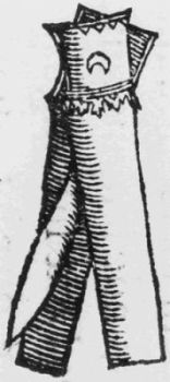
Figure 37.—Thumb lancet, 16th century. (From Leonardo Botallo, De Curatione per Sanguinis Missionem, Antwerp, 1583. Photo courtesy of NLM.)
Figure 37.—Thumb lancet, 16th century. (From Leonardo Botallo, De Curatione per Sanguinis Missionem, Antwerp, 1583. Photo courtesy of NLM.)

Figure 38.—Typical 19th-century thumb lancets, engraved “S. Maw, London.” (NMHT 139980 [M-4151]; SI photo 73-4230.)
Figure 38.—Typical 19th-century thumb lancets, engraved “S. Maw, London.” (NMHT 139980 [M-4151]; SI photo 73-4230.)

Figure 39.—Typical 19th-century brass spring lancet and case. The case is stamped “Traunichtessticht,” which translates, “Watch out, it stabs.” (NMHT 308730.10; SI photo 74-4088.)
Figure 39.—A typical brass spring lancet from the 19th century along with its case. The case is marked “Traunichtessticht,” which means, “Watch out, it stabs.” (NMHT 308730.10; SI photo 74-4088.)

Figure 40.—Spring lancets, dated 1775. (Held by Rhode Island Medical Society; SI photo 73-5762.)
Figure 40.—Spring lancets, from 1775. (Owned by the Rhode Island Medical Society; SI photo 73-5762.)

Figure 41.—Fleam, 16th century. (From Leonardo Botallo, De Curatione per Sanguinis Missionem, Antwerp, 1583. Photo courtesy of NLM.)
Figure 41.—Fleam, 16th century. (From Leonardo Botallo, De Curatione per Sanguinis Missionem, Antwerp, 1583. Photo courtesy of NLM.)

Figure 42.(top)—Hand-forged fleam with hand-carved wooden case, 17th and 18th century, Swiss or Tyrolean. (NMHT 233570 [M-9666]; SI photo 59139-E.)
Figure 42.(top)—Hand-forged fleam with a hand-carved wooden case, 17th and 18th century, Swiss or Tyrolean. (NMHT 233570 [M-9666]; SI photo 59139-E.)
Figure 43.(bottom)—Fleam made by E. Dalman, London. Note unusual curved shape to blade. (From the original in the Wellcome Museum by courtesy of the Trustees, photo L. 1346.)
Figure 43.(bottom)—Fleam made by E. Dalman, London. Note the unique curved shape of the blade. (From the original in the Wellcome Museum by courtesy of the Trustees, photo L. 1346.)

Figure 44.—Silver spring lancet in case. Case is lined with white silk and rose plush and has a gold leaf border. (NMHT 321687.02; SI photo 76-7752.)
Figure 44.—Silver spring lancet in case. The case is lined with white silk and rose plush and has a gold leaf border. (NMHT 321687.02; SI photo 76-7752.)

Figure 45.—Unusual spring lancet with extra blade, engraved “M.A. Prizzi,” 18th century. (NMHT 320033.06; SI photo 76-7763.)
Figure 45.—Unique spring lancet with an extra blade, engraved “M.A. Prizzi,” 18th century. (NMHT 320033.06; SI photo 76-7763.)

Figure 46.—Unusual spring lancet in hand-carved wooden case, 18th century. Note the large blade and blade guard regulated by a screw. (NMHT 321.697.12; SI photo 76-9114.)
Figure 46.—Unique spring lancet in a hand-carved wooden case, 18th century. Notice the large blade and the blade guard adjusted by a screw. (NMHT 321.697.12; SI photo 76-9114.)

Figure 47.—George Tiemann & Co.’s spring lancet, late 19th century. (NMHT 163863 [M-5141]; SI photo 73-5644.)
Figure 47.—George Tiemann & Co.’s spring lancet, late 19th century. (NMHT 163863 [M-5141]; SI photo 73-5644.)

Figure 48.—Patent model spring lancet, patented by J.W.W. Gordon in 1857. Back view. (NMHT 89797 [M-4298]; SI photo 73-10319.)
Figure 48.—Patent model spring lancet, patented by J.W.W. Gordon in 1857. Back view. (NMHT 89797 [M-4298]; SI photo 73-10319.)

Figure 49.—Patent model spring lancet, patented by J.W.W. Gordon in 1857. Front view. (NMHT 89797 [M-4298]; SI photo 73-10318.)
Figure 49.—Patent model spring lancet, patented by J.W.W. Gordon in 1857. Front view. (NMHT 89797 [M-4298]; SI photo 73-10318.)

Figure 50.—Wet cupping for a headache. (From Frederik Dekkers, Exercitationes Practicae Circa Medendi Methodum, Leyden, 1694. Photo courtesy of NLM.)
Figure 50.—Wet cupping for a headache. (From Frederik Dekkers, Exercitationes Practicae Circa Medendi Methodum, Leyden, 1694. Photo courtesy of NLM.)

Figure 51.—Dry cupping for sciatica. (From Frederik Dekkers, Exercitationes Practicae Circa Medendi Methodum, Leyden, 1694. Photo courtesy of NLM.)
Figure 51.—Dry cupping for sciatica. (From Frederik Dekkers, Practical Exercises on the Method of Healing, Leyden, 1694. Photo courtesy of NLM.)

Figure 52.—Horn cups used in Egypt in the 16th century. (From Prosper Alphinus, Medicina Aegyptorum, Leyden, 1719. Photo courtesy of NLM.)
Figure 52.—Horn cups used in Egypt in the 16th century. (From Prosper Alphinus, Medicina Aegyptorum, Leyden, 1719. Photo courtesy of NLM.)

Figure 53.—Horn cup used in the Niger Republic of West Africa in the 1960s. (NMHT 270023 [M-11998]; SI photo 73-5643.)
Figure 53.—Horn cup used in Niger, West Africa, during the 1960s. (NMHT 270023 [M-11998]; SI photo 73-5643.)

Figure 54.—Replica of a Greek votive tablet found in the remains of the Temple of Aesculapius. Pictured are two metal cups and a set of scalpels. (NMHT 233055 [M-9617]; SI photo 73-4217.)
Figure 54.—Replica of a Greek votive tablet discovered in the remains of the Temple of Aesculapius. It shows two metal cups and a set of scalpels. (NMHT 233055 [M-9617]; SI photo 73-4217.)

Figure 55.—Egyptian spouted cupping cups, 16th century. (From Prosper Alpinus, Medicina Aegyptorum, Leyden, 1719. Photo courtesy of NLM.)
Figure 55.—Egyptian spouted cupping cups, 16th century. (From Prosper Alpinus, Medicina Aegyptorum, Leyden, 1719. Photo courtesy of NLM.)
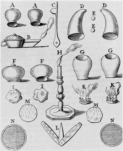
Figure 56.—Cupping instruments illustrated by Dionis, 1708: A, cups made of horn; B, lamp for exhausting air; C, fleam for making scarifications; D, horns with holes at the tip for mouth suction; E, balls of wax to close the holes in the horn cups; F, G, glass cups; H, candle to light the tow or the small candles; I, tow; K, small candles on a card which is placed over the scarifications and lit in order to exhaust the cup; L, lancet for making scarifications; M, scarifications; N, plaster to place on the wound. (From Pierre Dionis, Cours d’opérations de chirurgie demontrées au Jardin Royal, Paris, 1708. Photo courtesy of NLM.)
Figure 56.—Cupping instruments shown by Dionis, 1708: A, cups made of horn; B, lamp for removing air; C, fleam for making cuts; D, horns with holes at the tip for sucking; E, balls of wax to seal the holes in the horn cups; F, G, glass cups; H, candle to light the tow or the small candles; I, tow; K, small candles on a card placed over the cuts and lit to create suction in the cup; L, lancet for making cuts; M, cuts; N, plaster to put on the wound. (From Pierre Dionis, Cours d’opérations de chirurgie demontrées au Jardin Royal, Paris, 1708. Photo courtesy of NLM.)

Figure 57.—Teapot lamp, 18th century.
(NMHT 199536
[M-6691]; SI photo 73-4218.)
Figure 57.—Teapot lamp, 18th century.
(NMHT 199536
[M-6691]; SI photo 73-4218.)

Figure 58.—13th-century Arabic cupping scene. (From a manuscript held by the Freer Gallery. SI photo 43757-J.)
Figure 58.—13th-century Arabic cupping scene. (From a manuscript held by the Freer Gallery. SI photo 43757-J.)

Figure 59.—Paré’s scarificator, 16th century. (From The Workes of that Famous Chirurgeon, Ambrose Parey, translated by Thomas Johnson, London, 1649. Photo courtesy of NLM.)
Figure 59.—Paré’s scarificator, 16th century. (From The Workes of that Famous Chirurgeon, Ambrose Parey, translated by Thomas Johnson, London, 1649. Photo courtesy of NLM.)

Figure 60.—Square scarificator, engraved “J.T./Wien,” late 18th-early 19th century. Vienna was an early center for the making of scarificators. (NMHT 218383 [M-9257]; SI photo 73-4212.)
Figure 60.—Square scarificator, engraved “J.T./Wien,” late 18th-early 19th century. Vienna was an early hub for making scarificators. (NMHT 218383 [M-9257]; SI photo 73-4212.)

Figure 61.—An early illustration of the scarificator. Also pictured are a fleam for making scarifications, the pattern of scarifications, a metal cup, and a leech. (From Laurence Heister, A General System of Surgery, 7th edition, London, 1759. SI photo 73-4182.)
Figure 61.—An early illustration of the scarificator. Also shown are a fleam for making scarifications, the pattern of scarifications, a metal cup, and a leech. (From Laurence Heister, A General System of Surgery, 7th edition, London, 1759. SI photo 73-4182.)

Figure 62.—Square scarificator taken apart.
(NMHT 152130 [M-4771]; SI photo 76-9113.)
Figure 62.—Square scarificator disassembled.
(NMHT 152130 [M-4771]; SI photo 76-9113.)

Figure 63.—Cupping and bleeding instruments, 1780. Illustrated are spring lancets, thumb lancets, cups, a square scarificator with pointed blades, and a lamp in which animal fat was burned. Figs. 16, 17, and 18 are unrelated to bloodletting. (From J. A. Brambilla, Instrumentarium Chirurgicum Viennense, Vienna, 1780. Photo courtesy of NLM.)
Figure 63.—Cupping and bleeding instruments, 1780. This illustration shows spring lancets, thumb lancets, cups, a square scarificator with pointed blades, and a lamp used for burning animal fat. Figs. 16, 17, and 18 are not related to bloodletting. (From J. A. Brambilla, Instrumentarium Chirurgicum Viennense, Vienna, 1780. Photo courtesy of NLM.)

Figure 64.—Set of scarificator blades. Each row of blades may be inserted in place of those in need of cleaning or repair. (From the original in the Wellcome Museum by courtesy of the Trustees. Photo L. 2418.)
Figure 64.—Set of scarificator blades. Each row of blades can be swapped out for those that need cleaning or repair. (From the original in the Wellcome Museum by courtesy of the Trustees. Photo L. 2418.)

Figure 65.—An early illustration of the octagonal scarificator, 1801. This plate also includes one of the earliest illustrations of the syringe applied to cupping cups. (From Benjamin Bell, A System of Surgery, 7th edition, volume 3, Edinburgh, 1801. SI photo 73-5181.)
Figure 65.—An early illustration of the octagonal scarificator, 1801. This plate also includes one of the earliest illustrations of the syringe used with cupping cups. (From Benjamin Bell, A System of Surgery, 7th edition, volume 3, Edinburgh, 1801. SI photo 73-5181.)

Figure 66.—An unusual octagonal scarificator made by Domenico Pica in 1793. The blade cover is attached by a hinge, and the turnkey on top raises and lowers the entire interior chassis in order to regulate depth of cut. (NMHT 320033.01; SI photo 76-7742.)
Figure 66.—A unique octagonal scarificator created by Domenico Pica in 1793. The blade cover is connected by a hinge, and the knob on top raises and lowers the whole interior mechanism to adjust the cutting depth. (NMHT 320033.01; SI photo 76-7742.)

Figure 67.—Scarificator marked Domo Morett, 1813. (From the original in the Wellcome Museum, by courtesy of the Trustees. Wellcome R2909/1936; photo L 1159.)
Figure 67.—Scarificator marked Domo Morett, 1813. (From the original in the Wellcome Museum, by courtesy of the Trustees. Wellcome R2909/1936; photo L 1159.)

Figure 68.—Cupping set with base handled torch, 8 blade scarificator, 4 blade scarificator for cupping on temples, 2 cups and alcohol bottle. (NMHT, SI photo 76-9119.)
Figure 68.—Cupping set with base-handled torch, an 8-blade scarificator, a 4-blade scarificator for cupping on the temples, 2 cups, and an alcohol bottle. (NMHT, SI photo 76-9119.)

Figure 69.—Calling card, ca. 1860. (SI photo.)
Figure 69.—Business card, ca. 1860. (SI photo.)

Figure 70.—Cupping set manufactured by Charrière of Paris, mid-19th century. Note the tubing used to connect the pump to the cups, and the circular scarificator with blades cutting in opposite directions. (NMHT 302606.007; SI photo 75-090.)
Figure 70.—Cupping set made by Charrière of Paris, mid-19th century. Notice the tubing that connects the pump to the cups, and the round scarificator with blades cutting in opposite directions. (NMHT 302606.007; SI photo 75-090.)

Figure 71.—W. D. Hooper’s patent cupping apparatus with tubular blades. (From patent specifications, U.S. patent no. 68985. SI photo 73-5193.)
Figure 71.—W. D. Hooper’s patented cupping device with tubular blades. (From patent specifications, U.S. patent no. 68985. SI photo 73-5193.)
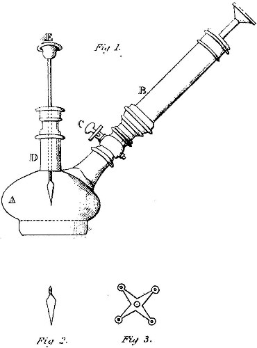
Figure 72.—Demours’ device for combining cup, scarifier and exhausting apparatus. (From Samuel Bayfield, A Treatise on Practical Cupping, London, 1823. Photo courtesy of the NLM.)
Figure 72.—Demours’ tool for merging the cup, scarifier, and suction device. (From Samuel Bayfield, A Treatise on Practical Cupping, London, 1823. Photo courtesy of the NLM.)

Figure 73.—R. J. Dodd’s patent cupping apparatus. Figs. 4 and 5 are the tubes for cupping the uterus. Fig. 3 is the flexible match scarifier. (From patent specifications, U.S. patent no. 3537. SI photo 73-5192.)
Figure 73.—R. J. Dodd’s patented cupping device. Figs. 4 and 5 show the tubes used for uterine cupping. Fig. 3 is the flexible match scarifier. (From patent specifications, U.S. patent no. 3537. SI photo 73-5192.)

Figure 74.—Circular scarificator.
(NMHT 320933.05; SI
photo 76-7746.)
Figure 74.—Circular scarificator.
(NMHT 320933.05; SI photo 76-7746.)

Figure 75.—Scarificator for vaccination. Mallam’s, made by Arnold & Sons, London. Patent 1406. (From the original in the Wellcome Museum by courtesy of the Trustees. Wellcome 13557; photo 125/1960.)
Figure 75.—Scarificator for vaccination. Mallam’s, made by Arnold & Sons, London. Patent 1406. (From the original in the Wellcome Museum by courtesy of the Trustees. Wellcome 13557; photo 125/1960.)

Figure 76.—Patent model of Tiemann’s scarificator.
(NMHT 89797 [M-4289]; SI photo 76-9115.)
Figure 76.—Patent model of Tiemann’s scarificator.
(NMHT 89797 [M-4289]; SI photo 76-9115.)

Figure 77.—Patent model of Leypoldt’s scarificator, 1847.
(NMHT 89797 [M-4290]; SI photo 73-4213.)
Figure 77.—Patent model of Leypoldt’s scarificator, 1847.
(NMHT 89797 [M-4290]; SI photo 73-4213.)

Figure 78.—Patent model of Leypoldt’s scarificator, 1851.
(NMHT 89797 [M-4293]; SI photo 76-9112.)
Figure 78.—Patent model of Leypoldt’s scarificator, 1851.
(NMHT 89797 [M-4293]; SI photo 76-9112.)

Figure 79.—Baunscheidt’s Lebenswecker, a
counter-irritation device.
(NMHT 287885 [M-12936]; SI photo 76-7751.)
Figure 79.—Baunscheidt’s Lebenswecker, a counter-irritation device.
(NMHT 287885 [M-12936]; SI photo 76-7751.)

Figure 80.—Depurator patented by A. F. Jones, 1866.
(From
patent specifications, reissue 2276. SI photo.)
Figure 80.—Purification device patented by A. F. Jones, 1866.
(From patent specifications, reissue 2276. SI photo.)

Figure 81.—Junod’s boot.
(On loan from the Armed Forces
Institute of Pathology. SI photo 73-7885.)
Figure 81.—Junod’s boot.
(On loan from the Armed Forces Institute of Pathology. SI photo 73-7885.)

Figure 82.—Woman cupping her breast. (From Maw, Son & Thompson, Surgeon’s Instruments, etc., London, 1882. SI photo 76-13540.)
Figure 82.—Woman cupping her breast. (From Maw, Son & Thompson, Surgeon’s Instruments, etc., London, 1882. SI photo 76-13540.)

Figure 83.—Glass breast pump with spout for self
application.
(NMHT 260557 [M-11467]; SI photo 76-7759.)
Figure 83.—Glass breast pump with spout for self-application.
(NMHT 260557 [M-11467]; SI photo 76-7759.)

Figure 84.—Goodyear’s patent breast pump, manufactured by the Union India Rubber Co. (NMHT 252497 [M-10510]; SI photo 76-7762.)
Figure 84.—Goodyear’s patent breast pump, made by the Union India Rubber Co. (NMHT 252497 [M-10510]; SI photo 76-7762.)

Figure 85.—Brier’s Hyperemia Apparatus, 1930s. (From Matthay Hospital Supply Co., Surgical Instruments, Los Angeles, 1937(?). SI photo.)
Figure 85.—Brier’s Hyperemia Device, 1930s. (From Matthay Hospital Supply Co., Surgical Instruments, Los Angeles, 1937(?). SI photo.)

Figure 86.—Patent for a complex cupping pump, J. A. Maxam, 1916. (From patent specifications, U.S. patent 1179129. SI photo 73-5186.)
Figure 86.—Patent for a complex cupping pump, J. A. Maxam, 1916. (From patent specifications, U.S. patent 1179129. SI photo 73-5186.)

Figure 87.—Heinrich Stern’s phlebostasis chair, 1915. (From Heinrich Stern, Theory and Practice of Bloodletting, New York, 1915. SI photo.)
Figure 87.—Heinrich Stern’s blood circulation chair, 1915. (From Heinrich Stern, Theory and Practice of Bloodletting, New York, 1915. SI photo.)

Figure 88.—Old-fashioned cupping in a German physician’s office, Chicago, Illinois, 1904. (SI photo 45726-B.)
Figure 88.—Traditional cupping in a German doctor's office, Chicago, Illinois, 1904. (SI photo 45726-B.)

Figure 89.—A man employing leeches to reduce his weight, 16th century. (From P. Boaistuau, Histoire Podigieuses, Paris, 1567. Photo courtesy of NLM.)
Figure 89.—A man using leeches to lose weight, 16th century. (From P. Boaistuau, Histoire Podigieuses, Paris, 1567. Photo courtesy of NLM.)

Figure 90.—Osborne’s instrument for inserting leeches into the rectum. (From J. Osborne, “Observations on Local Bloodletting,” Dublin Journal of Medical and Chemical Science, volume 3 (1833). Photo courtesy of NLM.)
Figure 90.—Osborne’s tool for putting leeches into the rectum. (From J. Osborne, “Observations on Local Bloodletting,” Dublin Journal of Medical and Chemical Science, volume 3 (1833). Photo courtesy of NLM.)

Figure 91.—Two leeches (Hirudo medicinalis) preserved in
plastic.
(Anthropology Catalog no. 143,077; SI photo 73-4233.)
Figure 91.—Two leeches (Hirudo medicinalis) stored in plastic.
(Anthropology Catalog no. 143,077; SI photo 73-4233.)

Figure 92.—Satire on the theories of Broussais. The caption read, “But, I haven’t a drop of blood left in my veins! No matter, another fifty leeches.” (Undated print. Photo courtesy of NLM.)
Figure 92.—Satire on the theories of Broussais. The caption read, “But I don't have any blood left in my veins! No worries, just another fifty leeches.” (Undated print. Photo courtesy of NLM.)

Figure 93.—Woman using leeches, 17th century. (From Guillaume van den Bossche, Historica Medica, Brussels, 1639. Photo courtesy of NLM.)
Figure 93.—Woman using leeches, 17th century. (From Guillaume van den Bossche, Historica Medica, Brussels, 1639. Photo courtesy of NLM.)

Figure 94.—Heurteloup’s leech. (From George Tiemann & Co., American Armamentarium Chirurgicum, New York, 1889. SI photo 76-13541.)
Figure 94.—Heurteloup’s leech. (From George Tiemann & Co., American Armamentarium Chirurgicum, New York, 1889. SI photo 76-13541.)
Figure 95.—Tiemann & Co.’s patent artificial leech. (From George Tiemann & Co., American Armamentarium Chirurgicum, New York, 1889. SI photo 76-13541.)
Figure 95.—Tiemann & Co.’s patented artificial leech. (From George Tiemann & Co., American Armamentarium Chirurgicum, New York, 1889. SI photo 76-13541.)
Figure 96.—Reese’s uterine leech. (From George Tiemann & Co., American Armamentarium Chirurgicum, New York, 1889. SI photo 76-13539.)
Figure 96.—Reese’s uterine leech. (From George Tiemann & Co., American Armamentarium Chirurgicum, New York, 1889. SI photo 76-13539.)

Figure 97.—Sarlandière’s bdellometer. Fig. 13 and Fig. 14 are a teapot lamp and a glass for measuring the blood taken in cupping. All the other figures illustrate variations on the bdellometer. Fig. 19 and Fig. 20 are attachments for bleeding the internal membranes. (From Sarlandière, “Ventouse,” Dictionnaire des sciences médicales, volume 57, 1821. Photo courtesy of NLM.)
Figure 97.—Sarlandière’s bdellometer. Fig. 13 and Fig. 14 show a teapot lamp and a glass used for measuring blood taken during cupping. All the other figures depict different versions of the bdellometer. Fig. 19 and Fig. 20 are attachments for bleeding internal membranes. (From Sarlandière, “Ventouse,” Dictionnaire des sciences médicales, volume 57, 1821. Photo courtesy of NLM.)

Figure 98.—An artificial leech. Note the three blades on the scarificator that simulate the triangular puncture of the leech. (NMHT; SI photo 76-9120.)
Figure 98.—A man-made leech. Take note of the three blades on the scarificator that mimic the triangular puncture created by a leech. (NMHT; SI photo 76-9120.)

Figure 99.—An 18th-century cutler’s illustration of veterinary instruments. Shown are a spring lancet and a fleam. Knives and hooks were often added to the bloodletting blades in foldout fleams. (From Jean Jacques Perret, L’Art du Coutelier, Paris, 1772. Photo courtesy of the NLM.)
Figure 99.—An 18th-century illustration by a cutler of veterinary instruments. It features a spring lancet and a fleam. Knives and hooks were frequently included with the bloodletting blades in foldout fleams. (From Jean Jacques Perret, L’Art du Coutelier, Paris, 1772. Photo courtesy of the NLM.)

Figure 100.—Fleam with brass shield, 18th-19th century.
(NMHT 121573 [M-3462]; SI photo 73-4206.)
Figure 100.—Fleam with brass shield, 18th-19th century.
(NMHT 121573 [M-3462]; SI photo 73-4206.)

Figure 101.—Fleam with horn shield, 19th century.
(NMHT
321697.05; SI photo 76-7758.)
Figure 101.—Fleam with horn shield, 19th century.
(NMHT 321697.05; SI photo 76-7758.)

Figure 102.—Phlebotomy knife by Rodgers & Co., London.
(Loan no. 316478; SI photo 76-9108.)
Figure 102.—Phlebotomy knife by Rodgers & Co., London.
(Loan no. 316478; SI photo 76-9108.)

Figure 103.—Unusual shaped brass spring lancet set by a sliding catch and released by a release lever. (NMHT 321697.11; SI photo 76-7754.)
Figure 103.—A uniquely shaped brass spring lancet that is secured by a sliding catch and activated by a release lever. (NMHT 321697.11; SI photo 76-7754.)

Figure 104.—Brass spring lancet that is set by pulling on the string and released by pushing upon the button. (NMHT 321697.07; SI photo 76-7750.)
Figure 104.—Brass spring lancet that is activated by pulling the string and released by pressing the button. (NMHT 321697.07; SI photo 76-7750.)

Figure 105.—Spring lancet.
(NMHT 112827; SI photo
73-4235.)
Figure 105.—Spring lancet.
(NMHT 112827; SI photo 73-4235.)

Figure 106.—Scarificator, 12 blades.
(NMHT 99749 [M-2336];
SI photo 76-7744.)
Figure 106.—Scarificator, 12 blades.
(NMHT 99749 [M-2336]; SI photo 76-7744.)

Figure 107.—Temple scarificator with case.
(NMHT 233056
[M-9639]; SI photo 76-7745.)
Figure 107.—Temple scarificator with case.
(NMHT 233056 [M-9639]; SI photo 76-7745.)

Figure 108.—Persian cupping glass, 12th century.
(NMHT 207389 [M-6836]; SI photo 73-4205.)
Figure 108.—Persian cupping glass, 12th century.
(NMHT 207389 [M-6836]; SI photo 73-4205.)

Figure 109.—Cupping cups, glass.
(NMHT 308730.09; SI photo 74-4087.)
Figure 109.—Cupping cups, glass.
(NMHT 308730.09; SI photo 74-4087.)

Figure 110.—Persian cupping cup and razor.
(NMHT 320033.07; SI photo 76-7749.)
Figure 110.—Persian cupping cup and razor.
(NMHT 320033.07; SI photo 76-7749.)

Figure 111.—Brass cup (1) and pewter cups (2). (NMHT 321697.22 and NMHT 207399 [M-6829 and M-6830]; SI photo 76-9109.)
Figure 111.—Brass cup (1) and pewter cups (2). (NMHT 321697.22 and NMHT 207399 [M-6829 and M-6830]; SI photo 76-9109.)

Figure 112.—Cupping set.
(NMHT 321697.21; SI photo 76-7747.)
Figure 112.—Cupping set.
(NMHT 321697.21; SI photo 76-7747.)

Figure 113.—Breast pump.
(NMHT 220170 [M-7435]; SI photo 76-7761.)
Figure 113.—Breast pump.
(NMHT 220170 [M-7435]; SI photo 76-7761.)

Figure 114.—Leech jar, minus top.
(NMHT 201821 [M-6712]; SI photo 73-4232.)
Figure 114.—Leech jar, without the lid.
(NMHT 201821 [M-6712]; SI photo 73-4232.)

Figure 115.—Staffordshire leech jars. (NMHT 321697.18 & .19; SI photo 76-7765.)
Figure 115.—Staffordshire leech jars. (NMHT 321697.18 & .19; SI photo 76-7765.)
Figure 116.—Leech cage. (NMHT 1977.0576.02; SI photo 77-13984.)
Figure 116.—Leech cage. (NMHT 1977.0576.02; SI photo 77-13984.)

Figure 117.—Veterinary fleam. (NMHT 218383 [M-9255]; SI photo 61125-A.)
Figure 117.—Veterinary fleam. (NMHT 218383 [M-9255]; SI photo 61125-A.)
Figure 118.—Veterinary fleam. (NMHT 233570 [M-9665]; SI photo 59139-H.)
Figure 118.—Veterinary fleam. (NMHT 233570 [M-9665]; SI photo 59139-H.)

Figure 119.—Veterinary spring lancet. (NMHT 321697.08; SI photo 76-7756.)
Figure 119.—Veterinary spring lancet. (NMHT 321697.08; SI photo 76-7756.)
Figure 120.—Veterinary spring lancet. (NMHT 321697.09; SI photo 76-7755.)
Figure 120.—Veterinary spring lancet. (NMHT 321697.09; SI photo 76-7755.)

Figure 121.—Spring lancet, 18th century.
(NMHT 321697.10; SI photo 76-7753.)
Figure 121.—Spring lancet, 18th century.
(NMHT 321697.10; SI photo 76-7753.)

Figure 122.—Spring lancet, 19th century.
(NMHT 1977.0576.01; SI photo 77-13961.)
Figure 122.—Spring lancet, 19th century.
(NMHT 1977.0576.01; SI photo 77-13961.)

Figure 123.—Counter-irritation device.
(NMHT 89797 [M-4305]; SI photo 72-11274.)
Figure 123.—Counter-irritation device.
(NMHT 89797 [M-4305]; SI photo 72-11274.)

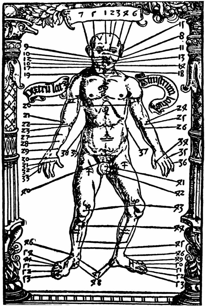
Figure 124.—Barber surgeon’s set, 18th century.
(NMHT 199536 [M-6684-6692]; SI photo 73-4207.)
Figure 124.—Barber surgeon’s set, 18th century.
(NMHT 199536 [M-6684-6692]; SI photo 73-4207.)
REQUIREMENTS FOR SMITHSONIAN SERIES PUBLICATION
Manuscripts intended for series publication receive substantive review within their originating Smithsonian museums or offices and are submitted to the Smithsonian Institution Press with approval of the appropriate museum authority on Form SI-36. Requests for special treatment—use of color, foldouts, casebound covers, etc.—require, on the same form, the added approval of designated committees or museum directors.
Manuscripts intended for series publication undergo a thorough review at their respective Smithsonian museums or offices before being submitted to the Smithsonian Institution Press with the approval of the relevant museum authority on Form SI-36. Any requests for special treatment—like the use of color, foldouts, casebound covers, etc.—must also get additional approval from designated committees or museum directors on the same form.
Review of manuscripts and art by the Press for requirements of series format and style, completeness and clarity of copy, and arrangement of all material, as outlined below, will govern, within the judgment of the Press, acceptance or rejection of the manuscripts and art.
Review of manuscripts and artwork by the Press for adherence to the series format and style, the completeness and clarity of the text, and the organization of all materials, as detailed below, will determine, at the Press's discretion, whether the manuscripts and artwork are accepted or rejected.
Copy must be typewritten, double-spaced, on one side of standard white bond paper, with 1¼″ margins, submitted as ribbon copy (not carbon or xerox), in loose sheets (not stapled or bound), and accompanied by original art. Minimum acceptable length is 30 pages.
Copy must be typed, double-spaced, on one side of standard white bond paper, with 1¼″ margins, submitted as original copy (not carbon or xerox), in loose sheets (not stapled or bound), and accompanied by original art. The minimum acceptable length is 30 pages.
Front matter (preceding the text) should include: title page with only title and author and no other information, abstract page with author/title/series/etc., following the established format, table of contents with indents reflecting the heads and structure of the paper.
Front matter (before the text) should include: title page with just the title and author, with no other information, abstract page containing author/title/series/etc., following the standard format, table of contents with indents that show the headings and structure of the paper.
First page of text should carry the title and author at the top of the page and an unnumbered footnote at the bottom consisting of author’s name and professional mailing address.
First page of text should feature the title and author at the top of the page, with an unnumbered footnote at the bottom that includes the author's name and professional mailing address.
Center heads of whatever level should be typed with initial caps of major words, with extra space above and below the head, but with no other preparation (such as all caps or underline). Run-in paragraph heads should use period/dashes or colons as necessary.
Center heads of any level should be capitalized for the main words, with extra space above and below the head, but without any other formatting (like all caps or underline). Run-in paragraph heads should use periods/dashes or colons as needed.
Tabulations within text (lists of data, often in parallel columns) can be typed on the text page where they occur, but they should not contain rules or formal, numbered table heads.
Tabulations within text (lists of data, often in parallel columns) can be typed on the text page where they occur, but they should not contain lines or formal, numbered table headings.
Formal tables (numbered, with table heads, boxheads, stubs, rules) should be submitted as camera copy, but the author must contact the series section of the Press for editorial attention and preparation assistance before final typing of this matter.
Formal tables (numbered, with table headers, box heads, stubs, and rules) should be submitted as camera-ready copies, but the author must reach out to the series section of the Press for editorial support and preparation help before finalizing this material.
Taxonomic keys in natural history papers should use the alined-couplet form in the zoology and paleobiology series and the multi-level indent form in the botany series. If cross-referencing is required between key and text, do not include page references within the key, but number the keyed-out taxa with their corresponding heads in the text.
Taxonomic keys in natural history papers should use the aligned-couplet format in the zoology and paleobiology series, and the multi-level indent format in the botany series. If cross-referencing is needed between the key and the text, do not include page references within the key; instead, number the keyed-out taxa with their corresponding headings in the text.
Synonymy in the zoology and paleobiology series must use the short form (taxon, author, year:page), with a full reference at the end of the paper under “Literature Cited.” For the botany series, the long form (taxon, author, abbreviated journal or book title, volume, page, year, with no reference in the “Literature Cited”) is optional.
Synonymy in the zoology and paleobiology series must follow the short form (taxon, author, year:page), with a complete reference listed at the end of the paper under “Literature Cited.” For the botany series, the long form (taxon, author, abbreviated journal or book title, volume, page, year, with no reference in the “Literature Cited”) is optional.
Footnotes, when few in number, whether annotative or bibliographic, should be typed at the bottom of the text page on which the reference occurs. Extensive notes must appear at the end of the text in a notes section. If bibliographic footnotes are required, use the short form (author/brief title/page) with the full reference in the bibliography.
Footnotes, when limited in number, whether they are for annotations or bibliographic citations, should be typed at the bottom of the text page where the reference is found. For extensive notes, these should be placed at the end of the text in a notes section. If bibliographic footnotes are needed, use the short form (author/brief title/page) and include the full reference in the bibliography.
Text-reference system (author/year/page within the text, with the full reference in a “Literature Cited” at the end of the text) must be used in place of bibliographic footnotes in all scientific series and is strongly recommended in the history and technology series: “(Jones, 1910:122)” or “... Jones (1910:122).”
Text-reference system (author/year/page within the text, with the full reference in a “Literature Cited” at the end of the text) must be used instead of bibliographic footnotes in all scientific series and is highly recommended in the history and technology series: “(Jones, 1910:122)” or “... Jones (1910:122).”
Bibliography, depending upon use, is termed “References,” “Selected References,” or “Literature Cited.” Spell out book, journal, and article titles, using initial caps in all major words. For capitalization of titles in foreign languages, follow the national practice of each language. Underline (for italics) book and journal titles. Use the colon-parentheses system for volume/number/page citations: “10(2):5-9.” For alinement and arrangement of elements, follow the format of the series for which the manuscript is intended.
Bibliography can be referred to as “References,” “Selected References,” or “Literature Cited,” depending on how it’s used. Write out book, journal, and article titles, capitalizing all major words. For titles in foreign languages, use the capitalization style typical of that language. Underline (to indicate italics) book and journal titles. Use the colon-parentheses format for volume/number/page citations: “10(2):5-9.” When aligning and arranging elements, follow the formatting style specific to the series for which the manuscript is intended.
Legends for illustrations must not be attached to the art nor included within the text but must be submitted at the end of the manuscript—with as many legends typed, double-spaced, to a page as convenient.
Legends for illustrations shouldn't be attached to the artwork or included in the text but should be submitted at the end of the manuscript—typed double-spaced, with as many legends per page as is convenient.
Illustrations must not be included within the manuscript but must be submitted separately as original art (not copies). All illustrations (photographs, line drawings, maps, etc.) can be intermixed throughout the printed text. They should be termed Figures and should be numbered consecutively. If several “figures” are treated as components of a single larger figure, they should be designated by lowercase italic letters (underlined in copy) on the illustration, in the legend, and in text references: “Figure 9b.” If illustrations are intended to be printed separately on coated stock following the text, they should be termed Plates and any components should be lettered as in figures: “Plate 9b.” Keys to any symbols within an illustration should appear on the art and not in the legend.
Illustrations should not be included in the manuscript but must be submitted separately as original artwork (not copies). All illustrations (photographs, line drawings, maps, etc.) can be mixed throughout the printed text. They should be called Figures and numbered consecutively. If several “figures” are part of a single larger figure, they should be designated with lowercase italic letters (underlined in the copy) on the illustration, in the legend, and in text references: “Figure 9b.” If illustrations are meant to be printed separately on coated paper after the text, they should be called Plates, and any components should be labeled as in figures: “Plate 9b.” Keys to any symbols within an illustration should be included on the art itself and not in the legend.
A few points of style: (1) Do not use periods after such abbreviations as “mm, ft, yds, USNM, NNE, AM, BC.” (2) Use hyphens in spelled-out fractions: “two-thirds.” (3) Spell out numbers “one” through “nine” in expository text, but use numerals in all other cases if possible. (4) Use the metric system of measurement, where possible, instead of the English system. (5) Use the decimal system, where possible, in place of fractions. (6) Use day/month/year sequence for dates: “9 April 1976.” (7) For months in tabular listings or data sections, use three-letter abbreviations with no periods: “Jan, Mar, Jun,” etc.
A few points of style: (1) Don’t use periods after abbreviations like “mm, ft, yds, USNM, NNE, AM, BC.” (2) Use hyphens in written-out fractions: “two-thirds.” (3) Spell out numbers “one” through “nine” in regular text, but use numerals in all other situations if possible. (4) Use the metric system instead of the English system whenever possible. (5) Use the decimal system instead of fractions when you can. (6) Use the day/month/year format for dates: “9 April 1976.” (7) For months in tables or data sections, use three-letter abbreviations without periods: “Jan, Mar, Jun,” etc.
Arrange and paginate sequentially EVERY sheet of manuscript—including ALL front matter and ALL legends, etc., at the back of the text—in the following order: (1) title page, (2) abstract, (3) table of contents, (4) foreword and/or preface, (5) text, (6) appendixes, (7) notes, (8) glossary, (9) bibliography, (10) index, (11) legends.
Arrange and paginate every sheet of the manuscript sequentially—including all front matter and all legends, etc., at the back of the text—in this order: (1) title page, (2) abstract, (3) table of contents, (4) foreword and/or preface, (5) text, (6) appendices, (7) notes, (8) glossary, (9) bibliography, (10) index, (11) legends.
Transcriber’s Notes:
Transcriber's Notes:
Images have been moved from the middle of a paragraph to the closest paragraph break. Thus, page numbering around the images within the text does not exactly match the original.
Images have been shifted from the center of a paragraph to the nearest paragraph break. As a result, the page numbering around the images in the text doesn't match the original exactly.
The text in the Table of Contents is presented as in the original text, but the links navigate to the page number closest to the item’s loaction in this document.
The text in the Table of Contents is presented as in the original text, but the links navigate to the page number closest to the item's location in this document.
Punctuation has been corrected without note.
Punctuation has been fixed without comment.
Other than the corrections noted by hover information, printer’s inconsistencies in spelling and hyphenation have been retained.
Other than the corrections mentioned in the hover information, inconsistencies in spelling and hyphenation from the printer have been kept.
Download ePUB
If you like this ebook, consider a donation!