This is a modern-English version of Steam Engines, originally written by Anonymous.
It has been thoroughly updated, including changes to sentence structure, words, spelling,
and grammar—to ensure clarity for contemporary readers, while preserving the original spirit and nuance. If
you click on a paragraph, you will see the original text that we modified, and you can toggle between the two versions.
Scroll to the bottom of this page and you will find a free ePUB download link for this book.
E-text prepared by Chris Curnow, Harry Lamé,
and the Online Distributed Proofreading Team
(http://www.pgdp.net)
from page images generously made available by
Internet Archive
(http://www.archive.org)
| Note: | Images of the original pages are available through Internet Archive. See http://www.archive.org/details/steamengines00newyrich |
MACHINERY’S REFERENCE SERIES
EACH NUMBER IS A UNIT IN A SERIES ON ELECTRICAL AND
STEAM ENGINEERING DRAWING AND MACHINE
DESIGN AND SHOP PRACTICE
EACH NUMBER IS A UNIT IN A SERIES ON ELECTRICAL AND
STEAM ENGINEERING DRAWING AND MACHINE
DESIGN AND SHOP PRACTICE
NUMBER 70
STEAM ENGINES
CONTENTS
| Action of Steam Engines | 3 |
| Rating and General Proportions of Steam Engines | 11 |
| Steam Engine Details | 15 |
| Steam Engine Economy | 30 |
| Types of Steam Engines | 36 |
| Steam Engine Testing | 41 |
Copyright, 1911, The Industrial Press, Publishers of Machinery,
49-55 Lafayette Street, New York City.
Copyright, 1911, The Industrial Press, Publishers of Machinery,
49-55 Lafayette Street, New York City.
CHAPTER I
ACTION OF STEAM ENGINES
A steam engine is a device by means of which heat is transformed into work. Work may be defined as the result produced by a force acting through space, and is commonly measured in foot-pounds; a foot-pound represents the work done in raising 1 pound 1 foot in height. The rate of doing work is called power. It has been found by experiment that there is a definite relation between heat and work, in the ratio of 1 thermal unit to 778 foot-pounds of work. The number 778 is commonly called the heat equivalent of work or the mechanical equivalent of heat.
A steam engine is a device that converts heat into work. Work can be defined as the outcome produced by a force acting over a distance and is usually measured in foot-pounds; a foot-pound refers to the work done in lifting 1 pound a height of 1 foot. The speed at which work is done is known as power. Experiments have shown that there is a specific relationship between heat and work, with a ratio of 1 thermal unit to 778 foot-pounds of work. The number 778 is often referred to as the heat equivalent of work or the mechanical equivalent of heat.
Heat may be transformed into mechanical work through the medium of steam, by confining a given amount in a closed chamber, and then allowing it to expand by means of a movable wall (piston) fitted into one side of the chamber. Heat is given up in the process of expansion, as shown by the lowered pressure and temperature of the steam, and work has been done in moving the wall (piston) of the closed chamber against a resisting force or pressure. When the expansion of steam takes place without the loss of heat by radiation or conduction, the relation between the pressure and volume is practically constant; that is, if a given quantity of steam expands to twice its volume in a closed chamber of the kind above described, its final pressure will be one-half that of the initial pressure before expansion took place. A pound of steam at an absolute pressure of 20 pounds per square inch has a volume of practically 20 cubic feet, and a temperature of 228 degrees. If now it be expanded so that its volume is doubled (40 cubic feet), the pressure will drop to approximately 10 pounds per square inch and the temperature will be only about 190 degrees. The drop in temperature is due to the loss of heat which has been transformed into work in the process of expansion and in moving the wall (piston) of the chamber against a resisting force, as already noted.
Heat can be converted into mechanical work using steam by trapping a specific amount in a sealed chamber and then letting it expand through a movable wall (piston) that fits into one side of the chamber. During this expansion, heat is released, indicated by the drop in pressure and temperature of the steam, and work is done by moving the wall (piston) of the chamber against an external force or pressure. When steam expands without losing heat through radiation or conduction, the relationship between pressure and volume remains nearly constant; in other words, if a certain amount of steam doubles its volume in a closed chamber as described, its final pressure will be half of the initial pressure before expansion. A pound of steam at an absolute pressure of 20 pounds per square inch has a volume of about 20 cubic feet and a temperature of 228 degrees. If it expands to double its volume (40 cubic feet), the pressure will drop to around 10 pounds per square inch, and the temperature will decrease to about 190 degrees. This temperature drop happens because heat has been turned into work during the expansion and while moving the wall (piston) against a resisting force, as mentioned earlier.
Principle of the Steam Engine
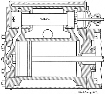
The steam engine makes use of a closed chamber with a movable wall in transforming the heat of steam into mechanical work in the manner just described. Fig. 1 shows a longitudinal section through an engine of simple design, and illustrates the principal parts and their relation to one another.
The steam engine uses a closed chamber with a movable wall to convert steam heat into mechanical work as described. Fig. 1 shows a side view of a simply designed engine and illustrates the main parts and how they relate to each other.
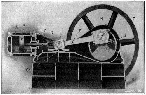
Fig. 1. Longitudinal Section through the Ames High-speed Engine
Fig. 1. Longitudinal Section through the Ames High-speed Engine
The cylinder A is the closed chamber in which expansion takes place, and the piston B, the movable wall. The cylinder is of cast iron, accurately bored and finished to a circular cross-section. The piston is carefully fitted to slide easily in the cylinder, being made practically steam tight by means of packing rings. The work generated in moving the piston is transferred to the crank-pin H by means[4] of the piston-rod C, and the connecting-rod F. The piston-rod passes out of the cylinder through a stuffing box, which prevents the leakage of steam around it. The cross-head D serves to guide the piston-rod in a straight line, and also contains the wrist-pin E which joins the piston-rod and connecting-rod. The cross-head slides upon the guide-plate G, which causes it to move in an accurate line, and at the same time takes the downward thrust from the connecting-rod.
The cylinder A is the enclosed space where expansion happens, and the piston B acts as the movable wall. The cylinder is made of cast iron, precisely bored and finished to have a circular cross-section. The piston is carefully designed to slide smoothly within the cylinder, being made almost completely steam-tight with packing rings. The work produced by moving the piston is transferred to the crank-pin H via the piston-rod C and the connecting-rod F. The piston-rod extends out of the cylinder through a stuffing box, which stops steam from leaking around it. The cross-head D helps guide the piston-rod in a straight line and also holds the wrist-pin E that connects the piston-rod and connecting-rod. The cross-head slides along the guide-plate G, which ensures it moves in a precise line while also absorbing the downward force from the connecting-rod.
The crank-pin is connected with the main shaft I by means of a crank arm, which in this case is made in the form of a disk in order to give a better balance. The balance wheel or flywheel J carries the crank past the dead centers at the ends of the stroke, and gives a uniform motion to the shaft. The various parts of the engine are carried on a rigid bed K, usually of cast iron, which in turn is bolted to a foundation of brick or concrete. The power developed is taken off by means of a belted pulley attached to the main shaft, or, in certain cases, in the form of electrical energy from a direct-connected dynamo.
The crank-pin connects to the main shaft I through a crank arm, which is shaped like a disk for better balance. The balance wheel or flywheel J moves the crank past the dead centers at the ends of the stroke, ensuring smooth motion of the shaft. The different parts of the engine are mounted on a sturdy bed K, usually made of cast iron, which is bolted to a brick or concrete foundation. The power produced is harnessed through a belted pulley attached to the main shaft, or, in some cases, as electrical energy from a directly connected dynamo.
When in action, a certain amount of steam (1⁄4 to 1⁄3 of the total cylinder volume in simple engines) is admitted to one end of the cylinder, while the other is open to the atmosphere. The steam forces the piston forward a certain distance by its direct action at the boiler pressure. After the supply is shut off, the forward movement of the piston is continued to the end of the stroke by the expansion of the steam. Steam is now admitted to the other end of the cylinder, and the operation repeated on the backward or return stroke.
When in operation, a certain amount of steam (1⁄4 to 1⁄3 of the total cylinder volume in simple engines) is released into one end of the cylinder, while the other end is open to the atmosphere. The steam pushes the piston forward a certain distance due to the boiler pressure. After the steam supply is cut off, the piston continues moving forward until the end of the stroke because of the steam's expansion. Then, steam is let into the other end of the cylinder, and the process is repeated on the backward or return stroke.
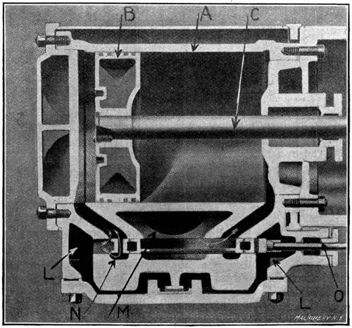
An enlarged section of the cylinder showing the action of the valve for admitting and exhausting the steam is shown in Fig. 2. In this case the piston is shown in its extreme backward position, ready for the forward stroke. The steam chest L is filled with steam at boiler pressure, which is being admitted to the narrow space back of the piston through the valve N, as indicated by the arrows. The exhaust port M is in communication with the other end of the cylinder and[5] allows the piston to move forward without resistance, except that due to the piston-rod, which transfers the work done by the expanding steam to the crank-pin. The valve N is operated automatically by a crank or eccentric attached to the main shaft, and opens and closes the supply and exhaust ports at the proper time to secure the results described.
An enlarged section of the cylinder showing how the valve works for entering and releasing the steam is shown in Fig. 2. Here, the piston is shown in its farthest backward position, ready for the forward stroke. The steam chest L is filled with steam at boiler pressure, which is being let into the narrow space behind the piston through the valve N, as indicated by the arrows. The exhaust port M connects to the other end of the cylinder and[5] allows the piston to move forward without resistance, except for that caused by the piston rod, which transfers the work done by the expanding steam to the crank pin. The valve N is automatically operated by a crank or eccentric attached to the main shaft, and it opens and closes the supply and exhaust ports at the right times to achieve the results described.
Work Diagram
Having discussed briefly the general principle upon which an engine operates, the next step is to study more carefully the transformation of heat into work within the cylinder, and to become familiar with the graphical methods of representing it. Work has already been defined as the result of force acting through space, and the unit of work as the foot-pound, which is the work done in raising 1 pound 1 foot in height. For example, it requires 1 × 1 = 1 foot-pound to raise 1 pound 1 foot, or 1 × 10 = 10 foot-pounds to raise 1 pound 10 feet, or 10 × 1 = 10 foot-pounds to raise 10 pounds 1 foot, or 10 × 10 = 100 foot-pounds to raise 10 pounds 10 feet, etc. That is, the product of weight or force acting, times the distance moved through, represents work; and if the force is taken in pounds and the distance in feet, the result will be in foot-pounds. This result may be shown graphically by a figure called a work diagram.
Having briefly discussed the basic principle of how an engine works, the next step is to take a closer look at how heat is converted into work within the cylinder and to understand the graphical methods used to represent this. Work has already been defined as the outcome of force acting over a distance, with the unit of work being the foot-pound, which is the work done in lifting 1 pound a distance of 1 foot. For instance, it takes 1 × 1 = 1 foot-pound to lift 1 pound 1 foot, or 1 × 10 = 10 foot-pounds to lift 1 pound 10 feet, or 10 × 1 = 10 foot-pounds to lift 10 pounds 1 foot, or 10 × 10 = 100 foot-pounds to lift 10 pounds 10 feet, and so on. In other words, the product of the weight or force applied multiplied by the distance moved represents work; and if the force is measured in pounds and the distance in feet, the result will be in foot-pounds. This result can be illustrated graphically with a figure known as a work diagram.
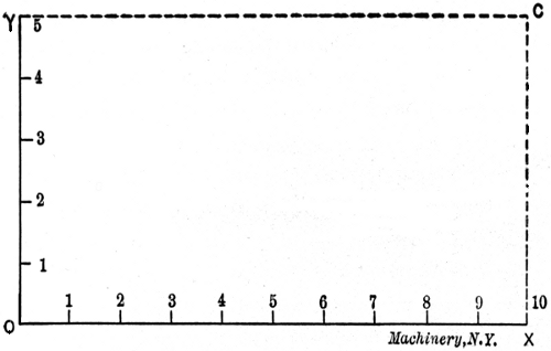
In Fig. 3, let distances on the line OY represent the force acting, and distances on OX represent the space moved through. Suppose the figure to be drawn to such a scale that OY is 5 feet in height, and OX 10 feet long. Let each division on OY represent 1 pound pressure, and[6] each division on OX 1 foot of space moved through. If a pressure of 5 pounds acts through a distance of 10 feet, then an amount of 5 × 10 = 50 foot-pounds of work has been done. Referring to Fig. 3, it is evident that the height OY (the pressure acting), multiplied by the length OX (the distance moved through), gives 5 × 10 = 50 square feet, which is the area of the rectangle YCXO; that is, the area of a rectangle may represent work done, if the height represents a force acting, and the length the distance moved through. If the diagram were drawn to a smaller scale so that the divisions were 1 inch in length instead of 1 foot, the area YCXO would still represent the work done, except each square inch would equal 1 foot-pound instead of each square foot, as in the present illustration.
In Fig. 3, let the distances on the line OY represent the force applied, and the distances on OX represent the distance traveled. Assume the figure is drawn to a scale where OY is 5 feet tall, and OX is 10 feet long. Each division on OY will represent 1 pound of pressure, and [6] each division on OX will equal 1 foot of distance. If a pressure of 5 pounds acts over a distance of 10 feet, then the total work done would be 5 × 10 = 50 foot-pounds. Referring to Fig. 3, it's clear that the height OY (the applied pressure), multiplied by the length OX (the distance moved), equals 5 × 10 = 50 square feet, which is the area of the rectangle YCXO; this means the area of a rectangle can represent work done, provided the height represents the force applied and the length represents the distance moved. If the diagram were drawn on a smaller scale with divisions of 1 inch instead of 1 foot, the area YCXO would still show the work done, but each square inch would equal 1 foot-pound instead of each square foot, as in this current example.
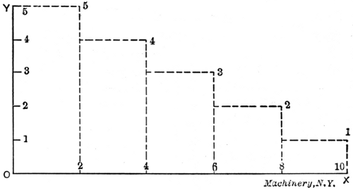
In Fig. 4 the diagram, instead of being rectangular in form, takes a different shape on account of different forces acting at different periods over the distance moved through. In the first case (Fig. 3), a uniform force of 5 pounds acts through a distance of 10 feet, and produces 5 × 10 = 50 foot-pounds of work. In the second case (Fig. 4), forces of 5 pounds, 4 pounds, 3 pounds, 2 pounds, and 1 pound, act through distances of 2 feet each, and produce (5 × 2) + (4 × 2) + (3 × 2) + (2 × 2) + (1 × 2) = 30 foot-pounds. This is also the area, in square feet, of the figure Y54321XO, which is made up of the areas of the five small rectangles shown by the dotted lines. Another way of finding the total area of the figure shown in Fig. 4, and determining the work[7] done, is to multiply the length by the average of the heights of the small rectangles. The average height is found by adding the several heights and dividing the sum by their number, as follows:
In Fig. 4 the diagram isn't rectangular; it takes a different shape because different forces act at different times over the distance covered. In the first case (Fig. 3), a constant force of 5 pounds is applied over a distance of 10 feet, resulting in 5 × 10 = 50 foot-pounds of work. In the second case (Fig. 4), forces of 5 pounds, 4 pounds, 3 pounds, 2 pounds, and 1 pound act over distances of 2 feet each, producing (5 × 2) + (4 × 2) + (3 × 2) + (2 × 2) + (1 × 2) = 30 foot-pounds. This area is also represented, in square feet, by the figure Y54321XO, which consists of the areas of the five small rectangles shown by the dotted lines. Another way to find the total area of the figure in Fig. 4 and calculate the work done is by multiplying the length by the average height of the small rectangles. The average height is determined by adding the various heights and dividing the total by the number of heights, as follows:
| 5 + 4 + 3 + 2 + 1 | |
| ——————— | = 3, and 3 × 10 = 30 square feet, as before. |
| 5 |
This, then, means that the average force acting throughout the stroke is 3 pounds, and the total work done is 3 × 10 = 30 foot-pounds.
This means that the average force applied during the stroke is 3 pounds, and the total work done is 3 × 10 = 30 foot-pounds.
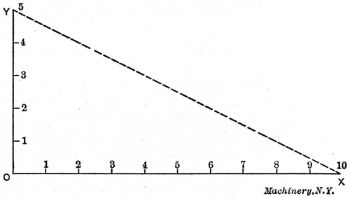
Fig. 5. Work Diagram when Pressure drops Uniformly
Fig. 5. Work Diagram when Pressure Decreases Uniformly
In Fig. 5 the pressure drops uniformly from 5 pounds at the beginning to 0 at the end of the stroke. In this case also the area and work done are found by multiplying the length of the diagram by the average height, as follows:
In Fig. 5 the pressure decreases evenly from 5 pounds at the start to 0 at the end of the stroke. In this case, the area and work done are determined by multiplying the length of the diagram by the average height, as follows:
| 5 + 0 | |
| ——— | × 10 = 25 square feet, |
| 2 |
or 25 foot-pounds of work done.
or 25 foot-pounds of work done.
The object of Figs. 3, 4 and 5 is to show how foot-pounds of work may be represented graphically by the areas of diagrams, and also to make it clear that this remains true whatever the form of the diagram. It is also evident that knowing the area, the average height or pressure may be found by dividing by the length, and vice versa.
The purpose of Figs. 3, 4 and 5 is to demonstrate how foot-pounds of work can be visually represented by the areas of diagrams, and to clarify that this is valid regardless of the diagram's shape. It's also clear that if you know the area, you can find the average height or pressure by dividing by the length, and vice versa.
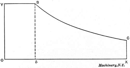
Fig. 6 shows the form of work diagram which would be produced by the action of the steam in an engine cylinder, if no heat were lost by conduction and radiation. Starting with the piston in the position shown in Fig. 2, steam is admitted at a pressure represented by the height of the line OY. As the piston moves forward, sufficient steam is admitted to maintain the same pressure. At the point B the valve closes and steam is cut off. The work done up to this time is shown by the rectangle YBbO. From the point B to the end of the stroke C, the piston is moved forward by the expansion of the steam, the pressure falling in proportion to the distance moved through, until at the end of the stroke it is represented by the vertical line CX. At the point C the exhaust valve opens and the pressure drops to 0 (atmospheric pressure in this case).
Fig. 6 shows the work diagram that would result from the steam action in an engine cylinder if there were no heat loss through conduction and radiation. Starting with the piston in the position shown in Fig. 2, steam enters at a pressure represented by the height of the line OY. As the piston moves forward, enough steam is added to keep the pressure constant. At point B, the valve closes and steam is cut off. The work done up to this point is shown by the rectangle YBbO. From point B to the end of the stroke C, the piston moves forward due to the steam expanding, with the pressure decreasing in proportion to the distance traveled, until at the end of the stroke it's represented by the vertical line CX. At point C, the exhaust valve opens and the pressure drops to 0 (which is atmospheric pressure in this case).
As it is always desirable to find the work done by a complete stroke of the engine, it is necessary to find the average or mean pressure [8]acting throughout the stroke. This can only be done by determining the area of the diagram and dividing by the length of the stroke. This gives what is called the mean ordinate, which multiplied by the scale of the drawing, will give the mean or average pressure. For example, if the area of the diagram is found to be 6 square inches, and its length is 3 inches, the mean ordinate will be 6 ÷ 3 = 2 inches. If the diagram is drawn to such a scale that 1 inch on OY represents 10 pounds, then the average or mean pressure will be 2 × 10 = 20 pounds, and this multiplied by the actual length of the piston stroke will give the work done in foot-pounds. The practical application of the above, together with the method of obtaining steam engine indicator diagrams and measuring the areas of the same, will be taken up in detail under the heading of Steam Engine Testing.
To find the work done by a complete stroke of the engine, it's important to determine the average or mean pressure [8]acting throughout the stroke. This is achieved by calculating the area of the diagram and dividing it by the length of the stroke. The result is known as the mean ordinate, which, when multiplied by the scale of the drawing, provides the mean or average pressure. For instance, if the area of the diagram is 6 square inches and its length is 3 inches, the mean ordinate will be 6 ÷ 3 = 2 inches. If the diagram is drawn to a scale where 1 inch on OY represents 10 pounds, then the average or mean pressure will be 2 × 10 = 20 pounds. Multiplying this by the actual length of the piston stroke will give the work done in foot-pounds. The practical application of this method, along with how to obtain steam engine indicator diagrams and measure their areas, will be covered in detail under the section on Steam Engine Testing.
Definitions Relating to Engine Diagrams
Before taking up the construction of an actual engine diagram, it is first necessary to become familiar with certain terms which are used in connection with it.
Before starting to create an actual engine diagram, it's essential to understand some terms that are used with it.
Cut-off.—The cut-off is the point in the stroke at which the admission valve closes and the expansion of steam begins.
Cut-off.—The cut-off is the moment in the stroke when the admission valve closes and steam expansion starts.
Ratio of Expansion.—This is the reciprocal of the cut-off, that is, if the cut-off is 1⁄4, the ratio of expansion is 4. In other words, it is the ratio of the final volume of the steam at the end of the stroke to its volume at the point of cut-off. For example, a cylinder takes steam at boiler pressure until the piston has moved one-fourth the length of its stroke; the valve now closes and expansion takes place until the stroke is completed. The one-fourth cylinderful of steam has become a cylinderful, that is, it has expanded to four times its original volume, and the ratio of expansion is said to be 4.
Ratio of Expansion.—This is the reciprocal of the cut-off, which means if the cut-off is 1⁄4, the ratio of expansion is 4. In other words, it’s the ratio of the final volume of steam at the end of the stroke to its volume at the point of cut-off. For example, a cylinder takes in steam at boiler pressure until the piston has moved one-fourth the length of its stroke; then the valve closes and expansion happens until the stroke is complete. The one-fourth cylinderful of steam has expanded to a full cylinderful, meaning it has increased to four times its original volume, and the ratio of expansion is referred to as 4.
Point of Release.—This is the point in the stroke at which the exhaust valve opens and relieves the pressure acting on the piston. This takes place just before the end of the stroke in order to reduce the shock when the piston changes its direction of travel.
Point of Release.—This is the point in the stroke where the exhaust valve opens and releases the pressure on the piston. This happens just before the end of the stroke to lessen the jolt when the piston changes direction.
Compression.—This acts in connection with the premature release in order to reduce the shock at the end of the stroke. During the forward stroke of an engine the exhaust valve in front of the piston remains open as shown in Fig. 2. Shortly before the end of the stroke[9] this closes, leaving a certain amount of steam in the cylinder. The continuation of the stroke compresses this steam, and by raising its pressure forms a cushion, which, in connection with the removal of the pressure back of the piston by release, brings the piston to a stop and causes it to reverse its direction without shock. High-speed engines require a greater amount of compression than those running at low speed.
Compression.—This works with the early release to reduce the shock at the end of the stroke. During the engine's forward stroke, the exhaust valve in front of the piston stays open as shown in Fig. 2. Just before the stroke ends[9], it closes, trapping a certain amount of steam in the cylinder. Continuing the stroke compresses this steam, raising its pressure and creating a cushion that, along with relieving the pressure behind the piston by releasing, stops the piston and makes it reverse direction smoothly. High-speed engines need more compression than those that run at low speed.
Clearance.—This is the space between the cylinder head and the piston when the latter is at the end of its stroke; it also includes that portion of the steam port between the valve and the cylinder. Clearance is usually expressed as a percentage of the piston-displacement of the cylinder, and varies in different types of engines. The following table gives approximate values for engines of different design.
Clearance.—This is the distance between the cylinder head and the piston when the piston is at the end of its stroke; it also includes the section of the steam port between the valve and the cylinder. Clearance is typically shown as a percentage of the piston displacement of the cylinder and varies in different types of engines. The following table provides approximate values for engines of different designs.
| TABLE I. CLEARANCE OF STEAM ENGINES | |||
| Type of Engine | Per Cent Clearance | ||
| Corliss | 1.5 | to | 3.5 |
| Moderate-speed | 3 | to | 8 |
| High-speed | 4 | to | 10 |
A large clearance is evidently objectionable because it represents a space which must be filled with steam at boiler pressure at the beginning of each stroke, and from which but a comparatively small amount of work is obtained. As compression increases, the amount of steam required to fill the clearance space diminishes, but on the other hand, increasing the compression reduces the mean effective pressure.
A large clearance is clearly undesirable because it creates a space that must be filled with steam at boiler pressure at the start of each stroke, from which only a small amount of work is produced. As compression increases, the amount of steam needed to fill the clearance space decreases, but on the flip side, raising the compression lowers the mean effective pressure.
Initial Pressure.—This is the pressure in the cylinder up to the point of cut-off. It is usually slightly less than boiler pressure owing to “wire-drawing” in the steam pipe and ports.
Initial Pressure.—This is the pressure in the cylinder up to the cut-off point. It's usually a bit lower than the boiler pressure due to "wire-drawing" in the steam pipe and ports.
Terminal Pressure.—This is the pressure in the cylinder at the time release occurs, and depends upon the initial pressure, the ratio of expansion, and the amount of cylinder condensation.
Terminal Pressure.—This is the pressure in the cylinder when the release happens, and it depends on the initial pressure, the expansion ratio, and the amount of condensation in the cylinder.
Back Pressure.—This is the pressure in the cylinder when the exhaust port is open, and is that against which the piston is forced during the working stroke. For example, in Fig. 2 the small space at the left of the piston is filled with steam at initial pressure, while the space at the right of the piston is exposed to the back pressure. The working pressure varies throughout the stroke, due to the expansion of the steam, while the back pressure remains constant, except for the effect of compression at the end of the stroke. The theoretical back pressure in a non-condensing engine (one exhausting into the atmosphere) is that of the atmosphere or 14.7 pounds per square inch above a vacuum, but in actual practice it is about 2 pounds above atmospheric pressure, or 17 pounds absolute, due to the resistance of exhaust ports and connecting pipes. In the case of a condensing engine (one exhausting into a condenser) the back pressure depends upon the efficiency of the condenser, averaging about 3 pounds absolute pressure in the best practice.
Back Pressure.—This is the pressure in the cylinder when the exhaust port is open, and it's what the piston pushes against during the working stroke. For example, in Fig. 2, the small space on the left side of the piston is filled with steam at the initial pressure, while the space on the right side of the piston is subjected to the back pressure. The working pressure changes throughout the stroke due to the steam expanding, while the back pressure stays constant, except for the compression effect at the end of the stroke. The theoretical back pressure in a non-condensing engine (one that releases exhaust into the atmosphere) is the atmospheric pressure or 14.7 pounds per square inch above a vacuum, but in reality, it’s about 2 pounds above atmospheric pressure, or 17 pounds absolute, because of the resistance from exhaust ports and connecting pipes. In a condensing engine (one that releases exhaust into a condenser), the back pressure relies on the efficiency of the condenser, averaging about 3 pounds absolute pressure in optimal conditions.
Effective Pressure.—This is the difference between the pressure on the steam side of the piston and that on the exhaust side, or in other words, the difference between the working pressure and the back[10] pressure. This value varies throughout the stroke with the expansion of the steam.
Effective Pressure.—This is the difference between the pressure on the steam side of the piston and the pressure on the exhaust side, or in other words, the difference between the working pressure and the back[10] pressure. This value changes throughout the stroke with the expansion of the steam.
Mean Effective Pressure.—It has just been stated that the effective pressure varies throughout the stroke. The mean effective pressure (M. E. P.) is the average of all the effective pressures, and this average multiplied by the length of stroke, gives the work done per stroke.
Mean Effective Pressure.—It's been noted that the effective pressure changes during the stroke. The mean effective pressure (M. E. P.) is the average of all the effective pressures, and when you multiply this average by the length of the stroke, you get the work done per stroke.
Line of Absolute Vacuum.—In the diagram shown in Fig. 6, the line OX is the line of absolute vacuum; that is, it is assumed that there is no pressure on the exhaust side of the piston. In other words, the engine is exhausting into a perfect vacuum.
Line of Absolute Vacuum.—In the diagram shown in Fig. 6, the line OX represents the line of absolute vacuum; that is, it is assumed that there is no pressure on the exhaust side of the piston. In other words, the engine is exhausting into a perfect vacuum.
Atmospheric Line.—This is a line drawn parallel to the line of absolute vacuum at such a distance above it as to represent 14.7 pounds pressure per square inch, according to the scale used.
Atmospheric Line.—This is a line drawn parallel to the line of absolute vacuum at a distance above it that represents a pressure of 14.7 pounds per square inch, based on the scale used.
Construction of Ideal Diagram
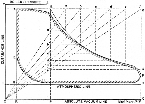
One of the first steps in the design of a steam engine is the construction of an ideal diagram, and the engine is planned to produce this as nearly as possible when in operation. First assume the initial pressure, the ratio of expansion, and the percentage of clearance, for the type of engine under consideration. Draw lines OX and OY at right angles as in Fig. 7. Make OR the same percentage of the stroke that the clearance is of the piston displacement; make RX equal to the length of the stroke (on a reduced scale). Erect the perpendicular RA of such a height that it shall represent, to scale, an absolute pressure per square inch equal to 0.95 of the boiler pressure. Draw in the dotted lines AK and KX, and the atmospheric line LH at a height above OX to represent 14.7 pounds per square inch. Locate the point of cut-off, B, according to the assumed ratio of expansion. Points on the expansion curve BC are found as follows: Divide the distance BK into any[11] number of equal spaces, as shown by a, b, c, d, etc., and connect them with the point O. Through the points of intersection with BP, as a´, b´, c´, d´, etc., draw horizontal lines, and through a, b, c, d, etc., draw vertical lines. The intersection of corresponding horizontal and vertical lines will be points on the theoretical expansion line. If the engine is to be non-condensing, the theoretical work, or indicator diagram, as it is called, will be bounded by the lines ABCHG.
One of the first steps in designing a steam engine is creating an ideal diagram, and the engine is designed to produce this as closely as possible during operation. First, assume the initial pressure, the expansion ratio, and the percentage of clearance for the type of engine you're looking at. Draw lines OX and OY at right angles, just like in Fig. 7. Make OR the same percentage of the stroke that the clearance is of the piston displacement; make RX equal to the length of the stroke (on a reduced scale). Erect the perpendicular RA to a height that represents, to scale, an absolute pressure per square inch equal to 0.95 of the boiler pressure. Draw in the dotted lines AK and KX, and the atmospheric line LH at a height above OX to show 14.7 pounds per square inch. Locate the cut-off point, B, according to the assumed expansion ratio. Points on the expansion curve BC are determined as follows: Divide the distance BK into any number of equal spaces, marked as a, b, c, d, etc., and connect them to point O. Through the intersection points with BP, labeled a´, b´, c´, d´, etc., draw horizontal lines, and through a, b, c, d, etc., draw vertical lines. The intersection of matching horizontal and vertical lines will give points on the theoretical expansion line. If the engine is non-condensing, the theoretical work, or indicator diagram, as it is called, will be bordered by the lines ABCHG.
The actual diagram will vary somewhat from the theoretical, as shown by the shaded lines. The admission line between A and B will slant downward slightly, and the point of cut-off will be rounded, owing to the slow closing of the valve. The first half of the expansion line will fall below the theoretical, owing to a drop in pressure caused by cylinder condensation, but the actual line will rise above the theoretical in the latter part of the stroke on account of re-evaporation, due to heat given out by the hot cylinder walls to the low-pressure steam. Instead of the pressure dropping abruptly at C, release takes place just before the end of the stroke, and the diagram is rounded at CF instead of having sharp corners. The back pressure line FD is drawn slightly above the atmospheric line, a distance to represent about 2 pounds per square inch. At D the exhaust valve closes and compression begins, rounding the bottom of the diagram up to E.
The actual diagram will differ somewhat from the theoretical one, as indicated by the shaded lines. The admission line between A and B will slightly slope downward, and the cut-off point will be rounded because the valve closes slowly. The first half of the expansion line will be below the theoretical due to a drop in pressure caused by cylinder condensation, but the actual line will rise above the theoretical in the latter part of the stroke due to re-evaporation from heat released by the hot cylinder walls to the low-pressure steam. Instead of the pressure dropping sharply at C, the release happens just before the end of the stroke, making the diagram rounded at CF instead of having sharp corners. The back pressure line FD is slightly above the atmospheric line, representing about 2 pounds per square inch. At D, the exhaust valve closes, and compression starts, rounding the bottom of the diagram up to E.
The area of the actual diagram, as shown by the shaded lines in Fig. 7, will be smaller than the theoretical, in about the following ratio:
The area of the actual diagram, as shown by the shaded lines in Fig. 7, will be smaller than the theoretical one, at roughly the following ratio:
Large medium-speed engines, 0.90 of theoretical area.
Small medium-speed engines, 0.85 of theoretical area.
High-speed engines, 0.75 of theoretical area.
Large medium-speed engines, 0.90 of theoretical area.
Small medium-speed engines, 0.85 of theoretical area.
High-speed engines, 0.75 of theoretical area.
CHAPTER II
RATING AND GENERAL PROPORTIONS OF STEAM ENGINES
The capacity or power of a steam engine is rated in horsepower, one horsepower (H. P.) being the equivalent of 33,000 foot-pounds of work done per minute. The horsepower of a given engine may be computed by the formula:
The power of a steam engine is measured in horsepower, with one horsepower (H.P.) equal to 33,000 foot-pounds of work performed per minute. You can calculate the horsepower of a specific engine using the formula:
| APLN | |
| H. P. = | ——— |
| 33,000 |
in which
where
| A | = | area of piston, in square inches, |
| P | = | mean effective pressure per square inch, |
| L | = | length of stroke, in feet, |
| N | = | number of strokes per minute = number of revolutions × 2. |
The derivation of the above formula is easily explained, as follows: The area of the piston, in square inches, multiplied by the mean [12]effective pressure, in pounds per square inch, gives the total force acting on the piston, in pounds. The length of stroke, in feet, times the number of strokes per minute gives the distance the piston moves through, in feet per minute. It has already been shown that the pressure in pounds multiplied by the distance moved through in feet, gives the foot-pounds of work done. Hence, A × P × L × N gives the foot-pounds of work done per minute by a steam engine. If one horsepower is represented by 33,000 foot-pounds per minute, the power or rating of the engine will be obtained by dividing the total foot-pounds of work done per minute by 33,000. For ease in remembering the formula given, it is commonly written
The derivation of the formula above is straightforward, as follows: The area of the piston, in square inches, multiplied by the average effective pressure, in pounds per square inch, gives the total force acting on the piston, in pounds. The stroke length, in feet, multiplied by the number of strokes per minute gives the distance the piston moves, in feet per minute. It has already been shown that the pressure in pounds multiplied by the distance moved in feet results in the foot-pounds of work done. Therefore, A × P × L × N gives the foot-pounds of work done per minute by a steam engine. If one horsepower is defined as 33,000 foot-pounds per minute, the engine's power or rating is calculated by dividing the total foot-pounds of work done per minute by 33,000. For ease of remembering the formula provided, it is typically written
| PLAN | |
| H. P. = | ——— |
| 33,000 |
in which the symbols in the numerator of the second member spell the word “Plan.”
in which the symbols in the numerator of the second part spell the word “Plan.”
Example:—Find the horsepower of the following engine, working under the conditions stated below:
Example:—Calculate the horsepower of the following engine, operating under the conditions mentioned below:
- Diameter of cylinder, 12 inches.
- Length of stroke, 18 inches.
- Revolutions per minute, 300.
- Mean effective pressure (M. E. P.), 40 pounds.
In this problem, then, A = 113 square inches; P = 40 pounds; L = 1.5 feet; and N = 600 strokes.
In this problem, then, A = 113 square inches; P = 40 pounds; L = 1.5 feet; and N = 600 strokes.
Substituting in the formula,
Plugging in the formula,
| 40 × 1.5 × 113 × 600 | ||
| H. P. = | ————————— | = 123. |
| 33,000 |
The mean effective pressure may be found, approximately, for different conditions by means of the factors in the following table of ratios, covering ordinary practice. The rule used is as follows: Multiply the absolute initial pressure by the factor corresponding to the clearance and cut-off as found from Table II, and subtract the absolute back pressure from the result, assuming this to be 17 pounds for non-condensing engines, and 3 pounds for condensing.
The mean effective pressure can be roughly determined for various conditions using the factors in the following table of ratios, which reflect common practice. The method is as follows: Multiply the absolute initial pressure by the factor that matches the clearance and cut-off as indicated in Table II, and then subtract the absolute back pressure from that result, assuming it's 17 pounds for non-condensing engines and 3 pounds for condensing.
Example 1:—A non-condensing engine having 3 per cent clearance, cuts off at 1⁄3 stroke; the initial pressure is 90 pounds gage. What is the M. E. P.?
Example 1:—A non-condensing engine with 3 percent clearance cuts off at 1⁄3 stroke; the initial pressure is 90 pounds gauge. What is the M.E.P.?
The absolute initial pressure is 90 + 15 = 105 pounds. The factor for 3 per cent clearance and 1⁄3 cut-off, from Table II, is 0.71. Applying the rule we have: (105 × 0.71) - 17 = 57.5 pounds per square inch.
The absolute initial pressure is 90 + 15 = 105 pounds. The factor for 3 percent clearance and 1⁄3 cut-off, from Table II, is 0.71. Applying the rule we have: (105 × 0.71) - 17 = 57.5 pounds per square inch.
Example 2:—A condensing engine has a clearance of 5 per cent. It is supplied with steam at 140 pounds gage pressure, and has a ratio of expansion of 6. What is the M. E. P.?
Example 2:—A condensing engine has a clearance of 5 percent. It gets steam at 140 pounds gauge pressure and has an expansion ratio of 6. What is the M. E. P.?
The absolute initial pressure is 140 + 15 = 155. The factor for a ratio of expansion of 6 (1⁄6 cut-off) and 5 per cent clearance is 0.5, which gives (155 × 0.5) - 3 = 74.5 pounds per square inch.
The absolute initial pressure is 140 + 15 = 155. The factor for an expansion ratio of 6 (1⁄6 cut-off) and 5 percent clearance is 0.5, which results in (155 × 0.5) - 3 = 74.5 pounds per square inch.
The power of an engine computed by the method just explained is[13] called the indicated horsepower (I. H. P.), and gives the total power developed, including that required to overcome the friction of the engine itself. The delivered or brake horsepower (B. H. P.) is that delivered by the engine after deducting from the indicated horsepower the power required to operate the moving parts. The brake horsepower commonly varies from 80 to 90 per cent of the indicated horsepower at full load, depending upon the type and size of engine.
The power of an engine calculated using the method just described is[13] known as the indicated horsepower (I.H.P.), which reflects the total power produced, including what’s needed to overcome the engine's own friction. The delivered or brake horsepower (B.H.P.) refers to the power the engine provides after subtracting the energy needed to run the moving parts. The brake horsepower typically ranges from 80 to 90 percent of the indicated horsepower at full load, depending on the engine's type and size.
In proportioning an engine cylinder for any given horsepower, the designer usually has the following data, either given or assumed, for the special type of engine under consideration: Initial pressure, back pressure, clearance, cut-off, and piston speed.
In sizing an engine cylinder for a specific horsepower, the designer typically has the following information, either provided or assumed, for the particular type of engine being considered: initial pressure, back pressure, clearance, cut-off, and piston speed.
These quantities vary in different types of engines, but in the absence of more specific data the values in Table III will be found useful. The back pressure may be taken as 17 pounds per square inch, absolute, for non-condensing engines, and as 3 pounds for condensing engines as previously stated.
These amounts differ between various types of engines, but without more specific data, the values in Table III will be helpful. The back pressure can be considered 17 pounds per square inch, absolute, for non-condensing engines, and 3 pounds for condensing engines, as mentioned earlier.
The first step in proportioning the cylinder is to compute the approximate mean effective pressure from the assumed initial pressure, clearance, and cut-off, by the method already explained. Next assume the piston speed for the type of engine to be designed, and determine the piston area by the following formula:
The first step in sizing the cylinder is to calculate the approximate mean effective pressure from the assumed initial pressure, clearance, and cut-off, using the method already described. Next, assume the piston speed for the type of engine being designed, and determine the piston area using the following formula:
| 33,000 H. P. | |
| A = | ——————————. |
| M. E. P. × piston speed |
This formula usually gives the diameter of the piston in inches and fractions of an inch, while it is desirable to make this dimension an even number of inches. This may be done by taking as the diameter the nearest whole number, and changing the piston speed to correspond. This is done by the use of the following equation.
This formula typically provides the diameter of the piston in inches and fractions of an inch, but it's preferable to round this dimension to an even number of inches. This can be achieved by using the nearest whole number as the diameter and adjusting the piston speed accordingly. This adjustment is made using the following equation.
| First piston speed × first piston area | |
| —————————————— | = new piston speed. |
| new piston area |
In calculating the effective piston area, the area of the piston rod upon one side must be allowed for. The effective or average piston area will then be (2A - a)⁄2, in which A = area of piston, a = area of piston rod. This latter area must be assumed. After assuming a new piston [14]diameter of even inches, its effective or average area must be used in determining the new piston speed. The length of stroke is commonly proportioned to the diameter of cylinder, and the piston speed divided by this will give the number of strokes per minute.
In calculating the effective piston area, you need to take into account the area of the piston rod on one side. The effective or average piston area will then be (2A - a)⁄2, where A is the area of the piston and a is the area of the piston rod. You have to estimate this latter area. After estimating a new piston [14] diameter in whole inches, its effective or average area should be applied to calculate the new piston speed. Usually, the stroke length is proportional to the cylinder diameter, and dividing the piston speed by this length will give you the number of strokes per minute.
Example:—Find the diameter of cylinder, length of stroke, and revolutions per minute for a simple high-speed non-condensing engine of 200 I. H. P., with the following assumptions: Initial pressure, 90 pounds gage; clearance, 7 per cent; cut-off, 1⁄4; piston speed, 700 feet per minute; length of stroke, 1.5 times cylinder diameter.
Example:—Find the diameter of the cylinder, the length of the stroke, and the revolutions per minute for a simple high-speed non-condensing engine of 200 I.H.P., using these assumptions: Initial pressure, 90 pounds gauge; clearance, 7 percent; cut-off, 1⁄4; piston speed, 700 feet per minute; length of stroke, 1.5 times the cylinder diameter.
By using the rules and formulas in the foregoing, we have:
By using the rules and formulas mentioned above, we have:
M. E. P. = (90 + 15) × 0.63 - 17 = 49 pounds.
M. E. P. = (90 + 15) × 0.63 - 17 = 49 pounds.
| 33,000 × 200 | ||
| A = | —————— | = 192.4 square inches. |
| 49 × 700 |
The nearest piston diameter of even inches is 16, which corresponds to an area of 201 square inches. Assume a piston rod diameter of 21⁄2 inches, corresponding to an area of 4.9 square inches, from which the average or effective piston area is found to be (2 × 201) - 4.9⁄2 = 198.5 square inches.
The closest piston diameter that's a whole number is 16 inches, which has an area of 201 square inches. Let's assume the piston rod diameter is 21⁄2 inches, giving it an area of 4.9 square inches. From this, the average or effective piston area is calculated as (2 × 201) - 4.9⁄2 = 198.5 square inches.
Determining now the new piston speed, we have:
Determining the new piston speed now, we have:
| 700 × 192.4 | |
| ————— | = 678.5 feet per minute. |
| 198.5 |
Assuming the length of stroke to be 1.5 times the diameter of the cylinder, it will be 24 inches, or 2 feet.
Assuming the stroke length is 1.5 times the cylinder diameter, it will be 24 inches, or 2 feet.
This will call for 678.5 ÷ 2 = 340 strokes per minute, approximately, or 340 ÷ 2 = 170 revolutions per minute.
This requires 678.5 ÷ 2 = 340 strokes per minute, roughly, or 340 ÷ 2 = 170 revolutions per minute.
CHAPTER III
STEAM ENGINE DETAILS
Some of the most important details of a steam engine are those of its valve gear. The simplest form of valve is that known as the plain slide valve, and as nearly all others are a modification of this, it is essential that the designer should first familiarize himself with this particular type of valve in all its details of operation. After this has been done, a study of other forms of valves will be found a comparatively easy matter. The so called Corliss valve differs radically from the slide valve, but the results to be obtained and the terms used in its design are practically the same. The valve gear of a steam engine is made up of the valve or valves which admit steam to and exhaust it from the cylinder, and of the mechanism which governs the valve movements, the latter usually consisting of one or more eccentrics attached to the main shaft.
Some of the key details of a steam engine are related to its valve gear. The simplest type of valve is known as the plain slide valve, and since almost all other types are variations of this, it’s crucial for the designer to first understand this specific valve and how it operates in detail. Once that’s done, studying other types of valves will be much easier. The so-called Corliss valve is quite different from the slide valve, but the outcomes and terminology used in its design are essentially the same. The valve gear of a steam engine consists of the valve or valves that control steam entering and exiting the cylinder, along with the mechanism that regulates the valve movements, which typically involves one or more eccentrics connected to the main shaft.
The Slide Valve
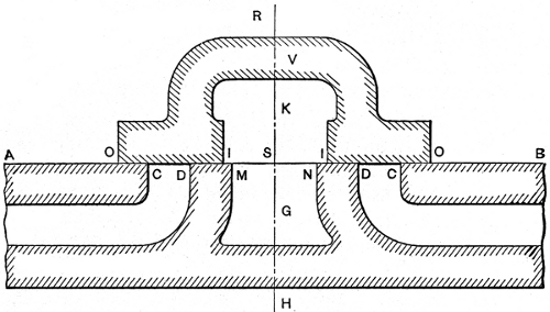
Fig. 8. Longitudinal Section of Slide Valve with Ports
Fig. 8. Longitudinal Section of Slide Valve with Ports
Fig. 8 shows a longitudinal section of a slide valve with the ports, bridges, etc. The valve is shown in mid-position in order that certain points relating to it may be more easily understood. The valve, V, consists of a hollow casting, with ends projecting beyond the ports as shown; the lower face is smoothly finished and fitted to the valve seat AB. In operation it slides back and forth, opening and closing the ports which connect the steam chest with the cylinder. Steam is admitted to the cylinder when either port CD or DC is opened, and is released when the ports are brought into communication with the exhaust port MN. This is accomplished by the movement of the valve, which brings one of the cylinder ports and the exhaust port both under the hollow arch K. The portions DM and ND of the valve seat are called the bridges.
Fig. 8 shows a side view of a slide valve with the ports, bridges, etc. The valve is positioned in the middle so that certain aspects can be more easily understood. The valve, V, is made of a hollow casting, with ends extending beyond the ports as shown; the lower face is smooth and fits the valve seat AB. During operation, it moves back and forth, opening and closing the ports that connect the steam chest with the cylinder. Steam enters the cylinder when either port CD or DC is opened, and is released when the ports connect with the exhaust port MN. This is done by the movement of the valve, which aligns one of the cylinder ports with the exhaust port under the hollow arch K. The parts DM and ND of the valve seat are referred to as the bridges.
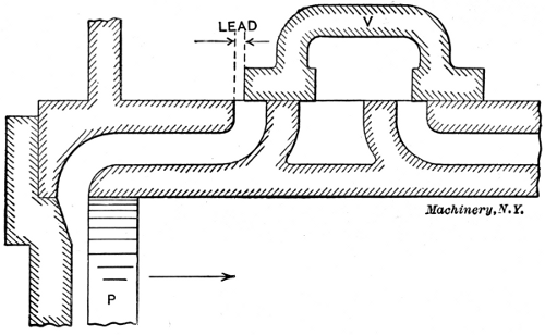
[16]It will be seen by reference to Fig. 8 that the portions OI and IO are wider than the ports which they cover. This extra width is called the lap, OC being the outside lap and DI the inside or exhaust lap. The object of outside lap is that the steam may be shut off after the piston has moved forward a certain distance, and be expanded during the remainder of the stroke. If there were no outside lap, steam would be admitted throughout the entire stroke and there would be no expansion. If there were no inside lap, exhaust would take place throughout the whole stroke, and the advantages of premature release and compression would be lost. Hence, outside lap affects the cut-off, and inside lap affects release and compression. A valve has lead when it begins to uncover the steam port before the end of the return stroke of the piston. This is shown in Fig. 9, where the piston P is just ready to start on its forward stroke as indicated by the arrow. The valve has already opened a distance equal to the lead, and the steam has had an opportunity to enter and fill the clearance space before the beginning of the stroke. The lead varies in different engines, being greater in high-speed than in low-speed types.
[16]It will be seen by reference to Fig. 8 that the sections OI and IO are broader than the ports they cover. This extra width is known as the lap, with OC as the outer lap and DI as the inner or exhaust lap. The purpose of the outer lap is to allow the steam to be shut off after the piston has moved forward a certain distance, and to enable it to expand during the rest of the stroke. Without the outer lap, steam would be let in for the entire stroke, resulting in no expansion. If there were no inner lap, exhaust would occur throughout the entire stroke, losing the benefits of premature release and compression. Thus, the outer lap influences the cut-off, while the inner lap affects release and compression. A valve has lead when it starts to uncover the steam port before the piston's return stroke is finished. This is illustrated in Fig. 9, where the piston P is just about to begin its forward stroke, as indicated by the arrow. The valve has already opened a distance equal to the lead, letting steam enter and fill the clearance space before the stroke starts. The lead varies in different engines, being greater in high-speed engines compared to low-speed ones.
The Eccentric
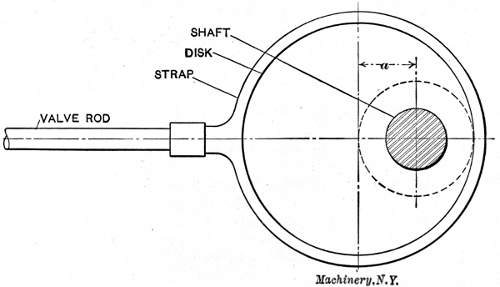
The slide valve is usually driven by an eccentric attached to the main shaft. A diagram of an eccentric is shown in Fig. 10. An eccentric is, in reality, a short crank with a crank-pin of such size that it surrounds the shaft. The arm of a crank is the distance between the center of the shaft, and the center of the crank-pin. The throw of an eccentric corresponds to this, and is the distance between the center of the shaft and the center of the eccentric disk, as shown at a in Fig. 10. The disk is keyed to the shaft, and as the shaft revolves, the center of the disk rotates about it as shown by the dotted line, and gives a forward and backward movement to the valve rod equal to twice the throw a.
The slide valve is usually operated by an eccentric attached to the main shaft. A diagram of an eccentric is shown in Fig. 10. An eccentric is basically a short crank with a crank-pin that fits around the shaft. The arm of the crank is the distance between the center of the shaft and the center of the crank-pin. The throw of an eccentric is the same as this and is the distance from the center of the shaft to the center of the eccentric disk, as indicated at a in Fig. 10. The disk is attached to the shaft, and as the shaft rotates, the center of the disk moves around it as shown by the dotted line, providing a forward and backward motion to the valve rod that is twice the throw a.
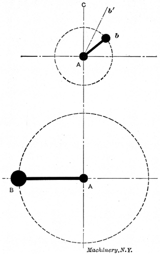
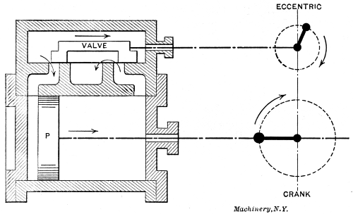
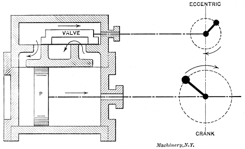
In Fig. 11 let A represent the center of the main shaft, B the crank-pin to which the connecting-rod is attached (see H, 1), and the dotted circle through B the path of the crank-pin around the shaft. For simplicity, let the eccentric be represented in a similar manner by the crank Ab, and its path by the dotted circle through b. Fig. 12 shows a similar diagram with the piston P and the valve in the positions corresponding to the positions of the crank and eccentric in Fig. 11, and in the diagram at the right in Fig. 12. The piston is at the extreme left, ready to start on its forward stroke toward the right. The crank-pin B is at its extreme inner position. When the valve is at its mid-position, as in Fig. 8, the eccentric arm Ab will coincide with the line AC, Fig. 11. If the eccentric is turned on the shaft sufficiently to bring the left-hand edge O, Fig. 8, of the valve in line with the edge C of the port, the arm of the eccentric will have moved from its vertical position to that shown by the line Ab´ in Fig. 11. The angle through which the eccentric has been turned from the vertical to bring about this result is called the angular advance, and is shown by angle CAb´ in Fig. 11. The angular advance evidently depends upon the amount of lap.
In Fig. 11, let A be the center of the main shaft, B the crank-pin attached to the connecting-rod (see H, 1), and the dotted circle through B represents the path of the crank-pin around the shaft. For simplicity, let the eccentric be represented similarly by the crank Ab, and its path by the dotted circle through b. Fig. 12 shows a similar diagram with the piston P and the valve in positions that correspond to the crank and eccentric in Fig. 11, and in the diagram on the right in Fig. 12. The piston is at the far left, ready to begin its forward stroke to the right. The crank-pin B is at its furthest inner position. When the valve is at its mid-position, as in Fig. 8, the eccentric arm Ab will line up with the line AC, Fig. 11. If the eccentric is rotated on the shaft enough to align the left edge O, Fig. 8, of the valve with the edge C of the port, the arm of the eccentric will have moved from its vertical position to the position shown by the line Ab´ in Fig. 11. The angle through which the eccentric has been rotated from vertical to achieve this is called the angular advance, represented by angle CAb´ in Fig. 11. The angular advance clearly depends on the amount of lap.
If the valve is to be given a lead, as indicated in Fig. 12, the eccentric must be turned still further on the shaft to open the valve slightly before the piston starts on its forward movement. This brings the eccentric to the position Ab shown in Fig. 11. The angle through which the eccentric is turned to give the necessary lead opening to the[18] valve is called the angle of lead, and is shown by angle b´Ab. By reference to Fig. 11, it is seen that the total angle between the crank and the eccentric is 90 degrees, plus the angular advance, plus the angle of lead. This is the total angle of advance.
If the valve is supposed to have a lead, as mentioned in Fig. 12, the eccentric must be rotated even further on the shaft to slightly open the valve before the piston begins its forward motion. This positions the eccentric at Ab as shown in Fig. 11. The angle by which the eccentric is turned to provide the necessary lead opening to the [18] valve is called the angle of lead, represented by angle b´Ab. Referring to Fig. 11, it can be seen that the total angle between the crank and the eccentric is 90 degrees, plus the angular advance, plus the angle of lead. This forms the total angle of advance.
The relative positions of the piston and valve at different periods of the stroke are illustrated in Figs. 12 to 16. Fig. 12 shows the piston just beginning the forward stroke, the valve having uncovered the admission port an amount equal to the lead. The crank is in a horizontal position, and the eccentric has moved from the vertical an amount sufficient to move the valve toward the right a distance equal to the outside lap plus the lead. The arrows show that steam is entering the left-hand port and is being exhausted through the right-hand port.
The positions of the piston and valve at different points in the stroke are shown in Figs. 12 to 16. Fig. 12 depicts the piston just starting the forward stroke, with the valve having opened the admission port by the same amount as the lead. The crank is horizontal, and the eccentric has moved away from the vertical enough to push the valve to the right by a distance equal to the outside lap plus the lead. The arrows indicate that steam is entering the left port and is being released through the right port.
 |
 |
| Fig. 12. Piston just beginning Forward Stroke | Fig. 13. Steam Port fully Opened |
 |
 |
| Fig. 14. Valve has started on Backward Stroke | Fig. 15. Both Steam Ports Closed |
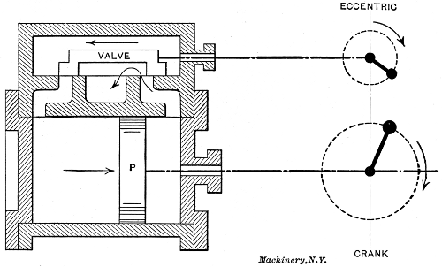
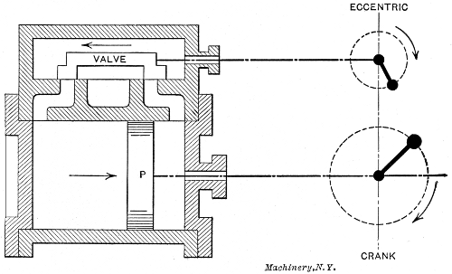
[19]In Fig. 13 it is seen that the valve has traveled forward sufficiently to open the steam port to its fullest extent, and the piston has moved to the point indicated. The exhaust port is still wide open, and the relative positions of the crank and eccentric are shown in the diagram at the right. In Fig. 14 the eccentric has passed the horizontal position and the valve has started on its backward stroke, while the piston is still moving forward. The admission port is closed, cut-off having taken place, and the steam is expanding. The exhaust port is still partially open.
[19]In Fig. 13 you can see that the valve has moved forward enough to fully open the steam port, and the piston has reached the indicated point. The exhaust port remains wide open, and the diagram on the right shows the positions of the crank and eccentric. In Fig. 14 the eccentric has gone past the horizontal position, and the valve has begun its backward movement, while the piston is still moving forward. The admission port is closed, with the cut-off occurring, and the steam is expanding. The exhaust port is still partially open.
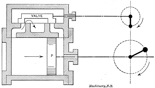
In Fig. 15 both ports are closed and compression is taking place in front of the piston while expansion continues back of it. Release occurs in Fig. 16 just before the piston reaches the end of its stroke. The eccentric crank is now in a vertical position, pointing downward, and exhaust is just beginning to take place through the left-hand port.[20] This completes the different stages of a single stroke, the same features being repeated upon the return of the piston to its original position. The conditions of lap, lead, angular advance, etc., pertain to practically all valves, whatever their design.
In Fig. 15, both ports are closed, and compression is happening in front of the piston while expansion continues behind it. Release occurs in Fig. 16 just before the piston reaches the end of its stroke. The eccentric crank is now in a vertical position, pointing down, and exhaust is just starting to happen through the left-hand port.[20] This wraps up the different stages of a single stroke, with the same features repeating when the piston returns to its original position. The conditions of lap, lead, angular advance, etc., apply to almost all valves, regardless of their design.
Different Types of Valves
In the following are shown some of the valves in common use, being, with the exception of the Corliss, modifications of the plain slide valve, and similar in their action.
In the following, some of the commonly used valves are displayed, with the exception of the Corliss, which are all variations of the plain slide valve and similar in their operation.
Double-Ported Balanced Valve.—A valve of this type has already been shown in Fig. 2. This valve is flat in form, with two finished surfaces,[21] and works between the valve-seat and a plate, the latter being prevented from pressing against the valve by special bearing surfaces which hold it about 0.002 inch away. The construction of the valve is such that when open the steam reaches the port through two openings as indicated by the arrows at the left. The object of this is to reduce the motion of the valve and quicken its action in admitting and cutting off steam.
Double-Ported Balanced Valve.—A valve like this has already been shown in Fig. 2. This valve has a flat design, with two smooth surfaces,[21] and it operates between the valve seat and a plate, which is kept about 0.002 inches away from the valve by special bearing surfaces. The design of the valve allows steam to reach the port through two openings, as indicated by the arrows on the left. The purpose of this is to minimize the movement of the valve and speed up its action in allowing and stopping steam.
Piston Valve.—The piston valve shown in Fig. 17 is identical in its action with the plain slide valve shown in Fig. 8, except that it is circular in section instead of being flat or rectangular. The advantage claimed for this type of valve is the greater ease in fitting cylindrical surfaces as compared with flat ones. The valve slides in special[22] bushings which may be renewed when worn. Piston valves are also made with double ports.
Piston Valve.—The piston valve shown in Fig. 17 works the same way as the plain slide valve shown in Fig. 8, except that it has a circular shape instead of being flat or rectangular. The advantage of this type of valve is that it's easier to fit cylindrical surfaces compared to flat ones. The valve slides in special[22] bushings that can be replaced when they wear out. Piston valves can also be made with double ports.
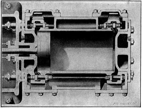
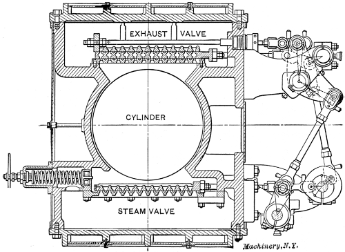
Fig. 18. Section through Cylinder of Engine of the Four-valve Type
Fig. 18. Cross-section of the Engine Cylinder of the Four-valve Type
Four-Valve Type.—Fig. 18 shows a horizontal section through the cylinder and valves of an engine of the four-valve type. The admission valves are shown at the top of the illustration and the exhaust valves at the bottom, although, in reality, they are at the sides of the cylinder. The advantage of an arrangement of this kind is that the valves may be set independently of each other and the work done by the two ends[23] of the cylinder equalized. The various events, such as cut-off, compression, etc., may be adjusted without regard to each other, and in such a manner as to give the best results, a condition which is not possible with a single valve.
Four-Valve Type.—Fig. 18 shows a horizontal section through the cylinder and valves of a four-valve engine. The intake valves are at the top of the illustration, while the exhaust valves are at the bottom; however, in reality, they are on the sides of the cylinder. The benefit of this setup is that the valves can be adjusted independently, allowing the work done by both ends of the cylinder to be balanced. Various processes, like cut-off and compression, can be fine-tuned separately to achieve optimal results, which isn’t possible with a single valve.
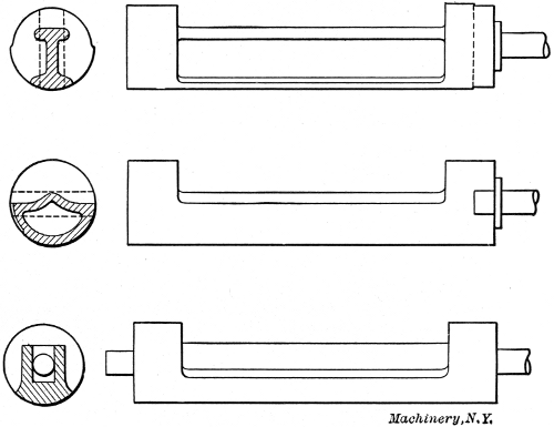
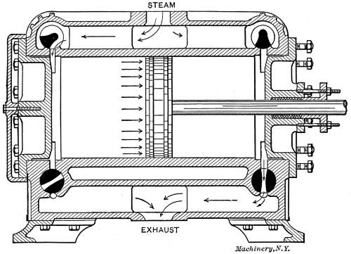
Fig. 20. Longitudinal Section through Corliss Engine
Fig. 20. Longitudinal Section through Corliss Engine
Gridiron Valve.—One of the principal objects sought in the design of a valve is quick action at the points of admission and cut-off. This requires the uncovering of a large port opening with a comparatively small travel of the valve. The gridiron valve shown in Fig. 21 is constructed especially for this purpose. This valve is of the four-valve type, one steam valve and one exhaust valve being shown in the section. Both the valve and its seat contain a number of narrow openings or ports, so that a short movement of the valve will open or close a comparatively large opening. For example, the steam valve in the illustration has 12 openings, so that if they are 1⁄4 inch in width each, a movement of 1⁄4 inch of the valve will open a space 12 × 1⁄4 = 3 inches in length.
Gridiron Valve.—One of the main goals in designing a valve is to ensure quick action when opening and closing. This requires a large port to be exposed with a relatively short valve movement. The gridiron valve shown in Fig. 21 is specifically made for this purpose. It features a four-valve setup, with one steam valve and one exhaust valve visible in the section. Both the valve and its seat have several narrow openings or ports, allowing a small movement of the valve to create a much larger opening. For instance, the steam valve in the illustration has 12 openings, so if each one is 1⁄4 inch wide, moving the valve 1⁄4 inch will open an area 12 × 1⁄4 = 3 inches in length.
Corliss Valve.—A section through an engine cylinder equipped with Corliss valves is shown in Fig. 20. There are four cylindrical valves in this type of engine, two steam valves at the top and two exhaust valves at the bottom. This arrangement is used to secure proper drainage. The action of the admission and exhaust valves is indicated by the arrows, the upper left-hand and the lower right-hand valve being open and the other two closed.[24]
Corliss Valve.—A cross-section of an engine cylinder with Corliss valves is shown in Fig. 20. This type of engine has four cylindrical valves: two steam valves at the top and two exhaust valves at the bottom. This setup ensures proper drainage. The movement of the admission and exhaust valves is indicated by the arrows, with the upper left-hand and lower right-hand valves being open and the other two closed.[24]
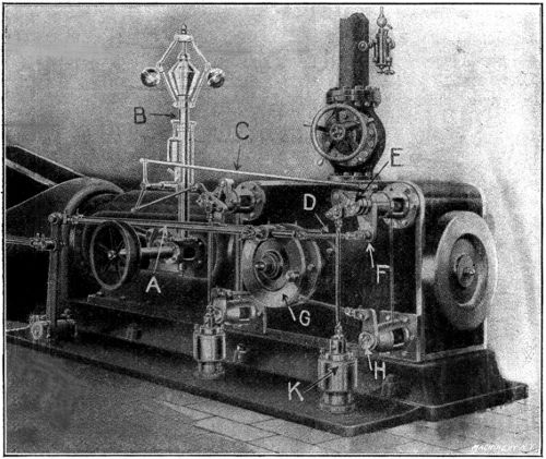
Fig. 22. The Monarch Engine with Corliss Valve Gear.—A, Rod to Eccentric; B, Governor;
C, Reach Rod; D, Radial Arm; E, Steam Valve; F, Bell-crank; G, Wrist Plate;
H, Exhaust Valve; K, Dash-pot
Fig. 22. The Monarch Engine with Corliss Valve Gear.—A, Rod to Eccentric; B, Governor;
C, Reach Rod; D, Radial Arm; E, Steam Valve; F, Bell-crank; G, Wrist Plate;
H, Exhaust Valve; K, Dash-pot
Side and sectional views of different forms of this type of valve are shown in Fig. 19. They are operated by means of short crank-arms which are attached to a wrist-plate by means of radial arms or rods, as shown in Fig. 22. The wrist-plate, in turn, is given a partial backward and forward rotation by means of an eccentric attached to the main shaft and connected to the upper part of the wrist-plate by a rod as indicated. The exhaust valves are both opened and closed by the action of the wrist-plate and connecting rods. The steam valves are opened in this manner, but are closed by the suction of dash pots attached to the drop levers on the valve stems by means of vertical rods, as shown.
Side and sectional views of different types of this valve are shown in Fig. 19. They are operated with short crank arms connected to a wrist plate through radial arms or rods, as illustrated in Fig. 22. The wrist plate is rotated partially back and forth by an eccentric attached to the main shaft, which connects to the upper part of the wrist plate with a rod, as indicated. The exhaust valves open and close due to the movement of the wrist plate and connecting rods. The steam valves open this way but close by the suction from dash pots linked to the drop levers on the valve stems via vertical rods, as shown.
 |
 |
| Fig. 23 | Fig. 24 |
 |
 |
| Fig. 25 | Fig. 26 |
Figs. 23 to 26. Action of Corliss Valve Gear
Figs. 23 to 26. Function of Corliss Valve Gear
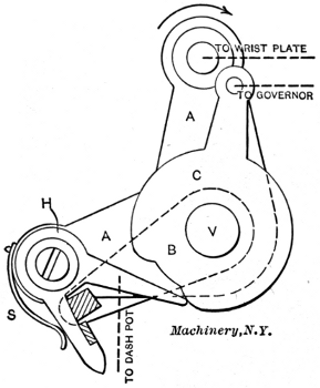
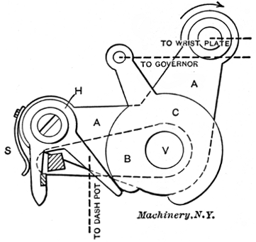
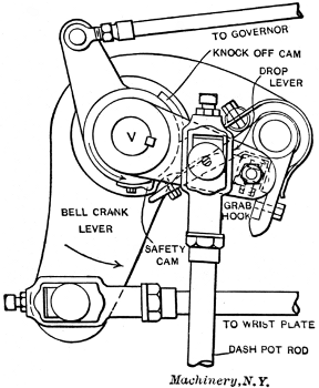
The action of the steam or admission valves is best explained by reference to Figs. 23 to 26. Referring to Fig. 23, A is a bell-crank which turns loosely upon the valve stem V. The lower left-hand extension of A carries the grab hook H, while the upper extension is connected with the wrist-plate as indicated. Ordinarily the hook H is pressed[25] inward by the spring S, so that the longer arm of the hook is always pressed against the knock-off cam C. The cam C also turns upon the valve stem V and is connected with the governor by means of a reach rod as indicated in Fig. 23 and shown in Fig. 22. The drop lever B is keyed to the valve stem V, and is connected with the dash pot by a rod as indicated by the dotted line. This is also shown in Fig. 22. The end of the drop lever carries a steel block (shown shaded in Fig. 23), which engages with the grab hook H.
The function of the steam or admission valves is best explained by referring to Figs. 23 to 26. In Fig. 23, A is a bell-crank that turns loosely on the valve stem V. The lower left side of A has the grab hook H, while the upper part is connected to the wrist-plate as shown. Normally, the hook H is pushed inward by the spring S, so that the longer arm of the hook is always pressed against the knock-off cam C. The cam C also turns on the valve stem V and is connected to the governor through a reach rod as indicated in Fig. 23 and illustrated in Fig. 22. The drop lever B is secured to the valve stem V and is linked to the dash pot by a rod as shown by the dotted line. This is also displayed in Fig. 22. The end of the drop lever holds a steel block (shown shaded in Fig. 23), which interacts with the grab hook H.
When in operation, the bell-crank is rotated in the direction of the arrow by the action of the wrist-plate and connecting-rod. As the bell-crank rotates, the grab hook engages the steel block at the end of the drop lever B and lifts it, thus causing the valve to open, and to remain so until the bell-crank has advanced so far that the longer arm of the grab hook H is pressed outward by the projection on the knock-off cam, as shown in Fig. 24. The drop lever now being released, the valve is quickly closed by the suction of the dash pot, which pulls the lever down to its original position by means of the rod previously mentioned.
When in operation, the bell-crank is rotated in the direction of the arrow by the movement of the wrist-plate and connecting-rod. As the bell-crank turns, the grab hook engages the steel block at the end of the drop lever B and lifts it, causing the valve to open and stay open until the bell-crank has moved far enough that the longer arm of the grab hook H is pushed outward by the projection on the knock-off cam, as shown in Fig. 24. With the drop lever now released, the valve quickly closes due to the suction of the dash pot, which pulls the lever back down to its original position through the previously mentioned rod.
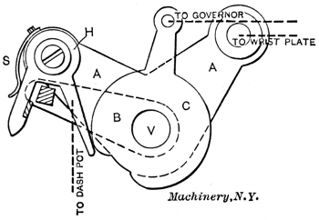
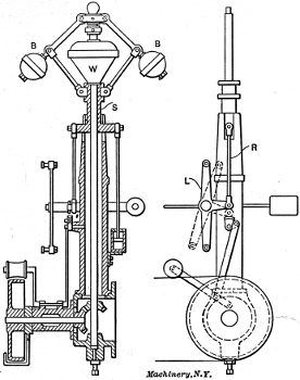
The governor operates by changing the point of cut-off through the action of the cam C. With the cam in the position shown in Fig. 25, cut-off occurs earlier than in Fig. 24. Should the cam be turned in the opposite direction (clockwise), cut-off would take place later. A detailed view of the complete valve mechanism described is shown assembled in Fig. 26, with each part properly named. A detail of the governor is shown in Fig. 27. An increase in speed causes the revolving balls BB to swing outward, thus raising the weight W and the sleeve S. This in turn operates the lever L through rod R and a bell-crank attachment, as shown in the right-hand view. An upward and downward movement of the balls, due to a change in speed of the engine, swings the lever L backward and forward as shown by the[26] full and dotted lines. The ends of this lever are attached by means of reach-rods to the knock-off cams, this being shown more clearly in Fig. 22. The connections between the lever L and cam C are such that a raising of the balls, due to increased speed, will reduce the cut-off and thus slow down the engine. On the other hand, a falling of the balls will lengthen the cut-off through the same mechanism.
The governor works by adjusting the cut-off point through the cam C. With the cam in the position shown in Fig. 25, the cut-off occurs earlier than in Fig. 24. If the cam is turned the other way (clockwise), the cut-off will happen later. A detailed view of the complete valve mechanism is shown assembled in Fig. 26, with each part properly labeled. A closer look at the governor can be seen in Fig. 27. When speed increases, the revolving balls BB swing outward, which raises the weight W and the sleeve S. This movement operates the lever L through rod R and a bell-crank attachment, as shown in the right-hand view. The upward and downward movement of the balls, caused by a change in the engine's speed, causes the lever L to swing back and forth, as indicated by the[26] solid and dotted lines. The ends of this lever are connected by reach-rods to the knock-off cams, as shown more clearly in Fig. 22. The connections between the lever L and cam C are designed so that when the balls rise due to increased speed, the cut-off is reduced, slowing down the engine. Conversely, when the balls drop, the cut-off is lengthened through the same mechanism.
Mention has already been made of the dash pot which is used to close the valve suddenly after being released from the grab hook. The dash-pot rod is shown in Fig. 26, and indicated by dotted lines in Figs. 23 to 25. A detailed view of one form of dash pot is shown in Fig. 28. When the valve is opened, the rod attached to lever B, Figs. 23 and 24, raises the piston P, Fig. 28, and a partial vacuum is formed beneath it which draws the piston and connecting rod down by suction as soon as the lever B is released, and thus closes the valve suddenly and [27]without shock. The strength of the suction and the air cushion for this piston are regulated by the inlet and outlet valves shown on the sides of the dash pot.
Mention has already been made of the dash pot that is used to close the valve quickly after being released from the grab hook. The dash-pot rod is shown in Fig. 26, and indicated by dotted lines in Figs. 23 to 25. A detailed view of one type of dash pot is shown in Fig. 28. When the valve is opened, the rod attached to lever B, Figs. 23 and 24, lifts the piston P, Fig. 28, creating a partial vacuum beneath it that pulls the piston and connecting rod down by suction as soon as lever B is released, which then closes the valve quickly and [27] without a jolt. The strength of the suction and the air cushion for this piston are controlled by the inlet and outlet valves located on the sides of the dash pot.
Engine Details
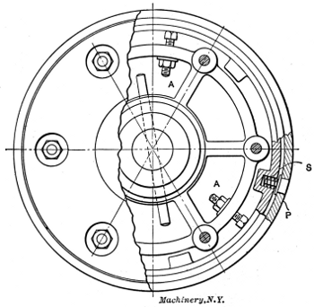 |
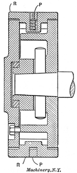 |
| Figs. 29 and 30. Plan and Longitudinal Section of Adjustable Piston | |
A partial cross-section of an adjustable piston is shown in Fig. 29, and a longitudinal section of the same piston in Fig. 30. The principal feature to be emphasized is the method of automatic expansion employed to take up any wear and keep the piston tight. In setting up the piston a hand adjustment is made of the outer sleeve or ring R by means of the set-screws AA. Ring R is made in several sections, so that it may be expanded in the form of a true circle. Further tightness is secured without undue friction by means of the packing ring P which fits in a groove in R and is forced lightly against the walls of the cylinder by a number of coil springs, one of which is shown at S. As the cylinder and piston become worn, screws A are adjusted from time to time, and the fine adjustment for tightness is cared for by the packing ring P and the coil springs S.
A partial cross-section of an adjustable piston is shown in Fig. 29, and a longitudinal section of the same piston in Fig. 30. The main feature to highlight is the automatic expansion method used to accommodate any wear and keep the piston snug. When setting up the piston, you manually adjust the outer sleeve or ring R with the set-screws AA. Ring R is made in several sections so it can be expanded into a true circle. Additional tightness is achieved without excessive friction by using the packing ring P, which fits into a groove in R and is pressed gently against the walls of the cylinder by a series of coil springs, one of which is shown at S. As the cylinder and piston wear down, screws A are adjusted periodically, and the fine adjustment for tightness is managed by the packing ring P and the coil springs S.
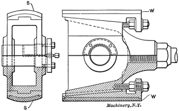
[28]The points to be brought out in connection with the cross-head are the methods of alignment and adjustment. A typical cross-head is shown in cross and longitudinal sections in Fig. 31. Alignment in a straight line, longitudinally, is secured by the cylindrical form of the bearing surfaces or shoes, shown at S. These are sometimes made V-shaped in order to secure the same result. The wear on a cross-head comes on the surfaces S, and is taken up by the use of screw wedges W, shown in the longitudinal section. As the sliding surfaces become worn, the wedges are forced in slightly by screwing in the set-screws and clamping them in place by means of the check-nuts.
[28]The important points to discuss regarding the cross-head are the alignment and adjustment methods. A typical cross-head is depicted in both cross and longitudinal sections in Fig. 31. Straight-line alignment, longitudinally, is achieved through the cylindrical shape of the bearing surfaces or shoes, labeled S. Sometimes, these are made in a V-shape to achieve the same effect. Wear on a cross-head occurs on the surfaces S, which is managed by using screw wedges W, as shown in the longitudinal section. As the sliding surfaces wear down, the wedges can be pushed in slightly by tightening the set-screws and securing them in place with the check-nuts.
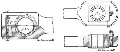
Figs. 32 and 33. Methods Commonly Used for Taking Up Wear in a Connecting-rod
Figs. 32 and 33. Common Methods for Adjusting Wear in a Connecting Rod
The method commonly employed in taking up the wear in a connecting-rod is shown in Figs. 32 and 33. The wear at the wrist-pin is taken by the so called brasses, shown at B in the illustrations. The inner brass, in both cases, fits in a suitable groove, and is held stationary when once in place. The outer brass is adjustable, being forced toward the wrist-pin by a sliding wedge which is operated by one or more set-screws. In Fig. 32 the wedge is held in a vertical position, and is adjusted by two screws as shown. The arrangement made use of in Fig. 33 has the wedge passing through the rod in a horizontal position, and adjusted by means of a single screw, as shown in the[29] lower view. With the arrangements shown, tightening up the brasses shortens the length of the rod. In practice the wedges at each end of the rod are so placed that tightening one shortens the rod, and tightening the other lengthens it, the total effect being to keep the connecting-rod at its original length.
The method commonly used to manage wear in a connecting rod is shown in Figs. 32 and 33. The wear at the wrist pin is addressed by the brasses, shown at B in the illustrations. The inner brass fits into a suitable groove and remains stationary once in place. The outer brass is adjustable, being pushed toward the wrist pin by a sliding wedge operated by one or more set screws. In Fig. 32, the wedge is kept in a vertical position and is adjusted by two screws as shown. The setup in Fig. 33 has the wedge going through the rod in a horizontal position and adjusted by a single screw, as shown in the [29] lower view. With these setups, tightening the brasses shortens the length of the rod. In practice, the wedges at each end of the rod are arranged so that tightening one shortens the rod, while tightening the other lengthens it, keeping the connecting rod at its original length overall.
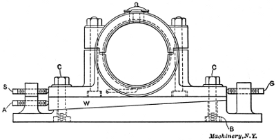 |
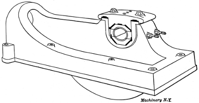 |
|
| Fig. 34. Outboard Bearing for Corliss Type Engine | Fig. 35. Inner Bearing and Bed of Corliss Engine |
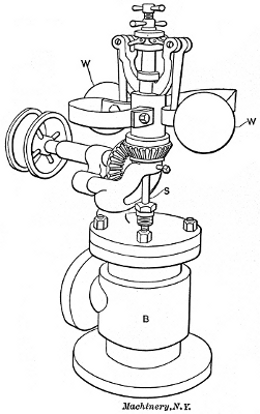
A common form of outboard bearing for an engine of the slow-speed or Corliss type is illustrated in Fig. 34. The various adjustments for alignment and for taking up wear are the important points considered in this case. The plate B is fastened to the stone foundation by anchor bolts not shown. Sidewise movement is secured by loosening the bolts C, which pass through slots in the bearing, and adjusting by means of the screws S. Vertical adjustment is obtained by use of the wedge W, which is forced in by the screw A, as required. The inner bearing and bed piece of a heavy duty Corliss engine is shown in Fig. 35. The bearing in this case is made up of four sections, so arranged that either horizontal or vertical adjustment may be secured by the use of adjusting screws and check-nuts.
A common type of outboard bearing for a slow-speed or Corliss engine is shown in Fig. 34. The key points in this case are the various adjustments for alignment and compensation for wear. The plate B is attached to the stone foundation using anchor bolts that aren't shown. Sideways movement is managed by loosening the bolts C, which go through slots in the bearing, and adjusting with the screws S. For vertical adjustment, a wedge W is used, which is driven in by the screw A as necessary. The inner bearing and bed piece of a heavy-duty Corliss engine is displayed in Fig. 35. In this instance, the bearing consists of four sections, designed so that either horizontal or vertical adjustment can be made using the adjusting screws and check nuts.
Engines of the slide-valve type are usually provided either with a fly-ball throttling governor, or a shaft governor. A common form of throttling governor is shown in Fig. 36. As the speed increases the balls W are thrown outward by the action of the centrifugal force, and being attached to arms hinged above them, any outward movement causes them to rise. This operates the spindle S, which, in turn, partially closes the balanced valve in body B, thus cutting down the steam supply delivered to the engine. The action of a throttling governor upon the work diagram of an engine is shown in Fig. 38. Let the full line represent the form of the diagram with the engine working at full load. Now, if a part of the load be thrown off, the engine will speed up slightly, causing the governor to act as described, thus bringing the admission and expansion lines into the lower positions, as shown in dotted lines.
Engines with slide valves typically come with either a fly-ball throttle governor or a shaft governor. A common type of throttle governor is shown in Fig. 36. As the speed increases, the balls W are pushed outward by centrifugal force, and since they are attached to arms that are hinged above them, any outward movement causes them to rise. This movement operates the spindle S, which partially closes the balanced valve in body B, reducing the steam supply to the engine. The effect of a throttle governor on the work diagram of an engine is illustrated in Fig. 38. The solid line represents the diagram when the engine is running at full load. If part of the load is removed, the engine will speed up slightly, leading the governor to operate as described, which shifts the admission and expansion lines to the lower positions, as indicated by the dotted lines.
The shaft governor is used almost universally on high-speed engines, and is shown in one form in Fig. 37. It consists, in this case, of two weights W, hinged to the spokes of the wheel near the circumference[30] by means of suitable arms. Attached to the arms, as shown, are coil springs C. The ends of the arms beyond the weights are connected by means of levers L to the eccentric disk. When the engine speeds up, the weights tend to swing outward toward the rim of the wheel, the amount of the movement being regulated by the tension of the springs C. As the arms move outward, the levers at the ends turn the eccentric disk on the shaft, the effect of which is to change the angle of advance and shorten the cut-off. When the speed falls below the normal, the weights move toward the center and the cut-off is lengthened. The effect of this form of governor on the diagram is shown in Fig. 39. The full line represents the diagram at full load, and the dotted line when the engine is under-loaded.
The shaft governor is widely used on high-speed engines and is illustrated in one form in Fig. 37. It consists, in this instance, of two weights W, attached to the spokes of the wheel near the edge[30] using suitable arms. Coil springs C are connected to the arms as shown. The ends of the arms beyond the weights are linked through levers L to the eccentric disk. When the engine speeds up, the weights swing outward toward the edge of the wheel, with the movement controlled by the tension of the springs C. As the arms extend outward, the levers at the ends turn the eccentric disk on the shaft, changing the angle of advance and shortening the cut-off. When the speed drops below normal, the weights move toward the center, and the cut-off is lengthened. The impact of this type of governor on the diagram is shown in Fig. 39. The solid line represents the diagram at full load, while the dotted line depicts when the engine is under-loaded.
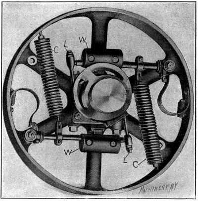
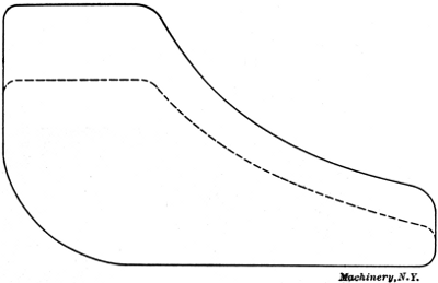
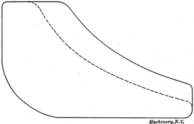
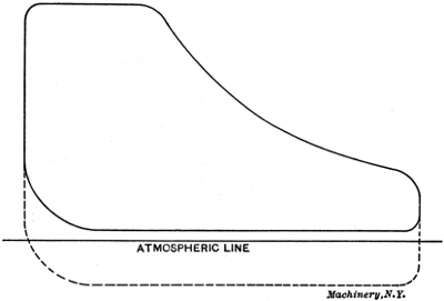
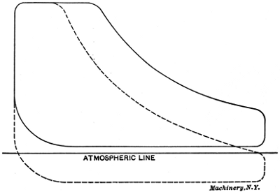
CHAPTER IV
STEAM ENGINE ECONOMY
Under the general heading of steam engine economy, such items as cylinder condensation, steam consumption, efficiency, ratio of expansion, under- and over-loading, condensing, etc., are treated.
Under the general topic of steam engine efficiency, aspects like cylinder condensation, steam usage, efficiency, expansion ratio, under-loading and over-loading, and condensing, etc., are discussed.
The principal waste of steam in the operation of an engine is due to condensation during the first part of the stroke. This condensation is due to the fact that during expansion and exhaust the cylinder walls[31] and head and the piston are in contact with comparatively cool steam, and, therefore, give up a considerable amount of heat. When fresh steam is admitted at a high temperature, it immediately gives up sufficient heat to raise the cylinder walls to a temperature approximating that of the entering steam. This results in the condensation of a certain amount of steam, the quantity depending upon the time allowed for the transfer of heat, the area of exposed surface, and the temperature of the cylinder walls. During the period of expansion the temperature falls rapidly, and the steam being wet, absorbs a large amount of heat. After the exhaust valve opens, the drop in pressure allows the moisture that has collected on the cylinder walls to evaporate into steam, so that during the exhaust period but little heat is transferred. With the admission of fresh steam at boiler pressure, a mist is condensed on the cylinder walls, which greatly increases the rapidity with which heat is absorbed.
The main loss of steam in how an engine operates happens due to condensation during the early part of the stroke. This condensation occurs because, during expansion and exhaust, the cylinder walls[31], cylinder head, and piston come into contact with relatively cool steam, which causes them to lose a significant amount of heat. When fresh steam at a high temperature enters, it quickly transfers enough heat to raise the cylinder walls to a temperature close to that of the incoming steam. This leads to the condensation of some steam, with the amount depending on the time allowed for heat transfer, the surface area exposed, and the temperature of the cylinder walls. During the expansion phase, the temperature drops quickly, and the wet steam absorbs a lot of heat. After the exhaust valve opens, the decrease in pressure allows the moisture on the cylinder walls to turn back into steam, so there isn't much heat transfer during the exhaust phase. When fresh steam at boiler pressure is admitted, it causes a mist to condense on the cylinder walls, which significantly speeds up the heat absorption process.
The amount of heat lost through cylinder condensation is best shown by a practical illustration. One horsepower is equal to 33,000 foot-pounds of work per minute, or 33,000 × 60 = 1,980,000 foot-pounds per hour. This is equivalent to 1,980,000 ÷ 778 = 2,550 heat units. The latent heat of steam at 90 pounds gage pressure is 881 heat units. Hence, 2,250 ÷ 881 = 2.9 pounds of steam at 90 pounds pressure is required per horsepower, provided there is no loss of steam, and all of the contained heat is changed into useful work. As a matter of fact, from 30 to 35 pounds of steam are required in the average simple non-condensing high-speed engine.
The amount of heat lost through cylinder condensation is best illustrated with a practical example. One horsepower equals 33,000 foot-pounds of work per minute, or 33,000 × 60 = 1,980,000 foot-pounds per hour. This translates to 1,980,000 ÷ 778 = 2,550 heat units. The latent heat of steam at 90 pounds of gauge pressure is 881 heat units. Therefore, 2,250 ÷ 881 = about 2.9 pounds of steam at 90 pounds pressure are needed per horsepower, assuming there is no steam loss and all the heat is converted into useful work. In reality, about 30 to 35 pounds of steam are needed in the average simple non-condensing high-speed engine.
There are three remedies which are used to reduce the amount of cylinder condensation. The first to be used was called steam jacketing, and consisted in surrounding the cylinder with a layer of high-pressure steam, the idea being to keep the inner walls up to a temperature nearly equal to that of the incoming steam. This arrangement is but little used at the present time, owing both to the expense of operation and to its ineffectiveness as compared with other methods.
There are three ways to reduce cylinder condensation. The first method introduced was steam jacketing, which involved surrounding the cylinder with a layer of high-pressure steam, aiming to keep the inner walls at a temperature almost equal to that of the incoming steam. This method is rarely used today due to both the high operating costs and its lower effectiveness compared to other techniques.
The second remedy is the use of superheated steam. It has been stated that the transfer of heat takes place much more rapidly when the interior surfaces are covered with a coating of moisture or mist. Superheated steam has a temperature considerably above the point of saturation at the given pressure; hence, it is possible to cool it a certain amount before condensation begins. This has the effect of reducing the transfer of heat for a short period following admission, and this is the time that condensation takes place most rapidly under ordinary conditions with saturated steam. This, in fact, is the principal advantage derived from the use of superheated steam, although it is also lighter for a given volume, and therefore, a less weight of steam is required, to fill the cylinder up to the point of cut-off. The economical degree of superheating is considered to be that which will prevent the condensation of any steam on the walls of the cylinder up to the point of cut-off, thus keeping them at all times free from moisture. The objections to superheated steam are its cutting effect in the passages through which it flows, and the difficulty experienced in [32]lubricating the valves and cylinder at such a high temperature. The third and most effective remedy for condensation losses is that known as compounding, which will be treated under a separate heading in the following.
The second solution is using superheated steam. It’s been said that heat transfers much faster when the inside surfaces are covered in moisture or mist. Superheated steam is at a temperature significantly higher than the saturation point at its pressure, so it can be cooled a bit before it starts to condense. This reduces heat transfer for a short time after it's introduced, which is when condensation occurs most quickly with saturated steam. This is actually the main benefit of using superheated steam. Plus, it's lighter for the same volume, meaning less steam is needed to fill the cylinder up to the cut-off point. The optimal level of superheating is the one that keeps the walls of the cylinder dry right up to the cut-off, preventing any steam from condensing on them. However, there are downsides to superheated steam, including its abrasive impact on the passages through which it flows and the challenges of lubricating the valves and cylinder at such high temperatures. The third and most effective solution for reducing condensation losses is known as compounding, which will be discussed in a separate section next.
Multiple Expansion Engines
It has been explained that cylinder condensation is due principally to the change in temperature of the interior surfaces of the cylinder, caused by the variation in temperature of the steam at initial and exhaust pressures. Therefore, if the temperature range be divided between two cylinders which are operated in series, the steam condensed in the first or high pressure cylinder will be re-evaporated and passed into the low-pressure cylinder as steam, where it will again be condensed and re-evaporated as it passes into the exhaust pipe. Theoretically, this should reduce the condensation loss by one-half, and if three cylinders are used, the loss should be only one-third of that in a simple engine. In actual practice the saving is not as great as this, but with the proper relation between the cylinders, these results are approximated.
It has been explained that cylinder condensation mainly happens because of the temperature change of the inside surfaces of the cylinder, which is caused by the temperature differences of the steam at the initial and exhaust pressures. So, if the temperature range is split between two cylinders that operate in series, the steam that condenses in the first or high-pressure cylinder will be re-evaporated and sent into the low-pressure cylinder as steam, where it will condense again and be re-evaporated before it goes into the exhaust pipe. Theoretically, this should cut condensation loss by half, and if three cylinders are used, the loss should only be one-third of that in a simple engine. In practice, the savings aren’t as significant, but with the right relationship between the cylinders, these results can come close.
Engines in which expansion takes place in two stages are called compound engines. When three stages are employed, they are called triple expansion engines. Compounding adds to the first cost of an engine, and also to the friction, so that in determining the most economical number of cylinders to employ, the actual relation between the condensation loss and the increased cost of the engine and the friction loss, must be considered. In the case of power plant work, it is now the practice to use compound engines for the large sizes, while triple expansion engines are more commonly employed in pumping stations. Many designs of multiple expansion engines are provided with chambers between the cylinders, called receivers. In engines of this type the exhaust is frequently reheated in the receivers by means of brass coils containing live steam. In the case of a cross-compound engine, a receiver is always used. In the tandem design it is often omitted, the piping between the two cylinders being made to answer the purpose.
Engines that expand in two stages are called compound engines. When they use three stages, they’re known as triple expansion engines. Compounding increases the initial cost of an engine and also adds to friction, so when figuring out the most cost-effective number of cylinders to use, it’s crucial to consider the actual balance between condensation losses, the extra cost of the engine, and friction losses. For power plant applications, compound engines are typically used for larger sizes, while triple expansion engines are more commonly found in pumping stations. Many designs of multiple expansion engines include chambers between the cylinders, known as receivers. In these engines, the exhaust is often reheated in the receivers using brass coils filled with live steam. A receiver is always used in a cross-compound engine, but in the tandem design, it is often left out, with the piping between the two cylinders serving that function.
The ratio of cylinder volumes in compound engines varies with different makers. The usual practice is to make the volume of the low-pressure cylinder from 2.5 to 3 times that of the high-pressure. The total ratio of expansion in a multiple expansion engine is the product of the ratios in each cylinder. For example, if the ratio of expansion is 4 in each cylinder in a compound engine, the total ratio will be 4 × 4 = 16. The effect of a triple-expansion engine is sometimes obtained in a measure by making the volume of the low-pressure cylinder of a compound engine 6 or 7 times that of the high-pressure. This arrangement produces a considerable drop in pressure at the end of the high-pressure stroke, with the result of throwing a considerable increase of work on the high-pressure cylinder without increasing its ratio of expansion, and at the same time securing a large total ratio of expansion in the engine.
The volume ratio of cylinders in compound engines varies among different manufacturers. Typically, the volume of the low-pressure cylinder is 2.5 to 3 times that of the high-pressure cylinder. The overall expansion ratio in a multiple expansion engine is the product of the ratios of each cylinder. For instance, if the expansion ratio in each cylinder of a compound engine is 4, the total ratio will be 4 × 4 = 16. Sometimes, the effects of a triple-expansion engine are achieved by making the low-pressure cylinder's volume in a compound engine 6 or 7 times that of the high-pressure cylinder. This setup leads to a significant drop in pressure at the end of the high-pressure stroke, causing a considerable increase in work for the high-pressure cylinder without raising its expansion ratio, while also achieving a large overall expansion ratio for the engine.
In the case of vertical engines, the low-pressure cylinder is sometimes[33] divided into two parts in order to reduce the size of cylinder and piston. In this arrangement a receiver of larger size than usual is employed, and the low-pressure cranks are often set at an angle with each other.
In vertical engines, the low-pressure cylinder is sometimes[33] split into two sections to make the cylinder and piston smaller. In this setup, a larger-than-normal receiver is used, and the low-pressure cranks are often angled relative to each other.
Another advantage gained by compounding is the possibility to expand the steam to a greater extent than can be done in a single cylinder engine, thus utilizing, as useful work, a greater proportion of the heat contained in the steam. This also makes it possible to employ higher initial pressures, in which there is a still further saving, because of the comparatively small amount of fuel required to raise the pressure from that of the common practice of 80 or 90 pounds for simple engines, to 120 to 140 pounds, which is entirely practical in the case of compound engines. With triple expansion, initial pressures of 180 pounds or more may be used to advantage. The gain from compounding may amount to about 15 per cent over simple condensing engines, taking steam at the same initial pressure. When compound condensing engines are compared with simple non-condensing engines, the gain in economy may run from 30 to 40 per cent.
Another benefit of compounding is the ability to expand steam more than what a single cylinder engine can achieve, which allows for a greater portion of the heat in the steam to be used as useful work. This also enables the use of higher initial pressures, leading to additional savings, because only a relatively small amount of fuel is needed to increase the pressure from the typical 80 or 90 pounds used in simple engines to 120 to 140 pounds, which is completely achievable with compound engines. With triple expansion, initial pressures of 180 pounds or more can be used effectively. The advantage of compounding can amount to around 15 percent more efficiency compared to simple condensing engines when using steam at the same initial pressure. When comparing compound condensing engines with simple non-condensing engines, the efficiency savings can range from 30 to 40 percent.
| Kind of Engine | Pounds of Steam per Indicated Horsepower per Hour |
||||
| Non- condensing |
Condensing | ||||
| Simple | { | High-speed | 32 | 24 | |
| Medium-speed | 30 | 23 | |||
| Corliss | 28 | 22 | |||
| Compound | { | High-speed | 26 | 20 | |
| Medium-speed | 25 | 19 | |||
| Corliss | 24 | 18 | |||
Steam Consumption and Ratio of Expansion
The steam consumption is commonly called the water rate, and is expressed in pounds of dry steam required per indicated horsepower per hour. This quantity varies widely in different types of engines, and also in engines of the same kind working under different conditions. The water rate depends upon the “cylinder losses,” which are due principally to condensation, although the effects of clearance, radiation from cylinder and steam chest, and leakage around valves and piston, form a part of the total loss. Table IV gives the average water rate of different types of engines working at full load.
The steam consumption is often referred to as the water rate, and is measured in pounds of dry steam needed per indicated horsepower per hour. This amount varies significantly among different types of engines, and even among engines of the same type operating under different conditions. The water rate is influenced by the “cylinder losses,” which mainly result from condensation, although the impact of clearance, heat loss from the cylinder and steam chest, and leakage around valves and pistons also contribute to the total loss. Table IV provides the average water rate for various types of engines running at full load.
The most economical ratio of expansion depends largely upon the type of the engine. In the case of simple engines, the ratio is limited to 4 or 5 on account of excessive cylinder condensation in case of larger ratios. This limits the initial pressure to an average of about 90 pounds for engines of this type. In the case of compound engines, a ratio of from 8 to 10 is commonly employed to advantage, while with triple-expansion engines, ratios of 12 to 15 are found to give good results.
The most efficient expansion ratio largely depends on the type of engine. For simple engines, the ratio is limited to 4 or 5 due to excessive cylinder condensation with larger ratios. This restricts the initial pressure to around 90 pounds for these engines. In the case of compound engines, a ratio of 8 to 10 is typically beneficial, while triple-expansion engines often achieve good results with ratios of 12 to 15.
[35]The thermal efficiency of an engine is the ratio of the heat transformed into work to the total heat supplied to the engine. In order to determine this, the absolute temperature of the steam at admission and exhaust pressures must be known. These pressures can be measured by a gage, and the corresponding temperatures taken from a steam table, or better, the temperatures can be measured direct by a thermometer. The absolute temperature is obtained by adding 461 to the reading in degrees Fahrenheit (F.). The formula for thermal efficiency is:
[35]The thermal efficiency of an engine is the ratio of the heat converted into work to the total heat supplied to the engine. To figure this out, we need to know the absolute temperature of the steam at the admission and exhaust pressures. These pressures can be measured with a gauge, and the corresponding temperatures can be taken from a steam table, or even better, measured directly with a thermometer. The absolute temperature is found by adding 461 to the reading in degrees Fahrenheit (F.). The formula for thermal efficiency is:
| T1 - T2 |
| ——— |
| T1 |
in which
in which
| T1 | = | absolute temperature of steam at initial pressure. |
| T2 | = | absolute temperature of steam at exhaust pressure. |
Example:—The temperature of the steam admitted to the cylinder of an engine is 340 degrees F., and that of the exhaust steam 220 degrees F. What is the thermal efficiency of the engine?
Example:—The temperature of the steam entering the engine cylinder is 340 degrees F, and the exhaust steam temperature is 220 degrees F. What is the thermal efficiency of the engine?
| (340 + 461) - (220 + 461) | ||
| Thermal efficiency = | ——————————— | = 0.15 |
| 340 + 461 |
The mechanical efficiency is the ratio of the delivered or brake horsepower to the indicated horsepower, and is represented by the equation:
The mechanical efficiency is the ratio of the delivered or brake horsepower to the indicated horsepower and is expressed by the equation:
| B. H. P. | |
| Mechanical efficiency = | ——— |
| I. H. P. |
| in which | B. H. P. | = | brake horsepower, |
| I. H. P. | = | indicated horsepower. |
All engines are designed to give the best economy at a certain developed indicated horsepower called full load. There must, of course, be more or less fluctuation in the load under practical working conditions, especially in certain cases, such as electric railway and rolling mill work. The losses, however, within a certain range on either side of the normal load, are not great in a well designed engine. The effect of increasing the load is to raise the initial pressure or lengthen the cut-off, depending upon the type of governor. This, in turn, raises the terminal pressure at the end of expansion, and allows the exhaust to escape at a higher temperature than before, thus lowering the thermal efficiency.
All engines are built to provide the best fuel economy at a specific horsepower level known as full load. Naturally, there will be some variation in load during actual operation, particularly in certain situations like electric railways and rolling mills. However, the losses within a certain range on either side of the normal load aren’t significant in a well-designed engine. Increasing the load will either raise the initial pressure or extend the cut-off, depending on the type of governor used. This, in turn, increases the terminal pressure at the end of the expansion and allows the exhaust to exit at a higher temperature than before, which reduces thermal efficiency.
The effect of reducing the load is to lower the mean effective pressure. (See Figs. 38 and 39.) This, in throttling engines, is due to a reduction of initial pressure, and in the automatic engine to a shortening of the cut-off. The result in each case is an increase in cylinder condensation, and as the load becomes lighter, the friction of the engine itself becomes a more important part of the total indicated horsepower; that is, as the load becomes lighter, the mechanical efficiency is reduced.
The effect of reducing the load is to lower the average effective pressure. (See Figs. 38 and 39.) In throttling engines, this happens because the initial pressure decreases, and in automatic engines, it’s due to a shorter cut-off. In both cases, this leads to more condensation in the cylinder, and as the load gets lighter, the friction of the engine itself becomes a bigger factor in the total indicated horsepower; that is, as the load gets lighter, the mechanical efficiency decreases.
Effect of Condensing
So far as the design of the engine itself it concerned, there is no difference between a condensing and a non-condensing engine. The[36] only difference is that in the first case the exhaust pipe from the engine is connected with a condenser instead of discharging into the atmosphere.
As far as the engine design itself is concerned, there's no difference between a condensing and a non-condensing engine. The[36] only difference is that in the first case, the exhaust pipe from the engine connects to a condenser instead of releasing into the atmosphere.
A condenser is a device for condensing the exhaust steam as fast as it comes from the engine, thus forming a partial vacuum and reducing the back pressure. The attaching of a condenser to an engine may be made to produce two results, as shown by the work diagrams illustrated in Figs. 40 and 41. In the first case the full line represents the diagram of the engine when running non-condensing, and the area of the diagram gives a measure of the work done. The effect of adding a condenser is to reduce the back pressure on an average of 10 to 12 pounds per square inch, which is equivalent to adding the same amount to the mean effective pressure. The effect of this on the diagram, when the cut-off remains the same, is shown by the dotted line in Fig. 40. The power of the engine per stroke is increased by an amount represented by the area enclosed by the dotted line and the bottom of the original diagram. Assuming the reduction in back pressure to be 10 pounds, which is often exceeded in the best practice, the gain in power by running condensing will be proportional to the increase in mean effective pressure under these conditions. For example, if the mean effective pressure is 40 pounds when running non-condensing, it will be increased to 40 + 10 = 50 pounds when running condensing, that is, it is 50⁄40 = 1.25 times as great as before. Therefore, if the engine develops 100 I. H. P. under the first condition, its final power will be increased to 100 × 1.25 = 125 I. H. P. under the second condition.
A condenser is a device that condenses exhaust steam as quickly as it comes from the engine, creating a partial vacuum and lowering the back pressure. Attaching a condenser to an engine can produce two outcomes, as shown in the work diagrams in Figs. 40 and 41. In the first case, the solid line represents the engine’s diagram when it’s running non-condensing, and the area of this diagram indicates the work done. Adding a condenser typically reduces the back pressure by about 10 to 12 pounds per square inch, which corresponds to a similar increase in mean effective pressure. The impact of this on the diagram, assuming the cut-off stays the same, is illustrated by the dotted line in Fig. 40. The engine's power per stroke increases by the area between the dotted line and the bottom of the original diagram. If we assume a reduction in back pressure of 10 pounds, which is often surpassed in best practices, the power gain from running condensing will be proportional to the rise in mean effective pressure under these circumstances. For example, if the mean effective pressure is 40 pounds when running non-condensing, it will increase to 40 + 10 = 50 pounds when running condensing; that is, it is 50⁄40 = 1.25 times greater than before. Thus, if the engine generates 100 I. H. P. under the first condition, its final power will be boosted to 100 × 1.25 = 125 I. H. P. under the second condition.
Fig. 41 shows the effect of adding a condenser and shortening the cut-off to keep the area of the diagram the same as before. The result in this case is a reduction in the quantity of steam required to develop the same indicated horsepower. The theoretical gain in economy under these conditions will run from about 28 to 30 per cent for simple, and from 20 to 22 per cent for compound engines. The actual gain will depend upon the cost and operation of the condenser which varies greatly in different localities.
Fig. 41 illustrates the impact of adding a condenser and shortening the cut-off to maintain the same area of the diagram as before. In this scenario, the result is a decrease in the amount of steam needed to produce the same indicated horsepower. The theoretical efficiency improvement under these conditions ranges from about 28 to 30 percent for simple engines and from 20 to 22 percent for compound engines. The actual improvement will depend on the costs and operation of the condenser, which can vary significantly in different locations.
CHAPTER V
TYPES OF STEAM ENGINES
There are various ways of classifying steam engines according to their construction, the most common, perhaps, being according to speed. If this classification is employed, they may be grouped under three general headings: High-speed, from 300 to 400 revolutions per minute; moderate-speed, from 100 to 200 revolutions; and slow-speed, from 60 to 90 revolutions; all depending, however, upon the length of stroke. This classification is again sub-divided according to valve mechanism,[37] horizontal and vertical, simple and compound, etc. The different forms of engines shown in the following illustrations show representative types in common use for different purposes.
There are several ways to categorize steam engines based on their design, with speed being the most common classification. If we use this method, they can be divided into three main categories: high-speed, ranging from 300 to 400 revolutions per minute; moderate-speed, from 100 to 200 revolutions; and slow-speed, from 60 to 90 revolutions, though this also depends on the stroke length. This classification can further be broken down by valve mechanisms, including horizontal and vertical, simple and compound, and so on. The different types of engines illustrated below represent the common designs used for various purposes.[37]
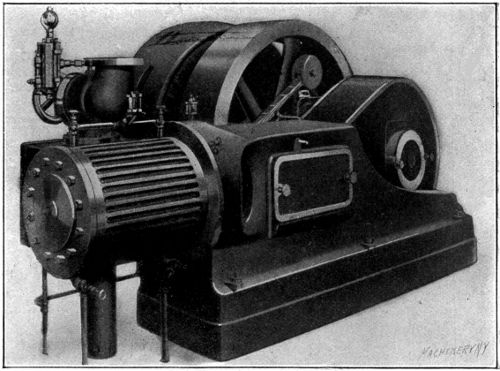
The Ball engine, as shown in Fig. 42, is a typical horizontal single valve high-speed engine with a direct-connected dynamo. It is very rigid in design and especially compact for the power developed. The valve is of the double-ported type shown in Fig. 2, having a cover plate for removing the steam pressure from the back of the valve. The piston is hollow with internal ribs similar to that shown in Fig. 29, and is provided with spring packing rings carefully fitted in place. The governor is of the shaft type, having only one weight instead of two, as shown in Fig. 37.
The Ball engine, as shown in Fig. 42, is a standard horizontal single valve high-speed engine with a directly connected dynamo. It's designed to be very rigid and is particularly compact for the power it generates. The valve is a double-ported type as shown in Fig. 2, which includes a cover plate for releasing the steam pressure from the back of the valve. The piston is hollow and features internal ribs similar to those shown in Fig. 29, and is equipped with spring packing rings that are carefully fitted in place. The governor is a shaft type with only one weight instead of two, as shown in Fig. 37.
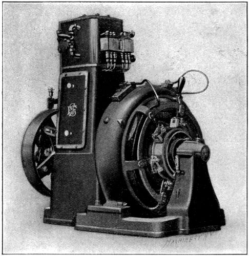
The Sturtevant engine shown in Fig. 43 is a vertical high-speed engine of a form especially adapted to electrical work. Engines of this general design are made in a variety of sizes, and are often used on account of the small floor space required. In the matter of detail, such as valves, governors, etc., they do not differ materially from the high-speed horizontal engine.
The Sturtevant engine shown in Fig. 43 is a vertical high-speed engine specifically designed for electrical work. Engines of this type come in various sizes and are often preferred due to the minimal floor space they occupy. In terms of details, like valves, governors, and so on, they are pretty much the same as high-speed horizontal engines.
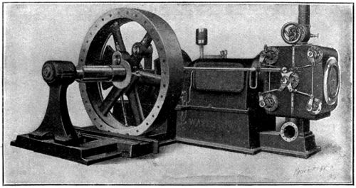
Fig. 44. Moderate Speed Engine of the Four-valve Type
Fig. 44. Moderate Speed Engine of the Four-valve Type
Fig. 44 illustrates a moderate-speed engine of the four-valve type. These engines are built either with flat valves, or with positively driven rotary or Corliss valves, the latter being used in the engine shown. It will be noticed that the drop-lever and dash-pot arrangement is omitted, the valves being both opened and closed by means of the wrist-plate and its connecting rods. This arrangement is used on account of the higher speed at which the engine is run, the regular Corliss valve gear being limited to comparatively low speeds. All engines of this make are provided with an automatic system of lubrication.[38] The oil is pumped through a filter to a central reservoir, seen above the center of the engine, and from here delivered to all bearings by gravity. The pump is attached to the rocker arm, and therefore easily accessible for repairs.
Fig. 44 shows a moderate-speed engine with a four-valve design. These engines can be made with either flat valves or driven rotary or Corliss valves, the latter being used in the engine depicted. You'll notice that the drop-lever and dash-pot setup is missing; the valves are opened and closed using the wrist-plate and its connecting rods. This design is used because of the higher speed at which the engine operates, as standard Corliss valve mechanisms are limited to lower speeds. All engines of this type come with an automatic lubrication system. The oil is pumped through a filter to a central reservoir located above the engine's center, and from there, it flows to all bearings by gravity. The pump is mounted on the rocker arm, making it easy to access for repairs.[38]
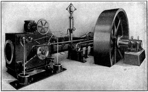
The standard Harris Corliss engine shown in Fig. 45, is typical of its class. It is provided with the girder type of frame, and with an outboard bearing mounted upon a stone foundation. The valve gear is of the regular Corliss type, driven by a single eccentric and wrist-plate. The dash pots are mounted on cast-iron plates set in the floor at the side of the engine, where they may be easily inspected. The governor is similar in construction to the one already described, and shown in Fig. 27. The four engines so far described are simple engines, the expansion taking place in a single cylinder. Figs. 46 to 48 show three different types of the compound engine.
The standard Harris Corliss engine shown in Fig. 45 is typical of its kind. It features a girder-type frame and has an outboard bearing mounted on a stone foundation. The valve gear follows the usual Corliss design, driven by a single eccentric and wrist plate. The dash pots are mounted on cast-iron plates set in the floor beside the engine for easy inspection. The governor is constructed similarly to the one already described and shown in Fig. 27. The four engines described so far are simple engines, with expansion occurring in a single cylinder. Figs. 46 to 48 show three different types of compound engines.
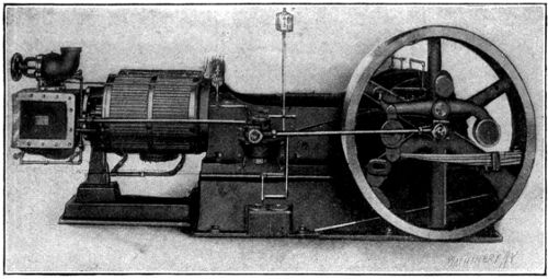
The engine shown in Fig. 46 is of a type known as the tandem compound. In this design the cylinders are in line, the low-pressure cylinder in front of the high-pressure, as shown. There is only one piston rod, the high-pressure and low-pressure pistons being mounted on the same rod. The general appearance of an engine of this design is the same as a simple engine, except for the addition of the high-pressure cylinder. The governor is of the shaft type and operates by changing the cut-off in the high-pressure cylinder. The cut-off in the low pressure cylinder is adjusted by hand to divide the load equally[39] between the two cylinders for the normal load which the engine is to carry.
The engine shown in Fig. 46 is a tandem compound type. In this design, the cylinders are aligned, with the low-pressure cylinder in front of the high-pressure one, as illustrated. There's only one piston rod, with both the high-pressure and low-pressure pistons mounted on it. Overall, an engine of this design looks similar to a simple engine, except for the added high-pressure cylinder. The governor is the shaft type and works by adjusting the cut-off in the high-pressure cylinder. The cut-off in the low-pressure cylinder is manually adjusted to evenly distribute the load between the two cylinders for the typical load the engine will handle.[39]
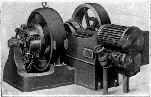
The engine shown in Fig. 47 is known as a duplex compound. In this design the high-pressure cylinder is placed directly below the low-pressure cylinder, as indicated, and both piston rods are attached to the same cross-head. The remainder of the engine is practically the same as a simple engine of the same type.
The engine shown in Fig. 47 is called a duplex compound. In this design, the high-pressure cylinder is located directly beneath the low-pressure cylinder, as shown, and both piston rods are connected to the same cross-head. The rest of the engine is essentially the same as a simple engine of that type.
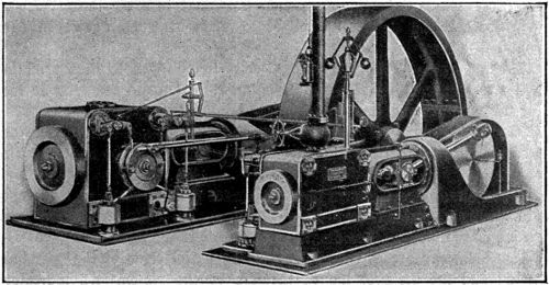
Fig. 48 shows a cross-compound engine of heavy design, built especially for rolling mill work. In this arrangement two complete engines are used, except for the main shaft and flywheel, which are common to both. The engine is so piped that the high-pressure cylinder exhausts into the low-pressure, through a receiver, the connection being under the floor and not shown in the illustration. One of the advantages of the cross-compound engine over other forms is that the cranks may be set 90 degrees apart, so that when one is on a dead center the other is approximately at its position of greatest effort.
Fig. 48 illustrates a robust cross-compound engine designed specifically for rolling mill operations. This setup utilizes two complete engines, except for the shared main shaft and flywheel. The engine is configured so that the high-pressure cylinder exhausts into the low-pressure cylinder via a receiver, with the connection running beneath the floor and not visible in the illustration. One benefit of the cross-compound engine compared to other types is that the cranks can be positioned 90 degrees apart, ensuring that when one crank is at a dead center, the other is close to its peak power position.
Selection of an Engine
The selection of an engine depends upon a number of conditions which vary to a considerable extent in different cases. Among these may be mentioned first cost, size and character of plant, available space, steam economy, and utilization of the exhaust steam. The question of first cost is usually considered in connection with that of operation, and items such as interest and depreciation are compared with the saving made through the saving in steam with high priced engines.
The choice of an engine depends on several factors that can differ significantly in various situations. These factors include the initial cost, size and type of the plant, available space, steam efficiency, and how well the exhaust steam is used. The initial cost is typically assessed alongside operational costs, and aspects like interest and depreciation are weighed against the savings generated from using more efficient, higher-priced engines.
The principal use of the stationary engine is confined to the driving of electric generators and the furnishing of motive power in shops and factories. For the first of these uses, in cases where floor space is limited, as in office buildings, and where the power does not exceed about 100 I. H. P., the simple non-condensing high-speed engine is probably employed more than any other type. For larger installations, a saving may usually be made by the substitution of the moderate-[41]speed four-valve engine. The question of simple and compound engines in this class of work depends largely upon the use made of the exhaust steam. In winter time the exhaust is nearly always utilized in the heating system, hence steam economy is not of great importance, and the simple engine answers all purposes at a smaller first cost. In localities where the heating season is comparatively short and fuel high, there is a decided advantage in using compound engines on account of their greater steam economy when operated within their economical range as regards load.
The main use of stationary engines is to power electric generators and provide motive power in shops and factories. For the first use, especially in places where space is tight, like office buildings, and where the power is around 100 I.H.P., the simple non-condensing high-speed engine is likely the most commonly used type. For larger setups, you can usually save money by switching to a moderate-speed four-valve engine. The choice between simple and compound engines for this type of work mostly depends on how the exhaust steam is used. In winter, the exhaust is almost always used in the heating system, so steam efficiency isn't very critical, and the simple engine serves all needs at a lower initial cost. In areas where the heating season is relatively short and fuel costs are high, using compound engines offers a clear advantage because they are more efficient in steam use when running at their optimal load range.
In large central plants where low cost of operation is always of first importance, it is common practice to use the best class of compound condensing engines of moderate or low speed. Those equipped with some form of Corliss valve gear are frequently found in this class of work. In the generation of power for shops and factories, where there is plenty of floor space, low-speed engines of the Corliss type are most commonly used. When space is limited, very satisfactory results may be obtained by using the moderate-speed four-valve engine. In deciding upon an engine for any particular case, the problem must be studied from all sides, and one be chosen which best answers the greatest number of requirements.
In large central plants where keeping operating costs low is always a top priority, it's common to use high-quality compound condensing engines that run at moderate or low speeds. Those equipped with some form of Corliss valve gear are often found in this type of work. For generating power in shops and factories, where there's plenty of floor space, low-speed Corliss engines are the standard choice. When space is tight, good results can also be achieved using moderate-speed four-valve engines. When selecting an engine for a specific application, it's important to evaluate the situation from all angles and choose the one that best meets the most requirements.
CHAPTER VI
STEAM ENGINE TESTING
The principal information sought in the usual test of a steam engine is:
The main information typically sought in a steam engine test is:
1. The indicated horsepower developed under certain standard conditions.
1. The indicated horsepower generated under specific standard conditions.
2. The friction of the engine, from which is determined the mechanical efficiency.[42]
2. The engine's friction, which determines its mechanical efficiency.[42]
3. The steam consumption per indicated horsepower.
3. The steam usage per indicated horsepower.
4. The general action of the valves.
4. The overall function of the valves.
5. The pressure conditions in the cylinder at different periods of the stroke.
5. The pressure conditions in the cylinder at various points during the stroke.
The ultimate object of an efficiency test is to determine the foot-pounds of work delivered by the engine per pound of coal burned in the boiler furnaces. The general method of finding the pounds of dry steam evaporated per pound of coal has been treated in Machinery’s Reference Series No. 67, “Boilers,” under the head of “Boiler Testing.” In the present case it is, therefore, only necessary to carry the process a step further and determine the foot-pounds of work developed per pound of steam.
The main goal of an efficiency test is to figure out how many foot-pounds of work the engine produces for each pound of coal burned in the boiler. The usual method for figuring out the pounds of dry steam produced per pound of coal is explained in Machinery Reference Series No. 67, “Boilers,” in the section on “Boiler Testing.” In this case, it's only necessary to go one step further and calculate the foot-pounds of work created per pound of steam.
The apparatus used in engine testing, in addition to that used in boiler testing, consists of a steam engine indicator and reducing device for taking diagrams, and a planimeter for measuring them afterwards. If the test is made independently of the boiler test, a calorimeter for measuring the amount of moisture in the steam should be added to the outfit.
The equipment used for testing engines, along with what's used for boiler testing, includes a steam engine indicator and a device to reduce pressure for taking diagrams, and a planimeter for measuring them later. If the test is done separately from the boiler test, a calorimeter to measure the moisture content in the steam should be included in the setup.
It has already been shown how a diagram may be made to represent graphically the work done in a steam engine cylinder during one stroke of the piston. The diagrams shown thus far have been theoretical or ideal cards constructed from assumed relations of the pressure acting and the distance moved through by the piston. An indicator is a device for making a diagram of what actually takes place in an engine cylinder under working conditions. Such a diagram shows the points of admission, cut-off, and release, and indicates accurately the pressures acting upon both sides of the piston at all points of the stroke.
It has already been demonstrated how a diagram can visually represent the work done in a steam engine cylinder during a single piston stroke. The diagrams presented so far have been theoretical or ideal charts based on assumed relationships between the pressure applied and the distance the piston moves. An indicator is a tool that creates a diagram of what truly occurs in an engine cylinder under operating conditions. This diagram displays the points of admission, cut-off, and release, and precisely indicates the pressures acting on both sides of the piston at every point in the stroke.
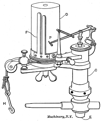
A common form of steam engine indicator is shown in Fig. 49. It consists of a cylinder C which is placed in communication at E with one end of the engine cylinder by a proper pipe connection, provided with a quick opening and closing cock or valve. The cylinder C contains a piston, above which is placed a coil spring of such strength that a given pressure per square inch acting upon the lower side of the piston will compress the spring a definite and known amount. Extending through the cap or head of cylinder C is a stem attached to the piston below, and connected by suitable levers with a pencil point P. The arrangement of the levers is such that a certain rise of the piston causes the point P to move upward in a vertical line a proportional amount.
A common type of steam engine indicator is shown in Fig. 49. It consists of a cylinder C that is connected at E to one end of the engine cylinder through a pipe, equipped with a quick-opening and closing valve. Inside the cylinder C is a piston, and above it is a coil spring that is strong enough so that a specific pressure per square inch acting on the bottom of the piston will compress the spring by a known amount. Coming through the cap or head of cylinder C is a stem attached to the piston below, which is linked by appropriate levers to a pencil point P. The arrangement of the levers is designed so that a certain rise of the piston causes the point P to move up in a straight line by a proportional amount.
The springs used above the piston vary in strength, and are designated as 20-pound, 40-pound, 60-pound, etc. A 20-pound spring is of such strength that a pressure of 20 pounds per square inch, acting beneath the piston in cylinder C, will raise the pencil point 1 inch. With a 40-pound spring, a pressure of 40 pounds per square inch will be required to raise the pencil 1 inch, and so on for the other strengths of spring.
The springs above the piston come in different strengths, labeled as 20-pound, 40-pound, 60-pound, and so on. A 20-pound spring is strong enough that a pressure of 20 pounds per square inch, pushing up from beneath the piston in cylinder C, will lift the pencil point 1 inch. With a 40-pound spring, you need a pressure of 40 pounds per square inch to raise the pencil by 1 inch, and this pattern continues with the other spring strengths.
The hollow drum D rotates back and forth upon a vertical stem at its center, its motion being produced by the string H, which is [43]attached by means of a suitable reducing motion to the cross-head of the engine. The return motion to the drum is obtained from a coil spring contained within it and not shown. The paper upon which the diagram is to be drawn is wound around the drum D, and held in place by the spring clip F.
The hollow drum D swings back and forth on a vertical stem at its center, with its movement created by the string H, which is [43]attached through a suitable reducing mechanism to the engine's cross-head. The drum's return motion comes from a coil spring inside it that isn’t shown. The paper for the diagram is wrapped around the drum D and secured with the spring clip F.
In taking an indicator card, the length of stroke must be reduced to come within the limits of the drum, that is, it must be somewhat less than the circumference of drum D. In practice, the diagram is commonly made from 3 to 4 inches in length. There are a number of devices in use for reproducing the stroke of the engine on a smaller scale. The most accurate consists of a series of pulleys over which the cord passes on its way from the cross-head to the indicator drum.
In using an indicator card, the stroke length must be shortened to fit within the drum limits, meaning it should be slightly less than the circumference of drum D. In practice, the diagram is usually about 3 to 4 inches long. There are several tools available for displaying the engine's stroke on a smaller scale. The most precise method involves a series of pulleys through which the cord travels from the cross-head to the indicator drum.
The indicator is connected with the engine cylinder by means of special openings tapped close to the heads and either plugged or closed by means of stop-cocks when not in use. In some cases two indicators are used, one being connected to each end of the cylinder, while in others a single indicator is made to answer the purpose by being so piped that it can be connected with either end by means of a three-way cock. After the indicator is connected and the cord adjusted to give the proper motion to the drum, a card is attached, after which the three-way cock is opened and steam allowed to blow through the indicator to warm it up. The cock is now closed and the pencil pressed against the drum to get the so-called atmospheric line. The cock is again opened, and the pencil pressed lightly against the drum during one complete revolution of the engine. The cock is then thrown over to connect the indicator with the other end of the cylinder and the operation is repeated.
The indicator is connected to the engine cylinder through special ports tapped close to the heads, which are either plugged or closed with stop-cocks when not in use. Sometimes, two indicators are used—one for each end of the cylinder—while in other cases, a single indicator can be designed to serve both ends by being piped with a three-way cock. After connecting the indicator and adjusting the cord for the correct movement of the drum, a card is attached. Then, the three-way cock is opened to let steam flow through the indicator to warm it up. The cock is closed, and the pencil is pressed against the drum to establish the so-called atmospheric line. Next, the cock is opened again, and the pencil is lightly pressed against the drum during one complete revolution of the engine. Finally, the cock is switched to connect the indicator with the other end of the cylinder, and the process is repeated.
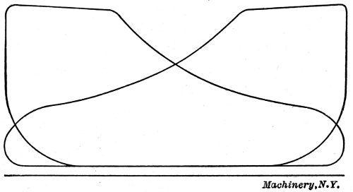
The indicator card obtained in this way is shown in Fig. 50. It is sometimes preferred to take the diagrams of the two ends on separate cards, but it is simpler to take them both on the same one, and also easier to compare the working of the two ends of the cylinder.
The indicator card created this way is shown in Fig. 50. Sometimes, it's preferred to have the diagrams of the two ends on separate cards, but it's simpler to have them both on the same card, and it's also easier to compare the operation of the two ends of the cylinder.
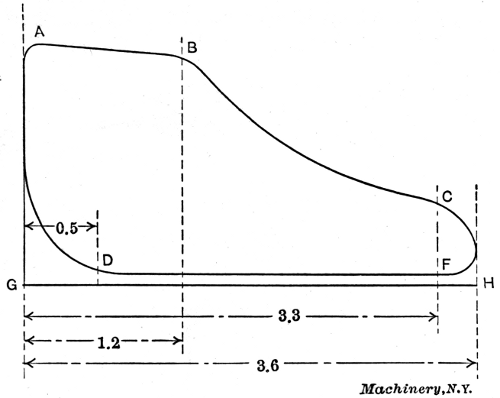
Fig. 51. Diagram for Illustrating Method of Computation
Fig. 51. Diagram for Illustrating Method of Calculation
The analysis of a card for practical purposes is shown in Fig. 51. Suppose, for example, that the length of the diagram measures 3.6 inches; the distance to the point of cut-off is 1.2 inch; and the distance to the point of release is 3.3 inches. Then, by dividing 1.2 by 3.6, the cut-off is found to occur at 1.2 ÷ 3.6 = 1⁄3 of the stroke. Release[44] occurs at 3.3 ÷ 3.6 = 0.92 of the stroke. Compression begins at (3.6 - 0.5) ÷ 3.6 = 0.86 of the stroke. The diagrams shown in Figs. 50 and 51 are from non-condensing engines, and the back-pressure line is therefore above the atmospheric line, as indicated.
The analysis of a card for practical purposes is shown in Fig. 51. Suppose, for example, that the length of the diagram is 3.6 inches; the distance to the cut-off point is 1.2 inches; and the distance to the release point is 3.3 inches. Then, by dividing 1.2 by 3.6, the cut-off occurs at 1.2 ÷ 3.6 = 1⁄3 of the stroke. Release[44] occurs at 3.3 ÷ 3.6 = 0.92 of the stroke. Compression begins at (3.6 - 0.5) ÷ 3.6 = 0.86 of the stroke. The diagrams shown in Figs. 50 and 51 are from non-condensing engines, so the back-pressure line is above the atmospheric line, as indicated.
The indicator diagram gives a means of determining the mean effective pressure, from which the power of the engine can be found from the previously given equation
The indicator diagram provides a way to determine the mean effective pressure, from which the engine's power can be calculated using the previously provided equation.
| APLN | |
| I. H. P. = | ———. |
| 33,000 |
The method of determining the mean effective pressure is as follows: First measure the area of the card in square inches, by means of a planimeter (an instrument described later), and divide this area by the length in inches. This gives the mean ordinate; the mean ordinate, in turn, multiplied by the strength of spring used, will give the mean effective pressure in pounds per square inch. For example, suppose that the card shown in Fig. 51 is taken with a 60-pound spring, and that the area, as measured by a planimeter, is found to be 2.6 square inches. Dividing the area by the length gives 2.6 ÷ 3.6 = 0.722 inch as the mean ordinate, and this multiplied by the strength of spring gives a mean effective pressure of 0.722 × 60 = 43.3 pounds per square inch.
The way to figure out the mean effective pressure is as follows: First, measure the area of the card in square inches using a planimeter (an instrument explained later), and divide this area by the length in inches. This gives you the mean ordinate; the mean ordinate, when multiplied by the strength of the spring used, will give you the mean effective pressure in pounds per square inch. For example, let’s say the card shown in Fig. 51 was taken with a 60-pound spring, and the area measured with a planimeter is 2.6 square inches. Dividing the area by the length gives 2.6 ÷ 3.6 = 0.722 inch as the mean ordinate, and multiplying this by the strength of the spring results in a mean effective pressure of 0.722 × 60 = 43.3 pounds per square inch.
In practice, diagrams taken from the two ends of the cylinder usually vary more or less, due to inequalities in the valve action. Again, the effective area of the piston on the crank end is less than that on the head end, by an amount equal to the area of the piston rod. For these reasons it is customary to compute the mean effective pressure of all the cards separately, and take, for use in the formula, the average of the various computations. The corrected value of the piston area is, as already stated, equal to (2A - a)⁄2, in which A is the area of the piston, and a the area of the piston rod. Substituting these values for A and P in the formula, together with the length of stroke and average number of revolutions per minute, the indicated horsepower is easily computed.
In practice, diagrams taken from both ends of the cylinder usually differ somewhat due to inconsistencies in the valve action. Additionally, the effective area of the piston on the crank end is smaller than that on the head end by an amount equal to the area of the piston rod. For these reasons, it’s common to calculate the mean effective pressure of all the cards separately and use the average of the various calculations in the formula. The adjusted value of the piston area is, as mentioned, equal to (2A - a)⁄2, where A is the area of the piston and a is the area of the piston rod. By replacing these values for A and P in the formula, along with the length of the stroke and the average number of revolutions per minute, the indicated horsepower can be easily calculated.
[45]In making an ordinary test, diagrams are taken from both ends of the cylinder at 10-minute intervals for several hours, depending upon the accuracy required. The revolutions of the engine are counted for two or three-minute periods each time a pair of cards are taken, or still better, an automatic counter is used for the run, from which the average number of revolutions per minute may be determined.
[45]For a standard test, diagrams are collected from both ends of the cylinder every 10 minutes for several hours, depending on the needed accuracy. The engine's revolutions are counted in two or three-minute intervals each time a pair of cards is collected, or even better, an automatic counter is used during the run to determine the average number of revolutions per minute.
The friction of the engine is determined by taking a pair of cards while “running light,” that is, with the belt thrown off, or the engine uncoupled, from the dynamo, if part of a direct-connected outfit. The friction load is then computed in horsepower from the indicator cards, and subtracted from the indicated horsepower when loaded. Thus we obtain the delivered or brake horsepower. The delivered horsepower divided by the indicated horsepower gives the mechanical efficiency. This may be expressed in the form of an equation as follows:
The engine's friction is measured by using a pair of cards while "running light," meaning with the belt off or the engine disconnected from the dynamo if it's part of a direct-connected setup. The friction load is then calculated in horsepower from the indicator cards and subtracted from the indicated horsepower when loaded. This gives us the delivered or brake horsepower. Dividing the delivered horsepower by the indicated horsepower gives us the mechanical efficiency. This can be expressed as an equation as follows:
| I. H. P. - friction loss | |
| ———————— | = mechanical efficiency. |
| I. H. P. |
Planimeter
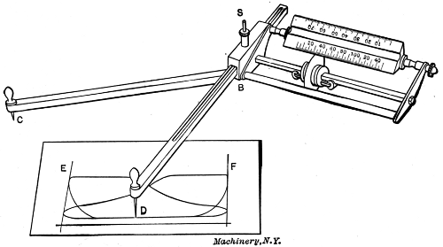
The planimeter is an instrument for measuring areas in general, and especially for measuring the areas of indicator cards. Some forms give the mean effective pressure directly, without computations, by changing the scale to correspond with the spring used in the indicator. A planimeter of this type is shown in Fig. 52. The method of manipulating this instrument is as follows. Set the arm BD equal to the length of the card EF, by means of the thumb screw S, and set the wheel at zero on the scale, which must correspond to the spring used in the indicator. Next, place the point D at about the middle of the area to be measured, and set point C so that the arm CB shall be approximately at right angles with BD. Then move D to the upper left-hand corner of the diagram, and with the left hand move C either to the right or left until the wheel comes back exactly to the zero point on the scale; then press the point firmly into the paper. Now, go[46] around the outline of the diagram with point D from left to right, finishing exactly at the starting point. The mean effective pressure may now be read from the scale opposite the edge of the wheel.
The planimeter is a tool used to measure areas in general, and particularly for measuring the areas of indicator cards. Some models provide the mean effective pressure directly, without the need for calculations, by adjusting the scale to match the spring used in the indicator. An example of this type of planimeter is shown in Fig. 52. Here's how to use this instrument: First, set the arm BD to match the length of the card EF using the thumb screw S, and adjust the wheel to zero on the scale, ensuring it corresponds to the spring in the indicator. Next, position point D approximately at the center of the area you're measuring, and adjust point C so the arm CB is roughly at a right angle to BD. Then, move point D to the upper left corner of the diagram, and with your left hand, adjust C either to the right or left until the wheel returns exactly to the zero point on the scale; then press the point firmly into the paper. Now, trace around the outline of the diagram with point D from left to right, finishing exactly at the starting point. The mean effective pressure can now be read from the scale next to the edge of the wheel.
When very accurate results are required, the tracer point D may be passed over the diagram several times, and the reading divided by the number of times it is thus passed around. With short cards, 3 inches and under in length, it is best to make the arm BD twice the length of the card, and go around the diagram twice, taking the reading directly from the scale as in the first case.
When highly accurate results are needed, the tracer point D can be moved over the diagram multiple times, and then the reading is divided by the number of times it was passed. For shorter cards, 3 inches or less in length, it's best to make the arm BD twice the length of the card and go around the diagram twice, taking the reading directly from the scale as described in the first case.
Determining Steam Consumption
When it is desired to determine accurately the water rate of an engine, a boiler test should be carried on simultaneously with the test upon the engine, from which the pounds of dry steam supplied may be determined as described in Machinery’s Reference Series No. 67, “Boilers.” Knowing the average weight of steam supplied per hour for the run, and the average indicated horsepower developed during the same period, the water rate of the engine is easily computed. Sometimes the average cylinder condensation for a given type and make is known for certain standard conditions. In this case an approximation may be made from an indicator diagram which represents the average operation of the engine during the test.
When you want to accurately determine the water rate of an engine, a boiler test should be conducted at the same time as the engine test, allowing you to find out how many pounds of dry steam are supplied, as outlined in Machinery Reference Series No. 67, “Boilers.” By knowing the average weight of steam supplied per hour during the run and the average indicated horsepower produced during that time, you can easily calculate the water rate of the engine. Sometimes, the average cylinder condensation for a specific type and make is known for certain standard conditions. In that case, an estimation can be made from an indicator diagram representing the engine's average operation during the test.
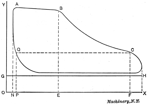
A diagram shows by direct measurement the pressure and volume at any point of the stroke, and the weight of steam per cubic foot for any given pressure may be taken directly from a steam table. The method, then, of finding the weight of steam at any point in the stroke is to find the volume in cubic feet, including the clearance and piston displacement to the given point, which must be taken at cut-off or later, and to multiply this by the weight per cubic foot corresponding to the pressure at the given point measured on the diagram. As this includes the steam used for compression, it must be corrected, as follows, to obtain the actual weight used per stroke. Take some con[47]venient point on the compression curve, as Q, in Fig. 53; measure its absolute pressure from the vacuum line OX and compute the weight of steam to this point. Subtract this weight from that computed above for the given point on the expansion line, and the result will be the weight of steam used per stroke. The best point on the expansion line to use for this purpose is just before release, both because the maximum amount of leakage has taken place, and also because of the re-evaporation of a portion of the steam condensed during admission. The actual computation of the steam consumption from an indicator diagram is best shown by a practical illustration.
A diagram directly measures the pressure and volume at any point of the stroke, and the weight of steam per cubic foot for any given pressure can be taken directly from a steam table. To find the weight of steam at any point in the stroke, determine the volume in cubic feet, including the clearance and piston displacement up to that point, which should be measured at cut-off or later, and multiply this by the weight per cubic foot corresponding to the pressure at that point shown on the diagram. Since this includes the steam used for compression, it needs to be adjusted to get the actual weight used per stroke. Choose a convenient point on the compression curve, labeled Q, in Fig. 53; measure its absolute pressure from the vacuum line OX and calculate the weight of steam to this point. Subtract this weight from the weight calculated earlier for the specific point on the expansion line, and the result will give the weight of steam used per stroke. The ideal point on the expansion line for this calculation is just before release, because that’s when the maximum leakage has occurred, and a portion of the steam condensed during admission re-evaporates. The actual calculation of steam consumption from an indicator diagram is best illustrated with a practical example.
Example—Let Fig. 53 represent a diagram taken from the head end of a 16 × 30-inch non-condensing engine, running at a speed of 150 revolutions per minute; the card is taken with a 60-pound spring; the clearance of the engine is 6 per cent; the average cylinder condensation is 20 per cent of the total steam consumption; the diameter of the piston rod is 3 inches.
Example—Let Fig. 53 represent a diagram from the front end of a 16 × 30-inch non-condensing engine, operating at 150 revolutions per minute; the card is recorded with a 60-pound spring; the engine's clearance is 6 percent; the average cylinder condensation is 20 percent of the total steam consumption; the diameter of the piston rod is 3 inches.
Measuring the card with a planimeter shows the mean effective pressure to be 48.2 pounds. The area of the piston is 201 square inches; the area of the piston rod is 7 square inches; hence, the average piston area = (2 × 201) - 7⁄2 = 198 square inches, approximately. Then
Measuring the card with a planimeter indicates that the mean effective pressure is 48.2 pounds. The piston area is 201 square inches; the piston rod area is 7 square inches; therefore, the average piston area = (2 × 201) - 7⁄2 = about 198 square inches. Then
| 198 × 48.2 × 2.5 × 300 | ||
| I. H. P. = | —————————— | = 217. |
| 33,000 |
In Fig. 53, GH is the atmospheric line; OX is the line of vacuum or zero pressure, drawn so that GO = 14.7 pounds on the scale; and OY is the clearance line, so drawn that ON = 0.06 NX. The line PQ is drawn from OX to some point on the compression line, as at Q. From C, a point on the expansion line, just before release, the line CF is drawn perpendicular to OX. The following dimensions are now carefully measured from the actual diagram (not the one shown in the illustration), with the results given:[48]
In Fig. 53, GH represents the atmospheric line; OX indicates the vacuum or zero pressure line, set so that GO equals 14.7 pounds on the scale; and OY is the clearance line, drawn so that ON is 0.06 NX. The line PQ extends from OX to a point on the compression line, such as Q. From C, a point on the expansion line just before release, the line CF is drawn perpendicular to OX. The following dimensions are now carefully measured from the actual diagram (not the one shown in the illustration), with the results provided:[48]
| OX = 3.71 | OP = 0.42 |
| NX = 3.50 | CF = 0.81 |
| OF = 3.20 | QP = 0.81 |
On the indicator diagram, being taken with a 60-pound spring, all vertical distances represent pounds per square inch, in the ratio of 60 pounds per inch of height. The stroke of the engine is 30 inches or 2.5 feet. The length of the diagram NX is 3.5 inches; hence, each inch in length represents 2.5⁄3.5 = 0.71 feet. From the above it is evident that vertical distances in Fig. 53 must be multiplied by 60 to reduce them to pounds pressure per square inch, and that horizontal distances must be multiplied by 0.71 to reduce them to feet. Making these reductions gives:
On the indicator diagram, which is taken with a 60-pound spring, all vertical distances represent pounds per square inch in the ratio of 60 pounds per inch of height. The stroke of the engine is 30 inches or 2.5 feet. The length of the diagram NX is 3.5 inches; therefore, each inch in length represents 2.5⁄3.5 = 0.71 feet. From this, it’s clear that vertical distances in Fig. 53 must be multiplied by 60 to convert them to pounds of pressure per square inch, and that horizontal distances must be multiplied by 0.71 to convert them to feet. Making these adjustments gives:
| OX = 2.63 feet. | OP = 0.30 foot. |
| NX = 2.49 feet. | CF = 48.6 pounds. |
| OF = 2.27 feet. | QP = 48.6 pounds. |
As a card from the head end of the cylinder is taken to avoid corrections for the piston rod, the area is 201 square inches or 1.4 square foot. With the above data the volume and weight of the steam in the cylinder can be computed at any point in the stroke. When the piston is at C, the volume is 1.4 × 2.27 = 3.18 cubic feet. When the piston is at Q, the volume is 1.4 × 0.30 = 0.42 cubic foot. From a steam table the weight of a cubic foot of steam at 48.6 pounds absolute pressure is found to be 0.116 pounds. Therefore, the weight of steam present when the piston is at C is 3.18 × 0.116 = 0.369 pounds. The weight of steam present when the piston is at Q is 0.42 × 0.116 = 0.049 pound. That is the weight of steam in the cylinder at release is 0.369 pound, and the weight kept at exhaust closure for compression is 0.049 pound.
As a card from the front end of the cylinder is used to avoid adjustments for the piston rod, the area is 201 square inches, or 1.4 square feet. Using this information, the volume and weight of the steam in the cylinder can be calculated at any point during the stroke. When the piston is at C, the volume is 1.4 × 2.27 = 3.18 cubic feet. When the piston is at Q, the volume is 1.4 × 0.30 = 0.42 cubic feet. According to a steam table, the weight of a cubic foot of steam at 48.6 pounds of absolute pressure is found to be 0.116 pounds. Therefore, the weight of steam present when the piston is at C is 3.18 × 0.116 = 0.369 pounds. The weight of steam present when the piston is at Q is 0.42 × 0.116 = 0.049 pounds. Thus, the weight of steam in the cylinder at release is 0.369 pounds, and the weight maintained at exhaust closure for compression is 0.049 pounds.
The weight exhausted per stroke is therefore 0.369 - 0.049 = 0.32 pound. The number of strokes per hour is 150 × 2 × 60 = 18,000, from which the steam accounted for by the diagram is found to be 18,000 × 0.32 = 5760 pounds, or 5760 ÷ 217 = 26.5 pounds per indicated horsepower per hour. If the cylinder condensation for this type of engine is 20 per cent of the total steam consumption, the water rate will be 26.5 ÷ 0.8 = 33.1 pounds per indicated horsepower per hour.
The weight used up per stroke is therefore 0.369 - 0.049 = 0.32 pounds. The number of strokes per hour is 150 × 2 × 60 = 18,000, which means the steam accounted for by the diagram is 18,000 × 0.32 = 5,760 pounds, or 5,760 ÷ 217 = 26.5 pounds per indicated horsepower per hour. If the cylinder condensation for this type of engine is 20 percent of the total steam consumption, the water rate will be 26.5 ÷ 0.8 = 33.1 pounds per indicated horsepower per hour.
In the present case it has been assumed, for simplicity, that the head- and crank-end diagrams were exactly alike, except for the piston rod. Ordinarily, the above process should be carried out for both head and crank ends, and the results averaged.
In this case, it's assumed for simplicity that the head and crank end diagrams were exactly the same, except for the piston rod. Usually, this process should be done for both the head and crank ends, and the results averaged.
Transcriber's note:
Transcriber's note:
- Inconsistencies have not been corrected (hyphenated vs non-hyphenated or spaced words), except horse-power (changed to horsepower) and cut off (changed to cut-off) as elsewhere.
- Minor typographical errors have been corrected.
- In-line multi-line formulas have been changed to single-line formulas, where necessary with the addition of brackets to prevent ambiguity.
- Most tables and illustrations have been moved to the paragraph where they are first discussed or mentioned.
Download ePUB
If you like this ebook, consider a donation!