This is a modern-English version of Physics, originally written by Cope, Thomas D. (Thomas Darlington), Smith, Charles H. (Charles Henry), Tower, Willis E. (Willis Eugene), Turton, Charles M. (Charles Mark).
It has been thoroughly updated, including changes to sentence structure, words, spelling,
and grammar—to ensure clarity for contemporary readers, while preserving the original spirit and nuance. If
you click on a paragraph, you will see the original text that we modified, and you can toggle between the two versions.
Scroll to the bottom of this page and you will find a free ePUB download link for this book.
PHYSICS
TOWER, SMITH, TURTON,
AND
COPE
TOWER, SMITH, TURTON,
AND
COPE
 (See p.441)
Three-color Printing
Y. Yellow print; negative created using a blue-violet filter. R. Crimson print; negative made with a green filter. RY. Crimson on yellow. B. Blue print; negative made using a red filter. YRB. Yellow, crimson, and blue combined; the final product. (Courtesy of Phototype Engraving Co., Philadelphia.)
PHYSICS
BY
BY
WILLIS E. TOWER, M. SCI. (Univ. of Illinois)
HEAD OF THE DEPARTMENT OF PHYSICS, ENGLEWOOD
HIGH SCHOOL, CHICAGO
WILLIS E. TOWER, M.S. (University of Illinois)
HEAD OF THE PHYSICS DEPARTMENT, ENGLEWOOD
HIGH SCHOOL, CHICAGO
CHARLES H. SMITH, M. E. (Cornell)
HEAD OF THE DEPARTMENT OF PHYSICS AND ASSISTANT
PRINCIPAL, HYDE PARK SCHOOL, CHICAGO
CHARLES H. SMITH, M. E. (Cornell)
HEAD OF THE DEPARTMENT OF PHYSICS AND ASSISTANT
PRINCIPAL, HYDE PARK SCHOOL, CHICAGO
CHARLES M. TURTON, A. M. (Syracuse)
HEAD OF THE DEPARTMENT OF PHYSICS, BOWEN
HIGH SCHOOL, CHICAGO
CHARLES M. TURTON, A. M. (Syracuse)
HEAD OF THE DEPARTMENT OF PHYSICS, BOWEN
HIGH SCHOOL, CHICAGO
IN COLLABORATION WITH
IN PARTNERSHIP WITH
THOMAS D. COPE, Ph.D. (Pennsylvania)
ASSISTANT PROFESSOR OF PHYSICS, UNIVERSITY
OF PENNSYLVANIA
THOMAS D. COPE, Ph.D. (Pennsylvania)
ASSISTANT PROFESSOR OF PHYSICS, UNIVERSITY
OF PENNSYLVANIA
BASED UPON
PRINCIPLES OF PHYSICS
BY
TOWER, SMITH and TURTON
BASED ON
Principles of Physics
BY
TOWER, SMITH, and TURTON
WITH 7 PLATES AND 448 OTHER ILLUSTRATIONS
WITH 7 PLATES AND 448 OTHER ILLUSTRATIONS
PHILADELPHIA
P. BLAKISTON'S SON & CO.
1012 WALNUT STREET
PHILADELPHIA
P. BLAKISTON'S SON & CO.
1012 WALNUT STREET
Copyright, 1920, by P. Blakiston's Son & Co.
Copyright, 1920, by P. Blakiston's Son & Co.
PREFACE
In the preparation of this text, the pupil, his experience, needs, and interests have been constantly kept in mind. The order of topics, illustrations, and problems have been selected with the purpose of leading the pupil into a clear understanding of the physical phenomena continually taking place about him.
In preparing this text, the student, their experiences, needs, and interests have been consistently considered. The arrangement of topics, illustrations, and problems have been chosen to help the student gain a clear understanding of the physical phenomena that are constantly happening around them.
The recommendations and conclusions reached by the "New Movement in the Teaching of Physics" have been incorporated into the book as a whole. These conclusions indicate that the most efficient teaching in physics involves a departure from the quantitative, mathematical methods of presentation that were in general use a dozen or more years ago, toward a method better adapted to the capabilities, interests, and requirements of the young people in our physics classes.
The recommendations and conclusions from the "New Movement in the Teaching of Physics" have been included in the book overall. These conclusions suggest that the most effective way to teach physics now involves moving away from the quantitative, mathematical methods that were commonly used over a decade ago, towards an approach that is more suited to the abilities, interests, and needs of the young people in our physics classes.
The older methods are effective with a portion of the student body which has the greater mathematical ability and training, but they discourage a large majority of the pupils who are not gifted or prepared for severe mathematical analysis. For this reason, many of the more difficult mathematical demonstrations often given in physics texts are omitted. Most of the problems involve only the units employed in practical every-day measurements.
The traditional methods work well for some students who have strong math skills and training, but they discourage a lot of students who aren't naturally talented or ready for advanced math. Because of this, many of the more complex math proofs that are often included in physics textbooks are left out. Most of the problems only use the units found in everyday measurements.
The portions of Mechanics that are ordinarily so difficult for the average pupil are not taken up until he has covered considerable ground with which he is more or less familiar and not until he has become somewhat accustomed[Pg vi] to the methods of study and the technical terms of the subject.
The parts of Mechanics that are usually tough for the average student aren't tackled until they've gone over a lot of material they're somewhat familiar with, and only after they've gotten used[Pg vi] to the study methods and technical terms of the subject.
The pupil comes to the study of physics with a great number of experiences and impressions of physical phenomena continually occurring about him. In recognition of this fact, it has been thought best to consider first the explanation of common things well known to all pupils, such as the diffusion of gases, evaporation of liquids, expansion of bodies when heated, and capillary action. Since the molecular theory of matter is now supported by so many conclusive evidences, we have not hesitated to make free use of it in the early chapters. The applications of this theory are extremely helpful in explaining every-day phenomena. Our experience shows that beginners in physics understand and apply this theory without difficulty.
The student approaches the study of physics with a wealth of experiences and observations about physical phenomena happening all around them. Acknowledging this, we decided to start with explanations of common concepts familiar to all students, like the diffusion of gases, evaporation of liquids, the expansion of materials when heated, and capillary action. Given that the molecular theory of matter is now backed by numerous solid pieces of evidence, we have confidently incorporated it in the early chapters. The applications of this theory greatly aid in explaining everyday phenomena. Our experience indicates that beginners in physics easily understand and apply this theory.
The illustrations and drawings have been selected from a pedagogical rather than a spectacular point of view. Practically all of them are new. The problems and exercises have been selected for the distinct purpose of illustrating the principles taught in the text and for their practical applications.
The illustrations and drawings have been chosen from an educational rather than a flashy perspective. Almost all of them are new. The problems and exercises have been selected specifically to demonstrate the principles taught in the text and their practical uses.
Many direct applications to common every-day experiences are given in order to connect the subject matter with the home environment and daily observation of physical phenomena. Some phenomena are mentioned without detailed explanation as it is felt that the presentation of these subjects in this manner is better for this grade of student than a complete analysis.
Many direct applications to everyday experiences are provided to link the subject matter with the home environment and daily observations of physical phenomena. Some phenomena are referenced without detailed explanations because it's believed that presenting these topics this way is more effective for this grade of student than a complete analysis.
Some of the special features of the text may be briefly summarized as follows:
Some of the unique features of the text can be briefly summarized as follows:
(A) Simplicity of presentation is emphasized. The methods of attack, the illustrations and examples employed in developing the subjects are particularly adapted to beginners in physics.
(A) Simplicity of presentation is emphasized. The methods of approach, the illustrations, and examples used in explaining the topics are specifically tailored for beginners in physics.
(B) The text is divided into some seventy-seven sections, each containing material enough for one recitation.
(B) The text is divided into about seventy-seven sections, each containing enough material for one recitation.
(C) Each of these sections is summarized by a list of important topics which point out to the pupil the principles and subject matter requiring most careful attention. The lists of important topics are also of assistance to the teacher in assigning recitations.
(C) Each of these sections is summarized by a list of important topics that highlight the principles and content that require the most attention from the student. The lists of important topics also help the teacher when assigning recitations.
(D) The problems and practical exercises emphasize physical principles as distinguished from mathematical training. A list of exercises is placed at the end of the several sections. They are in sufficient number to permit testing at many points and of a choice of problems by teachers.
(D) The problems and practical exercises focus on physical principles rather than on math skills. A list of exercises is provided at the end of each section. There are enough exercises to allow for testing at various points and give teachers a selection of problems to choose from.
The authors wish to express their appreciation for suggestions and helpful criticisms to many who have read the text in manuscript or proof. Especially to Professor A. P. Carman of the University of Illinois and his associate, Professor F. R. Watson, who have gone carefully over the whole text; and to Mr. Chas. M. Brunson, Scott High School, Toledo, Ohio, Mr. Frank E. Goodell, North High School, Des Moines, Iowa, and to Mr. Walter R. Ahrens, Englewood High School, Chicago, for assistance in reading the proofs. Also to Mr. W. H. Collins, Jr., Bowen High School, Chicago, who supervised the preparation of drawings for the diagrams and figures; and to many firms and individuals that have courteously furnished material for illustrations.
The authors want to thank everyone who made suggestions and gave helpful feedback while reviewing the text in manuscript or proof. A special thanks goes to Professor A. P. Carman of the University of Illinois and his colleague, Professor F. R. Watson, who thoroughly reviewed the entire text; and to Mr. Chas. M. Brunson from Scott High School in Toledo, Ohio, Mr. Frank E. Goodell from North High School in Des Moines, Iowa, and Mr. Walter R. Ahrens from Englewood High School in Chicago for their help in reading the proofs. We also appreciate Mr. W. H. Collins, Jr. from Bowen High School in Chicago, who oversaw the preparation of drawings for the diagrams and figures; and to all the companies and individuals who generously provided material for the illustrations.
Willis E. Tower.
Charles H. Smith.
Charles M. Turton.
Willis Tower.
Charles H. Smith.
Charles M. Turton.
ON THE STUDY OF PHYSICS
When a pupil begins the study of Physics he has in his possession many bits of knowledge which are fundamental in the science. He has learned to throw a ball and can tell how a thrown ball moves. He has drawn out nails with a claw hammer. He has seen wood float and iron sink. He has sucked liquids up through straws. In his mother's kitchen, he sees water as ice, liquid, and steam. On a wintry day he reads the temperature on a thermometer. He sees sparks fly from car wheels when the brakes are applied. He has played with a horseshoe magnet, and has found the north by means of a compass. The telephone, the electric light and the motor he sees, and perhaps uses, many times a day. He dresses before a mirror, focuses his camera, watches the images at a moving picture show, and admires the colors of the rainbow. He has cast stones into water to watch the ripples spread, has shouted to hear the echo, and perhaps plays some musical instrument. These, and a thousand other things, are known to the intelligent and normal boy or girl who has reached the age at which the study of Physics is properly begun.
When a student starts studying Physics, they already have a good amount of basic knowledge about the subject. They've learned how to throw a ball and can describe how a thrown ball moves. They’ve used a claw hammer to pull out nails. They’ve watched wood float and iron sink. They’ve drunk liquids through straws. In their mom’s kitchen, they see water in the forms of ice, liquid, and steam. On a cold day, they check the temperature on a thermometer. They notice sparks fly from car wheels when the brakes are applied. They’ve played with a horseshoe magnet and used a compass to find north. They see the telephone, electric light, and motors, likely using them several times a day. They get dressed in front of a mirror, focus their camera, enjoy images at a movie theater, and admire the colors of a rainbow. They’ve thrown stones into water to watch the ripples spread, shouted to hear an echo, and maybe play a musical instrument. These, and countless other experiences, are familiar to any bright and typical boy or girl who has reached the age to begin studying Physics.
To a great extent even the terms used in the science are familiar to the beginner. He speaks of the horse-power of an engine, reads kilowatt-hours from the meter in the cellar, and may know that illuminating gas costs one dollar per thousand "cubic feet." "Ampere" and "volt" are words he frequently hears and sees.
To a large extent, even the terms used in science are familiar to beginners. They talk about the horsepower of an engine, read kilowatt-hours from the meter in the basement, and might know that gas costs one dollar per thousand "cubic feet." "Ampere" and "volt" are words they often hear and see.
When he takes up the study of Physics, the attitude of[Pg x] the student toward these familiar things and words must undergo a change. Casual information about them must be changed to sound knowledge, purposely acquired. Hazy notions about the meanings of words must be replaced by exact definitions. Bits of knowledge must be built into a structure in which each fact finds its proper place in relation to the others.
When he starts studying Physics, the student's attitude toward these familiar things and words must change. Casual knowledge about them needs to be transformed into solid understanding, intentionally gained. Vague ideas about the meanings of words must be replaced with precise definitions. Pieces of knowledge must be organized into a structure where each fact is properly related to the others.
The only agent which can accomplish these changes is the student himself. He must consciously and purposely seek the truth and must reflect upon it until he sees it in its relation to other truth. Upon him, and upon him alone, rests the final responsibility for the success or failure of his study.
The only person who can make these changes happen is the student himself. He must actively and intentionally pursue the truth and think about it until he understands how it relates to other truths. Ultimately, he alone holds the final responsibility for the success or failure of his study.
But the student is not without assistance. In his teacher he finds a guide to stimulate, to direct, and to aid his efforts, and a critic to point out wherein his efforts have failed and wherein they have succeeded. Weights, measures, and other apparatus are furnished to enable him to answer for himself questions which have arisen in his studies.
But the student isn’t left to figure things out on his own. His teacher acts as a guide to inspire, direct, and support his efforts, as well as a critic to highlight where he has fallen short and where he has succeeded. Tools, measurements, and other equipment are provided to help him find answers to the questions that have come up in his studies.
In addition to these the student has his text book, his teacher for his hours of private study. A good text book is an inspiring teacher in print. It directs attention to things familiar to the student through long experience, and inspires him to make a closer scrutiny of them. It invites him to observe, to analyze, to compare, to discover likenesses and differences in behavior. It questions him at every turn. Its ever repeated challenge reads, "Weigh and consider." It furnishes him needed information that he cannot otherwise acquire. It satisfies his desire to know, "By whom, where, when, and how was this first discovered?"
Along with this, the student has their textbook and their teacher for private study sessions. A good textbook is like an inspiring teacher in written form. It focuses on things the student has encountered many times before and encourages them to examine these things more closely. It prompts them to observe, analyze, compare, and find similarities and differences in behavior. It challenges them at every step, with the constant message, "Think critically and reflect." It provides essential information that they wouldn't be able to get otherwise. It fulfills their curiosity about "Who, where, when, and how was this first discovered?"
The student of Physics must never forget that he is studying not pages of text but the behavior and properties[Pg xi] of iron, water, mica, moving balls, pumps, boiling liquids, compressed air, mirrors, steam engines, magnets, dynamos, violins, flutes, and a host of other things. His studies should, whenever possible, be made first hand upon the things themselves. The text is an aid to study, never a substitute for the thing studied.
The physics student must always remember that they are studying not just words in a book but the behavior and properties[Pg xi] of materials like iron, water, mica, moving balls, pumps, boiling liquids, compressed air, mirrors, steam engines, magnets, dynamos, violins, flutes, and many other items. Whenever possible, their studies should involve direct interaction with the subjects themselves. The text is a helpful resource, but it can never replace the actual things being studied.
It is an excellent plan for each student to select some one thing for special study, the telephone for example. By observation, experiment, and reading, he may acquire a large amount of valuable information about such a subject while pursuing his course in Physics. Every part of the science will be found to bear some relation to it.
It’s a great idea for each student to choose one specific topic for deeper study, like the telephone, for instance. Through observation, experimentation, and reading, they can gain a wealth of valuable knowledge about that subject while going through their Physics curriculum. Every aspect of the science will connect to it in some way.
The student who takes up the study of Physics in the way suggested will find himself at the end of a year of study in possession of much new and valuable knowledge about the physical world in which he lives. By virtue of this knowledge he will be better able to enjoy the world, to control it, and to use it.
The student who engages with the study of Physics as suggested will find themselves at the end of the year with a lot of new and valuable knowledge about the physical world around them. Because of this knowledge, they will be better equipped to enjoy, control, and utilize the world.
Thomas D. Cope.
Thomas D. Cope.
Philadelphia.
Philadelphia.
CONTENTS
Chapter I. Introduction And Measurement. Page
Chapter I. Introduction and Measurement. Page
Chapter II. Molecular Forces And Motions.
Chapter II. Molecular Forces and Movements.
- (1) Molecular Motions in Gases 13
- (2) Molecular Motions in Liquids 18
- (3) Molecular Forces in Liquids 21
- (4) Molecular Forces in Liquids and Solids 27
- (5) Molecular Forces in Solids 31
Chapter III. Mechanics or Liquids.
Chapter 3. Mechanics of Liquids.
- (1) Liquid Pressure 36
- (2) Transmission of Liquid Pressure 41
- (3) Archimedes' Principle 47
- (4) Density and Specific Gravity 52
Chapter IV. Mechanics Of Gases.
Chapter IV. Gas Mechanics.
- (1) Weight and Pressure of the Air 55
- (2) Compressibility and Expansibility of the Air 62
- (3) Pneumatic Appliances 66
Chapter V. Force And Motion.
Chapter V. Force and Motion.
- (1) Force, how Measured and Represented 79
- (2) Motion. Newton's Laws 85
- (3) Resolution of Forces 96
- (4) Moment of Force and Parallel Forces 99
- (5) Gravitation and Gravity 103
- (6) Falling Bodies 109
- (7) The Pendulum 115
Chapter VI. Work And Energy.
Chapter 6. Work and Energy.
- (1) Work and Energy 119
- (2) Power and Energy 123
- (3) The Lever and Simple Machines 129
- (4) Wheel and Axle and Pulley 136
- (5) Efficiency and the Inclined Plane 142
- (6) Friction and its Uses 147
- (7) Water Power 152
Chapter VII. Heat, Its Production And Transmission.[Pg xiv]
Chapter VII. Heat: How It's Made and Shared.[Pg xiv]
- (1) Sources and Effects of Heat 159
- (2) Temperature and Expansion 162
- (3) Expansion of Gases, Liquids and Solids 167
- (4) Modes of Transmitting Heat 173
- (5) Convection, Heating and Ventilation 179
- (6) The Moisture in the Air, Hygrometry 191
- (7) Evaporation 196
Chapter VIII. Heat And Work.
Chapter 8. Heat and Work.
- (1) Heat Measurement and Specific Heat 200
- (2) Heat and Changes of State 205
- (3) Heat and Work 212
- (4) Heat Engines 222
Chapter IX. Magnetism.
Chapter 9. Magnetism.
- (1) General Properties of Magnets 228
- (2) Theory of Magnetism, Magnetic Fields 232
- (3) The Earth's Magnetism 238
Chapter XI. Static Electricity.
Chapter 11. Static Electricity.
- (1) Electrification and Electrical Charges 243
- (2) Electric Fields and Electrostatic Induction 247
- (3) Electric Theories, Distribution and Electric Charges 252
- (4) Potential, Capacity, and the Electric Condenser 257
- (5) Electrostatic Generators 262
Chapter XI. Electric Currents Produced By Voltaic Cells.
Chapter XI. Electric Currents Produced by Voltaic Cells.
- (1) Electrical Currents and Circuits 267
- (2) The Simple Voltaic Cell and its Action 270
- (3) Practical Voltaic Cells 274
Chapter XII. Magnetic Effects Of Electric Currents, And Electrical Measurements.
Chapter 12. Magnetic Effects of Electric Currents and Electrical Measurements.
- (1) The Magnetic Effect of Electric Currents 279
- (2) Electrical Measurements 289
- (3) Ohm's Law and Electrical Circuits 298
- (4) Grouping of Cells and Measuring Resistance 302
Chapter XIII. Chemical And Heat Effects Of Electric Currents.
Chapter 13: Chemical and Heat Effects of Electric Currents.
- (1) The Chemical Effect of Electric Currents 307
- (2) The Storage Battery and Electric Power 312
- (3) The Heat Effect of Electric Currents 318
Chapter XIV. Induced Currents.
Chapter 14. Induced Currents.
- (1) Electromagnetic Induction 326
- (2) The Dynamo and the Motor 335
- (3) The Induction Coil and the Transformer 343
- (4) The Telephone 349
Chapter XV. Sound.
Chapter 15. Sound.
- (1) Sound, Source, Speed, Media 354
- (2) Waves and Wave Motion 357
- (3) Intensity and Pitch of Sound 363
- (4) Musical Scales and Resonance 368
- (5) Interference, Beats, Vibration of Strings 374
- (6) Tone Quality, Vibrating Plates and Air Columns 384
Chapter XVI. Light.
Chapter 16. Light.
- (1) Rectilinear Propagation of Light 388
- (2) Photometry and Law of Reflection 393
- (3) Mirrors and Formation of Images 400
- (4) Refraction of Light 410
- (5) The Formation of Images by Lenses 416
- (6) Optical Instruments 423
- (7) Color and Spectra 430
- (8) Nature of Light 442
Chapter XVII. Invisible Radiations.
Chapter 17. Invisible Radiations.
- (1) Electric waves and Radioactivity 448
Chapter XVIII. Wireless Telephony And Alternating Currents.
Chapter 18. Wireless Phone Communication and Alternating Currents.
CHAPTER I
INTRODUCTION AND MEASUREMENT
INTRO AND MEASUREMENT
(1) Intro
1. Physics, an Explanation of Common Things.—Many students take up the study of physics expecting to see wonderful experiments with the "X" rays, wireless telegraphy, dynamos, and other interesting devices. Others are dreading to begin a study that to them seems strange and difficult, because they fear it deals with ideas and principles that are beyond their experience and hard to comprehend.
1. Physics, an Explanation of Common Things.—Many students start studying physics expecting to see amazing experiments with X-rays, wireless communication, generators, and other cool devices. Others are anxious about beginning a subject that feels strange and challenging to them because they worry it involves concepts and principles that are beyond their understanding and hard to grasp.
Each of these classes is surprised to learn that physics is mainly an explanation of common things. It is a study that systematizes our knowledge of the forces and changes about us; such as the pull of the earth, the formation of dew, rain and frost, water pressure and pumps, echoes and music, thermometers and engines, and many other things about us with which people are more or less familiar. Physics is like other school subjects, such as mathematics and language, in having its own peculiar vocabulary and methods of study; these will be acquired as progress is made in the course.
Each of these classes is surprised to discover that physics is mostly an explanation of everyday things. It's a field that organizes our understanding of the forces and changes around us, like the pull of the Earth, the formation of dew, rain and frost, water pressure and pumps, echoes and music, thermometers and engines, and many other familiar concepts. Physics is similar to other school subjects, such as math and language, in having its own unique vocabulary and ways of studying; these will be learned as students advance through the course.
The most useful habit that the student of physics can[Pg 2] form is that of connecting or relating each new idea or fact that is presented to him to some observation or experience that will illustrate the new idea. This relating or connecting of the new ideas to one's own personal experience is not only one of the best known means of cultivating the memory and power of association, but it is of especial help in a subject such as physics, which deals with the systematic study and explanation of the facts of our every-day experience.
The most helpful habit that a physics student can[Pg 2] develop is linking each new idea or fact they encounter to some observation or experience that illustrates that new idea. This connection between new concepts and personal experiences not only enhances memory and associative thinking but is particularly beneficial in a subject like physics, which focuses on the systematic study and explanation of facts from our daily lives.
2. Knowledge—Common and Scientific.—This leads to the distinction between common knowledge and scientific knowledge. We all possess common knowledge of the things about us, gained from the impressions received by our senses, from reading, and from the remarks of others. Scientific knowledge is attained when the bits of common knowledge are connected and explained by other information gained through study or experience. That is, common knowledge becomes scientific, when it is organized. This leads to the definition: Science is organized knowledge.
2. Knowledge—Common and Scientific.—This brings us to the difference between common knowledge and scientific knowledge. We all have common knowledge about the things around us, acquired through our senses, reading, and what others say. Scientific knowledge is achieved when bits of common knowledge are linked and clarified with additional information gained through study or experience. In other words, common knowledge turns into scientific knowledge when it is organized. This leads to the definition: Science is organized knowledge.
Common knowledge of the forces and objects about us becomes scientific only as we are able to make accurate measurements of these. That is, science is concerned not only in how things work, but even more in how much is involved or results from a given activity. For example, a scientific farmer must be able to compute his costs and results in order to determine accurately his net profits. The business man who is conducting his business with efficiency knows accurately his costs of production and distribution.
Common knowledge of the forces and objects around us becomes scientific only when we can make precise measurements of them. In other words, science is not just about how things work, but even more about how much is involved or what results from a particular activity. For instance, a scientific farmer needs to calculate his costs and outcomes to accurately find out his net profits. A businessman running his operations efficiently knows the exact costs of production and distribution.
This book is written in the hope that it will make more scientific the student's common knowledge of the forces and changes in the world about him and will give him many ideas and principles that will help him to acquire the habit of looking from effects to their natural causes and[Pg 3] thus tend to develop what is called the scientific habit of thought.
This book is written with the hope that it will enhance the student’s understanding of the forces and changes in the world around them, providing many ideas and principles that will help them develop the habit of tracing effects back to their natural causes and[Pg 3] thus cultivate what is known as the scientific habit of thought.
3. Hypothesis, Theory, and Law.—Three words that are frequently used in science may be mentioned here: hypothesis, theory, and law. An hypothesis is a supposition advanced to explain some effect, change, or condition that has been observed. For example, the Nebular Hypothesis of which many high-school students have heard, is an attempt to explain the origin of the sun, the earth, the planets, and other solar systems.
3. Hypothesis, Theory, and Law.—Three terms commonly used in science are hypothesis, theory, and law. A hypothesis is a proposed explanation for an observed effect, change, or condition. For instance, the Nebular Hypothesis, which many high school students are familiar with, seeks to explain the origin of the sun, earth, planets, and other solar systems.
A theory is an hypothesis which has been tested in a variety of ways and which seems to fit the conditions and results so that it is generally accepted as giving a satisfactory explanation of the matter in question. The Molecular Theory of Matter which states that matter of all kinds is composed of very small particles called molecules (see Art. 6), is a familiar example of a theory.
A theory is a hypothesis that has been tested in various ways and appears to match the conditions and results, making it widely accepted as a satisfactory explanation of the topic at hand. The Molecular Theory of Matter, which states that all types of matter are made up of tiny particles called molecules (see Art. 6), is a well-known example of a theory.
A theory becomes a law when it may be definitely proved. Many laws are expressed in mathematical language, e.g., the law of gravitation. (See Art. 88.) Many of the laws of physics are illustrated by laboratory experiments, which show in a simple way just what the law means.
A theory becomes a law when it can be clearly proven. Many laws are stated in mathematical terms, such as the law of gravitation. (See Art. 88.) Many physics laws are demonstrated through lab experiments, which clearly show what the law means.
Exercises
Explain what is meant by the following terms and expressions:
Explain what the following terms and expressions mean:
1. Common knowledge.
Common knowledge.
2. Scientific knowledge.
Scientific knowledge.
3. Science.
3. Science.
4. Topics in physics.
Physics topics.
5. Scientific habit of thought.
Scientific mindset.
6. Value of relating new ideas to former experiences.
6. Importance of connecting new ideas to past experiences.
7. Hypothesis.
7. Hypothesis.
8. Theory.
8. Concept.
9. Law.
9. Legal Matters.
(2) States of Matter
4. Physics Defined.—In the study of any science or field of knowledge, it is helpful to have a basis for grouping or classifying the facts studied. In physics we are to study the objects, forces, and changes about us, to understand them and their relations to one another. Accordingly, physics, dealing with the material world about us, is often defined as the science of matter and energy, matter being anything that occupies space and energy the capacity for doing work. This definition of physics while not strictly accurate is sufficiently comprehensive for our present purpose.
4. Physics Defined.—In studying any science or area of knowledge, it helps to have a way to group or classify the facts we examine. In physics, we aim to study the objects, forces, and changes around us to understand them and their relationships with each other. Therefore, physics, which focuses on the material world, is often defined as the science of matter and energy, with matter being anything that takes up space and energy being the ability to do work. Although this definition of physics isn’t perfectly accurate, it is broad enough for our current needs.
5. The Three States of Matter.—Our bodies are matter since they occupy space. Further, they possess energy since they are able to do work. In beginning the study of physics it will simplify our work if we study one of these topics before the other. We will therefore begin with matter and consider first its three states.
5. The Three States of Matter.—Our bodies are matter because they take up space. Additionally, they have energy because they can do work. To start learning about physics, it's easier if we focus on one of these topics before the other. So, we'll start with matter and first look at its three states.
Some bodies are solid; as ice, iron, wax. Others are liquid; as water, mercury, oil. Still others are in the state of gas; as steam, air, and illuminating gas. Further we notice that the same substance may be found in any one of the three states. For example water may be either ice, water or steam; that is, either a solid, a liquid, or a gas.
Some substances are solid like ice, iron, or wax. Others are liquid like water, mercury, or oil. And some are in a state of gas such as steam, air, and gas for lighting. Additionally, we see that the same substance can exist in any of these three states. For instance, water can be ice, liquid water, or steam; meaning it can be a solid, a liquid, or a gas.
Most persons have heard of liquid air and possibly some know of ice air, i.e., air cooled until it not only liquefies, but is solidified. On the other hand, iron may be melted and, if heated hot enough, may be turned into iron vapor. In fact most substances by heating or cooling sufficiently may be changed into any one of the three states.
Most people have heard of liquid air and some might know about ice air, which is air that has been cooled to the point where it not only turns into a liquid but also becomes solid. Similarly, iron can be melted and, if heated enough, can turn into iron vapor. In fact, most substances can change into any of the three states by heating or cooling them enough.
Before defining the three states, let us consider the structure of matter. This may help us to answer the question: How is it possible to change a hard solid, such[Pg 5] as ice, into a liquid, water, and then into an invisible gas like steam? This is explained by the molecular theory of matter.
Before defining the three states, let’s consider the structure of matter. This might help us answer the question: How can we change a hard solid, like ice, into a liquid, water, and then into an invisible gas like steam? The molecular theory of matter explains this.
6. The Molecular Theory of Matter.—It is believed that all bodies are made up of very small particles called molecules, and that these instead of being packed tightly together like square packages in a box, are, strange as it may seem, very loosely packed even in solids and do not permanently touch their neighbors. The size of these molecules is so minute that it has been estimated that if a drop of water could be magnified to the size of the earth, the molecules magnified in the same proportion would be in size between a baseball and a football. The air and all other gases are believed to be made up of molecules in rapid motion, striking and rebounding continually from one another and from any objects in contact with the gas.
6. The Molecular Theory of Matter.—It is believed that all matter is made up of tiny particles called molecules, which, rather than being tightly packed like boxes in a container, are surprisingly loosely arranged even in solids and do not permanently touch each other. These molecules are so small that it's estimated if a drop of water were enlarged to the size of the Earth, the molecules scaled up in the same way would be between the size of a baseball and a football. Air and all other gases are thought to consist of molecules in constant motion, colliding and bouncing off each other and any surfaces they come into contact with.
7. States of Matter Defined.—These ideas of the structure of matter assist us in understanding the following definitions: A solid is that state of matter in which the molecules strongly cling together and tend to keep the same relative positions. (This of course follows from the tendency of a solid to retain a definite form.) A liquid is that state of matter in which the molecules tend to cling together, yet move about freely. Hence a liquid takes the form of any vessel in which it is placed. A gas is that state of matter in which the molecules move about freely and tend to separate indefinitely. Hence a gas will fill any space in which it is placed.
7. States of Matter Defined.—These ideas about the structure of matter help us understand the following definitions: A solid is the state of matter where the molecules stick together strongly and usually maintain the same relative positions. (This, of course, comes from a solid's ability to keep a definite shape.) A liquid is the state of matter where the molecules tend to stick together, but can move around freely. So, a liquid takes the shape of any container it's in. A gas is the state of matter where the molecules move around freely and tend to spread out indefinitely. Therefore, a gas will completely fill any space it's in.
8. Effect of Heat on Matter.—It is further believed that when a body is heated, that the action really consists in making its molecules move or vibrate faster and faster as the heating progresses. This increase of motion causes the molecules to push apart from one another and this[Pg 6] separation of the molecules causes an expansion of the body whether it be solid, liquid, or gas. Fig. 1 shows the expansion of air in an air thermometer. Fig. 2 shows the expansion of a solid on heating.
8. Effect of Heat on Matter.—It is believed that when an object is heated, the process actually involves its molecules moving or vibrating faster as the temperature rises. This increase in motion makes the molecules push away from each other, leading to the expansion of the object, whether it's solid, liquid, or gas. Fig. 1 shows the expansion of air in an air thermometer. Fig. 2 shows the expansion of a solid when heated.
 Fig. 1.—When the bulb is heated, the air inside expands, pushing the water down in the tube.
9. Physical and Chemical Changes. A change of state such as the freezing or boiling of water is called a physical change, for this change has not affected the identity of the substance. It is water even though it has become solid or gaseous. Heating a platinum wire red hot is also a physical change for the wire when on cooling is found to be the same substance as before. Further if salt or sugar be dissolved in water the act of solution is also a physical change since the identical substance (salt or sugar) is in the solution and may be obtained by evaporating the water.
9. Physical and Chemical Changes. A change in state, like when water freezes or boils, is called a physical change because it doesn't change what the substance is. It’s still water, even if it turns solid or gas. Heating a platinum wire until it’s red hot is also a physical change because, once it cools down, it’s still the same material as before. Additionally, if you dissolve salt or sugar in water, that process, known as solution, is also a physical change since the original substance (salt or sugar) remains in the solution and can be retrieved by evaporating the water.
 Fig. 2 (a) shows a straight bar made from a brass strip and an iron strip that are riveted together and attached to a handle. When the compound bar is heated in a gas flame, the brass expands faster than the iron, causing the bar to bend towards the iron as seen in Fig. 2 (b).
If some sugar, however, is heated strongly, say in a test-tube, it is found to blacken, some water is driven off and on cooling some black charcoal is found in the tube instead of the sugar. This action which has resulted in a change in the nature of the substance treated is called a chemical change. To illustrate further, if some magnesium wire is heated strongly in a flame, it burns, giving off an intense light and when it cools one finds it changed to a light powdery substance like ashes. Chemical changes,[Pg 7] or those that change the nature of the substance affected, are studied in chemistry. In physics we have to do only with physical changes, that is, with those changes that do not affect the nature of the substance.
If some sugar is heated strongly, like in a test tube, it turns black, releases some water, and when it cools down, you find some black charcoal in the tube instead of the sugar. This process, which results in a change in the nature of the substance, is called a chemical change. To give another example, if you heat a piece of magnesium wire strongly in a flame, it burns brightly and when it cools, it turns into a light powdery substance similar to ash. Chemical changes,[Pg 7] or those that alter the nature of the affected substance, are studied in chemistry. In physics, we only deal with physical changes, which are changes that do not affect the nature of the substance.
Important Topics
1. Physics defined.
Physics explained.
2. The three states of matter; solid, liquid, gas.
2. The three states of matter: solid, liquid, gas.
3. Molecular theory of matter.
3. Molecular theory of matter.
4. Physical and chemical changes.
4. Physical and chemical reactions.
Exercises
Write out in your own words your understanding of:
Write in your own words what you understand about:
1. The structure of matter.
The makeup of matter.
2. Some of the differences between solids, liquids, and gases.
2. Some of the differences between solids, liquids, and gases.
3. How to change solids to liquids and gases and vice versa.
3. How to change solids into liquids and gases and vice versa.
4. The reason for the changes of size of a body on heating.
4. The reason a body's size changes when it is heated.
5. Why cooling a gas tends to change it to a liquid or a solid.
5. Why cooling a gas often turns it into a liquid or solid.
6. The actual size of molecules.
6. The real size of molecules.
Which of the following changes are chemical and which physical?
Which of the following changes are chemical and which are physical?
Give reasons.
Provide reasons.
1. Melting of ice.
Melting ice.
2. Burning of a candle.
Candle burning.
3. Production of steam.
Steam production.
4. Falling of a weight.
4. Dropping a weight.
5. Drying of clothes.
Drying clothes.
6. Making an iron casting.
Creating an iron casting.
7. Decay of vegetables.
Vegetable decay.
8. Sprouting of seeds.
Seed sprouting.
9. Flying an aeroplane.
9. Piloting a plane.
10. Growth of a plant.
10. Plant growth.
11. Grinding of grain.
Grain milling.
12. Sawing a board.
Cutting a board.
13. Pulverizing stone.
Crushing stone.
14. Making toast.
14. Toasting bread.
15. Sweetening tea or coffee with sugar.
15. Adding sugar to tea or coffee.
16. Burning wood or gas.
16. Burning wood or gas.
(3) The Metric System
10. The Metric System.—In order to study the three states of matter with sufficient exactness it is necessary to employ a system of measurement. The system universally employed by scientists is called The Metric System. In many respects it is the most convenient for all purposes. Every student should therefore become familiar with it and learn to use it. At the present time, not only do scientists everywhere use it, but many countries have adopted it and use it in common measurements. It was legalized in the United States in 1866. The metric system was originated by the French Academy of Sciences during the latter part of the 18th century. There were so many different systems of weights and measures in use, each country having a system of its own, that commerce was much hindered. It was therefore decided to make a system based upon scientific principles. The length of the earth's quadrant passing from the equator to the pole was determined by surveying and computation. One-ten-millionth of this distance was selected as the unit of length and called a meter. Accurate copies of this meter were made and preserved as standards.
10. The Metric System.—To study the three states of matter accurately, we need a measurement system. The one that's commonly used by scientists is called The Metric System. It’s often the most convenient for all purposes. Every student should get familiar with it and learn how to use it. Nowadays, not only do scientists everywhere use it, but many countries have adopted it for standard measurements. It was made legal in the United States in 1866. The metric system was developed by the French Academy of Sciences in the late 18th century. There were so many different systems of weights and measures, with each country having its own, that commerce faced significant challenges. So, it was decided to create a system based on scientific principles. The length of the earth's quadrant stretching from the equator to the pole was measured through surveying and calculations. One-ten-millionth of this distance was chosen as the unit of length and called a meter. Accurate copies of this meter were created and kept as standards.
Later surveys have shown that the original determination of the earth's quadrant was not strictly accurate; so that after all the meter is not exactly one-ten-millionth of the earth's quadrant.
Later surveys have shown that the original measurement of the Earth's quadrant was not entirely accurate; therefore, the meter is not exactly one-ten-millionth of the Earth's quadrant.
11. The Standard Meter.—The standard unit of length in the metric system is the meter. It is the distance, at the temperature of melting ice, between two transverse parallel lines ruled on a bar of platinum (see Fig. 3), which[Pg 9] is kept in the Palace of the Archives in Paris. Accurate copies of this and other metric standards are also kept at the Bureau of Standards at Washington, D. C. Fig. 4 shows the relation between the inch and the centimeter (one-hundredth of a meter).
11. The Standard Meter.—The standard unit of length in the metric system is the meter. It is defined as the distance, at the temperature of melting ice, between two parallel lines marked on a bar of platinum (see Fig. 3), which[Pg 9] is housed in the Palace of the Archives in Paris. Accurate copies of this and other metric standards are also kept at the Bureau of Standards in Washington, D.C. Fig. 4 illustrates the relationship between the inch and the centimeter (one-hundredth of a meter).
12. Units and Tables in the Metric System.—The metric unit of area commonly used in physics is the square centimeter.
12. Units and Tables in the Metric System.—The metric unit of area most often used in physics is the square centimeter.
 Fig. 3—The standard meter.
The standard unit of volume or capacity is the liter. It is a cube one-tenth of a meter on each edge. It is equal to 1.057 quarts. It corresponds, therefore, to the quart in English measure.
The standard unit of volume or capacity is the liter. It’s a cube that measures one-tenth of a meter on each side. It’s equal to 1.057 quarts, which means it corresponds to the quart in English measurement.
 Fig. 4.—Centimeter and inch measurements.
The standard unit of mass is the kilogram. It is the mass of 1 liter of pure water at the temperature of its greatest density, 4°C. or 39.2°F.
The standard unit of mass is the kilogram. It is the mass of 1 liter of pure water at its densest temperature, 4°C or 39.2°F.
The three principal units of the metric system, the meter, the liter, and the kilogram, are related to one another in a simple manner, since the liter is a cube one-tenth of a meter in each dimension and the kilogram is the mass of a liter of water. (See Fig. 5.)
The three main units of the metric system, the meter, the liter, and the kilogram, are connected in a straightforward way, as the liter is a cube that is one-tenth of a meter in each dimension, and the kilogram is the weight of a liter of water. (See Fig. 5.)
The metric system is a decimal system that is, one unit is related to another unit in the ratio of ten or of some power of ten. This is indicated by the following tables:
The metric system is a decimal system where one unit is connected to another unit in a ratio of ten or a power of ten. This is shown in the following tables:
| Metric Table of Length | |
| 10 millimeters (mm.) | equal 1 centimeter. |
| 10 centimeters (cm.) | equal 1 decimeter. |
| 10 decimeters (dm.) | equal 1 meter. |
| 10 meters (m.) | equal 1 dekameter. |
| 10 dekameters (Dm.) | equal 1 hectometer. |
| 10 hectometers (hm.) | equal 1 kilometer. |
| 10 kilometers (km.) | equal 1 myriameter. |
The measures commonly used are the centimeter, meter and kilometer.
The units commonly used are the centimeter, meter, and kilometer.
| Metric Table of Mass (or Weight) | |
| 10 milligrams (mg.) | equal 1 centigram. |
| 10 centigrams (cg.) | equal 1 decigram. |
| 10 decigrams (dg.) | equal 1 gram. |
| 10 grams (g.) | equal 1 dekagram. |
| 10 dekagrams (Dg.) | equal 1 hectogram. |
| 10 hectograms (hg.) | equal 1 kilogram. |
| 10 kilograms (kg.) | equal 1 myriagram. |
The masses commonly used are the milligram, gram and kilogram.
The common units of mass are the milligram, gram, and kilogram.
Notice in these tables the similarity to 10 mills equal 1 cent, 10 cents equal 1 dime, 10 dimes equal 1 dollar, in the table of United States money.
Notice in these tables the similarity to 10 mills equal 1 cent, 10 cents equal 1 dime, 10 dimes equal 1 dollar, in the table of United States money.
Other tables in the metric system are built upon the same plan. Learn the prefixes in order thus: milli, centi, deci, deka, hecto, kilo, myria. The first three prefixes are Latin numerals and represent divisions of the unit. The last four are Greek numerals and represent multiples. In these tables, milli means 1/1000, centi means 1/100, deci means 1/10, deka means 10, hecto, 100, kilo, 1000, myria, 10,000. Two other prefixes are sometimes used, micro which means 1/1,000,000; as microfarad or microvolt, and meg which means 1,000,000, as megohm meaning 1,000,000 ohms.
Other tables in the metric system follow the same structure. Learn the prefixes in this order: milli, centi, deci, deka, hecto, kilo, myria. The first three prefixes are Latin numerals and represent divisions of the unit. The last four are Greek numerals and represent multiples. In these tables, milli means 1/1000, centi means 1/100, deci means 1/10, deka means 10, hecto means 100, kilo means 1000, and myria means 10,000. Two other prefixes are sometimes used: micro, which means 1/1,000,000 (as in microfarad or microvolt), and meg, which means 1,000,000 (as in megohm, meaning 1,000,000 ohms).
13. Advantages of the Metric System.—First, it is a decimal system; second, the same form and prefixes are used in every table; third, the standards of length (meter), volume (liter), and mass (kilogram) bear a simple relation[Pg 11] to one another. This simple relation between the three standard units may be given thus: first, the liter is a cubic decimeter, and second, the kilogram is the mass of a liter of water. (See Fig. 5) Since the liter is a cubic decimeter, the length of one side is 10 cm. The liter therefore holds 1000 ccm. (10 × 10 × 10). Therefore, 1 liter = 1 cu. dm. = 1000 ccm. and since 1 liter of water has a mass of 1 kg. or 1000 g., then 1000 ccm. of water has a mass of 1000 g., or 1 ccm. of water has a mass of 1 g.
13. Advantages of the Metric System.—First, it is a decimal system; second, the same format and prefixes are used in every table; third, the standards for length (meter), volume (liter), and mass (kilogram) are simply related to each other[Pg 11]. This straightforward relationship between the three standard units can be stated as follows: first, a liter is equivalent to a cubic decimeter, and second, a kilogram is the mass of a liter of water. (See Fig. 5) Since a liter is a cubic decimeter, each side measures 10 cm. Therefore, a liter holds 1000 cubic centimeters (10 × 10 × 10). So, 1 liter = 1 cu. dm. = 1000 ccm. And since 1 liter of water weighs 1 kg or 1000 g, then 1000 ccm. of water weighs 1000 g, or 1 ccm. of water weighs 1 g.
 Fig. 5.—One liter of water weighs one kilogram.
The following table of equivalents gives the relation between the most common English and metric units. Those marked (*) should be memorized.
The following table of equivalents shows the relationship between the most common English and metric units. The ones marked (*) should be remembered.
| (*) 1 meter | = 39.37 inches. | 1 cu, in. | = 16.387 ccm. |
| (*) 1 inch | = 2.54 cm. | 1 cu. ft. | = 28315 cm. |
| 1 ft | = 30.48 cm. | 1 cu. m. | = 1.308 cu. yd. |
| 1 mile | = 1.609 km. | (*) 1 liter | = 1.057 qt. |
| 1 sq. in. | = 6.45 sq. cm. | (*) 1 kg. | = 2.204 lbs. |
| 1 cm² | = 0.155 sq. in. | 1 g. | = 15.44 grains. |
| 1 m² | = 1.196 sq. yd. | 1 lb. | = 0.4536 kg. |
| 1 acre | = 0.405 ha. | 1 oz. | = 28.35 g. |
| 1 hectare | = 2.45 acres. | 1 g. | = 0.0353 oz. |
The c. g. s. system. Scientists have devised a plan for expressing any measurement in terms of what are called the three fundamental units of length,[Pg 12] mass, and time. The units used are the centimeter, the gram and the second. Whenever a measurement has been reduced to its equivalent in terms of these units, it is said to be expressed in C.G.S. units.
The CGS system. Scientists have created a system for expressing any measurement in terms of what are known as the three fundamental units of length, [Pg 12] mass, and time. The units used are the centimeter, the gram, and the second. When a measurement is converted to its equivalent in these units, it is said to be expressed in C.G.S. units.
Important Topics
1. The metric system; how originated.
1. The metric system: how it originated.
2. Units; meter, liter, kilogram.
2. Units: meter, liter, kilogram.
3. Metric tables.
Metric tables.
4. Advantages of the metric system.
4. Benefits of the metric system.
5. Equivalents.
5. Equivalents.
6. The C.G.S. system.
The metric system.
Exercises
1. Which is cheaper, milk at 8 cents a quart or 8 cents a liter? Why?
1. Which is cheaper, milk at 8 cents a quart or 8 cents a liter? Why?
2. Which is more expensive, cloth at $1.00 a yard or at $1.00 a meter? Why?
2. Which is more expensive, fabric at $1.00 per yard or at $1.00 per meter? Why?
3. Which is a better bargain, sugar at 5 cents a pound or 11 cents a kilogram? Why?
3. Which is a better deal, sugar at 5 cents a pound or 11 cents a kilogram? Why?
4. Express in centimeters the height of a boy 5 ft. 6 in. tall.
4. Convert the height of a boy who is 5 ft. 6 in. tall into centimeters.
5. What is the length of this page in centimeters? In inches?
5. What is the length of this page in centimeters? In inches?
6. What is the mass of a liter of water? Of 500 ccm.? Of 1 ccm.?
6. What’s the mass of a liter of water? Of 500 ccm? Of 1 ccm?
7. From Chicago to New York is 940 miles. Express in kilometers.
7. From Chicago to New York is 940 miles. Convert to kilometers.
8. A 10-gallon can of milk contains how many liters?
8. A 10-gallon can of milk holds how many liters?
9. What will 100 meters of cloth cost at 10 cents a yard?
9. How much will 100 meters of fabric cost at 10 cents per yard?
10. What will 4 kg. of beef cost at 15 cents a pound?
10. How much will 4 kg of beef cost at 15 cents per pound?
11. What will 5-1/2 lbs. of mutton cost at 40 cents a kilogram?
11. How much will 5.5 lbs. of mutton cost at 40 cents per kilogram?
12. How can you change the state of a body? Give three methods.
12. How can you change the state of a body? Provide three methods.
13. Correct the statement 1 ccm. = 1 g.
13. Correct the statement 1 ccm = 1 g.
14. How many liters in 32 quarts?
14. How many liters are in 32 quarts?
CHAPTER II
MOLECULAR FORCES AND MOTIONS
Molecular Forces and Motions
(1) Evidence of Molecular Motion in Gases
14. Size of Molecules.—The difference between solids, liquids, and gases has been explained as due to the different behavior of molecules in the three states of matter. That is, in solids they cling together, in liquids they move freely, and in gases they separate. At this time we are to consider the evidences of molecular motion in gases. It must be kept in mind that molecules are exceedingly small. It has been said that if a bottle containing about 1 ccm. of ordinary air has pierced in it a minute opening so that 100,000,000 molecules (a number nearly equal to the population of the United States) pass out every second, it would take, not minutes or hours, but nearly 9000 years for all of the molecules to escape. The number of molecules in 1 ccm. of air at 0°C. and 76 cm. pressure has been calculated by Professor Rutherford to be 2.7 × 10¹⁹. It is evident that such minute particles cannot be seen or handled as individuals. We must judge of their size and action by the results obtained from experiments.
14. Size of Molecules.—The differences between solids, liquids, and gases are explained by the different ways molecules behave in these three states of matter. In solids, they stick closely together; in liquids, they move freely; and in gases, they spread apart. Right now, we will look at the evidence of molecular motion in gases. It’s important to remember that molecules are extremely small. It has been noted that if a bottle containing about 1 ccm of ordinary air has a tiny opening, allowing 100,000,000 molecules (a number close to the population of the United States) to escape every second, it would take not minutes or hours, but almost 9000 years for all the molecules to leave. Professor Rutherford has calculated that there are about 2.7 × 10¹⁹ molecules in 1 ccm of air at 0°C and 76 cm pressure. Clearly, such tiny particles cannot be seen or handled as individuals. We must assess their size and behavior based on the results obtained from experiments.
15. Diffusion of Gases.—One line of evidence which indicates that a gas consists of moving particles is the rapidity with which a gas having a strong odor penetrates to all parts of a room. For example, if illuminating gas is escaping it soon diffuses and is noticed throughout the room. In fact, the common experience of the diffusion of gases having a strong odor is such that we promptly[Pg 14] recognize that it is due to motion of some kind. The gas having the odor consists of little particles that are continually hitting their neighbors and are being struck and buffeted in turn until the individual molecules are widely scattered. When cabbage is boiled in the kitchen soon all in the house know it. Other illustrations of the diffusion of gases will occur to anyone from personal experience, such for instance as the pleasing odor from a field of clover in bloom.
15. Diffusion of Gases.—One piece of evidence that shows a gas is made up of moving particles is how quickly a gas with a strong smell spreads throughout a room. For example, if gas from a stove is leaking, it quickly spreads and is noticed all over the room. In fact, our common experience with strong-smelling gases makes us quickly recognize that it's due to some kind of movement. The gas with the odor is made up of tiny particles that are constantly bumping into each other and being pushed around, causing the individual molecules to be spread out. When you boil cabbage in the kitchen, soon everyone in the house can smell it. Other examples of diffusion of gases will come to mind from personal experience, like the pleasant scent from a blooming clover field.
The following experiment illustrates the rapid diffusion of gases.
The following experiment illustrates how quickly gases spread.
 Fig. 6a.—Diffusion of gases. Fig. 6b.—Effusion of gases.
Take two tumblers (see Fig. 6a), wet the inside of one with a few drops of strong ammonia water and the other with a little hydrochloric acid. Cover each with a sheet of clean paper. Nothing can now be seen in either tumbler. Invert the second one over the first with the paper between, placing them so that the edges will match. On removing the paper it is noticed that both tumblers are quickly filled with a cloud of finely divided particles, the two substances having united chemically to form a new substance, ammonium chloride.
Take two tumblers (see Fig. 6a), dampen the inside of one with a few drops of strong ammonia water and the other with a bit of hydrochloric acid. Cover each with a sheet of clean paper. Nothing can be seen in either tumbler at this point. Invert the second tumbler over the first with the paper in between, aligning the edges. When you remove the paper, you'll see that both tumblers quickly fill with a cloud of fine particles, as the two substances have chemically combined to form a new substance, ammonium chloride.
On account of their small size, molecules of air readily pass through porous solids, cloth, unglazed earthenware, etc. The following experiment shows this fact strikingly. (See Fig. 6b.)
Because of their small size, air molecules easily pass through porous solids, fabric, unglazed pottery, etc. The following experiment demonstrates this fact clearly. (See Fig. 6b.)
A flask containing water is closed by a rubber stopper through which pass the stem of a glass funnel and a bent glass tube that has been drawn out to a small opening (J). The funnel has cemented in its top an inverted porous clay jar (C), over the top of the latter is placed a beaker (B). A piece of flexible rubber tubing (H) leading from a hydrogen generator is brought up to the top of the space between the jar and the beaker. When hydrogen gas is allowed to flow into the space between C and B, the level of the water in W is seen to lower and a stream of water runs out at J spurting up into the air.
A flask filled with water is sealed with a rubber stopper that has a glass funnel stem and a bent glass tube with a small opening (J) passing through it. The funnel has an inverted porous clay jar (C) attached to its top, and a beaker (B) is placed on top of that. A piece of flexible rubber tubing (H) from a hydrogen generator is connected to the space between the jar and the beaker. When hydrogen gas is allowed to flow into the space between C and B, the water level in W lowers, and water streams out at J, shooting up into the air.
On stopping the flow of hydrogen and removing B, the water falls rapidly in J and bubbles of air are seen to enter the water from the tube. (The foregoing steps may be repeated as often as desired).
On stopping the flow of hydrogen and taking out B, the water quickly drops in J, and bubbles of air can be seen entering the water from the tube. (These steps can be repeated as many times as needed).
This experiment illustrates the fact that the molecules of some gases move faster than those of some other gases. Hydrogen molecules are found to move about four times as fast as air molecules. Hence, while both air and hydrogen molecules are at first going in opposite directions through the walls of C, the hydrogen goes in much faster than the air comes out. In consequence it accumulates, creates pressure, and drives down the water in W and out at J. On removing B, the hydrogen within the porous cup comes out much faster than the air reënters. This lessens the pressure within, so that air rushes in through J. This experiment demonstrates not only the fact of molecular motion in gases but also that molecules of hydrogen move much faster than those of air. (This experiment will work with illuminating gas but not so strikingly.)
This experiment shows that the molecules of some gases move faster than those of others. Hydrogen molecules move about four times faster than air molecules. So, while both air and hydrogen molecules start moving in opposite directions through the walls of C, the hydrogen goes in much quicker than the air goes out. As a result, it accumulates, builds up pressure, and pushes the water down in W and out at J. When you remove B, the hydrogen inside the porous cup exits much faster than the air can re-enter. This reduces the pressure inside, causing air to rush in through J. This experiment not only illustrates the concept of molecular motion in gases but also shows that hydrogen molecules are significantly faster than air molecules. (This experiment can also be done with illuminating gas, but not as dramatically.)
Careful experiments have shown that the speed of ordinary air molecules is 445 meters or 1460 ft. per second; while hydrogen molecules move at the rate of 1700 meters or 5575 ft. or more than a mile per second.
Careful experiments have shown that the speed of regular air molecules is 445 meters or 1460 feet per second, while hydrogen molecules move at a speed of 1700 meters or 5575 feet, which is more than a mile per second.
16. Expansion of Gases.—Gases also possess the property of indefinite expansion, that is, if a small quantity of gas is placed in a vacuum, the gas will expand immediately to fill the entire space uniformly. This is shown by an experiment with the air pump. On raising the piston the air follows instantly to fill up the space under it. As[Pg 16] the air is removed from the receiver of an air pump the air remaining is uniformly distributed within.
16. Expansion of Gases.—Gases also have the ability to expand indefinitely. If you put a small amount of gas in a vacuum, it will immediately spread out to fill the entire space evenly. This is demonstrated by an experiment with an air pump. When the piston is pulled up, the air quickly moves to fill the space beneath it. As[Pg 16] air is removed from the chamber of an air pump, the remaining air spreads out uniformly within.
17. How Gases Exert Pressure.—It is further found that air under ordinary conditions exerts a pressure of about 15 lbs. to the square inch. In an automobile tire the pressure may be 90 lbs. and in a steam boiler it may be 200 lbs. or more to the square inch.
17. How Gases Exert Pressure.—It is found that air under normal conditions exerts a pressure of about 15 lbs. per square inch. In a car tire, the pressure can be 90 lbs., and in a steam boiler, it can reach 200 lbs. or more per square inch.
How is the pressure produced? The molecules are not packed together solidly in a gas, for when steam changes to water it shrinks to about 1/1600 of its former volume. Air diminishes to about 1/800 of its volume on changing to liquid air. The pressure of a gas is not due then to the gas filling all of the space in which it acts, but is due rather to the motion of the molecules. The blow of a single molecule is imperceptible, but when multitudes of molecules strike against a surface their combined effect is considerable. In fact, this action is known to produce the pressure that a gas exerts against the walls of a containing vessel. Naturally if we compress twice as much gas into a given space there will be twice as many molecules striking in a given time, which will give twice as much pressure.
How is pressure created? In a gas, the molecules aren't tightly packed together; when steam turns into water, it shrinks to about 1/1600 of its original volume. Air compresses to about 1/800 of its volume when it becomes liquid air. So, the pressure of a gas isn't because it fills all the available space, but rather it's due to the motion of the molecules. The impact of a single molecule can't be felt, but when countless molecules hit a surface, their combined effect is significant. This action is what creates the pressure that a gas exerts against the walls of a container. Naturally, if we compress twice as much gas into a specific space, there will be twice as many molecules hitting in a given time, resulting in twice the pressure.
If gas is heated, it is found that the heat will cause a swifter motion of the molecules. This will also make the molecules strike harder and hence cause the gas to expand or exert more pressure.
If gas is heated, it’s observed that the heat causes the molecules to move faster. This will also make the molecules collide with more force, leading the gas to expand or exert more pressure.
17a. Brownian Movements.—Direct photographic evidence of the motion of molecules in gases has been obtained by studying the behavior of minute drops of oil suspended in stagnant air. Such drops instead of being at rest are constantly dancing about as if they were continually receiving blows from many directions. These motions have been called Brownian Movements (see Fig. 7).
17a. Brownian Movements.—Direct photographic evidence of the motion of molecules in gases has been obtained by studying the behavior of tiny drops of oil suspended in still air. Instead of being at rest, these drops are constantly moving around as if they are repeatedly being hit from all sides. These motions are known as Brownian Movements (see Fig. 7).
It has been proved that these movements are due to the blows that these small drops receive from the swiftly moving molecules of the gas about them. If the drops are made smaller or the gas more dense, the movements increase in intensity. These effects are especially marked at a pressure of 0.01 of an atmosphere.
It has been shown that these movements are caused by the impacts that these small droplets experience from the rapidly moving gas molecules around them. If the droplets are made smaller or the gas is denser, the movements become more intense. These effects are particularly noticeable at a pressure of 0.01 of an atmosphere.
 Fig. 7.—Photo of Brownian movement. This image was taken using Siedentopf's ultra-microscope and a plate moving steadily from left to right across the field.
Important Topics
It is assumed that air and all gases are made up of molecules in rapid motion; that this motion is dependent upon temperature and pressure. Evidence of this is shown by (a) diffusion, (b) expansion, (c) pressure. Brownian Movements.
It is believed that air and all gases consist of molecules moving quickly; this movement relies on temperature and pressure. Evidence for this includes (a) diffusion, (b) expansion, (c) pressure. Brownian Movements.
Questions
1. What is the molecular (kinetic) theory of gases?
1. What is the molecular (kinetic) theory of gases?
2. What three kinds of evidence help to confirm the theory?
2. What three types of evidence support the theory?
3. What have you seen that seems to show that a gas consists of molecules in motion?
3. What have you observed that indicates that a gas is made up of molecules that are moving?
4. How many meters long is a 10-ft. pole?
4. How many meters long is a 10-foot pole?
5. A 50-kg. boy weighs how many pounds?
5. A 50-kg boy weighs how many pounds?
6. What are three advantages of the metric system?
6. What are three benefits of the metric system?
7. What will 12 qts. of milk cost at 8 cents a liter?
7. How much will 12 quarts of milk cost at 8 cents a liter?
8. A cube 1 meter each way will contain how many cubic centimeters? How many liters? What will a cubic meter of water weigh?
8. A cube that measures 1 meter on each side will hold how many cubic centimeters? How many liters is that? How much does a cubic meter of water weigh?
(2) Liquid Molecular Motion
18. Diffusion of Liquids.—From the evidence given in Arts. 14-17, (a) of diffusion of odors, (b) of the continued expansion of air in the air pump, and (c) of the pressure exerted by a gas in all directions, one may realize without difficulty that a gas consists of small particles in rapid motion. Let us now consider some of the evidence of molecular motion in liquids. If a little vinegar is placed in a pail of water, all of the water will soon taste sour. A lump of sugar in a cup of tea will sweeten the entire contents. This action is somewhat similar to the diffusion of gases but it takes place much more slowly. It is therefore believed that the motion of liquid molecules is much slower than that of gas molecules.
18. Diffusion of Liquids.—Based on the evidence presented in Arts. 14-17, (a) the diffusion of odors, (b) the continuous expansion of air in the air pump, and (c) the pressure a gas exerts in all directions, it's easy to understand that a gas is made up of tiny particles moving quickly. Now, let’s look at some evidence of molecular motion in liquids. If you pour a bit of vinegar into a bucket of water, the entire bucket will soon taste sour. A piece of sugar in a cup of tea will sweeten the whole drink. This process is somewhat similar to how gases diffuse, but it occurs much more slowly. This leads to the belief that liquid molecules move much slower than gas molecules.
Again, if a dish of water is left standing in the open air in fine weather, within a few days the dish will become dry though no one has taken anything from it. We say the water has evaporated. What was liquid is now vapor. If we were to observe carefully any dish of water we would find that it continually loses weight on dry days. That is, there is a constant movement of the molecules of water into the air. This movement of the molecules is explained as follows. There appear to be in the dish of water some molecules that by moving back and forth acquire a greater velocity than their neighbors; when these reach the surface of the liquid, some vibration or movement sends them flying into the air above. They are now vapor or gas molecules, flying, striking, and rebounding like the air molecules. Sometimes on rebounding, the water molecules get back into the water again. This is especially apt to happen when the air is damp, i.e., when it contains many water molecules. Sometimes the air over a dish becomes saturated, as in the upper part of a corked bottle[Pg 19] containing water. Although molecules are continually leaving the surface of the water they cannot escape from the bottle, so in time as many molecules must return to the water from the space above as leave the water in the same time. When this condition exists, the air above the water is said to be saturated. On very damp days the air is often saturated. The explanation above shows why wet clothes dry so slowly on such a day (See Arts. 166-7 on Saturation.)
Once again, if a bowl of water is left out in the open on a nice day, it will dry up within a few days even if no one takes any water from it. We say the water has evaporated. What was liquid is now vapor. If we closely observe any bowl of water, we would notice that it continually loses weight on dry days. This means there's a constant movement of water molecules into the air. This movement can be explained like this: some molecules in the bowl of water move back and forth, gaining more speed than their neighbors. When these faster molecules reach the surface of the liquid, some kind of vibration or movement sends them flying into the air above. They are now vapor or gas molecules, moving, colliding, and bouncing around like air molecules. Sometimes, when they bounce back, the water molecules return to the water again. This is more likely to happen when the air is damp, i.e., when it has a lot of water molecules. At times, the air above a bowl can become saturated, like in the upper part of a corked bottle[Pg 19] containing water. Even though molecules are constantly leaving the surface of the water, they can't escape from the bottle. So, over time, as many molecules must return to the water from the space above as leave the water during the same period. When this happens, the air above the water is said to be saturated. On very humid days, the air is often saturated. The explanation above clarifies why wet clothes take so long to dry on such days (See Arts. 166-7 on Saturation.)
19. Cooling Effect of Evaporation. We have seen that warming a gas increases its volume. This expansion is due to the increased motion of the warmed molecules. Now the molecules that escape from a liquid when it evaporates are naturally the fastest moving ones, i.e., the hottest ones. The molecules remaining are the slower moving ones or colder molecules. The liquid therefore becomes colder as it evaporates, unless it is heated. This explains why water evaporating on the surface of our bodies cools us. In evaporating, the water is continually losing its warm, fast moving molecules. The cooling effect of evaporation is, therefore an evidence of molecular motion in liquids.
19. Cooling Effect of Evaporation. We've seen that heating a gas makes it expand. This expansion happens because the warmed molecules are moving faster. When a liquid evaporates, the molecules that escape are the fastest moving ones, meaning they are the hottest. The molecules that stay behind are the slower, cooler ones. As a result, the liquid gets colder as it evaporates, unless it’s heated. This is why water evaporating on our skin cools us down. As water evaporates, it keeps losing its warm, fast-moving molecules. The cooling effect of evaporation shows that there is molecular motion happening in liquids.
 Fig. 8.—Osmosis
Demonstrated by a carrot placed in water.
Fig. 8.—Osmosis
Demonstrated by a carrot placed in water.
20. Osmosis.—If two liquids are separated by a membrane or porous partition, they tend to pass through and mix. This action is called osmose, or osmosis.
20. Osmosis.—If two liquids are separated by a membrane or a porous barrier, they tend to pass through and mix. This process is known as osmosis.
Such a movement of liquid molecules in osmosis may be illustrated by filling a beet or carrot that has had its interior cut out[Pg 20] to form a circular opening (see Fig. 8) with a thick syrup. The opening is then closed at the top with a rubber stopper through which passes a long glass tube.
Such a movement of liquid molecules in osmosis can be shown by filling a beet or carrot that has had its inside hollowed out[Pg 20] to create a circular opening (see Fig. 8) with a thick syrup. The top of the opening is then sealed with a rubber stopper that has a long glass tube going through it.
If the carrot is immersed in water, as in Fig. 8, a movement of water through the porous wall to the interior begins at once. Here, as in the experiment of the hydrogen and air passing through the porous cup, the lighter fluid moves faster. The water collecting in the carrot rises in the tube. This action of liquids passing through porous partitions and mingling is called osmosis.
If the carrot is placed in water, as shown in Fig. 8, water immediately starts moving through the porous wall into the inside. Similar to the experiment where hydrogen and air pass through the porous cup, the lighter fluid moves more quickly. The water accumulating in the carrot rises up in the tube. This process of liquids moving through porous barriers and mixing is called osmosis.
Gases and liquids are alike in that each will flow. Each is therefore called a fluid. Sometimes there is much resistance to the flow of a liquid as in molasses. This resistance is called viscosity. Alcohol and gasoline have little viscosity. They are limpid or mobile. Air also has some viscosity. For instance, a stream of air always drags some of the surrounding air along with it.
Gases and liquids are similar in that both can flow. Each is referred to as a fluid. Sometimes, there can be a lot of resistance to the flow of a liquid, like with molasses. This resistance is known as viscosity. Alcohol and gasoline have low viscosity. They are clear or mobile. Air also has some viscosity. For example, a stream of air always pulls along some of the surrounding air with it.
Important Topics
1. Liquids behave as if they were composed of small particles in motion.
1. Liquids act as if they are made up of tiny particles that are constantly moving.
2. This is shown by (1) Diffusion, (2) Solution, (3) Evaporation, (4) Expansion, (5) Osmosis.
2. This is shown by (1) Diffusion, (2) Solution, (3) Evaporation, (4) Expansion, (5) Osmosis.
Exercises
1. Give an example or illustration of each of the five evidences of molecular motion in liquids.
1. Provide an example or illustration for each of the five pieces of evidence showing molecular motion in liquids.
2. When is air saturated? What is the explanation?
2. When is air saturated? What does that mean?
3. Why does warming a liquid increase its rate of evaporation?
3. Why does heating a liquid increase how quickly it evaporates?
4. Air molecules are in rapid motion in all directions. Do they enter a liquid with a surface exposed to the air? Give reason.
4. Air molecules are moving quickly in all directions. Do they enter a liquid that has a surface open to the air? Explain why.
5. What are some of the inconveniences of living in a saturated atmosphere?
5. What are some of the downsides of living in a saturated atmosphere?
6. Fish require oxygen. How is it obtained?
6. Fish need oxygen. How do they get it?
(3) Liquid Molecular Forces
21. Cohesion and Adhesion.—In liquids "the molecules move about freely yet tend to cling together." This tendency of molecules to cling together which is not noticeable in gases is characteristic of liquids and especially of solids. It is the cause of the viscosity mentioned in the previous section and is readily detected in a variety of ways. For instance, not only do liquid molecules cling together to form drops and streams, but they cling to the molecules of solids as well, as is shown by the wet surface of an object that has been dipped in water. The attraction of like molecules for one another is called cohesion, while the attraction of unlike molecules is called adhesion, although the force is the same whether the molecules are alike or unlike. It is the former that causes drops of water to form and that holds iron, copper, and other solids so rigidly together. The adhesion of glue to other objects is well known. Paint also "sticks" well. Sometimes the "joint" where two boards are glued together is stronger than the board itself. The force of attraction between molecules has been studied carefully. The attraction acts only through very short distances. The attraction even in liquids is considerable and may be measured. The cohesion of water may be shown by an experiment where the force required to pull a glass plate from the surface of water is measured.
21. Cohesion and Adhesion.—In liquids, "the molecules move around freely but tend to stick together." This tendency of molecules to stick together, which isn't noticeable in gases, is a defining characteristic of liquids and especially solids. It causes the viscosity mentioned in the previous section and can be easily observed in various ways. For example, liquid molecules not only stick together to form drops and streams, but they also adhere to the molecules of solids, as shown by the wet surface of an object that has been submerged in water. The attraction between similar molecules is called cohesion, while the attraction between different molecules is termed adhesion, although the force is the same whether the molecules are similar or different. Cohesion is what makes drops of water form and holds metals like iron and copper tightly together. The bonding of glue to other surfaces is well known. Paint also "sticks" effectively. Sometimes the "joint" where two boards are glued together is stronger than the boards themselves. The attractive force between molecules has been studied extensively. The attraction operates only over very short distances. Even in liquids, the attraction is significant and can be measured. The cohesion of water can be demonstrated through an experiment that measures the force needed to pull a glass plate from the surface of water.
 Fig. 9.—The water is being separated.
Take a beam balance and suspend from one arm a circular glass plate, Fig. 9. Weigh the plate and its support. Adjust the glass plate so that it hangs horizontally and just touches the surface of clean water, the under side being completely wet. Now find what additional weight is required to raise the glass plate from the water.
Take a beam balance and hang a circular glass plate from one arm, as shown in Fig. 9. Weigh the plate along with its support. Adjust the glass plate so it hangs horizontally and just touches the surface of clean water, ensuring the underside is completely wet. Now determine what extra weight is needed to lift the glass plate out of the water.
Just as the plate comes from the water its under side is found to be wet. That is, the water was pulled apart, and the plate was not pulled from the water. The cohesion of the water to itself is not so strong as its adhesion to the glass.
Just as the plate comes from the water, its underside is wet. In other words, the water was separated, and the plate wasn’t taken out of the water. The cohesion of the water to itself isn’t as strong as its adhesion to the glass.
The cohesion of liquids is further shown by the form a drop of liquid tends to take when left to itself. This is readily seen in small drops of liquids. The spherical shape of drops of water or mercury is an example. A mixture of alcohol and water in proper proportions will just support olive oil within it. By carefully dropping olive oil from a pipette into such a mixture, a drop of the oil, an inch or more in diameter suspended in the liquid, may be formed. It is best to use a bottle with plane or flat sides, for if a round bottle is used, the sphere of oil will appear flattened.
The way liquids stick together is further illustrated by the shape a drop of liquid takes when left alone. This is clearly visible in small liquid drops. For instance, the round shape of drops of water or mercury showcases this. A specific mixture of alcohol and water can hold olive oil on top of it. By carefully adding olive oil from a pipette into this mixture, you can create a drop of oil that's an inch or more in diameter, suspended in the liquid. It works best with a bottle that has flat sides, because if you use a round bottle, the sphere of oil will look flattened.
 Figs. 10 a and b.—The surface tension of a liquid film.
22. Surface Tension.—The cohesion of liquids is also indicated by the tendency of films to assume the smallest possible surface. Soap bubble films show this readily. Fig. 10 a represents a circular wire form holding a film in which floats a loop of thread. The tension of the[Pg 23] film is shown in Fig. 10 b by the circular form of the loop after the film within it has been pierced by a hot wire, Fig. 11 shows a rectangular wire form with a "rider." The tension in the film draws the rider forward.
22. Surface Tension.—The cohesion of liquids is also shown by the way films try to take on the smallest surface area. Soap bubble films demonstrate this clearly. Fig. 10 a depicts a circular wire frame holding a film with a loop of thread floating in it. The tension of the[Pg 23] film is illustrated in Fig. 10 b by the circular shape of the loop after the film inside it has been pierced with a hot wire. Fig. 11 shows a rectangular wire frame with a "rider." The tension in the film pulls the rider forward.
 Fig. 11.—The rider is pulled forward.
Fig. 12.—Surface tension creates the pointed shape.
A soap bubble takes its spherical shape because this form holds the confined air within the smallest possible surface. A drop of liquid is spherical for the same reason. Many illustrations of the tension in films may be given. Users of water colors notice that a dry camel's-hair brush is bushy. (Fig. 12 A). When in water it is still bushy. (Fig. 12 B.) But when it is taken from the water and the excess is shaken from it, it is pointed as in Fig. 12 C. It is held to the pointed shape by the tension of the liquid film about the brush.
A soap bubble takes on a spherical shape because that form holds the air inside with the smallest possible surface area. A drop of liquid is also spherical for the same reason. There are many examples of tension in films. Users of watercolors notice that a dry camel's-hair brush is bushy. (Fig. 12 A). When it's in water, it still appears bushy. (Fig. 12 B.) But when it's taken out of the water and the excess is shaken off, it becomes pointed as shown in Fig. 12 C. The pointed shape is maintained by the tension of the liquid film around the brush.
 Fig. 13.—A needle sinks into the surface when it's floating.
The surface of water acts as if covered by a film which coheres more strongly than the water beneath it. This is shown by the fact that a steel needle or a thin strip of metal may be floated upon the surface of water. It is supported by the surface film. (See Fig. 13.) If the film breaks the needle sinks. This film also supports the little water bugs seen running over the surface of a quiet pond in[Pg 24] summer. The surface film is stronger in some liquids than in others. This may be shown by taking water, colored so that it can be seen, placing a thin layer of it on a white surface and dropping alcohol upon it. Wherever the alcohol drops, the water is seen to pull away from it, leaving a bare space over which the alcohol has been spread. This indicates that the alcohol has the weaker film. The film of greasy benzine is stronger than the film of the pure material. If one wishes to remove a grease spot and places pure benzine at the center of the spot, the stronger film of the greasy liquid will pull away from the pure benzine, and spread out, making a larger spot than before, while if pure benzine is placed around the grease spot, the greasy liquid at the center pulls away from the pure benzine, drawing more and more to the center, where it may be wiped up and the grease entirely removed.
The surface of water behaves like it’s covered by a film that sticks together more strongly than the water underneath it. This is demonstrated by the fact that a steel needle or a thin piece of metal can float on the surface of the water. It's supported by this surface film. (See Fig. 13.) If the film breaks, the needle sinks. This film also supports the little water bugs you see skimming over the surface of a calm pond in [Pg 24] summer. The surface film is stronger in some liquids than in others. This can be shown by taking water, dyed for visibility, spreading a thin layer on a white surface, and dropping alcohol onto it. Wherever the alcohol lands, the water pulls away from it, leaving a clear area where the alcohol has spread. This shows that the alcohol has the weaker film. The film of greasy benzine is stronger than the film of the pure substance. If you want to remove a grease stain and put pure benzine in the center of the stain, the stronger film of the greasy liquid will pull away from the pure benzine, spreading out and creating a larger stain than before. However, if you place pure benzine around the grease stain, the greasy liquid at the center pulls away from the pure benzine, drawing more and more to the center, where it can be wiped up and the grease removed completely.
 Fig. 14.—The molecule at A is held in a different way compared to one in the liquid.
23. Explanation of the Surface Film.—Beneath the surface of a liquid each molecule is attracted by all the other molecules around it. It is attracted equally in all directions. Consequently the interior molecules move very easily over each other in any direction. A molecule at the surface, as at A, Fig. 14, is not attracted upward by other liquid molecules. Its freedom of motion is thereby hindered with the result that a molecule at the surface[Pg 25] behaves differently from one beneath the surface. The surface molecules act as if they form an elastic skin or membrane upon the liquid surface.
23. Explanation of the Surface Film.—Underneath the surface of a liquid, each molecule is pulled in by all the other molecules around it. It feels this attraction equally in all directions. As a result, the molecules in the interior can move around easily in any direction. However, a molecule at the surface, like the one at A, Fig. 14, isn't attracted upward by the surrounding liquid molecules. This limits its ability to move, making a surface molecule behave differently than one that is below the surface. The surface molecules act as if they create an elastic skin or membrane on the surface of the liquid.
 Fig. 15.—Capillary action in tubes.
24. Capillarity.—A striking action of the surface film of a liquid is seen in the rise of liquids in tubes of small bore when the liquid wets them. If the liquid does not wet the tube, as when mercury is placed in glass, the liquid is depressed. It is found in general that: Liquids rise in capillary tubes when they wet them and are depressed in tubes which they do not wet; the smaller the diameter of the tube the greater the change of level. (See Fig. 15.) This action is explained as follows: The molecules of a liquid have an attraction for each other and also for the sides of a tube. The former is called "cohesion for itself," the latter is called "adhesion for the sides of the containing vessel." If the cohesion for itself is greater than the adhesion for the side of the containing vessel, the liquid is pulled away from the side and is depressed. If the adhesion is greater, the liquid is elevated. This action is called "capillary action" from the Latin word (capillus) signifying hair, since it shows best in fine hairlike tubes.
24. Capillarity.—A noticeable effect of the surface tension of a liquid is observed when liquids rise in narrow tubes if the liquid wets the tube. If the liquid does not wet the tube, as is the case with mercury in glass, the liquid level drops. Generally, it’s found that: Liquids rise in capillary tubes when they wet them and are lowered in tubes they do not wet; the smaller the diameter of the tube, the greater the change in level. (See Fig. 15.) This phenomenon is explained as follows: The molecules of a liquid are attracted to each other as well as to the walls of the tube. The former attraction is referred to as "cohesion," while the latter is called "adhesion to the walls of the container." If the cohesion is stronger than the adhesion to the sides of the container, the liquid is pulled away from the sides and is depressed. If the adhesion is stronger, the liquid rises. This effect is known as "capillary action," derived from the Latin word (capillus) meaning hair, since it is most apparent in thin, hair-like tubes.
There are many common illustrations of capillary action: oil rising in a wick; water rising in a towel or through clothes; ink in a blotter, etc. The minute spaces between the fibers composing these objects act as fine tubes. If cloth is treated with a preparation which prevents water from adhering to its fibers, the material will not be wet when water is poured upon it, because[Pg 26] the water will not run in between the fibers; a surface film spreads over the cloth so that no water enters it. Cravenette cloth has been treated in this way and hence is waterproof.
There are many common examples of capillary action: oil rising in a wick; water soaking into a towel or through clothes; ink being absorbed by a blotter, and so on. The tiny spaces between the fibers in these materials act like narrow tubes. If fabric is treated with a solution that prevents water from sticking to its fibers, the material won’t get wet when water is poured on it, because the water won’t be able to move between the fibers; instead, a surface film forms over the fabric so that no water penetrates it. Cravenette cloth has been treated this way and is therefore waterproof.
The action of this film may be shown by the following experiment. Dip a sieve of fine copper gauze in melted paraffin, thus coating each wire so that water will not adhere to it. Water may now be poured into the sieve, if a piece of paper is first laid in it to break the force of the water. On carefully removing the paper the surface film of the water will prevent the passage of the water through the sieve.
The action of this film can be illustrated by the following experiment. Dip a fine copper mesh sieve in melted paraffin, coating each wire so that water won’t stick to it. Water can now be poured into the sieve, as long as a piece of paper is placed in it first to soften the impact of the water. When you carefully take out the paper, the surface tension of the water will stop it from flowing through the sieve.
25. Capillary Action in Soils.—The distribution of moisture in the soil depends largely upon capillary action. When the soil is compact the minute spaces between the soil particles act as capillary tubes, thus aiding the water to rise to the surface. As the water evaporates from the surface more of it rises by capillary action from the damper soil below. Keeping the soil loose by cultivation, makes the spaces between the particles too large for much capillary action, thus the moisture is largely prevented from rising to the surface.
25. Capillary Action in Soils.—The way moisture is distributed in the soil primarily depends on capillary action. When the soil is compacted, the tiny spaces between the soil particles function like capillary tubes, helping water rise to the surface. As water evaporates from the surface, more water rises through capillary action from the wetter soil below. Keeping the soil loose through cultivation creates spaces between the particles that are too large for significant capillary action, which largely prevents moisture from rising to the surface.
In the semi-arid regions of the West "dry farming" is successfully practised. This consists in keeping the surface covered with a "dust mulch" produced by frequent cultivation. In this way the moisture is kept below the surface, where it can be utilized during the hot dry summer by the roots of growing plants.
In the semi-arid areas of the West, "dry farming" is effectively practiced. This method involves keeping the surface covered with a "dust mulch" created by regular tilling. By doing this, moisture is retained below the surface, where it can be used during the hot, dry summer by the roots of growing plants.
Important Topics
1. Attractive forces between liquid molecules.
1. Attractive forces between liquid molecules.
2. Cohesion (like molecules); adhesion (unlike molecules).
2. Cohesion (similar molecules); adhesion (different molecules).
3. Special effects of this force are classified as (a) capillary action, and (b) surface tension.
3. The special effects of this force are categorized as (a) capillary action and (b) surface tension.
Exercises
1. What evidence of capillary action have you seen outside of the laboratory?
1. What evidence of capillary action have you observed outside of the lab?
2. What is the explanation for capillary action?
2. What causes capillary action?
3. Where are surface films found?
3. Where can we find surface films?
4. What are three common effects of surface films?
4. What are three common effects of surface films?
5. Explain why cravenette cloth sheds water.
5. Explain why cravenette fabric repels water.
6. If a circular glass disc 10 cm. in diameter requires 50 grams of force to draw it from the water, what is the cohesion of water per square centimeter?
6. If a circular glass disc 10 cm in diameter needs 50 grams of force to pull it out of the water, what is the cohesion of water per square centimeter?
7. What is the weight in grams of 1 ccm. of water? of a liter of water?
7. What is the weight in grams of 1 cc of water? How much does a liter of water weigh?
8. Name five examples of adhesion to be found in your home.
8. Name five examples of adhesion you can find in your home.
9. Under what conditions will a liquid wet a solid and spread over it?
9. Under what conditions will a liquid spread out and wet a solid?
10. When will it form in drops on the surface?
10. When will it start to form drops on the surface?
11. Explain the proper procedure for removing a grease spot with benzine.
11. Describe the correct way to remove a grease stain using benzine.
12. What difference is there between a liquid and a fluid?
12. What’s the difference between a liquid and a fluid?
13. Why cannot a "soap bubble" be blown from pure water?
13. Why can't you blow a "soap bubble" using only pure water?
14. Which are larger, the molecules of steam or those of water? Why?
14. Which are larger, the molecules of steam or those of water? Why?
15. Why is the ground likely to be damp under a stone or board when it is dry all around?
15. Why is the ground usually wet under a stone or board when everything else is dry?
16. Why does any liquid in falling through the air assume the globule form?
16. Why does any liquid falling through the air take on a spherical shape?
17. Give three examples of capillary attraction found in the home. Three out of doors.
17. Give three examples of capillary action you find at home. Three outside.
18. Why does cultivation of the soil prevent rapid evaporation of water from the ground?
18. Why does farming the land stop water from evaporating quickly from the ground?
(4) Evidence of Molecular Forces in Liquids and Solids
26. Solutions.—A crystal of potassium permanganate is placed in a liter of water. It soon dissolves and on shaking the flask each portion of the liquid is seen to be colored red. The dissolving of the permanganate is an illustration[Pg 28] of the attraction of the molecules of water for the molecules of the permanganate. We are familiar with this action in the seasoning of food with salt and sweetening with sugar.
26. Solutions.—A crystal of potassium permanganate is put into a liter of water. It quickly dissolves, and when you shake the flask, each part of the liquid appears red. The dissolving of the permanganate shows how the water molecules are attracted to the permanganate molecules. We see this process when we season food with salt or sweeten it with sugar.
Water will dissolve many substances, but in varying degrees, i.e., of some it will dissolve much, of others, little, and some not at all. Further, different liquids have different solvent powers. Alcohol will dissolve resin and shellac, but it will not dissolve gum arabic, which is soluble in water. Benzine dissolves grease. Beeswax is not dissolved by water, alcohol or benzine, but is soluble in turpentine.
Water can dissolve many substances, but to different extents. Some substances dissolve easily, while others hardly dissolve, and some don’t dissolve at all. Additionally, different liquids have different abilities to dissolve substances. Alcohol can dissolve resin and shellac, but it doesn’t dissolve gum arabic, which dissolves in water. Benzene dissolves grease. Beeswax doesn’t dissolve in water, alcohol, or benzene, but it is soluble in turpentine.
It is found that the temperature of the liquid has a marked effect upon the amount of substance that will dissolve. This is an indication that the motions of the molecules are effective in solution. It appears that dissolving a solid is in some respects similar to evaporation, and just as at higher temperatures more of the liquid evaporates, because more of the molecules will escape from the liquid into the air above, so at higher temperatures, more molecules of a solid will detach themselves through greater vibration and will move into the liquid.
It’s observed that the temperature of the liquid significantly influences how much substance can dissolve. This shows that the movements of the molecules contribute to the dissolution process. Dissolving a solid is somewhat similar to evaporation; just like at higher temperatures, more liquid evaporates because more molecules can escape into the air above, at higher temperatures, more molecules of a solid will break loose due to increased vibration and will enter the liquid.
Further, just as an evaporating liquid may saturate the space above it so that any escape of molecules is balanced by those returning, so with a dissolving solid, the liquid may become saturated so that the solution of more of the solid is balanced by the return of the molecules from the liquid to the solid condition.
Further, just like an evaporating liquid can fill the space above it so that any molecules escaping are balanced by those coming back, with a dissolving solid, the liquid can become saturated so that adding more of the solid is balanced by the molecules returning from the liquid to the solid state.
27. Crystals and Crystallization.—This return from the liquid to the solid state, of molecules that are in solution, is especially noticeable when the solution is cooling or evaporating and hence is losing its capacity to hold so much of the solid. On returning to the solid, the molecules attach themselves in a definite manner to the solid[Pg 29] portion, building up regular solid forms. These regular forms are crystals. The action that forms them is called crystallization.
27. Crystals and Crystallization.—This process of molecules in a solution transitioning back to a solid state is particularly evident when the solution is cooling or evaporating, thereby losing its ability to hold as much of the solid. As they return to the solid state, the molecules attach themselves in a specific way to the solid[Pg 29] portion, forming orderly solid shapes. These orderly shapes are called crystals. The process that creates them is known as crystallization.
Each substance seems to have its own peculiar form of crystal due to the manner in which the molecules attach themselves to those previously in place. The largest and most symmetrical crystals are those in which the molecules are deposited slowly with no disturbance of the liquid. Beautiful crystals of alum may be obtained by dissolving 25 g. of alum in 50 ccm. of hot water, hanging two or three threads in the solution and letting it stand over night. The thread fibers provide a foundation upon which crystals grow.
Each substance seems to have its own unique crystal shape based on how the molecules connect with those already in place. The biggest and most well-formed crystals are those where the molecules settle slowly without any disturbance in the liquid. You can get beautiful alum crystals by dissolving 25 g of alum in 50 ccm of hot water, hanging two or three threads in the solution, and letting it sit overnight. The thread fibers act as a base for the crystals to grow on.
When a solution of a solid evaporates, the molecules of the liquid escape as a gas, the molecules of the solid remain accumulating as crystals. This principle has many uses: (a) sea water is purified by evaporating the water and condensing the vapor, which of course forms pure water. (b) water is forced down to salt beds where it dissolves the salt. The brine is then raised and evaporated, leaving the salt in the evaporating pans.
When a solution of a solid evaporates, the molecules of the liquid escape as gas, while the molecules of the solid remain and form crystals. This principle has many applications: (a) seawater is purified by evaporating the water and condensing the vapor, which produces pure water. (b) water is pumped down to salt beds, where it dissolves the salt. The brine is then brought up and evaporated, leaving the salt in the evaporating pans.
28. Absorption of Gases by Solids and Liquids.—If a piece of heated charcoal is placed in a test-tube containing ammonia gas, inverted in mercury, the ammonia is seen to disappear, the mercury rising to take its place. The ammonia has been absorbed by the charcoal, the gas molecules clinging closely to the solid. The charcoal being very porous presents a large surface to the action of the gas.
28. Absorption of Gases by Solids and Liquids.—If you put a piece of heated charcoal in a test tube filled with ammonia gas and turn it upside down in mercury, you'll notice the ammonia disappearing as the mercury rises to fill the space. The ammonia has been absorbed by the charcoal, with the gas molecules sticking closely to the solid. The charcoal is very porous, providing a large surface area for the gas to interact with.
This experiment indicates that attraction exists between gas molecules and other molecules. Many porous substances have this power of absorbing gases. We have all noticed that butter has its flavor affected by substances placed near it.
This experiment shows that gas molecules are attracted to other molecules. Many porous materials can absorb gases. We've all seen that butter's flavor is influenced by substances stored nearby.
That liquids absorb gases is shown by slowly heating[Pg 30] cold water in a beaker. Small bubbles of air form on the sides and rise before the boiling point is reached. Ammonia gas is readily absorbed in water, the bubbles disappearing almost as soon as they escape into the water from the end of the delivery tube. Household ammonia is simply a solution of ammonia gas in water. On warming the solution of ammonia the gas begins to pass off; thus, warming a liquid tends to drive off any gas dissolved in it.
That liquids absorb gases is demonstrated by slowly heating[Pg 30] cold water in a beaker. Small bubbles of air form on the sides and rise before the water starts to boil. Ammonia gas is easily absorbed by water, with the bubbles disappearing almost instantly after escaping into the water from the delivery tube. Household ammonia is simply a solution of ammonia gas in water. When you warm the ammonia solution, the gas starts to escape; therefore, heating a liquid tends to release any gas that is dissolved in it.
Soda water is made by forcing carbon dioxide gas into water under strong pressure. When placed in a vessel open to the air the pressure is lessened and part of the gas escapes. The dissolved gas gives the characteristic taste to the beverage.
Soda water is created by injecting carbon dioxide gas into water under high pressure. When it's poured into a container exposed to the air, the pressure decreases and some of the gas escapes. The dissolved gas provides the distinctive flavor of the drink.
Important Topics
1. The solution of solids is increased by heating.
1. Heating increases the solubility of solids.
2. The solution of gases is decreased by heating.
2. Heating reduces the solubility of gases.
3. Pressure increases the quantity of gas that can be dissolved in a liquid.
3. Increasing pressure boosts the amount of gas that can dissolve in a liquid.
4. The attraction (cohesion) of molecules of a dissolved solid for each other is shown by crystallization.
4. The attraction (cohesion) of molecules from a dissolved solid for one another is demonstrated through crystallization.
Exercises
1. How do fish obtain oxygen for breathing?
1. How do fish breathe and get oxygen?
2. Why does warming water enable it to dissolve more of a salt?
2. Why does heating water allow it to dissolve more salt?
3. Why does warming water lessen the amount of a gas that will stay in solution?
3. Why does warmer water reduce the amount of gas that can stay dissolved?
4. Will water absorb gases of strong odor? How do you know?
4. Will water soak up gases with strong odors? How can you tell?
5. Name three solvents. Give a use for each.
5. Name three solvents. Provide a use for each.
6. What liquids usually contain gases in solution? Name some uses for these dissolved gases.
6. What liquids typically have gases dissolved in them? List some ways these dissolved gases are used.
7. What is the weight of a cubic meter of water?
7. What is the weight of one cubic meter of water?
8. Name three substances obtained by crystallization.
8. Name three substances obtained by crystallization.
9. How is maple sugar obtained?
9. How is maple sugar made?
10. Name five crystalline substances.
Name five crystal substances.
(5) Evidence of Molecular Forces in Solids
29. Differences between Solids and Gases.—In studying gases, it is seen that they behave as if they were composed of small particles in rapid motion, continually striking and rebounding, and separating to fill any space into which they are released. This action indicates that there is practically no attractive force between such molecules.
29. Differences between Solids and Gases.—When we study gases, we notice they act like they're made up of tiny particles moving quickly, constantly colliding and bouncing off each other, spreading out to occupy any space they are given. This behavior shows that there is virtually no attraction between these molecules.
Between the molecules of a solid, however, the forces of attraction are strong, as is shown by the fact that a solid often requires a great force to pull it apart; some, as steel and iron, show this property in a superlative degree, a high-grade steel rod 1 cm. in diameter requiring nearly 9 tons to pull it apart. Tests show that the breaking strengths of such rods are directly proportional to their areas of cross-section. That is, twice the area has twice the breaking strength.
Between the molecules of a solid, the forces of attraction are strong, which is evident because a solid often needs a significant amount of force to pull it apart. Some materials, like steel and iron, exhibit this property to an extreme degree; for instance, a high-grade steel rod with a diameter of 1 cm requires nearly 9 tons of force to break it. Tests indicate that the breaking strengths of these rods are directly proportional to their cross-sectional areas. In other words, if you double the area, you double the breaking strength.
 Fig. 16.—Bending elasticity.
30. Elasticity.—Fully as important as a knowledge of the breaking strengths of solids, is the knowledge of what happens when the forces used are not great enough to break the rods or wires.
30. Elasticity.—Just as important as understanding the breaking strengths of solids is knowing what happens when the forces applied are not strong enough to break the rods or wires.
Take a wooden rod (as a meter stick) and clamp one end to the table top, as in Fig. 16. At the other end hang a weight. Fasten a wire to this end so that it projects out in front of a scale. Add successively several equal weights and note the position of the wire each time. Remove the weights in order, noting the positions as before. The rod will probably return to the first position.
Take a wooden rod (like a meter stick) and clamp one end to the table, as shown in Fig. 16. Hang a weight at the other end. Attach a wire to this end so it extends in front of a scale. Gradually add several equal weights and record the position of the wire each time. Remove the weights in order, noting the positions again. The rod will likely go back to the original position.
This simple experiment illustrates a characteristic of solids: that of changing shape when force is applied and of[Pg 32] returning to the original shape when the force is removed. This property is called elasticity.
This simple experiment shows a key feature of solids: they change shape when force is applied and go back to their original shape when the force is removed. This property is called elasticity.
Tests of elasticity are made by subjecting wire of different materials but of the same dimensions to the same tension. The one changing least is said to have the greatest elastic force or elasticity. If greater forces are applied to the wire and then removed, one will finally be found that will permanently stretch the wire so that it will not return exactly to the former length. The wire has now passed its elastic limit and has been permanently stretched.
Tests of elasticity are done by putting wires made of different materials but with the same dimensions under the same tension. The wire that changes the least is considered to have the greatest elastic force or elasticity. If stronger forces are applied to the wire and then taken away, eventually a force will be found that permanently stretches the wire so it doesn't return to its original length. The wire has now exceeded its elastic limit and has been permanently stretched.
Just as there are great differences between the elastic forces of different substances, so there are great differences in the limits of elasticity. In some substances the limit is reached with slight distortion, while others are perfectly elastic even when greatly stretched. India rubber is an example of a body having perfect elasticity through wide limits. Glass has great elastic force but its limit of elasticity is soon reached. Substances like India rubber may be said to have great "stretchability," but little elastic force. In physics, elasticity refers to the elastic force rather than to ability to endure stretching.
Just as there are significant differences between the elastic forces of different materials, there are also substantial differences in the limits of elasticity. In some materials, the limit is reached with minimal distortion, while others are perfectly elastic even when stretched significantly. India rubber is an example of a material with perfect elasticity across a wide range. Glass has high elastic force, but its limit of elasticity is quickly reached. Materials like India rubber can be described as having great "stretchability," but low elastic force. In physics, elasticity refers to the elastic force rather than the ability to withstand stretching.
31. Kinds of Elasticity.—Elasticity may be shown in four ways: compression, bending or flexure, extension or stretching, twisting or torsion. The first is illustrated by squeezing a rubber eraser, the second by an automobile spring, the third by the stretching of a rubber band, the fourth by the twisting and untwisting of a string by which a weight is suspended.
31. Types of Elasticity.—Elasticity can be demonstrated in four ways: compression, bending or flexure, extension or stretching, and twisting or torsion. The first is shown by squeezing a rubber eraser, the second by a car spring, the third by stretching a rubber band, and the fourth by twisting and untwisting a string that holds a weight.
There are two kinds of elasticity: (1) elasticity of form or shape; (2) elasticity of volume. Gases and liquids possess elasticity of volume, but not of shape, while solids may have both kinds. Gases and liquids are perfectly elastic because no matter how great pressure may be applied, as soon as the pressure is removed they regain[Pg 33] their former volume. No solid possesses perfect elasticity, because sooner or later the limit of elasticity will be reached.
There are two types of elasticity: (1) shape elasticity; (2) volume elasticity. Gases and liquids have volume elasticity, but not shape elasticity, while solids can have both types. Gases and liquids are perfectly elastic because regardless of how much pressure is applied, they return to their original volume as soon as the pressure is released[Pg 33]. No solid has perfect elasticity, because eventually, the limit of elasticity will be reached.
32. Hooke's Law.[A]—On examining the successive movements of the end of the rod in Art. 30, we find that they are approximately equal. Carefully conducted experiments upon the elasticity of bodies have shown that the changes in shape are directly proportional to the forces applied, provided that the limit of elasticity is not reached. This relation, discovered by Robert Hooke, is sometimes expressed as follows: "Within the limits of perfect elasticity, all changes of size or shape are directly proportional to the forces producing them."
32. Hooke's Law.[A]—When we look at the repeated movements of the end of the rod in Art. 30, we see that they are nearly the same. Well-conducted experiments on the elasticity of materials have shown that changes in shape are directly proportional to the forces applied, as long as the limit of elasticity is not exceeded. This relationship, discovered by Robert Hooke, is sometimes stated like this: "Within the limits of perfect elasticity, all changes in size or shape are directly proportional to the forces that cause them."
33. Molecular Forces and Molecular Motions.—If a solid is compressed, on releasing the pressure the body regains its former shape if it has not been compressed too far. This indicates that at a given temperature the "molecules of a solid tend to remain at a fixed distance from each other, and resist any attempt to decrease or increase this distance." This raises the question, Why does not the cohesion pull the molecules tightly together so that compression would be impossible? The reason is that heat affects the size of solid bodies. On lowering the temperature, bodies do contract, for as soon as the temperature is lowered the vibration of the molecule is lessened. On raising the temperature the molecules are pushed farther apart.
33. Molecular Forces and Molecular Motions.—When a solid is compressed, it returns to its original shape once the pressure is released, as long as it hasn't been compressed too much. This shows that at a specific temperature, "the molecules of a solid tend to stay at a fixed distance from each other and resist any attempts to change that distance." This leads to the question, Why doesn't cohesion pull the molecules together tightly enough to make compression impossible? The answer is that heat influences the size of solid objects. When the temperature is lowered, objects do shrink because the vibrations of the molecules decrease. When the temperature is raised, the molecules are pushed further apart.
The size of a body, then, is the result of a balance of opposing forces. The attractive force between the molecules pulling them together is cohesion, while the force which pushes them apart is due to the motions of the molecules. Raising the temperature and thus increasing[Pg 34] the motion causes expansion; lowering the temperature decreases the molecular motion and so causes contraction. If an outside force tries to pull the body apart or to compress it this change of size is resisted by either cohesion or molecular motion.
The size of a body is the result of a balance between opposing forces. The attractive force pulling the molecules together is called cohesion, while the force that pushes them apart comes from the movement of the molecules. Increasing the temperature and, therefore, the motion leads to expansion; lowering the temperature reduces molecular motion, causing contraction. If an external force attempts to pull the body apart or compress it, this change in size is resisted by either cohesion or molecular motion.
34. Properties of Matter.—Many differences in the physical properties of solids are due to differences between the cohesive force of different kinds of molecules. In some substances, the attraction is such that they may be rolled out in very thin sheets. Gold is the best example of this, sheets being formed 1/300,000 of an inch thick. This property is called malleability. In other substances the cohesion permits it to be drawn out into fine threads or wire. Glass and quartz are examples of this. This property is called ductility. In some, the cohesion makes the substance excessively hard, so that it is difficult to work or scratch its surface. The diamond is the hardest substance known. Some substances are tough, others brittle. These are tested by the ability to withstand sudden shocks as the blow of a hammer.
34. Properties of Matter.—Many differences in the physical properties of solids come from variations in the cohesive forces of different types of molecules. In some substances, the attraction is strong enough that they can be rolled into very thin sheets. Gold is the best example of this, with sheets that can be as thin as 1/300,000 of an inch. This property is known as malleability. In other substances, the cohesion allows them to be drawn out into fine threads or wires. Glass and quartz are examples of this, and this property is called ductility. In some materials, the cohesion makes them extremely hard, making it challenging to work with or scratch their surfaces. Diamond is the hardest known substance. Some materials are tough, while others are brittle. These characteristics are tested by their ability to withstand sudden shocks, like the impact of a hammer.
Important Topics
1. Molecular forces in solids; (a) adhesion, (b) cohesion.
1. Molecular forces in solids; (a) adhesion, (b) cohesion.
2. Elasticity, Hooke's Law.
2. Elasticity, Hooke's Law.
3. Contraction on cooling.
3. Cooling contraction.
4. Malleability, ductility, hardness, brittleness, etc.
4. Malleability, ductility, hardness, brittleness, etc.
Exercises
1. Give an illustration of Hooke's Law from your own experience.
1. Share an example of Hooke's Law based on your own experience.
2. What devices make use of it?
What devices are compatible?
3. Do solids evaporate. Give reasons.
3. Do solids evaporate? Provide reasons.
4. When iron is welded, is cohesion or adhesion acting?
4. When iron is welded, is it cohesion or adhesion at work?
5. When a tin basin is soldered, is cohesion or adhesion acting?
5. When a tin basin is soldered, is it cohesion or adhesion that is at work?
6. Sometimes a spring is made more elastic by tempering and made soft by annealing. Look up the two terms. How is each accomplished?
6. Sometimes a spring becomes more flexible by tempering and softer by annealing. Look up the two terms. How is each done?
7. Review the definitions: solid, liquid, and gas. Why do these definitions mean more to you now than formerly?
7. Review the definitions: solid, liquid, and gas. Why do these definitions matter more to you now than they did before?
8. If a wire is stretched 0.3 cm. on applying 4 kg. of force, what force will stretch it 0.75 cm? Explain.
8. If a wire stretches 0.3 cm when 4 kg of force is applied, what force will stretch it 0.75 cm? Explain.
9. How long will it take under ordinary conditions for a gas molecule to cross a room? Give reasons for your answer.
9. How long will it usually take for a gas molecule to cross a room? Explain your reasoning.
10. What is meant by the elastic limit of a body?
10. What does the elastic limit of a body mean?
11. Without reaching the elastic limit, if a beam is depressed 4 mm. under a load of 60 kg., what will be the depression under a load of 400 kg.? Of 600 kg.?
11. If a beam is bent down by 4 mm under a load of 60 kg without going beyond its elastic limit, how much will it bend under a load of 400 kg? And under 600 kg?
12. Name three substances that possess elasticity of volume.
12. Name three substances that have volumetric elasticity.
13. Give three examples of each; elasticity of (1) compression, (2) stretching, (3) torsion, (4) flexure.
13. Provide three examples of each: elasticity of (1) compression, (2) stretching, (3) torsion, (4) bending.
Review Outline: Introduction and Molecules
Physics; definition, topics considered, physical and chemical changes.
Physics: definition, topics covered, physical and chemical changes.
Science; hypothesis, theory, law. Knowledge; common, scientific.
Science: hypothesis, theory, law. Knowledge: common, scientific.
Matter; three states, molecular theory. Mass, weight, volume.
Matter: three states, molecular theory. Mass, weight, volume.
Metric system; units, tables, equivalents, advantages.
Metric system; units, tables, equivalents, advantages.
Evidences of molecular motions; gases (3), liquids (5), solids (3).
Evidences of molecular movements: gases (3), liquids (5), solids (3).
Evidences of molecular forces; liquids (3), solids (many) special properties such as: elasticity, tenacity, ductility, hardness, etc.
Evidences of molecular forces; liquids (3), solids (many) special properties like: elasticity, toughness, ductility, hardness, etc.
Hooke's law; applications.
Hooke's Law: applications.
CHAPTER III
MECHANICS OF LIQUIDS
FLUID MECHANICS
(1) The Pressure of Liquids
35. Pressure of Liquids against Surfaces.—The sight of a great ship, perhaps built of iron and floating on water, causes one to wonder at the force that supports it. This same force is noticed when one pushes a light body, as a cork, under water. It is quite evident in such a case that a force exists sufficient to overcome the weight of the cork so that it tends to rise to the surface. Even the weight of our bodies is so far supported by water that many persons can float.
35. Pressure of Liquids against Surfaces.—Seeing a large ship, possibly made of iron and floating on water, makes you think about the force that keeps it up. You can notice this same force when you push something light, like a cork, underwater. It's clear that there is a force strong enough to counteract the weight of the cork, causing it to want to rise to the surface. Water even supports the weight of our bodies so much that many people can float.
 Fig. 17.—Water pushes the card against the chimney.
The following experiment provides a means of testing this force:
The following experiment provides a way to test this force:
If an empty can is pushed down into water, we feel at once the force of the liquid acting against the object and tending to push it upward. It may be noticed also that so long as the can is not completely submerged the deeper the can is pushed into the water the greater is the upward force exerted by the liquid.
If an empty can is pushed down into water, we immediately feel the force of the liquid pushing against it, trying to push it up. It's also noticeable that as long as the can isn't fully submerged, the deeper the can is pushed into the water, the stronger the upward force from the liquid becomes.
We may test this action in various ways: a simple way is to take a cylindrical lamp chimney, press a card against its lower end and place it in the water in a vertical position. The force of the water will hold the card firmly against the end of the chimney. (See Fig. 17.) The amount of force may be tested by dropping shot into the tube until the card drops off. At greater depths more shot will be required, showing that the force of the water increases with the depth. Or one may pour water into the chimney. It will then be[Pg 37] found that the card does not drop until the level of the water inside the chimney is the same as on the outside. That is, before the card will fall off, the water must stand as high within the chimney as without no matter to what depth the lower end of the chimney is thrust below the surface of the water.
We can test this action in several ways: a simple method is to take a cylindrical lamp chimney, press a card against its lower end, and position it vertically in the water. The force of the water will hold the card securely against the end of the chimney. (See Fig. 17.) You can measure the amount of force by dropping shot into the tube until the card falls off. At greater depths, you will need more shot, indicating that the water's force increases with depth. Alternatively, you can pour water into the chimney. It will be found that the card doesn’t fall until the water level inside the chimney matches the level outside. In other words, before the card can fall off, the water has to be as high inside the chimney as it is outside, regardless of how deep the lower end of the chimney is submerged below the water's surface.
36. Law of Liquid Pressure.—As there is twice as much water or shot in the chimney when it is filled to a depth of 10 cm. as there is when it is filled to a depth of 5 cm. the force of the water upward on the bottom must be twice as great at a depth of 10 cm. as at a depth of 5 cm. Since this reasoning will hold good for a comparison of forces at any two depths, we have the law: "The pressure exerted by a liquid is directly proportional to the depth."
36. Law of Liquid Pressure.—When the chimney is filled with water or shot to a depth of 10 cm, it contains twice as much as it does at a depth of 5 cm. Therefore, the upward force of the water on the bottom must be twice as strong at a depth of 10 cm as it is at a depth of 5 cm. This reasoning applies to any two depths, leading us to the law: "The pressure exerted by a liquid is directly proportional to the depth."
The amount of this force may be computed as follows: First, the card stays on the end of the tube until the weight of water from above equals the force of the water from below, and second, the card remains until the water is at the same height inside the tube as it is outside. Now if we find the weight of water at a given depth in the tube, we can determine the force of the water from below. If for instance the chimney has an area of cross-section of 12 sq. cm. and is filled with water to a depth of 10 cm., the volume of the water contained will be 120 ccm. This volume of water will weigh 120 g. This represents then, not only the weight of the water in the tube, but also the force of the water against the bottom. In a similar way one may measure the force of water against any horizontal surface.
The amount of this force can be calculated like this: First, the card stays at the end of the tube until the weight of the water above equals the force of the water below it, and second, the card remains in place until the water reaches the same height inside the tube as it does outside. Now, if we find the weight of the water at a specific depth in the tube, we can determine the force from below. For example, if the chimney has a cross-sectional area of 12 sq. cm. and is filled with water to a depth of 10 cm., the volume of water will be 120 ccm. This volume of water weighs 120 g. This represents not only the weight of the water in the tube but also the force of the water pressing against the bottom. Similarly, you can measure the force of water against any horizontal surface.
37. Force and Pressure.—We should now distinguish between force and pressure. Pressure refers to the force acting against unit area, while force refers to the action against the whole surface. Thus for example, the atmospheric pressure is often given as 15 pounds to the square inch or as one kilogram to the square centimeter. On[Pg 38] the other hand, the air may exert a force of more than 300 pounds upon each side of the hand of a man; or a large ship may be supported by the force of thousands of tons exerted by water against the bottom of the ship.
37. Force and Pressure.—Now we should differentiate between force and pressure. Pressure refers to the force acting on unit area, while force refers to the action on the entire surface. For instance, atmospheric pressure is often stated as 15 pounds per square inch or one kilogram per square centimeter. On[Pg 38] the other hand, air can exert a force of more than 300 pounds on each side of a man's hand; or a large ship can be supported by the force of thousands of tons that water exerts against the bottom of the ship.
In the illustration, given in Art. 36, the upward force of the water against the end of the tube at a depth of 10 cm. is computed as 120 grams. The pressure at the same depth will be 10 grams per sq. cm. What will be the pressure at a depth of 20 cm.? at a depth of 50 cm.? of 100 cm.? Compare these answers with the law of liquid pressure in Art. 36.
In the illustration provided in Art. 36, the upward force of the water against the end of the tube at a depth of 10 cm is calculated to be 120 grams. The pressure at the same depth will be 10 grams per sq. cm. What will the pressure be at a depth of 20 cm? At a depth of 50 cm? At 100 cm? Compare these answers with the law of liquid pressure in Art. 36.
38. Density.—If other liquids, as alcohol, mercury, etc., were in the jar, the chimney would need filling to the same level outside, with the same liquid, before the card would fall off. This brings in a factor that was not considered before, that of the mass[B] of a cubic centimeter of the liquid. This is called the density of the liquid. Alcohol has a density of 0.8 g. per cubic centimeter, mercury of 13.6 g. per cubic centimeter, while water has a density of 1 g. per cubic centimeter.
38. Density.—If other liquids, like alcohol, mercury, and so on, were in the jar, the chimney would need to be filled to the same level outside with the same liquid before the card would fall off. This introduces a factor that wasn't considered before, the mass[B] of a cubic centimeter of the liquid. This is called the density of the liquid. Alcohol has a density of 0.8 g per cubic centimeter, mercury has a density of 13.6 g per cubic centimeter, while water has a density of 1 g per cubic centimeter.
39. Liquid Force against Any Surface.—To find the force exerted by a liquid against a surface we must take into consideration the area of the surface, and the height and the density of the liquid above the surface. The following law, and the formula representing it, which concisely expresses the principle by which the force exerted by a liquid against any surface may be computed, should be memorized:
39. Liquid Force against Any Surface.—To determine the force a liquid exerts on a surface, we need to consider the surface area, along with the height and the density of the liquid above it. The following law and corresponding formula represent the principle for calculating the force exerted by a liquid on any surface, and it should be committed to memory:
The force which a liquid exerts against any surface, equals the area of the surface, times its average depth below the surface of the liquid, times the weight of unit volume of the liquid.
The pressure a liquid applies on any surface is equal to the area of that surface multiplied by its average depth below the liquid's surface, and then multiplied by the weight of a unit volume of the liquid.
Or, expressed by a formula, F = Ahd. In this formula,[Pg 39] "F" stands for the force which a liquid exerts against any surface, "A" the area of the surface, "h," for the average depth (or height) of the liquid pressing on the surface, and "d", for the weight of unit volume of the liquid. This is the first illustration in this text, of the use of a formula to represent a law. Observe how accurately and concisely the law is expressed by the formula. When the formula is employed, however, we should keep in mind the law expressed by it.
Or, put in a formula, F = Ahd. In this formula, [Pg 39] "F" represents the force a liquid exerts against any surface, "A" is the area of the surface, "h" stands for the average depth (or height) of the liquid pressing on the surface, and "d" represents the weight of a unit volume of the liquid. This is the first example in this text of using a formula to represent a law. Notice how accurately and concisely the law is conveyed by the formula. However, when the formula is used, we should remember the law that it represents.
We must remember that a liquid presses not only downward and upward but sideways as well, as we see when water spurts out of a hole in the side of a vessel. Experiments have shown that at a point the pressure in a fluid is the same in all directions, hence the rule given above may be applied to the pressure of a liquid against the side of a tank, or boat, or other object, provided we are accurate in determining the average depth of the liquid; The following example illustrates the use of the law.
We need to keep in mind that a liquid exerts pressure not just downward and upward but also sideways, as demonstrated when water shoots out of a hole in the side of a container. Experiments have shown that at any point in a fluid, the pressure is equal in all directions. Therefore, the rule mentioned above can be applied to the pressure of a liquid against the side of a tank, boat, or other objects, as long as we accurately determine the average depth of the liquid. The following example illustrates how to use this law.
For Example: If the English system is used, the area of the surface should be expressed in square feet, the depth in feet and the weight of the liquid in pounds per cubic foot. One cubic foot of water weighs 62.4 lbs.
For Example: If you’re using the English system, the area of the surface should be measured in square feet, the depth in feet, and the weight of the liquid in pounds per cubic foot. One cubic foot of water weighs 62.4 lbs.
Suppose that a box 3 ft. square and 4 ft. deep is full of water. What force will be exerted by the water against the bottom and a side?
Suppose there's a box that's 3 ft. square and 4 ft. deep filled with water. What force will the water apply against the bottom and one side?
From the law given above, the force of a liquid against a surface equals the product of the area of the surface, the depth of the liquid and its weight per unit volume, or using the formula, F = Ahd. To compute the downward force against the bottom we have the area, 9, depth, 4, and the weight 62.4 lbs. per cubic foot. 9 × 4 × 62.4 lbs. = 2246.4 lbs. To compute the force against a side, the area is 12, the average depth of water on the side is 2, the weight 62.4, 12 × 2 × 62.4 lbs. = 1497.6 lbs.
From the law stated above, the pressure of a liquid against a surface is equal to the product of the area of the surface, the depth of the liquid, and its weight per unit volume, or using the formula, F = Ahd. To calculate the downward force against the bottom, we have the area as 9, depth as 4, and the weight as 62.4 lbs. per cubic foot. So, 9 × 4 × 62.4 lbs. = 2246.4 lbs. To determine the force against a side, the area is 12, the average depth of water on the side is 2, and the weight is 62.4, leading to 12 × 2 × 62.4 lbs. = 1497.6 lbs.
Important Topics
1. Liquids exert pressure; the greater the depth the greater the pressure.
1. Liquids apply pressure; the deeper you go, the more pressure there is.
2. Difference between force and pressure.
2. Difference between force and pressure.
3. Rules for finding upward and horizontal force exerted by a liquid. F = Ahd.
3. Rules for finding the upward and horizontal force exerted by a liquid. F = Ahd.
4. Weight, mass, density.
Weight, mass, and density.
Exercises
1. What is the density of water?
1. What is the density of water?
2. What force is pressing upward against the bottom of a flat boat, if it is 60 ft. long, 15 ft. wide and sinks to a depth of 2 ft. in the water? What is the weight of the boat?
2. What force is pushing upward against the bottom of a flat boat, if it is 60 feet long, 15 feet wide, and sinks to a depth of 2 feet in the water? What is the weight of the boat?
3. If a loaded ship sinks in the water to an average depth of 20 ft., the area of the bottom being 6000 sq. ft., what is the upward force of the water? What is the weight of the ship?
3. If a loaded ship sinks in the water to an average depth of 20 ft., and the bottom area is 6000 sq. ft., what is the upward force of the water? What is the weight of the ship?
4. If this ship sinks only 10 ft. when empty, what is the weight of the ship alone? What was the weight of the cargo in Problem 3?
4. If this ship sinks just 10 ft. when it's empty, what is the weight of the ship itself? What was the weight of the cargo in Problem 3?
5. What is the liquid force against one side of an aquarium 10 ft. long, 4 ft. deep and full of water?
5. What is the water pressure on one side of an aquarium that is 10 ft long, 4 ft deep, and filled with water?
6. What is the liquid force on one side of a liter cube full of water? Full of alcohol? Full of mercury? What force is pressing on the bottom in each case?
6. What is the pressure on one side of a liter cube filled with water? Filled with alcohol? Filled with mercury? What force is pushing down on the bottom in each scenario?
7. What depth of water will produce a pressure of 1 g. per square centimeter? 10 g. per square centimeter? 1000 g. per square centimeter?
7. What depth of water is needed to create a pressure of 1 g. per square centimeter? 10 g. per square centimeter? 1000 g. per square centimeter?
8. What depth of water will produce a pressure of 1 lb. per square inch? 10 lbs. per square inch? 100 lbs. per square inch?
8. What depth of water will generate a pressure of 1 lb. per square inch? 10 lbs. per square inch? 100 lbs. per square inch?
9. What will be the force against a vertical dam-breast 30 meters long, the depth of the water being 10 meters?
9. What will be the pressure against a vertical dam that is 30 meters long, with the water depth at 10 meters?
10. A trap door with an area of 100 sq. dcm. is set in the bottom of a tank containing water 5 meters deep. What force does the water exert against the trap door?
10. A trap door with an area of 100 sq. dcm. is set in the bottom of a tank holding water 5 meters deep. What force does the water apply against the trap door?
11. What is the force on the bottom of a conical tank, filled with water, the bottom of which is 3 meters in diameter, the depth 1.5 meters?
11. What is the pressure on the bottom of a conical tank filled with water, which has a diameter of 3 meters and a depth of 1.5 meters?
12. If alcohol, density 0.8 were used in problem 11, what would be the force? What would be the depth of alcohol to have the same force on the bottom as in problem 11?
12. If alcohol with a density of 0.8 was used in problem 11, what would the force be? How deep would the alcohol need to be to exert the same force on the bottom as in problem 11?
13. What is the pressure in pounds per square inch at a depth of 1 mile in sea water, density 1.026 grams per cc.?
13. What is the pressure in pounds per square inch at a depth of 1 mile in seawater, with a density of 1.026 grams per cc?
14. Find the force on the sides and bottom of a rectangular cistern filled with water, 20 ft. long, 10 ft. wide, and 10 ft. deep?
14. Find the pressure on the sides and bottom of a rectangular cistern filled with water that is 20 ft. long, 10 ft. wide, and 10 ft. deep?
15. Find the force on the bottom of a water tank 14 ft. in diameter when the water is 15 ft. deep, when full of water.
15. Find the force at the bottom of a water tank that is 14 ft in diameter when the water is 15 ft deep and the tank is full.
16. Find the force on one side of a cistern 8 ft. deep and 10 ft. square, when full of water.
16. Find the force on one side of a cistern that is 8 ft deep and 10 ft square when it’s full of water.
17. Find the force on a vertical dam 300 ft. long and 10 ft. high, when full of water.
17. Find the force on a vertical dam that is 300 feet long and 10 feet high when it's full of water.
18. Find the pressure at the bottom of the dam in question 17.
18. Determine the pressure at the bottom of the dam from question 17.
19. Why are dams made thicker at the bottom than at the top?
19. Why are dams built thicker at the bottom than at the top?
20. A ship draws 26 ft. of water, i.e., its keel is 26 ft. under water. What is the liquid force against a square foot surface of the keel? Find the pressure on the bottom.
20. A ship needs 26 feet of water, meaning its keel is 26 feet underwater. What is the liquid force against a square foot area of the keel? Find the pressure on the bottom.
(2) Liquid Pressure Transmission
40. Pascal's Principle.—Liquids exert pressure not only due to their own weight, but when confined, may be made to transmit pressure to considerable distances. This is a matter of common knowledge wherever a system of waterworks with connections to houses is found, as in cities. The transmission of liquid pressure has a number of important applications. The principle underlying each of these was first discovered by Pascal, a French scientist of the seventeenth century. Pascal's Principle, as it is called, may be illustrated as follows:
40. Pascal's Principle.—Liquids apply pressure not just because of their weight, but when they are contained, they can transmit pressure over long distances. This is well-known wherever there’s a waterworks system connected to homes, like in cities. The transmission of liquid pressure has several significant applications. The principle behind each of these was first discovered by Pascal, a French scientist from the seventeenth century. Pascal's Principle, as it’s called, can be illustrated as follows:
Suppose a vessel of the shape shown in Fig. 18, the upper part of which we may assume has an area of 1 sq. cm., is filled with water up to the level AB. A pressure will be exerted upon each square centimeter of area depending upon the depth. Suppose that the height of AB above CD is 10 cm., then the force upon 1 sq. cm. of CD is 10 g., or if the area of CD is 16 sq. cm., it receives a force of 160 g.
Suppose a container shaped like the one shown in Fig. 18 has an area of 1 sq. cm. at the top, and it’s filled with water up to the level AB. A pressure will be applied to each square centimeter of area based on the depth. If the height of AB above CD is 10 cm., then the force on 1 sq. cm. of CD is 10 g., or if the area of CD is 16 sq. cm., it experiences a force of 160 g.
 Fig. 18.—The force grows stronger as the depth increases.
If now a cubic centimeter of water be poured upon AB it will raise the level 1 cm., or the head of water exerting pressure upon CD becomes 11 cm., or the total force in CD is 16×11 g., i.e., each square centimeter of CD receives an additional force of 1 g. Hence the force exerted on a unit area at AB is transmitted to every unit area within the vessel.
If a cubic centimeter of water is poured onto AB, it will raise the level by 1 cm, which means the water pressure on CD becomes 11 cm. So, the total force in CD is 16×11 g, meaning each square centimeter of CD experiences an extra force of 1 g. Therefore, the force applied to a unit area at AB is transmitted to every unit area within the vessel.
The usual form in which this law is expressed is as follows: Pressure applied to any part of a confined liquid is transmitted unchanged, in all directions, and adds the same force to all equal surfaces in contact with the liquid.
The typical way this law is stated is: Pressure applied to any part of a confined liquid is transmitted unchanged, in all directions, and adds the same force to all equal surfaces in contact with the liquid.
 Fig. 19.—The force is related to the area.
The importance of this principle, as Pascal himself pointed out, lies in the fact that by its aid we are able to exert a great force upon a large area by applying a small force upon a small area of a confined liquid, both areas being in contact with the same liquid. Thus in Fig. 19 if the area of the surface CD is 2000 times the area of the surface AB, then 1 lb. applied to the liquid on AB will exert or sustain a force of 2000 lbs. on CD.
The importance of this principle, as Pascal himself pointed out, is that it allows us to apply a small force over a small area of a confined liquid and create a large force over a larger area that is also in contact with the same liquid. So, in Fig. 19, if the area of surface CD is 2000 times the area of surface AB, then 1 lb. applied to the liquid on AB will exert or support a force of 2000 lbs. on CD.
41. Hydraulic Press.—An important application of Pascal's principle is the hydraulic press. See Fig. 20. It is used for many purposes where great force is required, as in pressing paper or cloth, extracting oil from seeds, lifting heavy objects, etc. Many high school pupils have been seated in a hydraulic chair used by a dentist or barber. This chair is a modified hydraulic press.
41. Hydraulic Press.—A key application of Pascal's principle is the hydraulic press. See Fig. 20. It's used for various purposes where a lot of force is needed, such as pressing paper or fabric, extracting oil from seeds, and lifting heavy items, among others. Many high school students have sat in a hydraulic chair used by a dentist or barber. This chair is a modified hydraulic press.
 Fig. 20.—Cross-section of a hydraulic press.
The hydraulic press contains two movable pistons, P and p (see Fig. 20). The larger of these, P, has a cross-sectional area that may be 100 or 1000 times that of the smaller. The smaller one is moved up and down by a lever; on each upstroke, liquid is drawn in from a reservoir, while each down-stroke forces some of the liquid into the space about the large piston. Valves at V and V´ prevent the return of the liquid. If the area of P is 1,000 times that of p, then the force exerted by P is 1000 times the force employed in moving p. On the other hand, since the liquid moved by the small piston is distributed over the area of the large one, the latter will move only 1/1000 as far as does the small piston. The relation between the motions of the two pistons and the forces exerted by them may be stated concisely as follows: The motions of the two pistons of the hydraulic press are inversely proportional to the forces exerted by them. The cross-sectional areas of the two pistons are, on the other hand, directly proportional to the forces exerted by them.
The hydraulic press has two movable pistons, P and p (see Fig. 20). The larger one, P, has a cross-sectional area that could be 100 or 1000 times greater than that of the smaller one. The smaller piston is moved up and down by a lever; during each upward stroke, liquid is drawn from a reservoir, while each downward stroke pushes some of the liquid into the area around the larger piston. Valves at V and V´ keep the liquid from returning. If the area of P is 1,000 times that of p, then the force exerted by P is 1,000 times the force used to move p. However, since the liquid moved by the smaller piston is spread over the area of the larger one, the larger piston will move only 1/1000 as far as the smaller piston. The relationship between the movements of the two pistons and the forces they exert can be summarized as follows: The movements of the two pistons of the hydraulic press are inversely proportional to the forces they exert. Conversely, the cross-sectional areas of the two pistons are directly proportional to the forces they exert.
An application of Pascal's principle often employed in[Pg 44] cities is the hydraulic elevator. In this device a long plunger or piston extends downward from the elevator car into a cylinder sunk into the earth, sometimes to a depth of 300 ft. Water forced into this cylinder pushes the piston upward and when the water is released from the cylinder the piston descends.
An application of Pascal's principle often used in[Pg 44] cities is the hydraulic elevator. In this device, a long plunger or piston extends down from the elevator car into a cylinder buried in the ground, sometimes going as deep as 300 ft. Water pumped into this cylinder pushes the piston upward, and when the water is released from the cylinder, the piston goes back down.
Fig. 21 represents another form of hydraulic elevator, where the cylinder and piston are at one side of the elevator shaft. In this type, to raise the elevator, water is admitted to the cylinder pushing the piston downward.
Fig. 21 shows another type of hydraulic elevator, where the cylinder and piston are located on one side of the elevator shaft. In this design, to lift the elevator, water is let into the cylinder, pushing the piston down.
42. Artesian Wells.—Sometimes a porous stratum containing water in the earth's crust is inclined. Then if there are impervious strata (see Fig. 22), both above and below the water-bearing one, and the latter comes to the surface so that rain may fill it, a well sunk to the water-bearing stratum at a point where it is below the surface will usually give an artesian well, that is, one in which the water rises to or above the surface. Many are found in the United States.
42. Artesian Wells.—Sometimes a porous layer containing water in the Earth's crust is sloped. If there are impermeable layers (see Fig. 22) both above and below the water-bearing layer, and the latter reaches the surface so that rain can fill it, a well drilled down to the water-bearing layer at a point where it is below the surface will typically create an artesian well, meaning the water will rise to or above the surface. Many can be found in the United States.
 Fig. 21.—A hydraulic cargo elevator.
 Fig. 22.—Factors that create an artesian well.
 Fig. 23.—A water standpipe.
43. Standpipes and Air Cushions.—Many who have[Pg 45] lived in cities where water is pumped into houses under pressure know that the water pressure is changed when several faucets are opened at the same time. Again, if several persons are using a hose for sprinkling, the pressure may be lessened so as to be insufficient to force the water above the first floor. In order to allow for these changes some flexibility or spring must be introduced somewhere[Pg 46] into the water-pipe system. Water is nearly incompressible and if no means were employed to take care of the pressure changes, the sudden stopping and starting of the flow would cause serious jars and start leaks in the pipes. Two common devices for controlling sudden changes in the water pressure are the standpipe and the air cushion.
43. Standpipes and Air Cushions.—Many people who have[Pg 45] lived in cities where water is pumped into homes under pressure know that the water pressure changes when multiple faucets are opened at the same time. Similarly, if several people are using a hose for watering, the pressure may drop enough to be insufficient to push the water above the first floor. To accommodate these changes, some flexibility or cushioning must be incorporated somewhere[Pg 46] into the water-pipe system. Water is almost incompressible, and without a way to manage the pressure changes, the sudden stopping and starting of the flow would cause serious jolts and start leaks in the pipes. Two common devices for controlling sudden changes in water pressure are the standpipe and the air cushion.
The standpipe is simply a large vertical tube connected to the water mains from which and into which water readily flows. When many faucets are opened the water lowers; when most faucets are closed the water rises, giving a simple automatic control of the surplus water and a supply of water for a short time during a shut-down of the pumps. Standpipes are often used in towns and small cities. Fig. 23 represents the standpipe at Jerome, Idaho.
The standpipe is just a big vertical tube linked to the water mains, allowing water to flow in and out easily. When several faucets are turned on, the water level drops; when most faucets are turned off, the water level rises. This creates a straightforward automatic control for excess water and provides a temporary supply during pump shutdowns. Standpipes are commonly found in towns and small cities. Fig. 23 shows the standpipe in Jerome, Idaho.
The air cushion (Fig. 24) is a metal pipe or dome filled with air attached to a water pipe where sudden changes in pressure are to be controlled. At many faucets in a city water system such an air cushion is employed. It contains air; this, unlike water, is easily compressible and the confined air when the tap is suddenly closed receives and checks gradually the rush of water in the pipe. Even with an air cushion, the "pound" of the water in the pipe when a tap is suddenly closed is often heard. If air cushions were not provided, the "water hammer" would frequently crack or break the pipes.
The air cushion (Fig. 24) is a metal pipe or dome filled with air that connects to a water pipe to manage sudden changes in pressure. Many faucets in a city’s water system use this type of air cushion. It holds air, which, unlike water, is easy to compress, and when the tap is suddenly closed, the trapped air absorbs and gradually lessens the rush of water in the pipe. Even with an air cushion, the “pound” of the water in the pipes when a tap is abruptly shut off can often be heard. Without air cushions, the “water hammer” would often crack or break the pipes.
 Fig. 24.—The short pipe above the faucet has air inside it, creating an air cushion.
Important Topics
1. Pascal's law.
Pascal's principle.
2. Hydraulic press.
Hydraulic press.
3. Artesian wells.
3. Artesian wells.
4. Standpipes and air cushions.
Standpipes and air bladders.
Exercises
1. Where have you seen an air cushion? Describe it and its use.
1. Where have you seen an air cushion? Describe it and how it’s used.
2. Where have you seen an hydraulic press? Why and how used?
2. Where have you seen a hydraulic press? Why and how is it used?
3. Where have you seen hydraulic elevators? What moves them?
3. Where have you seen hydraulic elevators? What powers them?
4. Where do you know of liquids under pressure? Three examples.
4. Where do you come across liquids under pressure? Give three examples.
5. What is the pressure in water at a depth of 1500 cm. Express in grams per square centimeter and in kilograms per square centimeter.
5. What is the pressure in water at a depth of 1500 cm? Express it in grams per square centimeter and in kilograms per square centimeter.
6. What head[C] of water is required to give a pressure of 200 g. per square centimeter? 2 kg. per square centimeter?
6. What height[C] of water is needed to create a pressure of 200 g per square centimeter? 2 kg per square centimeter?
7. What pressure will be produced by a "head" of water of 20 meters?
7. What pressure will be created by a "head" of water that is 20 meters?
8. If 1728 cu. in. of water are placed in a vertical tube 1 sq. in. in cross section to what height would the water rise? It would give how many feet of head?
8. If 1728 cubic inches of water are put in a vertical tube with a cross section of 1 square inch, how high would the water rise? How many feet of head would that be?
9. What would the water in problem 8 weigh? What pressure would it produce at the bottom, in pounds per square inch? From this, compute how many feet of "head" of water will produce a pressure of 1 lb. per square inch.
9. How much would the water in problem 8 weigh? What pressure would it create at the bottom, in pounds per square inch? From this, calculate how many feet of water "head" would generate a pressure of 1 lb. per square inch.
10. Using the result in problem 9, what "head" of water will produce a pressure of 10 lbs. per square inch? 100 lbs. per square inch?
10. Using the result from problem 9, what "head" of water will generate a pressure of 10 lbs. per square inch? 100 lbs. per square inch?
11. From the result in 9, 100 ft. of "head" of water will produce what pressure? 1000 ft. of "head?"
11. Based on the result in 9, what pressure will 100 ft. of water "head" produce? What about 1000 ft. of "head?"
12. If the diameter of the pump piston in a hydraulic press is 2 cm. and that of the press piston 50 cm. what will be the force against the latter if the former is pushed down with a force of 40 kg.?
12. If the diameter of the pump piston in a hydraulic press is 2 cm and that of the press piston is 50 cm, what will be the force on the latter if the former is pushed down with a force of 40 kg?
(3) Archimedes' Principle
44. A Body Supported by a Liquid.—Among the applications of the force exerted by a liquid upon a surface, Archimedes' Principle is one of the most important.
44. A Body Supported by a Liquid.—Among the uses of the force a liquid applies to a surface, Archimedes' Principle is one of the most significant.
Most persons have noted that a body placed in water is partly or wholly supported by the force of the water upon it. A stone held by a cord and lowered into water is felt[Pg 48] to have a part of its weight supported, while a piece of cork or wood is wholly supported and floats.
Most people have observed that a body placed in water is partially or fully supported by the water's force against it. A stone held by a cord and lowered into water feels like a portion of its weight is supported, while a piece of cork or wood is completely supported and floats.
The human body is almost entirely supported in water, in fact, many people can easily float in water. It was the consideration of this fact that led the Greek philosopher Archimedes to discover and state the principle that describes the supporting of a body in a liquid.
The human body is mostly buoyant in water; in fact, many people can easily float. It was this idea that led the Greek philosopher Archimedes to discover and explain the principle that outlines how a body is supported in a liquid.
 Fig. 25.—Theoretical proof of Archimedes' principle.
45. Archimedes' Principle.—"A body immersed in a liquid is pushed up by a force equal to the weight of the liquid that it displaces." The proof for this law is simply demonstrated. Suppose a cube, abcd, is immersed in water (Fig. 25). The upward force on cd is equal to the weight of a column of water equal to cdef. (See Art. 39.) The downward force upon the top of the cube is equal to the weight of the column of water abef. Then the net upward force upon the cube, that is, the upward force upon the bottom less the downward force upon the top, or the buoyant force exerted by the liquid is exactly equal to the weight of the displaced water abcd.
45. Archimedes' Principle.—"An object submerged in a liquid is pushed up by a force that's equal to the weight of the liquid it displaces." The proof of this law is straightforward. Imagine a cube, abcd, placed in water (Fig. 25). The upward force on cd is equal to the weight of a column of water that corresponds to cdef. (See Art. 39.) The downward force on the top of the cube is equal to the weight of the column of water abef. Therefore, the net upward force on the cube, which is the upward force on the bottom minus the downward force on the top, or the buoyant force provided by the liquid, is exactly equal to the weight of the displaced water abcd.
46. Law of Floating Bodies.—This same reasoning may be applied to any liquid and to any body immersed to any depth below the surface of the liquid. If the body weighs more than the displaced liquid it will sink. If it weighs less than the displaced liquid it will float or rise in the water. A block of wood rises out of the water in which it floats until its own weight just equals the weight of the water it displaces. From this we have the law of floating bodies.
46. Law of Floating Bodies.—The same reasoning can apply to any liquid and to any object submerged to any depth below the liquid's surface. If the object is heavier than the liquid it displaces, it will sink. If it is lighter, it will float or rise in the water. A block of wood will rise in the water until its weight is equal to the weight of the water it displaces. From this, we get the law of floating bodies.
A floating body displaces its own weight of the liquid in which it floats.
A floating object displaces a volume of liquid equal to its own weight.
 Fig. 26.—A floating object displaces an amount of water equal to its own weight.
To test the law of floating bodies, take a rod of light wood 1 cm. square and 30 cm. long (Fig. 26). Bore out one end and fill the opening with lead and seal with paraffin so that the rod will float vertically when placed in water. Mark upon one side of the rod a centimeter scale, and dip the rod in hot paraffin to make it waterproof. Now find the weight of the stick in grams and note the depth to which it sinks in water in centimeters. Compute the weight of the displaced water. It will equal the weight of the rod.
To test the law of floating bodies, take a light wood rod that is 1 cm square and 30 cm long (Fig. 26). Drill out one end, fill the opening with lead, and seal it with paraffin so the rod floats upright when placed in water. Mark a centimeter scale on one side of the rod and dip it in hot paraffin to waterproof it. Now weigh the rod in grams and note how deep it sinks in the water in centimeters. Calculate the weight of the displaced water. It will be equal to the weight of the rod.
47. Applications of Archimedes' Principle. There are numerous applications of Archimedes' Principle and the law of floating bodies.
47. Applications of Archimedes' Principle. There are many uses for Archimedes' Principle and the law of floating objects.
(a) To Find the Weight of a Floating Body: Problem.—A boat 20 ft. long and with an average width of 6 ft. sinks to an average depth of 3 ft. in the water. Find the weight of the boat. What weight of cargo will sink it to an average depth of 5 ft.?
(a) To Find the Weight of a Floating Body: Problem.—A boat 20 ft. long and with an average width of 6 ft. sinks to an average depth of 3 ft. in the water. Find the weight of the boat. What weight of cargo will cause it to sink to an average depth of 5 ft.?
Solution.—The volume of the water displaced is 20 × 6 × 3 cu. ft. = 360 cu. ft. Since 1 cu. ft. of water weighs 62.4 lbs., 360 × 62.4 lbs. = 22,464 lbs., the weight of water displaced. By the law of floating bodies this is equal to the weight of the boat. When loaded the volume of water displaced is 20 ft. × 6 × 5 ft. which equal 600 cu. ft. 600 × 62.4 lbs. = 37,440 lbs. This is the weight of the water displaced when loaded. 37,440 lbs. - 22,464 lbs. = 14,976 lbs., the weight of the cargo.
Solution.—The volume of water displaced is 20 × 6 × 3 cu. ft. = 360 cu. ft. Since 1 cu. ft. of water weighs 62.4 lbs., 360 × 62.4 lbs. = 22,464 lbs., which is the weight of the water displaced. According to the principle of floating bodies, this is equal to the weight of the boat. When loaded, the volume of water displaced is 20 ft. × 6 × 5 ft., which equals 600 cu. ft. 600 × 62.4 lbs. = 37,440 lbs. This is the weight of the water displaced when loaded. 37,440 lbs. - 22,464 lbs. = 14,976 lbs., which is the weight of the cargo.
(b) To Find the Volume of an Immersed Solid: Problem.—A stone weighs 187.2 lbs. in air and appears to weigh 124.8 lbs. in water. What is its volume?
(b) To Find the Volume of an Immersed Solid: Problem.—A stone weighs 187.2 lbs. in air and seems to weigh 124.8 lbs. in water. What is its volume?
Solution.—187.2 lbs. - 124.8 lbs. = 62.4 lbs., the buoyant force of the water. By Archimedes' Principle, this equals the weight of the displaced water which has a volume of 1 cu. ft. which is therefore the volume of the stone.
Solution.—187.2 lbs. - 124.8 lbs. = 62.4 lbs., the buoyant force of the water. According to Archimedes' Principle, this equals the weight of the displaced water, which has a volume of 1 cu. ft. Therefore, this is the volume of the stone.
(c) To Find the Density of a Body: The density of a body is defined as the mass of unit volume.
(c) To Find the Density of a Body: The density of an object is defined as the mass per unit volume.
We can easily find the mass of a body by weighing it, but the volume is often impossible to obtain by measurements, especially of irregular solids.
We can easily determine the mass of an object by weighing it, but measuring the volume can often be challenging, especially for irregular solids.
Archimedes' Principle, however, provides a method of finding the volume of a body accurately by weighing it first in air and then in water (Fig. 27), the apparent loss in weight being equal to the weight of the displaced water. One needs only to find the volume of water having the same weight as the loss of weight to find the volume of the body.
Archimedes' Principle, however, offers a way to accurately determine the volume of an object by weighing it first in air and then in water (Fig. 27). The apparent weight loss equals the weight of the water displaced. To find the object's volume, you just need to find the volume of water that has the same weight as the weight loss.
If the metric system is used, 1 ccm. of water weighs 1 g., and the volume is numerically the same as the loss of weight.
If the metric system is used, 1 cc of water weighs 1 g, and the volume is numerically the same as the loss of weight.
 Fig. 27.—A way to weigh an object underwater.
Important Topics
1. Archimedes' Principle.
Archimedes' Principle.
2. Law of floating bodies.
2. Principle of buoyancy.
3. The applications of Archimedes' Principle are to determine (a) the weight of a floating body; (b) the volume of an immersed solid, and (c) the density of a body.
3. The uses of Archimedes' Principle are to find out (a) the weight of something that floats; (b) the volume of a solid that is submerged, and (c) the density of an object.
Exercises
1. Look up the story of Archimedes and the crown. Write a brief account of it.
1. Find the story of Archimedes and the crown. Write a short summary about it.
2. Why is it easier for a fat man to float in water than for a lean one?
2. Why is it easier for an overweight person to float in water than for a slim one?
3. A fish weighing 1 lb. is placed in a pail full of water. Will the pail and contents weigh more than before adding the fish? Why?
3. A fish that weighs 1 lb. is put in a bucket full of water. Will the bucket and its contents weigh more than before the fish was added? Why?
4. Why can a large stone be lifted more easily while under water than when on the land?
4. Why can a large stone be lifted more easily when it's in water than when it's on land?
5. Why does the air bubble in a spirit level move as one end of the instrument is raised or lowered?
5. Why does the air bubble in a spirit level shift when one end of the tool is lifted or lowered?
6. Why does a dead fish always float?
6. Why does a dead fish always float?
7. A ship is built for use in fresh water. What will be the effect on its water line when passing into the ocean?
7. A ship is designed for use in freshwater. What will happen to its waterline when it crosses into the ocean?
8. Why can small bugs walk on water while large animals cannot?
8. Why can small bugs walk on water while big animals can't?
9. If an object weighing 62.4 lbs. just floats in water, what weight of water does it displace? What volume of water is displaced? What is the volume of the body?
9. If an object weighing 62.4 lbs. just floats in water, how much does it weigh in displaced water? What volume of water is displaced? What is the volume of the object?
10. What is the volume of a man who just floats in water if he weighs 124.8 lbs.? If he weighs 187.2 lbs.?
10. What is the volume of a person who just floats in water if he weighs 124.8 lbs.? If he weighs 187.2 lbs.?
11. An object weighing 500 g. just floats in water. What is its volume? How much water does a floating block of wood displace if it weighs 125 lbs.? 125 g.? 2 kg.? 2000 kg.?
11. An object that weighs 500 g just floats in water. What’s its volume? How much water does a floating block of wood displace if it weighs 125 lbs.? 125 g.? 2 kg.? 2000 kg.?
12. A flat boat 10 × 40 ft. in size will sink how much in the water when 10 horses each weighing 1250 lbs. are placed on board?
12. A flat boat measuring 10 × 40 ft. will sink how much in the water when 10 horses, each weighing 1250 lbs., are loaded onto it?
13. A ship 900 ft. long and 80 ft. average width sinks to an average depth of 25 ft. when empty and 40 ft. when loaded. What is the weight of the ship and of its load?
13. A ship 900 feet long and 80 feet wide sinks to an average depth of 25 feet when empty and 40 feet when loaded. What is the weight of the ship and its load?
14. Will a 1000 cc. block sink or float in water if it weighs 800 g.? If it weighs 1200 g.? Explain.
14. Will a 1000 cc block sink or float in water if it weighs 800 g? What about if it weighs 1200 g? Explain.
15. If a 1000 cc. block of metal weighing 1200 g. is placed in the water in mid ocean what will become of it?
15. If a 1000 cc block of metal weighing 1200 g is placed in the ocean, what will happen to it?
16. Prove Archimedes' Principle by use of the principles of liquid pressure.
16. Prove Archimedes' Principle using the principles of liquid pressure.
17. An irregular stone, density 2.5 g. per ccm. displaces 2 cu. ft. of water. What is its weight? Its apparent weight in water?
17. An irregular stone with a density of 2.5 g/cm³ displaces 2 cubic feet of water. What is its weight? What is its apparent weight in water?
18. Will the depth to which a vessel sinks in water change as she sails from Lake Ontario into the Atlantic Ocean? Why?
18. Will the depth a boat sinks in water change when it sails from Lake Ontario to the Atlantic Ocean? Why?
19. If the density of sea water is 1.0269 g. per cubic centimeter and that of ice 0.918 g. per ccm., what portion of an iceberg is above water?
19. If the density of seawater is 1.0269 g per cubic centimeter and that of ice is 0.918 g per cubic centimeter, what part of an iceberg is above water?
20. In drawing water from a well by means of a bucket, why is less force used when it is under water than when entirely above?
20. Why is less force needed to draw water from a well with a bucket when it’s underwater compared to when it’s completely above?
21. A stone which weighs 300 lbs. can be lifted under water with a force of 150 lbs. What is the volume of the stone?
21. A stone that weighs 300 lbs. can be lifted underwater with a force of 150 lbs. What is the volume of the stone?
22. The average density of the human body is 1.07 grams per c.c. How much water will a man who weighs 150 lbs. displace when diving? How much when floating?
22. The average density of the human body is 1.07 grams per cubic centimeter. How much water will a person who weighs 150 pounds displace when diving? How much when floating?
(4) Density and Specific Gravity
48. Density.—The density of a substance is often used as a test of its purity. Archimedes in testing King Hiero's crown to find out if it were made of pure gold determined first its density. It is by such tests that the purity of milk, of alcohol, of gold, and a great variety of substances is often determined.
48. Density.—The density of a substance is frequently used as a way to test its purity. Archimedes, when testing King Hiero's crown to see if it was made of pure gold, first determined its density. It is through these kinds of tests that the purity of milk, alcohol, gold, and many other substances is often assessed.
Knowledge of methods of finding density is of value to everyone and should be included in the education of every student. The density of a substance is the mass of unit volume of the substance. In the metric system, for example, the density of a substance is the mass in grams per 1 ccm. Taking water, 1 ccm. weighs 1 gr. or its density is therefore 1 g. to the cubic centimeter. A cubic centimeter of aluminium weighs 2.7 g. Its density therefore is 2.7 g. per ccm.
Understanding how to find density is important for everyone and should be part of every student's education. The density of a substance is the mass of a unit volume of that substance. In the metric system, for instance, the density of a substance is the mass in grams per 1 cubic centimeter (ccm). For water, 1 ccm weighs 1 g, so its density is 1 g per cubic centimeter. A cubic centimeter of aluminum weighs 2.7 g, making its density 2.7 g per ccm.
49. Specific Gravity.—Specific gravity is the ratio of the weight of any volume of a substance to the weight of an equal volume of water. Its meaning is not quite the same as that of density, since specific gravity is always a ratio, i.e., an abstract number, as 2.7. Density of a substance is a concrete number, as 2.7 grams per ccm. In the metric system the density of water is one gram per cubic centimeter, therefore we have:
49. Specific Gravity.—Specific gravity is the comparison of the weight of a certain volume of a substance to the weight of the same volume of water. Its meaning is slightly different from density, as specific gravity is always a ratio, i.e., an abstract number, like 2.7. The density of a substance is a concrete number, like 2.7 grams per cubic centimeter. In the metric system, the density of water is one gram per cubic centimeter, so we have:
Density (g. per ccm.) = (numerically) specific gravity.
Density (g per ccm) = (numerically) specific gravity.
In the English system, the density of water is 62.4 pounds per cubic foot, therefore in this system we have:
In the English system, the density of water is 62.4 pounds per cubic foot; therefore, in this system, we have:
Density (lbs. per cu. ft.) = (numerically) 62.4 × sp. gr.
Density (lbs. per cubic foot) = (numerically) 62.4 × specific gravity
50. Methods for Finding Density and Specific Gravity
50. Ways to Determine Density and Specific Gravity
(a) Regular Solids.—Solids of regular shapes such as cubes, spheres, etc., whose volumes may be readily found by measurement, may be weighed. The mass divided by the volume gives the density, or D = Mμ/v.
(a) Regular Solids.—Solids with regular shapes like cubes, spheres, etc., whose volumes can be easily measured, can be weighed. The mass divided by the volume gives the density, or D = Mμ/v.
(b) Irregular Solids.—with these the volume cannot be found by measurement but may be obtained by Archimedes' Principle. Weigh the solid first in the air and then in water. The apparent loss of weight equals the weight of the equal volume of water displaced. From this the volume may be found. And then the density equals mass/volume; the specific gravity =
(b) Irregular Solids.—for these, the volume can’t be determined by measurement but can be found using Archimedes' Principle. First, weigh the solid in air and then in water. The apparent loss of weight equals the weight of the water displaced by the same volume. From this, you can calculate the volume. Then, the density equals mass/volume; the specific gravity =
(c) Solids Lighter than Water.—This will require a sinker to hold the body under water. Weigh the solid in air (w). Weigh the sinker in water (s). Attach the sinker to the solid and weigh both in water (w´). The specific gravity equals
(c) Solids Lighter than Water.—This will need a sinker to keep the object submerged. Weigh the solid in air (w). Weigh the sinker in water (s). Attach the sinker to the solid and weigh both in water (w´). The specific gravity equals
The apparent loss of weight of the solid is equal to the sum of its weight in air plus the weight of the sinker in water, less the combined weight of both in water.
The noticeable loss of weight of the solid is equal to the total of its weight in air plus the weight of the sinker in water, minus the combined weight of both in water.
(d) The Density of a Liquid by a Hydrometer.—One may also easily find the density of any liquid by Archimedes' Principle. If one takes the rod described in Art. 46, and places it in water, the number of cubic centimeters of water it displaces indicates its weight in grams. On placing the rod in another liquid in which it floats, it will of course displace its own weight and the height to which the liquid rises on the scale gives the volume. By dividing[Pg 54] the weight of the rod as shown by its position in water by the volume of the liquid displaced we obtain the density of the liquid. Commercial hydrometers for testing the density of milk, alcohol and other liquids are made of glass of the form shown in Fig. 28. The long narrow stem permits small differences in volume to be noticed, hence they are more accurate than the rod described in the preceding paragraph. For convenience this rod contains a paper scale, so that when the height of the liquid on the stem is noted, the density is read at once.
(d) Finding the Density of a Liquid with a Hydrometer.—You can easily determine the density of any liquid using Archimedes' Principle. If you take the rod described in Art. 46 and place it in water, the number of cubic centimeters of water it displaces will show its weight in grams. When you put the rod in another liquid where it floats, it will displace its own weight, and the height to which the liquid rises on the scale indicates the volume. By dividing[Pg 54] the weight of the rod, as indicated by its position in water, by the volume of the liquid displaced, we can find the density of the liquid. Commercial hydrometers for testing the density of milk, alcohol, and other liquids are made of glass in the shape shown in Fig. 28. The long, narrow stem allows for the detection of small differences in volume, making them more accurate than the rod described in the previous paragraph. For convenience, this rod has a paper scale, so when you note the height of the liquid on the stem, you can read the density immediately.
 Fig. 28.—A hydrometer used to measure the density of a liquid.
Density of Liquids by Loss of Weight. Weigh a piece of glass in air (Wa), in water (Ww), and in the liquid to be tested (Wl).
Density of Liquids by Loss of Weight. Weigh a piece of glass in air (Wa), in water (Ww), and in the liquid you're testing (Wl).
Then (Wa - Ww)gives the weight of the water displaced.
Then (Wa - Ww) gives the weight of the water displaced.
And (Wa - Wl) gives the weight of the liquid displaced.
And (Wa - Wl) shows the weight of the liquid that has been displaced.
Hence, (Wa - Wl)/(Wa - Ww) equals the specific gravity of the liquid.
Hence, (Wa - Wl)/(Wa - Ww) equals the specific gravity of the liquid.
Important Topics
1. Definitions of density and specific gravity.
1. Definitions of density and specific gravity.
2. Methods of finding density: (a) regular solids; (b) irregular solids; (c) solids lighter than water; (d) liquids by hydrometer; (e) liquids by loss of weight.
2. Ways to find density: (a) regular solids; (b) irregular solids; (c) solids lighter than water; (d) liquids using a hydrometer; (e) liquids by measuring weight loss.
Exercises
Note.—Consider that 1 cu. ft. of water weighs 62.4 lbs. Consider that 1 ccm. of water weighs 1 g.
Note.—Keep in mind that 1 cubic foot of water weighs 62.4 pounds. Remember that 1 cubic centimeter of water weighs 1 gram.
1. What is meant by the statement that a block of wood has a specific gravity of 0.6?
1. What does it mean when we say that a block of wood has a specific gravity of 0.6?
2. Considering that the density of the human body is the same as that of water, what is the volume of a 125-lb. boy? Of a 250-lb. man? Of a 62.4-lb. boy? What is the volume of your body?
2. Since the density of the human body is the same as that of water, what is the volume of a 125-pound boy? A 250-pound man? A 62.4-pound boy? What is the volume of your body?
3. How is the weight of large ships found? Give an example.
3. How is the weight of large ships determined? Give an example.
4. Mention three cases where determinations of density are important.
4. Name three situations where knowing the density is important.
5. A body weighs 40 g. in air, 15 g. in water, 5 g. in an acid. Find (a) the density of the body; (b) its volume; (c) density of the acid.
5. A body weighs 40 g in air, 15 g in water, and 5 g in an acid. Find (a) the density of the body; (b) its volume; (c) the density of the acid.
6. If the specific gravity of a horse is 1, what is the volume of a horse weighing 500 kg.? Of one weighing 1248 lbs.?
6. If the specific gravity of a horse is 1, what is the volume of a horse that weighs 500 kg? And what about one that weighs 1248 lbs.?
7. A weighted wooden box sinks to a depth of 20 cm. in water and 24 cm. in alcohol, and to a depth of 18 cm. in brine. What is the density of the alcohol and of the brine?
7. A weighted wooden box sinks to a depth of 20 cm in water, 24 cm in alcohol, and 18 cm in brine. What are the densities of the alcohol and the brine?
8. A glass stopper weighs in the air 25 g., in water 15 g., in oil 18 g. Find the density and volume of the stopper. Find the density of the oil.
8. A glass stopper weighs 25 g in air, 15 g in water, and 18 g in oil. Find the density and volume of the stopper. Find the density of the oil.
9. What would a cubic foot of wood weigh if the specific gravity were 0.5.?
9. How much would a cubic foot of wood weigh if its specific gravity is 0.5?
10. The specific gravity of aluminum is 2.7. Find the weight of a cubic foot of it.
10. The specific gravity of aluminum is 2.7. Determine the weight of a cubic foot of it.
11. A block of wood weighs 40 g. A piece of lead appears to weigh 70 g. in water. Both together appear to weigh 60 g. in water. Find the density of the wood.
11. A block of wood weighs 40 g. A piece of lead seems to weigh 70 g in water. Together, they appear to weigh 60 g in water. Find the density of the wood.
12. A stone weighs 30 g. in air, 22 g. in water, and 20 g. in salt water. Find the density of the salt water.
12. A stone weighs 30 g in air, 22 g in water, and 20 g in salt water. Find the density of the salt water.
13. Will iron sink in mercury? Why?
13. Will iron sink in mercury? Why?
14. A submarine boat weighing 200 tons must have what volume in order to float?
14. How much volume does a submarine boat weighing 200 tons need to have in order to float?
15. Find the weight of 2 cu. ft. of copper from its density.
15. Calculate the weight of 2 cubic feet of copper based on its density.
16. What is the weight in water of a mass whose specific gravity is 3.3 and whose weight is 50 kg.?
16. What is the weight in water of a mass with a specific gravity of 3.3 and a weight of 50 kg?
17. A block of granite weighs 1656 lbs.; its volume is 10 cu. ft., what is its density?
17. A block of granite weighs 1,656 lbs.; its volume is 10 cu. ft. What is its density?
18. If the specific gravity of hard coal is 1.75 how would you determine how many tons of coal a bin would hold?
18. If the specific gravity of hard coal is 1.75, how would you figure out how many tons of coal a bin can hold?
19. A hollow copper ball weighs 2 kg. What must be its volume to enable it to just float in water?
19. A hollow copper ball weighs 2 kg. What should its volume be to allow it to just float in water?
20. A mass having a volume of 100 ccm. and a specific gravity of 2.67 is fastened to 200 ccm. of wood, specific gravity 0.55. What will the combination weigh in water?
20. A mass with a volume of 100 ccm and a specific gravity of 2.67 is attached to 200 ccm of wood with a specific gravity of 0.55. What will the total weight be in water?
21. A block weighing 4 oz. in air is tied to a sinker which appears to weigh 14 oz. in water. Both together appear to weigh 6 oz. in water. What is the specific gravity of the block?
21. A block that weighs 4 oz. in air is attached to a sinker that seems to weigh 14 oz. in water. Together, they seem to weigh 6 oz. in water. What is the specific gravity of the block?
CHAPTER IV
MECHANICS OF GASES
Gases Mechanics
(1) Weight and Pressure of Air
51. Weight of Air.—It is said that savages are unaware of the presence of air. They feel the wind and hear and see it moving the leaves and branches of the trees, but of air itself they have little conception.
51. Weight of Air.—It is said that primitive people are unaware of the presence of air. They feel the wind and hear and see it moving the leaves and branches of the trees, but they have little understanding of air itself.
To ordinary observers, it seems to have no weight, and to offer little resistance to bodies passing through it. That it has weight may be readily shown as follows: (See Fig. 29.) If a hollow metal sphere, or a glass flask, provided with tube and stopcock, be weighed when the stopcock is open, and then after the air has been exhausted from it by an air pump, a definite loss of weight is noticeable.
To regular observers, it appears to have no weight and to offer minimal resistance to objects moving through it. The fact that it does have weight can be easily demonstrated as follows: (See Fig. 29.) If you weigh a hollow metal sphere or a glass flask with a tube and stopcock while the stopcock is open, and then weigh it again after the air has been removed using a vacuum pump, you'll notice a definite loss of weight.
 Fig. 29.—Proof that air weighs.
If the volume of the sphere is known and it is well exhausted of air, a fair approximation of the weight of air may be obtained. Under "standard conditions," which means at the freezing temperature and a barometric pressure of 76 cm., a liter of air weighs 1.293 g. while 12 cu. ft. of air weigh approximately 1 lb.
If the volume of the sphere is known and it is completely evacuated of air, a good estimate of the weight of air can be calculated. Under "standard conditions," meaning at freezing temperature and a barometric pressure of 76 cm, one liter of air weighs 1.293 g, and 12 cubic feet of air weigh about 1 lb.
52. Pressure of Air.—Since air has weight it may be supposed to exert pressure like a liquid. That it does so may be shown in a variety of ways.
52. Pressure of Air.—Since air has weight, it can be thought to exert pressure like a liquid. This can be demonstrated in several ways.
If a plunger fitting tightly in a glass cylinder be drawn upward, while the lower end of the tube is under water, the water will rise in the tube (Fig. 30). The common explanation of this is that the water rises because of "suction." The philosophers of the ancient Greeks explained it by saying that "nature abhors a vacuum," and therefore the water rises. Neither explanation is correct. It was found in 1640 that water would not rise in a pump more than 32 ft. despite the fact that a vacuum was maintained above the water. Galileo was applied to for an explanation. He said, "evidently nature's horror of a vacuum does not extend above 32 ft." Galileo began tests upon "the power of a vacuum" but dying left his pupil Torricelli to continue the experiment. Torricelli reasoned that if water would rise 32 ft., then mercury, which is 13.6 times as dense as water, would rise about 1/13 as much. To test this, he performed the following famous experiment.
If you pull a plunger tightly fitted in a glass cylinder upward while the bottom of the tube is underwater, the water will rise in the tube (Fig. 30). The usual explanation for this is "suction." Ancient Greek philosophers explained it by saying "nature abhors a vacuum," so that's why the water rises. But neither explanation is correct. In 1640, it was discovered that water would not rise in a pump more than 32 feet, even though a vacuum was maintained above the water. Galileo was asked for an explanation. He said, "clearly nature's fear of a vacuum does not extend beyond 32 feet." Galileo began experiments on "the power of a vacuum," but after he died, his student Torricelli continued the work. Torricelli figured that if water would rise 32 feet, then mercury, which is 13.6 times denser than water, would rise about 1/13 as much. To test this, he conducted the following famous experiment.
 Fig. 30.—Air pressure pushes the liquid up the tube.
53. Torricelli's Experiment (1643).—Take a glass tube about 3 ft. long, sealed at one end, and fill it with mercury. Close the end with the finger and invert, placing the end closed by the finger under mercury in a dish (Fig. 31). Remove the finger and the mercury sinks until the top of the mercury is about 30 in. above the level of the mercury in the dish. Torricelli concluded that the rise of liquids in exhausted tubes is due to the pressure of the atmosphere acting on the surface of the mercury in the dish.
53. Torricelli's Experiment (1643).—Take a glass tube about 3 ft. long, sealed at one end, and fill it with mercury. Cover the open end with your finger and flip it upside down, placing the end sealed by your finger under mercury in a dish (Fig. 31). Remove your finger and the mercury will drop until the top of the mercury is about 30 in. above the level of the mercury in the dish. Torricelli determined that the rise of liquids in empty tubes is caused by the atmospheric pressure acting on the surface of the mercury in the dish.
To test this, place the tube with its mercury upon the plate of an air pump and place a tubulated bell jar over[Pg 58] the apparatus so that the tube projects through a tightly fitting stopper. (See Fig. 32.) If the air pressure is the cause of the rise of mercury in the tube, on removing the air from the bell jar the mercury should fall in the tube. This is seen to happen as soon as the pump is started. It is difficult to remove all the air from the receiver so the mercury rarely falls to the same level in the tube as in the dish. A small tube containing mercury is often attached to air pumps to indicate the degree of exhaustion. Such tubes are called manometers.
To test this, place the tube filled with mercury on the plate of an air pump and put a bell jar with a fitting hole over[Pg 58] the setup so that the tube fits through a tightly sealing stopper. (See Fig. 32.) If air pressure is what causes the mercury to rise in the tube, then when the air is removed from the bell jar, the mercury should drop in the tube. This is observed as soon as the pump is turned on. It’s hard to get all the air out of the receiver, so the mercury usually doesn’t fall to the same level in the tube as it does in the dish. A small tube with mercury is often attached to air pumps to show how much air has been removed. These tubes are called manometers.
 Fig. 31.—Torricelli's experiment.
Fig. 32.—The mercury level falls as the air is taken out.
54. The Amount of Atmospheric Pressure.—Torricelli's experiment enables us to compute readily the pressure of the atmosphere, since it is the atmospheric pressure that balances the column of mercury in the tube. By Pascal's Law, the pressure of the atmosphere on the surface of the mercury in the dish is transmitted as an exactly equal pressure on the mercury[Pg 59] column in the tube at the same level as the mercury outside.
54. The Amount of Atmospheric Pressure.—Torricelli's experiment allows us to easily calculate the pressure of the atmosphere because it is the atmospheric pressure that counteracts the column of mercury in the tube. According to Pascal's Law, the atmospheric pressure on the surface of the mercury in the dish is transferred as exactly the same pressure on the mercury[Pg 59] column in the tube at the same height as the mercury outside.
This pressure, due to the air, must balance the weight of the column of mercury in the tube. It therefore equals the weight of the column of mercury of unit cross-section. The average height of the column of mercury at sea-level is 76 cm. Since the weight of 1 cc. of mercury is 13.6 grams, the pressure inside the tube at the level of the surface of the mercury in the dish is equal to 1 × 76 × 13.6 or 1033.6 g. per square centimeter. Therefore the atmospheric pressure on the surface of the mercury in the dish is 1033.6 g. per square centimeter, approximately 1 kg. per square centimeter or 15 lbs. per square inch.
This pressure from the air has to balance the weight of the mercury column in the tube. It equals the weight of a mercury column with a unit cross-section. The average height of this mercury column at sea level is 76 cm. Since 1 cc of mercury weighs 13.6 grams, the pressure inside the tube at the level of the mercury's surface in the dish is equal to 1 × 76 × 13.6, which totals 1033.6 g per square centimeter. Therefore, the atmospheric pressure on the surface of the mercury in the dish is 1033.6 g per square centimeter, which is about 1 kg per square centimeter or 15 lbs per square inch.
55. Pascal's Experiment.—Pascal tested in another way the action of atmospheric pressure upon the column of mercury by requesting his brother-in-law, Perrier, who lived near a mountain, to try the experiment on its top. Perrier found that on ascending 1000 meters the mercury fell 8 cm. in the tube. Travelers, surveyors, and aviators frequently determine the altitude above sea-level by reading the barometer, an ascent of 11 meters giving a fall of about 1 mm. in the mercury column, or 0.1 in. for every 90 ft. of ascent.
55. Pascal's Experiment.—Pascal explored the effect of atmospheric pressure on a column of mercury in another way by asking his brother-in-law, Perrier, who lived near a mountain, to conduct the experiment at its peak. Perrier discovered that by climbing 1000 meters, the mercury level in the tube dropped by 8 cm. Travelers, surveyors, and pilots often measure altitude above sea level by checking the barometer, with an ascent of 11 meters causing a drop of about 1 mm in the mercury column, or 0.1 inches for every 90 feet of elevation.
 Fig. 33.—A standard barometer.
56. The Barometer.—The modern barometer (Fig. 33), consists of a Torricellian tube properly mounted. Reading a barometer consists in accurately reading the height of the mercury column.[Pg 60] This height varies from 75 to 76.5 cm. or 29 to 30 in. in localities not far from the sea-level. The atmospheric pressure varies because of disturbances in the atmosphere. It is found that these disturbances of the atmosphere pass across the country from west to east in a somewhat regular manner, hence a series of readings of the barometer may give reliable information of the movement of these disturbances and so assist in forecasting the weather. The weather Bureau has observations taken at the same moment at various stations over the country. These observations form the basis for the daily forecast of the weather.
56. The Barometer.—The modern barometer (Fig. 33) is made up of a Torricellian tube properly mounted. To read a barometer, you need to accurately measure the height of the mercury column.[Pg 60] This height typically ranges from 75 to 76.5 cm, or 29 to 30 in, in areas close to sea level. Atmospheric pressure changes due to disturbances in the atmosphere. These atmospheric disturbances generally move across the country from west to east in a somewhat regular pattern, so a series of barometer readings can provide reliable information about the movement of these disturbances and help in predicting the weather. The Weather Bureau collects observations taken simultaneously at various stations across the country. These observations form the foundation for the daily weather forecast.
 Fig. 34.—A digital barometer
Another form of barometer in common use is the Aneroid Barometer (Fig. 34). Its essential parts are a cylindrical air-tight box with an elastic corrugated cover. Inside the box is a partial vacuum. This makes the cover very sensitive to slight changes of pressure. The motion of the top of the box is conveyed by a series of levers to an indicating hand which moves over a dial. This[Pg 61] barometer can be made so sensitive as to indicate the change of air pressure from a table top to the floor. It is much used by travelers, explorers, surveying parties and aviators, since the mercurial barometer is inconvenient to carry.
Another common type of barometer is the Aneroid Barometer (Fig. 34). Its main components include a cylindrical, airtight box with a flexible, wavy cover. Inside the box is a partial vacuum, which makes the cover very responsive to small changes in pressure. The movement of the top of the box is transmitted through a series of levers to a needle that moves across a dial. This[Pg 61] barometer can be so sensitive that it can detect changes in air pressure from a table top to the floor. It's widely used by travelers, explorers, survey teams, and pilots, as the mercury barometer is cumbersome to carry.
Important Topics
1. Weight and Pressure of air in English and metric units. How shown. Evidences.
1. Weight and Pressure of air in English and metric units. How it's shown. Evidence.
2. Work of Galileo, Torricelli, and Perrier.
2. Work of Galileo, Torricelli, and Perrier.
3. Barometer: construction, action, mercurial, aneroid.
3. Barometer: construction, function, liquid, digital.
 Fig. 35.—Air pressure holds the water in the glass.
Fig. 36.—Cross-section of a modern drinking fountain.
Exercises
1. Do you think Archimedes' Principle applies to the air? Does Pascal's Law? Why?
1. Do you think Archimedes' Principle applies to air? What about Pascal's Law? Why?
2. Find the downward pressure of the mercury in a barometer tube if the cross-section is 1 sq. cm. and the height 75 cm. at the level of the mercury surface in contact with the air. (The density of mercury is 13.6 grams per cc.)
2. Find the downward pressure of the mercury in a barometer tube if the cross-section is 1 sq. cm. and the height is 75 cm. at the level of the mercury surface in contact with the air. (The density of mercury is 13.6 grams per cc.)
3. What is the weight of the air in a room if it is 10 × 8 × 4 meters?
3. What is the weight of the air in a room that measures 10 × 8 × 4 meters?
4. What weight of air is in a room 10 × 15 × 10 ft.?
4. How much air is in a room that measures 10 × 15 × 10 ft.?
5. When smoke rises in a straight line from chimneys, is it an indication of a high or low barometric pressure? Why?
5. When smoke rises straight up from chimneys, does that mean there’s high or low barometric pressure? Why?
6. Why does a tumbler filled with water and inverted in a dish with its rim under water remain full?
6. Why does a glass filled with water and turned upside down in a dish with its rim submerged stay full?
7. If the barometer tube is inclined the mercury remains at the same horizontal level. How can this be explained?
7. If the barometer tube is tilted, the mercury stays at the same horizontal level. How can this be explained?
8. When the mercurial barometer stands at 76 cm., how high would a water barometer stand? Explain.
8. When the barometer reads 76 cm, how high would a water barometer be? Explain.
9. Explain why it is possible for one to suck soda water through a tube?
9. Explain why it's possible to drink soda through a straw?
10. Fill a tumbler with water. Place a sheet of paper over the top and invert. The paper clings to the tumbler and prevents the water from escaping. Explain. (See Fig. 35.)
10. Fill a glass with water. Put a piece of paper over the top and flip it upside down. The paper sticks to the glass and keeps the water from spilling out. Explain. (See Fig. 35.)
11. Why must a kerosene oil can have two openings in order to allow the oil to flow freely?
11. Why does a kerosene oil can need two openings to let the oil flow freely?
12. Explain the action of the modern drinking fountain (Fig. 36).
12. Describe how the modern drinking fountain works (Fig. 36).
(2) Compressibility and Expansibility of Air
57. Effect of Pressure on Liquids and Gases.—Both classes of fluids, liquids and gases, have many characteristics in common. Both are composed of molecules that move freely; hence both flow. At any point within a fluid the pressure is the same in all directions. Archimedes' Principle applies, therefore, to both liquids and gases.
57. Effect of Pressure on Liquids and Gases.—Both types of fluids, liquids and gases, share many similarities. They are made up of molecules that move freely; as a result, they both flow. At any point within a fluid, the pressure is the same in all directions. Archimedes' Principle applies to both liquids and gases.
We now come to an important difference between liquids and gases. Liquids are practically incompressible. "So much so, that if water is subjected to a pressure of 3000 kg. per sq. cm., its volume is reduced only about one-tenth." Gases show a very different behavior from liquids on being subjected to pressure. They may readily be compressed to a small fraction of their volume as is noticed on inflating a pneumatic tire. A gas has also the ability to spring back to a larger volume as soon as the pressure is released, as when a cork is driven from a pop gun. Not[Pg 63] only is compressed air able to expand, but air under ordinary conditions will expand if it is released in a space where the pressure is less.
We now come to an important difference between liquids and gases. Liquids are practically incompressible. "In fact, if water is put under a pressure of 3000 kg. per sq. cm., its volume is reduced by only about one-tenth." Gases behave very differently from liquids when under pressure. They can easily be compressed to a small fraction of their volume, as seen when inflating a pneumatic tire. A gas also has the ability to spring back to a larger volume as soon as the pressure is released, like when a cork is shot out of a pop gun. Not[Pg 63] only can compressed air expand, but air under normal conditions will expand if it is released in an area with lower pressure.
Hollow bodies, animals and plants, are not crushed by atmospheric pressure, because the air and gases contained within exert as much force outward as the air exerts inward.
Hollow bodies, animals and plants, are not crushed by atmospheric pressure because the air and gases inside push out with as much force as the air pushes in.
58. Boyle's Law.—The relation between the volume and pressure of a gas was first investigated by Robert Boyle in the seventeenth century. The experiment by which he first discovered the law or the relation between the volume and the pressure of a gas is briefly described as follows:
58. Boyle's Law.—The relationship between the volume and pressure of a gas was first explored by Robert Boyle in the seventeenth century. The experiment through which he initially discovered the law or the connection between the volume and pressure of a gas is briefly described as follows:
 Figs. 37 a and 37 b.—Boyle's law setup.
A glass tube is bent in the form of the capital letter J, the short arm being closed. A little mercury is poured in to cover the bend. (See Fig. 37 a.) Since the mercury is at the same level in both arms, the pressure in (A) is the same as in (B). Mercury is now poured into (A) until it stands in the long tube at a height above that in (B) which is equal to the height of the mercury column of the barometer. (See Fig. 37 b.) The air in (BC) is now under a pressure of two atmospheres (one atmosphere is due to the mercury column). On measurement the air in (BC) will be found to have just one-half of its original volume.
A glass tube is shaped like the letter J, with the shorter arm closed off. A small amount of mercury is added to cover the bend. (See Fig. 37 a.) Since the mercury is at the same level in both arms, the pressure in (A) is equal to the pressure in (B). Mercury is then added to (A) until it rises in the long tube to a height above that in (B) equal to the height of the mercury column in the barometer. (See Fig. 37 b.) The air in (BC) is now subjected to a pressure of two atmospheres (one atmosphere is from the mercury column). Upon measurement, the air in (BC) will be found to have exactly half of its original volume.
Thus doubling the pressure to which a gas is subjected reduces its volume to one-half. Tripling the pressure, reduces the volume to one-third and so on.
Thus, doubling the pressure that a gas is under reduces its volume to half. Tripling the pressure reduces the volume to a third, and so on.
Careful experiments reveal the following law: The volume of a given mass of gas at constant temperature is inversely proportional to the pressure to which it is subjected.
Careful experiments show the following law: The volume of a specific amount of gas at a constant temperature is inversely proportional to the pressure it's under.
This law is often expressed mathematically. P/P´ = V´/V, or PV = P´V´. Since doubling the pressure reduces the volume one-half, it doubles the density. Tripling the pressure triples the density. We therefore have P/P´ = D/D´ or the density of a gas directly proportional to its pressure.
This law is often shown with math. P/P´ = V´/V, or PV = P´V´. Doubling the pressure cuts the volume in half, which doubles the density. Tripling the pressure also triples the density. So, we have P/P´ = D/D´, meaning the density of a gas is directly proportional to its pressure.
 Fig. 38.—Altitude and density of the air.
59. Height of the Atmosphere.—From its properties of compression and expansion, the air varies in density and pressure as one ascends in it. At a height of 3 miles the pressure is reduced to about one-half. This is an indication that one-half of the air is below this level. Balloonists have gone to a height of 7 miles, Glaser and[Pg 65] Coxwell in England in 1862 and Berson in France in 1901. The atmosphere has been explored to a height of 30,500 meters (18.95 miles) by sending up self-registering barometers in small balloons which burst at great altitudes. A parachute protects the instruments from breakage from too rapid fall. This height of 30,500 meters was reached by a balloon sent up by William R. Blair, at Huron, South Dakota, September 1, 1910.
59. Height of the Atmosphere.—Due to its properties of compression and expansion, air density and pressure change as you rise. At a height of 3 miles, the pressure drops to about half. This indicates that half of the air is below this level. Balloonists have reached heights of 7 miles, with Glaser and Coxwell in England in 1862 and Berson in France in 1901. The atmosphere has been explored up to 30,500 meters (18.95 miles) by launching self-registering barometers in small balloons that burst at high altitudes. A parachute protects the instruments from breaking during a rapid descent. This height of 30,500 meters was achieved by a balloon launched by William R. Blair in Huron, South Dakota, on September 1, 1910.
At a height of 35 miles, the density is estimated at 1/30,000 of its value at sea-level. (See Fig. 38.) It is believed that some rarefied air exists for a considerable distance above this point, some estimates placing the extent at 100 miles, and others from 200 to 500 miles. Evidences of some air at such heights are shown by: (a) the height at which meteors first appear, (b) the height of the Aurora Borealis, and (c), the distance that the sun is below the horizon when the last traces of color disappear from the sky in the evening.
At a height of 35 miles, the density is estimated to be 1/30,000 of what it is at sea level. (See Fig. 38.) It's thought that some thin air exists for quite a distance above this point, with estimates ranging from 100 miles to between 200 and 500 miles. Evidence of air at such heights includes: (a) the altitude at which meteors first show up, (b) the height of the Aurora Borealis, and (c) how far the sun is below the horizon when the last bits of color fade from the sky in the evening.
Although the exact limits of the atmosphere are unknown, the weight of a column of air 1 sq. cm. in cross-section, and extending upward as high as the atmosphere, may be accurately computed. For this column of air exactly balances the column of mercury in the tube of the barometer.
Although the exact boundaries of the atmosphere are not clear, the weight of a column of air with a cross-section of 1 sq. cm, extending upward as high as the atmosphere, can be calculated precisely. This column of air perfectly balances the column of mercury in the barometer tube.
Below sea-level, the air increases rapidly in density and it is estimated that at a depth of 35 miles, the density of the air would be a thousand times that at the earth's surface, or more than that of water.
Below sea level, the air quickly becomes denser, and it’s estimated that at a depth of 35 miles, the density of the air would be a thousand times greater than at the earth's surface, or even more than that of water.
Important Topics
1. Evidence of compressibility of gases and incompressibility of liquids.
1. Proof that gases can be compressed while liquids cannot.
2. Boyle's Law. Proof, applications.
2. Boyle's Law: Proof and uses.
3. Extent of the atmosphere—three evidences.
3. Scope of the atmosphere—three pieces of evidence.
Exercises
Workouts
1. Mention three illustrations of the compressibility and expansibility of air that you know from your own experience.
1. Name three examples of how air can be compressed and expanded that you've experienced yourself.
2. Increasing the pressure increases the amount of a gas that will be absorbed by a liquid? Explain this. Have you ever observed this fact? Where?
2. Increasing the pressure boosts the amount of gas that a liquid can absorb. Can you explain why this happens? Have you ever noticed this in action? Where did you see it?
3. If a toy balloon containing 2000 ccm. of gas at the earth's surface where the barometer reading is 76 cm., rises to an elevation where the barometer reads 54 cm., the balloon will tend to expand to what volume? Explain. Will it attain this volume?
3. If a toy balloon filled with 2000 ccm of gas at the earth's surface, where the barometer reading is 76 cm, rises to an elevation where the barometer reads 54 cm, how much will the balloon expand? Explain. Will it reach this volume?
4. If a gas is compressed, it changes in temperature. How do you explain this?
4. When a gas is compressed, its temperature changes. How would you explain this?
5. What change in temperature will occur when compressed air is allowed to expand? Explain.
5. What happens to the temperature when compressed air is allowed to expand? Explain.
6. Air blowing up a mountain side has its pressure lessened as it approaches the top. How will this affect the temperature? Why? What may result from this change in temperature? Explain.
6. As air moves up a mountain, its pressure decreases as it gets closer to the top. How will this impact the temperature? Why? What might happen as a result of this temperature change? Explain.
7. To what pressure must 500 ccm. of air be subjected to compress it to 300 ccm. the barometer reading at first being 75 cm. Explain.
7. What pressure does 500 ccm of air need to be under to compress it to 300 ccm, with the initial barometer reading at 75 cm? Explain.
 Fig. 39.—The air pump.
(3) Air Tools
60. The Air Pump.—The air pump is used to remove air or other gases from a closed vessel. It was invented about 1650 by Otto Von Guericke, burgomaster of Magdeburg,[Pg 67] Germany. One form of air pump is shown in Fig. 39. C is a cylinder within which slides a tightly fitting piston. R is the vessel from which the air is to be exhausted. r and u are valves opening upward. The action of the pump is as follows:
60. The Air Pump.—The air pump is used to remove air or other gases from a sealed container. It was invented around 1650 by Otto Von Guericke, the mayor of Magdeburg, [Pg 67] Germany. One version of the air pump is shown in Fig. 39. C is a cylinder where a tightly fitting piston slides. R is the container from which the air is being removed. r and u are valves that open upward. The operation of the pump is as follows:
On pushing the piston down, the air in C is compressed. This opens valve r allowing the confined air to escape above the piston. The piston is then raised making the space in C a partial vacuum. The pressure in R now being greater than in C, u is pushed up and the air from R rushes into C, until the pressure is equalized. On pushing down the piston again, valve u closes and the process is repeated until the pressure in R is no longer able to raise the valve u. Some air pumps are so constructed that the valves are opened and closed automatically by the movement of the piston. With these pumps a higher degree of rarefaction can be obtained.
When you push the piston down, the air in C gets compressed. This opens valve r, letting the trapped air escape above the piston. The piston is then raised, creating a partial vacuum in C. Now that the pressure in R is higher than in C, u is pushed up, and air from R rushes into C until the pressure levels out. When you push the piston down again, valve u closes, and the process repeats until the pressure in R isn't strong enough to lift valve u. Some air pumps are designed so that the valves open and close automatically with the piston’s movement. These pumps can achieve a higher level of rarefaction.
Air is often partially exhausted from receivers or vessels by the use of a filter pump or aspirator. A stream of water flowing through a constriction causes a reduced pressure, draws in air and carries it away, and thus produces a partial vacuum. See Fig. 40 for a section of the device.
Air is often partially removed from receivers or containers using a filter pump or aspirator. When water flows through a narrow section, it creates a drop in pressure that pulls in air and moves it out, creating a partial vacuum. See Fig. 40 for a section of the device.
 Fig. 40.—A suction device.
61. The Condensing Pump.—This is like the exhaust pump except that its valves are reversed. It is used in compressing illuminating gases into cylinders for use in lighting vehicles, stereopticons, Pintsch lights, gas light buoys, etc., and also for compressing air to operate air brakes, pneumatic hammers and drills, and for other uses.
61. The Condensing Pump.—This is similar to the exhaust pump, but its valves are reversed. It's used to compress illuminating gases into cylinders for lighting vehicles, stereopticons, Pintsch lights, gas light buoys, and more. It’s also used for compressing air to operate air brakes, pneumatic hammers, drills, and other applications.
The common condensing pump is the kind used for[Pg 68] inflating tires. (See Fig. 41.) In this, a loosely fitting metal piston is attached to a disc of leather somewhat larger than the cylinder. This device is called a cup valve. On raising the piston, air rushes in from the top past the valve, but on pushing the piston down, the valve is pressed tightly against the sides of the cylinder and prevents the escape of any air. The compressed air pushes open a valve on the tire and enters it. This valve closes as soon as the pressure is lessened from outside. It is well to notice in all of these pumps that two valves are used. One holds the air already secured while the other opens for a new supply. Both valves are never open at the same time.
The typical condensing pump is the type used for[Pg 68] inflating tires. (See Fig. 41.) In this design, a loosely fitting metal piston is connected to a leather disc that's slightly larger than the cylinder. This mechanism is known as a cup valve. When you pull the piston up, air comes in from above through the valve, but when you push the piston down, the valve presses tightly against the sides of the cylinder and stops any air from escaping. The compressed air opens a valve on the tire and flows into it. This valve closes as soon as the pressure drops from the outside. It's important to note in all of these pumps that two valves are used. One keeps the air that’s already in while the other allows for a new supply. Both valves are never open at the same time.
 Fig. 41.—Pump used to inflate tires.
62. Water Pumps.—The Common Lift Pump. This, the simplest pump for raising water, consists of a cylinder C (Fig. 42) connected by a pipe R to a supply of water as a cistern or well. A valve opening upward is placed at the bottom of the cylinder over the entrance to the pipe. In the cylinder is a tightly fitting piston connected by a rod to a lever for ease in action. The piston contains a valve opening upward. In operating this pump water is usually first poured into the cylinder to "prime" it. This helps to close the valves and prevents air leaking past them. When the piston is lowered the lower valve closes, the air in the cylinder being compressed pushes the upper valve open and passes above the piston. On raising the piston the upper valve closes. This forms a partial vacuum in the cylinder.
62. Water Pumps.—The Common Lift Pump. This is the simplest pump for lifting water, consisting of a cylinder C (Fig. 42) connected by a pipe R to a water source like a cistern or well. There’s a valve that opens upward at the bottom of the cylinder above the pipe entrance. Inside the cylinder is a tightly fitting piston attached by a rod to a lever for easy operation. The piston has a valve that opens upward. When using this pump, water is typically poured into the cylinder first to "prime" it. This action helps to seal the valves and prevents air from leaking past them. When the piston is lowered, the lower valve closes, and the compressed air in the cylinder pushes the upper valve open, allowing water to flow above the piston. When the piston is raised, the upper valve closes, creating a partial vacuum in the cylinder.
The air pressing on the surface of the water below forces the water and air that may be in the tube upward through the lower valve to fill this partial vacuum.
The air pushing down on the surface of the water below forces the water and any air that might be in the tube upward through the lower valve to fill this partial vacuum.
When the cylinder becomes filled with water, this is lifted out on the up-stroke, whence its name, "lift pump." Since the atmospheric pressure at sea-level can only support a column of water about 34 ft. high, the lower valve must be within this distance of the water surface. In actual practice the limit is about 27 ft. In deeper wells, the cylinder and valves are placed so that they are within 25 or 27 ft. of the surface of the water in the well, a long piston rod reaching above the surface of the ground and connected to a pump handle operates the piston. A discharge pipe extends from the cylinder to the surface of the ground above.
When the cylinder gets filled with water, it's lifted out on the up-stroke, which is why it's called a "lift pump." Since atmospheric pressure at sea level can only support a column of water about 34 feet high, the lower valve has to be within this distance from the water surface. In practice, the limit is around 27 feet. In deeper wells, the cylinder and valves are positioned so they're within 25 or 27 feet of the water surface in the well, with a long piston rod extending above ground that connects to a pump handle to operate the piston. A discharge pipe runs from the cylinder to the ground surface above.
 Fig. 42.—The typical lift pump.
Fig. 43.—A force pump featuring an air chamber (A).
63. The Force Pump.—The force pump is used to deliver water under pressure either for spraying or to an elevated reservoir. The piston is solid, the second valve being placed at the entrance of the discharge pipe. (See Fig. 43.) The action is the same as that of the lift pump, with this exception; the piston in its down[Pg 70] stroke forces the water out through the discharge pipe, the velocity depending upon the pressure exerted.
63. The Force Pump.—The force pump is used to push water under pressure either for spraying or to a higher storage tank. The piston is solid, and the second valve is located at the entrance of the discharge pipe. (See Fig. 43.) The operation is similar to that of the lift pump, with one key difference: during its downstroke, the piston pushes the water out through the discharge pipe, and the speed depends on the pressure applied.
A force pump is usually provided with an air chamber which is connected with the discharge pipe. On the down stroke of the piston, water is forced into the air chamber. This compresses the air it contains. The compressed air reacts and exerts pressure on the water forcing it out in a steady stream.
A force pump usually has an air chamber connected to the discharge pipe. When the piston moves down, water is pushed into the air chamber. This compresses the air inside. The compressed air reacts and applies pressure to the water, forcing it out in a steady stream.
Force pumps are used in deep wells, being placed at the bottom.
Force pumps are used in deep wells and are positioned at the bottom.
The pumps used in city water works, fire engines, and all steam pumps, are force pumps. (See Fig. 44.)
The pumps used in city water systems, fire trucks, and all steam pumps are force pumps. (See Fig. 44.)
 Fig. 44.—A steam pump utilized in a fire engine.
64. The Siphon.—The siphon is a tube used to convey a liquid from one level over an elevation to a lower level by atmospheric pressure. It is used to remove liquids from tanks or vessels that have no opening at the bottom.
64. The Siphon.—A siphon is a tube that moves liquid from a higher level to a lower level using atmospheric pressure. It's commonly used to drain liquids from tanks or containers that don't have a bottom opening.
The siphon cannot be completely understood until one has mastered the laws of the flow of liquids. The following is offered as an incomplete explanation of its behavior. Consider the siphon to be full of water and[Pg 71] closed at d (Fig. 45). Atmospheric pressure on a will hold the siphon full if ab does not exceed 34 feet. If d is opened the water falls out with a speed equal to that acquired in falling from the level of a to that of d. This speed is acquired by all the water in the siphon and results in a drop in pressure throughout it. The pressure at a inside the siphon becomes less than the pressure at the same level outside as soon as the water starts flowing. The water in the vessel then flows into the siphon and out at d. This flow continues as long as there is a fall from the free surface of the water in the vessel to the outlet at d.
The siphon can't be fully understood until you grasp the principles of how liquids flow. What follows is a partial explanation of its behavior. Imagine the siphon is filled with water and[Pg 71] sealed at d (Fig. 45). Atmospheric pressure on a will keep the siphon full as long as ab doesn't go over 34 feet. When d is opened, the water flows out at a speed equal to that gained from falling from the level of a to d. This speed is achieved by all the water in the siphon, leading to a drop in pressure throughout. The pressure at a inside the siphon becomes lower than the pressure at the same level outside as soon as the water starts to flow. The water in the container then moves into the siphon and out at d. This flow keeps happening as long as there's a drop from the free surface of the water in the container to the outlet at d.
 Fig. 45.—Siphon cross-section.
 Fig. 46.—The Cartesian diver.
65. The Cartesian Diver.—This is a device which illustrates at the same time transmission of pressure by liquids, Archimedes' principle, and compressibility of gases. It was invented by Des Cartes (1596-1650). As ordinarily made, it is a hollow glass image with a small opening in the foot. It contains air and water in such amounts that the average density of image and contents is slightly less than that of water. It is placed in a tall glass jar filled with water and covered with tightly stretched rubber tissue. (See Fig. 46.) By pressing on the rubber cover the diver may be made to sink, since the air and water transmit the pressure on the cover which compresses the air inside the figure admitting some water to it, thus making the diver more[Pg 72] dense than water. By varying the pressure it can be made to sink, rise, or remain stationary at will.[D] A small vial can be used instead of the image.
65. The Cartesian Diver.—This is a device that demonstrates the transmission of pressure through liquids, Archimedes' principle, and the compressibility of gases. It was invented by Des Cartes (1596-1650). Typically, it's a hollow glass figure with a small opening at the bottom. It holds air and water in such amounts that the average density of the figure and its contents is slightly less than that of water. It's placed in a tall glass jar filled with water and covered with tightly stretched rubber. (See Fig. 46.) By pressing down on the rubber cover, the diver can be made to sink, as the air and water transmit the pressure on the cover, compressing the air inside the figure and allowing some water in, which makes the diver denser than water. By adjusting the pressure, it can be made to sink, rise, or stay still as desired.[Pg 72] A small vial can be used instead of the figure.
66. Hydraulic Ram.—The hydraulic ram (see Fig. 47) is an automatic device that is much used for raising water from springs to houses located on higher ground. Water flows through the pipe A through the opening at B. The pressure closes the valve at B. The increased pressure in the pipe due to the closing of B opens the valve C and some of the water flows into the air chamber D. This reduces the pressure against the valve B so that it drops and allows a little water to escape. Just as this happens, valve C closes. The pressure in the pipe then closes B and forces water past C. This action being continually repeated, the air in D becomes so compressed that it has elastic force enough to raise the water in a steady stream to a height of many feet.
66. Hydraulic Ram.—The hydraulic ram (see Fig. 47) is an automatic device commonly used to lift water from springs to houses situated on higher ground. Water flows through pipe A and enters through the opening at B. The pressure from the water closes the valve at B. This increase in pressure in the pipe, caused by the closing of B, opens valve C, allowing some of the water to flow into the air chamber D. This reduces the pressure against valve B, causing it to drop and let out a small amount of water. Just as this occurs, valve C closes. The pressure in the pipe then shuts B again and pushes water past C. This action repeats continuously, compressing the air in D to the point where it generates enough elastic force to lift the water in a steady stream to a great height.
 Fig. 47.—Cross-section of a hydraulic ram.
67. The Balloon.—Since air is a fluid, Archimedes' principle applies to it as well as to liquids. Therefore any object in the air is lifted up by a force equal to the weight of the air it displaces. The object will rise, if it weighs less than this displaced air and will continue to rise until both weights are equal.
67. The Balloon.—Since air behaves like a fluid, Archimedes' principle applies to it just like it does to liquids. So, any object in the air is pushed upward by a force equal to the weight of the air it displaces. The object will rise if it weighs less than the displaced air and will keep rising until both weights are equal.
The Balloon (Fig. 48) rises because it weighs less than the air it displaces, and therefore it is pushed up by the heavier air, the "lifting power" being the difference between its weight and that of the air displaced. The[Pg 73] neck at the bottom is left open to allow for expansion of the gas. When the aeronaut wishes to descend, he opens a valve at the top allowing some of the gas to escape.
The Balloon (Fig. 48) rises because it is lighter than the air it displaces, so the heavier air pushes it upward. The "lifting power" is the difference between its weight and the weight of the displaced air. The[Pg 73] neck at the bottom is left open to let the gas expand. When the aeronaut wants to go down, he opens a valve at the top to let some of the gas out.
 Fig. 48.—Champion of the international racing competition, Paris, 1913.
Hydrogen is the lightest gas, weighing 0.09 kg. per cubic meter, and so gives the greatest lifting power, but as it is expensive to make, coal gas, density 0.75 kg. per cubic meter, is ordinarily employed. Helium has recently been used to fill military balloons because it cannot be set on fire.
Hydrogen is the lightest gas, weighing 0.09 kg per cubic meter, giving it the highest lifting power. However, since it's costly to produce, coal gas, with a density of 0.75 kg per cubic meter, is typically used instead. Recently, helium has been utilized to inflate military balloons because it is non-flammable.
The Parachute (Fig. 49) is an umbrella-shaped device for use in descending from a balloon. After falling a few seconds it opens, the large surface exposed to the air causing it to descend slowly. The hole in the top keeps the parachute upright by allowing the air to escape through it, thus relieving the pressure.
The Parachute (Fig. 49) is an umbrella-shaped device designed for descending from a balloon. After falling for a few seconds, it opens, and the large surface facing the air slows down the descent. The hole at the top keeps the parachute upright by letting air escape through it, relieving the pressure.
 Fig. 49.—A parachute.
 Fig. 50.—Cross-section of a Westinghouse air brake.
68. The Air Brake.—Compressed air is used to do work in many machines, such as pneumatic drills, hammers, and air brakes. The Westinghouse air brake (Fig. 50) uses air at a pressure of about 70 lbs. to the square inch. The essential parts as shown are a reservoir R, the brake cylinder C and a triple valve V, placed under each car with an air pipe P, leading to the engine. This is connected to R by the triple valve V. When the pressure in P is reduced by the engineer or by accident, the triple valve operates so as to admit air from R into the cylinder C pushing the piston H to the left. H is connected to the brakes by levers which press the brake shoes strongly against the wheels. When the air pressure in P is restored the triple valve acts so as to permit the air in C to escape while R is filled again from P. The hissing sound heard when a train stops is caused by air escaping from cylinder C. The[Pg 75] spring in C keeps the brakes from the wheels except when the "air is on."
68. The Air Brake.—Compressed air is used to operate many machines, like pneumatic drills, hammers, and air brakes. The Westinghouse air brake (Fig. 50) uses air at a pressure of about 70 lbs. per square inch. The key components shown are a reservoir R, the brake cylinder C, and a triple valve V, located under each car with an air pipe P leading to the engine. This connects R to the triple valve V. When the pressure in P drops due to the engineer’s actions or accidentally, the triple valve operates to let air from R flow into the cylinder C, pushing the piston H to the left. H is linked to the brakes by levers that push the brake shoes firmly against the wheels. When the air pressure in P is restored, the triple valve allows the air in C to escape while R refills from P. The hissing sound you hear when a train stops comes from air escaping from the cylinder C. The[Pg 75] spring in C keeps the brakes off the wheels except when the "air is on."
 Fig. 51.—Cross-section of a gas meter displaying its design and operation.
69. The Gas Meter.—The gas meter consists of a box divided into two parts by a vertical partition (Fig. 51). Two bellows are attached to this partition, one on each side. The valves that regulate the flow of gas to and from the bellows and the chambers A and D are opened and closed by levers connected with the bellows. These levers also operate the hands upon the dials. When the inlet to the bellows B is opened, the outlet of A is also opened. Gas entering B opens the bellows and forces the gas in A out into the house-pipe E. When B is full its inlet valve closes and its outlet valve opens. The inlet of A also opens and its outlet closes. Gas now flows into A, compressing the bellows and B, and forcing the gas from it into the house-pipe. At each filling of the bellows B there will be displaced from A and forced into the house-pipe as much gas as enters B. It is evident that at each emptying of B an equal amount of gas enters A. Thus we have A and B alternately filling and emptying as long as the gas burner is open. To have a continuous flow of gas in the house-pipes two pipes and two chambers are[Pg 76] necessary, one being filled while the other is being emptied.
69. The Gas Meter.—The gas meter is a box divided into two parts by a vertical partition (Fig. 51). Two bellows are attached to this partition, one on each side. The valves that control the flow of gas in and out of the bellows and the chambers A and D are opened and closed by levers connected to the bellows. These levers also move the hands on the dials. When the inlet to the bellows B is opened, the outlet of A is also opened. Gas entering B opens the bellows and pushes the gas in A out into the house-pipe E. When B is full, its inlet valve closes and its outlet valve opens. The inlet of A also opens and its outlet closes. Gas then flows into A, compressing the bellows in both A and B, and forcing the gas from B into the house-pipe. Each time the bellows B fills, the same amount of gas is pushed out of A and into the house-pipe. It’s clear that each time B empties, an equal amount of gas enters A. So, A and B alternately fill and empty as long as the gas burner is on. To ensure a continuous flow of gas in the house pipes, two pipes and two chambers are necessary, with one filling while the other is emptying.
Fig. 52 represents the dials upon a gas meter showing a reading of 54,600 cu. ft.
Fig. 52 shows the dials on a gas meter displaying a reading of 54,600 cu. ft.
 Fig. 52.—Gas meter dials.
70. Centrifugal Pumps. Fluids, such as water and air, are often put in motion by devices called centrifugal pumps (see Art. 78). These pumps contain a revolving part, like a wheel without a rim, whose spokes are replaced by thin blades. This revolving part resembles the paddle wheel of some steam boats and is enclosed in a case or cover having one opening at the rim and another opening on one side about the axle.
70. Centrifugal Pumps. Fluids, like water and air, are commonly moved by devices known as centrifugal pumps (see Art. 78). These pumps have a rotating component, similar to a wheel without a rim, where the spokes are replaced by thin blades. This rotating part is like the paddle wheel found on some steamboats and is housed in a casing or cover that has one opening at the edge and another opening on the side near the axle.
 Fig. 53.—A vacuum cleaner. (Courtesy of the Hoover Suction Sweeper Co.)
When the wheel is rapidly revolved, the fluid is driven out with considerable force through the opening at the rim, while a partial vacuum is produced at the axle causing a rapid flow into the device at this point.
When the wheel spins quickly, the fluid is pushed out forcefully through the opening at the edge, while a partial vacuum forms at the axle, creating a quick flow into the device at this location.
This is the principle of the action of the vacuum cleaner.[Pg 77] Fig. 53 is a section of a vacuum sweeper showing the revolving wheel and the current of air passing into the wheel at the lower side and out of the rim of the case at the rear.
This is how a vacuum cleaner works.[Pg 77] Fig. 53 shows a cross-section of a vacuum sweeper, illustrating the spinning wheel and the airflow coming into the wheel from the bottom and exiting through the rim of the case at the back.
Centrifugal water pumps work on the same principle and furnish a continuous flow of water, often large in volume and at considerable pressure.
Centrifugal water pumps operate on the same principle and provide a steady flow of water, usually in large volumes and at significant pressure.
Important Topics
1. Air pump.
Air pump.
2. Condensing pump.
2. Compact pump.
3. Lift and force pumps.
Lift and pressure pumps.
4. Siphon.
4. Pump.
5. Cartesian diver.
5. Cartesian diver.
6. Hydraulic ram.
Hydraulic ram.
7. Balloon.
Balloon.
8. Air brake.
8. Air brake.
9. Gas meter.
Gas meter.
10. Vacuum cleaner.
Vacuum cleaner.
Exercises
1. Explain why smoke settles to the ground before storms.
1. Explain why smoke settles to the ground before storms.
2. Why does the water rise in the suction pipe of a pump?
2. Why does the water rise in the suction pipe of a pump?
3. Why is it easier to float in water when the lungs are filled with air than when they are not filled?
3. Why is it easier to float in water when your lungs are filled with air than when they aren’t?
4. Why is it easier to swim in salt water than in fresh water?
4. Why is it easier to swim in saltwater than in freshwater?
5. How are submarines made to sink? to rise to the surface?
5. How do submarines sink? How do they rise to the surface?
6. How can a fish rise or sink in water?
6. How can a fish move up or down in water?
7. Explain why a life preserver made of cork will enable a person to float.
7. Explain why a cork life jacket allows a person to float.
8. Hold the open hand out flat with the fingers together. Place underneath the fingers a piece of paper. Blow between the first and second fingers against the paper. As long as you blow hard the paper will not fall but will stick to the hand. Explain.
8. Keep your hand flat and open with your fingers close together. Slide a piece of paper under your fingers. Blow between your first and second fingers toward the paper. As long as you blow hard, the paper will stay stuck to your hand and won't fall. Explain.
9. Why does pressing the bulb of an atomizer force out the liquid in a fine spray?
9. Why does pressing the bulb of an atomizer push out the liquid in a fine spray?
10. Why is air that contains a large amount of water vapor lighter than air that only contains a small amount?
10. Why is air with a lot of water vapor lighter than air with just a little?
11. How are heights above sea-level ascertained by a barometer?
11. How is elevation above sea level determined using a barometer?
12. Oil floats on water but sinks in alcohol. Explain.
12. Oil floats on water but sinks in alcohol. Explain.
13. In a balloon the lower end is often open to the air. Why does not the gas escape and prevent the balloon from rising?
13. In a balloon, the bottom is often open to the air. Why doesn't the gas escape and stop the balloon from rising?
14. How long will a balloon continue to rise?
14. How long will a balloon keep rising?
15. If the pressure against the 8-in. piston of an air brake is 70 lbs. per square inch, how much force does the piston exert?
15. If the pressure on the 8-inch piston of an air brake is 70 pounds per square inch, how much force does the piston apply?
16. The capacity of a balloon is 40,000 cu. ft. The weight of the balloon, car, etc., is 600 lbs.; specific gravity of the gas used is 0.46 that of the air. Find how much weight the balloon can carry.
16. The capacity of a balloon is 40,000 cubic feet. The weight of the balloon, basket, etc., is 600 pounds; the specific gravity of the gas used is 0.46 compared to air. Determine how much weight the balloon can carry.
17. The so-called Magdeburg hemispheres were invented by Otto von Guericke of Magdeburg, Germany. When the hemispheres (see Fig. 54) are placed in contact and the air exhausted it is found very difficult to pull them apart. Explain.
17. The so-called Magdeburg hemispheres were created by Otto von Guericke from Magdeburg, Germany. When the hemispheres (see Fig. 54) are pressed together and the air is removed, it becomes very difficult to separate them. Explain.
18. Von Guericke's hemispheres had an inside diameter of 22 in. What force would be required to pull them apart if all the air were exhausted from them? (Find the atmospheric force on a circle, 22 in. in diameter.)
18. Von Guericke's hemispheres had an inside diameter of 22 in. What force would be needed to pull them apart if all the air was removed from them? (Calculate the atmospheric force on a circle with a diameter of 22 in.)
19. Von Guericke made a water barometer whose top extended through the roof of his house. On the top of the water in the tube was placed a wooden image. In fair weather the image appeared above the roof, but it descended before a storm. Explain.
19. Von Guericke created a water barometer that had its top reaching through the roof of his house. A wooden figure was placed on top of the water in the tube. When the weather was good, the figure was above the roof, but it lowered before a storm. Explain.
20. The balloon "Goodyear" (Fig. 48), which won the International championship race at Paris in 1913, has a capacity of 80,000 cu. ft. The gas bag weighs 653 lbs., the net 240 lbs. and the basket 92 lbs. How large a load can it carry when filled with hydrogen specific gravity 0.069 (compared with air).
20. The balloon "Goodyear" (Fig. 48), which won the international championship race in Paris in 1913, has a capacity of 80,000 cubic feet. The gas bag weighs 653 lbs, the net weighs 240 lbs, and the basket weighs 92 lbs. How much weight can it carry when filled with hydrogen with a specific gravity of 0.069 (compared to air)?
 Fig. 54.—Magdeburg spheres.
Review Outline: Liquids and Gases
Liquids: Force, pressure, and density. Floating and immersed bodies. Laws: Liquid force, F = A.h.d, Pascal's, Archimedes. Illustrations and Applications:
Liquids: Force, pressure, and density. Floating and submerged objects. Laws: Liquid force, F = A.h.d, Pascal's, Archimedes. Illustrations and Applications:
Specific gravity, W_{a}/(W_{a} - W_{w}), (W_{a} - W_{l})/(W_{a} - W_{w}), Boyle's, PV = P´V´
Specific gravity, W_{a}/(W_{a} - W_{w}), (W_{a} - W_{l})/(W_{a} - W_{w}), Boyle's law, PV = P´V´
Devices: Hydraulic press, air cushion, barometer—mercurial and aneroid. Pumps, lift, force, vacuum, compression, centrifugal, balloon, siphon, etc. Construction and action of each.
Devices: Hydraulic press, air cushion, barometer—mercurial and aneroid. Pumps, lift, force, vacuum, compression, centrifugal, balloon, siphon, etc. Construction and operation of each.
CHAPTER V
FORCE AND MOTION
Force and Motion
(1) Force: How It's Measured and Represented
71. Force.—We have been studying various forces, such as air pressure, pressure in liquids, and the force of elasticity in solids, and have considered them simply as pushes or pulls. A more formal study of forces in general and of devices for representing and measuring them will be helpful at this point of the course.
71. Force.—We have been looking at different forces, like air pressure, pressure in liquids, and the force of elasticity in solids, and have thought of them just as pushes or pulls. Now, a more in-depth exploration of forces in general, along with tools for representing and measuring them, will be useful at this stage of the course.
A force is that which tends to cause a change in the size or shape of a body or in its state of motion. In other words a force is a push or a pull. That is, force tends to produce distortion or change of motion in a body. Force itself is invisible. We measure it by the effect it produces. Forces are usually associated with the objects exerting them. Thus we speak of muscular force, air pressure, liquid pressure, the force of a spring, the force of the earth's attraction and so on.
A force is something that tends to cause a change in the size or shape of an object or in how it moves. In other words, a force is a push or pull. Essentially, force tends to create distortion or change in motion in an object. Force itself is invisible. We measure it by the effect it creates. Forces are usually linked to the objects that exert them. So we refer to muscular force, air pressure, liquid pressure, the force of a spring, the force of the earth's gravity, and so on.
Forces are classified in various ways.
Forces can be categorized in different ways.
I. With respect to the duration and steadiness of the force.
I. Regarding the duration and steadiness of the force.
(a) Constant, as the earth's attraction. (b) Impulsive, as the stroke of a bat on a ball. (c) Variable, as the force of the wind.
(a) Steady, like the earth's pull. (b) Sudden, like a bat hitting a ball. (c) Changeable, like the force of the wind.
II. With respect to the direction of the force.
II. About the direction of the force.
(a) Attractive, as the earth's attraction. (b) Repulsive, as air pressure, liquid pressure, etc.
(a) Attractive, like the Earth's gravity. (b) Repulsive, like air pressure, liquid pressure, and so on.
72. Methods of Measuring Force.—Since forces are measured by their effects which are either distortion or change of motion, either of these effects may be used to[Pg 80] measure them. For example, the force exerted by a locomotive is sometimes computed by the speed it can develop in a train of cars in a given time, or the force of the blow of a baseball bat is estimated by the distance the ball goes before it strikes the ground.
72. Methods of Measuring Force.—Forces are measured by their effects, which are either deformation or changes in motion, and either effect can be used to [Pg 80] measure them. For instance, the force produced by a locomotive is sometimes calculated based on the speed it can achieve with a train of cars in a specific time frame, or the impact of a baseball bat is assessed by the distance the ball travels before hitting the ground.
The more common method of measuring force, however, is by distortion, that is, by measuring the change of shape of a body caused by the force. In doing this, use is made of Hooke's Law (Art. 32), in which it is stated that "within the limits of perfect elasticity," changes of size or shape are directly proportional to the forces employed. That is, twice as great a force will produce twice as great a change of shape and so on.
The more common way to measure force is by distortion, which means measuring how the shape of an object changes due to the force. In this process, Hooke's Law (Art. 32) is used, stating that "within the limits of perfect elasticity," changes in size or shape are directly proportional to the forces applied. This means that if you double the force, you'll get double the change in shape, and so on.
 Fig. 55.—A digital scale.
A common contrivance using this principle is the spring balance (Fig. 55), with which all are familiar, as ice scales, meat scales, postal scales, etc. The object which changes shape in this device is a coiled spring contained in the case of the instrument. The balance is so constructed that when the spring is pulled out as far as possible it has not reached its limit of elasticity, since, if the spring were stretched so as to exceed its elastic limit, the index would not return to its first position on removing the load. (See Arts. 30-32.)
A common device that uses this principle is the spring balance (Fig. 55), which everyone knows about, like ice scales, meat scales, postal scales, etc. The part that changes shape in this device is a coiled spring housed inside the instrument's case. The balance is designed so that when the spring is pulled out to its maximum, it hasn’t reached its elastic limit. If the spring were stretched beyond its elastic limit, the indicator wouldn’t return to its starting position once the load is removed. (See Arts. 30-32.)
73. Graphic Representation of Forces.—A force is said to have three elements. These are (a) its point of application, (b) its direction, and (c) its magnitude. For example, if there is hung upon the hook of a spring balance a weight of 5 lbs., then we have: (a) its point of application on the hook of the balance, (b) its downward direction[Pg 81] and (c) its magnitude, or 5 lbs. These three elements may be represented by a line. Thus in Fig. 56a, a line AB is drawn as shown, five units long; A represents the point of application; B, the arrow head, shows the direction; and the length of the line (five units) shows the magnitude of the force.
73. Graphic Representation of Forces.—A force has three elements. These are (a) its point of application, (b) its direction, and (c) its magnitude. For example, if a weight of 5 lbs. is hung on the hook of a spring balance, then we have: (a) its point of application on the hook of the balance, (b) its downward direction[Pg 81], and (c) its magnitude, which is 5 lbs. These three elements can be represented by a line. In Fig. 56a, a line AB is drawn as shown, five units long; A represents the point of application; B, the arrowhead, indicates the direction; and the length of the line (five units) represents the magnitude of the force.
This is called a graphic representation since it represents by a line the quantity in question. If another weight of 5 lbs. were hung from the first one, the graphic representation of both forces would be as in Fig. 56b. Here the first force is represented by AB as before, BC representing the second force applied. The whole line represents the resultant of the two forces or the result of their combination. If the two weights were hung one at each end of a short stick AC (Fig. 56c), and the latter suspended at its center their combined weight or resultant would of course be applied at the center. The direction would be the same as that of the two weights. The resultant therefore is represented by ON. In order to exactly balance this resultant ON, a force of equal magnitude but opposite in direction must be applied at the point of application of ON, or O. OM then represents a force that will just balance or hold in equilibrium the resultant of the two forces AB and CD. This line OM therefore represents the equilibrant of the weights AB and CD. The resultant of two forces at an angle with each other is formed differently,[Pg 82] as in Fig. 57 a. Here two forces AB and AC act at an angle with each other. Lay off at the designated angle the lines AB and AC of such length as will accurately represent the forces. Lay off BD equal to AC and CD equal to AB. The figure ABCD is then a parallelogram. Its diagonal AD represents the resultant of the forces AB and AC acting at the angle BAC. If BAC equals 90 degrees or is a right angle, AD may be computed thus: AB2 + BD2 = AD2. Why?
This is called a graphic representation because it shows the quantity in question with a line. If another weight of 5 lbs. were added to the first one, the graphic representation of both forces would be as shown in Fig. 56b. Here, the first force is represented by AB as before, and BC represents the second force applied. The entire line represents the resultant of the two forces or the outcome of their combination. If the two weights were hung at either end of a short stick AC (Fig. 56c), and that stick was suspended at its center, their combined weight or resultant would be applied at the center. The direction would be the same as that of the two weights. Therefore, the resultant is represented by ON. To perfectly balance this resultant ON, a force of equal strength but opposite direction must be applied at the application point of ON, or O. OM then represents a force that will just balance or keep in equilibrium the resultant of the two forces AB and CD. Thus, the line OM represents the equilibrant of the weights AB and CD. The resultant of two forces at an angle to each other is formed differently,[Pg 82] as seen in Fig. 57 a. Here, two forces AB and AC act at an angle to each other. Draw the lines AB and AC at the specified angle, making sure their lengths accurately represent the forces. Draw BD equal to AC and CD equal to AB. The shape ABCD forms a parallelogram. Its diagonal AD represents the resultant of the forces AB and AC acting at the angle BAC. If BAC equals 90 degrees, or is a right angle, AD can be computed like this: AB2 + BD2 = AD2. Why?
and AD = √([line]AB2 + [line]BD2).
and AD = √([line]AB2 + [line]BD2).
 Fig. 56.—Illustration of forces acting along the same or parallel lines.
 Fig. 57.—A visual representation of two forces acting (a) at a right angle, (b) at an acute angle.
This method of determining the resultant by computation may be used when the two forces are at right angles. (In any case, AD may be measured using the same scale that is laid off upon AB and AC, as shown in Fig. 57 b.) The three cases of combining forces just given may be classified as follows: The first is that of two forces acting along the same line in the same or opposite direction, as when two horses are hitched tandem, or in a tug of war. The second is that of two forces acting along parallel lines, in the same direction, as when two horses are hitched side by side or abreast. The third is that of two forces acting at the same point at an angle. It may be represented by the device shown in Fig. 58, consisting of two spring balances[Pg 83] suspended from nails at the top of the blackboard at A and B. A cord is attached to both hooks and is passed through a small ring at O from which is suspended a known weight, W. Lines are drawn on the blackboard under the stretched cords, from O toward OA, OB, and OW and distances measured on each from O to correspond to the three forces as read on balance A and B and the weight W. Let a parallelogram be constructed on the lines measured off on OA and OB. Its diagonal drawn from O will be found to be vertical and of the same length as the line measured on OW. The diagonal is the resultant of the two forces and OW is the equilibrant which is equal and opposite to the resultant.
This method of finding the resultant through computation can be used when the two forces are at right angles. (In any case, AD may be measured with the same scale used for AB and AC, as shown in Fig. 57 b.) The three situations for combining forces described earlier can be categorized as follows: The first involves two forces acting along the same line, either in the same direction or opposite, like when two horses are hitched together in a line or during a tug of war. The second involves two forces acting along parallel lines in the same direction, similar to when two horses are hitched side by side. The third involves two forces acting at the same point at an angle. This can be illustrated by the setup shown in Fig. 58, which includes two spring balances[Pg 83] hanging from nails at the top of the blackboard at A and B. A cord connects both hooks and runs through a small ring at O, from which a known weight, W, is suspended. Lines are drawn on the blackboard beneath the taut cords, extending from O towards OA, OB, and OW, with distances measured from O corresponding to the three forces indicated on balances A, B, and the weight W. A parallelogram can be drawn based on the lines measured on OA and OB. The diagonal drawn from O will be vertical and of the same length as the line measured on OW. This diagonal represents the resultant of the two forces, while OW serves as the equilibrant, which is equal and opposite to the resultant.
 Fig. 58.—Experimental demonstration of the parallelogram of forces.
Again, the first case may be represented by a boat moving up or down a stream; the resultant motion being the combined effect of the boat's motion and that of the stream. The second, may be represented by two horses attached side by side to the same evener. The resultant force equals the sum of the two component forces. The third, may be represented by a boat going across a stream, the resultant motion being represented by the diagonal of the parallelogram formed by using the lines that represent the motion of the stream and of the boat.
Again, the first case can be seen as a boat moving up or down a stream; the overall motion is the combined result of the boat's movement and that of the stream. The second case can be illustrated by two horses pulling side by side on the same hitch. The total force is the sum of the two individual forces. The third case can be illustrated by a boat crossing a stream, where the overall motion is represented by the diagonal of the parallelogram formed by the lines that show the movements of both the stream and the boat.
74. Units for Measuring Force.—Force is commonly measured in units of weight: in pounds, kilograms, and grams. For example, we speak of 15 lbs. pressure per[Pg 84] square inch and 1033.6 g. pressure per square centimeter as representing the air pressure. It should be noted here that the words pound, kilogram, and gram are used not only to represent weight or force but also the masses of the objects considered. Thus, one may speak of a pound-mass meaning the amount of material in the object.
74. Units for Measuring Force.—Force is usually measured in weight units: pounds, kilograms, and grams. For instance, we refer to 15 lbs. of pressure per[Pg 84] square inch and 1033.6 g. of pressure per square centimeter to describe air pressure. It's important to note that the terms pound, kilogram, and gram are used not just to signify weight or force but also the mass of the objects in question. So, one might refer to a pound-mass to indicate the quantity of material in the object.
It will help to avoid confusion if we reserve the simple terms "gram" and "pound" to denote exclusively an amount of matter, that is, a mass, and to use the full expression "gram of force" or "pound of force" whenever we have in mind the pull of the earth upon these masses. Or, one may speak of a pound-weight meaning the amount of attraction exerted by the earth upon the object. The same is true of gram-mass and gram-weight. The mass of a body does not change when the body is transferred to another place. The weight, however, may vary, for on moving a body from the equator toward the poles of the earth the weight is known to increase.
It will help to avoid confusion if we stick to the simple terms "gram" and "pound" to refer only to an amount of matter, or mass, and use the full expressions "gram of force" or "pound of force" whenever we mean the pull of the earth on these masses. Alternatively, one can refer to a pound-weight, meaning the amount of attraction the earth exerts on the object. The same applies to gram-mass and gram-weight. The mass of an object doesn't change when it's moved to a different location. However, the weight can vary; for example, moving an object from the equator toward the poles increases its weight.
Important Topics
1. Definition of force.
Definition of force.
2. Classification of forces. (a) Duration: constant, impulsive, variable. (b) Direction: attractive, repulsive.
2. Classification of forces. (a) Duration: constant, impulsive, variable. (b) Direction: attractive, repulsive.
3. Methods of measuring force. (a) By distortion. (b) By change of motion.
3. Ways to measure force. (a) By distortion. (b) By change in motion.
4. Graphic representation of forces: component, resultant, equilibrant.
4. Graphic representation of forces: component, resultant, equilibrant.
5. Three cases of combining forces. (1) Two forces acting on the same line. (2) Two forces acting in parallel lines. (3) Two forces acting at the same point at an angle.
5. Three cases of combining forces. (1) Two forces acting along the same line. (2) Two forces acting in parallel lines. (3) Two forces acting at the same point at an angle.
6. Units for measuring force, pound, gram.
6. Units for measuring force: pound, gram.
Exercises
1. Name five natural forces. Which produce a tension? Which a pressure?
1. Name five natural forces. Which ones create tension? Which ones create pressure?
2. How much can you lift? Express in pounds and kilograms.
2. How much can you lift? Please specify in pounds and kilograms.
3. Show graphically the resultant of two forces at right angles, one of 12 lbs., the other of 16 lbs. What is the magnitude of this resultant? Then determine the answer, first by measurement and then by computation. Which answer is more accurate? Why?
3. Graphically show the result of two forces that are at right angles, one being 12 lbs and the other 16 lbs. What is the size of this result? First, figure it out by measuring and then by calculating. Which result is more accurate? Why?
4. Represent by a parallelogram the two forces that support a person sitting in a hammock and draw the line representing the resultant.
4. Use a parallelogram to represent the two forces that support a person sitting in a hammock and draw the line that shows the resultant force.
5. Find graphically the resultant of the pull of two forces, one of 500 lbs. east and one of 600 lbs. northwest.
5. Graphically determine the resultant of two forces: one is 500 lbs pulling east, and the other is 600 lbs pulling northwest.
6. Determine the equilibrant of two forces, one of 800 lbs. south and one of 600 lbs. west.
6. Find the equilibrant of two forces: one of 800 lbs. directed south and another of 600 lbs. directed west.
7. Would the fact that weight varies on going from the equator to either pole be shown by a spring balance or a beam balance? Explain.
7. Would the fact that weight changes when going from the equator to either pole be demonstrated by a spring balance or a beam balance? Explain.
(2) Motion. Newton’s Laws of Motion
75. Motion a Change of Position.—Motion is defined as a continuous change in the position of a body. The position of a body is usually described as its distance and direction from some fixed point. Thus a man on a boat may be at rest with respect to the boat and moving with respect to the earth. Or, if he walks toward the stern as fast as the boat moves forward, he may keep directly over a rock on the bottom of the lake and hence not be moving with reference to the rock and yet be in motion with respect to the boat. Motion and rest, therefore, are relative terms. The earth itself is in motion in turning on its axis, in moving along its orbit, and in following the sun in its motion through space. Motions are classified in several ways:
75. Motion a Change of Position.—Motion is defined as a continuous change in the position of an object. The position of an object is typically described in terms of its distance and direction from a fixed point. For example, a person on a boat might be at rest relative to the boat but moving relative to the earth. Alternatively, if they walk toward the back of the boat at the same speed that the boat is moving forward, they could stay directly above a rock on the lake bottom, meaning they aren't moving in relation to the rock but are in motion relative to the boat. Therefore, motion and rest are relative concepts. The earth itself is in motion as it spins on its axis, travels along its orbit, and follows the sun in its journey through space. Motions are classified in several ways:
(A) Ways of Moving
1. Translation.—A body is said to have motion of translation when every line in it keeps the same direction.
1. Translation.—A body is said to have motion of translation when every line in it maintains the same direction.
2. Rotation.—A body has motion of rotation when it[Pg 86] turns upon a fixed axis within the body, as a wheel upon its axle or the earth upon its axis.
2. Rotation.—A body is in a state of rotation when it[Pg 86] spins around a fixed axis inside the body, like a wheel on its axle or the Earth on its axis.
3. Vibration or Oscillation.—A body is said to have vibratory or oscillatory motion when it returns to the same point at regular intervals by reversals of motion along a given path, e.g., a pendulum.
3. Vibration or Oscillation.—A body is said to have vibratory or oscillatory motion when it returns to the same point at regular intervals by reversing its motion along a specific path, e.g., a pendulum.
(B) Movement Direction
1. Rectilinear.—A body has rectilinear motion when its path is a straight line. Absolute rectilinear motion does not exist, although the motion of a train on a straight stretch of track is nearly rectilinear.
1. Rectilinear.—A body moves in a rectilinear motion when its path is a straight line. Absolute rectilinear motion doesn’t exist, although the movement of a train on a straight section of track is almost rectilinear.
2. Curvilinear.—A body has curvilinear motion when its path is a curved line, e.g., the path of a thrown ball.
2. Curvilinear.—A body has curvilinear motion when its path is a curved line, e.g., the path of a thrown ball.
(C) Uniform Motion
1. Uniform.—A body has uniform motion when its speed and direction of motion do not change. Uniform motion for extended periods is rarely observed. A train may cover, on an average, 40 miles per hour but during each hour its speed may rise and fall.
1. Uniform.—An object is in uniform motion when its speed and direction stay the same. It's uncommon to observe uniform motion for long periods. A train might average 40 miles per hour, but its speed can fluctuate during each hour.
2. Variable.—A body has variable motion when its speed or direction of motion is continually changing. Most bodies have variable motion.
2. Variable.—An object has variable motion when its speed or direction is constantly changing. Most objects have variable motion.
3. Accelerated.—A body has accelerated motion when its speed or direction of motion continually changes. If the speed changes by the same amount each second, and the direction of motion does not change the motion is said to be uniformly accelerated, e.g., a falling body.
3. Accelerated.—A body is in accelerated motion when its speed or direction of motion is constantly changing. If the speed changes by the same amount every second, and the direction of motion doesn't change, the motion is called uniformly accelerated, e.g., a falling body.
Uniformly accelerated motion will be studied further under the topic of falling bodies.
Uniformly accelerated motion will be explored further in the section on falling bodies.
Velocity is the rate of motion of a body in a given direction. For example, a bullet may have a velocity of 1300 ft. a[Pg 87] second upwards. Acceleration is the rate of change of velocity in a given direction, or the change of velocity in a unit of time. A train starting from a station gradually increases its speed. The gain in velocity during one second is its acceleration. When the velocity is decreasing, as when a train is slowing down, the acceleration is opposite in direction to the velocity. A falling body falls faster and faster. It has downward acceleration. A ball thrown upward goes more and more slowly. It also has downward acceleration.
Velocity is the speed of an object moving in a specific direction. For instance, a bullet might travel at a velocity of 1300 ft. a[Pg 87] second upwards. Acceleration is the rate at which velocity changes in a specific direction, or the change in velocity over a unit of time. A train that starts from a station gradually picks up speed. The increase in velocity during one second is its acceleration. When the velocity decreases, like when a train is slowing down, the acceleration moves in the opposite direction to the velocity. A falling object speeds up. It experiences downward acceleration. A ball thrown upwards slows down. It also has downward acceleration.
76. Momentum.—It is a matter of common observation that a heavy body is set in motion with more difficulty than a light one, or if the same force is used for the same length of time upon a light and a heavy body,[E] the light body will be given a greater velocity. This observation has led to the calculation of what is called the "quantity of motion" of a body, or its momentum. It is computed by multiplying the mass by the velocity. If the C.G.S. system is used we shall have as the momentum of a 12 g. body moving 25 cm. a second a momentum of 12 × 25 or 300 C.G.S. units of momentum. This unit has no name and is therefore expressed as indicated above. The formula for computing momentum is: M = mv.
76. Momentum.—It's commonly observed that it's harder to set a heavy object in motion than a light one, or that if the same force is applied for the same amount of time to a light and a heavy object,[E] the light object will achieve a greater speed. This observation has led to the calculation of what is called the "quantity of motion" of an object, or its momentum. It's calculated by multiplying the mass by the velocity. In the C.G.S. system, the momentum of a 12 g object moving at 25 cm per second would be 12 × 25, or 300 C.G.S. units of momentum. This unit doesn't have a specific name and is expressed as shown above. The formula for calculating momentum is: M = mv.
Newton's Laws of Motion
77. Inertia, First Law of Motion.—One often observes when riding in a train that if the train moves forward suddenly the passengers do not get into motion as soon as the train, and apparently are jerked backward. While if the train is stopped suddenly, the passengers tend to keep in motion. This tendency of matter to keep moving when in motion and to remain at rest when at rest is[Pg 88] often referred to as the property of inertia. Newton's first law of motion, often called the law of inertia, describes this property of matter as follows:
77. Inertia, First Law of Motion.—One often notices when riding on a train that if the train suddenly moves forward, the passengers don't start moving immediately with the train and seem to be pushed backward. Conversely, if the train comes to a sudden stop, the passengers tend to continue moving. This tendency of objects to keep moving when they are in motion and to stay at rest when they are at rest is[Pg 88] commonly known as the property of inertia. Newton's first law of motion, often referred to as the law of inertia, describes this property of matter as follows:
Every body continues in a state of rest or of uniform motion in a straight line unless it is compelled to change that state by some external force. This means that if an object like a book is lying on a table it will remain there until removed by some outside force. No inanimate object can move itself or stop itself. If a ball is thrown into the air it would move on forever if it were not for the force of attraction of the earth and the resistance of the air.
Every object stays at rest or keeps moving in a straight line at a constant speed unless an outside force causes it to change that state. This means that if something like a book is sitting on a table, it will stay there until something else moves it. No non-living object can move or stop on its own. If you throw a ball into the air, it would keep going forever if it weren't for the force of gravity pulling it back to the earth and the air pushing against it.
It takes time to put a mass into motion, a heavy object requiring more time for a change than a light object. As an example of this, note the movements of passengers in a street car when it starts or stops suddenly. Another illustration of the law of inertia is the so-called "penny and card" experiment. Balance a card on the end of a finger. Place on it a coin directly over the finger, snap the card quickly so as to drive the card from beneath the coin. The coin will remain on the finger. (See Fig. 59.)
It takes time to get a mass moving; a heavy object needs more time to change its state compared to a light object. For example, observe how passengers in a streetcar move when it suddenly starts or stops. Another example of the law of inertia is the so-called "penny and card" experiment. Balance a card on the tip of your finger. Place a coin directly over your finger on the card, then quickly snap the card to slide it out from under the coin. The coin will stay on your finger. (See Fig. 59.)
 Fig. 59.—The ball stays in place when the card is removed.
According to Newton's first law of motion a moving body which could be entirely freed from the action of all external forces would have uniform motion, and would describe a perfectly straight course. The curved path taken by a baseball when thrown shows that it is acted upon by an outside force. This force, the attraction of the earth, is called gravity.
According to Newton's first law of motion, a moving object that is completely free from all external forces would move at a constant speed in a straight line. The curved path a baseball takes when thrown shows that it is influenced by an external force. This force, the pull of the Earth, is called gravity.
 Sir Isaac Newton "With Permission from the Berlin Photographic Co., New York."
Sir Isaac Newton (1642-1727) Professor of Mathematics at Cambridge University; discovered gravity; invented calculus; formulated the laws of motion; wrote the Principia; made numerous discoveries in light.
 Galileo Galilei
"By Permission of the Berlin Photographic Co., New York."
Galileo Galilei
"By Permission of the Berlin Photographic Co., New York."Galileo Galilei (1564-1642). Italian. "Founder of experimental science"; "Originator of modern physics"; created the first thermometer; discovered the laws of falling objects and the laws of the pendulum; invented the Galilean telescope.

78. Curvilinear Motion.—Curvilinear motion occurs
when a moving body is pulled or pushed away from a[Pg 89]
[Pg 90]
[Pg 91]
straight path. The pull or push is called centripetal
(center-seeking) force. A moving stone on the end of a
string when pulled toward the hand moves in a curve.
If the string is released the stone moves in a tangent to the
curve. The string pulls the hand. This phase of the pull
is called centrifugal force. The centripetal force is the
pull on the stone. Centripetal and centrifugal force[Pg 92]
together cause a tension in the string. Examples of curvilinear
motion are very common. The rider and horse
in a circus ring lean inward in order to move in a curve.
The curve on a running track in a gymnasium is "banked"
for the same reason. Mud flying from the wheel of a
carriage, the skidding of an automobile when passing
rapidly around a corner, and sparks flying from an emery
wheel, are illustrations of the First Law of Motion.
78. Curvilinear Motion.—Curvilinear motion happens when a moving object is pulled or pushed away from a[Pg 89]
[Pg 90]
[Pg 91]
straight path. The pull or push is known as centripetal
(center-seeking) force. For example, when you swing a stone attached to a string and pull it toward your hand, it moves in a curve. If you release the string, the stone continues in a straight line tangent to the curve. The string pulls your hand, and this phase of the pull is called centrifugal force. The centripetal force is the pull on the stone. Centripetal and centrifugal forces[Pg 92]
create tension in the string. Examples of curvilinear motion are very common. In a circus, the rider and horse lean inward to navigate a curve. Similarly, the curve on a running track in a gymnasium is "banked" for the same reason. Mud flying from a carriage wheel, a car skidding while quickly turning a corner, and sparks flying from an emery wheel are all examples of the First Law of Motion.
Cream is separated from milk by placing the whole milk in a rapidly revolving bowl, the cream being lighter collects in the center and is thrown off at the top. (See Fig. 60.) Clothes in steam laundries are dried by a centrifugal drier. In amusement parks many devices use this principle. (See centrifugal pumps, Art. 70.)
Cream is separated from milk by putting whole milk in a fast-spinning bowl, where the lighter cream collects in the center and is ejected from the top. (See Fig. 60.) Clothes in steam laundries are dried using a centrifugal dryer. In amusement parks, many attractions use this principle. (See centrifugal pumps, Art. 70.)
 Fig. 61.—Both balls hit the ground at the same time.
79. The Second Law of Motion, sometimes called the law of momentum, leads to the measurement of force, by the momentum or the quantity of motion, produced by it. The law is stated as follows:
79. The Second Law of Motion, often referred to as the law of momentum, relates to the measurement of force, based on the momentum or the amount of motion it generates. The law is expressed like this:
Change of motion, or momentum, is proportional to the acting force and takes place in the direction in which the force acts. In other words, if two or more forces act at the same instant upon a body each produces the same effect that it would if acting alone. If a card be supported on two nails driven horizontally close together into an upright board (see Fig. 61), and two marbles be so placed on the ends as to balance each other, when one marble is snapped horizontally by a blow, the other will fall. Both reach the floor at the same time. The two balls are equally pulled down by the earth's attraction and strike the ground at the same time, though one is shot sidewise, and the other is dropped vertically.
The change in motion, or momentum, is proportional to the force acting on it and occurs in the direction of that force. In simpler terms, if two or more forces act at the same time on an object, each force has the same effect as if it were acting alone. For example, if a card is supported on two nails driven closely together into an upright board (see Fig. 61), and two marbles are placed at the ends to balance each other, when one marble is hit horizontally, the other will fall. Both will reach the floor at the same time. The two marbles are equally pulled down by the earth's gravity and hit the ground simultaneously, even though one is knocked sideways and the other is dropped straight down.
As gravity is a constant force, while the blow was only a momentary force, the actual path or resultant motion will be a curved line.
As gravity is a constant force, while the impact was just a temporary force, the actual path or resulting motion will be a curved line.
The constant relation, between the acting force and the change of momentum it produces in a body, has led to the adoption of a convenient C.G.S. unit of force called the dyne. The dyne is that force which can impart to a mass of one gram a change of velocity at the rate of one centimeter per second every second. This definition assumes that the body acted upon is free to move without hindrance of any kind, so that the acting force has to overcome only the inertia of the body. However, the law applies in every case of application of force, so that each force produces its full effect independently of other forces that may be acting at the same time upon the body.
The consistent relationship between the applied force and the change in momentum it creates in a body has led to the use of a convenient C.G.S. unit of force called the dyne. The dyne is the force that can give a mass of one gram a change in velocity of one centimeter per second for every second. This definition assumes that the body being acted upon can move freely without any obstacles, so the applied force only needs to overcome the body's inertia. However, this law applies to all cases of force application, meaning each force has its full impact regardless of other forces that might be acting on the body simultaneously.
80. Newton's Third Law.—This law has been experienced by everyone who has jumped from a rowboat near the shore. The muscular action that pushes the body forward from the boat also pushes the boat backward, often with awkward results. The law is stated: To every action, there is always an opposite and equal reaction, or the mutual actions of any two bodies are always equal and opposite in direction. Many illustrations of this law are in every one's mind: a stretched rope pulls with the same force in one direction as it does in the opposite direction. If a bat hits a ball, the ball hits the bat with an equal and opposite force. The third law is therefore sometimes called the law of reaction. When a weight is hung upon a spring balance the action of the weight pulls down the spring until it has stretched sufficiently (Hooke's Law) to produce an elastic reaction that equals and hence supports the weight. When a man stands at the center of a plank supported at its ends, the action of the man's weight bends the plank until the elastic force developed[Pg 94] in the plank equals the weight applied. Further, when a train or a wagon is on a bridge the bridge yields until it has developed an elastic reaction equal to the weight applied. If a person stands in the center of a room, the floor beams yield until the third law is satisfied. In fact, whenever a force acts, a contrary equal force always acts.
80. Newton's Third Law.—Everyone has felt this law when they jump from a rowboat near the shore. The push that propels you forward also pushes the boat backward, often leading to a messy situation. The law states: For every action, there is always an equal and opposite reaction, or the mutual actions of any two bodies are always equal and opposite in direction. Many examples of this law come to mind: a taut rope pulls with the same force in one direction as it does in the opposite direction. If a bat strikes a ball, the ball also hits the bat with equal and opposite force. Therefore, this law is sometimes called the law of reaction. When a weight is placed on a spring balance, the weight's action pulls down the spring until it stretches enough (Hooke's Law) to create an elastic reaction that equals and supports the weight. When a person stands at the center of a plank supported at both ends, the man’s weight bends the plank until the elastic force generated[Pg 94] in the plank equals the applied weight. Similarly, when a train or wagon is on a bridge, the bridge yields until it generates an elastic reaction equal to the weight on it. If someone stands in the center of a room, the floor beams bend until the third law is fulfilled. In fact, whenever a force is applied, an equal but opposite force is always at work.
81. Stress and Strain.—A pair of forces that constitute an action and a reaction is called a stress. The two forces are two parts of one stress. If the two forces act away from each other, as in the breaking of a string, the stress is called a tension, but if they act toward each other as in crushing anything, the stress is called a pressure. In order for a body to exert force it must meet with resistance. The force exerted is never greater than the resistance encountered. Thus one can exert but little force upon a feather floating in the air or upon other light objects. A fast moving shot exerts no force unless it encounters some resistance.
81. Stress and Strain.—A pair of forces that make up an action and a reaction is called a stress. The two forces are two parts of one stress. If the two forces push away from each other, like when a string breaks, the stress is called tension, but if they push toward each other, like when crushing something, the stress is called pressure. For a body to apply force, it must face some resistance. The force applied is never greater than the resistance it encounters. Therefore, you can only exert a small amount of force on a feather floating in the air or other light objects. A fast-moving shot doesn’t exert any force unless it hits something that creates resistance.
Forces, then, are always found in pairs. Thus to break a string, to stretch an elastic band, to squeeze a lemon, one must exert two equal and opposite forces. Such a thing as a single force acting alone is unknown. Usually, however, we give our attention mainly to one of the forces and ignore the other. When a force acts upon a body the change of shape or size resulting is called a strain. Hooke's law (Art. 32) is often expressed as follows: "The strain is proportional to the stress," e.g., the stretch of the spring of a spring balance is proportional to the load placed upon it.
Forces always come in pairs. To break a string, stretch an elastic band, or squeeze a lemon, you need to apply two equal and opposite forces. A single force acting on its own is a concept that doesn't exist. Usually, we focus more on one of the forces and overlook the other. When a force acts on an object, the resulting change in shape or size is called a strain. Hooke's law (Art. 32) is often stated as: "The strain is proportional to the stress," e.g., the stretch of a spring in a spring scale corresponds to the weight added to it.
Important Topics
1. Motion a change of position. Kinds of motion.
1. Motion is a change of position. Types of motion.
2. Newton's laws of motion.
Newton's laws of motion.
3. Momentum.
3. Energy.
4. Inertia. First law of motion. Curvilinear motion.
4. Inertia. First law of motion. Curved motion.
5. Second law of motion.
Newton's second law of motion.
6. Third law of motion. Action and reaction, stress and strain.
6. Third law of motion. Action and reaction, pressure and tension.
Exercises
1. Mention three illustrations of the third law, different from those given.
1. Mention three examples of the third law that are different from the ones provided.
2. A rifle bullet thrown against a board standing upon edge will knock it down; the same bullet fired at the board will pass through it without disturbing its position. Explain.
2. A rifle bullet thrown against a board standing on its edge will knock it down; the same bullet fired at the board will go through it without changing its position. Explain.
3. A hammer is often driven on to its handle by striking the end of the latter. Explain.
3. A hammer is often pushed onto its handle by hitting the end of the handle. Explain.
4. Consider a train moving 60 miles an hour, with a gun on the rear platform pointing straight backward. If a ball is fired from the gun with a speed of 60 miles an hour, what will happen to the ball?
4. Imagine a train going 60 miles per hour, with a gun on the back platform aimed directly backward. If a ball is shot from the gun at a speed of 60 miles per hour, what will happen to the ball?
5. Could one play ball on the deck of an ocean steamer going 25 miles an hour without making allowance for the motion of the ship? Explain.
5. Could someone play ball on the deck of an ocean steamer traveling 25 miles an hour without considering the ship's movement? Explain.
6. On a railroad curve, one rail is always higher. Which? Why?
6. On a railroad curve, one rail is always at a higher elevation. Which one is it? And why?
7. Why can a small boy when chased by a big boy often escape by dodging?
7. Why can a small boy often escape from a bigger boy when being chased by dodging?
8. Will a stone dropped from a moving train fall in a straight line? Explain.
8. Will a stone dropped from a moving train fall straight down? Explain.
9. A blast of fine sand driven against a sheet of glass soon gives it a rough surface. Explain.
9. A blast of fine sand hitting a sheet of glass quickly makes it rough. Explain.
10. Explain the use of fly-wheels in steadying the motion of machinery (for example, the sewing machine).
10. Explain how flywheels are used to stabilize the motion of machines (for example, the sewing machine).
11. Is it easier to walk to the front or rear of a passenger train when it is stopping? Why?
11. Is it easier to walk to the front or back of a passenger train when it’s stopping? Why?
12. Why does lowering the handles of a wheel-barrow on the instant of striking make it easier to go over a bump?
12. Why does lowering the handles of a wheelbarrow at the moment of hitting a bump make it easier to get over it?
13. Why should a strong side wind interfere with a game of tennis? How can it be allowed for?
13. Why should a strong crosswind disrupt a tennis match? How can it be accounted for?
14. On which side of a railroad track at a curve is it the safer to walk while a train is passing? Why?
14. On which side of a curved railroad track is it safer to walk while a train is passing? Why?
15. Why does a bullet when fired through a window make a clean round hole in the glass, while a small stone thrown against the window shatters the glass?
15. Why does a bullet shot through a window create a clean round hole in the glass, while a small stone thrown at the window breaks the glass?
16. A tallow candle can be fired through a pine board. Why?
16. A tallow candle can burn through a pine board. Why?
17. In cyclones, straws are frequently found driven a little distance into trees; why are the straws not broken and crushed instead of being driven into the tree unbroken?
17. In cyclones, straws are often found embedded a short distance into trees; why are the straws not broken and crushed instead of being forced into the tree intact?
18. A bullet weighing one-half oz. is fired from a gun weighing 8 lb. The bullet has a velocity of 1800 ft. per second. Find the velocity of the "kick" or recoil of the gun.
18. A bullet weighing half an ounce is fired from a gun that weighs 8 pounds. The bullet has a speed of 1800 feet per second. Find the speed of the "kick" or recoil of the gun.
18. When football players run into each other which one is thrown the harder? Why?
18. When football players collide, who's impacted harder? Why?
20. A railroad train weighing 400 tons has a velocity of 60 miles per hour. An ocean steamer weighing 20,000 tons has a velocity of one half mile per hour. How do their momenta compare?
20. A train that weighs 400 tons is traveling at 60 miles per hour. An ocean steamer that weighs 20,000 tons is moving at half a mile per hour. How do their momenta stack up against each other?
21. Why is a heavy boy preferable to a lighter weight boy for a football team?
21. Why is it better to have a heavier boy on a football team than a lighter one?
22. Why does a blacksmith when he desires to strike a heavy blow, select a heavy sledge hammer and swing it over his head?
22. Why does a blacksmith, when he wants to deliver a strong blow, choose a heavy sledgehammer and swing it over his head?
23. Why does the catcher on a baseball team wear a padded glove?
23. Why does the catcher on a baseball team wear a padded glove?
(3) Force Resolution
82. Resolution of Forces.—We have been studying the effect of forces in producing motion and the results of combining forces in many ways; in the same line, in parallel lines, and in diverging lines. Another case of much interest and importance is the determination of the effectiveness of a force in a direction different from the one in which it acts. This case which is called resolution of forces is frequently used. To illustrate: one needs but to recall that a sailor uses this principle in a practical way whenever he sails his boat in any other direction than the one in which the wind is blowing, e.g., when the wind is blowing, say from the north, the boat may be driven east, west, or to any point south between the east and west and it is even possible to beat back against the wind toward the northeast or northwest. Take a sled drawn by a short rope with the force applied along the line AB (see Fig. 62); part of this force tends to lift the front of the sled as AC and a part to draw it forward as AD. Hence not all of the force applied along[Pg 97] AB is used in drawing the sled forward. Its effectiveness is indicated by the relative size of the component AD compared to AB.
82. Resolution of Forces.—We have been looking at how forces create motion and what happens when we combine forces in various ways; in the same direction, in parallel directions, and in diverging directions. Another important and interesting case is figuring out how effective a force is in a direction different from where it acts. This situation, known as resolution of forces, is often used. For example: a sailor practically applies this principle whenever they sail their boat in a direction that's different from where the wind is blowing. For instance, if the wind is blowing from the north, the boat can head east, west, or any point south between the east and west, and it can even move against the wind toward the northeast or northwest. Consider a sled being pulled by a short rope with the force applied along the line AB (see Fig. 62); part of that force lifts the front of the sled as AC and part pulls it forward as AD. Therefore, not all of the force applied along AB is used to move the sled forward. Its effectiveness is shown by the relative size of the component AD compared to AB.
 Fig. 62.—AD is the active component.
The force of gravity acting upon a sphere that is resting on an inclined plane may be readily resolved into two components, one, the effective component, as OR, and the other, the non-effective as OS. (See Fig. 63.) If the angle ACB is 30 degrees, AB equals 1/2 of AC and OR equals 1/2 of OG, so that the speed of the sphere down the plane developed in 1 second is less than (about one-half of) the speed of a freely falling body developed in the same time. Why is OS non-effective?
The gravitational force acting on a sphere resting on an inclined plane can be easily broken down into two components: one, the effective component, referred to as OR, and the other, the non-effective component, known as OS. (See Fig. 63.) If the angle ACB is 30 degrees, then AB is half of AC and OR is half of OG. This means that the speed of the sphere sliding down the plane after 1 second is less than (about half of) the speed of a freely falling object during the same time. Why is OS considered non-effective?
 Fig. 63.—The active component is OR.
Fig. 64.—Breakdown of the forces acting on an airplane.
83. The Aeroplane.—The aeroplane consists of one or two frames ABCD (see Fig. 64), over which is stretched cloth or thin sheet metal. It is driven through the air by a propeller turned by a powerful gasoline motor. This has the effect of creating a strong breeze coming toward the front of the aeroplane. As in the case of the sailboat a pressure is created at right angles to the plane along GF and this may be resolved into two components[Pg 98] as GC and GE, GC acting to lift the aeroplane vertically and GE opposing the action of the propeller. Fig. 65 represents the Curtis Flying Boat passing over the Detroit river.
83. The Airplane.—The airplane has one or two frames ABCD (see Fig. 64), over which cloth or thin sheet metal is stretched. It moves through the air using a propeller powered by a strong gasoline engine. This creates a strong airflow coming toward the front of the airplane. Similar to a sailboat, a pressure is generated at right angles to the plane along GF, which can be broken down into two components[Pg 98]: GC, which lifts the airplane vertically, and GE, which counters the propeller's thrust. Fig. 65 shows the Curtis Flying Boat flying over the Detroit River.
 Fig. 65.—The Curtis hydroplane.
Exercises.
1. If a wagon weighing 4000 lbs. is upon a hill which rises 1 ft. in 6, what force parallel to the hill will just support the load? (Find the effective component of the weight down the hill.)
1. If a wagon weighing 4000 lbs. is on a hill that rises 1 ft. for every 6 ft. of horizontal distance, what force parallel to the hill will just support the load? (Determine the effective component of the weight down the hill.)
2. If a barrel is being rolled up a 16-ft. ladder into a wagon box 3 ft. from the ground, what force will hold the barrel in place on the ladder, if the barrel weighs 240 lbs. Show by diagram.
2. If a barrel is being rolled up a 16-ft. ladder into a wagon box 3 ft. from the ground, what force will hold the barrel in place on the ladder, if the barrel weighs 240 lbs? Show with a diagram.
3. Show graphically the components into which a man's push upon the handle of a lawn mower is resolved.
3. Graphically show the components of a man's push on the handle of a lawn mower.
4. Does a man shooting a flying duck aim at the bird? Explain.
4. When a man shoots at a flying duck, is he actually aiming at the bird? Explain.
5. What are the three forces that act on a kite when it is "standing" in the air?
5. What are the three forces acting on a kite when it is "standing" in the air?
6. What relation does the resultant of any two of the forces in problem five have to the third?
6. What connection does the outcome of any two of the forces in problem five have to the third?
7. Into what two forces is the weight of a wagon descending a hill resolved? Explain by use of a diagram.
7. What are the two forces that the weight of a wagon going down a hill is divided into? Explain with a diagram.
8. A wind strikes the sail of a boat at an angle of 60 degrees to the perpendicular with a pressure of 3 lbs. per square foot. What is the effective pressure, perpendicular to the sail? What would be the effective pressure when it strikes at 30 degrees?
8. A wind hits the sail of a boat at a 60-degree angle to the perpendicular with a pressure of 3 lbs. per square foot. What is the effective pressure, perpendicular to the sail? What would the effective pressure be if it hits at 30 degrees?
9. How is the vertical component of the force acting on an aeroplane affected when the front edge of the plane is elevated? Show by diagram.
9. How does the vertical component of the force acting on an airplane change when the front edge of the plane is raised? Illustrate with a diagram.
(4) Moment of Force and Parallel Forces
84. Moment of Force.—In the study of motion we found that the quantity of motion is called momentum and is measured by the product of the mass times the velocity. In the study of parallel forces, especially such as tend to produce rotation, we consider a similar quantity. It is called a moment of force, which is the term applied to the effectiveness of a force in producing change of rotation. It also measured by the product of two quantities; One, the magnitude of the force itself, and the other, the perpendicular distance from the axis about which the rotation takes place to the line representing the direction of the force.
84. Moment of Force.—In the study of motion, we found that the amount of motion is called momentum and is measured by the product of mass times velocity. In the study of parallel forces, especially those that produce rotation, we look at a similar concept. It's called a moment of force, which refers to the effectiveness of a force in creating a change in rotation. It is also measured by the product of two quantities: First, the strength of the force itself, and second, the perpendicular distance from the axis around which the rotation occurs to the line representing the direction of the force.
 Fig. 66.—The moments around S are equal.
To illustrate: Take a rod, as a meter stick, drill a hole at S and place through it a screw fastened at the top of the blackboard. Attach by cords two spring balances and draw to the right and left, A and B as in Fig. 66. Draw out the balance B about half way, hold it steadily, or fasten the cord at the side of the blackboard, and read both balances. Note also the distance AS and BS. Since the rod is at rest, the tendency to rotate to the right and left must be equal. That is, the moments of the forces[Pg 100] at A and B about S are equal. Since these are computed by the product of the force times the force arm, multiply B by BS and A by AS and see if the computed moments are equal. Hence a force that tends to turn or rotate a body to the right can be balanced by another of equal moment that acts toward the left.
To illustrate: Take a rod, like a meter stick, drill a hole at S and insert a screw that’s attached to the top of the blackboard. Attach two spring scales with cords and pull them to the right and left, labeled A and B as shown in Fig. 66. Pull the scale B about halfway, hold it still or secure the cord to the side of the blackboard, and check both scales. Also, measure the distances AS and BS. Since the rod is stationary, the forces trying to rotate it to the right and left must be equal. This means that the moments of the forces at A and B around S are equal. Since these are calculated by multiplying the force times the force arm, multiply B by BS and A by AS and see if the results are the same. Therefore, a force that tries to turn or rotate an object to the right can be balanced by another force of equal moment acting to the left.
 Fig. 67.—Illustration of parallel forces law.
85. Parallel Forces.—Objects are frequently supported by two or more upward forces acting at different points and forming in this way a system of parallel forces; as when two boys carry a string of fish on a rod between them or when a bridge is supported at its ends. The principle of moments just described aids in determining the magnitude of such forces and of their resultant. To illustrate this take a wooden board 4 in. wide and 4 ft. long of uniform dimensions. (See Fig. 67.) Place several screw hooks on one edge with one set at O where the board will hang horizontally when the board is suspended there. Weigh the board by a spring balance hung at O. This will be the resultant in the following tests. Now hang the board from two spring balances at M and N and read both balances. Call readings f and f´. To test the forces consider M as a fixed point (see Fig. 67) and the weight of the board to act at O. Then the moment of the weight of the board should be equal the moment of the force at N since the board does not move, or w times OM equals f´ times NM. If N is considered the fixed point then the moment of the weight of the board and of f with reference to the point N should be equal, or w times ON = f times NM. Keeping this illustration in mind, the law of parallel forces may be stated at follows: 1. The resultant of two parallel forces acting in the same direction at different points in a body is equal to their sum and has the same direction as the components.
85. Parallel Forces.—Objects are often supported by two or more upward forces acting at different points, creating a system of parallel forces. This happens, for example, when two boys carry a string of fish on a rod between them or when a bridge is supported at its ends. The principle of moments mentioned earlier helps determine the size of such forces and their total effect. To demonstrate this, take a wooden board that is 4 inches wide and 4 feet long with uniform dimensions. (See Fig. 67.) Attach several screw hooks along one edge, with one set at O, where the board will hang horizontally when suspended from that point. Use a spring balance at O to weigh the board; this will be the total result in the following experiments. Next, hang the board from two spring balances at M and N and record both balances. Label the readings as f and f´. To analyze the forces, treat M as a fixed point (see Fig. 67) and assume the weight of the board acts at O. Therefore, the moment of the board's weight should equal the moment of the force at N because the board remains still, or w times OM equals f´ times NM. If N is treated as the fixed point, then the moment of the board's weight and of f with respect to point N should also be equal, or w times ON equals f times NM. Keeping this example in mind, the law of parallel forces can be stated as follows: 1. The total effect of two parallel forces acting in the same direction at different points on a body is equal to their sum and has the same direction as the individual forces.
The moment of one of the components about the point of application of the other is equal and opposite to the moment of the supported weight about the other.
The moment of one component at the point where the other is applied is equal and opposite to the moment of the supported weight at the other end.
Problem.—If two boys carry a string of fish weighing 40 lbs. on a rod 8 ft. long between them, what force must each boy exert if the string is 5 ft. from the rear boy?
Problem.—If two boys carry a string of fish that weighs 40 lbs. on a rod that is 8 ft. long between them, what force does each boy need to apply if the string is 5 ft. from the boy at the back?
Solution.—The moment of the force F exerted about the opposite end by the rear boy is F × 8. The moment of the weight about the same point is 40 × (8 - 5) = 120. Therefore F × 8 = 120, or F = 15, the force exerted by the rear boy. The front boy exerts a force of F whose moment about the other end of the rod is F × 8. The moment of the weight about the same point is 40 × 5 = 200. Since the moment of F equals this, 200 = F × 8, or F = 25. Hence the front boy exerts 25 lbs. and the rear boy 15 lbs.
Solution.—The moment of the force F applied at the opposite end by the rear boy is F × 8. The moment of the weight at the same point is 40 × (8 - 5) = 120. Therefore, F × 8 = 120, which means F = 15, the force exerted by the rear boy. The front boy applies a force of F whose moment about the other end of the rod is F × 8. The moment of the weight at that same point is 40 × 5 = 200. Since the moment of F equals this, 200 = F × 8, or F = 25. Thus, the front boy exerts 25 lbs. and the rear boy 15 lbs.
 Fig. 68.—A couple.
86. The Couple.—If two equal parallel forces act upon a body along different lines in opposite directions, as in Fig. 68, they have no single resultant or there is no one force that will have the same effect as the two components acting together. A combination of forces of this kind is called a couple. Its tendency is to produce change of rotation in a body. An example is the action upon a compass needle which is rotated by a force which urges one end toward the north and by an equal force which urges the other end toward the south.
86. The Couple.—When two equal parallel forces act on an object along different paths in opposite directions, as shown in Fig. 68, there isn't a single resultant force that has the same effect as the two forces working together. This combination of forces is referred to as a couple. Its effect is to create a change in rotation of the object. For example, a compass needle is influenced by one force pushing one end toward the north and an equal force pushing the other end toward the south.
Important Topics
1. Moment of force, how measured.
1. Moment of force, how it's measured.
2. Parallel forces.
2. Concurrent forces.
3. The two laws of parallel forces.
3. The two laws of parallel forces.
4. The couple.
The couple.
Exercises
1. Show by diagram how to arrange a three-horse evener so that each horse must take one-third of the load.
1. Use a diagram to demonstrate how to set up a three-horse evener so that each horse carries one-third of the load.
2. Two boys support a 10-ft. pole on their shoulders with a 40-lb. string of fish supported from it 4 ft. from the front boy. What load does each boy carry? Work by principle of moments.
2. Two boys hold a 10-ft pole on their shoulders, with a 40-lb string of fish hanging from it 4 ft. away from the boy in front. How much weight does each boy carry? Use the principle of moments to solve.
3. If two horses draw a load exerting a combined pull of 300 lbs., what force must each exert if one is 28 in. and the other is 32 in. from the point of attachment of the evener to the load?
3. If two horses pull a load with a total force of 300 lbs, how much force must each one exert if one is 28 inches and the other is 32 inches away from the point where the evener connects to the load?
 Fig. 69.—Forces acting on a stretched rope.
Fig. 70.—A crane with a horizontal tie.
4. A weight of 100 lbs. is suspended at the middle of a rope ACB 20 ft. long. (See Fig. 69.) The ends of the rope are fastened at points A and B at the same height. Consider D as the center of the line AB. What is the tension of the rope when CD is 3 ft.? When CD is 1 ft.? When CD is 1 in.?
4. A weight of 100 lbs. is hanging in the middle of a 20 ft. long rope ACB. (See Fig. 69.) The ends of the rope are secured at points A and B at the same height. Consider D as the center of the line AB. What is the tension in the rope when CD is 3 ft.? When CD is 1 ft.? When CD is 1 in.?
5. A crane is set up with the tie horizontal. (See Fig. 70.) If 1000 lbs. is to be lifted, find the tie stress and the boom stress if the boom angle is 30 degrees? If 45 degrees? 60 degrees?
5. A crane is set up with the tie horizontal. (See Fig. 70.) If 1000 lbs. is to be lifted, calculate the tie stress and the boom stress for boom angles of 30 degrees, 45 degrees, and 60 degrees.
6. A ball is placed on a plane inclined at an angle of 30 degrees to the horizontal. What fraction of its weight tends to cause motion down the plane? What effect does the other component of the weight have? Why?
6. A ball is put on a surface slanted at a 30-degree angle to the ground. What portion of its weight tries to make it roll down the slope? What impact does the other part of the weight have? Why?
7. A person weighing 150 lbs. is lying in a hammock. The distance between the supports is 15 ft. The hammock sags 4 ft. What is the tension in the supports at each end? What is the tension when the sag is only 1 ft.?
7. A person weighing 150 lbs. is lying in a hammock. The distance between the supports is 15 ft. The hammock sags 4 ft. What is the tension in the supports at each end? What is the tension when the sag is only 1 ft.?
8. A ladder 30 ft. long and weighing 80 lbs. leans against the side of a building so that it makes an angle of 30 degrees with the building. Find the direction and magnitude of the component forces on the ground and at the building.
8. A 30 ft. long ladder that weighs 80 lbs. is leaning against a building at a 30-degree angle. Determine the direction and size of the force components on the ground and at the building.
9. A traveling crane 50 ft. long weighing 10 tons moves from one end of a shop to the other, at the same time a load of 4000 lbs. moves from end to end of the crane. Find the pressure of the trucks of the crane on the track when the load is at a distance of 5, 10, 15, and 25 ft. from either end.
9. A traveling crane that's 50 ft. long and weighs 10 tons moves from one end of a shop to the other. At the same time, a load of 4000 lbs. moves from one end of the crane to the other. Calculate the pressure of the crane's trucks on the track when the load is positioned 5, 10, 15, and 25 ft. from either end.
 Fig. 71—A truss.
10. Resolve a force of 500 lbs. into two components at right angles to each other, one of which shall be four times the other.
10. Break down a force of 500 lbs. into two components that are at right angles to each other, with one component being four times the size of the other.
11. A truss (see Fig. 71), carries a load of 1000 lbs. at C. Find the forces acting along AC, BC, and AB. If AC and BC are each 12 ft. and AB 20 ft., which of these forces are tensions and which are pressures?
11. A truss (see Fig. 71) carries a load of 1000 lbs. at C. Determine the forces acting along AC, BC, and AB. If AC and BC are both 12 ft. and AB is 20 ft., identify which of these forces are tensions and which are compressions.
(5) Gravity and Gravitation
87. Gravitation.—Gravitation is the force of attraction that exists between all bodies of matter at all distances. This attraction exists not only between the heavenly bodies, the stars and planets, etc., but is also found between bodies on the earth. A book attracts all objects in a room and outside of a room as well, since its weight shows that it is attracted by the earth itself. The gravitational attraction between ordinary bodies is so slight that it requires careful experiments to detect it. In fact, it is only when one of the attracting bodies is large, as for example the earth, that the force becomes considerable. Careful studies of the motions of the heavenly bodies, especially of that of the moon in its orbit about the earth, led Sir Isaac Newton to the statement of the law of gravitation which is well expressed in the following statement:
87. Gravitation.—Gravitation is the force of attraction that exists between all matter, regardless of distance. This attraction occurs not just between celestial bodies like stars and planets, but also between objects on Earth. A book draws in all items in a room and even those outside, as its weight indicates it is attracted by the Earth itself. The gravitational pull between ordinary objects is so weak that it takes careful experiments to notice it. In fact, it is only when one of the attracting bodies is large, such as the Earth, that the force is significant. Detailed studies of the movements of celestial bodies, particularly the moon's orbit around the Earth, led Sir Isaac Newton to define the law of gravitation which is clearly articulated in the following statement:
88. Law of Gravitation.—Every particle of matter in the universe attracts every other particle with a force that is directly proportional to the product of their masses and inversely proportional to the square of the distance between them.
88. Law of Gravitation.—Every particle of matter in the universe attracts every other particle with a force that is directly related to the product of their masses and inversely related to the square of the distance between them.
The law may be separated into two parts, one referring to the masses of the bodies concerned, the other to the effect of the distance between them. The first part is easily understood since we all know that two quarts of milk will weigh just twice as much as one quart. To illustrate the second part of the law, suppose that the moon were removed to twice its present distance from the earth, then the attraction between the earth and the moon would be one-fourth its present attraction. If removed to three times its present distance, the attraction would be one-ninth, etc.
The law can be divided into two parts: one relates to the masses of the bodies involved, and the other concerns the effect of the distance between them. The first part is straightforward since we all know that two quarts of milk weigh exactly twice as much as one quart. To illustrate the second part of the law, imagine if the moon were moved to twice its current distance from the earth; then the attraction between the earth and the moon would be one-fourth of its current strength. If it were moved to three times its present distance, the attraction would be one-ninth, and so on.
The attraction of the earth for other bodies on or near it is called gravity. The weight of a body is the measure of the earth's attraction for it; or it is the force of gravity acting upon it. Newton's third law of motion states that every action is accompanied by an equal and opposite reaction (Art. 80). Hence, the attraction of the earth for a book or any other object is accompanied by an equal attraction of the book for the earth.
The pull of the Earth on other objects near it is known as gravity. The weight of an object is how much the Earth pulls on it; it’s the force of gravity acting on that object. Newton's third law of motion says that for every action, there’s an equal and opposite reaction (Art. 80). Therefore, the Earth’s pull on a book or any other object is matched by an equal pull from the book back on the Earth.
89. Weight.—In advanced physics it is proved that a sphere attracts as if it were concentrated at its center. Thus if the earth's radius be considered as 4000 miles, then a body 4000 miles above the earth's surface would be 8000 miles above the earth's center, or twice as far from the center of the earth as is a body upon the earth's surface. A body then 4000 miles above the earth's surface will weigh then but one-fourth as much as it will at the surface of the earth.
89. Weight.—In advanced physics, it's established that a sphere attracts as if all its mass is located at its center. So, if we consider the Earth's radius to be 4000 miles, a body located 4000 miles above the Earth's surface would actually be 8000 miles away from the Earth's center, which is twice the distance of an object on the Earth's surface. Therefore, a body 4000 miles above the Earth's surface would weigh only one-fourth of what it weighs on the surface of the Earth.
Since the earth is flattened at the poles, the surface at[Pg 105] the equator is farther from the center of the earth than at points north or south. Thus a body weighing 1 lb. at the equator weighs 1.002 lb. at Chicago, or about 1/500 more. The rotation of the earth also affects the weight of a body upon it so that at the equator the weight of a body is 1/289 less than at the pole. Both effects, that of flattening and of rotation, tend to diminish the weight of bodies at the equator, so that a body at the latter place weighs about 1/192 less than at the poles.
Since the earth is flattened at the poles, the surface at [Pg 105] the equator is farther from the center of the earth than it is at points north or south. This means that a body weighing 1 lb. at the equator weighs 1.002 lb. in Chicago, which is about 1/500 more. The rotation of the earth also impacts the weight of an object on it, so at the equator, an object weighs 1/289 less than it does at the pole. Both effects—flattening and rotation—tend to reduce the weight of objects at the equator, making an object there weigh about 1/192 less than it would at the poles.
In studying the effect of the earth's gravity, the following illustration will be helpful: Imagine an open shaft a mile square extending through the earth. What would happen to a stone thrown into the shaft? At first it would have the attraction of the whole earth drawing it and continually increasing its speed downward. As it descends from the surface, the pull toward the center grows less and less. Halfway to the center the body has lost half its weight. When the stone reaches the center, the pull in all directions is the same, or in other words, it has no weight. It would, however, continue moving rapidly on account of its inertia, and as it continues on from the center, the greater part of the earth being left behind, the attraction pulling toward the center will gradually stop it. It will then fall again toward the center and be stopped again after passing it, and after repeatedly moving up and down will finally come to rest at the center of the earth. At this point it will be found to be a body without weight since it is pulled equally in all directions by the material of the earth. What force brings the body to rest?
In studying the effect of the Earth's gravity, consider this illustration: Imagine an open shaft a mile square extending through the Earth. What would happen to a stone thrown into the shaft? At first, it would be pulled by the entire Earth, causing it to speed up as it falls. As it descends from the surface, the pull toward the center gets weaker. Halfway to the center, the stone has lost half its weight. When it reaches the center, the pull in all directions is equal, meaning it has no weight. However, it would still keep moving quickly due to its inertia, and as it moves away from the center, leaving most of the Earth behind, the attraction toward the center will gradually slow it down. It will then fall again toward the center and stop after passing it, and after moving up and down several times, it will finally rest at the center of the Earth. At this point, it will be a weightless body since it is pulled equally in all directions by the surrounding material of the Earth. What force brings the body to rest?
90. Center of Gravity.—A body is composed of a great many particles each of which is pulled toward the center of the earth by the force of gravity. A single force that would exactly equal the combined effect of the pull of the earth for all the particles of a body would be their resultant. The magnitude of this resultant is the weight of the body. The direction of this resultant is in a line passing toward the earth's center, while the point of application of this[Pg 106] resultant is called the center of gravity of the body. The center of gravity of a body may also be briefly defined as the point about which it may be balanced. As the location of this point depends upon the distribution of matter in the body, the center of gravity is also sometimes called the center of mass of the body.
90. Center of Gravity.—A body is made up of many particles, each being pulled toward the center of the earth by gravity. A single force that would perfectly match the combined pull of the earth on all the particles of a body is their resultant. The magnitude of this resultant is the weight of the body. The direction of this resultant is along a line pointing toward the earth's center, while the point of application of this[Pg 106] resultant is known as the center of gravity of the body. The center of gravity can also be simply defined as the point around which it can be balanced. Since the location of this point depends on how the matter is distributed in the body, the center of gravity is sometimes referred to as the center of mass of the body.
The earth's attraction for a body is considered for the sake of simplicity, not as a multitude of little forces, but as a single force applied at its center of gravity. To find the center of gravity of a body find two intersecting lines along which it balances, see Fig. 72, and the center of gravity will be at the intersection. A vertical line through this point is sometimes called the line of direction of the weight.
The earth's pull on an object is viewed for simplicity not as a collection of tiny forces but as a single force acting at its center of gravity. To locate the center of gravity of an object, draw two intersecting lines along which it balances, as shown in Fig. 72, and the center of gravity will be at the intersection. A vertical line through this point is sometimes referred to as the line of direction of the weight.
 Fig. 72.—The center of gravity is found at the point where the lines of direction intersect.
91. Equilibrium of Bodies.—Equilibrium means equally balanced. A body at rest or in uniform motion is then in equilibrium. An object is in equilibrium under gravity when a vertical line through its center of gravity passes through the point of support. A trunk is an example of a body in equilibrium since a vertical line from its center of gravity falls within the base formed by the area upon which it rests. Work will be necessary to tip the trunk from its position. The amount of work required will depend upon the weight of the body and the location of the center of gravity.
91. Equilibrium of Bodies.—Equilibrium means equally balanced. A body that is at rest or moving at a constant speed is in equilibrium. An object is in equilibrium under gravity when a vertical line drawn through its center of gravity goes through the point of support. A trunk is an example of a body in equilibrium since a vertical line from its center of gravity falls within the base formed by the area it rests on. Work will be needed to tip the trunk from its position. The amount of work required will depend on the weight of the body and the location of its center of gravity.
92. Kinds of Equilibrium.—(a) Stable.—A body is in stable equilibrium under gravity if its center of gravity is raised whenever the body is displaced. It will return to its first position if allowed to fall after being slightly displaced. In Fig. 73, a and b if slightly tipped will return to their first position. They are in stable equilibrium.[Pg 107] Other examples are a rocking chair, and the combination shown in Fig. 74.
92. Types of Equilibrium.—(a) Stable.—A body is in stable equilibrium under gravity if its center of gravity rises whenever the body is moved. It will go back to its original position if it is allowed to fall after being slightly shifted. In Fig. 73, a and b will return to their original position if they are tipped a little. They are in stable equilibrium. [Pg 107] Other examples include a rocking chair and the combination shown in Fig. 74.
 Fig. 73.—Stable equilibrium.
(b) Unstable.—A body is in unstable equilibrium under gravity if its center of gravity is lowered whenever the body is slightly displaced. It will fall farther from its first position. A pencil balanced on its point or a broom balanced on the end of the handle are in unstable equilibrium. The slightest disturbance will make the line of direction of the weight fall outside of (away from) the point of support (Fig. 75 a).
(b) Unstable.—A body is in unstable equilibrium under gravity if its center of gravity lowers when the body is slightly moved. It will fall further from its initial position. A pencil balanced on its point or a broom balanced on the end of the handle are examples of unstable equilibrium. The slightest disturbance will cause the line of direction of the weight to fall outside of (away from) the point of support (Fig. 75 a).
 Fig. 74—An example of stable equilibrium. Why?
 Fig. 75.—Unstable equilibrium a, neutral equilibrium b.
(c) Neutral.—A body is in neutral equilibrium if its center of gravity is neither raised nor lowered whenever the body is moved. Familiar examples are a ball lying on a table (Fig. 75 b) and a wagon moving on a level street (referring to its forward motion).
(c) Neutral.—A body is in neutral equilibrium if its center of gravity remains at the same level whenever the body moves. Common examples include a ball sitting on a table (Fig. 75 b) and a wagon rolling on a flat street (referring to its forward motion).
 Fig. 76.—B is more stable than A.
93. Stability.—When a body is in stable equilibrium, effort must be exerted to overturn it, and the degree of stability is measured by the effort required to overturn it. To overturn a body, it must be moved so that the vertical line through its center of gravity will pass outside of its supporting base. This movement in stable bodies necessitates a raising of the center of gravity. The higher this center of gravity must be raised in overturning the body, the more stable it is, e.g., see Fig. 76. Thus a wagon on a hillside will not overturn until its weight falls outside of its base, as in Fig. 77 B. The stability of a body depends upon the position of its center of gravity and the area of its base. The lower the center of gravity and the larger the base, the more stable the body. What means are employed to give stability to bodies, in every-day use (such as clocks, ink-stands, pitchers, vases, chairs, lamps, etc.)?
93. Stability.—When an object is in stable equilibrium, you need to apply effort to tip it over, and the level of stability is measured by the effort required to do so. To tip an object, it must be moved so that the vertical line through its center of gravity falls outside of its supporting base. This movement in stable objects requires raising the center of gravity. The higher this center of gravity must be elevated to tip the object, the more stable it is, e.g., see Fig. 76. For instance, a wagon on a slope won't tip over until its weight shifts outside of its base, as shown in Fig. 77 B. The stability of an object relies on the position of its center of gravity and the area of its base. The lower the center of gravity and the larger the base, the more stable the object. What methods are used to make everyday objects stable (like clocks, inkstands, pitchers, vases, chairs, lamps, etc.)?
 Fig. 77.—B will overturn; A will not.
Important Topics
1. Gravitation; law of gravitation, gravity, weight.
1. Gravitation; law of gravitation, gravity, weight.
2. Center of gravity.
Center of mass.
3. The three states of equilibrium. Stability.
3. The three states of balance. Stability.
Exercises
1. Why is a plumb-line useful in building houses?
1. Why is a plumb line useful in building houses?
2. What is the center of gravity of a body?
2. What is the center of gravity of an object?
3. Explain the action of a rocking chair that has been tipped forward.
3. Describe what happens when a rocking chair is tipped forward.
4. Is the stability of a box greater when empty or when filled with sand? Explain.
4. Is a box more stable when it's empty or when it's filled with sand? Explain.
5. How can you start yourself swinging, in a swing, without touching the ground?
5. How can you get yourself swinging in a swing without touching the ground?
6. Is the center of gravity of the beam of a balance above, below, or at the point of a support? How did you find it out?
6. Is the center of gravity of the balance beam above, below, or at the support point? How did you determine that?
7. Why are some ink bottles cone shaped with thick bottoms?
7. Why are some ink bottles shaped like cones with thick bottoms?
8. Would an electric fan in motion on the rear of a light boat move it? Would it move the boat if revolving under water? Explain.
8. Would an electric fan spinning at the back of a small boat move it? Would it still move the boat if it was spinning underwater? Explain.
9. What turns a rotary lawn sprinkler?
9. What makes a rotary lawn sprinkler spin?
10. Why, when you are standing erect against a wall and a coin is placed between your feet, can you not stoop and pick it up unless you shift your feet or fall over?
10. Why is it that when you’re standing straight against a wall with a coin placed between your feet, you can’t bend down to pick it up unless you move your feet or fall over?
11. What would become of a ball dropped into a large hole bored through the center of the earth?
11. What would happen if you dropped a ball into a massive hole drilled straight through the earth?
12. When an apple falls to the ground, does the earth rise to meet it?
12. When an apple falls to the ground, does the earth come up to meet it?
13. How far from the earth does the force of gravity extend?
13. How far from the Earth does the force of gravity reach?
14. Why in walking up a flight of stairs does the body bend forward?
14. Why does the body lean forward when walking up a flight of stairs?
15. In walking down a steep hill why do people frequently bend backward?
15. Why do people often lean back when walking down a steep hill?
16. Why is it so difficult for a child to learn to walk, while a kitten or a puppy has no such difficulty?
16. Why is it so hard for a child to learn to walk, while a kitten or puppy has no trouble at all?
17. Explain why the use of a cane by old people makes it easier for them to walk?
17. Explain why using a cane helps older people walk more easily?
(6) Falling Objects
94. Falling Bodies.—One of the earliest physical facts learned by a child is that a body unsupported falls toward the earth. When a child lets go of a toy, he soon learns to look for it on the floor. It is also of common observation that light objects, as feathers and paper, fall much slower than a stone. The information, therefore, that all bodies[Pg 110] actually fall at the same rate in a vacuum or when removed from the retarding influence of the air is received with surprise.
94. Falling Bodies.—One of the first things a child learns is that anything not supported will fall to the ground. When a child drops a toy, they quickly look for it on the floor. It's also easy to notice that light objects, like feathers and paper, fall much slower than a rock. So, it's surprising to learn that, in a vacuum or away from the slowing effects of air, all objects actually fall at the same rate.
This fact may be shown by using what is called a coin and feather tube. On exhausting the air from this tube, the feather and coin within are seen to fall at the same rate. (See Fig. 78.) when air is again admitted, the feather flutters along behind.
This fact can be demonstrated using what is known as a coin and feather tube. When the air is removed from this tube, the feather and coin inside fall at the same rate. (See Fig. 78.) When air is let back in, the feather flutters down behind.
 Fig. 78.—Objects fall the same way in a vacuum.
Fig. 79.—Leaning Tower of Pisa.
95. Galileo's Experiment.—The fact that bodies of different weight tend to fall at the same rate was first experimentally shown by Galileo by dropping a 1-lb. and a 100-lb. ball from the top of the leaning tower of Pisa in Italy (represented in Fig. 79). Both starting at the same time struck the ground together. Galileo inferred from this that feathers and other light objects would fall at the same rate as iron or lead were it not for the resistance of the air. After the invention of the air pump this supposition was verified as just explained.
95. Galileo's Experiment.—The fact that objects of different weights fall at the same rate was first demonstrated by Galileo, who dropped a 1-pound ball and a 100-pound ball from the top of the Leaning Tower of Pisa in Italy (shown in Fig. 79). Both balls hit the ground at the same time. Galileo concluded from this that feathers and other light objects would fall at the same rate as iron or lead if it weren't for air resistance. This idea was confirmed after the invention of the air pump, as explained earlier.
96. Acceleration Due to Gravity.—If a body falls freely, that is without meeting a resistance or a retarding influence, its motion will continually increase. The increase in motion is found to be constant or uniform during each second. This uniform increase in motion or in velocity of a falling body gives one of the best illustrations that we have of uniformly accelerated motion. (Art. 75.) On the other hand, a body thrown upward has uniformly retarded motion, that is, its acceleration is downward. The velocity acquired by a falling body in unit time is called its acceleration, or the acceleration due to gravity, and is equal to 32.16 ft. (980 cm.) per second, downward, each second of time. In one second, therefore, a falling body gains a velocity of 32.16 ft. (980 cm.) per second, downward. In two seconds it gains twice this, and so on.
96. Acceleration Due to Gravity.—When an object falls freely, meaning it doesn’t encounter any resistance or forces slowing it down, its motion will speed up continuously. The increase in speed is constant or uniform for every second. This steady increase in the motion or speed of a falling object is one of the best examples we have of uniformly accelerated motion. (Art. 75.) Conversely, an object thrown upwards experiences uniformly decreasing motion, which means its acceleration is directed downwards. The speed that a falling object gains in a unit of time is referred to as its acceleration, or acceleration due to gravity, which equals 32.16 ft. (980 cm.) per second downwards for each second. Therefore, in one second, a falling object increases its speed by 32.16 ft. (980 cm.) per second downwards. After two seconds, it gains double that speed, and so on.
In formulas, the acceleration of gravity is represented by "g" and the number of seconds by t, therefore the formula for finding the velocity, V,[F] of a falling body starting from rest is V = gt. In studying gravity (Art. 89) we learned that its force varies as one moves toward or away from the equator. (How?) In latitude 38° the acceleration of gravity is 980 cm. per second each second of time.
In formulas, the acceleration due to gravity is represented by "g" and the number of seconds by t. Therefore, the formula for calculating the velocity, V,[F] of a falling object starting from rest is V = gt. In our study of gravity (Art. 89), we learned that its force changes as you move toward or away from the equator. (How?) At a latitude of 38°, the acceleration due to gravity is 980 cm per second for every second of time.
97. Experimental Study of Falling Bodies.—To study falling bodies experimentally by observing the fall of unobstructed bodies is a difficult matter. Many devices have been used to reduce the motion so that the action of a falling body may be observed within the limits of a laboratory or lecture room. The simplest of these, and in some respects the most satisfactory, was used by Galileo. It consists of an inclined plane which reduces the effective component of the force of gravity so that the motion of a body rolling down the plane may be observed[Pg 112] for several seconds. For illustrating this principle a steel piano wire has been selected as being the simplest and the most easily understood. This wire is stretched taut across a room by a turn-buckle so that its slope is about one in sixteen. (See Fig. 80.) Down this wire a weighted pulley is allowed to run and the distance it travels in 1, 2, 3, and 4 seconds is observed. From these observations we can compute the distance covered each second and the velocity at the end of each second.
97. Experimental Study of Falling Bodies.—Studying falling bodies through experiments by observing their fall without interference is challenging. Various devices have been created to slow down the motion so that the descent of a falling body can be observed within a lab or lecture setting. The simplest and, in some ways, the most effective method was used by Galileo. It involves an inclined plane that decreases the effective force of gravity, allowing us to observe a body rolling down the plane for several seconds. To demonstrate this principle, we’ve chosen a steel piano wire, as it’s straightforward and easily understood. This wire is stretched tightly across a room using a turnbuckle, creating a slope of about one in sixteen. (See Fig. 80.) A weighted pulley is allowed to slide down this wire, and we measure the distance it covers in 1, 2, 3, and 4 seconds. From these measurements, we can calculate the distance traveled each second and the velocity at the end of each second.[Pg 112]
 Fig. 80.—Device to demonstrate uniformly accelerated motion.
In Fig. 63, if OG represents the weight of the body or the pull of gravity, then the line OR will represent the effective component along the wire, and OS the non-effective component against the wire. Since the ratio of the height of the plane to its length is as one to sixteen, then the motion along the wire in Fig. 80 will be one-sixteenth that of a falling body.
In Fig. 63, if OG shows the weight of the body or the force of gravity, then the line OR will show the effective component along the wire, and OS the non-effective component against the wire. Since the ratio of the height of the plane to its length is one to sixteen, the motion along the wire in Fig. 80 will be one-sixteenth that of a falling body.
98. Summary of Results.—The following table gives the results that have been obtained with an apparatus arranged as shown above.
98. Summary of Results.—The following table shows the results obtained with the apparatus set up as described above.
In this table, column 2 is the one which contains the results directly observed by the use of the apparatus. Columns, 3, 4, and 5 are computed from preceding columns.
In this table, column 2 contains the results directly observed using the apparatus. Columns 3, 4, and 5 are calculated from the previous columns.
| (1) No. of seconds | (2) Total distance moved | (3) Distance each second | (4) Velocity at end of second | (5) Acceleration each second |
| Per second | Per second | |||
| 1 | 30 cm. | 30 cm. | 60 cm. | 60 cm. |
| 2 | 120 cm. | 90 cm. | 120 cm. | 60 cm. |
| 3 | 270 cm. | 150 cm. | 180 cm. | 60 cm. |
| 4 | 480 cm. | 210 cm. | 240 cm. | 60 cm. |
Column 5 shows that the acceleration is uniform, or the same each second. Column 4 shows that the velocity increases with the number of seconds or that V = at. Column 3 shows that the increase in motion from 1 second to the next is just equal to the acceleration or 60 cm. This is represented by the following formula: s = 1/2 a(2t - 1).
Column 5 shows that the acceleration is steady, meaning it stays the same every second. Column 4 indicates that the velocity goes up with the number of seconds, or that V = at. Column 3 demonstrates that the increase in motion from one second to the next is exactly equal to the acceleration, which is 60 cm. This is represented by the following formula: s = 1/2 a(2t - 1).
The results of the second column, it may be seen, increase as 1:4:9:16, while the number of seconds vary as 1:2:3:4. That is, the total distance covered is proportional to the square of the number of seconds.
The results in the second column show an increase of 1:4:9:16, while the number of seconds varies as 1:2:3:4. In other words, the total distance covered is proportional to the square of the number of seconds.
This fact expressed as a formula gives: S = 1/2at2.
This fact formulated looks like this: S = 1/2at2.
Substituting g, the symbol for the acceleration of gravity, for a in the above formulas, we have: (1) V = gt, (2) S = 1/2gt2, (3) s = 1/2g(2t - 1).
Substituting g, the symbol for gravity's acceleration, for a in the formulas above, we get: (1) V = gt, (2) S = 1/2gt2, (3) s = 1/2g(2t - 1).
99. Laws of Falling Bodies.—These formulas may be stated as follows for a body which falls from rest:
99. Laws of Falling Bodies.—These formulas can be expressed as follows for an object that drops from rest:
1. The velocity of a freely falling body at the end of any second is equal to 32.16 ft. per sec. or 980 cm. per second multiplied by the number of the second.
1. The speed of a freely falling object at the end of any second is equal to 32.16 feet per second or 980 centimeters per second multiplied by the number of seconds.
2. The distance passed through by a freely falling body during any number of seconds is equal to the square of the number of seconds multiplied by 16.08 ft. or 490 cm.
2. The distance traveled by a freely falling object in any number of seconds is equal to the square of the number of seconds multiplied by 16.08 ft. or 490 cm.
3. The distance passed through by a freely falling body during any second is equal to 16.08 feet or 490 cm. multiplied by one less than twice the number of the second.
3. The distance traveled by a freely falling object in any second equals 16.08 feet or 490 cm, multiplied by one less than twice the number of seconds.
Important Topics
1. Falling bodies.
Falling objects.
2. Galileo's experiment.
Galileo's experiment.
3. Acceleration due to gravity.
Gravity's acceleration.
4. Laws of falling bodies.
4. Laws of falling objects.
Exercises
1. How far does a body fall during the first second? Account for the fact that this distance is numerically equal to half the acceleration.
1. How far does a body fall during the first second? Take into account that this distance is numerically equal to half the acceleration.
2. (a) What is the velocity of a falling body at the end of the first second? (b) How far does it fall during the second second? (c) Account for the difference between these numbers.
2. (a) What is the speed of a falling object at the end of the first second? (b) How far does it fall during the second second? (c) Explain the difference between these figures.
3. What is the velocity of a falling body at the end of the fifth second?
3. What is the speed of a falling object at the end of the fifth second?
4. How far does a body fall (a) in 5 seconds (b) in 6 seconds (c) during the sixth second?
4. How far does an object fall (a) in 5 seconds (b) in 6 seconds (c) during the sixth second?
5. (a) What is the difference between the average velocity during the sixth second and the velocity at the beginning of that second?
5. (a) What's the difference between the average velocity during the sixth second and the velocity at the start of that second?
(b) Is this difference equal to that found in the second problem? Why?
(b) Is this difference the same as the one in the second problem? Why?
6. A stone dropped from a cliff strikes the foot of it in 5 seconds. What is the height of the cliff?
6. A stone dropped from a cliff hits the ground at the bottom in 5 seconds. What is the height of the cliff?
7. Why is it that the increased weight of a body when taken to higher latitudes causes it to fall faster, while at the same place a heavy body falls no faster than a light one?
7. Why does a body’s increased weight at higher latitudes cause it to fall faster, while at the same location a heavy body falls at the same rate as a light one?
8. When a train is leaving a station its acceleration gradually decreases to zero, although the engine continues to pull. Explain.
8. When a train leaves a station, its acceleration slowly decreases to zero, even though the engine keeps pulling. Explain.
9. Would you expect the motion of equally smooth and perfect spheres of different weight and material to be equally accelerated on the same inclined plane? Give reason for your answer. Try the experiment.
9. Would you expect the motion of perfectly smooth and identical spheres made of different weights and materials to accelerate equally on the same inclined plane? Explain your reasoning. Try the experiment.
10. A body is thrown upward with the velocity of 64.32 ft. per sec. How many seconds will it rise? How far will it rise? How many seconds will it stay in the air before striking the ground?
10. A body is thrown upward with a speed of 64.32 ft. per sec. How many seconds will it rise? How far will it rise? How many seconds will it remain in the air before hitting the ground?
11. 32.16 feet = how many centimeters?
11. 32.16 feet = how many centimeters?
12. The acceleration of a freely falling body is constant at any one place. What does this show about the pull which the earth exerts on the body?
12. The acceleration of a freely falling object is constant at any given location. What does this indicate about the force that the Earth exerts on the object?
(7) The Pendulum
100. The Simple Pendulum.—Any body suspended so as to swing freely to and fro is a pendulum, as in Fig. 81. A simple pendulum is defined as a single particle of matter suspended by a cord without weight. It is of course impossible to construct such a pendulum. A small metal ball suspended by a thread is approximately a simple pendulum. When allowed to swing its vibrations are made in equal times. This feature of the motion of a pendulum was first noticed by Galileo while watching the slow oscillations of a bronze chandelier suspended in the Cathedral in Pisa.
100. The Simple Pendulum.—Any object that is hung up in a way that lets it swing back and forth is a pendulum, as shown in Fig. 81. A simple pendulum is described as a single particle of matter hung by a weightless cord. It's obviously impossible to make such a pendulum. A small metal ball hanging from a thread is a close approximation of a simple pendulum. When it swings, its swings happen in equal time intervals. This aspect of pendulum motion was first observed by Galileo while he was watching the slow swinging of a bronze chandelier in the Cathedral of Pisa.
 Fig. 81—A basic pendulum.
101. Definition of Terms. The center of suspension is the point about which the pendulum swings. A single vibration is one swing across the arc. A complete or double vibration is the swing across the arc and back again. The time required for a double vibration is called the period. The length of a simple pendulum is approximately the distance from the point of support to the center of the bob.
101. Definition of Terms. The center of suspension is the point around which the pendulum swings. A single vibration is one swing across the arc. A complete or double vibration is the swing across the arc and back again. The time it takes for a double vibration is called the period. The length of a simple pendulum is roughly the distance from the support point to the center of the bob.
A seconds pendulum is one making a single vibration per second. Its length at sea-level, at New York is 99.31 cm. or 39.1 in., at the equator 39.01 in., at the poles 39.22 in.
A seconds pendulum is one that makes one swing per second. Its length at sea level in New York is 99.31 cm (39.1 inches), at the equator it's 39.01 inches, and at the poles it's 39.22 inches.
A compound pendulum is one having an appreciable portion of its mass elsewhere than in the small compact body or sphere called a bob. The ordinary clock pendulum[Pg 116] or a meter stick suspended by one end are examples of compound pendulums.
A compound pendulum is one that has a significant amount of its mass located outside of the small, dense body or sphere known as a bob. Examples of compound pendulums include a regular clock pendulum[Pg 116] or a meter stick hanging from one end.
The amplitude of a vibration is one-half the arc through which it swings, for example, the arc DC or the angle DAC in Fig. 81.
The amplitude of a vibration is half the distance it swings, such as the distance DC or the angle DAC in Fig. 81.
102. Laws of the Pendulum.—The following laws may be stated:
102. Laws of the Pendulum.—The following laws can be stated:
1. The period of a pendulum is not affected by its mass or the material of which the pendulum is made.
1. The period of a pendulum doesn’t change based on its mass or the material it's made from.
2. For small amplitudes, the period is not affected by the length of the arc through which it swings.
2. For small movements, the period isn't influenced by the length of the arc it swings through.
3. The period is directly proportional to the square root of the length. Expressed mathematically, t/t´ = √l/√l´.
3. The period is directly related to the square root of the length. Mathematically, this is expressed as t/t´ = √l/√l´.
103. Uses of the Pendulum.—The chief use of the pendulum is to regulate motion in clocks. The wheels are kept in motion by a spring or a weight and the regulation is effected by an escapement (Fig. 82). At each vibration of the pendulum one tooth of the wheel D slips past the prong at one end of the escapement C, at the same time giving a slight push to the escapement. This push transmitted to the pendulum keeps it in motion. In this way, the motion of the wheel work and the hands is controlled. Another use of the pendulum is in finding the acceleration of gravity, by using the formula, t = π√(l/g), in which t is the time in seconds of a single vibration and l the length of the pendulum. If, for example, the length of the seconds pendulum is 99.31 cm., then 1 = π√(99.31/g); squaring both sides of the equation, we have 12 = π2(99.31/g), or g = [Pg 117]π2 × 99.31/12 = 980.1 cm. per sec., per sec. From this it follows that, since the force of gravity depends upon the distance from the center of the earth, the pendulum may be used to determine the elevation of a place above sea level and also the shape of the earth.
103. Uses of the Pendulum.—The main purpose of the pendulum is to control the movement in clocks. The wheels are driven by a spring or a weight, and the regulation is achieved through an escapement (Fig. 82). With each swing of the pendulum, one tooth of the wheel D passes by the prong at one end of the escapement C, while simultaneously giving a small push to the escapement. This push, which is transferred to the pendulum, keeps it swinging. In this way, the movement of the gears and the hands is managed. Another application of the pendulum is to measure the acceleration of gravity using the formula, t = π√(l/g), where t is the time in seconds for a single swing and l is the length of the pendulum. For example, if the length of the seconds pendulum is 99.31 cm, then l = π√(99.31/g); squaring both sides of the equation gives us l² = π2(99.31/g), or g = [Pg 117]π2 × 99.31/12 = 980.1 cm per sec, per sec. This means that, since the force of gravity is affected by the distance from the center of the earth, the pendulum can also be used to find out the elevation of a location above sea level and the shape of the earth.
Important Topics
1. Simple pendulum.
Simple pendulum.
2. Definitions of terms used.
2. Definitions of used terms.
3. Laws of the pendulum.
Pendulum laws.
4. Uses of the pendulum.
4. Pendulum applications.
Exercises
1. What is the usual shape of the bob of a clock pendulum? Why is this shape used instead of a sphere?
1. What is the typical shape of a clock pendulum's bob? Why is this shape preferred over a sphere?
2. Removing the bob from a clock pendulum has what effect on its motion? Also on the motion of the hands?
2. What effect does removing the bob from a clock pendulum have on its motion? And what about the motion of the hands?
3. How does the expansion of the rod of a pendulum in summer and its contraction in winter affect the keeping of time by a clock? How can this be corrected?
3. How does the expansion of a pendulum's rod in the summer and its contraction in the winter affect how a clock keeps time? How can this be fixed?
4. Master clocks that control the time of a railway system have a cup of mercury for a bob. This automatically keeps the same rate of vibration through any changes of temperature. How?
4. Master clocks that manage the timing of a railway system use a cup of mercury for a pendulum. This automatically maintains the same rate of vibration despite any temperature changes. How?
5. How will the length of a seconds pendulum at Denver, 1 mile above sea-level, compare with one at New York? Why?
5. How will the length of a seconds pendulum in Denver, 1 mile above sea level, compare to one in New York? Why?
 Fig. 82—Escapement and pendulum of a clock.
6. What is the period of a pendulum 9 in. long? Note. In problems involving the use of the third law, use the length of a seconds pendulum for l, and call its period 1.
6. What is the period of a pendulum 9 in. long? Note. In problems using the third law, use the length of a seconds pendulum for l, and call its period 1.
7. A swing is 20 ft. high, find the time required for one swing across the arc.
7. A swing is 20 ft. high; find the time it takes to complete one swing across the arc.
8. A pendulum is 60 cm. long. What is its period?
8. A pendulum is 60 cm long. What is its period?
9. If in a gymnasium a pupil takes 3 sec. to swing once across while hanging from a ring, how long a pendulum is formed?
9. If a student takes 3 seconds to swing once across while hanging from a ring in a gym, what length pendulum is created?
10. A clock pendulum makes four vibrations a second, what is its length?
10. A clock pendulum makes four swings a second; what is its length?
Review Outline: Force and Motion
Force; definition, elements, how measured, units, dyne.
Force: definition, elements, how it's measured, units, dyne.
Graphic Representation; typical examples of finding a component, a resultant, or an equilibrant.
Graphic Representation; typical examples of finding a component, a resultant, or an equilibrant.
Motion; Laws of motion (3), inertia, curvilinear motion, centrifugal force, momentum, (M = mv), reaction, stress and strain.
Motion; Laws of motion (3), inertia, curved motion, centrifugal force, momentum, (M = mv), reaction, stress, and strain.
Moment of Force; parallel forces, couple, effective and non-effective component.
Moment of Force; parallel forces, couple, effective and non-effective components.
Gravitation; law; gravity, center of; weight. Equilibrium 3 forms; stability, how increased.
Gravitation; law; gravity, center of; weight. Equilibrium 3 forms; stability, how it can be increased.
Falling Bodies; velocity, acceleration, "g," Laws; V = gt, S = (1/2)gt2 - s = (1/2)g(2t - 1).
Falling Bodies; speed, acceleration, "g," Laws; V = gt, S = (1/2)gt2 - s = (1/2)g(2t - 1).
Pendulum; simple, seconds, laws (3), t = π√(l/g).
Pendulum; straightforward, seconds, laws (3), t = π√(l/g).
CHAPTER VI
WORK AND ENERGY
104. Work.—"Whenever a force moves a body upon which it acts, it is said to do work upon that body." For example, if a man pushes a wheelbarrow along a path, he is doing work on it as long as the wheelbarrow moves, but if the wheelbarrow strikes a stone and the man continues to push and no motion results, from a scientific point of view he is then doing no work on it.
104. Work.—"Whenever a force moves an object it acts upon, it is said to do work on that object." For example, if a person pushes a wheelbarrow down a path, they are doing work on it as long as the wheelbarrow is moving. However, if the wheelbarrow hits a stone and the person keeps pushing but there’s no movement, then scientifically speaking, they are not doing any work on it.
"Work signifies the overcoming of resistance," and unless the resistance is overcome no work is done. Lifting a weight is doing work on it, supporting a weight is not, although the latter may be nearly as tiresome as the former. Work as used in science is a technical term. Do not attach to it meanings which it has in every-day speech.
"Work means overcoming resistance," and if the resistance isn't overcome, no work gets done. Lifting a weight is considered work on it, but just supporting a weight isn't, even though the latter can be almost as exhausting as the former. In science, work is a specialized term. Don't assign it the meanings it has in everyday language.
105. Measurement of Work.—Work is measured by the product of the force by the displacement caused in the direction of the force, that is W = fs. Therefore if a unit of force acts through a unit of space, a unit of work will be done. There are naturally several units of work depending upon the units of force and space employed.
105. Measurement of Work.—Work is calculated by multiplying the force by the distance moved in the direction of the force, which means W = fs. So, if a unit of force moves something through a unit of distance, one unit of work is done. There are various units of work based on the units of force and distance used.
English Work Unit.—If the force of one pound acts through the distance of one foot, a foot-pound of work is done. A foot-pound is defined as the work done when 1 lb. is lifted 1 ft. against the force of gravity.
English Work Unit.—If a force of one pound acts over a distance of one foot, then one foot-pound of work is accomplished. A foot-pound is defined as the work done when 1 lb. is lifted 1 ft. against the force of gravity.
Metric Work Unit.—If the force is one kilogram and the distance one meter, one kilogram-meter of work is done.
Metric Work Unit.—If the force is one kilogram and the distance is one meter, one kilogram-meter of work is done.
Absolute Work Unit.—If the force of one dyne acts through the distance of one centimeter a dyne-centimeter[Pg 120] of work is done. This usually is called an i. Other work units are sometimes used depending upon the force and distance units employed. One, the i, is equal to 10,000,000 ergs or 107 ergs.
Absolute Work Unit.—If a force of one dyne is applied over a distance of one centimeter, a total of one dyne-centimeter[Pg 120] of work is done. This is typically referred to as an i. Other work units may be used depending on the specific force and distance units involved. One i is equal to 10,000,000 ergs or 107 ergs.
Problem.—If a load is drawn 2 miles by a team exerting 500 lbs. force, how much work is done?
Problem.—If a load is pulled 2 miles by a team applying a force of 500 lbs., how much work is done?
Solution.—Since the force employed is 500 lbs., and the distance is 2 × 5280 ft., the work done is 500 × 2 × 5280 or 5,280,000 ft.-lbs.
Solution.—Since the force used is 500 lbs., and the distance is 2 × 5280 ft., the work done is 500 × 2 × 5280 or 5,280,000 ft.-lbs.
106. Energy.—In the various cases suggested in the paragraphs upon work, an agent, a man, an animal or a machine, was mentioned as putting forth an effort in order to do the work. It is also true that in order to perform work an agent must employ energy, or the energy of a body is its capacity for doing work. Where an agent does work upon a body, as in winding up a spring or in lifting a weight, the body upon which the work has been done may acquire energy by having work done upon it. That is, it may become able to do work itself upon some other body. For instance, a lifted weight in falling back to its first position may turn wheels, or drive a post into the ground against resistance; a coiled spring may run clock work, strike a blow, or close a door. Hence the energy, or the capacity for doing work, is often acquired by a body because work has first been done upon that body.
106. Energy.—In the various situations described in the sections about work, there was mention of an agent, whether it's a person, an animal, or a machine, that exerts effort to perform the work. It's also true that in order to do work, an agent must use energy, which is the ability of a body to do work. When an agent works on a body, like winding up a spring or lifting a weight, the body that has undergone work may gain energy and become capable of doing work itself on another body. For example, a weight that is lifted and then falls back can turn wheels or drive a post into the ground against resistance; a coiled spring can run a clock, deal a blow, or close a door. Therefore, energy, or the capability to do work, is often acquired by a body because work has been done on it first.
107. Potential Energy.—The wound up spring may do work because work has first been done upon it. The lifted weight may also do work because work has first been done in raising it to its elevated position since in falling it may grind an object to powder, lift another weight or do some other kind of work. The energy that a body possesses on account of its position or shape and a stress to which it is subjected is called potential energy. The potential energy of a body is measured by the work done in lifting it,[Pg 121] changing its shape, or by bringing about the conditions by which it can do work. Thus if a block of iron weighing 2000 lbs. is lifted 20 ft., it possesses 40,000 ft.-lbs. of potential energy. It is therefore able to do 40,000 ft.-lbs. of work in falling back to its first position. If the block just mentioned should fall from its elevated position upon a post, it could drive the post into the ground because its motion at the instant of striking enables it to do work. To compute potential energy you compute the work done upon the body. That is, P.E. = w × h or f × s.
107. Potential Energy.—A wound-up spring can do work because energy has been put into it first. A raised weight can also do work because energy has been used to lift it to a higher position; when it falls, it can crush an object, lift another weight, or perform some other kind of work. The energy that an object has due to its position or shape and the stress it's under is called potential energy. The potential energy of an object is measured by the work done to lift it,[Pg 121] change its shape, or create the conditions that allow it to do work. For example, if a block of iron weighing 2000 lbs. is lifted 20 ft., it has 40,000 ft.-lbs. of potential energy. This means it can do 40,000 ft.-lbs. of work when it falls back to its original position. If this block falls from its height onto a post, it can drive the post into the ground because its motion at the moment of impact allows it to do work. To calculate potential energy, you determine the work done on the object. That is, P.E. = w × h or f × s.
108. Kinetic Energy.—The energy due to the motion of a body is called kinetic energy. The amount of kinetic energy in a body may be measured by the amount of work done to put it in motion. It is usually computed, however, by using its mass and velocity on striking. To illustrate, a 100-lb. ball is lifted 16 ft. The work done upon it, and hence its potential energy, is 1600 ft.-lbs. On falling to the ground again, this will be changed into kinetic energy, or there will be 1600 ft.-lbs. of kinetic energy on striking. It will be noted that since energy is measured by the work it can do, work units are always used in measuring energy. To compute the kinetic energy of a falling body by simply using its mass and velocity one proceeds as follows, in solving the above problem:
108. Kinetic Energy.—The energy resulting from the motion of an object is called kinetic energy. The amount of kinetic energy in an object can be measured by the amount of work done to get it moving. However, it is typically calculated using its mass and velocity at impact. For example, if a 100-lb ball is lifted 16 ft, the work done on it, and thus its potential energy, is 1600 ft-lbs. When it falls back to the ground, this potential energy is converted into kinetic energy, meaning it will have 1600 ft-lbs of kinetic energy upon impact. It's important to note that since energy is measured by the work it can perform, work units are always used to measure energy. To calculate the kinetic energy of a falling object by simply using its mass and velocity, you would proceed as follows in solving the above problem:
First, find the velocity of the falling body which has fallen 16 ft. A body falls 16 ft. in one second. In this time it gains a velocity of 32 ft. per second. Now using the formula for kinetic energy K.E. = wv2/(2g), we have K.E. = 100 × 32 × 32/(2 × 32) = 1600 ft.-lbs. as before. The formula, K.E. = wv2/(2g), may be derived in the following manner:
First, find the speed of the falling object that has dropped 16 ft. An object falls 16 ft. in one second. During this time, it gains a speed of 32 ft. per second. Now, using the formula for kinetic energy K.E. = wv2/(2g), we have K.E. = 100 × 32 × 32/(2 × 32) = 1600 ft.-lbs. as before. The formula, K.E. = wv2/(2g), can be derived in the following way:
The kinetic energy of a falling body equals the work done in giving it its motion, that is, K.E. = w × S, in which, w = the weight of the body and S = the distance the body must fall freely in order [Pg 122]to acquire its velocity. The distance fallen by a freely falling body, S, = 1/2gt2 = g2t2/(2g) (Art. 98, p. 111). Now, v = gt and v2 = g2t2.
The kinetic energy of a falling object is equal to the work done to set it in motion, that is, K.E. = w × S, where w is the weight of the object and S is the distance it must fall freely to reach its velocity. The distance fallen by a freely falling object, S, = 1/2gt2 = g2t2/(2g) (Art. 98, p. 111). Now, v = gt and v2 = g2t2.
Substituting for g2t2, its equal v2, we have S = v2/(2g). Substituting this value of S in the equation K.E. = w × S, we have K.E. = wv2/(2g).
Substituting g2t2 with its equivalent v2, we get S = v2/(2g). By plugging this value of S into the equation K.E. = w × S, we find K.E. = wv2/(2g).
Since the kinetic energy of a moving body depends upon its mass and velocity and not upon the direction of motion, this formula may be used to find the kinetic energy of any moving body. Mass and weight in such problems may be considered numerically equal.
Since the kinetic energy of a moving object relies on its mass and speed, and not on the direction of motion, this formula can be used to calculate the kinetic energy of any moving object. In these scenarios, mass and weight can be treated as numerically equal.
Important Topics
Key Issues
1. Work defined.
Work defined.
2. Work units, foot-pound, kilogram-meter, erg.
2. Work units, foot-pound, kilogram-meter, erg.
3. Energy defined.
3. What is energy?
4. Kinds of energy, potential and kinetic.
4. Types of energy: potential and kinetic.
Problems
Issues
1. How much work will a 120-lb. boy do climbing a mountain 3000 ft. high? Should the vertical or slant height be used? Why?
1. How much effort will a 120-lb. boy put into climbing a mountain that’s 3000 ft. high? Should we use the vertical height or the slant height? Why?
2. In a mine 4000 kg. of coal are lifted 223 meters: how much work is done upon the coal? What is the kind and amount of energy possessed by the coal?
2. In a mine, 4000 kg of coal is lifted 223 meters: how much work is done on the coal? What type and amount of energy does the coal have?
3. A pile driver weighs 450 lbs. It is lifted 16 ft. How much work has been done upon it? What kind and amount of energy will it have after falling 16 ft. to the pile?
3. A pile driver weighs 450 lbs. It is lifted 16 ft. How much work has been done on it? What type and amount of energy will it have after falling 16 ft. to the pile?
4. A train weighing 400 tons is moving 30 miles per hour. Compute its kinetic energy. (Change its weight to pounds and velocity to feet per second.)
4. A train weighing 400 tons is traveling at 30 miles per hour. Calculate its kinetic energy. (Convert its weight to pounds and speed to feet per second.)
5. What would be the kinetic energy of the train in problem 4 if it were going 60 miles per hour? If it were going 90 miles per hour? How does doubling or trebling the speed of an object affect its kinetic energy? How does it affect its momentum?
5. What would the kinetic energy of the train in problem 4 be if it were traveling at 60 miles per hour? What if it were going 90 miles per hour? How does doubling or tripling the speed of an object impact its kinetic energy? How does it influence its momentum?
6. What is the kinetic energy of a 1600-lb. cannon ball moving 2000 ft. per second?
6. What is the kinetic energy of a 1600-pound cannonball traveling at 2000 feet per second?
7. Mention as many kinds of mechanical work as you can and show how each satisfies the definition of work.
7. List as many types of mechanical work as you can and explain how each one meets the definition of work.
8. A pile driver weighing 3000 lbs. is lifted 10 ft. How much work is done upon it?
8. A pile driver that weighs 3,000 lbs is lifted 10 ft. How much work is done on it?
9. If the pile driver in problem 8 is dropped upon the head of a pile which meets an average resistance of 30,000 lbs., how far will one blow drive it?
9. If the pile driver in problem 8 is dropped onto the top of a pile that has an average resistance of 30,000 lbs., how far will it be driven with one blow?
10. A 40 kg. stone is placed upon the top of a chimney 50 meters high. Compute the work done in kilogram-meters and foot-pounds.
10. A 40 kg stone is placed on top of a chimney that is 50 meters high. Calculate the work done in kilogram-meters and foot-pounds.
(2) Power and Energy
Power and Energy
109. Horse-power.—In computing work, no account is taken of the time required to accomplish it. But since the time needed to perform an undertaking is of much importance, the rate of work, or the power or activity of an agent is an important factor. Thus if one machine can do a piece of work in one-fifth the time required by another machine, it is said to have five times the power of the other. Therefore the power of a machine is the rate at which it can do work. James Watt (1736-1819), the inventor of the steam-engine, in expressing the power of his engine, used as a unit a horse-power. He considered that a horse could do 33,000 ft.-lbs. of work a minute. This is equal to 550 ft.-lbs. per second or 76.05 kg.-m. per second. This is too high a value but it has been used ever since his time. Steam engines usually have their power rated in horse-power. That is, locomotives produce from 500 to 1500 horse-power. Some stationary and marine engines develop as high as 25,000 horse-power. The power of an average horse is about 3/4 horse-power and of a man about 1/7 horse-power when working continuously for several hours.
109. Horsepower.—When calculating work, the time it takes to complete it isn't considered. However, since the time required for a task is very important, the rate of work, or the power or activity of an agent, becomes a key factor. So, if one machine can do a job in one-fifth the time of another machine, it's said to have five times the power of the other. Therefore, the power of a machine is the rate at which it can do work. James Watt (1736-1819), the inventor of the steam engine, defined the power of his engine using a unit called horsepower. He estimated that a horse could perform 33,000 ft.-lbs. of work per minute. That's equal to 550 ft.-lbs. per second or 76.05 kg.-m. per second. This value is somewhat high, but it has been used since his time. Steam engines typically have their power rated in horsepower, meaning locomotives can produce between 500 and 1500 horsepower. Some stationary and marine engines can develop as much as 25,000 horsepower. The power of an average horse is about 3/4 horsepower, while a human's power is around 1/7 horsepower when working continuously for several hours.
110. The Watt.—In the metric system, the erg as a unit of work would give as a unit of power 1 erg per second. This amount is so small, however, that a larger unit is usually employed, the practical unit being 10,000,000 ergs a second, that is, one joule per second. (See Art. 105.) This practical unit is called a Watt after James Watt.[Pg 124] The power of dynamos is usually expressed in kilowatts, a kilowatt representing 1000 watts. Steam-engines in modern practice are often rated in kilowatts instead of horse-power. A horse-power is equivalent to 746 watts, or is nearly 3/4 of a kilowatt.
110. The Watt.—In the metric system, the erg as a unit of work translates to a power unit of 1 erg per second. However, this amount is so tiny that a larger unit is usually used, with the practical unit being 10,000,000 ergs per second, which is one joule per second. (See Art. 105.) This practical unit is called a Watt after James Watt.[Pg 124] The power of dynamos is typically expressed in kilowatts, with a kilowatt representing 1,000 watts. In modern practice, steam engines are often rated in kilowatts instead of horsepower. One horsepower is equivalent to 746 watts, or nearly 3/4 of a kilowatt.
111. Energy. Its Transference and Transformation. We have considered energy as the capacity for doing work, and noted the two kinds, potential and kinetic, and the facility with which one may change into another. In fact, the transference of energy from one body to another, and its transformation from one form to another is one of the most common processes in nature. Take a pendulum in motion, at the end of a swing, its energy being entirely due to its elevated position is all potential; at the lowest point in its path its energy being entirely due to its motion is all kinetic. The change goes on automatically as long as the pendulum swings. A motor attached by a belt to a washing machine is started running. The energy of the motor is transferred by the belt to the washer where it is used in rubbing and moving the clothes.
111. Energy. Its Transfer and Transformation. We have looked at energy as the ability to do work and noted the two types: potential and kinetic, along with how easily one can change into the other. In fact, the transfer of energy from one object to another and its transformation from one form to another is one of the most common processes in nature. For example, consider a pendulum in motion. At the end of a swing, its energy is completely due to its height, making it all potential; at the lowest point in its path, its energy is entirely due to its movement, making it all kinetic. This change happens automatically as long as the pendulum swings. A motor connected by a belt to a washing machine begins running. The motor's energy is transferred through the belt to the washer, where it's used to agitate and move the clothes.
The heat used in warming a house is usually obtained by burning coal or wood. Coal is believed to be formed from the remains of plants that grew in former geologic times. These plants grew through the help of the radiant energy of the sun. The following are transformations of energy that have occurred: The radiant energy of sunlight was transformed into the chemical energy of the plants. This remained as chemical energy while the plants were being converted into coal, was mined, brought to the stove or furnace and burned. The burning transformed the chemical energy into heat energy in which form we use it for warming rooms. Take the energy used in running a street car whose electrical energy comes from a waterfall. The energy of the car itself is mechanical.[Pg 125] Its motor, however, receives electrical energy and transforms it into mechanical. This electrical energy comes along a wire from a dynamo at the waterfall, where water-wheels and generators transform into electrical energy the mechanical energy of the falling water. The water obtained its energy of position by being evaporated by the heat of the radiant energy of the sun. The vapor rising into the air is condensed into clouds and rain, and falling on the mountain side, has, from its elevated position, potential energy. The order of transformation, therefore, is in this case, radiant, heat, mechanical, electrical, and mechanical. Can you trace the energy from the sun step by step to the energy you are using in reading this page?
The heat used to warm a house usually comes from burning coal or wood. It's believed that coal is formed from the remains of plants that existed long ago. These plants thrived thanks to the sun's radiant energy. Here are the energy transformations that take place: The sun's radiant energy is transformed into the chemical energy of the plants. This chemical energy stays in place while the plants turn into coal, which is then mined, brought to the stove or furnace, and burned. Burning converts the chemical energy into heat energy, which we use to warm our rooms. Consider the energy used to run a streetcar, which gets its electrical energy from a waterfall. The car itself uses mechanical energy. However, its motor receives electrical energy and converts it into mechanical energy. This electrical energy travels along a wire from a dynamo at the waterfall, where water-wheels and generators change the mechanical energy of falling water into electrical energy. The water originally gained its energy from being evaporated by the sun's radiant heat. The vapor rises into the sky, condenses into clouds and rain, and when it falls on the mountainside, it has potential energy due to its height. So, in this case, the order of energy transformation is radiant, heat, mechanical, electrical, and then mechanical again. Can you trace the energy from the sun step by step to the energy you are using to read this page?
112. Forms of Energy.—A steam-engine attached to a train of cars employs its energy in setting the cars in motion, i.e., in giving them kinetic energy and in overcoming resistance to motion. But what is the source of the energy of the engine? It is found in the coal which it carries in its tender. But of what kind? Surely not kinetic, as no motion is seen. It is therefore potential. What is the source of the energy of the coal? This question leads us back to the time of the formation of coal beds, when plants grew in the sunlight and stored up the energy of the sun's heat and light as chemical energy. The sun's light brings to the earth the energy of the sun, that central storehouse of energy, which has supplied nearly all the available energy upon the earth. Five forms of energy are known, viz., mechanical, heat, electrical, radiant, and chemical.
112. Forms of Energy.—A steam engine connected to a train of cars uses its energy to move the cars, meaning it provides them with kinetic energy and helps overcome resistance to motion. But what generates the engine's energy? It's in the coal it carries in its tender. But what type of energy is that? Definitely not kinetic, since there's no visible motion. Therefore, it’s potential energy. What generates the energy in the coal? This question takes us back to when coal beds were formed, at a time when plants grew under the sun and stored solar energy as chemical energy. The sun’s light brings energy to the earth from that huge central energy source, which has supplied almost all the usable energy on our planet. There are five known forms of energy: mechanical, heat, electrical, radiant, and chemical.
113. Energy Recognized by its Effects.—Like force, energy is invisible and we are aware of the forms only by the effects produced by it.
113. Energy Recognized by its Effects.—Similar to force, energy is unseen, and we only recognize its forms through the effects it creates.
We recognize heat by warming, by expansion, by pressure.
We recognize heat through warming, through expansion, through pressure.
We recognize light by warming, by its affecting vision.
We recognize light by warming and by how it impacts our vision.
We recognize electrical energy by its heat, light, motion, or magnetic effect. We recognize mechanical energy by the motion that it produces. We recognize chemical energy by knowing that the source of energy does not belong to any of the foregoing.
We identify electrical energy through its heat, light, movement, or magnetic effects. We recognize mechanical energy by the motion it creates. We understand chemical energy by realizing that its source is different from any of the others mentioned.
A boy or girl is able to do considerable work. They therefore possess energy. In what form does the energy of the body mainly occur? One can determine this for himself by applying questions to each form of energy in turn as in Art. 114.
A boy or girl can do a significant amount of work. They therefore have energy. In what form does the body’s energy primarily exist? You can figure this out for yourself by asking questions about each form of energy in order, as noted in Art. 114.
114. Source of the Energy of the Human Body.—Is the energy of the human body mostly heat? No, since we are not very warm. Is it light or electrical? Evidently not since we are neither luminous nor electrical. Is it mechanical? No, since we have our energy even when at rest. Is it chemical? It must be since it is none of the others. Chemical energy is contained within the molecule.
114. Source of the Energy of the Human Body.—Is the energy of the human body mainly heat? No, because we aren’t very warm. Is it light or electrical? Clearly not, since we are neither glowing nor electrical. Is it mechanical? No, because we still have energy even when we’re not moving. Is it chemical? It must be, since it isn’t any of the others. Chemical energy is found within the molecule.
It is a form of potential energy and it is believed to be due to the position of the atoms within the molecule. As a tightly coiled watch spring may have much energy within it, which is set free on allowing the spring to uncoil, so the chemical energy is released on starting the chemical reaction. Gunpowder and dynamite are examples of substances containing chemical energy. On exploding these, heat, light, and motion are produced. Gasoline, kerosene, and illuminating gas are purchased because of the potential energy they contain. This energy is set free by burning or exploding them.
It is a type of potential energy that is thought to come from the arrangement of atoms within the molecule. Just like a tightly coiled watch spring holds a lot of energy that gets released when it uncoils, chemical energy is released when a chemical reaction occurs. Gunpowder and dynamite are examples of substances that contain chemical energy. When they explode, they produce heat, light, and motion. Gasoline, kerosene, and illuminating gas are bought for the potential energy they hold. This energy is released by burning or exploding them.
The source of the energy of our bodies is of course the food we eat. The energy contained in the food is also chemical. Vegetables obtain their energy from the sunlight[Pg 127] (radiant energy). This is why plants will not grow in the dark. The available energy is mostly contained in the form of starch, sugar and oil. Digestion is employed principally to dissolve these substances so that the blood may absorb them and carry them to the tissues of the body where they are needed. The energy is set free by oxidation (burning), the oxygen needed for this being supplied by breathing. Breathing also removes the carbon dioxide, which results from the combustion. It is for its energy that our food is mostly required.
The energy source for our bodies is, of course, the food we eat. The energy in food is also chemical. Plants get their energy from sunlight (radiant energy), which is why they won't grow in the dark. This available energy is mostly stored as starch, sugar, and oil. Digestion mainly works to break down these substances so that the blood can absorb them and transport them to the body's tissues where they're needed. The energy is released through oxidation (burning), with oxygen being provided through breathing. Breathing also clears out the carbon dioxide produced from this process. It's primarily for its energy that we need food.
115. Conservation of Energy.—In the study of matter we learned that it is indestructible. Energy is also believed to be indestructible. This principle stated concisely teaches that despite the innumerable changes which energy undergoes the amount in the universe is unchangeable, and while energy may leave the earth and be lost as far as we are concerned, that it exists somewhere in some form. The principle which teaches this is called the "Conservation of Energy." The form into which energy is finally transformed is believed to be heat.
115. Conservation of Energy.—In the study of matter, we learned that it cannot be destroyed. Energy is also thought to be indestructible. This principle simply states that despite the countless changes energy goes through, the total amount in the universe remains constant, and while energy may escape from Earth and seem lost to us, it still exists somewhere in some form. This principle is known as the "Conservation of Energy." It is believed that the final form energy takes is heat.
Important Topics
1. Power defined. Units. Horse-power. Watt.
1. Power defined. Units. Horsepower. Watt.
2. Transference and transformations of energy.
2. Transference and transformations of energy.
3. Forms of energy; heat, electrical, mechanical, radiant, chemical.
3. Types of energy: heat, electrical, mechanical, radiant, chemical.
4. Effects of the several forms of energy.
4. Effects of the different forms of energy.
5. Energy of the human body.
5. Energy of the human body.
6. Conservation of energy.
6. Energy conservation.
Exercises
1. A boy weighing 110 lbs. ran up a stairs 10 ft. high, in 4 seconds. How much work was done? What was his rate of work (foot-pounds per second)? Express also in horse-power.
1. A boy weighing 110 lbs. ran up a set of stairs that were 10 ft. high in 4 seconds. How much work was done? What was his rate of work (foot-pounds per second)? Also express it in horsepower.
3. If 400 kg. are lifted 35 meters in 5 seconds what work is done? What is the rate of work? Express in horse-power, watts and kilowatts.
3. If 400 kg is lifted 35 meters in 5 seconds, what work is done? What is the rate of work? Express it in horsepower, watts, and kilowatts.
4. Trace the energy of a moving railway train back to its source in the sun.
4. Trace the energy of a moving train back to its source in the sun.
5. Why does turning the propeller of a motor boat cause the boat to move?
5. Why does turning the propeller of a motorboat make the boat move?
6. Does it require more power to go up a flight of stairs in 5 seconds than in 10 seconds? Explain. Is more work done in one case than in the other? Why?
6. Does it take more energy to climb a flight of stairs in 5 seconds compared to 10 seconds? Explain. Is more work done in one scenario than the other? Why?
7. Can 1 man carrying bricks up to a certain elevation for 120 days do as much work as 120 men carrying up bricks for 1 day?
7. Can one person carrying bricks to a certain height for 120 days do as much work as 120 people carrying bricks for just one day?
8. If the 1 man and 120 men of problem 7 do the same amount of work have they the same power? Explain.
8. If 1 person and 120 people from problem 7 do the same amount of work, do they have the same power? Explain.
9. If 160 cu. ft. of water flow each second over a dam 15ft. high what is the available power?
9. If 160 cubic feet of water flow every second over a dam that's 15 feet high, what is the available power?
10. What power must an engine have to fill a tank 11 × 8 × 5 ft. with water 120 ft. above the supply, in 5 minutes?
10. What power does an engine need to fill a tank that is 11 × 8 × 5 ft. with water 120 ft. above the supply, in 5 minutes?
11. A hod carrier weighing 150 lbs. carries a load of bricks weighing 100 lbs. up a ladder 30 ft. high. How much work does he do?
11. A hod carrier who weighs 150 lbs. carries a load of bricks that weighs 100 lbs. up a ladder that is 30 ft. high. How much work does he do?
12. How much work can a 4-horse-power engine do in 5 minutes?
12. How much work can a 4-horsepower engine do in 5 minutes?
13. Find the horse-power of a windmill that pumps 6 tons of water from a well 90 ft. deep in 30 minutes.
13. Calculate the horsepower of a windmill that pumps 6 tons of water from a well that's 90 feet deep in 30 minutes.
14. How many horse-power are there in a waterfall 20 ft. high over which 500 cu. ft. of water pass in a minute?
14. How much horsepower does a waterfall 20 ft. high produce when 500 cu. ft. of water flows over it every minute?
15. The Chicago drainage canal has a flow of about 6000 cu. ft. a second. If at the controlling works there is an available fall of 34 ft. how many horse-power can be developed?
15. The Chicago drainage canal has a flow of around 6000 cubic feet per second. If there is a drop of 34 feet at the control works, how much horsepower can be generated?
16. How long will it take a 10-horse-power pump to fill a tank of 4000 gallons capacity, standing 300 ft. above the pump?
16. How long will it take a 10-horsepower pump to fill a 4,000-gallon tank that is 300 feet above the pump?
17. A boy weighing 162 lbs. climbs a stairway a vertical height of 14 ft. in 14.6 seconds. How much power does he exert?
17. A boy weighing 162 lbs climbs a stairway with a vertical height of 14 ft in 14.6 seconds. How much power does he use?
18. The same boy does the same work a second time in 4.2 seconds. How much power does he exert this time? What causes the difference?
18. The same boy does the same work again in 4.2 seconds. How much power does he use this time? What causes the difference?
19. What is a horse-power-hour? a kilowatt-hour?
19. What is a horsepower-hour? A kilowatt-hour?
(3) Simple Machines and the Lever
Simple Machines and the Lever
116. Machines and Their Uses.—A man, while standing on the ground, can draw a flag to the top of a pole, by using a rope passing over a pulley.
116. Machines and Their Uses.—A man, while standing on the ground, can raise a flag to the top of a pole by using a rope that goes over a pulley.
A boy can unscrew a tightly fitting nut that he cannot move with his fingers, by using a wrench.
A boy can loosen a tightly fitting nut that he can't budge with his fingers by using a wrench.
A woman can sew a long seam by using a sewing machine in much less time than by hand.
A woman can stitch a long seam using a sewing machine in a lot less time than doing it by hand.
A girl can button her shoes much quicker and easier with a button-hook than with her fingers.
A girl can button her shoes much faster and easier with a button hook than with her fingers.
These illustrations show some of the reasons why machines are used. In fact it is almost impossible to do any kind of work efficiently without using one or more machines.
These illustrations highlight some of the reasons why machines are used. In fact, it's almost impossible to do any type of work efficiently without using one or more machines.
117. Advantages of Machines.—(a) Many machines make possible an increased speed as in a sewing machine or a bicycle.
117. Advantages of Machines.—(a) Many machines allow for greater speed, like a sewing machine or a bicycle.
(b) Other machines exert an increased force. A rope and a set of pulleys may enable a man to lift a heavy object such as a safe or a piano. By the use of a bar a man can more easily move a large rock. (See Fig. 83.)
(b) Other machines apply an increased force. A rope and a set of pulleys can help a person lift a heavy object like a safe or a piano. With the use of a bar, it’s easier for someone to move a large rock. (See Fig. 83.)
 Fig. 83.—The rock is easy to move.
(c) The direction of a force may be changed thus enabling work to be done that could not be readily accomplished otherwise. As, e.g., the use of a pulley in raising a flag to the top of a flag pole, or in raising a bucket of ore from a mine by using a horse attached to a rope passing over two or more pulleys. (See Fig. 84.)
(c) The direction of a force can be altered, allowing work to be accomplished that wouldn't easily be done otherwise. For example, using a pulley to lift a flag to the top of a flagpole or to raise a bucket of ore from a mine with a horse connected to a rope that goes over two or more pulleys. (See Fig. 84.)
(d) Other agents than man or animals can be used such as electricity, water power, the wind, steam, etc. Fig. 85 represents a windmill often used in pumping water.
(d) Other agents besides humans or animals can be used, like electricity, water power, wind, steam, and so on. Fig. 85 represents a windmill commonly used for pumping water.
A machine is a device for transferring or transforming energy. It is usually therefore an instrument for doing work. An electric motor is a machine since it transforms the energy of the electric current into motion or mechanical energy, and transfers the energy from the wire to the driving pulley.
A machine is a device for transferring or transforming energy. It is generally an instrument for doing work. An electric motor is a machine because it transforms the energy of electric current into motion or mechanical energy, and transfers the energy from the wire to the driving pulley.
 Fig. 84.—The horse is lifting the bucket of ore.
118. A Machine Cannot Create Energy.—Whatever does work upon a machine (a man, moving water, wind, etc.) loses energy which is employed in doing the work of the machine. A pair of shears is a machine since it transfers energy from the hand to the edges that do the cutting. Our own bodies are often considered as machines since they both transfer and transform energy.
118. A Machine Cannot Create Energy.—Anything that operates a machine (like a person, flowing water, wind, etc.) loses energy that is used to do the work of the machine. A pair of scissors is a machine because it transfers energy from the hand to the edges that do the cutting. Our bodies are often considered machines since they both transfer and change energy.
We must keep in mind that a machine cannot create energy. The principle of "Conservation of Energy" is just as explicit on one side as the other. Just as energy, cannot be destroyed, so energy cannot be created. A machine can give out no more energy than is given to it. It acts simply as an agent in transferring energy from one[Pg 131] body to another. Many efforts have been made to construct machines that when once started will run themselves, giving out more energy than they receive. Such efforts, called seeking for perpetual motion, have never succeeded. This fact is strong evidence in favor of the principle of the conservation of energy.
We need to remember that a machine cannot create energy. The "Conservation of Energy" principle is clear on both sides. Just as energy cannot be destroyed, it also cannot be created. A machine can’t produce more energy than what is put into it. It simply acts as a means of transferring energy from one[Pg 131] body to another. Many attempts have been made to build machines that can run on their own once started, producing more energy than they take in. These efforts, known as seeking perpetual motion, have never succeeded. This fact strongly supports the principle of energy conservation.
 Fig. 85.—A wind turbine.
119. Law of Machines.—When a body receives energy, work is done upon it. Therefore work is done upon a machine when it receives energy and the machine does work upon the body to which it gives the energy. In the operation of a machine, therefore, two quantities of work are to be considered and by the principle of the conservation of energy, these two must be equal. The work done by a machine equals the work done upon it, or the energy given out by a machine equals the energy received by it. These two quantities of work must each be composed of a force factor and a space factor. Therefore two forces and two spaces are to be considered in the operation of a machine. The force factor of the work done on the machine is called the force or effort. It is the force applied to the machine. The force factor of the work done by a machine is called the weight or resistance. It is the force exerted by the machine in overcoming the resistance and equals the resistance overcome.
119. Law of Machines.—When a body receives energy, work is done on it. So, work is done on a machine when it receives energy, and the machine does work on the body to which it supplies energy. In the functioning of a machine, therefore, two amounts of work need to be considered, and by the principle of conservation of energy, these two must be equal. The work done by a machine equals the work done on it, or the energy output by a machine equals the energy input to it. These two amounts of work must each comprise a force factor and a space factor. Thus, two forces and two spaces must be considered in the operation of a machine. The force factor of the work done on the machine is called the force or effort. It’s the force applied to the machine. The force factor of the work done by a machine is called the weight or resistance. It’s the force exerted by the machine in overcoming resistance and equals the resistance it overcomes.
If f represents the force or effort, and Df the space it acts through, and w represents the weight or resistance, and Dw the space it acts through, then the law of machines may be expressed by an equation, f × Df = w × Dw. That is, the effort times the distance the effort acts equals the resistance times the distance the resistance is moved or overcome. When the product of two numbers equals the product of two other numbers either pair may be made the means and the other the extremes of a proportion. The equation given above may therefore be expressed w: f = Df: Dw. Or the resistance is to the effort as the effort distance is to the resistance distance. The law of machines may therefore be expressed in several ways. One should keep in mind, however, that the same law of machines is expressed even though the form be different. What two ways of expressing the law are given?
If f represents the force or effort, Df the distance it acts over, w the weight or resistance, and Dw the distance it acts over, then the law of machines can be stated with the equation f × Df = w × Dw. In other words, the effort multiplied by the distance the effort acts equals the resistance multiplied by the distance the resistance is moved or overcome. When the product of two numbers equals the product of two others, either pair can be treated as the means and the other as the extremes of a proportion. Therefore, the above equation can also be expressed as w: f = Df: Dw. This means that the resistance relates to the effort just as the distance of the effort relates to the distance of the resistance. The law of machines can be stated in different ways. However, it’s important to remember that the same law of machines is captured even if the phrasing varies. What two ways of expressing the law are given?
120. The Simple Machines.—There are but six simple machines. All the varieties of machines known are simply modifications and combinations of the six simple machines. The six simple machines are more easily remembered if we separate them into two groups of three each. The first or lever group consists of those machines in which a part revolves about a fixed axis. It contains the lever, pulley and wheel and axle. The second or inclined plane group includes those having a sloping surface. It contains the inclined plane, the wedge, and the screw.
120. The Simple Machines.—There are only six simple machines. All the different types of machines we know are just variations and combinations of these six simple machines. The six simple machines are easier to remember if we split them into two groups of three. The first group, known as the lever group, includes machines where a part turns around a fixed point. This group consists of the lever, pulley, and wheel and axle. The second group, called the inclined plane group, features machines that have a slanted surface. This group includes the inclined plane, the wedge, and the screw.
121. The Lever.—The lever is one of the simple machines most frequently used, being seen in scissors, broom, coal shovel, whip, wheelbarrow, tongs, etc. The lever consists of a rigid bar capable of turning about a fixed axis called the fulcrum. In studying a lever, one wishes to know what weight or resistance it can overcome when a certain force is applied to it. Diagrams of levers, therefore, contain the letters w and f. In addition to these, O[Pg 133] stands for the fulcrum on which it turns. By referring to Fig. 86, a, b, c, one may notice that each of these may occupy the middle position between the other two. The two forces (other than the one exerted by the fulcrum) acting on a lever always oppose each other in the matter of changing rotation. They may be considered as a pair of parallel forces acting on a body, each tending to produce rotation.
121. The Lever.—The lever is one of the most commonly used simple machines, found in tools like scissors, brooms, coal shovels, whips, wheelbarrows, tongs, and more. A lever consists of a rigid bar that can rotate around a fixed point known as the fulcrum. When studying a lever, we want to know what weight or resistance it can lift when a certain force is applied. Diagrams of levers include the letters w and f. Additionally, O[Pg 133] represents the fulcrum around which it turns. By looking at Fig. 86, a, b, c, you’ll see that each of these can take the middle position between the other two. The two forces (besides the one from the fulcrum) acting on a lever always oppose each other in terms of causing rotation. They can be seen as a pair of parallel forces acting on an object, each trying to create rotation.
 Fig. 86.—The three types of levers.
122. Moment of Force.—The effectiveness of each force may therefore be determined by computing its moment about the fixed axis (see Art. 84), that is, by multiplying each force by its distance to the fulcrum or axis of rotation. Let a meter stick have a small hole bored through it at the 50 cm. mark near one edge, and let it be mounted on a nail driven into a vertical support and balanced by sliding a bent wire along it. Suspend by a fine wire or thread a 100 g. weight, 15 cm. from the nail and a 50 g. weight 30 cm. from the nail, on the other side of the support. These two weights will be found to balance. When viewed from this side A (Fig. 87) tends to turn the lever in a clockwise direction (down at right), B in the counter-clockwise direction (down at left). Since the lever balances, the forces have equal and opposite effects in changing its rotation as may also be computed by determining the[Pg 134] moment of each force by multiplying each by its distance from the fulcrum. Therefore the effectiveness of a force in changing rotation depends upon the distance from it to the axis as well as upon the magnitude of the force.
122. Moment of Force.—The effectiveness of each force can be determined by calculating its moment around the fixed axis (see Art. 84), which means multiplying each force by its distance from the fulcrum or axis of rotation. Imagine a meter stick with a small hole at the 50 cm mark near one edge, mounted on a nail in a vertical support and balanced by sliding a bent wire along it. Hang a 100 g weight 15 cm from the nail and a 50 g weight 30 cm from the nail on the other side of the support. These two weights will balance each other. When viewed from this side, A (Fig. 87) tries to turn the lever clockwise (down on the right), while B turns it counterclockwise (down on the left). Since the lever is balanced, the forces have equal and opposite effects on its rotation, which can also be calculated by finding the[Pg 134] moment of each force by multiplying each by its distance from the fulcrum. Therefore, the effectiveness of a force in changing rotation depends on both its distance from the axis and the magnitude of the force.
 Fig. 87.—The two moments are equal around C. 100 × 15 = 50 × 30
From the experiment just described, the moment of the acting force equals the moment of the weight or f × Df = w × Dw, or the effort times the effort arm equals the weight times the weight arm. This equation is called the law of the lever. It corresponds to the general law of machines and may also be written w: f = Df: Dw.
From the experiment described, the moment of the acting force equals the moment of the weight or f × Df = w × Dw, which means the effort times the effort arm equals the weight times the weight arm. This equation is known as the law of the lever. It corresponds to the general law of machines and can also be written as w: f = Df: Dw.
123. Mechanical Advantage.—A lever often gives an advantage because by its use one may lift a stone or weight which the unaided strength of man could not move. If the lever is used in lifting a stone weighing 500 lbs., the force available being only 100 lbs., then its mechanical advantage would be 5, the ratio of w:f. In a similar way, the mechanical advantage of any machine is found by finding the ratio of the resistance or weight to the effort. What must be the relative lengths of the effort arm and resistance or weight arm in the example just mentioned? Since the effort times the effort arm equals the weight times the weight arm, if f × Df = w × Dw, then Df is five times Dw. Hence the mechanical advantage of a lever is easily found by finding the ratio of the effort arm to the weight arm.
123. Mechanical Advantage.—A lever often provides an advantage because it allows you to lift a stone or weight that a person couldn't move on their own. If the lever is used to lift a stone weighing 500 lbs., and the available force is only 100 lbs., then its mechanical advantage is 5, which is the ratio of w:f. Similarly, the mechanical advantage of any machine is determined by comparing the resistance or weight to the effort. What should be the relative lengths of the effort arm and the resistance or weight arm in the previous example? Since the effort times the effort arm equals the weight times the weight arm, if f × Df = w × Dw, then Df is five times Dw. Therefore, the mechanical advantage of a lever can be easily calculated by finding the ratio of the effort arm to the weight arm.
Important Topics
1. Advantage of machines.
Benefits of machines.
2. Machines cannot create energy.
Machines can't create energy.
3. Law of machines.
3. Machine law.
4. Six simple machines.
6 simple machines.
5. Lever and principle of moments.
5. Lever and principle of moments.
6. Mechanical advantage of a machine.
6. The mechanical advantage of a machine.
Exercises
1. Give six examples of levers you use.
1. Give six examples of levers you use.
2. Fig. 88a represents a pair of paper shears, 88b a pair of tinner's shears. Which has the greater mechanical advantage? Why? Explain why each has the most effective shape for its particular work.
2. Fig. 88a shows a pair of paper scissors, 88b shows a pair of tin snips. Which one has the greater mechanical advantage? Why? Explain why each one has the most effective shape for its specific task.
 Fig. 88.—(a) Paper shears. (b) Tinner's shears.
3. Find examples of levers in a sewing machine.
3. Look for examples of levers in a sewing machine.
4. What would result if, in Art. 122, the 100 g. weight were put 25 cm. from O and the 50 g. weight 45 cm. from O? Why? Explain using principle of moments.
4. What would happen if, in Art. 122, the 100 g weight was placed 25 cm from O and the 50 g weight was placed 45 cm from O? Why? Explain using the principle of moments.
5. How is the lever principle applied in rowing a boat?
5. How is the lever principle used in rowing a boat?
6. When you cut cardboard with shears, why do you open them wide and cut near the pivot?
6. When you cut cardboard with scissors, why do you open them wide and cut close to the pivot?
7. In carrying a load on a stick over the shoulder should the pack be carried near the shoulder or out on the stick? Why?
7. When carrying a load on a stick over your shoulder, should the pack be held close to your shoulder or out on the stick? Why?
8. How can two boys on a see-saw start it without touching the ground?
8. How can two boys on a seesaw get it going without touching the ground?
9. In lifting a shovel full of sand do you lift up with one hand as hard as you push down with the other? Why?
9. When you lift a shovel full of sand, do you lift up with one hand as hard as you push down with the other? Why?
 Fig. 89.—The hammer is a bent lever. What is its mechanical advantage?
10. Why must the hinges of a gate 3 ft. high and 16 ft. wide be stronger than the hinges of a gate 16 ft. high and 3 ft. wide?
10. Why do the hinges of a gate that is 3 ft. high and 16 ft. wide need to be stronger than the hinges of a gate that is 16 ft. high and 3 ft. wide?
11. When one sweeps with a broom do the hands do equal amounts of work? Explain.
11. When you sweep with a broom, do both hands do the same amount of work? Explain.
12. A bar 6 ft. long is used as a lever to lift a weight of 500 lbs. If the fulcrum is placed 6 in. from the weight, what will be the effort required? Note: two arrangements of weight, fulcrum and effort are possible.
12. A 6 ft. long bar is used as a lever to lift a weight of 500 lbs. If the fulcrum is set 6 in. away from the weight, what will the required effort be? Note: two setups of weight, fulcrum, and effort are possible.
13. The handle of a hammer is 12 in. long and the claw that is used in drawing a nail is 2.5 in. long. (See Fig. 89.) A force of 25 lbs. is required to draw the nail. What is the resistance of the nail?
13. The handle of a hammer is 12 inches long and the claw used for pulling out a nail is 2.5 inches long. (See Fig. 89.) A force of 25 pounds is needed to pull out the nail. What is the resistance of the nail?
14. The effective length of the head of a hammer is 2 in. The handle is 15 in. long and the nail holds in the wood with a force of 500 lbs. Only 60 lbs. of force is available at the end of the handle. What will be the result?
14. The effective length of the hammer head is 2 inches. The handle is 15 inches long, and the nail holds into the wood with a force of 500 pounds. There are only 60 pounds of force available at the end of the handle. What will happen?
15. If an effort of 50 lbs. acting on a machine moves 10 ft., how far can it lift a weight of 1000 lbs.?
15. If a force of 50 pounds acting on a machine moves it 10 feet, how far can it lift a weight of 1000 pounds?
16. A bar 10 ft. long is to be used as a lever. The weight is kept 2 ft. from the fulcrum. What different levers can it represent?
16. A 10 ft. long bar is going to be used as a lever. The weight is placed 2 ft. from the fulcrum. What different types of levers can it represent?
17. The effort arm of a lever is 6 ft., the weight arm 6 in. How long will the lever be? Give all possible answers.
17. The effort arm of a lever is 6 ft, the weight arm is 6 in. How long will the lever be? Provide all possible answers.
18. Two boys carry a weight of 100 lbs. on a pole 5 ft. long between them. Where should the weight be placed in order that one boy may carry one and one-fourth times as much as the other?
18. Two boys are carrying a 100 lbs. weight on a 5 ft. long pole between them. Where should the weight be placed so that one boy carries one and a quarter times more than the other?
(4) The Wheel and Axle and the Pulley
124. The Wheel and Axle.—1. One of the simple machines most commonly applied in compound machines is the wheel and axle. It consists of a wheel H mounted on a cylinder Y so fastened together that both turn on the same axis. In Fig. 90, ropes are shown attached to the circumferences of the wheel and axle. Sometimes a hand wheel is used as on the brake of a freight or street car, or simply a crank and handle is used, as in Fig. 91. The capstan is used in moving buildings. Sometimes two or three wheels and axles are geared together as on a derrick or crane as in Fig. 92.
124. The Wheel and Axle.—1. One of the most commonly used simple machines in combination with other machines is the wheel and axle. It consists of a wheel H mounted on a cylinder Y that are connected so they rotate around the same axis. In Fig. 90, ropes are shown attached to the edges of the wheel and axle. Sometimes a handwheel is used, like on the brake of a freight or street car, or just a crank and handle is used, as shown in Fig. 91. The capstan is utilized for moving buildings. Occasionally, two or three wheels and axles are connected together, as seen on a derrick or crane in Fig. 92.
 Fig. 90.—The wheel and axle.
Fig. 91.—Windlass used for drawing water from a well.
Fig. 92.—A portable crane.
Fig. 93.—The wheel and axle viewed as a lever.
 Fig. 94.—View of transmission gears in a car. 1, Drive gear; 2, High and intermediate gear; 3, Low and reverse gear; 4, 8, Reverse idler gears; 5, 6, 7, Countershaft gears. (Courtesy of the Automobile Journal.)
Fig. 95.—Reducing gear of a steam turbine.
Fig. 93 is a diagram showing that the wheel and axle
acts like a lever. The axis D is the fulcrum, the effort
is applied at F, at the extremity of a radius of the wheel[Pg 137]
[Pg 138]
and the resisting weight W at the extremity of a radius
of the axle. Hence, if Df, the effort distance, is three
times Dw, the weight distance, the weight that can be
supported is three times the effort. Here as in the lever,[Pg 139]
f × Df = w × Dw, or w:f = Df:Dw, or the ratio of the
weight to the effort equals the ratio of the radius of the wheel
to the radius of the axle. This is therefore the mechanical
advantage of the wheel and axle. Since the diameters
or circumferences are in the same ratio as the radii these
can be used instead of the radii. Sometimes, when
increased speed instead of increased force is desired, the
radius of the wheel or part to which power is applied is
less than that of the axle. This is seen in the bicycle,
buzzsaw, and blower. Sometimes geared wheels using the
principle of the wheel and axle are used to reduce speed,
as in the transmission of an automobile (see Fig. 94), or the
reducing gear of a steam turbine. (See Figs. 95 and 293.)
Fig. 93 is a diagram showing how the wheel and axle function like a lever. The axis D acts as the fulcrum, the effort is applied at F, which is at the end of a radius of the wheel[Pg 137]
[Pg 138] and the resisting weight W is at the end of a radius of the axle. So, if Df, the distance of the effort, is three times Dw, the distance of the weight, the weight that can be supported is three times the effort. Here, similar to a lever,[Pg 139] f × Df = w × Dw, or w:f = Df:Dw, which means the ratio of the weight to the effort is the same as the ratio of the radius of the wheel to the radius of the axle. This represents the mechanical advantage of the wheel and axle. Since the diameters or circumferences are in the same ratio as the radii, these can be used instead of the radii. Sometimes, when increased speed is preferred over increased force, the radius of the wheel or the part where power is applied is smaller than that of the axle. This can be seen in bicycles, buzzsaws, and blowers. Occasionally, geared wheels using the principle of the wheel and axle are used to decrease speed, as seen in the transmission of a car (see Fig. 94), or the reducing gear of a steam turbine. (See Figs. 95 and 293.)
A bevel gear is frequently used to change the direction of the force. (See Fig. 94.)
A bevel gear is often used to change the direction of the force. (See Fig. 94.)
 Fig. 96.—A single movable pulley.
Fig. 97.—Block and tackle.
Fig. 98.—The fixed pulley viewed as a lever.
Fig. 99.—The movable pulley viewed as a lever.
125. The Pulley.—The pulley consists of a wheel turning on an axis in a frame. The wheel is called a sheave and the frame a block. The rim may be smooth or grooved. The grooved rim is used to hold a cord or rope. One use of the pulley is to change the direction of the acting force as in Fig. 84, where pulley B changes a horizontal pull at H to a downward force and pulley A changes this into an upward force lifting the weight W. These pulleys are fixed and simply change the direction. Without considering the loss by friction, the pull at W will equal that at F. Sometimes, a pulley is attached to the weight and is lifted with it. It is then called a movable pulley. In Fig. 96 the movable pulley is at P, a fixed pulley is at F. When fixed pulleys are used, a single cord runs through from the weight to the effort, so that if a force of 100 lbs. is applied by the effort the same force is received at the weight. But with movable pulleys several sections of cord may extend upward from the weight each with the force of the effort upon it. By this arrangement, a weight several times larger than the effort can be lifted. Fig. 97 represents[Pg 140] what is called a block and tackle. If a force of 50 lbs. is exerted at F, each section of the rope will have the same tension and hence the six sections of the rope will support 300 lbs. weight. The mechanical advantage of the pulley or the ratio of the weight to the effort, therefore, equals the number of sections of cord supporting the weight. The fixed pulley represents a lever, see Fig. 98, where the effort and weight are equal. In the movable pulley, the fulcrum (see Fig. 99) is at D; the weight, W, is applied at the center of the pulley and the effort at F. The weight [Pg 141]distance, Dw, is the radius, and the effort distance, Df, is the diameter of the pulley. Since W/F = Df / Dw = 2 in a movable pulley, the weight is twice the effort, or its mechanical advantage is 2.
125. The Pulley.—A pulley consists of a wheel that rotates around an axis within a frame. The wheel is called a sheave, and the frame is known as a block. The rim can either be smooth or grooved, with the grooved rim designed to hold a cord or rope. One purpose of the pulley is to change the direction of the force applied, as shown in Fig. 84, where pulley B shifts a horizontal pull at H to a downward force, and pulley A then converts that into an upward force lifting the weight W. These pulleys are fixed and only alter the direction of the force. Ignoring friction loss, the pull at W will be the same as that at F. Sometimes, a pulley is attached directly to the weight and moves with it; this is referred to as a movable pulley. In Fig. 96, the movable pulley is located at P, while a fixed pulley is at F. When fixed pulleys are in use, a single cord runs from the weight to the effort, meaning if a force of 100 lbs. is applied at the effort, the same force acts on the weight. However, with movable pulleys, multiple sections of cord can extend upward from the weight, each carrying the force of the effort. This setup allows a weight significantly greater than the effort to be lifted. Fig. 97 illustrates what is known as a block and tackle. If a force of 50 lbs. is applied at F, each rope section will have the same tension, and thus the six rope sections can support a weight of 300 lbs. The mechanical advantage of the pulley, or the ratio of the weight to the effort, therefore, equals the number of sections of cord supporting the weight. The fixed pulley functions like a lever, as seen in Fig. 98, where the effort and weight are balanced. In the movable pulley, the fulcrum (refer to Fig. 99) is at D; the weight, W, is applied at the center of the pulley, while the effort is at F. The weight’s distance, Dw, is the radius, and the effort distance, Df, is the diameter of the pulley. Since W/F = Df / Dw = 2 in a movable pulley, the weight is double the effort, giving it a mechanical advantage of 2.
Important Topics
1. Wheel and Axle, Law of Wheel and Axle.
1. Wheel and Axle, Law of Wheel and Axle.
2. Pulley, Fixed and Movable, Block and Tackle, Law of Pulley.
2. Pulley, Fixed and Movable, Block and Tackle, Law of Pulley.
Exercises
1. Why do door knobs make it easier to unlatch doors? What simple machine do they represent? Explain.
1. Why do doorknobs make it easier to open doors? What simple machine do they represent? Explain.
2. What combination of pulleys will enable a 160-lb. man to raise a 900-lb. piano?
2. What set of pulleys will allow a 160-pound man to lift a 900-pound piano?
3. When you pull a nail with an ordinary claw hammer, what is the effort arm? the resistance arm?
3. When you use a regular claw hammer to pull out a nail, what is the effort arm? What is the resistance arm?
4. How much work is done by the machine in problem 2 in lifting the piano 20 ft.? How much work must be done upon the machine to do this work?
4. How much work does the machine in problem 2 do to lift the piano 20 ft.? How much work needs to be done on the machine to accomplish this?
5. The pilot wheel of a boat has a diameter of 60 in.; the diameter of the axle is 6 in. If the resistance is 175 lbs., what force must be applied to the wheel?
5. The steering wheel of a boat has a diameter of 60 inches; the diameter of the axle is 6 inches. If the resistance is 175 pounds, what force needs to be applied to the wheel?
6. Four men raise an anchor weighing {1 1/2} tons, with a capstan (see Fig. 110) having a barrel 9 in. in diameter. The circle described by the hand-spikes is {13 1/2} ft. in diameter. How much force must each man exert?
6. Four men raise an anchor weighing 1.5 tons with a capstan (see Fig. 110) that has a barrel 9 inches in diameter. The circle created by the hand-spikes is 13.5 feet in diameter. How much force does each man need to exert?
 Fig. 100.—The Capstan.
7. A bicycle has a 28-in. wheel. The rear sprocket is 3 in. in diameter,[H] the radius of the pedal crank is 7 in.; 24 lbs. applied to the pedal gives what force on the rim of the wheel? What will be the speed of the rim when the pedal makes one revolution a second?
7. A bicycle has a 28-inch wheel. The rear sprocket is 3 inches in diameter,[H] the radius of the pedal crank is 7 inches; 24 lbs. applied to the pedal results in what force on the rim of the wheel? What will be the speed of the rim when the pedal makes one revolution per second?
8. Measure the diameters of the large and small pulleys on the sewing-machine at your home. What mechanical advantage[Pg 142] in number of revolutions does it give? Verify your computation by turning the wheel and counting the revolutions.
8. Measure the sizes of the large and small pulleys on the sewing machine at home. What mechanical advantage[Pg 142] in terms of the number of revolutions does it provide? Check your calculations by turning the wheel and counting the revolutions.
9. What force is required with a single fixed pulley to raise a weight of 200 lbs.? How far will the effort move in raising the weight 10 ft.? What is the mechanical advantage?
9. What force is needed with a single fixed pulley to lift a weight of 200 lbs.? How far will the effort move when raising the weight 10 ft.? What is the mechanical advantage?
10. In the above problem substitute a single movable pulley for the fixed pulley and answer the same questions.
10. In the problem above, replace the fixed pulley with a single movable pulley and answer the same questions.
11. What is the smallest number of pulleys required to lift a weight of 600 lbs. with a force of 120 lbs.? How should they be arranged?
11. What is the least number of pulleys needed to lift a weight of 600 lbs. using a force of 120 lbs.? How should they be set up?
12. A derrick in lifting a safe weighing 2 tons uses a system of pulleys employing 3 sections of rope. What is the force required?
12. A derrick lifting a safe that weighs 2 tons uses a pulley system with 3 sections of rope. What force is needed?
13. Name three instances where pulleys are used to do work that otherwise would be difficult to do.
13. Name three examples where pulleys are used to perform tasks that would be hard to do otherwise.
14. Draw a diagram for a set of pulleys by means of which 100 lbs. can lift 400 lbs.
14. Create a diagram of a pulley system that allows 100 lbs. to lift 400 lbs.
(5) The Inclined Plane. Efficiency
126. Efficiency.—The general law of machines which states that the work done by a machine equals the work put into it requires a modification, when we apply the law in a practical way, for the reason that in using any machine there is developed more or less friction due to parts of the machine rubbing on each other and to the resistance of the air as the parts move through it. Hence the statement of the law that accords with actual working conditions runs somewhat as follows: The work put into a machine equals the useful work done by the machine plus the wasted work done by it. The efficiency of a machine is the ratio of the useful work done by it to the total work done on the machine. If there were no friction or wasted work, the efficiency would be perfect, or, as it is usually expressed, would be 100 per cent. Consider a system of pulleys into which are put 600 ft.-lbs. of work. With 450 ft.-lbs. of useful work resulting, the efficiency would be 450 ÷ 600 = {3/4}, or 75 per cent. In this case 25 per cent. of the[Pg 143] work done on the machine is wasted. In a simple lever the friction is slight so that nearly 100 per cent. efficiency is often secured.
126. Efficiency.—The general rule for machines, which states that the work done by a machine is equal to the work put into it, needs some adjustments when we apply it practically. This is because using any machine creates friction, as the parts of the machine rub against each other, and there's also air resistance as the parts move through it. Therefore, a more accurate way to state the law in real working conditions is: The work put into a machine equals the useful work done by the machine plus the wasted work done by it. The efficiency of a machine is the ratio of the useful work done by it to the total work done on the machine. If there were no friction or wasted work, the efficiency would be perfect, or, as it's typically stated, would be 100 percent. Take a system of pulleys where 600 ft-lbs of work is input. If this results in 450 ft-lbs of useful work, the efficiency would be 450 ÷ 600 = {3/4}, or 75 percent. In this case, 25 percent of the[Pg 143] work done on the machine is wasted. In a simple lever, the friction is minimal, so nearly 100 percent efficiency is often achieved.
Some forms of the wheel and axle have high efficiencies as in bicycles with gear wheels. Other forms in which ropes are employed have more friction. Pulleys have sometimes efficiencies as low as 40 per cent. when heavy ropes are used.
Some types of the wheel and axle are very efficient, like those found in bicycles with gear wheels. Other types that use ropes tend to have more friction. Pulleys can sometimes have efficiencies as low as 40 percent when heavy ropes are used.
127. Inclined Plane.—We now come to a type of simple machine of lower efficiency than those previously mentioned. These belong to the inclined plane group, which includes the inclined plane (see Fig. 101), the wedge and the screw. They are extensively used, however, notwithstanding their low efficiency, on account of often giving a high mechanical advantage. The relation between these machines may be easily shown, as the wedge is obviously a double inclined plane. In Art. 82 it is shown that the effort required to hold a weight upon an inclined plane is to the weight supported as the height of the plane is to its length.
127. Inclined Plane.—We now discuss a type of simple machine with lower efficiency compared to those previously mentioned. This group includes the inclined plane (see Fig. 101), the wedge, and the screw. They are widely used despite their low efficiency because they often provide a significant mechanical advantage. The relationship between these machines is straightforward, as the wedge is essentially a double inclined plane. In Art. 82, it is demonstrated that the effort required to hold a weight on an inclined plane is proportional to the weight being supported, as the height of the plane relates to its length.
 Fig. 101.—A ramp.
Or while the weight is being lifted the vertical height BC, the effort has to move the length of the plane AC. Since by the law of machines the effort times its distance equals the weight times its distance, or the weight is to[Pg 144] the effort as the effort distance is to the weight distance, therefore the mechanical advantage of the inclined plane is the ratio of the length to the height of the inclined plane.
Or while the weight is being lifted, the vertical height BC means that the effort has to move along the length of the plane AC. According to the law of machines, the effort multiplied by its distance equals the weight multiplied by its distance, or the weight is to [Pg 144] the effort as the effort distance is to the weight distance. Therefore, the mechanical advantage of the inclined plane is the ratio of the length to the height of the inclined plane.
Inclined planes are used to raise heavy objects short distances, as barrels into a wagon, and iron safes into a building. Stairways are inclined planes with steps cut into them.
Inclined planes are used to lift heavy objects over short distances, like barrels into a wagon, and iron safes into a building. Stairways are inclined planes with steps built into them.
128. The Wedge.—Wedges are used to separate objects, as in splitting wood (see Fig. 102), cutting wood, and where great force is to be exerted for short distances. An axe is a wedge, so is a knife. A fork consists of several round wedges set in a handle. The edge of any cutting tool is either an inclined plane or a wedge. Our front teeth are wedges. Numerous examples of inclined planes may be seen about us.
128. The Wedge.—Wedges are used to pry apart objects, like splitting wood (see Fig. 102), cutting wood, and in situations where a significant amount of force is needed over a short distance. An axe is a wedge, and so is a knife. A fork has multiple round wedges attached to a handle. The edge of any cutting tool is either an inclined plane or a wedge. Our front teeth are wedges. There are many examples of inclined planes around us.
No definite statement as to the mechanical advantage of the wedge can be given as the work done depends largely on friction. The force used is generally applied by blows on the thick end. In general, the longer the wedge for a given thickness the greater the mechanical advantage.
No clear statement about the mechanical advantage of the wedge can be provided because the work done mostly depends on friction. The force is usually applied by striking the thick end. Generally, the longer the wedge for a given thickness, the greater the mechanical advantage.
 Fig. 102.—One use of the wedge.
129. The Screw.—The screw is a cylinder around whose circumference winds a spiral groove. (See Fig. 103.) The raised part between the two adjacent grooves is the thread of the screw. The screw turns in a block called a nut, within which is a spiral groove and thread exactly corresponding to those of the screw. The distance between two consecutive threads measured parallel to the axis is called the pitch of the screw. (See Fig. 104.) If the thread winds around the cylinder ten times in the space of 1 in., the screw is said to have ten threads to the inch, the pitch being {1/10} in. The screw usually is turned[Pg 145] by a lever or wheel with the effort applied at the end of the lever, or at the circumference of the wheel. While the effort moves once about the circumference of the wheel the weight is pushed forward a distance equal to the distance between two threads (the pitch of the screw). The work done by the effort therefore equals F × 2πr, r being the radius of the wheel, and the work done on the weight equals W × s, s being the pitch of the screw. By the law of machines F × 2πr = W × s or W / F = (2πr) / s. Therefore the mechanical advantage of the screw equals (2πr) / s. Since the distance the weight moves is small compared to that the power travels, there is a great gain in force. The screw is usually employed where great force is to be exerted through small distances as in the vise (Fig. 105) the jack screw (Fig. 106), screw clamps, to accurately measure small distances as in the micrometer (Fig. 107) and spherometer, and to lessen the motion in speed-reducing devices. The worm gear (Fig. 108) is a modification of the screw that is sometimes used where a considerable amount of speed reduction is required.
129. The Screw.—A screw is a cylinder with a spiral groove winding around its surface. (See Fig. 103.) The raised section between two adjacent grooves is called the thread of the screw. The screw fits into a block known as a nut, which has a spiral groove and thread that match those of the screw. The distance between two consecutive threads measured parallel to the axis is known as the pitch of the screw. (See Fig. 104.) If the thread wraps around the cylinder ten times in the span of 1 inch, the screw is said to have ten threads per inch, with the pitch being {1/10} in. The screw is typically turned by a lever or wheel, with force applied at the end of the lever or the edge of the wheel. As the force moves around the circumference of the wheel, the weight moves forward a distance equal to the pitch of the screw. Therefore, the work done by the force is F × 2πr, where r is the radius of the wheel, and the work on the weight is W × s, where s is the pitch of the screw. According to the law of machines, F × 2πr = W × s or W / F = (2πr) / s. Thus, the mechanical advantage of the screw is (2πr) / s. Since the distance the weight moves is small compared to the distance the force travels, there is a significant increase in force. The screw is often used where great force needs to be applied over short distances, such as in vises (Fig. 105), jack screws (Fig. 106), screw clamps, for precise measurement of small distances in micrometers (Fig. 107) and spherometers, and to reduce motion in speed-reducing devices. The worm gear (Fig. 108) is a variation of the screw that is sometimes used when significant speed reduction is necessary.
 Fig. 103.—The screw is a spiral inclined plane.
Fig. 104.—The pitch is S.
 Fig. 105.—A vise.
Fig. 106.—A jack screw.
Fig. 107.—A micrometer screw.
Fig. 108.—This large worm-wheel is part of the hoisting mechanism used for the lock gates of the Sault Ste. Marie Canal.
Important Topics
1. Efficiency of machines.
Machine efficiency.
2. The inclined plane, wedge and screw. Applications.
2. The inclined plane, wedge, and screw. Uses.
Exercises
1. A plank 12 ft. long is used to roll a barrel weighing 200 lbs. into a wagon 3 ft. high. Find the force required parallel to the incline.
1. A 12 ft. long plank is being used to roll a 200 lbs. barrel into a wagon that is 3 ft. high. Calculate the force needed parallel to the incline.
2. How long a plank will be needed to roll an iron safe weighing 1-1/2 tons into a wagon 3 ft. high using a pull of 600 lbs. parallel to the incline.
2. How long of a plank will be needed to roll an iron safe weighing 1.5 tons into a wagon that is 3 feet high using a pull of 600 lbs. parallel to the incline.
3. An effort of 50 lbs. acting parallel to the plane prevents a 200-lb. barrel from rolling down an inclined plane. What is the ratio of the length to the height of the plane?
3. A 50 lb force acting parallel to the slope stops a 200 lb barrel from rolling down an inclined plane. What is the ratio of the length to the height of the plane?
4. A man can push with a force of 150 lbs. and wishes to raise a box weighing 1200 lbs. into a cart 3 ft. high. How long a plank must he use?
4. A man can exert a force of 150 lbs. and wants to lift a box weighing 1200 lbs. into a cart that is 3 ft. high. How long does the plank need to be?
5. The radius of the wheel of a letter press is 6 in., the pitch of its screw is 1/4 in. What pressure is produced by a force of 40 lbs.?
5. The radius of the letterpress wheel is 6 inches, and the pitch of its screw is 1/4 inch. What pressure is generated by a force of 40 pounds?
6. The pitch of a screw of a vice is 1/4 in., the handle is 1 ft. long. what pressure can be expected if the force used is 100 lbs.?
6. The screw pitch of a vice is 1/4 inch, and the handle is 1 foot long. What pressure can we expect if the force applied is 100 pounds?
7. A jackscrew is used to raise a weight of 2 tons. The bar of the jackscrew extends 2 ft. from the center of the screw. There are two threads to the inch. Find the force required.
7. A jackscrew is used to lift a weight of 2 tons. The arm of the jackscrew is 2 ft. long from the center of the screw. There are two threads per inch. Calculate the force needed.
(6) Friction: Uses and Laws
130. Friction.—Although often inconvenient and expensive, requiring persistent and elaborate efforts to reduce it to a minimum, friction has its uses, and advantages. Were it not for friction between our shoes and the floor or sidewalk, we could not keep our footing. Friction is the resistance that must be overcome when one body moves over another. It is of two kinds, sliding and rolling. If one draws a block and then a car of equal weight along a board, the force employed in each case being measured[Pg 148] by a spring balance, a large difference in the force required will be noticed, showing how much less rolling friction is than sliding friction.
130. Friction.—While it can be annoying and costly, requiring ongoing and detailed efforts to minimize it, friction has its benefits and advantages. Without the friction between our shoes and the ground or sidewalk, we wouldn't be able to maintain our balance. Friction is the resistance that needs to be overcome when one object moves over another. There are two types: sliding and rolling. If you pull a block and then a car of the same weight along a board, measuring the force used in each case with a spring balance, you'll notice a significant difference in the force needed, highlighting how much less rolling friction is compared to sliding friction.
131. Ways of Reducing Friction.—(a) Friction is often caused by the minute projections of one surface sinking into the depressions of the other surface as one moves over the other. It follows, therefore, that if these projections could be made as small as possible that friction would be lessened. Consequently polishing is one of the best means for reducing friction. In machines all moving surfaces are made as smooth as possible. In different kinds of materials these little ridges and depressions are differently arranged. (b) In Fig. 109 the friction between R and S would be greater than between R and T. In R and S the surfaces will fit closer together than in R and T. The use of different materials will reduce friction. The iron axles of car wheels revolve in bearings of brass. Jewels are used in watches for the same reason. (c) Another very common method of reducing friction is by the use of lubricants. The oil or grease used fills up the irregularities of the bearing surfaces and separates them. Rolling friction is frequently substituted for sliding friction by the use of ball and roller bearings. These are used in many machines as in bicycles, automobiles, sewing machines, etc. (See Fig. 110.)
131. Ways of Reducing Friction.—(a) Friction is often caused by tiny bumps on one surface getting stuck in the dips of another surface as they move against each other. Therefore, if we can make these bumps as small as possible, friction will be reduced. That’s why polishing is one of the best ways to lower friction. In machinery, all moving surfaces are made as smooth as possible. Different materials have various arrangements of these tiny bumps and dips. (b) In Fig. 109, the friction between R and S would be greater than that between R and T. The surfaces of R and S fit together more closely than those of R and T. The use of different materials will reduce friction. The iron axles of car wheels turn in brass bearings. Jewels are used in watches for the same reason. (c) Another common way to reduce friction is by using lubricants. The oil or grease fills in the irregularities of the bearing surfaces and keeps them apart. Rolling friction is often used instead of sliding friction by incorporating ball and roller bearings. These are found in many machines like bicycles, cars, sewing machines, etc. (See Fig. 110.)
 Fig. 109.—The friction between R and S is higher than between R and T.
132. Value of Friction.—Friction always hinders motion and whenever one body moves over or through another the energy used in overcoming the friction is transformed into heat which is taken up by surrounding bodies and usually lost. Friction is therefore the great obstacle to[Pg 149] perfect efficiency in machines. Friction, however, like most afflictions has its uses. We would find it hard to get along without it. Without friction we could neither walk nor run; no machines could be run by belts; railroad trains, street cars, in fact all ordinary means of travel would be impossible, since these depend upon friction between the moving power and the road for propulsion.
132. Value of Friction.—Friction always slows down movement and whenever one object moves over or through another, the energy used to overcome the friction turns into heat, which is absorbed by nearby objects and is usually wasted. Friction is therefore a major barrier to[Pg 149] achieving perfect efficiency in machines. However, like most challenges, friction has its benefits. Life would be difficult without it. Without friction, we wouldn't be able to walk or run; no machines could operate with belts; trains, streetcars, and in fact all common modes of transportation would be impossible, as they rely on the friction between the moving power and the surface for movement.
 Fig. 110.—Timken roller bearings. Used in the front wheel of a car.
133. Coefficient of Friction.—The ratio between the friction when motion is just starting and the force pushing the surfaces together is called the coefficient of friction.
133. Coefficient of Friction.—The ratio of the friction when motion is just beginning to the force that pushes the surfaces together is known as the coefficient of friction.
If the block in Fig. 111 is drawn along the board with uniform motion, the reading of the spring balances indicates the amount of friction. Suppose the friction is found to be 500 g., and the weight of the block to be 2000 g.[Pg 150] Then the coefficient of friction for these two substances will be {500/2000} = {1/4}, or 25 per cent.
If the block in Fig. 111 is pulled along the board at a steady speed, the readings on the spring scales show the level of friction. Let’s say the friction is measured at 500 g, and the weight of the block is 2000 g.[Pg 150] Then, the coefficient of friction for these two materials will be {500/2000} = {1/4}, or 25 percent.
134. Laws of Friction, Law I.—The friction when motion is occurring between two surfaces is proportional to the force holding them together. Thus if one measures the friction when a brick is drawn along a board, he will find that it is doubled if a second brick is placed on the first. On brakes greater pressure causes greater friction. If a rope is drawn through the hands more pressure makes more friction.
134. Laws of Friction, Law I.—The friction that occurs when two surfaces are moving against each other is proportional to the force pressing them together. So, if you measure the friction when a brick is pulled across a board, you'll find that it doubles if you add a second brick on top of the first. With brakes, more pressure results in more friction. Similarly, if a rope is pulled through your hands, more pressure increases the friction.
 Fig. 111.—A way to test the friction between surfaces.
Law II.—Friction is independent of the extent of surface in contact. Thus a brick has the same friction drawn on its side as on its edge, since, although the surface is increased, the weight is unchanged.
Law II.—Friction doesn't depend on the size of the surface in contact. So, a brick experiences the same friction when resting on its side as it does when resting on its edge, because even though the surface area is larger, the weight remains the same.
Law III.—Friction is greatest at starting, but after starting is practically the same for all speeds.
Law III.—Friction is highest when starting, but once in motion, it stays pretty consistent across all speeds.
135. Fluid Friction.—When a solid moves through a fluid, as when a ship moves through the water or railroad trains through the air, the resistance encountered is not the same as with solids but increases with the square of the velocity for slow speeds and for high speeds at a higher rate. This is the reason why it costs so much to increase the speed of a fast train, since the resistance of the air becomes the prominent factor at high speeds. The resistance to the motion of a ship at high speed is usually[Pg 151] considered to increase as the cube of the velocity so that to double the speed of a boat its driving force must be eight times as great.
135. Fluid Friction.—When a solid moves through a fluid, like when a ship moves through water or trains move through the air, the resistance it faces is different from that with solids. It increases with the square of the speed at lower speeds and at a higher rate for high speeds. This is why it costs so much to increase the speed of a fast train, since air resistance becomes the main factor at high speeds. The resistance to a ship's motion at high speed is usually[Pg 151] considered to increase as the cube of the speed, meaning to double the speed of a boat, its driving force must be eight times greater.
Important Topics
1. Friction: two kinds; sliding and rolling.
1. Friction: two types; sliding and rolling.
2. Four ways of reducing friction.
2. Four ways to reduce friction.
3. Uses of friction.
3. Applications of friction.
4. Coefficient of friction. Three laws of friction.
4. Coefficient of friction. Three laws of friction.
5. Fluid friction.
Fluid friction.
Exercises
1. How long must an inclined plane be which is 10 meters high to enable a car weighing 2000 kg. to be pushed up its length by a force of 100 kg. parallel to the incline?
1. How long does an inclined plane need to be if it’s 10 meters high to allow a car weighing 2000 kg to be pushed up its length by a force of 100 kg parallel to the incline?
2. State how and where friction is of use in the operation of the inclined plane, the wedge, the screw, the wheel and axle.
2. Explain how and where friction is useful in the functioning of the inclined plane, the wedge, the screw, and the wheel and axle.
3. A wheelbarrow has handles 6 ft. long. If a load of 300 lbs. is placed 18 in. from the axis of the wheel, what force placed at the end of the handles will be required to lift it?
3. A wheelbarrow has handles that are 6 feet long. If a load of 300 pounds is placed 18 inches from the wheel's axle, what amount of force applied at the end of the handles will be needed to lift it?
4. A jackscrew has 3 threads to the inch, and the lever used to turn it is 4 ft. long. If the efficiency of the screw is 60 per cent., what force must be applied to raise a load of 5 tons?
4. A jackscrew has 3 threads per inch, and the lever used to turn it is 4 feet long. If the efficiency of the screw is 60 percent, what force needs to be applied to lift a load of 5 tons?
5. In problem 4 how far must the force move in raising the weight 3 in. Compute the work done upon the weight, the work done by the power and the efficiency of the machine from these two amounts of work.
5. In problem 4, how far does the force need to move to lift the weight 3 inches? Calculate the work done on the weight, the work done by the power, and the efficiency of the machine based on these two amounts of work.
6. What simple machines are represented in a jackknife, a sewing-machine, a screw-driver, a plane, a saw, a table fork?
6. What simple machines can be found in a jackknife, a sewing machine, a screwdriver, a plane, a saw, and a table fork?
7. A laborer carries 1500 lbs. of brick to a platform 40 ft. high. How much useful work does he do?
7. A worker lifts 1500 lbs. of bricks to a platform that's 40 ft. high. How much useful work does he do?
8. If he weighs 150 lbs. and his hod weighs 10 lbs., how much useless work does he do in taking 30 trips to carry up the bricks of problem 7? What is his efficiency?
8. If he weighs 150 lbs. and his hod weighs 10 lbs., how much unnecessary work does he do in making 30 trips to carry up the bricks from problem 7? What is his efficiency?
9. If the laborer hoists the brick of problem 7 in a bucket weighing 50 lbs., using a fixed pulley and rope, what is the useless work done if it takes 12 trips to carry up the brick? What is the efficiency of the device?
9. If the worker lifts the brick from problem 7 in a bucket that weighs 50 lbs., using a fixed pulley and rope, how much work is wasted if it takes 12 trips to carry the brick up? What is the efficiency of the device?
10. The efficiency of a set of pulleys is 70 per cent. How much force should be applied if acting through 100 ft. it is to raise a load of 400 lbs. 20 ft.?
10. The efficiency of a set of pulleys is 70 percent. How much force should be applied if, over a distance of 100 ft., it is supposed to lift a load of 400 lbs. for 20 ft.?
11. The spokes of the pilot wheel of a motor-boat are 1 ft. long, the axle around which the rudder ropes are wound is 3 in. in diameter. What effort must be applied if the tension in the ropes is 50 lbs.?
11. The spokes of the steering wheel of a motorboat are 1 ft. long, and the axle that the rudder ropes are wrapped around is 3 in. in diameter. What force needs to be applied if the tension in the ropes is 50 lbs.?
12. Why are the elevated railway stations frequently placed at the top of an incline, the tracks sloping gently away in both directions?
12. Why are the elevated train stations often situated at the top of a hill, with the tracks sloping gently down in both directions?
13. The screw of a press has 4 threads to the inch and is worked by a lever of such length that an effort of 25 lbs. produces a force of 2 tons. What is the length of the lever?
13. The screw of a press has 4 threads per inch and is operated by a lever that is long enough that a force of 25 lbs. generates a pressure of 2 tons. What is the length of the lever?
14. It takes a horizontal force of 10 lbs. to draw a sled weighing 50 lbs. along a horizontal surface. What is the coefficient of friction?
14. It takes a horizontal force of 10 lbs. to pull a sled weighing 50 lbs. across a flat surface. What is the coefficient of friction?
15. The coefficient of rolling friction of a railroad train on a track is 0.009. What pull would an engine have to exert to haul a train weighing 1000 tons along a level track?
15. The coefficient of rolling friction for a train on a track is 0.009. How much force would an engine need to pull a train that weighs 1000 tons on a flat track?
16. How heavy a cake of ice can be dragged over a floor by a horizontal force of 20 lbs., if the coefficient of friction is 0.06?
16. How heavy of a block of ice can be pulled across a floor by a horizontal force of 20 lbs, if the coefficient of friction is 0.06?
17. The coefficient of friction of iron on iron is 0.2. What force can a switch engine weighing 20 tons exert before slipping?
17. The friction coefficient of iron on iron is 0.2. What force can a switch engine that weighs 20 tons apply before it starts to slip?
18. Using a system of pulleys with a double movable block a man weighing 200 lbs. is just able to lift 600 lbs. What is the efficiency of the system?
18. Using a pulley system with a double movable block, a man weighing 200 lbs. can just lift 600 lbs. What is the efficiency of the system?
19. What is the horse-power of a pump that can pump out a cellar full of water 40 ft. × 20 ft. by 10 ft. deep, in 30 minutes?
19. What is the horsepower of a pump that can remove water from a cellar measuring 40 ft. × 20 ft. by 10 ft. deep, in 30 minutes?
20. How many tons of coal can a 5 horse-power hoisting engine raise in 30 minutes from a barge to the coal pockets, a height of 50 ft.?
20. How many tons of coal can a 5 horsepower hoisting engine lift in 30 minutes from a barge to the coal pockets, which are 50 feet high?
(7) Hydropower
136. Energy of Falling Water.—The energy of falling and running water has been used from the earliest times for developing power and running machinery. The energy is derived from the action of the moving water in striking and turning some form of water-wheel, several varieties of which are described below.
136. Energy of Falling Water.—The energy from falling and flowing water has been used since ancient times to generate power and operate machinery. This energy comes from the movement of the water hitting and turning different types of water-wheels, several of which are described below.
The Overshot Wheel.—The overshot wheel (Fig. 112) is turned by the weight of the water in the buckets. It was formerly much used in the hilly and mountainous[Pg 153] sections of this country for running sawmills and grist mills as it is very easily made and requires only a small amount of water. Its efficiency is high, being from 80 to 90 per cent., the loss being due to friction and spilling of water from the buckets. To secure this high efficiency the overshot wheel must have a diameter equal to the height of the fall which may be as much as 80 or 90 ft.
The Overshot Wheel.—The overshot wheel (Fig. 112) is powered by the weight of the water in the buckets. It was commonly used in the hilly and mountainous [Pg 153] regions of this country to operate sawmills and grist mills because it’s easy to construct and needs only a small amount of water. Its efficiency is high, ranging from 80 to 90 percent, with losses occurring due to friction and water spilling from the buckets. To achieve this high efficiency, the overshot wheel must have a diameter equal to the height of the water fall, which can be as much as 80 or 90 feet.
 Fig. 112.—Overshot waterwheel.
 Fig. 113.—Undershot water wheel.
Fig. 114.—Diagram showing the principle of the Pelton wheel.
The Undershot Wheel.—The old style undershot wheel (Fig. 113) is used in level countries, where there is little fall, often to raise water for irrigation. Its efficiency is very low, seldom rising more than 25 per cent. The principle of the undershot wheel, however, is extensively used in the water motor and the Pelton wheel (Fig. 114). In these the water is delivered from a nozzle in a jet against the lower buckets of the wheel. They have an efficiency of about 80 per cent. and are much used in cities for running small machines, washing machines, pipe[Pg 154] organ blowers, etc., and in mountainous districts where the head is great.
The Undershot Wheel.—The old-style undershot wheel (Fig. 113) is used in flat areas where there isn’t much elevation, often to lift water for irrigation. Its efficiency is quite low, rarely exceeding 25%. However, the concept of the undershot wheel is widely applied in water motors and Pelton wheels (Fig. 114). In these systems, water is shot through a nozzle in a jet against the lower buckets of the wheel. They achieve an efficiency of about 80% and are commonly used in cities to power small machines, washing machines, pipe organ blowers, etc., and in mountainous regions where the elevation is significant.
 Fig. 115.—Diagram of a hydroelectric power plant featuring a vertical turbine A, a penstock B, and a tail race C.
 Fig. 116.—The outer shell of a turbine displaying the mechanism for managing the gates.
Fig. 117.—The inner shell of a turbine illustrating the gates and the lower part of the runner inside.
 Fig. 118.—The runner of a turbine.
Fig. 119.—Turbine and generator of the Tacoma hydroelectric power plant.
137. The Turbine.—The turbine is now used more than
any other form of water-wheel. It was invented in 1827
by De Fourneyron in France. It can be used with a
small or large amount of water, the power depending on
the head (the height of the water, in the reservoir above
the wheel). It is the most efficient type of water-wheel,
efficiencies of 90 per cent. often being obtained. The
wheel is entirely under water (Fig. 115). It is enclosed
in an outer case (Fig. 116) which is connected with the
reservoir by a penstock or pipe and is always kept full of
water. The wheel itself is made in two parts, a rotating
part called the runner (see Fig. 118) and an inner case[Pg 155]
[Pg 156]
(Fig. 117) with gates that regulate the amount of water
entering the wheel. This case has blades curved so
that the water can strike the curved blades of the rotating
part (Fig. 118) at the angle that is best adapted to use
the energy of the water. The water then drops through
the central opening into the tail race below (see Fig. 115).[Pg 157]
The energy available is the product of the weight of the
water and the head. The turbine is extensively used to
furnish power for generating electricity at places where
there is a sufficient fall of water. The electrical energy
thus developed is transmitted from 50 to 200 miles to
cities where it is used in running street cars, electric lighting,
etc. Turbines can be made to revolve about either
vertical or horizontal axes. Fig. 119 represents a horizontal
water turbine connected to a dynamo. Compare this
with the vertical turbine in Fig. 115.
137. The Turbine.—The turbine is now the most commonly used type of water wheel. It was invented in 1827 by De Fourneyron in France. It can operate with both small and large volumes of water, with the power depending on the head (the height of the water in the reservoir above the wheel). It is the most efficient type of water wheel, often achieving efficiencies of up to 90 percent. The wheel is completely submerged (Fig. 115). It is housed in an outer casing (Fig. 116) that connects to the reservoir via a penstock or pipe and is always filled with water. The wheel itself consists of two parts: a rotating component known as the runner (see Fig. 118) and an inner casing (Fig. 117) with gates that control the flow of water into the wheel. This casing features blades that are curved to allow the water to hit the curved blades of the rotating part (Fig. 118) at the optimal angle for maximizing the energy extracted from the water. The water then flows through the central opening into the tailrace below (see Fig. 115). The available energy is the product of the weight of the water and the head. Turbines are widely used to provide power for generating electricity in locations with a sufficient water drop. The electrical energy produced is transmitted over distances ranging from 50 to 200 miles to cities, where it powers streetcars, electric lighting, and more. Turbines can be designed to rotate around either vertical or horizontal axes. Fig. 119 shows a horizontal water turbine connected to a dynamo. Compare this with the vertical turbine in Fig. 115.
Exercises
1. Does a person do more work when he goes up a flight of stairs in 5 seconds than when he goes up in 15 seconds? Explain.
1. Does someone do more work when they go up a flight of stairs in 5 seconds compared to going up in 15 seconds? Explain.
2. A motorcycle has a 4 horse-power motor and can go at a rate of 50 miles per hour. Why cannot 4 horses draw it as fast?
2. A motorcycle has a 4 horsepower engine and can go at a speed of 50 miles per hour. Why can't 4 horses pull it as quickly?
3. What is the efficiency of a motor that is running fast but doing no useful work?
3. What is the efficiency of a motor that is running fast but not doing any useful work?
4. What horse-power can be had from a waterfall, 12 ft. high, if 20 cu. ft. of water pass over it each second?
4. How much horsepower can be generated from a waterfall that is 12 ft. high if 20 cu. ft. of water flows over it every second?
5. What is the horse-power of a fire engine if it can throw 600 gallons of water a minute to a height of 100 ft.?
5. What is the horsepower of a fire engine if it can throw 600 gallons of water per minute to a height of 100 ft.?
6. Why are undershot wheels less efficient than the overshot wheel or turbine?
6. Why are undershot wheels less efficient than overshot wheels or turbines?
7. A revolving electric fan is placed on the stern of a boat. Does the boat move? Why? Place the fan under water. Does the boat now move? Why?
7. A rotating electric fan is set up at the back of a boat. Does the boat move? Why? Now place the fan underwater. Does the boat move now? Why?
8. Why does an electric fan produce a breeze?
8. Why does an electric fan create a breeze?
9. Explain the action of the bellows in an organ.
9. Describe how the bellows work in an organ.
10. At Niagara Falls the turbines are 136 ft. below the surface of the river. Their average horse-power is 5000 each. 430 cu. ft. of water each second pass through each turbine. Find the efficiency.
10. At Niagara Falls, the turbines are 136 feet below the surface of the river. Each one has an average horsepower of 5000. 430 cubic feet of water pass through each turbine every second. Find the efficiency.
11. At Laxey on the Isle of Man is the largest overshot wheel now in use. It has a horse-power of 150, a diameter of 72.5 ft., a width of 10 ft., and an efficiency of 85 per cent. How many cubic feet of water pass over it each second?
11. At Laxey on the Isle of Man, there is the largest overshot wheel currently in use. It has a horsepower of 150, a diameter of 72.5 feet, a width of 10 feet, and an efficiency of 85 percent. How many cubic feet of water flow over it each second?
12. The power plant at the Pikes Peak Hydro-electric Company utilizes a head of 2150 ft., which is equal to a pressure of 935 lbs. per square inch, to run a Pelton wheel. If the area of the nozzle is 1 sq. in. and the jet has a velocity of 22,300 ft. per minute, what is the horse-power developed if the efficiency is 80 per cent.?
12. The power plant at the Pikes Peak Hydro-electric Company uses a height of 2150 ft., which equals a pressure of 935 lbs. per square inch, to operate a Pelton wheel. If the nozzle area is 1 sq. in. and the jet velocity is 22,300 ft. per minute, what is the horsepower generated if the efficiency is 80 percent?
13. A test made in 1909 of the turbines at the Centerville power house of the California Gas and Electric Corporation showed a maximum horse-power of 9700, speed 400 r.p.m. under a head of 550 ft. The efficiency was 86.25 per cent. How many cubic feet of water passed through the turbines each second?
13. A test conducted in 1909 on the turbines at the Centerville power plant of the California Gas and Electric Corporation revealed a maximum horsepower of 9700, with a speed of 400 r.p.m. under a head of 550 ft. The efficiency was 86.25 percent. How many cubic feet of water flowed through the turbines each second?
14. The turbine in the City of Tacoma Power Plant (see Fig. 120) uses a head of 415 ft. 145 cu. ft. a second pass through the turbine. Calculate the horse-power.
14. The turbine in the City of Tacoma Power Plant (see Fig. 120) uses a head of 415 ft and has a flow rate of 145 cubic feet per second passing through the turbine. Calculate the horsepower.
15. In problem 14, what is the water pressure per square inch at the turbine?
15. In problem 14, what is the water pressure for each square inch at the turbine?
16. The power plant mentioned in problem 13 develops 6000 kw. What is the efficiency?
16. The power plant mentioned in problem 13 generates 6000 kW. What’s the efficiency?
Review Outline: Work and Energy
Work; how measured, units, foot-pound, kilogram meter, erg.
Work: how it's measured, units, foot-pound, kilogram meter, erg.
Energy; how measured, units, potential, P.E. = w × h, or f × s. Kinetic = (wv2)/(2g).
Energy: how it's measured, units, potential, P.E. = w × h, or f × s. Kinetic = (wv2)/(2g).
Power; how measured, units, horse power, watt, 5 forms of energy, conservation. H.p. = (lbs. × ft.)/(550 × sec.).
Power: how it's measured, units, horsepower, watt, 5 forms of energy, conservation. H.p. = (lbs. × ft.)/(550 × sec.).
Machines; 6 simple forms, 2 groups, advantages, uses, Law: W × Dw = F × Df.
Machines; 6 basic types, 2 categories, benefits, applications, Equation: W × Dw = F × Df.
Lever; moments, mechanical advantage, uses and applications.
Lever; moments, mechanical advantage, uses and applications.
Wheel and Axle and Pulley; common applications, mechanical advantage.
Wheel and Axle and Pulley; popular uses, mechanical leverage.
Inclined Plane, Wedge, and Screw; mechanical advantage and efficiency.
Inclined Plane, Wedge, and Screw; mechanical advantage and efficiency.
Friction; uses, how reduced, coefficient of, laws (3).
Friction: uses, how to reduce it, coefficient of friction, laws (3).
Water Wheels; types, efficiency, uses.
Water Wheels: types, efficiency, uses.
CHAPTER VII
HEAT, ITS PRODUCTION AND TRANSMISSION
Heat, production, and transmission
(1) Sources and Effects of Heat
138. Importance of the Study of Heat.—Heat is brought to our attention through the sensations of heat and cold. In winter, we warm our houses and prevent the escape of heat from them as much as possible. In summer we endeavor to keep our living rooms cool and our bodies from being overheated.
138. Importance of the Study of Heat.—We notice heat through our feelings of heat and cold. In winter, we heat our homes and try to keep as much warmth inside as possible. In summer, we work to keep our living spaces cool and avoid overheating.
A clear understanding of the several sources, effects, and modes of transferring heat is of importance to everyone living in our complex civilization, especially when we consider the multitudes of objects that have as their principal use the production, transfer or utilization of heat.
A clear understanding of the various sources, effects, and methods of transferring heat is important for everyone living in our complex society, especially when we think about the many objects whose main purpose is the production, transfer, or utilization of heat.
139. Principal Sources of Heat.—First and most important is the Sun, which is continually sending to us radiant energy in the form of light and heat waves. These warm the earth, make plants grow, evaporate water, besides producing many other important effects.
139. Principal Sources of Heat.—First and most important is the Sun, which is constantly sending us radiant energy in the form of light and heat waves. These warm the earth, help plants grow, evaporate water, and create many other important effects.
Second, chemical energy is often transformed into heat. One has but to think of the heat produced by burning coal, wood, oil, and gas, to recognize the importance of this source. Chemical energy is also the source of the heat produced within our bodies. The action of quicklime and water upon each other produces much heat. This action is sometimes employed during balloon trips as a means of warming things.
Second, chemical energy is often converted into heat. Just think about the heat generated by burning coal, wood, oil, and gas to appreciate how important this source is. Chemical energy also provides the heat generated within our bodies. The reaction between quicklime and water produces a significant amount of heat. This process is sometimes used during balloon trips as a way to keep things warm.
Third, Electrical Energy.—In many cities electric cars are heated by the electric current. We have all heard of[Pg 160] electric toasters and other devices for heating by electricity. Electric light is produced by the heating of some material to incandescence by an electric current. The electric furnace has a wide application in the preparation and refining of metals.
Third, Electrical Energy.—In many cities, electric cars are heated using electric current. We’ve all heard of [Pg 160] electric toasters and other appliances that use electricity for heating. Electric light is created by heating a material until it glows due to an electric current. The electric furnace is widely used in the preparation and refining of metals.
 Fig. 120.—Boy Scout method of starting a fire using friction.
Fourth, heat is also produced whenever mechanical energy of motion is overcome, whether it be by friction, concussion, or compression. Friction always results in the production of heat, as when we warm our hands by rubbing them together. When friction is excessive, such as in the case of a heavy bearing not properly oiled, the bearing may get very hot. This is the cause of the "hot box" on a railway car. Friction may produce heat enough to set wood on fire. Some fires in mills are believed to be due to this cause. Every boy scout must learn how to produce fire by friction. (See Fig. 120.) Concussion may be illustrated by the heating of a piece of metal by hammering it, while the compression of a gas always makes it warmer, as those who have used a bicycle pump have observed. The production of heat by compressing a gas is illustrated by the "fire syringe" (Fig. 121). This consists of a glass tube with a tightly fitted piston. A sudden compression of the air contained may ignite a trace of carbon bisulfid vapor.
Fourth, heat is also generated whenever mechanical energy of motion is resisted, whether it’s from friction, impact, or compression. Friction always creates heat, like when we warm our hands by rubbing them together. When friction is too high, such as with a heavy bearing that isn’t properly oiled, the bearing can heat up significantly. This is what causes a "hot box" on a railway car. Friction can produce enough heat to ignite wood. Some fires in mills are thought to be caused by this. Every boy scout needs to learn how to start a fire through friction. (See Fig. 120.) Impact can be demonstrated by heating a piece of metal by hammering it, while compressing a gas always raises its temperature, as anyone who has used a bicycle pump knows. The heat generated by compressing a gas is shown by the "fire syringe" (Fig. 121). This consists of a glass tube with a tightly fitted piston. A quick compression of the air inside can ignite a small amount of carbon bisulfide vapor.
 Fig. 121.—A fire syringe.
The interior of the earth is hot, but its heat seldom gets to the surface except at hot springs and volcanoes.
The interior of the earth is hot, but its heat rarely reaches the surface except at hot springs and volcanoes.
140. The Effects of Heat.—There are five important changes produced by heat: (a) change of size, (b) change of temperature, (c) change of state, as the melting of ice or evaporating of water, (d) chemical change, as the charring of sugar when it is overheated, and (e) electrical change. This is illustrated by the production of an electric current, by the heating of the junction of two different metals. A thermo-electric generator (see Fig. 122) has been constructed upon this principle and works successfully.
140. The Effects of Heat.—There are five significant changes caused by heat: (a) change of size, (b) change of temperature, (c) change of state, like when ice melts or water evaporates, (d) chemical change, as in the charring of sugar when it gets too hot, and (e) electrical change. This is shown by the production of an electric current when two different metals are heated at their junction. A thermo-electric generator (see Fig. 122) has been built based on this principle and functions effectively.
 Fig. 122.—A thermoelectric generator.
Important Topics
1. Importance of a study of heat.
Importance of studying heat transfer.
2. Four sources of heat.
Four heat sources.
3. Five effects of heat.
5 effects of heat.
4. Examples of each.
4. Examples of each item.
5. Illustrations of transformation of energy which involve heat.
5. Examples of energy transformation that involve heat.
Exercises
1. Write a list of the sources of heat in the order of their importance to you. State why each is important to you.
1. Make a list of the sources of heat in order of how important they are to you. Explain why each one matters to you.
2. Which three of the effects of heat do you make most use of? Explain what use you make of each of these effects.
2. Which three effects of heat do you use the most? Explain how you use each of these effects.
3. Which of the forms of energy can be transformed into heat? How in each case?
3. Which types of energy can be converted into heat? How does this happen in each case?
4. Into what other forms of energy may heat be transformed? Name the device or process used in each case.
4. What other types of energy can heat be converted into? Identify the device or process used in each instance.
5. What five different commodities are purchased by people in your neighborhood for the production of heat? Which of these costs least for the amount of heat furnished? Which is most expensive? How do you determine these answers?
5. What five different things do people in your neighborhood buy to produce heat? Which of these is the cheapest for the amount of heat it provides? Which one is the most expensive? How do you figure out these answers?
6. Why do many people buy heat in an expensive form, as in using an electric toaster, when they can obtain it in a cheaper form by burning gas or coal?
6. Why do many people pay for heat in an expensive way, like using an electric toaster, when they can get it more cheaply by burning gas or coal?
7. How many of the five effects of heat have you observed outside of school?
7. How many of the five effects of heat have you noticed outside of school?
(2) Temperature and Expansion
141. Heat and Temperature.—We should now clearly distinguish between the terms, heat and temperature. Heat is a form of energy consisting of molecular motion. The temperature of a body is its degree of hotness. The amount of heat present in a body and its temperature are very different things. The temperature refers to the intensity of the heat in the body. A quart of water and a red hot iron ball may contain equal amounts of heat, although the ball has a much higher temperature than the water. A cup of boiling water will have the same temperature as a tank full of boiling water, but the tank will contain more heat. Every one knows that it will take longer to boil a kettle full of water than a cupful. A hot-water bag, holding 2 quarts of water will give off heat longer than a 1-quart bag, both being filled with water at the same temperature. To put it in another way, more work is done in heating a large amount of water, than a small amount through the same change of temperature.
141. Heat and Temperature.—We should now clearly differentiate between the terms heat and temperature. Heat is a form of energy produced by molecular motion. The temperature of an object is its level of hotness. The amount of heat in an object and its temperature are quite different. Temperature indicates how intense the heat in the object is. A quart of water and a red-hot iron ball may have equal amounts of heat, even though the ball has a much higher temperature than the water. A cup of boiling water will have the same temperature as a tank full of boiling water, but the tank will hold more heat. Everyone knows it takes longer to boil a kettle full of water than a cup. A hot-water bag containing 2 quarts of water will release heat for a longer time than a 1-quart bag, assuming both are filled with water at the same temperature. In other words, more energy is needed to heat a larger volume of water than a smaller one through the same temperature change.
142. Units of Heat and Temperature.—There are two common units for measuring heat: the Calorie and the British thermal unit. The calorie is the amount of heat required to raise the temperature of a gram of water one centigrade degree. The British thermal unit is[Pg 163] the amount of heat required to raise the temperature of one pound of water one Fahrenheit degree. One of the units plainly belongs to the metric system, the other to the English.
142. Units of Heat and Temperature.—There are two common units for measuring heat: the Calorie and the British thermal unit. The calorie is the amount of heat needed to raise the temperature of a gram of water by one degree Celsius. The British thermal unit is[Pg 163] the amount of heat needed to raise the temperature of one pound of water by one degree Fahrenheit. One unit is clearly part of the metric system, while the other is part of the English system.
An instrument for measuring temperature is called a thermometer. Various scales are placed upon thermometers. The two thermometer scales most commonly used in this country are the Centigrade and the Fahrenheit. The Fahrenheit thermometer scale has the temperature of melting ice marked 32°. The boiling point or steam temperature of pure water under standard conditions of atmospheric pressure is marked 212° and the space between these two fixed points is divided into 180 parts.
An instrument used to measure temperature is called a thermometer. Different scales are found on thermometers. The two most commonly used thermometer scales in this country are the Centigrade and the Fahrenheit. The Fahrenheit thermometer scale marks the temperature of melting ice at 32°. The boiling point or steam temperature of pure water at standard atmospheric pressure is marked 212°, and the distance between these two fixed points is divided into 180 parts.
The centigrade thermometer scale has the same fixed points marked 0 and 100 and the space between divided into 100 parts. (See Fig. 123.) The centigrade scale is the one used by scientists everywhere.
The centigrade thermometer scale has the same fixed points marked 0 and 100, with the space between divided into 100 parts. (See Fig. 123.) The centigrade scale is the one used by scientists everywhere.
 Fig. 123.—Comparison of Celsius and Fahrenheit scales.
143. Comparison of Thermometer Scales.—It is often necessary to express in centigrade degrees a temperature for which the Fahrenheit reading is given or vice versa. Since there are 180 Fahrenheit degrees between the "fixed points" and 100 centigrade degrees, the Fahrenheit degrees are smaller than the centigrade, or 1°F. = 5/9°C. and 1°C. = 9/5°F. One must also take into account the fact that the melting point of ice on the Fahrenheit scale is marked 32°. Hence the following rule: To change a Fahrenheit reading to centigrade subtract 32[Pg 164] and take 5/9 of the remainder, while to change centigrade to Fahrenheit multiply the centigrade by 9/5 and add 32 to the product. These two rules are expressed by the following formulas.
143. Comparison of Thermometer Scales.—It’s often necessary to convert a temperature given in Fahrenheit to Celsius or vice versa. Since there are 180 degrees Fahrenheit between the "fixed points" and 100 degrees Celsius, Fahrenheit degrees are smaller than Celsius degrees, so 1°F = 5/9°C and 1°C = 9/5°F. It’s also important to note that the melting point of ice on the Fahrenheit scale is set at 32°. Therefore, the following rule applies: To convert a Fahrenheit reading to Celsius, subtract 32[Pg 164] and then take 5/9 of the result, while to convert Celsius to Fahrenheit, multiply the Celsius by 9/5 and add 32 to that product. These two rules can be stated in the following formulas.
(F.° - 32)5/9 = C.°, 9C.°/5 + 32° = F.°
(F.° - 32) × 5/9 = C.°, 9C.°/5 + 32° = F.°
Another method of changing from one thermometric scale to another is as follows:
Another way to convert from one temperature scale to another is as follows:
A temperature of -40°F. is also represented by -40°C., therefore to change a Fahrenheit reading into centigrade, we add 40 to the given reading, then divide by 1.8 after which subtract 40. To change from a centigrade to Fahrenheit reading the only difference in this method is to multiply by 1.8 or
A temperature of -40°F is also represented by -40°C, so to convert a Fahrenheit reading to Celsius, you add 40 to the given reading, then divide by 1.8, and then subtract 40. To convert from Celsius to Fahrenheit, the only difference is that you multiply by 1.8 or
C. = (F. + 40)/1.8 - 40 and F. = 1.8(C. + 40) - 40.
C. = (F. + 40)/1.8 - 40 and F. = 1.8(C. + 40) - 40.
 Fig. 124—Comparison of absolute, Celsius, and Fahrenheit scales.
144. The Absolute Scale of Temperature.—One often hears the statement "as cold as ice." This expresses the incorrect idea that ice cannot become colder than its freezing temperature. The fact is that ice may be cooled below freezing down to the temperature of its surroundings. If a piece of ice is placed where the temperature is below the melting point, the ice, like any other solid, cools to the temperature of the surrounding space. For example, a piece of ice out of doors is at 10°F. when the air is at this temperature. It follows then, that when ice has been cooled below the freezing[Pg 165] temperature that heat is required to warm the ice up to its melting point; or in other words that ice at its melting temperature possesses some heat. The temperature at which absolutely no heat exists is called absolute zero. There has been devised an absolute scale of temperature. This scale is based upon the centigrade scale, i.e., with 100° between the two fixed points; the scale, however, extends down, below the centigrade zero, 273°, to what is called absolute zero. It follows therefore that upon the absolute scale, the melting point of ice, and the boiling point of water are 273° and 373° respectively. (See Fig. 124.)
144. The Absolute Scale of Temperature.—People often say "as cold as ice." This suggests the wrong idea that ice can't be colder than its freezing temperature. The truth is that ice can be cooled below freezing down to the temperature of its environment. If you place a piece of ice where the temperature is below the melting point, the ice, like any solid, will cool down to match the surroundings. For instance, a piece of ice outside is at 10°F when the air is at that temperature. Therefore, when ice is cooled below the freezing[Pg 165] temperature, heat is needed to warm the ice back to its melting point; in other words, ice at its melting temperature contains some heat. The temperature at which no heat exists is called absolute zero. An absolute scale of temperature has been created based on the centigrade scale, i.e., with 100° between the two fixed points. This scale, however, extends down below the centigrade zero, 273°, to what is known as absolute zero. Therefore, on the absolute scale, the melting point of ice and the boiling point of water are 273° and 373°, respectively. (See Fig. 124.)
The means employed to find the location of absolute zero are of much interest. It has been observed that when heated a gas tends to expand. If a measured volume of air at 0°C. is cooled or heated 1°C., it changes its volume 1/273, the pressure remaining the same. If it is cooled 10° it loses 10/273, if cooled 100° it loses 100/273 and so on. No matter how far it is cooled the same rate of reduction continues as long as it remains in the gaseous state. From these facts it is concluded that if the cooling could be carried down 273° that the volume would be reduced 273/273 or that the volume of the gas would be reduced to nothing. This is believed to mean that the molecular motion constituting heat would cease rather than that the matter composing the gas would disappear. Scientists have been able to obtain temperatures of extreme cold far down on the absolute scale. Liquid air has a temperature of -292°F., or -180°C. or 93°A. The lowest temperature thus far reported is 1.7°A. or -271.3°C., obtained in 1911, by evaporating liquid helium.
The methods used to pinpoint the location of absolute zero are quite fascinating. It has been noted that when heated, a gas tends to expand. If a measured volume of air at 0°C is cooled or heated by 1°C, it changes its volume by 1/273, with the pressure staying constant. If it is cooled by 10°, it loses 10/273, and if cooled by 100°, it loses 100/273, and so on. No matter how much it's cooled, this same rate of reduction continues as long as it stays in the gaseous state. From these observations, it can be concluded that if the cooling could be taken down by 273°, the volume would be reduced by 273/273, meaning the gas's volume would reach zero. This is believed to indicate that the molecular motion that constitutes heat would stop, rather than the matter that makes up the gas disappearing. Scientists have managed to achieve extremely low temperatures far down the absolute scale. Liquid air has a temperature of -292°F, or -180°C, or 93°A. The lowest temperature recorded so far is 1.7°A, or -271.3°C, which was obtained in 1911 by evaporating liquid helium.
145. The Law of Charles.—The facts given in the last paragraph mean that if 273 ccm. of a gas at 0°C. or 273° A. are cooled 100°, or to -100°C., or 173°A., then it[Pg 166] will lose 100/273 of its volume or have a volume of 173 ccm. If warmed 100°, or up to 100°C., or 373°A., it will have a volume of 373 ccm. It follows then that in every case the volume will correspond to its absolute temperature, providing the pressure remains unchanged. The expression of this fact in scientific language is called the law of Charles. At a constant pressure the volume of a given mass of gas is proportional to its absolute temperature.
145. The Law of Charles.—The information from the last paragraph means that if 273 ccm. of a gas at 0°C (or 273°K) is cooled by 100°, making it -100°C (or 173°K), it[Pg 166] will lose 100/273 of its volume, resulting in a volume of 173 ccm. If it’s heated by 100°, reaching 100°C (or 373°K), it will have a volume of 373 ccm. Thus, in every case, the volume will relate to its absolute temperature, as long as the pressure stays the same. This concept is expressed in scientific terms as the law of Charles. At a constant pressure, the volume of a given mass of gas is proportional to its absolute temperature.
Expressed mathematically, we have V1/V2 = T1/T2. Compare the statement and mathematical expression of the laws of Charles and Boyle.
Expressed mathematically, we have V1/V2 = T1/T2. Compare the statement and mathematical expression of the laws of Charles and Boyle.
The formulas for the laws of Boyle and Charles are sometimes combined into one expression as follows:
The formulas for Boyle's and Charles's laws are sometimes combined into one expression like this:
PV/T = P´V´/T´
PV/T = P'V'/T'
or the product of the volume and pressure of a constant mass of gas is proportional to its absolute temperature.
The product of the volume and pressure of a fixed amount of gas is proportional to its absolute temperature.
Important Topics
1. Heat units; calorie, British thermal unit.
1. Heat units: calorie, British thermal unit.
2. Three thermometer scales, fixed points on each.
2. Three thermometer scales, with fixed points on each.
3. Absolute zero, how determined. Its value on each scale.
3. Absolute zero, how it's determined. Its value on each scale.
4. Law of Charles, its meaning. Combination of laws of Boyle and Charles.
4. Law of Charles, its meaning. A combination of Boyle's law and Charles's law.
Exercises
1. Does ice melt at the same temperature at which water freezes? Express the temperature of freezing water on the three thermometer scales.
1. Does ice melt at the same temperature that water freezes? Express the freezing temperature of water on the three thermometer scales.
2. A comfortable room temperature is 68°F. What is this temperature on the centigrade and absolute scales?
2. A comfortable room temperature is 68°F. What is this temperature in Celsius and on the absolute scale?
3. Change a temperature of 15°C. to F.; 15°F. to C.; -4°C. to F.; -20°F. to C.
3. Convert a temperature of 15°C to F; 15°F to C; -4°C to F; -20°F to C.
4. The temperature of the human body is 98.6°F. What is this temperature on the absolute and centigrade scales?
4. The temperature of the human body is 98.6°F. What is this temperature in absolute and Celsius?
5. The temperature of liquid air is -180°C. What is it on the Fahrenheit scale?
5. The temperature of liquid air is -180°C. What is it in Fahrenheit?
6. Mercury is a solid at -40°F. What is this on the centigrade scale?
6. Mercury is solid at -40°F. What is that on the Celsius scale?
7. How much heat will be required to raise the temperature of 8 lbs. of water 32°F.; 5 lbs. 10°F.?
7. How much heat will be needed to raise the temperature of 8 lbs. of water by 32°F; and 5 lbs. by 10°F?
 Fig. 125.—A clinical thermometer for measuring body temperature.
8. How much heat will be required to raise the temperature of 30 g. of water 43°C.; 20 g., 50°C.?
8. How much heat is needed to raise the temperature of 30 g of water by 43°C and 20 g by 50°C?
9. Compute the temperature of absolute zero on the Fahrenheit scale.
9. Calculate the temperature of absolute zero on the Fahrenheit scale.
10. Take three basins of water, one hot, one cold, and one lukewarm. If one hand be placed in the hot water while the other is placed in the cold and after a few minutes both are placed in the lukewarm water, this water will feel cool to one hand and warm to the other. Explain.
10. Take three bowls of water: one hot, one cold, and one lukewarm. If you put one hand in the hot water and the other in the cold, and after a few minutes you put both hands in the lukewarm water, it will feel cool to one hand and warm to the other. Explain.
11. If 200 ccm. of air at 200° absolute is heated to 300°A. under constant pressure, what volume will the air occupy at the latter temperature?
11. If 200 ccm of air at 200° absolute is heated to 300°A under constant pressure, what volume will the air occupy at that higher temperature?
12. How does one change a reading on the centigrade scale to a corresponding reading on the absolute scale?
12. How do you convert a reading from the centigrade scale to the equivalent reading on the absolute scale?
(3) Expansion of Liquids and Solids
146. Expansion of Gases.—The law of Charles is found to apply to all gases. That is, all gases change in volume in proportion to the change of temperature provided the pressure remains constant. It is for this reason that we have the gas thermometer (see Fig. 126) which gives in skillful hands more accurate temperature readings than the best mercurial thermometer. Galileo devised and used the first air thermometer which consisted of a hollow[Pg 168] bulb blown on a glass tube and inverted in a dish of water. (See Fig. 1.) The water thermometer consists of a glass bulb filled with water which rises into a tube attached to the bulb. One disadvantage of the water thermometer is its limited range since it cannot be used below 0° or above 100°. Why?
146. Expansion of Gases.—Charles's law applies to all gases. This means that all gases change their volume in proportion to changes in temperature, as long as the pressure stays constant. This is why we have the gas thermometer (see Fig. 126), which provides more accurate temperature readings than the best mercury thermometer when used by skilled individuals. Galileo created and used the first air thermometer, which was a hollow bulb blown on a glass tube and inverted into a dish of water. (See Fig. 1.) The water thermometer consists of a glass bulb filled with water that rises into a tube attached to the bulb. One drawback of the water thermometer is its limited range, as it can't be used below 0° or above 100°. Why?
147. Expansion of Liquids.—The expansion of liquids differs from that of gases in several important respects:
147. Expansion of Liquids.—The way liquids expand is different from gases in several important ways:
(a) Liquids have a smaller rate of expansion than gases. The rate of expansion per degree is called the Coefficient of Expansion. For example, the coefficient of expansion of a gas under constant pressure at 0°C. is {1/273} of its volume per degree centigrade.
(a) Liquids expand less than gases. The rate of expansion per degree is known as the Coefficient of Expansion. For instance, the coefficient of expansion for a gas at constant pressure at 0°C is {1/273} of its volume for each degree Celsius.
(b) Different liquids expand at wholly different rates, that is, their coefficients of expansion differ widely. For example, the coefficient of expansion of mercury is 0.00018 per degree centigrade, of glycerine 0.0005 per degree centigrade, of petroleum 0.0009 per degree centigrade.
(b) Different liquids expand at completely different rates, meaning their coefficients of expansion vary significantly. For instance, the coefficient of expansion for mercury is 0.00018 per degree Celsius, for glycerin it’s 0.0005 per degree Celsius, and for petroleum, it’s 0.0009 per degree Celsius.
 Fig. 126.—Digital thermometer.
(c) The same liquid often has different coefficients of expansion at different temperatures. Water between 5°C. and 6°C. has a coefficient expansion of 0.00002 per degree centigrade, between 8° and 50° of 0.0006, between 99° and 100° of 0.00076. The coefficient of expansion of mercury, however, is constant for a wide range of temperature and, therefore, it is well adapted for use in thermometers.
(c) The same liquid can have different rates of expansion at different temperatures. Water between 5°C and 6°C has a rate of expansion of 0.00002 per degree Celsius, between 8° and 50° it's 0.0006, and between 99° and 100° it's 0.00076. On the other hand, the rate of expansion for mercury remains consistent over a wide range of temperatures, making it ideal for use in thermometers.
148. Peculiarity in the Expansion of Water.—Water has a peculiar rate of expansion. This is illustrated by the following experiment:
148. Peculiarity in the Expansion of Water.—Water has a unique rate of expansion. This is shown through the following experiment:
A test-tube filled with cold water is closed by a stopper containing a small glass tube, the water extending up into the small tube. (See Fig. 127.) The test-tube is placed in a freezing mixture of salt and ice contained in a tumbler. As the water cools, the level of the water in the small tube at first sinks. But before the water freezes it rises again, showing that after the water cools to a certain temperature that expansion of the water occurs with further cooling.
A test tube filled with cold water is sealed with a stopper that has a small glass tube, with the water rising into the small tube. (See Fig. 127.) The test tube is placed in a freezing mixture of salt and ice inside a cup. As the water cools, the level in the small tube initially drops. However, before the water freezes, it rises again, indicating that after the water cools to a specific temperature, it expands with further cooling.
Careful tests show that the water on cooling contracts until it reaches 4°C. On cooling below this temperature it expands. For this reason, when the water of a lake or river freezes, the coldest water is at the surface. On account of this the ice forms at the top instead of at the bottom. If water contracted as it cooled to the freezing temperature the coldest water would be at the bottom. Freezing would begin at the bottom instead of at the surface. Lakes and rivers would freeze solid. In the summer only in shallow waters would all the ice melt. The result would be that fish and other aquatic life would be killed. Climate would be so changed that the earth might become uninhabitable. Since water is densest at 4°C. all the water in a lake or river, when it is covered with ice, is at 4°C. except that near the surface.
Careful tests show that water contracts as it cools until it reaches 4°C. When the temperature drops below this point, it starts to expand. Because of this, when a lake or river freezes, the coldest water remains at the surface. Consequently, ice forms on top rather than at the bottom. If water contracted as it cooled to freezing, the coldest water would sit at the bottom, causing freezing to start there instead of at the surface. Lakes and rivers would freeze completely solid. In the summer, ice would only melt in shallow areas. This would lead to the death of fish and other aquatic life. The climate would change so drastically that the earth could become uninhabitable. Since water is densest at 4°C, all the water in a lake or river beneath ice is at 4°C, except for what’s near the surface.
 Fig. 127.—Equipment used for testing the expansion of water.
149. The Expansion Of Solids.—Most solids when heated expand less than liquids and gases. Careful experiments show that expansion is:
149. The Expansion Of Solids.—Most solids, when heated, expand less than liquids and gases. Careful experiments show that expansion is:
(a) Proportional to the change in temperature.
(a) In proportion to the change in temperature.
(b) Different in different solids.
Varies in different solids.
Here are a few coefficients of linear (length) expansion.
Here are a few coefficients of linear (length) expansion.
| Brass | 0.000018 per degree C. |
| Glass | 0.000009 per degree C. |
| Ice | 0.000052 per degree C. |
| Iron | 0.000012 per degree C. |
| Platinum | 0.000009 per degree C. |
| Zinc | 0.000027 per degree C. |
The coefficient of linear expansion is the fraction of its length that a body expands when heated one degree.
The coefficient of linear expansion is the ratio of how much a material expands in length when its temperature increases by one degree.
The coefficient of cubical expansion is the fraction of its volume that a body expands when heated one degree.
The coefficient of cubical expansion is the percentage of its volume that an object expands when heated by one degree.
The expansion of solids is used or allowed for in many cases:
The expansion of solids is used or accounted for in many situations:
a. Joints between the rails on a railroad allow for the expansion of the rails in summer.
a. The joints between the rails on a railroad let the rails expand during the summer.
b. One end of a steel truss bridge is usually supported on rollers so that it can expand and contract with changing temperatures. (See Fig. 128.)
b. One end of a steel truss bridge is typically supported on rollers, allowing it to expand and contract with temperature changes. (See Fig. 128.)
 Fig. 128.—Truss bridge displaying roller support at one end.
c. Suspension bridges have expansion joints where the ends of the iron girders can move in or out of an expansion joint thus making the bridge longer or shorter according to the temperature.
c. Suspension bridges have expansion joints that allow the ends of the iron girders to move in or out of the joint, making the bridge longer or shorter depending on the temperature.
d. Iron tires are heated, slipped on to wagon wheels and then cooled, the contraction on cooling setting them tightly in place.
d. Iron tires are heated, slipped onto wagon wheels, and then cooled, with the contraction during cooling securing them tightly in place.
e. Metallic thermometers depend upon the movement due to the expansion of a coiled strip of metal which turns a pointer on the dial of the instrument. (See Fig. 129.)
e. Metallic thermometers rely on the movement caused by the expansion of a coiled metal strip that turns a pointer on the instrument's dial. (See Fig. 129.)
f. The wires that are fused into glass in incandescent light bulbs must have the same coefficient of expansion as the glass. Platinum has therefore been used for this purpose. (See table above.)
f. The wires that are fused into glass in incandescent light bulbs need to have the same coefficient of expansion as the glass. Platinum has been used for this purpose. (See table above.)
 Fig. 129.—Metal thermometer.
Important Topics
1. Expansion of Liquids; peculiarities. Anomalous expansion of water and its results.
1. Expansion of Liquids; unique characteristics. Unusual expansion of water and its effects.
2. Expansion of solids; peculiarities, applications.
2. Expansion of solids; unique features, uses.
3. Coefficient of linear expansion.
3. Linear expansion coefficient.
4. Coefficient of cubical expansion.
4. Cubical expansion coefficient.
Exercises
1. The gas within a partly inflated balloon has a volume of 1000 cu. ft. at a pressure of 74 cm., and a temperature of 15°C. What will be the volume of the gas when its pressure is 37 cm. and the temperature is -17°C.?
1. The gas inside a partly inflated balloon has a volume of 1000 cu. ft. at a pressure of 74 cm. and a temperature of 15°C. What will the volume of the gas be when its pressure is 37 cm and the temperature is -17°C?
2. A man taking a full breath on the top of a mountain fourteen thousand feet high inhales 4 liters of air, the pressure being 40 cm. What volume would this same mass of air have in a place 600 ft. above sea-level when the barometer reads 75 cm. and the temperature is the same as on the mountain top?
2. A man taking a full breath at the top of a mountain fourteen thousand feet high inhales 4 liters of air, with the pressure at 40 cm. What volume would this same amount of air have at a location 600 ft. above sea level when the barometer reads 75 cm and the temperature is the same as at the mountain top?
3. If the coefficient of linear expansion of iron is 0.000012 per[Pg 172] degree C., how much will an iron bridge 1000 ft. long change in length in warming from -20°C. on a winter day to 30°C. upon a summer day.
3. If the coefficient of linear expansion of iron is 0.000012 per[Pg 172] degree C., how much will a 1000 ft. long iron bridge change in length when it warms from -20°C on a winter day to 30°C on a summer day?
4. What are some of the results that would follow in freezing weather if water continually contracted on being cooled to zero instead of beginning to expand when cooled below 4°C.?
4. What would happen in freezing weather if water kept shrinking as it cooled down to zero instead of starting to expand when it got below 4°C?
5. Mention two instances that you have noticed of expansion occurring when a body is heated?
5. Can you name two situations where you've seen expansion happen when something gets heated?
6. Compare the density of air at 30°C. with that at 10°C. at the same pressure. If both are present in a room, where will each be found? Why?
6. Compare the density of air at 30°C with that at 10°C at the same pressure. If both are in a room, where would each one be located? Why?
7. Compare the density of water at 40°C. with that at 10°C. If water at the two temperatures are in a tank, where will each be found? Why?
7. Compare the density of water at 40°C with that at 10°C. If water at the two temperatures is in a tank, where will each be located? Why?
8. If water at 0°C. and at 4°C. are both in a tank, where will each be found? Why?
8. If water at 0°C and at 4°C are both in a tank, where will each be located? Why?
9. How much heat will be required to raise the temperature of a cubic foot of water 10°F.?
9. How much heat is needed to raise the temperature of a cubic foot of water by 10°F?
10. How much heat will be required to raise the temperature of 4 liters of water 25°C.?
10. How much heat is needed to raise the temperature of 4 liters of water by 25°C?
11. How much longer would the cables of the Brooklyn suspension bridge be on a summer's day when the temperature is 30°C. than in winter at -20°C., the length of cable between the supports being about 1600 ft.
11. How much longer would the cables of the Brooklyn suspension bridge be on a summer day when the temperature is 30°C compared to winter at -20°C, with the length of cable between the supports being about 1600 ft?
12. If 25 liters of air at -23°C. is warmed to 77°C. under constant pressure, what will be the resulting volume of air? Explain.
12. If 25 liters of air at -23°C is heated to 77°C at constant pressure, what will the new volume of air be? Explain.
13. White pig iron melts at about 2000°F. Express this temperature upon the centigrade and absolute scales.
13. White pig iron melts at about 1093°C. Convert this temperature to the absolute scale.
14. If 200 ccm. of air at 76 cm. pressure and 27°C. temperature be heated to 127°C. at a pressure of 38 cm. what will be the resulting volume?
14. If 200 ccm of air at 76 cm of pressure and a temperature of 27°C is heated to 127°C at a pressure of 38 cm, what will the resulting volume be?
15. A balloon contains 10,000 cu. ft. of gas at 75.2 cm. pressure and 24°C. It ascends until the pressure is 18 cm. and the temperature is -10°C. What is the volume of gas it then contains.
15. A balloon holds 10,000 cubic feet of gas at a pressure of 75.2 cm and a temperature of 24°C. It rises until the pressure is 18 cm and the temperature drops to -10°C. What is the volume of gas it contains at that point?
16. A gas holder contains 50 "cu. ft." of gas at a pressure of one atmosphere and 62°F. How much gas will it hold at 10 atmospheres and 32°F.
16. A gas holder contains 50 "cu. ft." of gas at a pressure of one atmosphere and 62°F. How much gas will it hold at 10 atmospheres and 32°F?
17. One thousand "cubic feet" of illuminating gas has what volume with 75 lbs. pressure and temperature of 10°C.
17. One thousand "cubic feet" of lighting gas has what volume at 75 lbs. of pressure and a temperature of 10°C?
18. Define a "cubic foot" of illuminating gas.
18. Define a "cubic foot" of lighting gas.
150. Methods of Transmitting Heat.—One of the most practical benefits of the study of heat is clearer understanding of the different methods by which heat is transferred from one place to another and an intelligent idea of the means employed to prevent the transfer of heat.
150. Methods of Transmitting Heat.—One of the most practical benefits of studying heat is a clearer understanding of the different ways heat is transferred from one place to another and a smart idea of the methods used to stop that transfer.
It should be definitely understood at the beginning that cold signifies the absence of heat, just as darkness implies the absence of light, so when one speaks of cold getting into a house what is really meant is either the entrance of cold air by some opening or else the escape of the heat.
It should be clearly understood from the start that cold means the absence of heat, just like darkness means the absence of light. So when someone talks about cold getting into a house, they really mean either the entry of cold air through an opening or the loss of heat.
There are three distinct methods by which heat energy is transferred from one place to another, depending upon the medium or substance that transfers the heat.
There are three different ways that heat energy is transferred from one place to another, depending on the medium or substance that carries the heat.
a. A solid transmits heat by the method called conduction.
a. A solid transfers heat through a process called conduction.
b. A fluid, either a liquid or a gas, transmits heat mainly by the method called convection.
b. A fluid, whether a liquid or a gas, transfers heat primarily through a process known as convection.
c. Space transmits the energy of hot objects by the method called radiation.
c. Space carries the energy of hot objects through a process known as radiation.
 Fig. 130.—Solids transfer heat.
151. Conduction.—To illustrate conduction, place in a gas flame the ends of same metal wires supported as in Fig. 130. In a short time the other ends of the wires become hot enough to burn one's hand. This may be explained as follows: The hot gas flame contains molecules in violent vibration and those striking the wire set its molecules rapidly vibrating. Since, in a solid, the molecules are held in the same relative positions, when one end of a wire is heated the rapidly vibrating molecules at the hot end set their neighbors vibrating and these the next in turn and so on until the[Pg 174] whole wire is hot. It is a fortunate circumstance that different substances have different rates of conductivity for heat. To realize this, suppose that our clothing were as good a conductor as iron, clothing would then be very uncomfortable both in hot and in cold weather. The best conductors for heat are metals. It is interesting to note that, as a rule good conductors of heat are also good conductors of electricity, while poor conductors of heat are also poor electric conductors. Careful experiments in testing the rate that heat will be conducted through different substances show the following rates of conductivity.
151. Conduction.—To explain conduction, hold the ends of two metal wires in a gas flame, supported as shown in Fig. 130. After a short time, the other ends of the wires become hot enough to burn your hand. This happens because the hot gas flame contains molecules moving vigorously, and those hitting the wire cause its molecules to vibrate rapidly. In solids, the molecules are fixed in place, so when one end of a wire heats up, the quickly vibrating molecules at the hot end make their neighboring molecules vibrate, and this continues along the wire until the whole thing is hot. It's fortunate that different materials conduct heat at different rates. Consider if our clothes conducted heat like iron; they would be very uncomfortable in both hot and cold weather. The best conductors of heat are metals. Interestingly, good heat conductors are usually also good conductors of electricity, whereas poor heat conductors tend to be poor electrical conductors as well. Careful experiments measuring how quickly heat moves through various materials show the following rates of conductivity.
 Fig. 131.—Water doesn’t conduct heat very well.
These figures are averages taken mainly from the Smithsonian Physical Tables:
These figures are averages primarily sourced from the Smithsonian Physical Tables:
| Silver | 100 |
| Copper | 74 |
| Aluminum | 35 |
| Brass | 27 |
| Zinc | 26 |
| Iron | 15 |
| Tin | 14.7 |
| German silver | 8.4 |
| Mercury | 1.7 |
| Granite | 0.53 |
| Limestone | 0.52 |
| Ice | 0.5 |
| Glass | 0.2 |
| Water | 0.124 |
| Pine, with grain | 0.03 |
| Pine, across grain | 0.01 |
| Felt | 0.008 |
| Air | 0.005 |
To test the conductivity of liquids, take a test-tube nearly full of cold water, hold the lower end in the hand while the tube is inclined so that the upper end is heated by a gas flame until the water boils. The lower end will be found to remain cold. (See Fig. 131.) Careful measurements of the conductivity of water show that heat is transmitted through it only {1/800} as rapidly as in silver, while air conducts but {1/25} as rapidly as water.
To test the conductivity of liquids, fill a test tube almost completely with cold water. Hold the bottom end in your hand while tilting the tube so that the top end is heated by a gas flame until the water boils. You’ll notice that the bottom end stays cool. (See Fig. 131.) Precise measurements of water’s conductivity reveal that heat passes through it only {1/800} as quickly as in silver, while air conducts heat only {1/25} as quickly as water.
 Fig. 132.—Refrigerator wall construction. 1, Porcelain enamel lining lock joint; 2, interior wood lining; 3, 3-ply waterproof paper made of red rope; 4, soundproofing paper made of wool felt; 5, flaxlinum insulation; 6, dead air space; 7, flaxlinum insulation; 8, soundproofing paper made of wool felt; 9, 3-ply waterproof paper made of red rope; 10, exterior wood casing.
Fig. 133.—Cross-sectional view of a Thermos bottle.
152. Non-conductors and Their Uses.—Many solids, however, are poor conductors, as leather, fur, felt, and woolen cloth. These substances owe their non-conductivity mainly to the fact that they are porous. The air which fills the minute spaces of these substances is one of the poorest conductors known and hinders the transfer of heat through these solids. For the same reason loosely packed snow is a protection to vegetation covered by it during a period of severe cold in winter. The efficiency[Pg 176] of storm sash or double windows, and of the double and triple walls of ice-houses and refrigerators (see Fig. 132) in preventing the conduction of heat is also largely due to the poor conductivity of the air confined in the spaces between the walls. To prevent the circulation of the air, sawdust, charcoal, and other porous material is often loosely packed into the space between the walls of such structure.
152. Non-conductors and Their Uses.—Many solids are poor conductors, like leather, fur, felt, and woolen cloth. These materials are not good at conducting heat mainly because they are porous. The air that fills the tiny gaps in these materials is one of the worst conductors known, which slows down the transfer of heat through these solids. For the same reason, loosely packed snow protects plants covered by it during extremely cold winter periods. The effectiveness[Pg 176] of storm windows or double windows, as well as the double and triple walls of ice-houses and refrigerators (see Fig. 132) in preventing heat transfer is also largely due to the poor conductivity of the air trapped in the spaces between the walls. To stop air circulation, sawdust, charcoal, and other porous materials are often loosely packed into the space between the walls of such structures.
Other illustrations of effective non-conductors will occur to every one; such as woolen clothing, wooden handles for hot objects, and the packing used in fireless cookers. A Thermos bottle is effective as a non-conductor of heat because the space between the double walls has the air exhausted from it (Figs. 133 and 134).
Other examples of effective non-conductors will come to mind for everyone, like woolen clothing, wooden handles for hot items, and the packing used in fireless cookers. A Thermos bottle works well as a non-conductor of heat because the space between the double walls has had the air removed (Figs. 133 and 134).
Of several objects in a cold room, some feel much colder to the touch than others, thus iron, marble, oil cloth, and earthenware will feel colder than woolen cloth, carpet, feathers, or paper. The first four objects feel cold because they are conductors, and conduct the heat away from the hand rapidly. The other substances named are non-conductors and hence remove heat from the hand less rapidly, and therefore do not feel so cold. In a similar way, if several hot objects are touched by the hand, the good conductors are the ones which will burn one most quickly by conducting heat rapidly to the hand. The non-conductors, however, will rarely burn one. Why are the handles of hot utensils often made of non-conducting materials such as wood, cloth, asbestos, etc.?
In a cold room, some objects feel much colder to the touch than others. For example, iron, marble, oilcloth, and earthenware feel colder than wool, carpets, feathers, or paper. The first four feel cold because they are good conductors of heat, pulling heat away from your hand quickly. The other materials are insulators, removing heat from your hand more slowly, which is why they don’t feel as cold. Similarly, when you touch hot objects, good conductors will burn you quickly by transferring heat to your hand rapidly, while insulators are less likely to cause burns. This is why the handles of hot utensils are often made from non-conductive materials like wood, cloth, or asbestos.
 Fig. 134.—Cross-section of the vacuum flask in a Thermos bottle.
153. Radiation is the method by which heat comes to us from the sun across space containing no tangible matter. It is also the method by which heat gets to us when we[Pg 177] stand near a fire. Everyone has noticed that this heat is cut off by holding an object between the person and the fire. This fact indicates that radiant heat travels in straight lines.
153. Radiation is the way heat reaches us from the sun through empty space. It’s also how heat gets to us when we[Pg 177] stand close to a fire. Everyone has noticed that this heat stops when you place something between yourself and the fire. This shows that radiant heat travels in straight lines.
The radiation of heat is believed to be accomplished by means of waves in a medium called ether, which is invisible and yet pervades everything. Three of the most important characteristics of radiation are first, heat is transferred by radiation with the speed of light, or 186,000 miles per second. This fact is shown by the cutting off of both the sun's heat and light at the same instant during an eclipse of the sun. Second, radiant heat[I] travels in straight lines, while other modes of transferring heat may follow irregular paths. The straight line motion of radiant heat is shown by its being cut off where a screen is placed between the source of heat and the object sheltered. Third, radiant heat may pass through an object without heating it. This is shown by the coldness of the upper layers of the atmosphere and also by the fact that a pane of glass may not be heated appreciably by the heat and light from the sun which passes through it.
The radiation of heat is thought to happen through waves in a medium called ether, which is invisible yet fills everything. Three key characteristics of radiation are first, heat is transferred by radiation at the speed of light, or 186,000 miles per second. This is evident from the fact that the heat and light from the sun are blocked at the same moment during a solar eclipse. Second, radiant heat[I] travels in straight lines, while other methods of transferring heat can take irregular paths. The straight-line movement of radiant heat is demonstrated when it is blocked by a screen placed between the heat source and the object being shielded. Third, radiant heat can pass through an object without heating it. This is illustrated by the coolness of the upper layers of the atmosphere and the fact that a pane of glass may not get significantly heated by the sun's heat and light that pass through it.
When radiant energy falls upon any object it may be (a) reflected at the surface of the object, (b) transmitted through the substance, (c), absorbed. All three of these effects occur in different degrees with different portions of the radiation. Well-polished surfaces are good reflectors. Rough and blackened surfaces are good absorbers. Transparent objects are those which transmit light well, but even they absorb some of the energy.
When light energy hits any object, it can be (a) reflected off the surface, (b) transmitted through the material, or (c) absorbed. All three effects occur to varying degrees with different parts of the radiation. Well-polished surfaces reflect light effectively. Rough and dark surfaces are great at absorbing light. Transparent objects transmit light well, but they still absorb some energy.
154. The Radiometer.—Radiant heat may be detected by means of the radiometer (Fig. 135). This consists of a glass bulb from which the air has been nearly exhausted.[Pg 178] Within it is a wheel with four vanes of mica or of aluminum mounted on a vertical axis. One side of each vane is covered with lampblack, the other being highly polished. when exposed to radiant heat from any source the vanes revolve with the bright side in advance.
154. The Radiometer.—You can detect radiant heat using a radiometer (Fig. 135). It consists of a glass bulb that has had most of the air removed.[Pg 178] Inside, there’s a wheel with four vanes made of mica or aluminum mounted on a vertical axis. One side of each vane is coated with lampblack, while the other side is highly polished. When exposed to radiant heat from any source, the vanes rotate with the shiny side leading.
The bulb is so nearly exhausted of air that a single molecule remaining may travel from the walls of the bulb to the vanes without coming in contact with another molecule.
The bulb is so close to being out of air that a single remaining molecule can move from the walls of the bulb to the vanes without bumping into another molecule.
The blackened sides absorb more heat than the highly polished sides. The air molecules striking these blackened sides receive more heat and so rebound with greater velocity than from the other side, thus exerting greater pressure. The blackened sides therefore are driven backward. If the air were not so rarified the air molecules would hit each other so frequently as to equalize the pressure and there would be no motion.
The blackened sides take in more heat than the shiny polished sides. The air molecules hitting these blackened sides get more heat and bounce back with more speed than from the other side, creating greater pressure. As a result, the blackened sides are pushed backward. If the air weren't so thin, the air molecules would collide with each other so often that the pressure would balance out, and there would be no movement.
 Fig. 135.—A radiometer.
Sun's Radiation.—Accurate tests of the amount of the sun's radiation received upon a square centimeter of the earth's surface perpendicular to the sun's rays were made at Mt. Wilson in 1913. The average of 690 observations gave a value of 1.933 calories per minute. These results indicate that the sun's radiation per square centimeter is sufficient to warm 1 g. of water 1.933°C. each minute. Although the nature of radiation is not discussed until Art. 408-411 in light, it should be said here that all bodies are radiating heat waves at all temperatures, the heat waves from cool bodies being much longer than those from hot bodies. Glass allows the short luminous waves to pass through freely but the longer heat waves from objects[Pg 179] at the room temperature pass through with difficulty. This is the reason why glass is used in the covering of greenhouses and hot beds. Water also absorbs many of the longer heat waves. It is therefore used in stereopticons to prevent delicate lantern slides from being injured by overheating.
Sun's Radiation.—Precise measurements of the sun's radiation hitting a square centimeter of the earth's surface directly facing the sun were conducted at Mt. Wilson in 1913. The average of 690 observations resulted in a value of 1.933 calories per minute. These findings show that the sun's radiation per square centimeter is enough to heat 1 g. of water by 1.933°C each minute. Although the nature of radiation isn't discussed until Art. 408-411 in light, it's important to mention here that all objects emit heat waves at all temperatures, with the heat waves from cooler objects being significantly longer than those from hotter ones. Glass lets the shorter visible waves pass through easily, but the longer heat waves from objects[Pg 179] at room temperature struggle to pass through. This is why glass is used to cover greenhouses and hot beds. Water also absorbs many of the longer heat waves, making it useful in stereopticons to protect delicate lantern slides from damage due to overheating.
Important Topics
1. Conduction in solids, liquids, gases.
1. Heat transfer in solids, liquids, and gases.
2. Non-conductors; uses, best non-conductors.
2. Insulators; applications, best insulators.
3. Radiation, three characteristics.
3. Radiation, three features.
4. The sun's radiation, amount. The radiometer.
4. The amount of the sun's radiation. The radiometer.
Exercises
1. Does clothing ever afford us heat in winter? How then does it keep us warm?
1. Does clothing ever keep us warm in winter? How does it help us stay warm?
2. Why are plants often covered with paper on a night when frost is expected?
2. Why do people often cover plants with paper on a night when frost is expected?
3. Will frost form in the fall of the year sooner on a wooden or a cement sidewalk? Why? On which does ice remain longer? Why?
3. Will frost form earlier in the fall on a wooden or a concrete sidewalk? Why? Which one holds ice for a longer time? Why?
4. Why in freezing ice-cream do we put the ice in a wooden pail and the cream in a tin one?
4. Why do we put the ice in a wooden bucket and the cream in a metal one when making ice cream?
5. Is iron better than brick or porcelain as a material for stoves? Explain.
5. Is iron better than brick or porcelain for making stoves? Explain.
6. Which is better, a good or a poor conductor for keeping a body warm? for keeping a body cool?
6. Which is better, a good or a poor conductor for keeping a body warm? For keeping a body cool?
7. Should the bottom of a teakettle be polished? Explain.
7. Should the bottom of a teakettle be polished? Explain.
8. How are safes made fireproof?
8. How are safes made fireproof?
9. Explain the principle of the Thermos bottle.
9. Explain how a Thermos bottle works.
10. Explain why the coiled wire handles of some objects as stove-lid lifters, oven doors, etc., do not get hot.
10. Explain why the coiled wire handles of certain objects like stove-lid lifters and oven doors don't get hot.
(5) Heat Transfer in Fluids: Heating and Ventilation
155. Convection.—While fluids are poor conductors, they may transmit heat more effectively than solids by the mode called convection. To illustrate: if heat is[Pg 180] applied at the top of a test-tube of water, the hot water being lighter is found at the top, while at the bottom the water remains cold. On the other hand, if heat is applied at the bottom of the vessel, as soon as the water at the bottom is warmed (above 4°C.) it expands, becomes lighter and is pushed up to the top by the colder, denser water about it. This circulation of water continues as long as heat is applied below, until all of the water is brought to the boiling temperature. (See Fig. 136.)
155. Convection.—While fluids aren’t great at conducting heat, they can transfer it more efficiently than solids through a process called convection. For example, if heat is[Pg 180] applied at the top of a test tube filled with water, the hot water, being lighter, rises to the top, while the water at the bottom stays cold. Conversely, if heat is applied at the bottom of the container, once the water at the bottom gets heated (above 4°C), it expands, becomes lighter, and is pushed up to the top by the colder, denser water surrounding it. This circulation of water keeps happening as long as heat is applied below, until all the water reaches the boiling point. (See Fig. 136.)
When a liquid or a gas is heated in the manner just described, the heat is said to be transferred by convection. Thus the air in the lower part of a room may receive heat by conduction from a stove or radiator. As it expands on being warmed, it is pushed up by the colder denser air about it, which takes its place, thus creating a circulation of the air in the room. (See Fig. 137.) The heated currents of air give up their heat to the objects in the room as the circulation continues. These air currents may be observed readily by using the smoke from burning "touch paper" (unglazed paper that has been dipped into a solution of potassium nitrate ["saltpeter"] and dried).
When a liquid or gas is heated as described, the heat is said to be transferred by convection. The air in the lower part of a room may absorb heat through conduction from a stove or radiator. As it warms and expands, it rises, pushed up by the colder, denser air around it, which takes its place, creating a circulation of air in the room. (See Fig. 137.) The warm air currents transfer their heat to the objects in the room as the circulation continues. You can easily observe these air currents by using smoke from burning "touch paper" (unglazed paper that's been soaked in a potassium nitrate solution ["saltpeter"] and dried).
 Fig. 136.—Liquid convection.
156. Draft of a Chimney.—When a fire is started in a stove or a furnace the air above the fire becomes heated, expands, and therefore is less dense than it was before. This warm air and the heated gases which are the products[Pg 181] of the combustion of the fuel weigh less than an equal volume of the colder air outside. Therefore they are pushed upward by a force equal to the difference between their weight and the weight of an equal volume of the colder air.
156. Draft of a Chimney.—When a fire is started in a stove or furnace, the air above the fire gets hot, expands, and becomes less dense than it was before. This warm air, along with the heated gases produced by burning the fuel, weighs less than the same amount of colder air outside. As a result, they are pushed upward by a force that equals the difference between their weight and the weight of an equal volume of the colder air.
The chimney soon becomes filled with these heated gases. (See Fig. 138.) These are pushed upward by the pressure of the colder, denser air, because this colder air is pulled downward more strongly by the force of gravity than are the heated gases in the chimney.
The chimney quickly fills up with these hot gases. (See Fig. 138.) These gases are pushed upward by the pressure of the colder, denser air, since this colder air is pulled down more forcefully by gravity than the hot gases in the chimney.
Other things being equal, the taller the chimney, the greater the draft, because there is a greater difference between the weight of the gases inside and the weight of an equal volume of outside air.
Other things being equal, the taller the chimney, the stronger the draft, because there is a bigger difference between the weight of the gases inside and the weight of an equal volume of outside air.
 Fig. 137.—Convection currents in a room.
Fig. 138.—Fireplace showing the draft of a chimney.
157. Convection Currents in Nature.—Winds are produced by differences in the pressure or density of the air, the movement being from places of high toward places of low pressure. One of the causes of a difference in density[Pg 182] of the air is a difference in temperature. This is illustrated by what are called the land and sea breezes along the sea shore or large lakes. During the day, the temperature of the land becomes higher than that of the sea. The air over the land expands and being lighter is moved back and upward by the colder, denser air from the sea or lake. This constitutes the sea breezes (Fig. 139). At night the land becomes cooler much sooner than the sea and the current is reversed causing the land breeze. (See Fig. 140.)
157. Convection Currents in Nature.—Winds are created by differences in the pressure or density of the air, moving from areas of high pressure to areas of low pressure. One reason for a difference in air density[Pg 182] is a difference in temperature. This is demonstrated by the land and sea breezes along coastlines or large lakes. During the day, the land heats up more than the sea. The air above the land expands and, being lighter, is pushed upwards and back by the colder, denser air coming from the sea or lake. This creates the sea breezes (Fig. 139). At night, the land cools down much faster than the sea, reversing the current and causing the land breeze. (See Fig. 140.)
 Fig. 139.—Sea breeze.
Fig. 140.—Land breeze.
The trade winds are convection currents moving toward the hot equatorial belt from both the north and the south. In the hot belt the air rises and the upper air flows back to the north and the south. This region of ascending currents of air is a region of heavy rainfall, since the saturated air rises to cool altitudes where its moisture is condensed. The ocean currents are also convection currents. Their motion is due to prevailing winds, differences in density due to evaporation and freezing, and to the rotation of the earth, as well as to changes in temperature.
The trade winds are convection currents that move toward the hot equatorial zone from the north and the south. In this hot zone, the air rises, and the upper air flows back toward the north and south. This area of rising air currents experiences heavy rainfall because the saturated air rises to cooler altitudes where its moisture condenses. The ocean currents are also convection currents. Their movement is caused by the prevailing winds, differences in density from evaporation and freezing, the rotation of the earth, and fluctuations in temperature.
158. The heating and ventilation of buildings and the problems connected therewith are matters of serious concern to all who live in winter in the temperate zone. Not only should the air in living rooms be comfortably heated, but it should be continually changed especially in the crowded rooms of public buildings, as those of schools, churches, and assembly halls, so that each person may be supplied with 30 or more cubic feet of fresh air per minute. In the colonial days, the open fire place afforded the ordinary[Pg 183] means for heating rooms. This heated the room mainly by radiation. It was wasteful as most of the heat passed up the chimney. This mode of heating secured ample ventilation. Fire places are sometimes built in modern homes as an aid to ventilation.
158. Heating and ventilation in buildings and the issues related to them are important concerns for everyone living in the temperate zone during winter. Not only should the air in living rooms be kept at a comfortable temperature, but it should also be regularly refreshed, especially in crowded areas like schools, churches, and assembly halls, ensuring that each person receives at least 30 cubic feet of fresh air every minute. In colonial times, the open fireplace was the common way to heat rooms. This mainly warmed the room through radiation, but it was inefficient since much of the heat escaped through the chimney. This heating method also allowed for good ventilation. Fireplaces are sometimes incorporated into modern homes to help with ventilation.
Benjamin Franklin seeing the waste of heat in the open fire places devised an iron box to contain the fire. This was placed in the room and provided heat by conduction, convection, and radiation. It was called Franklin's stove and in many forms is still commonly used. It saves a large part of the heat produced by burning the fuel and some ventilation is provided by its draft.
Benjamin Franklin noticed the heat loss from open fireplaces and created an iron box to hold the fire. This was set up in the room and gave off heat through conduction, convection, and radiation. It was known as Franklin's stove and is still widely used in various forms today. It retains a lot of the heat generated by burning fuel, and some ventilation is supplied by its draft.
 Fig. 141.—Heating and ventilating using a hot-air furnace.
159. Heating by Hot Air.—The presence of stoves in living rooms of homes is accompanied by the annoyance of scattered fuel, dust, ashes, smoke, etc. One attempt to remove this inconvenience led to placing a large stove or fire box in the basement or cellar, surrounding this with a jacket to provide a space for heating air which is then conducted by pipes to the rooms above. This device is called the hot-air furnace. (See Fig. 141.) The heated[Pg 184] air rises because it is pushed up by colder, denser air which enters through the cold-air pipes. The hot-air furnace provides a good circulation of warm air and also ventilation, provided some cold air is admitted to the furnace from the outside. One objection to its use is that it may not heat a building evenly, one part being very hot while another may be cool. To provide even and sufficient heat throughout a large building, use is made of hot water or steam heating.
159. Heating by Hot Air.—Having stoves in living rooms can be bothersome due to the mess of scattered fuel, dust, ashes, smoke, and so on. One way to solve this problem was to install a large stove or firebox in the basement or cellar, surrounded by a jacket to create a space for heating air, which is then transported by pipes to the upper rooms. This setup is known as a hot-air furnace. (See Fig. 141.) The heated[Pg 184] air rises because it is pushed up by the colder, denser air that enters through the cold-air pipes. The hot-air furnace ensures good circulation of warm air and also provides ventilation, as long as some cold air is let into the furnace from the outside. However, one downside is that it might not heat a building evenly, with some areas being very hot while others remain cool. To achieve consistent and adequate heating throughout a large building, hot water or steam heating is used.
 Fig. 142.—A hot water heating system.

160. Hot-water Heating.—In hot-water heating a furnace arranged for heating water is placed in the basement. (See Fig. 142.) Attached to the top of the heater are pipes leading to the radiators in the various rooms; other pipes connect the radiators to the bottom of the boiler. The heater, pipes, and radiators are all filled with water before the fire is started. When the water is warmed, it expands and is pushed up through the pipes by the colder water in the return pipe. The circulation continuing brings hot water to the radiator while the cooled water returns to the heater, the hot radiators heating the several rooms.
160. Hot-water Heating.—In hot-water heating, a furnace designed to heat water is installed in the basement. (See Fig. 142.) Pipes attached to the top of the heater carry hot water to the radiators in different rooms, while other pipes connect the radiators back to the bottom of the boiler. Before starting the fire, the heater, pipes, and radiators are all filled with water. As the water heats up, it expands and rises through the pipes, pushed by the cooler water in the return pipe. This ongoing circulation sends hot water to the radiators, while the cooled water returns to the heater, allowing the hot radiators to warm the various rooms.
161. Steam Heating.—In steam heating a steam boiler is connected to radiators by pipes. (See Fig. 143.) The steam drives the air out of the pipes and radiators and serves as an efficient source of heat. Heating by steam is quicker than heating with hot water. It is therefore preferred where quick, efficient heating is required. Hot water is less intense and more economical in mild weather and is often used in private homes.
161. Steam Heating.—In steam heating, a steam boiler is connected to radiators through pipes. (See Fig. 143.) The steam pushes the air out of the pipes and radiators and acts as an effective source of heat. Heating with steam is faster than heating with hot water. Therefore, it is preferred when quick, efficient heating is needed. Hot water is less intense and more cost-effective in mild weather and is often used in private homes.
 Fig. 144.—Heating using an indirect radiator with a side-wall register.
162. Direct and Indirect Heating.—In heating by direct radiation (Figs. 142, 143), the steam or hot-water radiators are placed in the rooms to be heated. With direct radiation, ventilation must be provided by special means, such as opening windows, doors, and ventilators. Sometimes radiators are placed in a box or room in the basement. Air from out of doors is then driven by a fan over and about the hot radiators. The air thus heated[Pg 187] is conducted by pipes to the several rooms. This arrangement is called indirect heating. (See Fig. 144.) The latter method, it may be observed, provides both heat and ventilation, and hence is often used in schools, churches, court houses, and stores. Since heated air, especially in cold weather, has a low relative humidity some means of moistening the air of living rooms should be provided. Air when too dry is injurious to the health and also to furniture and wood work. The excessive drying of wood and glue in a piece of furniture often causes it to fall apart.
162. Direct and Indirect Heating.—In heating by direct radiation (Figs. 142, 143), steam or hot-water radiators are placed in the rooms that need heating. With direct radiation, ventilation has to be ensured through special methods, like opening windows, doors, and ventilators. Sometimes, radiators are installed in a box or room in the basement. Outdoor air is then pushed by a fan over and around the hot radiators. The heated air[Pg 187] is carried through pipes to the different rooms. This setup is called indirect heating. (See Fig. 144.) It’s worth noting that this method provides both heat and ventilation, which is why it’s often used in schools, churches, courthouses, and stores. Since heated air, especially in cold weather, has low relative humidity, it’s important to have a way to add moisture to the air in living rooms. Air that’s too dry can be harmful to health and also damage furniture and woodwork. Excessive drying of wood and glue in furniture can often cause it to fall apart.
 Fig. 145.—A self-regulating air valve.
 Fig. 146.—A self-acting vacuum valve.
163. Vacuum Steam Heating.—In steam heating, air valves (Fig. 145) are placed on the radiators to allow the air they contain to escape when the steam is turned on. When all the air is driven out the valve closes. Automatic vacuum valves (Fig. 146) are sometimes used. When the fire is low and there is no steam pressure in the radiators the pressure of the air closes the valve, making a partial vacuum[Pg 188] inside. The boiling point of water falls as the pressure upon it is reduced. As water will not boil under ordinary atmospheric pressure until its temperature is 100°C. (212°F.), it follows that by the use of vacuum systems, often called vapor systems, of steam heating, water will be giving off hot vapor even after the fire has been banked for hours. This results in a considerable saving of fuel.
163. Vacuum Steam Heating.—In steam heating, air valves (Fig. 145) are installed on the radiators to let the trapped air escape when the steam is turned on. Once all the air is expelled, the valve closes. Sometimes, automatic vacuum valves (Fig. 146) are used. When the fire is low and there’s no steam pressure in the radiators, the pressure of the air closes the valve, creating a partial vacuum[Pg 188] inside. The boiling point of water decreases as the pressure is reduced. Since water doesn’t boil under normal atmospheric pressure until it reaches 100°C (212°F), it means that with vacuum systems, often referred to as vapor systems, steam heating can produce hot vapor even after the fire has been put out for hours. This leads to significant fuel savings.
 Fig. 147.—Hot blast system with temperature control.
164. The Plenum System of Heating.—In the plenum system of heating (see Fig. 147) fresh air is drawn through a window from outdoors and goes first through tempering coils where the temperature is raised to about 70°. The fan then forces some of the air through heating coils, where it is reheated and raised to a much higher temperature, depending upon the weather conditions. Both the hot and tempered air are kept under pressure by the fan in the plenum room and are forced from this room through galvanized iron ducts to the various rooms to be[Pg 189] heated. The foul air is forced out of the room through vent ducts which lead to the attic where it escapes through ventilators in the roof.
164. The Plenum System of Heating.—In the plenum system of heating (see Fig. 147), fresh air is drawn in through a window from outside and first goes through tempering coils, where the temperature is raised to about 70°F. The fan then pushes some of the air through heating coils, where it gets reheated to a much higher temperature, depending on the weather conditions. Both the hot and tempered air are kept under pressure by the fan in the plenum room and are pushed from this room through galvanized iron ducts to the various rooms that need[Pg 189] heating. The stale air is pushed out of the room through vent ducts that lead to the attic, where it escapes through vents in the roof.
 Fig. 148.—A thermostat. (Johnson System.)
A thermostat is placed in the tempered-air part of the plenum room to maintain the proper temperature of the tempered air. This thermostat operates the by-pass damper under the tempering coils, and sometimes the valves on the coils. The mixing dampers at the base of the galvanized-iron ducts are controlled by their respective room thermostats. Attic-vent, fresh-air, and return-air dampers are under pneumatic switch control. A humidifier can be provided readily for this system. This system of heating is designed particularly for school houses where adequate ventilation is a necessity.
A thermostat is located in the tempered-air section of the plenum room to keep the temperature of the tempered air just right. This thermostat controls the by-pass damper beneath the tempering coils and sometimes the valves on the coils. The mixing dampers at the bottom of the galvanized-iron ducts are regulated by their individual room thermostats. Attic vent, fresh air, and return air dampers are managed by pneumatic switches. A humidifier can be easily added to this system. This heating system is specifically designed for school buildings, where proper ventilation is essential.
165. The Thermostat.—One of the many examples of the expansion of metals is shown in one form of the thermostat (Fig. 148) in which two pieces of different metals[Pg 190] and of unequal rates of expansion, as brass and iron, are securely fastened together.
165. The Thermostat.—One of the many examples of the expansion of metals can be seen in a type of thermostat (Fig. 148) where two pieces of different metals[Pg 190] with different expansion rates, like brass and iron, are securely connected.
The thermostatic strip T moving inward and outward, as affected by the room temperature, varies the amount of air which can escape through the small port C. When the port C is completely closed (Fig. 148a) the full air pressure collects on the diaphragm B which forces down the main valve, letting the compressed air from the main pass through the chamber D into chamber E as the valve is forced off its seat. The air from chamber E then passes into the branch to operate the damper.
The thermostatic strip T moves in and out based on the room temperature, changing how much air can escape through the small port C. When port C is fully closed (Fig. 148a), the full air pressure builds up on the diaphragm B, pushing down the main valve. This allows the compressed air from the main to flow through chamber D into chamber E as the valve is lifted off its seat. The air from chamber E then goes into the branch to operate the damper.
When port C is fully open (Fig. 148b) the air pressure on diaphragm B is relieved, the back pressure in E lifts up the diaphragm and the air from the branch escapes out through the hollow stem of the main valve, operating the damper in the opposite direction from that when C is closed.
When port C is fully open (Fig. 148b), the air pressure on diaphragm B is released, the back pressure in E lifts the diaphragm, and the air from the branch escapes through the hollow stem of the main valve, causing the damper to operate in the opposite direction from when C is closed.
Important Topics
1. Transmission of heat in fluids.
Heat transfer in fluids.
2. Convection. Drafts of a chimney. Land and sea breezes.
2. Convection. Drafts from a chimney. Land and sea breezes.
3. Heating and ventilation of buildings.
3. Heating and ventilation of buildings.
(a) By hot air.
(b) Hot-water heating.
(c) Steam heating.
(d) Direct and indirect heating.
(e) Vacuum steam heating.
(f) The plenum system.
(g) The thermostat.
(a) Using hot air.
(b) Hot water heating.
(c) Steam heating.
(d) Direct and indirect heating.
(e) Vacuum steam heating.
(f) The plenum system.
(g) The thermostat.
Exercises
1. Is a room heated mainly by conduction, convection, or radiation, from (a) a stove, (b) a hot-air furnace, (c) a steam radiator?
1. Is a room heated mainly by conduction, convection, or radiation, from (a) a stove, (b) a hot-air furnace, (c) a steam radiator?
2. Name three natural convection currents.
2. Name three natural convection currents.
3. Explain the draft of a chimney. What is it? Why does it occur?
3. Explain the draft of a chimney. What is it? Why does it occur?
4. Make a cross-section sketch of your living room and indicate the convection currents by which the room is heated. Explain the heating of the room.
4. Create a cross-section drawing of your living room and show the convection currents that heat the room. Describe how the room gets heated.
5. Make a sketch showing how the water in the hot-water tank in the kitchen or laundry is heated. Explain your sketch, indicating convection currents.
5. Draw a diagram that shows how the water in the hot-water tank in the kitchen or laundry gets heated. Describe your diagram, pointing out the convection currents.
6. Is it economical to keep stoves and radiators highly polished? Explain.
6. Is it cost-effective to keep stoves and radiators highly polished? Explain.
7. If you open the door between a warm and a cool room what will be the direction of the air currents at the top and at the bottom of the door? Explain.
7. If you open the door between a warm room and a cool room, what will be the direction of the air currents at the top and bottom of the door? Explain.
8. If a hot-water heating system contains 100 cu. ft. of water how much heat will be required to raise its temperature 150°F.?
8. If a hot-water heating system has 100 cubic feet of water, how much heat will be needed to raise its temperature by 150°F?
9. Why does a tall chimney give a better draft than a short one?
9. Why does a tall chimney provide better airflow than a short one?
10. Explain how your school room is heated and ventilated.
10. Describe how your classroom is heated and ventilated.
11. Should a steam or hot-water radiator be placed near the floor or near the ceiling of a room? Why?
11. Should a steam or hot-water radiator be positioned near the floor or near the ceiling of a room? Why?
12. In a hot-water heating system an open tank connected with the pipes is placed in the attic or above the highest radiator. Explain its use.
12. In a hot-water heating system, an open tank connected to the pipes is installed in the attic or above the highest radiator. Explain its use.
(6) The Humidity in the Air, Humidity Measurement
166. Water Vapor in the Air.—The amount of water vapor present in the air has a marked effect upon the weather and the climate of a locality. The study of the moisture conditions of the atmosphere, or hygrometry, is therefore a matter of general interest and importance. The water vapor in the atmosphere is entirely due to evaporation from bodies of water, or snow, or ice. In the discussion of evaporation, it is described as due to the gradual escape of molecules into the air from the surface of a liquid. This description fits exactly the conditions found by all careful observers. Since the air molecules are continually striking the surface of the liquid, many of them penetrate it and become absorbed. In the same manner many vapor molecules reenter the liquid, and if[Pg 192] enough vapor molecules are present in the air so that as many vapor molecules reenter the liquid each second as leave it, the space above the liquid is said to be saturated as previously described. (See Art. 18.)
166. Water Vapor in the Air.—The amount of water vapor in the air significantly affects the weather and climate of a region. Therefore, studying the moisture conditions in the atmosphere, or hygrometry, is of general interest and importance. The water vapor in the atmosphere comes entirely from evaporation off bodies of water, snow, or ice. In discussing evaporation, it is explained as the gradual escape of molecules into the air from the surface of a liquid. This explanation accurately describes the conditions observed by all careful observers. Since air molecules constantly hit the surface of the liquid, many of them penetrate and get absorbed. Similarly, many vapor molecules reenter the liquid, and if[Pg 192] there are enough vapor molecules in the air so that the number of vapor molecules reentering the liquid each second equals the number leaving it, the space above the liquid is said to be saturated as previously described. (See Art. 18.)
167. Conditions for Saturation.—If a liquid is evaporating into a vacuum, the molecules on leaving find no opposition until they reach the limits of the vessel containing the vacuum. Evaporation under these conditions goes on with great rapidity and the space becomes saturated almost instantly. If, however, air be present at ordinary pressure, many of the ordinary water vapor molecules on leaving are struck and returned to the water by the air molecules directly above. Those escaping gradually work their way upward through the air. This explains why it is that our atmosphere is not often saturated even near large bodies of water, the retarding effect of the air upon the evaporation preventing more than the layers of air near the water surface becoming saturated.
167. Conditions for Saturation.—When a liquid evaporates into a vacuum, the molecules leaving don’t encounter any resistance until they hit the walls of the container holding the vacuum. Under these circumstances, evaporation happens very quickly, and the space becomes saturated almost immediately. However, if air is present at normal pressure, many of the water vapor molecules that try to escape are hit and pushed back into the water by the air molecules above. The ones that do escape gradually make their way up through the air. This explains why our atmosphere rarely reaches saturation, even near large bodies of water, as the resistance from the air limits the saturation to just the layers of air close to the water's surface.
Just as the amount of salt that can be held in solution in a liquid is lessened by cooling the solution (Art. 26), so the amount of water vapor that can be held in the air is lessened by lowering its temperature. If air not moist enough to be saturated with water vapor is cooled, it will, as the cooling continues, finally reach a temperature at which it will be saturated or will contain all the water vapor it can hold at this temperature. If the air be still further cooled some of the water vapor will condense and may form fog, dew, rain, snow, etc., the form it takes depending upon where and how the cooling takes place.
Just like the amount of salt that can dissolve in a liquid decreases when the solution cools down, the amount of water vapor that air can hold decreases as its temperature drops. If air that's not humid enough to be saturated with water vapor is cooled, it will eventually reach a temperature where it becomes saturated and holds as much water vapor as it can at that temperature. If the air continues to cool, some of the water vapor will condense, potentially forming fog, dew, rain, snow, etc., depending on where and how the cooling occurs.
168. The Formation of Dew.—If the cooling of the atmosphere is at the surface of some cold object which lowers the temperature of the air below its saturation point, some of its moisture condenses and collects upon the[Pg 193] cold surface as dew. This may be noticed upon the surface of a pitcher of ice-water in summer. At night, the temperature of grass and other objects near or on the ground may fall much faster than that of the atmosphere owing to the radiation of heat from these objects. If the temperature falls below the saturation point, dew will be formed. This natural radiation is hindered when it is cloudy, therefore little dew forms on cloudy nights. Clear nights help radiation, therefore we have the most dew on nights when the sky is clear. If the temperature is below freezing, frost forms instead of dew.
168. The Formation of Dew.—When the air cools around a cold object, causing the air temperature to drop below its saturation point, some of the moisture in the air condenses and collects on the[Pg 193] cold surface as dew. You can see this on the surface of a pitcher of ice water during the summer. At night, grass and other objects close to or on the ground can cool down much quicker than the surrounding air due to heat radiating away from them. If the temperature dips below the saturation point, dew will form. This natural radiation is blocked when it's cloudy, so not much dew forms on cloudy nights. Clear nights promote radiation, meaning we get the most dew when the sky is clear. If the temperature drops below freezing, frost forms instead of dew.
169. Formation of Fog.—If the cooling at night is great enough to cool the body of air near the earth below the saturation temperature, then not only may dew be formed, but some moisture is condensed in the air itself, usually upon fine dust particles suspended in it. This constitutes a fog. If the cooling of the body of air takes place above the earth's surface as when a warm moist current of air enters a colder region, e.g., moves over the top of a cold mountain, or into the upper air, then as this air is cooled below its saturation point, condensation upon fine suspended dust particles takes place, and a cloud is formed. If much moisture is present in the cloud, the drops of water grow in size until they begin to fall and rain results; or if it is cold enough, instead of rain, snowflakes will be formed and fall. Sometimes whirling winds in severe thunderstorms carry the raindrops into colder and then warmer regions, alternately freezing and moistening the drops or bits of ice. It is in this way that hail is said to be formed.
169. Formation of Fog.—If the temperature drops significantly at night, cooling the air near the ground below the point of saturation, dew can form, and moisture condenses in the air itself, typically on tiny dust particles suspended in it. This creates a fog. If the cooling occurs above the surface of the earth, such as when a warm, moist air current moves into a colder area, for example, over a cold mountain or into the upper atmosphere, the air cools below its saturation point, leading to condensation on fine dust particles, which results in a cloud. When a cloud contains a lot of moisture, the water droplets increase in size until they begin to fall, resulting in rain; if it’s cold enough, snowflakes will form and fall instead. Sometimes, swirling winds during severe thunderstorms carry raindrops into colder and then warmer areas, alternately freezing and moistening the droplets or bits of ice. This is how hail is believed to form.
170. The Dew Point.—The temperature to which air must be cooled to saturate it or the temperature at which condensation begins is called the dew point. This is often determined in the laboratory by partly filling a polished[Pg 194] metal vessel with water and cooling the water by adding ice until a thin film of moisture is formed upon the outer surface. The temperature of the surface when the moisture first forms is the dew point.
170. The Dew Point.—The temperature at which air needs to be cooled to reach saturation, or the temperature at which condensation starts, is known as the dew point. This is usually determined in a lab by partially filling a polished[Pg 194] metal container with water and cooling the water by adding ice until a thin layer of moisture forms on the outer surface. The temperature of the surface when the moisture first appears is the dew point.
171. The Humidity of the Atmosphere.—After the dew point has been obtained, one may compute the relative humidity or degree of saturation of the atmosphere, from the table given below. This is defined as the ratio of the amount of water vapor present in the air to the amount that would be present if the air were saturated at the same temperature.
171. The Humidity of the Atmosphere.—Once the dew point is determined, you can calculate the relative humidity or degree of saturation of the atmosphere using the table provided below. This is defined as the ratio of the amount of water vapor in the air to the amount that would be in the air if it were fully saturated at the same temperature.
For example, if the dew point is 5°C. and the temperature of the air is 22°C., we find the densities of the water vapor at the two temperatures, and find their ratio: 6.8/19.3 = 35 per cent. nearly. Determinations of humidity may give indication of rain or frost and are regularly made at weather bureau stations. They are also made in buildings such as greenhouses, hospitals, and schoolhouses to see if the air is moist enough. For the most healthful conditions the relative humidity should be from 40 per cent. to 50 per cent.
For example, if the dew point is 5°C and the air temperature is 22°C, we calculate the densities of the water vapor at those two temperatures and find their ratio: 6.8/19.3 = about 35 percent. Humidity measurements can indicate rain or frost and are routinely taken at weather bureau stations. They are also done in places like greenhouses, hospitals, and schools to check if the air is humid enough. For the healthiest conditions, the relative humidity should be between 40 percent and 50 percent.
Weight of Water (w) in Grams Contained in 1 Cubic Meter of Saturated Air at Various Temperatures (t°)C.
Weight of Water (w) in grams found in 1 cubic meter of saturated air at various temperatures (t°)C.
| t°C. | w |
| -10 | 2.1 |
| - 9 | 2.4 |
| - 8 | 2.7 |
| - 7 | 3.0 |
| - 6 | 3.2 |
| - 5 | 3.5 |
| - 4 | 3.8 |
| - 3 | 4.1 |
| - 2 | 4.4 |
| - 1 | 4.6 |
| 0 | 4.9 |
| 1 | 5.2 |
| 2 | 5.6 |
| 3 | 6.0 |
| 4 | 6.4 |
| 5 | 6.8 |
| 6 | 7.3 |
| 7 | 7.7 |
| 8 | 8.1 |
| 9 | 8.8 |
| 10 | 9.4 |
| 11 | 10.0 |
| 12 | 10.6 |
| 13 | 11.3 |
| 14 | 12.0 |
| 15 | 12.8 |
| 16 | 13.6 |
| 17 | 14.5 |
| 18 | 15.1 |
| 19 | 16.2 |
| 20 | 17.2 |
| 21 | 18.2 |
| 22 | 19.3 |
| 23 | 20.4 |
| 24 | 21.5 |
| 25 | 22.9 |
| 26 | 24.2 |
| 27 | 25.6 |
| 28 | 27.0 |
| 29 | 28.6 |
| 30 | 30.1 |
172. Wet and Dry Bulb Hygrometer.—A device for indicating the relative humidity of the air is called an[Pg 195] hygrometer. There are various forms. The wet and dry bulb hygrometer is shown in Fig. 149. This device consists of two thermometers, one with its bulb dry and exposed to the air, the other bulb being kept continually moist by a wick dipping into a vessel of water. An application of the principle of cooling by evaporation is made in this instrument. Unless the air is saturated so that evaporation is prevented, the wet-bulb thermometer shows a lower temperature, the difference depending upon the amount of moisture in the air, or upon the relative humidity. Most determinations of relative humidity are made with this kind of instrument. It is necessary in order to make an accurate determination, to fan or set the air in motion about the thermometers for some time before reading them. The relative humidity is then found by using tables giving the relative humidity that corresponds to any reading of the thermometers.
172. Wet and Dry Bulb Hygrometer.—A device that indicates the relative humidity of the air is called a [Pg 195] hygrometer. There are different types. The wet and dry bulb hygrometer is shown in Fig. 149. This device consists of two thermometers: one with its bulb dry and exposed to the air, while the other bulb is kept constantly moist by a wick that dips into a water container. This instrument applies the principle of cooling through evaporation. Unless the air is fully saturated and evaporation is halted, the wet-bulb thermometer will show a lower temperature, and the difference depends on the amount of moisture in the air or the relative humidity. Most relative humidity measurements are taken with this type of instrument. To get an accurate reading, it is essential to fan or move the air around the thermometers for a while before taking the readings. The relative humidity is then determined by using tables that show the relative humidity corresponding to any thermometer readings.
 Fig. 149.—Wet and dry bulb hygrometer.
Fig. 150.—A dial hygrometer.
A form of hygrometer in common use is shown in Fig. 150. In this device, a thin strip of hygroscopic material (as a piece of goose quill) is formed into a spiral coil. One end of this is fastened to a post. The other end carried a hand or pointer. The latter moves[Pg 196] over a printed scale and indicates directly the relative humidity. Its indications should be tested by comparing its readings with the results of dew-point determinations. The position of the pointer may be adjusted by turning the post.
A commonly used hygrometer is shown in Fig. 150. This device has a thin strip of hygroscopic material (like a piece of goose quill) that is shaped into a spiral coil. One end is attached to a post, while the other end has a hand or pointer. The pointer moves[Pg 196] across a printed scale, directly showing the relative humidity. Its readings should be verified by comparing them with dew-point measurements. You can adjust the pointer's position by turning the post.
Important Topics
1. Water vapor in the air. Cause and effect.
1. Water vapor in the air. Cause and effect.
2. Formation of dew, fog, rain, and snow.
2. Formation of dew, fog, rain, and snow.
3. Dew point, relative humidity.
Dew point, humidity level.
4. Use of the dry- and wet-bulb hygrometer. Goose-quill hygrometer.
4. Use of the dry and wet bulb hygrometer. Goose quill hygrometer.
Exercises
1. How is the relative humidity of the air affected by warming it? Explain.
1. How does warming the air affect its relative humidity? Explain.
2. How does the white cloud of steam seen about a locomotive in cold weather differ from fog? Explain.
2. How does the white cloud of steam that appears around a train in cold weather differ from fog? Explain.
3. In cold weather is the relative humidity of air out of doors and indoors the same? Explain.
3. Is the relative humidity of outdoor and indoor air the same in cold weather? Explain.
4. Compare the relative humidity of air in a desert and near the ocean.
4. Compare the humidity levels of air in a desert and by the ocean.
5. Look up the derivation of the term "hygrometer." Give the use of the instrument.
5. Look up the origin of the term "hygrometer." Describe how the instrument is used.
6. Find the relative humidity of air at 20°C. if its dew point is at 10°C.
6. Find the relative humidity of air at 20°C if the dew point is at 10°C.
7. How may the relative humidity of the air in a home be increased?
7. How can the relative humidity in a home be increased?
8. What is the effect of high humidity in the summer upon human beings? How do you explain this?
8. What is the impact of high humidity in the summer on people? How do you explain this?
9. Does dew fall? Explain how dew is formed?
9. Does dew fall? Explain how dew forms?
10. In what respects is a cloud similar to a fog? In what respects different?
10. How is a cloud similar to fog? How are they different?
11. Why are icebergs frequently enveloped in fog?
11. Why are icebergs often surrounded by fog?
12. Does dew form in the day time? Explain.
12. Does dew form during the day? Explain.
(7) Evaporation
173. Effects of Evaporation.—In Art. 19 the cooling effect of evaporation is mentioned and some explanation is made of the cooling effect observed. Since evaporation is employed in so many ways, and since its action is simply explained by the study we have made of molecular motions[Pg 197] and molecular forces, it may be well to consider this subject further.
173. Effects of Evaporation.—In Art. 19, the cooling effect of evaporation is discussed along with some explanation of the observed cooling effect. Since evaporation is used in so many ways and its process can be easily explained through our study of molecular motions[Pg 197] and molecular forces, it’s worth looking into this subject in more detail.
Take three shallow dishes, and place in one a little water, in another some alcohol, and some ether in the third, the liquids being taken from bottles that have stood several hours in the room so that all are at the same temperature. After a short time take the temperature of the three liquids. Each will be at a lower temperature than at first, but of the three the ether will be found to be the coolest, alcohol next, and the water nearest its first temperature. It will be noticed also that the ether has evaporated most in the same time. Similar effects may be observed by placing a few drops of each of these three liquids upon the back of one's hand, or by placing a few drops in turn upon the bulb of a simple air thermometer.
Take three shallow dishes. In one, add a little water; in another, some alcohol; and in the third, some ether. Make sure the liquids come from bottles that have been in the room for several hours, so they’re all at the same temperature. After a short while, measure the temperature of the three liquids. Each one will be cooler than before, but the ether will be the coldest, followed by the alcohol, and the water will be closest to its original temperature. You’ll also notice that the ether has evaporated the most in that time. You can observe similar effects by putting a few drops of each of these liquids on the back of your hand or by placing a few drops in turn on the bulb of a basic air thermometer.
174. Cooling Effect of Evaporation.—The molecules that leave an evaporating liquid are naturally the swiftest moving ones, that is, the ones having the highest temperature, so their escape leaves the liquids cooler than before, and the one whose molecules leave fastest is naturally the one that becomes coldest, that is, the ether, in the experiment of Art. 173. If no air pressure were exerted upon the surface of the liquid, the escape of the molecules would be much increased and the temperature of the liquid would be lowered rapidly.
174. Cooling Effect of Evaporation.—The molecules that escape from an evaporating liquid are generally the fastest moving ones, meaning they have the highest temperature. Their exit leaves the liquid cooler than it was before, and the liquid that loses molecules the quickest is the one that gets the coldest, which is the ether in the experiment from Art. 173. If there were no air pressure pushing down on the surface of the liquid, the escape of the molecules would increase significantly, and the liquid's temperature would drop quickly.
To test this, fill a thin watch glass with ether and place it over a thin slip of glass with a drop of cold water between the two. Now place this apparatus under the receiver of an air pump and exhaust the air. The rapid evaporation of the ether so lowers its temperature, that often the drop of water is frozen. The lowest temperatures are obtained by evaporating liquids at reduced pressure.
To test this, fill a thin watch glass with ether and put it over a thin piece of glass with a drop of cold water in between. Now place this setup under the receiver of an air pump and remove the air. The quick evaporation of the ether lowers its temperature so much that the drop of water often freezes. The lowest temperatures are achieved by evaporating liquids under reduced pressure.
Onnes by evaporating liquid helium at a pressure of about 1.2 mm. reached the lowest temperature yet attained, -456°F., or -271.3°C.
Onnes reached the lowest temperature ever achieved, -456°F. or -271.3°C, by evaporating liquid helium at a pressure of about 1.2 mm.
If four thermometers are taken, the bulbs of three being wetted respectively with ether, alcohol, and water the fourth being dry, on vigorously fanning these, the moistened thermometers show that they have been cooled while the dry one is unaffected.
If you have four thermometers and wet the bulbs of three with ether, alcohol, and water while leaving the fourth dry, when you fan them vigorously, the wet thermometers will show a decrease in temperature while the dry one remains unchanged.
This indicates that fanning a dry body at the temperature of the air does not change its temperature. Fanning does increase evaporation by removing the air containing the evaporated molecules near the surface of the liquid so that unsaturated air is continually over the liquid. If a pint of water is placed in a bottle and another pint in a wide pan the latter will become dry much sooner because of the greater surface over which evaporation can take place. Application of this is made at salt works where the brine is spread out in shallow pans.
This shows that fanning a dry body at the temperature of the air doesn't change its temperature. Fanning does boost evaporation by getting rid of the air that holds the evaporated molecules near the surface of the liquid, allowing unsaturated air to stay over the liquid. If you put a pint of water in a bottle and another pint in a wide pan, the water in the pan will evaporate much faster because there's more surface area for evaporation. This principle is applied in salt works where brine is spread out in shallow pans.
175. Rate of Evaporation.—The rate of evaporation is affected by several factors. These have been illustrated in the preceding paragraphs. To briefly summarize:
175. Rate of Evaporation.—The rate of evaporation is influenced by several factors. These have been explained in the previous paragraphs. To summarize briefly:
The rate of evaporation of a liquid is affected by—
The rate at which a liquid evaporates is influenced by—
(a) The nature of the liquid.
(a) The nature of the liquid.
(b) The temperature of the liquid.
(b) The temperature of the liquid.
(c) The pressure upon its evaporating surface.
(c) The pressure on its evaporating surface.
(d) The degree of saturation of the space into which the liquid is evaporating.
(d) The level of saturation of the area where the liquid is evaporating.
(e) The rate of circulation of air over its surface.
(e) The speed at which air moves across its surface.
(f) The extent of surface exposed to evaporation.
(f) The amount of surface area open to evaporation.
176. Molecular Motion in Solids.—Evidence of molecular motion in liquids is given by expansion on heating, evaporation, and diffusion. Do any of these lines of evidence apply to solids? It is a fact of common experience that solids do become larger on heating. Spaces are left between the ends of rails on railroads so that when they expand in summer they will not distort the track. Iron tires are placed on wheels by heating them until they slip on easily. Then on cooling, the iron shrinks and presses the wheel tightly. Many common demonstrations of expansion are found in lecture rooms. The fact of the evaporation of a solid is often detected by noticing the odor of a substance. The odor of moth balls is[Pg 199] one example. Camphor also evaporates. Heated tin has a characteristic odor noted by many. Ice and snow disappear in winter even though the temperature is below freezing. Wet clothes, "freeze dry," that is, dry after freezing, by evaporation. A few crystals of iodine placed in a test-tube and gently heated form a vapor easily seen, even though none of the iodine melts. Where the vapor strikes the side of the tube, it condenses back to dark gray crystals of iodine. This change from solid directly to gas and back again without becoming liquid is called sublimation. A number of solids are purified by this process.
176. Molecular Motion in Solids.—Evidence of molecular motion in liquids includes expansion when heated, evaporation, and diffusion. Do any of these points apply to solids? It’s a common experience that solids expand when heated. Gaps are left between the ends of rails on railroads so that they won’t warp the track in summer when they expand. Iron tires are fitted onto wheels by heating them until they slide on easily. Then, as they cool, the iron shrinks and secures the wheel tightly. Many common demonstrations of expansion are seen in lecture halls. The evaporation of a solid is often noticed through its odor. The smell of mothballs is[Pg 199] one example. Camphor also evaporates. Heated tin has a distinct odor that many recognize. Ice and snow melt in winter even when temperatures are below freezing. Wet clothes "freeze dry," meaning they dry after freezing, through evaporation. A few crystals of iodine placed in a test tube and gently heated produce a vapor that is easily visible, even though none of the iodine melts. When the vapor touches the side of the tube, it condenses back into dark gray crystals of iodine. This transition from solid directly to gas and back again without becoming liquid is called sublimation. Several solids are purified using this process.
Important Topics
1. Cooling effect of evaporation, rate of evaporation affected by six conditions.
1. The cooling effect of evaporation and the factors that influence the rate of evaporation are affected by six conditions.
2. Effects of molecular motion in solids: (a) Expansion, (b) Evaporation, (c) Sublimation.
2. Effects of molecular motion in solids: (a) Expansion, (b) Evaporation, (c) Sublimation.
Exercises
1. Does sprinkling the streets or sidewalks cool the air? Why?
1. Does spraying the streets or sidewalks cool the air? Why?
2. Give an illustration for each of the factors affecting evaporation.
2. Provide an example for each of the factors that influence evaporation.
3. Give an illustration for each of the three evidences of molecular motions in solids.
3. Provide an example for each of the three pieces of evidence of molecular motion in solids.
4. Since three-quarters of the earth's surface is covered with water, why is not the air constantly saturated?
4. Since three-quarters of the Earth's surface is covered in water, why isn't the air always saturated?
5. If the air has the temperature of the body, will fanning the perfectly dry face cool one? Explain. Will the effect be the same if the face is moist? Explain.
5. If the air is at body temperature, will fanning a completely dry face provide any cooling? Explain. Will the effect be different if the face is wet? Explain.
6. What is the cause of "Cloud Capped" mountains?
6. What causes "Cloud Capped" mountains?
7. Why does the exhaust steam from an engine appear to have so much greater volume on a cold day in winter than on a warm one in summer?
7. Why does the exhaust steam from an engine seem to have a much larger volume on a cold winter day compared to a warm summer day?
8. What causes an unfrozen pond or lake to "steam" on a very cold day in winter, or on a very cool morning in summer?
8. What causes an unfrozen pond or lake to "steam" on a really cold winter day or on a cool summer morning?
9. As the air on a mountain top settles down the sides to places of greater pressure, how will its temperature be affected? its relative humidity? Explain.
9. As the air on a mountaintop moves down the slopes to areas of higher pressure, how will its temperature change? What about its relative humidity? Explain.
10. On our Pacific coast, moist winds blow from the west over the mountains. Where will it rain? Where be dry? Explain.
10. On our Pacific coast, moist winds come in from the west over the mountains. Where will it rain? Where will it be dry? Explain.
CHAPTER VIII
HEAT AND WORK
Energy and effort
(1) Heat Measurement and Specific Heat
177. Specific Heat.—In the study of density and specific gravity it is made clear that different substances differ widely in the amount of matter contained in equal volumes, e.g., lead is much denser than water. The study of the relative densities of substance is usually considered under the subject of specific gravity.
177. Specific Heat.—In the study of density and specific gravity, it's clear that different substances vary greatly in the amount of matter in equal volumes, e.g., lead is much denser than water. The analysis of the relative densities of substances is typically covered under the topic of specific gravity.
Specific heat as distinguished from specific gravity is concerned with the capacity for heat possessed by different substances. The definition for specific heat is: The ratio of the amount of heat required to change the temperature of a given mass of a substance 1 C. degree to the amount of heat required to change the temperature of the same mass of water 1 C. degree. By definition, it requires 1 calorie to raise the temperature of the gram of water 1°C. The specific heat therefore of water is taken as one. The specific heat of most substances except hydrogen, is less than that of water, and as a rule, the denser the body the less its specific heat, as may be observed in the following table:
Specific heat, unlike specific gravity, relates to the capacity for heat that different substances have. The definition of specific heat is: The ratio of the heat needed to raise the temperature of a certain mass of a substance by 1°C to the heat needed to raise the temperature of the same mass of water by 1°C. By definition, it takes 1 calorie to increase the temperature of 1 gram of water by 1°C. Therefore, the specific heat of water is set at one. Most substances, except for hydrogen, have a less specific heat than water, and generally, the denser the material, the lower its specific heat, as shown in the following table:
| Specific gravity | Specific heat | |
| Gold | 19.3 | 0.032 |
| Mercury | 13.6 | 0.033 |
| Copper | 8.9 | 0.093 |
| Brass | 8.4-8.9 | 0.094 |
| Nickel | 8.57 | 0.11 |
| Iron | 7.5+ | 0.1125 |
| Aluminum | 2.67 | 0.218 |
| Glass | 2.5-3.6 | 0.19 |
| Ice | 0.918 | 0.504 |
| Air | 0.00129 | 0.237 |
| Steam | 0.00061 | 0.480 |
| Hydrogen | 0.00009 | 3.409 |
178. Method of Determining Specific Heat.—The specific heat of a body is usually determined by what is called the method of mixtures.
178. Method of Determining Specific Heat.—The specific heat of a substance is typically determined using what is known as the method of mixtures.
For example, a definite weight of a substance, say a 200-g. iron ball, is placed in boiling water until it has the temperature of the hot water, 100°C. Suppose that 300 g. of water at 18°C. be placed in a calorimeter, and that the hot iron ball on being placed in the water raises its temperature to 23.5°C. The heat received by the water equals 5.5 × 300 = 1650 calories. This must have come from the heated iron ball. 200 g. of iron then in cooling 76.5°C. (100°-23.5°) gave out 1650 calories. Then 1 g. of iron in cooling 76.5°C. Would give out 8.25 calories or 1 g. of iron cooling 1°C. would yield about 0.11 calorie. The specific heat of the iron is then 0.11. For accurate determination the heat received by the calorimeter must be considered.
For example, if you take a specific weight of a substance, like a 200 g iron ball, and put it in boiling water until it reaches the same temperature as the hot water, which is 100°C. Now, if you have 300 g of water at 18°C placed in a calorimeter, and you add the hot iron ball, the water's temperature rises to 23.5°C. The heat absorbed by the water equals 5.5 × 300 = 1650 calories. This heat must have come from the heated iron ball. When the 200 g of iron cools down by 76.5°C (from 100° to 23.5°), it releases 1650 calories. Therefore, 1 g of iron that cools down by 76.5°C gives off 8.25 calories, meaning that 1 g of iron cooling by 1°C would yield about 0.11 calorie. So, the specific heat of iron is 0.11. For an accurate calculation, the heat absorbed by the calorimeter also needs to be taken into account.
179. Heat Capacity of Water.—The large capacity for heat shown by water is useful in regulating the temperature of the air near lakes and the ocean. In hot weather the water rises slowly in temperature absorbing heat from the warm winds blowing over it. In winter the large amount of heat stored in the water is slowly given out to the air above. Thus the climate near the ocean is made more moderate both in winter and summer by the large capacity of water for heat. This large heat capacity of water may seem to be a disadvantage when one is warming it for domestic purposes since it requires so much heat to warm water to boiling. However, it is this capacity that makes hot-water bottles and hot-water heating effective.
179. Heat Capacity of Water.—Water’s high heat capacity helps regulate the temperature of the air around lakes and the ocean. In hot weather, the water warms up slowly, absorbing heat from the warm winds blowing over it. In winter, the significant amount of heat stored in the water is gradually released to the air above. This helps make the climate near the ocean more moderate during both winter and summer due to water’s large heat capacity. While this high heat capacity may seem like a drawback when heating water for household use—since it takes a lot of heat to bring water to a boil—it’s this very property that makes hot-water bottles and hot-water heating systems effective.
If one takes a pound of ice at 0°C. in one dish and a pound of water at 0°C. in another, and warms the dish of ice by a Bunsen flame until the ice is just melted, and then warms the water in the other dish for the same time, the water will be found to be hot and at a temperature 80°C., or 176°F.
If you take a pound of ice at 0°C in one dish and a pound of water at 0°C in another, and heat the ice with a Bunsen flame until it just melts, then heat the water in the other dish for the same amount of time, the water will be found to be hot and at a temperature of 80°C, or 176°F.
180. The Heat of Fusion of Ice.—This experiment indicates the large amount of heat required to change the ice to water without changing its temperature. As indicated[Pg 202] by the experiment, it requires 80 calories to melt 1 g. of ice without changing its temperature or, in other words, if one placed 1 g. of ice at 0°C. in 1 g. of water at 80°C., the ice would be melted and the water would be cooled to 0°C.
180. The Heat of Fusion of Ice.—This experiment shows the significant amount of heat needed to turn ice into water without changing its temperature. As the experiment demonstrates[Pg 202], it takes 80 calories to melt 1 g of ice at 0°C in 1 g of water at 80°C. The ice will melt, and the water will cool down to 0°C.
181. Heat Given out by Freezing water.—Just as 80 calories of heat are required to melt 1 g. of ice, so in freezing 1 g. of water, 80 calories of heat are given out.
181. Heat Given off by Freezing Water.—Just like 80 calories of heat are needed to melt 1 g. of ice, when freezing 1 g. of water, 80 calories of heat are released.
The fact that heat is set free or given out when a liquid solidifies may be strikingly shown by making a strong solution of sodium acetate. On allowing this to cool quietly it will come to the room temperature and remain liquid. If now a small crystal of sodium acetate is dropped into the liquid the latter quickly becomes a solid mass of crystals, at the same time rising markedly in temperature. The amount of heat now liberated must enter the sodium acetate when the mass of crystals is melted again.
The fact that heat is released when a liquid solidifies can be clearly demonstrated by creating a strong solution of sodium acetate. If you let it cool down quietly, it will reach room temperature and stay liquid. However, if you drop in a small crystal of sodium acetate, the liquid will rapidly turn into a solid mass of crystals while the temperature noticeably increases. The heat that is released now must be absorbed by the sodium acetate when the solid crystals are melted again.
The large amount of heat that must be liberated before water freezes accounts for the slowness of the formation of ice. It is also the reason why the temperature never falls so low in the vicinity of large lakes as it does far inland, the heat given out by the freezing water warming the surrounding air.
The significant amount of heat that needs to be released before water freezes explains why ice forms slowly. This is also why the temperature near large lakes never drops as low as it does further inland; the heat released by the freezing water warms the air around it.
The heat that disappears on melting and reappears on solidifying is called the heat of fusion. It is sometimes called latent heat since the heat seems to become hidden or latent. It is now believed that the heat energy that disappears when a body melts has been transformed into the potential energy of partially separated molecules. The heat of fusion therefore represents the work done in changing a solid to a liquid without a change of temperature.
The heat that goes away during melting and comes back when solidifying is known as the heat of fusion. It's also referred to as latent heat because the heat appears to be hidden or dormant. Nowadays, it's understood that the heat energy that vanishes when something melts gets converted into the potential energy of molecules that are partially separated. Therefore, the heat of fusion represents the work done to change a solid into a liquid without any change in temperature.
182. Melting of Crystalline and Amorphous Substances.—If a piece of ice is placed in boiling hot water and then removed, the temperature of the unmelted ice is still 0°C. There is no known means of warming ice under[Pg 203] atmospheric pressure above its melting point and maintaining its solid state. Ice being composed of ice crystals is called a crystalline body. All crystalline substances have fixed melting points. For example, ice always melts at 0°C. The melting points of some common crystalline substances are given below:
182. Melting of Crystalline and Amorphous Substances.—If you put a piece of ice in boiling water and then take it out, the temperature of the ice that hasn't melted is still 0°C. There's no known way to heat ice under[Pg 203] atmospheric pressure above its melting point while keeping it solid. Ice, made up of ice crystals, is called a crystalline solid. All crystalline substances have distinct melting points. For instance, ice always melts at 0°C. The melting points of some common crystalline substances are listed below:
Melting Points of Some Crystalline Substances
Melting Points of Some Crystalline Substances
| Aluminium | 658 C. |
| Cast iron cookware | 1200 C. |
| Copper | 1083 C. |
| 4. Ice | 0 C. |
| Lead | 327 C. |
| 6. Mercury | -39 C. |
| 7. Phenol (carbolic acid) | 43 C. |
| 8. Platinum | 1755 C. |
| 9. Salt (NaCl) | 795 C. |
| 10. Saltpeter (potassium nitrate) | 340 C. |
| 11. Silver | 961 C. |
| 12. Sodium hyposulphite (hypo) | 47 C. |
| 13. Zinc | 419 C. |
Non-crystalline or amorphous substances such as glass, tar, glue, etc., do not have well defined melting points as do crystalline bodies. When heated they gradually soften and become fluid. For this reason glass can be pressed and molded.
Non-crystalline or amorphous substances like glass, tar, glue, etc., don’t have specific melting points like crystalline materials do. When heated, they slowly soften and turn into a liquid. This is why glass can be pressed and shaped.
183. Change of Volume During Solidification.—The fact that ice floats and that it breaks bottles and pipes in which it freezes shows that water expands on freezing. How a substance may occupy more space when solid than when liquid may be understood when we learn that ice consists of masses of star-shaped crystals. (See Fig. 151.) The formation of these crystals must leave unoccupied spaces between them in the ice. When liquefied, however, no spaces are left and the substance occupies less volume.[Pg 204] Most substances contract upon solidifying. Antimony and bismuth, however, expand on solidifying while iron changes little in volume. Only those bodies that expand, or else show little change of volume on solidifying, can make sharp castings, for if they contract they will not completely fill the mold. For this reason gold and silver coins must be stamped and not cast. Type metal, an alloy of antimony and lead, expands on solidifying to form the sharp outlines of good type. Several important effects of the expansion of water when freezing should be noted. (a) Ice floats, (b) if it sank as soon as formed, lakes and rivers would freeze solid, (c) freezing water is one of the active agents in the disintegration of rocks.
183. Change of Volume During Solidification.—The fact that ice floats and can break bottles and pipes when it freezes shows that water expands when it turns into ice. The way a substance can take up more space as a solid than as a liquid is explained by the fact that ice is made up of star-shaped crystal structures. (See Fig. 151.) The formation of these crystals leaves empty spaces between them in the ice. However, when water is liquid, there are no empty spaces, meaning it takes up less volume.[Pg 204] Most substances shrink when they solidify. Antimony and bismuth, however, expand when solidifying, while iron changes very little in volume. Only substances that expand or show little change in volume when they solidify can make sharp castings; if they shrink, they won't completely fill the mold. That's why gold and silver coins are stamped rather than cast. Type metal, which is an alloy of antimony and lead, expands when solidifying to create crisp outlines for high-quality type. Several important effects of water's expansion when it freezes should be noted: (a) Ice floats, (b) if it sank as soon as it formed, lakes and rivers would freeze solid, and (c) freezing water is one of the active agents in breaking down rocks.
 Fig. 151.—Ice crystals.
 Fig. 152.—Ice melting under pressure.
Since water expands on freezing, pressure would on compressing ice at 0°C., tend to turn it into water. Pressure does lower the melting point of ice, so that a little ice may melt when it is subjected to pressure. On removing the pressure the water freezes. This may be shown by placing a loop of fine piano wire (see Fig. 152) over a piece of ice[Pg 205] supported so that a weight may be hung upon the wire. The wire will be found to gradually cut through the ice, the melted ice refreezing above the wire.
Since water expands when it freezes, applying pressure to ice at 0°C will tend to turn it back into water. Pressure does lower the melting point of ice, so a small amount of ice may melt when under pressure. When the pressure is removed, the water freezes again. This can be demonstrated by placing a loop of fine piano wire (see Fig. 152) over a piece of ice[Pg 205] that is supported in a way that allows a weight to be hung on the wire. You'll find that the wire gradually cuts through the ice, and the melted ice refreezes above the wire.
Important Topics
1. Specific heat.
Heat capacity.
2. Heat of fusion of ice.
Ice melting point.
3. Crystalline substances have fixed melting points.
3. Crystalline substances have specific melting points.
4. Expansion on freezing, importance.
4. Importance of freezing expansion.
Exercises
1. What are two advantages in the high heat of fusion of ice?
1. What are two benefits of ice having a high heat of fusion?
2. What are two advantages in the expansion of water while freezing?
2. What are two benefits of water expanding when it freezes?
3. How much heat will be required to melt 1000 g. of ice and warm the water to 20°C.?
3. How much heat do we need to melt 1000 g of ice and heat the water to 20°C?
4. How many grams of ice at 0°C. can be melted by 400 g. of water at 55°C.?
4. How many grams of ice at 0°C can be melted by 400 g of water at 55°C?
5. What are two advantages of the high specific heat of water? Two disadvantages?
5. What are two benefits of water's high specific heat? Two drawbacks?
6. If the specific heat of iron is 0.1125, how much ice at 0°C. can be melted by a 200-g. ball of iron heated to 300°C?
6. If the specific heat of iron is 0.1125, how much ice at 0°C can be melted by a 200-gram ball of iron heated to 300°C?
7. What is the temperature of a hot ball of iron weighing 80 g., if when placed on a piece of ice at 0°C. it melts 90 g. of ice?
7. What is the temperature of a hot ball of iron weighing 80 g if it melts 90 g of ice when placed on a piece of ice at 0°C?
8. If 500 g. of copper at 400°C. are placed into 3000 g. of water at 10°C. what will be the resulting temperature?
8. If 500 g of copper at 400°C is placed into 3000 g of water at 10°C, what will the resulting temperature be?
9. What weight of water at 90°C. will just melt 10 kg. of ice at 0°C.?
9. What amount of water at 90°C will just melt 10 kg of ice at 0°C?
10. If the smooth dry surface of two pieces of ice are pressed together for a short time the two pieces will be frozen into one piece. Explain.
10. If you press the smooth, dry surfaces of two pieces of ice together for a short time, they will freeze into one piece. Explain.
11. Tubs of hot water are sometimes placed in vegetable cellars to prevent the vegetables from freezing. Explain.
11. Hot water tubs are sometimes put in vegetable cellars to keep the vegetables from freezing. Explain.
12. How many B.t.u. are given out when 2 lbs. of water freeze?
12. How many B.t.u. are released when 2 lbs. of water freeze?
(2) Heat and Phase Changes
 Fig. 153.—The black cube in the top corner symbolizes one cubic inch of water. The entire cube indicates the volume that this cubic inch of water occupies when it becomes steam. The smaller spaces at the bottom and sides illustrate how much less the cube is compared to one cubic foot. (American Radiator Co.)
184. Heat of Vaporization.—In our study of evaporation in Art. 174 we considered the more rapidly moving or vibrating molecules in the liquid escaping to the air above[Pg 206] and the slower moving molecules being left behind in the liquid; this means that a loss of heat will result upon evaporation, the liquid remaining becoming cooler as the process continues. Now just as a ball thrown up in the air loses its kinetic energy as it rises, and acquires energy of position or potential energy, so molecules escaping from a liquid lose a certain amount of kinetic energy or heat and acquire a corresponding amount of energy of position or potential energy. Conversely, as the ball returns to the ground its potential energy is changed to kinetic energy. Similarly when vapor molecules return to the liquid condition they lose their energy of position and acquire kinetic energy. In other words, when a liquid evaporates a certain amount of heat disappears, or becomes latent and when the vapor condenses the heat reappears, or becomes sensible heat. The amount of heat that disappears when 1 g. of a substance is vaporized is called the heat of vaporization.[Pg 207] In the case of water at its boiling point, 536 calories of heat disappear when 1 g. of water turns to vapor, and this same amount of heat reappears when the vapor condenses.
184. Heat of Vaporization.—In our exploration of evaporation in Art. 174, we looked at how faster-moving or vibrating molecules in the liquid escape into the air above[Pg 206] while the slower-moving molecules remain in the liquid. This means that evaporation results in a loss of heat, causing the remaining liquid to cool as the process continues. Just like a ball thrown into the air loses its kinetic energy as it rises and gains potential energy, molecules leaving a liquid lose a certain amount of kinetic energy or heat and gain a corresponding amount of potential energy. Conversely, when the ball comes back down, its potential energy turns back into kinetic energy. Similarly, when vapor molecules return to the liquid state, they lose their potential energy and gain kinetic energy. In other words, when a liquid evaporates, a specific amount of heat is lost or becomes latent and, when the vapor condenses, the heat reappears or becomes sensible heat. The amount of heat that gets lost when 1 g. of a substance is vaporized is called the heat of vaporization.[Pg 207] For water at its boiling point, 536 calories of heat are lost when 1 g. of water turns into vapor, and this same amount of heat reappears when the vapor condenses.
The change of volume of water on turning to steam is shown in Fig. 153.
The change in the volume of water when it turns into steam is shown in Fig. 153.
 Fig. 154.—How pressure affects the boiling point.
185. The Boiling Point.—The boiling temperature depends upon the pressure. The boiling point may be defined as the temperature at which bubbles of vapor are formed within the liquid. These bubbles increase the surface at which evaporation can take place in the liquid, and the principal reason why rapid application of heat to a liquid does not raise its temperature above the boiling point is that as more heat is applied more bubbles form so that the increase of evaporating surface supplies a correspondingly greater surface for cooling. The variation of the boiling temperature with changing pressure may be shown by partly filling a strong 7/8-in. test-tube with water. Close the neck with a one-hole rubber stopper through which passes a glass tube to which is attached a soft rubber tube. (See Fig. 154.) Support the tube by a holder, heat the water and boil until all the air is driven[Pg 208] from the tube, then close the soft rubber tube with a pinch cock and hold the tube in an inverted position. On cooling the end of the tube above the water with cold water or snow, the vapor within is condensed and the pressure upon the water is reduced. Vigorous boiling begins at once. By condensing the vapor repeatedly the water may be made to boil at the room temperature. At the top of Mt. Blanc water boils at 84°C. While in steam boilers at 225 lbs. pressure to the square inch the boiling point is nearly 200°C.
185. The Boiling Point.—The boiling temperature depends on the pressure. The boiling point can be defined as the temperature at which vapor bubbles form within the liquid. These bubbles increase the surface area where evaporation can occur in the liquid, and the main reason why quickly applying heat to a liquid doesn't raise its temperature above the boiling point is that as more heat is added, more bubbles form, providing a greater surface for cooling. The change in boiling temperature with varying pressure can be demonstrated by partially filling a strong 7/8-in. test tube with water. Close the neck with a one-hole rubber stopper that has a glass tube passing through it, which is connected to a soft rubber tube. (See Fig. 154.) Support the tube with a holder, heat the water, and boil until all the air is expelled from the tube, then close the soft rubber tube with a pinch cock and hold the tube upside down. When you cool the end of the tube above the water with cold water or snow, the vapor inside condenses, reducing the pressure on the water. Vigorous boiling starts right away. By repeatedly condensing the vapor, the water can be made to boil at room temperature. At the top of Mt. Blanc, water boils at 84°C. Meanwhile, in steam boilers at 225 lbs. of pressure per square inch, the boiling point is nearly 200°C.
186. Laws of Boiling.—The following statements have been found by experiments to be true.
186. Laws of Boiling.—The following statements have been confirmed by experiments to be accurate.
1. Every liquid has its own boiling point which under the same conditions of pressure is always the same.
1. Every liquid has its own boiling point that, under the same conditions of pressure, is always consistent.
2. The temperature of the boiling liquid remains at the boiling point until all the liquid is changed into vapor.
2. The temperature of the boiling liquid stays at the boiling point until all the liquid has turned into vapor.
3. The boiling point rises with increased pressure and falls if the pressure is diminished.
3. The boiling point increases with higher pressure and decreases when the pressure is reduced.
4. A boiling liquid and the vapor formed from it have the same temperature. On cooling, a vapor will liquefy at the boiling point.
4. A boiling liquid and the vapor that forms from it are at the same temperature. When it cools down, vapor will turn into liquid at the boiling point.
 Fig. 155.—Distillation setup.
5. The solution of solid substances in a liquid raises its boiling point, additional energy being needed to overcome the adhesion involved in the solution. The boiling point is also affected by the character of the vessel containing the liquid. In glass the boiling point is 101°.
5. When solid substances dissolve in a liquid, it raises the boiling point, requiring extra energy to break the adhesive forces involved in the solution. The boiling point is also influenced by the type of container holding the liquid. In glass, the boiling point is 101°.
 Fig. 156.—A vacuum evaporator.
187. Distillation of Water.—Usually when solids are dissolved in liquids the vapor coming from the liquid contains[Pg 209] none of the dissolved solid. Thus by evaporating salt sea water, and collecting and condensing the vapor, pure water is obtained. Distillation is the process of boiling a liquid and condensing the vapor formed back again into a liquid. (See Fig. 155.) The liquid to be distilled is placed in vessel F and boiled. The vapor is conducted into the tube J which is surrounded by a larger tube containing cold water. The vapor is condensed on the cold walls of the tube. The resulting liquid is collected in the vessel R. Distillation is employed for two purposes: (a) To remove impurities from a liquid (water is purified in this way). (b) Mixtures of different liquids having different boiling points may be separated by distillation. The one having the lower boiling point will be vaporized first. Thus a mixture of alcohol and water, on distillation yields a distillate having a much larger percentage of alcohol than at first. Repeating this process which is called fractional distillation yields alcohol of increasing strength of purity. Distilled liquor such as alcohol, brandy, and whisky are made by distilling fermented liquor, alcohol being made from fermented grains. Gasoline and kerosene are distilled from crude petroleum. Sometimes as in the production of sugar or evaporated[Pg 210] milk the object is to remove the water by evaporation in order to obtain the solid material. Since the two substances named are injured by heating, the syrup, or milk is evaporated under reduced pressure in a vacuum pan, that is in a boiler from which air and vapor are removed by an air pump. (See Fig. 156.)
187. Distillation of Water.—Usually, when solids dissolve in liquids, the vapor coming from the liquid doesn’t contain any of the dissolved solid. By evaporating saltwater and collecting and condensing the vapor, you get pure water. Distillation is the process of boiling a liquid and turning the vapor back into a liquid. (See Fig. 155.) The liquid to be distilled is placed in vessel F and boiled. The vapor travels into the tube J, which is surrounded by a larger tube filled with cold water. The vapor condenses on the cold walls of the tube. The resulting liquid is collected in vessel R. Distillation serves two purposes: (a) To remove impurities from a liquid (water is purified this way). (b) Mixtures of different liquids with varying boiling points can be separated by distillation. The liquid with the lower boiling point will vaporize first. For example, distilling a mixture of alcohol and water produces a distillate with a much higher percentage of alcohol than originally present. Repeating this process, called fractional distillation, results in alcohol of increasing purity. Distilled beverages like alcohol, brandy, and whisky are made by distilling fermented liquids, with alcohol being derived from fermented grains. Gasoline and kerosene are distilled from crude oil. In some cases, like producing sugar or evaporated milk, the goal is to remove water through evaporation to obtain solid material. Since the two mentioned substances are harmed by heat, the syrup or milk is evaporated under reduced pressure in a vacuum pan, which means a boiler from which air and vapor are removed using an air pump. (See Fig. 156.)
188. Artificial Cooling.—The fact has been brought out that when a solid is melted, a certain amount of heat, called the heat of fusion, is absorbed or disappears. This absorption of heat is also noticed when a solid is liquefied by dissolving it in a liquid as well as when it is liquefied by simply applying heat. Thus if some table salt is placed in a tumbler of water the temperature of the solution is lowered several degrees below that of the salt and water used. The liquefaction or solution of the salt has been accompanied by an absorption or disappearance of heat. This heat has been taken from the salt and from the water, resulting in a lowered temperature. Sal ammoniac or ammonium nitrate when dissolved in water produce a much more marked cooling effect than does table salt. The dissolving of a crystal in a liquid is something like evaporation, except that the molecules of the liquid attract the molecules of the solid and thus assist the change of state.
188. Artificial Cooling.—It has been shown that when a solid melts, it absorbs a certain amount of heat, known as the heat of fusion. This heat absorption also occurs when a solid dissolves in a liquid, as well as when it melts simply by being heated. For example, when table salt is added to a glass of water, the temperature of the solution drops several degrees below that of the salt and water used. The process of the salt dissolving results in heat being absorbed, causing the temperature to decrease. Sal ammoniac or ammonium nitrate, when dissolved in water, creates a significantly greater cooling effect than table salt does. The dissolving of a crystal in a liquid is similar to evaporation, except that the liquid molecules attract the solid molecules, helping to facilitate the change of state.
189. Freezing Mixtures.—If one attempts to freeze a solution of salt and water, ice will not form at 0°C. but several degrees lower. The ice formed however is pure. Evidently the attraction of the molecules of salt for the water molecules prevented the formation of ice until the motions of the water molecules had been reduced more than is necessary in pure water. As the temperature of freezing water is that of melting ice, ice in a salt solution melts at lower temperature than in pure water. In a saturated salt solution this temperature is -22°C. It[Pg 211] is for this reason that the mixture of ice and salt used in freezing cream is so effective, the salt water in melting the ice, being cooled to a temperature many degrees below the freezing point of the cream. The best proportion for a freezing mixture of salt and ice is one part salt to three parts of finely powdered or shaved ice.
189. Freezing Mixtures.—If you try to freeze a solution of salt and water, ice won't form at 0°C but at several degrees lower. However, the ice that does form is pure. Clearly, the attraction between the salt molecules and the water molecules stops ice from forming until the motion of the water molecules has been reduced more than what's needed in pure water. Since the temperature at which water freezes is the same as that at which ice melts, ice in a salt solution melts at a lower temperature than in pure water. In a saturated salt solution, this temperature is -22°C. It[Pg 211] is for this reason that the mixture of ice and salt used to freeze cream is so effective, as the saltwater melting the ice cools to a temperature many degrees below the freezing point of the cream. The best ratio for a freezing mixture of salt and ice is one part salt to three parts finely powdered or shaved ice.
190. Refrigeration by Evaporation.—Intense cold is also produced by permitting the rapid evaporation of liquids under pressure. Carbon dioxide under high pressure is a liquid, but when allowed to escape into the air evaporates so rapidly that a portion of the liquid is frozen into solid carbon dioxide which has a temperature of -80° C. The evaporation of liquid ammonia by permitting it to escape into a pipe, under reduced pressure, is used on a large scale as a means of producing cold in cold storage and refrigeration plants. (See Fig. 157.)
190. Refrigeration by Evaporation.—Intense cold is also created by allowing liquids to evaporate quickly under pressure. Carbon dioxide is a liquid when under high pressure, but when it escapes into the air, it evaporates so fast that some of the liquid turns into solid carbon dioxide, reaching a temperature of -80° C. The evaporation of liquid ammonia, which is released into a pipe under reduced pressure, is widely used to create cold in cold storage and refrigeration facilities. (See Fig. 157.)
 Fig. 157.—Diagram of a refrigeration system.
The essential parts of the refrigerating system employing ammonia is represented in Fig. 157. The compressor exhausts ammonia gas from the coiled pipe in "E" and compresses the gas in "C," where under 150 pounds pressure and the cooling effect of water it condenses to liquid ammonia. This is allowed to pass slowly through the regulating valve, whereupon it[Pg 212] evaporates and expands in the long coiled pipe in "E" on its way back to the compressor. This evaporation and expansion causes a large amount of heat to be absorbed from the brine, cooling the latter below the freezing point of pure water and thus permitting the freezing of cans of water suspended in the brine. The chilled brine may also be sent through pipes in order to cool storage rooms containing meat or other food products. The ammonia absorbs heat when it vaporizes and gives up heat when it is compressed and liquified.
The key components of the refrigeration system using ammonia are shown in Fig. 157. The compressor draws ammonia gas from the coiled pipe labeled "E" and compresses the gas in "C." Under a pressure of 150 pounds and with the help of cooling water, the gas condenses into liquid ammonia. This liquid then passes slowly through the regulating valve, where it[Pg 212] evaporates and expands in the long coiled pipe labeled "E" on its return to the compressor. This process of evaporation and expansion absorbs a significant amount of heat from the brine, cooling it below the freezing point of pure water, which allows cans of water suspended in the brine to freeze. The cooled brine can also be circulated through pipes to chill storage rooms containing meat or other food products. Ammonia absorbs heat as it vaporizes and releases heat when it is compressed and turned back into liquid.
Important Topics
1. Heat of vaporization, of water 536 calories per gram.
1. The heat of vaporization of water is 536 calories per gram.
2. Boiling point, effect of pressure upon boiling point, laws of boiling.
2. Boiling point, the impact of pressure on boiling point, and the principles of boiling.
3. Distillation, artificial cooling, freezing mixtures, refrigeration by evaporation.
3. Distillation, artificial cooling, freezing mixtures, refrigeration through evaporation.
Exercises
1. How much heat is required (a) to melt 1 g. of ice at 0°C., (b) to raise the temperature of the water resulting to 100°C., (c) to change this water to steam?
1. How much heat is needed (a) to melt 1 g of ice at 0°C, (b) to raise the temperature of the resulting water to 100°C, and (c) to change that water into steam?
2. If the water leaving a steam radiator is as hot as the steam how is the room warmed?
2. If the water coming from a steam radiator is as hot as the steam, how does it warm the room?
3. What is the effect of placing salt upon icy sidewalks in cold weather?
3. What happens when you put salt on icy sidewalks in cold weather?
4. Is rain water distilled water? Is it perfectly pure?
4. Is rainwater distilled water? Is it completely pure?
5. What are two advantages of the high heat of vaporization of water?
5. What are two benefits of water's high heat of vaporization?
6. If the heat from 1 g. of steam at 100°C. in changing to water and cooling to 0°C. could be used in melting ice at 0°C. how much ice would be melted?
6. If the heat from 1 g of steam at 100°C changes to water and cools to 0°C, how much ice could be melted at 0°C?
(3) Energy Transfer
191. Necessity for Heat Energy.—From early times man has been able to transform motion into heat, and has used this ability in many directions as in starting fires and[Pg 213] warming himself by friction. It took man many centuries, however, to devise an effective machine for transforming heat into mechanical energy or to use it in doing work.
191. Necessity for Heat Energy.—Since ancient times, people have been able to turn motion into heat and have used this skill in various ways, like starting fires and warming themselves through friction. However, it took humanity many centuries to create an effective machine for converting heat into mechanical energy or to use it for work.
The power of a man is small and as long as the work of the world had to be done by man power, progress was retarded. When man began the use of beasts of burden, he took a long step in advance since one man could then employ and direct the power of many men in the animals he controlled. Man also built water-wheels and windmills thus gaining power directly from the forces of nature and these added much to his working ability. But he took the greatest step in gaining control over his surroundings when he learned to use heat energy and to make it drive his machines.
The power of a man is limited, and as long as the work of the world relied solely on human strength, progress was slow. When people started using animals for labor, it marked a significant advancement because one person could then harness and guide the strength of many through the animals they controlled. They also built water wheels and windmills, gaining power directly from nature's forces, which greatly increased their productivity. However, the biggest leap forward came when they learned to use heat energy to power their machines.
192. Heat Engines.—At the present time there is a great variety of heat engines in use such as steam, hot air, gas, and gasoline engines, all using heat energy to produce motion. The expansive power of steam when confined has been observed for hundreds of years and many different machines have been invented to use it in doing work.
192. Heat Engines.—Right now, there's a wide range of heat engines in use, including steam, hot air, gas, and gasoline engines, all utilizing heat energy to create motion. The force of steam when it's contained has been noticed for centuries, and many different machines have been designed to harness it for work.
 Fig. 158.—Cross-sectional view of the cylinder and steam chest of a steam engine.
Fig. 159.—The steam moves the piston to the left.
 Fig. 160.—External view of a steam engine.
193. The Steam-engine.—The man who perfected the steam-engine, and devised its modern form was James Watt (1736-1819). The essential parts and the action of the steam engine may be readily understood by studying a diagram. In Fig. 158, S stands for steam chest, C for cylinder, P for piston and v for slide valve. The first two are hollow iron boxes, the latter are parts that slide back and forth within them. The action of the steam engine is as follows: Steam under pressure enters the steam chest, passes into the cylinder and pushes the piston to the other end. The slide valve is moved to its position in Fig. 159. Steam now enters the right end of the cylinder, driving the piston to the left, the "dead" steam in the left end of[Pg 214] the cylinder escaping at E to the air. The slide valve is now shifted to its first position and the process is repeated. It will assist the student to understand this action if he makes a cardboard model of these parts, the piston and slide valve being movable. In practical steam-engines, the piston rod is attached to a crank rod fastened to a crank which turns a wheel. (See Fig. 160.) The back and forth, or reciprocating motion of the piston is by this means transformed into rotary motion, just as in the sewing-machine the back-and-forth motion of the treadle produces rotary motion of the large wheel. Upon the shaft of the steam engine is fastened an eccentric (see Fig. 163) which[Pg 215] moves the slide valve. The steam engine acts continuously as long as steam is supplied to it. Since it shifts the position of the slide valve automatically, it is called an automatic steam engine. And because the team drives the piston both ways, it is called a double-acting steam engine. See Fig. 161 for a length-section of a modern locomotive.
193. The Steam Engine.—The person who perfected the steam engine and developed its modern design was James Watt (1736-1819). You can easily grasp the key components and functioning of the steam engine by looking at a diagram. In Fig. 158, S represents the steam chest, C stands for cylinder, P denotes piston, and v is the slide valve. The first two are hollow iron boxes, and the latter are parts that slide back and forth within them. Here's how the steam engine works: Steam under pressure flows into the steam chest, enters the cylinder, and pushes the piston to the other end. The slide valve moves to its position shown in Fig. 159. Now, steam enters the right end of the cylinder, pushing the piston to the left, while the "dead" steam in the left end of[Pg 214] the cylinder escapes at E into the air. The slide valve then shifts back to its original position, and the cycle repeats. It can help students to understand this process if they create a cardboard model of these components, with the piston and slide valve being movable. In practical steam engines, the piston rod connects to a crank rod attached to a crank that turns a wheel. (See Fig. 160.) The back-and-forth, or reciprocating motion of the piston is transformed into rotary motion, similar to how the back-and-forth motion of the sewing machine's treadle creates the rotary motion of the large wheel. An eccentric is mounted on the shaft of the steam engine (see Fig. 163), which moves the slide valve. The steam engine operates continuously as long as steam is supplied. Since it automatically shifts the position of the slide valve, it is known as an automatic steam engine. Additionally, because the steam drives the piston in both directions, it is referred to as a double-acting steam engine. See Fig. 161 for a length-section of a modern locomotive.

194. The Mechanical Equivalent of Heat.—While watching workmen bore holes in cannon, Count Rumford, 1753-1814, noticed with much interest the large amount of heat produced in the process. He observed that the heat developed seemed to have some relation to the work done upon the drill in boring the holes. Later experiments performed by many men indicated that a definite relation exists between the heat produced by friction and the amount[Pg 216] of work done in overcoming the friction. This discovery indicates that in some way heat is related to energy and that heat is probably a form of energy. Later experiments have confirmed this idea, and it is now considered well established that heat is a form of energy. Many attempts have been made to discover the relation between the units of heat energy and the units of mechanical energy. To illustrate one method employed, suppose one measures a given length in inches and in centimeters; on dividing one result by the other, it will be found that a certain relation exists between the two sets of measurements, and that in every case that 1 in. equals 2.54 cm. Similarly, when the same amount of energy is measured both in heat units and in work units a constant relation is always found between the units employed. One B.T.U. is found equivalent to 778 ft.-lbs. 1 calorie being equivalent to 42,700 g. cm. (427 g. m.). This relation is called the mechanical equivalent of heat, or in other words it represents the number of work units equivalent to one heat unit.
194. The Mechanical Equivalent of Heat.—While watching workers bore holes in cannons, Count Rumford (1753-1814) noticed with great interest the significant amount of heat generated in the process. He observed that the heat produced seemed to relate to the work done on the drill when boring the holes. Later experiments conducted by several researchers indicated that a clear relationship exists between the heat produced by friction and the amount[Pg 216] of work done to overcome the friction. This discovery suggests that heat is somehow connected to energy and that heat is likely a form of energy. Subsequent experiments have supported this idea, and it is now generally accepted that heat is a form of energy. Numerous attempts have been made to establish the relationship between units of heat energy and units of mechanical energy. To illustrate one method used, consider measuring a given length in inches and centimeters; by dividing one result by the other, it becomes evident that a specific relationship exists between the two sets of measurements, consistently showing that 1 in. equals 2.54 cm. Similarly, when the same amount of energy is measured in both heat units and work units, a constant relationship is always observed between the units used. One B.T.U. is equivalent to 778 ft.-lbs. and 1 calorie is equivalent to 42,700 g. cm. (427 g. m.). This relationship is known as the mechanical equivalent of heat, which represents the number of work units equivalent to one heat unit.
 Fig. 162.—Device for finding the mechanical equivalent of heat.
 William Gilbert (1540-1603),
"Father of magnetic philosophy."
He was particularly recognized for his experiments and discoveries in magnetism and was the first to use the term "electricity." He was also the first person to practically emphasize experimental science.
William Gilbert (1540-1603),
"Father of magnetic philosophy."
He was particularly recognized for his experiments and discoveries in magnetism and was the first to use the term "electricity." He was also the first person to practically emphasize experimental science.Dr. William Gilbert
(Popular Science Monthly)
 James Prescott Joule (1818-1889), from England, determined the mechanical equivalent of heat and discovered the relationship between electric current and the heat it produces. He was the first to experimentally prove that different forms of energy are identical.
James Prescott Joule
(Popular Science Monthly)
One of the first successful experiments in determining the
relation between work units and heat units was devised
by Joule in England. (See portrait p. 217.) The experiment
consisted in taking a can of metal containing water
(Fig. 162) in which was placed a thermometer, and a rod
carrying paddles. The rod was turned by a cord connected
through suitable apparatus to heavy weights,
W and W. The energy represented by the downward[Pg 217]
[Pg 218]
[Pg 219]
motion of the weights through a given distance was compared
with the heat energy developed in the water as
shown by its rise in temperature. Careful experiments
showed that when 778 ft.-lbs. of work had been done
by the moving weights the heat produced at the same
time would warm one pound of water 1 Fahrenheit
degree. If the experiment was performed using metric
units, it was found that the expenditure of 42,700 gram
centimeters (427 gram meters) would result in producing
enough heat to warm one gram of water one centigrade
degree. The facts just given may be summarized as
follows: 778 foot-pounds of energy are equivalent to 1 British
thermal unit and 42,700 gram centimeters, or 427 gram meters,
of energy are equivalent to 1 calorie. This relation of work
units to heat units is called the mechanical equivalent of
heat.
One of the first successful experiments to determine the relationship between work units and heat units was conducted by Joule in England. (See portrait p. 217.) The experiment involved a metal can filled with water (Fig. 162), which had a thermometer inside it, and a rod with paddles. The rod was turned by a cord linked through appropriate equipment to heavy weights, W and W. The energy from the downward motion of the weights over a certain distance was compared to the heat energy produced in the water, as indicated by its temperature increase. Precise experiments showed that when 778 foot-pounds of work were done by the moving weights, the heat generated was enough to raise the temperature of one pound of water by 1 Fahrenheit degree. When the experiment was done using metric units, it was found that using 42,700 gram centimeters (427 gram meters) would produce enough heat to raise the temperature of one gram of water by 1 centigrade degree. The key findings can be summarized as follows: 778 foot-pounds of energy are equivalent to 1 British thermal unit, and 42,700 gram centimeters, or 427 gram meters, of energy are equivalent to 1 calorie. This relationship between work units and heat units is called the mechanical equivalent of heat.
195. The Heat Equivalent of Fuels and Efficiency Tests of Engines.—To determine the efficiency of a steam engine it is necessary to know not only the mechanical equivalent of heat but also the heat produced by burning coal or gas; 1 lb. of average soft coal should produce about 12,600 B.t.u. Now since 778 ft.-lbs. are equivalent to one B.t.u. the energy produced when 2 lbs. of average soft coal is burned is 778 × 12,600 × 2 = 19,605,600 ft.-lbs. In actual practice 2 lbs. of average soft coal burned will develop about 1 horse-power for 1 hour. 1 horse-power-hour = 33,000 ft.-lbs. × 60 = 1,980,000 ft.-lbs. Now efficiency equals (work out)/(work in) 1,980,000/19,605,600 = 1/10 or 10 per cent.. This is the efficiency of a good steam engine. Ordinary ones require 3 lbs. of coal burned to each horse-power-hour produced or they are but 2/3 as efficient or have but about 7 per cent. efficiency.
195. The Heat Equivalent of Fuels and Efficiency Tests of Engines.—To figure out how efficient a steam engine is, it's important to know not only the mechanical equivalent of heat but also the heat generated from burning coal or gas; 1 lb. of average soft coal should produce about 12,600 B.t.u. Since 778 ft.-lbs. equals one B.t.u., burning 2 lbs. of average soft coal produces 778 × 12,600 × 2 = 19,605,600 ft.-lbs. In practice, burning 2 lbs. of average soft coal will generate about 1 horsepower for 1 hour. 1 horsepower-hour = 33,000 ft.-lbs. × 60 = 1,980,000 ft.-lbs. Therefore, efficiency equals (work out)/(work in), so 1,980,000/19,605,600 = 1/10 or 10 percent. This represents the efficiency of a good steam engine. Typical engines require 3 lbs. of coal burned for each horsepower-hour produced, meaning they are only about 2/3 as efficient or have around 7 percent efficiency.
Heat of Combustion of Various Fuels
Heat of Combustion for Different Fuels
Data in this table are taken from U. S. Geological Survey, Bulletin No. 332, and U. S. Bureau of Mines, Bulletin No. 23.
Data in this table are taken from U.S. Geological Survey, Bulletin No. 332, and U.S. Bureau of Mines, Bulletin No. 23.
| B.T.U. | Calories | |
| per lb. | per gram | |
| Alcohol, denatured | 11,600 | 6,450 |
| Coal, anthracite, average | 12,600 | 7,500 |
| Coal, bituminous, average | 19,000 | 7,000 |
| Gasoline | 19,000 | 10,550 |
| Illuminating gas | 18,000 | 10,000 |
| Kerosene | 19,990 | 11,050 |
Constants for Heat Transmission
Constants for Heat Transfer
Data from "Ideal Fitter," American Radiator Co.
Data from "Ideal Fitter," American Radiator Co.
B.t.u. transmitted per square foot per hour per degree (Fahrenheit) difference in temperature between inside and outside air.
B.t.u. transmitted per square foot per hour per degree (Fahrenheit) difference in temperature between indoor and outdoor air.
Brick work
4 in. thick = 0.68
8 in. thick = 0.46
12 in. thick = 0.33
concrete cement 50 per cent. more than brick.
stone 33-1/3 per cent. more than brick.
Window = 1.090
Wood as wall = 0.220
Double window = 0.560
concrete reinforced 20 per cent. more than brick.
Brick work
4 in. thick = 0.68
8 in thick = 0.46
12 in. thick = 0.33
Concrete is 50 percent more than brick.
Stone is 33.3 percent more than brick.
Window = 1.090
Wood as wall = 0.220
Double window = 0.560
Reinforced concrete is 20 percent more than brick.
Important Topics
1. Heat a manifestation of energy.
1. Heat is a form of energy.
2. Steam-engine and its action.
2. Steam engine and its function.
3. Mechanical equivalent of heat and heat equivalent of fuels and efficiency of engines.
3. Mechanical equivalent of heat, heat equivalent of fuels, and engine efficiency.
Exercises
1. Construct a working model of the cylinder and steam chest of a steam engine and be prepared to explain its action.
1. Build a functional model of the cylinder and steam chest of a steam engine and be ready to explain how it works.
2. At $5.00 per ton how many B.T.U.'s should be produced from 1 cent's worth of bituminous coal?
2. At $5.00 per ton, how many B.T.U.s should be produced from 1 cent's worth of bituminous coal?
3. Try the following experiment: Place a quart of water in a teakettle and place it over the fire for 5 minutes, and note the rise in temperature and compute the number of B.T.U.'s entering the water. Place another quart of water at the same temperature in an aluminum or tin dish and heat for 5 minutes, note the rise in temperature and compute the heat used before. Which of the dishes shows the greater efficiency? How do the efficiencies of the two dishes compare? How do you account for any differences in the efficiencies found?
3. Try this experiment: Put a quart of water in a kettle and set it over the fire for 5 minutes. Note the temperature rise and calculate the number of B.T.U.s entering the water. Now, take another quart of water at the same temperature and put it in an aluminum or tin dish, heating it for 5 minutes. Note the temperature rise and calculate the heat used previously. Which of the dishes is more efficient? How do the efficiencies of the two dishes compare? What explains any differences in the efficiencies you observed?
4. How high would 8 cu. ft. of water be lifted if all of the energy produced by burning 1 lb. of coal were used in raising it?
4. How high would 8 cubic feet of water be lifted if all the energy from burning 1 pound of coal was used to raise it?
5. What is the mechanical equivalent of a pound of coal expressed in horse-power hours?
5. What is the mechanical equivalent of a pound of coal in terms of horsepower hours?
6. If a furnace burns 100 lbs. of coal a day and its efficiency is 50 per cent. how many B.T.U.'s are used in warming the house?
6. If a furnace burns 100 lbs. of coal a day and its efficiency is 50 percent, how many B.T.U.s are used to heat the house?
7. How many B.T.U.'s can be obtained by burning 1/2 ton of bituminous coal?
7. How many B.T.U.s can you get by burning 1/2 ton of bituminous coal?
8. when a pound of water is heated from 40°F. to 212°F., how many foot-pounds of energy are absorbed by the water?
8. When a pound of water is heated from 40°F to 212°F, how many foot-pounds of energy does the water absorb?
9. How many loads of coal each weighing 2 tons, could be lifted 12 ft. by the energy put into the water in problem 8?
9. How many loads of coal, each weighing 2 tons, could be lifted 12 ft. by the energy used in the water in problem 8?
 Fig. 163.—A quirky person.
10. When 3 cu. ft. of water are used for a hot bath and the water has been heated from 50°F. to 112°F., how many B.T.U.'s have been absorbed by the water?
10. When 3 cu. ft. of water is used for a hot bath and the water has been heated from 50°F to 112°F, how many B.T.U.s have been absorbed by the water?
11. If the average temperature of water at the surface of Lake Michigan is 50°F., how many B.T.U.'s would be given off by each cubic foot of water at the surface, if the temperature of the water should drop 5°F.?
11. If the average temperature of the water at the surface of Lake Michigan is 50°F, how many B.T.U.'s would be released by each cubic foot of water at the surface if the water temperature dropped by 5°F?
12. In a cold storage plant carbon dioxide gas is used. The pipe[Pg 222] leading from the compression pump to the expansion valve passes through a condensing tank of cold water. Why?
12. In a cold storage facility, carbon dioxide gas is used. The pipe[Pg 222] that goes from the compression pump to the expansion valve runs through a cold water condensing tank. Why?
13. When the gas is compressed in a cold storage plant, what becomes of the energy used by the compression pump?
13. When the gas is compressed in a cold storage facility, what happens to the energy used by the compression pump?
14. An eccentric (Fig. 163), is a round disc mounted a little to one side of its center, A, on the engine shaft B. A band, C, on the circumference of the disc is connected by a rod, D, with the slide valve in the steam chest. How is the rotary motion of the shaft changed into a backward and forward motion of the slide valve?
14. An eccentric (Fig. 163) is a round disc that is slightly off-center at point A on the engine shaft B. A band, C, on the edge of the disc is linked by a rod, D, to the slide valve in the steam chest. How does the rotary motion of the shaft turn into a back-and-forth motion of the slide valve?
(4) Heat Engines
196. The Gas Engine.—One of the heat engines in common use to-day is the gasoline engine. It is used to propel automobiles and motor boats, to drive machinery, etc. The construction and action of a gasoline engine may be understood by studying a working model, or by proper diagrams.
196. The Gas Engine.—One of the heat engines widely used today is the gasoline engine. It powers cars and boats, drives machinery, and more. You can understand how a gasoline engine works by examining a working model or appropriate diagrams.

The common gasoline or gas engine is called a four-cycle (better four-part cycle) engine (see Fig. 164), since it requires[Pg 223] four movements of the piston to complete one cycle or series of changes. This is illustrated in Fig. 165 1, which represents a cross-section of the cylinder of the gasoline engine with the piston moving downward. At the upper end of the cylinder are two ports or openings. One, the exhaust port, is closed, the inlet port is open and a mixture of gas and air is entering. Fig. 165 2 shows the piston returning; both ports are closed and the "charge" of air and gas is being compressed. As the piston reaches the end of its stroke in compressing the charge, an electric spark explodes or "fires" the charge of gas and air. The hot burning gas expands suddenly driving the piston downward with great force (Fig. 165 3). The piston rod is attached to the crank of a heavy fly-wheel and this is given sufficient energy or momentum to keep it going through the next three strokes. Fig. 165 4 represents the returning piston pushing out the burnt "charge" through the open exhaust valve e. On the next downward motion of the piston the valve e closes. It opens, and new charges of gas and air enter and the "cycle" is repeated.
The typical gasoline or gas engine is known as a four-cycle (or four-part cycle) engine (see Fig. 164) because it takes four movements of the piston to complete one cycle or series of changes. This is shown in Fig. 165 1, which depicts a cross-section of the cylinder of the gasoline engine with the piston moving downwards. At the top of the cylinder, there are two ports or openings. One, the exhaust port, is closed, while the inlet port is open, allowing a mixture of gas and air to enter. Fig. 165 2 illustrates the piston returning; both ports are closed, and the "charge" of air and gas is being compressed. As the piston reaches the end of its stroke while compressing the charge, an electric spark ignites or "fires" the mixture of gas and air. The hot burning gas expands rapidly, pushing the piston downwards with great force (Fig. 165 3). The piston rod is connected to the crank of a heavy flywheel, gaining enough energy or momentum to carry it through the next three strokes. Fig. 165 4 shows the returning piston expelling the burnt "charge" through the open exhaust valve e. During the next downward motion of the piston, the valve e closes. It then opens again, allowing new charges of gas and air to enter, and the "cycle" starts all over again.
 Fig. 165.—The four strokes of a gas engine cycle.
In order to make the motion more even and continuous and also to secure more power, more than one cylinder is attached to the same shaft and fly-wheel. Two, three,[Pg 224] four, six, eight and even more cylinders have been attached to one shaft. Four or six cylinders are commonly used in automobile gasoline motors. To lessen the sound of the "exhaust," the latter is sent through a "muffler" which often reduces the noise to a low throbbing. (See Fig. 166.) The gasoline engine is more efficient than the steam-engine, since the fuel, gas, is burned in the cylinder and not in a separate furnace. The combustion of the fuel in the cylinders makes some special cooling device necessary to prevent their overheating. This usually consists of a casing about the cylinders. Between the cylinder and this casing is water which on being heated passes to a tank or radiator. In the radiator the water cools and then returns to the space between the cylinders and casing thus keeping up the circulation.
To create a smoother and more continuous motion and to increase power, multiple cylinders are connected to the same shaft and flywheel. Two, three,[Pg 224] four, six, eight, and even more cylinders can be connected to one shaft. Four or six cylinders are commonly found in car gasoline engines. To reduce the sound of the exhaust, it is passed through a muffler that often lowers the noise to a soft rumble. (See Fig. 166.) The gasoline engine is more efficient than the steam engine because the fuel, gas, is burned in the cylinder rather than in a separate furnace. The combustion of the fuel in the cylinders makes a special cooling device necessary to prevent overheating. This usually consists of a casing around the cylinders. Water is placed between the cylinder and this casing, which, when heated, moves to a tank or radiator. In the radiator, the water cools down and then returns to the space between the cylinders and the casing, maintaining the circulation.
 Fig. 166.—An effective car muffler. (Courtesy Popular Science Monthly.)
197. Efficiency of Gas Engines.—One may test the efficiency of a gas engine by determining the amount of power developed and comparing it with the mechanical equivalent of the fuel burned. Illuminating gas is sometimes employed to drive gas engines. One cubic foot of illuminating gas should produce 600 B.T.U. when burned. The efficiency of the gas or gasoline engines is sometimes as high as 25 per cent. This engine is free from smoke and is also compact and quickly started. While the fuel, gas or gasoline, is somewhat expensive it is light and easily[Pg 225] carried. Suppose a gas engine produces 1 horse-power and uses 20 cu. ft. of gas an hour, what is its efficiency? 1 horse-power-hour = 550 × 60 × 60 = 1,980,000 ft.-lbs. 20 cu. ft. of gas = 20 × 600 × 778 = 9,336,000 ft.-lbs.
197. Efficiency of Gas Engines.—You can test the efficiency of a gas engine by measuring the power it produces and comparing it to the mechanical equivalent of the fuel used. Illuminating gas is sometimes used to power gas engines. One cubic foot of illuminating gas should generate 600 B.T.U. when burned. The efficiency of gas or gasoline engines can be as high as 25 percent. This engine doesn't produce smoke and is also compact and starts quickly. Although gas or gasoline is relatively expensive, it's lightweight and easy to [Pg 225] transport. If a gas engine produces 1 horsepower and consumes 20 cubic feet of gas per hour, what is its efficiency? 1 horsepower-hour = 550 × 60 × 60 = 1,980,000 ft-lbs. 20 cubic feet of gas = 20 × 600 × 778 = 9,336,000 ft-lbs.
Efficiency = work out/work in = 1,980,000/9,336,000 = 21.2 per cent.
Efficiency = work out/work in = 1,980,000/9,336,000 = 21.2 percent.
 Fig. 167.—The basic idea behind the steam turbine.
 Fig. 168.—Path of steam in the DeLaval steam turbine. (a) and (c) are movable blades, while (b) is stationary.
198. The Steam Turbine. One form of the steam-engine that is coming into general use is the turbine. (See Fig. 167.) This consists of a shaft to which are attached blades, the shaft and blades being contained in a closed case. Steam is admitted by nozzles and strikes the blades so as to set them and the shaft in motion. There are also stationary blades (see Fig. 168), which assist in directing the steam effectively against the rotating parts. The[Pg 226] steam turbine is used for large power plants. (See Fig. 293.) It is very efficient, makes very little vibration, and occupies about one-tenth the floor space that a reciprocating engine of equal power uses. Some large ocean steamers are now driven by steam turbines.
198. The Steam Turbine. One type of steam engine that is becoming widely used is the turbine. (See Fig. 167.) It consists of a shaft with blades attached to it, all enclosed in a sealed case. Steam is fed in through nozzles and hits the blades, causing them and the shaft to spin. There are also stationary blades (see Fig. 168) that help direct the steam effectively onto the moving parts. The[Pg 226] steam turbine is utilized in large power plants. (See Fig. 293.) It is highly efficient, produces minimal vibration, and takes up about one-tenth the floor space compared to a reciprocating engine of the same power. Some large ocean liners are now powered by steam turbines.
Important Topics
1. The gas engine, its construction, action and efficiency.
1. The gas engine, its design, operation, and efficiency.
2. The steam turbine.
The steam turbine.
Exercises
1. If coal costs $4.00 a ton, and gas, $0.80 per 1000 cu. ft. what amounts of heat can be secured from 1 cent's worth of each?
1. If coal costs $4.00 a ton, and gas costs $0.80 per 1000 cubic feet, how much heat can you get from 1 cent's worth of each?
2. What will it cost to heat 30 gallons of water (1 gal. of water weighs about 8-1/3 lbs.) from 40°F. to 190°F. with coal costing $4.00 per ton and yielding 12,000 B.T U. per lb. if the heater has an efficiency of 50 per cent.
2. How much will it cost to heat 30 gallons of water (1 gallon of water weighs about 8.3 lbs.) from 40°F to 190°F using coal that costs $4.00 per ton and provides 12,000 B.T.U. per lb, assuming the heater is 50 percent efficient?
3. What will it cost to heat 30 gallons of water from 40°F. to 190°F. with gas at $0.80 per 1000 cu. ft. if the heating device has an efficiency of 75 per cent.
3. What will it cost to heat 30 gallons of water from 40°F to 190°F with gas at $0.80 per 1000 cubic feet if the heating device is 75% efficient?
4. Construct a cardboard working-model showing the action of the gas engine and be prepared to explain the action of the various parts.
4. Build a cardboard working model that demonstrates how the gas engine works and be ready to explain the function of its different parts.
5. If 500 lbs. of iron should fall 2000 ft. and all of the resulting mechanical kinetic energy should be transformed into heat, what would be the amount of heat produced?
5. If 500 lbs. of iron fell 2000 ft., and all the mechanical kinetic energy generated was converted into heat, how much heat would be produced?
6. What are the special advantages of (a) the gasoline engine? (b) the turbine? (c) the reciprocating steam engine?
6. What are the specific advantages of (a) the gasoline engine? (b) the turbine? (c) the reciprocating steam engine?
7. Do you burn coal or gas in your kitchen stove at home? Which is for you the more economical? Why?
7. Do you use coal or gas in your kitchen stove at home? Which one is more cost-effective for you? Why?
8. What are the advantages of using a fireless cooker?
8. What are the benefits of using a fireless cooker?
9. What is the efficiency of a locomotive that burns 3.2 lbs. of coal per horse-power-hour?
9. What is the efficiency of a train that uses 3.2 lbs. of coal for each horsepower-hour?
10. A gas engine developed in a test 0.34 horse-power for 1 minute. and 50 seconds, 0.5 cu. ft. of gas being used. The heat of combustion of the gas was 600 B.T.U. per cu. ft. Find the efficiency of the engine.
10. A gas engine produced 0.34 horsepower during a test lasting 1 minute and 50 seconds, using 0.5 cubic feet of gas. The combustion heat of the gas was 600 BTUs per cubic foot. Calculate the efficiency of the engine.
11. Find the horse-power of an engine, the diameter of the piston being 19 in., stroke 26 in.; it uses steam at an average pressure of 200 lbs. per square. inch and makes 100 strokes a minute.
11. Find the horsepower of an engine, with a piston diameter of 19 inches and a stroke of 26 inches; it operates using steam at an average pressure of 200 pounds per square inch and makes 100 strokes per minute.
12. What is the efficiency of an engine and boiler that develops 200 horse-power, while burning 390 lbs. of soft coal per hour?
12. What is the efficiency of an engine and boiler that produces 200 horsepower while burning 390 pounds of soft coal per hour?
13. If a locomotive has an efficiency of 6 per cent. and develops 1700 horse-power how much coal is burned in an hour?
13. If a locomotive has an efficiency of 6 percent and generates 1700 horsepower, how much coal is burned in an hour?
14. If an automobile engine burns 1 gallon of gasoline in an hour and develops 10 horse-power, what is its efficiency?
14. If a car engine uses 1 gallon of gas in an hour and produces 10 horsepower, what is its efficiency?
15. The A.L.A.M.[J] formula for horse-power is (N B2)/2.5 when the piston speed is 1000 ft. per minute, N being the number of cylinders and B, their diameter. Find the horse-power of a 4-cylinder engine, the cylinders having a diameter of 4 in.
15. The A.L.A.M.[J] formula for horsepower is (N B2)/2.5 when the piston speed is 1000 ft. per minute, where N is the number of cylinders and B is their diameter. Calculate the horsepower of a 4-cylinder engine with cylinders that have a diameter of 4 in.
16. Find the horse-power of a 6-cylinder automobile engine, if the cylinder diameter is 4.5 in.
16. Find the horsepower of a 6-cylinder car engine, if the cylinder diameter is 4.5 inches.
17. A 4-cylinder automobile having 4-in. cylinders, uses 1 gallon of gasoline in 1 hour. Find its efficiency, if its average horse-power developed is 6.
17. A 4-cylinder car with 4-inch cylinders uses 1 gallon of gasoline in 1 hour. Determine its efficiency if the average horsepower produced is 6.
18. The motor boat Disturber III, has 24 cylinders each with diameter 3.5 in. If the piston speed is 1000 ft. per minute, what is the horse-power? (See problem 15.)
18. The motorboat Disturber III has 24 cylinders, each with a diameter of 3.5 inches. If the piston speed is 1,000 feet per minute,what is the horsepower? (See problem 15.)
Review Outline: Heat
Heat; sources (4), effects (5), units (2).
Heat; sources (4), effects (5), units (2).
Temperature; thermometer scales (3), absolute temperature, 9C°/5 + 32° = F°.
Temperature; thermometer scales (3), absolute temperature, 9C°/5 + 32° = F°.
Expansion; gases, Law of Charles (V1/V2 = T1/T2), liquids, peculiarity of water, solids, coefficient of expansion, uses, results.
Expansion; gases, Charles's Law (V1/V2 = T1/T2), liquids, unique properties of water, solids, expansion coefficient, applications, outcomes.
Heat Transference; conduction, uses of good and poor conductors, convection, in nature, heating and ventilating systems, radiation, 3 peculiarities, value of sun's radiation.
Heat Transfer: conduction, uses of good and poor conductors, convection in nature, heating and ventilation systems, radiation, 3 peculiarities, value of the sun's radiation.
Heat and Moisture; relative humidity, dew point, formation of dew, fog, rain, snow, etc., evaporation, effects, conditions.
Heat and Moisture; relative humidity, dew point, formation of dew, fog, rain, snow, etc., evaporation, effects, conditions.
Heat Measurement; specific heat, heat of fusion, of vaporization, combustion.
Heat Measurement: specific heat, heat of fusion, heat of vaporization, combustion.
Vaporization; Boiling point, laws of boiling, distillation, artificial cooling.
Vaporization; boiling point, laws of boiling, distillation, artificial cooling.
Heat Engines; steam, gas.—construction, action, efficiency, mechanical equivalent of heat. Heat equivalent of fuels.
Heat Engines; steam, gas.—construction, operation, efficiency, mechanical equivalent of heat. Heat equivalent of fuels.
CHAPTER IX
MAGNETISM
MAGNETISM
(1) Magnet Basics
199. Magnets.—Since the times of the early Greek philosophers men have known of certain stones that have the property of attracting to themselves objects of iron and steel. Such stones are called natural magnets. It is thought by many that the name magnet is derived from Magnesia in Asia Minor, where these stones are abundant, though this is but tradition.
199. Magnets.—Since the days of early Greek philosophers, people have been aware of certain stones that can attract iron and steel objects. These stones are known as natural magnets. Many believe that the name "magnet" comes from Magnesia in Asia Minor, where these stones are plentiful, although this is just a tradition.
It was also learned long ago that iron and steel objects when rubbed with natural magnets become magnetized, that is, acquire the properties of magnets. These are said to be artificial magnets.
It was also discovered long ago that iron and steel objects, when rubbed with natural magnets, become magnetized, meaning they gain the properties of magnets. These are referred to as artificial magnets.
 Fig. 169.—A bar magnet.
Fig. 170.—A horseshoe magnet.
Some 800 years ago it was discovered that magnets, natural or artificial, when suspended so as to turn freely, always come to rest in a definite position pointing approximately north or south. This is especially noticeable when the magnet is long and narrow. Because of this property of indicating direction, natural magnets were given the name of lodestone (lode-leading).
About 800 years ago, it was found that magnets, whether natural or man-made, when hung in a way that allows them to move freely, always settle in a specific direction, pointing roughly north or south. This is particularly evident with long and narrow magnets. Because of this ability to show direction, natural magnets were called lodestone (lode-leading).
Artificial magnets are made by rubbing steel bars with a[Pg 229] magnet or by placing the steel bar in a coil of wire through which a current of electricity is flowing. The magnetized steel bars may have any form, usually they are either straight or bent into a "U" shape. These forms are known as bar and horseshoe magnets. (See Figs. 169 and 170.) Magnets retain their strength best when provided with soft-iron "keepers," as in Fig. 171.
Artificial magnets are created by rubbing steel bars with a[Pg 229] magnet or by putting the steel bar in a coil of wire that has electric current flowing through it. The magnetized steel bars can take any shape, but they are usually either straight or bent into a "U" shape. These shapes are called bar and horseshoe magnets. (See Figs. 169 and 170.) Magnets maintain their strength the best when they are paired with soft-iron "keepers," as shown in Fig. 171.
 Fig. 170.—A horseshoe magnet. Fig. 171.—Bar magnets with keepers.
200. Magnetic Poles.—If a magnet is placed in iron filings and removed, the filings will be found to cling strongly at places near the ends of the magnet, but for a portion of its length near the middle no attraction is found. (See Fig. 172.) These places of greatest attraction on a magnet are called poles. If a bar magnet is suspended so as to swing freely about a vertical axis the magnetic pole at the end pointing north is called the north-seeking pole; at the other end, is the south-seeking pole. In most places the needle does not point to the true north, but somewhat to the east or west of north. The direction taken by a magnetic needle is parallel to the magnetic meridian.
200. Magnetic Poles.—When you place a magnet in iron filings and then take it out, you'll notice the filings stick strongly to areas near the ends of the magnet, but there's a section near the middle where there's no attraction. (See Fig. 172.) The spots with the strongest attraction on a magnet are called poles. If you hang a bar magnet so it can swing freely around a vertical axis, the magnetic pole at the end pointing north is called the north-seeking pole; the opposite end is the south-seeking pole. In many locations, the needle doesn’t point directly to true north but slightly to the east or west of it. The direction of a magnetic needle aligns with the magnetic meridian.
 Fig. 172.—Iron filings drawn to the poles of a magnet.
201. Law of Magnetic Action.—The north pole of a magnet is usually marked. If a marked bar magnet be held in the hand and its north-seeking pole be brought near the north-seeking pole of a freely suspended bar magnet, the two poles will be found to repel each other, as will also two south-seeking poles, while a north-seeking and a south-seeking pole attract each other. (See Fig. 173.) This action leads to the statement of the Law of Magnetic Action:[Pg 230] Like poles repel, while unlike poles attract each other. The force of attraction or repulsion lessens as the distance increases. The force of the action between magnetic poles is inversely proportional to the square of the distance between them. Compare this with the law of gravitation (Art. 88).
201. Law of Magnetic Action.—The north pole of a magnet is usually marked. If you hold a marked bar magnet and bring its north-seeking pole close to the north-seeking pole of a freely suspended bar magnet, you'll see that the two north poles repel each other, just like two south poles do. However, a north-seeking pole and a south-seeking pole will attract each other. (See Fig. 173.) This leads to the statement of the Law of Magnetic Action:[Pg 230] Like poles repel, while unlike poles attract each other. The force of attraction or repulsion decreases as the distance increases. The force of the action between magnetic poles is inversely proportional to the square of the distance between them. Compare this with the law of gravitation (Art. 88).
 Fig. 173.—Similar poles of two magnets push away from each other.
Fig. 174.—A magnetoscope.
202. Magnetic Substances and Properties.—It is found that if an iron or steel magnet is heated red hot that its magnetic properties disappear. Accordingly one method of demagnetizing a magnet is to raise it to a red heat. If a magnet that has been heated red hot and then cooled is brought near a suspended bar magnet, it is found to attract either end, showing that it has regained magnetic properties even though it has lost its magnetic polarity. A suspended bar magnet used to test the magnetic properties of a body is called a magnetoscope. (See Fig. 174.) The needle of a magnetic compass serves very well as a magnetoscope. Magnetic properties are most strongly exhibited by iron and steel, though nickel and cobalt show some magnetic effects. There is a peculiar alloy of copper, aluminum, and manganese, known as Heusler's Alloy, that is also magnetic. However, of all substances, iron and steel show the strongest magnetic effects.
202. Magnetic Substances and Properties.—It has been discovered that if an iron or steel magnet is heated to a red hot temperature, it loses its magnetic properties. Therefore, one way to demagnetize a magnet is to heat it to a red heat. If a magnet that has been heated to red hot and then cooled is brought close to a suspended bar magnet, it will attract either end, indicating that it has regained its magnetic properties even though it has lost its magnetic polarity. A suspended bar magnet used to test the magnetic properties of an object is called a magnetoscope. (See Fig. 174.) The needle of a magnetic compass works well as a magnetoscope. Magnetic properties are most prominently displayed by iron and steel, although nickel and cobalt show some magnetic effects. There is a unique alloy of copper, aluminum, and manganese, known as Heusler's Alloy, that is also magnetic. However, of all materials, iron and steel exhibit the strongest magnetic effects.
203. Magnetic Induction.—Let the north-seeking pole of a bar magnet support an iron nail by its head. (See Fig. 175.) Test the point of the nail for polarity. See whether a second nail can be attached by its head to the point of the first. Test the polarity of the point of this nail. Find by trial how many nails can be suspended in succession from the magnet. Test in each case for polarity. Withdraw carefully the magnet from the first nail—the string of nails will fall apart. Repeat the test with a thickness of paper between the magnet and the first nail. Results similar to those secured at first will be found, though probably fewer nails will be supported. The presence of paper between the magnet and nails simply weakens the action. Test the action of the magnet upon the nail when there is between them a piece of glass, one's thumb, thin pieces of wood, copper, zinc, etc. The magnetizing of a piece of iron or steel by a magnet near or touching it is called magnetic induction. This action takes place through all substances except large bodies of iron or steel hence these substances are often used as magnetic screens. The pole of the new induced magnet adjacent to the bar magnet is just opposite to the pole used. Thus the N.-pole of the magnet used will produce a S.-pole at the near end of the nail and a N.-pole at the end farther away. (See Fig. 175.) On removing the magnet, the nails are found to retain a part of their induced magnetism.
203. Magnetic Induction.—Let the north-seeking pole of a bar magnet hold up an iron nail by its head. (See Fig. 175.) Check the point of the nail for polarity. See if a second nail can be attached by its head to the point of the first. Check the polarity of the point on this nail. Find out by testing how many nails can hang in a row from the magnet. Test for polarity in each case. Carefully pull the magnet away from the first nail—the chain of nails will fall apart. Repeat the test with a piece of paper between the magnet and the first nail. Results similar to those obtained initially will be found, though probably fewer nails will be supported. The presence of paper between the magnet and the nails simply weakens the effect. Test how the magnet affects the nail when there is a piece of glass, your thumb, thin pieces of wood, copper, zinc, etc., placed between them. The process of magnetizing a piece of iron or steel by having a magnet nearby or in contact with it is called magnetic induction. This action occurs through all substances except large pieces of iron or steel, which is why these materials are often used as magnetic screens. The pole of the newly induced magnet next to the bar magnet is opposite to the pole that is being used. Thus, the north pole of the magnet used will create a south pole at the near end of the nail and a north pole at the far end. (See Fig. 175.) When the magnet is removed, the nails will still retain some of their induced magnetism.
 Fig. 175.—Induction magnetized nails.
204. Retentivity.—In several of the foregoing paragraphs it has been seen that a piece of iron or steel when once magnetized does not entirely lose its magnetism when the magnetizing force is removed. Different pieces of[Pg 232] iron and steel vary greatly in this respect, some remaining strongly magnetized, others losing much of their magnetism. This property of retaining magnetism is called retentivity. Hardened steel has a high degree of retentivity, while soft iron retains but little magnetism.
204. Retentivity.—As discussed in several of the previous paragraphs, a piece of iron or steel doesn't completely lose its magnetism when the magnetizing force is taken away. Different pieces of [Pg 232] iron and steel show a significant range in this regard, with some remaining strongly magnetized and others losing most of their magnetism. This ability to hold onto magnetism is known as retentivity. Hardened steel has a high level of retentivity, whereas soft iron retains very little magnetism.
Important Topics
1. Magnet; natural, artificial, bar, horseshoe.
1. Magnet: natural, artificial, bar, horseshoe.
2. Magnetic poles; north seeking, south seeking.
2. Magnetic poles: north and south.
3. Law of action, magnetoscope, retentivity, induced magnet.
3. Law of action, magnetoscope, retentivity, induced magnet.
Exercises
1. Make a summary of the facts of magnetism presented in this lesson.
1. Summarize the key points about magnetism covered in this lesson.
2. Is magnetism matter, force, or energy? How do you decide? To what other phenomenon that we have studied is it similar? How?
2. Is magnetism matter, force, or energy? How do you determine that? What other phenomenon we've studied is it similar to? How so?
3. Make a simple magnetoscope for yourself by suspending a thin steel needle or rod 5 to 10 cm. long, with a light thread or silk fiber at its center, so that it will hang level. Then magnetize the needle, and keep the magnetoscope in your book.
3. Make a simple magnetoscope for yourself by suspending a thin steel needle or rod 5 to 10 cm long with a lightweight thread or silk fiber at its center, so it hangs straight. Next, magnetize the needle and store the magnetoscope in your book.
4. Name three uses for magnets or magnetism.
4. List three ways we use magnets or magnetism.
5. Mention three uses for a magnetoscope.
5. Name three ways to use a video recorder.
6. Are all magnets produced by induction? Explain.
6. Are all magnets made by induction? Explain.
7. In what magnetic devices is a high retentivity desirable?
7. In which magnetic devices is high retentivity wanted?
(2) The Theory of Magnetism and Magnetic Fields
205. The Theory of Magnetism.—If a magnetized watch spring is broken in two, each part is found to be a magnet. If one of these parts be broken and this process of breaking be continued as far as possible, the smallest part obtained has two poles and is in fact a complete magnet. (See Fig. 176.) It is supposed that if the division could be continued far enough that each of the molecules of the steel spring would be found to have two poles[Pg 233] and to be a magnet. In other words, magnetism is believed to be molecular. Other evidence supporting this idea is found in the fact that when a magnet is heated red hot, to a temperature of violent molecular motion, its magnetism disappears. Also if a long, fine soft iron wire be strongly magnetized, a light jar causes its magnetism to disappear. This would lead us to believe that magnetism is not a property of the surface of the body, but that it depends upon molecular structure or the arrangement of the molecules.
205. The Theory of Magnetism.—If a magnetized watch spring is broken in two, each part becomes a magnet. If one of these parts is broken and this process continues as far as possible, the smallest part obtained still has two poles and is actually a complete magnet. (See Fig. 176.) It’s believed that if the division could go far enough, each of the molecules of the steel spring would have two poles[Pg 233] and would be a magnet. In other words, magnetism is thought to be molecular. Additional evidence supporting this idea is that when a magnet is heated until red hot, at a temperature of intense molecular motion, its magnetism vanishes. Also, if a long, thin soft iron wire is strongly magnetized, a slight shock causes its magnetism to go away. This suggests that magnetism is not just a property of the surface of the object, but rather depends on the molecular structure or the arrangement of the molecules.
 Fig. 176.—Impact of splitting a magnet.
 Fig. 177.—Possible arrangement of molecules in a non-magnetized iron bar.
It is believed also that the molecules of a magnetic substance are magnets at all times; that before the body is magnetized the molecules are arranged haphazard (see Fig. 177) but that when a magnet is brought near, the molecules tend to arrange themselves in line, with their north-seeking poles pointing in the same direction. (See Fig. 178.) If the magnet is jarred some of the molecules tend to get out of line, perhaps to form little closed chains of molecules. (See Fig. 177.)
It is also believed that the molecules of a magnetic substance are magnets at all times; that before the body is magnetized, the molecules are arranged randomly (see Fig. 177), but when a magnet is brought near, the molecules tend to line up, with their north-seeking poles pointing in the same direction. (See Fig. 178.) If the magnet is disturbed, some of the molecules may become misaligned, possibly forming small closed chains of molecules. (See Fig. 177.)
 Fig. 178.—Organization of molecules in a saturated magnet.
206. Magnetic Fields and Lines of Force.—The behavior of magnets is better understood after observing and[Pg 234] studying the lines of force of a magnet. The earliest descriptions of these are by William Gilbert, the first Englishman to appreciate fully the value of making experimental observations. He wrote a book in 1600 called De Magnete in which he published his experiments and discoveries in magnetism. (See p. 217.)
206. Magnetic Fields and Lines of Force.—The way magnets behave is easier to understand after observing and[Pg 234] studying the lines of force produced by a magnet. The earliest descriptions of these lines come from William Gilbert, who was the first Englishman to truly recognize the importance of conducting experimental observations. He published a book in 1600 titled De Magnete, where he shared his experiments and findings in magnetism. (See p. 217.)
Magnetic lines of force may be observed by placing a magnet upon the table, then laying upon it a sheet of paper and sprinkling over the latter fine iron filings. On gently tapping the paper, the filings arrange themselves along curved lines extending from one end of the magnet to the other. These are called the magnetic lines of force. (See Fig. 179.) The space about a magnet in which the magnetic lines are found is called the magnetic field. (See Fig. 180.)
Magnetic lines of force can be seen by placing a magnet on a table, then putting a sheet of paper over it and sprinkling fine iron filings on top. By gently tapping the paper, the filings will align along curved lines stretching from one end of the magnet to the other. These lines are known as the magnetic lines of force. (See Fig. 179.) The area around a magnet where these magnetic lines are present is called the magnetic field. (See Fig. 180.)
 Fig. 179.—Iron filings on paper placed over a bar magnet.
Many interesting things have been discovered concerning the lines of force. Some of the facts of magnetic action are given a simple explanation if we think of them as due to the magnetic lines of force. A summary of several discoveries concerning magnetic fields follows:
Many fascinating things have been found about the lines of force. Some aspects of magnetic action can be easily explained if we consider them as a result of the magnetic lines of force. Here’s a summary of several discoveries related to magnetic fields:
(A) Magnetic lines of force run side by side and do not cross one another. (See magnetic fields.)
(A) Magnetic lines of force run parallel to each other and do not intersect. (See magnetic fields.)
(B) Magnetic lines of force are believed to form "closed curves" or to be continuous. The part outside of the magnet is a continuation of the part within the magnet. (See Fig. 180.)
(B) Magnetic lines of force are thought to create "closed curves" or to be continuous. The section outside the magnet is a continuation of the section inside the magnet. (See Fig. 180.)
 Fig. 180.—Diagram showing the magnetic field of a bar magnet.
(C) The attraction of a magnet is strongest where the magnetic lines are thickest, hence they are believed to be the means by which a magnet attracts.
(C) A magnet's pull is strongest where the magnetic lines are thickest, which is why they are thought to be the way a magnet attracts.
(D) Since like poles repel and unlike poles attract, it is known that the action along a line of force is not the same in both directions. It has therefore been agreed by physicists to indicate by an arrow head (Fig. 180), the direction that a north-seeking pole tends to move along a line of force. The lines of force are considered as leaving the north-seeking pole of a magnet and entering the south-seeking pole. (See Figs. 181 and 182.)
(D) Since like poles repel and opposite poles attract, it's understood that the movement along a line of force isn't the same in both directions. Physicists have therefore agreed to use an arrowhead (Fig. 180) to show the direction a north-seeking pole tends to move along a line of force. The lines of force are thought to leave the north-seeking pole of a magnet and enter the south-seeking pole. (See Figs. 181 and 182.)
 Fig. 181.—Magnetic field between similar poles demonstrating repulsion.
(E) A freely suspended small magnet in a magnetic field places itself parallel to the lines of force. (Test this by holding a magnetic compass in different portions of a magnetic field). Note the position of the needle and the lines of force. This fact indicates that the compass needle points north on account of its tendency to turn so as to be parallel to the earth's magnetic held.
(E) A small magnet that is freely suspended in a magnetic field aligns itself parallel to the lines of force. (You can test this by holding a magnetic compass in different areas of a magnetic field.) Observe the position of the needle and the lines of force. This shows that the compass needle points north because it tends to turn in order to be parallel to the Earth's magnetic field.
 Fig. 182.—Magnetic field between opposite poles showing attraction.
(F) Each magnet is accompanied by its own magnetic field. When a piece of iron is brought within the field of a magnet the lines of force passing through the iron tend to arrange the iron molecules in line or to magnetize the iron.
(F) Each magnet has its own magnetic field. When a piece of iron is placed within the field of a magnet, the lines of force that pass through the iron tend to align the iron molecules or magnetize the iron.
207. Magnetic Induction.—The action of magnetic lines of force in magnetizing iron when they pass through it, is called Magnetic Induction. This may now be defined as the production of magnetism in a body by placing it within a magnetic field. Freely suspended magnets place themselves parallel to the lines of force in a magnetic field, therefore when an iron rod is placed in a weak field, or one with few lines of force, the iron is but slightly magnetized; that is, but few molecules are brought into[Pg 237] line. Increasing the strength of the magnetizing field, gives stronger magnetization to the iron up to a certain point. After this, stronger fields give no increase in magnetizing effect. When iron exhibits its greatest magnetization it is said to be saturated.
207. Magnetic Induction.—The process by which magnetic lines of force magnetize iron as they move through it is called Magnetic Induction. This can now be defined as the creation of magnetism in an object by placing it within a magnetic field. Freely suspended magnets align themselves parallel to the lines of force in a magnetic field, so when an iron rod is placed in a weak field or one with few lines of force, the iron is only slightly magnetized; meaning only a few molecules are aligned. Increasing the strength of the magnetizing field results in stronger magnetization of the iron up to a certain point. Beyond that, stronger fields do not enhance the magnetizing effect. When iron reaches its maximum magnetization, it is said to be saturated.
 Fig. 183.—Effect of a piece of iron in a magnetic field.
208. Permeability.—If a piece of iron is placed between the poles of a horseshoe magnet, the "field" obtained by sprinkling iron filings upon a sheet of paper over the magnet resembles that shown in Fig. 183. The lines in the space between the poles of the magnet seem to crowd in to the piece of iron. The property of the iron by which it tends to concentrate and increase the number of lines of force of a magnetic field is called permeability. Soft iron shows high permeability. Marked differences in behavior are shown by different kinds of iron and steel when placed in a magnetic field. Very pure iron, or soft iron, is strongly magnetized by a magnetic field of medium strength. Its magnetism, however, is quickly lost when the magnetizing field is removed. This indicates that soft-iron molecules are easily swung into line, but also disarrange themselves as easily when removed from a magnetizing force. Soft-iron magnets having high permeability quickly lose their magnetism. They are therefore called temporary magnets. On the other hand a hardened steel bar is difficult to magnetize, but when once magnetized retains its magnetism permanently, unless some action weakens the magnet. Such magnets are called permanent magnets.
208. Permeability.—When you place a piece of iron between the poles of a horseshoe magnet, the "field" created by sprinkling iron filings on a sheet of paper over the magnet looks like what’s shown in Fig. 183. The lines in the space between the magnet's poles appear to crowd into the piece of iron. The property of the iron that causes it to concentrate and increase the number of lines of force in a magnetic field is known as permeability. Soft iron has high permeability. Different types of iron and steel behave quite differently when exposed to a magnetic field. Very pure iron, or soft iron, is easily magnetized by a magnetic field of medium strength. However, it quickly loses its magnetism once the magnetizing field is removed. This shows that soft-iron molecules can be easily aligned, but they also get out of line just as easily when the magnetizing force is gone. Soft-iron magnets with high permeability lose their magnetism quickly, which is why they are called temporary magnets. In contrast, a hardened steel bar is tough to magnetize, but once it is magnetized, it keeps its magnetism for a long time unless something weakens it. These are known as permanent magnets.
Note.—The term "line of force" as used in this text means the same as "line of induction" as used in more advanced texts.
Note.—The term "line of force" in this text means the same as "line of induction" found in more advanced texts.
Important Topics
1. Molecular theory of magnetism, saturation, permeability.
1. Molecular theory of magnetism, saturation, and permeability.
2. Magnetic fields and lines of force.
2. Magnetic fields and force lines.
3. Six facts concerning magnetic fields.
3. Six facts about magnetic fields.
Exercises
1. Name an object whose usefulness depends upon its retentivity. Explain.
1. Name an object whose usefulness relies on its ability to hold on to things. Explain.
2. How do you explain the retentivity of hard steel?
2. How do you explain the ability of hard steel to retain its properties?
3. Are the molecules of a piece of iron magnetized at all times? Explain.
3. Are the molecules in a piece of iron always magnetized? Explain.
4. When a piece of iron is magnetized by induction does any magnetism enter the iron from the magnet? Does the magnet lose as the iron gains magnetism? Explain.
4. When a piece of iron is magnetized through induction, does any magnetism transfer from the magnet to the iron? Does the magnet lose magnetism as the iron gains it? Explain.
5. Have all magnets been produced by induction? Explain.
5. Have all magnets been made through induction? Explain.
6. Why will tapping a piece of iron when in a magnetic field increase the amount it will be magnetized?
6. Why does tapping a piece of iron while it's in a magnetic field increase how much it gets magnetized?
7. Express in your own words the theory of magnetism.
7. Put the theory of magnetism into your own words.
8. Place two bar magnets in a line 5 cm. apart, unlike poles adjacent; obtain the magnetic field with iron filings. Sketch it.
8. Place two bar magnets in a line 5 cm apart, with unlike poles next to each other; obtain the magnetic field using iron filings. Sketch it.
9. Repeat Exercise No. 8 using like poles. Describe the appearance of a field that gives attraction; of a field that gives repulsion.
9. Repeat Exercise No. 8 using like poles. Describe what a field looks like that attracts and what a field looks like that repels.
(3) Earth's Magnetism
209. The Earth's Magnetic Field.—Dr. William Gilbert's
famous book, De Magnete, contains many helpful
and suggestive ideas, none perhaps more important than
his explanation of the behavior of the compass needle. He
assumed that the earth is a magnet, with a south-seeking
pole near the geographical north pole, and with a north-seeking
pole near the geographical south pole. This idea
has since been shown to be correct. The north magnetic
(or south-seeking) pole was found in 1831, by Sir James
Ross in Boothia Felix, Canada. Its approximate present
location as determined by Captain Amundsen in 1905 is[Pg 239]
[Pg 240]
latitude 70° 5´ N. and longitude 96° 46´ W. The south
magnetic pole is in latitude 72° S., longitude 155° 16´ E.
The north magnetic pole is continually changing its position.
At present it is moving slowly westward.
209. The Earth's Magnetic Field.—Dr. William Gilbert's famous book, De Magnete, includes many useful and insightful ideas, none perhaps more significant than his explanation of how the compass needle behaves. He proposed that the Earth is a magnet, with a south-seeking pole near the geographic North Pole, and a north-seeking pole near the geographic South Pole. This concept has since been proven to be accurate. The north magnetic (or south-seeking) pole was discovered in 1831 by Sir James Ross in Boothia Felix, Canada. Its approximate current location, as determined by Captain Amundsen in 1905, is[Pg 239]
[Pg 240] latitude 70° 5´ N and longitude 96° 46´ W. The south magnetic pole is located at latitude 72° S and longitude 155° 16´ E. The north magnetic pole is constantly shifting its position. Right now, it is moving slowly westward.
 Fig. 184.—Magnetic map of the Earth for 1910. Isogonic lines ——— Isoclinic lines - - - -
210. Direction of the Earth's Magnetic Field.—Reference has been made to the fact that the compass does not always point exactly north. This indicates that the earth's magnetic field varies in its direction. Columbus discovered this fact upon his first voyage. The discovery alarmed the sailors since they feared they might come to a place where the compass would be unreliable. This variation is called declination. It is defined as the angle between the direction of the needle and the geographical meridian. Declination is due to the fact that the geographical and magnetic poles do not coincide. What is meant by a declination of 90°? Lines drawn upon a map so as to pass through places of the same declination are called isogonic lines. The line passing through points where the needle points north, without declination, is the agonic line. The agonic line is slowly moving westward. It now passes near Lansing, Michigan; Cincinnati, Ohio; and Charleston, S. Carolina. (See Fig. 184.) At all points in the United States and Canada east of the agonic line the declination is west, at points west of the agonic line the declination is east.
210. Direction of the Earth's Magnetic Field.—It has been noted that the compass doesn’t always point directly north. This shows that the Earth's magnetic field changes direction. Columbus discovered this on his first voyage. The finding worried sailors because they feared they might reach a location where the compass would be unreliable. This variation is known as declination. It is defined as the angle between the direction of the needle and the geographical meridian. Declination occurs because the geographical and magnetic poles do not align. What does a declination of 90° mean? Lines drawn on a map that connect places with the same declination are called isogonic lines. The line that passes through points where the needle points north, without declination, is the agonic line. The agonic line is gradually moving westward. It currently runs near Lansing, Michigan; Cincinnati, Ohio; and Charleston, South Carolina. (See Fig. 184.) At all locations in the United States and Canada east of the agonic line, the declination is west; at points west of the agonic line, the declination is east.
211. The Dipping Needle.—Mount an unmagnetized steel needle on a horizontal axis so as to be in neutral equilibrium, that is, so as to remain balanced in any position in which it is left. Upon being magnetized and placed so that it can swing in a north and south plane, the north-seeking pole will now be found to be depressed, the needle forming an angle of nearly 70° with the horizontal. (See Fig. 185.) The position assumed by the needle indicates that the earth's magnetic field instead of[Pg 241] being horizontal in the United States dips down at an angle of about 70°. Over the magnetic pole, the dipping needle as it is called, is vertical. At the earth's equator it is nearly horizontal. The angle between a horizontal plane and the earth's magnetic lines of force is called the inclination or dip.
211. The Dipping Needle.—Mount an unmagnetized steel needle on a horizontal axis so it remains in balance in any position. Once magnetized and able to swing in a north-south direction, the north-seeking pole will be tilted down, with the needle forming an angle of nearly 70° with the horizontal. (See Fig. 185.) The position of the needle shows that the earth's magnetic field, rather than being horizontal in the United States, dips down at an angle of about 70°. Over the magnetic pole, the dipping needle, as it is known, is vertical. At the earth's equator, it is almost horizontal. The angle between a horizontal plane and the earth's magnetic lines of force is called the inclination or dip.
 Fig. 185.—A dip needle.
212. Inductive Effect of the Earth's Magnetic Field.—The earth's magnetic lines of force are to be considered as filling the space above the earth, passing through all objects on the surface and into and through the earth's interior. The direction of the earth's field is shown by the compass and the dipping needle. Magnetic lines of force tend to crowd into and follow iron and steel objects on account of their permeability. Therefore, iron or steel objects, such as posts, columns, etc., are permeated by the earth's lines of force, which in the United States enter at the top of these objects and leave at the bottom. The lines of force passing through these bodies arrange their molecules in line or magnetize the bodies. The inductive effect of the earth's magnetism indicates how lodestones or natural magnets acquire their magnetized condition. So far as is known, magnetism produces no effect upon the human body. It can therefore be studied only by observing its effects upon magnets or bodies affected by it.
212. Inductive Effect of the Earth's Magnetic Field.—The Earth's magnetic lines of force are understood to fill the space above the Earth, passing through all objects on the surface and into the Earth’s interior. The direction of the Earth's field is indicated by the compass and the dipping needle. Magnetic lines of force tend to concentrate in and follow iron and steel objects due to their permeability. As a result, iron or steel objects, such as posts and columns, are permeated by the Earth's lines of force, which in the United States enter at the top of these objects and exit at the bottom. The lines of force passing through these objects align their molecules or magnetize them. The inductive effect of the Earth’s magnetism illustrates how lodestones or natural magnets become magnetized. As far as is known, magnetism has no effect on the human body. Consequently, it can only be studied by observing its effects on magnets or objects influenced by it.
Important Topics
The earth's magnetic field, dip, declination, agonic line, induction by the earth's field.
The Earth's magnetic field, tilt, declination, agonic line, induction by the Earth's field.
Exercises
1. How would a dipping needle be of assistance in locating the magnetic poles of the earth?
1. How would a dipping needle help in finding the Earth's magnetic poles?
2. Will a dipping needle weigh more before or after it is magnetized? Explain.
2. Will a dipping needle weigh more before or after it's magnetized? Explain.
3. It is said that induction precedes attraction. Using this idea, explain how a magnet attracts a piece of soft iron.
3. It's said that induction comes before attraction. Using this concept, explain how a magnet draws in a piece of soft iron.
4. Devise an experiment to show that a piece of iron attracts a magnet just as a magnet attracts a piece of iron.
4. Design an experiment to demonstrate that a piece of iron attracts a magnet just like a magnet attracts a piece of iron.
5. Give two methods for determining the poles of a magnet.
5. Provide two ways to find out the poles of a magnet.
6. State three of the most important points in the theory of magnetism. What evidence supports each?
6. List three key points in the theory of magnetism. What evidence backs each one up?
7. Why is a permanent magnet injured when it is dropped?
7. Why does a permanent magnet get damaged when it is dropped?
8. Name two important uses of the earth's magnetic field.
8. Name two key uses of the Earth's magnetic field.
9. What magnetic pole would you find at the top of an iron post that has stood for some time in the ground? What pole at the bottom? How would you test this?
9. What magnetic pole would you find at the top of an iron post that has been in the ground for a while? What pole would be at the bottom? How would you check this?
CHAPTER X
STATIC ELECTRICITY
Static Electricity
(1) Electrification and Electric Charges
213. Electrical Charges.—The ideas gained in the study of magnetism are of assistance in the study of electricity in giving some fundamental ideas and principles that will often be referred to as a basis for comparing the actions of magnetized and electrified bodies. The process of electrifying a body is very different from that of magnetizing it. Thus if a rubber comb or rod be rubbed with a woolen cloth the object rubbed is able to attract to itself light bits of paper, thread, etc. This peculiar attraction was noticed and recorded by the ancient Greeks, 600 B.C., when it was found that amber when rubbed would attract light objects to itself. For a long time it was supposed that amber was the only substance showing this property. Dr. William Gilbert, however, discovered that the electrified condition could be produced by rubbing a great variety of substances. He named the result produced, electrification, after the Greek name for amber (elektron). A body like hard rubber or amber which will attract light objects when rubbed is said to be electrified, or to have been given a charge of electricity.
213. Electrical Charges.—The concepts learned from studying magnetism help in understanding electricity by providing some basic ideas and principles that we often use to compare the behaviors of magnetized and electrified objects. The process of electrifying an object is quite different from magnetizing it. For example, when you rub a rubber comb or rod with a woolen cloth, the rubbed object can attract lightweight items like bits of paper and thread. This unusual attraction was noticed and recorded by the ancient Greeks around 600 B.C., when they discovered that rubbing amber would attract light objects. For a long time, it was believed that amber was the only material with this property. However, Dr. William Gilbert found that you could create an electrified state by rubbing a wide range of substances. He named the result of this process electrification, derived from the Greek word for amber, elektron. An object like hard rubber or amber that can attract light objects when rubbed is said to be electrified, or to have received a charge of electricity.
214. Law of Electric Action.—Let a vulcanite rod be electrified by rubbing with a woolen cloth until it will attract light objects; then place it in a wire stirrup suspended by a silk thread. If a second vulcanite rod is similarly electrified and brought near the first, the two[Pg 244] will be found to repel. (See Fig. 186.) If now a glass rod be rubbed with silk and brought near the suspended rod, the two will attract. This difference in behavior indicates a difference in the electrification or charge upon the rods. The two charged vulcanite rods repelling and the charged glass and vulcanite attracting indicate the law of electric action. Like charges repel each other and unlike charges attract each other. Extensive experiments with all kinds of substances indicate that there are but two kinds of electrical charges. The electrical charge upon glass when rubbed with silk or wool is called positive, and that upon hard rubber or vulcanite when rubbed with wool is called negative.
214. Law of Electric Action.—Take a vulcanite rod and rub it with a woolen cloth until it can attract light objects. Then, place it in a wire stirrup that's suspended by a silk thread. If you electrify a second vulcanite rod in the same way and bring it close to the first one, the two[Pg 244] will repel each other. (See Fig. 186.) Now, if you rub a glass rod with silk and bring it near the suspended rod, they will attract each other. This difference in behavior shows that the charges on the rods are different. The fact that the two charged vulcanite rods repel and the charged glass and vulcanite attract illustrates the law of electric action. Like charges repel each other and unlike charges attract each other. Extensive tests with various substances reveal that there are only two types of electrical charges. The charge on glass when rubbed with silk or wool is called positive, while the charge on hard rubber or vulcanite when rubbed with wool is referred to as negative.
 Fig. 186.—Repulsion of similar charges.
 Fig. 187.—An aluminum foil electroscope.
Fig. 188.—A proof plane.
215. The Electroscope and its Uses.—An electroscope is a device employed to test the presence of an electrical charge. The aluminum foil electroscope consists of a flask closed by a rubber stopper through which passes a rod which ends at the top in a ball or plate and below is attached two narrow leaves of thin aluminum-foil. Ordinarily the two leaves hang close together and parallel but if a charged body is brought near the electroscope the leaves spread apart at the bottom. (See Fig. 187.) The kind of charge upon a body may be determined with an electroscope as follows: Make a proof-plane by sealing a[Pg 245] small metal disc on the end of a hard rubber rod. (See Fig. 188.) Touch the disc of the proof-plane first to a charged rubber rod and then to the top of the electroscope. The leaves of the latter will separate showing that the electroscope is charged. This charge remains after the proof-plane is removed. If the charged vulcanite rod is brought near the electroscope, the leaves separate further That is, a charge like that on the electroscope makes the leaves separate further. But if an unlike charge, as that on a positively charged glass rod, is cautiously brought near, the leaves will be seen to move together.
215. The Electroscope and its Uses.—An electroscope is a device used to check for the presence of an electrical charge. The aluminum foil electroscope consists of a flask sealed with a rubber stopper, which has a rod that ends in a ball or plate at the top, and below that, two narrow leaves of thin aluminum foil are attached. Normally, the two leaves hang close together and parallel, but if a charged object is brought near the electroscope, the leaves spread apart at the bottom. (See Fig. 187.) The type of charge on an object can be determined with an electroscope like this: Create a proof-plane by attaching a small metal disc to the end of a hard rubber rod. (See Fig. 188.) First, touch the disc of the proof-plane to a charged rubber rod and then to the top of the electroscope. The leaves of the electroscope will separate, indicating that it is charged. This charge stays even after the proof-plane is removed. If the charged vulcanite rod is brought near the electroscope, the leaves spread apart even more. This means a charge similar to that on the electroscope causes the leaves to separate further. However, if a charge dissimilar, like that on a positively charged glass rod, is carefully brought near, the leaves will be seen moving together.
 Fig. 189.—Rod with knit cap.
216. Two Charges are Produced at the Same Time.—A closely fitting woolen cover or cap some 3 in. long is made for the end of a vulcanite rod. A silk thread attached to the cap enables one to hold the latter while the rod is turned within it. (See Fig. 189.) If the rod bearing the cap is held near a charged electroscope little or no effect is noticed. If now the cap is removed by the silk thread and held near the electroscope, it will be found to be positively charged while the rod is negatively charged. The fact that no result is seen when the cap and rod are together, indicates that one charge neutralizes the other. In other words, the charges must be equal. This illustrates the truth that when electrification is produced by friction, the two objects rubbed together acquire equal and opposite charges.
216. Two Charges are Produced at the Same Time.—A snug woolen cover or cap about 3 inches long is made for the end of a vulcanite rod. A silk thread attached to the cap allows you to hold it while the rod is turned inside. (See Fig. 189.) If you hold the rod with the cap near a charged electroscope, you won't notice much effect. If you then remove the cap with the silk thread and hold it near the electroscope, you'll find that the cap is positively charged while the rod is negatively charged. The fact that there's no response when the cap and rod are together indicates that one charge cancels out the other. In other words, the charges must be equal. This demonstrates the principle that when electrification occurs through friction, the two objects being rubbed together receive equal and opposite charges.
217. Charging by Contact and Conduction.—If a small pith ball is suspended by a silk thread, a charged rod brought near is at first attracted, but after contact is repelled (see Fig. 190) showing that the ball has become charged with the same kind of electrification that is upon the rod. That is, a charge given to an object by contact[Pg 246] with a charged body is of the same kind as that upon the charged one. The proof-plane in Art. 215 carries the same kind of charge that is upon the rod it is charged from. Some substances have the ability to transfer charges of electrification. These are called conductors, those that do not conduct electrification are insulators. The conducting power of a body is readily tested by placing one end of a rod of the material upon the top of an electroscope and the other end upon an insulated support, as in Fig. 191. If now a charge be put in contact with the body of a, the electroscope will show by its leaves whether the rod tested conducts or not. The leaves separate instantly when conducting substances are tested, while no action results with insulators. In testing some materials for conductivity the leaves are found to diverge gradually. Such bodies are said to be poor conductors. All degrees of conductivity are found. The metals are the best conductors. The best insulators are rubber, mica, shellac, glass, silk, porcelain, paraffin, and oils.
217. Charging by Contact and Conduction.—If a small pith ball is hung by a silk thread, a charged rod brought near it will first attract the ball, but after they touch, the ball will be repelled (see Fig. 190), indicating that it has become charged with the same type of electricity that is on the rod. In other words, a charge transferred to an object by contact[Pg 246] with a charged object is of the same kind as that on the charged object. The proof-plane in Art. 215 carries the same type of charge that is on the rod from which it was charged. Some materials can transfer electrical charges. These are called conductors, while those that do not transfer electricity are insulators. You can easily test a material's conducting power by placing one end of a rod made of that material on top of an electroscope and the other end on an insulated support, as shown in Fig. 191. If a charge is then brought into contact with the rod, the electroscope will indicate through its leaves whether the rod conducts electricity or not. The leaves will separate immediately when testing conducting materials, while no movement occurs with insulators. When testing some materials for conductivity, the leaves may gradually spread apart. Such materials are known as poor conductors. All levels of conductivity exist. Metals are the best conductors. The best insulators include rubber, mica, shellac, glass, silk, porcelain, paraffin, and oils.
 Fig. 190.—The pith ball charged by contact is pushed away.
Fig. 191.—Checking for conductivity.
Important Topics
1. Positive and negative changes. Law of electric action.
1. Positive and negative changes. Law of electric action.
2. Electroscope and its uses.
2. Electroscope and its applications.
3. Conductors and insulators.
Conductors and insulators.
Exercises
1. Is air a conductor? Give reasons for your answer.
1. Is air a conductor? Provide reasons for your answer.
2. Mention two points of likeness and two points of difference between magnetism and electrification.
2. Mention two similarities and two differences between magnetism and electrification.
3. If you were testing the electrification of a body with a charged pith ball suspended by a silk thread, would attraction or repulsion be the better test? Give reasons.
3. If you were testing the electrification of a body with a charged pith ball hanging from a silk thread, would attraction or repulsion be the better test? Explain your reasoning.
4. Have you ever produced electrification by friction outside of a laboratory? Explain.
4. Have you ever created static electricity through friction outside of a lab? Explain.
5. Are the rods upon which we produce electrification by friction, conductors or insulators? How do you explain this?
5. Are the rods we use to create static electricity by friction conductors or insulators? How would you explain this?
6. Are conductors or insulators of the greater importance in practical electricity? Explain.
6. Are conductors or insulators more important in practical electricity? Explain.
(2) Electric Fields and Electrostatic Induction
 Fig. 192.—An electric field around a positively charged shell.
Fig. 193.—A "detector."
218. Electrical Fields.—In our study of magnetism we learned that a magnet affects objects about it by its magnetic lines of force. In a similar way it is assumed that a charged body produces electrical effects upon its surroundings by electric lines of force. For example, the attraction that a charged body exerts upon light objects through short distances or the influence of a charge upon an electroscope several feet away, is said to be due to the electric field about the charged body. (See Fig. 192.) The presence of the electric lines of force may be shown by placing a perforated, slender, diamond-shaped piece of tissue paper upon a light glass pointer (Fig. 193). When placed[Pg 248] in an electric field the tissue paper "detector" places itself parallel to the lines of force. Electric lines of force are said to extend from a positive to a negative charge. (See Fig. 194.) The direction shown by the arrow upon the lines is that along which a small positive charge tends to move. Electric lines of force unlike those from magnets are not continuous. They extend from a positive charge to a negative charge. Therefore each positive charge is connected by lines of force to a negative charge somewhere. These ideas of electric fields are of much assistance in explaining many electrical effects. Electrical fields between oppositely charged shells will be found similar to Fig. 194, while between shells with like charges, fields are found as in Fig. 195.
218. Electric Fields.—In our study of magnetism, we learned that a magnet affects nearby objects through its magnetic lines of force. Similarly, it's believed that a charged object creates electrical effects in its surroundings via electric lines of force. For instance, the attraction that a charged object has on lightweight items over short distances or the effect of a charge on an electroscope from several feet away is attributed to the electric field surrounding the charged object. (See Fig. 192.) The presence of electric lines of force can be demonstrated by placing a perforated, slender, diamond-shaped piece of tissue paper on a light glass pointer (Fig. 193). When positioned[Pg 248] in an electric field, the tissue paper "detector" aligns itself parallel to the lines of force. Electric lines of force are said to extend from a positive to a negative charge. (See Fig. 194.) The direction indicated by the arrow on the lines is where a small positive charge tends to move. Unlike lines from magnets, electric lines of force are not continuous. They stretch from a positive charge to a negative charge, meaning each positive charge is connected by lines of force to some negative charge. These concepts of electric fields are very helpful in explaining many electrical effects. Electric fields between oppositely charged shells will look similar to Fig. 194, while fields between shells with similar charges resemble Fig. 195.
 Fig. 194.—Electric field between opposite charges.
 Fig. 195.—Electric field between similar charges.
219. Electrostatic Induction.—If a charged body is brought near an aluminum-foil electroscope, the leaves separate. (See Fig. 198.) The nearer the charge is brought the wider the leaves spread, but when the charge is removed, the leaves collapse showing that nothing was given to the electroscope. It was simply affected by the charge in its vicinity. This production of an electrified condition in a body by the influence of a charge near it is called electrostatic induction. Placing insulators, such as a sheet of glass, between the charge[Pg 249] and the electroscope does not affect the result, which is apparently brought about by the action of the electric lines of force. These lines of force extend without difficulty through uncharged insulators and terminate often at the surface of a conductor, where their influence causes a charge to accumulate. Charged insulators, however, do affect inductive action. This may be noticed by using a sensitive electroscope.
219. Electrostatic Induction.—When a charged object is brought near an aluminum-foil electroscope, the leaves separate. (See Fig. 198.) The closer the charge gets, the further apart the leaves spread, but when the charge is removed, the leaves fall back together, showing that no charge was transferred to the electroscope. It was simply influenced by the nearby charge. This process of creating an electrified state in a body due to the influence of a nearby charge is called electrostatic induction. Placing insulators, like a sheet of glass, between the charge[Pg 249] and the electroscope doesn’t change the outcome, which appears to be caused by the action of electric lines of force. These lines of force can easily pass through uncharged insulators and often end at the surface of a conductor, where their influence leads to charge accumulation. Charged insulators, however, do impact inductive action. This can be observed by using a sensitive electroscope.
 Fig. 196.—Creation of two charges due to the effect of a third charge.
Fig. 197.—The two charges are now separated.
220. Electrical Separation by Induction.—The action just described may be illustrated further by taking two insulated, uncharged brass shells, A and B. (See Fig. 196.) Bring a charged vulcanite rod near shell "A" while the shells are touching each other. Then remove shell B (Fig. 197) while the rod remains near A. On testing the shells for electrification, A is found to possess a positive charge. This action is in some respects similar to magnetic induction, for if one places a north-seeking pole near a piece of iron, the iron develops by induction a south-seeking pole at the end nearest the magnet and a north-seeking at the other end. There is, however, one striking difference. If the magnetized iron be separated into two parts, each part is a complete magnet possessing two unlike poles; while if the object affected by electrostatic[Pg 250] induction is separated into two parts one part has a positive charge and the other a negative charge.
220. Electrical Separation by Induction.—The action just described can be further illustrated by taking two insulated, uncharged brass shells, A and B. (See Fig. 196.) Bring a charged vulcanite rod near shell "A" while the shells are touching each other. Then remove shell B (Fig. 197) while the rod remains near A. When testing the shells for electrification, A is found to have a positive charge. This action is similar in some ways to magnetic induction, because when you bring a north-seeking pole close to a piece of iron, the iron develops a south-seeking pole at the end nearest the magnet and a north-seeking pole at the other end. However, there is one major difference. If the magnetized iron is split into two parts, each part is a complete magnet with two unlike poles; whereas if the object affected by electrostatic[Pg 250] induction is split into two parts, one part has a positive charge and the other a negative charge.
 Fig. 198.—Impact of a charged rod near an electroscope.
Fig. 199.—When a finger touches the top of the electroscope, the repelled negative charge is released.
Fig. 200.—The electroscope is now positively charged.
221. Charging a body by induction is easily accomplished. To charge an aluminum-foil electroscope by induction bring near (say 10 cm.) from the top of the electroscope a charged rubber rod. (See Fig. 198.) The separated leaves show the presence of the repelled or negative charge, the positive charge being on the disc at the top. If while the charged rod is held near, the metal top of the electroscope is touched by the finger the leaves at once fall together showing that the repelled negative charge has escaped from the electroscope (Fig. 199). On removing first the finger and next the charged rod, the positive charge spreads over the metal parts of the electroscope, as is shown by the separation of the leaves (Fig. 200). The electroscope is now charged positively by induction. If the charged rubber rod is brought to about 30 cm. from the electroscope, its leaves tend to[Pg 251] move together. If a body charged similarly to the electroscope or positively, is moved toward the electroscope the leaves separate further. This behavior of the electroscope enables one to determine the kind of charge upon a body.
221. Charging a body by induction is straightforward. To charge an aluminum-foil electroscope by induction, bring a charged rubber rod close (about 10 cm) to the top of the electroscope. (See Fig. 198.) The separated leaves indicate the presence of the repelled or negative charge, while the positive charge is on the disc at the top. If you touch the metal top of the electroscope with your finger while the charged rod is still near, the leaves will immediately fall together, showing that the repelled negative charge has escaped from the electroscope (Fig. 199). Upon removing first your finger and then the charged rod, the positive charge spreads across the metal parts of the electroscope, indicated by the separation of the leaves (Fig. 200). The electroscope is now charged positively by induction. If the charged rubber rod is brought to about 30 cm from the electroscope, its leaves tend to [Pg 251] move together. If a body with a similar positive charge is brought closer to the electroscope, the leaves separate even more. This behavior of the electroscope helps to identify the type of charge on a body.
Two principles of electrostatic induction may now be stated: (1) Two equal, unlike charges are always produced by electrostatic induction.
Two principles of electrostatic induction can now be stated: (1) Two equal, opposite charges are always produced by electrostatic induction.
(2) If the body affected by induction is connected to the earth by a conductor, the repelled or "free" charge is conducted away from the body while the "bound" charge is held by the inducing charge.
(2) If the body affected by induction is connected to the ground by a conductor, the repelled or "free" charge is carried away from the body while the "bound" charge is held in place by the inducing charge.
These principles apply in every case of induction.
These principles apply to every case of induction.
Important Topics
1. Electric lines of force. Characteristics (3).
1. Electric lines of force. Characteristics (3).
2. Electrostatic induction. Principles (2).
2. Electrostatic induction. Concepts (2).
3. Charging by induction. Explanation.
3. Induction charging. Explanation.
Exercises
1. What are electric lines of force? Where are they found? What does the arrow mean upon the lines?
1. What are electric lines of force? Where can they be found? What does the arrow on the lines indicate?
2. Name three effects produced by electric fields.
2. Name three effects generated by electric fields.
3. Does electrostatic induction occur outside of laboratories? Where? When?
3. Does electrostatic induction happen outside of labs? Where? When?
4. Given a charged rubber rod, how may one charge from it by induction, insulated brass shells, giving some a positive and some a negative charge?
4. How can you charge insulated brass shells through induction using a charged rubber rod, making some of them positively charged and others negatively charged?
5. How may the charges upon the shells be tested?
5. How can the charges on the shells be tested?
6. In charging an electroscope by induction, why must the finger be removed before the glass rod?
6. When charging an electroscope by induction, why should the finger be taken away before the glass rod?
7. Why is it best to have the rubber and glass rods, used in electrification, warmer than the air of the room in which the experiments are being performed?
7. Why is it better to have the rubber and glass rods, used in electrification, warmer than the air in the room where the experiments are taking place?
8. When a sharp metallic point is held near the knob of a charged electroscope the leaves quickly come together. Explain.
8. When a sharp metal point is held close to the knob of a charged electroscope, the leaves quickly move together. Explain.
9. Might one of the members of your class in physics be charged with electricity, if he should stand on a board supported by dry glass insulators? Explain.
9. Could one of your classmates in physics be charged with electricity if they stand on a board supported by dry glass insulators? Explain.
10. If a metal can is charged strongly while standing on an insulator, tests made by means of the proof-plane and electroscope show no charge on the inside. Explain.
10. If a metal can is strongly charged while sitting on an insulator, tests using a proof-plane and electroscope show no charge inside. Explain.
(3) Electrical Theories and Charge Distribution
222. Franklin's Theory of Electricity.—We have studied the production of electrification by friction and induction. It will be helpful now to consider some of the theories of electricity. From the ease with which electrification moves, along a conductor, many have imagined that electricity is a fluid. Benjamin Franklin's One Fluid Theory held that a positive charge consisted in an accumulation or an excess of electricity while a negative charge implies a deficiency or less than the usual amount. This theory led to representing positive electrification by a plus (+) sign and negative, by a minus (-) sign. These signs are in general use to-day. The use and significance of these signs should be clearly fixed in mind.
222. Franklin's Theory of Electricity.—We have studied how electricity is generated through friction and induction. Now, it’s useful to look at some theories of electricity. Because electricity moves easily along a conductor, many people thought of it as a fluid. Benjamin Franklin's One Fluid Theory suggested that a positive charge is due to an excess of electricity, while a negative charge indicates a shortage or less than the normal amount. This theory led to the representation of positive electrification with a plus (+) sign and negative with a minus (-) sign. These symbols are widely used today. It's important to have a clear understanding of the use and meaning of these signs.
223. The Electron Theory.—Various discoveries and experiments made in recent years indicate, however, that negative electricity consists of little corpuscles or electrons which may pass readily from one molecule of a conductor to another while their movement through an insulator is much retarded if not entirely prevented. This theory, sometimes called the Electron Theory, holds that each atom of a substance has as a nucleus a corpuscle of positive electricity, and surrounding it, minute negative corpuscles or electrons. It is thought that the electrons in the atom are very much smaller than the positive charges and are revolving about the latter with great rapidity. Ordinarily, the positive and negative charges are equal so that the atom is in a neutral or uncharged[Pg 253] condition. By the action of various forces some of the negative corpuscles within a conductor may be moved from molecule to molecule. Thus if a negatively charged rod is brought near a conductor, many electrons stream away to the far end charging it negatively, while the nearer end of the conductor is left with fewer electrons than usual along with the fixed positive corpuscles. Hence the near end is positively charged. (See Fig. 198.) On the other hand, if a positive charge is used, it attracts the electrons from the far end, leaving the immovable positive corpuscles there, and that end becomes positively electrified, while the nearer end with its surplus of electrons is, of course, negatively electrified.
223. The Electron Theory.—Recent discoveries and experiments show that negative electricity is made up of tiny particles called corpuscles or electrons, which can easily move from one molecule of a conductor to another, but their movement through an insulator is significantly slowed down or completely blocked. This concept, often referred to as the Electron Theory, posits that each atom has a nucleus made of a corpuscle of positive electricity, with tiny negative corpuscles or electrons orbiting around it. It’s believed that the electrons are much smaller than the positive charges and move around the nucleus rapidly. Normally, positive and negative charges are balanced, making the atom neutral or uncharged[Pg 253]. However, due to various forces, some of the negative corpuscles in a conductor can shift from one molecule to another. For instance, if a negatively charged rod is brought close to a conductor, many electrons move to the far end, charging it negatively, while the end near the rod ends up with fewer electrons and more fixed positive corpuscles, resulting in it being positively charged. (See Fig. 198.) Conversely, if a positive charge is applied, it pulls electrons from the far end, which leaves the positive corpuscles behind, making that end positively charged while the nearer end, now with extra electrons, becomes negatively charged.
The Electron Theory is considered well founded since the electrons have (a) had their mass determined, (b) their speed measured, (c) their electric charge determined, (d) and their behavior while passing through magnetic and electric fields observed. These facts and other experimental evidence have demonstrated the existence of electrons. The positive corpuscle has not been directly observed but is assumed to exist to account for the effects observed in induction, charging by friction, etc.
The Electron Theory is considered well established because (a) the mass of electrons has been determined, (b) their speed has been measured, (c) their electric charge has been identified, (d) and their behavior when passing through magnetic and electric fields has been observed. These facts, along with other experimental evidence, have proven the existence of electrons. Although the positive corpuscle hasn't been directly observed, it's assumed to exist to explain the effects seen in induction, charging by friction, and so on.
224. Distribution of an Electric Charge upon a Conductor.—We have applied the electron theory in explaining the phenomenon of electrostatic induction. Let us now use it in studying the distribution of an electric charge upon a conductor. Let a cylindrical metal vessel open at the top and insulated by being placed upon pieces of sealing wax have a charge of negative electricity given it. (See Fig. 201.) On now taking a proof plane and attempting to obtain a charge from the interior of the vessel no result is found, while a charge is readily obtained from the outside of the dish. This result is explained by considering that the electrons are mutually self-repellent[Pg 254] and in their attempt to separate as widely as possible pass to the outer surface of the vessel. This same condition is also true of a dish made of woven wire. If the charged conductor is not spherical in outline, an uneven distribution of the charge is observed. Thus if an egg-shaped conductor is insulated and charged (see Fig. 202), a proof plane touched to the broad end of the body and then to an electroscope causes a certain divergence of the leaves of the latter. If now a charge be taken from the pointed end by the proof plane to the uncharged electroscope, a greater spreading of the leaves than before will be noticed. This indicates that the electricity may be unevenly distributed over the surface of a body. It is found that the electric density, as it is called, is greatest where the surface curves most sharply. At a very sharp curve, as at a point, the electric density may be so great that a part of the charge escapes into the air. (See Fig. 203.) For this reason electric conductors on which it is desired to keep an electric charge have round surfaces and all sharp points and corners are avoided. While conductors, such as lightning rods, which are designed to facilitate the escape of electric charges, are provided with a number of sharp points at the end or elsewhere. At such points, air particles are drawn forcibly against the point and after being charged are driven away strongly, creating the so-called electrical wind which carries away the charge at a rapid rate. (See Fig. 203.)
224. Distribution of an Electric Charge on a Conductor.—We have used electron theory to explain the phenomenon of electrostatic induction. Now, let's apply it to studying how an electric charge is distributed on a conductor. Imagine a cylindrical metal container that is open at the top and insulated by being placed on pieces of sealing wax, and it has a negative electric charge. (See Fig. 201.) When we use a proof plane to try and get a charge from the inside of the container, we find nothing, while we easily get a charge from the outside. This happens because the electrons repel each other and, in their effort to spread out, move to the outer surface of the container. This same principle applies to a container made of woven wire. If the charged conductor isn’t spherical, the charge distribution appears uneven. For example, if an egg-shaped conductor is insulated and charged (see Fig. 202), touching a proof plane to the wider end and then to an electroscope makes the leaves of the electroscope spread apart. If we then take a charge from the pointed end with the proof plane to an uncharged electroscope, we notice an even greater spreading of the leaves. This shows that electricity can be unevenly distributed across a body’s surface. The electric density is highest where the surface curves most sharply. At a very sharp curve, like at a point, the electric density can become so high that some of the charge escapes into the air. (See Fig. 203.) Because of this, electric conductors that need to retain an electric charge have rounded surfaces, avoiding any sharp points or corners. On the other hand, conductors like lightning rods, designed to help electric charges escape, often have multiple sharp points at the ends or other places. At these points, air particles are pulled forcefully toward the point and, after being charged, are sharply expelled, creating what's known as an electrical wind that quickly carries away the charge. (See Fig. 203.)
 Fig. 201.—There is no charge present inside a hollow container.
 Fig. 202.—Increased charge at the pointed end.
225. Lightning and Electricity.—The fact that lightning is an electrical discharge was first shown in 1752 by[Pg 255] Benjamin Franklin, who drew electric charges from a cloud by flying a kite in a thunderstorm. With the electricity which passed down the kite string he performed a number of electrical experiments. This discovery made Franklin famous among scientific men everywhere. Franklin then suggested the use of lightning rods to protect buildings from lightning. These rods act as conductors for the electric discharge and thus prevent it from passing through the building, with the risk of overheating some part and setting the latter on fire. The points provided at the top of lightning rods are believed to aid in preventing strokes of lightning by the silent discharge of the so-called electric wind which tends to quietly unite the charges in the clouds and on the earth beneath.
225. Lightning and Electricity.—The fact that lightning is an electrical discharge was first demonstrated in 1752 by [Pg 255] Benjamin Franklin, who collected electric charges from a cloud by flying a kite during a thunderstorm. With the electricity that flowed down the kite string, he conducted several electrical experiments. This discovery made Franklin well-known among scientists everywhere. Franklin then proposed using lightning rods to protect buildings from lightning. These rods serve as conductors for the electric discharge, preventing it from passing through the building and reducing the risk of overheating and starting a fire. The pointed tips at the top of lightning rods are thought to help prevent lightning strikes by allowing for the silent discharge of the so-called electric wind, which quietly equalizes the charges in the clouds and on the ground below.
 Fig. 203.—Electrical wind generated by a pointed conductor.
Fig. 204.—Electrical whirl. The reaction from the electrical wind causes it to spin.
 Fig 205. The wire screen protects the electroscope.
The charge in an electrified cloud acts inductively upon the earth beneath, attracting an opposite charge to the objects below. The discharge from the cloud often passes to the objects beneath, such as trees or buildings. Thunder is believed to be due to the sudden expansion of the air when intensely[Pg 256] heated by the electric discharge and its sudden contraction, like a slap, as the track instantly cools. Thunder at a distance is usually followed by rumblings due to changes in the intensity of the sound mainly due to reflections of sound waves from clouds and other reflecting surfaces.
The charge in an electrified cloud acts inductively on the earth below, pulling an opposite charge toward the objects down there. The discharge from the cloud often strikes objects beneath it, like trees or buildings. Thunder is thought to happen because of the rapid expansion of the air when it's heated intensely[Pg 256] by the electric discharge, followed by its quick contraction, similar to a slap, as the air cools down immediately. When thunder is heard from a distance, it is usually followed by rumblings caused by changes in the sound intensity, mainly due to sound waves reflecting off clouds and other surfaces.
226. An electric screen is a device for cutting off the influence of an electric charge. Faraday found that if a sensitive electroscope is surrounded by a wire mesh screen (see Fig. 205), no evidence of electrification could be found inside. In other words, a network of conductors on a building makes the best protection against lightning, provided it is connected to the earth by good conductors at several places.
226. An electric screen is a device that blocks the effect of an electric charge. Faraday discovered that when a sensitive electroscope is enclosed in a wire mesh screen (see Fig. 205), there's no sign of electrification inside. In simpler terms, a network of conductors in a building provides the best protection against lightning, as long as it's connected to the ground by reliable conductors in multiple locations.
Important Topics
1. Electrical theories. Evidences for electron theory.
1. Electrical theories. Evidence for electron theory.
2. How is the theory used in explaining induction?
2. How is the theory used to explain induction?
3. Charges, and distribution on conductors (effect of shape).
3. Charges and how they distribute on conductors (impact of shape).
4. Lightning: cause, effects, lightning rods.
4. Lightning: causes, effects, and lightning rods.
Exercises
1. In what respects is Franklin's one-fluid theory like the electron theory? In what respects different?
1. How is Franklin's one-fluid theory similar to electron theory? How is it different?
2. Consider two shells charged by induction from an electrified rubber rod, one positively and one negatively. Explain the process, using the ideas of the electron theory.
2. Think about two shells that are charged through induction from a charged rubber rod, one with a positive charge and the other with a negative charge. Describe the process using concepts from electron theory.
3. Should the metal top of an electroscope have sharp corners? Explain.
3. Should the metal top of an electroscope have sharp edges? Explain.
4. Would a tall steel tower have the same need of a lightning rod as a brick chimney of the same height? Explain.
4. Would a tall steel tower need a lightning rod just like a brick chimney of the same height? Explain.
5. Will a solid sphere hold a greater charge of electricity than a hollow one of the same diameter? Explain.
5. Will a solid sphere hold a greater electric charge than a hollow one of the same size? Explain.
6. If a positively charged cloud floats over a tree which is a good conductor of electricity will the tree be charged? Show diagram. Explain.
6. If a positively charged cloud drifts over a tree that is a good conductor of electricity, will the tree become charged? Show a diagram. Explain.
(4) Potential, Capacity, and the Electric Condenser
227. Conditions Causing a Movement of Electricity.—In the study of conductors and insulators it was observed that an electric charge moved along the conducting rod to the electroscope. This movement of electricity along a conductor is a result of great practical importance. We will now consider the conditions that produce the "flow" or "current" of electricity. Let two electroscopes stand near each other. Charge one, C´ (Fig. 206), strongly and charge the other slightly. If now a light stiff wire attached to a stick of sealing wax be placed so as to connect the tops of the electroscopes, the leaves of C will partly close while those of D will open slightly, thus indicating a movement of electricity from C to D along the wire. The movement was from a place of greater degree of electrification to one of less.
227. Conditions Causing a Movement of Electricity.—In studying conductors and insulators, we noticed that an electric charge traveled along the conducting rod to the electroscope. This movement of electricity through a conductor is practically very important. Now, let's look at the conditions that create the "flow" or "current" of electricity. Imagine two electroscopes placed close together. Charge one, C´ (Fig. 206), strongly and the other one slightly. If we then connect the tops of the electroscopes with a light stiff wire attached to a stick of sealing wax, the leaves of C will partially close while those of D will slightly open, indicating that electricity is moving from C to D through the wire. The movement occurs from an area of higher electrification to one of lower electrification.
 Fig. 206.—Electricity moves from areas of high potential to areas of low potential.
228. Potential.—The potential of an electrified body is its degree of electrification. Therefore, it is said that electroscope C mentioned above has a greater potential than electroscope D. The movement of electricity is from a place of greater or high potential to one of lesser or low potential. If two bodies are at the same potential there will be found no movement of electricity between them. A difference of potential between two points connected by a conductor is therefore the necessary condition for an electric current. Just as heat is transmitted along a conductor[Pg 258] from a place of high to one of lower temperature, so electricity is transmitted along a conductor from a place of high to one of low potential. Thus potential in electricity corresponds to temperature in heat. One is the "degree of electrification," the other, "the degree of hotness."
228. Potential.—The potential of an electrified object is its level of electrification. This means that electroscope C mentioned above has a higher potential than electroscope D. Electricity moves from a region of higher or greater potential to one of lower or lesser potential. If two objects are at the same potential, there will be no flow of electricity between them. A difference in potential between two points connected by a conductor is therefore the necessary condition for an electric current. Just as heat travels along a conductor[Pg 258] from a high temperature area to a low temperature area, electricity is carried along a conductor from a high to a low potential. Thus, potential in electricity is similar to temperature in heat. One represents the "level of electrification," while the other represents "the level of hotness."
 Fig. 207.—Air pressure device to demonstrate electrical pressure.
229. Electrical pressure is a term sometimes used for difference of potential. To better understand electrical pressure consider three round tanks (Fig. 207) containing air. A is a tank holding air at 10 lbs. pressure per square inch, above atmospheric pressure, B is open to the air and hence is at atmospheric pressure while C has a partial vacuum, with 10 lbs. less pressure than that of the atmosphere. If the valve at D or E is opened a flow of air sets up until the pressures are equalized. While if the pump[Pg 259] at P is working a difference in pressure is easily maintained. Tank A corresponds to an insulated body charged to a high positive potential; tank B, open to the air, a body connected to the earth; while tank C represents a body having a negative potential. The earth is said to have zero potential.
229. Electrical pressure is a term sometimes used for the difference in potential. To better understand electrical pressure, consider three round tanks (Fig. 207) containing air. A is a tank holding air at 10 lbs. of pressure per square inch above atmospheric pressure, B is open to the air and is therefore at atmospheric pressure, while C has a partial vacuum, with 10 lbs. less pressure than the atmosphere. If the valve at D or E is opened, air will flow until the pressures are equalized. When the pump[Pg 259] at P is running, a difference in pressure is easily maintained. Tank A corresponds to an insulated body charged to a high positive potential; tank B, which is open to the air, represents a body connected to the earth; and tank C represents a body with a negative potential. The earth is said to have zero potential.
Now just as compressed air will be pushed into the atmosphere (as from A to B) while air at atmospheric pressure will if possible be forced itself into a partial vacuum (as from B to C), so electricity at a positive potential will tend to move to a place at zero potential, while that at zero potential tends to move to a place of negative potential. Bodies at the same potential as the earth, or at zero potential, are also said to be neutral. Those positively electrified have a positive potential, those negatively electrified have a negative potential. As in gases, movement always tends from higher pressure (potential) to lower pressure (potential).
Now, just like how compressed air is pushed into the atmosphere (from A to B), and air at atmospheric pressure will, if possible, move into a partial vacuum (from B to C), electricity at a positive potential will tend to flow toward a spot at zero potential, while electricity at zero potential will move toward a negative potential. Objects with the same potential as the Earth, or at zero potential, are referred to as being neutral. Positively charged objects have a positive potential, while negatively charged ones have a negative potential. Just like in gases, movement always goes from higher pressure (potential) to lower pressure (potential).
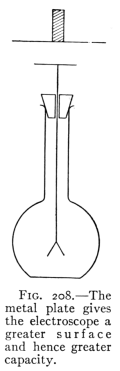 Fig. 208.—The metal plate provides the electroscope with a larger surface area, resulting in greater capacity.
230. Capacity.—If we have a 100-gallon tank and a 10-gallon tank connected by a pipe both filled with compressed air, the larger tank will contain ten times as much air as the smaller at the same pressure since it has ten times the capacity, or, if the two tanks are separated and the same amount of air is contained in each, the pressure of the air contained in the small tank will be ten times that in the large one.
230. Capacity.—If we have a 100-gallon tank and a 10-gallon tank connected by a pipe, both filled with compressed air, the larger tank will hold ten times as much air as the smaller one at the same pressure because it has ten times the capacity. Alternatively, if the two tanks are separated and each contains the same amount of air, the pressure in the small tank will be ten times that of the large tank.
The electrical capacity of a conductor is in some respects similar to the capacity of a tank for air. Since, however, electrical charges are upon the surface of a body, its capacity depends in part upon the extent of surface. For[Pg 260] example, if a charge is taken from a charged rubber rod by a proof plane to an electroscope a certain divergence of the leaves will be noticed. If a circular metal plate several times the diameter of the top of the electroscope is laid upon the latter (see Fig. 208), and a charge equal to that used before is brought to the electroscope, the leaves show less divergence than before, showing that the same charge gives a lower potential when placed upon a body of greater capacity.
The electrical capacity of a conductor is somewhat like the capacity of a tank for air. However, since electrical charges sit on the surface of an object, its capacity partially depends on the surface area. For[Pg 260] instance, if a charge is taken from a charged rubber rod using a proof plane to an electroscope, you'll notice a certain degree of leaf divergence. If you place a circular metal plate that is several times larger than the diameter of the top of the electroscope on it (see Fig. 208), and then bring a charge equal to the one used earlier to the electroscope, the leaves will show less divergence than before. This indicates that the same charge gives a lower potential when placed on a body with a greater capacity.
 Fig. 209.—A plate capacitor.
 Fig. 210.—A multi-plate condenser.
231. The electric condenser is a device having a large electrical capacity consisting of parallel conductors separated by good insulators. It has been devised to enable one to obtain a large electrical charge upon a body of convenient size. Such an apparatus is of great practical value in many experiments and operations. Its construction involves the principle of electrostatic induction in which a charge of one kind attracts and "holds" strongly a charge of opposite kind near it. In its simplest form it consists of two parallel conductors separated from each other (Fig. 209). The upper plate has been charged negatively. This has given the lower plate a positive charge by induction, since the latter is connected to the earth. These positive and negative charges hold or "bind" each other so that a large quantity may be accumulated. To increase the capacity of a condenser, several plates are used connected as in Fig. 210.
231. The electric condenser is a device with a high electrical capacity made up of parallel conductors separated by good insulators. It’s designed to allow a large electrical charge to be stored in a conveniently sized body. This apparatus is highly valuable for various experiments and operations. Its construction is based on the principle of electrostatic induction, where a charge of one type attracts and strongly "holds" a charge of the opposite type nearby. In its simplest form, it consists of two parallel conductors separated from each other (Fig. 209). The upper plate is negatively charged, which induces a positive charge on the lower plate since the latter is connected to the ground. These positive and negative charges "hold" each other, allowing a significant quantity to be stored. To increase the capacity of a condenser, multiple plates are used connected as shown in Fig. 210.
It is a curious fact that the kind of insulator between the[Pg 261] charged conductors of a condenser affects its capacity. Thus if glass, paraffine, or beeswax is between the plates instead of air, the plates will "hold" more electricity at the same potential. For this reason condenser plates are often separated by sheets of glass, paraffined paper, or mica.
It’s interesting to note that the type of insulator between the[Pg 261] charged conductors of a capacitor influences its capacity. So, if glass, paraffin, or beeswax is placed between the plates instead of air, the plates will "hold" more electricity at the same potential. Because of this, capacitor plates are often separated by sheets of glass, paraffin paper, or mica.
 Fig. 211.—A Leyden jar and a discharger.
232. The Leyden Jar.—A convenient form of condenser, used as long ago as 1745, is the Leyden jar. It consists of a glass jar (Fig. 211) coated part way up, inside and out, with tinfoil. The inner coating is connected by a chain to a knob at the top. The Leyden jar is charged by connecting the outer coating to the earth while to the inner coating is given a charge of either kind of electricity. The other kind of charge is developed by induction upon the outer coating, and each charge binds the other. To discharge a jar, a conductor, as a wire, is connected first to the outer coating and held there while the other end is brought to the knob at the top. A bright spark is produced when the two charges combine. It is best not to let the discharge from the jar pass through the body unless one is certain that only a very small charge is present.
232. The Leyden Jar.—A useful type of capacitor, the Leyden jar has been around since 1745. It consists of a glass jar (Fig. 211) that's partially coated inside and outside with tinfoil. The inner coating is connected by a chain to a knob at the top. You charge the Leyden jar by connecting the outer coating to the ground while applying a charge of either type of electricity to the inner coating. The opposite charge builds up on the outer coating due to induction, and both charges work together. To discharge the jar, you connect a conductor, like a wire, to the outer coating and hold it there while bringing the other end to the knob at the top. A bright spark occurs when the two charges meet. It's best to avoid letting the discharge from the jar pass through your body unless you're sure that only a very small charge is present.
233. Oscillatory Discharge.—The discharge from a Leyden jar is an interesting phenomenon. The rush of electricity from one coat to the other does not stop when the two coats are exactly neutralized but continues until the two plates are charged just oppositely to their condition at first, then a rush of electricity in the opposite direction occurs. This alternation continues several times and constitutes what is called the oscillatory discharge. (See Fig. 414.) This oscillatory discharge sets[Pg 262] up waves in the ether. These are called Hertzian waves in honor of their discoverer, Heinrich Hertz. They are the ether waves used in wireless telegraphy. A lightning flash has been shown by photographs and by other means to be oscillatory. This fact supports the idea that the electrical conditions just preceding the stroke of lightning reproduce a condenser on a large scale. The charged cloud is the upper charged plate, the earth beneath, charged by induction from the cloud, is the lower charged plate, while the air between is the insulator or dielectric as it is sometimes called.
233. Oscillatory Discharge.—The discharge from a Leyden jar is a fascinating phenomenon. The flow of electricity from one plate to the other doesn't stop when both plates reach a neutral state; it continues until the two plates are charged oppositely to their initial state, then a surge of electricity flows in the opposite direction. This back-and-forth continues several times and is known as the oscillatory discharge. (See Fig. 414.) This oscillatory discharge creates[Pg 262] waves in the ether. These waves are referred to as Hertzian waves, named after their discoverer, Heinrich Hertz. They are the ether waves used in wireless telegraphy. A lightning flash has been captured in photographs and other ways as being oscillatory. This supports the idea that the electrical conditions just before a lightning strike resemble those of a large-scale capacitor. The charged cloud acts as the upper charged plate, while the earth below, induced by the cloud's charge, serves as the lower charged plate, with the air in between acting as the insulator or dielectric, as it is sometimes called.
Important Topics
1. Potential: high, low, zero, positive, negative, similar to temperature and air pressure.
1. Potential: high, low, zero, positive, negative, similar to temperature and air pressure.
2. Capacity affected by (1) area, (2) induction.
2. Capacity influenced by (1) area, (2) induction.
3. Condensers, Leyden jar, parallel plate.
3. Capacitors, Leyden jar, parallel plates.
4. Oscillatory discharge, conditions, results.
4. Oscillating discharge, conditions, results.
Exercises
1. Is the air a conductor? Explain.
1. Is air a conductor? Explain.
2. Can the Leyden jar be strongly charged if the outer coat is insulated? Explain.
2. Can the Leyden jar be charged strongly if the outer layer is insulated? Explain.
3. Upon what two conditions does the capacity of a body depend? How in each case?
3. What two conditions affect a body's capacity? How does this apply in each situation?
4. Would a lightning discharge produce wireless waves? Explain.
4. Would a lightning strike create wireless waves? Explain.
5. If a sharp tack be dropped point up on the plate of an electroscope the latter is quickly discharged. Explain.
5. If a sharp tack is dropped point up on the plate of an electroscope, the electroscope quickly loses its charge. Explain.
(5) Static Electricity Generators
234. Static Electric Machines.—Many machines have been invented to produce larger quantities of static electricity than we have used in the experiments previously described. One of the earlier of these was the plate friction machine in which a large circular glass plate was rotated while a pad of some material was held against it. This machine was capable of producing powerful effects,[Pg 263] but it took much work to turn it, and it has been abandoned for a more efficient device, the static induction machine.
234. Static Electric Machines.—Many devices have been created to generate larger amounts of static electricity than what we've experienced in the previous experiments. One of the earlier models was the plate friction machine, which featured a large circular glass plate that was spun while a pad of material pressed against it. This machine could produce significant effects,[Pg 263] but it required a lot of effort to operate, and it has been replaced by a more efficient device, the static induction machine.
235. The electrophorus is the simplest static induction generator, consisting simply of a flat circular plate of some insulating material, as paraffine, shellac, or rosin contained in a metal pan, and a flat circular metal disc having an insulating handle.
235. The electrophorus is the simplest static induction generator, made up of a flat circular plate made from an insulating material like paraffin, shellac, or rosin that is held in a metal pan, along with a flat circular metal disc with an insulating handle.
 Fig. 212.—An electrophorus device.
The electrophorus is used as follows: The plate is first electrified by rubbing or beating with fur or a woolen cloth. The plate will be found to be charged negatively. The metal disc is placed upon the plate by holding the insulating handle. The upper surface of the charged body is slightly uneven so that the disc touches but a few high points. The greater part of the charged surface is separated from the metal disc by air, a good insulator. The charge therefore acts inductively upon the disc repelling negative electricity to the upper surface of the disc, leaving the lower surface charged positively (Fig. 212). If now the finger is touched to the disc the repelled negative charge escapes and the whole disc is left positively charged. The disc is now removed (Fig. 213) and the charge upon it may be tested or used in any desired manner. The disc may be recharged many times without rubbing the plate again.
The electrophorus is used as follows: First, the plate is charged by rubbing it with fur or a wool cloth. The plate will be negatively charged. The metal disc is then placed on the plate using the insulating handle. The top surface of the charged plate is slightly uneven, so the disc only makes contact at a few high points. Most of the charged surface is separated from the metal disc by air, which is a good insulator. The charge acts inductively on the disc, repelling negative electricity to the upper surface of the disc and leaving the lower surface positively charged (Fig. 212). If you touch the disc with your finger, the repelled negative charge will escape, leaving the whole disc positively charged. The disc can then be removed (Fig. 213), and the charge on it can be tested or used in any way desired. The disc can be recharged multiple times without needing to rub the plate again.
 Fig. 213.—Charged electrophorus.
These electrical charges possess energy. What is the[Pg 264] source of this energy? The answer may be determined by the following experiment. Place the disc upon the charged plate. Touch the disc with the finger to remove the repelled charge. Connect an electroscope to the disc by a fine wire. Nothing appears on the electroscope, since the disc has been connected to the earth, and is therefore at zero potential. If now the disc is lifted slowly, the leaves of the electroscope gradually separate, showing that a charge of electricity appears when the disc is being lifted against the force of attraction between the two charges. Just as potential energy is developed in a weight when it is lifted against the earth's attraction so electrical energy appears in the disc while it is being separated from the plate. The electrical energy of the charge is therefore due to the work done in separating the two charges. This electrical energy appears as heat and light, when the disc is discharged. It may be employed to ignite gas, gunpowder, etc.
These electrical charges have energy. What is the[Pg 264] source of this energy? We can find out through the following experiment. Place the disc on the charged plate. Touch the disc with your finger to remove the repelled charge. Connect an electroscope to the disc with a fine wire. Nothing shows up on the electroscope since the disc is grounded and therefore at zero potential. If you slowly lift the disc now, the leaves of the electroscope will gradually separate, indicating that a charge of electricity appears as the disc is lifted against the force of attraction between the two charges. Just like potential energy builds up in an object when it is lifted against the Earth's gravity, electrical energy is generated in the disc as it is separated from the plate. This electrical energy is a result of the work done in separating the two charges. When the disc is discharged, this electrical energy becomes heat and light. It can be used to ignite gas, gunpowder, and more.
236. The Toepler-Holtz Induction Machine.—This is a type of induction or influence machine that is often used for producing a continuous supply of electricity as in the operation of "X" ray machines, in lecture demonstrations, etc. This machine (Fig. 214) consists of two discs: one fixed, the other mounted so as to revolve. Upon the back of the fixed plate are two sectors of tinfoil which become charged oppositely. Upon the revolving plate are six metallic discs. These discs act like the discs of the electrophorus. They become charged by induction from the charges upon the sectors fastened to the fixed plate. The brushes held by a rod touch the discs at just the right time to take off the repelled charge. The charges induced upon the discs are taken off by two metal combs whose points are held close to the revolving disc. The Leyden jars assist in accumulating a good strong charge[Pg 265] before a spark passes between the terminal knobs. Some machines are built up of several pairs of plates and give correspondingly large amounts of electricity.
236. The Toepler-Holtz Induction Machine.—This is a type of induction or influence machine commonly used to produce a continuous supply of electricity, such as in "X" ray machines, lecture demonstrations, and more. This machine (Fig. 214) has two discs: one is fixed, while the other is mounted to rotate. On the back of the fixed plate are two sectors of tinfoil that become oppositely charged. The rotating plate has six metallic discs. These discs function like the discs of the electrophorus, getting charged through induction from the sectors attached to the fixed plate. Brushes held by a rod make contact with the discs at just the right moment to collect the repelled charge. The charges induced on the discs are removed by two metal combs that have their points held close to the rotating disc. The Leyden jars help accumulate a strong charge[Pg 265] before a spark jumps between the terminal knobs. Some machines consist of multiple pairs of plates, generating correspondingly larger amounts of electricity.
 Fig. 214.—The Toepler-Holtz induction motor.
Important Topics
Static Electric Generators.—(a) plate friction machine, (b) electrophorus, (c) induction or influence machine.
Static Electric Generators.—(a) plate friction machine, (b) electrophorus, (c) induction or influence machine.
Exercises
1. Potential is similar to what other terms that we have studied?
1. What other terms that we've studied are similar to potential?
2. What three electrical phenomena are better understood from a study of the lines of force?
2. What three electrical phenomena can we understand better by studying the lines of force?
3. How many charges may be produced by an electrophorus before the plate needs to be electrified again? Explain.
3. How many charges can an electrophorus produce before the plate needs to be charged again? Explain.
4. The static induction machine is often called a "continuous electrophorous." Why?
4. The static induction machine is often referred to as a "continuous electrophorous." Why?
5. The Leyden jars used with the induction machine cause much brighter sparks to be produced than without them. Explain.
5. The Leyden jars used with the induction machine create much brighter sparks than when they are not used. Explain.
6. With the Leyden jars removed, would the frequency with which the sparks pass between the knobs be increased or decreased? Explain.
6. With the Leyden jars taken out, would the frequency of sparks jumping between the knobs go up or down? Explain.
7. Mention three likenesses and three differences between magnetism and static electricity.
7. List three similarities and three differences between magnetism and static electricity.
8. Will you receive a greater shock by touching a knob of a charged Leyden jar when it is held in the hand or when it is standing on a sheet of glass? Explain.
8. Will you get a bigger shock by touching a knob of a charged Leyden jar when you're holding it in your hand or when it's sitting on a sheet of glass? Explain.
9. In what way may an electric charge be divided into three equal parts?
9. How can an electric charge be split into three equal parts?
Review Outline: Magnetism and Static Electricity
Comparison between Magnetism and Static Electricity.
Comparison between Magnetism and Static Electricity.
| Substances are: | magnetic, non-magnetic. | conductors, insulators. |
| Produced by: | induction. | friction, or induction. |
| Theory: | molecular. | electron. (fluid) |
| Fields of Force Explain: | attraction, repulsion, induction, action of compass. | attraction, repulsion, induction. |
| Terms: | magnetoscope, dip, declination, pole, retentivity, permeability, lodestone, magnetic meridian. | electroscope, electron, positive, negative, potential, capacity, condenser, electrophorus, oscillatory discharge, lightning. |
| Likeness: both are: | a—produced by induction, b—attract and repel, c—have fields of force. | |
| Differences: | a—electricity can be conducted, magnetism cannot. b—electricity in all substances, magnetism in few. c—magnetism with the compass indicates direction. | |
CHAPTER XI
CURRENT ELECTRICITY
CURRENT POWER
(1) Electric Currents and Circuits
237. Sources of Electric Currents.—In studying the production and distribution of static electricity it was seen that if two bodies at different potentials are connected by a copper wire a movement of electricity to the body having the lower potential occurred along the conducting wire. This movement of electricity is called an electric current (Art. 227). A difference of potential is therefore often called an electromotive force (E.M.F.), since it produces the movement of electricity in a conductor. The current between two oppositely charged bodies lasts for so short a time as to be of little or no practical value unless some means are found for continually recharging the bodies. That is, some device must be used to restore the difference in potential as fast as the conducting wire equalizes it. The continual charging of the bodies takes work. In other words, it requires a continual expenditure of some form of energy (which is converted into electrical energy) to produce the electric current. Two forms of energy are commonly used for this purpose.
237. Sources of Electric Currents.—When examining the creation and spread of static electricity, it was noted that when two objects at different potentials are linked by a copper wire, there is a flow of electricity to the object with the lower potential along the wire. This flow of electricity is known as an electric current (Art. 227). A difference in potential is often referred to as an electromotive force (E.M.F.), as it causes the flow of electricity in a conductor. The current between two oppositely charged objects lasts only for a brief moment and is generally not very useful unless a method is available to consistently recharge the objects. In other words, some device must be utilized to restore the difference in potential as quickly as the wire balances it out. Maintaining the charge on the objects requires effort. Essentially, it necessitates a continuous supply of some type of energy (which gets converted into electrical energy) to create the electric current. Two types of energy are typically used for this purpose.
(A) Chemical energy is employed in voltaic cells for producing electric currents. (B) Mechanical energy is used for the same purpose in the dynamo and similar devices.
(A) Chemical energy is used in voltaic cells to generate electric currents. (B) Mechanical energy serves the same function in the dynamo and similar devices.
238. The voltaic cell is named after Volta, an Italian physicist, who in 1800 invented it. In its simplest form it consists of a strip of copper and a strip of zinc placed in dilute sulphuric acid (one part acid to fifteen or twenty[Pg 268] of water) (Fig. 215). By the use of sensitive apparatus, it can be shown that the copper plate of the voltaic cell has a positive charge and the zinc plate a negative charge. For example, let a flat plate 10 cm. in diameter be placed upon the knob of an electroscope and a similar plate, coated with shellac and provided with an insulating handle, be set upon it to form a condenser. (See Fig. 216.) If now wires from the two plates of a simple voltaic cell be respectively connected to the plates of the condenser, charges from the copper and zinc plates will accumulate upon the two condenser plates. Now remove the wires and lift the upper plate. The "bound" charge upon the lower plate will spread over the leaves and cause them to separate. Upon testing, the charge from the zinc plate will be found to be negative and that from the copper plate, positive. Since a positive charge is found upon the copper plate it is called the positive electrode; the zinc plate is called the negative electrode.
238. The voltaic cell is named after Volta, an Italian physicist who invented it in 1800. In its simplest form, it consists of a copper strip and a zinc strip placed in diluted sulfuric acid (one part acid to fifteen or twenty[Pg 268] parts water) (Fig. 215). Using sensitive equipment, it can be demonstrated that the copper plate of the voltaic cell has a positive charge and the zinc plate has a negative charge. For instance, if you place a flat plate 10 cm in diameter on the knob of an electroscope and set a similar plate, coated with shellac and equipped with an insulating handle, on top of it to form a condenser (see Fig. 216), and then connect wires from the two plates of a simple voltaic cell to the plates of the condenser, charges from the copper and zinc plates will accumulate on the two condenser plates. Now, if you remove the wires and lift the upper plate, the "bound" charge on the lower plate will distribute over the leaves and cause them to separate. When tested, the charge from the zinc plate will be found to be negative, and that from the copper plate will be positive. Since the copper plate holds a positive charge, it is called the positive electrode; the zinc plate is referred to as the negative electrode.
 Fig. 215.—Cross-section of a basic voltaic cell.
Fig. 216.—Measuring the charges on the plates of a basic voltaic cell.
239. Test for an Electric Current.—If the copper and zinc plates of a voltaic cell are connected by a wire, a[Pg 269] current of electricity is set up in the conductor. Evidence of the current may be obtained by holding the conducting wire over and parallel to the needle of a magnetoscope. The needle is deflected by the action of the current parallel to it (Fig. 217). This magnetic effect of a current is the means usually employed for the detection and measurement of an electric current. Such a device which detects an electric current by its magnetic effect is called a galvanoscope, in honor of Galvani, who in 1786 was the first to discover how to produce an electric current.
239. Test for an Electric Current.—If the copper and zinc plates of a voltaic cell are connected by a wire, a[Pg 269] electric current flows through the conductor. You can see evidence of the current by holding the wire over and parallel to the needle of a magnetoscope. The needle gets deflected by the current flowing beside it (Fig. 217). This magnetic effect of a current is commonly used for the detection and measurement of an electric current. A device that detects an electric current by its magnetic effect is called a galvanoscope, named after Galvani, who was the first to discover how to produce an electric current in 1786.
 Fig. 217.—The magnetic needle is moved by the current.
 Fig. 218.—Diagram of an electric bell circuit.
240. The Electric Circuit.—The entire conducting path along which a current of electricity flows is called an electric circuit. In the case of a voltaic cell, the circuit includes not only the wires connecting the plates but also the plates themselves and the liquid between them. When some device or apparatus is to receive current from the cell, it is attached to the plates and wires so that the device is a part of the electric circuit. Separating the circuit at any point is called breaking or opening the circuit, while connecting the ends of an open circuit is called making or closing the circuit. A device for opening and closing a circuit is called a key or switch. The electric circuit used in ringing a door bell is familiar to most boys and girls. This circuit is open most of the time. It is closed by pressing the push-button at the door, and the flow of current through the electric bell causes the latter to ring. Such a circuit is represented in Fig. 218. Here C is the[Pg 270] voltaic cell, the two lines representing the plates of the cell. A cross-section view of the push-button (P), shows how the circuit is closed, (B) is the bell. Wherever current electricity is used the device in which it is employed forms a part of an electric circuit extending back to some electric generator. This generator must be able to continually produce an E.M.F., or a difference of potential between its terminals, in order that the movement of electricity may be continuous.
240. The Electric Circuit.—The complete path through which an electric current flows is known as an electric circuit. In a voltaic cell, the circuit includes not just the wires connecting the plates but also the plates themselves and the liquid in between. When a device or equipment needs electricity from the cell, it's connected to the plates and wires, making the device part of the electric circuit. Interrupting the circuit at any point is referred to as breaking or opening the circuit, while connecting the ends of an open circuit is called making or closing the circuit. A device for opening and closing a circuit is called a key or switch. Kids are usually familiar with the electric circuit that rings a doorbell. This circuit is open most of the time. It closes when you press the push-button at the door, and the current flowing through the electric bell causes it to ring. This circuit is illustrated in Fig. 218. Here C represents the[Pg 270] voltaic cell, with the two lines symbolizing the plates of the cell. A cross-section view of the push-button (P) shows how the circuit closes, and (B) represents the bell. Wherever electric current is used, the device that utilizes it is part of an electric circuit that connects back to some electric generator. This generator needs to constantly produce an E.M.F., or a difference in potential between its terminals, to ensure that the flow of electricity is continuous.
Important Topics
(a) Electric generators: (1) voltaic cell uses chemical energy; (2) dynamo uses mechanical energy.
(a) Electric generators: (1) a voltaic cell uses chemical energy; (2) a dynamo uses mechanical energy.
(b) Electric circuits: (1) open, (2) closed, (3) key and switch.
(b) Electric circuits: (1) open, (2) closed, (3) key and switch.
(c) Voltaic and galvanic electricity (names).
(c) Voltaic and galvanic electricity (names).
(d) Galvanoscope, uses.
(d) Galvanoscope uses.
Exercises
1. In what two ways are static and current electricity alike? In what two different?
1. In what two ways are static and current electricity similar? In what two ways are they different?
2. Draw a diagram of an electric bell circuit at your home. Give the location of the electric bell, the electric generator and the push-button. Show the connecting wires, and explain briefly how the circuit is operated.
2. Draw a diagram of the electric bell circuit in your home. Indicate where the electric bell, the electric generator, and the push-button are located. Show the connecting wires and briefly explain how the circuit works.
3. Represent some other electric circuit, naming the generator and other devices in the circuit.
3. Represent another electric circuit, naming the generator and other devices in the circuit.
4. Look up the work of Volta and Galvani and write a statement of the electrical discoveries and inventions made by them.
4. Research the work of Volta and Galvani and write a summary of the electrical discoveries and inventions they made.
(2) The Voltaic Cell and How It Works
241. The simple voltaic cell consists of a strip of copper and a strip of zinc placed in dilute sulphuric acid. (See Fig. 219.) A short time after placing the plates in the acid, bubbles of a gas (hydrogen) appear on the surface of the zinc. These bubbles increase in size and some rise to the surface of the liquid. Nothing appears upon the[Pg 271] copper plate. If the tops of the plates are connected by a wire, an electric current is set up through the wire and the cell, and bubbles of gas also appear upon the copper as well as on the zinc. In a short time the surface of the copper becomes coated with bubbles and the current becomes much weaker. If the plates are left in the acid for some time the zinc is found to be eaten away, having been dissolved in the acid through chemical action. The copper, however, remains practically unaffected.
241. The simple voltaic cell consists of a strip of copper and a strip of zinc placed in dilute sulfuric acid. (See Fig. 219.) Shortly after placing the plates in the acid, bubbles of gas (hydrogen) appear on the surface of the zinc. These bubbles grow larger, and some rise to the surface of the liquid. Nothing appears on the[Pg 271] copper plate. If the tops of the plates are connected by a wire, an electric current flows through the wire and the cell, and gas bubbles start to form on the copper as well as on the zinc. Soon, the surface of the copper is coated with bubbles, and the current becomes much weaker. If the plates are left in the acid for a while, the zinc is found to be worn away, having dissolved in the acid due to chemical action. The copper, however, remains practically unaffected.
 Fig. 219.—A basic battery.
242. How the Current is Produced.—To maintain the electric current a continual supply of energy is required. This is furnished by the chemical action of the acid upon the zinc. The chemical action is in several respects like combustion or burning, by means of which chemical energy is transformed into heat energy. In the voltaic cell the chemical action of the acid upon the zinc transforms chemical energy into electrical energy. The E.M.F. or difference of potential may be considered as originating at the surface of the zinc where the chemical action takes place. At this point the zinc has the lower and the liquid in contact with it the higher potential. The molecules of the acid are believed to be separated or broken up into two parts called ions; one ion, the SO4 or sulphion, combines with the zinc forming zinc sulphate, the other, or hydrogen (H) ion, passes over to the copper plate, and accumulates on the surface of this plate giving it a positive charge. It is therefore called the positive ion.[Pg 272] The sulphion ion, or SO4 ion, carries a negative charge to the zinc. It is therefore called the negative ion.
242. How the Current is Produced.—To keep the electric current flowing, a constant supply of energy is needed. This comes from the chemical action of the acid on the zinc. The chemical action is somewhat similar to combustion or burning, where chemical energy is converted into heat energy. In the voltaic cell, the chemical action of the acid on the zinc transforms chemical energy into electrical energy. The E.M.F. or difference of potential can be thought of as originating at the surface of the zinc where the chemical action occurs. At this point, the zinc has a lower potential, while the liquid in contact with it has a higher potential. The molecules of the acid are believed to split into two parts called ions; one ion, the SO4 or sulphion, combines with the zinc to form zinc sulphate, while the other, the hydrogen (H) ion, moves over to the copper plate and accumulates on its surface, giving it a positive charge. This is why it’s known as the positive ion.[Pg 272] The sulphion ion, or SO4 ion, carries a negative charge to the zinc, so it is called the negative ion.
243. The Direction of the Current.[K]—Beginning at the surface of the zinc the direction of the movement of positive electricity may be traced through the liquid to the copper plate, to the wire, to the zinc plate, to the starting point, thus completing the electric circuit. When the circuit is closed it is found that the movement of electricity starts in all parts of the circuit at practically the same instant.
243. The Direction of the Current.[K]—Starting at the surface of the zinc, the direction of positive electric movement can be traced through the liquid to the copper plate, then to the wire, and back to the zinc plate, returning to the starting point, thus completing the electric circuit. When the circuit is closed, it’s observed that the flow of electricity begins in all parts of the circuit at almost the same moment.
 Fig. 220.—A comparison of a voltaic cell and circuit with a water pump and connecting pipes.
244. The production of the current may be illustrated by describing a device for producing a continuous circulation of water. Thus let Cu and Zn represent two pipes connected by two horizontal tubes, one at V provided with a valve and one at P with a rotary Pump. (See Fig. 220.) Suppose the pipes filled to the level of V and the pump started. The pump will force water from Zn to Cu, through P, the level falling in Zn and rising in Cu. If the valve V is open the water will flow back through V as long as the pump is working. If V is closed, the level in Cu will rise as high as the driving force of the pump can send it. If now V is opened, the pump will maintain the water in circulation from Cu to Zn through V. In the illustration, the tubes Cu and Zn correspond to the conducting plates of copper and zinc of a voltaic cell. The pump P represents the chemical action which produces[Pg 273] the electrical pressure. The upper pipe represents the part of the circuit outside of the cell, the valve V corresponds to an electric key or switch which is used to open and close the electric circuit.
244. The production of the current can be explained by using a device that creates a continuous flow of water. Let Cu and Zn represent two pipes connected by two horizontal tubes, with one at V having a valve and the other at P featuring a rotary Pump. (See Fig. 220.) Assume the pipes are filled up to the level of V and the pump is turned on. The pump will push water from Zn to Cu through P, causing the level in Zn to drop and the level in Cu to rise. If the valve V is open, the water will flow back through V as long as the pump is running. If V is closed, the level in Cu will rise as high as the pump's driving force allows. If now V is opened, the pump will keep the water circulating from Cu to Zn through V. In this example, the pipes Cu and Zn are like the conducting plates made of copper and zinc in a voltaic cell. The pump P represents the chemical reaction that generates[Pg 273] the electrical pressure. The upper pipe is the part of the circuit outside the cell, and the valve V acts like an electric key or switch used to open and close the electric circuit.
245. Polarization.—In the simple voltaic cell, after the circuit is closed, bubbles of hydrogen collect upon the copper plate. This accumulation of hydrogen gas is called polarization. It acts as a non-conducting layer upon the surface of the plate and seriously interferes with the movement of electricity from the liquid to the copper plate not only in the simple voltaic cell but in many others as well. Some voltaic cells are made entirely free from this defect, either (a) by the removal of the hydrogen as fast as it is formed, or (b) by the use of such chemicals that no hydrogen is produced.
245. Polarization.—In a basic voltaic cell, once the circuit is closed, hydrogen bubbles build up on the copper plate. This buildup of hydrogen gas is known as polarization. It creates a non-conductive layer on the surface of the plate, which significantly disrupts the flow of electricity from the liquid to the copper plate, not just in this simple voltaic cell but in many others as well. Some voltaic cells are designed to eliminate this issue completely, either (a) by removing the hydrogen as quickly as it forms, or (b) by using chemicals that prevent hydrogen from being produced.
246. Local Action.—It is noticed that when a strip of zinc is placed in dilute acid that bubbles appear upon the surface of the zinc. The appearance of these bubbles indicates that some of the hydrogen ions carrying positive electricity have moved to the zinc plate. Careful examination of the plate after it has been in acid shows numerous black spots upon it. These are bits of carbon. They are always found in ordinary zinc. Small electric currents are set up which run from molecules of pure zinc into the liquid and back to the carbon particles, thus forming small closed circuits. (See Fig. 221.) The formation of these circuits from and to the zinc is called local action. This action is a defect in voltaic cells since a part of the current is thus kept from passing through the main outside circuit, and the zinc may be consumed even when no outside current is flowing.
246. Local Action.—When a strip of zinc is placed in dilute acid, bubbles form on the surface of the zinc. These bubbles indicate that some of the hydrogen ions, which carry positive charge, have moved to the zinc plate. A close look at the plate after it has been in the acid reveals numerous black spots on it. These are bits of carbon, which are always present in regular zinc. Small electric currents are generated that flow from pure zinc molecules into the liquid and back to the carbon particles, creating tiny closed circuits. (See Fig. 221.) The creation of these circuits involving the zinc is called local action. This action is a flaw in voltaic cells because it prevents part of the current from flowing through the main external circuit, and the zinc can be consumed even when no external current is active.
 Fig. 221.—Local activity.
247. Amalgamation.—Local action is prevented by coating the zinc with mercury. This process is called amalgamation. The mercury covers the entire surface of the[Pg 274] plate in the acid. Its action is to dissolve pure zinc and bring it to the outer surface where it is acted upon by the acid. The carbon particles are kept covered so that no local currents can be formed as long as the bits of carbon are below the surface. Amalgamation therefore prevents local action.
247. Amalgamation.—Local action is stopped by covering the zinc with mercury. This process is known as amalgamation. The mercury coats the entire surface of the [Pg 274] plate in the acid. It works by dissolving pure zinc and bringing it to the outer surface where the acid acts on it. The carbon particles remain covered so that no local currents can form as long as the carbon pieces are beneath the surface. Therefore, amalgamation prevents local action.
Important Topics
The Simple Voltaic Cell
The Basic Voltaic Cell
1. Two plates: zinc, copper; electrolyte, dilute sulphuric acid.
1. Two plates: zinc, copper; electrolyte, diluted sulfuric acid.
2. Ions: hydrogen, positive: sulphion, negative.
2. Ions: hydrogen, positive: sulfate ion, negative.
3. Current, where and how produced, direction, illustration.
3. Current, where it’s produced, how it’s made, direction, illustration.
4. Polarization: cure, local action, cure.
4. Polarization: fix, local action, fix.
Exercises
1. Write in your own words an account of the production of an electric current by the simple voltaic cell. Use sketches.
1. Describe in your own words how an electric current is generated by a basic voltaic cell. Include sketches.
2. Which plate has the higher potential? How is it produced?
2. Which plate has more potential? How is it created?
3. Would you expect to get an E.M.F. by forming a cell of two copper plates? Why?
3. Do you think you would get an E.M.F. by creating a cell with two copper plates? Why?
(3) Practical Battery Cells
248. Advantages of Voltaic Cells.—Many forms of voltaic cells have been devised. Several of the more common of these will be described and their electro-chemical action explained.
248. Advantages of Voltaic Cells.—Many types of voltaic cells have been created. Some of the more common ones will be described, and their electro-chemical action will be explained.
At the present time voltaic cells are employed only where small currents are needed, such as for electric bells and induction coils. Where more than a small amount of current is required, the dynamo and the storage battery have generally taken their place as sources of electric current.
At present, voltaic cells are used only in situations where small currents are needed, like for electric bells and induction coils. When a larger amount of current is required, dynamos and storage batteries usually serve as the sources of electrical current.
The advantages of voltaic cells as electric generators are: (a) they are inexpensive, (b) they are easily taken from place to place, (c) they may be ready for instant use.
The benefits of voltaic cells as electric generators are: (a) they are affordable, (b) they can be easily transported, (c) they can be ready for immediate use.
The most desirable voltaic cell would be one having the[Pg 275] following qualities: (a) High electromotive force, (b) no polarization or local action, (c) very low internal resistance, (d) small expense, both as to first cost and upkeep.
The ideal voltaic cell would have the[Pg 275] following characteristics: (a) High electromotive force, (b) no polarization or local action, (c) very low internal resistance, (d) low cost, both for initial investment and maintenance.
 Fig. 222.—The Leclanché cell, "wet" version.
249. The Leclanché cell is the one commonly used for ringing door bells. It has two plates: one of zinc and the other of carbon. These are placed in a solution of sal ammoniac (Fig. 222). Take up the desirable qualities mentioned at the end of the preceding paragraph. (a) It may be shown that this cell has a good E.M.F. about 1.5 volts. (b) It polarizes easily yet it recovers well when left upon open circuit. Usually a substance called manganese dioxide is mixed with the carbon. This acts as a depolarizer, that is, it combines with the hydrogen to form water. (c) Its resistance varies and is often considerable. (d) The expense for upkeep is small, since a 5-cent rod of zinc, and a 5-cent charge of sal ammoniac will keep the cell in action on a bell circuit from six months to a year or more. It is well suited for use on open circuits that is, where the circuit is open the greater part of the time and is closed only occasionally; as in ringing door bells, operating telephones, and other devices whose circuits are usually open.
249. The Leclanché cell is the type typically used for ringing doorbells. It has two plates: one made of zinc and the other made of carbon. These are placed in a solution of ammonium chloride (Fig. 222). Take note of the desired qualities mentioned at the end of the previous paragraph. (a) It can be demonstrated that this cell has a good E.M.F. of about 1.5 volts. (b) It polarizes easily but recovers well when left on an open circuit. Usually, a substance called manganese dioxide is mixed with the carbon. This acts as a depolarizer, meaning it combines with the hydrogen to form water. (c) Its resistance varies and can often be considerable. (d) The maintenance cost is low, since a 5-cent zinc rod and a 5-cent charge of ammonium chloride will keep the cell operational in a bell circuit for six months to a year or more. It is well suited for use on open circuits, where the circuit is open most of the time and closed only occasionally, like in ringing doorbells, operating telephones, and other devices whose circuits are usually open.
250. The Dry Cell.—Many forms of Leclanché cells are made. One of these is called the dry cell (See Fig. 223.) In this cell the zinc plate is made into a jar or can and contains the other materials. At the center of the cell is a rod of carbon and manganese dioxide. The space between the carbon and zinc is filled with a porous material such as sawdust or plaster of Paris. A strong solution of sal ammoniac fills the porous material. The[Pg 276] top of the cell is sealed with pitch or wax to prevent evaporation. The great advantage of this cell is that it may be used or carried in any position without danger of spilling its contents. Dry cells are often used to operate the spark coils of gas and gasoline engines. The Leclanché cell described in Art. 249 is commonly known as the "wet cell."
250. The Dry Cell.—There are many types of Leclanché cells. One of them is called the dry cell (See Fig. 223.) In this cell, the zinc plate forms a jar or can that holds the other materials. At the center of the cell is a rod made of carbon and manganese dioxide. The space between the carbon and zinc is filled with a porous material like sawdust or plaster of Paris. A strong solution of sal ammoniac fills the porous material. The[Pg 276] top of the cell is sealed with pitch or wax to prevent evaporation. The main advantage of this cell is that it can be used or carried in any position without risking spills. Dry cells are often used to power the spark coils of gas and gasoline engines. The Leclanché cell described in Art. 249 is commonly known as the "wet cell."
 Fig. 223.—The Leclanché cell, "dry" version.
 Fig. 224.—The Daniell battery.
251. The Daniell Cell.—This cell is often used in laboratories, and on closed circuits such as those connected with fire and burglar alarms and telegraph lines. It has two plates of zinc and copper placed in two different liquids which are kept separated by a porous clay cup (Fig. 224). The zinc rod is kept in a solution of zinc sulphate contained in the porous cup. The copper plate is in a solution of copper sulphate filling the rest of the glass jar. Unlike the Leclanché cell, this one must be kept upon a closed circuit to do its best work, as the two liquids mix when the circuit is open. Taking its qualities in order, (a) its E.M.F. is about one volt, (b) it has no polarization since copper instead of hydrogen is deposited upon the copper plate. Therefore a uniform E.M.F. may be obtained from it, making it especially useful in laboratory experiments and tests. (c) Its resistance is considerable and (d) it is more expensive to operate than the Leclanché. It is sometimes used upon closed circuits outside of laboratories[Pg 277] as in burglar and fire alarms, although in recent years, the storage battery is taking its place for these purposes.
251. The Daniell Cell.—This cell is commonly used in laboratories and in closed circuits like those for fire and burglar alarms and telegraph lines. It consists of two plates, zinc and copper, placed in two different liquids that are separated by a porous clay cup (Fig. 224). The zinc rod is kept in a zinc sulfate solution within the porous cup, while the copper plate is immersed in a copper sulfate solution that fills the rest of the glass jar. Unlike the Leclanché cell, this one needs to be on a closed circuit to work properly since the two liquids will mix when the circuit is open. Considering its features: (a) it has an E.M.F. of about one volt, (b) there is no polarization because copper is deposited on the copper plate instead of hydrogen. This results in a consistent E.M.F., making it particularly useful for laboratory experiments and tests. (c) Its resistance is significant, and (d) it's more costly to operate than the Leclanché. It is sometimes used in closed circuits outside of laboratories, like in burglar and fire alarms, although in recent years, the storage battery has been replacing it for these applications.
252. The Gravity Cell.—Fig. 225 is like the Daniell cell in most respects, except that in this cell, the zinc plate is held at the top of the jar in a solution of zinc sulphate while the copper plate is at the bottom, surrounded by a solution of copper sulphate. The solutions mix but slowly as the copper sulphate solution is denser and remains at the bottom. This cell like the Daniell must also be kept upon closed circuit. On account of its simplicity and economy it is often used to operate telegraph instruments. Its qualities are similar to those of the Daniell cell.
252. The Gravity Cell.—Fig. 225 is similar to the Daniell cell in most ways, except that in this cell, the zinc plate is positioned at the top of the jar in a zinc sulfate solution while the copper plate is at the bottom, surrounded by a copper sulfate solution. The solutions mix slowly because the copper sulfate solution is denser and stays at the bottom. Like the Daniell cell, this one must also be kept on a closed circuit. Because of its simplicity and cost-effectiveness, it is often used to power telegraph devices. Its characteristics are comparable to those of the Daniell cell.
 Fig. 225.—The gravity battery.
253. Symbol for Voltaic Cells.—In electrical diagrams, the symbol employed to represent a voltaic cell is a short thick line near to and parallel to a longer thin one. As in Fig. 226. If several cells are to be represented the conventional symbol of the combination is represented as in Fig. 227. A single cell and a group of cells are each frequently called a battery.
253. Symbol for Voltaic Cells.—In electrical diagrams, the symbol used to represent a voltaic cell is a short, thick line positioned close to and parallel to a longer, thin line, as shown in Fig. 226. When multiple cells are shown, the standard symbol for the combination is depicted as in Fig. 227. A single cell and a group of cells are often referred to as a battery.
 Fig. 226.—Illustration of a single cell.
Fig. 227.—Illustration of a group of cells.
254. Effects of Electric Currents.—Having studied some of the devices for producing an electric current, let[Pg 278] us now consider some of the effects caused by it. These effects will be studied under three heads: (a) Magnetic, (b) Chemical, and (c) Heat effects. Devices or articles showing these effects known to most high school students are respectively: (a) the electromagnet (b) electro-plated silver ware and (c) electric heaters, such as electric flat irons, electric toasters, etc. The magnetic effect of an electric current was first detected by Oersted at the University of Copenhagen in 1819. It may be observed by holding a wire carrying a current from a voltaic cell above and parallel to the needle of a magnetoscope. The needle is at once deflected (Fig. 228). If the current is reversed in direction the magnetoscope needle is deflected in the reverse direction. This simple device is the most common means for detecting an electric current. It therefore constitutes a galvanoscope. (See Art. 239.)
254. Effects of Electric Currents.—Now that we’ve looked at some ways to generate an electric current, let[Pg 278]’s explore some of the effects it produces. We’ll examine these effects under three categories: (a) Magnetic, (b) Chemical, and (c) Heat. Devices or items demonstrating these effects, which are familiar to most high school students, include: (a) the electromagnet, (b) electroplated silverware, and (c) electric heaters, like electric irons and toasters. The magnetic effect of an electric current was first discovered by Oersted at the University of Copenhagen in 1819. You can see this effect by holding a wire that carries current from a battery above and parallel to the needle of a magnetoscope. The needle will immediately shift (Fig. 228). If the current’s direction is reversed, the magnetoscope needle moves in the opposite direction. This simple device is the most common way to detect an electric current. It is therefore known as a galvanoscope. (See Art. 239.)
 Fig. 227.—Diagram of a cluster of cells.Fig. 228.—A galvanoscope.
Important Topics
1. Leclanché cells, (a), wet, (b), dry, construction, advantages, uses.
1. Leclanché cells: (a) wet, (b) dry, construction, advantages, uses.
2. Daniell and gravity cells, construction, advantages, uses.
2. Daniell and gravity cells: construction, advantages, and applications.
3. Three effects of electric currents, illustrations.
3. Three effects of electric currents, illustrations.
4. The galvanoscope, uses.
4. The galvanoscope is used.
Exercises
1. Explain how the direction of current in a wire can be determined by a compass.
1. Explain how a compass can be used to figure out the direction of current in a wire.
2. Would you expect to obtain a current from a zinc and copper cell containing a solution of common salt? Perform the experiment.
2. Would you expect to get a current from a zinc and copper cell with a common salt solution? Run the experiment.
3. What conditions in a voltaic cell will give a steady electromotive force.
3. What conditions in a voltaic cell will produce a steady electromotive force?
4. What conditions in a voltaic cell will give a strong electromotive force.
4. What conditions in a voltaic cell will create a strong electromotive force?
5. Name three different electric circuits that you know exist. Which are open and which are closed circuits?
5. Name three different electric circuits that you know of. Which are open and which are closed circuits?
6. Are voltaic cells used in your home? If so, for what purpose are they used? On open or closed circuits? Have you seen them? what kind are they?
6. Are there batteries used in your home? If yes, what are they used for? In open or closed circuits? Have you seen them? What type are they?
CHAPTER XII
THE MAGNETIC EFFECT OF ELECTRIC CURRENTS. ELECTRICAL MEASUREMENTS
THE MAGNETIC EFFECT OF ELECTRIC CURRENTS. ELECTRICAL MEASUREMENTS
(1) The Magnetic Effect of Electric Currents
255. The Magnetic Effect.—Of all the effects of electric currents, it is generally conceded that the magnetic effect is the one of greatest practical importance, and it is also the one most extensively used. An experiment illustrating this effect has been described in Art. 239. This experiment shows that an electric current, if parallel to a magnetic needle, and near it will deflect the north-seeking pole of the needle to the right or left depending upon the direction of the current flow. This deflection of the magnetic needle is due to the fact that surrounding every electric current are magnetic lines of force. It is this magnetic field of the current that causes the needle to turn. The position taken by the needle is the resultant of the forces of two magnetic fields; one, the earth's field, the other, that of the current.
255. The Magnetic Effect.—Of all the effects of electric currents, it's widely recognized that the magnetic effect is the one of greatest practical importance, and it's also the one that's used most extensively. An experiment demonstrating this effect was described in Art. 239. This experiment shows that an electric current, if parallel to a magnetic needle and close to it, will deflect the north-seeking pole of the needle to the right or left depending on the direction of the current flow. This deflection of the magnetic needle happens because every electric current is surrounded by magnetic lines of force. It's this magnetic field from the current that makes the needle turn. The position of the needle is the result of the forces from two magnetic fields; one from the Earth's field and the other from the current.
256. Right-hand Rule for a Conductor.—To show the presence of the magnetic field about a current, pass a thick copper wire vertically through a sheet of paper, and connect the ends of the wire to a source of current. While the current (this should be as much as 10 amperes if possible) is flowing, sprinkle iron filings upon the paper and tap gently. The filings will arrange themselves in circles about the wire showing the magnetic field. (See Fig. 229.) The needle of a magnetoscope tends to place itself parallel to the lines of force of this field and from this action or[Pg 280] tendency the direction of the magnetic lines about a current may be determined. The following rule is helpful and should be memorized: Grasp the conductor with the right hand with the outstretched thumb in the direction that the current is flowing. The fingers will then encircle the wire in the direction of the lines of force. This rule may be reversed, for, if the fingers of the right hand grasp the wire so as to point with the magnetic field, then the current flows in the direction in which the thumb points. (See Fig. 230.)
256. Right-hand Rule for a Conductor.—To demonstrate the presence of the magnetic field around a current, push a thick copper wire vertically through a sheet of paper and connect the ends of the wire to a current source. While the current (ideally around 10 amperes) is flowing, sprinkle iron filings on the paper and tap it gently. The filings will arrange themselves in circles around the wire, indicating the magnetic field. (See Fig. 229.) The needle of a magnetoscope tends to align itself parallel to the lines of force of this field, and from this behavior, the direction of the magnetic lines around a current can be determined. The following rule is useful and should be memorized: Grasp the conductor with your right hand, with your outstretched thumb pointing in the direction of the current flow. Your fingers will then wrap around the wire in the direction of the lines of force. This rule can also be reversed; if you grasp the wire with your right hand so that your fingers point along the magnetic field, then the current flows in the direction your thumb points. (See Fig. 230.)
 Fig. 229.—Magnetic field around a wire that carries an electric current.
Fig. 230.—Right-hand rule for the magnetic field created by a current.
257. Magnetic Field of a Helix.—If a wire be wound about a cylinder to form a cylindrical coil with parallel turns, it forms a helix or solenoid. The shape of the magnetic field about a current depends upon the form of the conductor. If the latter is in the form of a helix its magnetic field resembles that of a straight bar magnet. (See Fig. 231). In fact the helix has the properties of a magnet with north- and south-seeking poles while a current is flowing through it. If such a coil is suspended so as to turn freely, it tends to turn until the field within it is parallel to the earth's magnetic field. Such a suspended helix may therefore be used as a compass. In order to strengthen the magnetic field of a helix or solenoid, the space within its turns is filled with iron, often in the form[Pg 281] of small soft-iron wires. This bundle of iron wire is called the core of the helix. The core becomes strongly magnetized by the field of the helix while the current is flowing and quickly loses its magnetic force when the current is stopped. The direction of the current in a helix (Fig. 232) or the polarity of its core may be determined by another right-hand rule. If the helix is grasped with the right hand so that the fingers point in the direction in which the current is flowing, the extended thumb will point in the direction of the north pole of the helix. On the other hand, if the poles of the helix are known, then, when the helix is grasped with the right hand so that the thumb points to the north-seeking pole, the current is flowing in the wires in the direction that the fingers point.
257. Magnetic Field of a Helix.—If a wire is wound around a cylinder to create a cylindrical coil with parallel turns, it forms a helix or solenoid. The shape of the magnetic field around a current depends on the form of the conductor. When the conductor is shaped like a helix, its magnetic field resembles that of a straight bar magnet. (See Fig. 231). In fact, the helix has the properties of a magnet with north and south poles while a current is flowing through it. If this coil is suspended in a way that allows it to turn freely, it will align itself so that the field inside it is parallel to the Earth's magnetic field. This suspended helix can therefore function as a compass. To enhance the magnetic field of a helix or solenoid, the space within its turns is filled with iron, often in the form[Pg 281] of small soft-iron wires. This collection of iron wire is called the core of the helix. The core becomes strongly magnetized by the helix's field while the current is flowing and quickly loses its magnetism when the current stops. The direction of the current in a helix (Fig. 232) or the polarity of its core can be determined using another right-hand rule. If you grasp the helix with your right hand so that your fingers point in the direction the current flows, your extended thumb will point toward the north pole of the helix. Conversely, if the poles of the helix are known, when you hold the helix with your right hand so that your thumb points to the north pole, the current flows in the direction that your fingers point.
 Fig. 231.—The magnetic field of a helix.
Fig. 232.—Right-hand rule for a helix.
258. The Electromagnet.—These "right-hand" rules are applied in many different devices. Among these, perhaps the most important is the electromagnet, which is used in the electric bell, the telegraph, the telephone, the dynamo, the motor, and many other electric contrivances.
258. The Electromagnet.—These "right-hand" rules are used in many different devices. Among these, maybe the most important is the electromagnet, which is found in the electric bell, the telegraph, the telephone, the dynamo, the motor, and many other electric gadgets.
The electromagnet is defined as a mass of iron around which is placed a helix for conducting an electric current. On account of its large permeability, the iron core of the helix adds greatly to the effectiveness of the electromagnet, since the magnetism of the iron is added to that of the current in the helix. The magnetism remaining[Pg 282] in the iron after the current stops is called the residual magnetism. The residual magnetism is small when the core is made of small wires or thin plates, but is larger when the iron core is solid. Like artificial steel magnets, electromagnets are usually of two forms, bar and horseshoe. (See Figs. 233 and 234.) For most purposes the horseshoe form is the more effective since it permits a complete iron circuit for the magnetic lines of force. (See Fig. 235.) This is the form used in the electric bell, in the telegraph sounder, and in lifting magnets. (See Fig. 236.)
The electromagnet is defined as a mass of iron around which a coil is placed to conduct an electric current. Due to its high permeability, the iron core of the coil significantly enhances the effectiveness of the electromagnet, since the magnetism of the iron combines with that of the current in the coil. The magnetism that remains[Pg 282] in the iron once the current stops is known as residual magnetism. The residual magnetism is minimal when the core is made of small wires or thin plates, but is greater when the iron core is solid. Similar to artificial steel magnets, electromagnets typically come in two shapes: bar and horseshoe. (See Figs. 233 and 234.) For most applications, the horseshoe shape is more effective because it allows for a complete iron circuit for the magnetic lines of force. (See Fig. 235.) This is the design used in electric bells, telegraph sounders, and lifting magnets. (See Fig. 236.)
 Fig. 233.—A bar electromagnet.
Fig. 234.—A horseshoe electromagnet.
 Fig. 235.—A horseshoe electromagnet can have a full iron circuit for its magnetic lines of force.
Fig. 236.—A lifting magnet.
259. Effective Electromagnets.—The magnetic effect of a current in a helix is small, hence the force usually is increased by inserting a core of iron. When at first man[Pg 283] tried to signal with electromagnets at a distance it was found that the current would not work the electromagnet. An American by the name of Joseph Henry discovered the remedy for this condition. He found that if the copper wire was insulated by wrapping silk thread about it, and then many layers of the silk insulated wire were wound upon a spool with an iron core, that the magnet would work at a great distance from the source of current. If the current is increased, the magnet is stronger than at first. Thus an electromagnet may be made stronger by (a) increasing the number of turns of wire in its coils and by (b) sending a stronger current through it.
259. Effective Electromagnets.—The magnetic effect of a current in a coil is small, so the force is usually enhanced by adding an iron core. Initially, when people tried to signal over distances using electromagnets, they found that the current couldn’t activate the electromagnet. An American named Joseph Henry discovered a solution to this problem. He found that if the copper wire was insulated by wrapping silk thread around it, and then multiple layers of this silk-insulated wire were wound onto a spool with an iron core, the magnet could be activated from a long distance away. Increasing the current makes the magnet even stronger than before. Therefore, an electromagnet can be made stronger by (a) increasing the number of turns of wire in its coils and (b) sending a stronger current through it.
 Fig. 237.—A basic telegraph circuit.
260. The Telegraph.—The invention of an effective electromagnet by Henry made possible the electric telegraph. In its simplest form it consists of a battery, C, a key, K, and a sounder, S, with connecting wires. (See Fig. 237.) The sounder (Fig. 238) contains a horseshoe electromagnet and a bar of soft iron across its poles called an armature, A, attached to a lever L. When the key is closed, the electromagnet draws down the armature and lever until the latter hits a stop O, making a click. When the key is raised, the magnet releases the armature which is raised by the action of a spring at S until the lever hits a stop at T making another click. Closing and opening the circuit at K will start and stop the current which operates S which may be 100 miles or more from K. One voltaic cell will work a sounder in the same room. But if many miles of wire are in the circuit, the E.M.F. of a single cell will not force sufficient current through the long wire to operate the sounder.
260. The Telegraph.—The invention of an effective electromagnet by Henry made the electric telegraph possible. At its most basic, it includes a battery, C, a key, K, and a sounder, S, connected by wires. (See Fig. 237.) The sounder (Fig. 238) has a horseshoe electromagnet and a bar of soft iron across its poles called an armature, A, which is attached to a lever L. When the key is pressed, the electromagnet pulls down the armature and lever until the lever hits a stop O, creating a click. When the key is released, the magnet lets go of the armature, which is lifted by a spring at S until the lever hits a stop at T, producing another click. Closing and opening the circuit at K starts and stops the current that powers S, which can be 100 miles or more away from K. One voltaic cell can operate a sounder in the same room. However, if there are many miles of wire in the circuit, the E.M.F. of a single cell won’t push enough current through the long wire to operate the sounder.
 Fig. 238.—A telegraph buzzer.
 Fig. 239.—A telegraph relay.
Fig. 240.—How the relay is utilized.
 Samuel F. B. Morse (1791-1872)
Inventor of the electromagnetic recording telegraph and the dot and dash alphabet.
Samuel F. B. Morse (1791-1872)
Inventor of the electromagnetic recording telegraph and the dot and dash alphabet.Samuel F. B. Morse
"From Appleton's Cyclopedia of American Biography, Copyright 1888 by D. Appleton & Co."
 Thomas A. Edison, Orange, New Jersey. He invented the incandescent lamp, phonograph, and moving picture, and is recognized as the most notable inventor of modern electrical appliances.
Thomas A. Edison
"Copyright, Photographische Gessellschaft," and "By Permission of the Berlin Photographic Co., New York."
A battery of several cells is then required. Even a
large battery is insufficient to operate a long line containing
many sounders in circuit. Recourse is therefore usually
made to a more sensitive
device called a
relay. (See Fig. 239.)
In the relay a very
small current will magnetize
its electromagnet
enough to draw
toward it the delicately
hung armature
thereby closing a second
circuit which contains a sounder and a battery. (See
Fig. 240.) when the current in the main circuit is
stopped, the armature of the relay is drawn back by a light
spring. This opens the local circuit. Thus the local circuit
is closed and opened by the relay just in time with
the starting and stopping of the current in the main line.
It is thus possible for a small current in the main line by
the use of a relay, to close and open a second local circuit[Pg 285]
[Pg 286]
[Pg 287]
containing a local battery and sounder. Modern telegraph
lines are operated in this manner.
A battery made up of several cells is needed. Even a large battery isn't enough to power a long circuit with many sounders. That's why we usually use a more sensitive device called a relay. (See Fig. 239.) In the relay, a very small current can magnetize its electromagnet enough to pull the delicately suspended armature, which closes a second circuit that has a sounder and a battery. (See Fig. 240.) When the current in the main circuit stops, a light spring pulls the armature of the relay back, opening the local circuit. This means the local circuit is closed and opened by the relay just as the current in the main line starts and stops. This allows a small current in the main line to control a second local circuit[Pg 285]
[Pg 286]
[Pg 287] with a local battery and sounder. Modern telegraph lines work this way.
 Fig. 241.—An electric bell and its circuit.
261. The electric bell (see Fig. 241), consists of an electromagnet, M, a soft iron armature, A, attached to the tapper, T, and a post, R. When no current is flowing a spring at S holds the armature against the post R. When current flows through the helix, its core becomes magnetized and attracts the armature, drawing it away from the post, R, and causing the tapper to hit the bell. Drawing A away from the post, however, breaks the circuit at R and the current stops. The magnetism in the core disappears releasing the armature, which is then pulled back by the spring S against the post R. This completes the circuit and the process repeats itself several times a second as long as the current flows.
261. The electric bell (see Fig. 241) consists of an electromagnet, M, a soft iron armature, A, attached to the tapper, T, and a post, R. When no current is flowing, a spring at S keeps the armature pressed against the post R. When current flows through the coil, its core gets magnetized and pulls the armature away from the post R, making the tapper hit the bell. Pulling A away from the post, however, breaks the circuit at R and stops the current. The magnetism in the core fades, allowing the armature to be returned by the spring S against the post R. This completes the circuit, and the process repeats itself several times a second as long as the current flows.
 Fig. 242.—Magnetizing using the discharge from a Leyden jar.
262. Static and Current Electricity Compared.—The likeness between a discharge of static electricity and an electric current may be shown by winding a coil of insulated wire about a glass tube which contains a steel needle. If a Leyden jar (see Fig. 242) is discharged through the coil the steel needle is usually found to be magnetized, showing that the discharge of the static electricity has a magnetic effect similar to that of an electric current. Sometimes a given end of the needle has a north pole and at other times a south pole. This is believed to indicate[Pg 288] that the charge of the Leyden jar is oscillatory, and that in different discharges sometimes a surge in one direction and at other times a surge in the reverse direction has been most effective in magnetizing the needle. Compare this action with that described in Art. 233.
262. Static and Current Electricity Compared.—The similarity between a static electricity discharge and an electric current can be demonstrated by wrapping a coil of insulated wire around a glass tube that has a steel needle inside. When a Leyden jar (see Fig. 242) is discharged through the coil, the steel needle is usually found to be magnetized, indicating that the static electricity discharge has a magnetic effect similar to that of an electric current. Sometimes one end of the needle acts as a north pole, while at other times it acts as a south pole. This is thought to suggest[Pg 288] that the charge of the Leyden jar is oscillatory, meaning that in different discharges, there is sometimes a surge in one direction and at other times a surge in the opposite direction that has been most effective in magnetizing the needle. Compare this action with what is described in Art. 233.
Important Topics
1. Right-hand rules, for conductor, for helix.
1. Right-hand rules for conductors and for helices.
2. The electromagnet, two forms, where used?
2. The electromagnet, two types, where was it used?
3. Likeness between static and current electricity.
3. Similarities between static and current electricity.
4. The electric bell, parts, action.
4. The electric bell: components and operation.
5. The telegraph, key, sounder, relay.
5. The telegraph, key, sounder, relay.
Exercises
1. What is the difference between an electric charge and a current?
1. What’s the difference between an electric charge and a current?
2. How can a magnetic effect be produced from an electric charge?
2. How can an electric charge create a magnetic effect?
3. What is a magnetic field? Give two evidences of a magnetic field about a current in a wire?
3. What is a magnetic field? Provide two pieces of evidence of a magnetic field caused by an electric current in a wire.
4. A current is flowing north in trolley wire, what is the direction of the magnetic field under the wire? Explain.
4. A current is flowing north in the trolley wire. What is the direction of the magnetic field underneath the wire? Explain.
5. What would be the result if a hard steel core were placed in the electromagnet? Explain.
5. What would happen if a hard steel core were inserted into the electromagnet? Explain.
6. If the north-seeking pole of a helix is facing you, does the current in the coils before you move in a clockwise or in a counter-clockwise direction? Explain.
6. If the north-seeking pole of a helix is facing you, does the current in the coils in front of you move in a clockwise or counter-clockwise direction? Explain.
7. A helix is placed horizontally with its north-seeking pole toward the north. Does the current in the wire at the top of the helix move east or west? Explain.
7. A helix is positioned horizontally with its north-seeking pole facing north. Does the current in the wire at the top of the helix flow east or west? Explain.
8. State at least six conditions any one of which will put an electric bell circuit out of commission.
8. List at least six conditions that could disable an electric bell circuit.
9. If one desires to insert a battery into a telegraph circuit already in operation, how will he determine the direction of the current in the wire?
9. If someone wants to add a battery to a telegraph circuit that's already running, how can they figure out the direction of the current in the wire?
10. If a boy who had magnetized his knife blade in a physics laboratory, pointed end south-seeking, should lose his way in the woods on a cloudy day, how could he determine his way out?
10. If a boy who had magnetized his knife blade in a physics lab, pointy end facing south, got lost in the woods on a cloudy day, how could he find his way out?
11. At a certain point the earth's field acts north, that of an electric current, east. The magnetoscope needle points exactly northeast when placed at that point. How do the two magnetic fields compare?
11. At a certain point, the Earth's magnetic field points north, while the electric current's field points east. The magnetoscope needle points directly northeast when it's placed at that point. How do the two magnetic fields compare?
(2) Electrical Measurements
263. Galvanometers.—In using electric currents it is often necessary or desirable to be able to know not only that a given current is weak or strong, but precisely what its strength is. We can determine the relative strengths of two currents by the use of a galvanometer.
263. Galvanometers.—When working with electric currents, it's often important to know not just if a current is weak or strong, but exactly how strong it is. We can find out the relative strengths of two currents by using a galvanometer.
 Fig. 243.—The magnet is positioned at the center of the coil.
Fig. 244.—A galvanometer with a moving magnet (tangent).
The older or moving-magnet type of galvanometer is similar to the galvanoscope mentioned in Art. 239. It consists of a magnetic needle mounted at the center of a coil of wire. The coil is placed facing east and west, so that the needle will be held by the earth's magnetic field parallel to the plane of the coil. When a current is sent through the coil a magnetic field is produced within it. This deflects the needle, its north end turning east or west depending upon the direction of the current. (See Fig. 243.) The coils of a moving-magnet or tangent galvanometer (see Fig. 244) are large and firmly fastened to the base, while the magnet is small.
The older or moving-magnet type of galvanometer is similar to the galvanoscope mentioned in Art. 239. It consists of a magnetic needle mounted at the center of a coil of wire. The coil is positioned facing east and west, so the needle stays aligned with the earth's magnetic field, parallel to the plane of the coil. When a current passes through the coil, it creates a magnetic field inside it. This causes the needle to move, with its north end turning east or west depending on the current's direction. (See Fig. 243.) The coils of a moving-magnet or tangent galvanometer (see Fig. 244) are large and securely attached to the base, while the magnet is small.
The moving-coil type of galvanometer (see Fig. 245) consists of a large magnet fastened to the frame of the device. The magnet usually has a horseshoe form to[Pg 290] produce as strong a field as possible. The coil is wound on a light rectangular frame and is suspended between the two poles of the magnet. To concentrate the magnetic field, a cylinder of soft iron is usually placed within the coil. Fig. 246 represents a common form of moving-coil galvanometer.
The moving-coil type of galvanometer (see Fig. 245) has a large magnet attached to the device's frame. The magnet is typically shaped like a horseshoe to[Pg 290] create the strongest magnetic field possible. The coil is wrapped around a lightweight rectangular frame and is suspended between the two poles of the magnet. To enhance the magnetic field, a soft iron cylinder is usually placed inside the coil. Fig. 246 shows a typical design of a moving-coil galvanometer.
 Fig. 245.—An illustration of the principle of the moving-coil galvanometer.
Fig. 246.—A moving-coil (D'Arsonval) galvanometer.
264. Measurement of Electric Currents.—A galvanometer enables one to compare electric currents. To measure electric currents it is necessary to employ a unit of electrical quantity, just as in measuring the quantity of water delivered by a pipe, a unit of liquid measure is employed; thus, e.g., the current delivered by a given pipe may be 2 gallons of water per second, so in measuring the flow of an electric current one may speak of two coulombs per second. The coulomb is the unit quantity of electricity just as the unit of quantity of water is the gallon.
264. Measurement of Electric Currents.—A galvanometer allows you to compare electric currents. To measure electric currents, you need to use a unit of electrical quantity, just like measuring the amount of water flowing through a pipe requires a unit of liquid measure; for example, the current delivered by a given pipe might be 2 gallons of water per second, and when measuring the flow of an electric current, one might refer to two coulombs per second. The coulomb is the unit quantity of electricity, just like the gallon is the unit for measuring water.
For most practical purposes, however, we are more interested in the rate or intensity of flow of current than in[Pg 291] the actual quantity delivered. The unit of rate of flow or current is called the ampere.
For most practical purposes, though, we care more about the rate or intensity of current flow than the actual quantity provided. The unit for the rate of flow or current is called the ampere.
In determining the exact quantity of an electric current, physicists make use of a device called a coulomb meter. (See Fig. 247.) This contains a solution of silver nitrate in which are placed two silver plates. The current to be measured is sent through the solution, in at one plate and out at the other. The plate where the current goes in, the anode, A (Fig. 247), loses in weight since some of the silver is dissolved. The plate where the current goes out, the cathode, C, increases in weight since some of the silver is deposited. By an international agreement, the intensity of the current which deposits silver at the rate of 0.001118 g. per second is 1 ampere. This is equal to 4.025 g. per hour.
In measuring the precise amount of an electric current, physicists use a device known as a coulomb meter. (See Fig. 247.) This device contains a solution of silver nitrate with two silver plates placed in it. The current that needs to be measured flows through the solution, entering at one plate and exiting at the other. The plate where the current enters, the anode, A (Fig. 247), loses weight because some of the silver dissolves. The plate where the current exits, the cathode, C, gains weight as some of the silver gets deposited. According to an international agreement, the strength of the current that deposits silver at the rate of 0.001118 g. per second is defined as 1 ampere. This is equivalent to 4.025 g. per hour.
 Fig. 247.—A coulomb meter, with the anode A separated from the cathode C by a porous cup.
The coulomb is defined as the quantity of electricity delivered by a current of one ampere during one second.
The coulomb is defined as the amount of electricity delivered by a current of one ampere in one second.
A 40-watt-incandescent lamp takes about 0.4 ampere of current. An arc lamp takes from 6 to 15 amperes. A new dry cell may send 20 amperes through a testing meter. A street car may take from 50 to 100 amperes.
A 40-watt incandescent bulb uses about 0.4 amps of current. An arc lamp draws between 6 and 15 amps. A new dry cell can push 20 amps through a testing meter. A streetcar can use anywhere from 50 to 100 amps.
265. The Ammeter.—The method described above is not used ordinarily for measuring current strengths on account of its inconvenience. The usual device employed is an ammeter. This instrument is a moving-coil galvanometer.[Pg 292] It contains, wound on a light form, a coil of fine copper wire. The form is mounted on jewel bearings between the poles of a strong permanent horseshoe magnet. (See Fig. 248.) As in other moving-coil galvanometers, a soft iron cylinder within the form concentrates the field of the magnet. The form and its coil is held in balance by two spiral springs which also conduct current into and out of the coil.
265. The Ammeter.—The method described above is not usually used for measuring current strengths because it's inconvenient. The standard device used is an ammeter. This instrument is a moving-coil galvanometer.[Pg 292] It has a coil of fine copper wire wound around a lightweight form. This form is mounted on jewel bearings between the poles of a strong permanent horseshoe magnet. (See Fig. 248.) Like other moving-coil galvanometers, a soft iron cylinder inside the form focuses the magnetic field. The form and its coil are balanced by two spiral springs that also allow current to flow in and out of the coil.
Only a small part of the whole current measured, in some cases only 0.0001 passes through the coil, the larger part of the current passing through a metal wire or strip called a shunt[L] (see Fig. 248) connecting the binding posts of the instrument. A fixed fraction of the whole current flows through the coil. Its field crossing the field of the horseshoe magnet, tends to turn until its turning force is balanced by the spiral springs. As the coil turns it moves a pointer attached to it across a scale graduated to indicate the number of amperes in the whole current.
Only a small part of the total current, sometimes just 0.0001, flows through the coil. The majority of the current passes through a metal wire or strip known as a shunt[L] (see Fig. 248) that connects the binding posts of the instrument. A constant fraction of the total current goes through the coil. Its magnetic field interacts with the field of the horseshoe magnet, causing it to turn until the turning force is balanced by the spiral springs. As the coil turns, it moves a pointer attached to it across a scale marked to show the number of amperes in the total current.
 Fig. 248.—Diagram of a commercial ammeter. S is the shunt.
It should be noted that while all of the current measured passed through the ammeter, but a small part goes through the coil.
It should be noted that while all of the current measured passes through the ammeter, only a small part goes through the coil.
266. Resistance of Conductors.—With an ammeter one may study the change produced in the amount of current flowing in a wire when a change is made in the wire conducting the current. For example, if one measures with an ammeter the current flowing from a dry cell through a long and then through a short piece of fine copper wire, it will be seen that less current flows when the long piece is used. That is, the long wire seems to hinder or to resist the passing of the current more than the short piece. In other words, the long wire is said to have more resistance.
266. Resistance of Conductors.—Using an ammeter, you can observe how the current flowing through a wire changes when the characteristics of the wire itself are altered. For instance, if you measure the current coming from a dry cell through a long piece of fine copper wire and then through a shorter piece, you'll notice that less current flows through the longer wire. This means that the longer wire seems to obstruct or resist the current more than the shorter one. In other words, the long wire is said to have more resistance.
The resistance of a conducting body is affected by several conditions.
The resistance of a conductor is influenced by several factors.
(a) It is directly proportional to the length of the conductor, one hundred feet of wire having twice the resistance of fifty feet.
(a) It is directly proportional to the length of the conductor, with one hundred feet of wire having twice the resistance of fifty feet.
(b) It is inversely proportional to the square of the diameter; a wire 0.1 inch in diameter has four times the resistance of a wire 0.2 inch in diameter.
(b) It is inversely proportional to the square of the diameter; a wire that is 0.1 inch in diameter has four times the resistance of a wire that is 0.2 inch in diameter.
(c) It differs with different substances, iron having about six times as much as copper.
(c) It varies with different substances, with iron having about six times more than copper.
(d) It varies with the temperature, metals having greater resistance at a higher temperature.
(d) It changes with the temperature, with metals having higher resistance at elevated temperatures.
Since silver is the best conductor known, the resistances of other substances are compared with it as a standard.
Since silver is the best conductor known, the resistances of other substances are compared to it as a standard.
The ratio of the resistance of a wire of any substance as compared to the resistance of a silver wire of exactly the same diameter and length is called its relative resistance.
The ratio of the resistance of a wire made from any material compared to the resistance of a silver wire that has the same diameter and length is called its relative resistance.
Purified substances arranged in order of increasing resistance for the same length and sectional area (Ayrton-Mather) are given on p. 294.
Purified substances listed in order of increasing resistance for the same length and cross-sectional area (Ayrton-Mather) can be found on p. 294.
| Silver annealed | 1.00 |
| Copper annealed from | 1.04 |
| (Copper annealed) to | 1.09 |
| Aluminum annealed | 1.64 |
| Nickel annealed | 4.69 |
| Platinum annealed | 6.09 |
| Iron annealed | 6.56 |
| German Silver from | 12.80 |
| (German Silver) to | 20.20 |
| Mercury | 63.30 |
| Nichrome | 67.50 |
| Carbon from | 2700.00 |
| (Carbon) to | 6700.00 |
267. The ohm, the unit of resistance, is defined by international agreement as follows: An ohm is the resistance of a column of pure mercury, 106.3 cm. long with a cross-section of a square millimeter and at a temperature of 0°C.
267. The ohm, the unit of resistance, is defined by international agreement as follows: An ohm is the resistance of a column of pure mercury that is 106.3 cm long, with a cross-section of one square millimeter, at a temperature of 0°C.
It should be noted that each of the four conditions affecting resistance is mentioned in the definition, viz., length, cross-section, material, and temperature. Since it is inconvenient to handle mercury, standard resistance coils, made of an alloy of high resistance are used in comparing and measuring resistances.
It’s important to point out that each of the four factors influencing resistance is included in the definition: length, cross-section, material, and temperature. Because handling mercury is impractical, standard resistance coils, made from a high-resistance alloy, are used for comparing and measuring resistances.
A piece of copper wire No. 22 (diameter 0.644 mm.) 60. 5 ft. long has a resistance of 1 ohm. See table p. 296.
A piece of copper wire No. 22 (diameter 0.644 mm) that is 60.5 ft long has a resistance of 1 ohm. See table p. 296.
The resistance of some telephone receivers is 75 ohms, of a telegraph sounder, 4 ohms, of a relay 200 ohms.
The resistance of some phone receivers is 75 ohms, of a telegraph sounder is 4 ohms, and of a relay is 200 ohms.
268. Resistance of Circuits.—Every part of an electrical circuit possesses resistance. In an electric-bell circuit, for instance, the wires, the bell, the push-button, and the cell itself, each offers a definite resistance to the passage of the current. The resistance within the cell is termed internal resistance, while the resistance of the parts outside of the electric generator is called external resistance.
268. Resistance of Circuits.—Every part of an electrical circuit has resistance. In an electric bell circuit, for example, the wires, the bell, the push-button, and the cell itself all provide a specific resistance to the flow of current. The resistance within the cell is known as internal resistance, while the resistance of the components outside the electric generator is referred to as external resistance.
269. Electromotive Force.—In order to set in motion anything, some force must be applied. This is as true of electricity as of solids, liquids, or gases. By analogy that which is exerted by a battery or by a dynamo in causing current to flow is called an electromotive force. The unit of electromotive force, the volt, may be defined as the electromotive force that will drive a current of 1 ampere through the resistance of 1 ohm. The electromotive force of a dry cell is about 1.5 volts, of a Daniell cell 1.08 volts. Most electric light circuits in buildings carry current at 110 or 220 volts pressure. Currents for street cars have an electromotive force of from 550 to 660 volts.
269. Electromotive Force.—To get something moving, a certain force has to be applied. This holds true for electricity, just like it does for solids, liquids, or gases. By analogy, the force applied by a battery or a dynamo that causes current to flow is called an electromotive force. The unit of electromotive force, the volt, is defined as the electromotive force that will push a current of 1 ampere through the resistance of 1 ohm. A dry cell has an electromotive force of about 1.5 volts, while a Daniell cell has 1.08 volts. Most electric light circuits in buildings operate at 110 or 220 volts. Currents for streetcars range from 550 to 660 volts.
 Fig. 249.—Diagram of a commercial voltmeter.
270. The Voltmeter.—An instrument for measuring the electromotive force of electric currents is called a voltmeter (Fig. 249). It is usually a moving-coil galvanometer, and is always of high resistance. It is like an ammeter in construction and appearance. In fact, a voltmeter is an ammeter which has had its shunt removed or disconnected. In place of a shunt, the voltmeter uses a coil of wire of high resistance (see R, Fig. 249) in series with the galvanometer coil. The high resistance of the voltmeter permits but a very small current to flow through it. Hence a voltmeter must be placed across a circuit and[Pg 296] not in it. In other words a voltmeter is connected in shunt, while an ammeter is in series with the circuit as is shown in Fig. 250.
270. The Voltmeter.—An instrument for measuring the electromotive force of electric currents is called a voltmeter (Fig. 249). It’s usually a moving-coil galvanometer and always has high resistance. It is similar in construction and appearance to an ammeter. In fact, a voltmeter is an ammeter that has had its shunt removed or disconnected. Instead of a shunt, the voltmeter uses a coil of high resistance (see R, Fig. 249) in series with the galvanometer coil. The high resistance of the voltmeter allows only a very small current to flow through it. Therefore, a voltmeter must be placed across a circuit and[Pg 296] not in it. In other words, a voltmeter is connected in shunt, while an ammeter is in series with the circuit, as shown in Fig. 250.
Dimensions and Functions of Copper Wires
Dimensions and Functions of Copper Wires
| B. & S. gauge number | Diameter | Circular mils | Sectional area in square millimeters | Weight and length, Density = 8.9, feet per pound | Resistance at 24°C., feet per ohm | Capacity in amperes | |
| Mils | Millimeters | ||||||
| 0000 | 460.000 | 11.684 | 211,600.00 | 107.219 | 1.56 | 19,929.700 | 312.0 |
| 000 | 409.640 | 10.405 | 167,805.00 | 85.028 | 1.97 | 15,804.900 | 262.0 |
| 00 | 364.800 | 9.266 | 133,079.40 | 67.431 | 2.49 | 12,534.200 | 220.0 |
| 0 | 324.950 | 8.254 | 105,592.50 | 53.470 | 3.13 | 9,945.300 | 185.0 |
| 2 | 257.630 | 6.544 | 66,373.00 | 33.631 | 4.99 | 6,251.400 | 131.0 |
| 4 | 204.310 | 5.189 | 41,742.00 | 21.151 | 7.93 | 3,931.600 | 92.3 |
| 6 | 162.020 | 4.115 | 26,250.50 | 13.301 | 12.61 | 2,472.400 | 65.2 |
| 8 | 128.490 | 3.264 | 16,509.00 | 8.366 | 20.05 | 1,555.000 | 46.1 |
| 10 | 101.890 | 2.588 | 10,381.00 | 5.260 | 31.38 | 977.800 | 32.5 |
| 12 | 80.808 | 2.053 | 6,529.90 | 3.309 | 50.69 | 615.020 | 23.0 |
| 14 | 64.084 | 1.628 | 4,106.80 | 2.081 | 80.59 | 386.800 | 16.2 |
| 16 | 50.820 | 1.291 | 2,582.90 | 1.309 | 128.14 | 243.250 | 11.5 |
| 18 | 40.303 | 1.024 | 1,624.30 | 0.823 | 203.76 | 152.990 | 8.1 |
| 20 | 31.961 | 0.812 | 1,021.50 | 0.5176 | 324.00 | 96.210 | 5.7 |
| 22 | 25.347 | 0.644 | 642.70 | 0.3255 | 515.15 | 60.510 | 4.0 |
| 24 | 20.100 | 0.511 | 504.01 | 0.2047 | 819.21 | 38.050 | 2.8 |
| 26 | 15.940 | 0.405 | 254.01 | 0.1288 | 1,302.61 | 23.930 | 2.0 |
| 28 | 12.641 | 0.321 | 159.79 | 0.08097 | 2,071.22 | 15.050 | 1.4 |
| 30 | 10.025 | 0.255 | 100.50 | 0.05092 | 3,293.97 | 9.466 | 1.0 |
| 32 | 7.950 | 0.202 | 63.20 | 0.03203 | 5,236.66 | 5.952 | 0.70 |
| 34 | 6.304 | 0.160 | 39.74 | 0.02014 | 8,328.30 | 3.743 | 0.50 |
| 36 | 5.000 | 0.127 | 25.00 | 0.01267 | 13,238.83 | 2.355 | 0.35 |
| 38 | 3.965 | 0.101 | 15.72 | 0.00797 | 20,854.65 | 1.481 | 0.25 |
| 40 | 3.144 | 0.080 | 9.89 | 0.00501 | 33,175.94 | 0.931 | 0.17 |
Important Topics
(1) Galvanometers: (1) moving magnet, fixed coil; (2) moving coil, fixed magnet, ammeter, voltmeter.
(1) Galvanometers: (1) moving magnet with a fixed coil; (2) moving coil with a fixed magnet, ammeter, voltmeter.
(2) Unit of quantity, coulomb.
Coulomb: unit of quantity.
(3) Unit of current, ampere.
Unit of current, amp.
(4) Unit of resistance, ohm.
Ohm, unit of resistance.
(5) Unit of electromotive force, volt.
(i) Volt, unit of electric force.
Exercises
1. How will the resistance of 20 ft. of No. 22 German silver wire compare with that of 10 ft. of No. 22 copper wire? Explain.
1. How does the resistance of 20 feet of No. 22 German silver wire compare to that of 10 feet of No. 22 copper wire? Explain.
2. Where in a circuit is copper wire desirable? Where should German silver wire be used?
2. Where is copper wire preferred in a circuit? Where should German silver wire be used?
3. Explain the action of the ammeter. Why does not the needle or coil swing the full distance with a small current?
3. Describe how the ammeter works. Why doesn’t the needle or coil move all the way with a small current?
4. Why is a telegraph sounder more apt to work on a short line than upon a long one?
4. Why is a telegraph sounder more likely to work on a short line than on a long one?
 Fig. 250.—The ammeter is connected in series and the voltmeter is connected in parallel.
5. Find the resistance of 15 miles of copper telephone wire No. 12. (See table p. 296.)
5. Determine the resistance of 15 miles of No. 12 copper telephone wire. (See table p. 296.)
6. What will be the weight and resistance of 1,000 feet of No. 20 copper wire?
6. What will be the weight and resistance of 1,000 feet of No. 20 copper wire?
7. A storage battery sends 4 amperes of current through a plating solution. How much silver will it deposit in 2 hours?
7. A storage battery sends 4 amperes of current through a plating solution. How much silver will it deposit in 2 hours?
8. (a) Compare the diameters of No. 22 and No. 16 copper wire.
8. (a) Compare the diameters of No. 22 and No. 16 copper wires.
(b) Compare the lengths of the same wires giving 1 ohm resistance.
(b) Compare the lengths of the same wires with 1 ohm of resistance.
(c) What relation exists between (a) and (b)?
(c) What is the relationship between (a) and (b)?
9. Why is an electric bell circuit usually open while a telegraph line circuit is usually closed?
9. Why is an electric bell circuit usually open while a telegraph line circuit is typically closed?
10. A copper wire and an iron wire of the same length are found to have the same resistance. Which is thicker? Why?
10. A copper wire and an iron wire of the same length have the same resistance. Which one is thicker? Why?
11. Why are electric bells usually arranged in parallel instead of in series?
11. Why are electric bells usually set up in parallel instead of in series?
12. What would happen if a voltmeter were put in series in a line?
12. What would happen if a voltmeter were connected in series in a circuit?
(3) Ohm's Law and Electrical Circuits
271. Conditions Affecting Current Flow.—Sometimes over a long circuit one cell will not work a telegraph sounder. In such a case, two, three, or more cells are connected so that the zinc of one is joined to the copper plate of the other. When connected in this way the cells are said to be in series (Fig. 251). In the figure A represents a voltmeter. It is found that when cells are in series the E.M.F. of the battery is the sum of the electromotive forces of the cells. An ammeter in the circuit shows increased current as the cells are added. Hence if the resistance of the circuit remains unchanged, the greater the E.M.F. the greater is the current strength. In this respect, the movement of electricity in a circuit is similar to the flow of water in a small pipe under pressure, as in the latter the flow of water increases as the pressure becomes greater. The current in a circuit may also be increased by lessening the resistance, since the current through a long wire is less than that through a short one, just as the flow of water will be greater through a short pipe than through a long one. To increase the current flowing in an electric circuit, one may therefore either increase the E.M.F. or decrease the resistance.
271. Conditions Affecting Current Flow.—Sometimes, a single cell won't operate a telegraph sounder over a long circuit. In this case, two, three, or more cells are connected so that the zinc of one is attached to the copper plate of the other. When connected this way, the cells are said to be in series (Fig. 251). In the figure, A represents a voltmeter. It is found that when cells are in series, the E.M.F. of the battery is the sum of the electromotive forces of the cells. An ammeter in the circuit shows increased current as more cells are added. Therefore, if the resistance of the circuit stays the same, the greater the E.M.F., the stronger the current. In this regard, the flow of electricity in a circuit is similar to the flow of water in a small pipe under pressure; as the pressure increases, so does the flow of water. The current in a circuit can also be increased by reducing the resistance, since the current through a long wire is less than that through a short one, just as the flow of water will be greater through a short pipe than through a long one. To boost the current flow in an electric circuit, one can either increase the E.M.F. or decrease the resistance.
 Fig. 251.—Diagram of cells linked in a series.
272. Ohm's Law.—The relation between the electromotive force applied to a circuit, its resistance, and the current produced was discovered in 1827 by George Ohm. Ohm's law, one of the most important laws of electricity, states that, in any circuit, the current in amperes equals the electromotive force in volts divided by the resistance in ohms.
272. Ohm's Law.—The relationship between the voltage applied to a circuit, its resistance, and the resulting current was discovered in 1827 by George Ohm. Ohm's law, one of the key principles of electricity, states that, in any circuit, the current in amperes is equal to the voltage in volts divided by the resistance in ohms.
This principle is usually expressed thus:
This principle is typically stated like this:
Current intensity = electromotive force/resistance or
Amperes = volts/ohms or I = E/R
Current intensity = electromotive force/resistance or
Amperes = volts/ohms or I = E/R
 Fig. 252.—The streetcars are linked in parallel with one another.
273. Resistance of Conductors in Series.—A study of the resistance of conductors when alone and when grouped in various ways is of importance since, the current flow through any circuit is dependent upon its resistance. The two most common methods of combining several conductors in a circuit are in series and in parallel. Conductors are in series when all of the current passes through each of the conductors in turn (Fig. 218), thus the cell, push-button, wires, and electric bell in an electric-bell circuit are in series. Conductors are in parallel when they are so connected that they are side by side and a part of the whole current goes through each. None of the current that passes through one conductor can go through the conductors in parallel with it. Thus the electric street cars are in parallel with each other. (See Fig. 252.) It is easily seen that none of the current passing through one car can go through any of the others. When the conductors are in series the combined resistance is the sum of the several resistances. Thus in an electric-bell circuit if the battery has a resistance of 1 ohm, the bell of 2 ohms, and the wire 1 ohm, the total resistance in the circuit is 4 ohms. When conductors are in parallel the combined resistance is always less than the separate resistances. Just as a crowd of people meets less resistance in leaving a building through several exits, so electricity[Pg 300] finds less resistance in moving from one point to another along several parallel lines, than along one of the lines.
273. Resistance of Conductors in Series.—Studying the resistance of conductors when they are alone and when grouped in different ways is important because the current flow through any circuit depends on its resistance. The two most common ways to combine multiple conductors in a circuit are in series and in parallel. Conductors are in series when all the current flows through each conductor one after the other (Fig. 218); for example, the battery, push-button, wires, and electric bell in an electric-bell circuit are in series. Conductors are in parallel when they are connected side by side, allowing part of the total current to pass through each one. None of the current flowing through one conductor can also flow through the conductors in parallel with it. This is similar to electric streetcars, which are parallel with each other (see Fig. 252). It’s clear that none of the current going through one car can flow through the others. When conductors are in series, the total resistance is the sum of the individual resistances. For instance, in an electric-bell circuit, if the battery has a resistance of 1 ohm, the bell has 2 ohms, and the wire has 1 ohm, the total resistance in the circuit is 4 ohms. When conductors are in parallel, the total resistance is always less than the individual resistances. Just like a crowd of people encounters less resistance when leaving a building through multiple exits, electricity[Pg 300] encounters less resistance when moving from one point to another along multiple parallel pathways rather than along just one.
274. Resistance of Conductors in Parallel.—If three conductors of equal resistance are in parallel, the combined resistance is just one-third the resistance of each separately (Fig. 253). The rule that states the relation between the combined resistance of conductors in parallel and the separate resistances is as follows:The combined resistance of conductors in parallel is the reciprocal of the sum of the reciprocals of the several resistances. For example, find the combined resistance of three unequal resistances in parallel; the first being 4 ohms, the second, 6 ohms, and third 3 ohms. The reciprocals of the three resistances are 1/4, 1/6, and 1/3. Their sum equals 6/24 + 4/24 + 8/24 = 18/24. The reciprocal of this is 24/18 which equals 1-1/3 ohms, the combined resistance.
274. Resistance of Conductors in Parallel.—If three conductors with equal resistance are connected in parallel, the total resistance is one-third of the resistance of each one separately (Fig. 253). The rule that explains the relationship between the total resistance of parallel conductors and their individual resistances is as follows: The total resistance of conductors in parallel is the reciprocal of the sum of the reciprocals of the individual resistances. For example, let's find the total resistance of three unequal resistances in parallel; the first is 4 ohms, the second is 6 ohms, and the third is 3 ohms. The reciprocals of the three resistances are 1/4, 1/6, and 1/3. Their sum equals 6/24 + 4/24 + 8/24 = 18/24. The reciprocal of this is 24/18, which equals 1-1/3 ohms, the total resistance.
 Fig. 253.—The three conductors are connected in parallel.
This rule may be understood better if we consider the conductance of the conductors in parallel. Since the conductance of a two ohm wire is just one-half that of a one-ohm wire, we say that the conductance of a body is inversely as the resistance, or that it is the reciprocal of the resistance. The conductance of the 4-, 6-, and 3-ohm coils will therefore be respectively 1/4, 1/6, and 1/3, and since the combined conductance is the sum of the several conductances, the total conductance is 18/24. Also since this is the reciprocal of the total resistance, the latter is 24/18 or 1-1/3 ohms.
This rule can be better understood by looking at the conductance of the conductors in parallel. Since the conductance of a two-ohm wire is just half that of a one-ohm wire, we say that the conductance of a body is inversely related to its resistance, or that it is the reciprocal of the resistance. The conductance of the 4-, 6-, and 3-ohm coils will therefore be 1/4, 1/6, and 1/3, respectively, and since the total conductance is the sum of the individual conductances, the overall conductance is 18/24. Also, since this is the reciprocal of the total resistance, the latter is 24/18 or 1-1/3 ohms.
When two or more conductors are connected in parallel each one is said to be a shunt of the others. Many circuits are connected in shunt or in parallel. Fig. 254 represents four lamps in parallel. Incandescent lamps in buildings are usually connected in parallel, while arc lamps are[Pg 301] usually connected in series. Fig. 255 represents four lamps in series.
When two or more conductors are connected in parallel, each one is referred to as a shunt of the others. Many circuits are set up in shunt or in parallel. Fig. 254 shows four lamps connected in parallel. Incandescent lamps in buildings are typically arranged in parallel, while arc lamps are[Pg 301] usually connected in series. Fig. 255 illustrates four lamps connected in series.
Important Topics
1. Conditions affecting current flow, (a) E.M.F., (b) resistance.
1. Factors influencing current flow: (a) Electromotive Force (E.M.F.), (b) resistance.
2. Ohm's law, three forms for formula.
2. Ohm's law has three formula variations.
3. Resistance of conductors: (a) in series, (b) in parallel; how computed, illustrations.
3. Resistance of conductors: (a) in series, (b) in parallel; how it's calculated, examples.
 Fig. 255.—The four lamps are connected one after another.
Fig. 254.—The four lamps are connected side by side.
Exercises
1. What current flows through a circuit if its E.M.F. is 110 volts and the resistance is 220 ohms?
1. What current runs through a circuit if its EMF is 110 volts and the resistance is 220 ohms?
2. A circuit contains four conductors in series with resistances of 10, 15, 6, and 9 ohms respectively. What current will flow through this circuit at 110 volts pressure? What will be the resistance of these four conductors in parallel?
2. A circuit has four conductors connected in series with resistances of 10, 15, 6, and 9 ohms, respectively. What current will flow through this circuit at 110 volts? What will be the resistance of these four conductors when connected in parallel?
3. What is the combined resistance of 8 conductors in parallel if each is 220 ohms? What current will flow through these 8 conductors at 110 volts pressure?
3. What is the total resistance of 8 conductors connected in parallel if each has a resistance of 220 ohms? How much current will flow through these 8 conductors at a voltage of 110 volts?
4. What is the resistance of a circuit carrying 22 amperes, if the E.M.F. is 20 volts?
4. What is the resistance of a circuit with a current of 22 amperes if the electromotive force is 20 volts?
5. What E.M.F. will send 8 amperes of current through a circuit of 75 ohms resistance?
5. What voltage will push 8 amperes of current through a circuit with 75 ohms of resistance?
6. How does the voltmeter differ from the ammeter?
6. How does a voltmeter differ from an ammeter?
7. How can one determine the resistance of a conductor?
7. How can someone figure out the resistance of a conductor?
8. The resistance of a hot incandescent lamp is 100 ohms. The current used is 1.1 amperes. Find the E.M.F. applied.
8. The resistance of a hot incandescent lamp is 100 ohms. The current used is 1.1 amperes. Find the voltage applied.
9. What is the resistance of the wires in an electric heater if the current used is 10 amperes, the voltage being 110?
9. What is the resistance of the wires in an electric heater if the current is 10 amperes and the voltage is 110?
10. The resistance of 1000 ft. of No. 36 copper wire is 424 ohms. How many feet should be used in winding a 200 ohms relay?
10. The resistance of 1000 feet of No. 36 copper wire is 424 ohms. How many feet should be used to wind a 200 ohm relay?
11. The resistance of No. 00 trolley wire is 0.80 ohm per 1000 ft. What is the resistance of a line 1 mile long?
11. The resistance of No. 00 trolley wire is 0.80 ohms per 1000 feet. What is the resistance of a line that is 1 mile long?
12. A wire has a resistance of 20 ohms. It is joined in parallel with another wire of 6 ohms, find their combined resistance.
12. A wire has a resistance of 20 ohms. It is connected in parallel with another wire of 6 ohms. Find their total resistance.
13. The separate resistances of two incandescent lamps are 200 ohms and 70 ohms. What is their combined resistance when joined in parallel? When joined in series?
13. The individual resistances of two light bulbs are 200 ohms and 70 ohms. What is their total resistance when connected in parallel? When connected in series?
(4) Methods for Grouping Cells and Measuring Resistance
275. Internal Resistance of a Voltaic Cell.—The current produced by a voltaic cell is affected by the resistance that the current meets in passing from one plate to another through the liquid of the cell. This is called the internal resistance of the cell. A Daniell cell has several (1-5) ohms internal resistance. The resistance of dry cells varies from less than 0.1 of an ohm when new to several ohms when old. If cells are joined together their combined internal resistance depends upon the method of grouping the cells.
275. Internal Resistance of a Voltaic Cell.—The current generated by a voltaic cell is influenced by the resistance it encounters when flowing from one plate to another through the cell's liquid. This is known as the internal resistance of the cell. A Daniell cell typically has an internal resistance ranging from 1 to 5 ohms. The resistance of dry cells can vary from less than 0.1 ohm when new to several ohms as they age. When cells are connected together, their total internal resistance depends on how the cells are arranged.
 Fig. 256.—The four cans apply four times the water pressure that one can would apply.
276. Cells Grouped in Series and in Parallel.—When in series the copper or carbon plate of one cell is joined to the zinc of another and so on. (See Fig. 251.) The effect of connecting, say four cells, in series may be illustrated by taking four cans of water, placed one above another. (See Fig. 256.) The combined water pressure of the series is the sum of the several pressures of the cans of water, while the opposition offered to the movement of a quantity of water through the group of cans is the sum of the several resistances of the cans. In applying this illustration to the voltaic cell, we make[Pg 303] use of Ohm's law. Let E represent the e.m.f. of a single cell, r the internal resistance of the cell, and R the external resistance or the resistance of the rest of the circuit. Consider a group of cells in series. If n represents the number of cells in series, then Ohm's law becomes
276. Cells Grouped in Series and in Parallel.—When in series, the copper or carbon plate of one cell is connected to the zinc of another, and so on. (See Fig. 251.) The effect of connecting, for example, four cells in series can be illustrated by using four water cans stacked on top of each other. (See Fig. 256.) The total water pressure in the series is the sum of the individual pressures from each can, while the resistance to the flow of a quantity of water through the stack is the sum of the resistances of each can. When we apply this analogy to the voltaic cell, we utilize[Pg 303] Ohm's law. Let E represent the e.m.f. of a single cell, r the internal resistance of the cell, and R the external resistance or the resistance of the rest of the circuit. Consider a group of cells in series. If n represents the number of cells in series, then Ohm's law becomes
I = nE/(nr + R).
I = nE/(nr + R).
Cells are grouped in series when large E.M.F. is required to force a current through a large external resistance such as through a long telegraph line. Cells are connected in parallel when it is desired to send a large current through a small external resistance. To connect cells in parallel all the copper plates are joined and also all the zinc plates. (See Fig. 257.) To illustrate the effect of this mode of grouping cells, suppose several cans of water are placed side by side (Fig. 258). It is easily seen that the pressure of the group is the same as that of a single cell, while the resistance to the flow is less than that of a single cell. Applying this reasoning to the electric circuit we have by Ohm's law the formula for the current flow of a group of
Cells are grouped in series when a high voltage (E.M.F.) is needed to push a current through a large external resistance, like a long telegraph line. Cells are connected in parallel when the goal is to send a large current through a small external resistance. To connect cells in parallel, all the copper plates are linked together, as well as all the zinc plates. (See Fig. 257.) To illustrate the effect of this arrangement of cells, imagine several cans of water positioned side by side (Fig. 258). It's clear that the pressure from the group is the same as that from a single can, while the resistance to the flow is lower than that of one can. Using this idea in the context of an electric circuit, we have by Ohm's law the formula for the current flow of a group of
n cells arranged in parallel I = E/((r/n) + R).
n cells in parallel I = E/((r/n) + R).
 Fig. 257.—Four cells linked in parallel.
Fig. 258.—The water pressure in the parallel group is the same as that of a single cell.
277. Illustrative Problems.—Suppose that four cells are grouped in parallel, each with an E.M.F. of 1.5 volts and an internal resistance of 2 ohms. What current will flow in the circuit if the external resistance is 2.5 ohms? Substitute in the formula for cells in parallel the values given above, and we have I = 1.5/(0.5 + 2.5) = 1.5/3 = 0.5 ampere. Suppose again that these four cells were grouped in series with the same external resistance, substituting the values in the formula for cells in series we have I = 4(1.5)/(4 × 2 + 2.5) = 6/10.5 = 0.57 ampere.
277. Illustrative Problems.—Imagine that four cells are connected in parallel, each with a voltage of 1.5 volts and an internal resistance of 2 ohms. What current will flow in the circuit if the external resistance is 2.5 ohms? Plugging the given values into the formula for cells in parallel, we get I = 1.5/(0.5 + 2.5) = 1.5/3 = 0.5 ampere. Now, if these four cells were connected in series with the same external resistance, substituting the values into the formula for cells in series gives us I = 4(1.5)/(4 × 2 + 2.5) = 6/10.5 = 0.57 ampere.
278. Volt-ammeter Method for Finding Resistance.—Measurements of the resistance of conductors are often made. One of these methods depends upon an application of Ohm's law. It is called the volt-ammeter method since it employs both a voltmeter and an ammeter. If the conductor whose resistance is to be measured is made a part of an electric circuit, being connected in series with the ammeter and in shunt with the voltmeter, the resistance may easily be determined, since R = E/I. (See Fig. 250.) If, for example, the difference in E.M.F., or as it is often called, the fall of potential between the ends of the wire as read on the voltmeter is 2 volts, and the current is 0.5 ampere, then the resistance of the wire is 4 ohms. This method may be readily applied to find the resistance of any wire that is a part of an electric circuit.
278. Volt-ammeter Method for Finding Resistance.—Measurements of conductor resistance are frequently done. One method relies on Ohm's law. It's called the volt-ammeter method because it uses both a voltmeter and an ammeter. To measure the resistance of the conductor, you connect it in series with the ammeter and in parallel with the voltmeter within an electric circuit. The resistance can be easily determined since R = E/I. (See Fig. 250.) For instance, if the voltage difference, or what is often referred to as the fall of potential, between the ends of the wire as indicated by the voltmeter is 2 volts, and the current is 0.5 ampere, the resistance of the wire would be 4 ohms. This method can be easily used to find the resistance of any wire that is part of an electric circuit.
279. The Wheatstone Bridge.—To find the resistance of a separate wire or of an electrical device another method devised by an Englishman named Wheatstone is commonly employed. This method requires that three known resistances, a, b, c, in addition to the unknown resistance[Pg 305] x be taken. These four resistances are arranged in the form of a parallelogram. (See Fig. 259.) A voltaic cell is joined to the parallelogram at the extremities of one diagonal while a moving-coil galvanometer is connected across the extremities of the other diagonal. The known resistances are changed until when on pressing the keys at E and K no current flows through the galvanometer. when this condition is reached, the four resistances form a true proportion, thus a: b = c: x.
279. The Wheatstone Bridge.—To determine the resistance of a separate wire or electrical device, a method created by an Englishman named Wheatstone is often used. This method involves three known resistances, a, b, and c, in addition to the unknown resistance x. These four resistances are arranged in the shape of a parallelogram. (See Fig. 259.) A battery is connected to the parallelogram at the ends of one diagonal, while a moving-coil galvanometer is connected across the ends of the other diagonal. The known resistances are adjusted until, by pressing the keys at E and K, no current flows through the galvanometer. When this condition is met, the four resistances create a true proportion, thus a: b = c: x.
Since the values of a, b, and c are known, x is readily computed. Thus if a = 10, b = 100, and c = 1.8 ohms, then x, the unknown resistance, equals 18 ohms, since 10: 100 = 1.8: 18. This method devised by Wheatstone may be employed to find the resistance of a great variety of objects. It is the one most commonly employed by scientists and practical electricians.
Since the values of a, b, and c are known, x can be easily calculated. So, if a = 10, b = 100, and c = 1.8 ohms, then x, the unknown resistance, equals 18 ohms, because 10: 100 = 1.8: 18. This method created by Wheatstone can be used to determine the resistance of a wide range of objects. It is the method most commonly used by scientists and practical electricians.
 Fig. 259.—Wheatstone bridge diagram.
Important Topics
1. The internal resistance of voltaic cells.
1. The internal resistance of batteries.
2. Ohm's law applied to groups of cells. (a) Cells in series, (b) cells in parallel.
2. Ohm's law applied to groups of cells. (a) Cells connected in series, (b) cells connected in parallel.
3. Measurement of resistance: (a) volt-ammeter method, (b) Wheatstone bridge method.
3. Measuring resistance: (a) volt-ammeter method, (b) Wheatstone bridge method.
Exercises
1. What is the resistance of an electric bell circuit where the E.M.F. is 3 volts and the current is 0.6 ampere?
1. What is the resistance of an electric bell circuit if the E.M.F. is 3 volts and the current is 0.6 ampere?
2. A telegraph wire is broken somewhere, the ends lying upon damp ground. If an E.M.F. of 30 volts is applied from the ground[Pg 306] to the wire and a current of 0.1 of an ampere flows, what is the resistance of the part connected to the ammeter. (The earth which completes the circuit from the end of the wire has very small resistance.) Why?
2. A telegraph wire is broken somewhere, the ends resting on damp ground. If a voltage of 30 volts is applied from the ground[Pg 306] to the wire and a current of 0.1 amperes flows, what is the resistance of the part connected to the ammeter? (The earth, which completes the circuit from the end of the wire, has very low resistance.) Why?
3. How far away is the break in the wire if the latter has a resistance of 80 ohms to the mile? Diagram.
3. How far away is the break in the wire if it has a resistance of 80 ohms per mile? Diagram.
4. What current will flow through a bell circuit of 8 ohms resistance if it contains three cells in series each with an E.M.F. of 1.5 volts and an internal resistance of 1/3 ohm?
4. What current will flow through a bell circuit with 8 ohms of resistance if it has three batteries in series, each with a voltage of 1.5 volts and an internal resistance of 1/3 ohm?
5. If the same three cells are connected in parallel on the same circuit what current flows? Is the current in problem 4 or 5 the larger? Why?
5. If the same three cells are connected in parallel in the same circuit, what current flows? Is the current in problem 4 or 5 larger? Why?
6. If four cells each with 1.5 volts E.M.F. and an internal resistance of 0.4 ohm are connected with a circuit having an external resistance of 0.8 ohm, what current will the parallel connection give? The series connection? Which gives the larger current? Why?
6. If four cells, each with a 1.5-volt electromotive force (E.M.F.) and an internal resistance of 0.4 ohms, are connected to a circuit with an external resistance of 0.8 ohms, what current will the parallel connection produce? The series connection? Which one produces the larger current? Why?
7. Four Daniell cells each having 1 volt E.M.F. and 3 ohms internal resistance are connected in series with 2 telegraph sounders of 4 ohms each. The connecting wires have 6 ohms resistance. Find the current intensity.
7. Four Daniell cells, each with a 1-volt electromotive force (E.M.F.) and 3 ohms of internal resistance, are connected in series with two telegraph sounders that are 4 ohms each. The connecting wires have a resistance of 6 ohms. Find the current intensity.
8. A battery of 2 cells arranged in series is used to ring a door bell. The E.M.F. of each cell is 1.5 volts, internal resistance 0.3 ohm, and the resistance of the bell is 4 ohms. What is the current in amperes?
8. A battery of 2 cells connected in series is used to ring a doorbell. The E.M.F. of each cell is 1.5 volts, the internal resistance is 0.3 ohm, and the resistance of the bell is 4 ohms. What is the current in amperes?
9. In the above problem find the current if the cells are connected in parallel.
9. In the problem above, find the current if the batteries are connected in parallel.
CHAPTER XIII
THE CHEMICAL AND HEAT EFFECTS OF ELECTRIC CURRENTS
THE CHEMICAL AND HEAT EFFECTS OF ELECTRIC CURRENTS
(1) The Chemical Effect of Electric Current
280. Electroplating.—If two carbon rods (electric light carbons answer very well) are placed in a solution of copper sulphate (Fig. 260) and then connected by wires to the binding posts of an electric battery, one of the rods soon becomes covered with a coating of metallic copper while bubbles of gas may be seen upon the other carbon. If a solution of lead acetate is used in the same way a deposit of metallic lead is secured, while a solution of silver nitrate gives silver.
280. Electroplating.—If you place two carbon rods (electric light carbons work really well) in a solution of copper sulfate (Fig. 260) and connect them to the binding posts of a battery with wires, one of the rods will quickly become covered with a layer of metallic copper, while you may see bubbles of gas forming on the other carbon. Using a solution of lead acetate in the same way will result in a deposit of metallic lead, and using silver nitrate will yield silver.
 Fig. 260.—Two carbon rods in a copper sulfate solution.
Fig. 261.—An electroplating setup.
This process of depositing metals upon the surface of solids by an electric current is called electroplating. Everyone has seen electroplated articles such as silver plated knives, forks, and spoons, and nickel-plated rods, handles, etc. Copper electrotype plates such as are used in printing school books are made by this process. In[Pg 308] practical electroplating a solution of the metal to be deposited is placed in a tank; across the top of this tank are placed copper rods to act as conducting supports. From one of these rods, the cathode, objects to be plated are hung so as to be immersed in the liquid. From other rods, the anodes, are hung plates of the metal to be deposited. These are dissolved as the current deposits a coating upon the articles, thus keeping the solution up to its proper strength. (See Fig. 261.)
This process of depositing metals on the surface of solids using an electric current is called electroplating. Everyone has seen electroplated items like silver-plated knives, forks, and spoons, as well as nickel-plated rods and handles. Copper electrotype plates used in printing school books are made through this process. In[Pg 308] practical electroplating, a solution of the metal to be deposited is placed in a tank. Copper rods are set across the top of this tank to act as conducting supports. The objects to be plated are hung from one of these rods, known as the cathode, so they are immersed in the liquid. Plates of the metal to be deposited are suspended from the other rods, called anodes. These plates dissolve as the current deposits a coating on the objects, maintaining the solution at the right strength. (See Fig. 261.)
 Fig. 262.—The flow of electricity is transmitted through the solution by ions.
281. Electrolysis.—A solution from which a deposit is made by an electric current is called an electrolyte. The plates or other objects by which the current enters or leaves the electrolyte are called the electrodes. The electrode by which the current enters is called the anode (an = in) while the electrode by which it leaves is the cathode (cath = away). The process by which an electric current decomposes a solution and deposits a substance upon an electrode is called electrolysis. The current always flows within the cell from anode to the cathode. (See Fig. 262.) The metal goes with the current and is found deposited upon the cathode.
281. Electrolysis.—A solution from which a deposit is made by an electric current is called an electrolyte. The plates or other objects through which the current enters or exits the electrolyte are known as electrodes. The electrode where the current enters is called the anode (an = in), while the electrode where it exits is called the cathode (cath = away). The process by which an electric current breaks down a solution and deposits a substance onto an electrode is called electrolysis. The current always flows within the cell from anode to the cathode. (See Fig. 262.) The metal travels with the current and is deposited on the cathode.
282. Theory of Electrolysis.—The action going on in an electrolytic cell has been carefully studied. The theory of electrolysis, which is supported by much experimental evidence, supposes that many of the molecules in a dilute solution of a substance "split up" into two parts called[Pg 309] "ions," one ion having a positive, the other a negative charge. In a dilute solution of sulphuric acid, the positive ion is of hydrogen, while the negative ion is the (SO4) or sulphion. These ions bearing electric charges are believed to be the carriers of the electric current through the electrolyte.
282. Theory of Electrolysis.—The processes happening in an electrolytic cell have been thoroughly examined. The theory of electrolysis, backed by extensive experimental evidence, suggests that many of the molecules in a dilute solution of a substance "split up" into two parts called[Pg 309] "ions," with one ion carrying a positive charge and the other a negative charge. In a dilute solution of sulfuric acid, the positive ion is hydrogen, while the negative ion is the (SO4) or sulfide ion. These charged ions are thought to be the carriers of the electric current through the electrolyte.
The positive ions move with the current from the anode to the cathode, while the negative ions apparently are repelled by the cathode and appear upon the anode. Evidence of the accumulation of the two kinds of ions at the two electrodes is furnished by the electrolysis of water, described below.
The positive ions move with the current from the anode to the cathode, while the negative ions seem to be pushed away by the cathode and gather at the anode. Proof of the buildup of the two types of ions at the two electrodes is provided by the electrolysis of water, described below.
283. Electrolysis of Water.—Two glass tubes (Fig. 263), H and O, are attached at the bottom to a horizontal glass tube. To the latter is also connected an upright tube T. At the lower ends of H and O are inserted, fused in the glass, platinum wires, A and C. The tubes are filled with a weak solution of sulphuric acid. The tops of H and O are closed with stopcocks, T being open; a current of electricity is sent in at A and out at C. A movement of the ions at once begins, the positive hydrogen ions appearing at C. These accumulate as bubbles of hydrogen which rise to the top of H and displace the liquid. At the same time bubbles of oxygen appear at A. These rise in O and also displace the liquid which rises in T. After the action has continued some time it may be noticed that the volume of hydrogen is just twice that of the oxygen. This was[Pg 310] to have been expected since the formula for water is H2O. The nature of the gas in H or O may be tested by opening the stopcock and allowing the gas to escape slowly. The hydrogen gas can be lighted by a flame while the oxygen gas will cause a spark upon a piece of wood to glow brightly, but does not burn itself.
283. Electrolysis of Water.—Two glass tubes (Fig. 263), H and O, are connected at the bottom to a horizontal glass tube. An upright tube T is also attached to this horizontal tube. At the lower ends of H and O, there are platinum wires, A and C, fused into the glass. The tubes are filled with a diluted solution of sulfuric acid. The tops of H and O are sealed with stopcocks, while T is open; an electric current flows in at A and out at C. This causes a movement of ions, with positive hydrogen ions appearing at C. These ions gather as bubbles of hydrogen that rise to the top of H and push the liquid down. Meanwhile, bubbles of oxygen form at A. These rise in O and also displace the liquid, causing it to rise in T. After a while, you’ll notice that the volume of hydrogen is exactly double that of the oxygen. This was expected since the formula for water is H2O. You can check the type of gas in H or O by opening the stopcock and letting the gas escape slowly. Hydrogen gas can be ignited with a flame, while oxygen gas will make a spark on a piece of wood glow brightly but won’t ignite itself.
 Fig. 263.-Electrolysis of water; oxygen gathers in O, hydrogen in H.
284. Evidence that ions are necessary to conduct a current in a liquid is furnished by the following experiment. A quart jar is carefully cleaned, and half filled with distilled water. Two pieces of zinc 5 cm. square are soldered to pieces of rubber-insulated No. 14 copper wire. The zincs are placed in the distilled water (Fig. 264) and the wires are connected to a 110 volt circuit with a 16 candle-power incandescent lamp in series with the cell, as in the figure. If the zincs have been carefully cleansed and the water is pure, no current flows as is shown by the lamp remaining dark. If a minute quantity of sulphuric acid or of common salt is placed in the water the lamp at once begins to glow. Ions are now present in the liquid and conduct the current. That some substances in solution do not form ions may be shown by adding to another jar of pure water some glycerine and some cane sugar, substances resembling the acid and salt in external appearance but which do not ionize when dissolved as is shown by the lamp remaining dark after adding the glycerine and sugar. The acid and salt are of mineral origin while the glycerine and sugar are vegetable products. This experiment illustrates the principle that the water will conduct only when it contains ions.
284. Evidence that ions are necessary to conduct a current in a liquid is shown by the following experiment. A quart jar is thoroughly cleaned and half filled with distilled water. Two pieces of zinc, each 5 cm square, are attached to rubber-insulated No. 14 copper wire. The zinc pieces are submerged in the distilled water (Fig. 264), and the wires are connected to a 110-volt circuit with a 16 candle-power incandescent lamp in series with the cell, as depicted in the figure. If the zinc has been cleaned properly and the water is pure, no current flows, evidenced by the lamp staying dark. If a tiny amount of sulfuric acid or common salt is added to the water, the lamp lights up immediately. Ions are now present in the liquid and are conducting the current. To demonstrate that some substances in solution do not form ions, add glycerine and cane sugar to another jar of pure water; these substances look similar to the acid and salt but do not ionize when dissolved, as shown by the lamp remaining dark after adding the glycerine and sugar. The acid and salt are of mineral origin, while glycerine and sugar are vegetable products. This experiment illustrates the principle that water will only conduct when it contains ions.
 Fig. 264.—The current flows only when ions are in the liquid.
285. Laws of Electrolysis.—These were discovered by Faraday in 1833, and may be stated as follows: I. The mass of a substance deposited by an electric current from an electrolyte is proportional to the intensity of current which passes through it.
285. Laws of Electrolysis.—These were discovered by Faraday in 1833, and can be summarized as follows: I. The amount of a substance deposited by an electric current from an electrolyte is directly proportional to the strength of the current flowing through it.
II. The mass of any substance deposited by a current of uniform intensity is directly proportional to the time the current flows.
II. The mass of any substance deposited by a current of consistent intensity is directly proportional to the amount of time the current flows.
These laws have been used as a basis for defining and measuring the unit of current flow, the ampere. (See Art. 264.)
These laws have been used to define and measure the unit of current flow, the ampere. (See Art. 264.)
286. Instances of Electrolysis.—(a) Medicines, especially those containing a mineral substance, are sometimes introduced into the human body by electrolysis. (b) Water and gas pipes are sometimes much weakened by the effects of electric currents in the earth, especially return currents from street railways. Such currents use the metal pipes as a conductor. At the place where the current leaves the metal and enters the ground, it removes metallic ions from the pipe. This process continuing, the pipe becomes weakened and at length breaks. (c) Copper is purified by the use of electric currents that remove the copper from ore or from other metals and deposit it upon electrodes. Electrolytic copper is the purest known. (d) Aluminum is obtained by the use of large currents of electricity that first heat the material used until it melts and then deposit the metal from the fluid material by electrolysis. These results are called chemical effects of the current since by the use of electric currents substances are changed chemically, that is, they are separated into different chemical substances.
286. Instances of Electrolysis.—(a) Medicines, particularly those that contain mineral substances, are sometimes introduced into the human body through electrolysis. (b) Water and gas pipes can be significantly weakened by the effects of electric currents in the earth, especially return currents from streetcars. These currents use the metal pipes as conductors. Where the current exits the metal and enters the ground, it removes metallic ions from the pipe. As this process continues, the pipe becomes weaker and eventually breaks. (c) Copper is purified using electric currents that extract the copper from ore or other metals and deposit it onto electrodes. Electrolytic copper is the purest form known. (d) Aluminum is obtained by using large electric currents that first heat the material until it melts and then deposit the metal from the liquid material through electrolysis. These outcomes are referred to as the chemical effects of the current since they involve the chemical transformation of substances, meaning they are separated into different chemical substances.
Important Topics
1. Electrolysis, electroplating, anode, cathode, ion.
1. Electrolysis, electroplating, anode, cathode, ion.
2. Theory of electrolysis—evidence: (a) electrolysis of water; (b) conductivity of acid and water.
2. Theory of electrolysis—evidence: (a) electrolysis of water; (b) conductivity of acid and water.
3. Laws of electrolysis.
3. Electrolysis laws.
4. Practical use of electrolysis.
4. Practical applications of electrolysis.
Exercises
1. A dynamo has an E.M.F. of 10 volts. What is the resistance in the circuit when 20 amperes are flowing?
1. A dynamo has an EMF of 10 volts. What is the resistance in the circuit when 20 amperes are flowing?
2. How much silver will be deposited in an hour by this current?
2. How much silver will this current deposit in an hour?
3. Name five objects outside of the laboratory that have been acted upon by electrolysis. How in each case?
3. Name five objects outside of the lab that have undergone electrolysis. How did it happen in each case?
4. Why is table ware silver plated? Why are many iron objects nickel plated?
4. Why is tableware silver plated? Why are so many iron objects nickel plated?
5. How is the electrolysis of water pipes prevented?
5. How do we prevent electrolysis in water pipes?
6. Two grams of silver are to be deposited on a spoon by a current of 1 ampere. Find the time required.
6. Two grams of silver need to be deposited on a spoon using a current of 1 ampere. Calculate the time needed.
7. How long will it take to deposit 20 g. of silver in an electroplating bath if a current of 20 amperes is used?
7. How long will it take to deposit 20 g of silver in an electroplating bath if you use a current of 20 amperes?
8. If 1000 g. of silver are deposited on the cathode of an electrolytic reduction plant in 10 minutes, what is the current intensity employed?
8. If 1000 g of silver is deposited on the cathode of an electrolytic reduction plant in 10 minutes, what is the current intensity used?
(2) The Storage Battery and Electric Power
287. Differences Between Voltaic and Storage Cells. Voltaic cells in which electric currents are produced by the chemical action between metal plates and an electrolyte are often called primary batteries. In voltaic cells one or both plates and the electrolyte are used up or lose their chemical energy in producing the current and after a time need to be replaced by new material, the chemical energy of the electrolyte and of one of the plates having been transformed into electrical energy.
287. Differences Between Voltaic and Storage Cells. Voltaic cells that generate electric currents through the chemical reaction between metal plates and an electrolyte are often referred to as primary batteries. In these voltaic cells, one or both plates and the electrolyte get depleted or lose their chemical energy while producing the current, and after a while, they need to be replaced with new material, as the chemical energy of the electrolyte and one of the plates has been transformed into electrical energy.
A different proceeding obtains with another type of[Pg 313] cell. This is called a storage battery, or an accumulator. In these cells, the same plates and electrolyte are used without change for extended periods, sometimes for a number of years. For this reason storage batteries have displaced many other types of cells, and they are now used (a) to operate many telephone, telegraph, and fire-alarm circuits, (b) to work the spark coils of gas and gasoline engines, (c) to help carry the "peak" load upon lighting and power circuits and (d) to furnish power for electric automobiles. Since a storage battery can deliver an electric current only after an electric current from an outside source has first been sent through it, they are often called secondary batteries.
A different process applies to another type of[Pg 313] cell. This is known as a storage battery, or an accumulator. In these cells, the same plates and electrolyte are used without change for long periods, sometimes for several years. Because of this, storage batteries have replaced many other types of cells, and they are now used (a) to power many telephone, telegraph, and fire-alarm circuits, (b) to operate the spark coils of gas and gasoline engines, (c) to help manage the "peak" load on lighting and power circuits, and (d) to provide power for electric cars. Since a storage battery can deliver an electric current only after an electric current from an external source has first been sent through it, they are often referred to as secondary batteries.
288. Construction and Action of a Storage Cell.—The common type of storage cells consists of a number of perforated plates made of an alloy of lead and a little antimony. (See Figs. 265, 266, 267.) Into the perforations is pressed a paste of red lead and litharge mixed with sulphuric acid. The plates are placed in a strong solution (20 to 25 per cent.) of sulphuric acid. The plates are now ready to be charged. This is accomplished by sending a direct current from an electric generator through the cell. The hydrogen ions are moved by the current to one set of plates and change the paste to spongy metallic lead. The sulphions move to the other set of plates and change the paste to lead oxide. This electrolytic action causes the two plates to become quite different chemically so that when the cell is fully charged it is like a voltaic cell, in having plates that are different chemically. It has, when fully charged, an E.M.F. of about 2.2 volts. The several plates of a cell being in parallel and close together, the cell has but small internal resistance. Consequently a large current is available.
288. Construction and Action of a Storage Cell.—The common type of storage cells consists of a number of perforated plates made from a lead alloy with a bit of antimony. (See Figs. 265, 266, 267.) A paste of red lead and litharge mixed with sulfuric acid is pressed into the perforations. The plates are placed in a strong solution (20 to 25 percent) of sulfuric acid. Now, the plates are ready to be charged. This is done by sending a direct current from an electric generator through the cell. The hydrogen ions move to one set of plates, transforming the paste into spongy metallic lead. The sulfate ions move to the other set of plates, converting the paste into lead oxide. This electrolytic action makes the two plates chemically different so that when the cell is fully charged, it resembles a voltaic cell with chemically distinct plates. When fully charged, it has an E.M.F. of about 2.2 volts. With the several plates of a cell being parallel and close together, the cell has very low internal resistance. As a result, a large current is available.
 Fig. 265.—The positive plate of a battery.
Fig. 266.—The negative plate of a battery.
 Fig. 267.—A fully assembled storage cell.
Fig. 268.
About 75 per cent. of the energy put into the storage cell[Pg 314] in charging can be obtained upon discharging. Therefore the efficiency of a good storage cell is about 75 per cent. Fig. 268 represents a storage battery connected to charging and discharging circuits. The lower is the charging circuit. It contains a dynamo and a resistance (neither of which are shown in the figure) to control the current sent into the cell. The charging current enters the positive pole and leaves by the negative pole. The current produced by the cell, however, flows in the opposite direction through it, that is, out from the positive and in at the negative pole. This current may be controlled by a suitable resistance and measured by an ammeter. Storage cells have several advantages: (a) They can be charged and discharged a great many times before the material placed in the perforations in the plates falls out.[Pg 315] (b) The electrical energy used in charging the plates costs less than the plates and electrolyte of voltaic cells. (c) Charging storage cells takes much less labor than replacing the electrolyte and plates of voltaic cells. (d) Storage cells produce larger currents than voltaic cells. The two principal disadvantages of storage cells are that (a) they are very heavy, and (b) their initial cost is considerable.
About 75 percent of the energy put into the storage cell[Pg 314] during charging can be retrieved when discharging. Therefore, the efficiency of a good storage cell is about 75 percent. Fig. 268 shows a storage battery connected to charging and discharging circuits. The lower circuit is for charging. It includes a dynamo and a resistor (neither of which are shown in the figure) to control the current sent into the cell. The charging current enters through the positive pole and exits through the negative pole. However, the current produced by the cell flows in the opposite direction, meaning it comes out from the positive and goes into the negative pole. This current can be controlled by a suitable resistor and measured with an ammeter. Storage cells have several advantages: (a) they can be charged and discharged many times before the material in the perforations of the plates falls out.[Pg 315] (b) The electrical energy used for charging the plates costs less than the plates and electrolyte of voltaic cells. (c) Charging storage cells requires much less labor than replacing the electrolyte and plates of voltaic cells. (d) Storage cells produce larger currents than voltaic cells. The two main disadvantages of storage cells are that (a) they are very heavy, and (b) their initial cost is considerable.
 Fig. 269.—The Edison storage cell.
Fig. 270.—The plates of the Edison storage cell.
289. The Edison storage cell (Figs. 269 and 270) has plates of iron and nickel oxide. The electrolyte is a strong solution of potassium hydroxide. These cells[Pg 316] are lighter than lead cells of the same capacity and they are claimed to have a longer life.
289. The Edison storage cell (Figs. 269 and 270) has plates made of iron and nickel oxide. The electrolyte is a strong solution of potassium hydroxide. These cells[Pg 316] are lighter than lead cells with the same capacity, and they are said to last longer.
290. Energy and Power of a Storage Cell.—In a storage cell, the electrical energy of the charging current is transformed into chemical energy by the action of electrolysis. It is this chemical energy that is transformed into the energy of the electric current when the cell is discharged. The capacity of storage cells is rated in "ampere hours," a 40 ampere hour cell being capable of producing a current of 1 ampere for 40 hours, or 5 amperes for 8 hours, etc. The production and extensive use of electric currents have made necessary accurate methods for measuring the energy and power of these currents. To illustrate how this is accomplished, let us imagine an electric circuit as represented in Fig. 268. Here four storage cells in series have an E.M.F. of 8 volts and in accordance with Ohm's law produce a current of 2 amperes through a resistance in the circuit of 4 ohms. Now the work done or energy expended by the current in passing through the resistance between the points M and N depends upon three factors (1) the E.M.F. or potential difference; (2) the current intensity and (3) the time. The energy is measured by their product. That is, electrical energy = potential difference × current intensity × time. This represents the electrical energy in joules, or
290. Energy and Power of a Storage Cell.—In a storage cell, the electrical energy from the charging current is converted into chemical energy through electrolysis. This chemical energy is then converted back into electrical energy when the cell is discharged. The capacity of storage cells is measured in "ampere hours," meaning a 40 ampere hour cell can deliver a current of 1 ampere for 40 hours, or 5 amperes for 8 hours, and so on. The production and widespread use of electric currents have made it essential to have precise methods for measuring the energy and power of these currents. To demonstrate how this is done, let's consider an electric circuit as shown in Fig. 268. In this case, four storage cells in series provide an E.M.F. of 8 volts and, according to Ohm's law, generate a current of 2 amperes through a circuit resistance of 4 ohms. The work done, or the energy used by the current, as it passes through the resistance between points M and N, depends on three factors: (1) the E.M.F. or potential difference; (2) the current intensity; and (3) the time. The energy is calculated by multiplying these three together. That is, electrical energy = potential difference × current intensity × time. This represents the electrical energy in joules, or
Joules = volts × amperes × seconds, or
j = E × I × t.
Joules = volts × amperes × seconds, or
j = E × I × t.
In the circuit represented in Fig. 268 the energy expended between the points M and N in 1 minute (60 seconds) is 8 × 2 × 60 = 960 joules.
In the circuit shown in Fig. 268, the energy used between the points M and N in 1 minute (60 seconds) is 8 × 2 × 60 = 960 joules.
291. Electric Power.—Since power refers to the time rate at which work is done or energy expended, it may be computed by dividing the electrical energy by the time,[Pg 317] or the electrical power = volts × amperes. The power of 1 joule per second is called a watt. Therefore,
291. Electric Power.—Power refers to the rate at which work is done or energy is used over time. You can calculate it by dividing the electrical energy by the time,[Pg 317] or electrical power = volts × amperes. A power of 1 joule per second is called a watt. So,
Watts = volts × amperes, or
Watts = E × I.
Watts = volts × amperes, or
Watts = E × I.
Other units of power are the kilowatt = 1000 watts and the horse-power = 746 watts. In the example given in Art. 290 the power of the current is 8 × 2 = 16 watts, or if the energy of the current expended between the joints M and N were converted into mechanical horse-power it would equal 16/746 of a horse-power. Electrical energy is usually sold by the kilowatt-hour, or the amount of electrical energy that would exert a power of 1000 watts for one hour, or of 100 watts for 10 hours, or of 50 watts for 20 hours, etc.
Other units of power are the kilowatt = 1000 watts and the horsepower = 746 watts. In the example given in Art. 290, the power of the current is 8 × 2 = 16 watts. If the energy of the current used between the joints M and N were converted into mechanical horsepower, it would equal 16/746 of a horsepower. Electrical energy is typically sold by the kilowatt-hour, which is the amount of electrical energy that can produce a power of 1000 watts for one hour, or 100 watts for 10 hours, or 50 watts for 20 hours, and so on.
Important Topics
1. The storage battery, its construction, electrolyte, action, uses, advantages, disadvantages.
1. The storage battery: its design, electrolyte, operation, applications, benefits, and drawbacks.
2. Electric energy, unit value, how computed?
2. Electric energy, unit value, how is it calculated?
3. Electric power, three units, value, how computed, how sold?
3. Electric power, three units, how is its value calculated and how is it sold?
Exercises
1. In what three respects are voltaic and storage cells alike? In what two ways different?
1. In what three ways are voltaic and storage cells similar? In what two ways are they different?
2. Name the four advantages of storage cells in the order of their importance. Give your reasons for choosing this order.
2. List the four advantages of storage cells in order of their importance. Explain why you chose this order.
3. Why are dry cells more suitable for operating a door-bell circuit, than a storage battery? Give two reasons.
3. Why are dry cells better for running a doorbell circuit than a rechargeable battery? Give two reasons.
4. The current for a city telephone system is provided by a storage battery. Why is this better than dry cells at each telephone?
4. The power for a city phone system comes from a storage battery. Why is this more advantageous than having dry cells at each phone?
5. An incandescent lamp takes 0.5 ampere at 110 volts. What power is required to operate it? How much energy will it transform in 1 minute?
5. An incandescent lamp uses 0.5 amperes at 110 volts. What power is needed to run it? How much energy will it convert in 1 minute?
6. How long would it take for this lamp to use a kilowatt hour of energy?
6. How long would it take for this lamp to consume a kilowatt hour of energy?
7. A street car used 100 amperes at 600 volts pressure. What[Pg 318] power was delivered to it? Express also in kilowatts and horse-power.
7. A streetcar used 100 amperes at a voltage of 600 volts. What[Pg 318]power was delivered to it? Also, express it in kilowatts and horsepower.
8. An electric toaster takes 5 amperes at 110 volts. If it toasts a slice of bread in 2 minutes, what is the cost at 10 cents a kilowatt hour?
8. An electric toaster uses 5 amperes at 110 volts. If it toasts a slice of bread in 2 minutes, what’s the cost at 10 cents per kilowatt hour?
9. An electric flat iron takes 5 amperes at 110 volts. Find the cost of using it for 2 hours at 12 cents a kilowatt hour.
9. An electric flat iron uses 5 amps at 110 volts. Calculate the cost of using it for 2 hours at 12 cents per kilowatt-hour.
10. A 1/4 kilowatt motor is used to run a washing-machine for 5 hours. What is the expense for this power at 10 cents a kilowatt hour?
10. A 1/4 kilowatt motor is used to run a washing machine for 5 hours. What is the cost for this power at 10 cents per kilowatt-hour?
11. What is the efficiency of a motor that takes 7390 watts and develops 9 horse-power?
11. What is the efficiency of a motor that uses 7390 watts and produces 9 horsepower?
12. How many horse-power are there in a water-fall 212 ft. high over which flows 800 cu. ft. of water per second? Express this power in kilowatts.
12. How many horsepowers are there in a waterfall that is 212 ft. high, with 800 cu. ft. of water flowing over it each second? Express this power in kilowatts.
13. What horse-power must be applied to a dynamo having an efficiency of go per cent. if it is to light 20 arc lamps in series, each taking 10 amperes at 60 volts?
13. How much horsepower do you need to power a dynamo with an efficiency of 90 percent if it's going to light 20 arc lamps in series, with each lamp drawing 10 amperes at 60 volts?
(3) The Heating Effect of Electric Currents
292. The Production of Heat by an Electric Current.—When no chemical or mechanical work is done by an electric current its energy is employed in overcoming the resistance of the conducting circuit and is transformed into heat. This effect has many practical applications and some disadvantages. Many devices employ the heating effect of electric currents, (a) the electric furnace, (b) electric lights, (c) heating coils for street cars, (d) devices about the home, as flat irons, toasters, etc. Sometimes the heat produced by an electric current in the wires of a device such as a transformer is so large in amount that especial means of cooling are employed. Unusually heavy currents have been known to melt the conducting wires of circuits and electrical devices. Hence all circuits for electric power as well as many others that ordinarily carry small currents are protected by fuses. An electric fuse[Pg 319] is a short piece of wire that will melt and break the circuit if the current exceeds a determined value. The fuse wire is usually enclosed in an incombustible holder. Fuse wire is frequently made of lead or of an alloy of lead and other easily fusible metals. (See Figs. 271 and 272.)
292. The Production of Heat by an Electric Current.—When an electric current doesn't perform any chemical or mechanical work, its energy is used to overcome the resistance in the conducting circuit and is converted into heat. This effect has several practical uses as well as some downsides. Many devices utilize the heating effect of electric currents, including (a) electric furnaces, (b) electric lights, (c) heating coils for streetcars, and (d) household items like flat irons and toasters. Sometimes, the heat generated by an electric current in devices like transformers can be so significant that special cooling methods are required. Extremely high currents have been known to melt the wiring in circuits and electrical devices. Therefore, all electric power circuits, along with many others that typically carry small currents, are safeguarded by fuses. An electric fuse[Pg 319] is a short piece of wire that melts and breaks the circuit if the current goes beyond a specific limit. The fuse wire is typically housed in a fireproof holder. Fuse wire is often made of lead or a lead alloy combined with other easily meltable metals. (See Figs. 271 and 272.)
 Fig. 271.—A kind of enclosed fuse.
Fig. 272.—A link fuse (on top); plug fuses (on the bottom).
293. Heat Developed in a Conductor.—A rule for computing the amount of heat produced in an electric circuit by a given current has been accurately determined by experiment. It has been found that 1 calorie of heat (Art. 142), is produced by an expenditure of 4.2 joules of electrical (or other) energy. In other words, 1 joule will produce 1/4.2 or 0.24 calorie. Now the number of joules of electrical energy in an electric circuit is expressed by the following formula:
293. Heat Developed in a Conductor.—A formula for calculating the amount of heat generated in an electric circuit by a specific current has been accurately established through experimentation. It has been determined that 1 calorie of heat (Art. 142) is produced by using 4.2 joules of electrical (or any other) energy. In other words, 1 joule will create 1/4.2 or 0.24 calorie. The amount of joules of electrical energy in an electric circuit is represented by the following formula:
Joules = volts × amperes × seconds, or since 1 joule = 0.24 calorie,
Joules = volts × amperes × seconds, or since 1 joule = 0.24 calories,
Calories = volts × amperes × seconds × 0.24 or
H = EI × t × 0.24 (1)
Calories = volts × amperes × seconds × 0.24 or
H = EI × t × 0.24 (1)
By Ohm's law, I = E/R or E = I × R, substituting in equation (1) IR for its equal E we have
By Ohm's law, I = E/R or E = I × R. If we substitute IR for its equivalent E in equation (1), we have
H = I2R × t × 0.24 (2)
H = I2R × t × 0.24 (2)
Also since I = E/R substitute E/R for I in equation (1) and we have
Also since I = E/R, substitute E/R for I in equation (1) and we have
H = E2/R t × 0.24 (3)
H = E2/R t × 0.24 (3)
To illustrate the use of these formulas by a problem suppose that a current of 10 amperes is flowing in a circuit having a resistance of 11 ohms, for 1 minute. The heat produced will be by formula (2) = (10)2 × 11 × 60 × 0.24 equals 15,840 calories.
To show how these formulas work, let's consider a scenario where a current of 10 amperes flows through a circuit with a resistance of 11 ohms for 1 minute. The heat generated can be calculated using formula (2): (10)2 × 11 × 60 × 0.24, which equals 15,840 calories.
 Fig. 273.—An incandescent lamp with a carbon filament.
Fig. 274.—A tungsten lamp.
294. The Incandescent Lamp.—One of the most common devices employing the heat effect of an electric current is the incandescent lamp. (See Fig. 273.) In this lamp the current is sent through a carbon filament, which is heated to incandescence. In order to keep the filament from burning as well as to prevent loss of heat by convection, it is placed in a glass bulb from which the air is exhausted. Two platinum wires fused in the glass connect the carbon filament with the grooved rim and the end piece of the base. The end piece and rim connect with the socket so that an electric current may flow through the filament of the lamp. The carbon incandescent lamp has a low efficiency. It takes 0.5 ampere of current at 110 volts or in other words it requires 55 watts to cause a 16-candle-power[Pg 321] lamp to glow brightly, hence 1 candle power in this lamp takes 55/16 = 3.43 watts.
294. The Incandescent Lamp.—One of the most common devices that uses the heat generated by an electric current is the incandescent lamp. (See Fig. 273.) In this lamp, the current flows through a carbon filament, which gets heated to the point of glowing. To prevent the filament from burning out and to minimize heat loss through convection, it's enclosed in a glass bulb from which the air has been removed. Two platinum wires fused into the glass connect the carbon filament to the grooved rim and the base's end piece. The end piece and rim connect to the socket, allowing electric current to pass through the filament of the lamp. The carbon incandescent lamp has low efficiency. It uses 0.5 ampere of current at 110 volts, which means it requires 55 watts to make a 16-candle-power[Pg 321] lamp shine brightly; therefore, 1 candle power in this lamp requires 55/16 = 3.43 watts.
The efficiency of electric lamps is measured by the number of watts per candle power. This is a peculiar use of the term efficiency, as the larger the number the less efficient is the lamp. More efficient lamps have been devised with filaments of the metals tantalum and tungsten (Fig. 274). These give a whiter light than do carbon lamps, and consume but about 1.25 watts per candle power.
The efficiency of electric lamps is determined by the number of watts per candle power. This is an unusual way to define efficiency, since a higher number indicates a less efficient lamp. More efficient lamps have been created using filaments made of the metals tantalum and tungsten (Fig. 274). These produce a whiter light compared to carbon lamps and only use about 1.25 watts per candle power.
Comparative "Efficiency" of Electric Lamps
Comparative "Efficiency" of Electric Lamps
| Name of lamp | Watts per candle power | Name of lamp | Watts per candle power |
| Carbon filament | 3 to 4 | Arc lamp | 0.5 to 0.8 |
| Metallized carbon | 2.5 | Mercury arc | 0.6 |
| Tantalum | 2.0 | Flaming arc | 0.4 |
| Tungsten | 1.0 to 1.5 | Nitrogen-filled tungsten | 0.6 to 0.7 |
Incandescent lamps are connected in parallel (see Fig. 254) to wires that are kept at a constant difference of potential of 110 or 115 volts. It is customary to place not more than twelve lamps upon one circuit, each circuit being protected by a fuse and controlled by one or more switches.
Incandescent lamps are wired in parallel (see Fig. 254) to wires that maintain a constant voltage of 110 or 115 volts. It's standard to have no more than twelve lamps on one circuit, with each circuit protected by a fuse and controlled by one or more switches.
295. The Arc Light.—The electric arc light (see Fig. 275) is extensively used for lighting large rooms, also in stereopticons and motion picture machines. The light is intense, varying from 500 to 1700 candle power. The so-called mean spherical candle power of the arc light is about 510. The candle power in the direction of greatest intensity is about 1200. It is produced at an expenditure of[Pg 322] about 500 watts. It is therefore more efficient than the incandescent lamp, often taking less than 0.5 watt per candle power produced. The arc light was first devised by Sir Humphrey Davy in 1809, who used two pieces of charcoal connected to 2000 voltaic cells. The arc light requires so much power that its production by voltaic cells is very expensive. Consequently it did not come into common use until the dynamo had been perfected. Fig. 276 shows the appearance of the two carbons in an arc light. If a direct current is used the positive carbon is heated more intensely, and gives out the greater part of the light. The positive carbon is consumed about twice as fast as the negative and its end is concave, the negative remaining pointed.
295. The Arc Light.—The electric arc light (see Fig. 275) is widely used for lighting large spaces, as well as in slide projectors and film projectors. The light is very bright, ranging from 500 to 1700 candle power. The average candle power of the arc light is around 510. The maximum intensity is about 1200 candle power. It is produced using around[Pg 322] 500 watts. This makes it more efficient than incandescent lamps, often using less than 0.5 watt per candle power generated. The arc light was first created by Sir Humphrey Davy in 1809, who used two pieces of charcoal connected to 2000 voltaic cells. The arc light needs a lot of power, so generating it with voltaic cells is quite costly. As a result, it didn't become commonly used until the dynamo was improved. Fig. 276 shows the two carbons in an arc light. When using direct current, the positive carbon gets hotter and emits most of the light. The positive carbon gets used up about twice as fast as the negative one, and its end is concave, while the negative one remains pointed.
 Fig. 275.—An electric arc light.
Fig. 276.—The look of a pair of used carbons.
With alternating currents, the rods are equally consumed and produce equal amounts of light. In the stereopticon, the carbons are usually placed at right angles as[Pg 323] in Fig. 277. In the stereopticon as well as in outdoor lighting the direct current is more effective, although the alternating current is often used, since the latter can be produced and distributed more cheaply than can direct currents. In arc lamps, placing an inner glass globe (Fig. 278) about the carbons, decreases the consumption of the carbons materially. The carbon rods of enclosed arc lamps often last 60 to 100 hours.
With alternating currents, the rods are used up equally and generate the same amount of light. In the stereopticon, the carbons are typically positioned at right angles as[Pg 323] shown in Fig. 277. In both the stereopticon and outdoor lighting, direct current is more effective, although alternating current is often used because it can be generated and distributed more cheaply than direct currents. In arc lamps, placing an inner glass globe (Fig. 278) around the carbons significantly reduces their consumption. The carbon rods in enclosed arc lamps can last between 60 to 100 hours.
 Fig. 277.—A right-angle electric arc lamp for a projector.
Fig. 278.—A covered arc lamp.
The reason why an open arc lamp needs to be "retrimmed" oftener than the enclosed lamp, that is, have new carbons placed in it, is because the carbons "burn" freely, that is unite with the oxygen of the air. In the enclosed arc lamp, the supply of oxygen in the inner globe is limited and is soon consumed, therefore the carbons last many times longer in such lamps.
The reason an open arc lamp needs to be "retrimmed" more often than the enclosed lamp, meaning it requires new carbons, is that the carbons "burn" freely, which means they combine with the oxygen in the air. In the enclosed arc lamp, the amount of oxygen inside the globe is limited and gets used up quickly, so the carbons last much longer in those lamps.
Some carbon rods have soft cores containing calcium salts. These vaporize in the arc producing the flaming arc light of a bright yellow color, and give more light than the ordinary lamp.
Some carbon rods have soft cores made of calcium salts. These vaporize in the arc, creating the flaming arc light that has a bright yellow color and generates more light than a regular lamp.
Important Topics
1. Heat effects of electric currents, uses and applications.
1. The heating effects of electric currents, their uses, and applications.
2. Computation of the heat developed in a circuit. Three formulas.
2. Calculation of the heat generated in a circuit. Three formulas.
3. Electric lamps; incandescent and arc; construction, uses, efficiency.
3. Electric lamps; incandescent and arc; design, applications, efficiency.
Exercises
1. Sketch a circuit containing 10 incandescent lamps in parallel. If each lamp when hot has a resistance of 220 ohms, and the E.M.F. is 100 volts, what current will flow?
1. Draw a circuit with 10 incandescent lamps connected in parallel. If each lamp has a resistance of 220 ohms when it's hot, and the voltage is 100 volts, how much current will flow?
2. What will it cost to use these lights for 3 hours a day for 30 days at 10 cents a kilowatt hour?
2. How much will it cost to use these lights for 3 hours a day for 30 days at 10 cents per kilowatt hour?
3. How much heat will these lamps produce per minute?
3. How much heat will these lamps generate per minute?
4. How could you connect 110-volt lamps to a street car circuit of 660 volts? Explain this arrangement and draw a diagram.
4. How can you connect 110-volt lamps to a 660-volt streetcar circuit? Describe this setup and include a diagram.
5. A certain arc lamp required 10 amperes of current at 45 volts pressure. What would it cost at 10 cents per kilowatt hour if used 3 hours a day for 30 days?
5. An arc lamp needs 10 amperes of current at a voltage of 45 volts. How much would it cost at 10 cents per kilowatt hour if used for 3 hours a day over 30 days?
6. Show a diagram of 3 arc lamps in series. If each takes 45 volts and 10 amperes, how much E.M.F. and current will they require?
6. Show a diagram of 3 arc lamps connected in series. If each one requires 45 volts and 10 amperes, what will be the total E.M.F. and current needed?
7. If an electric toaster uses 5 amperes at 115 volts, how much heat will this develop in half an hour?
7. If an electric toaster uses 5 amps at 115 volts, how much heat will it produce in half an hour?
9. How much heat is developed in an electric toaster in 2 minutes, if it uses 5 amperes at 100 volts?
9. How much heat is generated in an electric toaster in 2 minutes if it uses 5 amps at 100 volts?
10. How many B.t.u.'s are given off in an electric oven that takes 10 amperes at 110 volts for 1 hour? (1 B.t.u. equals 252 calories.)
10. How many B.t.u.'s are produced by an electric oven that uses 10 amps at 110 volts for 1 hour? (1 B.t.u. is equal to 252 calories.)
11. An electric heater supplies heat at the rate of 700 B.t.u.'s an hour. How much power does it require?
11. An electric heater provides heat at a rate of 700 B.t.u.'s per hour. How much power does it need?
12. How many watts are required to operate 120 incandescent lamps in parallel if each takes 0.5 amperes at 110 volts?
12. How many watts do you need to run 120 incandescent lamps in parallel if each one uses 0.5 amps at 110 volts?
13. An electric lamp takes 12 amperes at a P.D. of 110 volts. How many B.t.u.'s are radiated from it each second? How many calories?
13. An electric lamp draws 12 amperes at a voltage of 110 volts. How many B.t.u.'s are emitted from it every second? How many calories?
14. If a 110-volt incandescent lamp is submerged for 10 minutes in 400 gr. of cold water while a current of 0.5 amperes is flowing, how many degrees centigrade will the water be warmed?
14. If a 110-volt incandescent light bulb is placed in 400 grams of cold water for 10 minutes while a current of 0.5 amperes is flowing, how many degrees Celsius will the water be heated?
15. In an electric furnace a current of 3000 amperes is used at a P.D. of 10 volts. Find the heat developed in 1 minute.
15. In an electric furnace, a current of 3000 amperes is used at a potential difference of 10 volts. Find the heat produced in 1 minute.
16. How many candle power should a 20-watt tungsten lamp give if its efficiency is one watt per candle power?
16. How much candle power should a 20-watt tungsten bulb produce if its efficiency is one watt per candle power?
17. What is the "efficiency" of a 40-watt tungsten lamp if it gives 34 candle power?
17. What is the "efficiency" of a 40-watt tungsten bulb if it produces 34 candlepower?
Review Outline: Current Electricity
Produced by—Chemical action; voltaic and storage cells.
Produced by—Chemical action; batteries and storage cells.
| Three Principal Effects: | Magnetic, electromagnet, uses and applications. |
| Chemical, electrolysis, applications. | |
| Heat, lighting and heating devices. |
Theories: (a) of voltaic cells, (b) of electrolysis.
Theories: (a) of battery cells, (b) of electrolysis.
Units: Ampere, ohm, volt, watt, joule, kilowatt, horse power.
Units: amp, ohm, volt, watt, joule, kilowatt, horsepower.
Measurement:
Measurement:
- (a) magnetic effect; galvanometer, ammeter, voltmeter, wattmeter, Wheatstone bridge, construction and use.
- (b) chemical effect; voltameter.
Laws:
Laws:
- (a) Right hand rules, for conductor and helix.
- (b) Resistance, Conductors in series and parallel.
- (c) Ohm's law, heat law, power law, 3 forms for each.
- (d) Cells in parallel and series.
Problems: Upon applications of the laws and formulas studied.
Problems: Upon applying the laws and formulas studied.
| Devices and Instruments: | Voltaic cells; wet, dry, and Daniell. |
| Electrolysis and the storage battery. | |
| Measuring instruments, electric bell, sounder, | |
| Heating and lighting devices. |
Terms: Anode, cathode, electrolyte, ion, circuit switch, current, e.m.f., resistance, potential.
Terms: Anode, cathode, electrolyte, ion, circuit breaker, current, voltage, resistance, potential.
CHAPTER XIV
INDUCED CURRENTS
Induced currents
(1) Electromagnetic Induction
296. Current Induced by a Magnet.—The discovery in 1819 that a current in a conductor can deflect a magnetic needle or that it has a magnetic effect, led to many attempts to produce an electric current by means of a magnet. It was not until about 1831, however, that Joseph Henry in America and Michael Faraday in England, independently discovered how to accomplish this important result.
296. Current Induced by a Magnet.—The discovery in 1819 that a current in a conductor can deflect a magnetic needle or that it has a magnetic effect led to many attempts to produce an electric current using a magnet. It wasn't until around 1831, however, that Joseph Henry in America and Michael Faraday in England, working independently, figured out how to achieve this important result.
At the present time, voltaic cells produce but a very small part of the current electricity used. Practically all that is employed for power, light, heat, and electrolysis is produced by the use of magnetic fields, or by electromagnetic induction.
At this time, voltaic cells generate only a tiny fraction of the current electricity used. Almost all of it for power, light, heat, and electrolysis is generated using magnetic fields or through electromagnetic induction.
297. Laws of Induced Currents.[M]—To illustrate how a current can be produced by electromagnetic induction:
297. Laws of Induced Currents.[M]—To demonstrate how a current can be generated through electromagnetic induction:
Connect a coil of 400 or more turns of No. 22 insulated copper wire to a sensitive galvanometer. (See Fig. 279.) Now insert a bar magnet in the coil. A sudden movement of the galvanometer will be noticed, indicating the production of a current. When the magnet stops moving, however, the current stops, and the coil of the galvanometer returns to its first position. If now the magnet is removed, a movement of the galvanometer coil in the opposite direction is noticed. This action may be repeated as often as desired with similar results.
Connect a coil of 400 or more turns of No. 22 insulated copper wire to a sensitive galvanometer. (See Fig. 279.) Now insert a bar magnet into the coil. You'll notice a quick movement on the galvanometer, which indicates the production of a current. When the magnet stops moving, the current also stops, and the galvanometer coil goes back to its original position. If you then remove the magnet, you'll see a movement of the galvanometer coil in the opposite direction. This process can be repeated as often as you like with the same results.
Careful experiments have shown that it is the magnetic field of the magnet that produces the action, and that[Pg 327] only when the number of lines of force in the coil is changing do we find a current produced in the coil. These facts lead to Law I. Any change in the number of magnetic lines of force passing through or cut by a coil will produce an electromotive force in the coil. In the account of the experiment just given, electric currents are produced, while in Law I, electromotive forces are mentioned. This difference is due to the fact that an E.M.F. is always produced in a coil when the magnetic field within it is changed, while a current is found only when the coil is part of a closed circuit. The inductive action of the earth's magnetic field (see Fig. 280), may be shown by means of a coil of 400 to 500 turns a foot in diameter.
Careful experiments have shown that it's the magnetic field of the magnet that creates the effect, and that[Pg 327] we only find a current generated in the coil when the number of lines of force in the coil is changing. These insights lead to Law I. Any change in the number of magnetic lines of force passing through or cutting across a coil will generate an electromotive force in the coil. In the description of the experiment mentioned, electric currents are generated, while in Law I, electromotive forces are referenced. This distinction arises because an E.M.F. is always generated in a coil when the magnetic field within it changes, while a current is only present when the coil is part of a closed circuit. The inductive effect of the earth's magnetic field (see Fig. 280) can be demonstrated using a coil of 400 to 500 turns per foot in diameter.
 Fig. 279.—The moving magnet creates a current in the coil.
Fig. 280.—A current can be generated by rotating the coil in the Earth's magnetic field.
Connect its ends to a sensitive galvanometer and hold it at right angles to the earth's field. Then quickly revolve the coil through 180 degrees and note the movement of the galvanometer. Reverse the coil and the galvanometer swings in the opposite direction.
Connect its ends to a sensitive galvanometer and hold it at a right angle to the Earth's magnetic field. Then quickly rotate the coil 180 degrees and observe the movement of the galvanometer. Reverse the coil, and the galvanometer swings in the opposite direction.
If the magnet in Fig. 279 is moved in and out of the coil at first slowly and later swiftly, small and large deflections of the galvanometer coil are noticed. The quicker the movement of the magnetic field the greater are the galvanometer deflections produced. This leads to Law II.[Pg 328] The electromotive forces produced are proportional to the number of lines of force cut per second.
If the magnet in Fig. 279 is moved in and out of the coil, first slowly and then quickly, small and large deflections of the galvanometer coil can be observed. The faster the magnetic field moves, the greater the galvanometer deflections produced. This leads to Law II.[Pg 328] The electromotive forces generated are proportional to the number of lines of force cut per second.
298. The magneto is a device that illustrates the laws of induced currents stated in Art. 297. The magneto (see Fig. 281), consists of several permanent, "U"-shaped magnets placed side by side. Between the poles of these magnets is placed a slotted iron cylinder having a coil of many turns of fine insulated copper wire wound in the slot as in Fig. 282. The cylinder and coil form what is called an armature. The armature is mounted so as to be revolved between the poles of the "U"-shaped magnets by means of a handle. As the armature revolves, the lines of force from the magnets pass through the coil first in one direction and then in the other. This repeated change in the lines of force passing through the coil produces an E.M.F. which may be felt by holding in the hands the two wires leading from the armature coil. On turning the armature faster the current is felt much stronger, showing that the E.M.F. in the coil increases as the rate of cutting the magnetic lines of force by the coils increases.
298. The magneto is a device that demonstrates the laws of induced currents described in Art. 297. The magneto (see Fig. 281) consists of several permanent, "U"-shaped magnets placed side by side. Between the poles of these magnets is a slotted iron cylinder with a coil of many turns of fine insulated copper wire wound in the slot as shown in Fig. 282. The cylinder and coil together form what is known as an armature. The armature is mounted so it can be rotated between the poles of the "U"-shaped magnets using a handle. As the armature spins, the magnetic force lines from the magnets pass through the coil first in one direction and then in the other. This repeated change in the magnetic force lines passing through the coil generates an E.M.F. that can be felt by holding the two wires leading from the armature coil. Turning the armature faster makes the current feel much stronger, indicating that the E.M.F. in the coil increases as the speed of cutting through the magnetic force lines by the coils increases.
 Fig. 281.—A magneto.
Fig. 282.—A shuttle armature.
 Fig. 283.—The induced current creates a field that opposes the movement of the magnet. The bold line shows the direction of the induced current.
299. Lenz's Law.—While one is turning the armature of a magneto if the two wires leading from its coil are connected, forming what is called a "short circuit," the difficulty of turning the armature is at once increased. If now the circuit is broken, the armature turns as easily[Pg 329] as at first. The increased difficulty in turning the armature is due to the current produced in the coil. This current sets up a magnetic field of its own that opposes the field from the steel magnets. This opposition makes it necessary for work to be done to keep up the motion of the coil when a current is passing through it. This fact is called Lenz's Law. It may be expressed as follows: Whenever a current is induced by the relative motion of a magnetic field and a conductor, the direction of the induced current is always such as to set up a magnetic field that opposes the motion. Lenz's Law follows from the principle of conservation of energy, that energy can be produced only from an expenditure of other energy. Now since an electric current possesses energy, such a current can be produced only by doing mechanical work or by expending some other form of energy. To illustrate Lenz's Law, suppose that the north-seeking pole of a bar magnet be inserted in a closed coil of wire. (See Fig. 283.) The current induced in the coil has a direction such that its lines[Pg 330] of force will pass within the coil so as to oppose the field of the bar magnet, when the north pole of the magnet is inserted so as to point to the left. That is, the north pole of the helix is at the right. Applying the right-hand rule to the coil, its current will then be counter clockwise. On withdrawing the magnet, the current reverses, becoming clockwise with its field passing to the left within the coil.
299. Lenz's Law.—When you turn the armature of a magneto and connect the two wires coming from its coil, creating what’s known as a "short circuit," it becomes harder to turn the armature. If you break the circuit, the armature turns as easily as it did at first. The increased difficulty in turning the armature is because of the current created in the coil. This current generates its own magnetic field that opposes the field from the steel magnets. This opposition requires work to maintain the motion of the coil while current flows through it. This concept is called Lenz's Law. It can be stated as follows: Whenever a current is created by the movement of a magnetic field and a conductor, the direction of the induced current will always generate a magnetic field that opposes the movement. Lenz's Law is based on the conservation of energy principle, which states that energy is created only through the expenditure of other energy. Since an electric current has energy, it can only be produced by performing mechanical work or using some other form of energy. To illustrate Lenz's Law, imagine inserting the north-seeking pole of a bar magnet into a closed coil of wire. (See Fig. 283.) The current induced in the coil will flow in a direction that creates lines of force passing through the coil to oppose the field of the bar magnet when the north pole is inserted pointing to the left. This means the north pole of the helix is on the right. According to the right-hand rule, the current in the coil will be counterclockwise. When the magnet is removed, the current reverses and becomes clockwise, with its field moving to the left inside the coil.
A striking illustration of the opposition offered by the field of the induced current to that of the inducing field is afforded by taking a strong electromagnet (see Fig. 284) and suspending a sheet of copper so as to swing freely between the poles. When no current flows through the magnet the sheet swings easily for some time. When, however, the coils are magnetized, the copper sheet has induced within it, currents that set up magnetic fields strongly opposing the motion, the swinging being stopped almost instantly. The principle is applied in good ammeters and voltmeters to prevent the swinging of the needle when deflected. The current induced in the metal form on which is wound the galvanometer coil is sufficient to make the needle practically "dead beat."
A clear example of how the induced current opposes the inducing field can be seen by taking a strong electromagnet (see Fig. 284) and hanging a sheet of copper so it can swing freely between the poles. When no current flows through the magnet, the sheet swings easily for a while. However, when the coils become magnetized, the copper sheet generates induced currents that create magnetic fields which strongly resist the motion, causing it to stop swinging almost immediately. This principle is used in good ammeters and voltmeters to prevent the needle from continuing to swing when it is deflected. The current induced in the metal form that the galvanometer coil is wound around is enough to make the needle practically "dead beat."
 Fig. 284.—The magnetic field halts the swinging of the copper sheet.
300. The Magneto and the Dynamo.—Magnetos are
used to develop small currents, such as are used for telephone
signals, and for operating the sparking devices of
gasoline engines. They are therefore found in automobiles
containing gasoline motors. The most important
device for producing electric currents by electromagnetic
induction, however, is the dynamo. It is employed whenever
large currents are desired. The principle of this
device is similar to that of the magneto except that it contains[Pg 331]
[Pg 332]
[Pg 333]
an electromagnet for producing the magnetic field.
Since the electromagnet can develop a much stronger field
than a permanent magnet, the dynamo can produce
a higher E.M.F. and a much larger current than the
magneto.
300. The Magneto and the Dynamo.—Magnetos are used to generate small currents, like those for telephone signals, and to operate the ignition systems of gasoline engines. That's why you find them in cars with gasoline motors. However, the most important device for producing electric currents through electromagnetic induction is the dynamo. It's used whenever large currents are needed. The principle of this device is similar to that of the magneto, except it uses an electromagnet to create the magnetic field. Since the electromagnet can generate a much stronger field than a permanent magnet, the dynamo can produce a higher E.M.F. and much larger current than the magneto.
 Lord Kelvin
"By Permission of the Berlin Photographic Co., New York."
Lord Kelvin (Sir William Thomson), (1824-1907). Professor of Physics at Glasgow University. He invented the absolute temperature scale and many practical electrical measuring instruments. He was the leading physicist of the late nineteenth century.
 Michael Faraday
"By Permission of the Berlin Photographic Co., New York."
Michael Faraday (1791-1867). Renowned English physicist. Made numerous discoveries in electricity and magnetism; "the greatest experimentalist of the nineteenth century."
301. The Magnetic Fields of Generators.—In the magneto, the magnetic field is produced by permanent steel magnets. In dynamos powerful electromagnets are used. The latter are sometimes excited by currents from some other source, but usually current from the armature is sent around the field coils to produce the magnetic fields. Dynamos are classified according to the manner in which the current is sent to their field coils.
301. The Magnetic Fields of Generators.—In a magneto, the magnetic field is created by permanent steel magnets. In dynamos, strong electromagnets are used. These electromagnets are sometimes powered by currents from another source, but usually, the current from the armature is passed through the field coils to generate the magnetic fields. Dynamos are categorized based on how the current is delivered to their field coils.
 Fig. 285.—A series-wound dynamo.
Fig. 286.—A shunt-wound dynamo.
Fig. 287.—A compound-wound dynamo.
A. The series wound dynamo (see Fig. 285) is arranged so that all of the current produced by the armature is sent through coils of coarse wire upon the fields, after flowing through the external circuit.
A. The series wound dynamo (see Fig. 285) is designed so that all the current generated by the armature passes through coils of thick wire in the fields after moving through the external circuit.
B. The shunt wound dynamo (see Fig. 286) sends a part only of the current produced through the field coils. The latter are of many turns of fine wire so as to use as little current as possible. The greater part of the current goes to the main circuit. If the number of lamps or motors[Pg 334] connected to the main circuit is increased, the voltage is lessened which weakens the current in the field coils, causing a weaker field and still lower voltage, producing a fluctuating E.M.F. which is unsatisfactory for many purposes. This fault is overcome by
B. The shunt wound dynamo (see Fig. 286) channels only part of the current generated through the field coils. These coils are made with many turns of fine wire to minimize current usage. The majority of the current goes to the main circuit. When the number of lamps or motors[Pg 334] connected to the main circuit increases, the voltage decreases, which reduces the current in the field coils, leading to a weaker field and even lower voltage, resulting in an unstable E.M.F. that is not suitable for many applications. This issue is resolved by
C. the compound wound dynamo. This dynamo has both shunt and series coils upon its fields. (See Fig. 287.) If more current is drawn into the main circuit with this dynamo, the series coils produce a stronger field compensating for the weaker field of the shunt coils, so that uniform voltage is maintained. The compound wound generator is therefore the one most commonly employed.
C. the compound wound dynamo. This dynamo has both shunt and series coils on its fields. (See Fig. 287.) If more current is pulled into the main circuit with this dynamo, the series coils create a stronger field to compensate for the weaker field of the shunt coils, ensuring that voltage remains consistent. The compound wound generator is, therefore, the one most commonly used.
Important Topics
1. Laws of electromagnetic induction (a) conditions, (b) E.M.F., (c) direction.
1. Laws of electromagnetic induction (a) conditions, (b) E.M.F., (c) direction.
2. Devices, (a) magneto, (b) dynamo: series, shunt, compound.
2. Devices, (a) magneto, (b) dynamo: series, shunt, compound.
3. Illustrations of the laws.
3. Illustrations of the rules.
Exercises
1. Under what conditions may an electric current be produced by a magnet?
1. Under what conditions can a magnet produce an electric current?
2. Show how Lenz's Law, follows from the principle of conservation of energy.
2. Demonstrate how Lenz's Law is derived from the principle of conservation of energy.
3. A bar magnet is fixed upright with its north-seeking pole upward. A coil is thrust down over the magnet. What is the direction of the current induced in the coil? Explain.
3. A bar magnet is positioned upright with its north-seeking pole facing up. A coil is pushed down over the magnet. What is the direction of the current induced in the coil? Explain.
4. In what two ways may a current be induced in a closed coil?
4. What are the two ways to induce a current in a closed coil?
5. What method is employed in the magneto? In the dynamo?
5. What method is used in the magneto? In the dynamo?
6. What is the nature of the current produced in the armature coil of a magneto, that is, is it direct or alternating? Why?
6. What type of current is generated in the armature coil of a magneto—is it direct or alternating? Why?
7. What is the resistance of a 20-watt tungsten lamp if the E.M.F. is 115 volts?
7. What is the resistance of a 20-watt tungsten lamp if the EMF is 115 volts?
8. Find the resistance of a 40-watt tungsten lamp when the voltage is 115? How much heat will it produce per minute?
8. What is the resistance of a 40-watt tungsten bulb when the voltage is 115? How much heat will it generate in one minute?
9. An Edison storage battery cell on a test gave a discharge of 30 amperes. The average voltage was 1.19. What was the resistance of the cell?
9. An Edison storage battery cell in a test discharged at 30 amperes. The average voltage was 1.19. What was the resistance of the cell?
10. Eight storage cells are connected in series. Each has an E.M.F. of 1.2 volts and an internal resistance of 0.03 ohms. What will be the current flowing through a voltmeter having 500 ohms resistance in circuit with them?
10. Eight storage cells are connected in a series. Each has an E.M.F. of 1.2 volts and an internal resistance of 0.03 ohms. What will be the current flowing through a voltmeter with a resistance of 500 ohms in the circuit with them?
(2) The Dynamo and the Engine
302. The Dynamo may be defined as a machine for transforming mechanical energy into the energy of electric currents by electromagnetic induction. Although electromagnetic induction was discovered in 1821, practical dynamos were not built for about 40 years or until between 1860 and 1870. The great development in the production and use of electric currents has come since the latter date. The principle parts of the dynamo are (a) the field magnet, (b) the armature, (c) the commutator or collecting rings, (d) the brushes. Fig. 288 shows several common methods of arranging the field coils and the armature.
302. The Dynamo can be described as a machine that converts mechanical energy into electric current through electromagnetic induction. Even though electromagnetic induction was discovered in 1821, it took about 40 years before practical dynamos were developed, around 1860 to 1870. Significant advancements in generating and using electric currents have happened since then. The main components of a dynamo are (a) the field magnet, (b) the armature, (c) the commutator or collecting rings, (d) the brushes. Fig. 288 illustrates several common ways to arrange the field coils and the armature.
 Fig. 288.—Different ways to arrange the field coils and the armature of a dynamo.
 Fig. 289.—A drum rotor.
The field coils vary in number and position. The purpose of their construction is always to send the largest possible number of lines of force through the armature. Some dynamos are bipolar, or have two poles, others are multipolar or have more than two. In Fig. 288 No. 4 has four poles. The armature of a dynamo differs from a magneto armature in that it consists of a series of coils of[Pg 336] insulated copper wire wound in numerous slots cut in the surface of a cylindrical piece of iron. Fig. 289 shows a side view of the iron core of such an armature. Iron is used to form the body of the armature since the magnetic lines of force flow easily through the iron. The iron by its permeability also concentrates and increases the magnetic flux. The best armatures are made of many thin sheets of soft iron. These are called laminated armatures. An armature made of a solid piece of iron becomes hot when revolving in a magnetic field. This is due to electric currents induced in the iron itself. This heating is largely reduced by laminating the armature. Why?
The field coils vary in number and position. Their construction is always aimed at sending the highest possible number of magnetic lines of force through the armature. Some dynamos are bipolar, meaning they have two poles, while others are multipolar, having more than two. In Fig. 288, No. 4 has four poles. The armature of a dynamo differs from a magneto armature because it consists of a series of coils of[Pg 336] insulated copper wire wound into several slots cut into the surface of a cylindrical piece of iron. Fig. 289 shows a side view of the iron core of such an armature. Iron is used to form the armature's body because magnetic lines of force flow easily through it. The iron also concentrates and increases the magnetic flux due to its permeability. The best armatures consist of many thin sheets of soft iron, known as laminated armatures. An armature made from a solid piece of iron becomes hot when it spins in a magnetic field due to electric currents induced in the iron itself. This heating is significantly reduced by laminating the armature. Why?
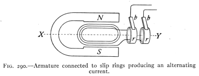 Fig. 290.—Armature linked to slip rings generating an alternating current.
303. Methods of Collecting Current from the Armature.—The electric currents produced in the armature are conducted away by special sliding contacts. The stationary part of the sliding contact is called a brush. The moving part is a slip ring or a commutator. Fig. 290 shows an armature coil connected to slip rings. As the armature revolves, the coils and slip rings revolve with it. The two ends of the armature coils are connected to the two rings respectively. Now as the armature revolves it cuts the lines of force first in one direction and then in the other. This produces in the coils an E.M.F. first one way and then the other. This E.M.F. sets up a current which is conducted to the outside circuits through the slip rings and[Pg 337] brushes. Such a current which repeatedly reverses its direction is called an alternating current. Fig. 291 (1) indicates graphically how the current moves alternately one way and then the other. Alternating currents are extensively used for electric light, heat, and power. Direct currents or those going continuously in one direction are however in much demand especially for street car service, for electrolysis, and for charging storage batteries.
303. Methods of Collecting Current from the Armature.—The electric currents generated in the armature are carried away by special sliding contacts. The stationary part of the sliding contact is called a brush. The moving part is a slip ring or a commutator. Fig. 290 shows an armature coil connected to slip rings. As the armature spins, the coils and slip rings rotate with it. The two ends of the armature coils connect to the two rings respectively. As the armature turns, it cuts through the lines of force in one direction and then the other. This generates an E.M.F. first one way and then the other. This E.M.F. creates a current that is sent to the outside circuits through the slip rings and [Pg 337] brushes. A current that continuously reverses its direction is called an alternating current. Fig. 291 (1) visually shows how the current alternates direction. Alternating currents are widely used for electric light, heat, and power. Direct currents, or those that flow consistently in one direction, are in high demand, especially for street car service, for electrolysis, and for charging storage batteries.
304. The Commutator.—For a dynamo to deliver a direct current it must carry upon the shaft of the armature a commutator. The commutator is used to reverse the connections of the ends of the armature coils at the instant that the current changes its direction in the armature. This reversal of connection when the direction of current changes, keeps the current in the outside circuit flowing in the same direction. Fig. 291 is a diagram of an armature with a commutator. The commutator is a split ring, having as many parts or segments as there are coils upon the armature. The brushes touch opposite points upon the commutator as they slide over the surface of the latter. Suppose that the armature viewed from the commutator end rotates in a counter-clockwise direction, also that the currents from the upper part move toward the commutator and out the top brush.
304. The Commutator.—For a dynamo to produce a direct current, it needs a commutator on the armature shaft. The commutator is used to reverse the connections of the armature coil ends at the moment the current changes direction in the armature. This connection reversal when the current direction changes keeps the current flowing in the same direction in the outside circuit. Fig. 291 is a diagram of an armature with a commutator. The commutator is a split ring, with as many parts or segments as there are coils on the armature. The brushes make contact with opposite points on the commutator as they slide across its surface. Suppose that the armature, seen from the commutator end, rotates in a counter-clockwise direction, and that the currents from the upper part move toward the commutator and out through the top brush.
 Fig. 291.—The armature coils are linked to a commutator that generates direct current.
As the armature revolves, its coils soon begin to cut the force lines in the opposite direction. This change in the direction of cutting the lines of force causes the current to reverse in the coils of the armature. At the instant the current changes in direction, what was the upper segment[Pg 338] of the commutator slips over into contact with the lower brush, and the other segment swings over to touch the upper brush. Since the current has reversed in the coils it continues to flow out of the upper brush. This change in connection at the brushes takes place at each half turn of the armature, just as the current changes in direction in the coils. This is the manner in which the commutator of a dynamo changes the alternating current produced in the armature coils, into a direct current in the external circuit. Fig. 292 (1) represents graphically an alternating current, (2) of the same figure shows current taken from the brushes of the commutator of a dynamo with one coil on the armature.
As the armature spins, its coils start to cut through the force lines in the opposite direction. This shift in the direction of cutting the force lines leads to a reversal of current in the armature's coils. The moment the current changes direction, what was the upper segment[Pg 338] of the commutator moves into contact with the lower brush, while the other segment shifts to touch the upper brush. Since the current has reversed in the coils, it continues to flow out of the upper brush. This change in connection at the brushes happens with every half turn of the armature, just as the current changes direction in the coils. This is how the commutator in a dynamo converts the alternating current produced in the armature coils into direct current in the external circuit. Fig. 292 (1) shows an alternating current graphically, and (2) of the same figure illustrates the current taken from the brushes of the commutator of a dynamo with one coil on the armature.
 Fig. 292.—Visual representation of (1) an alternating current; (2) a pulsating current; (3) a continuous current.
 Fig. 293.—DeLaval multi-stage turbine and gear driving a 750 kW, 750 RPM, 600-volt direct current generator.
A practical dynamo, however, has many coils upon its[Pg 339] armature with a corresponding number of segments upon the commutator. (See Figs. 289 and 293.) As each coil and commutator segment passes a brush, it contributes an impulse to the current with the result that armatures with many coils produce currents that flow quite evenly. (See Fig. 292, 3.)
A practical dynamo has several coils on its[Pg 339]armature, along with a matching number of segments on the commutator. (See Figs. 289 and 293.) As each coil and commutator segment comes into contact with a brush, it generates an impulse to the current, meaning that armatures with multiple coils create currents that flow smoothly. (See Fig. 292, 3.)
The current represented in Fig. 292 (2) is called a pulsating current.
The current shown in Fig. 292 (2) is called a pulsating current.
 Fig. 294.—A wire that carries an electric current through a magnetic field is pushed to the side by the field.
305. The electric motor is a machine which transforms the energy of an electric current into mechanical energy or motion. The direct current motor consists of the same essential parts as a direct current dynamo, viz., the field magnet, armature, commutator and brushes. Its operation is readily comprehended after one understands the following experiment:
305. The electric motor is a device that converts electrical energy into mechanical energy or movement. The direct current motor has the same key components as a direct current generator, namely the field magnet, armature, commutator, and brushes. Its functioning becomes easy to understand once one grasps the following experiment:
Set up two bar electromagnets with unlike poles facing each other about an inch apart. A wire connected to a source of current is hung loosely between the poles as in Fig. 294. The circuit through the wire should contain a key or switch. If a current is sent through the electromagnets and then another is sent through the wire, the[Pg 340] latter will be found to be pushed either up or down, while if the current is reversed through the wire it is pushed in the opposite direction. These results may be explained as follows:
Set up two bar electromagnets with opposite poles facing each other about an inch apart. A wire connected to a current source is hung loosely between the poles as shown in Fig. 294. The circuit through the wire should include a switch. When current flows through the electromagnets and then through the wire, the[Pg 340] wire will be pushed either up or down, and if the current in the wire is reversed, it will be pushed in the opposite direction. These results can be explained as follows:
Consider the magnetic field about a wire carrying a current (See Fig. 295.) If such a wire is placed in the magnetic field between two opposite poles of an electromagnet (Fig. 296), the wire will be moved either up or down. The reason for this is shown by the diagram in Fig. 297. Here a wire carrying a current and therefore surrounded by a magnetic field passes across another magnetic field. The two fields affect each other causing a crowding of the force lines either above or below the wire. The wire at once tends to move sideways across the field away from the crowded side. In the figure, the wire tends to move downward.
Consider the magnetic field around a wire that carries a current (See Fig. 295.) If this wire is placed in the magnetic field between two opposite poles of an electromagnet (Fig. 296), the wire will move either up or down. The reason for this is illustrated in the diagram in Fig. 297. Here, a wire carrying a current and, therefore, surrounded by a magnetic field crosses another magnetic field. The two fields affect each other, causing the force lines to crowd either above or below the wire. The wire immediately tends to move sideways across the field away from the crowded side. In the figure, the wire tends to move downward.
 Fig. 295.—The magnetic field around a wire carrying an electric current.
Fig. 296.—The magnetic field between two opposite poles.
 Fig. 297.—The concentration of the lines of force above the wire pushes it downward.
In a practical motor, the wires upon the armature are so connected that those upon one side (see Fig. 298), carry currents that pass in, while on the other side they pass out. To represent the direction of the current in the wires, the[Pg 341] following device is employed; a circle with a cross (to represent the feather in the tail of an arrow) indicates a current going away from the observer, while a circle with a dot at its center (to represent the tip of an arrow) indicates a current coming toward the observer.
In a practical motor, the wires on the armature are connected in such a way that those on one side (see Fig. 298) carry currents flowing in, while those on the other side carry currents flowing out. To show the direction of the current in the wires, the[Pg 341] following symbol is used: a circle with a cross (representing the feather on an arrow) indicates a current going away from the observer, while a circle with a dot in the center (representing the tip of an arrow) indicates a current coming toward the observer.
 Fig. 298.—The concentration of the lines of force makes the armature spin in a clockwise direction.
In Fig. 298 the north pole is at the left and the south pole at the right. The field of the magnets therefore passes from left to right as indicated in the figure. Now in the armature the currents in the wires on the left half of the armature are coming toward the observer while those on the right move away. Applying the right-hand rule, the magnetic lines will crowd under the wires on the left side of the armature while they will crowd over the wires on the right side. This will cause a rotation up on the left side and down on the right, or in a clockwise direction.
In Fig. 298, the north pole is on the left and the south pole is on the right. The magnetic field of the magnets therefore flows from left to right as shown in the figure. In the armature, the currents in the wires on the left side are moving toward the observer, while those on the right are moving away. Using the right-hand rule, the magnetic lines will bunch up under the wires on the left side of the armature, while they will gather over the wires on the right side. This will result in an upward rotation on the left side and a downward rotation on the right, or in a clockwise direction.
 Fig. 299.—Image of a half horsepower motor.
If the current in the armature is reversed (in on the left and out on the right), the lines of force will crowd the armature around in the opposite direction or counter clockwise. The rotation of the[Pg 342] armature will also be reversed if, while the current in the armature is unchanged in direction, the poles of the magnet are changed thus reversing the magnetic field.
If the current in the armature is reversed (input on the left and output on the right), the lines of force will push the armature in the opposite direction or counterclockwise. The rotation of the [Pg 342] armature will also be reversed if the current direction in the armature stays the same but the poles of the magnet are switched, which reverses the magnetic field.
The motorman of a street car reverses the motion of his car by reversing the direction of the current in the armature of the motor.
The operator of a streetcar changes the direction of the car by reversing the flow of the current in the armature of the motor.
 Fig. 300.—The frame and electromagnet (on the left), front bracket and brush holder (on the right) of the motor depicted in Fig. 299.
Fig. 301.—The armature of a motor.
306. Practical motors have many coils upon the armature with a corresponding number of segments upon the commutator. A large number of coils and commutator segments enables some one of the coils to exert its greatest efficiency at each instant, hence a steady force is provided for turning the armature which causes it to run smoothly.[Pg 343] Fig. 299 represents a 1/2 horse-power motor ready for use while Fig. 300 shows the frame and poles and the front bracket and brush holder, and Fig. 301 represents the armature.
306. Practical motors have several coils on the armature, corresponding to a matching number of segments on the commutator. A greater number of coils and commutator segments allows one of the coils to work at its full efficiency at any given moment, providing a consistent force to turn the armature, which helps it operate smoothly.[Pg 343] Fig. 299 shows a 1/2 horsepower motor ready for use, while Fig. 300 displays the frame, poles, front bracket, and brush holder, and Fig. 301 illustrates the armature.
Important Topics
1. The dynamo, four essential parts, action (a) for alternating currents, (b) for direct currents.
1. The dynamo has four key parts: (a) for alternating currents, and (b) for direct currents.
2. The electric motor: (a) essential parts, (b) action.
2. The electric motor: (a) key components, (b) operation.
Exercises
1. Why is an alternating current produced in the armature of a dynamo?
1. Why is alternating current generated in the armature of a dynamo?
2. How is this current produced? Give careful explanations.
2. How is this current generated? Please provide detailed explanations.
3. What is the result of Lenz's law as applied to the dynamo?
3. What is the outcome of Lenz's law when applied to the dynamo?
4. Apply the first two laws of electromagnetic induction to the dynamo.
4. Use the first two laws of electromagnetic induction on the dynamo.
5. What is the power of a dynamo if it produces 40 amperes of current at 110 volts?
5. What is the power of a dynamo if it generates 40 amperes of current at 110 volts?
6. How much power must be applied to this dynamo if its efficiency is 90 per cent.?
6. How much power do we need to use on this dynamo if it’s 90 percent efficient?
7. A motor takes 10 amperes of current at 220 volts; what is the power of the current in watts? If this motor has an efficiency of 95 per cent., how many horse-power of mechanical energy can it develop?
7. A motor uses 10 amperes of current at 220 volts; what is the power of the current in watts? If this motor has an efficiency of 95 percent, how many horsepower of mechanical energy can it produce?
8. Explain why reversing the current in the armature of a motor reverses the direction of rotation.
8. Explain why changing the direction of the current in the motor's armature reverses the rotation direction.
9. Find the cost of running a washing machine using a 1/2-horsepower motor 2 hours if the cost of the electricity is 10 cents a kilowatt hour.
9. Calculate the cost of operating a washing machine with a 1/2-horsepower motor for 2 hours if the electricity price is 10 cents per kilowatt-hour.
10. A 1/8-horse-power motor is used to run a sewing machine. If used for 3 hours what will be the cost at 11 cents a kilowatt hour?
10. A 1/8-horsepower motor is used to operate a sewing machine. If it runs for 3 hours, what will the cost be at 11 cents per kilowatt hour?
(3) The Induction Coil and the Transformer
307. The Induction Coil.—Practically all electric currents are produced either by voltaic cells or by dynamos. It is frequently found, however, that it is desirable to[Pg 344] change the E.M.F. of the current used, either for purposes of effectiveness, convenience, or economy. The induction coil and the transformer, devices for changing the E.M.F. of electric currents, are therefore in common use. The induction coil (see Fig. 302) consists of a primary coil of coarse wire P (Fig. 303) wound upon a core of soft iron wire, and a secondary coil, S, of several thousand turns of fine wire. In circuit with the primary coil is a battery, B, and a current interrupter, K, which works like the interrupter upon an electric bell. The ends of the secondary coil are brought to binding posts or spark points as at D.
307. The Induction Coil.—Almost all electric currents are generated either by batteries or by generators. However, it's often necessary to[Pg 344] adjust the E.M.F. of the current used, whether for efficiency, convenience, or cost-effectiveness. The induction coil and the transformer, which are devices for changing the E.M.F. of electric currents, are therefore widely used. The induction coil (see Fig. 302) consists of a primary coil of thick wire P (Fig. 303) wound around a core of soft iron wire, along with a secondary coil, S, with several thousand turns of thin wire. Connected to the primary coil is a battery, B, and a current interrupter, K, which operates like the interrupter on an electric bell. The ends of the secondary coil are connected to binding posts or spark points at D.
 Fig. 302.—A transformer coil.
The current from the battery flows through the primary coil magnetizing the iron core. The magnetism in the core attracts the soft-iron end of the interrupter, drawing the latter over and breaking the circuit at the screw contact, K. This abruptly stops the current and at once the core loses its magnetism. The spring support of the interrupter now draws the latter back to the contact, T, again completing the circuit. The whole operation is repeated, the interrupter vibrating rapidly continually opening and closing the circuit.
The current from the battery flows through the primary coil, magnetizing the iron core. The magnetism in the core attracts the soft-iron end of the interrupter, pulling it over and breaking the circuit at the screw contact, K. This suddenly stops the current, and immediately the core loses its magnetism. The spring support of the interrupter then pulls it back to the contact, T, completing the circuit again. The entire process repeats, with the interrupter vibrating quickly, continuously opening and closing the circuit.
 Fig. 303.—Diagram illustrating the components of an induction coil.
308. The Production of Induced Currents in the Secondary Coil.—When the current flows through the[Pg 345] primary it sets up a magnetic field in the core. When the current is interrupted, the field disappears. The increase and decrease in the field of the core induces an E.M.F. in the secondary coil, in accordance with the first law of electromagnetic induction. The E.M.F. produced depends upon (a) the number of turns in the secondary, (b) the strength of the magnetic field and (c) the rate of change of the field. The rate of change in the field is more rapid at the break than at the make. When the circuit is closed it takes perhaps 1/10 of a second for the current to build up to its full strength while at a break the current stops in perhaps 0.00001 of a second, so that the induced E.M.F. is perhaps 10,000 times as great at "break" as at make. To increase the suddenness of the "make" and "break," a condenser is often connected in the primary circuit, in parallel, with the interrupter. (See Fig. 303, C.) This condenser provides a place to hold the rush of current at the instant that the interrupter breaks the circuit. This stored up charge reinforces the current at the make producing a much more sudden change in the magnetic field with a corresponding increase in the E.M.F. The induced currents from induction coils are sometimes called faradic currents in honor of Faraday who discovered electromagnetic induction. They are used to operate sparking devices upon gas and gasoline engines and in many devices and experiments in which high-tension electricity is employed.
308. The Production of Induced Currents in the Secondary Coil.—When the current flows through the [Pg 345] primary, it creates a magnetic field in the core. When the current is stopped, the field disappears. The increase and decrease in the field of the core induces an E.M.F. in the secondary coil, following the first law of electromagnetic induction. The E.M.F. produced depends on (a) the number of turns in the secondary, (b) the strength of the magnetic field, and (c) the rate of change of the field. The rate of change in the field is faster at the break than at the make. When the circuit is closed, it takes about 1/10 of a second for the current to reach its full strength, while at a break, the current stops in about 0.00001 of a second, making the induced E.M.F. around 10,000 times greater at "break" than at "make." To enhance the abruptness of the "make" and "break," a capacitor is often connected in the primary circuit, in parallel, with the interrupter. (See Fig. 303, C.) This capacitor provides a way to hold the rush of current at the moment the interrupter breaks the circuit. This stored charge boosts the current at the "make," creating a much sharper change in the magnetic field with a corresponding increase in the E.M.F. The induced currents from induction coils are sometimes referred to as faradic currents in honor of Faraday, who discovered electromagnetic induction. They are used to operate sparking devices in gas and gasoline engines and in many devices and experiments involving high-tension electricity.
 Fig. 304.—The transformer has a closed core, while the induction coil has an open core.
 Fig. 305.—The laminated iron core of a transformer.
Fig. 306.—Cross-section of the transformer shown in Fig. 305, illustrating the magnetic field around the primary and secondary coils.
309. The Transformer.—This is like the induction coil in that it uses a primary and a secondary coil, and an iron core to carry the magnetic field. (See Fig. 304.) They differ in that the transformer has a closed core or one forming a continuous iron circuit, while the induction coil has an open core, or one in which the magnetic field must travel in air from the north to the south poles of the core. The[Pg 346] transformer must always be used with an alternating current while the induction coil may use either a direct or an alternating current. Further, the induction coil always produces a higher E.M.F. while the transformer may produce an E.M.F. in its secondary coil that is either higher or lower than the one in the primary. The former is called "step-up" while the latter is a "step-down" transformer. The alternating current in the primary coil of the transformer produces an alternating magnetic flux in the iron core. This iron core is laminated (see Fig. 305) to prevent the heating that would result if a solid core were used. The alternating magnetic flux induces in the secondary coil an E.M.F. in accordance with the following rule. The[Pg 347] ratio of the number of turns in the primary to the number of the turns in the secondary coil equals the ratio of the electromotive forces in these respective coils. If the secondary coil has 8 turns while the primary has 4, the E.M.F. of the secondary will be just twice that of the primary. Or, if in the primary coil of the transformer Fig. 306 is an E.M.F. of 110 volts, in the secondary will be found an E.M.F. of 220 volts.
309. The Transformer.—This works like an induction coil because it uses a primary and a secondary coil, along with an iron core to transmit the magnetic field. (See Fig. 304.) However, the transformer has a closed core that forms a continuous iron circuit, while the induction coil has an open core, where the magnetic field travels through air from the north to the south poles of the core. The [Pg 346] transformer must always be used with an alternating current, while the induction coil can use either direct or alternating current. Additionally, the induction coil always produces a higher E.M.F., whereas the transformer can produce an E.M.F. in its secondary coil that is either higher or lower than in the primary. The former is referred to as a "step-up" transformer, while the latter is called a "step-down" transformer. The alternating current in the primary coil of the transformer creates an alternating magnetic flux in the iron core. This iron core is laminated (see Fig. 305) to prevent the overheating that would occur if a solid core were used. The alternating magnetic flux generates an E.M.F. in the secondary coil according to the following principle: The[Pg 347] ratio of the number of turns in the primary coil to the number of turns in the secondary coil equals the ratio of the electromotive forces in those coils. For example, if the secondary coil has 8 turns while the primary has 4, the E.M.F. in the secondary will be twice that in the primary. So, if the primary coil of the transformer in Fig. 306 has an E.M.F. of 110 volts, the secondary will have an E.M.F. of 220 volts.
 Fig. 307.—A commercial transformer.
310. Uses of Transformers.—In electric lighting systems, dynamos often produce alternating currents at 1000 to 12,000 volts pressure. It is very dangerous to admit currents at this pressure into dwellings and business houses, so that transformers are installed just outside of buildings to "step-down" the high voltage currents to 110 or 220 volts. The lighting current that enters a house does not come directly from a dynamo. It is an induced current produced by a transformer placed near the house. (See Fig. 307.) In a perfect transformer the efficiency would be 100 per cent. This signifies that the energy that is sent into the primary coil of the transformer exactly equals the energy in the secondary coil. The best transformers actually show efficiencies better than 97 per cent. The lost energy appears as heat in the transformer. "The transfer of great power in a large transformer from one circuit to another circuit entirely separate and distinct, without any motion or noise and almost without loss, is one of the most wonderful phenomena under the control of man."
310. Uses of Transformers.—In electric lighting systems, generators often produce alternating currents at 1000 to 12,000 volts. It's very dangerous to bring currents at this voltage into homes and businesses, so transformers are placed just outside buildings to "step down" the high voltage currents to 110 or 220 volts. The electricity that comes into a house doesn't come directly from a generator. It’s an induced current created by a transformer located near the house. (See Fig. 307.) In a perfect transformer, the efficiency would be 100 percent. This means the energy going into the primary coil of the transformer exactly matches the energy in the secondary coil. The best transformers actually achieve efficiencies better than 97 percent. The lost energy shows up as heat in the transformer. "The transfer of large amounts of power in a big transformer from one circuit to another completely separate circuit, without any motion or noise and almost without loss, is one of the most amazing phenomena under human control."
311. The mercury arc rectifier is a device for changing an alternating current into a direct current. It is frequently used for charging storage batteries where only alternating current is supplied by the electric power company.[Pg 348] It consists of an exhausted bulb containing two carbon or graphite electrodes marked G in Fig. 308 and a mercury electrode marked M. It is found that current will pass through such a bulb only from the graphite to the mercury but not in the reverse direction. In operating the device, the secondary terminals of an alternating current transformer T are connected to the graphite terminals of the rectifier. A wire connected to the center of the secondary of the transformer at C is attached to the negative terminal of the storage battery SB. The positive terminal of the battery is connected to the mercury electrode of the rectifier tube through a reactance or choke coil R. This coil serves to sustain the arc between the alternations. Sw is a starting switch, used only in striking the arc. It is opened immediately after the tube begins to glow.
311. The mercury arc rectifier is a device that converts alternating current into direct current. It's often used for charging storage batteries when the electric power company only provides alternating current.[Pg 348] It consists of an evacuated bulb containing two carbon or graphite electrodes labeled G in Fig. 308 and a mercury electrode labeled M. It's noted that current will flow through this bulb only from the graphite to the mercury and not in the opposite direction. To operate the device, the secondary terminals of an alternating current transformer T are connected to the graphite terminals of the rectifier. A wire connected to the center of the transformer's secondary at C is linked to the negative terminal of the storage battery SB. The positive terminal of the battery is connected to the mercury electrode of the rectifier tube through a reactance or choke coil R. This coil helps maintain the arc between alternating current cycles. Sw is a starting switch that is only used to initiate the arc and is opened immediately after the tube begins to glow.
 Fig. 308.—Diagram of a mercury arc rectifier.
Important Topics
Transformer, induction coil, mercury arc rectifier, construction, action; uses of each.
Transformer, induction coil, mercury arc rectifier, construction, function; applications of each.
Exercises
1. Does the spark of an induction coil occur at "make" or at "break?" Why?
1. Does the spark from an induction coil happen when you turn it on or when you turn it off? Why?
2. What must be the relative number of turns upon the primary and secondary coils of a transformer if it receives current at[Pg 349] 220 volts and delivers current at 110? Also show by diagram.
2. How many turns should there be on the primary and secondary coils of a transformer if it receives current at[Pg 349] 220 volts and delivers current at 110? Please also include a diagram.
3. Would the transformer work upon a direct current? Why?
3. Would the transformer work with direct current? Why?
4. Explain why the interrupter is a necessary part of the induction coil and not of the transformer.
4. Explain why the interrupter is an essential part of the induction coil and not of the transformer.
5. If a building used eighty 110-volt incandescent lamps, what would be necessary to light them if they were joined in series? Why would this not be practical?
5. If a building used eighty 110-volt incandescent bulbs, what would be needed to power them if they were connected in series? Why wouldn’t this be practical?
6. If a 16-candle-power lamp requires 0.5 ampere upon a 110-volt circuit what current and voltage will be needed to operate 12 such lamps in parallel?
6. If a 16-candle-power lamp needs 0.5 amp on a 110-volt circuit, what current and voltage will be needed to run 12 of these lamps in parallel?
7. What will it cost to run these lamps 4 hours a night for 30 days at 10 cents per kilowatt hour?
7. What will it cost to run these lamps for 4 hours a night for 30 days at 10 cents per kilowatt-hour?
8. If a mercury arc rectifier uses 5 amperes of current at 110 volts alternating current to produce 5 amperes of direct current at 70 volts, what is the efficiency of the rectifier?
8. If a mercury arc rectifier uses 5 amps of current at 110 volts AC to produce 5 amps of direct current at 70 volts, what is the efficiency of the rectifier?
9. Compute the heat produced in a 40 watt tungsten lamp in 1 minute.
9. Calculate the heat generated by a 40-watt tungsten lamp in 1 minute.
10. Compute the heat produced in a 60 watt carbon incandescent lamp in 1 hour.
10. Calculate the heat generated by a 60-watt carbon incandescent lamp in 1 hour.
(4) The Phone
312. The Electric Telephone.—This is an instrument for reproducing the human voice at a distance by an electric current. The modern electric telephone consists of at least four distinct parts (see Fig. 312); viz., a transmitter, an induction coil, an electric battery, and a receiver. The first three of these are concerned in sending, or transmitting over the connecting wires a fluctuating electric current, which has been modified by the waves of a human voice. The receiver, is affected by the fluctuating current and reproduces the voice. It will be considered first, in our study.
312. The Electric Telephone.—This is a device for transmitting the human voice over long distances using an electric current. The modern electric telephone has at least four distinct parts (see Fig. 312): a transmitter, an induction coil, an electric battery, and a receiver. The first three parts are involved in sending, or transmitting, a fluctuating electric current through the connecting wires, modified by the sound waves of a human voice. The receiver responds to the fluctuating current and reproduces the voice. We will examine it first in our study.
313. The telephone receiver was invented in 1876 by Alexander Graham Bell. It consists of a permanent steel magnet, U shaped, with a coil of fine insulated copper wire about each pole. (See Fig. 310.) A disc of thin sheet iron is supported so that its center does not quite touch the[Pg 350] poles of the magnet. A hard rubber cap or ear piece with an opening at its center is screwed on so as to hold the iron disc firmly in place.
313. The telephone receiver was invented in 1876 by Alexander Graham Bell. It consists of a permanent steel magnet shaped like a U, with a coil of fine insulated copper wire around each pole. (See Fig. 310.) A thin sheet iron disc is held in place so that its center doesn’t quite touch the [Pg 350] poles of the magnet. A hard rubber cap or earpiece with a central opening is screwed on to keep the iron disc securely in place.
 Fig. 309.—The most basic telephone system. It includes two telephone receivers wired in series on a circuit. It will function, but not very well.
The action of the receiver may be understood from the following explanation: The electric current sent to the receiver, comes from the secondary coil of the induction coil; it is an alternating current, fluctuating back and forth just in time with the waves of the voice affecting it at the transmitter. This alternating current flows around the coils on the poles of the permanent magnet. When this current flows in one direction, its magnetic field assists the field of the permanent magnet, strengthening it. This stronger magnetic field draws the thin iron disc in front of the poles of the magnet a little closer to them. When the current in the coils flows the other way, its magnetic field weakens the field of the steel magnet, and the disc is drawn back by the force of its own elasticity. Thus the disc of the receiver vibrates with the alternations of the current, and reproduces the same sounds that were spoken into the transmitter.
The action of the receiver can be explained as follows: The electric current sent to the receiver comes from the secondary coil of the induction coil; it's an alternating current, fluctuating back and forth in sync with the sound waves it receives at the transmitter. This alternating current flows around the coils on the poles of the permanent magnet. When the current flows in one direction, its magnetic field enhances the field of the permanent magnet, making it stronger. This stronger magnetic field pulls the thin iron disc in front of the magnet's poles a bit closer. When the current in the coils flows the other way, its magnetic field weakens the steel magnet's field, and the disc is pulled back by its own elasticity. As a result, the receiver's disc vibrates with the changes in the current, reproducing the same sounds that were spoken into the transmitter.
 Fig. 310.—A telephone receiver. This receiver features a permanent horseshoe magnet with a coil around each pole.
314. The Telephone Transmitter.—The telephone receiver just described has great sensitiveness in reproducing sound, but it is not satisfactory as a transmitter or sending apparatus. The transmitter commonly used is represented in cross-section in Fig. 311. In this figure, back of the mouthpiece, is a thin carbon disc, D. Back of this[Pg 351] disc is a circular compartment containing granular carbon, g. The wires of the circuit are connected to the carbon disc and to the back of the case containing granular carbon. The circuit through the transmitter also includes a voltaic or storage cell and the primary coil of an induction coil. (See Fig. 312.)
314. The Telephone Transmitter.—The telephone receiver described earlier is very sensitive in reproducing sound, but it doesn't work well as a transmitter or sending device. The transmitter typically used is shown in cross-section in Fig. 311. In this figure, behind the mouthpiece is a thin carbon disc, D. Behind this disc is a circular compartment filled with granular carbon, g. The circuit wires are connected to the carbon disc and to the back of the case holding the granular carbon. The circuit through the transmitter also includes a battery or storage cell and the primary coil of an induction coil. (See Fig. 312.)
 Fig. 311.—A telephone transmitter.
Fig. 312.—Telephone devices at one end of a conversation circuit.
315. The action of the transmitter is explained as follows: When the sound waves of the voice strike upon the carbon disc, the latter vibrates, alternately increasing and decreasing the pressure upon the granular carbon. When the pressure increases, the electrical resistance of the granular carbon is lessened, and when the pressure upon it is decreased, its resistance increases. This changing resistance causes fluctuations in the electric current that correspond exactly with the sound waves of the voice affecting it.
315. The action of the transmitter is explained as follows: When sound waves from the voice hit the carbon disc, it vibrates, which alternately increases and decreases the pressure on the granular carbon. When the pressure increases, the electrical resistance of the granular carbon decreases, and when the pressure decreases, its resistance increases. This changing resistance creates fluctuations in the electric current that exactly match the sound waves of the voice impacting it.
316. A complete telephone system operating with a local battery is shown in Fig. 312. A person speaking into the transmitter causes a fluctuation in the electric current in the transmitter as described in Art. 315. This fluctuating current passes through the primary coil of the induction coil Ic. This fluctuating current produces a fluctuating magnetic field in its core. This fluctuating field induces an alternating current in the secondary coil which alternates just as the primary current fluctuates,[Pg 352] but with a much higher E.M.F. than the latter. The alternating current passes to the receiver which reproduces the speech as described in Art. 313. The line circuit includes the secondary of the induction coil, the receiving instrument and the receiver of the sending instrument so that the voice is reproduced in both receivers. An electric bell is placed at each station to call the attention of parties wanted. The movement of the receiver hook when the receiver is lifted, disconnects the bell and closes the talking circuit. The latter is opened and the bell connected when the receiver is hung up again.
316. A complete telephone system operating with a local battery is shown in Fig. 312. When someone speaks into the transmitter, it creates fluctuations in the electric current as described in Art. 315. This fluctuating current flows through the primary coil of the induction coil Ic. The fluctuating current generates a fluctuating magnetic field in its core. This magnetic field induces an alternating current in the secondary coil, which alternates just like the primary current, [Pg 352] but with a much higher voltage than the primary current. The alternating current then goes to the receiver, reproducing the speech as detailed in Art. 313. The line circuit includes the secondary of the induction coil, the receiving instrument, and the receiver of the sending instrument, allowing the voice to be heard in both receivers. An electric bell is installed at each station to alert the people being contacted. When the receiver is lifted, the movement of the receiver hook disconnects the bell and closes the talking circuit. When the receiver is hung up again, the circuit opens, and the bell is reconnected.
 Fig. 313.—Diagram of a telephone system used in a large exchange.
In cities and towns, the telephone system in use differs from the one described in usually having one large battery placed in the central exchange, instead of dry cells at each instrument. (See Fig. 313.) Also the operator at central is called by simply taking the receiver from the hook instead of being "rung up" by the subscriber. The operations of the transmitter, induction coil and receiver, however, are the same in all telephones.
In cities and towns, the telephone system in use differs from the one described by typically having one large battery situated in the central exchange, rather than dry cells at each phone. (See Fig. 313.) Additionally, the operator at central is reached by just lifting the receiver off the hook instead of being "rung up" by the subscriber. However, the functions of the transmitter, induction coil, and receiver remain the same in all telephones.
Important Topics
1. Receiver: parts, action.
Receiver: components, activity.
2. Transmitter: parts, action.
2. Transmitter: components, operation.
3. Induction coil, bell, line wires, etc.
3. Induction coil, bell, line wires, etc.
4. Action of the whole device.
4. The action of the entire device.
Exercises
1. State three important electrical laws or principles that are employed in the operation of the telephone. What is the application of each?
1. Name three key electrical laws or principles used in how telephones work. What is the purpose of each?
2. Connect the binding posts of a telephone receiver with a sensitive galvanometer and press on the diaphragm of the receiver; a deflection of the galvanometer will be noticed. Release the diaphragm and a reflection in the opposite direction is seen. Explain.
2. Connect the binding posts of a telephone receiver to a sensitive galvanometer and press on the diaphragm of the receiver; you'll notice a deflection in the galvanometer. Release the diaphragm, and a deflection in the opposite direction is observed. Explain.
3. Is the current passing through the transmitter the one going to the receiver of the instrument? Explain.
3. Is the current flowing through the transmitter the same one that goes to the instrument's receiver? Explain.
4. Does the receiver at the telephone used by a person repeat the speech of the person? Explain.
4. Does the person on the other end of the phone repeat what the caller says? Explain.
5. How many 0.5 ampere lamps can be used with a 6 ampere fuse?
5. How many 0.5 amp lamps can you use with a 6 amp fuse?
6. Why is it necessary to have a rheostat connected in series with a stereopticon or moving picture machine while a rheostat is not used with arc lights out doors?
6. Why is it necessary to have a rheostat connected in series with a projector or movie projector, while a rheostat is not used with outdoor arc lights?
7. How many candle power should a 60 watt carbon incandescent lamp give, if its efficiency is 3.4 watts per candle power?
7. How many candlepower should a 60-watt carbon incandescent lamp produce if its efficiency is 3.4 watts per candlepower?
8. Three incandescent lamps having resistances of 100, 150, and 240 ohms, respectively, are connected in parallel. What is their combined resistance?
8. Three incandescent bulbs with resistances of 100, 150, and 240 ohms, respectively, are connected in parallel. What is their total resistance?
Review Outline: Induced Currents
Induced currents; 3 laws, illustrations.
Induced currents: 3 laws, illustrations.
Construction, action, and uses of—magneto, dynamo, induction coil, transformer, motor, telephone. Mercury arc rectifier.
Construction, operation, and applications of—magneto, dynamo, induction coil, transformer, motor, telephone. Mercury arc rectifier.
Terms—primary, secondary, for coils and currents, armature, commutator, slip ring, brush, rectifier, open core, series, shunt, and compound connections for dynamos.
Terms—primary, secondary, for coils and currents, armature, commutator, slip ring, brush, rectifier, open core, series, shunt, and compound connections for dynamos.
CHAPTER XV
SOUND
AUDIO
(1) Sound and Wave Movement
317. What is a Sound?—This question has two answers, which may be illustrated as follows: Suppose that an alarm clock is set so that it will strike in one week and that it is placed upon a barren rock in the Pacific Ocean by sailors who immediately sail away. If when the tapper strikes the bell at the end of the week no ear is within a hundred miles, is any sound produced? The two view-points are now made evident, for some will answer "no" others "yes." Those answering "no" hold that sound is a sensation which would not be produced if no ear were at hand to be affected. Those answering "yes" understand, by the term sound, a mode of motion capable of affecting the auditory nerves, and that sound exists wherever such motions are present. This latter point of view is called the physical and is the one we are to use in this study.
317. What is a Sound?—This question has two answers, which can be explained as follows: Imagine an alarm clock set to ring in one week, placed on a deserted rock in the Pacific Ocean by sailors who then leave. If, when the clapper hits the bell at the end of the week, no one is within a hundred miles, is any sound produced? The two perspectives become clear: some will say "no," while others will say "yes." Those who say "no" believe that sound is a sensation that wouldn’t occur without an ear to perceive it. Those who say "yes" define sound as a type of motion capable of affecting the auditory nerves, and they believe that sound exists wherever those motions are present. This latter perspective is known as the physical view, and it’s the one we will use in this study.
 Fig. 314.—The tuning fork is vibrating.
318. Source of Sound.—If we trace any sound to its source, it will be found to originate in a body in rapid motion usually in what is called a state of vibration. To illustrate, take a tuning fork, strike it to set it in vibration and place its stem firmly against a thin piece of wood; the sound will be strengthened materially by the vibration[Pg 355] of the wood. If now the vibrating fork is placed with the tips of the prongs in water, the vibration is plainly shown by the spattering of the water (Fig. 314). When one speaks, the vibrating body is in the larynx at the top of the windpipe. Its vibration may be plainly felt by the hand placed upon the throat while speaking.
318. Source of Sound.—When we trace any sound to its source, we find that it comes from an object in rapid motion, usually in a state of vibration. For example, take a tuning fork, strike it to make it vibrate, and press its stem firmly against a thin piece of wood; the sound will be significantly amplified by the vibration[Pg 355] of the wood. If the vibrating fork is then placed with the tips of the prongs in water, the vibration is clearly demonstrated by the splashing of the water (Fig. 314). When someone speaks, the vibrating body is in the larynx at the top of the windpipe. This vibration can be easily felt by placing a hand on the throat while speaking.
319. Sound Media.—Usually sounds reach the ear through the air. The air is then said to be a medium for sound. Other substances may serve as a sound medium, for if the head is under water and two stones, also under water, are struck together a sharp sound is heard. Also if one end of a wooden rod is held at the ear and the other end of the rod is scratched by a pin, the sound is more plainly perceived through the wood than through the air. Think of some illustration from your own experience of a solid acting as medium for sound. If an electric bell is placed in a bell jar attached to an air pump, as in Fig. 315, on exhausting the air the loudness of the sound is found to diminish, indicating that in a perfect vacuum no sound would be transmitted. This effect of a vacuum upon the transmission of sound is very different from its effect upon radiation of heat and light. Both heat and light are known to pass through a vacuum since both come to the earth from the sun through space that so far as we know contains no air or other matter. Sound differs from this in that it is always transmitted by some material body and cannot exist in a vacuum.
319. Sound Media.—Sounds typically reach our ears through the air, which is referred to as a medium for sound. Other materials can also act as sound mediums. For example, if your head is underwater and two stones are struck together underwater, you can hear a sharp sound. Similarly, if you hold one end of a wooden rod to your ear and scratch the other end with a pin, the sound is much clearer through the wood than through the air. Think of a time when you experienced a solid acting as a medium for sound. If an electric bell is placed inside a bell jar connected to an air pump, as shown in Fig. 315, you will notice that when the air is pumped out, the loudness of the sound decreases, indicating that in a complete vacuum, no sound would be transmitted. This effect of a vacuum on sound transmission is quite different from its impact on the transmission of heat and light. Both heat and light can travel through a vacuum, as they reach Earth from the sun through space, which, as far as we know, has no air or other matter. Unlike this, sound always requires a material medium to travel through and cannot exist in a vacuum.
 Fig. 315.—Sound doesn't travel in a vacuum.
320. Speed of Sound.—Everyone has noticed that it takes time for sound to travel from one place to another. If we see a gun fired at a distance, the report is heard a few seconds after the smoke or flash is seen. The time[Pg 356] elapsing between a flash of lightning and the thunder shows that sound takes time to move from one place to another. Careful experiments to determine the speed of sound have been made. One method measures accurately the time required for the sound of a gun to pass between two stations several miles apart. A gun or cannon is placed at each station. These are fired alternately, first the one at one station and then the one at the other so as to avoid an error in computation due to the motion of wind. This mode of determining the speed of sound is not accurate. Other methods, more refined than the one just described have given accurate values for the speed of sound. The results of a number of experiments show that, at the freezing temperature, 0°C., the speed of sound in air is 332 meters or 1090 ft. a second. The speed of sound in air is affected by the temperature, increasing 2 ft. or 0.6 meter per second for each degree that the temperature rises above 0°C. The speed decreases the same amount for each degree C. that the air is cooled below the freezing point. The speed of sound in various substances has been carefully determined. It is greater in most of them than in air. In water the speed is about 1400 meters a second; in wood, while its speed varies with different kinds, it averages about 4000 meters a second; in brass the speed is about 3500 meters; while in iron it is about 5100 meters a second.
320. Speed of Sound.—Everyone has noticed that sound takes time to travel from one place to another. When we see a gun fired in the distance, the sound is heard a few seconds after the flash or smoke is visible. The interval between a flash of lightning and the thunder shows that sound requires time to move from one location to another. Careful experiments have been conducted to measure the speed of sound. One method accurately measures the time it takes for the sound of a gun to travel between two stations several miles apart. A gun or cannon is positioned at each station and fired alternately, starting with one station and then the other, to avoid errors due to wind movement. This way of determining the speed of sound is not entirely accurate. More refined methods have provided precise values for the speed of sound. Results from various experiments indicate that at freezing point, 0°C, the speed of sound in air is 332 meters or 1090 feet per second. The speed of sound in air is influenced by temperature, increasing by 2 feet or 0.6 meters per second for each degree above 0°C, and decreasing by the same amount for each degree Celsius below freezing. The speed of sound in different substances has been carefully measured and is generally higher than in air. In water, the speed is about 1400 meters per second; in wood, while it varies among types, it averages about 4000 meters per second; in brass, the speed is about 3500 meters; and in iron, it reaches about 5100 meters per second.
321. The Nature of Sound.—We have observed that sound originates at a vibrating body, that it requires a medium in order to be transmitted from one place to another, and that it travels at a definite speed in a given substance. Nothing has been said, however, of the mode of transmission, or of the nature of sound. Sounds continue to come from an alarm clock even though it is placed under a bell jar. It is certain that nothing material can pass[Pg 357] through the glass of the jar. If, however, we consider that sound is transmitted by waves through substances the whole matter can be given a simple explanation. In order to better understand the nature of sound a study of waves and wave motion will be taken up in the next section.
321. The Nature of Sound.—We've noticed that sound comes from a vibrating object, that it needs a medium to travel from one location to another, and that it moves at a specific speed in a particular substance. However, we haven't discussed the way it travels or the essence of sound. Sounds continue to come from an alarm clock even when it's placed under a bell jar. It's clear that nothing physical can pass[Pg 357] through the glass of the jar. However, if we consider that sound is transmitted through waves in substances, everything can be explained simply. To better understand the nature of sound, we'll explore waves and wave motion in the next section.
Important Topics
Sound: two definitions, source, medium, speed, nature.
Sound: two definitions, source, medium, speed, nature.
Exercises
1. Give two illustrations from outside the laboratory of the fact that sound is transmitted by other materials than air.
1. Provide two examples from outside the lab showing that sound can travel through materials other than air.
2. Name the vibrating part that is the source of the sound in three different musical instruments.
2. Name the vibrating part that produces sound in three different musical instruments.
3. Is sound transmitted more strongly in solids, liquids or gases? How do you explain this?
3. Is sound transmitted better in solids, liquids, or gases? What’s your explanation for this?
4. How far away is a steamboat if the sound of its whistle is heard 10 seconds after the steam is seen, the temperature being 20°C.? Compute in feet and in meters.
4. How far away is a steamboat if you hear its whistle 10 seconds after you saw the steam, with the temperature at 20°C? Calculate in feet and meters.
5. How many miles away is lightning if the thunder is heard 12 seconds after the flash in seen, the temperature being 25°C.?
5. How far away is lightning if the thunder is heard 12 seconds after the flash is seen, with the temperature being 25°C?
6. Four seconds after a flash of lightning is seen the thunder clap is heard. The temperature is 90°F. How far away was the discharge?
6. Four seconds after a flash of lightning is seen, the thunder is heard. The temperature is 90°F. How far away was the discharge?
7. The report of a gun is heard 3 seconds after the puff of smoke is seen. How far away is the gun if the temperature is 20°C.?
7. The sound of a gun is heard 3 seconds after the puff of smoke is seen. How far away is the gun if the temperature is 20°C?
8. An explosion takes place 10 miles away. How long will it take the sound to reach you, the temperature being 80°F?. How long at 0°F.?
8. An explosion happens 10 miles away. How long will it take for the sound to reach you if the temperature is 80°F? How long would it take at 0°F?
9. How long after a whistle is sounded will it be heard if the distance away is 1/4 mile, the temperature being 90°F.?
9. How long will it take for a whistle to be heard if it's 1/4 mile away and the temperature is 90°F?
10. The report of an explosion of dynamite is heard 2 minutes after the puff of smoke is seen. How far away is the explosion the temperature being 77°F.?
10. The sound of a dynamite explosion is heard 2 minutes after the puff of smoke is seen. How far away is the explosion if the temperature is 77°F?
(2) Waves and Wave Motion
322. Visible Waves.—It is best to begin the study of wave motion by considering some waves which are familiar[Pg 358] to most persons. Take for example the waves that move over the surface of water (Fig. 316). These have an onward motion, yet boards or chips upon the surface simply rise and fall as the waves pass them. They are not carried onward by the waves. The water surface simply rises and falls as the waves pass by. Consider also the waves that may be seen to move across a field of tall grass or grain. Such waves are produced by the bending and rising of the stalks as the wind passes over them. Again, waves may be produced in a rope fastened at one end, by suddenly moving the other end up and down. These waves move to the end of the rope where they are reflected and return. The three types of waves just mentioned are illustrations of transverse waves, the ideal case being that in which the particles move at right angles to the path or course of the wave. Such waves are therefore called transverse waves.
322. Visible Waves.—It's best to start studying wave motion by looking at some waves that most people are familiar with[Pg 358]. For example, consider the waves that move across the surface of water (Fig. 316). These waves move forward, but boards or chips on the surface simply go up and down as the waves pass by. They aren’t carried along by the waves. The water surface just rises and falls as the waves move through. Also, think about the waves that you can see moving across a field of tall grass or grain. These waves are created by the bending and rising of the stalks as the wind blows over them. Additionally, waves can be created in a rope that’s secured at one end by quickly moving the other end up and down. These waves travel to the end of the rope where they are reflected and come back. The three types of waves mentioned here are examples of transverse waves, which are defined by particles moving at right angles to the wave's path. Therefore, these waves are referred to as transverse waves.
 Fig. 316.—Ocean waves.
323. Longitudinal waves.—Another kind of wave is found in bodies that are elastic and compressible and have inertia, such as gases and coiled wire springs. Such waves may be studied by considering a wire spring as the medium through which the waves pass. (See Fig. 318.)
323. Longitudinal waves.—Another type of wave occurs in materials that are elastic, compressible, and have inertia, like gases and coiled wire springs. These waves can be examined by looking at a wire spring as the medium through which the waves travel. (See Fig. 318.)
 Fig. 317.—The compression wave moves through the spring.
If the end of the wire spring shown in Fig. 317 is struck the first few turns of the spring will be compressed. Since the spring possesses elasticity, the turns will move forward a little and compress those ahead, these will press the next in turn and so on. Thus a compression wave will move to the end of the spring, where it will be reflected and return. Consider the turns of the spring as they[Pg 359] move toward the end. On account of their inertia they will continue moving until they have separated from each other more than at first, before returning to their usual position. This condition of a greater separation of the turns of the spring than usual is called a rarefaction. It moves along the spring following the wave of compression. The condensation and rarefaction are considered as together forming a complete wave. Since the turns of wire move back and forth in a direction parallel to that in which the wave is traveling, these waves are called longitudinal.
If the end of the wire spring shown in Fig. 317 is hit, the first few coils of the spring will get compressed. Because the spring has elasticity, the coils will shift forward a bit and compress the ones in front of them, which will then compress the next ones, and so on. This creates a compression wave that travels to the end of the spring, where it will bounce back. Think about the coils of the spring as they[Pg 359] move toward the end. Due to their inertia, they will keep moving until they are spread apart more than they were initially, before returning to their normal position. This state of the coils being more separated than usual is called a rarefaction. It travels along the spring following the compression wave. The compression and rarefaction together make up a complete wave. Because the coils of wire move back and forth in a direction parallel to the wave's travel, these waves are termed longitudinal.
 Fig. 318.—Longitudinal waves (1) in a spring, (2) in air, and (3) a graphic representation showing wavelength, compressions, and rarefactions.
324. The transmission of a sound by the air may be understood by comparing it with the process by which a wave is transmitted by a wire spring. Consider a light spring (Fig. 318, 1) attached at the end of a vibrating tuning fork, K, and also to a diaphragm, D. Each vibration of the fork will first compress and then separate the coils of the spring. These impulses will be transmitted by the spring as described in Art. 315, and cause the diaphragm to vibrate at the same rate as the tuning fork. The diaphragm will then give out a sound similar to that of the tuning fork. Suppose that the spring is replaced by air, and the diaphragm, by the ear of a person, E, (Fig.[Pg 360] 318, 2.) when the prong of the fork moves toward the ear it starts a compression and when it moves back a rarefaction. The fork continues vibrating and these impulses move onward like those in the spring at a speed of about 1120 ft. in a second. They strike the diaphragm of the ear causing it to move back and forth or to vibrate at the same rate as the tuning fork, just as in the case of the diaphragm attached to the spring.
324. The transmission of sound through the air can be understood by comparing it to how a wave travels through a wire spring. Imagine a light spring (Fig. 318, 1) attached to a vibrating tuning fork, K, and also connected to a diaphragm, D. Each vibration of the fork first compresses and then stretches the coils of the spring. These impulses are transmitted through the spring as explained in Art. 315, causing the diaphragm to vibrate at the same rate as the tuning fork. The diaphragm then produces a sound similar to that of the tuning fork. Now, if we replace the spring with air, and the diaphragm with a person's ear, E, (Fig.[Pg 360] 318, 2.), when the prong of the fork moves toward the ear, it creates a compression, and when it moves back, it causes a rarefaction. The fork keeps vibrating, and these impulses travel forward like those in the spring at a speed of about 1120 ft. per second. They hit the ear's diaphragm, making it move back and forth or vibrate at the same rate as the tuning fork, just like in the case of the diaphragm connected to the spring.
325. Graphic Representation of Sound waves.—It is frequently desirable to represent sound waves graphically. The usual method is to use a curve like that in (Fig. 318, 3). This curve is considered as representing a train of waves moving in the same direction as those in Fig. 318 1 and 2, and also having the same length. The part of the wave A-B represents a condensation of the sound wave and the part B-C represents a rarefaction. A complete wave consisting of a condensation and a rarefaction is represented by that portion of the curve A-C. The portion of the curve B-D also represents a full wave length as the latter is defined as the distance between two corresponding parts of the adjacent waves. The curve, Fig. (318, 3) represents not only the wave length, but also the height of the wave or the amount of movement of the particles along the wave. This is called the amplitude and is indicated by the distance A-b. Since the loudness or intensity of a sound is found to depend upon the amount of movement of the particles along the wave, the amplitude of the curve is used to indicate the loudness of the sound represented. All of the characteristics of a sound wave may be graphically represented by curves. Such curves will be used frequently as an aid in explaining the phenomena of wave motion both in sound and in light.
325. Graphic Representation of Sound Waves.—It’s often useful to represent sound waves visually. The typical approach is to use a curve similar to that shown in (Fig. 318, 3). This curve represents a series of waves moving in the same direction as those in Fig. 318 1 and 2, and it also has the same length. The section of the wave A-B indicates a compression of the sound wave, while the section B-C shows a rarefaction. A complete wave, which includes both a compression and a rarefaction, is shown by the segment of the curve A-C. The segment of the curve B-D also represents a full wavelength, defined as the distance between two corresponding points of adjacent waves. The curve in Fig. (318, 3) depicts not only the wavelength, but also the height of the wave, or the extent of particle movement along the wave. This is referred to as the amplitude and is represented by the distance A-b. Since the loudness or intensity of a sound depends on how much the particles move along the wave, the amplitude of the curve serves to indicate the loudness of the represented sound. All the characteristics of a sound wave can be visually represented by curves. These curves will often be used as a tool to explain the phenomena of wave motion in both sound and light.
326. Reflections of Sound.—It is found that a wave moving along a wire spring is reflected when it reaches the[Pg 361] end and returns along the spring. Similarly a sound wave in air is reflected upon striking the surface of a body. If the wave strikes perpendicularly it returns along the line from which it comes, if, however, it strikes at some other angle it does not return along the same line, but as in other cases of reflected motion, the direction of the reflected wave is described by the Law of Reflected Motion as follows: The angle of reflection is always equal to the angle of incidence. This law is illustrated in Fig. 319. Suppose that a series of waves coming from a source of sound move from H to O. After striking the surface IJ the waves are reflected and move toward L along the line OL. Let PO be perpendicular to the surface IJ at O. Then HOP is the angle of incidence and LOP is the angle of reflection. By the law of reflected motion these angles are equal. In an ordinary room when a person speaks the sound waves reflected from the smooth walls reinforce the sound waves moving directly to the hearers. It is for this reason that it is usually easier to speak in at room than in the open air. Other illustrations of the reinforcement of sound by reflection are often seen. Thus an ear trumpet (Fig. 320), uses the principle of reflection and concentration of sound. So-called sounding boards are sometimes placed back of speakers in large halls to reflect sound waves to the audience.
326. Reflections of Sound.—It’s observed that a wave traveling along a wire spring is reflected when it reaches the [Pg 361] end and comes back along the spring. Similarly, a sound wave in air gets reflected when it hits a surface. If the wave hits straight on, it returns along the same path. However, if it strikes at a different angle, it won't return the same way. Instead, like other instances of reflected motion, the direction of the reflected wave follows the Law of Reflected Motion, which states: The angle of reflection is always equal to the angle of incidence. This law is illustrated in Fig. 319. Let’s say a series of waves coming from a sound source move from H to O. After hitting the surface IJ, the waves bounce back and travel toward L along the line OL. Let PO be perpendicular to the surface IJ at O. Then HOP is the angle of incidence and LOP is the angle of reflection. According to the law of reflected motion, these angles are equal. In a typical room, when someone speaks, the sound waves bouncing off the smooth walls amplify the sound waves heading directly to the listeners. This is why it’s generally easier to talk in a room than outside. Other examples of sound reinforcement through reflection are common. For instance, an ear trumpet (Fig. 320) uses the principle of reflection to concentrate sound. Additionally, sounding boards are sometimes placed behind speakers in large venues to reflect sound waves toward the audience.
 Fig. 319.—Law of reflection.
Fig. 320.—An ear trumpet.
327. Echoes.—An echo is the repetition of a sound caused by its reflection from some distant surface such as that of a building, cliff, clouds, trees, etc. The interval of time between the production of a sound and the perception of its echo is the time that the sound takes to travel from its source to the reflecting body and back to the listener. Experiments have shown that the sensation of a sound persists about one-tenth of a second. Since the velocity of sound at 20°C. is about 1130 ft. per second, during one-tenth of a second the sound wave will travel some 113 ft. If the reflecting surface is about 56 ft. distant a short sound will be followed immediately by its echo as it is heard one-tenth of a second after the original sound. The reflected sound tends to strengthen the original one if the reflecting surface is less than 56 ft. away. If the distance of the reflecting surface is much more than 56 ft. however, the reflected sound does not blend with the original one but forms a distinct echo. The echoes in large halls especially those with large smooth walls may very seriously affect the clear perception of the sound. Such rooms are said to have poor acoustic properties. Furniture, drapery, and carpets help to deaden the echo because of diffused reflection. The Mormon Tabernacle at Salt Lake City, Utah, is a fine example of a building in which the reflecting surfaces of the walls and ceiling are of such shape and material that its acoustic properties are remarkable, a pin dropped at one end being plainly heard at the other end about 200 ft. away.
327. Echoes.—An echo is the repetition of a sound caused by its reflection off a distant surface like a building, cliff, clouds, trees, etc. The time between when a sound is made and when you hear its echo is how long it takes for the sound to travel from its source to the reflecting surface and back to the listener. Experiments show that the sensation of a sound lasts about one-tenth of a second. Since the speed of sound at 20°C is about 1130 ft. per second, in one-tenth of a second, the sound wave travels approximately 113 ft. If the reflecting surface is about 56 ft. away, a short sound will be followed immediately by its echo, which is heard one-tenth of a second after the original sound. The reflected sound tends to enhance the original one if the reflecting surface is less than 56 ft. away. However, if the reflecting surface is much more than 56 ft. away, the reflected sound doesn’t blend with the original; it creates a distinct echo. Echoes in large halls, especially those with big smooth walls, can significantly affect how clearly sound is perceived. Such rooms are said to have poor acoustic properties. Furniture, drapery, and carpets help reduce echoes because of diffused reflection. The Mormon Tabernacle in Salt Lake City, Utah, is a great example of a building where the walls and ceiling are shaped and made of materials that provide remarkable acoustic properties; a pin dropped at one end can be clearly heard at the other end about 200 ft. away.
Important Topics
1. Waves: transverse, longitudinal; wave length, condensation, rarefaction.
1. Waves: transverse, longitudinal; wavelength, compression, rarefaction.
2. Wave motion: in coiled spring, in air, on water.
2. Wave motion: in a coiled spring, in the air, on water.
3. Reflection of waves: law, echoes.
3. Reflection of waves: law, echoes.
Exercises
1. A hunter hears an echo in 8 seconds after firing his gun. How far is the reflecting surface if the temperature is 20°C.?
1. A hunter hears an echo 8 seconds after firing his gun. How far is the reflecting surface if the temperature is 20°C?
2. How far is the reflecting surface of a building if the echo of one's footsteps returns in 1 second at 10°C.?
2. How far away is the reflecting surface of a building if the echo of someone's footsteps comes back in 1 second at 10°C?
3. Why is it easier to speak or sing in a room than out of doors?
3. Why is it easier to talk or sing in a room than outside?
4. Draw a curve that represents wave motion. Make it exactly three full wave lengths, and state why your curve shows this length. Indicate the parts of the curve that correspond to a condensation and to a rarefaction.
4. Draw a curve that represents wave motion. Make it exactly three full wavelengths, and explain why your curve shows this length. Point out the parts of the curve that correspond to a compression and to a rarefaction.
5. How long does it take the sound of the "pin drop" to reach a person at the farther end of the building mentioned at the end of Art. 327?
5. How long does it take for the sound of a "pin drop" to reach someone at the far end of the building mentioned at the end of Art. 327?
6. An echo is heard after 6 seconds. How far away is the reflecting surface, the temperature being 70°F.?
6. An echo is heard after 6 seconds. How far is the reflecting surface, with the temperature at 70°F?
7. Why are outdoor band-stands generally made with the back curving over the band?
7. Why are outdoor bandstands usually designed with a curved back over the band?
8. A man near a forest calls to a friend. In 4 seconds the echo comes back. How far away is he from the forest?
8. A guy near a forest calls out to a friend. It takes 4 seconds for the echo to come back. How far is he from the forest?
9. Would it be possible for us ever to hear a great explosion upon the moon? Explain.
9. Is there any chance we could ever hear a huge explosion on the moon? Explain.
10. If a sunset gun was fired exactly at 6:00 P.M. at a fort, at what time was the report heard by a man 25 miles away, if the temperature was 10°C.?
10. If a sunset gun was fired exactly at 6:00 P.M. at a fort, at what time did a man 25 miles away hear the report, if the temperature was 10°C?
(3) Volume and Tone of Sounds
 Fig. 321.—Visual representations of (a) a noise, (b) a musical sound.
328. Musical Sounds and Noises Distinguished.—The question is sometimes raised, what is the difference between a noise and a musical sound? The latter has been found to be produced by an even and regular[Pg 364] vibration such as that of a tuning fork or of a piano string. A noise on the other hand is characterized by sudden or irregular vibrations such as those produced by a wagon bumping over a stony street. These differences may be represented graphically as in Fig. 321, (a) represents a noise, (b) a musical tone.
328. Distinguishing Between Musical Sounds and Noises.—People sometimes ask what the difference is between a noise and a musical sound. The latter is produced by a consistent and regular[Pg 364] vibration, like that of a tuning fork or a piano string. In contrast, a noise is marked by sudden or irregular vibrations, such as those from a wagon hitting bumps on a rocky road. These differences can be illustrated graphically as seen in Fig. 321, where (a) represents a noise and (b) represents a musical tone.
 Fig. 322.—Curve b shows a tone with greater intensity.
329. Characteristics of Musical Sounds.—Musical tones differ from one another in three ways or are said to have three characteristics, viz., intensity, pitch, and quality. Thus two sounds may differ only in intensity or loudness, that is, be alike in all other respects except this one, as when a string of a piano is struck at first gently, and again harder. The second sound is recognized as being louder. The difference is due to the greater amplitude of vibration caused by more energy being used. Fig. 322 shows these differences graphically. Curve b represents the tone of greater intensity or loudness, since its amplitude of vibration is represented as being greater.
329. Characteristics of Musical Sounds.—Musical tones differ from each other in three ways or have three characteristics: intensity, pitch, and quality. For example, two sounds might only differ in intensity or loudness, meaning they are the same in all other aspects except this one, such as when a piano string is struck softly at first, and then harder. The second sound is recognized as being louder. This difference is due to the greater amplitude of vibration that results from using more energy. Fig. 322 illustrates these differences graphically. Curve b represents the tone with greater intensity or loudness, as its amplitude of vibration is shown to be greater.
330. Conditions Affecting the Intensity of Sound.—The intensity of sounds is also affected by the area of the vibrating body. This is shown by setting a tuning fork in vibration. The area of the vibrating part being small, the sound is heard but a short distance from the fork. If, however, the stem of the vibrating fork is pressed against the panel of a door or the top of a box, the sound may be heard throughout a room. The stem of the fork has communicated its vibrations to the wood. The vibrating area, being greater, the sound is thereby much increased in intensity, producing a wave of greater amplitude. The same principle is employed in the sounding boards of musical instruments as in the piano, violin, etc. It is a[Pg 365] common observation that sounds decrease in loudness as the distance from the source increases. This is due to the increase of the surface of the spherical sound waves spreading in all directions from the source. Careful experiments have shown that in a uniform medium the intensity of a sound is inversely proportional to the square of the distance from its source. If a sound is confined so that it cannot spread, such as the sound moving through a speaking tube, it maintains its intensity for a considerable distance. An ear trumpet (see Fig. 320) also applies this principle. It is constructed so that sound from a given area is concentrated by reflection to a much smaller area with a corresponding increase in intensity. The megaphone (Fig. 323), and the speaking trumpet start the sound waves of the voice in one direction so that they are kept from spreading widely, consequently by its use the voice may be heard several times the usual distance. The intensity of a sound is also affected by the density of the transmitting medium. Thus a sound produced on a mountain top is fainter and thinner than one produced in a valley. The sound of a bell in the receiver of an air pump becomes weaker as the air is exhausted from the latter. Four factors thus influence the intensity of a sound, the area of the vibrating body, its amplitude of vibration, the distance of the source and the density of the transmitting medium. It is well to fix in mind the precise effect of each of these factors.
330. Conditions Affecting the Intensity of Sound.—The intensity of sounds is also influenced by the area of the vibrating body. This is demonstrated by setting a tuning fork in motion. Since the area of the vibrating part is small, the sound is only heard a short distance from the fork. However, if the stem of the vibrating fork is pressed against the panel of a door or the top of a box, the sound can be heard throughout a room. The stem of the fork has transferred its vibrations to the wood. With a larger vibrating area, the sound is significantly amplified, creating a wave of greater amplitude. This same principle is used in the sounding boards of musical instruments like the piano and violin. It's a[Pg 365]common observation that sounds diminish in loudness as the distance from the source increases. This is due to the expanding surface area of the spherical sound waves radiating outward from the source. Careful experiments have shown that in a uniform medium the intensity of a sound is inversely proportional to the square of the distance from its source. If a sound is contained so that it cannot spread, like sound traveling through a speaking tube, it retains its intensity over a considerable distance. An ear trumpet (see Fig. 320) also utilizes this principle. It is designed so that sound from a specific area is concentrated through reflection to a much smaller area, resulting in an increase in intensity. The megaphone (Fig. 323), and the speaking trumpet direct the sound waves of the voice in one direction, preventing them from spreading too widely, which allows the voice to be heard much farther than usual. The intensity of a sound is also impacted by the density of the transmitting medium. For example, a sound produced on a mountaintop is quieter and thinner than one produced in a valley. The sound of a bell in the receiver of an air pump weakens as the air is removed from the pump. Four factors influence the intensity of a sound: the area of the vibrating body, its amplitude of vibration, the distance from the source, and the density of the transmitting medium. It’s important to clearly understand the exact impact of each of these factors.
 Fig. 323.—The megaphone.
331. Pitch.—The most characteristic difference between musical sounds is that of pitch. Some sounds have a high pitch, such as those produced by many insects and birds. Others have a low pitch as the notes of a bass[Pg 366] drum or the sound of thunder. How notes of different pitch are produced may be shown by the siren (Fig. 324). This is a disc mounted so as to be rotated on an axis. Several rows of holes are drilled in it in concentric circles. The number of holes in successive rows increases from within outward. If when the siren is rapidly rotated air is blown through a tube against a row of holes a clear musical tone is heard. The tone is due to the succession of pulses in the air produced by the row of holes in the rotating disc alternately cutting off and permitting the air blast to pass through at very short intervals. If the blast is directed against a row of holes nearer the circumference the pitch is higher, if against a row nearer the center the pitch is lower. Or if the blast is sent against the same row of holes the pitch rises when the speed increases and lowers when the speed lessens. These facts indicate that the pitch of a tone is due to the number of pulses or vibrations that strike the ear each second; also that the greater the rate of vibration, the higher the pitch.
331. Pitch.—The most defining difference between musical sounds is pitch. Some sounds have a high pitch, like those made by many insects and birds. Others have a low pitch, such as the notes from a bass drum or the sound of thunder. You can see how different pitches are produced with a siren (Fig. 324). This is a disc set up to spin on an axis. It has several rows of holes drilled in it in concentric circles, with the number of holes in each successive row increasing from the center outward. When the siren is rapidly rotated and air is blown through a tube against a row of holes, a clear musical tone can be heard. This tone comes from the series of air pulses created as the rotating disc alternately blocks and allows the air blast to pass through at very short intervals. If the air blast targets a row of holes closer to the edge, the pitch is higher, while if it targets a row closer to the center, the pitch is lower. Additionally, if the blast is directed at the same row of holes, the pitch increases with faster speeds and decreases when the speed slows down. These observations show that the pitch of a tone depends on the number of pulses or vibrations hitting the ear each second; also, that the greater the rate of vibration, the higher the pitch.
 Fig. 324.—A mermaid.
332. The Major Scale.—If a siren is made with eight rows of holes, it may indicate the relation between the notes of a major scale. To accomplish this, the number of holes in the successive rows should be 24, 27, 30, 32, 36, 40, 45, 48. If a disc so constructed is rapidly rotated at a uniform rate, a blast of air sent against all of the rows in succession produces the tones of the scale. These facts indicate that the relative vibration numbers of the notes of any major scale have the same relation as the numbers 24, 27, 30, 32, 36, 40, 45, 48.
332. The Major Scale.—If a siren has eight rows of holes, it can demonstrate the relationship between the notes of a major scale. To do this, the number of holes in the successive rows should be 24, 27, 30, 32, 36, 40, 45, 48. If a disc built this way is quickly rotated at a consistent speed, a blast of air directed at all of the rows in order produces the tones of the scale. These details show that the relative vibration frequencies of the notes in any major scale have the same relationship as the numbers 24, 27, 30, 32, 36, 40, 45, 48.
The note called middle C is considered by physicists as having 256 vibrations a second. This would give the following actual vibration numbers to the remaining notes of the major scale that begins with "Middle C" D.-288, E.-320, F.-341.3, G.-384, A.-426.6, B.-480, C'.-512. Musicians, however, usually make use of a scale of slightly higher pitch. The international standard of pitch in this country and in Europe is that in which "A" has 435 vibrations per second. This corresponds to 261 vibrations for middle C.
The note known as middle C is viewed by physicists as having 256 vibrations per second. This gives the following actual vibration numbers for the other notes in the major scale starting with "Middle C": D.-288, E.-320, F.-341.3, G.-384, A.-426.6, B.-480, C'.-512. However, musicians typically use a scale that is slightly higher in pitch. The international standard pitch in this country and in Europe is where "A" has 435 vibrations per second, which corresponds to 261 vibrations for middle C.
333. The Relation between Speed, Wave Length, and Number of Vibrations per Second.—Since the notes from the various musical instruments of an orchestra are noticed to harmonize as well at a distance as at the place produced, it is evident that notes of all pitches travel at the same rate, or have the same speed. Notes of high pitch, having a high vibration rate produce more waves in a second than notes of low pitch, consequently the former are shorter than the latter. The following formula gives the relation between the speed (v), wave length (l), and number of vibrations per sec. (n):
333. The Relationship Between Speed, Wavelength, and Number of Vibrations per Second.—Since the notes from different musical instruments in an orchestra sound harmonious both at a distance and close up, it's clear that notes of all pitches travel at the same rate, or have the same speed. High-pitched notes, which have a higher vibration rate, create more waves per second than low-pitched notes; therefore, the former are shorter than the latter. The following formula illustrates the relationship between speed (v), wavelength (l), and number of vibrations per second (n):
v = l × n, or l = v/n
v = l × n, or l = v/n
that is, the speed of a sound wave is equal to the number of vibrations per second times the wave length, or the wave length is equal to the speed divided by the number of vibrations per second. This formula may also be employed to find the number of vibrations when the wave length and speed are given.
that is, the speed of a sound wave is equal to the number of vibrations per second multiplied by the wavelength, or the wavelength is equal to the speed divided by the number of vibrations per second. This formula can also be used to find the number of vibrations when the wavelength and speed are provided.
Important Topics
1. Difference between noise and music.
1. Difference between noise and music.
2. Factors affecting intensity: area, amplitude, density, distance.
2. Factors affecting intensity: area, amplitude, density, distance.
3. Pitch, major scale, relative vibration numbers.
3. Pitch, major scale, related vibration numbers.
4. Relation between speed, wave length and vibration rate.
4. Connection between speed, wavelength, and vibration rate.
Exercises
1. Give an illustration from your own experience of each of the factors affecting intensity.
1. Share an example from your own experience for each of the factors that impact intensity.
2. Write the relative vibration numbers of a major scale in which do has 120 vibrations.
2. Write the relative vibration numbers of a major scale where do has 120 vibrations.
3. What is the wave length of the "A" of international concert pitch at 25°C.? Compute in feet and centimeters.
3. What is the wavelength of the "A" for international concert pitch at 25°C? Calculate it in feet and centimeters.
4. At what temperature will sound waves in air in unison with "Middle C" be exactly 4 ft. long?
4. At what temperature will sound waves in air that match "Middle C" be exactly 4 ft. long?
5. Explain the use of a megaphone.
5. Explain how to use a megaphone.
6. What tone has waves 3 ft. long at 25°C.?
6. What tone do waves 3 ft. long have at 25°C?
7. What is the purpose of the "sounding board" of a piano?
7. What is the purpose of the "sounding board" in a piano?
8. Two men are distant 1000 and 3000 ft. respectively from a fog horn. What is the relative intensity of the sounds heard by the two men?
8. Two men are 1000 and 3000 ft. away from a fog horn, respectively. What is the relative intensity of the sounds they hear?
9. The speaking tone of the average man's voice has 160 vibrations per second. How long are the waves produced by him at 20°C.?
9. The average person's speaking voice has 160 vibrations per second. How long are the waves produced by them at 20°C?
(4) Music Scales and Vibration
334. A musical interval refers to the ratio between the pitches[O] of two notes as indicated by the results of the siren experiment. The simplest interval, or ratio between two notes is the octave, C':C, or 2:1 (48:24). Other important intervals with the corresponding ratios are the fifth, G:C, or 3:2 (36:24); the sixth, A:C, or 5:3 (40:24); the fourth, F:C, 4:3 (32:24); the major third, E:C, or 5:4 (30:24); and the minor third, G:E, 6:5. The interval between any two notes may be determined by finding the ratio between the vibration numbers of the two notes. Thus, if one note is produced by 600 vibrations a second and another by 400, the interval is 3:2, or a fifth, and this would be recognized by a musician who heard the notes sounded together or one after the other. Below is a table of musical nomenclatures, showing various relations between the notes of the major scale.
334. A musical interval refers to the ratio between the pitches[O] of two notes as shown by the results of the siren experiment. The simplest interval, or ratio between two notes, is the octave, C':C, or 2:1 (48:24). Other important intervals with their corresponding ratios include the fifth, G:C, or 3:2 (36:24); the sixth, A:C, or 5:3 (40:24); the fourth, F:C, or 4:3 (32:24); the major third, E:C, or 5:4 (30:24); and the minor third, G:E, or 6:5. The interval between any two notes can be figured out by finding the ratio of the vibration frequencies of the two notes. So, if one note is produced by 600 vibrations per second and the other by 400, the interval is 3:2, or a fifth, and a musician would recognize this when hearing the notes played together or one after the other. Below is a table of musical nomenclatures, showing various relationships between the notes of the major scale.
Table of Musical Nomenclatures
Table of Music Terminology
| Name of note | C | D | E | F | G | A | B | C´ |
| Frequency in terms of "do" | n | 9/8n | 5/4n | 4/3n | 3/2n | 5/3n | 15/8n | 2n |
| Intervals | 9/8 | 10/9 | 16/15 | 9/8 | 10/9 | 9/8 | 16/15 | |
| Name of note in vocal music | do | re | mi | fa | sol | la | ti | do |
| Treble clef. | ||||||||
| [Music] | ||||||||
| Bass clef. | ||||||||
| [Music] | ||||||||
| International pitch of treble clef | 261 | 293.6 | 326.3 | 348. | 391.5 | 435 | 489.4 | 522 |
| Scientific scale | 256 | 288 | 320 | 341.3 | 384 | 426.6 | 480 | 512 |
| Relative vibration numbers | 24 | 27 | 30 | 32 | 36 | 40 | 45 | 48 |

335. Major and Minor Triads.—The notes C, E, G (do, mi, sol) form what is called a major triad. The relative vibration numbers corresponding are 24, 30, 36. These in simplest terms have ratios of 4:5:6. Any three other tones with vibration ratios of 4:5:6 will also form a major triad. If the octave of the lower tone is added, the four make a major chord. Thus: F, A, C´ (fa, la, do), 32:40:48, or 4:5:6, also form a major triad as do G, B, D´ (sol, ti, re), 36:45:54, or 4:5:6. Inspection will show that these three major triads comprise all of the tones of the major scale D´ being the octave of D. It is, therefore, said that the major scale is based, or built, upon these three major triads. The examples just given indicate the mathematical[Pg 370] basis for harmony in music. Three notes having vibration ratios of 10:12:15 are called minor triads. These produce a less pleasing effect than those having ratios of 4:5:6.
335. Major and Minor Triads.—The notes C, E, G (do, mi, sol) make up what’s known as a major triad. The relative vibration numbers associated with these notes are 24, 30, 36. In simple terms, their ratios are 4:5:6. Any other three tones with vibration ratios of 4:5:6 will also create a major triad. If you add the octave of the lowest tone, the four notes form a major chord. For example: F, A, C' (fa, la, do), with ratios 32:40:48, or 4:5:6, also form a major triad, as do G, B, D' (sol, ti, re), with ratios 36:45:54, or 4:5:6. Looking closely, you’ll see that these three major triads incorporate all of the tones from the major scale, with D' being the octave of D. Therefore, it is said that the major scale is based on these three major triads. The examples provided demonstrate the mathematical[Pg 370] foundation for harmony in music. Three notes with vibration ratios of 10:12:15 are referred to as minor triads. These create a less pleasing sound compared to those with ratios of 4:5:6.
336. The Need for Sharps and Flats.—We have considered the key of C. This is represented upon the piano or organ by white keys only (Fig. 325). Now in order (a) to give variety to instrumental selections, and (b) to accommodate instruments to the range of the human voice, it has been necessary to introduce other notes in musical instruments. These are represented by the black keys upon the piano and organ and are known as sharps and flats. To illustrate the necessity for these additional notes take the major scale starting with B. This will give vibration frequencies of 240, 270, 300, 320, 360, 400, 450, and 480. The only white keys that may be used with this scale are E 320 and B 480 vibrations. Since the second note on this scale requires 270 vibrations about halfway between C and D the black key C sharp is inserted. Other notes must be inserted between D and E (D sharp), between F and G (F sharp), also G and A sharps.
336. The Need for Sharps and Flats.—We have looked at the key of C. This is shown on the piano or organ using only the white keys (Fig. 325). Now, to (a) add variety to instrumental pieces, and (b) accommodate the range of the human voice, it has been necessary to include other notes in musical instruments. These are represented by the black keys on the piano and organ and are known as sharps and flats. To illustrate the need for these extra notes, consider the major scale starting with B. This will produce vibration frequencies of 240, 270, 300, 320, 360, 400, 450, and 480. The only white keys that can be used with this scale are E 320 and B 480 vibrations. Since the second note in this scale requires 270 vibrations, which falls about halfway between C and D, the black key C sharp is added. Other notes need to be included between D and E (D sharp), between F and G (F sharp), and also between G and A (G sharp).
 Fig. 325.—Cross-section of a piano keyboard.
337. Tempered Scales.—In musical instruments with fixed notes, such as the harp, organ, or piano, complications were early recognized when an attempt was made to adapt these instruments so that they could be played in all keys. For the vibration numbers that would give a perfect major scale starting at C are not the same as will give a perfect[Pg 371] major scale beginning with any other key. In using the various notes as the keynote for a major scale, 72 different notes in the octave would be required. This would make it more difficult for such instruments as the piano to be played. To avoid these complications as much as possible, it has been found necessary to abandon the simple ratios between successive notes and to substitute another ratio in order that the vibration ratio between any two successive notes will be equal in every case. The differences between semitones are abolished so that, for example, C sharp and D flat become the same tone instead of two different tones. Such a scale is called a tempered scale. The tempered scale has 13 notes to the octave, with 12 equal intervals, the ratio between two successive notes being the ¹²√2 or 1.059. That is, any vibration rate on the tempered scale may be computed by multiplying the vibration rate of the preceding note by 1.059. While this is a necessary arrangement, there is some loss in perfect harmony. It is for this reason that a quartette or chorus of voices singing without accompaniment is often more harmonious and satisfactory than when accompanied with an instrument of fixed notes as the piano, since the simple harmonious ratios may be employed when the voices are alone. The imperfection introduced by equal temperament tuning is illustrated by the following table:
337. Tempered Scales.—In musical instruments with fixed notes, like the harp, organ, or piano, challenges were recognized early on when trying to adapt these instruments to be played in all keys. The vibration frequencies needed for a perfect major scale starting at C differ from those that would create a perfect major scale in any other key. Using different notes as the keynote for a major scale would require 72 distinct notes within the octave. This complexity would make it harder to play instruments like the piano. To minimize these complications, it became necessary to abandon the straightforward ratios between consecutive notes and to adopt an alternative ratio so that the vibration ratio between any two consecutive notes remains consistent. The distinctions between semitones are eliminated, meaning, for instance, that C sharp and D flat represent the same tone instead of two different ones. This type of scale is called a tempered scale. The tempered scale consists of 13 notes per octave, with 12 equal intervals, and the ratio between two consecutive notes is the ¹²√2 or 1.059. In other words, any vibration rate on the tempered scale can be calculated by multiplying the vibration rate of the preceding note by 1.059. While this system is necessary, it does lead to some loss of perfect harmony. This is why a quartet or chorus singing without accompaniment often sounds more harmonious and satisfying compared to when they are accompanied by a fixed-note instrument like the piano, since simple harmonious ratios can be used when the voices are alone. The flaws introduced by equal temperament tuning are shown in the following table:
| C | D | E | F | G | A | B | C | |
| Perfect Scale of C | 256.0 | 288.0 | 320.0 | 341.3 | 384.0 | 426.6 | 480.0 | 512.0 |
| Tempered Scale | 256.0 | 287.3 | 322.5 | 341.7 | 383.6 | 430.5 | 483.3 | 512.0 |
338. Resonance.—If two tuning forks of the same pitch are placed near each other, and one is set vibrating, the other will soon be found to be in vibration. This result is said to be due to sympathetic vibration, and is an example of resonance (Fig. 326). If water is poured into a glass[Pg 372] tube while a vibrating tuning fork is held over its top, when the air column has a certain length it will start vibrating, reinforcing strongly the sound of the tuning fork. (See Fig. 327.) This is also an example of resonance. These and other similar facts indicate that sound waves started by a vibrating body will cause another body near it to start vibrating if the two have the same rate of vibration. Most persons will recall illustrations of this effect from their own experience.
338. Resonance.—If two tuning forks that are tuned to the same pitch are placed close to each other, and one is struck to vibrate, the other will soon start vibrating as well. This phenomenon is called sympathetic vibration, and it's a prime example of resonance (Fig. 326). When water is poured into a glass[Pg 372] tube while a vibrating tuning fork is held above it, there will be a specific length of air column that, when reached, will begin to vibrate, significantly amplifying the sound of the tuning fork. (See Fig. 327.) This is also a demonstration of resonance. These examples and others like them show that sound waves produced by a vibrating object can cause another nearby object to start vibrating if both share the same vibration frequency. Most people can remember examples of this effect from their own experiences.
 Fig. 326.—One tuning fork will vibrate in harmony with another if they have the same vibration frequency.
Fig. 327.—An air column of the correct length amplifies the sound of the tuning fork.
339. Sympathetic vibration is explained as follows: Sound waves produce very slight motions in objects affected by them; if the vibration of a given body is exactly in time with the vibrations of a given sound each impulse of the sound wave will strike the body so as to increase the vibratory motion of the latter. This action continuing, the body soon acquires a motion sufficient to produce audible waves. A good illustration of sympathetic vibration is furnished by the bell ringer, who times his pulls upon the bell rope with the vibration rate of the swing of the bell. In the case of the resonant air column over which is held a vibrating tuning fork (see Fig. 328), when the prong of the fork starts downward from 1 to 2, a condensation wave moves down to the water surface and back just in time to join the condensation wave above the fork as the prong begins to move from 2 to 1; also[Pg 373] when the prong starts upward from 2 to 1, the rarefaction produced under it moves to the bottom of the air column and back so as to join the rarefaction above the fork as the prong returns. While the prong is making a single movement, up or down, it is plain that the air wave moves twice the length of the open tube. During a complete vibration of the fork, therefore, the sound wave moves four times the length of the air column. In free air, the sound progresses a wave length during a complete vibration, hence the resonant air column is one-fourth the length of the sound wave to which it responds. Experiments with tubes cf different lengths show that the diameter of the air column has some effect upon the length giving best resonance. About 25 per cent. of the diameter of the tube must be added to the length of the air column to make it just one-fourth the wave length. The sound heard in seashells and in other hollow bodies is due to resonance. Vibrations in the air too feeble to affect the ear are intensified by sympathetic vibration until they can be heard. A tuning fork is often mounted upon a box called a resonator, which contains an air column of such dimensions that it reinforces the sound of the fork's sympathetic vibration.
339. Sympathetic vibration is described as follows: Sound waves create very slight movements in the objects they contact; if the vibration of a specific object matches the vibrations of a particular sound, each sound wave will hit the object to enhance its vibratory motion. This action continues, and the object quickly gains enough motion to create audible waves. A classic example of sympathetic vibration is seen with a bell ringer, who synchronizes his pulls on the bell rope with the swinging motion of the bell. In the case of the resonant air column held above a vibrating tuning fork (see Fig. 328), when the prong of the fork moves downward from 1 to 2, a compression wave travels down to the water surface and back just in time to merge with the compression wave above the fork when the prong begins to move from 2 to 1; similarly, when the prong moves upward from 2 to 1, the rarefaction created below it travels to the bottom of the air column and back to connect with the rarefaction above the fork as the prong returns. While the prong makes a single movement, whether up or down, it is clear that the air wave travels twice the length of the open tube. Consequently, during a complete vibration of the fork, the sound wave travels four times the length of the air column. In open air, the sound travels one wavelength during a full vibration, so the resonant air column is one-fourth the length of the sound wave it responds to. Experiments with tubes of various lengths show that the diameter of the air column affects the length that provides the best resonance. About 25 percent of the tube's diameter needs to be added to the air column's length to make it exactly one-fourth of the wavelength. The sound heard in seashells and other hollow objects is due to resonance. Vibrations in the air that are too weak to be heard by the ear are amplified through sympathetic vibration until they become audible. A tuning fork is often mounted on a box called a resonator, which contains an air column of specific dimensions that amplify the sound from the fork's sympathetic vibration.
 Fig. 328.—Resonance explained.
Important Topics
1. Musical intervals: octave, sixth, fifth, fourth, third.
1. Musical intervals: octave, sixth, fifth, fourth, third.
2. Major chord, 4:5:6.
2. Major chord, 4:5:6.
3. Use of sharps and flats. Tempered scale.
3. Use of sharps and flats. Equal temperament scale.
4. Resonance, sympathetic vibration, explanation, examples.
4. Resonance, sympathetic vibration, explanation, examples.
Exercises
1. What is a major scale? Why is a major scale said to be built upon three triads?
1. What is a major scale? Why is a major scale said to be based on three triads?
2. Why are sharps and flats necessary in music?
2. Why are sharps and flats important in music?
3. What is the tempered scale and why is it used? What instruments need not use it? Why?
3. What is the tempered scale and why is it used? Which instruments don’t need to use it? Why?
4. Mention two examples of resonance or sympathetic vibration from your own experience out of school.
4. Share two examples of resonance or sympathetic vibration from your own experiences outside of school.
5. An air column 2 ft. long closed at one end is resonant to what wave length? What number of vibrations will this sound have per second at 25°C.?
5. A 2 ft. long air column closed at one end resonates at what wavelength? What is the frequency of this sound in vibrations per second at 25°C?
6. At 24°C. What length of air column closed at one end will be resonant to a sound having 27 vibrations a second?
6. At 24°C. What length of an air column that is closed at one end will resonate with a sound that has 27 vibrations per second?
7. A given note has 300 vibrations a second. What will be the number of vibrations of its (a) octave, (b) fifth, (c) sixth, (d) major third?
7. A note has 300 vibrations per second. What will be the number of vibrations of its (a) octave, (b) fifth, (c) sixth, (d) major third?
8. In the violin or guitar what takes the place of the sounding board of the piano?
8. In the violin or guitar, what serves the same purpose as the piano's soundboard?
9. Can you explain why the pitch of the bell on a locomotive rises as you rapidly approach it and falls as you recede from it?
9. Can you explain why the sound of the bell on a train gets higher as you get closer and lower as you move away?
10. Do notes of high or low pitch travel faster? Explain.
10. Do high or low-pitched notes travel faster? Explain.
11. An "A" tuning fork on the "international" scale makes 435 vibrations per second. What is the length of the sound waves produced?
11. An "A" tuning fork on the "international" scale makes 435 vibrations per second. What is the length of the sound waves produced?
(5) Wave Interference, Beats, Vibration of Strings
340. Interference of waves.—The possibility of two trains of waves combining so as to produce a reduced motion or a complete destruction of motion may be shown graphically. Suppose two trains of waves of equal wave length and amplitude as in Fig. 329 meet in opposite phases. That is, the parts corresponding to the crests of A coincide with the troughs of B, also the troughs of A with the crests of B; when this condition obtains, the result is that shown at C, the union of the two waves resulting in complete destruction of motion. The more or less complete destruction of one train of waves by another similar train is an illustration of[Pg 375] interference. If two sets of water waves so unite as to entirely destroy each other the result is a level water surface. If two trains of sound waves combine they may so interfere that silence results. The conditions for securing interference of sound waves may readily be secured by using a tuning fork and a resonating air column. If the tuning fork is set vibrating and placed over the open end of the resonating air column (see Fig. 328), an increase in the sound through resonance may be heard. If the fork is rotated about its axis, in some positions no sound is heard while in other positions the sound is strongly reinforced. Similar effects may be perceived by holding a vibrating fork near the ear and slowly rotating as before. In some positions interference results while in other positions the sound is plainly heard. The explanation of interference may be made clear by the use of a diagram. (See Fig. 330.) Let us imagine that[Pg 376] we are looking at the two square ends of a tuning fork. When the fork is vibrating the two prongs approach each other and then recede. As they approach, a condensation is produced at 2 and rarefactions at 1 and 3. As they separate, a rarefaction is produced at 2 and condensations at 1 and 3. Now along the lines at which the simultaneously produced rarefactions and condensations meet there is more or less complete interference. (See Fig. 331.) These positions have been indicated by dotted lines extending through the ends of the prongs. As indicated above, these positions may be easily found by rotating a vibrating fork over a resonant air column, or near the ear.
340. Interference of waves.—The chance for two waves combining to create a smaller motion or a total cancellation of motion can be illustrated graphically. Imagine two waves with the same wavelength and amplitude, like in Fig. 329, meeting in opposite phases. This means the parts where the crests of A align with the troughs of B, and the troughs of A align with the crests of B; when this happens, the result is what you see at C, where the combination of the two waves results in total cancellation of motion. The partial or complete cancellation of one set of waves by another similar set is an example of[Pg 375]interference. If two groups of water waves combine perfectly to eliminate each other, the outcome is a flat water surface. When two sets of sound waves merge, they can interfere in such a way that silence occurs. You can easily achieve the conditions for sound wave interference using a tuning fork and a resonating air column. If the tuning fork is made to vibrate and positioned over the open end of the resonating air column (see Fig. 328), you'll notice an increase in sound due to resonance. When the fork is rotated around its axis, there will be points where no sound is audible, while in other positions the sound is amplified. You can observe similar effects by holding a vibrating fork near your ear and slowly rotating it as before. In certain positions, interference will happen, while in others, the sound is clearly heard. The explanation for interference can be illustrated with a diagram. (See Fig. 330.) Imagine viewing the two square ends of a tuning fork. When the fork vibrates, the two prongs move towards each other and then pull apart. As they come closer, a compression occurs at 2 and rarefactions at 1 and 3. When they move apart, a rarefaction occurs at 2 and compressions at 1 and 3. Where the simultaneously produced rarefactions and compressions meet, there is complete or partial interference. (See Fig. 331.) These positions are marked by dotted lines extending through the prongs' ends. As stated above, these positions can be easily identified by rotating a vibrating fork over a resonant air column or near the ear.
 Fig. 329.—Sound wave interference.
 Fig. 330.—At 2, there's a condensation; at 1 and 3, there are rarefactions.
Fig. 331.—The condensations and rarefactions come together along the dotted lines, resulting in silence.
 Fig. 332.—Diagram showing how beats are formed.
341. Beats.—If two tuning forks of slightly different pitch are set vibrating and placed over resonating air columns or with the stem of each fork upon a sounding board, so that the sounds may be intensified, a peculiar pulsation of the sound may be noticed. This phenomenon is known as beats. Its production may be easily understood by considering a diagram (Fig. 332). Let the curve A represent the sound wave sent out by one tuning fork and B, that sent out by the other. C represents the effect produced by the combination of these waves. At R the two sound waves meet in the same phase and reinforce each other. This results in a louder sound than either produces alone. Now since the sounds are of slightly[Pg 377] different pitch, one fork sends out a few more vibrations per second than the other. The waves from the first fork are therefore a little shorter than those from the other. Consequently, although the two waves are at one time in the same phase, they must soon be in opposite phases as at I. Here interference occurs, and silence results. Immediately the waves reinforce, producing a louder sound and so on alternately. The resulting rise and fall of the sound are known as beats. The number of beats per second must, of course, be the same as the difference between the numbers of vibrations per second of the two sounds. One effect of beats is discord. This is especially noticeable when the number of beats per second is between 30 and 120. Strike the two lowest notes on a piano at the same time. The beats are very noticeable.
341. Beats.—If you take two tuning forks with slightly different pitches and make them vibrate, then place them over resonating air columns or set the stems on a sounding board to amplify the sound, you'll notice a unique pulsation in the sound. This phenomenon is called beats. You can easily understand how it's produced by looking at a diagram (Fig. 332). Let curve A represent the sound wave from one tuning fork and B represent the other. C shows the effect of combining these waves. At R, the two sound waves are in the same phase and enhance each other, resulting in a louder sound than either one alone. Since the sounds have slightly different pitches, one fork emits a few more vibrations per second than the other. Therefore, the waves from the first fork are a bit shorter than those from the second. As a result, even though the two waves align at one moment, they will soon be out of phase, as seen at I. This causes interference, leading to silence. Then the waves will strengthen again, creating a louder sound, and this pattern continues. The alternating increase and decrease in sound levels are known as beats. The number of beats per second corresponds to the difference in the vibrations per second of the two sounds. One effect of beats is discord, which is particularly noticeable when the number of beats per second ranges from 30 to 120. If you strike the two lowest notes on a piano at the same time, the beats become very apparent.
 Fig. 333.—Turkish cymbals.
Fig. 334.—The cornet.
342. Three Classes of Musical Instruments.—There are three classes or groups of musical instruments, if we consider the vibrating body that produces the sound in each: (A) Those in which the sound is produced by a vibrating plate or membrane, as the drum, cymbals (Fig. 333), etc.; (B) those with vibrating air columns, as the flute, pipe organ, and cornet (Fig. 334), and (C) with vibrating wires or strings, as the piano, violin, and guitar. It is worth while to consider some of these carefully.[Pg 378] We will begin with a consideration of vibrating wires and strings, these often producing tones of rich quality.
342. Three Classes of Musical Instruments.—There are three categories or groups of musical instruments, based on the vibrating body that creates the sound in each: (A) Those where the sound comes from a vibrating plate or membrane, like the drum and cymbals (Fig. 333), (B) those with vibrating air columns, such as the flute, pipe organ, and cornet (Fig. 334), and (C) those with vibrating wires or strings, like the piano, violin, and guitar. It’s worth taking a closer look at some of these.[Pg 378] We will start by examining vibrating wires and strings, which often produce rich, high-quality tones.
Let us consider the strings of a piano. (If possible, look at the strings in some instrument.) The range of the piano is 7-1/3 octaves. Its lowest note, A4, has about 27 vibrations per second. Its highest, C4, about 4176. This great range in vibration rate is secured by varying the length, the tension, and the diameter of the strings.
Let’s take a look at the strings of a piano. (If you can, check out the strings in an actual instrument.) The piano has a range of 7 and 1/3 octaves. Its lowest note, A4, vibrates about 27 times per second, while its highest note, C4, vibrates around 4176 times per second. This wide range in vibration frequencies is achieved by changing the length, tension, and thickness of the strings.
343. The Laws of Vibrating Strings.—The relations between the vibration rate, the length, the tension and the diameter, of vibrating strings have been carefully studied with an instrument called a sonometer (Fig. 335). By this device it is found that the pitch of a vibrating string is raised one octave when its vibrating length is reduced to one-half. By determining the vibration rate of many lengths, the following law has been derived: (Law I) The rate of vibration of a string is inversely proportional to its length.
343. The Laws of Vibrating Strings.—The connections between the vibration rate, length, tension, and diameter of vibrating strings have been thoroughly examined using a device called a sonometer (Fig. 335). This instrument shows that when the vibrating length of a string is halved, the pitch increases by one octave. By measuring the vibration rates for various lengths, the following law has been established: (Law I) The vibration rate of a string is inversely proportional to its length.
 Fig. 335.—A sound wave device.
Careful tests upon the change of vibration rate produced by a change of tension or pull upon the strings show that if the pull is increased four times its vibrations rate is doubled, and if it is increased nine times its rate is tripled, that is: (Law II) The vibration rates of strings are directly proportional to the square roots of their tensions.
Careful tests on how the vibration rate changes with alterations in tension or pull on the strings indicate that if the pull is increased four times, the vibration rate is doubled, and if it is increased nine times, the rate is tripled. In other words: (Law II) The vibration rates of strings are directly proportional to the square roots of their tensions.
Tests of the effects of diameter are made by taking wires of equal length and tension and of the same material but of different diameter. Suppose one is twice as thick as[Pg 379] the other. This string has a tone an octave lower or vibrates one-half as fast as the first. Therefore: (Law III) The vibration rates of strings are inversely proportional to the diameters. These laws may be expressed by a formula n ∝√(t)/dl.
Tests on the effects of diameter are conducted by using wires of equal length and tension, made from the same material but with different diameters. For example, if one wire is twice as thick as [Pg 379] the other, this thicker wire will produce a tone that is one octave lower, meaning it vibrates at half the frequency of the thinner wire. Therefore: (Law III) The vibration rates of strings are inversely proportional to the diameters. These laws can be expressed by the formula n ∝ √(t)/dl.
The vibration of a string is rarely a simple matter. It usually vibrates in parts at the same time that it is vibrating as a whole. The tone produced by a string vibrating as a whole is called its fundamental. The vibrating parts of a string are called loops or segments (see Fig. 336), while the points of least or no vibration are nodes. Segments are often called antinodes.
The vibration of a string is rarely straightforward. It typically vibrates in different sections while also vibrating as a whole. The sound made by a string vibrating in its entirety is called its fundamental. The vibrating sections of a string are known as loops or segments (see Fig. 336), while the points of lowest or no vibration are called nodes. Segments are often referred to as antinodes.
 Fig. 336.—A string producing its basic tone and its first harmonic.
344. Overtones.—The quality of the tone produced by a vibrating string is affected by its vibration in parts when it is also vibrating as a whole. (See Fig. 336.) The tones produced by the vibration in parts are called overtones or partial tones. The presence of these overtones may often be detected by the sympathetic vibration of other wires near-by. What is called the first overtone is produced by a string vibrating in two parts, the second overtone by a string vibrating in three parts, the third overtone by its vibration in four parts and so on. In any overtone, the number of the parts or vibrating segments of the string is one more than the number of the overtone. For example, gently press down the key of middle C of a piano. This will leave the string free to vibrate. Now strongly strike the C an octave lower and then remove the finger from this key. The middle C string will be[Pg 380] heard giving its tone. In like manner try E1 and G1, with C. This experiment shows that the sound of the C string contains these tones as overtones. It also illustrates sympathetic vibration.
344. Overtones.—The quality of the sound produced by a vibrating string is influenced by how it vibrates in parts while also vibrating as a whole. (See Fig. 336.) The sounds produced by these partial vibrations are known as overtones or partial tones. You can often detect these overtones through the sympathetic vibration of nearby strings. The first overtone is produced when a string vibrates in two parts, the second overtone when it vibrates in three parts, the third overtone when it vibrates in four parts, and so on. For each overtone, the number of parts or vibrating segments of the string is one more than the number of the overtone. For example, gently press down on the middle C key of a piano. This will allow the string to vibrate freely. Now, strongly strike the C an octave lower and then lift your finger off this key. The middle C string will be[Pg 380] heard producing its tone. Similarly, try this with E1 and G1, along with C. This experiment demonstrates that the sound of the C string includes these tones as overtones. It also illustrates sympathetic vibration.
Important Topics
1. Interference, beats, production, effects.
Interference, beats, production, effects.
2. Vibration of strings, three laws.
2. Vibration of strings, three laws.
3. Three classes of musical instruments.
3. Three types of musical instruments.
4. Fundamental and overtones, nodes, segments, how produced? Results.
4. Basics and overtones, nodes, segments, how are they created? Results.
Exercises
1. What different means are employed to produce variation of the pitch of piano strings? For violin strings?
1. What different methods are used to change the pitch of piano strings? For violin strings?
2. How many beats per second will be produced by two tuning forks having 512 and 509 vibrations per second respectively?
2. How many beats per second will two tuning forks with 512 and 509 vibrations per second produce?
3. A wire 180 cm. long produces middle C. Show by a diagram, using numbers, where a bridge would have to be placed to cause the string to emit each tone of the major scale.
3. A wire 180 cm long produces middle C. Show with a diagram, using numbers, where a bridge should be placed to make the string produce each note of the major scale.
4. How can a violinist play a tune on a single string?
4. How can a violinist play a melody on just one string?
5. What are the frequencies of the first 5 overtones of a string whose fundamental gives 256 vibrations per second?
5. What are the frequencies of the first 5 overtones of a string that has a fundamental frequency of 256 vibrations per second?
6. One person takes 112 steps a minute and another 116. How many times a minute will the two walkers be in step? How many times a minute will one be advancing the left foot just when the other advances the right?
6. One person takes 112 steps a minute and another takes 116. How many times a minute will the two walkers be in sync? How many times a minute will one be stepping forward with the left foot just as the other steps forward with the right?
7. Why is it necessary to have a standard pitch?
7. Why is it important to have a standard pitch?
8. How can the pitch of the sounds given by a phonograph be lowered?
8. How can the pitch of the sounds produced by a phonograph be lowered?
9. How many beats per second will occur when two tuning forks having frequencies of 512 and 515 respectively, are sounded together?
9. How many beats per second will happen when two tuning forks with frequencies of 512 and 515, respectively, are played together?
10. Which wires of a piano give the highest pitch? Why?
10. Which piano wires produce the highest pitch? Why?
(6) Tone Quality, Vibrating Air Columns, Plates
345. Quality.—The reason for the differences in tone quality between notes of the same pitch and intensity as[Pg 381] produced, e.g., by a violin and a piano, was long a matter of conjecture. Helmholtz, a German physicist (see p. 397) first definitely proved that tone quality is due to the various overtones present along with the fundamental and their relative intensities. If a tuning fork is first set vibrating by drawing a bow across it and then by striking it with a hard object, a difference in the quality of the tones produced is noticeable. It is thus evident that the manner of setting a body in vibration affects the overtones produced and thus the quality. Piano strings are struck by felt hammers at a point about one-seventh of the length of the string from one end. This point has been selected by experiment, it having been found to yield the best combination of overtones as shown by the quality of the tone resulting.
345. Quality.—The reason for the differences in tone quality between notes of the same pitch and intensity as[Pg 381] produced, e.g., by a violin and a piano, was long a topic of speculation. Helmholtz, a German physicist (see p. 397), was the first to definitively prove that tone quality comes from the various overtones present alongside the fundamental note and their relative intensities. If you set a tuning fork vibrating by drawing a bow across it and then by striking it with a hard object, you can notice a difference in the quality of the tones produced. It’s clear that the way a body is set in vibration affects the overtones that are produced, and thus the quality. Piano strings are struck by felt hammers at a point about one-seventh of the length of the string from one end. This point has been determined through experimentation, as it has been found to provide the best combination of overtones, which is reflected in the resulting tone quality.
 Fig. 337.—Chladni's plate.
 Fig. 338.—Chladni patterns.
346. Chladni's Plate.—The fact that vibrating bodies are capable of many modes of vibration is well illustrated by what is known as Chladni's plate. This consists of a circular or square sheet of brass attached to a stand at its center so as to be held horizontally. (See Fig. 337.) Fine sand is sprinkled over its surface and the disc is set vibrating[Pg 382] by drawing a violin bow across its edge. The mode of vibration of the disc is indicated by the sand accumulating along the lines of least vibration, called nodal lines. A variety of nodal lines each accompanied by its characteristic tone may be obtained by changing the position of the bow and by touching the fingers at different points at the edge of the disc. They are known as Chladni's figures. (See Fig. 338.)
346. Chladni's Plate.—The fact that vibrating objects can have various modes of vibration is clearly shown by what's known as Chladni's plate. This consists of a circular or square sheet of brass attached to a stand at its center so that it remains horizontal. (See Fig. 337.) Fine sand is sprinkled over its surface, and the disc is made to vibrate[Pg 382] by rubbing a violin bow across its edge. The mode of vibration of the disc is shown by the sand collecting along the lines of least vibration, called nodal lines. Different nodal lines, each with its unique tone, can be created by changing the bow's position and by touching the edges of the disc with your fingers at various points. They are known as Chladni's figures. (See Fig. 338.)
 Fig. 339.—Manometric flame device.
347. Manometric Flames.—The actual presence of overtones along with the fundamental may be made visible by the manometric flame apparatus. This consists of a wooden box, C, mounted upon a stand. (See Fig. 339.) The box is divided vertically by a flexible partition or diaphragm. Two outlets are provided on one side of the partition, one, C, leads to a gas pipe, the other is a glass tube, D. On the other side of the partition a tube, E, leads to a mouthpiece. A mirror, M, is mounted so as to be rotated upon a vertical axis in front of F and near it. Gas is now turned on and lighted at F. The sound of the voice produced at the mouthpiece sends sound waves through the tube and against the diaphragm which vibrates back and forth as the sound waves strike it.[Pg 383] This action affects the flame which rises and falls. If now the mirror is rotated, the image of the flame seen in the mirror rises and falls, showing not only the fundamental or principal vibrations but also the overtones. If the different vowel sounds are uttered in succession in the mouthpiece, each is found to be accompanied by its characteristic wave form (Fig. 340). In some, the fundamental is strongly prominent, while in others, the overtones produce marked modifications. Other devices have been invented which make possible the accurate analysis of sounds into their component vibrations, while still others unite simple tones to produce any complex tone desired.
347. Manometric Flames.—You can actually see the presence of overtones along with the fundamental tone using the manometric flame apparatus. This consists of a wooden box, C, mounted on a stand. (See Fig. 339.) The box is vertically divided by a flexible partition or diaphragm. There are two outlets on one side of the partition: one, C, connects to a gas pipe, and the other is a glass tube, D. On the opposite side of the partition, a tube, E, leads to a mouthpiece. A mirror, M, is set up to rotate around a vertical axis in front of F and close to it. Gas is turned on and lit at F. The sound of the voice from the mouthpiece generates sound waves that travel through the tube and hit the diaphragm, causing it to vibrate back and forth as the sound waves hit it.[Pg 383] This movement affects the flame, causing it to rise and fall. If the mirror is rotated, the flame's reflection in the mirror rises and falls, displaying not just the fundamental vibrations but also the overtones. When different vowel sounds are produced in succession at the mouthpiece, each is accompanied by its unique wave form (Fig. 340). In some cases, the fundamental tone is very strong, while in others, the overtones create noticeable changes. Additional devices have been developed that allow for precise analysis of sounds into their individual vibrations, while others combine simple tones to create any desired complex tone.
348. The Phonograph.—The graphophone or phonograph provides a mechanism for cutting upon a disc or cylinder a groove that reproduces, in the varying form or depth of the tracing, every peculiarity of the sound waves affecting it. The reproducer consists of a sensitive diaphragm to which is attached a needle. The disc or cylinder is rotated under the reproducing needle. The irregularities of the bottom of the tracing cause corresponding movements of the needle and the attached diaphragm, which start waves that reproduce the sounds that previously affected the recorder. The construction of the phonograph has reached such perfection that very accurate reproduction of a great variety of sounds is secured.
348. The Phonograph.—The graphophone or phonograph is a device that cuts a groove into a disc or cylinder, capturing every detail of sound waves that interact with it through changes in the groove's shape or depth. The playback system includes a sensitive diaphragm connected to a needle. The disc or cylinder spins beneath the reproducing needle. The variations in the groove's surface cause the needle and diaphragm to vibrate, generating sound waves that reproduce the original sounds recorded. The design of the phonograph has become so advanced that it can accurately reproduce a wide range of sounds.
 Fig. 340.—Typical shapes of manometric flames.
349. Wind Instruments.—In many musical instruments as the cornet, pipe-organ, flute, etc., and also in whistles,[Pg 384] the vibrating body that serves as a source of sound is a column of air, usually enclosed in a tube. Unlike vibrating strings, this vibrating source of sound changes but little in tension or density, hence changes in the pitch of air columns is secured by changing their length. The law being similar to that with strings, the vibration rates of air columns are inversely proportional to their lengths.
349. Wind Instruments.—In many musical instruments like the cornet, pipe organ, flute, and also in whistles,[Pg 384] the vibrating part that produces sound is a column of air, typically enclosed in a tube. Unlike vibrating strings, this sound source doesn't change much in tension or density, so changes in pitch of air columns are achieved by altering their length. The principle is similar to that of strings: the vibration rates of air columns are inversely proportional to their lengths.
 Fig. 341.—(R) Cross-section of an organ pipe showing how the tongue works at C. (a) The fundamental tone in a closed pipe has a wavelength four times the length of the pipe; (b) and (c) show how the first and second overtones are created in a closed pipe; (d) the fundamental tone of an open pipe has a wavelength equal to twice the length of the pipe; (e) and (f) show the first and second overtones of an open pipe.
If an open organ pipe be sounded by blowing gently through it, a tone of definite pitch is heard. Now if one end is closed, on being sounded again the pitch is found to be an octave lower. Therefore, the pitch of a closed pipe is an octave lower than that of an open one of the same length.
If an open organ pipe is played by blowing gently into it, a clear tone is produced. When one end is closed and it is played again, the pitch is found to be one octave lower. Therefore, the pitch of a closed pipe is one octave lower than that of an open pipe of the same length.
350. Nodes in Organ Pipes.—Fig. 341, R represents a cross-section of a wooden organ pipe. Air is blown through A, and strikes against a thin tongue of wood C. This[Pg 385] starts the jet of air vibrating thus setting the column of air in vibration so that the sound is kept up as long as air is blown through A. To understand the mode of vibration of the air column a study of the curve that represents wave motion (Fig. 342) is helpful Let AB represent such a curve, in this 2, 4 and 6 represent nodes or points of least vibration, while 1, 3 and 5 are antinodes or places of greatest motion. A full wave length extends from 1-5, or 2-6. Now in the open organ pipe (Fig. 341d), the end of the air column d is a place of great vibration or is an antinode. At the other end also occurs another place of great vibration or an antinode; between these two antinodes must be a place of least vibration or a node. The open air column therefore extends from antinode to antinode (or from 1-3) or is one-half a wave length. The closed air column (Fig. 341a) extends from a place of great vibration at a to a place of no vibration at the closed end. The distance from an antinode to a node is that from 1-2 on the curve and is one-fourth a wave length.
350. Nodes in Organ Pipes.—Fig. 341, R shows a cross-section of a wooden organ pipe. Air is blown through A, hitting a thin tongue of wood C. This[Pg 385] starts the jet of air vibrating, setting the column of air in motion, so the sound continues as long as air is blown through A. To understand how the air column vibrates, studying the curve that represents wave motion (Fig. 342) is helpful. Let AB represent such a curve; in this, 2, 4, and 6 are nodes or points of least vibration, while 1, 3, and 5 are antinodes or points of greatest motion. A full wave length stretches from 1-5, or 2-6. In the open organ pipe (Fig. 341d), the end of the air column d is a place of high vibration or an antinode. The other end also has a point of high vibration or an antinode; between these two antinodes is a point of least vibration or a node. The open air column therefore spans from antinode to antinode (or from 1-3) or is one-half a wave length. The closed air column (Fig. 341a) goes from a point of high vibration at a to a point of no vibration at the closed end. The distance from an antinode to a node is that from 1-2 on the curve and is one-fourth a wave length.
 Fig. 342.—Visual depiction of sound waves.
 Fig. 343.—A clarinet.
When a pipe is blown strongly it yields overtones. The bugle is a musical instrument in which notes of different pitch are produced by differences in blowing. (See Fig. 341.) (d), (e), (f). In playing the cornet different pitches are produced by differences in blowing, and by valves which change the length of the vibrating air column. (See Fig. 334.) The clarinet has a mouthpiece containing[Pg 386] a reed similar to that made by cutting a tongue on a straw or quill. The length of the vibrating air column in the clarinet is changed by opening holes in the sides of the tube. (See Fig. 343.)
When a pipe is blown hard, it produces overtones. The bugle is a musical instrument that creates notes of different pitches based on how you blow into it. (See Fig. 341.) (d), (e), (f). In playing the cornet, different pitches are generated by varying the blowing and using valves that alter the length of the vibrating air column. (See Fig. 334.) The clarinet has a mouthpiece with a reed similar to one made by cutting a tongue on a straw or quill. The length of the vibrating air column in the clarinet is adjusted by opening holes on the sides of the tube. (See Fig. 343.)
351. How we Hear.—Our hearing apparatus is arranged in three parts. (See Fig. 344.) The external ear leads to the tympanum. The middle ear contains three bones that convey the vibrations of the tympanum to the internal ear. The latter is filled with a liquid which conveys the vibrations to a part having a coiled shell-like structure called the Cochlea. Stretched across within the cochlea are some 3000 fibers or strings. It is believed that each is sensitive to a particular vibration rate and that each is also attached to a nerve fiber. The sound waves of the air transmitted by the tympanum, the ear bones and the liquid of the internal ear start sympathetic vibrations in the strings of the cochlea which affect the auditory nerve and we hear. The highest tones perceptible by the human ear are produced by from 24,000 to 40,000 vibrations per second. The average person cannot hear sounds produced by more than about 28,000 vibrations. The usual range of hearing is about 11 octaves. The tones produced by higher vibrations than about 4100 per second are shrill and displeasing. In music the range is 7-1/3 octaves, the lowest tone being produced by 27.5 vibrations, the highest by about 4100 per second.
351. How We Hear.—Our hearing system is made up of three parts. (See Fig. 344.) The outer ear leads to the eardrum. The middle ear contains three bones that transmit the vibrations from the eardrum to the inner ear. The inner ear is filled with a liquid that carries the vibrations to a section with a coiled, shell-like structure called the Cochlea. Inside the cochlea, there are about 3000 fibers or strings. It's believed that each string is sensitive to a specific vibration rate and connected to a nerve fiber. The sound waves from the air relayed by the eardrum, the ear bones, and the liquid in the inner ear create sympathetic vibrations in the strings of the cochlea, which activate the auditory nerve and allow us to hear. The highest tones that the human ear can detect come from 24,000 to 40,000 vibrations per second. The average person can't hear sounds above about 28,000 vibrations. The typical hearing range is about 11 octaves. Tones produced by vibrations higher than about 4100 per second are sharp and unpleasant. In music, the range is 7-1/3 octaves, with the lowest tone produced by 27.5 vibrations and the highest by about 4100 per second.
 Fig. 344.—The human ear.
The tones produced by men are lower than those of women and boys. In men the vocal cords are about 18 mm. long; in women they are 12 mm. long.
The sounds made by men are deeper than those of women and boys. In men, the vocal cords are about 18 mm long; in women, they are 12 mm long.
The compass of the human voice is about two octaves,[Pg 387] although some noted singers have a range of two and one-half octaves. In ordinary conversation the wave length of sounds produced by a man's voice is from 8 to 12 ft. and that of a woman's voice is from 2 to 4 ft.
The range of the human voice is about two octaves, [Pg 387] although some well-known singers can reach two and a half octaves. In everyday conversation, the wavelength of sounds made by a man's voice is between 8 to 12 feet, while a woman's voice ranges from 2 to 4 feet.
Important Topics
1. Tone quality. Fundamental and overtones. Chladni's plate.
1. Sound quality. Basics and harmonics. Chladni's plate.
2. Manometric flame apparatus.
Manometric flame device.
3. Phonograph recorder and reproducer.
3. Record player and speaker.
4. Air columns and wind instruments.
4. Air columns and wind instruments.
5. How we hear.
How we listen.
Exercises
1. What determines the pitch of the note of a toy whistle?
1. What determines the pitch of a toy whistle?
2. The lowest note of the organ has a wave length of about 64 ft. What is the length of a closed pipe giving this note? Of an open pipe?
2. The lowest note of the organ has a wavelength of about 64 ft. What is the length of a closed pipe that produces this note? How about an open pipe?
3. What is the first overtone of C? What are the second and third overtones? Give vibration numbers and pitch names or letters.
3. What is the first overtone of C? What are the second and third overtones? Provide the vibration numbers and the pitch names or letters.
4. Why is the music of a band just as harmonious at a distance of 400 ft. as at 100 ft.?
4. Why does a band's music sound just as harmonious from 400 ft. away as it does from 100 ft.?
5. A resonant air column 60 cm. long closed at one end will respond to what rate of vibration at 10°C.?
5. A resonant air column 60 cm long that is closed at one end will vibrate at what rate at 10°C?
6. Can you find out how the valves on a cornet operate to change the pitch of the tone?
6. Can you figure out how the valves on a cornet work to change the pitch of the sound?
7. How is the trombone operated to produce tones of different pitch?
7. How do you use the trombone to create notes of different pitches?
8. The lowest note on an organ has a wave length of about 64 ft. What must be the length of a closed pipe giving this note?
8. The lowest note on an organ has a wavelength of about 64 ft. What must be the length of a closed pipe that produces this note?
9. What is the approximate length of an open organ pipe which sends out waves 4 ft. long?
9. What is the approximate length of an open organ pipe that produces waves 4 ft. long?
Review Outline: Sound
Sound—definition, source, medium, speed, nature.
Sound—definition, source, medium, speed, characteristics.
Waves—longitudinal, transverse, illustrations.
Waves—longitudinal, transverse, visuals.
| Characteristics of Musical Sounds: | intensity—area, amplitude, density, distance. |
| pitch—scales; major, tempered, triads, N = V/L quality—fundamental and overtones. |
Sympathetic Vibrations—resonance, interference, beats, discord.
Sympathetic Vibrations—resonance, interference, beats, discord.
Musical Instruments—string, air column, membrane or plate.
Musical Instruments—string, air column, membrane, or plate.
Laws of; (a) vibrating strings (3), (b) vibrating air columns (2).
Laws of: (a) vibrating strings (3), (b) vibrating air columns (2).
CHAPTER XVI
LIGHT
LIGHT
(1) Light, Straight-Line Movement, Shadows
352. A Comparison of Sound and Light.—Light from the standpoint of physics is considered much as is sound, as a mode of motion; one affecting the ear, the other producing the result called vision. There are other differences also worth considering. (a) While sound travels as vibrations of some material medium, light travels only as vibrations of the ether; solids, liquids, and gases act so as to hinder rather than to assist in its movement. That is, light travels best in a vacuum or in a space devoid of ordinary matter. (b) The speed of light is so great that at ordinary distances on the earth its motion is practically instantaneous. Experiments have shown that its speed is about 186,000 miles to 300,000 kilometers a second.
352. A Comparison of Sound and Light.—From a physics perspective, light is viewed similarly to sound, as a type of motion; one impacts the ear, while the other creates what we call vision. There are additional differences worth noting. (a) Sound travels through vibrations in a material medium, whereas light travels solely as vibrations of the ether; solids, liquids, and gases tend to impede rather than facilitate its movement. In other words, light travels best in a vacuum or an area free from ordinary matter. (b) The speed of light is so fast that at typical distances on Earth, its motion is almost instantaneous. Experiments have shown that its speed is approximately 186,000 miles or 300,000 kilometers per second.
353. Luminous and Illuminated Bodies.—If we consider the objects within a room, some of them, as books and furniture, would be invisible if all light from external sources were excluded. On the other hand, some other objects, such as a lighted lamp, a burning coal, or a red hot iron, would be seen if no outside light were present. Such bodies are said to be luminous. Most luminous bodies are hot and become non-luminous on cooling. There are, however, some bodies that are luminous at ordinary room temperatures, as the firefly and some phosphorescent paints. When light emitted by a luminous body strikes an object, a portion of it is always reflected.[Pg 389] It is this reflected light that makes the illuminated object visible. If the object is a sheet of glass, some of the light is transmitted. If a substance is so clear that objects can be seen through it, the substance is transparent, but if objects cannot be seen through it, the substance is said to be translucent. Objects transmitting no light are opaque. Some of the light falling upon a body is neither reflected nor transmitted, but is absorbed and tends to warm the body. The light falling upon a body is therefore either reflected, transmitted, or absorbed. Thus Fig. 345 represents light coming from S to a piece of glass GL. A portion of the light represented by R is reflected. Another part A is absorbed and disappears, while still another part T is transmitted and passes on.
353. Luminous and Illuminated Bodies.—If we look at the items in a room, some of them, like books and furniture, would be invisible if all outside light were blocked. Conversely, other items, like a lit lamp, burning coal, or hot iron, would still be visible without any external light. These items are called luminous. Most luminous objects are heated and lose their luminosity as they cool down. However, some objects can be luminous at normal room temperatures, like fireflies and certain phosphorescent paints. When light emitted from a luminous body hits another object, some of it is always reflected.[Pg 389] It's this reflected light that makes the illuminated object visible. If the object is a piece of glass, some of the light is transmitted. If a material is so clear that you can see objects through it, it is transparent; if you can’t see through it, the material is translucent. Objects that do not transmit any light are opaque. Some of the light hitting an object is neither reflected nor transmitted; instead, it is absorbed and tends to warm the object. Therefore, light that strikes an object is either reflected, transmitted, or absorbed. In Fig. 345, light travels from S to a piece of glass GL. A portion of the light represented by R is reflected. Another part A is absorbed and disappears, while yet another part T is transmitted and continues onward.
 Fig. 345.—The light can be transmitted (T), reflected (R), or absorbed (A).
There is no sharply drawn line between transparent and opaque bodies. Very thin sheets of gold transmit a greenish light, and experiments have shown that substances as transparent as clear water absorb enough light so that at considerable depths in an ocean or lake little or no light is ever found. All light whether from luminous bodies or reflected from non-luminous objects shows certain properties which will now be considered.
There’s no clear boundary between transparent and opaque materials. Very thin sheets of gold let through a greenish light, and experiments have demonstrated that substances as clear as water absorb enough light so that at significant depths in the ocean or a lake, very little or no light is ever present. All light, whether it comes from glowing objects or is reflected off non-glowing ones, exhibits certain properties that will be discussed next.
354. The Rectilinear Propagation of Light.—If a beam of light passes through a hole in a window shade into a darkened room, it is seen to follow a perfectly straight course. If a person while coughing holds a book before the face, the sound passes around the book and is heard[Pg 390] at any point in the room while the face is hidden by the book. In other words, light ordinarily does not pass around corners as sound does, but travels in straight lines. This fact is made use of when one aims a gun or merely looks at an object. So well established in our minds is the idea that an object is in the direction from which we see the light coming to us from it, that we are sometimes deceived as to the real position of an object, when the course of the light from it has been changed by a mirror or some other reflecting surface. Many illusions are produced in this way, of which the mirage of the desert is one example. (See Art. 381.)
354. The Straight-Line Movement of Light.—When a beam of light shines through a hole in a window shade into a dark room, it travels in a perfectly straight line. If someone coughs while holding a book in front of their face, the sound goes around the book and can be heard anywhere in the room, even though the book is blocking the person's face. In other words, light usually doesn't bend around corners like sound does; it moves in straight lines. This principle is used when someone aims a gun or simply looks at something. We are so accustomed to the idea that an object is located in the direction from which we see the light coming that we can be misled about the actual position of an object when the light's path has been altered by a mirror or another reflective surface. Many illusions can occur this way, one example being the mirage seen in the desert. (See Art. 381.)
 Fig. 346.—Shadow created by a small light source.
 Fig. 347.—Shadow when the light source is large.
355. Shadows.—A shadow is the space from which light is cut off by an opaque body. Thus if a book (see Fig. 346) is held between a screen, N, and a small source of light, L, a shadow is produced which extends from the book to the screen. Notice that the shadow is a space and not an area. If a large gas flame (see Fig. 347) is used as the source of light, the shadow of the book is no longer clear[Pg 391] cut at the edges as before, but has a darker central part with a lighter fringe of partial shadow at the edges. The dark portion within the shadow has all the light excluded from it and is called the umbra. The lighter portion of the shadow at the edges has only a part of the light from the flame cut off. This portion is called the penumbra. when one stands in sunlight his shadow extends from his body to the ground or object on which the shadow falls. At night we are in the earth's shadow, which extends out into space beyond the earth.
355. Shadows.—A shadow is the area where light is blocked by an opaque object. So, if a book (see Fig. 346) is positioned between a screen, N, and a small light source, L, it casts a shadow that stretches from the book to the screen. Keep in mind that the shadow is a space and not an area. If a large gas flame (see Fig. 347) serves as the light source, the shadow of the book is no longer sharply defined at the edges but features a darker center with a lighter outer fringe of partial shadow. The dark part within the shadow blocks all light and is referred to as the umbra. The lighter part of the shadow at the edges only has some of the light from the flame blocked. This is known as the penumbra. When someone stands in sunlight, their shadow reaches from their body to the ground or object where it falls. At night, we find ourselves in the earth's shadow, which extends into space beyond the planet.
 Fig. 348.—Nature of the Earth's shadow.
356. Eclipses.—Since the sun is a very large object the shadow cast by the earth contains both umbra and penumbra. (See Fig. 348.) When the moon passes into the shadow of the earth, there is said to be an eclipse of the moon, while if the moon's shadow falls upon the earth, the portion of the earth cut off from the sun's light has an eclipse of the sun.
356. Eclipses.—Since the sun is a very large object, the shadow cast by the earth includes both the umbra and penumbra. (See Fig. 348.) When the moon moves into the shadow of the earth, it’s called a lunar eclipse, while if the moon's shadow falls on the earth, the area on the earth that is blocked from the sun's light experiences a solar eclipse.
357. Images by Small Apertures.—The straight line movement of light makes possible the pin-hole camera, by which satisfactory photographs have been made. The action of this device may be illustrated by placing a luminous body, a lighted candle, an incandescent lamp, or a gas flame, in front of a piece of cardboard, S, which has a small opening in it. Light from the object (see Fig. 349) falls upon a screen, S2, so as to produce an inverted image. Other applications of this principle will be given later.
357. Images by Small Apertures.—The straight line movement of light makes the pin-hole camera possible, and this device has produced satisfactory photographs. You can demonstrate how it works by placing a light source, like a candle, an incandescent bulb, or a gas flame, in front of a piece of cardboard, S, that has a small hole in it. Light from the object (see Fig. 349) hits a screen, S2, creating an inverted image. We will explore other uses of this principle later.
In Fig. 349 let PQ represent a gas flame, then light from point P at the top of the flame will pass in a straight line through the opening or aperture of the cardboard and strike at P2 at the bottom of the illuminated spot upon the screen. Light from Q passing in straight lines through the aperture will strike at Q2 at the top of the lighted space. This spot of light will have the same outlines as the luminous body PQ and being formed as just described will be inverted.
In Fig. 349, let PQ represent a gas flame. Light from point P at the top of the flame will travel in a straight line through the opening in the cardboard and hit at P2 at the bottom of the lit area on the screen. Light from Q, also moving in straight lines through the aperture, will strike at Q2 at the top of the illuminated space. This spot of light will have the same shape as the luminous body PQ, and as it’s formed as described, it will be inverted.
 Fig. 349.—An image created by a small opening is upside down.
This spot of light, resembling in its outlines the flame, is called an image. An image is defined as an optical counterpart of an object. Images are formed in a variety of devices, such as apertures, mirrors, and lenses. The pin-hole camera is simply a light-tight box with a small aperture in one side. Light passing through this aperture forms an image upon the opposite side of the interior of the box, of whatever object is in front of the camera. Light entering a room through a large aperture such as a window produces a multitude of overlapping images which blend to form a somewhat evenly illuminated surface.
This spot of light, shaped like a flame, is called an image. An image is defined as an optical counterpart of an object. Images are created in various devices, like apertures, mirrors, and lenses. The pinhole camera is just a light-tight box with a small hole on one side. Light passing through this hole creates an image on the opposite side of the interior of the box, showing whatever object is in front of the camera. Light coming into a room through a large opening like a window produces many overlapping images that blend together to create a fairly evenly lit surface.
Important Topics
1. Light contrasted with sound (three differences).
1. Light contrasted with sound (three differences).
2. Bodies: transparent, translucent, opaque.
2. Bodies: clear, semi-transparent, opaque.
3. Light: reflected, transmitted, absorbed.
3. Light: bounced, passed through, taken in.
4. Light travels in straight lines, evidence, shadows, umbra, penumbra.
4. Light moves in straight lines, creating evidence, shadows, umbra, and penumbra.
5. Formation of images by small apertures.
5. Creating images through small openings.
Exercises
1. Consider the circumference of the earth as 25,000 miles. How many times would the speed of light cover this distance in a second?
1. Think about the Earth's circumference being 25,000 miles. How many times would the speed of light cover that distance in one second?
2. How soon after any great disturbance takes place on the sun, 93,000,000 miles distant, can it be seen upon the earth?
2. How quickly can we see any major disturbance that happens on the sun, 93,000,000 miles away, here on Earth?
3. Construct a diagram of the moon's shadow. How much of the sun can one see when in the moon's umbra? When in its penumbra? Have you ever been in either? When? Have you ever been in the earth's umbra? In its penumbra?
3. Create a diagram of the moon's shadow. How much of the sun can you see when you're in the moon's umbra? What about when you're in its penumbra? Have you ever been in either one? When did that happen? Have you ever been in the earth's umbra? In its penumbra?
4. Explain, using a diagram, the formation of an inverted image by a small aperture.
4. Explain, using a diagram, how an inverted image is formed by a small opening.
5. If the sun is 45 degrees above the horizon, what is the height of a pole casting a shadow 60 ft. long?
5. If the sun is 45 degrees above the horizon, what is the height of a pole that casts a 60 ft. long shadow?
6. If a shadow 6 ft. long is cast by a 10-ft. pole standing vertically upon a walk, how tall is the tree whose shadow is 42 ft. long, both measurements being made at the same time?
6. If a 6 ft. shadow is cast by a 10-ft. pole standing straight up on a sidewalk, how tall is the tree whose shadow is 42 ft. long, with both measurements taken at the same time?
7. Why are the shadows caused by an electric arc lamp so sharply defined?
7. Why are the shadows created by an electric arc lamp so sharply defined?
8. Why should schoolroom windows be all on one side and reach to the ceiling?
8. Why should all the classroom windows be on one side and go all the way to the ceiling?
9. What is the relation between the size of an image and its distance from the aperture forming it? Can you prove this by geometry?
9. What is the relationship between the size of an image and its distance from the aperture that creates it? Can you demonstrate this using geometry?
10. What are silhouettes and how are they produced?
10. What are silhouettes and how are they made?
(2) Photometry and the Law of Reflection
358. Photometry.—It is desirable at times to compare the intensities of illumination produced by light from different sources. This is done to determine the relative cost or effectiveness of various illuminants such as candles, kerosene and gas lamps, and electric lights The process of determining the relative intensity of lights or lamps is called photometry. (Photos = light.)
358. Photometry.—Sometimes, it's useful to compare the brightness produced by light from different sources. This helps us figure out the relative cost or effectiveness of various light sources like candles, kerosene lamps, gas lamps, and electric lights. The method for measuring the relative brightness of lights or lamps is called photometry. (Photos = light.)
The unit for measuring the power of light is called a candle power. It is the light produced by a sperm candle burning 120 grains per hour. An ordinary gas light burns 5 or more cubic feet of gas per hour and yields from 15 to 25 candle power. A Welsbach gas lamp, consuming 3 cu. ft. per hour, produces 50 to 100 candle power.
The unit for measuring light power is called a candle power. It represents the light produced by a sperm candle burning 120 grains per hour. A typical gas light burns 5 or more cubic feet of gas per hour and produces between 15 and 25 candle power. A Welsbach gas lamp, which uses 3 cu. ft. per hour, generates 50 to 100 candle power.
Instead of using candles, for practical photometry, incandescent lamps standardized by the Bureau of Standards are used for testing or calibration purposes.
Instead of using candles, for practical light measurement, incandescent lamps standardized by the Bureau of Standards are used for testing or calibration purposes.
It is necessary to distinguish between the intensity of a luminous body, i.e., as a source of light, and the intensity of illumination upon some surface produced by a light. It is considered that two sources of light are of equal intensity if they produce equal illumination at equal distances.
It’s important to differentiate between the brightness of a light-emitting object, i.e., as a light source, and the brightness of light on a surface created by that light. Two light sources are seen as having equal brightness if they create the same level of illumination at the same distances.
359. Law of Intensity of Light.—A device for measuring the candle power of a light is called a photometer. Its use is based upon the law of intensity of light. The intensity of illumination of a surface is inversely proportional to the square of its distance from the source of light. This relation is similar to that existing between the intensity of a sound and the distance from its source. The following device illustrates the truth of this law in a simple manner.
359. Law of Intensity of Light.—A tool for measuring the brightness of a light is called a photometer. Its use is based on the law of intensity of light. The brightness level on a surface decreases as the square of the distance from the light source increases. This relationship is similar to how sound intensity works in relation to distance from its source. The device described below demonstrates this law clearly.
 Fig. 350.—The light covers four times the area when it is twice as far away.
Cut a hole 1 in. square in a large sheet of cardboard (K) and place the card in an upright position 1 meter from an arc light or other point source of light (L). Now rule inch squares upon another card (M) and place it parallel to the first card and 2 meters from it. (See Fig. 350.) The light that passed through the hole of 1 sq. in.[Pg 395] at a distance of 1 meter is spread over 4 sq. in. at a distance of 2 meters. Therefore, the intensity of illumination on each square inch of M is one-fourth that upon the surface of K. If M is placed 3 meters from the light, 9 sq. in. are illuminated, or the intensity is one-ninth that at 1 meter distance.
Cut a 1-inch square hole in a large sheet of cardboard (K) and set the card upright, 1 meter away from an arc light or another point source of light (L). Next, draw inch squares on another card (M) and place it parallel to the first card, 2 meters away from it. (See Fig. 350.) The light that passes through the 1 sq. in. hole [Pg 395] at a distance of 1 meter spreads over 4 sq. in. at a distance of 2 meters. As a result, the intensity of illumination on each square inch of M is one-fourth of that on the surface of K. If M is positioned 3 meters from the light, 9 sq. in. are illuminated, meaning the intensity is one-ninth of what it is at a 1 meter distance.
 Fig. 351.—The Bunsen light meter.
These relations show that the intensity of illumination is inversely proportional to the square of the distance from the source of light. An application of the law of intensity is made in using a simple (Bunsen) photometer. This consists of a card containing a spot soaked with oil or melted wax. (See Fig. 351.) The lights whose intensities are to be compared are placed upon opposite sides of the card. The card is then adjusted so that the spot appears the same on both sides. The illumination is now equal on both sides of the card and the candle powers of the two lights are proportional to the squares of their distances from the card. The simple device just described will give approximate results only. For accurate results more elaborate apparatus is required.
These relationships show that the brightness of a light source is inversely proportional to the square of the distance from it. A practical application of this intensity law is found in a simple Bunsen photometer. This consists of a card with a spot soaked in oil or melted wax. (See Fig. 351.) The lights being compared are placed on opposite sides of the card. The card is then adjusted until the spot looks the same on both sides. At this point, the brightness is equal on both sides of the card, and the candle powers of the two lights are proportional to the squares of their distances from the card. The simple device just described will only provide approximate results. For precise results, more sophisticated equipment is necessary.
360. Measurement of the Intensity of Illumination.—A standard candle (Art. 358) produces when lighted 1 candle power. The illumination caused by this upon a surface 1 ft. away and at right angles to the light rays[Pg 396] is called a foot-candle. It is the unit of intensity of illumination. A 4-candle-power lamp, at a distance of 1 ft., produces 4 foot-candles. A 16-candle-power lamp at a distance of 2 ft. also produces 4 foot-candles—(16 ÷ 22).
360. Measurement of the Intensity of Illumination.—A standard candle (Art. 358) produces 1 candle power when lit. The illumination it creates on a surface 1 ft. away and perpendicular to the light rays[Pg 396] is called a foot-candle. This is the unit for measuring the intensity of illumination. A 4-candle-power lamp, when placed 1 ft. away, generates 4 foot-candles. Similarly, a 16-candle-power lamp placed 2 ft. away also produces 4 foot-candles—(16 ÷ 22).
The intensity of illumination required for a good light for seeing varies with the conditions. Thus, for stage and store lighting about 4 foot-candles are needed, while homes and churches may require but 1 foot-candle.
The amount of light needed for good visibility changes depending on the situation. For example, stage and store lighting typically need about 4 foot-candles, while homes and churches may only require around 1 foot-candle.
Too great an intensity of illumination is as harmful as not enough. Exposed lights having an intensity of more than 5 candle power per square inch are often a cause of eye trouble. Such lights should be protected by frosted globes.
Too much light is just as damaging as too little. Bright lights with an intensity of over 5 candle power per square inch can often lead to eye issues. These lights should be covered with frosted globes.
A pleasing form of lighting for large halls and public buildings is the indirect system. In this, the lamps are hidden by reflectors which throw the light upon the ceiling from which it is diffused over the room. This form of lighting is more expensive than other systems since but a part of the light is reflected. Its cost therefore is an important factor when considering its use.
A great way to light up large halls and public buildings is the indirect system. In this method, the lamps are concealed by reflectors that direct light to the ceiling, where it spreads out across the room. This type of lighting is pricier than other systems because only a portion of the light is reflected. So, its cost plays a significant role when deciding whether to use it.
361. The Reflection of Light.—The light reflected from the surfaces of bodies about us gives us information concerning our surroundings. A knowledge of the behavior of light undergoing reflection is not usually gained from ordinary observation. The law of reflection of light may be shown, however, by an experiment.
361. The Reflection of Light.—The light that bounces off the surfaces of objects around us provides us with information about our environment. We typically don’t understand how light behaves when it reflects just from everyday observation. However, the law of reflection can be demonstrated through an experiment.
 Fig. 352.—B´ is as far behind the mirror as B is in front of it.
 Christian Huygens
(Popular Science Monthly)
Christian Huygens (1629-1695). Dutch physicist; invented the pendulum clock (1656); developed the wave theory of light; discovered the polarization of light (1690).
 H. V. Helmholtz
"By Permission of the Berlin Photographic Co., New York."
Hermann von Helmholtz (1821-1894) Germany. Developed the principle of energy conservation; made significant discoveries in sound; invented the ophthalmoscope; established the physical foundation of tone quality.
A plane mirror, M, is held in a vertical position resting upon a sheet of paper. (See Fig. 352.) Pins are set upright in the paper at A and B. On placing the eye along the line AC and looking toward the mirror an image of B may be seen in the mirror due to the light reflected from its surface. Pins C and D are now set in the paper so that when one looks along the line BD toward the mirror one may see all four pins apparently in one line. This indicates that the light from A and C passing along CA toward O is reflected back along the light CBD. By means of a ruler, draw lines through BD and AC till they intersect at O. Also draw PO perpendicular to the mirror at O.
A plane mirror, M, is positioned vertically on a sheet of paper. (See Fig. 352.) Pins are placed upright in the paper at A and B. By looking along the line AC towards the mirror, an image of B can be seen in the mirror because of the light reflecting off its surface. Pins C and D are then placed in the paper so that when looking along the line BD towards the mirror, all four pins appear to be in one line. This shows that the light from A and C traveling along CA towards O is reflected back along the light path CBD. Using a ruler, draw lines through BD and AC until they intersect at O. Also, draw PO perpendicular to the mirror at O.
Then the angles AOP and BOP will be found equal. These are called the angles of incidence and reflection respectively. The law of reflection is therefore stated: The angle of reflection is equal to the angle of incidence. These angles are in the same plane, that of the paper. This law applies in all cases of reflection of light. It is similar to the law of reflection of sound (Art. 326.)
Then the angles AOP and BOP will be equal. These are known as the angles of incidence and reflection respectively. The law of reflection can be stated as follows: The angle of reflection is equal to the angle of incidence. These angles are in the same plane, that of the paper. This law applies to all cases of light reflection. It is similar to the law of reflection of sound (Art. 326.)
Important Topics
1. Photometry, law of intensity, candle power, foot-candle.
1. Photometry, intensity law, candlepower, foot-candle.
2. Intensity of illumination.
Light intensity.
3. Reflected light and law of reflection.
3. Reflected light and the law of reflection.
Exercises
1. Both sides of a card are equally illuminated when two lights are on opposite sides of it and 10 and 30 cm. respectively from it. what are their relative intensities?
1. Both sides of a card are equally lit when two lights are on opposite sides, located 10 cm and 30 cm away from it, respectively. What are their relative intensities?
2. What are the relative intensities of illumination from a gas light upon a book 6 ft. and 2 ft. respectively from the light?
2. What are the relative brightness levels from a gas light on a book located 6 ft. and 2 ft. away from the light?
3. Which is more expensive per candle power? How many times as expensive? A 50-watt 16-candle-power incandescent lamp at 10 cents per kilowatt-hour or a 100-candle-power Welsbach light burning 5 cu. ft. of gas per hour at 80 cents per 1000 cu. ft. of gas. (Find cost of each per hour, and then the cost of 1 candle power hour for each.)
3. Which option costs more per candle power? How many times more expensive is it? A 50-watt incandescent light bulb with 16 candle power at 10 cents per kilowatt-hour, or a 100-candle-power Welsbach light that burns 5 cubic feet of gas per hour at 80 cents per 1000 cubic feet of gas. (Calculate the cost of each per hour, and then determine the cost per candle power hour for both.)
4. Why are not ordinary shadows perfectly dark?
4. Why aren't regular shadows completely dark?
5. At what distance will a 16-candle-power lamp give the same illumination as a single candle at 10 in.?
5. At what distance will a 16-candle-power lamp provide the same lighting as one candle at 10 inches?
6. If the sun is at an elevation of 30 degrees what is the angle of incidence at which it strikes the surface of water? What is the angle between the incident and the reflected rays?
6. If the sun is 30 degrees above the horizon, what is the angle at which its rays hit the surface of the water? What is the angle between the incoming and reflected rays?
7. What is the difference between the phenomena of reflection of light from a white sheet of writing paper and from a piece of clear window glass?
7. What’s the difference between how light reflects off a white sheet of writing paper and off a piece of clear window glass?
8. A horizontal ray of light, traveling due east, strikes a vertical mirror so that after reflection it is traveling due north. If the mirror be now turned 10 degrees about a vertical axis, the north edge moving east, what will be the direction of the reflected ray?
8. A horizontal ray of light, moving straight east, hits a vertical mirror and after bouncing off, it's heading straight north. If the mirror is then rotated 10 degrees around a vertical axis, with the north edge shifting east, what will the direction of the reflected ray be?
9. The necessary illumination for reading is about 2 foot-candles. How far away may an 8-candle-power lamp be placed?
9. The ideal lighting for reading is around 2 foot-candles. How far away can an 8-candle-power lamp be placed?
10. What is the illumination in foot-candles upon a surface 20 ft. from an arc lamp having an intensity of 1000 candle power?
10. What is the brightness in foot-candles on a surface 20 ft. away from an arc lamp with an intensity of 1000 candle power?
11. How far from a 100-candle-power Welsbach light would the illumination be 2 foot-candles?
11. How far away from a 100-candle-power Welsbach light would the brightness be 2 foot-candles?
(3) Mirrors and Image Formation
 Fig. 353.—Reflection of light, (a) diffused, (b) regular.
362. Mirrors.—The many purposes served by mirrors in our every-day life has made their use familiar to everyone. Yet without study and experiment few understand their properties and action. Any smooth surface may serve as a mirror, as that of glass, water, polished wood, or metal. Most objects, unlike mirrors, have irregular surfaces; these scatter or diffuse the light that falls upon them. (See Fig. 353a.) This is called diffused or irregular reflection. The reflection of light from the smooth surface of a mirror is regular. (See Fig. 353b.) In every case of reflected light, however, the angle of reflection equals the angle of incidence, diffusion being due to the irregularity[Pg 401] of the surface. It is by means of the light "diffused" from the surface of illuminated bodies, such as plants, animals, food, and manufactured articles, that we "see" the various objects about us, and it is this light that enables us to judge of their distance, size, form, color, etc. The moon is seen by the sunlight reflected from its surface. Moonlight is therefore sunlight diffused by reflection. The new moon is that phase or condition of the moon when only a narrow strip of the moon's illuminated surface is turned toward the earth. At the time of the full moon the whole illuminated surface is seen.
362. Mirrors.—The many roles that mirrors play in our daily lives have made them familiar to everyone. However, without study and experimentation, few people understand their properties and how they work. Any smooth surface can act as a mirror, like glass, water, polished wood, or metal. Most objects, unlike mirrors, have uneven surfaces that scatter or diffuse the light shining on them. (See Fig. 353a.) This effect is called diffused or irregular reflection. The reflection of light off the smooth surface of a mirror is regular. (See Fig. 353b.) In every instance of reflected light, the angle of reflection is equal to the angle of incidence, with diffusion occurring because of the unevenness[Pg 401] of the surface. It is through the light "diffused" from the surfaces of illuminated objects, such as plants, animals, food, and manufactured items, that we "see" the various objects around us, and this light helps us determine their distance, size, shape, color, etc. We see the moon by the sunlight reflected from its surface. Therefore, moonlight is sunlight that has been diffused through reflection. The new moon is the phase of the moon when only a narrow strip of its illuminated surface faces the Earth. During the full moon, the entire illuminated surface is visible.
363. Images Formed by a Plane Mirror.—The most common use of mirrors is in the formation of images. The way in which images are formed by a plane mirror may be illustrated by diagrams. Thus in Fig. 354, let L represent a luminous body and E and E´ two positions of the observer's eye. Take any line or ray as LO along which the light from L strikes the mirror O-O´. It will be reflected so that angle LOP equals angle POE. Similarly with any other ray, as LO´, the reflected ray O´E´ has a direction such as that angle L´O´E´ equals angle P´O´E´. Any other rays will be reflected in a similar manner, each of the reflected rays appearing to the eye to come from a point L´ behind the mirror.
363. Images Formed by a Plane Mirror.—The most common use of mirrors is to create images. The way images are formed by a plane mirror can be shown with diagrams. In Fig. 354, let L represent a light source and E and E´ represent two positions of the observer's eye. Take any line or ray, like LO, following the path of light from L to the mirror O-O´. It will be reflected so that angle LOP is equal to angle POE. The same applies to any other ray, such as LO´, where the reflected ray O´E´ will be directed so that angle L´O´E´ equals angle P´O´E´. Other rays will reflect in the same way, with each reflected ray appearing to the eye to come from a point L´ behind the mirror.
 Fig. 354.—The virtual image of a stationary object seen in a flat mirror appears to be in the same place regardless of the observer's eye position.
364. Light Waves and Wave Diagrams.—Just as a stick continually moved at the surface of a body of water sets up a series of waves spreading in all directions, so one may imagine a train of waves sent out by a luminous[Pg 402] body L (as in Fig. 355) to the mirror MN. These waves will be reflected from the mirror as if the source of light were at L´. It is much simpler and more convenient to locate the position of the image of a point by the use of lines or "rays" (as in Fig. 354) than by the wave diagram (as in Fig. 355). In all ray diagrams, however, it should be kept in mind that the so-called ray is a symbol used to represent the direction taken by a part of a light wave. Thus in Fig. 354, the light from L moving toward O is reflected to E along the line OE, the heavy lines representing rays.
364. Light Waves and Wave Diagrams.—Just like a stick that is constantly moving at the surface of a body of water creates a series of waves spreading in all directions, you can think of a stream of waves being sent out by a light-emitting [Pg 402] body L (as shown in Fig. 355) to the mirror MN. These waves will bounce off the mirror as if the light source were at L´. It's much easier and more practical to pinpoint the position of the image of a point using lines or "rays" (as in Fig. 354) rather than by using the wave diagram (as in Fig. 355). In all ray diagrams, however, it's important to remember that the so-called ray is a symbol used to indicate the direction taken by part of a light wave. So in Fig. 354, the light from L moving toward O is reflected to E along the line OE, with the thick lines representing rays.
 Fig. 355.—Wave diagram of the image created in a flat mirror.
365. To locate the image of an object formed by a plane mirror requires simply an application of the law of reflection. Thus in Fig. 356 let AB represent an object and MN a plane mirror. Let AA´ be a ray from A striking the mirror perpendicularly. It is therefore reflected back along the same line toward A. Let AO represent any other ray from A. It will be reflected along OE so that angle r equals i. The intersection of AC and OE at A´ behind the mirror locates the image of the point A, as seen by reflection from the mirror. The triangles ACO and A´CO may be proved equal by geometry. Therefore[Pg 403] A´C equals AC. This indicates that the image of a point formed by a plane mirror is the same distance back of the mirror as the point itself is in front of it. This principle may be used in locating the image of point B at B´. Locating the position of the end points of an image determines the position of the whole image as A´B´.
365. To find the image of an object created by a plane mirror simply requires applying the law of reflection. In Fig. 356, let AB represent an object and MN be the plane mirror. A ray from A, represented by AA´, hits the mirror straight on. It then reflects back along the same line toward A. Let AO represent another ray from A. This ray will reflect along OE, meaning that angle r is equal to i. The point where AC and OE meet at A´ behind the mirror shows the image of point A, as seen through reflection in the mirror. The triangles ACO and A´CO can be shown to be equal using geometry. Therefore, A´C equals AC. This shows that the image of a point created by a plane mirror is the same distance behind the mirror as the point itself is in front of it. This principle can also be used to find the image of point B at B´. Determining the positions of the end points of an image helps to identify the position of the entire image as A´B´.
 Fig. 356.—The image A´B´ is located behind the mirror M N at the same distance that the object A B is in front of the mirror.
366. How the Image is Seen.—Suppose the eye to be placed at E. It will receive light from A by reflection as if it came from A´. Similarly light starting from B reaches the eye from the direction of B´. There is nothing back of the mirror in reality that affects our sight, the light traveling only in the space in front of the mirror. Yet the action of the reflected light is such that it produces the same effect as if it came from behind the mirror. Images such as are seen in plane mirrors are called virtual to distinguish them from real images, in which light actually comes to the eye from the various parts of the visible image, as from the real image formed by a projecting lantern upon a screen, or by an aperture as in the pin-hole[Pg 404] camera. Real images therefore are those that can be obtained upon a screen while virtual images cannot.
366. How the Image is Seen.—Imagine the eye is positioned at E. It will receive light from A by reflection as if it originated from A´. Similarly, light coming from B reaches the eye as if it is coming from B´. There’s nothing behind the mirror in reality that affects our sight; the light only travels in the space in front of the mirror. However, the way reflected light behaves creates the same effect as though it were coming from behind the mirror. Images seen in flat mirrors are called virtual to differentiate them from real images, where light actually reaches the eye from different parts of the visible image, like the real image formed by a projecting lantern onto a screen, or through an aperture as in a pin-hole[Pg 404] camera. Real images can therefore be projected onto a screen, while virtual images cannot.
367. Multiple Reflection.—If the light from an object is reflected by two or more mirrors various effects may be produced, as may be illustrated by the kaleidoscope. This consists of three plane mirrors so arranged that a cross-section of the three forms an equilateral triangle. The mirrors are placed in a tube across the end of which is a compartment with a translucent cover containing pieces of colored glass. On looking through the tube, the reflections from the several surfaces produce beautiful hexagonal designs.
367. Multiple Reflection.—When light from an object is reflected by two or more mirrors, it can create various effects, as shown by the kaleidoscope. This device uses three flat mirrors arranged to create an equilateral triangle in cross-section. The mirrors are positioned inside a tube, with a compartment at one end that has a translucent cover holding pieces of colored glass. When you look through the tube, the reflections from the different surfaces create beautiful hexagonal patterns.
 Fig. 357.—Perspective view of "Pepper's ghost."
 Fig. 358.—Diagram of the "Pepper Ghost" illusion.
368. Optical Illusions by a Plane Mirror.—The illusion called Pepper's Ghost is typical of many illusions produced by reflection. It may be illustrated by taking a piece of plate glass, M-N, a tumbler of water, W, and a lighted candle, C, placed in a box, B, having one side open and arranged as shown in perspective in Fig. 357, and in section in Fig. 358. If the effect is produced in a darkened room, the observer at E sees a virtual image of the lighted candle as if it were in the glass of water, the water being seen by transmitted light through the plate glass, the[Pg 405] latter forming a virtual image of the candle by reflection. Some of the illusions produced by this means are: (a) the figure suspended in mid air; (b) the bust of a person without a trunk; (c) the stage ghost; (d) the disappearing bouquet.
368. Optical Illusions by a Plane Mirror.—The illusion known as Pepper's Ghost is a classic example of many illusions created by reflection. You can demonstrate it using a piece of plate glass, M-N, a glass of water, W, and a lit candle, C, placed in a box, B, which has one side open and is arranged as shown in perspective in Fig. 357 and in section in Fig. 358. If you create this effect in a dark room, the observer at E sees a virtual image of the lit candle as if it were in the glass of water, with the water being visible by light passing through the plate glass. The[Pg 405] plate glass creates a virtual image of the candle through reflection. Some of the illusions that can be produced this way include: (a) the figure hanging in mid-air; (b) the bust of a person without a body; (c) the stage ghost; (d) the disappearing bouquet.
 Fig. 359.—Effect of a concave mirror on parallel light rays.
 Fig. 360.—Real image created by a concave mirror.
369. Concave Mirrors.—Another useful piece of physical apparatus is the concave spherical mirror. It is frequently made from plano-convex lenses by silvering the convex surface of the lens, thus making a concave reflecting surface from the inner surface of the silvered part; they are also made by polishing the inner surfaces of metallic spherical shells. The concave mirror is represented in section in Fig. 359 by the curve MN; C is the center of curvature or the center of the surface of which this mirror MN is a part; the line VC through the center V of the mirror is called the principal axis; while any other line passing through C is called a secondary axis. The point midway between the vertex V and center of curvature C is called the principal focus, F. It is the point through which parallel incident rays pass after reflection. The angle MCN which the curve of the mirror subtends at the center is called the aperture of the mirror. We learned in Art. 361, the angle of reflection of a ray of light is always equal to the angle of incidence no matter what the nature of the reflecting surface may be. If the reflecting surface[Pg 406] is a regular concave surface, like the inner surface of a sphere, the rays of light coming from a point source may after reflection come to a focus, forming a real image. The two extreme points of an object should be selected for locating its image; Fig. 360 shows the construction. The real images formed by concave mirrors are always inverted. The principal focus of a concave mirror may be observed by holding the mirror in a beam of sunlight entering a darkened room. The sun's rays after reflection converge to form a small, round, intense spot of light, which is a real image of the sun, located at the principal focus of the mirror. The distance of the principal focus from the mirror is the least distance that a real image can be formed in front of a concave mirror.
369. Concave Mirrors.—Another useful piece of equipment is the concave spherical mirror. It's often made from plano-convex lenses by applying a reflective coating to the convex side of the lens, creating a concave reflecting surface from the inner part of the coated area; they can also be made by polishing the inner surfaces of metal spherical shells. The concave mirror is shown in section in Fig. 359 with the curve MN; C is the center of curvature or the center of the surface of which this mirror MN is a part. The line VC that goes through the center V of the mirror is called the principal axis; any other line passing through C is called a secondary axis. The point halfway between the vertex V and the center of curvature C is called the principal focus, F. This is the point where parallel incoming rays converge after reflection. The angle MCN that the curve of the mirror makes at the center is referred to as the aperture of the mirror. As noted in Art. 361, the angle of reflection of a light ray is always equal to the angle of incidence, regardless of the type of reflecting surface. If the reflecting surface is a regular concave surface, like the inner surface of a sphere, light rays coming from a point source can converge after reflection, creating a real image. The two outermost points of an object should be used to determine its image; Fig. 360 illustrates this process. The real images formed by concave mirrors are always inverted. You can observe the principal focus of a concave mirror by holding it in sunlight entering a dark room. The sun's rays, after reflection, come together to create a small, bright spot of light, which is a real image of the sun, located at the principal focus of the mirror. The distance from the principal focus to the mirror is the shortest distance at which a real image can be formed in front of a concave mirror.
370. Virtual Images by Concave Mirrors.—When light comes from a small point situated between a concave mirror and its principal focus, the reflected rays are divergent and hence no real image of the object can be found in front of the mirror. But if the rays are extended behind the mirror they will meet in a point called the virtual focus. This is the point from which they appear to come. Any image of an object situated between the principal focus and a concave mirror is therefore a virtual image, erect and larger than the object. (See Fig. 361.)
370. Virtual Images by Concave Mirrors.—When light originates from a small point located between a concave mirror and its focal point, the reflected rays spread out and no real image of the object can be found in front of the mirror. However, if the rays are extended behind the mirror, they will converge at a point called the virtual focus. This is the point where they seem to come from. Any image of an object positioned between the focal point and a concave mirror is therefore a virtual image, upright and larger than the object. (See Fig. 361.)
 Fig. 361.—Virtual image created by a concave mirror.
371. Construction of Real Images.—There are five positions at which an object may be situated in front of a concave mirror, namely: (1) beyond C; (2) at C; (3) between C and F; (4) at F and (5) between F and V. There are two ways by means of which the image formed at each[Pg 407] of these positions may be located, namely; (1) experimentally, by allowing the rays of light from a luminous body to focus on a screen and (2) diagrammatically. By the latter method the two rays of light are considered the course of each of which may easily be determined; first, the ray which strikes the mirror parallel to its principal axis and which after reflection passes through the principal focus; second, the ray which passing through the center of curvature strikes the mirror at right angles and therefore after reflection must pass directly back along its incident path. Where these two reflected rays intersect is located the real image of the object. Whenever these two rays of light do actually intersect, as in Fig. 360, a real image (ab) is formed of the object AB.
371. Construction of Real Images.—There are five positions where an object can be placed in front of a concave mirror: (1) beyond C; (2) at C; (3) between C and F; (4) at F; and (5) between F and V. You can determine the image formed at each[Pg 407] of these positions in two ways: (1) experimentally, by allowing the rays of light from a light source to focus on a screen, and (2) diagrammatically. In the second method, we consider two rays of light whose paths are easy to determine: first, the ray that hits the mirror parallel to its main axis, which after reflection goes through the principal focus; second, the ray that goes through the center of curvature and hits the mirror at a right angle, reflecting back along its original path. The real image of the object is found where these two reflected rays intersect. Whenever these two rays of light actually meet, as shown in Fig. 360, a real image (ab) is formed of the object AB.
The points A and a, B and b and others similarly situated on an axis extending through the center of curvature C are called conjugate foci, for they are so related that an object being at either one, its image will be found at the other.
The points A and a, B and b, and others in the same position on an axis going through the center of curvature C are known as conjugate foci. They are connected in such a way that when an object is located at either one, its image will appear at the other.
 Fig. 362.—Effect of a convex mirror on parallel rays of light.
372. The Convex Mirror.—There are few practical uses to which convex mirrors can be put. They are sometimes used to give the chauffeur of an automobile a view of the road behind him. It is then attached to the wind shield by a short rod. The reflected rays coming from a Convex mirror are always divergent (see Fig. 362), hence the image is always virtual and located behind the reflecting surface. The method of construction for images formed by a convex mirror is similar to that for concave mirrors. (See Fig. 363.) The center of curvature and principal focus are behind[Pg 408] the mirror and consequently the reflected rays have to be produced backward until they meet. The images are always virtual, erect and smaller than the object.
372. The Convex Mirror.—There are few practical uses for convex mirrors. They are sometimes used to give the driver of a car a view of the road behind them. It’s attached to the windshield by a short rod. The rays reflected from a convex mirror are always divergent (see Fig. 362), so the image is always virtual and located behind the reflecting surface. The way images are formed by a convex mirror is similar to that for concave mirrors. (See Fig. 363.) The center of curvature and principal focus are behind[Pg 408] the mirror, which means the reflected rays must be extended backward until they meet. The images are always virtual, upright, and smaller than the object.
 Fig. 363.—How an image is formed by a convex mirror.
 Fig 364.—Spherical Aberration Illustrations.
373. Spherical Aberration. Sometimes in a concave mirror when the aperture MCN (Fig. 364) is large the images are blurred or indistinct. This is due to the fact that the incident rays near the outer edge of the mirror do not focus after reflection at the same point as those which pass into the mirror near the vertex, but cross the principal axis at points between the mirror and principal focus as is shown in Fig. 364; this result is called spherical aberration. The larger the aperture of the mirror the more the image is blurred. Concave mirrors in practical use do not have an aperture much greater than 10 degrees. This non-focusing of the rays of light by curved reflecting surfaces may be noticed in many places, as when light is reflected from the inside of a cup that contains milk or from the inside of a wide gold ring placed on top of a piece of white paper. The pupil will note other[Pg 409] instances. This curve of light observed is called the caustic by reflection.
373. Spherical Aberration. Sometimes in a concave mirror, when the aperture MCN (Fig. 364) is large, the images can appear blurry or unclear. This happens because the light rays near the outer edge of the mirror don't focus after reflection at the same point as those rays that enter the mirror near the center; instead, they intersect the principal axis at points between the mirror and the principal focus, as shown in Fig. 364. This effect is known as spherical aberration. The larger the aperture of the mirror, the more unclear the image becomes. In practical applications, concave mirrors typically don’t have an aperture much larger than 10 degrees. This inability of curved reflecting surfaces to focus light rays can be observed in various situations, such as light reflecting off the inside of a cup that contains milk or from the inside of a wide gold ring resting on a piece of white paper. The observer will notice other[Pg 409] examples. The curve of light observed is called the caustic by reflection.
374. Parabolic Mirrors.—The best possible surface to give to concave mirrors is parabolic. This is a curve which may be generated by moving a point so that its distance from a fixed point and a fixed line are always equal. If a source of light is placed at F the rays after reflection are rendered parallel. See Fig. 365. This reflector is used in automobile lamps, headlights of locomotives, search-lights, etc. It is also used in large reflecting astronomical telescopes to collect as large an amount of light as possible from distant stars and bring it to a focus. Such mirrors may be made exceedingly accurate.
374. Parabolic Mirrors.—The best surface to use for concave mirrors is parabolic. This curve is created by moving a point so that its distance from a fixed point and a fixed line are always the same. When a light source is placed at F, the rays reflect and become parallel. See Fig. 365. This type of reflector is used in car headlights, locomotive headlights, searchlights, and more. It's also utilized in large reflecting astronomical telescopes to gather as much light as possible from distant stars and focus it. Such mirrors can be made extremely precise.
 Fig. 365.—Parabolic mirror.
Important Topics
1. Reflection: regular, diffused; plane mirrors; laws of reflection.
1. Reflection: regular, spread out; flat mirrors; rules of reflection.
2. Formation and location of images by plane mirrors. Wave and ray diagrams.
2. How images are formed and located by flat mirrors. Wave and ray diagrams.
3. Multiple reflection, illusions.
Multiple reflections, illusions.
4. Curved mirrors, uses; concave, convex, parabolic.
4. Curved mirrors and their uses: concave, convex, and parabolic.
Exercises
1. Distinguish between regular and diffused reflection. By means of which do we see non-luminous bodies?
1. Distinguish between regular and diffused reflection. How do we see non-luminous objects?
2. Could a perfect reflecting surface be seen? Explain.
2. Can a perfect reflecting surface be seen? Explain.
3. A pencil is stood upright in front of a plane mirror set at an angle of 45 degrees to the vertical. Shown by a diagram the location and position of the image.
3. A pencil is standing upright in front of a plane mirror positioned at a 45-degree angle to the vertical. The diagram shows the location and position of the image.
4. Show by diagrams the position and location of the images of a pencil (a) when standing erect and in front of a vertical mirror. (b) when standing upon a horizontal mirror.
4. Use diagrams to illustrate the position and location of the images of a pencil (a) when it's standing upright in front of a vertical mirror. (b) when it's placed on a horizontal mirror.
5. What is the difference between a real and a virtual image?
5. What’s the difference between a real image and a virtual image?
6. A standard candle and a lamp give equal illuminations to a screen that is 1 ft. from the candle and 6 ft. from the lamp. What is the candle power of the lamp? Explain.
6. A standard candle and a lamp provide the same brightness to a screen that is 1 ft. away from the candle and 6 ft. away from the lamp. What is the candle power of the lamp? Explain.
7. Why are walls finished in rough plaster or painted with soft tones without gloss better for schoolrooms than glossy paints or smooth white plaster?
7. Why are walls finished with rough plaster or painted in soft, matte colors better for classrooms than glossy paints or smooth white plaster?
8. Try to read a printed page by looking at its image in a mirror. write your name backward on a sheet of paper, and then look at the image of the writing in a mirror. What effect is produced by the mirror in each case?
8. Try to read a printed page by looking at its reflection in a mirror. Write your name backwards on a piece of paper, and then look at the reflection of the writing in the mirror. What effect does the mirror create in each situation?
9. If the point of a pencil is held to the surface of a piece of plate-glass mirror two or more images may be seen in the mirror. Explain.
9. If you place the tip of a pencil against the surface of a plate-glass mirror, you can see two or more images of it reflected in the mirror. Explain.
10. Given a small lighted candle, a concave mirror, a meter stick, and a white screen, how would you prove the statements made in Arts. 369 and 370 concerning the location of images formed by concave mirrors? Make the diagram in each case.
10. Using a small lit candle, a concave mirror, a meter stick, and a white screen, how would you demonstrate the claims made in Arts. 369 and 370 about where images are formed by concave mirrors? Create a diagram for each situation.
11. Why do images seen in a quiet pond of water appear inverted? Explain by a diagram.
11. Why do the images reflected in a calm pond of water look upside down? Illustrate with a diagram.
(4) Light Refraction
375. Common Examples of Refraction.—Everyone has noticed the apparent bending of an oar, of a stick, or of a spoon when placed in water (see Fig. 366), while many have observed that the bottom of a pond or stream looks nearer to the surface than it really is. These and similar illusions are due to the refraction or bending of light rays as they pass from one medium to another. The principles of refraction are among the most useful found in the study of light since application is made of them in the construction and use of important optical instruments, such as the camera, microscope, telescope, and the eye.
375. Common Examples of Refraction.—Everyone has noticed the way an oar, a stick, or a spoon seems to bend when placed in water (see Fig. 366). Many have also seen how the bottom of a pond or stream appears closer to the surface than it really is. These and similar illusions happen because of refraction—the bending of light rays as they move from one medium to another. The principles of refraction are among the most valuable concepts in the study of light, as they are applied in the design and use of important optical instruments like cameras, microscopes, telescopes, and even our eyes.
 Fig. 366.—The stick looks bent due to refraction.
376. Action of Light Undergoing Refraction.—If a beam of sunlight be admitted to a darkened room and reflected by a mirror so that it strikes the surface of water in a glass jar, a part of the beam may be seen to be reflected while another portion is transmitted through the water (Fig. 367). The reflected beam follows the law of reflection while the transmitted beam is seen to be refracted, or to have its courses slightly changed in direction upon entering the water. If the mirror is turned so that the angle at which the light strikes the water is changed, the amount of refraction or change of course of the light is varied. When the light strikes the water perpendicularly there is no refraction. On the other hand, the greater the angle at which the light strikes the water the greater the bending.
376. Action of Light Undergoing Refraction.—When a beam of sunlight enters a dark room and hits the surface of water in a glass jar after being reflected by a mirror, part of the beam will be reflected while another part passes through the water (Fig. 367). The reflected beam follows the law of reflection, while the transmitted beam is observed to be refracted, meaning its path slightly changes direction when it enters the water. If the mirror is adjusted so that the angle at which the light hits the water changes, the degree of refraction, or the change in the light's path, also changes. When the light strikes the water straight on, there is no refraction. Conversely, the greater the angle at which the light hits the water, the greater the bending will be.
 Fig. 367.—Some of the light is reflected, while part of it enters the water and is bent.
 Fig. 368.—Showing the laws of light refraction.
377. Laws of Refraction. The action of light on entering, passing through, and leaving a great variety of substances has been carefully studied. A summary of the results of these observations is given in the following laws of refraction: I. When light enters a transparent body, perpendicularly, it passes on without changing its direction.[Pg 412] II. When light enters a denser transparent body obliquely, it is bent toward the perpendicular; when light enters a less dense body obliquely, it is bent away from the perpendicular. (See Fig. 368.)
377. Laws of Refraction. The behavior of light when it enters, passes through, and exits various substances has been thoroughly examined. A summary of the findings from these observations is provided in the following laws of refraction: I. When light enters a transparent material straight on, it continues without changing direction.[Pg 412] II. When light enters a denser transparent material at an angle, it bends toward the perpendicular; when light enters a less dense material at an angle, it bends away from the perpendicular. (See Fig. 368.)
378. The cause of refraction may be illustrated by considering a line of men moving across a field and occupying at equal time intervals the successive positions 1, 2, 3, etc., indicated in Fig. 369. Suppose that the upper and lower parts of the field have a smooth hard surface, while at the center is a strip of newly ploughed ground. The line will move more slowly over the ploughed field than over the hard field. This will result in a retardation of the end of the line first striking the soft ground with a resulting change of direction of the line, toward the perpendicular to the edge of the field (on entering the place of more difficult travel), and away from the perpendicular on moving into a place where increased speed results.
378. The cause of refraction can be explained by imagining a line of people walking across a field, stopping at equal time intervals at positions 1, 2, 3, etc., as shown in Fig. 369. Let's say the top and bottom parts of the field have a smooth, hard surface, while the center has a freshly plowed area. The line will move slower over the plowed ground than over the hard surface. This means that the end of the line that first hits the soft ground will lag behind, causing the line to change direction toward perpendicular to the edge of the field (when entering the harder section) and away from perpendicular when moving into an area where they speed up.
 Fig. 369.—Diagram showing the reason for refraction.
379. Index of Refraction.—By studying the change of direction of the marching men as shown in Fig. 369 it is evident first that it is due to a difference in speed in the two media. It is not easy to measure the speed of light in a medium. However, the amount of refraction may be determined easily and from this the relative speed may be computed. The number that expresses the ratio of the speed of light in air to its speed in another medium is called the index of refraction of that medium. The relative speeds of light, or the indices of refraction for some substances, are:[Pg 413] water, 1.33, crown glass, 1.51, flint glass, 1.61, diamond, 2.47, carbon bisulphide, 1.64.
379. Index of Refraction.—By observing how the direction of the marching men changes as shown in Fig. 369, it’s clear first that this is caused by a difference in speed in the two media. Measuring the speed of light in a medium is not straightforward. However, the amount of refraction can be easily determined, and from this, the relative speed can be calculated. The number that represents the ratio of the speed of light in air to its speed in another medium is called the index of refraction of that medium. The relative speeds of light, or the indices of refraction for some substances, are:[Pg 413] water, 1.33, crown glass, 1.51, flint glass, 1.61, diamond, 2.47, carbon bisulphide, 1.64.
 Fig. 370.—The incoming ray and the outgoing rays are parallel.
380. Plates, Prisms, Lenses.—The refraction of light is usually observed when it is passing through a plate, a prism, or a lens. The important differences between the effects of each in refracting light are illustrated in Figs. 370, 371 and 372. In Fig. 370 it is seen that the refraction of the ray on entering the glass is counteracted by the refraction away from the perpendicular upon leaving it. So that the entering and emergent rays are parallel. In Fig. 371 the refraction at the two surfaces of the prism results in a change of direction of the ray, the course being bent toward the thicker part of the prism. In Fig. 372 it may be noticed that the convex lens resembles two prisms with their bases together. Since all parts of the lens refract light toward the thicker part, the center, the effect of the convex lens is to bring the rays of light to a focus, at F.
380. Plates, Prisms, Lenses.—The bending of light is typically observed when it passes through a plate, a prism, or a lens. The key differences between how each refracts light are shown in Figs. 370, 371, and 372. In Fig. 370, we see that the refraction of the ray when it enters the glass is balanced by the refraction away from the perpendicular when it exits. This means the entering and outgoing rays are parallel. In Fig. 371, the refraction at the two surfaces of the prism causes the ray to change direction, bending toward the thicker part of the prism. In Fig. 372, you can notice that the convex lens looks like two prisms with their bases together. Since all parts of the lens bend light toward the thicker part, the center, the effect of the convex lens is to focus the rays of light at F.
 Fig. 371.—Impact of a prism on a beam of light.
Fig. 372.—The convex lens focuses the rays of light.
381. Total Reflection.—It has been shown that when light passes from a denser to a lighter medium, as from glass[Pg 414] or water to air, that the beam is refracted away from the perpendicular. This is illustrated in Fig. 373. The diagram represents the change in the course of a ray of light that passes through water to a surface with air above it. A ray striking perpendicularly passes through without refraction. Other rays show increasing refraction with increasing angle of incidence. For one ray the angle of refraction is so large that the refracted ray is parallel to the surface. When this condition is reached, the angle of incidence is called the critical angle. Any increase in the angle of incidence causes all of the light to be reflected as is the beam E. This action is called total reflection, the course of the reflected ray being according to the law of reflection. A right-angle prism (see Fig. 374) is often used where a mirror would ordinarily be employed, the total reflection occurring within the prism giving more satisfactory results than a mirror. See Art. 398 for a description of the Zeiss binocular field-glass for an example of this use of total reflection.
381. Total Reflection.—It has been shown that when light passes from a denser to a lighter medium, like from glass[Pg 414] or water to air, the beam is refracted away from the perpendicular. This is illustrated in Fig. 373. The diagram shows how a ray of light changes direction as it passes through water to a surface with air on top. A ray hitting perpendicularly goes through without bending. Other rays show more bending as the angle of incidence increases. For one ray, the angle of refraction becomes so large that the refracted ray runs parallel to the surface. When this happens, the angle of incidence is referred to as the critical angle. Any further increase in the angle of incidence leads to all of the light being reflected, as seen in beam E. This phenomenon is known as total reflection, with the path of the reflected ray following the law of reflection. A right-angle prism (see Fig. 374) is often used instead of a mirror, as the total reflection occurring inside the prism yields better results than a mirror. See Art. 398 for a description of the Zeiss binoculars, which exemplify this use of total reflection.
 Fig. 373.—An example of total reflection.
Fig. 374.—Total reflection in a right-angle prism.
The mirage (see Fig. 375) is an optical illusion by which distant objects, below the horizon, are sometimes plainly seen. This phenomenon is most frequently observed in hot, desert regions, when the air conditions are such that the lower strata near the ground are very much hotter than those above. These lower strata, having expanded the most, are less dense than the cooler ones above. Hence a ray of light traveling obliquely downward is refracted more and more until total reflection takes place. The images seen are inverted[Pg 415] giving a representation of trees or other objects reflected on the surface of still water. The mirage is also frequently seen at sea, ships being observed, sometimes erect, sometimes inverted, apparently sailing in the clouds near the horizon. Over the Great Lakes, trees, boats, and towns on the opposite shore, sixty or seventy miles away, can sometimes be plainly seen, apparently but a few miles out. In this case the images are erect, the total reflection being from warm, still layers of air over colder layers near the water.
The mirage (see Fig. 375) is an optical illusion where distant objects, below the horizon, can sometimes be clearly seen. This phenomenon is most commonly observed in hot, desert areas when the air conditions are such that the lower layers near the ground are significantly hotter than those above. These lower layers, having expanded the most, are less dense than the cooler ones above. As a result, a ray of light traveling downward at an angle bends more and more until it is fully reflected. The images seen are inverted[Pg 415], resembling trees or other objects reflected on the surface of calm water. The mirage is also often observed at sea, with ships appearing, sometimes upright and sometimes inverted, seemingly sailing in the clouds near the horizon. Over the Great Lakes, trees, boats, and towns on the far shore, sixty or seventy miles away, can sometimes be clearly seen, looking as if they are just a few miles out. In this case, the images are upright, with the total reflection occurring from warm, still layers of air above colder layers near the water.
 Fig. 375.—Diagram of a mirage.
Important Topics
(A) Refraction: cause, illustration, two principles.
(A) Refraction: cause, example, two principles.
(B) Index of refraction, meaning.
(B) Index of refraction, definition.
(C) Plates, prisms, lenses, action of each.
(C) Plates, prisms, lenses, function of each.
(D) Total reflection, uses.
Total internal reflection, applications.
Exercises
1. Compute the speed of light in water, the index of refraction being 1.33.
1. Calculate the speed of light in water, where the index of refraction is 1.33.
2. If one wished to shoot a fish under water, should he aim at the apparent location of the fish as viewed from the air? Explain, using a diagram.
2. If someone wanted to shoot a fish underwater, should they aim at where the fish seems to be from above the water? Explain this with a diagram.
3. Define refraction. Mention two illustrations of this action that you have observed out of school.
3. Define refraction. Mention two examples of this phenomenon that you've seen outside of school.
4. Why does the moon look larger near the horizon?
4. Why does the moon appear bigger when it's near the horizon?
5. Is your reflection seen in a pool of water upside down? Why?
5. Is your reflection in a pool of water upside down? Why?
6. Why does it whiten molasses candy to pull it?
6. Why does pulling molasses candy make it turn white?
7. When looking at a building through the ordinary glass of a window why do straight lines of the building appear to be so distorted? What makes them appear to move as you move your head slightly?
7. When you look at a building through the regular glass of a window, why do the straight lines of the building seem so distorted? What causes them to look like they shift when you slightly move your head?
8. Explain the phenomenon which one observes when looking at an object through the air arising from a hot stove or radiator.
8. Describe what happens when you look at an object through the heat waves coming from a hot stove or radiator.
9. Frequently the horizontal diameter of the setting sun appears to be greater than the vertical. Explain.
9. Often, the horizontal diameter of the setting sun seems larger than the vertical one. Explain.
10. Explain why one observes several images of a luminous body like a lighted candle when the reflected light from a thick glass mirror enters the eye, the angle of reflection being large.
10. Explain why you see multiple images of a bright object like a lit candle when the reflected light from a thick glass mirror enters your eye at a large angle.
(5) The Creation of Images by Lenses
382. Uses of Lenses in Optical Instruments.—The use of instruments that employ lenses in their operation, such as spectacles, reading and opera glasses, and the camera, microscope, and telescope, is familiar to most students of physics. The part played by the lenses, however, is not generally understood. Consequently the study of the formation of images by lenses is of general interest and importance.
382. Uses of Lenses in Optical Instruments.—Most physics students are familiar with devices that use lenses, like glasses, reading and opera glasses, cameras, microscopes, and telescopes. However, the role of lenses in these instruments isn’t usually well understood. Therefore, studying how lenses form images is both interesting and important.
383. Forms of Lenses.—While a lens may be formed from any transparent solid it is commonly made of glass. It may have two curved surfaces or one curved and one plane surface. Most lenses are spherical lenses, since their curved surfaces form a part of the surface of a sphere. Fig. 376 represents a spherical lens with a curved surface coinciding with that of a sphere whose center is at C. This center is called the center of curvature, while the radius of the sphere R, is the radius of curvature.
383. Forms of Lenses.—While a lens can be made from any transparent solid, it's usually made of glass. It can have two curved surfaces or one curved and one flat surface. Most lenses are spherical lenses because their curved surfaces are part of the surface of a sphere. Fig. 376 shows a spherical lens with a curved surface that matches the surface of a sphere with its center at C. This center is known as the center of curvature, while the radius of the sphere R is referred to as the radius of curvature.
 Fig. 376.—Creation of a spherical lens.
There are two classes of lenses: those thick in the middle are called convex, while those thick at the edges are concave. The mode of constructing the six forms of spherical lenses is shown in Fig. 377. These are named as follows: (1) double convex, (2) plano convex, (3) concavo-convex, (4) double concave, (5) plano concave, (6) convexo-concave.
There are two types of lenses: those that are thick in the center are called convex, while those that are thick around the edges are concave. The way to construct the six types of spherical lenses is shown in Fig. 377. These are named as follows: (1) double convex, (2) plano convex, (3) concavo-convex, (4) double concave, (5) plano concave, (6) convexo-concave.
 Fig. 377.—Types of Lenses. 1. double convex; 2. plano convex; 3. concavo convex; 4. double concave; 5. plano concave; 6. convexo concave.
 Fig. 378.—The effect of a magnifying glass.
384. Effect of Lenses upon Light.—The most important characteristic of a lens is its effect upon a beam of light. Most persons have seen a "burning glass," a double convex lens, used to bring to a point, or focus, a beam of sunlight. To show the action of a burning glass send a beam of light into a darkened room, and place in its path a double convex lens. (See Fig. 378.) If two blackboard erasers are struck together near the lens, the chalk particles in the path of the light are strongly illuminated, showing that the light after passing through the lens it brought to a focus and that it spreads out beyond this point. This point to which the cone of light rays converges after passing through the convex lens is called the principal focus of the lens. The distance from the principal focus to the center of the lens is the focal length or principal focal distance of the lens. The focal length of double convex lenses of crown glass is about the same as the radius of curvature of either surface.[Pg 418] The action of a convex or converging lens upon light may be better understood by studying Fig. 379 in which light is passing from S to F. The successive positions and shape of the advancing light waves are indicated by lines drawn across the beam. The light being retarded more in the thicker part of the lens, the light waves on leaving the lens have a concave front. Since light waves tend to move at right angles to the front of the wave, the light is brought to a focus. After passing the focus the waves have a convex front, forming a diverging cone.
384. Effect of Lenses on Light.—The most important feature of a lens is how it affects a beam of light. Most people have seen a "burning glass," a double convex lens, used to focus a beam of sunlight. To demonstrate how a burning glass works, direct a beam of light into a dark room, and place a double convex lens in its path. (See Fig. 378.) If you strike two blackboard erasers together near the lens, the chalk particles in the light's path become brightly lit, showing that the light is focused and then spreads out after passing through the lens. The point where the light rays converge after passing through the convex lens is called the principal focus of the lens. The distance from the principal focus to the center of the lens is the focal length or principal focal distance of the lens. The focal length of double convex lenses made of crown glass is roughly equal to the radius of curvature of either side.[Pg 418] The way a convex or converging lens interacts with light can be better understood by examining Fig. 379, where light is moving from S to F. The different positions and shape of the advancing light waves are shown by lines drawn across the beam. The light slows down more in the thicker part of the lens, so the light waves exiting the lens have a concave front. Since light waves generally move at right angles to the wave front, this causes the light to focus. After reaching the focus, the waves take on a convex front, creating a diverging cone.
 Fig. 379.—Wave diagram of light going through a convex lens.
385. Concave Lenses.—When sunlight passes through a concave lens a diverging cone of light is formed. (See Fig. 380.) This is caused by the edges of the wave being retarded more than the center, producing a convex wave front. This diverging cone of light acts as if it had proceeded from a luminous point at F.
385. Concave Lenses.—When sunlight goes through a concave lens, it creates a spreading cone of light. (See Fig. 380.) This happens because the edges of the wave move slower than the center, resulting in a curved wave front. This spreading cone of light behaves as if it came from a bright point at F.
This point is called a virtual focus and is nearly at the center of the curvature of the nearer surface.
This point is called a virtual focus and is almost at the center of the curve of the closer surface.
 Fig. 380.—Wave diagram of light traveling through a concave lens.
386. The Formation of Images by Lenses.—If a beam composed of parallel rays of light, as sunlight, is sent in[Pg 419] turn through three convex lenses of the same diameter but of different thickness, it is found that the thicker the lens the greater is its converging power, or the shorter is its focal length. (See Fig. 381.) Now if a luminous body, such as a lighted candle, be placed near the convex lens but beyond its focal length, the light will be brought to a focus upon the other side of the lens and an image of the candle may be clearly seen upon the screen placed at this point. (See Fig. 382.) The two points so situated on opposite sides of a lens that an object at one will form an image at the other are called conjugate foci.
386. The Formation of Images by Lenses.—If a beam made up of parallel rays of light, like sunlight, passes through three convex lenses of the same diameter but different thicknesses, it turns out that the thicker the lens, the stronger its ability to converge light, or the shorter its focal length. (See Fig. 381.) Now, if a light source, like a lit candle, is placed near the convex lens but beyond its focal length, the light will focus on the other side of the lens, and you can clearly see an image of the candle on the screen positioned at this spot. (See Fig. 382.) The two points located on opposite sides of a lens, where an object at one forms an image at the other, are called conjugate foci.
 Fig. 381.—The thicker the lens, the shorter its focal length.
 Fig. 382.—C and S are at opposite foci.
It will be helpful to compare the images formed of a candle by an aperture and by a convex lens. Rays of light from each point of the luminous body pass through[Pg 420] the aperture in straight lines and produce upon the screen a lighted space of the same shape as the candle. This image is rather hazy in outline. Each cone of rays from luminous points of the flame is brought by the lens to a focus on the screen, producing a sharp image. It is the converging power of convex lenses that enables them to produce clear images.
It will be helpful to compare the images formed of a candle by an aperture and by a convex lens. Rays of light from each point of the glowing body pass through[Pg 420] the aperture in straight lines and create a lighted area on the screen that has the same shape as the candle. This image is somewhat hazy in outline. Each cone of rays from the luminous points of the flame is focused by the lens onto the screen, resulting in a sharp image. It is the converging ability of convex lenses that allows them to produce clear images.
 Fig. 383.—How a convex lens creates a real image.
387. The Construction of Diagrams to Represent the Formation of Images by Lenses.—Just as the earth has an axis at right angles to its equator to which are referred positions and distances, so a lens has a principal axis at right angles to its greatest diameter and along this axis are certain definite positions as shown in Fig. 383. Let MN be the principal axis of a convex lens, P and P´ are principal foci on either side of the lens, S and S´ are secondary foci. These are at points on the principal axis that are twice as far from O, the center of the lens, as are the principal foci. In the formation of images by a convex lens, several distinct cases may be noticed:
387. Constructing Diagrams to Show How Lenses Form Images.—Just like the Earth has an axis that is perpendicular to its equator for referencing positions and distances, a lens has a principal axis that is perpendicular to its widest diameter. Along this axis, there are specific positions as illustrated in Fig. 383. Let MN be the principal axis of a convex lens, P and P´ are the principal foci on either side of the lens, and S and S´ are the secondary foci. These are located at points on the principal axis that are twice as far from O, the center of the lens, as the principal foci. When it comes to forming images with a convex lens, several distinct cases can be observed:
(A) If a luminous body is at a great distance at the left, its light is brought to a focus at P, or its image is formed at P. (B) As the object approaches the lens the image gradually recedes until the object and image are at S and S´, equally distant from O and of equal size (as in Fig. 383). The object and image are now said to be at the secondary foci of the lens. (C) As the object moves from S to P the image recedes, rapidly increasing in size until (D) when[Pg 421] the object is at P the rays become parallel and no image is formed. (E) When the object is between P and the lens, the rays appear to proceed from points back of the object, thus forming an erect, larger, virtual image of the object. (See Fig. 384.) This last arrangement illustrates the simple microscope.
(A) If a bright object is far away on the left, its light focuses at P, or its image appears at P. (B) As the object gets closer to the lens, the image moves away until the object and image are at S and S´, equally distant from O and the same size (as shown in Fig. 383). The object and image are now considered to be at the secondary foci of the lens. (C) As the object moves from S to P, the image moves away, growing larger until (D) when[Pg 421] the object is at P, the rays become parallel and no image is created. (E) When the object is positioned between P and the lens, the rays seem to come from points behind the object, creating an upright, larger, virtual image of the object. (See Fig. 384.) This setup demonstrates the simple microscope.
With a concave lens but one case is possible, that corresponding to the one last mentioned with convex lenses; since the rays from a body are divergent after passing through a concave lens they appear to proceed from points nearer the lens than the object and hence a virtual, erect, smaller image of the object is formed. This virtual image may be seen by looking through the lens toward the object. (See Fig. 385.)
With a concave lens, there’s only one scenario possible, similar to what was mentioned for convex lenses. Since the rays from an object diverge after passing through a concave lens, they seem to come from points that are closer to the lens than the actual object. As a result, a virtual, upright, smaller image of the object is created. You can see this virtual image by looking through the lens at the object. (See Fig. 385.)
 Fig. 384.—Creating a virtual image with a convex lens.
 Fig. 385.—How a concave lens creates a virtual image.
388. The Lens Equation.—The location of either the object or of the image upon the principal axis of the lens may be calculated if the position of one of these and the[Pg 422] focal length are known. This is accomplished by the use of a formula 1/F = 1/D0 + 1/D1 in which F represents the focal length and D0 and D1 the distance from the lens of the object and the image respectively. Thus if an object is placed 30 cm. from a lens of 10 cm. focal length, where will the image be formed? Thus: 1/10 = 1/30 + 1/D and 3D1 = D1 + 30, or 2D1 = 30 D1 = 15. This result indicates that a real image will be 15 cm. from the lens. A minus value would indicate a virtual image.
388. The Lens Equation.—You can find the location of either the object or the image along the principal axis of the lens if you know the position of one of them and the[Pg 422] focal length. This can be done using the formula 1/F = 1/D0 + 1/D1, where F stands for the focal length and D0 and D1 are the distances from the lens to the object and the image, respectively. So, if an object is placed 30 cm from a lens with a focal length of 10 cm, where will the image be formed? We set it up like this: 1/10 = 1/30 + 1/D which leads to 3D1 = D1 + 30, or 2D1 = 30, meaning D1 = 15. This result shows that a real image will be formed 15 cm from the lens. A negative value would indicate a virtual image.
Important Topics
(A) Lenses: convex, concave, six forms, center and radius of curvature.
(A) Lenses: convex, concave, six types, center and radius of curvature.
(B) Principal focus, focal length, virtual focus, conjugate foci.
(B) Main focus, focal length, virtual focus, conjugate foci.
(C) Principal axis, images formed when object is in various locations.
(C) Principal axis, images created when the object is positioned at different locations.
(D) Computation of location of images.
(D) Image location calculations.
Exercises
1. Why is an image of a candle formed by an aperture, not sharply defined?
1. Why is the image of a candle produced by an aperture not clearly defined?
2. When a photographer takes your picture and moves the camera nearer you, must he move the ground glass screen toward the lens or away from it? Explain.
2. When a photographer takes your picture and moves the camera closer to you, does he need to move the ground glass screen toward the lens or away from it? Explain.
3. How can you find the principal focal length of a lens.
3. How can you determine the main focal length of a lens?
4. How can you test a spectacle lens to see whether it is convex concave?
4. How can you check if a lens is convex or concave?
5. When will a convex lens produce a virtual image? Have you ever seen one? Where?
5. When does a convex lens create a virtual image? Have you ever seen one? Where?
6. When a photographer wishes to obtain a full length view of a person, where does he place the camera?
6. When a photographer wants to get a full-length shot of a person, where should they position the camera?
7. The focal length of the lens is 24 cm. How far from the lens must an object be placed in order that a real image may be three times as long as the object?
7. The focal length of the lens is 24 cm. How far from the lens does an object need to be positioned so that a real image is three times the length of the object?
8. There is a perfect image of an object on the ground glass of a camera. The center of the lens is 20 cm. in front of the image[Pg 423] and the object 75 cm. from the lens. What is the focal length of the lens?
8. There is a clear image of an object on the camera's ground glass. The center of the lens is 20 cm in front of the image[Pg 423] and the object is 75 cm away from the lens. What is the focal length of the lens?
9. An object is 60 cm. from the lens, the image 120 cm. from it. Find the focal length.
9. An object is 60 cm away from the lens, and the image is 120 cm from it. Find the focal length.
10. How can you find experimentally the principal focal length of a lens?
10. How can you experimentally determine the main focal length of a lens?
11. A lens is used to project an enlarged image of a candle upon a screen. Which is farther from the lens, the candle or the image? Explain.
11. A lens is used to project a larger image of a candle onto a screen. Which is farther from the lens, the candle or the image? Explain.
(6) Optical Devices
389. The Eye.—The most common optical instrument is the eye. While the structure of the eye is complicated, the principle of it is simple, involving the formation of an image by a double convex lens. (See Fig. 386, in which is shown a front to back, vertical cross-section of the eye.) The eye appears to be made of portions of two spheres, one of which, smaller than the other, is placed in front. This projecting part is transparent, but refracts the light which strikes it obliquely, so as to turn it into the eye. This enables us to see objects at the side when looking straight ahead. Test this by looking directly in front of you and see how far back on each side of the head you can notice a movement of the forefinger of each hand.
389. The Eye.—The most common optical instrument is the eye. While the structure of the eye is complex, its function is straightforward, involving the formation of an image using a double convex lens. (See Fig. 386, which shows a front to back, vertical cross-section of the eye.) The eye seems to consist of parts from two spheres, one of which, smaller than the other, is positioned in front. This outward part is transparent but bends the light that hits it at an angle, directing it into the eye. This allows us to see objects to the side while looking straight ahead. Test this by gazing directly in front of you and observe how far back on each side of your head you can see your forefinger moving.
 Fig. 386.—Eye cross-section.
390. Action of the Eye in Vision.—When we look at an object, a small, real, inverted image is formed upon the retina at the back of the interior of the eye. The retina is an expansion of the optic nerve and covers the inner surface at the back of the eyeball. Seeing is due to the action of light in forming images upon the retina. Our eyes are so constructed that when they are relaxed the lens is adjusted[Pg 424] to form clear images of distant objects upon the retina. If we look from distant to near objects without changing the shape of the eye lens, a sharp image of the latter cannot be formed and we get a blurred impression. It is difficult, however, to look at objects without automatically adjusting the eye lens so that it will make a sharp image. Test this by looking out of a window at a distant object, then without moving the head or eyes look at the glass of the window; you will notice a slight change of some sort in the eye itself as the vision is adjusted. This adjustment is made by muscles that pull or compress the eye lens so as to make it thicker for near objects and thinner for distant ones. The eye ordinarily does not see objects nearer than 10 in. clearly. This means that the greatest possible thickening of lens will not form clear images upon the retina if the object is nearer than 10 in. (25 cm.).
390. Action of the Eye in Vision.—When we look at an object, a small, real, inverted image is formed on the retina at the back of our eye. The retina is a part of the optic nerve and covers the inner surface at the back of the eyeball. We see because light creates images on the retina. Our eyes are designed so that when they are relaxed, the lens adjusts[Pg 424] to create clear images of distant objects on the retina. If we shift our gaze from distant to nearer objects without changing the shape of the lens, we won't get a sharp image of the latter, resulting in a blurry view. However, it's challenging to focus on objects without automatically adjusting the eye lens for a clear image. You can test this by looking out a window at a distant object, then without moving your head or eyes, looking at the window glass; you’ll notice a slight change in the eye itself as the vision adjusts. This adjustment happens through muscles that either pull or compress the lens, making it thicker for nearby objects and thinner for faraway ones. Typically, the eye can't see objects clearly that are closer than 10 in. This means that even the greatest thickening of the lens won't create clear images on the retina if the object is nearer than 10 in. (25 cm.).
 Fig. 387.—The visual angle, AOB, is larger at AB than at A´B´.
391. The Visual Angle.—To examine objects carefully we usually bring them as close to the eye as possible, for the nearer to the eye the object is brought, the larger is the visual angle formed by it (see Fig. 387), and the larger is its image upon the retina. The visual angle of an object is the angle at the eye lens between the rays that have come from the ends of the object. Consequently the more distant the object, the smaller is its visual angle. Now if we wish to examine small objects with great care, we frequently find that it is necessary to bring them close to the eye so that they have a visual angle of adequate size. If they must be brought closer than 10 in. a double convex lens is placed in front of the eye. This assists the eye lens in converging the light so that a clear image may be formed[Pg 425] when the object is close, say an inch or so from the eye. This is the principle of the magnifying glass used by watch-makers and of the simple microscope. The action of the latter is illustrated by Fig. 388. The convex lens forms a virtual, enlarged image "A´-B´" of the object "A-B" which it observed instead of the object itself.
391. The Visual Angle.—To examine objects closely, we usually bring them as near to our eyes as possible, because the closer an object is, the larger the visual angle it creates (see Fig. 387), and the larger its image on the retina. The visual angle of an object is the angle at the eye lens formed by the rays coming from the ends of the object. Therefore, the more distant the object, the smaller its visual angle. If we want to examine small objects in detail, we often need to bring them close to our eyes so they have a sufficiently large visual angle. If the object needs to be brought closer than 10 inches, a double convex lens is placed in front of the eye. This helps the eye lens focus the light so a clear image can be formed when the object is close, like an inch or so from the eye. This is the principle behind the magnifying glass used by watchmakers and the simple microscope. The function of the latter is illustrated by Fig. 388. The convex lens creates a virtual, enlarged image "A´-B´" of the object "A-B" that it observes instead of the object itself.
 Fig. 388.—Function of the simple microscope.
 Fig. 389.—"Nearsightedness," or myopia. Parallel rays focus at F; the rays that emerge focus at A, which is the far point.
392. Defects of Vision.—There are several defects of vision that may be corrected by spectacles or eye-glasses. One of these is "near-sightedness." It is due either to an eyeball that is elongated, or to an eye lens that is too convex, or to both conditions. This condition brings light from distant objects to a focus too soon (as shown in Fig. 389). Only light from near objects will focus upon the retina in such cases. With normal vision light from distant or near objects may be focused without unusual effort upon the retina, see Fig. 390. The remedy for near-sightedness is to use concave lenses which will assist in properly refracting the light so the focus will be formed on the retina (Fig. 391). "Far-sightedness" is the reverse of near-sightedness; the eyeball is either too short, or the lens too flat, or both conditions obtain, so that the light entering the eye is brought to a focus behind the eyeball (Fig. 392). The remedy is convex lenses which will assist in properly converging the light, see Fig. 393. A[Pg 426] third defect is called astigmatism. This is caused by some irregularity or lack of symmetry in the eye. It is corrected by a cylindrical lens that compensates for this defect of the eye. A diagram similar to Fig. 394 is used as a test for astigmatism. If the lines appear with unequal distinctness, some irregularity of refraction (astigmatism) is indicated.
392. Vision Defects.—There are several vision defects that can be corrected with glasses. One of these is "nearsightedness." This happens because the eyeball is either too long or the eye lens is too curved, or both. This condition causes light from distant objects to focus too quickly (as shown in Fig. 389). Only light from nearby objects will focus on the retina in such cases. With normal vision, light from distant or near objects can be focused on the retina without difficulty, see Fig. 390. The solution for nearsightedness is to use concave lenses that help direct the light properly so the focus falls on the retina (Fig. 391). "Farsightedness" is the opposite of nearsightedness; the eyeball is either too short or the lens is too flat, or both, causing light entering the eye to focus behind the eyeball (Fig. 392). The solution is convex lenses that help to focus the light correctly, see Fig. 393. A[Pg 426] third defect is called astigmatism. This results from some irregularity or asymmetry in the eye. It is corrected with a cylindrical lens that compensates for this issue. A diagram similar to Fig. 394 is used as a test for astigmatism. If the lines appear with unequal clarity, it indicates some irregularity of refraction (astigmatism).
 Fig. 390.—The normal eye. The parallel rays A B focus effortlessly at C.
Fig. 391.—Correction of nearsightedness with a concave lens.
Fig. 392.—Farsightedness or hyperopia. Parallel rays focus behind the retina.
 Fig. 393.—Correcting farsightedness with a convex lens.
Fig. 394.—Astigmatism test card.
393. The Photographic Camera.—This is a light-tight box, provided with a convex lens in front, covering an aperture and a ground glass[Pg 427] screen at the back. The distance between the lens and the screen is adjusted until a sharp image is obtained upon the latter, which is then replaced by a sensitive plate or film. The sensitized surface of the plate or film contains a salt of silver which is changed by the action of light. After the plate has been "exposed" to the action of light, it is "developed" by the use of chemicals producing a negative image. From "negative," by the use of sensitized paper, "positive" prints may be secured which resemble the object photographed.
393. The Photographic Camera.—This is a light-tight box with a convex lens in front, covering an opening, and a ground glass[Pg 427] screen at the back. The distance between the lens and the screen is adjusted until a clear image is produced on the screen, which is then swapped out for a sensitive plate or film. The sensitized surface of the plate or film has a silver salt that changes when exposed to light. Once the plate has been "exposed" to light, it is "developed" using chemicals to create a negative image. From the "negative," we can make "positive" prints using sensitized paper that look like the original subject.
 Fig. 395.—Diagram of the projection lantern.
394. The projecting lantern (see Fig. 395) employs a strong source of light, as an electric arc lamp L, to strongly illuminate a transparent picture, or lantern slide, S, a real image (I) of which is formed upon a large screen. Two large plano-convex lenses (C), called condensing lenses, are placed near the lamp to concentrate the light upon the "slide" S. The convex lens forming the image is called the "objective" (O).
394. The projecting lantern (see Fig. 395) uses a powerful light source, like an electric arc lamp L, to brightly illuminate a transparent picture or lantern slide, S, creating a real image (I) on a large screen. Two large plano-convex lenses (C), known as condensing lenses, are positioned near the lamp to focus the light onto the "slide" S. The convex lens that forms the image is referred to as the "objective" (O).
395. The compound microscope consists of two lenses. One called the objective is placed near the object to be viewed. This lens has a short focal length usually less than a centimeter. It forms a real image of the object. A´-B´. The other lens, the eyepiece forms a virtual image of this real image. A´´-B´´. (See Fig. 396.)
395. The compound microscope has two lenses. One, called the objective, is positioned close to the object being viewed. This lens has a short focal length, usually less than a centimeter, and creates a real image of the object. A´-B´. The second lens, the eyepiece, produces a virtual image of this real image. A´´-B´´. (See Fig. 396.)
396. The telescope consists of two lenses, the eyepiece and the objective. As in the compound microscope, the objective of the telescope forms a real image of the distant object, the eyepiece forming an enlarged virtual image of the real image. It is the virtual image that is viewed by the observer. (See Fig. 397.) In order to collect sufficient light from distant stars the objective is made large, sometimes 50 in. in diameter.
396. The telescope consists of two lenses: the eyepiece and the objective. Similar to the compound microscope, the telescope's objective creates a real image of the faraway object, while the eyepiece produces an enlarged virtual image of that real image. It's the virtual image that the observer sees. (See Fig. 397.) To gather enough light from distant stars, the objective is made large, sometimes 50 inches in diameter.
 Fig. 396.—How a microscope creates an image. A-B is the object. B´-A´ is the real image produced by the "objective." B´´-A´´ is the virtual image created by the eyepiece. The eye perceives the virtual image.
The length of the telescope tube depends upon the focal length of the objective, since the distance between the two lenses must equal the sum of their focal lengths.
The length of the telescope tube depends on the focal length of the objective, since the distance between the two lenses has to equal the sum of their focal lengths.
 Fig. 397.—How a telescope forms an image. b-a is the real image; d-c is the virtual image seen by the observer.
397. The opera glass consists of a convex lens as objective and a concave lens as an eyepiece. The former tends to form a real image but the latter diverges the rays before a real image can be formed, the action of the two lenses producing an enlarged virtual image (as in Fig. 398) which[Pg 429] is viewed by the one using the glass. The compact size of the opera glass is due to the fact that the distance between the two lenses is the difference of the focal lengths.
397. The opera glass consists of a convex lens as the objective and a concave lens as the eyepiece. The objective lens is meant to create a real image, but the eyepiece lens spreads out the rays before a real image can form. The combination of the two lenses creates an enlarged virtual image (as shown in Fig. 398) that[Pg 429] is seen by the person using the glass. The compact size of the opera glass is because the distance between the two lenses is the difference in their focal lengths.
 Fig. 398.—Creation of an image with an opera glass. a-b is the virtual image.
 Fig. 399.—Diagram of the Zeiss binoculars or prism field glasses.
398. The Prism Field Glass or Binocular.—This instrument. has come into use in recent years. It possesses the wide field of view of the spy glass but is as compact as the opera glass. This compact form is secured by causing the light to pass back and forth between two right-angle prisms (as shown in Fig. 399). This device permits the use of an objective lens with a focal length three times that of the tube, securing much greater magnifying power than the short instrument would otherwise possess. A further advantage is secured by the total reflection from[Pg 430][Pg 431] the two prisms, one of which is placed so as to reverse the image right for left and the other inverts it, so that when viewed in the eyepiece it is in its proper position.
398. The Prism Field Glass or Binocular.—This instrument has become popular in recent years. It has the wide field of view of a spyglass but is as compact as an opera glass. This compact design is achieved by having the light bounce back and forth between two right-angle prisms (as shown in Fig. 399). This setup allows for the use of an objective lens with a focal length three times that of the tube, providing much greater magnifying power than the shorter instrument would typically offer. Another advantage comes from the total reflection from[Pg 430][Pg 431]the two prisms, one of which reverses the image from left to right and the other inverts it, so that when viewed through the eyepiece, it appears in its correct position.
Important Topics
1. The eye: parts, formation of image, kind, how, where.
1. The eye: its parts, how images are formed, types, methods, and locations.
2. Eye defects, how remedied. Visual angle.
2. Vision problems and how to fix them. Field of vision.
3. Simple microscope, camera; images, kind, how formed.
3. Simple microscope, camera; images, types, how created.
4. Compound microscope, telescope and opera glass; images, action of each lens.
4. Compound microscope, telescope, and opera glass; images, function of each lens.
Exercises
1. Name three instruments in which lenses form virtual images and three in which real images are formed.
1. Name three instruments that create virtual images and three that produce real images.
2. In what direction is an oar in water apparently bent? Explain by a diagram.
2. In which direction does an oar in water appear to be bent? Explain with a diagram.
3. What optical instruments have you used? Is the visible image formed by each of these real or virtual?
3. What optical instruments have you used? Is the visible image formed by each of these real or virtual?
4. The focal length of a copying camera lens is 14 in. Where must a drawing be placed so that an image of the same size may be formed upon the ground glass screen? What must be the distance of the screen from the lens?
4. The focal length of a copying camera lens is 14 inches. Where should a drawing be placed so that an image of the same size can be formed on the ground glass screen? What should be the distance from the lens to the screen?
5. What are two methods by which you can determine the focal lengths of the lens of a photographic camera?
5. What are two ways you can find out the focal lengths of a camera lens?
6. The critical angle for water is 48-1/2 degrees. Show by a diagram how much of the sky can be seen by a diver who looks upward through the water.
6. The critical angle for water is 48.5 degrees. Illustrate with a diagram how much of the sky can be seen by a diver looking upward through the water.
7. How is near-sightedness caused? How is it corrected? Illustrate by a diagram.
7. What causes nearsightedness? How can it be corrected? Please illustrate with a diagram.
8. How is the eye accommodated (focused) as an object gradually approaches it?
8. How does the eye adjust (focus) when an object gradually gets closer?
9. Explain why a simple microscope assists in looking at the parts of a flower or insect.
9. Explain how a simple microscope helps us observe the parts of a flower or insect.
10. Why do people who have good eyesight when young require glasses as they grow old?
10. Why do people who have good eyesight when they're young need glasses as they get older?
(7) Color and Spectra
 Guglielmo Marconi
"Copyright by Underwood & Underwood, N. Y."
Guglielmo Marconi (Italy). Inventor of wireless telegraphy.
 Alexander Graham Bell
"Copyright by Underwood & Underwood, N. Y."
Alexander Graham Bell, Washington, D.C. Inventor of the telephone.
399. Color.—Much of the pleasure experienced in gazing at beautiful objects is due to the color shown by them. The blue sky, the green grass, and the varied tints of flowers, and of the rainbow all excite our admiration The study of color begins naturally with the production of the spectrum, the many-colored image upon a screen produced by passing a beam of light through a prism. The spectrum is best shown when the light enters by a narrow slit (Fig. 400). The spectrum was first produced by Sir Isaac Newton in 1675 by the means just described. The names usually given to the more prominent colors of the spectrum are violet, indigo, blue, green, yellow, orange, and red. The initials of these names, combined, spell vibgyor, a word without meaning except to assist in remembering the order of the colors in a spectrum. If the light that has passed through a prism is sent through a second prism placed in reverse position (see Fig. 401), the light passing through both prisms is found to be white. This experiment indicates that white light is composed of light of all colors.
399. Color.—A lot of the enjoyment we get from looking at beautiful objects comes from the color they display. The blue sky, green grass, and the various shades of flowers and rainbows all inspire our admiration. The study of color naturally begins with the creation of the spectrum, which is the multicolored image on a screen produced by shining a beam of light through a prism. The spectrum is most clearly shown when the light enters through a narrow slit (Fig. 400). Sir Isaac Newton first produced the spectrum in 1675 using the method just described. The main colors of the spectrum are typically referred to as violet, indigo, blue, green, yellow, orange, and red. The initials of these colors combine to form vibgyor, a mnemonic that helps us remember the order of colors in the spectrum. If light that has passed through one prism is then sent through a second prism placed in the opposite direction (see Fig. 401), the light coming through both prisms appears white. This experiment shows that white light is made up of light from all colors.
 Fig. 400.—How a prism creates a spectrum.
 Fig. 401.—The colors of the spectrum come together to create white light.
400. Dispersion.—The separation of the colors by a prism is called dispersion. In experimenting to find a[Pg 434] reason for dispersion, it has been learned that lights of different colors are of different wave lengths. Color in light is therefore analogous to pitch in sound. We hear through many octaves, but we see through about one octave. That is, the shortest visible waves of violet light are about 0.000038 cm. in length while the longest visible red rays are 0.000076 cm., or the longest visible light waves are about twice the length of the shortest visible ones. It appears from the evidence of experiments upon dispersion that light waves of different lengths are refracted differently. This causes the images formed by refraction through simple glass lenses to be fringed with color and to lose some of their sharpness and definiteness of outline, since the violet light is brought to a focus sooner than the red. (See Fig. 402.) This seriously affects the value of such lenses for optical purposes. Fortunately it is found that different kinds of glass have a different rate of dispersion for the same amount of refraction.
400. Dispersion.—The separation of colors by a prism is called dispersion. In experiments to find a[Pg 434] reason for this, it has been discovered that lights of different colors have different wavelengths. Color in light is similar to pitch in sound. We can hear across many octaves, but we only see across about one octave. Specifically, the shortest visible waves of violet light are about 0.000038 cm long, while the longest visible red rays are 0.000076 cm, making the longest visible light waves about twice the length of the shortest ones. Experiments on dispersion indicate that light waves of different lengths are refracted differently. This results in images formed by refraction through simple glass lenses being fringed with color and losing some of their sharpness and clarity because the violet light comes to focus sooner than the red. (See Fig. 402.) This significantly impacts the usability of such lenses for optical purposes. Fortunately, it has been found that different types of glass have varying rates of dispersion for the same amount of refraction.
 Fig. 402.—Violet light focuses sooner than red light.
401. The Achromatic Lens.—The existence of these different kinds of glass makes possible a combination of lenses in which dispersion is entirely overcome with the loss of only about one-half of the refraction. Such a combination is shown in Fig. 403. It is called an achromatic lens, since images formed by it are not colored but white (a = without, chroma = color). The achromatic lens consists of a double convex lens of crown glass combined with a plano-concave lens of flint glass. Achromatic lenses are used in all high-grade optical instruments such as[Pg 435] telescopes and microscopes. The colored images that are sometimes seen in cheap opera glasses show the result of not using achromatic lenses.
401. The Achromatic Lens.—The existence of these different types of glass allows for a combination of lenses that completely eliminates distortion while only sacrificing about half of the refraction. This combination is illustrated in Fig. 403. It is known as an achromatic lens because images produced by it are not colored but white (a = without, chroma = color). The achromatic lens consists of a double convex lens made of crown glass paired with a plano-concave lens made of flint glass. Achromatic lenses are found in all high-quality optical instruments such as [Pg 435] telescopes and microscopes. The colored images sometimes seen in low-cost opera glasses result from the absence of achromatic lenses.
 Fig. 403.—An achromatic lens. C is made of crown glass; F is made of flint glass.
402. The Color of Bodies.—Project the spectrum of sunlight upon a white surface in a darkened room.
402. The Color of Bodies.—Shine the spectrum of sunlight onto a white surface in a dark room.
Now place in different parts of the spectrum objects of various colors. Red objects will show brilliant red when at the red end of the spectrum but look black at the blue end, while blue objects appear blue only at the blue end.
Now place objects of different colors in various parts of the spectrum. Red objects will appear vibrant red when at the red end of the spectrum but look black at the blue end, while blue objects only appear blue at the blue end.
These facts indicate that the color of an object depends upon two things: (a) the light that falls upon it and (b) the light which it sends to the eye. A black surface absorbs all color while a white one reflects all wave lengths to the eye in the same proportion that they come to it. A white object will appear red in red light, and blue in blue light since it reflects both of these. A colored object reflects light of its own color but absorbs all others. The color then of a body is due to the light which it does not absorb, but which comes from it to the eye.
These facts show that the color of an object depends on two things: (a) the light that hits it and (b) the light that it sends to the eye. A black surface absorbs all colors, while a white one reflects all wavelengths to the eye in the same proportion that they arrive. A white object will look red in red light and blue in blue light because it reflects both of these. A colored object reflects light of its own color but absorbs all others. So, the color of a body is determined by the light it does not absorb, but that comes from it to the eye.
403. The color of transparent bodies, such as colored glass, is due to the presence of a dye or pigment contained in the body. This pigment absorbs a part of the light, the part transmitted giving the color. This may be shown by holding a sheet of colored glass in a beam of light either before or after it has passed through a prism. Some colors, as red, may be found to be nearly pure, only the red passing through, while green glass often transmits in addition to the green some yellow and some red light.
403. The color of transparent materials, like colored glass, comes from a dye or pigment in the material. This pigment absorbs some of the light, and the color we see is from the light that passes through. You can demonstrate this by holding a piece of colored glass in a beam of light, either before or after it goes through a prism. Some colors, like red, can be almost pure, letting only the red light through, while green glass often allows some yellow and red light to pass along with the green.
404. Complementary Colors.—If two prisms are placed in reversed position near each other (see Fig. 401), a beam of light dispersed by one is recombined into white light by the other. If now a card is held between the two prisms so as to cut off some of the colored light, say the red, the remaining light will be found to form a greenish blue. If the card is removed, the light becomes white again. That is, red and peacock blue light together form white. Any two colors that together form white light are called complementary. Other complementary colors are light yellow and blue, green and crimson, orange and greenish blue, violet and greenish yellow. We must not confuse the combining of colors (light) and the combining of pigments, the latter consisting of bodies that absorb light. Yellow pigment absorbs all but yellow and some green, while blue pigment absorbs all but blue and some green. Mixing these two pigments causes the absorption of all colors but green. Blue and yellow paint mixed produce green, while blue and yellow light give white.
404. Complementary Colors.—When two prisms are positioned opposite each other and placed close together (see Fig. 401), a beam of light dispersed by one prism is recombined into white light by the other. If a card is placed between the two prisms to block some of the colored light, like red, the remaining light appears to be a greenish blue. Once the card is taken away, the light turns back to white. This means that red and peacock blue light together create white. Any two colors that combine to make white light are known as complementary. Other examples of complementary colors include light yellow and blue, green and crimson, orange and greenish blue, violet and greenish yellow. It's important to distinguish between the mixing of colors (light) and the mixing of pigments, the latter being substances that absorb light. Yellow pigment absorbs all colors except yellow and some green, while blue pigment absorbs all colors except blue and some green. When these two pigments are mixed, they absorb all colors except green. Blue and yellow paint mixed create green, while blue and yellow light produce white.
405. The solar spectrum, as the spectrum of sunlight is called, may be observed in the rainbow. The latter is produced through the dispersion of light by spherical raindrops. Its formation may be imitated by sending a small circular beam of light through a screen against a round glass flask filled with water. (See Fig. 404.) The light passes through the water and is dispersed when it enters and when it leaves, producing a color upon the screen at R-V. The course of the light within the drop is indicated in Fig. 405. The violet ray comes to the eye more nearly horizontal and is therefore below red, as we look at the rainbow.
405. The solar spectrum, which is what we call the spectrum of sunlight, can be seen in the rainbow. The rainbow forms when light is dispersed by spherical raindrops. You can recreate this effect by directing a small circular beam of light through a screen onto a round glass flask filled with water. (See Fig. 404.) The light travels through the water and gets dispersed as it enters and exits, creating a color on the screen at R-V. The path of the light inside the drop is shown in Fig. 405. The violet ray reaches the eye at a more horizontal angle, which is why it appears below the red when we look at the rainbow.
406. Fraunhofer Lines.—Some of the most important features of the solar spectrum are not seen in the rainbow or in the band of light usually observed upon a screen.[Pg 437] By the use of a narrow slit and a convex lens to carefully focus the slit upon a white screen it is seen that the solar spectrum is crossed by many dark lines. These are called Fraunhofer lines, to honor the German scientist who in 1814 first accurately determined their position. Two experiments with a spectroscope will help to make clear the meaning of the Fraunhofer lines.
406. Fraunhofer Lines.—Some of the key features of the solar spectrum are not visible in the rainbow or in the band of light typically seen on a screen.[Pg 437] By using a narrow slit and a convex lens to precisely focus the slit onto a white screen, it becomes apparent that the solar spectrum is intersected by many dark lines. These are known as Fraunhofer lines, named after the German scientist who first accurately identified their positions in 1814. Two experiments with a spectroscope will help clarify the significance of the Fraunhofer lines.
 Fig. 404.—A rainbow created by light hitting a flask of water.
Fig. 405.—The path of a beam of light inside a drop of water.
407. The Spectroscope and Its Uses.—The spectroscope (Fig. 406) is an instrument for observing spectra. It consists of a prism, a slit, and a convex lens T for focusing an image of the slit accurately upon a screen (Fig. 407) where the spectrum is observed through the eyepiece E.
407. The Spectroscope and Its Uses.—The spectroscope (Fig. 406) is a device for viewing spectra. It includes a prism, a slit, and a convex lens T that focuses an image of the slit precisely onto a screen (Fig. 407) where the spectrum can be seen through the eyepiece E.
 Fig. 406.—The spectroscope.
(A) A Bunsen flame is placed in front of the slit and a heated platinum wire which has been dipped in common salt or some sodium compound placed in the Bunsen flame; the latter becomes yellow and a vivid yellow line is observed on the screen in the spectroscope. Other substances, as barium and strontium salts, when heated to incandescence in the Bunsen flame, give characteristic bright lines. In fact each element has been found to have its own characteristic set of colored lines. This fact is made use of in spectrum analysis, by which the presence of certain elements in a substance can be definitely proved upon the appearance of its particular lines in the spectrum.
(A) A Bunsen flame is positioned in front of the slit, and a heated platinum wire dipped in common salt or some sodium compound is placed in the Bunsen flame; this causes it to turn yellow and a bright yellow line appears on the screen in the spectroscope. Other substances, like barium and strontium salts, when heated to incandescence in the Bunsen flame, also produce distinct bright lines. In fact, each element has its own characteristic set of colored lines. This principle is utilized in spectrum analysis, which allows for the definitive identification of certain elements in a substance based on the appearance of their specific lines in the spectrum.
 Fig. 407.—Diagram of a spectroscope.
 Fig. 408.—The bright line spectrum of iron and its matches with some of the dark lines in the solar spectrum.
(B) If light from, for example, an arc light is sent over a gas flame containing sodium vapor, a dark line appears in[Pg 439] the spectrum—in the exact position in which the yellow sodium line appeared. It seems that the sodium vapor removes from white light the same wave lengths that it itself produces. This absorption is supposed to be due to sympathetic vibration; just as a tuning fork is set in vibration by the waves of another fork in unison with it, at the same time absorbing the wave energy, so in the gas flame the sodium particles absorb the wave motion of the same vibration rate as that emitted by them. The fact that the spectrum of sunlight contains a great many dark lines is believed to indicate that the sun is surrounded by clouds formed by the vaporization of the various substances in the sun itself. By comparing the dark lines of[Pg 440] the solar spectrum with the bright-line spectra of various substances found in the earth, such an exact correspondence of the lines is found that the presence of the vapor of these substances about the sun is considered proved. (See Fig. 408 which shows the exact correspondence between the bright-line spectrum of iron vapor and the dark lines appearing in a portion of the sun's spectrum.) The spectra of the stars also contain certain dark lines. Thus the presence of the corresponding substances in distant stars is considered as determined.
(B) If light from something like an arc lamp passes over a gas flame that has sodium vapor in it, a dark line shows up in[Pg 439] the spectrum at the exact spot where the yellow sodium line would be. It seems that the sodium vapor absorbs the same wavelengths from white light that it emits. This absorption is thought to happen because of sympathetic vibration; just like a tuning fork vibrates when another fork with the same pitch sounds nearby, absorbing that wave energy, the sodium particles in the gas flame absorb wave motion at the same frequency they produce. The fact that the spectrum of sunlight has many dark lines suggests that the sun is surrounded by clouds made from vaporized substances within it. By comparing the dark lines in[Pg 440] the solar spectrum to the bright-line spectra of different substances on Earth, researchers find such a precise match that the existence of these substances’ vapor around the sun is regarded as confirmed. (See Fig. 408 which shows the exact match between the bright-line spectrum of iron vapor and the dark lines seen in part of the sun's spectrum.) The spectra of stars also feature certain dark lines. Therefore, the presence of those specific substances in distant stars is considered established.
408. Theory of Color Vision.—By combining light of the three colors red, green and blue-violet in proper proportions, it has been found possible to produce any color effect, even white. This leads to the conclusion that in the retina of the eye are three different kinds or sets of sensitive nerve endings, sensitive respectively to red, to green, and to blue light. This idea is given corroboration by some facts of color blindness. Thus some persons have no sensation of red, this color not being distinguished from green. Others are color blind to green or blue. It is supposed that in color blind persons one of the sets of nerve endings sensitive to one of these three colors is lacking.
408. Theory of Color Vision.—By blending light of the three colors red, green, and blue-violet in the right amounts, it's possible to create any color effect, including white. This leads to the conclusion that there are three different types or groups of sensitive nerve endings in the retina of the eye, each responsive to red, green, and blue light. This concept is supported by some facts about color blindness. For example, some people cannot perceive red, failing to distinguish it from green. Others are color blind to green or blue. It is believed that in color blind individuals, one of the groups of nerve endings responsive to one of these three colors is missing.
409. Three-color Printing.—Since all colors may be produced by mixing the three colors, light red, green, and blue-violet, these are called the three primary colors. The so-called primary pigments or paints are simply the complements of the three primary colors. They are, in order, peacock blue, crimson, and light yellow. The three pigments when mixed yield black, since combined they absorb all kinds of visible light. The process of three-color printing, now so generally employed in printing colored pictures for books, calendars, etc., consists in combining upon white paper three colored impressions,[Pg 441] using successively the three primary pigments (yellow, crimson and blue) from plates prepared as follows:
409. Three-color Printing.—All colors can be created by mixing three colors: light red, green, and blue-violet. These are known as the three primary colors. The primary pigments or paints are simply the complements of the three primary colors, which are peacock blue, crimson, and light yellow. When mixed together, these three pigments produce black, as they absorb all types of visible light. The process of three-color printing, widely used for printing colored images in books, calendars, and more, involves layering three colored impressions onto white paper, using the three primary pigments (yellow, crimson, and blue) from plates that are prepared as follows:
Three photographs of a given colored object are taken, each through a different sheet of gelatine called a filter, stained the color of one of the primary colors. From these photographs half-tone blocks are made in the usual way. The colored picture is made by carefully superposing impressions from these blocks, using in each case an ink whose color is the complement of the "filter" through which the original picture was taken. An illustration of the process is given upon the plate in the frontispiece of this book.
Three photos of a colored object are taken, each using a different gelatine sheet called a filter, dyed the color of one of the primary colors. From these photos, half-tone blocks are created in the usual way. The colored image is made by carefully layering impressions from these blocks, using an ink in each case that's the complement of the "filter" through which the original photo was taken. An illustration of the process can be found on the plate in the frontispiece of this book.
Important Topics
1. Color, due to wave length; dispersion by prism, sphere in rainbow, complementary colors, color of opaque and transparent bodies.
1. Color, based on wavelength; dispersion by a prism, sphere in a rainbow, complementary colors, color of opaque and transparent objects.
2. Spectra, solar; formation of rainbow; bright-line spectra, how formed, how used; dark-line, how formed, used.
2. Solar spectra; how rainbows are formed; bright-line spectra, how they're created and used; dark-line spectra, how they're created and used.
3. Theory of color vision. Three color printing.
3. Theory of color vision. Three-color printing.
Exercises
1. How does a white flower look when viewed through a blue glass? Through a red glass? Through a red and blue glass at the same time?
1. How does a white flower look when seen through blue glass? Through red glass? Through red and blue glass at the same time?
2. Why does a red ribbon appear black when seen by blue light and red when seen by red light?
2. Why does a red ribbon look black under blue light and red under red light?
3. In what part of the sky must you look to see a rainbow in the morning? In the afternoon? Explain.
3. In which part of the sky should you look to see a rainbow in the morning? In the afternoon? Explain.
4. How would you arrange two similar prisms so as to produce double the deviation produced by one?
4. How would you position two identical prisms to create double the deviation caused by just one?
5. The color of an object depends upon what two things?
5. What two things does the color of an object depend on?
6. What kind of a spectrum should moonlight give? Why?
6. What kind of spectrum should moonlight produce? Why?
7. A mixture of green and red lights gives a sensation of yellow. Can you suggest why a mixture of blue and yellow lights gives the sensation of white?
7. A mix of green and red lights creates the feeling of yellow. Can you explain why a mix of blue and yellow lights creates the feeling of white?
(8) Nature of Light, Interference, Polarization
410. The Corpuscular Theory.—The theory of the nature of light that was most generally accepted until about the year 1800, held that light consists of streams of minute particles, called corpuscles, moving at enormous velocities. This corpuscular theory was in accord with the facts of reflection and the rectilinear motion of light, but was abandoned after the discovery of the interference of light, as it could not account for the latter phenomenon.
410. The Corpuscular Theory.—The theory about the nature of light that most people accepted until around 1800 proposed that light is made up of streams of tiny particles, called corpuscles, moving at incredibly high speeds. This corpuscular theory aligned with the facts of reflection and the straight-line motion of light but was abandoned after the discovery of light interference, as it couldn’t explain that phenomenon.
411. The Wave Theory of Light.—The theory that light is a form of wave motion was first advanced by Huygens, a Dutch physicist, in the seventeenth century. This theory was opposed at the start since (A) no medium was known to exist which would convey wave motion through space, as from the sun to the earth, and (B) the rectilinear motion of light was unlike that of any other form of known wave motions, such as that of water or of sound waves which are able to bend around corners. In answer to the first objection, Huygens assumed the presence of a medium which he named ether, while the second objection has been completely overcome during the past century by the discovery that light may deviate from a straight line. It is now known that the excessive shortness of light waves is the reason for its straight-line motion. Further, long ether waves, as those of wireless telegraphy, are found to bend around obstacles in a manner similar to those of water or sound.
411. The Wave Theory of Light.—The idea that light is a form of wave motion was first proposed by Huygens, a Dutch physicist, in the seventeenth century. Initially, this theory faced criticism because (A) there was no known medium that could transmit wave motion through space, such as from the sun to the earth, and (B) the straight-line motion of light was unlike that of any other type of wave motion we were familiar with, like water or sound waves that can bend around corners. To address the first concern, Huygens suggested the existence of a medium he called ether, while the second concern has been entirely resolved over the past century with the discovery that light can deviate from a straight line. It is now understood that the extreme shortness of light waves is what causes it to travel in a straight line. Additionally, long ether waves, like those used in wireless telegraphy, have been shown to bend around obstacles in a way similar to water or sound waves.
 Fig. 409.—Two plates held together by a screw clamp.
Fig. 410.—Showing the interference of light through a thin layer of air.
412. The interference of light is one of the phenomena for which the wave theory offers the only satisfactory explanation. Interference of light may be shown by taking two pieces of plate glass and forcibly pressing them together by a screw clamp, as shown in Fig. 409. After a certain pressure has been reached, colored rings will appear[Pg 443] about the compressed spot when viewed by light reflected from the upper surface of the glass. If light of one color, such as that transmitted by red glass, falls upon the apparatus, the rings are seen to be alternately red and dark bands. The explanation of this phenomenon according to the wave theory is as follows: The two sheets of glass, although tightly pressed together, are separated in most places by a thin wedge of air (see Fig. 410), which represents in an exaggerated form the bending of the plates when pressed by the clamp. Several waves are represented as coming from the right and entering the glass. Now the wave moving from R to the plates has some of its light reflected from each glass surface. Consider the two portions of the wave reflected at each of the surfaces between the plates, i.e., from the two surfaces of the wedge of air. If the portion of the wave reflected from the second surface of the air wedge combines with that reflected from the first surface, in the same phase as at C, the two reflected waves strengthen each other. While if the two reflected portions of the wave meet in opposite phases as at A and B, a decrease or a complete extinction of the light results.[Pg 444] This is called interference. If light of one wave length is used, as red light, the regions of reinforcement and interference are shown by red and dark rings, while if white light is used, the ring where red light interferes, yields its complementary color, greenish blue. Where interference of greenish blue occurs, red is found, etc. Many phenomena are due to interference, such as (A) the color of thin films of oil on water, where the portions of light reflected from the two surfaces of the oil film interfere resulting in the production of color; (B) the color of soap bubbles. When first formed, soap-bubble films are not thin enough to show interference well, but as the bubbles increase in size or become thinner on standing, the conditions for interference are reached and, as the film becomes thinner, a regular succession of colors is noticed.
412. The interference of light is one of the phenomena that the wave theory explains well. Light interference can be demonstrated by taking two pieces of plate glass and pressing them together tightly with a screw clamp, as shown in Fig. 409. Once a certain pressure is applied, colored rings will appear[Pg 443] around the compressed area when viewed with light reflected from the top surface of the glass. If light of a single color, like that from red glass, shines on the setup, the rings will appear as alternating red and dark bands. The wave theory explains this phenomenon as follows: the two glass sheets, although pressed together, have a thin wedge of air between them in most areas (see Fig. 410), which exaggerates how the plates bend under the clamp. Several waves are shown coming from the right and entering the glass. The wave moving from R to the plates has some of its light reflected off each glass surface. Consider the two parts of the wave reflected at the surfaces between the plates, i.e., from the two surfaces of the air wedge. If the portion of the wave reflected from the second surface of the air wedge interacts with the first surface in the same phase as at C, they strengthen each other. However, if the two reflected portions meet in opposite phases as at A and B, it leads to a decrease or complete cancellation of the light.[Pg 444] This phenomenon is called interference. When using one wavelength of light, like red light, areas of reinforcement and interference are shown as red and dark rings, while with white light, where red light interferes, the resulting color is its complementary color, greenish blue. Where greenish blue interference occurs, red appears, and so forth. Many phenomena stem from interference, such as (A) the color of thin oil films on water, where the light reflected from the two surfaces of the oil film interferes to create color; (B) the color of soap bubbles. Initially, soap films aren't thin enough to show interference clearly, but as the bubbles grow larger or thin out over time, the conditions for interference are met, and as the film gets thinner, a regular sequence of colors becomes noticeable.
413. Differences Between Light and Sound.—Among the important differences between light and sound that have been considered are the following: the former are (a) waves in the ether, (b) of very short wave length, and (c) their motion is in straight lines. Another difference (d) is in the mode of vibration.
413. Differences Between Light and Sound.—Some key differences between light and sound include the following: light consists of (a) waves in the ether, (b) very short wavelengths, and (c) its motion travels in straight lines. Another difference (d) is in how they vibrate.
Sound waves are longitudinal, while light waves are transverse. Light waves consist of vibrations of the ether at right angles to the line of motion. To illustrate the reasoning that has led to this conclusion, suppose a rope to be passed through two vertical gratings. (See Fig. 411, 1.) If the rope be set in transverse vibration by a hand, the waves produced will readily pass through to the gratings P and Q and continue in the part extending beyond Q. If, however, Q is at right angles to P, no motion will be found beyond Q. Now if a stretched coiled spring with longitudinal vibrations should take the place of the rope, it is evident that the crossed position of the two gratings would offer no obstacles to the movement of the vibration.[Pg 445] In other words, crossed gratings offer no obstruction to longitudinal vibrations, while they may completely stop transverse vibrations.
Sound waves are longitudinal, while light waves are transverse. Light waves are made up of vibrations in the ether that are at right angles to the direction of motion. To explain how we reached this conclusion, imagine a rope going through two vertical grates. (See Fig. 411, 1.) If you make the rope vibrate transversely with your hand, the waves will easily pass through the grates P and Q and continue beyond Q. However, if Q is positioned at a right angle to P, there will be no movement beyond Q. Now, if we replace the rope with a stretched coiled spring that has longitudinal vibrations, it’s clear that the crossed position of the two grates wouldn't block the movement of the vibration.[Pg 445] In other words, crossed grates don't obstruct longitudinal vibrations, but they can completely stop transverse vibrations.
 Fig. 411.—Transverse waves can go through both gratings in (1) where the openings in the two gratings are at right angles. The waves traveling through P are blocked by Q (2).
 Fig. 412.—Impact of tourmaline crystals on light.
414. Polarization of Light.—It is found that two crystals of tourmaline behave toward light just as the two gratings behave with respect to the transverse waves of the rope. Thus, if a small opening in a screen is covered with a tourmaline crystal, light comes through but slightly diminished in intensity. If a second crystal is placed over the first one so that the two axes are in the same direction as in Fig. 412P, light is as freely transmitted through the second crystal as through the first, but if the crystals are crossed (Fig. 412S) no light passes the second crystal. This experiment shows that the light which has passed through one tourmaline crystal will pass through another only when the latter is held in a certain position, hence it is believed that a tourmaline crystal is capable of transmitting[Pg 446] light that is vibrating in one particular plane. The direct conclusion from this is that light waves are transverse rather than longitudinal. The experiment just described illustrates what is called polarization of light. The beam that after passing through a (Fig. 412) is unable to pass through b, if the two axes are crossed, is called a polarized beam. The conclusion that light waves are transverse is therefore based upon the phenomenon of the polarization of light. This was first discovered by Huygens in 1690.
414. Polarization of Light.—Two crystals of tourmaline act toward light just like two gratings do with respect to the transverse waves of a rope. If a small opening in a screen is covered with a tourmaline crystal, light passes through, but it's slightly dimmed. When a second crystal is placed over the first so that their axes align as shown in Fig. 412P, light flows through the second crystal just as freely as through the first. However, if the crystals are crossed (Fig. 412S), no light goes through the second crystal. This experiment demonstrates that light which has passed through one tourmaline crystal will only pass through another if it is positioned in a specific way, suggesting that a tourmaline crystal can transmit[Pg 446] light that vibrates in a particular plane. The direct conclusion from this is that light waves are transverse rather than longitudinal. The experiment described illustrates what is known as polarization of light. The beam that, after passing through a (Fig. 412), cannot pass through b when the two axes are crossed is referred to as a polarized beam. Consequently, the conclusion that light waves are transverse is based on the phenomenon of light polarization. This was first discovered by Huygens in 1690.
Important Topics
1. Interference of light: evidence, reasoning involved, illustration.
1. Interference of light: evidence, reasoning involved, illustration.
2. Polarization of light: evidence, reasoning involved.
2. Polarization of light: evidence, reasoning involved.
3. Nature of light, differences between sound and light.
3. The nature of light, differences between sound and light.
Exercises
1. Make a list of the differences between sound and light and state briefly the evidence upon which the knowledge of these differences is based.
1. Create a list of the differences between sound and light, and briefly explain the evidence that supports our understanding of these differences.
2. Why will a thickness of film that will produce interference of red light be different from that producing interference for green or blue?
2. Why will the thickness of the film that creates interference with red light be different from that causing interference with green or blue light?
3. Using the formula n = v/l compute the vibration rate for violet light if its wave length is considered as 0.00004 cm.
3. Using the formula n = v/l, calculate the vibration rate for violet light if its wavelength is considered to be 0.00004 cm.
4. Explain how the fact of polarization affects the wave theory of light.
4. Explain how polarization impacts the wave theory of light.
5. Show how it is possible by comparing the spectrum of the sun with that of a star to tell whether the star is approaching or receding from the earth.
5. Demonstrate how you can tell if a star is moving closer to or farther away from Earth by comparing the sun's spectrum with that of the star.
Review Outline: Light
Light; speed, source, medium.
Light: speed, source, medium.
Straight Line Motion; shadow, umbra, penumbra, eclipse, image.
Straight Line Motion; shadow, umbra, penumbra, eclipse, image.
Photometry; Law of intensity, candle power, foot-candle.
Photometry; Law of intensity, candlepower, foot-candle.
Mirrors; Law of reflection; image—real, virtual; plane, curved, parabolic, mirrors.
Mirrors; Law of reflection; image—real, virtual; flat, curved, parabolic mirrors.
Refraction; cause and effects; plate, prism, lens; total reflection.
Refraction: causes and effects; plate, prism, lens; total reflection.
Lenses; six forms, principal focus, center, lens equation, 1/F = 1/Do + 1/Di.
Lenses; six types, main focus, center, lens formula, 1/F = 1/Do + 1/Di.
Optical instruments; eye, defects and correction, camera, microscope, etc.
Optical devices: eye, issues and solutions, camera, microscope, etc.
Spectra; 3 kinds, dispersion, production of color effects, spectroscope, uses.
Spectra: 3 types, dispersion, creating color effects, spectroscope, applications.
Nature of Light; wave theory, interference, polarization, significance.
Nature of Light; wave theory, interference, polarization, significance.
CHAPTER XVII
INVISIBLE RADIATIONS
Invisible radiation
(1) Electric Waves and Radioactivity
415. Oscillatory Nature of the Spark from a Leyden Jar.—In studying sound (Art. 339), the sympathetic vibration of two tuning forks having the same rate of vibration was given as an illustration of resonance. The conditions for obtaining electrical resonance by the use of two Leyden jars are given in the following experiment.
415. Oscillatory Nature of the Spark from a Leyden Jar.—In exploring sound (Art. 339), the sympathetic vibration of two tuning forks with the same vibration rate was presented as an example of resonance. The requirements for achieving electrical resonance using two Leyden jars are detailed in the following experiment.
Join the two coats of a Leyden jar (Fig. 413) to a loop of wire L, the sliding crosspiece M being arranged so that the length of the loop may be changed as desired. Also place a strip of tinfoil in contact with the inner coating and bring it over to within about a millimeter of the outer coating as indicated at G. Now join the outer coating of another exactly similar jar A to a wire loop of fixed length, the end of the loop being separated from the knob connected to the inner coating, a short distance at P. Place the jars near each other with the wire loops parallel and connect coatings of A to the terminals of a static machine or an induction coil. At each discharge between the knobs at P, a spark will appear in the other jar at G, if the crosspiece M is so adjusted that the areas of the two loops are exactly equal. When the wire M is moved so as to make the areas of the two loops quite unequal, the spark at G disappears.
Join the two coatings of a Leyden jar (Fig. 413) to a loop of wire L, adjusting the sliding crosspiece M so that the loop's length can be changed as needed. Also, place a strip of tinfoil in contact with the inner coating and bring it to within about a millimeter of the outer coating as indicated at G. Now connect the outer coating of another identical jar A to a wire loop of fixed length, ensuring the loop's end is a short distance away from the knob attached to the inner coating at P. Position the jars close to each other with the wire loops parallel and connect the coatings of A to the terminals of a static machine or an induction coil. Each time there’s a discharge between the knobs at P, a spark will appear in the other jar at G, provided the crosspiece M is adjusted so that the areas of the two loops are exactly equal. If the wire M is moved to make the areas of the two loops different, the spark at G will disappear.
 Fig. 413.
The experiment just described shows that two electrical circuits can be tuned by adjusting their lengths, just as[Pg 449] two tuning forks may be made sympathetic by adjusting their lengths. This fact indicates that the discharge of the Leyden jar is oscillatory, since resonance can plainly not be secured except between bodies having natural periods of vibration. This same fact is also shown by examining the discharge of a Leyden jar as it appears when viewed in a rapidly revolving mirror. (See Fig. 414.) The appearance in the mirror shows that the discharge is made up of a number of sparks, often a dozen or more, vibrating back and forth until they finally come to rest. The time of one vibration varies from one millionth to one hundred millionth of a second, depending on the space between the discharging balls and the size of the jars.
The experiment just described shows that two electrical circuits can be tuned by adjusting their lengths, just like[Pg 449] tuning forks can become sympathetic by changing their lengths. This indicates that the discharge of the Leyden jar is oscillatory, since you can’t achieve resonance unless the bodies have natural periods of vibration. This same fact is also evident when examining the discharge of a Leyden jar as seen in a rapidly revolving mirror. (See Fig. 414.) The reflection in the mirror shows that the discharge consists of several sparks, often a dozen or more, vibrating back and forth until they eventually settle down. The duration of one vibration ranges from one millionth to one hundred millionth of a second, depending on the space between the discharging balls and the size of the jars.
 Fig. 414.—Photo of the oscillatory discharge from a Leyden jar.
The discharge of a Leyden jar or of another condenser sets up ether waves that have the speed of light. Heinrich Hertz in Germany first proved this in 1888. These waves are now known as Hertzian waves. The length of these varies from 3 cm. to several miles, depending upon the size and conditions of the discharging circuit.
The discharge of a Leyden jar or another type of capacitor creates ether waves that travel at the speed of light. Heinrich Hertz in Germany was the first to demonstrate this in 1888. These waves are now called Hertzian waves. Their lengths range from 3 cm to several miles, depending on the size and conditions of the discharging circuit.
 Fig. 415.—A coherer.
416. The Coherer.—The coherer is a device for detecting electric waves. It consists of a glass tube with metal filings loosely packed between two metal plugs that fit the tube closely. (See Fig. 415.) These filings offer a high resistance to the passage of an electric current, but when electric waves pass through the filings these cohere and allow a weak current to pass through. This current[Pg 450] may be strong enough to operate a relay connected with a sounder or bell that gives audible signals. If the tube be tapped the filings will be disturbed and the resistance again made so high that no current can pass through.
416. The Coherer.—The coherer is a device for detecting electric waves. It consists of a glass tube with metal filings loosely packed between two metal plugs that fit the tube tightly. (See Fig. 415.) These filings create a high resistance to the flow of electric current, but when electric waves move through the filings, they cohere and allow a weak current to pass through. This current[Pg 450] may be strong enough to operate a relay connected to a sounder or bell that provides audible signals. If the tube is tapped, the filings will be disturbed, increasing the resistance so much that no current can pass through.
417. Wireless Telegraphy.—In 1894 Marconi, then a young man of twenty, while making some experiments with electrical discharges discovered that the coherer would detect electrical waves at a considerable distance from their source and that by the use of a telegraph key the "dots and dashes" of the telegraph code could be reproduced by a sounder attached to a relay. At present the coherer is used principally in laboratory apparatus, as much more sensitive detectors are now available for commercial work. The essential parts of a modern wireless telegraph apparatus as used in many commercial stations are shown in Fig. 416.
417. Wireless Telegraphy.—In 1894, Marconi, a young man of twenty, was experimenting with electrical discharges when he discovered that the coherer could detect electrical waves from a significant distance away. He found that by using a telegraph key, the "dots and dashes" of the telegraph code could be reproduced through a sounder connected to a relay. Today, the coherer is mainly used in laboratory equipment, as far more sensitive detectors are now available for commercial use. The key components of a modern wireless telegraph system, as used in many commercial stations, are shown in Fig. 416.
Alternating current at 110 volts is sent into the primary, P, of a transformer, the secondary, S, of which produces a potential of 5000 to 20,000 volts. The secondary charges a condenser until its potential becomes high enough to produce a discharge across a spark gap, SG. This discharge is oscillatory, the frequency being at the rate of about one million a second, depending upon the capacity of the condenser and the induction of the circuit.
Alternating current at 110 volts is supplied to the primary, P, of a transformer, which generates a potential of 5000 to 20,000 volts in the secondary, S. The secondary charges a capacitor until its potential is high enough to create a discharge across a spark gap, SG. This discharge is oscillatory, with a frequency of about one million times per second, depending on the capacity of the capacitor and the inductance of the circuit.
These oscillations pass through the primary of the oscillation transformer, inducing in the secondary, electric oscillations which surge back and forth through the antennæ, or aerial wires, A. These oscillations set up the "wireless waves." The production of these waves is explained as follows: An electric current in a wire sets up a magnetic field spreading out about the conductor; when the current stops the field returns to the conductor and disappears. The oscillations in the antennæ, however, have such a high frequency, of the order of a million a second, that when one surge of electricity sets up a magnetic field, the reverse surge immediately following sets up an opposite magnetic field before the first field can return to the wire. Under these conditions a succession of oppositely directed magnetic fields are produced which move out from the antennæ[Pg 451] with the speed of light and induce electric oscillations in any conductors cut by them.
These oscillations travel through the primary of the oscillation transformer, creating electric oscillations in the secondary that move back and forth through the antenna wires, A. These oscillations generate the "wireless waves." Here's how these waves are produced: An electric current in a wire creates a magnetic field that spreads around the conductor; when the current stops, the field returns to the conductor and disappears. However, the oscillations in the antenna have such a high frequency, around a million per second, that when one surge of electricity generates a magnetic field, the immediate reverse surge creates an opposite magnetic field before the first field can return to the wire. As a result, a series of oppositely directed magnetic fields are generated that travel out from the antenna[Pg 451] at the speed of light and induce electric oscillations in any nearby conductors they encounter.

While the electric waves are radiated in all directions from the aerial, the length of the waves set up is approximately four times the combined length of the aerial wires and the "lead in" connection to the oscillation transformer.
While the electric waves spread out in all directions from the antenna, the length of the waves created is about four times the total length of the antenna wires and the "lead in" connection to the oscillation transformer.
The electric waves induce effective electrical oscillations in the aerial of the receiving station, even at distances of hundreds of miles, provided the receiving transformer, RT, is "tuned" in resonance with the transmitting apparatus by adjustments of the variable condenser, VC, and the loading coil, L. The detector of these oscillations in the receiving transformer is simply a crystal of silicon or carborundum, D, in series with two telephone receivers, Ph. The crystal detector permits the electric oscillations to pass through it in one direction only. If the crystal did not possess this property, the telephone could not be used as a receiver as it cannot respond to high frequency oscillations. While one spark passes at SG, an intermittent current passes through the receiver in one direction. Since some 300 to 1200 sparks pass each second at SG while the key, K, is closed, the operator at Ph hears a musical note of this frequency as long as K is depressed. Short and long tones then correspond to the dots and dashes of ordinary telegraphy. In order to maintain a uniform tone a rotary spark gap, as shown, is often used. This insures a tone of fixed pitch by making uniform the rate of producing sparks.
The electric waves create effective electrical oscillations in the antenna of the receiving station, even from hundreds of miles away, as long as the receiving transformer, RT, is tuned to resonate with the transmitting equipment by adjusting the variable capacitor, VC, and the loading coil, L. The detector of these oscillations in the receiving transformer is simply a crystal of silicon or carborundum, D, connected in series with two telephone receivers, Ph. The crystal detector allows the electric oscillations to pass through it in only one direction. If the crystal didn't have this property, the telephone couldn't be used as a receiver since it can't respond to high-frequency oscillations. When a spark occurs at SG, an intermittent current flows through the receiver in one direction. With about 300 to 1200 sparks occurring each second at SG while the key, K, is pressed, the operator at Ph hears a musical note at this frequency as long as K is held down. Short and long tones correspond to the dots and dashes of regular telegraphy. To maintain a uniform tone, a rotary spark gap, as shown, is often used. This ensures a consistent pitch by keeping the spark production rate uniform.
The Continental instead of the Morse code of signals is generally employed in wireless telegraphy, since the former employs only dots and dashes. The latter code employs, in addition to dots and dashes, spaces which have sometimes caused confusion in receiving wireless messages. The United States government has adopted the regulations of the International Radio Congress which directs that commercial companies shall use wave lengths between 300 and 600 or above 1600 meters. Amateurs may use wave lengths less than 200 meters and no others, while the government reserves the right to wave lengths of 600 to 1600 meters. See p. 459 for Continental telegraph code.
The Continental code is usually used in wireless telegraphy instead of Morse code because it only uses dots and dashes. The Morse code includes spaces as well, which can sometimes lead to confusion when receiving wireless messages. The United States government has adopted the regulations from the International Radio Congress, which states that commercial companies should use wave lengths between 300 and 600 meters or above 1600 meters. Amateurs are allowed to use wave lengths less than 200 meters and nothing else, while the government keeps the right to wave lengths between 600 and 1600 meters. See p. 459 for the Continental telegraph code.
418. Discharges in Rarefied Air.—Fig. 417 represents a glass tube 60 or more centimeters long, attached to an air pump. Connect the ends of the tube to the terminals of a static machine or of an induction coil, a-b. At first no sparks will pass between a and f, because of the high[Pg 453] resistance of the air in the tube. Upon exhausting the air in the tube, however, the discharge begins to pass through it instead of between a and b. This shows that an electrical discharge will pass more readily through a partial vacuum than through air at ordinary pressure. As the air becomes more and more exhausted, the character of the discharge changes. At first it is a faint spark, gradually changing until it becomes a glow extending from one terminal to the other and nearly filling the tube.
418. Discharges in Rarefied Air.—Fig. 417 shows a glass tube that is 60 centimeters long or more, connected to an air pump. Connect the ends of the tube to the terminals of a static machine or an induction coil, a-b. Initially, no sparks will jump between a and f because of the high resistance of the air inside the tube. However, once the air is removed from the tube, the discharge will start to occur within it instead of between a and b. This demonstrates that an electrical discharge is more easily conducted through a partial vacuum than through air at normal pressure. As the air is further exhausted, the nature of the discharge changes. It starts as a faint spark and gradually evolves into a glow that extends from one terminal to the other, nearly filling the tube.
 Fig. 417.—An Aurora tube.
Geissler tubes are tubes like the above. They are usually made of different kinds of glass twisted into various shapes to produce beautiful color effects. The aurora borealis or northern light is supposed to be electric discharges through rarefied air at the height of from 60 to 100 miles above the earth's magnetic poles. (See Fig. 418.)
Geissler tubes are tubes similar to the ones mentioned above. They are typically made from various types of glass shaped into different forms to create stunning color effects. The aurora borealis, or northern lights, is thought to be electric discharges occurring through thin air at altitudes ranging from 60 to 100 miles above the Earth’s magnetic poles. (See Fig. 418.)
 Fig. 418.—Northern Lights.
419. Cathode Rays.—When the tube in Art. 420 is exhausted to a pressure of 0.001 mm., or a little less than one millionth of an atmosphere, the character of the discharge[Pg 454] is entirely changed. The tube becomes filled with a yellowish green phosphorescent light. This is produced by what are called cathode rays striking the glass walls of the tube. These rays are called cathode rays because they come from the cathode of the tube. They are invisible and that they travel in straight lines is shown by the shadow obtained by using a tube with a screen (Fig. 419).
419. Cathode Rays.—When the tube in Art. 420 is pumped down to a pressure of 0.001 mm., which is slightly less than one millionth of an atmosphere, the nature of the discharge[Pg 454] completely changes. The tube fills with a yellowish-green phosphorescent light. This is created by what are known as cathode rays hitting the glass walls of the tube. They’re called cathode rays because they originate from the cathode of the tube. These rays are invisible, and the fact that they travel in straight lines is demonstrated by the shadow produced when using a tube with a screen (Fig. 419).
 Fig. 419.—A cathode ray tube.
420. "X" Rays.—In 1895, Professor Röntgen of Wurtzburg, Germany, discovered that when the cathode rays strike the walls of the tube or any solid within it they excite a form of invisible radiation. This radiation is called Röntgen rays, or more commonly, "X" rays. Careful experiments show that they travel in straight lines, and that they can not be reflected or refracted as light waves are. They pass through glass and opaque objects such as flesh, cardboard, cloth, leather, etc., but not through metallic substances. The tube in Fig. 420 has a screen covered with crystals which become luminous when struck by the cathode rays. On bringing a magnet near the tube the luminous line is raised or lowered showing that the magnetic field affects the stream of cathode rays, attracting it when in one position but repelling it when in the reverse direction. The cathode rays which cause the bright line possess a negative charge of electricity. They are now believed to be electrons shot off from the surface of the cathode with speeds that may reach 100,000 miles a second. "X" rays possess no electrical charge whatever and cannot be deflected by a magnet. They produce the same effect on a photograph plate as light does, only more slowly. Hence, they can be used in taking "X" ray[Pg 455] photographs. Certain crystals, like barium platinum cyanide, fluoresce when struck by the "X" rays. The fluoroscope is the name given to a light-tight box closed at one end by a cardboard covered with these crystals (Fig.[Pg 456] 421). On looking into the fluoroscope with an opaque object such as the hand placed between the screen and the "X" ray tube, a shadow of the bones of the hand can be seen upon the screen of the fluoroscope. (See Fig. 422.)
420. "X" Rays.—In 1895, Professor Röntgen from Wurtzburg, Germany, discovered that when cathode rays hit the walls of a tube or any solid inside it, they create a type of invisible radiation. This radiation is known as Röntgen rays, or more commonly, "X" rays. Careful experiments show that they travel in straight lines and cannot be reflected or refracted like light waves. They pass through glass and opaque materials such as flesh, cardboard, cloth, leather, etc., but not through metals. The tube in Fig. 420 features a screen covered with crystals that glow when hit by the cathode rays. When a magnet is brought near the tube, the glowing line moves up or down, indicating that the magnetic field influences the flow of cathode rays, attracting it in one direction and repelling it in the opposite direction. The cathode rays that cause the bright line have a negative electric charge. They are now thought to be electrons emitted from the surface of the cathode at speeds that can reach 100,000 miles per second. "X" rays have no electrical charge and cannot be deflected by magnets. They create the same effect on a photographic plate as light does, but more slowly. Therefore, they can be used for taking "X" ray[Pg 455] photographs. Certain crystals, like barium platinum cyanide, glow when hit by "X" rays. The fluoroscope is a light-tight box with one end covered by cardboard containing these crystals (Fig.[Pg 456] 421). When you look into the fluoroscope with an opaque object like a hand positioned between the screen and the "X" ray tube, you can see a shadow of the bones of the hand on the screen of the fluoroscope. (See Fig. 422.)
 Fig. 420.—The flow of cathode rays is bent by a magnet.
Fig. 421.—A fluoroscope.
Fig. 422.—A view of the "shadow" of a hand as seen in a fluoroscope.
A special form of the tube is used. (See Fig. 423.) In this tube a platinum disc is placed at the focus of the concave cathode. This concentrates the "X" rays in one direction. It is now generally believed that "X" rays are waves in the ether set up by the sudden stoppage of the cathode rays at the platinum anode.
A special type of tube is used. (See Fig. 423.) In this tube, a platinum disc is positioned at the focus of the concave cathode. This focuses the "X" rays in one direction. It is now widely believed that "X" rays are waves in the ether created by the sudden stopping of the cathode rays at the platinum anode.
 Fig. 423.—An X-ray tube.
421. The Electromagnetic Theory of Light.—The study of electric waves has shown that they are similar to light waves in many respects: (a) they have the same velocity; (b) they can be reflected and refracted. The main difference is in their length, light waves being very much shorter. In 1864 James Clerk Maxwell, an English physicist, proposed the theory that ether waves could be produced by electrical means and that light waves are electromagnetic. In 1888 Hertz proved by his experiments that ether waves having the same velocity as light could be produced in this way. It is now the general belief that light waves are ether waves produced by the vibrations of the electrons within the atoms and that they consist of electromagnetic waves in the ether.
421. The Electromagnetic Theory of Light.—The study of electric waves has shown that they are quite similar to light waves in many ways: (a) they travel at the same speed; (b) they can be reflected and refracted. The main difference is in their wavelength, with light waves being significantly shorter. In 1864, James Clerk Maxwell, an English physicist, proposed that ether waves could be created by electrical means and that light waves are electromagnetic. In 1888, Hertz demonstrated through his experiments that ether waves traveling at the same speed as light could be generated this way. It is now widely accepted that light waves are ether waves produced by the vibrations of electrons within atoms and that they consist of electromagnetic waves in the ether.
422. Radio-activity.—In 1896 Henri Becquerel of Paris discovered that uranium and its compounds emit a form of radiation that produces an effect upon a photographic plate that is similar to that resulting from the action of "X" rays. These rays are often called Becquerel rays in[Pg 457] honor of their discoverer. The property of emitting such rays is called radio-activity, and the substances producing them are called radio-active.
422. Radioactivity.—In 1896, Henri Becquerel from Paris discovered that uranium and its compounds emit a type of radiation that affects a photographic plate in a way similar to "X" rays. These rays are often referred to as Becquerel rays in[Pg 457] honor of their discoverer. The ability to emit these rays is called radioactivity, and the substances that produce them are called radioactive.
In 1898, Professor and Mme. Curie after an investigation of all the elements found that thorium, one of the chief constituents of incandescent gas mantles, together with its compounds, was also radio-active. This may be shown by the following experiment:
In 1898, Professor and Mrs. Curie, after investigating all the elements, found that thorium, one of the main components of incandescent gas mantles, along with its compounds, was also radioactive. This can be demonstrated through the following experiment:
Place a flattened gas mantle upon a photographic plate and leave in a light tight-box for several days. Upon developing the plate in the usual way a distinct image of the mantle will be found upon the plate.
Place a flattened gas mantle on a photographic plate and leave it in a light-tight box for several days. When you develop the plate as usual, you will find a clear image of the mantle on the plate.
423. Radium.—Mme. Curie discovered also that pitch-blende possessed much greater radio-active power than either thorium or uranium. After prolonged chemical experiments she obtained from several tons of the ore a few milligrams of a substance more than a million times as active as thorium or uranium. She called this new substance radium. Radium is continually being decomposed, this decomposition being accompanied by the production of a great deal of heat. It has been calculated that it will take about 300 years for a particle of radium to be entirely decomposed and separated into other substances. It is also believed that radium itself is the product of the decomposition of uranium, atomic weight 238, and that the final product of successive decompositions may be some inert metal, like lead, atomic weight 207.
423. Radium.—Madam Curie also found that pitch-blende had much more radioactive power than either thorium or uranium. After extensive chemical experiments, she extracted a few milligrams of a substance from several tons of the ore that was over a million times more active than thorium or uranium. She named this new substance radium. Radium is constantly undergoing decomposition, which generates a lot of heat. It is estimated that it will take about 300 years for a particle of radium to completely decompose and turn into other substances. It is also thought that radium itself is a result of the decomposition of uranium, atomic weight 238, and that the final product of these successive decompositions may be an inert metal, like lead, atomic weight 207.
The radiation given off by radio-active substances consists of three kinds: (A) Positively charged particles of helium called alpha rays: (B) negatively charged particles called beta rays: (C) gamma rays.
The radiation emitted by radioactive materials comes in three types: (A) positively charged helium particles known as alpha rays; (B) negatively charged particles referred to as beta rays; (C) gamma rays.
The alpha rays have little penetrating power, a sheet[Pg 458] of paper or a sheet of aluminum 0.05 mm. stopping them. Upon losing their charges they become atoms of helium. Their velocity is about 1/10 of that of light or 18,000 miles a second. The spinthariscope is a little instrument devised by Sir Williams Crookes in 1903 to show direct evidence that particles are continually being shot off from radium. In this instrument (Fig. 424), a speck of radium R is placed on the under side of a wire placed a few millimeters above a screen S covered with crystals of zinc sulphide. Looking in the dark at this screen through the lens L, a continuous succession of sparks is seen like a swarm of fireflies on a warm summer night. Each flash is due to an alpha particle striking the screen. The beta rays are supposed to be cathode rays or electrons with velocities of from 40,000 to 170,000 miles a second. The gamma rays are supposed to be "X" rays produced by the beta rays striking solid objects.
The alpha rays have very little penetrating power; a sheet[Pg 458] of paper or a piece of aluminum 0.05 mm thick can stop them. When they lose their charges, they turn into helium atoms. Their speed is about 1/10 that of light, or 18,000 miles per second. The spinthariscope is a small device created by Sir William Crookes in 1903 to provide direct evidence that particles are constantly being emitted from radium. In this device (Fig. 424), a speck of radium R is placed underneath a wire that is a few millimeters above a screen S coated with zinc sulfide crystals. When looking at this screen in the dark through the lens L, you can see a continuous series of sparks, resembling a swarm of fireflies on a warm summer night. Each flash occurs when an alpha particle hits the screen. The beta rays are thought to be cathode rays or electrons traveling at speeds ranging from 40,000 to 170,000 miles per second. The gamma rays are believed to be "X" rays created by the beta rays colliding with solid objects.
 Fig. 424.—A spinthariscope.
424. The discovery of radio-activity has revolutionized the ideas of the constitution of matter. Further, the results of experiments upon radio-active materials reveals the presence of immense quantities of sub-atomic energy. If man ever discovers a means of utilizing this, he will enter a storehouse of energy of far greater extent and value than any of which he has as yet made use. A consideration of this unexplored region gives zest to the work of those who day by day are striving to understand and control forces of nature.
424. The discovery of radioactivity has completely changed our understanding of the structure of matter. Additionally, experiments with radioactive materials show that there are enormous amounts of sub-atomic energy. If humans ever find a way to harness this energy, we will tap into a reservoir that is much larger and more valuable than any energy sources we've used so far. Exploring this uncharted territory motivates those who are working every day to comprehend and master the forces of nature.
Important Topics
1. Oscillatory nature of discharge of Leyden jar. Proofs.
1. The oscillating nature of the discharge from a Leyden jar. Evidence.
2. Wireless telegraphy and telephony.
2. Wireless communication and phone.
3. Electrical discharges in rarefied gases.
3. Electrical discharges in low-density gases.
4. Cathode and "X" rays.
4. Cathode and X-rays.
5. Electromagnetic theory of light.
5. Electromagnetic theory of light.
6. Radio activity and radium.
6. Radioactivity and radium.
 CONTINENTAL TELEGRAPH CODE
A . - J . - - - S . . .
B - . . . K - . - T -
C - . - . L . - . . U . . -
D - . . M - - V . . . -
E . N - . W . - -
F . . - . O - - - X - . . -
G - - . P .- - . Y - . - -
H . . . . Q - - . - Z - - . .
I . . R . - .
Period Question Exclamation
. . . . . . . . - - . . - - . . - -
1 . - - - - 2 . . - - - 3 . . . - -
4 . . . . - 5 . . . . . 6 - . . . . 7 - - . . .
8 - - - . . 9 - - - - . 0 - - - - -
CHAPTER XVIII
WIRELESS TELEPHONY AND ALTERNATING CURRENTS
Wireless Calling and Alternating Currents
The developments in wireless communication have been so rapid during recent years that a more extended account, than that given in Art. 417 of the apparatus and methods used at the present time, seems desirable. The study of Alternating Currents is also included with the idea that it will make the text more complete and of wider usefulness.
The advancements in wireless communication have been so fast in recent years that a more detailed overview than what’s provided in Art. 417 about the current equipment and techniques is needed. The exploration of Alternating Currents is also included to make the text more comprehensive and more broadly useful.
Wireless Communication
425. The Wireless Telephone.—One of the most important developments in wireless communication in recent years has been in wireless telephony. We realize its possibilities, when we hear of the achievements of talking across an ocean or between airplanes and the ground.
425. The Wireless Telephone.—One of the biggest advancements in wireless communication recently has been in wireless phone technology. We can see its potential when we hear about people talking across oceans or between airplanes and the ground.
The wireless telephone can be best understood by comparing it with the common telephone. When the latter is in use, a direct current flows continually through the instrument. (See Arts. 312-316.) When a person speaks into the transmitter, the sound waves of the voice cause the diaphragm to vibrate, this action causes rapid changes in the resistance of the transmitter, which in turn causes the direct current to fluctuate just in step with the pulses of the voice waves. This fluctuating direct current passes through the primary of an induction coil, producing in the secondary an intensified alternating current. This passes over the line wires to the receiver where it produces[Pg 461] variations in the magnetic field affecting the receiver diaphragm, causing the latter to reproduce the voice of the person speaking in the transmitter. Now to make the comparison clear, two facts must be noted with regard to the wire telephone: first, there must be an action in the transmitter which causes variations in a current through the instrument; second, this fluctuating current produces a more intense alternating current which flows over the line and affects the receiver diaphragm, producing there sound vibrations of greater intensity than those used at the transmitter. This added energy comes from the current flowing through the transmitter. The case is analogous to that of an electric bell. The armature of the bell vibrates with greater energy than is required to push the button, the extra energy being derived from the battery.
The wireless phone is easiest to understand when you compare it to a regular phone. When a regular phone is in use, a direct current constantly flows through the device. (See Arts. 312-316.) When someone speaks into the transmitter, the sound waves from their voice make the diaphragm vibrate, which causes quick changes in the resistance of the transmitter. This, in turn, makes the direct current fluctuate in sync with the voice waves. This fluctuating direct current travels through the primary of an induction coil, creating a stronger alternating current in the secondary. This current then travels over the line wires to the receiver, where it creates[Pg 461] variations in the magnetic field that affect the receiver diaphragm, causing it to reproduce the voice of the person speaking into the transmitter. To clarify the comparison, there are two important points about the wired phone: first, there needs to be some action in the transmitter that causes variations in the current flowing through the device; second, this fluctuating current generates a stronger alternating current that travels over the line and influences the receiver diaphragm, producing sound vibrations that are more intense than those created at the transmitter. This extra energy comes from the current flowing through the transmitter. The situation is similar to an electric bell. The bell's armature vibrates with more energy than what’s needed to push the button, with the extra energy coming from the battery.
426. The Action of the Wireless Telephone.—In the wireless telephone we have a continuous stream of electric waves of high frequency. (See Fig. 425A.) This stream of electric waves corresponds to the current that flows through the transmitter in the wire telephone. These waves are of such high frequency that even though we had a receiver diaphragm vibrating in step with the waves, we could not hear the sound because the human ear cannot hear a sound which consists of more than about 40,000 vibrations per second. The sound waves act upon this stream of waves very much, as in the wire telephone, the transmitter acts to modify the line current. The impulses caused by the voice are much slower than the electric waves first mentioned and these slower impulses are reproduced in the receiver. Not only are these slower impulses reproduced but they are amplified, that is, produced with greater energy than the impulses impressed on the stream of waves. Fig.[Pg 462] 425A represents as nearly as is possible in a diagram the continuous stream of electric waves. Fig. 426B, represents the impulses produced by the sound alone, and Fig.[Pg 463] 426C, shows how these voice impulses are impressed on the stream of waves.
426. The Action of the Wireless Telephone.—In the wireless telephone, we have a continuous stream of high-frequency electric waves. (See Fig. 425A.) This stream of electric waves corresponds to the current that flows through the transmitter in a wired telephone. These waves have such a high frequency that even if we had a receiver diaphragm vibrating in sync with the waves, we still couldn't hear the sound because the human ear can't detect sounds that consist of more than about 40,000 vibrations per second. The sound waves affect this stream of waves similarly to how the transmitter in a wired telephone modifies the line current. The impulses generated by the voice are much slower than the initial electric waves, and these slower impulses are reproduced in the receiver. Not only are these slower impulses reproduced, but they are also amplified, meaning they are produced with greater energy than the impulses applied to the stream of waves. Fig.[Pg 462] 425A represents, as accurately as possible in a diagram, the continuous stream of electric waves. Fig. 426B represents the impulses created by the sound alone, and Fig.[Pg 463] 426C shows how these voice impulses are impressed on the stream of waves.
 Fig. 425.—A, unaltered high frequency waves; B, voice frequency waves; C, high frequency waves altered by voice frequency waves.
 Fig. 426.—Transmitting vacuum tube. (Western Electric Co.)
Fig. 427.—Receiving vacuum tube. (Western Electric Co.)
 Fig. 428.—Diagram of a wireless telephone transmitter.
427. The Vacuum Tube or Audion.—The device by which all of this is accomplished is the vacuum tube. (See Fig. 426.) This tube contains three electrodes. First, a filament (F, in Fig. 428) which is heated by a current from a battery (B1, Fig. 428) and because it is heated, sends out a stream of electrons. Second, the plate which forms the anode of the circuit from battery, B2. This plate receives the electrons which are thrown off by the heated filament, hence a current flows through the circuit of B2; the discharge through the tube depending on the e.m.f. between the filament and the[Pg 464] plate. Third, a grid is placed between the filament and the plate and is connected to the secondary of the induction coil, the primary of which is connected to the transmitter. When the transmitter diaphragm is vibrating, the e.m.f. induced in the secondary of the induction coil causes a variation in the potential of the grid. This means a variation in the electric field between the filament and the plate. (See Fig. 428.) The changing electric field causes a variation in the discharge of electrons through the tube; the variation corresponds to the vibrations of the transmitter diaphragm. This produces a surging current of the frequency of the sound waves in the primary of the transformer (T, Fig. 428). The secondary of this transformer is connected to the antennæ (A) and the earth (E). By means of the transformer, rapid surgings are set up in the antennæ and these surgings produce a continuous stream of electromagnetic waves which goes out in space. (Like Fig. 426C.) These electromagnetic waves produce oscillations in the antennæ of a receiving station. The antennæ transmit the impulses to a tube (Fig. 427) which acts[Pg 465] as a detector, and makes possible the reproduction of the sound by an ordinary telephone receiver.
427. The Vacuum Tube or Audion.—The device that makes all of this happen is the vacuum tube. (See Fig. 426.) This tube has three electrodes. First, a filament (F, in Fig. 428) that is heated by a current from a battery (B1, Fig. 428). Because it is heated, it emits a stream of electrons. Second, there’s the plate that serves as the anode in the circuit connected to battery B2. This plate catches the electrons released by the heated filament, allowing a current to flow through the circuit of B2; the discharge through the tube depends on the e.m.f. between the filament and the [Pg 464] plate. Third, a grid is situated between the filament and the plate and is connected to the secondary of the induction coil, the primary of which connects to the transmitter. When the transmitter diaphragm vibrates, the e.m.f. generated in the secondary of the induction coil leads to a change in the potential of the grid. This results in a change in the electric field between the filament and the plate. (See Fig. 428.) The fluctuating electric field modifies the electron discharge through the tube; this variation aligns with the vibrations of the transmitter diaphragm. This generates a pulsating current with the same frequency as the sound waves in the primary of the transformer (T, Fig. 428). The secondary of this transformer is linked to the antennas (A) and the ground (E). Through the transformer, rapid pulsations are created in the antennas, leading to a continuous stream of electromagnetic waves that radiates into space. (Like Fig. 426C.) These electromagnetic waves cause oscillations in the antennas of a receiving station. The antennas then send the signals to a tube (Fig. 427) which functions as a detector, enabling the sound to be reproduced by a standard telephone receiver.
 Fig. 429.—Image of a wireless telephone set.
The vacuum tube in the transmitting circuit also amplifies the impulses, that is, the energy of the waves given out is greater than that of the impulses which produce them, the additional energy being derived from the battery sending current through the plate and filament. In operation, the filament and the plate are connected to a battery with a condenser (VC) and an inductance coil (I) in the circuit, as shown in Fig. 428. Photograph of a complete modern wireless telephone set is shown in Fig. 429.
The vacuum tube in the transmitting circuit also amplifies the signals, meaning that the energy of the emitted waves is greater than that of the signals that create them, with the extra energy coming from the battery that supplies current through the plate and filament. During operation, the filament and plate are connected to a battery along with a condenser (VC) and an inductance coil (I) in the circuit, as illustrated in Fig. 428. A photograph of a complete modern wireless telephone set is shown in Fig. 429.
Alternating Current
428. Alternating currents are of interest to us because of their general commercial use. To understand the reason for the extensive application of alternating currents it is necessary to learn the fundamental principles which pertain to them. The production of such currents has already been explained in Arts. 300-304. It should be remembered that the current developed in the armature of a dynamo is alternating. A dynamo may deliver a direct or an alternating current, depending on the method of collecting the current from the armature. If a commutator is used, the machine delivers direct current, if slip rings are employed, an alternating current is delivered.
428. Alternating currents interest us due to their widespread commercial use. To understand why alternating currents are so widely applied, it's important to learn the basic principles that relate to them. The generation of these currents has already been discussed in Arts. 300-304. It's important to note that the current produced in a dynamo's armature is alternating. A dynamo can deliver either a direct or an alternating current, depending on how the current is collected from the armature. If a commutator is used, the machine provides direct current; if slip rings are used, an alternating current is provided.
429. The Magnetic Field of an Alternating Current.—The magnetic field of a direct current has been considered in Arts. 255-256. It has been shown to be arranged in circles about the conductor, according to the Right Hand Rule. (See Figs. 229 and 230.) These facts will help one to understand the following experiment:
429. The Magnetic Field of an Alternating Current.—The magnetic field of a direct current has been discussed in Arts. 255-256. It has been demonstrated to form circles around the conductor, based on the Right Hand Rule. (See Figs. 229 and 230.) These details will aid in understanding the following experiment:
If a number of magnetic compasses be arranged in a circle about a straight vertical wire carrying a direct current, the compass needles will point out a circle about the wire. (See Fig. 430, A.) If now the current be reversed the compass needles will reverse themselves and point in a direction just opposite to that taken at first. (See Fig. 430, B.) This will be clear if you imagine yourself walking around the wire in the direction the compass needles pointed at first, and then walking around the wire in the reverse direction. This illustrates what happens in the field of an alternating current. The field reverses each time the current reverses.
If you arrange several magnetic compasses in a circle around a straight vertical wire that’s carrying direct current, the compass needles will point in a circle around the wire. (See Fig. 430, A.) If you then reverse the current, the compass needles will switch directions and point exactly opposite to where they were pointing before. (See Fig. 430, B.) This is easy to visualize if you picture yourself walking around the wire in the same direction the compass needles initially pointed, and then walking around the wire in the opposite direction. This demonstrates what happens in the field of an alternating current. The field switches each time the current reverses.
The magnetic field of an alternating current not only rapidly reverses itself, but also continually changes in intensity. At the instant when the current reverses, the force of the magnetic field is zero since the current at that instant is zero. As the current begins flowing and increases[Pg 467] to its maximum intensity, the magnetic field appears and increases in intensity; and as the current decreases to zero, the magnetic field changes in a similar manner. The field as it grows in strength extends farther and farther from the wire, as it decreases in strength it contracts or draws closer to the wire. Thus the magnetic field may be said to expand and contract. We may picture the lines of force as continually moving. In a typical a.-c. circuit, the complete series of changes takes place in a small fraction of a second, and is repeated many times over in a second. Contrast this with the magnetic field of a constant direct current. Here the magnetic field has the same direction as long as the current flows and does not change in strength. This comparison is important because most of the differences between direct and alternating currents depend on differences in the action of their magnetic fields.
The magnetic field of an alternating current not only quickly reverses but also constantly changes in intensity. At the moment when the current reverses, the force of the magnetic field is zero since the current is also zero at that moment. As the current starts to flow and builds up to its maximum intensity, the magnetic field appears and grows stronger; and as the current decreases to zero, the magnetic field changes in a similar way. The field, as it strengthens, extends farther away from the wire, and when it weakens, it contracts or pulls closer to the wire. So, we can say that the magnetic field expands and contracts. We can visualize the lines of force as constantly moving. In a typical a.c. circuit, the entire series of changes occurs within a tiny fraction of a second and is repeated many times in one second. In contrast, the magnetic field of a constant direct current remains in the same direction as long as the current flows and does not change in strength. This comparison is significant because most of the differences between direct and alternating currents arise from the differing actions of their magnetic fields.
 Fig. 430.—Setup of compasses around a wire that carries an alternating current.
430. Transformers.—The transformer has been described in Arts. 309-310. The principle of the transformer may be illustrated by the following experiment:
430. Transformers.—The transformer has been explained in Arts. 309-310. The principle of the transformer can be demonstrated through the following experiment:
A coil having several hundred turns of No. 18 d.c.c. copper wire is placed over one arm of a "U" shaped iron core (see Fig. 431) and then[Pg 468] connected to a 110 volt a.-c. lighting circuit. Another coil (S) having about 50 turns of No. 22 d.c.c. copper wire is connected to an electric bell or buzzer, or a low voltage electric light bulb. When the small coil is held over the other arm of the "U" shaped iron core, the bell rings or the bulb glows. It is evident that the electromotive force developed in the small coil (S) is due to the alternating magnetic field surging back and forth through the iron core. In Fig. 431 the core is "open" since the magnetic field must pass through the air from one end of the core to the other. A typical transformer has a closed core to provide a closed magnetic circuit. To secure this, take a suitable bar of iron and lay across the end of the "U" shaped core, and notice any change in the induced current produced in the small coil, due to increased movement of magnetism through the closed iron core.
A coil with several hundred turns of No. 18 d.c.c. copper wire is placed over one arm of a "U" shaped iron core (see Fig. 431) and then[Pg 468] connected to a 110 volt a.c. lighting circuit. Another coil (S) with about 50 turns of No. 22 d.c.c. copper wire is connected to an electric bell, buzzer, or a low voltage light bulb. When the small coil is held over the other arm of the "U" shaped iron core, the bell rings or the bulb lights up. It's clear that the electromotive force generated in the small coil (S) is due to the alternating magnetic field moving back and forth through the iron core. In Fig. 431, the core is "open" because the magnetic field has to travel through the air from one end of the core to the other. A typical transformer has a closed core to create a closed magnetic circuit. To achieve this, take a suitable piece of iron and place it across the end of the "U" shaped core, and observe any changes in the induced current in the small coil, due to the increased flow of magnetism through the closed iron core.
 Fig. 431.—Transformer diagram.
This experiment illustrates the construction and action of a transformer. In a commercial transformer, the two windings are on a closed magnetic circuit. (See Figs. 304 and 305, p. 346.) To keep the coils insulated, the transformer is placed in an iron "housing" and covered with oil. These "housings," or transformer cases are generally attached to poles near buildings in which alternating current is used.
This experiment shows how a transformer is built and works. In a commercial transformer, the two windings are set up on a closed magnetic circuit. (See Figs. 304 and 305, p. 346.) To keep the coils insulated, the transformer is housed in an iron casing and filled with oil. These casings, or transformer housings, are typically mounted on poles close to buildings that use alternating current.
431. Voltage Relation in a Transformer.—In the experiment described above, a bell was rung by an induced current produced in the secondary coil. The induced e.m.f. was less than the voltage of the primary coil partly because there was some magnetic leakage, but mainly[Pg 469] because there were fewer turns of wire on the secondary. In a commercial transformer the magnetic leakage is practically zero. In such a case, the ratio of the number of turns on the primary coil to the number on the secondary equals the ratio of the e.m.f. induced in the primary to the e.m.f. induced in the secondary. Suppose, for example, we wish to make a bell ringing transformer to use on a 110 volt lighting circuit, 10 volts being required for the bell; the secondary will then need one-eleventh of the number of turns of the primary. So that if 550 turns are on the primary, then 50 turns will be needed for the secondary. This will be a "step-down" transformer. On the other hand, suppose we wish to "step-up" the voltage as is done in a certain power station where the voltage of the generators is 6000 volts, the voltage being stepped up to 44,000 by means of large transformers. This means that the secondary coils have approximately 7-1/3 times as many turns as the primary.
431. Voltage Relation in a Transformer.—In the experiment described above, a bell rang due to an induced current generated in the secondary coil. The induced e.m.f. was lower than the voltage of the primary coil partly because of some magnetic leakage, but mainly[Pg 469] because there were fewer turns of wire in the secondary. In a commercial transformer, the magnetic leakage is nearly zero. In such cases, the ratio of the number of turns on the primary coil to the number on the secondary equals the ratio of the e.m.f. induced in the primary to the e.m.f. induced in the secondary. For example, if we want to create a transformer to ring a bell using a 110-volt lighting circuit, where 10 volts are needed for the bell, the secondary will need one-eleventh of the number of turns on the primary. So if the primary has 550 turns, then the secondary will need 50 turns. This will be a "step-down" transformer. On the other hand, if we want to "step-up" the voltage, like in a power station where the generator voltage is 6000 volts, which is raised to 44,000 using large transformers, this means the secondary coils have approximately 7-1/3 times as many turns as the primary.
432. Power Loss in a Transformer.—When the voltage is "stepped up" in a transformer, do we gain power? To answer this question we must remember that electric power does not depend on voltage alone but on the product of e.m.f. and current intensity. (See Art. 291.) By tests with a.-c. voltmeters and ammeters, we find that when the secondary e.m.f. is greater than the primary e.m.f., the secondary current intensity is less than that in the primary. It is also found that the power developed is less than the power received by the transformer, i.e., the "output" is less than the "input" as we would expect from the law of machines. The power loss is mainly due to the work required to reverse the magnetism, that is, to continually reverse the position of the iron molecules. (See Art. 205.) The energy lost in this manner is known as "core loss" since it occurs in the[Pg 470] iron core. The lost energy appears as heat. So much heat is developed in large transformers that special means of cooling are provided. In order to make the heat developed as small as possible, the cores are "laminated" (see Fig. 305, p. 346), that is, built up of thin sheets of iron, because if the iron cores were solid, the changing magnetic fields would induce electric currents in the iron cores, which would produce an excessive amount of heat with a correspondingly large power loss.
432. Power Loss in a Transformer.—When the voltage is "stepped up" in a transformer, do we gain power? To answer this question, we need to remember that electric power doesn't depend on voltage alone but on the product of e.m.f. and current intensity. (See Art. 291.) Tests with a.c. voltmeters and ammeters show that when the secondary e.m.f. is greater than the primary e.m.f., the secondary current intensity is less than that in the primary. It's also found that the power developed is less than the power received by the transformer, i.e., the "output" is less than the "input," as we would expect from the law of machines. The power loss mainly comes from the work needed to reverse the magnetism, which means continually changing the position of the iron molecules. (See Art. 205.) The energy lost this way is known as "core loss" since it happens in the[Pg 470] iron core. This lost energy shows up as heat. So much heat is generated in large transformers that special cooling systems are needed. To minimize the heat produced, the cores are "laminated" (see Fig. 305, p. 346), meaning they are made up of thin sheets of iron. If the iron cores were solid, the changing magnetic fields would induce electric currents in the iron, creating excessive heat and a significant power loss.
 Fig. 432.—Diagram of "bell-ringing" transformer.
433. Choke Coils and Inductance.—If we refer to Fig. 432 we see that the primary winding of the bell ringing transformer is connected across the line. This winding forms a closed circuit whether the bell is ringing or not. The resistance of this winding is small. Let us assume it to be one ohm. With a one ohm resistance connected across a 110 volt line we might expect a current of 110 amperes. This is certainly what we should get if we were to connect a one ohm resistance across a line having 110 volts direct. The primary would form a short circuit if the current were direct. But the fact is that practically no current flows through the primary winding when the bell is not ringing. Herein lies one of the important differences between alternating and direct currents. With an alternating current the primary winding of our transformer[Pg 471] acts as a choke coil and "chokes" down the current almost to zero. Let us see how this is done.
433. Choke Coils and Inductance.—If we look at Fig. 432, we can see that the primary winding of the bell ringing transformer is connected to the power line. This winding creates a closed circuit whether the bell is ringing or not. The resistance of this winding is low. Let's assume it's one ohm. With a one-ohm resistance connected to a 110-volt line, we would expect a current of 110 amperes. This is definitely what we would get if we connected a one-ohm resistance to a 110 volts direct line. The primary would create a short circuit if the current were direct. But the truth is that practically no current flows through the primary winding when the bell isn't ringing. This highlights one of the key differences between alternating and direct currents. With an alternating current, the primary winding of our transformer[Pg 471] acts as a choke coil and "chokes" the current down to almost zero. Let's see how this works.
 Fig. 433.—A circuit that includes a choke coil.
Let Fig. 433 represent a choke coil. Since alternating current is used, the magnetic field is continually changing. Each turn of wire has its own magnetic field. The lines of force of turn number 1 expand and contract and as they do so they move across turns 2, 3 and so on. In like manner the lines of force from each turn of wire move across the other turns. In other words the coil is cutting its own lines of force. Now whenever an electric conductor cuts magnetic lines of force an electromotive force is induced in the conductor. There is then an e.m.f. induced in the coil by its own magnetic field. This induced e.m.f. on the whole opposes the applied e.m.f.; in the primary of our bell ringing transformer the induced e.m.f. opposes the e.m.f. of the line to such an extent as to reduce the current almost to zero. Inductance is the action of an alternating current in inducing an opposing e.m.f. in the coil in which the current is flowing. Since this opposing e.m.f. is induced in the coil by its own magnetic field this action is also called self-induction. In a transformer the action of the field of the primary upon the secondary is mutual induction; while the action of the field of the primary in choking the current in the primary itself is self-induction or inductance. A coil having a single winding and used to introduce inductance in a[Pg 472] circuit is called a choke coil. A choke coil inserted in a lamp circuit in series with the lamps dims the lamps because it reduces the intensity of the current.
Let Fig. 433 show a choke coil. Because we’re using alternating current, the magnetic field is constantly changing. Each wire turn has its own magnetic field. The force lines of turn number 1 expand and contract, and as they do, they move across turns 2, 3, and so on. Similarly, the force lines from each wire turn move across the other turns. In other words, the coil is cutting through its own magnetic lines. Whenever an electric conductor cuts magnetic lines of force, an electromotive force (e.m.f.) is generated in the conductor. Consequently, there is an e.m.f. induced in the coil by its own magnetic field. This induced e.m.f. generally opposes the applied e.m.f.; in the primary of our bell-ringing transformer, the induced e.m.f. opposes the line e.m.f. enough to reduce the current to almost zero. Inductance is the action of an alternating current inducing an opposing e.m.f. in the coil where the current is flowing. Since this opposing e.m.f. is produced in the coil by its own magnetic field, this phenomenon is also called self-induction. In a transformer, the effect of the primary's field on the secondary is termed mutual induction; while the effect of the primary's field in limiting the current in the primary itself is self-induction or inductance. A coil with a single winding used to introduce inductance in a [Pg 472] circuit is known as a choke coil. Inserting a choke coil in series with lamps in a lamp circuit dims the lamps because it reduces the current's intensity.
 Fig. 434.—Diagram illustrating an alternating current that lags 30° behind its electromotive force.
Self-induction causes the current to lag, that is, the current does not quite reach its maximum at the instant the voltage reaches its maximum. Fig. 434 shows graphically an e.m.f. and a lagging current. In this figure the maximum current is shown following the maximum voltage at an interval of 30 degrees. In other words the armature in a two-pole field must turn 30 degrees from the position of maximum voltage before the current in the coil, where the self-induction occurs, reaches its maximum.
Self-induction makes the current lag, meaning that the current doesn't hit its maximum right when the voltage does. Fig. 434 visually represents an electromotive force (e.m.f.) and a lagging current. In this figure, the peak current occurs 30 degrees after the peak voltage. In other words, the armature in a two-pole field has to turn 30 degrees from the position of maximum voltage before the current in the coil, where self-induction takes place, reaches its peak.
434. Reactance and Impedance.—A choke coil has resistance as well as inductance. Its resistance can be found by the voltmeter-ammeter method, using a direct current. (See Art. 278.) Let us take for example the primary winding of a bell ringing transformer. Using a direct current and testing the coil with a voltmeter and ammeter we find its resistance to be, let us say, one ohm. If we connect the same coil across a 110 volt a.-c. line we find the current[Pg 473] to be very small, say 0.05 ampere. The coil now has resistance and reactance. Reactance is the effect of self-induction in hindering the flow of current. It is measured in ohms. The combined effect of resistance and reactance is called impedance. In the example above, the coil has 110 (volts)/0.05 (ampere) = 2200 ohms of impedance. In applying Ohm's law to an alternating current circuit, impedance must be substituted for resistance. Ohm's law as applied to an a-c. circuit should be stated: "Current intensity equals e.m.f. divided by impedance", or I = E/Z. (Z = impedance.)
434. Reactance and Impedance.—A choke coil has both resistance and inductance. Its resistance can be measured using the voltmeter-ammeter method with direct current. (See Art. 278.) For example, let’s consider the primary winding of a bell ringing transformer. By applying direct current and testing the coil with a voltmeter and ammeter, we find its resistance to be, let’s say, one ohm. When we connect the same coil across a 110-volt AC line, the current[Pg 473] is very low, around 0.05 ampere. Now, the coil has both resistance and reactance. Reactance refers to the self-induction effect that impedes the flow of current. It is measured in ohms. The overall effect of resistance and reactance is called impedance. In the example above, the coil has an impedance of 110 (volts) / 0.05 (ampere) = 2200 ohms. When using Ohm's law in an alternating current circuit, impedance must replace resistance. Ohm's law for an AC circuit can be expressed as: "Current intensity equals e.m.f. divided by impedance", or I = E/Z. (Z = impedance.)
 Fig. 435.—The connection between resistance, reactance, and impedance.
Impedance, however, does not equal the sum of resistance and reactance. The relation between these three quantities is similar to that between the three sides of a right triangle, in which the impedance represents the hypotenuse, and the resistance and reactance the other two sides. See Fig. 435 which indicates that Resistance2 + Reactance2 = Impedance2, or (R2 + X2 = Z2). (X = reactance.) To illustrate this relation; suppose the primary of a transformer has 10 ohms impedance and 8 ohms resistance, then the reactance equals 102 - 82 [Pg 474]= 62, or the reactance is 6 ohms.
Impedance, however, isn't just the sum of resistance and reactance. The relationship between these three values is like the sides of a right triangle, where impedance is the hypotenuse, and resistance and reactance are the other two sides. See Fig. 435 which shows that Resistance2 + Reactance2 = Impedance2, or (R2 + X2 = Z2). (X = reactance.) To illustrate this relationship: suppose the primary of a transformer has 10 ohms of impedance and 8 ohms of resistance, then the reactance equals 102 - 82 [Pg 474] = 62, which means the reactance is 6 ohms.
Exercises
1. Find the reactance of a choke coil having a resistance of 10 ohms, when its impedance is 50 ohms. How great a current flows through this coil if the terminal voltage is 110 volts?
1. Find the reactance of a choke coil with a resistance of 10 ohms when its impedance is 50 ohms. How much current flows through this coil if the terminal voltage is 110 volts?
2. When the bell is ringing, the primary of a bell ringing transformer has an appreciable current. Suppose this current is 0.2 ampere. What is the impedance if the voltage of the line is 115 volts? What is the reactance if the resistance is 1 ohm?
2. When the bell is ringing, the primary of a bell ringing transformer has a noticeable current. Let's say this current is 0.2 ampere. What is the impedance if the line voltage is 115 volts? What is the reactance if the resistance is 1 ohm?
3. The primary of a large transformer has a terminal voltage of 6000 volts and a current of 600 amperes. What is the impedance? If the resistance is 6 ohms, what is the reactance?
3. The primary side of a large transformer has a voltage of 6000 volts and a current of 600 amperes. What is the impedance? If the resistance is 6 ohms, what is the reactance?
 Fig. 436.—A telephone set displaying a condenser used in the ringer circuit.
435.—The electric condenser (see Art. 231) is a very useful device in a.-c. circuits; e.g., in telephone sets used in cities, a condenser is used in the ringing circuit, as shown in Fig. 436. Alternating current is required to ring such a bell and a condenser permits an a.-c. current to act through it, although it entirely prevents the flow of a direct current. This peculiar action will now be explained.
435.—The electric condenser (see Art. 231) is a very useful device in alternating current (a.c.) circuits; for example, in telephone systems used in cities, a condenser is used in the ringing circuit, as shown in Fig. 436. Alternating current is needed to ring such a bell, and a condenser allows an a.c. current to pass through it while completely blocking the flow of direct current. This unique behavior will now be explained.
436. The action of a condenser in an alternating current circuit may be illustrated by the following experiment. Connect twelve, 1 m.f. (microfarad) condensers, in parallel, and then attach them to a 110 volt a.-c. line so that an[Pg 475] incandescent lamp is in circuit as shown in Fig. 437. The lamp will be found to glow brightly, although there is no electrical connection between the two sets of condenser plates. If the same arrangement is connected to a 110 volt direct current circuit, the lamp does not glow because it is really an open circuit. The lamp glows on an a.-c. circuit because, although no electricity flows through the condenser, it does flow into and out of the condenser, surging back and forth through the lamp with sufficient intensity to cause it to glow brightly. When the a.-c. current moves one way in the circuit, one set of plates of the condensers becomes charged positively, the other, negatively. When the a.-c. current reverses, the charges on the condenser plates reverse. In the ordinary lighting circuit 120 reversals take place each second, so that electricity rapidly flows into and out of the condensers. On removing one condenser after another from the circuit, the lamp is found to glow less and less, till when but one condenser is left, no glowing is observed, since one small condenser does not have sufficient capacity.
436. The action of a capacitor in an alternating current circuit can be demonstrated with the following experiment. Connect twelve 1 m.f. (microfarad) capacitors in parallel and then connect them to a 110-volt AC line, ensuring that an [Pg 475] incandescent lamp is included in the circuit as shown in Fig. 437. The lamp will glow brightly, even though there is no electrical connection between the two sets of capacitor plates. If the same setup is connected to a 110-volt direct current circuit, the lamp won't glow because it is essentially an open circuit. The lamp lights up in an AC circuit because, although no electricity flows through the capacitor, it does flow into and out of the capacitor, surging back and forth through the lamp with enough intensity to make it glow brightly. When the AC current flows in one direction in the circuit, one set of plates of the capacitors becomes positively charged, while the other set becomes negatively charged. When the AC current reverses, the charges on the capacitor plates also reverse. In a typical lighting circuit, 120 reversals happen every second, allowing electricity to quickly flow in and out of the capacitors. As you remove one capacitor after another from the circuit, the lamp dims progressively until, when only one capacitor remains, no glow is observed, since a single small capacitor does not have enough capacity.
 Fig. 437.—Twelve capacitors connected with an incandescent light bulb.
The unit of capacity is the Farad. Capacity is defined as the quantity of electricity per second that flows into a condenser when the voltage at the terminals changes at the rate of one volt per second. If a change of one volt per second causes one coulomb to flow per second, that is, a current of one ampere, the capacity is one farad. The condensers used in the above experiment have a capacity of one microfarad, or one millionth of a farad.
The unit of capacity is the Farad. Capacity is defined as the amount of electricity that flows into a capacitor each second when the voltage at the terminals changes by one volt per second. If a change of one volt per second results in one coulomb flowing per second, which means a current of one ampere, then the capacity is one farad. The capacitors used in the above experiment have a capacity of one microfarad, or one millionth of a farad.
A condenser, on account of its capacity, causes an a.-c. current to lead the voltage, that is the current reaches its maximum value before the voltage does. In this respect a condenser has an effect opposite to that of the self-induction of a choke coil (the latter causing the current to "lag"). (See Fig. 435.)
A capacitor, because of its capacity, causes an alternating current to lead the voltage, meaning the current reaches its peak value before the voltage does. In this way, a capacitor has an effect opposite to that of the self-induction of a choke coil (the latter causing the current to "lag"). (See Fig. 435.)
437. Transmission of Electric Power.—A field of peculiar usefulness for a.-c. currents is in the economical transmission of electric power. This fact is due to the following reasons: (a) The loss of electrical power in a transmission line is due to the production of heat; the heat produced being proportional to I2R, or to the square of the current intensity. Any lessening of the current flow required to transmit a given power will therefore increase the efficiency of transmission. (b) In order to employ a small current in transmitting a large amount of power, we must use a very high e.m.f. Such high electromotive forces, say from 60,000 to 100,000 volts, can be obtained only by the use of a.-c. transformers, since it is not practicable to build a direct current generator capable of producing 60,000 volts. In large power transmission systems, a.-c. generators are used to produce powerful alternating currents. The e.m.f. is then stepped up to a suitable voltage (2300-100,000) by transformers and sent over transmission lines to the various places where the power is to be used; at these places suitable transformers "step-down" the e.m.f. to a convenient or safe voltage for use. (See Fig. 442 of a transmission line and Fig. 438 of a large power transmission system, and Fig. 439 of an a.-c. generator and power plant.)
437. Transmission of Electric Power.—A significant advantage of a.c. currents is their effective use in transmitting electric power economically. This is due to the following reasons: (a) The loss of electrical power in a transmission line occurs because of heat production, which is proportional to I2R, or the square of the current intensity. Reducing the current flow needed to transmit a certain amount of power will thus enhance transmission efficiency. (b) To use a small current to transmit a large amount of power, we need a very high e.m.f. These high electromotive forces, ranging from 60,000 to 100,000 volts, can only be achieved with a.c. transformers, as it's impractical to create a direct current generator that produces 60,000 volts. In large power transmission systems, a.c. generators are employed to generate strong alternating currents. The e.m.f. is then increased to an appropriate voltage (from 2300 to 100,000 volts) by transformers and transmitted over lines to various locations where the power will be used; at these sites, appropriate transformers "step down" the e.m.f. to a safe or convenient voltage for consumption. (See Fig. 442 of a transmission line, Fig. 438 of a large power transmission system, and Fig. 439 of an a.c. generator and power plant.)

438. Power Factor.—The power factor is a matter of
interest and importance in the use of a.-c. machines.
Its meaning and use may be learned from the following
explanation: In a direct current circuit, watts equals[Pg 477]
[Pg 478]
volts times amperes. In an alternating current circuit,
this equation is true only when the current is "in step"
with the voltage, that is, only when there is no inductance
or capacity in the circuit. If current and
voltage are out of step, i.e., if there is lag or lead (see
Fig. 434), the product of volts and amperes gives only
the apparent power, the ratio between true and apparent
power depending on the amount of lag or lead. This ratio
is called the power factor. In an a.-c. circuit, then, the
power equation is: watts = volts × amperes × power
factor, or power factor = true power/apparent power.
The product of volts and amperes is the apparent power
and is called volt-amperes in distinction from the true
power or watts. Therefore the following is true: power
factor = true watts/volt-amperes.
438. Power Factor.—The power factor is an important concept in the operation of a.c. machines. Its meaning and application can be understood through the following explanation: In a direct current circuit, watts equal [Pg 477]
[Pg 478] volts times amperes. In an alternating current circuit, this equation holds true only when the current is "in sync" with the voltage, meaning there is no inductance or capacitance in the circuit. If the current and voltage are out of sync, i.e., if there is lag or lead (see Fig. 434), the product of volts and amperes only provides the apparent power, with the ratio between true and apparent power depending on the degree of lag or lead. This ratio is known as the power factor. Therefore, in an a.c. circuit, the power equation is: watts = volts × amperes × power factor, or power factor = true power/apparent power. The product of volts and amperes represents the apparent power and is referred to as volt-amperes, distinguishing it from the true power or watts. Hence, it follows that: power factor = true watts/volt-amperes.
 Fig. 439.—Powerhouse displaying alternators that are directly connected to horizontal hydraulic turbines. Notice the direct current "exciter" at the end of the alternator's shaft. (Courtesy of General Electric Co.)
439. Single-phase Currents.—There are several kinds of a.-c. currents. One of the most common is the single-phase. It is simply the common a.-c. current used for light and power in the average home, and uses a two-wire circuit around which the current is rapidly alternating. Fig. 440 illustrates the changes of e.m.f. in an a.-c. single-phase current. It may be produced by a single coil rotating in a magnetic field. The curve of Fig. 440 represents one cycle, that is, one complete series of changes in the electromotive forces. At the end of the cycle the armature is in the same condition as at the beginning so far as the magnetic field is concerned. It then begins a new cycle. The ordinary commercial alternating current has a frequency of 60, that is 60 cycles per second. One rotation produces as many cycles as there are pairs of poles. For example, if there are 48 poles in the generator field, one rotation produces 24 cycles.
439. Single-phase Currents.—There are several types of a.c. currents. One of the most common is the single-phase. It’s simply the standard a.c. current used for lighting and power in the average home and uses a two-wire circuit where the current alternates rapidly. Fig. 440 shows the changes in electromotive force (e.m.f.) in a single-phase a.c. current. It can be generated by a single coil rotating in a magnetic field. The curve in Fig. 440 represents one cycle, which is one complete series of changes in the electromotive forces. At the end of the cycle, the armature is in the same state as at the beginning regarding the magnetic field. It then starts a new cycle. The typical commercial alternating current has a frequency of 60, meaning 60 cycles per second. One rotation creates as many cycles as there are pairs of poles. For instance, if there are 48 poles in the generator field, one rotation would produce 24 cycles.
 Fig. 440.—Graph illustrating the e.m.f. changes of a single-phase current for one "cycle."
440. Three-phase Currents.—Now suppose we have three coils as in Fig. 441, the coils being evenly spaced, or 120 degrees apart, at A, B, and C. If the coils are rotated in a magnetic field, each will produce an electromotive[Pg 480] force. The result produced by three such coils is called a three-phase current. Ordinarily six wires, or three circuits, would be required to carry the current produced by three separate coils; for when coil "C" is in the 90 degree position, where its e.m.f. is a maximum, coil "B" is 120 degrees past its maximum, and coil "A" is 240 degrees past its maximum. The graph (Fig. 441) shows the maximum points of the three e.m.f's. separated by intervals of 120 degrees. In practice, however, it is found possible to use three wires instead of six, as explained in Art. 441.
440. Three-phase Currents.—Now imagine we have three coils as shown in Fig. 441, spaced evenly at 120 degrees apart, at A, B, and C. If these coils are rotated in a magnetic field, each one will generate an electromotive[Pg 480] force. The combined output from these three coils is referred to as a three-phase current. Typically, six wires, or three circuits, would be needed to carry the current produced by three individual coils; when coil "C" is at the 90-degree position, where its e.m.f. is at maximum, coil "B" is 120 degrees past its peak, and coil "A" is 240 degrees past its peak. The graph (Fig. 441) illustrates the maximum points of the three e.m.f.'s, which are separated by intervals of 120 degrees. However, in practice, it is possible to use three wires instead of six, as explained in Art. 441.
 Fig. 441.—Graph displaying the e.m.f. changes of a three-phase current for one "cycle."
441. Three-wire Transmission.—The currents produced in the three coils just described undergo precisely the same changes as those represented in the graph (Fig. 441) for the three electromotive forces. Careful examination of the graph will show that at any point the sum of the plus e.m.f's. equals the sum of the minus e.m.f's. In other words the algebraic sum of the three e.m.f's. is zero. Therefore if we properly connect a transmission line of three wires to the generator, the sum of the currents[Pg 481] leaving the generator will equal the sum of the currents returning to it. Since the algebraic sum of the currents produced by the three coil combination described in Art. 440 is always zero, it is possible to use three wires on three-phase transmission lines. Fig. 442 shows a "tower" carrying three, three-wire transmission lines. Long distance, high tension transmission lines are generally three-wire lines carrying three-phase a.-c. currents.
441. Three-wire Transmission.—The currents produced in the three coils we've just discussed experience the same changes as those shown in the graph (Fig. 441) for the three electromotive forces. A close look at the graph will reveal that at any point, the total of the plus e.m.f's. is equal to the total of the minus e.m.f's. In other words, the algebraic sum of the three e.m.f's. is zero. Therefore, if we connect a three-wire transmission line properly to the generator, the total of the currents[Pg 481] leaving the generator will match the total of the currents returning to it. Since the algebraic sum of the currents generated by the three-coil setup discussed in Art. 440 is always zero, it’s feasible to use three wires for three-phase transmission lines. Fig. 442 shows a "tower" supporting three three-wire transmission lines. Long-distance, high-tension transmission lines are typically three-wire lines carrying three-phase a.c. currents.
 Fig. 442.—A "tower" holding up three three-phase circuits of a high tension transmission line.
442. Alternators.—A dynamo which delivers alternating current is known as an alternator. Commercial alternators have many pairs of poles in the field and as a rule the field rotates while the armature is stationary. The field must be supplied with direct current for the polarity of each coil in the field must remain unchanged. Usually[Pg 482] a separate "exciter" is used, which is a small direct current generator. The current from this exciter is fed into the rotating field by means of slip rings. Fig. 439 shows a d.-c. (direct current) exciter on the end of the armature shaft of the large alternator.
442. Alternators.—A dynamo that produces alternating current is called an alternator. Commercial alternators usually have multiple pairs of poles in the field, and typically the field rotates while the armature stays still. The field has to receive direct current so that the polarity of each coil remains constant. Usually[Pg 482], a separate "exciter" is used, which is a small direct current generator. The current from this exciter is directed into the rotating field through slip rings. Fig. 439 shows a d.-c. (direct current) exciter mounted on the end of the armature shaft of the large alternator.
 Fig. 443.—Diagram of a "Series Motor."
443. The A.-C. Series Motors.—The only type of motor that will run on either alternating or direct current is the series motor. The "universal" motor used in household appliances such as electric fans, vacuum cleaners, etc., is a series motor. The reason a series motor will run on either direct or alternating current is because the direction of rotation of the armature of a motor depends on (a) the direction of the current in the armature, and (b) the polarity of the field. Reversing either of these alone, reverses the direction of rotation of the armature, while reversing both at the same instant leaves the direction of rotation unchanged. Fig. 443 is a diagram of a series motor since the field coils and armature[Pg 483] are connected in series. On an a.-c. line, both field and armature current must therefore reverse at the same instant. In a shunt motor (similar to Fig. 286) we have a divided circuit, and the greater self-induction of the field coils causes an a.-c. current through these coils to lag behind that flowing in the armature so that the two currents do not reverse at the same instant.
443. The A.-C. Series Motors.—The only type of motor that can operate on both alternating and direct current is the series motor. The "universal" motor found in household appliances like electric fans, vacuum cleaners, etc., is a series motor. The reason a series motor works with either direct or alternating current is that the direction of the armature's rotation depends on (a) the direction of the current in the armature and (b) the polarity of the field. If you reverse either of these, it changes the armature's rotation direction, but if you reverse both at the same time, the rotation direction stays the same. Fig. 443 shows a diagram of a series motor since the field coils and armature[Pg 483] are connected in series. Therefore, on an a.-c. line, both the field and armature current must reverse at the same time. In a shunt motor (similar to Fig. 286), there's a divided circuit, and the higher self-induction of the field coils causes the a.-c. current through these coils to lag behind the current flowing in the armature, meaning that the two currents do not reverse simultaneously.
 Fig. 444.—Diagram of a gramme ring. It is connected to a single-phase current to create a rotating magnetic field, similar to what is produced with a three-phase current. (Ahrens, Harley and Burns.)
 Fig. 445.—The "stator" of an induction motor.
444. The Induction Motor.—Another common type of a.-c. motor is the induction motor. Its advantage lies in its simplicity. It has neither commutator nor brushes, the armature having no connection with an external circuit. If the wires of a three-phase line be connected to a coil wound in the form of a gramme ring, the connections being 120 degrees apart as in Fig. 444, the magnetic field within this coil will change in the same manner as if a magnet were spinning upon a pivot at the center of the coil. Suppose the N pole at one instant is at A, in one-third of a cycle it moves to B, in another third to C, and in one cycle it makes a complete revolution. Thus we have a rotating magnetic field. If a cup of some non-magnetic metal such as aluminium or copper be placed on a pivot in the center of this coil, the cup is cut by the[Pg 484] moving lines of force and currents are induced in it. Because of these currents, the cup has a magnetic field of its own, and the action of the two magnetic fields is such as to pull the cup around and cause it to rotate in the same direction as that in which the field of the coil rotates. The coil represents the stationary part, the stator (Fig. 445) and the cup the rotating part, the rotor, of an induction motor. While the cup rotates in the same direction, it does not rotate so rapidly as the magnetic field. If it should it is plain that it would not cut the lines of force. The difference between the rate of rotation of the rotor and that of the magnetic field is called the "slip." The rotating part in small induction motors is frequently made in a single casting. In large motors, it is built up of heavy copper bars. Thus, from its appearance the common form[Pg 485] of rotor is known as the "squirrel cage" rotor. (See Fig. 446.)
444. The Induction Motor.—Another common type of a.c. motor is the induction motor. Its advantage is its simplicity. It has no commutator or brushes, and the armature isn't connected to an external circuit. If the wires of a three-phase line are connected to a coil shaped like a gramme ring, with the connections spaced 120 degrees apart as shown in Fig. 444, the magnetic field in this coil will change just like a magnet spinning around a pivot at the center of the coil. For instance, if the N pole is at A, it moves to B in one-third of the cycle, then to C in the next third, completing a full revolution in one cycle. This creates a rotating magnetic field. If you place a cup made of a non-magnetic metal like aluminum or copper on a pivot at the center of this coil, the cup will be intersected by the[Pg 484] moving lines of force, inducing currents within it. These currents generate a magnetic field of their own, and the interaction between the two magnetic fields causes the cup to rotate in the same direction as the coil's magnetic field. The coil serves as the stationary part, called the stator (Fig. 445), while the cup is the rotating part, known as the rotor, of an induction motor. Although the cup rotates in the same direction, it doesn't rotate as quickly as the magnetic field. If it did, it wouldn't cut through the lines of force. The difference in rotation speeds between the rotor and the magnetic field is referred to as "slip." In small induction motors, the rotating part is often made as a single piece. In larger motors, it's constructed from heavy copper bars. Thus, this common rotor design is known as the "squirrel cage" rotor. (See Fig. 446.)
 Fig. 446.—The "rotor" of an induction motor.
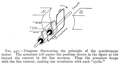 Fig. 447.—Diagram showing how the synchronous motor works. The armature coil reaches the position shown in the figure at the moment the current in the line reverses. As a result, the armature stays in sync with the line current, completing one full revolution with each "cycle."
445. A synchronous motor is one that keeps step with the alterations of an alternating current. The line current is fed into the armature by means of two slip rings and brushes. The principle of the synchronous motor is illustrated in Fig. 447. This shows a motor having a two-pole field. The armature current must be reversed[Pg 486] twice in each revolution. The reversal must take place when the armature winding is perpendicular to the lines of force of the field. In a direct current motor this reversal is brought about by the commutator. In a synchronous motor the armature reaches the 90 degree position at the exact instant at which the current reverses in the line. Thus in the case of a two-pole motor the armature must make exactly one revolution for each cycle; it is, therefore, a constant speed motor. Such motors are frequently employed in converter stations where alternating current is converted into direct current by what are called rotary converters.
445. A synchronous motor is one that stays in sync with the changes of an alternating current. The line current is supplied to the armature through two slip rings and brushes. The concept of the synchronous motor is shown in Fig. 447. This illustrates a motor with a two-pole field. The armature current must be reversed[Pg 486] twice during each rotation. The reversal should occur when the armature winding is perpendicular to the magnetic field lines. In a direct current motor, this reversal is done by the commutator. In a synchronous motor, the armature reaches the 90-degree position exactly when the current in the line reverses. Therefore, in the case of a two-pole motor, the armature must complete one full revolution for each cycle, making it a constant speed motor. These motors are commonly used in converter stations where alternating current is transformed into direct current by devices known as rotary converters.
In practice the synchronous motor has a number of pairs of field poles. It is essentially an alternating current generator running as a motor. One of the principal uses of the synchronous motor is that of a converter, receiving alternating current and delivering direct current. Synchronous motors are also used in transmission lines to aid in maintaining constant voltage.
In practice, the synchronous motor has several pairs of field poles. It essentially works like an alternating current generator functioning as a motor. One of the main uses of the synchronous motor is as a converter, taking in alternating current and providing direct current. Synchronous motors are also used in transmission lines to help keep the voltage stable.
Important Topics
The wireless telephone, essential parts, action, arrangement.
The cell phone, key components, function, setup.
Alternating currents, alternating fields.
AC, alternating fields.
Transformers, voltage relation of coils, power and core losses.
Transformers, the relationship between coil voltage, power losses, and core losses.
Self-induction, inductance, and coke coils, uses, applications.
Self-induction, inductance, and coke coils: uses and applications.
Impedance, reactance, and resistance; relation and effects.
Impedance, reactance, and resistance; their relationship and effects.
Condensers, uses and applications with a-c. circuits.
Condensers: uses and applications with alternating current (A.C.) circuits.
Alternating current power transmission; uses, advantages.
Alternating current power transmission: uses, benefits.
Power factor, lag, lead, volt-amperes, true watts.
Power factor, lag, lead, volt-amperes, real watts.
Single- and three-phase currents; uses and nature of each.
Single-phase and three-phase currents: their uses and characteristics.
Three-wire transmission systems, alternators, construction, and action.
Three-wire transmission systems, alternators, construction, and operation.
A-c. motors, series, induction, synchronous.
A-C motors: series, induction, synchronous.
INDEX
- Aberration, spherical, 408
- Absolute scale of temperature, 164
- Absorptions of gases by solids and liquids, 29
- Accelerated motion, 86
- Acceleration, 87
- Adhesion, 21
- Aeroplane, 97
- Air, aspirator, 67
- Alternators, 481
- Alternating current, 337, 466
- Amalgamation, 273
- Ammeter, 291
- Ampere, 291
- Archimedes' principle, 48
- Arc light, 321
- Armature, 335
- Artesian wells, 44
- Audion, 463
- Aurora borealis, 453
- Balloon, 72
- Barometer, 59
- Beats, 376
- Boiling, laws, 208
- point, 207
- Boyle's Law, 63
- Breezes, land and sea, 181
- British thermal unit, 162
- Brownian movements, 16
- Calorie, defined, 162
- Camera, 426
- Candlepower, 394
- Capillary action, 25
- Cartesian diver, 71
- Cathode rays, 453
- Centrifugal force, 91
- Charles' Law, 165
- Chladni's figures, 381
- Choke coils, 470
- Coefficient of expansion, definitions, 170
- Coherer, 449
- Cohesion, 21, 33
- Color, 435
- Commutator, 335, 336
- Compass, 230, 240
- Concave lens, 418
- Condenser, 260, 474
- Conductors, 246
- Conservation of energy, 127
- Continental code, 459
- compared with the Morse, 452
- Convection, 179
- Convex lens, 416
- Cooling, artificial, 210
- Corpuscular theory, 442
- Coulomb, 290
- meter, 291
- Couple, 101
- Critical angle, 414
- Crookes' tube, 456
- Crystallization, 28
- melting point of some crystalline substances, 203
- Daniel cell, 276
- Declination, 240
- Density, 38, 52
- methods for finding, 53
- Dew, 192
- Dew point, 193
- Diffusion of gases, 13
- Dipping needle, 240
- Direct Current, 337
- Dispersion, 433
- Distillation, 208
- Draft of a chimney, 180
- Dry cell, 275
- Dynamo, 330, 333
- Dyne, 93
- Eye, the, 423
- Ear, the, 386
- trumpet, 361
- Earth's magnetism, 238
- Echoes, 362
- Eclipses, 391
- Efficiency, 142
- Elasticity, 31
- Electric bell, 269, 287
- Electrical capacity, 259
- fields, 247
- Electrification, 243
- Electrolysis, 308
- Electromagnet, 281
- Electromagnetic theory of light, 456
- Electromotive force, 267
- unit of, 295
- Electron theory, 252
- Electrophorus, 263
- Electroplating, 307
- Electroscope, 244
- Electrostatic induction, 248
- Energy, 120
- Energy, kinetic, 121
- Engines, 213
- Engines, gas, 222
- Equilibrant, 81
- Equilibrium, 106
- Erg, 119
- Ether, 177
- Evaporation, 18
- Expansion, coefficient, 168
- Falling bodies, 109
- Floating bodies, 48
- Fluoroscope, 455
- Foot candle, 396
- Force, 79
- Forces, parallel, 100
- Franklin's theory of electricity, 252
- Fraunhofer lines, 439
- Freezing, evaporation, 197, 199
- mixtures, 210
- Friction, 147,
- Friction, laws, 150
- Galvanometers, 289
- Galvanoscope, 269
- Gas engine, 222
- efficiency of, 224
- Gas meter, 75
- Geissler tubes, 453
- Gravitation, 103
- law, 104
- Gravity, 88, 104
- Hail, 193
- Hearing, 386
- Heat, capacity for water, 201
- Heating of buildings, 182
- Hertzian waves, 262, 449
- Hooke's law, 33
- Horse power, 123
- electric equivalent of, 123
- Humidity, 194
- Hydraulic press, 42
- Hygrometers, 194
- Hygrometry, 191
- Hypothesis, 3
- Images, concave mirrors, 405
- Impedance, 472
- Incandescent lamp, 320
- Inclined plane, 143
- Inductance, 471
- Induction coil, 343
- Inertia, 87
- Insulators, 246
- Intensity of sound, 363
- Interference, light, 442
- sound, 374
- Laws, boiling, 208
- Boyle's 63
- Charles', 165
- electric action, 243
- falling bodies, 113
- floating bodies, 48
- gravitation, 104
- Hooke's, 33
- induced currents, 326
- intensity of light, 394
- Lenz's, 328
- liquid pressure, 37
- machines, 131
- magnetic action, 229
- motion, 87
- Ohm's, 298
- pendulum, 116
- reflection, 399
- refraction of light, 411
- vibration of strings, 378
- Lenses, achromatic, 434
- Leclanché cell, 275
- Lever, 132
- Leyden jar, 261
- oscillatory nature of the discharge, 448
- Light, compared with sound, 388, 444
- Lightning, 254
- Lines, of force, 233
- Liquids, pressure, 36
- Local action, 273
- Luminous and illuminated bodies, 388
- Machines, 129
- Magnetic action, 229
- Magnetism, 228
- Magnetism, theory, 232
- Major and minor triads, 369
- Magneto, 328
- Magnetoscope, 230
- Magnets, 228
- poles, 229
- Major scale, 366
- Manometric flames, 382
- Matter, 4
- Mechanical advantage, 134
- Megaphone, 365
- Melting points, 203
- Mercury arc rectifier, 347
- Metric system, 8
- Microscope, 427
- Mirage, 414
- Mirrors, 400
- Molecular motion in liquids, 18
- Molecules, motion, 16
- size, 13
- Moment of force, 99, 133
- Momentum, 87
- law of, 92
- Motion, 85
- Motor (electric), 339
- Muffler, 224
- Musical instruments, 377
- Musical sounds, characteristics 364
- Ohm, 294
- Ohm's Law, 298
- Opera glass, 428
- Optical illusions, 390, 404
- Organ pipes, closed, 384
- Oscillatory discharge, 448
- Osmosis, 19
- Outline Review,
- Overtones, 379
- Pascal's principle, 41
- Pendulum, compound, 115
- Pepper's ghost, 404
- Permeability, 237
- Phonograph, 383
- Physics, definition, 4
- Photometer, 394
- Photometry, 393
- Pitch, 365
- Polarization, of light, 445
- of voltaic cells, 273
- Portraits,
- Potential, 257
- Power, 123
- Pressure, air, 56
- atmospheric, 58
- Pressure, definition, 37
- Prism field glass, 429
- Projecting lantern, 427
- Proof-plane, 244
- Pulley, 139
- Pumps, air, 66
- Quality of musical tones, 380
- Radiation, 176
- sun's, 178
- Radio-activity, 457
- Radiometer, 177
- Radium, 457
- Rainbow, 436
- Reactance, 472
- Reflection, light, 396
- Refraction, 410
- Resolution of forces, 96
- Resistance, cells in series, and parallel, 302
- Resonance, 371
- Resonator, 373
- Resultant, 81
- Retentivity, 231
- Right hand rule, 279
- Rotary converter, 486
- Science, definition, 2
- Screw, 144
- Shadows, 390
- Single phase currents, 479
- Siphon, 70
- Siren, 366
- Solidification, change of volume during, 203
- Solutions, 27
- Sound, compared with light, 388
- Specific heat, 200
- method of determining, 201
- Spectroscope, 438
- Spectrum, 433
- Spherical aberration, 408
- Spinthariscope, 458
- Stability, 108
- Standpipe, 46
- Static and current electricity compared, 287
- electrical machines, 262
- Steam engine, 213
- turbine, 225
- Storage battery, 312
- Stress and strain, 94
- Sublimation, 199
- Surface tension, 22
- Sympathetic vibration, 372
- Telegraph, 283
- wireless, 450
- Telephone, 349
- Telescope, 428
- Temperature, 162
- absolute scale, 164
- Tempered scale, 370
- Theory, 3
- Thermometer, air, 167
- Thermos bottle, 176
- Thermostat, 188
- Three-color printing, 440
- Three-phase currents, 479
- Three wire transmission, 480
- Torricelli's experiment, 57
- Trade winds, 182
- Transformer, 345, 467
- uses, 347
- Turbine, steam, 225
- water, 154
- Vacuum cleaner, 76
- pan, 210
- Velocity, 86
- Vibration strings, 378
- sympathetic, 372
- Visual angle, 424
- Viscosity, 20
- Volt, 295
- Voltaic cell, 270
- Voltmeter, 295
- Water wheels, 152
- Watt, 123, 317
- Wave theory, of light, 442
- Waves, beats, 376
- Wedge, 144
- Weight, 104
- Wheatstone bridge, 304
- Wheel and axle, 136
- Wind instruments, 383
- Wireless telegraphy, 450
- telephony, 460
- Work, 119
- units, 119
- "X" rays 454
FOOTNOTES:
[J] American League of Automobile Manufacturers.
__A_TAG_PLACEHOLDER_0__ American League of Auto Makers.
[K] Many scientists consider that current in a conductor consists of negative electrons flowing in a direction opposite to that described in Art. 243. This is called the electron current, as distinguished from the electric current described above.
[K] Many scientists believe that the current in a conductor is made up of negative electrons moving in a direction opposite to what is outlined in Art. 243. This is referred to as the electron current, in contrast to the electric current mentioned earlier.
Transcriber's note:
This book uses B.T.U. and B.t.u., electrophorous and electrophorus,
e.m.f. and E.M.F. and this has been left as written.
Hyphenation is also left as written, e.g. electro-plated and
electroplated.
On page 324, Exercise number 8 was not used in the original. The
exercises have not been renumbered.
Transcription note:
This book uses B.T.U. and B.t.u., electrophorous and electrophorus, e.m.f. and E.M.F. and this has been left as is.
Hyphenation is also left as is, e.g. electro-plated and electroplated.
On page 324, Exercise number 8 was not included in the original. The exercises have not been renumbered.
Download ePUB
If you like this ebook, consider a donation!