This is a modern-English version of Encyclopaedia Britannica, 11th Edition, "Lightfoot, Joseph" to "Liquidation": Volume 16, Slice 6, originally written by Various.
It has been thoroughly updated, including changes to sentence structure, words, spelling,
and grammar—to ensure clarity for contemporary readers, while preserving the original spirit and nuance. If
you click on a paragraph, you will see the original text that we modified, and you can toggle between the two versions.
Scroll to the bottom of this page and you will find a free ePUB download link for this book.
| Transcriber’s note: |
A few typographical errors have been corrected. They
appear in the text like this, and the
explanation will appear when the mouse pointer is moved over the marked
passage. Sections in Greek will yield a transliteration
when the pointer is moved over them, and words using diacritic characters in the
Latin Extended Additional block, which may not display in some fonts or browsers, will
display an unaccented version. Links to other EB articles: Links to articles residing in other EB volumes will be made available when the respective volumes are introduced online. |
THE ENCYCLOPÆDIA BRITANNICA
A DICTIONARY OF ARTS, SCIENCES, LITERATURE AND GENERAL INFORMATION
ELEVENTH EDITION
VOLUME XVI SLICE VI
Lightfoot, Joseph to Liquidation
Articles in This Slice
Articles in This Section

LIGHTFOOT, JOSEPH BARBER (1828-1889), English theologian and bishop of Durham, was born at Liverpool on the 13th of April 1828. His father was a Liverpool accountant. He was educated at King Edward’s school, Birmingham, under James Prince Lee, afterwards bishop of Manchester, and had as contemporaries B. F. Westcott and E. W. Benson. In 1847 Lightfoot went up to Trinity College, Cambridge, and there read for his degree with Westcott. He graduated senior classic and 30th wrangler, and was elected a fellow of his college. From 1854 to 1859 he edited the Journal of Classical and Sacred Philology. In 1857 he became tutor and his fame as a scholar grew rapidly. He was made Hulsean professor in 1861, and shortly afterwards chaplain to the Prince Consort and honorary chaplain in ordinary to the queen. In 1866 he was Whitehall 627 preacher, and in 1871 he became canon of St Paul’s. His sermons were not remarkable for eloquence, but a certain solidity and balance of judgment, an absence of partisanship, a sobriety of expression combined with clearness and force of diction, attracted hearers and inspired them with confidence. As was written of him in The Times after his death, “his personal character carried immense weight, but his great position depended still more on the universally recognized fact that his belief in Christian truth and his defence of it were supported by learning as solid and comprehensive as could be found anywhere in Europe, and by a temper not only of the utmost candour but of the highest scientific capacity. The days in which his university influence was asserted were a time of much shaking of old beliefs. The disintegrating speculations of an influential school of criticism in Germany were making their way among English men of culture just about the time, as is usually the case, when the tide was turning against them in their own country. The peculiar service which was rendered at this juncture by the ‘Cambridge School’ was that, instead of opposing a mere dogmatic opposition to the Tübingen critics, they met them frankly on their own ground; and instead of arguing that their conclusions ought not to be and could not be true, they simply proved that their facts and their premisses were wrong. It was a characteristic of equal importance that Dr Lightfoot, like Dr Westcott, never discussed these subjects in the mere spirit of controversy. It was always patent that what he was chiefly concerned with was the substance and the life of Christian truth, and that his whole energies were employed in this inquiry because his whole heart was engaged in the truths and facts which were at stake. He was not diverted by controversy to side-issues; and his labour was devoted to the positive elucidation of the sacred documents in which the Christian truth is enshrined.”
LIGHTFOOT, JOSEPH BARBER (1828-1889), an English theologian and bishop of Durham, was born in Liverpool on April 13, 1828. His father was an accountant in Liverpool. He was educated at King Edward’s School in Birmingham under James Prince Lee, who later became bishop of Manchester, and he was contemporaries with B. F. Westcott and E. W. Benson. In 1847, Lightfoot attended Trinity College, Cambridge, where he studied for his degree alongside Westcott. He graduated as the senior classic and 30th wrangler, and was elected a fellow of his college. From 1854 to 1859, he edited the Journal of Classical and Sacred Philology. In 1857, he became a tutor, and his reputation as a scholar grew quickly. He was appointed Hulsean professor in 1861, and soon after became chaplain to the Prince Consort and honorary chaplain in ordinary to the queen. In 1866, he was a Whitehall preacher, and in 1871 he became canon of St Paul’s. His sermons weren’t known for their eloquence, but rather for a solid and balanced judgment, an absence of partisanship, and a sober yet clear and forceful manner of speaking, which attracted listeners and inspired their confidence. As noted in The Times after his death, “his personal character carried immense weight, but his significant standing relied even more on the widely acknowledged fact that his belief in Christian truth and his defense of it were backed by a learning as solid and comprehensive as could be found anywhere in Europe, along with a temperament that was not only extremely candid but of the highest scientific capability. The period during which his influence at the university emerged was marked by much upheaval of old beliefs. The disruptive theories from a prominent school of criticism in Germany were gaining traction among cultured Englishmen just as the tide was turning against them in their own country. The unique contribution made by the ‘Cambridge School’ at this time was that, instead of simply opposing the Tübingen critics dogmatically, they confronted them directly on their own terms; and instead of arguing that their conclusions shouldn't and couldn't be true, they simply demonstrated that their facts and premises were incorrect. It was also notable that Dr. Lightfoot, like Dr. Westcott, never approached these issues with a mere spirit of controversy. It was always clear that what mattered most to him was the essence and life of Christian truth, and that all his efforts were focused on this inquiry because his heart was fully engaged with the truths and facts at stake. He wasn’t sidetracked by controversy or side-issues; his work was dedicated to the positive clarification of the sacred texts in which the Christian truth is enshrined.”
In 1872 the anonymous publication of Supernatural Religion created considerable sensation. In a series of masterly papers in the Contemporary Review, between December 1874 and May 1877, Lightfoot successfully undertook the defence of the New Testament canon. The articles were published in collected form in 1889. About the same time he was engaged in contributions to W. Smith’s Dictionary of Christian Biography and Dictionary of the Bible, and he also joined the committee for revising the translation of the New Testament. In 1875 he became Lady Margaret professor of divinity in succession to William Selwyn. He had previously written his commentaries on the epistles to the Galatians (1865), Philippians (1868) and Colossians (1875), the notes to which were distinguished by sound judgment and enriched from his large store of patristic and classical learning. These commentaries may be described as to a certain extent a new departure in New Testament exegesis. Before Lightfoot’s time commentaries, especially on the epistles, had not infrequently consisted either of short homilies on particular portions of the text, or of endeavours to enforce foregone conclusions, or of attempts to decide with infinite industry and ingenuity between the interpretations of former commentators. Lightfoot, on the contrary, endeavoured to make his author interpret himself, and by considering the general drift of his argument to discover his meaning where it appeared doubtful. Thus he was able often to recover the meaning of a passage which had long been buried under a heap of contradictory glosses, and he founded a school in which sobriety and common sense were added to the industry and ingenuity of former commentators. In 1879 Lightfoot was consecrated bishop of Durham in succession to C. Baring. His moderation, good sense, wisdom, temper, firmness and erudition made him as successful in this position as he had been when professor of theology, and he speedily surrounded himself with a band of scholarly young men. He endeavoured to combine his habits of theological study with the practical work of administration. He exercised a large liberality and did much to further the work of temperance and purity organizations. He continued to work at his editions of the Apostolic Fathers, and in 1885 published an edition of the Epistles of Ignatius and Polycarp, collecting also a large store of valuable materials for a second edition of Clement of Rome, which was published after his death (1st ed., 1869). His defence of the authenticity of the Epistles of Ignatius is one of the most important contributions to that very difficult controversy. His unremitting labours impaired his health and shortened his splendid career at Durham. He was never married. He died at Bournemouth on the 21st of December 1889, and was succeeded in the episcopate by Westcott, his schoolfellow and lifelong friend.
In 1872, the anonymous release of Supernatural Religion caused quite a stir. In a series of impressive articles in the Contemporary Review from December 1874 to May 1877, Lightfoot effectively defended the New Testament canon. These articles were compiled into a book published in 1889. Around the same time, he contributed to W. Smith's Dictionary of Christian Biography and Dictionary of the Bible, and he also participated in the committee to revise the New Testament translation. In 1875, he became the Lady Margaret professor of divinity, succeeding William Selwyn. He had previously written commentaries on the letters to the Galatians (1865), Philippians (1868), and Colossians (1875), noted for their sound judgment and enriched by his extensive knowledge of early church and classical texts. These commentaries marked a somewhat new approach to New Testament interpretation. Before Lightfoot, commentaries, particularly on the epistles, often consisted of brief sermons on specific passages, attempts to support predetermined conclusions, or extensive debates over the interpretations of earlier commentators. In contrast, Lightfoot aimed to let the text speak for itself, focusing on the overall direction of the argument to clarify its meaning when it seemed unclear. This allowed him frequently to unveil the meaning of passages that had been obscured by a multitude of conflicting interpretations, establishing a scholarly approach that combined careful analysis and common sense with the diligence and creativity of earlier scholars. In 1879, Lightfoot was consecrated as the bishop of Durham, succeeding C. Baring. His moderation, practical wisdom, temperament, firmness, and scholarship made him just as effective in this role as he had been as a theology professor, and he quickly surrounded himself with a group of scholarly young men. He sought to balance his theological studies with the practical aspects of administration. He displayed a great deal of generosity and worked significantly to promote temperance and purity initiatives. He continued refining his editions of the Apostolic Fathers, and in 1885, he published an edition of the Epistles of Ignatius and Polycarp, while also gathering valuable resources for a second edition of Clement of Rome, which was published after his death (1st ed., 1869). His defense of the authenticity of the Epistles of Ignatius is among the most significant contributions to that intricate debate. His tireless efforts took a toll on his health and curtailed his remarkable career at Durham. He never married. He passed away in Bournemouth on December 21, 1889, and was succeeded as bishop by Westcott, his school friend and lifelong companion.
Four volumes of his Sermons were published in 1890.
Four volumes of his Sermons were published in 1890.
1. Early History.—The earliest lighthouses, of which records exist, were the towers built by the Libyans and Cushites in Lower Egypt, beacon fires being maintained in some of them by the priests. Lesches, a Greek poet (c. 660 B.C.) mentions a lighthouse at Sigeum (now Cape Incihisari) in the Troad. This appears to have been the first light regularly maintained for the guidance of mariners. The famous Pharos1 of Alexandria, built by Sostratus of Cnidus in the reign of Ptolemy II. (283-247 B.C.) was regarded as one of the wonders of the world. The tower, which took its name from that of the small island on which it was built, is said to have been 600 ft. in height, but the evidence in support of this statement is doubtful. It was destroyed by an earthquake in the 13th century, but remains are said to have been visible as late as 1350. The name Pharos became the general term for all lighthouses, and the term “pharology” has been used for the science of lighthouse construction.
1. Early History.—The earliest lighthouses we have records of were the towers built by the Libyans and Cushites in Lower Egypt, where priests maintained beacon fires in some of them. Lesches, a Greek poet (c. 660 B.C.), mentions a lighthouse at Sigeum (now Cape Incihisari) in the Troad. This seems to be the first light regularly kept for guiding sailors. The famous Pharos1 of Alexandria, built by Sostratus of Cnidus during the reign of Ptolemy II. (283-247 B.C.), was considered one of the wonders of the world. The tower, named after the small island it was constructed on, is said to have been 600 ft. tall, though there is some doubt about this claim. It was destroyed by an earthquake in the 13th century, but remains were reportedly visible as late as 1350. The name Pharos became the general term for all lighthouses, and the term “pharology” has been adopted for the study of lighthouse construction.
The tower at Ostia was built by the emperor Claudius (A.D. 50). Other famous Roman lighthouses were those at Ravenna, Pozzuoli and Messina. The ancient Pharos at Dover and that at Boulogne, later known as la Tour d’Ordre, were built by the Romans and were probably the earliest lighthouses erected in western Europe. Both are now demolished.
The tower at Ostia was built by Emperor Claudius (A.D. 50). Other well-known Roman lighthouses were located at Ravenna, Pozzuoli, and Messina. The ancient Pharos at Dover and the one at Boulogne, later known as la Tour d’Ordre, were built by the Romans and were likely the first lighthouses constructed in Western Europe. Both have now been demolished.
The light of Cordouan, on a rock in the sea at the mouth of the Gironde, is the earliest example now existing of a wave-swept tower. Earlier towers on the same rock are attributed the first to Louis le Debonnaire (c. A.D. 805) and the second to Edward the Black Prince. The existing structure was begun in 1584 during the reign of Henri II. of France and completed in 1611. The upper part of the beautiful Renaissance building was removed towards the end of the 18th century and replaced by a loftier cylindrical structure rising to a height of 207 ft. above the rock and with the focal plane of the light 196 ft. above high water (fig. 1). Until the 18th century the light exhibited from the tower was from an oak log fire, and subsequently a coal fire was in use for many years. The ancient tower at Corunna, known as the Pillar of Hercules, is supposed to have been a Roman Pharos. The Torre del Capo at Genoa originally stood on the promontory of San Berrique. It was built in 1139 and first used as a lighthouse in 1326. It was rebuilt on its present site in 1643. This beautiful tower rises 236 ft. above the cliff, the light being elevated 384 ft. above sea-level. A lens light was first installed in 1841. The Pharos of Meloria was constructed by the Pisans in 1154 and was several times rebuilt until finally destroyed in 1290. On the abandonment of Meloria by the Pisans, they erected the still existing tower at Leghorn in 1304.
The light of Cordouan, located on a rock in the sea at the mouth of the Gironde, is the earliest surviving example of a wave-swept tower. Earlier towers on the same rock are credited to Louis the Pious (around A.D. 805) and Edward the Black Prince. The current structure began construction in 1584 during the reign of Henri II of France and was completed in 1611. The upper part of the beautiful Renaissance building was removed in the late 18th century and replaced with a taller cylindrical structure that rises to a height of 207 ft. above the rock, with the focal point of the light 196 ft. above high water (fig. 1). Until the 18th century, the light emitted from the tower was produced by an oak log fire, and later, a coal fire was used for many years. The ancient tower at Corunna, known as the Pillar of Hercules, is believed to have been a Roman lighthouse. The Torre del Capo in Genoa originally stood on the promontory of San Berrique. It was built in 1139 and first used as a lighthouse in 1326. It was rebuilt at its current location in 1643. This stunning tower rises 236 ft. above the cliff, with the light situated 384 ft. above sea level. A lens light was first installed in 1841. The Pharos of Meloria was built by the Pisans in 1154 and was rebuilt several times before being finally destroyed in 1290. After the Pisans abandoned Meloria, they constructed the still-standing tower at Leghorn in 1304.
In the 17th and 18th centuries numerous towers, on which were erected braziers or grates containing wood or coal fires, were established in various positions on the coasts of Europe. Among such stations in the United Kingdom were Tynemouth (c. 1608), the Isle of May (1636), St Agnes (1680), St Bees (1718) and the Lizard (1751). The oldest lighthouse in the United States is believed to be the Boston light situated on Little Brewster Island on the south side of the main entrance to Boston Harbour, Mass. It was established in 1716, the present structure dating from 1859. During the American War of Independence the lighthouse suffered many vicissitudes and was successively destroyed and rebuilt three times by the American or British 628 forces. At the third rebuilding in 1783 a stone tower 68 ft. in height was erected, the illuminant consisting of four oil lamps. Other early lighthouse structures on the New England coast were those at Beaver Tail, near the entrance to Newport Harbour (1740), and the Brant at the entrance to Nantucket Harbour (1754). A watch-house and beacon appear to have been erected on Beacon or Lighthouse Island as well as on Point Allerton Hill near Boston, prior to 1673, but these structures would seem to have been in the nature of look-out stations in time of war rather than lighthouses for the guidance of mariners.
In the 17th and 18th centuries, many towers with braziers or grates for wood or coal fires were established along the coasts of Europe. Some of these stations in the United Kingdom included Tynemouth (ca. 1608), the Isle of May (1636), St Agnes (1680), St Bees (1718), and the Lizard (1751). The oldest lighthouse in the United States is thought to be the Boston light, located on Little Brewster Island at the south entrance of Boston Harbour, Massachusetts. It was established in 1716, with the current structure dating from 1859. During the American War of Independence, the lighthouse went through many ups and downs, being destroyed and rebuilt three times by either American or British forces. The third rebuilding in 1783 resulted in a stone tower that is 68 ft. high, with four oil lamps serving as the light source. Other early lighthouse structures along the New England coast included Beaver Tail, near the entrance to Newport Harbour (1740), and the Brant at the entrance to Nantucket Harbour (1754). A watch-house and beacon seem to have been built on Beacon or Lighthouse Island and on Point Allerton Hill near Boston before 1673, but these structures were likely lookout stations for wartime rather than lighthouses to guide sailors.
2. Lighthouse Structures.—The structures of lighthouses may be divided into two classes, (a) those on rocks, shoals or in other situations exposed to the force of the sea, and (b) the more numerous class of land structures.
2. Lighthouse Designs.—Lighthouse structures can be categorized into two types, (a) those built on rocks, shoals, or other areas exposed to the sea's force, and (b) the more common type of land-based structures.
 |
| Fig. 1.—Cordouan Lighthouse. |
Wave-swept Towers.—In determining the design of a lighthouse tower to be erected in a wave-swept position consideration must be given to the physical features of the site and its surroundings. Towers of this description are classified as follows: (1) Masonry and concrete structures; (2) Openwork steel and iron-framed erections on pile or other foundations; (3) Cast iron plated towers; (4) Structures erected on cylinder foundations.
Wave-swept Towers.—When designing a lighthouse tower to be built in a wave-swept location, it’s important to consider the physical characteristics of the site and its surroundings. Towers of this type are categorized as follows: (1) Masonry and concrete structures; (2) Openwork steel and iron-framed constructions on pile or other foundations; (3) Cast iron plated towers; (4) Structures built on cylinder foundations.
(1) Masonry Towers.—Masonry or concrete towers are generally preferred for erection on wave-swept rocks affording good foundation, and have also been constructed in other situations where adequate foundations have been made by sinking caissons into a soft sea bed. Smeaton’s tower on the Eddystone Rock is the model upon which most later designs of masonry towers have been based, although many improvements in detail have since been made. In situations of great exposure the following requirements in design should be observed: (a) The centre of gravity of the tower structure should be as low as possible. (b) The mass of the structure superimposed at any horizontal section must be sufficient to prevent its displacement by the combined forces of wind and waves without dependence on the adhesion at horizontal joint faces or on the dovetailing of stones introduced as an additional safeguard. (c) The structure should be circular in plan throughout, this form affording the least resistance to wave stroke and wind pressure in any direction. (d) The lower portion of the tower exposed to the direct horizontal stroke of the waves should, for preference, be constructed with vertical face. The upper portion to be either straight with uniform batter or continuously curved in the vertical plane. External projections from the face of the tower, except in the case of a gallery under the lantern, should be avoided, the surface throughout being smooth. (e) The height from sea-level to the top of the tower should be sufficient to avoid the obscuration of the light by broken water or dense spray driving over the lantern. (f) The foundation of the tower should be carried well into the solid rock. (g) The materials of which the tower is built should be of high density and of resistant nature. (h) The stones used in the construction of the tower, at any rate those on the outer face, should be dovetailed or joggled one to the other in order to prevent their being dislodged by the sea during the process of construction and as an additional safeguard of stability. Of late years, cement concrete has been used to a considerable extent for maritime structures, including lighthouses, either alone or faced with masonry.
(1) Masonry Towers.—Masonry or concrete towers are usually the preferred choice for building on wave-swept rocks that provide a solid foundation. They’ve also been constructed in other places where solid foundations have been created by sinking caissons into a soft seabed. Smeaton’s tower on Eddystone Rock serves as the model for most later masonry tower designs, although many details have been improved since then. In sites with significant exposure, the following design requirements should be met: (a) The center of gravity of the tower should be as low as possible. (b) The mass of the structure at any horizontal section must be enough to prevent it from being displaced by the combined forces of wind and waves, without relying on the adhesion at horizontal joint faces or on the dovetailing of stones as an extra safeguard. (c) The structure should be circular in shape throughout, as this shape offers the least resistance to wave action and wind pressure from any direction. (d) The lower part of the tower that faces direct horizontal wave impact should ideally be built with a vertical face. The upper part should either be straight with a consistent slope or continuously curved in the vertical plane. Any external projections from the face of the tower, except for a gallery under the lantern, should be avoided, keeping the surface smooth throughout. (e) The height from sea level to the top of the tower should be enough to prevent the light from being obscured by breaking waves or heavy spray hitting the lantern. (f) The tower’s foundation should extend well into solid rock. (g) The materials used to build the tower should be high-density and durable. (h) The stones used in the tower's construction, especially those on the outer face, should be dovetailed or interlocked with each other to prevent being dislodged by the sea during construction and to provide an additional stability safeguard. Recently, cement concrete has been widely used for maritime structures, including lighthouses, either on its own or faced with masonry.
(2) Openwork Structures.—Many examples of openwork steel and iron lighthouses exist. Some typical examples are described hereafter. This form of design is suitable for situations where the tower has to be carried on a foundation of iron or steel piles driven or screwed into an insecure or sandy bottom, such as on shoals, coral reefs and sand banks or in places where other materials of construction are exceptionally costly and where facility of erection is a desideratum.
(2) Openwork Structures.—There are many examples of openwork steel and iron lighthouses. Some typical examples are described below. This design is suitable for situations where the tower needs to be supported on foundations made of iron or steel piles that are driven or screwed into unstable or sandy ground, such as on shoals, coral reefs, and sandbanks, or in areas where other construction materials are particularly expensive and ease of assembly is a priority.
(3) Cast iron Towers.—Cast iron plated towers have been erected in many situations where the cost of stone or scarcity of labour would have made the erection of a masonry tower excessively expensive.
(3) Cast Iron Towers.—Cast iron towers have been built in many places where the cost of stone or lack of labor would have made constructing a brick or stone tower way too expensive.
(4) Caisson Foundations.—Cylinder or caisson foundations have been used for lighthouse towers in numerous cases where such structures have been erected on sand banks or shoals. A remarkable instance is the Rothersand Tower. Two attempts have been made to sink a caisson in the outer Diamond Shoal off Cape Hatteras on the Atlantic coast of the United States, but these have proved futile.
(4) Caisson Foundations.—Caisson foundations have been used for lighthouse towers in many cases where these structures were built on sandbanks or shallow areas. A notable example is the Rothersand Tower. There have been two attempts to sink a caisson in the outer Diamond Shoal off Cape Hatteras on the Atlantic coast of the United States, but both have been unsuccessful.
The following are brief descriptions of the more important wave-swept towers in various parts of the world.
The following are short descriptions of the more significant wave-swept towers in different parts of the world.
Eddystone (Winstanley’s Tower).—The Eddystone rocks, which lie about 14 m. off Plymouth, are fully exposed to south-west seas. The reef is submerged at high water of spring tides. Four towers have been constructed on the reef. The first lighthouse (fig. 2) was polygonal in plan and highly ornamented with galleries and projections which offered considerable resistance to the sea stroke. The work was begun by Henry Winstanley, a gentleman of Essex, in 1695. In 1698 it was finished to a height of 80 ft. to the wind vane and the light exhibited, but in the following year, in consequence of damage by storms, the tower was increased in diameter from 16 ft. to 24 ft. by the addition of an outer ring of masonry and made solid to a height of 20 ft. above the rock, the tower being raised to nearly 120 ft. The work was completed in the year 1700. The lower part of the structure appears to have been of stone, the upper part and lantern of timber. During the great storm of the 20th of November 1703 the tower was swept away, those in it at the time, including the builder, being drowned.
Eddystone (Winstanley’s Tower).—The Eddystone rocks, located about 14 miles off Plymouth, are fully exposed to the south-western seas. The reef is underwater during high spring tides. Four towers have been built on the reef. The first lighthouse (fig. 2) had a polygonal design and was highly decorated with galleries and projections that provided considerable resistance to wave impact. The project was started by Henry Winstanley, a gentleman from Essex, in 1695. By 1698, it was completed to a height of 80 feet up to the wind vane and the light was operational. However, in the following year, due to storm damage, the tower's diameter was increased from 16 feet to 24 feet with the addition of an outer ring of masonry, and it was made solid up to 20 feet above the rock, raising the tower to nearly 120 feet. The work was finished in 1700. The lower part of the structure was made of stone, while the upper part and lantern were made of timber. During the great storm on November 20, 1703, the tower was destroyed, and those inside at the time, including the builder, drowned.
Eddystone (Rudyerd’s Tower, fig. 3).—This structure was begun in 1706 and completed in 1709. It was a frustum of a cone 22 ft. 8 in. in diameter at the base and 14 ft. 3 in. at the top. The tower was 92 ft. in height to the top of the lantern. The work consisted principally of oak timbers securely bolted and cramped together, the lower part being filled in solid with stone to add weight to the structure. The simplicity of the design and the absence of projections from the outer face rendered the tower very suitable to withstand the onslaught of the waves. The lighthouse was destroyed by fire in 1755.
Eddystone (Rudyerd’s Tower, fig. 3).—This structure was started in 1706 and finished in 1709. It was a frustum of a cone measuring 22 ft. 8 in. in diameter at the bottom and 14 ft. 3 in. at the top. The tower stood 92 ft. tall to the top of the lantern. The construction mainly consisted of oak timbers securely bolted and fastened together, with the lower part filled in solid with stone to add weight to the structure. The simple design and lack of protrusions from the outer surface made the tower very capable of withstanding the force of the waves. The lighthouse was destroyed by fire in 1755.
Eddystone (Smeaton’s Tower, fig. 4).—This famous work, which consisted entirely of stone, was begun in 1756, the light being first exhibited in 1759. John Smeaton was the first engineer to use dovetailed joints for the stones in a lighthouse structure. The stones, which averaged 1 ton in weight, were fastened to each other by means of dovetailed vertical joint faces, oak key wedges, and by oak tree-nails wedged top and bottom, extending vertically from every course into the stones beneath it. During the 19th century the tower was strengthened on two occasions by the addition of heavy wrought iron ties, and the overhanging cornice was reduced in diameter to prevent the waves from lifting the stones from their beds. In 1877, owing partly to the undermining of the rock on which the tower was built and the insufficient height of the structure, 629 the Corporation of Trinity House determined on the erection of a new lighthouse in place of Smeaton’s tower.
Eddystone (Smeaton’s Tower, fig. 4).—This iconic structure, built entirely of stone, started construction in 1756, and the light was first turned on in 1759. John Smeaton was the first engineer to use dovetailed joints to connect the stones in a lighthouse. The stones, averaging 1 ton each, were secured together using dovetailed vertical joint faces, oak key wedges, and oak tree-nails that were wedged in from the top and bottom, extending vertically into the stones below. In the 19th century, the tower was reinforced twice with heavy wrought iron ties, and the overhanging cornice was made smaller to stop waves from dislodging the stones. In 1877, due in part to the erosion of the rock underneath the tower and the building's inadequate height, 629 the Corporation of Trinity House decided to build a new lighthouse to replace Smeaton’s tower.
 | |||
| Fig. 2. | Fig. 3. | Fig. 4. | Fig. 5. |
| Lighthouses on the Eddystone. | |||
 |
| Fig. 6.—Plan of Entrance Floor, Eddystone Lighthouse. |
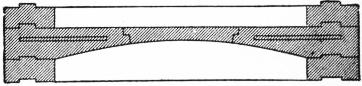
Eddystone, New Lighthouse (J. N. Douglass).—The site selected for the new tower is 120 ft. S.S.E. from Smeaton’s lighthouse, where a suitable foundation was found, although a considerable section of the lower courses had to be laid below the level of low water. The vertical base is 44 ft. in diameter and 22 ft. in height. The tower (figs. 5 and 6) is a concave elliptic frustum, and is solid, with the exception of a fresh-water tank, to a height of 25 ft. 6 in. above high-water level. The walls above this level vary in thickness from 8 ft. 6 in. to 2 ft. 3 in. under the gallery. All the stones are dovetailed, both horizontally and vertically, on all joint faces, the stones of the foundation course being secured to the rock by Muntz metal bolts. The tower contains 62,133 cub. ft. of granite, weighing 4668 tons. The height of the structure from low water ordinary spring tides to the mean focal plane is 149 ft. and it stands 133 ft. above high water. The lantern is a cylindrical helically framed structure with domed roof. The astragals are of gun-metal and the pedestal of cast iron. The optical apparatus consists of two superposed tiers of refracting lens panels, 12 in each tier of 920 mm. focal distance. The lenses subtend an angle of 92° vertically. The 12 lens panels are arranged in groups of two, thus producing a group flashing light showing 2 flashes of 1½ seconds’ duration every half minute, the apparatus revolving once in 3 minutes. The burners originally fitted in the apparatus were of 6-wick pattern, but these were replaced in 1904 by incandescent oil vapour burners. The intensity of the combined beam of light from the two apparatus is 292,000 candles. At the time of the completion of the lighthouse two bells, weighing 2 tons each and struck by mechanical power, were installed for fog-signalling purposes. Since that date an explosive gun-cotton fog signal has been erected, the bells being removed. At a lower level in the tower are installed 2 21-in. parabolic silvered reflectors with 2-wick burners, throwing a fixed light of 8000 candle-power over a danger known as the Hand Deeps. The work of preparing the foundation was begun on the 17th of July 1878, the foundation stone being laid by the late duke of Edinburgh on the 19th of August 1879. The last stone was laid on the 1st of June 1881, and the light was exhibited for the first time on the 18th of May 1882. The upper portion of Smeaton’s tower, which was removed on completion of the new lighthouse, was re-erected on Plymouth Hoe, where it replaced the old Trinity House sea mark. One of the principal features in the design of the new Eddystone lighthouse tower is the solid vertical base. This construction was much criticized at the time, but experience has proved that heavy seas striking the massive cylindrical structure are immediately broken up and rush round to the opposite side, spray alone ascending to the height of the lantern gallery. On the other hand, the waves striking the old tower at its foundation ran up the surface, which presented a curved face to the waves, and, unimpeded by any projection until arriving at the lantern gallery, were partially broken up by the cornice and then spent themselves in heavy spray over the lantern. The shock to which the cornice of the gallery was exposed was so great that stones were sometimes lifted from their beds. The new Eddystone tower presents another point of dissimilarity from Smeaton’s structure, in that the stones forming the floors consist of single corbels built into the wall and constituting solid portions thereof. In Smeaton’s tower the floors consisted of stone arches, the thrust being taken by the walls of the tower itself, which were strengthened for the purpose by building in chains in the form of hoops (fig. 7). The system of constructing corbelled stone floors was first adopted by R. Stevenson in the Bell Rock lighthouse (fig. 8).
Eddystone, New Lighthouse (J. N. Douglass).—The location chosen for the new tower is 120 ft. S.S.E. from Smeaton’s lighthouse, where a suitable foundation was discovered, though a significant section of the lower courses had to be placed below the low water level. The vertical base measures 44 ft. in diameter and 22 ft. in height. The tower (figs. 5 and 6) is a concave elliptical frustum and is solid, except for a fresh-water tank, up to a height of 25 ft. 6 in. above high-water level. The walls above this point vary in thickness from 8 ft. 6 in. to 2 ft. 3 in. below the gallery. All the stones are dovetailed both horizontally and vertically on all joint faces, and the stones of the foundation course are secured to the rock with Muntz metal bolts. The tower contains 62,133 cubic feet of granite, weighing 4,668 tons. The height of the structure from the low water of ordinary spring tides to the mean focal plane is 149 ft., standing 133 ft. above high water. The lantern is a cylindrical structure with a domed roof. The astragals are made of gun-metal, and the pedestal is made of cast iron. The optical system consists of two stacked tiers of refracting lens panels, with 12 in each tier at a focal distance of 920 mm. The lenses cover an angle of 92° vertically. The 12 lens panels are grouped in pairs, creating a flashing light that shows 2 flashes lasting 1.5 seconds every half minute, with the apparatus rotating every 3 minutes. The original burners used a 6-wick pattern, but these were replaced in 1904 with incandescent oil vapor burners. The intensity of the combined beam from the two systems is 292,000 candles. When the lighthouse was completed, two bells, each weighing 2 tons and struck by mechanical power, were installed for fog signaling. Since then, an explosive gun-cotton fog signal has been set up, and the bells were removed. At a lower level in the tower, there are 2 21-in. parabolic silvered reflectors with 2-wick burners, producing a fixed light of 8,000 candle-power over a danger known as the Hand Deeps. Work on the foundation began on July 17, 1878, with the foundation stone laid by the late Duke of Edinburgh on August 19, 1879. The last stone was placed on June 1, 1881, and the light was first lit on May 18, 1882. The upper portion of Smeaton’s tower, which was taken down upon completion of the new lighthouse, was re-erected on Plymouth Hoe, replacing the old Trinity House sea mark. One of the main features of the new Eddystone lighthouse tower is its solid vertical base. This design faced much criticism at the time, but experience has shown that heavy seas hitting the massive cylindrical structure are quickly broken up and redirected to the opposite side, with only spray reaching the height of the lantern gallery. In contrast, waves hitting the old tower at its foundation climbed along a curved surface and, unhampered until reaching the lantern gallery, were partially disrupted by the cornice and then unleashed as heavy spray over the lantern. The impact on the cornice of the gallery was so intense that stones were occasionally dislodged. The new Eddystone tower also differs from Smeaton’s structure by having floors made of single corbels integrated into the walls, forming solid portions thereof. In Smeaton’s tower, the floors were made of stone arches, with the thrust supported by the walls, which were reinforced with chains shaped like hoops (fig. 7). The method of building corbelled stone floors was first introduced by R. Stevenson in the Bell Rock lighthouse (fig. 8).
 |
| Fig. 7.—Floor, Smeaton’s Eddystone Lighthouse. |
Bell Rock Lighthouse (fig. 9).—The Bell Rock, which lies 12 m. off the coast of Forfarshire, is exposed to a considerable extent at low water. The tower is submerged to a depth of about 16 ft. at high water of spring tides. The rock is of hard sandstone. The lighthouse was constructed by Robert Stevenson and is 100 ft. in height, the solid portion being carried to a height of 21 ft. above high water. The work of construction was begun in 1807, and finished in 1810, the light being first exhibited in 1811. The total weight of the tower is 2076 tons. A new lantern and dioptric apparatus were erected on the tower in 1902. The focal plane of the light is elevated 93 ft. above high water.
Bell Rock Lighthouse (fig. 9).—The Bell Rock, located 12 m. off the coast of Forfarshire, is mostly exposed at low tide. The tower is submerged to a depth of about 16 ft. at high spring tides. The rock is made of hard sandstone. The lighthouse was built by Robert Stevenson and stands 100 ft. tall, with the solid part reaching 21 ft. above high water. Construction started in 1807 and wrapped up in 1810, with the light first being shown in 1811. The total weight of the tower is 2076 tons. A new lantern and dioptric system were added to the tower in 1902. The focal plane of the light is raised 93 ft. above high water.
 |
| Fig. 8.—Floor, Stevenson’s Bell Rock Lighthouse. |
Skerryvore Lighthouse (fig. 10).—The Skerryvore Rocks, 12 m. off the island of Tyree in Argyllshire, are wholly open to the Atlantic. The work, designed by Alan Stevenson, was begun in 1838 and finished in 1844. The tower, the profile of which is a hyperbolic curve, is 138 ft. high to the lantern base, 42 ft. diameter at the base, and 16 ft. at the top. Its weight is 4308 tons. The structure contains 9 rooms in addition to the lantern chamber. It is solid to a height of 26 ft. above the base.
Skerryvore Lighthouse (fig. 10).—The Skerryvore Rocks, 12 m off the island of Tyree in Argyllshire, are completely exposed to the Atlantic. The project, designed by Alan Stevenson, started in 1838 and was completed in 1844. The tower, which has a hyperbolic curve shape, stands 138 ft. high to the lantern base, 42 ft. in diameter at the bottom, and 16 ft. at the top. It weighs 4,308 tons. The structure includes 9 rooms in addition to the lantern chamber. It is solid up to a height of 26 ft. above the base.
Heaux de Brehat Lighthouse.—The reef on which this tower is constructed lies off the coast of Brittany, and is submerged at high tide. The work was carried out in 1836-1839. The tower is circular in plan with a gallery at a height of about 70 ft. above the base. The tower is 156 ft. in height from base to lantern floor.
Heaux de Brehat Lighthouse.—The reef that this tower is built on is located off the coast of Brittany and is underwater at high tide. The construction took place between 1836 and 1839. The tower has a circular design with a gallery approximately 70 ft. above the base. The total height of the tower from the base to the lantern floor is 156 ft.
Haut Banc du Nord Lighthouse.—This tower is placed on a reef at the north-west extremity of the Île de Ré, and was constructed in 1849-1853. It is 86 ft. in height to the lantern floor.
Haut Banc du Nord Lighthouse.—This tower is situated on a reef at the north-west tip of Île de Ré and was built between 1849 and 1853. It stands 86 ft. tall to the lantern floor.
 | |||
| Fig. 9.—Bell Rock. | Fig. 10.—Skerryvore. | Fig. 11.—Bishop Rock. | Fig. 12.—Bishop Rock. |
Bishop Rock Lighthouse.—The lighthouse on the Bishop Rock, which is the westernmost landfall rock of the Scilly Islands, occupies perhaps a more exposed situation than any other in the world. 630 The first lighthouse erected there was begun in 1847 under the direction of N. Douglass. The tower consisted of a cast and wrought iron openwork structure having the columns deeply sunk into the rock. On the 5th of February 1850, when the tower was ready for the erection of the lantern and illuminating apparatus, a heavy storm swept away the whole of the structure. This tower was designed for an elevation of 94 ft. to the focal plane. In 1851 the erection of a granite tower, from the designs of James Walker, was begun; the light was first exhibited in 1858. The tower (fig. 11) had an elevation to the focal plane of 110 ft., the lower 14 courses being arranged in steps, or offsets, to break up the force of the waves. This structure also proved insufficient to withstand the very heavy seas to which it was exposed. Soon after its completion the 5-cwt. fog bell, fixed to the lantern gallery 100 ft. above high-water mark, was washed away, together with the flagstaff and ladder. The tower vibrated considerably during storms, and it was found that some of the external blocks of granite had been split by the excessive stress to which they had been exposed. In 1874 the tower was strengthened by bolting continuous iron ties to the internal surfaces of the walls. In 1881, when further signs of damage appeared, it was determined to remove the upper storey or service room of the lighthouse, and to case the structure from its base upwards with granite blocks securely dovetailed to each other and to the existing work. At the same time it was considered advisable to increase the elevation of the light, and place the mean focal plane of the new apparatus at an elevation of 146 ft. above high-water mark. The work was begun in 1883, and the new apparatus was first illuminated on the 25th of October 1887. During the operation of heightening the tower it was necessary to install a temporary light, consisting of a cylindrical lightship lantern with catoptric apparatus; this was raised from time to time in advance of the structure as the work proceeded. The additional masonry built into the tower amounts approximately to 3220 tons. Profiting by the experience gained after the construction of the new Eddystone tower, Sir J. N. Douglass decided to build the lower portion of the improved Bishop Rock tower in the form of a cylinder, but with considerably increased elevation (figs. 12 and 13). The cylindrical base is 40 ft. in diameter, and rises to 25 ft. above high-water mark. The lantern is cylindrical and helically framed, 14 ft. in diameter, the glazing being 15 ft. in height. The optical apparatus consists of two superposed tiers of lenses of 1330 mm. focal distance, the lenses subtending a horizontal angle of 36° and a vertical angle of 80°. The apparatus consists of 5 groups of lenses each group producing a double flashing light of one minute period, the whole apparatus revolving once in five minutes. The maximum aggregate candle-power of the flash is 622,000 candles. A gun-cotton explosive fog signal is attached to the lantern. The cost of the various lighthouses on the Bishop Rock has been as follows:
Bishop Rock Lighthouse.—The lighthouse on Bishop Rock, which is the westernmost rock of the Scilly Islands, is probably in a more exposed location than any other in the world. 630 The first lighthouse built there began construction in 1847 under the guidance of N. Douglass. The tower was made of a cast and wrought iron openwork structure with columns deeply sunk into the rock. On February 5, 1850, when the tower was ready for the installation of the lantern and lighting equipment, a severe storm destroyed the entire structure. This tower was designed to be 94 ft. tall to the focal plane. In 1851, a granite tower was started based on designs by James Walker, and the light was first shown in 1858. The tower (fig. 11) reached a focal plane elevation of 110 ft., with the lower 14 courses arranged in steps, or offsets, to break the impact of the waves. This structure also proved inadequate to resist the fierce seas it faced. Shortly after it was completed, the 5-cwt. fog bell, attached to the lantern gallery 100 ft. above high-water mark, was washed away along with the flagpole and ladder. The tower shook a lot during storms, and it was discovered that some of the external granite blocks had been cracked due to excessive stress. In 1874, the tower was reinforced by bolting continuous iron ties to the interior surfaces of the walls. In 1881, when more damage was noticed, it was decided to remove the upper floor or service room of the lighthouse and to enclose the structure from its base upward with granite blocks that were securely interlocked with each other and to the existing work. At the same time, it was deemed necessary to raise the elevation of the light, placing the average focal plane of the new lighting apparatus at 146 ft. above high-water mark. The work started in 1883, and the new lighting system was first turned on October 25, 1887. During the tower heightening process, a temporary light was set up, consisting of a cylindrical lightship lantern with catoptric equipment; this was raised as the work progressed. The extra masonry added to the tower weighed approximately 3220 tons. Learning from the experience of building the new Eddystone tower, Sir J. N. Douglass chose to make the lower part of the improved Bishop Rock tower in the shape of a cylinder, but with a much greater height (figs. 12 and 13). The cylindrical base is 40 ft. in diameter and rises to 25 ft. above high-water mark. The lantern is cylindrical and helically framed, 14 ft. in diameter, with the glass covering a height of 15 ft. The optical system consists of two stacked tiers of lenses with a focal distance of 1330 mm, the lenses covering a horizontal angle of 36° and a vertical angle of 80°. The system is made up of 5 groups of lenses, each producing a double flashing light with a one-minute interval, and the whole system revolves once every five minutes. The maximum total candle power of the flash is 622,000 candles. A gun-cotton explosive fog signal is attached to the lantern. The costs associated with the various lighthouses on Bishop Rock have been as follows:
| 1. Cast iron lighthouse | £12,500 | 0 | 0 |
| 2. Granite lighthouse | 34,559 | 18 | 9 |
| 3. Improved granite lighthouse | 64,889 | 0 | 0 |
The Smalls Lighthouse.—A lighthouse has existed on the Smalls rock, 18½ m. off Milford Haven, since 1776, when an oak pile structure was erected by Henry Whiteside. The existing structure, after the model of the second lighthouse on the Bishop Rock, was erected in 1856-1861 by the Trinity House and is 114 ft. in height from the foundation to the lantern floor. A new optical apparatus was installed in 1907.
The Smalls Lighthouse.—A lighthouse has been on the Smalls rock, 18½ miles off Milford Haven, since 1776, when Henry Whiteside built an oak pile structure. The current structure, based on the design of the second lighthouse on Bishop Rock, was constructed by the Trinity House between 1856 and 1861 and stands 114 feet tall from the foundation to the lantern floor. A new optical system was put in place in 1907.
Minot’s Ledge Lighthouse.—The tower, which is 89 ft. in height, is built of granite upon a reef off Boston Harbor, Mass., and occupied five years in construction, being completed in 1860 at a cost of £62,500. The rock just bares at low water. The stones are dovetailed vertically but not on their horizontal beds in the case of the lower 40 ft. or solid portion of the tower, bonding bolts being substituted for the horizontal dovetailed joints used in the case of the Wolf and other English towers. The shape of the tower is a conical frustum.
Minot’s Ledge Lighthouse.—The tower, which is 89 ft. tall, is made of granite and sits on a reef off the coast of Boston Harbor, Massachusetts. It took five years to build and was finished in 1860, costing £62,500. The rock is exposed at low tide. The stones are fitted together vertically but not on their horizontal surfaces for the lower 40 ft. of the solid part of the tower; bonding bolts are used instead of the horizontal dovetailed joints seen in the Wolf and other English towers. The shape of the tower is a conical frustum.
Wolf Rock Lighthouse.—This much exposed rock lies midway between the Scilly Isles and the Lizard Point, and is submerged to the depth of about 6 ft. at high water. The tower was erected in 1862-1869 (fig. 14). It is 116 ft. 6 in. high, 41 ft. 8 in. diameter at the base, decreasing to 17 ft. at the top. The walls are 7 ft. 9½ in. thick, decreasing to 2 ft. 3 in. The shaft is a concave elliptic frustum, and contains 3296 tons. The lower part of the tower has projecting scarcements in order to break up the sea.
Wolf Rock Lighthouse.—This highly exposed rock is located halfway between the Scilly Isles and Lizard Point and is submerged to about 6 feet at high tide. The tower was built between 1862 and 1869 (fig. 14). It stands 116 feet 6 inches tall, with a base diameter of 41 feet 8 inches, tapering to 17 feet at the top. The walls are 7 feet 9½ inches thick at the bottom, narrowing to 2 feet 3 inches at the top. The shaft has a concave elliptical shape and weighs 3,296 tons. The lower part of the tower features projecting ledges to help break the impact of the waves.
Dhu Heartach Rock Lighthouse.—The Dhu Heartach Rock, 35 ft. above high water, is 14 m. from the island of Mull, which is the nearest shore. The maximum diameter of the tower (fig. 15), which is of parabolic outline, is 36 ft., decreasing to 16 ft.; the shaft is solid for 32 ft. above the rock; the masonry weighs 3115 tons, of which 1810 are contained in the solid part. This tower occupied six years in erection, and was completed in 1872.
Dhu Heartach Rock Lighthouse.—The Dhu Heartach Rock, 35 ft. above high water, is 14 m from the island of Mull, which is the closest shore. The maximum diameter of the tower (fig. 15), which has a parabolic shape, is 36 ft., tapering down to 16 ft.; the shaft is solid for 32 ft. above the rock; the masonry weighs 3115 tons, of which 1810 tons are in the solid part. This tower took six years to build and was completed in 1872.
Great Basses Lighthouse, Ceylon.—The Great Basses lighthouse lies 6 m. from the nearest land. The cylindrical base is 32 ft. in diameter, above which is a tower 67 ft. 5 in. high and 23 ft. in diameter. The walls vary in thickness from 5 ft. to 2 ft. The tower, including the base, contains about 2768 tons. The work was finished in three years, 1870-1873.
Great Basses Lighthouse, Ceylon.—The Great Basses lighthouse is located 6 miles from the nearest land. The cylindrical base has a diameter of 32 feet, and on top of it stands a tower that is 67 feet 5 inches tall and 23 feet in diameter. The walls range in thickness from 5 feet to 2 feet. The tower, including its base, weighs approximately 2,768 tons. The construction was completed in three years, from 1870 to 1873.
Spectacle Reef Lighthouse, Lake Huron.—This is a structure similar to that on Minot’s ledge, standing on a limestone reef at the northern end of the lake. The tower (fig. 16) was constructed with a view to withstanding the effects of ice massing in solid fields thousands of acres in extent and travelling at considerable velocity. The tower is in shape the frustum of a cone, 32 ft. in diameter at the base and 93 ft. in height to the coping of the gallery. The focal plane is at a level of 97 ft. above the base. The lower 34 ft. of the tower is solid. The work was completed in 1874, having occupied four years. The cost amounted to approximately £78,000.
Spectacle Reef Lighthouse, Lake Huron.—This structure is similar to the one on Minot’s Ledge, standing on a limestone reef at the northern end of the lake. The tower (fig. 16) was built to withstand the impact of ice forming in solid fields that span thousands of acres and move at high speeds. The tower is shaped like the frustum of a cone, with a diameter of 32 ft. at the base and a height of 93 ft. to the edge of the gallery. The focal plane is 97 ft. above the base. The lower 34 ft. of the tower is solid. The construction was finished in 1874, taking four years to complete. The total cost was around £78,000.
Chicken Rock Lighthouse.—The Chicken Rock lies 1 m. off the Calf of Man. The curve of the tower, which is 123 ft. 4 in. high, is hyperbolic, the diameter varying from 42 ft. to 16 ft. The tower is submerged 5 ft. at high-water springs. The solid part is 32 ft. 6 in. in height, weighing 2050 tons, the whole weight of the tower being 3557 tons. The walls decrease from 9 ft. 3 in. to 2 ft. 3 in. in thickness. The work was begun in 1869 and completed in 1874.
Chicken Rock Lighthouse.—The Chicken Rock is located 1 mile off the Calf of Man. The tower curves and stands 123 feet 4 inches tall, with a diameter that ranges from 42 feet to 16 feet. The base is submerged 5 feet during high-water springs. The solid section of the tower is 32 feet 6 inches high and weighs 2050 tons, with the total weight of the tower being 3557 tons. The wall thickness decreases from 9 feet 3 inches to 2 feet 3 inches. Construction began in 1869 and was finished in 1874.
Ar’men Lighthouse.—The masonry tower, erected by the French Lighthouse Service, on the Ar’men Rock off the western extremity of the Île de Sein, Finistère, occupied fifteen years in construction (1867-1881). The rock is of small area, barely uncovered at low water, and it was therefore found impossible to construct a tower having a base diameter greater than 24 ft. The focal plane of the light is 94 ft. above high water (fig. 17).
Ar’men Lighthouse.—The stone tower, built by the French Lighthouse Service, on the Ar’men Rock near the western tip of the Île de Sein, Finistère, took fifteen years to complete (1867-1881). The rock is small, barely exposed at low tide, so it was impossible to construct a tower with a base diameter larger than 24 ft. The focal point of the light is 94 ft. above high water (fig. 17).
St George’s Reef Lighthouse, California.—This structure consists of a square pyramidal stone tower rising from the easterly end of an oval masonry pier, built on a rock to a height of 60 ft. above the water. The focal plane is at an elevation of 146 ft. above high water. The site is an exceedingly dangerous one, and the work, which was completed in 1891, cost approximately £144,000.
St George’s Reef Lighthouse, California.—This structure is a square pyramidal stone tower that rises from the eastern end of an oval stone pier, built on a rock to a height of 60 ft. above the water. The focal plane is at an elevation of 146 ft. above high tide. The location is extremely hazardous, and the construction, completed in 1891, cost about £144,000.
Rattray Head Lighthouse.—This lighthouse was constructed between the years 1892 and 1895 by the Northern Lighthouse Commissioners upon the Ron Rock, lying about one-fifth of a mile off Rattray Head, Aberdeenshire. The focal plane is 91 ft. above high water, the building being approximately 113 ft. in height. In the tower there is a fog-horn worked by compressed air.
Rattray Head Lighthouse.—This lighthouse was built between 1892 and 1895 by the Northern Lighthouse Commissioners on Ron Rock, which is about a fifth of a mile off Rattray Head, Aberdeenshire. The focal point is 91 ft. above high water, and the structure is roughly 113 ft. tall. Inside the tower, there’s a foghorn powered by compressed air.
Fastnet Lighthouse.—In the year 1895 it was reported to the Irish Lights Commissioners that the then existing lighthouse on the Fastnet Rock off the south-west coast of Ireland, which was completed in 1854 and consisted of a circular cast iron tower 86 ft. in height on the summit of the rock, was considerably undermined. It was subsequently determined to proceed with the erection of a granite structure of increased height and founded upon a sound ledge of rock on one side of the higher, but now considerably undermined. 631 portion of the reef. This lighthouse tower has its foundation laid near high-water level. The focal plane is at a level of 158 ft. above high-water mark. The cost of the structure, which was commenced in 1899 and completed in 1904, was £79,000.
Fastnet Lighthouse.—In 1895, the Irish Lights Commissioners received a report that the existing lighthouse on Fastnet Rock, located off the south-west coast of Ireland, which had been completed in 1854 and featured a circular cast iron tower standing 86 ft. tall, was significantly undermined. It was then decided to build a new granite structure with a greater height, resting on a stable ledge of rock on one side of the higher, but now heavily undermined, portion of the reef. This lighthouse tower has its foundation set near high-water level. The focal plane is positioned at 158 ft. above the high-water mark. The construction of this structure began in 1899 and was finished in 1904, costing £79,000.
 |
| Fig. 13.—Bishop Rock Lighthouse. |
Beachy Head Lighthouse.—A lighthouse has been erected upon the foreshore at the foot of Beachy Head, near Eastbourne, to replace the old structure on the cliff having an elevation of 284 ft. above high-water mark. Experience proved that the light of the latter was frequently obscured by banks of mist or fog, while at the lower level the transparency of the atmosphere was considerably less impaired. The Trinity House therefore decided in the year 1899 to proceed with the construction of a granite tower upon the foreshore at a distance of some 570 ft. from the base of the cliff (fig. 18). The foreshore at this point consists of chalk, and the selected site just bares at low water ordinary spring tides. The foundation course was laid at a depth of 10 ft. below the surface, the area being excavated within a coffer-dam. The tower, which is 47 ft. in diameter at the base, has an elevation to the focal plane above high water of 103 ft., or a total height from foundation course to gallery coping of 123 ft. 6 in. The lower or solid portion of the tower has its face stones constructed in vertical offsets or steps in a similar manner to that adopted at the Wolf Rock and elsewhere. The tower is constructed with a facing of granite, all the stones being dovetailed in the usual manner. The hearting of the base is largely composed of concrete. The work was completed in 1902 and cost £56,000.
Beachy Head Lighthouse.—A lighthouse has been built on the shore at the base of Beachy Head, near Eastbourne, to replace the old lighthouse on the cliff, which sits 284 ft. above high-water mark. It became clear that the light from the old structure was often hidden by mist or fog, while at the lower level, the air was much clearer. So in 1899, Trinity House decided to build a granite tower on the foreshore about 570 ft. from the base of the cliff (fig. 18). The foreshore here is made of chalk, and the chosen site is exposed at low water during normal spring tides. The foundation was laid 10 ft. below the surface, within an excavation surrounded by a coffer-dam. The tower has a diameter of 47 ft. at the base and rises to a focal plane above high water of 103 ft., making its total height from the foundation course to the gallery coping 123 ft. 6 in. The lower, solid part of the tower features vertical offset stones arranged in steps, similar to the design at Wolf Rock and other places. The tower is faced with granite, with all the stones dovetailed together in the usual way. The core of the base is mainly made of concrete. The project was completed in 1902 and cost £56,000.
Maplin Lighthouse.—The screw pile lighthouse erected on the Maplin Sand in the estuary of the river Thames in 1838 is the earliest of its kind and served as a model for numerous similar structures in various parts of the world. The piles are nine in number, 5 in. diameter of solid wrought iron with screws 4 ft. diameter (fig. 19).
Maplin Lighthouse.—The screw pile lighthouse built on the Maplin Sand in the Thames estuary in 1838 is the first of its kind and inspired many similar structures around the world. There are nine piles, each 5 inches in diameter, made of solid wrought iron with screws 4 feet in diameter (fig. 19).
Fowey Rocks Lighthouse, Florida.—This iron structure, which was begun in 1875 and completed in 1878, stands on the extreme northern point of the Florida reefs. The height of the tower, which is founded on wrought iron piles driven 10 ft. into the coral rock, is 110 ft. from high water to focal plane. The iron openwork pyramidal structure encloses a plated iron dwelling for the accommodation of the keepers. The cost of construction amounted to £32,600.
Fowey Rocks Lighthouse, Florida.—This iron structure, started in 1875 and finished in 1878, stands at the very northern point of the Florida reefs. The tower rises to a height of 110 ft. from high water to the focal plane and is built on wrought iron piles driven 10 ft. into the coral rock. The iron openwork pyramidal design houses a plated iron living space for the keepers. The total construction cost was £32,600.
Alligator Reef Lighthouse, Florida.—This tower is one of the finest iron sea-swept lighthouse structures in the world. It consists of a pyramidal iron framework 135 ft. 6 in. in height, standing on the Florida Reef in 5 ft. of water. The cost of the structure, which is similar to the Fowey Rocks tower, was £37,000.
Alligator Reef Lighthouse, Florida.—This lighthouse is one of the most impressive iron structures swept by the sea globally. It features a pyramidal iron framework that stands 135 feet 6 inches tall, located on the Florida Reef in 5 feet of water. The cost of the structure, which is comparable to the Fowey Rocks tower, was £37,000.
American Shoal Lighthouse, Florida.—This tower (fig. 20) is typical of the openwork pile structures on the Florida reefs, and was completed in 1880. The focal plane of the light is at an elevation of 109 ft. above high water.
American Shoal Lighthouse, Florida.—This tower (fig. 20) is typical of the openwork pile structures found on the Florida reefs and was finished in 1880. The light's focal plane is elevated 109 ft. above high water.
Wolf Trap Lighthouse.—This building was erected during the years 1893 and 1894 on Wolf Trap Spit in Chesapeake Bay, near the site of the old openwork structure which was swept away by ice early in 1893. The new tower is formed upon a cast iron caisson 30 ft. in diameter sunk 18 ft. into the sandy bottom. The depth of water on the shoal is 16 ft. at low water. The caisson was filled with concrete, and is surmounted by a brick superstructure 52 ft. in height from low water to the focal plane of the light. A somewhat similar structure was erected in 1885-1887 on the Fourteen Foot Bank in Delaware Bay, at a cost of £24,700. The foundation in this case was, however, shifting sand, and the caisson was carried to a greater depth.
Wolf Trap Lighthouse.—This building was constructed between 1893 and 1894 on Wolf Trap Spit in Chesapeake Bay, close to the location of the old openwork structure that was destroyed by ice in early 1893. The new tower sits on a cast iron caisson that is 30 ft. in diameter and sunk 18 ft. into the sandy bottom. The water depth on the shoal is 16 ft. at low tide. The caisson was filled with concrete and topped with a brick superstructure that is 52 ft. tall from low tide to the focal plane of the light. A similar structure was built between 1885 and 1887 on the Fourteen Foot Bank in Delaware Bay, costing £24,700. However, in this case, the foundation was shifting sand, requiring the caisson to be sunk deeper.
Rothersand Lighthouse.—This lighthouse, off the entrance to the river Weser (Germany), is a structure of great interest on account of the difficulties met with in its construction. The tower had to be founded on a bottom of shifting sand 20 ft. below low water and in a very exposed situation. Work was begun in May 1881, when attempts were made to sink an iron caisson under pneumatic pressure. Owing to the enormous scour removing the sand from one side of the caisson it tilted to an alarming angle, but eventually it was sunk to a level of 70 ft. below low-water mark. In October of the same year the whole structure collapsed. Another attempt, made in May 1883, to sink a caisson of bi-convex shape in plan 47 ft. long, 37 ft. wide and 62 ft. in height, met with success, and after many difficulties the structure was sunk to a depth of 73 ft. below low water, the sides being raised by the addition of iron plating as the caisson sank. The sand was removed from the interior by suction. Around the caisson foundation were placed 74,000 cub. yds. of mattress work and stones, the interior being filled with concrete. Towards the end of 1885 the lighthouse was completed, at a total cost, including the first attempt, of over £65,000. The tower is an iron structure in the shape of a concave elliptic frustum, its base being founded upon the caisson foundation at about half-tide level (fig. 21). The light is electric, the current being supplied by cable from the shore. The focal plane is 78 ft. above high water or 109 ft. from the sand level. The total height from the foundation of the caisson to the top of the vane is 185 ft.
Rothersand Lighthouse.—This lighthouse, located at the entrance to the river Weser in Germany, is particularly interesting due to the challenges faced during its construction. The tower needed to be built on a foundation of shifting sand 20 ft. below low water, in a very exposed area. Work began in May 1881, with attempts to sink an iron caisson using pneumatic pressure. Due to strong currents washing away the sand from one side of the caisson, it tilted dangerously, but eventually it was sunk to a depth of 70 ft. below low-water mark. In October of the same year, the entire structure collapsed. Another attempt in May 1883 to sink a bi-convex caisson measuring 47 ft. long, 37 ft. wide, and 62 ft. high was successful, and after numerous challenges, the structure was lowered to 73 ft. below low water, with iron plating added to the sides as it sank. Sand was removed from the inside using suction. Surrounding the caisson foundation, 74,000 cubic yards of mattress work and stones were placed, with the interior filled with concrete. By late 1885, the lighthouse was completed, costing over £65,000, including the initial failed attempt. The tower is made of steel, shaped like a concave elliptical frustum, with its base resting on the caisson foundation at about half-tide level (fig. 21). The light is electric, supplied by a cable from the shore. The focal plane is 78 ft. above high water, or 109 ft. from the sand level. The total height from the caisson foundation to the top of the vane is 185 ft.
Other famous wave-swept towers are those at Haulbowline Rock (Carlingford Lough, Ireland, 1823); Horsburgh (Singapore, 1851); Bayes d’Olonne (Bay of Biscay, 1861); Hanois (Alderney, 1862); Daedalus Reef, iron tower (Red Sea, 1863); Alguada Reef (Bay of Bengal, 1865); Longships (Land’s End, 1872); the Prongs (Bombay, 1874); Little Basses (Ceylon, 1878); the Graves (Boston, U.S.A., 1905); Jument d’Ouessant (France, 1907); and Roche Bonne (France, building 1910).
Other well-known wave-battered lighthouses include those at Haulbowline Rock (Carlingford Lough, Ireland, 1823); Horsburgh (Singapore, 1851); Bayes d’Olonne (Bay of Biscay, 1861); Hanois (Alderney, 1862); Daedalus Reef, iron tower (Red Sea, 1863); Alguada Reef (Bay of Bengal, 1865); Longships (Land’s End, 1872); the Prongs (Bombay, 1874); Little Basses (Ceylon, 1878); the Graves (Boston, U.S.A., 1905); Jument d’Ouessant (France, 1907); and Roche Bonne (France, built in 1910).

Jointing of Stones in Rock Towers.—Various methods of jointing the stones in rock towers are shown in figs. 6 and 22. The great distinction between the towers built by successive engineers to the Trinity House and other rock lighthouses is that, in the former the stones of each course are dovetailed together both laterally and vertically and are not connected by metal or wooden pins and wedges and dowled as in most other cases. This dovetail method was first adopted at the Hanois Rock at the suggestion of Nicholas Douglass. On the upper face, one side and at one end of each block is a dovetailed projection. On the under face and the other side and end, corresponding dovetailed recesses are formed with just sufficient clearance for the raised bands to enter in setting (fig. 23). The cement mortar in the joint formed between the faces so locks the dovetails that the stones cannot be separated without breaking (fig. 24).
Jointing of Stones in Rock Towers.—Different methods of joining stones in rock towers are illustrated in figs. 6 and 22. A major difference between the towers constructed by various engineers for the Trinity House and other rock lighthouses is that, in the former, the stones in each layer are interlocked both horizontally and vertically and aren't connected with metal or wooden pins, wedges, or dowels like in most other cases. This interlocking method was initially used at Hanois Rock at the suggestion of Nicholas Douglass. On the top side, one side, and one end of each block has a dovetailed protrusion. On the bottom side, the other side, and end, there are matching dovetailed recesses made with just enough space for the raised parts to fit during installation (fig. 23). The cement mortar in the joint formed between the surfaces locks the dovetails together so tightly that the stones cannot be separated without breaking (fig. 24).
Table I.—Comparative Cost of Exposed Rock Towers.
Table I.—Comparative Cost of Exposed Rock Towers.
| Name of Structure. | Total Cost. | Cub. ft. | Cost per cub. ft. of Masonry. | ||||
| Eddystone, Smeaton (1759) | £40,000 | 0 | 0 | 13,343 | £2 | 9 | 11½ |
| Bell Rock, Firth of Forth (1811) | 55,619 | 12 | 1 | 28,530 | 1 | 19 | 0 |
| Skerryvore, west coast of Scotland (1844) | 72,200 | 11 | 6 | 58,580 | 1 | 4 | 7¾ |
| Bishop Rock, first granite tower (1858) | 34,559 | 18 | 9 | 35,209 | 0 | 19 | 7½ |
| Smalls, Bristol Channel (1861) | 50,124 | 11 | 8 | 46,386 | 1 | 1 | 7¼ |
| Hanois, Alderney (1862) | 25,296 | 0 | 0 | 24,542 | 1 | 0 | 7¼ |
| Wolf Rock, Land’s End (1869) | 62,726 | 0 | 0 | 59,070 | 1 | 1 | 3 |
| Dhu Heartach, west coast of Scotland (1872) | 72,584 | 9 | 7 | 42,050 | 1 | 14 | 6 |
| Longships, Land’s End (1872) | 43,869 | 8 | 11 | 47,610 | 0 | 18 | 5 |
| Eddystone, Douglass (1882) | 59,255 | 0 | 0 | 65,198 | 0 | 18 | 2 |
| Bishop Rock, strengthening and part reconstruction (1887) | 64,889 | 0 | 0 | 45,080 | 1 | 8 | 9 |
| Great Basses, Ceylon (1873) | 63,560 | 0 | 0 | 47,819 | 1 | 6 | 7 |
| Minot’s Ledge, Boston, Mass. (1860) | 62,500 | 0 | 0 | 36,322 | 1 | 17 | 2 |
| Spectacle Reef, Lake Huron (1874) | 78,125 | 0 | 0 | 42,742 | 1 | 16 | 2 |
| Ar’men, France (1881) | 37,692 | 0 | 0 | 32,400 | 1 | 3 | 3 |
| Fastnet, Ireland (1904) | 79,000 | 0 | 0 | 62,600 | 1 | 5 | 5½ |
Effect of Waves.—The wave stroke to which rock lighthouse towers are exposed is often considerable. At the Dhu Heartach, during the erection of the tower, 14 joggled stones, each of 2 tons weight, were washed away after having been set in cement at a height of 37 ft. above high water, and similar damage was done during the construction of the Bell Rock tower. The effect of waves on the Bishop Rock and Eddystone towers has been noted above.
Effect of Waves.—The force of the waves that rock lighthouse towers face can be quite significant. At Dhu Heartach, while building the tower, 14 interlocking stones, each weighing 2 tons, were washed away after being secured in cement at a height of 37 ft. above high water, and similar damage occurred during the construction of the Bell Rock tower. The impact of waves on the Bishop Rock and Eddystone towers has been mentioned above.
Land Structures for Lighthouses.—The erection of lighthouse towers and other buildings on land presents no difficulties of construction, and such buildings are of ordinary architectural character. It will therefore be unnecessary to refer to them in detail. Attention is directed to the Phare d’Eckmühl at Penmarc’h (Finistère), completed in 1897. The cost of this magnificent structure, 207 ft. in height from the ground, was largely defrayed by a bequest of £12,000 left by the marquis de Blocqueville. It is constructed entirely of granite, and is octagonal in plan. The total cost of the tower and other lighthouse buildings amounted to £16,000.
Land Structures for Lighthouses.—Building lighthouse towers and other structures on land is straightforward, and these buildings have a typical architectural style. Therefore, there’s no need for a detailed discussion about them. One notable example is the Phare d’Eckmühl in Penmarc’h (Finistère), which was completed in 1897. The impressive tower stands 207 ft. tall from the ground, and the cost was largely covered by a £12,000 bequest from the marquis de Blocqueville. It’s entirely made of granite and has an octagonal shape. The total expense for the tower and other lighthouse facilities came to £16,000.
 |
| Fig. 19.—Maplin Pile Lighthouse. |
The tower at Île Vierge (Finistère), completed in 1902, has an elevation of 247 ft. from the ground level to the focal plane, and is probably the highest structure of its kind in the world.
The tower at Île Vierge (Finistère), finished in 1902, stands 247 ft. tall from ground level to the focal plane, and is likely the tallest structure of its type in the world.
The brick tower, constructed at Spurn Point, at the entrance to the Humber and completed in 1895, replaced an earlier structure erected by Smeaton at the end of the 18th century. The existing tower is constructed on a foundation consisting of concrete cylinders sunk in the shingle beach. The focal plane of the light is elevated 120 ft. above high water.
The brick tower built at Spurn Point, at the entrance to the Humber and finished in 1895, replaced a previous structure built by Smeaton at the end of the 18th century. The current tower is built on a foundation made of concrete cylinders sunk into the shingle beach. The focal plane of the light is raised 120 ft above high water.
Besides being built of stone or brick, land towers are frequently 633 constructed of cast iron plates or open steel-work with a view to economy. Fine examples of the former are to be found in many British colonies and elsewhere, that on Dassen Island (Cape of Good Hope), 105 ft. in height to the focal plane, being typical (fig. 25). Many openwork structures up to 200 ft. in height have been built. Recent examples are the towers erected at Cape San Thomé (Brazil) in 1882, 148 ft. in height (fig. 26), Mocha (Red Sea) in 1903, 180 ft. and Sanganeb Reef (Red Sea) 1906, 165 ft. in height to the focal plane.
Besides being made of stone or brick, land towers are often built using cast iron plates or open steel structures to save costs. Great examples of the former can be found in many British colonies and beyond, such as the tower on Dassen Island (Cape of Good Hope), which is 105 ft. tall to the focal plane and is a typical example (fig. 25). Numerous openwork structures have been constructed, reaching heights of up to 200 ft. Recent examples include the towers built at Cape San Thomé (Brazil) in 1882, standing at 148 ft. (fig. 26), Mocha (Red Sea) in 1903 at 180 ft., and Sanganeb Reef (Red Sea) in 1906, which is 165 ft. tall to the focal plane.
 |
| Fig. 20.—American Shoal Lighthouse, Florida. |
3. Optical Apparatus.—Optical apparatus in lighthouses is required for one or other of three distinct purposes: (1) the concentration of the rays derived from the light source into a belt of light distributed evenly around the horizon, condensation in the vertical plane only being employed; (2) the concentration of the rays both vertically and horizontally into a pencil or cone of small angle directed towards the horizon and caused to revolve about the light source as a centre, thus producing a flashing light; and (3) the condensation of the light in the vertical plane and also in the horizontal plane in such a manner as to concentrate the rays over a limited azimuth only.
3. Optical Device.—Optical equipment in lighthouses serves one of three specific purposes: (1) to focus the rays from the light source into a continuous band of light around the horizon, using condensation only in the vertical plane; (2) to focus the rays both vertically and horizontally into a narrow beam or cone directed toward the horizon, which rotates around the light source, creating a flashing light; and (3) to condense the light in both the vertical and horizontal planes in a way that concentrates the rays over a limited angle.
Apparatus falling under the first category produce a fixed light, and further distinction can be provided in this class by mechanical means of occultation, resulting in the production of an occulting or intermittent light. Apparatus included in the second class are usually employed to produce flashing lights, but sometimes the dual condensation is taken advantage of to produce a fixed pencil of rays thrown towards the horizon for the purpose of marking an isolated danger or the limits of a narrow channel. Such lights are best described by the French term feux de direction. Catoptric apparatus, by which dual condensation is produced, are moreover sometimes used for fixed lights, the light pencils overlapping each other in azimuth. Apparatus of the third class are employed for sector lights or those throwing a beam of light over a wider azimuth than can be conveniently covered by an apparatus of the second class, and for reinforcing the beam of light emergent from a fixed apparatus in any required direction.
Apparatus that fall under the first category produce a steady light, and we can further differentiate this group by the mechanical means of occultation, which leads to the creation of an occulting or intermittent light. The apparatus included in the second class is typically used to create flashing lights, but sometimes dual condensation is utilized to produce a fixed beam of rays directed toward the horizon to indicate an isolated danger or the boundaries of a narrow channel. Such lights are best referred to by the French term feux de direction. Catoptric equipment, which creates dual condensation, is also sometimes used for fixed lights, with the light beams overlapping each other in azimuth. The third class of apparatus is used for sector lights or those that cast a beam of light over a wider azimuth than can easily be covered by a second-class apparatus, and for enhancing the beam of light coming from a fixed apparatus in any desired direction.
The above classification of apparatus depends on the resultant effect of the optical elements. Another classification divides the instruments themselves into three classes: (a) catoptric, (b) dioptric and (c) catadioptric.
The classification of devices mentioned above is based on the outcome produced by the optical elements. Another way to categorize the instruments splits them into three types: (a) catoptric, (b) dioptric, and (c) catadioptric.
Catoptric apparatus are those by which the light rays are reflected only from the faces of incidence, such as silvered mirrors of plane, spherical, parabolic or other profile. Dioptric elements are those in which the light rays pass through the optical glass, suffering refraction at the incident and emergent faces (fig. 27). Catadioptric elements are combined of the two foregoing and consist of optical prisms in which the light rays suffer refraction at the incident face, total internal reflexion at a second face and again refraction on emergence at the third face (fig. 28).
Catoptric devices are those that reflect light rays only from the surfaces they hit, like silvered mirrors that are flat, spherical, parabolic, or have other shapes. Dioptric elements are those where light rays pass through optical glass, bending at the surfaces where they enter and exit (fig. 27). Catadioptric elements combine both of these and consist of optical prisms where light rays bend at the first surface, undergo total internal reflection at a second surface, and then bend again as they exit at the third surface (fig. 28).
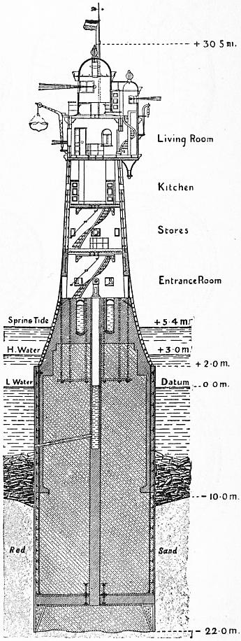 |
| Fig. 21.—Rothersand Lighthouse. |
The object of these several forms of optical apparatus is not only to produce characteristics or distinctions in lights to enable them to be readily recognized by mariners, but to utilize the light rays in directions above and below the horizontal plane, and also, in the case of revolving or flashing lights, in azimuths not requiring to be illuminated for strengthening the beam in the direction of the mariner. It will be seen that the effective condensation in flashing lights is very much greater than in fixed belts, thus enabling higher intensities to be obtained by the use of flashing lights than with fixed apparatus.
The purpose of these various types of optical devices is not only to create features or differences in lights that help mariners easily identify them, but also to make use of the light rays in angles above and below the horizontal plane. Additionally, for revolving or flashing lights, they aim to illuminate azimuths that don't need to be lit, which helps strengthen the beam in the direction of the mariner. You'll notice that the effective concentration in flashing lights is much greater than in fixed lights, allowing for higher intensities to be achieved with flashing lights compared to fixed devices.
Catoptric System.—Parabolic reflectors, consisting of small facets of silvered glass set in plaster of Paris, were first used about the year 1763 in some of the Mersey lights by Mr Hutchinson, then dock master at Liverpool (fig. 29). Spherical metallic reflectors were introduced in France in 1781, followed by parabolic reflectors on silvered copper in 1790 in England and France, and in Scotland in 1803. The earlier lights were of fixed type, a number of reflectors being arranged on a frame or stand in such a manner that the pencils of emergent rays overlapped and thus illuminated the whole horizon continuously. In 1783 the first revolving light was erected at Marstrand in Sweden. Similar apparatus were installed at Cordouan (1790), Flamborough Head (1806) and at the Bell Rock (1811). To produce a revolving or flashing light the reflectors were fixed on a revolving carriage having several faces. Three or more reflectors in a face were set with their axes parallel.
Catoptric System.—Parabolic reflectors, made of small facets of silvered glass embedded in plaster of Paris, were first utilized around 1763 in some of the Mersey lights by Mr. Hutchinson, who was then the dock master in Liverpool (fig. 29). Spherical metallic reflectors were introduced in France in 1781, which was followed by parabolic reflectors made of silvered copper in England and France in 1790, and in Scotland in 1803. The earlier lights were of a fixed type, with multiple reflectors organized on a frame or stand in such a way that the beams of emerging rays overlapped, continuously lighting up the entire horizon. In 1783, the first revolving light was established at Marstrand in Sweden. Similar equipment was installed at Cordouan (1790), Flamborough Head (1806), and at the Bell Rock (1811). To create a revolving or flashing light, the reflectors were mounted on a rotating carriage with several faces. Three or more reflectors on a face were aligned with their axes parallel.
A type of parabolic reflector now in use is shown in fig. 30. The sizes in general use vary from 21 in. to 24 in. diameter. These instruments are still largely used for light-vessel illumination, and a few important land lights are at the present time of catoptric type, including those at St Agnes (Scilly Islands), Cromer and St Anthony (Falmouth).
A type of parabolic reflector currently in use is shown in fig. 30. The sizes commonly used range from 21 inches to 24 inches in diameter. These devices are still widely used for illuminating light vessels, and a few significant land lights today are of the catoptric type, including those at St. Agnes (Scilly Islands), Cromer, and St. Anthony (Falmouth).
 |
| Fig. 22.—Courses of various Lighthouse Towers. |
 |
 |
| Fig. 23.—Perspective drawing of Dovetailed Stone (Wolf Rock). |
Fig. 24.—Section of Dovetail. |
Dioptric System.—The first adaptation of dioptric lenses to lighthouses is probably due to T. Rogers, who used lenses at one of the Portland lighthouses between 1786 and 1790. Subsequently lenses by the same maker were used at Howth, Waterford and the North Foreland. Count Buffon had in 1748 proposed to grind out of a solid piece of glass a lens in steps or concentric zones in order to reduce the thickness to a minimum (fig. 31). Condorcet in 1773 and Sir D. Brewster in 1811 designed built-up lenses consisting of stepped annular rings. Neither of these proposals, however, was intended to apply to lighthouse purposes. In 1822 Augustin Fresnel constructed a built-up annular lens in which the centres of curvature of the different rings receded from the axis according to their distances from the centre, so as practically to eliminate spherical aberration; the only spherical surface being the small central part or “bull’s eye” (fig. 32). These lenses were intended for revolving lights only. Fresnel next produced his cylindric refractor or lens belt, consisting 634 of a zone of glass generated by the revolution round a vertical axis of a medial section of the annular lens (fig. 33). The lens belt condensed and parallelized the light rays in the vertical plane only, while the annular lens does so in every plane. The first revolving light constructed from Fresnel’s designs was erected at the Cordouan lighthouse in 1823. It consisted of 8 panels of annular lenses placed round the lamp at a focal distance of 920 mm. To utilize the light, which would otherwise escape above the lenses, Fresnel introduced a series of 8 plain silvered mirrors, on which the light was thrown by a system of lenses. At a subsequent period mirrors were also placed in the lower part of the optic. The apparatus was revolved by clockwork. This optic embodied the first combination of dioptric and catoptric elements in one design (fig. 34). In the following year Fresnel designed a dioptric lens with catoptric mirrors for fixed light, which was the first of its kind installed in a lighthouse. It was erected at the Chassiron lighthouse in 1827 (fig. 35). This combination is geometrically perfect, but not so practically on account of the great loss of light entailed by metallic reflection which is at least 25% greater than the system described under. Before his death in 1827 Fresnel devised his totally reflecting or catadioptric prisms to take the place of the silvered reflectors previously used above and below the lens elements (fig. 28). The ray Fi falling on the prismoidal ring ABC is refracted in the direction i r and meeting the face AB at an angle of incidence greater than the critical, is totally reflected in the direction r e emerging after second refraction in a horizontal direction. Fresnel devised these prisms for use in fixed light apparatus, but the principle was, at a later date, also applied to flashing lights, in the first instance by T. Stevenson. Both the dioptric lens and catadioptric prism invented by Fresnel are still in general use, the mathematical calculations of the great French designer still forming the basis upon which lighthouse opticians work.
Dioptric System.—The first use of dioptric lenses in lighthouses was likely by T. Rogers, who implemented lenses at one of the Portland lighthouses between 1786 and 1790. Later, lenses from the same manufacturer were utilized at Howth, Waterford, and the North Foreland. Count Buffon suggested in 1748 that lenses could be crafted from a solid piece of glass in steps or concentric zones to minimize thickness (fig. 31). Condorcet in 1773 and Sir D. Brewster in 1811 designed stacked lenses composed of stepped annular rings, but neither of these concepts was aimed at lighthouse applications. In 1822, Augustin Fresnel created a built-up annular lens where the centers of curvature of the various rings receded from the axis based on their distance from the center, effectively eliminating spherical aberration; the only spherical surface being the small central part or “bull’s eye” (fig. 32). These lenses were meant for revolving lights only. Fresnel then developed his cylindrical refractor or lens belt, made of a glass zone produced by revolving a medial section of the annular lens around a vertical axis (fig. 33). The lens belt concentrated and aligned the light rays only in the vertical plane, while the annular lens did so in every plane. The first revolving light made from Fresnel’s designs was installed at the Cordouan lighthouse in 1823. It included 8 panels of annular lenses arranged around the lamp at a focal distance of 920 mm. To capture light that would otherwise escape above the lenses, Fresnel added a series of 8 plain silvered mirrors, which redirected the light using a lens system. Later, mirrors were also positioned in the lower part of the optic. The system was rotated by clockwork. This optic represented the first integration of dioptric and catoptric elements in one design (fig. 34). The following year, Fresnel designed a dioptric lens incorporating catoptric mirrors for fixed light, which was the first of its kind installed in a lighthouse at Chassiron in 1827 (fig. 35). While this combination is geometrically flawless, it is less practical due to significant light loss from metallic reflection, which is at least 25% more than the previous system. Before his death in 1827, Fresnel invented his totally reflecting or catadioptric prisms to replace the silvered reflectors used above and below the lens elements (fig. 28). The ray Fi striking the prismoidal ring ABC is refracted in the direction i r and, meeting face AB at an angle of incidence exceeding the critical angle, is totally reflected in the direction r e, emerging after a second refraction horizontally. Fresnel designed these prisms for fixed light systems, but the principle was later applied to flashing lights, initially by T. Stevenson. Both the dioptric lens and catadioptric prism created by Fresnel are still widely used, with the mathematical calculations of the great French designer continuing to inform the work of lighthouse opticians.
 |
 |
| Fig. 25.—Dassen Island Lighthouse (cast iron). |
Fig. 26.—Cape San Thomé Lighthouse. |
 |
 |
| Fig. 27.—Dioptric Prism. | Fig. 28.—Catadioptric or Reflecting Prism. |
Fresnel also designed a form of fixed and flashing light in which the distinction of a fixed light, varied by flashes, was produced by placing panels of straight refracting prisms in a vertical position on a revolving carriage outside the fixed light apparatus. The revolution of the upright prisms periodically increased the power of the beam, by condensation of the rays emergent from the fixed apparatus, in the horizontal plane.
Fresnel also created a type of fixed and flashing light where the fixed light was varied by flashes by placing vertical panels of straight refracting prisms on a rotating carriage outside the fixed light setup. The rotation of the upright prisms periodically boosted the intensity of the beam by concentrating the rays coming from the fixed apparatus in the horizontal plane.
The lens segments in Fresnel’s early apparatus were of polygonal form instead of cylindrical, but subsequently manufacturers succeeded in grinding glass in cylindrical rings of the form now used. The first apparatus of this description was made by Messrs Cookson of Newcastle in 1836 at the suggestion of Alan Stevenson and erected at Inchkeith.
The lens segments in Fresnel’s early device were shaped like polygons instead of being cylindrical, but later on, manufacturers managed to grind glass into cylindrical rings like the ones we use today. The first device of this kind was created by Cookson & Co. of Newcastle in 1836 at the suggestion of Alan Stevenson and set up at Inchkeith.
In 1825 the French Commission des Phares decided upon the exclusive use of lenticular apparatus in its service. The Scottish Lighthouse Board followed with the Inchkeith revolving apparatus in 1835 and the Isle of May fixed optic in 1836. In the latter instrument Alan Stevenson introduced helical frames for holding the glass prisms in place, thus avoiding complete obstruction of the light rays in any azimuth. The first dioptric light erected by the Trinity House was that formerly at Start Point in Devonshire, constructed in 1836. Catadioptric or reflecting prisms for revolving lights were not used until 1850, when Alan Stevenson designed them for the North Ronaldshay lighthouse.
In 1825, the French Commission des Phares decided to exclusively use lenticular apparatus in its operations. The Scottish Lighthouse Board followed suit with the Inchkeith revolving apparatus in 1835 and the Isle of May fixed optic in 1836. In the latter instrument, Alan Stevenson introduced helical frames to hold the glass prisms in place, preventing the complete obstruction of light rays in any direction. The first dioptric light built by the Trinity House was the one that was previously at Start Point in Devonshire, constructed in 1836. Catadioptric or reflecting prisms for revolving lights weren't used until 1850, when Alan Stevenson designed them for the North Ronaldshay lighthouse.
Dioptric Mirror.—The next important improvement in lighthouse optical work was the invention of the dioptric spherical mirror by Mr (afterwards Sir) J. T. Chance in 1862. The zones or prisms are generated round a vertical axis and divided into segments. This form of mirror is still in general use (figs. 36 and 37).
Dioptric Mirror.—The next significant advancement in lighthouse optics was the creation of the dioptric spherical mirror by Mr. (later Sir) J. T. Chance in 1862. The zones or prisms are shaped around a vertical axis and divided into segments. This type of mirror is still commonly used (figs. 36 and 37).
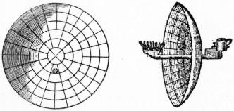 |
 |
| Fig. 29.—Early Reflector and Lamp (1763). | Fig. 30.—Modern Parabolic Reflector. |
Azimuthal Condensing Prisms.—Previous to 1850 all apparatus were designed to emit light of equal power in every azimuth either constantly or periodically. The only exception was where a light was situated on a stretch of coast where a mirror could be placed behind the flame to utilize the rays, which would otherwise pass landward, and reflect them back, passing through the flame and lens in a seaward direction. In order to increase the intensity of lights in certain azimuths T. Stevenson devised his azimuthal condensing prisms which, in various forms and methods of application, have been largely used for the purpose of strengthening the light rays in required directions as, for instance, where coloured sectors are provided. Applications of this system will be referred to subsequently.
Azimuthal Condensing Prisms.—Before 1850, all devices were made to emit light with equal strength in every direction, whether constantly or at intervals. The only exception was in locations along the coast where a mirror could be positioned behind the flame to capture rays that would otherwise head towards land, reflecting them back through the flame and lens out to sea. To boost the intensity of lights in specific directions, T. Stevenson developed his azimuthal condensing prisms, which have been extensively used in various forms and methods to enhance light rays in desired directions, particularly in cases where colored sectors are included. Further applications of this system will be discussed later.
Optical Glass for Lighthouses.—In the early days of lens lights the only glass used for the prisms was made in France at the St Gobain and Premontré works, which have long been celebrated for the high quality of optical glass produced. The early dioptric lights erected in the United Kingdom, some 13 in all, were made by Messrs Cookson of South Shields, who were instructed by Léonor Fresnel, the brother of Augustin. At first they tried to mould the lens and then to grind it out of one thick sheet of glass. The successors of the Cookson firm abandoned the manufacture of lenses in 1845, and the firm of Letourneau & Lepaute of Paris again became the monopolists. In 1850 Messrs Chance Bros. & Co. of Birmingham began the manufacture of optical glass, assisted by M. Tabouret, a French expert who had been a colleague of Augustin Fresnel himself. The first light made by the firm was shown at the Great Exhibition of 1851, since when numerous dioptric apparatus have been constructed by Messrs Chance, who are, at this time, the only manufacturers of lighthouse glass in the United Kingdom. Most of the glass used for apparatus constructed in France is manufactured at St Gobain. Some of the glass used by German constructors is made at Rathenow in Prussia and Goslar in the Harz.
Optical Glass for Lighthouses.—In the early days of lens lights, the only glass used for the prisms was made in France at the St Gobain and Premontré factories, which have long been known for the high quality of optical glass they produced. The early dioptric lights set up in the United Kingdom, about 13 in total, were made by Messrs Cookson from South Shields, who were guided by Léonor Fresnel, the brother of Augustin. Initially, they attempted to mold the lens and then to grind it from one thick sheet of glass. The successors of the Cookson firm stopped making lenses in 1845, and the firm of Letourneau & Lepaute from Paris once again became the sole manufacturers. In 1850, Messrs Chance Bros. & Co. from Birmingham started producing optical glass, with the help of M. Tabouret, a French expert who had worked alongside Augustin Fresnel himself. The first light produced by the firm was displayed at the Great Exhibition of 1851, and since then, many dioptric devices have been created by Messrs Chance, who are currently the only manufacturers of lighthouse glass in the United Kingdom. Most of the glass used for devices made in France is produced at St Gobain. Some of the glass used by German manufacturers is sourced from Rathenow in Prussia and Goslar in the Harz.
The glass generally employed for lighthouse optics has for its refractive index a mean value of µ = 1.51, the corresponding critical angle being 41° 30′. Messrs Chance have used dense flint glass for the upper and lower refracting rings of high angle lenses and for dioptric mirrors in certain cases. This glass has a value of µ = l.62 with critical angle 38° 5′.
The glass commonly used for lighthouse optics has an average refractive index of µ = 1.51, with a corresponding critical angle of 41° 30'. Chance & Co. have utilized dense flint glass for the upper and lower refracting rings of high angle lenses and for dioptric mirrors in specific instances. This type of glass has a refractive index of µ = 1.62 and a critical angle of 38° 5'.
 |
 |
 |
| Fig. 31. Buffon’s Lens. |
Fig. 32. Fresnel’s Annular Lens. |
Fig. 33. Fresnel’s Lens Belt. |
 |
| Fig. 34.—Fresnel’s Revolving Apparatus at Cordouan Lighthouse. |
Occulting Lights.—During the last 25 years of the 19th century the disadvantages of fixed lights became more and more apparent. At the present day the practice of installing such, except occasionally in the case of the smaller and less important of harbour or river lights, has practically ceased. The necessity for providing a distinctive characteristic for every light when possible has led to the conversion of many of the fixed-light apparatus of earlier years into occulting lights, and often to their supersession by more modern and powerful flashing apparatus. An occulting apparatus in general use consists of a cylindrical screen, fitting over the burner, rapidly lowered and raised by means of a cam-wheel at stated intervals. The cam-wheel is actuated by means of a weight or spring clock. Varying characteristics may be procured by means of such a contrivance—single, double, triple or other systems of occultation. The eclipses or periods of darkness bear much the same relation to the times of illumination as do the flashes to the eclipses in a revolving or flashing light. In the case of a first-order fixed light the cost of conversion to an occulting characteristic does not exceed £250 to £300. With apparatus illuminated by gas the occultations may be produced by successively raising and lowering the gas at stated intervals. Another form of occulting mechanism employed consists of a series of vertical screens mounted on a carriage and revolving round the burner. The carriage is rotated on rollers or ball bearings or carried upon a small mercury float. The usual driving mechanism employed is a spring clock. “Otter” screens are used in cases when it is desired to produce different periods of occultations in two or more positions in azimuth in order to differentiate sectors marking shoals, &c. The screens are of sheet metal blacked and arranged vertically, some what in the manner of the laths of a venetian blind, and operated by mechanical means.
Occulting Lights.—During the last 25 years of the 19th century, the downsides of fixed lights became increasingly clear. Nowadays, the practice of installing such lights has almost completely stopped, except occasionally for smaller and less significant harbor or river lights. The need to provide a unique characteristic for every light whenever possible has resulted in converting many of the fixed-light devices from earlier years into occulting lights, and they are often replaced by more modern and powerful flashing systems. An occulting apparatus commonly used consists of a cylindrical screen that fits over the burner, which is quickly raised and lowered by a cam-wheel at set intervals. The cam-wheel is powered by a weight or a spring clock. Different characteristics can be achieved with such a setup—single, double, triple, or other systems of occultation. The periods of darkness relate to the times of illumination much like flashes relate to the eclipses in a revolving or flashing light. For a first-order fixed light, the cost to convert it to an occulting characteristic is usually between £250 to £300. For gas-lit apparatus, occultations can be created by raising and lowering the gas at set intervals. Another type of occulting mechanism used consists of a series of vertical screens mounted on a carriage that revolves around the burner. The carriage is rotated on rollers or ball bearings or is placed on a small mercury float. The standard driving mechanism used is a spring clock. “Otter” screens are employed when it is necessary to create different periods of occultation in two or more positions in azimuth to distinguish sectors marking shoals, etc. These screens are made of blackened sheet metal, arranged vertically, somewhat like the slats of a Venetian blind, and operated by mechanical means.
Leading Lights.—In the case of lights designed to act as a lead through a narrow channel or as direction lights, it is undesirable to employ a flashing apparatus. Fixed-light optics are employed to meet such cases, and are generally fitted with occulting mechanism. A typical apparatus of this description is that at Gage Roads, Fremantle, West Australia (fig. 38). The occulting bright light covers the fairway, and is flanked by sectors of occulting red and green light marking dangers and intensified by vertical condensing prisms. A good example of a holophotal direction light was exhibited at the 1900 Paris Exhibition, and afterwards erected at Suzac lighthouse (France). The light consists of an annular lens 500 mm. focal distance, of 180° horizontal angle and 157° vertical, with a mirror of 180° at the back. The lens throws a red beam of about 4½° amplitude in azimuth, and 50,000 candle-power over a narrow channel. The illuminant is an incandescent petroleum vapour burner. Holophotal direction lenses of this type can only be applied where the sector to be marked is of comparatively small angle. Silvered metallic mirrors of parabolic form are also used for the purpose. The use of single direction lights frequently renders the construction of separate towers for leading lights unnecessary.
Leading Lights.—For lights designed to guide through a narrow channel or serve as directional lights, using a flashing mechanism is not ideal. Fixed-light optics are used in these situations and usually come with an occulting mechanism. A typical example of this is at Gage Roads, Fremantle, West Australia (fig. 38). The occulting bright light covers the navigable area and is flanked by sectors of occulting red and green light that highlight hazards, enhanced by vertical condensing prisms. A good example of a holophotal direction light was presented at the 1900 Paris Exhibition and later installed at the Suzac lighthouse in France. The light features an annular lens with a 500 mm focal distance, a 180° horizontal angle, and a 157° vertical angle, with a mirror at the back covering 180°. The lens emits a red beam with about a 4½° spread in azimuth and 50,000 candle-power over a narrow channel. The light source is an incandescent petroleum vapor burner. Holophotal direction lenses of this kind can only be used where the area to be marked is relatively small in angle. Parabolic silvered metallic mirrors are also employed for this purpose. The use of individual direction lights often eliminates the need for separate towers for leading lights.
If two distinct lights are employed to indicate the line of navigation through a channel or between dangers they must be sufficiently far apart to afford a good lead, the front or seaward light being situated at a lower elevation than the rear or landward one.
If two different lights are used to show the navigation line through a channel or between hazards, they need to be far enough apart to provide clear guidance, with the front or seaward light positioned at a lower height than the rear or landward light.
Coloured Lights.—Colour is used as seldom as possible as a distinction, entailing as it does a considerable reduction in the power of the light. It is necessary in some instances for differentiating sectors over dangers and for harbour lighting purposes. The use of coloured lights as alternating flashes for lighthouse lights is not to be commended, on account of the unequal absorption of the coloured 636 and bright rays by the atmosphere. When such distinction has been employed, as in the Wolf Rock apparatus, the red and white beams can be approximately equalized in initial intensity by constructing the lens and prism panels for the red light of larger angle than those for the white beams. Owing to the absorption by the red colouring, the power of a red beam is only 40% of the intensity of the corresponding white light. The corresponding intensity of green light is 25%. When red or green sectors are employed they should invariably be reinforced by mirrors, azimuthal condensing prisms, or other means to raise the coloured beam to approximately the same intensity as the white light. With the introduction of group-flashing characteristics the necessity for using colour as a means of distinction disappeared.
Colored Lights.—Color is used as sparingly as possible because it significantly reduces the light's power. It's necessary in certain cases to differentiate areas over hazards and for harbor lighting. Using colored lights as alternating flashes for lighthouse signals is not recommended due to the uneven absorption of colored and bright rays by the atmosphere. In cases where such differentiation has been used, like the Wolf Rock system, the red and white beams can be made roughly equal in initial intensity by designing the lens and prism panels for the red light with a larger angle than those for the white beams. Due to the absorption from the red color, the intensity of a red beam is only 40% of the corresponding white light. The intensity of green light is 25%. When red or green sectors are used, they should always be strengthened with mirrors, azimuthal condensing prisms, or other methods to boost the colored beam to approximately the same intensity as the white light. With the introduction of group-flashing characteristics, the need for using color as a way to distinguish signals has disappeared.
 |
| Fig. 35.—Fixed Apparatus at Chassiron Lighthouse (1827). |
 |
| Fig. 36.—Vertical Section. Prism of Dioptric Spherical Mirror. |
High-Angle Vertical Lenses.—Messrs Chance of Birmingham have manufactured lenses having 97° of vertical amplitude, but this result was only attained by using dense flint glass of high refractive index for the upper and lower elements. It is doubtful, however, whether the use of refracting elements for a greater angle than 80° vertically is attended by any material corresponding advantage.
High-Angle Vertical Lenses.—Chance of Birmingham has produced lenses with a vertical range of 97°, but this was only achieved by using dense flint glass with a high refractive index for the top and bottom elements. However, it's uncertain whether incorporating refracting elements for a vertical angle greater than 80° offers any significant benefits.
 |
| Fig. 37.—Chance’s Dioptric Spherical Mirror. |
Group Flashing Lights.—One of the most useful distinctions consists in the grouping of two or more flashes separated by short intervals of darkness, the group being succeeded by a longer eclipse. Thus two, three or more flashes of, say, half second duration or less follow each other at intervals of about 2 seconds and are succeeded by an eclipse of, say, 10 seconds, the sequence being completed in a period of, say, 15 seconds. In 1874 Dr John Hopkinson introduced the very valuable improvement of dividing the lenses of a dioptric revolving light with the panels of reflecting prisms above and below them, setting them at an angle to produce the group-flashing characteristic. The first apparatus of this type constructed were those now in use at Tampico, Mexico and the Little Basses lighthouse, Ceylon (double flashing). The Casquets apparatus (triple flashing) was installed in 1877. A group-flashing catoptric light had, however, been exhibited from the “Royal Sovereign” light-vessel in 1875. A sectional plan of the quadruple-flashing first order apparatus at Pendeen in Cornwall is shown in fig. 39; and fig. 55 (Plate 1.) illustrates a double flashing first order light at Pachena Point in British Columbia. Hopkinson’s system has been very extensively used, most of the group-flashing lights shown in the accompanying tables, being designed upon the general lines he introduced. A modification of the system consists in grouping two or more lenses together separated by equal angles, and filling the remaining angle in azimuth by a reinforcing mirror or screen. A group-flashing distinction was proposed for gas lights by J. R. Wigham of Dublin, who obtained it in the case of a revolving apparatus by alternately raising and lowering the flame. The first apparatus in which this method was employed was erected at Galley Head, Co. Cork (1878). At this lighthouse 4 of Wigham’s large gas burners with four tiers of first-order revolving lenses, eight in each tier, were adopted. By successive lowering and raising of the gas flame at the focus of each tier of lenses he produced the group-flashing distinction. The light showed, instead of one prolonged flash at intervals of one minute, as would be produced by the apparatus in the absence of a gas occulter, a group of short flashes varying in number between six and seven. The uncertainty, however, in the number of flashes contained in each group is found to be an objection to the arrangement. This device was adopted at other gas-illuminated stations in Ireland at subsequent dates. The quadriform apparatus and gas installation at Galley Head were superseded in 1907 by a first order bi-form apparatus with incandescent oil vapour burner showing five flashes every 20 seconds.
Group Flashing Lights.—One of the most helpful distinctions is the grouping of two or more flashes spaced by brief periods of darkness, followed by a longer blackout. For instance, two, three, or more flashes lasting about half a second or less occur at intervals of roughly two seconds, followed by an eclipse lasting about ten seconds, completing the sequence in around fifteen seconds. In 1874, Dr. John Hopkinson introduced a valuable improvement by dividing the lenses of a dioptric revolving light with panels of reflecting prisms positioned above and below, angled to create the group-flashing effect. The first devices of this kind were those currently in use at Tampico, Mexico, and the Little Basses lighthouse in Ceylon (double flashing). The Casquets apparatus (triple flashing) was set up in 1877. However, a group-flashing catoptric light had already been demonstrated from the “Royal Sovereign” light-vessel in 1875. A sectional plan of the quadruple-flashing first order apparatus at Pendeen in Cornwall is shown in fig. 39; and fig. 55 (Plate 1) illustrates a double flashing first order light at Pachena Point in British Columbia. Hopkinson’s system has been widely implemented, with most of the group-flashing lights listed in the accompanying tables designed based on the general principles he introduced. A variation of the system involves grouping two or more lenses together at equal angles and filling the remaining azimuth angle with a reinforcing mirror or screen. J. R. Wigham of Dublin proposed a group-flashing distinction for gas lights, achieving it with a revolving device by alternately raising and lowering the flame. The first setup using this method was installed at Galley Head, Co. Cork (1878). At this lighthouse, four of Wigham’s large gas burners with four tiers of first-order revolving lenses, eight lenses per tier, were adopted. By successively lowering and raising the gas flame at the focus of each tier, he produced the group-flashing effect. Instead of one long flash every minute—which would occur without a gas occluder—the light displayed a group of short flashes varying between six and seven. However, the inconsistency in the number of flashes per group has been noted as a drawback to this setup. This method was later adopted at other gas-lit stations in Ireland. The quadriform apparatus and gas installation at Galley Head were replaced in 1907 by a first order bi-form apparatus with an incandescent oil vapor burner, showing five flashes every 20 seconds.
 |
| Fig. 38.—Gage Roads Direction Light. |
 |
| Fig. 39.—Pendeen Apparatus. Plan at Focal Plane. |
Flashing Lights indicating Numbers.—Captain F. A. Mahan, late engineer secretary to the United States Lighthouse Board, devised for that service a system of flashing lights to indicate certain numbers. The apparatus installed at Minot’s Ledge lighthouse near Boston Harbour, Massachusetts, has a flash indicating the number 143, thus: - ---- ---, the dashes indicating short flashes. Each group is separated by a longer period of darkness than that between successive members of a group. The flashes in a group indicating a figure are about 1½ seconds apart, the groups being 3 seconds apart, an interval of 16 seconds’ darkness occurring between each repetition. Thus the number is repeated every half minute. Two examples of this system were exhibited by the United States Lighthouse Board at the Chicago Exhibition in 1893, viz. the second-order apparatus just mentioned and a similar light of the first order for Cape Charles on the Virginian coast. The lenses are arranged in a somewhat 637 similar manner to an ordinary group-flashing light, the groups of lenses being placed on one side of the optic, while the other is provided with a catadioptric mirror. This system of numerical flashing for lighthouses has been frequently proposed in various forms, notably by Lord Kelvin. The installation of the lights described is, however, the first practical application of the system to large and important coast lights. The great cost involved in the alteration of the lights of any country to comply with the requirements of a numerical system is one of the objections to its general adoption.
Flashing Lights Indicating Numbers.—Captain F. A. Mahan, who was the engineer secretary for the United States Lighthouse Board, created a system of flashing lights to represent specific numbers. The setup installed at Minot’s Ledge lighthouse near Boston Harbor, Massachusetts, has a flash that indicates the number 143, formatted as: - ---- ---, with the dashes representing short flashes. Each group is separated by a longer period of darkness compared to the intervals between the flashes in a group. The flashes within a group that indicate a number are about 1½ seconds apart, and the groups are separated by 3 seconds, with a total of 16 seconds of darkness occurring between each repetition. This means the number repeats every half minute. Two examples of this system were displayed by the United States Lighthouse Board at the Chicago Exhibition in 1893: the previously mentioned second-order apparatus and a similar first-order light for Cape Charles on the Virginia coast. The lenses are arranged somewhat like an ordinary group-flashing light, with the lens groups positioned on one side of the optic, while the other side has a catadioptric mirror. This system of numerical flashing for lighthouses has been proposed multiple times in different forms, especially by Lord Kelvin. Nonetheless, the lights described represent the first practical use of the system for large and significant coastal lights. The high cost associated with modifying the lights of any country to meet the needs of a numerical system is one of the main drawbacks to its widespread implementation.
Plate I.
Plate 1.
 |
 |
| Fig. 54.—FASTNET LIGHTHOUSE—FIRST ORDER SINGLE-FLASHING BIFORM APPARATUS. | Fig. 55.—PACHENA POINT LIGHTHOUSE, BCE—FIRST ORDER DOUBLE-FLASHING APPARATUS. |
Plate II.
Plate 2.
 |
 |
| Fig. 56.—OLD EDDYSTONE LIGHTHOUSE. | Fig. 57.—EDDYSTONE LIGHTHOUSE. |
 |
 |
| Fig. 58.—ILE VIERGE LIGHTHOUSE. | Fig. 59.—MINOT’S LEDGE LIGHTHOUSE. |
 |
| Fig. 40.—Sule Skerry Apparatus. |
Hyper-radial Apparatus.—In 1885 Messrs Barbier of Paris constructed the first hyper-radial apparatus (1330 mm. focal distance) to the design of Messrs D. and C. Stevenson. This had a height of 1812 mm. It was tested during the South Foreland experiments in comparison with other lenses, and found to give excellent results with burners of large focal diameter. Apparatus of similar focal distance (1330 mm.) were subsequently established at Round Island, Bishop Rock, and Spurn Point in England, Fair Isle and Sule Skerry (fig. 40) in Scotland, Bull Rock and Tory Island in Ireland, Cape d’Antifer in France, Pei Yu-shan in China and a lighthouse in Brazil.
Hyper-radial Apparatus.—In 1885, Messrs Barbier of Paris built the first hyper-radial apparatus (1330 mm focal distance) based on the design by Messrs D. and C. Stevenson. It stood 1812 mm tall. It was tested during the South Foreland experiments alongside other lenses and was found to produce excellent results with burners that had a large focal diameter. Similar apparatuses with a 1330 mm focal distance were later set up at Round Island, Bishop Rock, and Spurn Point in England, Fair Isle and Sule Skerry (fig. 40) in Scotland, Bull Rock and Tory Island in Ireland, Cape d’Antifer in France, Pei Yu-shan in China, and a lighthouse in Brazil.
The light erected in 1907 at Cape Race, Newfoundland, is a fine example of a four-sided hyper-radial apparatus mounted on a mercury float. The total weight of the revolving part of the light amounts to 7 tons, while the motive clock weight required to rotate this large mass at a speed of two complete revolutions a minute is only 8 cwt. and the weight of mercury required for flotation 950 ℔. A similar apparatus was placed at Manora Point, Karachi, India, in 1908 (fig. 41).
The lighthouse built in 1907 at Cape Race, Newfoundland, is a great example of a four-sided hyper-radial system mounted on a mercury float. The total weight of the rotating part of the light is 7 tons, while the clock weight needed to turn this heavy mass at a speed of two full revolutions per minute is just 8 cwt. The weight of mercury needed for flotation is 950 lbs. A similar system was installed at Manora Point, Karachi, India, in 1908 (fig. 41).
The introduction of incandescent and other burners of focal compactness and high intensity has rendered the use of optics of such large dimensions as the above, intended for burners of great focal diameter, unnecessary. It is now possible to obtain with a second-order optic (or one of 700 mm. focal distance), having a powerful incandescent petroleum burner in focus, a beam of equal intensity to that which would be obtained from the apparatus having a 10-wick oil burner or 108-jet gas burner at its focus.
The introduction of incandescent lights and other compact, high-intensity burners has made the use of large optics like the ones mentioned above, designed for burners with a wide focal diameter, unnecessary. Now, it's possible to achieve a beam of equal intensity using a second-order optic (or one with a 700 mm focal distance) focused on a powerful incandescent petroleum burner, similar to what would be produced by a setup with a 10-wick oil burner or a 108-jet gas burner.
Stephenson’s Spherical Lenses and Equiangular Prisms.—Mr C. A. Stephenson in 1888 designed a form of lens spherical in the horizontal and vertical sections. This admitted of the construction of lenses of long focal distance without the otherwise corresponding necessity of increased diameter of lantern. A lens of this type and of 1330 mm. focal distance was constructed in 1890 for Fair Isle lighthouse. The spherical form loses in efficiency if carried beyond an angle subtending 20° at the focus, and to obviate this loss Mr Stephenson designed his equiangular prisms, which have an inclination outwards. It is claimed by the designer that the use of equiangular prisms results in less loss of light and less divergence than is the case when either the spherical or Fresnel form is adopted. An example of this design is seen (fig. 40) in the Sule Skerry apparatus (1895).
Stephenson’s Spherical Lenses and Equiangular Prisms.—In 1888, Mr. C. A. Stephenson created a type of lens that is spherical in both the horizontal and vertical sections. This design allowed for the construction of lenses with a long focal distance without needing to increase the diameter of the lantern. A lens of this type, with a focal distance of 1330 mm, was made in 1890 for the Fair Isle lighthouse. However, the spherical shape loses efficiency when the angle at the focus exceeds 20°. To address this issue, Mr. Stephenson developed his equiangular prisms, which are angled outward. The designer claims that using equiangular prisms results in less light loss and less divergence compared to either spherical or Fresnel lenses. An example of this design can be seen (fig. 40) in the Sule Skerry apparatus (1895).
Fixed and Flashing Lights.—The use of these lights, which show a fixed beam varied at intervals by more powerful flashes, is not to be recommended, though a large number were constructed in the earlier years of dioptric illumination and many are still in existence. The distinction can be produced in one or other of three ways: (a) by the revolution of detached panels of straight condensing lens prisms placed vertically around a fixed light optic, (b) by utilizing revolving lens panels in the middle portion of the optic to produce the flashing light, the upper and lower sections of the apparatus being fixed zones of catadioptric or reflecting elements emitting a fixed belt of light, and (c) by interposing panels of fixed light section between the flashing light panels of a revolving apparatus. In certain conditions of the atmosphere it is possible for the fixed light of low power to be entirely obscured while the flashes are visible, thus vitiating the true characteristic of the light. Cases have frequently occurred of such lights being mistaken for, and even described in lists of light as, revolving or flashing lights.
Fixed and Flashing Lights.—Using these lights, which have a steady beam with intermittent stronger flashes, is not recommended, even though many were made in the early days of dioptric lighting and many still exist today. The distinction can be achieved in one of three ways: (a) by rotating separate panels of straight condensing lens prisms arranged vertically around a stationary light, (b) by using revolving lens panels in the middle of the light to create the flashing effect, while the upper and lower parts have fixed zones of catadioptric or reflecting elements that emit a steady band of light, and (c) by placing panels of fixed light sections between the flashing panels of a rotating setup. In certain weather conditions, the low-power fixed light can become completely obscured while the flashes remain visible, which can distort the true characteristic of the light. There have been many instances where these lights have been mistaken for, and even listed as, revolving or flashing lights.
”Cute” and Screens.—Screens of coloured glass, intended to distinguish the light in particular azimuths, and of sheet iron, when it is desired to “cut off” the light sharply on any angle, should be fixed as far from the centre of the light as possible in order to reduce the escape of light rays due to divergence. These screens are usually attached to the lantern framing.
”Cute” and Screens.—Screens made of colored glass, meant to define the light in specific directions, and those made from sheet metal, when the goal is to sharply limit the light at any angle, should be installed as far from the center of the light as possible to minimize the loss of light rays due to divergence. These screens are typically mounted on the lantern frame.
Divergence.—A dioptric apparatus designed to bend all incident rays of light from the light source in a horizontal direction would, if the flame could be a point, have the effect of projecting a horizontal band or zone of light, in the case of a fixed apparatus, and a cylinder of light rays, in the case of a flashing light, towards the horizon. Thus the mariner in the near distance would receive no light, the rays, visible only at or near the horizon, passing above the level of his eye. In practice this does not occur, sufficient natural divergence being produced ordinarily owing to the magnitude of the flame. Where the electric arc is employed it is often necessary to design the prisms so as to produce artificial divergence. The measure of the natural divergence for any point of the lens is the angle whose sine is the ratio of the diameter of the flame to the distance of the point from centre of flame.
Divergence.—A light system designed to direct all incoming rays from the light source horizontally would, if the flame were a point, create a horizontal band or zone of light with a fixed setup and a cylinder of light rays with a flashing light aimed at the horizon. This means that a sailor nearby wouldn't perceive any light, as the rays would only be visible near the horizon, passing above their eye level. However, in reality, this doesn’t happen because the size of the flame usually creates enough natural divergence. When using an electric arc, it's often necessary to design the prisms to create artificial divergence. The natural divergence for any point on the lens is measured by the angle whose sine is the ratio of the flame's diameter to the distance from that point to the center of the flame.
In the case of vertical divergence the mean height of the flame must be substituted for the diameter. The angle thus obtained is the total divergence, that is, the sum of the angles above and below the horizontal plane or to right and left of the medial section. In fixed dioptric lights there is, of course, no divergence in the horizontal plane. In flashing lights the horizontal divergence is a matter of considerable importance, determining as it does the duration or length of time the flash is visible to the mariner.
In the case of vertical divergence, the average height of the flame needs to replace the diameter. The angle obtained this way is the total divergence, which is the sum of the angles above and below the horizontal plane or to the right and left of the middle section. In fixed dioptric lights, there is no divergence in the horizontal plane. In flashing lights, horizontal divergence is very important as it determines how long the flash is visible to the mariner.
Feux-Éclairs or Quick Flashing Lights.—One of the most important developments in the character of lighthouse illuminating apparatus that has occurred in recent years has been in the direction of reducing the length of flash. The initiative in this matter was taken by the French lighthouse authorities, and in France alone forty lights of this type were established between 1892 and 1901. The use of short flash lights rapidly spread to other parts of the world. In England the lighthouse at Pendeen (1900) exhibits a quadruple flash every 15 seconds, the flashes being about ¼ second duration (fig. 39), while the bivalve apparatus erected on Lundy Island (1897) shows 2 flashes of 1⁄3 second duration in quick succession every 20 seconds. Since 1900 many quick flashing lights have been erected on the coasts of the United Kingdom and in other countries. The early feux-éclairs, designed by the French engineers and others, had usually a flash of 1⁄10th to 1⁄3rd of a second duration. As a result of experiments carried out in France in 1903-1904, 3⁄10 second has been adopted by the French authorities as the minimum duration for white flashing lights. If shorter flashes are used it is found that the reduction in duration is attended by a corresponding, but not proportionate, diminution in effective intensity. In the case of many electric flashing lights the duration is of necessity reduced, but the greater initial intensity of the flash permits this loss without serious detriment to efficiency. Red or green requires a considerably greater duration than do white flashes. The intervals between the flashes in lights of this character are also small, 2½ seconds to 7 seconds. In group-flashing lights the intervals between the flashes are about 2 seconds or even less, with periods of 7 to 10 or 15 seconds between the groups. The flashes are arranged in single, double, triple or even quadruple groups, as in the older forms of apparatus. The feu-éclair type of apparatus enables a far higher intensity of flash to be obtained than was previously possible without any corresponding increase in the luminous power of the burner or other source of light. This result depends entirely upon the greater ratio of condensation of light employed, panels of greater angular breadth than was customary in the older forms of apparatus being used with a higher rotatory velocity. It has been urged that short flashes are insufficient for taking bearings, but the utility of a light in this respect does not seem to depend so much upon the actual length of the flash as upon its frequent recurrence at short intervals. At the Paris Exhibition of 1900 was exhibited a fifth-order flashing light giving short flashes at 1 second intervals; this represents the extreme to which the movement towards the reduction of the period of flashing lights has yet been carried.
Feux-Éclairs or Quick Flashing Lights.—One of the most significant developments in lighthouse lighting technology in recent years has been the effort to shorten the length of flash. The French lighthouse authorities led this initiative, establishing forty lights of this type in France alone between 1892 and 1901. The use of short flash lights quickly spread to other parts of the world. In England, the lighthouse at Pendeen (1900) shows a quadruple flash every 15 seconds, with each flash lasting about ¼ second (fig. 39), while the bivalve system on Lundy Island (1897) produces 2 flashes of 1⁄3 second duration in quick succession every 20 seconds. Since 1900, many quick flashing lights have been installed on the coastlines of the United Kingdom and in other countries. The early feux-éclairs, designed by French engineers and others, typically had a flash lasting from 1⁄10th to 1⁄3 seconds. Based on experiments conducted in France in 1903-1904, the French authorities have set 3⁄10 second as the minimum duration for white flashing lights. When shorter flashes are used, the reduction in duration results in a corresponding, but not proportional, decrease in effective intensity. For many electric flashing lights, the duration is necessarily shorter, but the higher initial intensity of the flash allows for this loss without significantly affecting efficiency. Red or green flashes require a considerably longer duration than white ones. The intervals between the flashes for these types of lights are typically short, ranging from 2½ seconds to 7 seconds. In group-flashing lights, the time between flashes can be about 2 seconds or even less, with periods of 7 to 10 or 15 seconds between groups. The flashes can be arranged in single, double, triple, or even quadruple groups, similar to the older apparatus designs. The feu-éclair type of apparatus allows for a much higher intensity of flash than was previously achievable without a corresponding increase in the light source's luminous power. This improvement depends entirely on a greater light condensation ratio, using panels with a broader angular width than what was common in older designs, combined with a higher rotational speed. Some have argued that short flashes are inadequate for navigation purposes, but the effectiveness of a light in this regard seems to rely more on the frequency of the flashes at short intervals than on the actual length of the flash. At the Paris Exhibition of 1900, a fifth-order flashing light was displayed that emitted short flashes at 1-second intervals, representing the furthest advancement made toward reducing the duration of flashing lights to date.
Mercury Floats.—It has naturally been found impracticable to revolve the optical apparatus of a light with its mountings, sometimes weighing over 7 tons, at the high rate of speed required for feux-éclairs by means of the old system of roller carriages, though for some small quick-revolving lights ball bearings have been successfully adopted. It has therefore become almost the universal practice to carry the rotating portions of the apparatus upon a mercury float. This beautiful application of mercury rotation was the invention of Bourdelles, and is now utilized not only for the high-speed apparatus, but also generally for the few examples of the older type still being constructed. The arrangement consists of an annular cast iron bath or trough of such dimensions that a similar but slightly smaller annular float immersed in the bath and surrounded by mercury displaces a volume of the liquid metal whose weight is equal to that of the apparatus supported. Thus a comparatively insignificant quantity of mercury, say 2 cwt., serves to ensure the flotation of a mass of over 3 tons. Certain differences exist between the type of float usually constructed in France and those generally designed by English engineers. In all cases provision is made for lowering the mercury bath or raising the float and apparatus for examination. Examples of mercury floats are shown in figs. 41, 42, 43 and Plate I., figs. 54 and 55.
Mercury Floats.—It has proven impractical to rotate the optical apparatus of a light along with its mountings, which can weigh over 7 tons, at the high speeds required for feux-éclairs using the old roller carriage system, although ball bearings have worked well for some smaller, fast-revolving lights. As a result, it has become nearly standard practice to use a mercury float to support the rotating parts of the apparatus. This elegant use of mercury rotation was invented by Bourdelles and is now used not only for high-speed equipment but also for the few older types that are still being made. The setup consists of a round cast iron bath or trough that is sized so that a similar but slightly smaller round float, which is immersed in the bath and surrounded by mercury, displaces a volume of the liquid metal equal to the weight of the supported apparatus. This means that a relatively small amount of mercury, around 2 cwt., can support a load of over 3 tons. There are some differences between the type of float typically made in France and those commonly designed by English engineers. In all cases, there is a way to lower the mercury bath or raise the float and apparatus for inspection. Examples of mercury floats are shown in figs. 41, 42, 43 and Plate I., figs. 54 and 55.
 |
| Fig. 41.—Manora Point Apparatus and Lantern. |
Multiform Apparatus.—In order to double the power to be obtained from a single apparatus at stations where lights of exceptionally high intensity are desired, the expedient of placing one complete lens apparatus above another has sometimes been adopted, as at the Bishop Rock (fig. 13), and at the Fastnet lighthouse in Ireland (Plate I., fig. 54). Triform and quadriform apparatus have also been erected in Ireland; particulars of the Tory Island triform apparatus will be found in table VII. The adoption of the multiform system involves the use of lanterns of increased height.
Multiform Apparatus.—To double the power from a single device at locations requiring exceptionally bright lights, the strategy of stacking one complete lens apparatus on top of another has occasionally been used, like at the Bishop Rock (fig. 13) and the Fastnet lighthouse in Ireland (Plate I., fig. 54). Tri-form and quad-form apparatus have also been installed in Ireland; details about the Tory Island tri-form apparatus can be found in table VII. Using the multiform system requires taller lanterns.
Twin Apparatus.—Another method of doubling the power of a light is by mounting two complete and distinct optics side by side on the same revolving table, as I shown in fig. 43 of the Île Vierge apparatus. Several such lights have been installed by the French Lighthouse Service.
Twin Apparatus.—Another way to increase the brightness of a light is by placing two separate and complete optical systems next to each other on the same rotating table, as shown in fig. 43 of the Île Vierge apparatus. Several of these lights have been set up by the French Lighthouse Service.
Port Lights.—Small self-contained lanterns and lights are in common use for marking the entrances to harbours and in other similar positions where neither high power nor long range is requisite. Many such lights are unattended in the sense that they do not require the attention of a keeper for days and even weeks together. These are described in more detail in section 6 of this article. A typical port light consists of a copper or brass lantern containing a lens of the fourth order (250 mm. focal distance) or smaller, and a single wick or 2-wick Argand capillary burner. Duplex burners are also used. The apparatus may exhibit a fixed light or, more usually, an occulting characteristic is produced by the revolution of screens actuated by spring clockwork around the burner. The lantern may be placed at the top of a column, or suspended from the head of a mast. Coal gas and electricity are also used as illuminants for port lights when local supplies are available. The optical apparatus used in connexion with electric light is described below.
Port Lights.—Small, self-contained lanterns and lights are commonly used to mark the entrances to harbors and other similar spots where neither high power nor long range is needed. Many of these lights are unattended, meaning they don’t require the attention of a keeper for days or even weeks at a time. These are described in more detail in section 6 of this article. A typical port light consists of a copper or brass lantern containing a fourth-order lens (250 mm focal distance) or smaller and a single-wick or 2-wick Argand capillary burner. Duplex burners are also used. The apparatus can display a fixed light or, more commonly, an occulting effect created by screens that rotate around the burner, powered by spring clockwork. The lantern may be placed on top of a column or hung from the head of a mast. Coal gas and electricity are also used as light sources for port lights when local supplies are available. The optical equipment used with electric light is described below.
”Orders” of Apparatus.—Augustin Fresnel divided the dioptric lenses, designed by him, into “orders” or sizes depending on their local distance. This division is still used, although two additional “orders,” known as “small third order” and “hyper-radial” respectively are in ordinary use. The following 639 table gives the principal dimensions of the several sizes in use:—
”Orders” of Apparatus.—Augustin Fresnel categorized the dioptric lenses he designed into “orders” or sizes based on their local distance. This classification is still in use today, although two additional “orders,” called “small third order” and “hyper-radial,” are commonly used. The following 639 table lists the main dimensions of the various sizes in use:—
Table II.
Table 2.
| Order. | Focal Distance, mm. | Vertical Angles of Optics. (Ordinary Dimensions.) | |||
| Dioptric Belt only. | Holophotal Optics. | ||||
| Lower Prisms. | Lens. | Upper Prisms. | |||
| Hyper-Radial | 1330 | 80° | 21° | 57° | 48° |
| 1st order | 920 | 92°, 80°, 58° | 21° | 57° | 48° |
| 2nd order | 700 | 80° | 21° | 57° | 48° |
| 3rd order | 500 | 80° | 21° | 57° | 48° |
| Small 3rd order | 375 | 80° | 21° | 57° | 48° |
| 4th order | 250 | 80° | 21° | 57° | 48° |
| 5th order | 187.5 | 80° | 21° | 57° | 48° |
| 6th order | 150 | 80° | 21° | 57° | 48° |
Lenses of small focal distance are also made for buoy and beacon lights.
Lenses with a short focal length are also made for buoy and beacon lights.
 |
| Fig. 42.—Cape Naturaliste Apparatus. |
 |
| Fig. 43.—Île Vierge Apparatus. |
Light Intensities.—The powers of lighthouse lights in the British Empire are expressed in terms of standard candles or in “lighthouse units” (one lighthouse unit = 1000 standard candles). In France the unit is the “Carcel” = .952 standard candle. The powers of burners and optical apparatus, then in use in the United Kingdom, were carefully determined by actual photometric measurement in 1892 by a committee consisting of the engineers of the three general lighthouse boards, and the values so obtained are used as the basis for calculating the intensities of all British lights. It was found that the intensities determined by photometric measurement were considerably less than the values given by the theoretical calculations formerly employed. A deduction of 20% was made from the mean experimental results obtained to compensate for loss by absorption in the lantern glass, variations in effects obtained by different men in working the burners and in the illuminating quality of oils, &c. The resulting reduced values are termed “service” intensities.
Light Intensities.—The brightness of lighthouse lights in the British Empire is measured using standard candles or in “lighthouse units” (one lighthouse unit = 1000 standard candles). In France, the unit is the “Carcel,” which equals .952 standard candle. The output of burners and optical equipment used in the United Kingdom was accurately measured through actual photometric tests in 1892 by a committee made up of engineers from the three main lighthouse boards, and the values obtained are used as the foundation for calculating the brightness of all British lights. It was found that the intensities measured through photometry were significantly lower than the values given by earlier theoretical calculations. A deduction of 20% was made from the average experimental results to account for loss due to absorption in the lantern glass, variations in results from different operators using the burners, and differences in the quality of oils, etc. The final adjusted values are referred to as “service” intensities.
As has been explained above, the effect of a dioptric apparatus is to condense the light rays, and the measure of this condensation is the ratio between the vertical divergence and the vertical angle of the optic in the case of fixed lights. In flashing lights the ratio of vertical condensation must be multiplied by the ratio between the horizontal divergence and the horizontal angle of the panel. The loss of light by absorption in passing through the glass and by refraction varies from 10% to 15%. For apparatus containing catadioptric elements a larger deduction must be made.
As mentioned earlier, a dioptric device focuses light rays, and the level of this focusing is measured by the ratio of the vertical divergence to the vertical angle of the optics in fixed lights. With flashing lights, the vertical focusing ratio needs to be multiplied by the ratio of the horizontal divergence to the horizontal angle of the panel. The loss of light due to absorption as it passes through the glass and refraction ranges from 10% to 15%. For devices with catadioptric elements, a larger adjustment has to be made.
The intensity of the flash emitted from a dioptric apparatus, showing a white light, may be found approximately by the empirical formula I = PCVH/vh, where I = intensity of resultant beam, P = service intensity of flame, V = vertical angle of optic, v = angle of mean vertical divergence, H = horizontal angle of panel, h = angle 640 of mean horizontal divergence, and C = constant varying between .9 and .75 according to the description of apparatus. The factor H/h must be eliminated in the case of fixed lights. Deduction must also be made in the case of coloured lights. It should, however, be pointed out that photometric measurements alone can be relied upon to give accurate values for lighthouse intensities. The values obtained by the use of Allard’s formulae, which were largely used before the necessity for actual photometric measurements came to be appreciated, are considerably in excess of the true intensities.
The strength of the flash from a optical device that shows a white light can be roughly calculated using the formula I = PCVH/vh, where I = intensity of the resulting beam, P = service intensity of the flame, V = vertical angle of the optic, v = angle of mean vertical divergence, H = horizontal angle of the panel, h = angle of mean horizontal divergence, and C = a constant that ranges from .9 to .75 depending on the type of equipment. The factor H/h needs to be removed for fixed lights. Adjustments also need to be made for colored lights. However, it's important to emphasize that photometric measurements themselves should be relied upon to provide accurate values for lighthouse intensities. The values obtained using Allard’s formulas, which were commonly used before the importance of actual photometric measurements was recognized, are significantly higher than the true intensities.
 |
| Fig. 43a.—Île Vierge Apparatus and Lantern. Plan at focal plane. |
Optical Calculations.—The mathematical theory of optical apparatus for lighthouses and formulae for the calculations of profiles will be found in the works of the Stevensons, Chance, Allard, Reynaud, Ribière and others. Particulars of typical lighthouse apparatus will be found in tables VI. and VII.
Optical Calculations.—The mathematical theory behind optical devices for lighthouses and the formulas for calculating profiles can be found in the works of the Stevensons, Chance, Allard, Reynaud, Ribière, and others. Details on typical lighthouse equipment are available in tables VI. and VII.
4. Illuminants.—The earliest form of illuminant used for lighthouses was a fire of coal or wood set in a brazier or grate erected on top of the lighthouse tower. Until the end of the 18th and even into the 19th century this primitive illuminant continued to be almost the only one in use. The coal fire at the Isle of May light continued until 1810 and that at St Bees lighthouse in Cumberland till 1823. Fires are stated to have been used on the two towers of Nidingen, in the Kattegat, until 1846. Smeaton was the first to use any form of illuminant other than coal fires; he placed within the lantern of his Eddystone lighthouse a chandelier holding 24 tallow candles each of which weighed 2⁄5 of a ℔ and emitted a light of 2.8 candle power. The aggregate illuminating power was 67.2 candles and the consumption at the rate of 3.4 ℔ per hour.
4. Lights.—The earliest type of illuminant used for lighthouses was a fire made of coal or wood placed in a brazier or grate on top of the lighthouse tower. This basic form of lighting remained almost the only method in use until the end of the 18th century and even into the 19th century. The coal fire at the Isle of May light lasted until 1810, and the one at St Bees lighthouse in Cumberland continued until 1823. It's reported that fires were used on the two towers of Nidingen in the Kattegat until 1846. Smeaton was the first to use a different type of illuminant; he installed a chandelier with 24 tallow candles in the lantern of his Eddystone lighthouse, with each candle weighing 2⁄5 of a ℔ and producing a light output of 2.8 candle power. The total illuminating power was 67.2 candles, with consumption at a rate of 3.4 ℔ per hour.
Oil.—Oil lamps with flat wicks were used in the Liverpool lighthouses as early as 1763. Argand, between 1780 and 1783, perfected his cylindrical wick lamp which provides a central current of air through the burner, thus allowing the more perfect combustion of the gas issuing from the wick. The contraction in the diameter of the glass chimney used with wick lamps is due to Lange, and the principle of the multiple wick burner was devised by Count Rumford. Fresnel produced burners having two, three and four concentric wicks. Sperm oil, costing 5s. to 8s. per gallon, was used in English lighthouses until 1846, but about that year colza oil was employed generally at a cost of 2s. 9d. per gallon. Olive oil, lard oil and coconut oil have also been used for lighthouse purposes in various parts of the world.
Oil.—Oil lamps with flat wicks were used in Liverpool's lighthouses as early as 1763. Argand, between 1780 and 1783, improved his cylindrical wick lamp, which allows a central air current through the burner, enabling better combustion of the gas from the wick. The narrowing of the glass chimney used with wick lamps was developed by Lange, and the idea for the multiple wick burner was created by Count Rumford. Fresnel designed burners with two, three, and four concentric wicks. Sperm oil, costing 5s. to 8s. per gallon, was used in English lighthouses until 1846, but around that time, colza oil became the standard at a cost of 2s. 9d. per gallon. Olive oil, lard oil, and coconut oil have also been used for lighthouse operations in various parts of the world.
Mineral Oil Burners.—The introduction of mineral oil, costing a mere fraction of the expensive animal and vegetable oils, revolutionized the illumination of lighthouses. It was not until 1868 that a burner was devised which successfully consumed hydrocarbon oils. This was a multiple wick burner invented by Captain Doty. The invention was quickly taken advantage of by lighthouse authorities, and the “Doty” burner, and other patterns involving the same principle, remained practically the only oil burners in lighthouse use until the last few years of the 19th century.
Mineral Oil Burners.—The introduction of mineral oil, which cost only a small fraction of the pricey animal and vegetable oils, changed lighthouse lighting forever. It wasn't until 1868 that a burner was created that could effectively burn hydrocarbon oils. This multiple wick burner was invented by Captain Doty. Lighthouse authorities quickly seized the opportunity, and the “Doty” burner, along with other designs using the same principle, remained the main type of oil burner used in lighthouses until the late 1800s.
The lamps used for supplying oil to the burner are of two general types, viz. those in which the oil is maintained under pressure by mechanical action and constant level lamps. In the case of single wick, and some 2-wick burners, oil is supplied to the burner by the capillary action of the wick alone.
The lamps used to supply oil to the burner come in two main types: those that keep the oil under pressure through mechanical means and constant level lamps. For single-wick and some two-wick burners, the oil is delivered to the burner solely through the capillary action of the wick.
The mineral oils ordinarily in use are petroleum, which for lighthouse purposes should have a specific gravity of from .820 to .830 at 60° F. and flashing point of not less than 230° F. (Abel close test), and Scottish shale oil or paraffin with a specific gravity of about .810 at 60° F. and flash point of 140° to 165° F. Both these varieties may be obtained in England at a cost of about 6½d. per gallon in bulk.
The mineral oils commonly used are petroleum, which for lighthouse purposes should have a specific gravity of between .820 and .830 at 60°F and a flash point of no less than 230°F (Abel close test). Scottish shale oil or paraffin has a specific gravity of about .810 at 60°F and a flash point of 140°F to 165°F. Both of these types can be purchased in England for around 6½d. per gallon in bulk.
Coal Gas had been introduced in 1837 at the inner pier light of Troon (Ayrshire) and in 1847 it was in use at the Heugh lighthouse (West Hartlepool). In 1878 cannel coal gas was adopted for the Galley Head lighthouse, with 108-jet Wigham burners. Sir James Douglass introduced gas burners consisting of concentric rings, two to ten in number, perforated on the upper edges. These give excellent results and high intensity, 2600 candles in the case of the 10-ring burner with a flame diameter at the focal plane of 55⁄8 in. They are still in use at certain stations. The use of multiple ring and jet gas burners is not being further extended. Gas for lighthouse purposes generally requires to be specially made; the erection of gas works at the station is thus necessitated and a considerable outlay entailed which is avoided by the use of oil as an illuminant.
Coal Gas was first introduced in 1837 at the inner pier light of Troon (Ayrshire), and by 1847 it was being used at the Heugh lighthouse (West Hartlepool). In 1878, cannel coal gas was adopted for the Galley Head lighthouse, featuring 108-jet Wigham burners. Sir James Douglass developed gas burners made up of concentric rings, ranging from two to ten in number, with holes on the upper edges. These burners produce excellent results and high intensity, shining at 2600 candles for the 10-ring burner, which has a flame diameter at the focal plane of 55⁄8 in. They remain in use at certain stations. However, the use of multiple ring and jet gas burners is not being expanded further. Gas for lighthouse operations typically needs to be specially produced; this requires setting up gas works at the station, which incurs significant costs that can be avoided by using oil as a source of light.
 |
| Fig. 44.—“Chance” Incandescent Oil Burner, with 85 mm. diameter mantle. |
Incandescent Coal Gas Burners.—The invention of the Welsbach mantle placed at the disposal of the lighthouse authorities the means of producing a light of high intensity combined with great focal compactness. For lighthouse purposes other gaseous illuminants than coal gas are as a rule more convenient and economical, and give better results with incandescent mantles. Mantles have, however, been used with ordinary coal gas in many instances where a local supply is available.
Incandescent Coal Gas Burners.—The invention of the Welsbach mantle provided lighthouse authorities with a way to produce a bright light with a compact focal point. For lighthouse needs, other gas illuminants besides coal gas are usually more practical and cost-effective, and they work better with incandescent mantles. However, mantles have been used with regular coal gas in many cases where a local supply is available.
Incandescent Mineral Oil Burners.—Incandescent lighting with high-flash mineral oil was first introduced by the French Lighthouse Service in 1898 at L’Île Penfret lighthouse. The burners employed are all made on the same principle, but differ slightly in details according to the type of lighting apparatus for which they are intended. The principle consists in injecting the liquid petroleum in the form of spray mixed with air into a vaporizer heated by the mantle flame or by a subsidiary heating burner. A small reservoir of compressed air is used—charged by means of a hand pump—for providing the necessary pressure for injection. On first ignition the vaporizer is heated by a spirit flame to the required temperature. A reservoir air pressure of 125 ℔ per sq. in. is employed, a reducing valve supplying air to the oil at from 60 to 65 ℔ per sq. in. Small reservoirs containing liquefied carbon dioxide have also been employed for supplying the requisite pressure to the oil vessel.
Incandescent Mineral Oil Burners.—Incandescent lighting using high-flash mineral oil was first introduced by the French Lighthouse Service in 1898 at the L’Île Penfret lighthouse. The burners operate on the same principle but have slight variations depending on the type of lighting device they are designed for. The principle involves spraying liquid petroleum mixed with air into a vaporizer that's heated by the mantle flame or a secondary heating burner. A small reservoir of compressed air, filled using a hand pump, provides the necessary pressure for injection. Initially, the vaporizer is heated with a spirit flame to reach the required temperature. An air pressure of 125 psi is used, with a reducing valve supplying air to the oil at 60 to 65 psi. Small reservoirs filled with liquefied carbon dioxide have also been used to provide the necessary pressure to the oil vessel.
The candle-power of apparatus in which ordinary multiple wick burners were formerly employed is increased by over 300% by the substitution of suitable incandescent oil burners. In 1902 incandescent oil burners were adopted by the general lighthouse authorities in the United Kingdom. The burners used in the Trinity House Service and some of those made in France have the vaporizers placed over the flame. In other forms, of which the “Chance” burner (fig. 44) is a type, the vaporization is effected by means of a subsidiary burner placed under the main flame.
The candlepower of equipment that used to have regular multiple wick burners is boosted by over 300% when switched to suitable incandescent oil burners. In 1902, incandescent oil burners were adopted by the general lighthouse authorities in the United Kingdom. The burners used in the Trinity House Service and some manufactured in France have the vaporizers positioned above the flame. In other models, such as the “Chance” burner (fig. 44), vaporization is achieved using a secondary burner located under the main flame.
Particulars of the sizes of burner in ordinary use are given in
the following table.
Particulars of the sizes of burners commonly used are provided in the following table.
| Diameter of Mantle. | Service Intensity. | Consumption of oil. Pints per hour. |
| 35 mm. | 600 candles. | .50 |
| 55 mm. | 1200 ” | 1.00 |
| 85 mm. | 2150 ” | 2.25 |
| Triple mantle 50 mm. | 3300 ” | 3.00 |
The intrinsic brightness of incandescent burners generally may be taken as being equivalent to from 30 candles to 40 candles per sq. cm. of the vertical section of the incandescent mantle.
The inherent brightness of incandescent bulbs is typically equivalent to about 30 to 40 candles per square centimeter of the vertical section of the incandescent filament.
In the case of wick burners, the intrinsic brightness varies, according to the number of wicks and the type of burner from about 3.5 candles to about 12 candles per sq. cm., the value being at its maximum with the larger type of burner. The luminous intensity of a beam from a dioptric apparatus is, ceteris paribus, proportional to the intrinsic brightness of the luminous source of flame, and not of the total luminous intensity. The intrinsic brightness of the flame of oil burners increases only slightly with their focal diameter, consequently while the consumption of oil increases the efficiency of the burner for a given apparatus decreases. The illuminating power of the condensed beam can only be improved to a slight extent, and, in fact, is occasionally decreased, by increasing the number of wicks in the burner. The same argument applies to the case of multiple ring and multiple jet gas burners which, notwithstanding their large total intensity, have comparatively small intrinsic brightness. The economy of the new system is instanced by the case of the Eddystone bi-form apparatus, which with the concentric 6-wick burner consuming 2500 gals. of oil per annum, gave a total intensity of 79,250 candles. Under the new régime the intensity is 292,000 candles, the oil consumption being practically halved.
In the case of wick burners, the inherent brightness ranges from about 3.5 candles to about 12 candles per square centimeter, depending on the number of wicks and the type of burner, with the larger burner types producing the maximum brightness. The luminous intensity of a beam from a dioptric device is, ceteris paribus, proportional to the inherent brightness of the flame source, not to the total luminous intensity. The inherent brightness of oil burner flames only slightly increases with their focal diameter; therefore, while oil consumption rises, the efficiency of the burner for a specific device decreases. The illuminating power of a concentrated beam can only be improved marginally, and can sometimes even decrease, by adding more wicks to the burner. This reasoning also applies to multiple ring and multiple jet gas burners, which, despite their high total intensity, have relatively low inherent brightness. The efficiency of the new system is demonstrated by the Eddystone bi-form apparatus, which with the concentric 6-wick burner consuming 2500 gallons of oil per year produced a total intensity of 79,250 candles. With the new system, the intensity is 292,000 candles, while oil consumption is nearly halved.
Incandescent Oil Gas Burners.—It has been mentioned that incandescence with low-pressure coal gas produces flames of comparatively small intrinsic brightness. Coal gas cannot be compressed beyond a small extent without considerable injurious condensation and other accompanying evils. Recourse has therefore been had to compressed oil gas, which is capable of undergoing compression to 10 or 12 atmospheres with little detriment, and can conveniently be stored in portable reservoirs. The burner employed resembles the ordinary Bunsen burner with incandescent mantle, and the rate of consumption of gas is 27.5 cub. in. per hour per candle. A reducing valve is used for supplying the gas to the burner at constant pressure. The burners can be left unattended for considerable periods. The system was first adopted in France, where it is installed at eight lighthouses, among others the Ar’men Rock light, and has been extended to other parts of the world including several stations in Scotland and England. The mantles used in France are of 35 mm. diameter. The 35 mm. mantle gives a candle-power of 400, with an intrinsic brightness of 20 candles per sq. cm.
Incandescent Oil Gas Burners.—It has been noted that using low-pressure coal gas creates flames with relatively low brightness. Coal gas can only be compressed slightly before it suffers from harmful condensation and other issues. As a result, compressed oil gas has been adopted, which can be compressed to 10 or 12 atmospheres with minimal drawbacks and can be easily stored in portable tanks. The burner used is similar to a typical Bunsen burner with an incandescent mantle, and it consumes gas at a rate of 27.5 cubic inches per hour per candle. A reducing valve is employed to supply gas to the burner at a consistent pressure. These burners can be left unattended for extended periods. The system was first implemented in France, where it is used in eight lighthouses, including the Ar’men Rock light, and has spread to other regions, including several locations in Scotland and England. The mantles used in France have a diameter of 35 mm. The 35 mm. mantle produces a candle-power of 400, with a brightness of 20 candles per square centimeter.
The use of oil gas necessitates the erection of gas works at the lighthouse or its periodical supply in portable reservoirs from a neighbouring station. A complete gas works plant costs about £800. The annual expenditure for gas lighting in France does not exceed £72 per light where works are installed, or £32 where gas is supplied from elsewhere. In the case of petroleum vapour lighting the annual cost of oil amounts to about £26 per station.
The use of gas oil requires setting up gas facilities at the lighthouse or regularly providing portable tanks from a nearby location. A full gas works setup costs around £800. The yearly expenses for gas lighting in France don’t go over £72 per light where facilities are set up, or £32 where gas is supplied from other sources. For petroleum vapor lighting, the annual oil cost is about £26 per station.
Acetylene.—The high illuminating power and intrinsic brightness of the flame of acetylene makes it a very suitable illuminant for lighthouses and beacons, providing certain difficulties attending its use can be overcome. At Grangemouth an unattended 21-day beacon has been illuminated by an acetylene flame for some years with considerable success, and a beacon light designed to run unattended for six months was established on Bedout Island in Western Australia in 1910. Acetylene has also been used in the United States, Germany, the Argentine, China, Canada, &c., for lighthouse and beacon illumination. Many buoys and beacons on the German and Dutch coasts have been supplied with oil gas mixed with 20% of acetylene, thereby obtaining an increase of over 100% in illuminating intensity. In France an incandescent burner consuming acetylene gas mixed with air has been installed at the Chassiron lighthouse (1902). The French Lighthouse Service has perfected an incandescent acetylene burner with a 55 mm. mantle having an intensity of over 2000 candle-power, with intrinsic brightness of 60 candles per sq. cm.
Acetylene.—The strong illuminating power and natural brightness of the acetylene flame make it a highly effective light source for lighthouses and beacons, as long as some challenges associated with its use are addressed. At Grangemouth, an unattended beacon has been lit by an acetylene flame for several years with significant success, and a beacon light built to operate without supervision for six months was set up on Bedout Island in Western Australia in 1910. Acetylene has also been utilized in the United States, Germany, Argentina, China, Canada, etc., for lighthouse and beacon lighting. Many buoys and beacons along the German and Dutch coasts have been equipped with oil gas mixed with 20% acetylene, resulting in more than a 100% increase in brightness. In France, an incandescent burner using a mixture of acetylene gas and air has been installed at the Chassiron lighthouse (1902). The French Lighthouse Service has developed an incandescent acetylene burner with a 55 mm mantle, producing an intensity of over 2000 candle-power, with a natural brightness of 60 candles per square cm.
Electricity.—The first installation of electric light for lighthouse purposes in England took place in 1858 at the South Foreland, where the Trinity House established a temporary plant for experimental purposes. This installation was followed in 1862 by the adoption of the illuminant at the Dungeness lighthouse, where it remained in service until the year 1874 when oil was substituted for electricity. The earliest of the permanent installations now existing in England is that at Souter Point which was illuminated in 1871. There are in England four important coast lights illuminated by electricity, and one, viz. Isle of May, in Scotland. Of the former St Catherine’s, in the Isle of Wight, and the Lizard are the most powerful. Electricity was substituted as an illuminant for the then existing oil light at St Catherine’s in 1888. The optical apparatus consisted of a second-order 16-sided revolving lens, which was transferred to the South Foreland station in 1904, and a new second order (700 mm.) four-sided optic with a vertical angle of 139°, exhibiting a flash of .21 second duration every 5 seconds substituted for it. A fixed holophote is placed inside the optic in the dark or landward arc, and at the focal plane of the lamp. This holophote condenses the rays from the arc falling upon it into a pencil of small angle, which is directed horizontally upon a series of reflecting prisms which again bend the light and throw it downwards through an aperture in the lantern floor on to another series of prisms, which latter direct the rays seaward in the form of a sector of fixed red light at a lower level in the tower. A somewhat similar arrangement exists at Souter Point lighthouse.
Electricity.—The first use of electric light in a lighthouse in England happened in 1858 at South Foreland, where Trinity House set up a temporary plant for testing. This was followed in 1862 by the use of electric light at Dungeness lighthouse, which stayed in service until 1874 when it was replaced by oil. The oldest permanent installation still in use in England is at Souter Point, which was lit up in 1871. There are four major lighthouses in England using electricity, and one, the Isle of May, in Scotland. Of the English lighthouses, St Catherine’s on the Isle of Wight and the Lizard are the most powerful. Electricity replaced the existing oil light at St Catherine’s in 1888. The optical setup included a second-order 16-sided revolving lens, which was moved to the South Foreland station in 1904, and a new second-order (700 mm.) four-sided optic with a vertical angle of 139°, producing a flash lasting .21 seconds every 5 seconds. A fixed holophote is located inside the optic in the dark or landward section, at the focal point of the lamp. This holophote concentrates the rays from the arc onto a series of reflecting prisms, which redirect the light downward through an opening in the lantern floor onto another set of prisms, directing the light seaward as a fixed red light at a lower level in the tower. A similar setup can be found at Souter Point lighthouse.
The apparatus installed at the Lizard in 1903 is similar to that at St Catherine’s, but has no arrangement for producing a subsidiary sector light. The flash is of .13 seconds duration every 3 seconds. The apparatus replaced the two fixed electric lights erected in 1878.
The equipment set up at the Lizard in 1903 is like the one at St Catherine’s, but it doesn’t have a system for creating a secondary sector light. The flash lasts for .13 seconds every 3 seconds. This equipment replaced the two fixed electric lights that were installed in 1878.
 |
| Fig. 45.—Isle of May Apparatus. |
The Isle of May lighthouse, at the mouth of the Firth of Forth, was first illuminated by electricity in 1886. The optical apparatus consists of a second-order fixed-light lens with reflecting prisms, and is surrounded by a revolving system of vertical condensing prisms which split up the vertically condensed beam of light into 8 separate beams of 3° in azimuth. The prisms are so arranged that the apparatus, making one complete revolution in the minute, produces a group characteristic of 4 flashes in quick succession every 30 seconds (fig. 45). The fixed light is not of the ordinary Fresnel section, the refracting portion being confined to an angle of 10°, and the remainder of the vertical section consisting of reflecting prisms.
The Isle of May lighthouse, at the mouth of the Firth of Forth, was first lit by electricity in 1886. The optical system includes a second-order fixed-light lens with reflecting prisms, surrounded by a revolving system of vertical condensing prisms that splits the vertically condensed light beam into 8 separate beams of 3° in azimuth. The prisms are arranged so that the system makes one complete revolution every minute, resulting in a characteristic pattern of 4 quick flashes every 30 seconds (fig. 45). The fixed light isn't the usual Fresnel type; the refracting part is limited to a 10° angle, while the rest of the vertical section consists of reflecting prisms.
In France the old south lighthouse at La Hève was lit by electricity in 1863. This installation was followed in 1865 by a similar one at the north lighthouse. In 1910 there were thirteen important coast lights in France illuminated by electricity. In other parts of the world, Macquarie lighthouse, Sydney, was lit by electricity in 1883; Tino, in the gulf of Spezia, in 1885; and Navesink lighthouse, near the entrance to New York Bay, in 1898. Electric apparatus were also installed at the lighthouse at Port Said in 1869, on the opening of the canal; Odessa in 1871; and at the Rothersand, North Sea, in 1885. There are several other lights in various parts of the world illuminated by this agency.
In France, the old south lighthouse at La Hève was powered by electricity in 1863. This was followed in 1865 by a similar setup at the north lighthouse. By 1910, there were thirteen major coast lights in France lit by electricity. In other parts of the world, Macquarie lighthouse in Sydney was electrified in 1883; Tino in the Gulf of Spezia in 1885; and Navesink lighthouse near the entrance to New York Bay in 1898. Electric systems were also installed at the lighthouse in Port Said in 1869, when the canal opened; Odessa in 1871; and at Rothersand in the North Sea in 1885. There are several other lights in different parts of the world that are illuminated by this technology.
Incandescent electric lighting has been adopted for the illumination of certain light-vessels in the United States, and a few small harbour and port lights, beacons and buoys.
Incandescent electric lighting has been used for the lighting of certain ships in the United States, along with a few small harbor and port lights, beacons, and buoys.
Table VI. gives particulars of some of the more important electric lighthouses of the world.
Table VI. provides details about some of the most significant electric lighthouses in the world.
Electric Lighthouse Installations in France.—A list of the thirteen lighthouses on the French coast equipped with electric light installations will be found in table VI. It has been already mentioned that the two lighthouses at La Hève were lit by electric light in 1863 and 1865. These installations were followed within a few years by the establishment of electricity as illuminant at Gris-Nez. In 1882 M. Allard, the then director-general of the French Lighthouse Service, prepared a scheme for the electric lighting of the French littoral by means of 46 lights distributed more or less uniformly along the coast-line. All the apparatus were to be of the same general type, the optics consisting of a fixed belt of 300 mm. focal distance, around the outside of which revolved a system of 24 faces of vertical lenses. These vertical panels condensed the belt of fixed light into beams of 3° amplitude in azimuth, producing flashes of about ¾ sec. duration. To illuminate the near sea the vertical divergence of the lower prisms of the fixed belt was artificially increased. These optics are very similar to that in use at the Souter Point lighthouse, Sunderland. The intensities obtained were 120,000 candles in the case of fixed lights and 900,000 candles with flashing lights. As a result of a nautical inquiry held in 1886, at which date the lights of Dunkerque, Calais, Gris-Nez, La Canche, Baleines and 642 Planier had been lighted, in addition to the old apparatus at La Hève, it was decided to limit the installation of electrical apparatus to important landfall lights—a decision which the Trinity House had already arrived at in the case of the English coast—and to establish new apparatus at six stations only. These were Créac’h d’Ouessant (Ushant), Belle-Île, La Coubre at the mouth of the river Gironde, Barfleur, Île d’Yeu and Penmarc’h. At the same time it was determined to increase the powers of the existing electric lights. The scheme as amended in 1886 was completed in 1902.2
Electric Lighthouse Installations in France.—A list of the thirteen lighthouses on the French coast equipped with electric light installations can be found in table VI. It's already been mentioned that the two lighthouses at La Hève were lit with electric light in 1863 and 1865. These installations were followed a few years later by the use of electricity at Gris-Nez. In 1882, M. Allard, the director-general of the French Lighthouse Service at the time, prepared a plan for lighting the French coast with 46 lights distributed fairly evenly along the coastline. All the equipment was designed to be of the same general type, with optics consisting of a fixed belt with a 300 mm focal distance, around which revolved a system of 24 vertical lens panels. These vertical panels condensed the fixed light belt into beams with a 3° spread in azimuth, creating flashes of about ¾ second. To light up the nearby sea, the vertical divergence of the lower prisms of the fixed belt was artificially enhanced. These optics are quite similar to those used at the Souter Point lighthouse in Sunderland. The intensities achieved were 120,000 candles for fixed lights and 900,000 candles for flashing lights. Following a nautical inquiry held in 1886, at which point the lights of Dunkerque, Calais, Gris-Nez, La Canche, Baleines, and Planier had been lit, along with the old equipment at La Hève, it was decided to limit the installation of electrical equipment to important landfall lights—mirroring a decision already made by Trinity House for the English coast—and to set up new equipment at only six locations. These were Créac’h d’Ouessant (Ushant), Belle-Île, La Coubre at the mouth of the river Gironde, Barfleur, Île d’Yeu, and Penmarc’h. At the same time, it was decided to increase the power of the existing electric lights. The revised plan from 1886 was completed in 1902.2
All the electrically lit apparatus, in common with other optics established in France since 1893, have been provided with mercury rotation. The most recent electric lights have been constructed in the form of twin apparatus, two complete and distinct optics being mounted side by side upon the same revolving table and with corresponding faces parallel. It is found that a far larger aggregate candle-power is obtained from two lamps with 16 mm. to 23 mm. diameter carbons and currents of 60 to 120 amperes than with carbons and currents of larger dimensions in conjunction with single optics of greater focal distance. A somewhat similar circumstance led to the choice of the twin form for the two very powerful non-electric apparatus at Île Vierge (figs. 43 and 43A) and Ailly, particulars of which will be seen in table VII.
All the electrically lit devices, like other optics developed in France since 1893, have been equipped with mercury rotation. The latest electric lights have been designed as twin devices, with two complete and distinct optics mounted side by side on the same rotating table, and their corresponding faces parallel. It turns out that a much higher total candle power is achieved with two lamps using 16 mm to 23 mm diameter carbons and currents between 60 to 120 amperes than with larger carbons and currents in single optics with greater focal distances. A similar situation influenced the decision to use the twin format for the two very powerful non-electric devices at Île Vierge (figs. 43 and 43A) and Ailly, details of which will be found in table VII.
Several of the de Meritens magneto-electric machines of 5.5 K.W., laid down many years ago at French electric lighthouse stations, are still in use. All these machines have five induction coils, which, upon the installation of the twin optics, were separated into two distinct circuits, each consisting of 2½ coils. This modification has enabled the old plants to be used with success under the altered conditions of lighting entailed by the use of two lamps. The generators adopted in the French service for use at the later stations differ materially from the old type of de Meritens machine. The Phare d’Eckmühl (Penmarc’h) installation serves as a type of the more modern machinery. The dynamos are alternating current two-phase machines, and are installed in duplicate. The two lamps are supplied with current from the same machine, the second dynamo being held in reserve. The speed is 810 to 820 revolutions per minute.
Several de Meritens magneto-electric machines with 5.5 K.W. power, installed many years ago at French electric lighthouse stations, are still operational. All these machines have five induction coils, which, when the twin optics were added, were divided into two separate circuits, each with 2½ coils. This change has allowed the old systems to work effectively under the new lighting requirements brought about by using two lamps. The generators used in the French service for the newer stations are significantly different from the older de Meritens machines. The Phare d’Eckmühl (Penmarc’h) installation exemplifies the more modern equipment. The dynamos are two-phase alternating current machines and are installed in pairs. Both lamps receive power from the same machine, with the second dynamo kept as a backup. The speed is 810 to 820 revolutions per minute.
The lamp generally adopted is a combination of the Serrin and Berjot principles, with certain modifications. Clockwork mechanism with a regulating electromagnet moves the rods simultaneously and controls the movements of the carbons so that they are displaced at the same rate as they are consumed. It is usual to employ currents of varying power with carbons of corresponding dimensions according to the atmospheric conditions. In the French service two variations are used in the case of twin apparatus produced by currents of 60 and 120 amperes at 45 volts with carbons 14 mm. and 18 mm. diameter, while in single optic apparatus currents of 25, 50 and 100 amperes are utilized with carbon of 11 mm., 16 mm. and 23 mm. diameter. In England fluted carbons of larger diameter are employed with correspondingly increased current. Alternating currents have given the most successful results in all respects. Attempts to utilize continuous current for lighthouse arc lights have, up to the present, met with little success.
The lamp commonly used combines the Serrin and Berjot principles, along with some modifications. A clockwork mechanism with a regulating electromagnet moves the rods simultaneously and manages the movement of the carbons so that they are moved at the same rate they are consumed. It's typical to use currents of varying strength with corresponding carbon sizes depending on the atmospheric conditions. In France, two variations are utilized for twin systems powered by 60 and 120 amperes at 45 volts with carbons measuring 14 mm and 18 mm in diameter, while single optic systems use currents of 25, 50, and 100 amperes with carbon sizes of 11 mm, 16 mm, and 23 mm in diameter. In England, larger diameter fluted carbons are used with increased current accordingly. Alternating currents have produced the best results overall. So far, efforts to use continuous current for lighthouse arc lights have not been very successful.
The cost of a first-class electric lighthouse installation of the most recent type in France, including optical apparatus, lantern, dynamos, engines, air compressor, siren, &c., but not buildings, amounts approximately to £5900.
The cost of a top-of-the-line electric lighthouse installation of the latest type in France, which includes the optical equipment, lantern, dynamos, engines, air compressor, siren, etc., but not the buildings, is around £5900.
Efficiency of the Electric Light.—In 1883 the lighthouse authorities of Great Britain determined that an exhaustive series of experiments should be carried out at the South Foreland with a view to ascertaining the relative suitability of electricity, gas and oil as lighthouse illuminants. The experiments extended over a period of more than twelve months, and were attended by representatives of the chief lighthouse authorities of the world. The results of the trials tended to show that the rays of oil and gas lights suffered to about equal extent by atmospheric absorption, but that oil had the advantage over gas by reason of its greater economy in cost of maintenance and in initial outlay on installation. The electric light was found to suffer to a much larger extent than either oil or gas light per unit of power by atmospheric absorption, but the infinitely greater total intensity of the beam obtainable by its use, both by reason of the high luminous intensity of the electric arc and its focal compactness, more than outweighed the higher percentage of loss in fog. The final conclusion of the committee on the relative merits of electricity, gas or oil as lighthouse illuminants is given in the following words: “That for ordinary necessities of lighthouse illumination, mineral oil is the most suitable and economical illuminant, and that for salient headlands, important landfalls, and places where a very powerful light is required electricity offers the greater advantages.”
Efficiency of the Electric Light.—In 1883, the lighthouse authorities of Great Britain decided to conduct a thorough series of experiments at South Foreland to determine the relative effectiveness of electricity, gas, and oil as lighthouse lighting options. The experiments lasted over twelve months and were attended by representatives from the main lighthouse authorities around the world. The results indicated that oil and gas lights were equally affected by atmospheric absorption, but oil had the upper hand due to its lower maintenance costs and initial installation expenses. The electric light, while significantly more powerful, was more susceptible to atmospheric absorption per unit of power than either oil or gas. However, the much greater overall intensity of the beam produced by electric light, due to the high luminous intensity of the electric arc and its compact focus, outweighed the higher percentage of loss in fog. The committee's final conclusion regarding the merits of electricity, gas, or oil as lighthouse illuminants is summarized as follows: “For regular lighthouse illumination needs, mineral oil is the most suitable and economical choice, while electricity provides greater advantages for prominent headlands, important landfalls, and locations requiring a very powerful light.”
5. Miscellaneous Lighthouse Equipment. Lanterns.—Modern lighthouse lanterns usually consist of a cast iron or steel pedestal, cylindrical in plan, on which is erected the lantern glazing, surmounted by a domed roof and ventilator (fig. 41). Adequate ventilation is of great importance, and is provided by means of ventilators in the pedestal and a large ventilating dome or cowl in the roof. The astragals carrying the glazing are of wrought steel or gun-metal. The astragals are frequently arranged helically or diagonally, thus causing a minimum of obstruction to the light rays in any vertical section and affording greater rigidity to the structure. The glazing is usually ¼-in. thick plate-glass curved to the radius of the lantern. In situations of great exposure the thickness is increased. Lantern roofs are of sheet steel or copper secured to steel or cast-iron rafter frames. In certain instances it is found necessary to erect a grille or network outside the lantern to prevent the numerous sea birds, attracted by the light, from breaking the glazing by impact. Lanterns vary in diameter from 5 ft. to 16 ft. or more, according to the size of the optical apparatus. For first order apparatus a diameter of 12 ft. or 14 ft. is usual.
5. Lighthouse Accessories. Lanterns.—Modern lighthouse lanterns typically consist of a cast iron or steel base, cylindrical in shape, topped with the lantern glazing, which has a domed roof and ventilator (fig. 41). Proper ventilation is very important and is achieved through ventilators in the base and a large ventilating dome or cowl on the roof. The supports for the glazing are made of wrought steel or gun-metal. These supports are often arranged in a spiral or diagonal formation to minimize obstruction to the light rays in any vertical section and provide greater stability to the structure. The glazing is generally made of ¼-inch thick plate glass curved to match the radius of the lantern. In highly exposed locations, the thickness is increased. Lantern roofs are made of sheet steel or copper attached to steel or cast-iron rafter frames. In some cases, it’s necessary to install a grille or mesh around the lantern to prevent the many sea birds drawn to the light from breaking the glazing upon impact. Lanterns vary in diameter from 5 ft. to 16 ft. or more, depending on the size of the optical equipment. For first-order equipment, a diameter of 12 ft. or 14 ft. is common.
Lightning Conductors.—The lantern and principal metallic structures in a lighthouse are usually connected to a lightning conductor carried either to a point below low water or terminating in an earth plate embedded in wet ground. Conductors may be of copper tape or copper-wire rope.
Lightning Conductors.—The lantern and main metal structures in a lighthouse are typically connected to a lightning conductor that either extends to a point below low water or ends in an earth plate that’s buried in damp soil. Conductors can be made of copper tape or copper-wire rope.
Rotating Machinery.—Flashing-light apparatus are rotated by clockwork mechanism actuated by weights. The clocks are fitted with speed governors and electric warning apparatus to indicate variation in speed and when rewinding is required. For occulting apparatus either weight clocks or spring clocks are employed.
Rotating Machinery.—Flashing-light equipment is rotated by a clockwork mechanism powered by weights. The clocks have speed governors and electric warning systems to show changes in speed and when rewinding is needed. For occulting equipment, either weight-driven clocks or spring-powered clocks are used.
Accommodation for Keepers, &c.—At rock and other isolated stations, accommodation for the keepers is usually provided in the towers. In the case of land lighthouses, dwellings are provided in close proximity to the tower. The service or watch room should be situated immediately under the lantern floor. Oil is usually stored in galvanized steel tanks. A force pump is sometimes used for pumping oil from the storage tanks to a service tank in the watch-room or lantern.
Accommodation for Keepers, &c.—At rock and other remote stations, housing for the keepers is typically built within the towers. For land lighthouses, homes are located nearby the tower. The service or watch room should be positioned directly beneath the lantern floor. Oil is generally kept in galvanized steel tanks. A force pump is occasionally used to transfer oil from the storage tanks to a service tank in the watch room or lantern.
6. Unattended Lights and Beacons.—Until recent years no unattended lights were in existence. The introduction of Pintsch’s gas system in the early ’seventies provided a means of illumination for beacons and buoys of which large use has been made. Other illuminants are also in use to a considerable extent.
6. Unattended lights and signals.—Until recently, there were no unattended lights. The launch of Pintsch’s gas system in the early '70s created a way to light beacons and buoys, which has been widely adopted. Other lighting options are also being used significantly.
Unattended Electric Lights.—In 1884 an iron beacon lighted by an incandescent lamp supplied with current from a secondary battery was erected on a tidal rock near Cadiz. A 28-day clock was arranged for eclipsing the light between sunrise and sunset and automatically cutting off the current at intervals to produce an occulting characteristic. Several small dioptric apparatus illuminated with incandescent electric lamps have been made by the firm of Barbier Bénard et Turenne of Paris, and supplied with current from batteries of Daniell cells, with electric clockwork mechanism for occulting the light. These apparatus have been fitted to beacons and buoys, and are generally arranged to automatically switch off the current during the day-time. They run unattended for periods up to two months. Two separate lenses and lamps are usually provided, with lamp changer, only one lamp being in circuit at a time. In the event of failure in the upper lamp of the two the current automatically passes to the lower lamp.
Unattended Electric Lights.—In 1884, an iron beacon lit by an incandescent lamp powered by a secondary battery was installed on a tidal rock near Cadiz. A 28-day clock was set up to turn off the light between sunrise and sunset and to automatically cut off the current periodically to create an occulting effect. Several small dioptric devices illuminated with incandescent electric lamps have been produced by the company Barbier Bénard et Turenne in Paris and supplied with power from Daniell cell batteries, featuring electric clockwork mechanisms for occulting the light. These devices have been attached to beacons and buoys and are generally designed to automatically shut off the current during the daytime. They can operate unattended for up to two months. Typically, two separate lenses and lamps are included, with a lamp changer, allowing only one lamp to be in use at a time. If the upper lamp fails, the current automatically switches to the lower lamp.
 |
| Fig. 46.—Garvel Beacon. |
Oil-gas Beacons.—In 1881 a beacon automatically lighted by Pintsch’s compressed oil gas was erected on the river Clyde, and large numbers of these structures have since been installed in all parts of the world. The gas is contained in an iron or steel reservoir placed within the beacon structure, refilled by means of a flexible hose on the occasions of the periodical visits of the tender. The beacons, which remain illuminated for periods up to three months are charged to 7 atmospheres. Many lights are provided with occulting apparatus actuated by the gas passing from the reservoir to the burner automatically cutting off and turning on the supply. The Garvel beacon (1899) on the Clyde is shown in fig. 46. The burner has 7 jets, and the light is occulting. Since 1907 incandescent mantle burners for oil gas have been largely used for beacon illumination, both for fixed and occulting lights.
Oil-gas Beacons.—In 1881, a beacon automatically lit by Pintsch’s compressed oil gas was set up on the river Clyde, and since then, many of these structures have been built all over the world. The gas is stored in an iron or steel tank inside the beacon structure and is refilled using a flexible hose during the regular visits from the tender. The beacons, which can stay lit for up to three months, are pressurized to 7 atmospheres. Many lights come with a mechanism that automatically controls the gas supply to the burner, turning it off and on as needed. The Garvel beacon (1899) on the Clyde is displayed in fig. 46. The burner features 7 jets, and the light is occulting. Since 1907, incandescent mantle burners for oil gas have been widely used for both fixed and occulting beacon lights.
Acetylene has also been used for the illumination of beacons and other unattended lights.
Acetylene has also been used for lighting beacons and other unmanned lights.
Lindberg Lights.—In 1881-1882 several beacons lighted automatically by volatile petroleum spirit on the Lindberg-Lyth and Lindberg-Trotter systems were established in Sweden. Many lights of this type have subsequently been placed in different parts of the world. The volatile spirit lamp burns day and night. Occultations are produced by a screen or series of screens rotated round the light by the ascending current of heated air and gases from the lamp 643 acting upon a horizontal fan. The speed of rotation of the fan cannot be accurately adjusted, and the times of occultation therefore are liable to slight variation. The lights run unattended for periods up to twenty-one days.
Lindberg Lights.—In 1881-1882, several beacons lit automatically using volatile petroleum spirit were set up in Sweden based on the Lindberg-Lyth and Lindberg-Trotter systems. Many lights of this kind have since been installed in various parts of the world. The volatile spirit lamp operates continuously, day and night. Occultations occur when a screen or a series of screens rotate around the light due to the rising current of heated air and gases from the lamp 643 acting on a horizontal fan. The fan’s rotation speed isn’t precisely adjustable, so the timing of the occultations can vary slightly. The lights can operate unattended for up to twenty-one days.
Benson-Lee Lamps.—An improvement upon the foregoing is the Benson-Lee lamp, in which a similar occulting arrangement is often used, but the illuminant is paraffin consumed in a special burner having carbon-tipped wicks which require no trimming. The flame intensity of the light is greater than that of the burner consuming light spirit. The introduction of paraffin also avoids the danger attending the use of the more volatile spirit. Many of these lights are in use on the Scottish coast. They are also used in other parts of the United Kingdom, and in the United States, Canada and other countries.
Benson-Lee Lamps.—An upgrade over the previous model is the Benson-Lee lamp, which often uses a similar blocking design, but instead uses paraffin in a special burner equipped with carbon-tipped wicks that don't need trimming. The light intensity of this flame is stronger than that of burners using light spirit. The use of paraffin also eliminates the risks associated with more volatile spirits. Many of these lamps are in use along the Scottish coast. They’re also used in other areas of the United Kingdom, as well as in the United States, Canada, and other countries.
Permanent Wick Lights.—About 1891 the French Lighthouse Service introduced petroleum lamps consuming ordinary high-flash lighthouse oil, and burning without attention for periods of several months. The burners are of special construction, provided with a very thick wick which is in the first instance treated in such a manner as to cause the formation of a deposit of carbonized tar on its exposed upper surface. This crust prevents further charring of the wick after ignition, the oil becoming vaporized from the under side of the crust. Many fixed, occulting and flashing lights fitted with these burners are established in France and other countries. In the case of the occulting types a revolving screen is placed around the burner and carried upon a miniature mercury float. The rotation is effected by means of a small Gramme motor on a vertical axis, fitted with a speed governor, and supplied with current from a battery of primary cells. The oil reservoir is placed in the upper part of the lantern and connected with the burner by a tube, to which is fitted a constant level regulator for maintaining the burning level of the oil at a fixed height. In the flashing or revolving light types the arrangement is generally similar, the lenses being revolved upon a mercury float which is rotated by the electric motor. The flashing apparatus established at St Marcouf in 1901 has a beam intensity of 1000 candle-power, and is capable of running unattended for three months. The electric current employed for rotating the apparatus is supplied by four Lalande and Chaperon primary cells, coupled in series, each giving about 0.15 ampere at a voltage of 0.65. The power required to work the apparatus is at the maximum about 0.165 ampere at 0.75 volt, the large surplus of power which is provided for the sake of safety being absorbed by a brake or governor connected with the motor.
Permanent Wick Lights.—Around 1891, the French Lighthouse Service introduced petroleum lamps that used standard high-flash lighthouse oil and could operate unattended for several months. The burners have a unique design, with a very thick wick that is initially treated to create a layer of carbonized tar on its top surface. This layer prevents further burning of the wick once it's lit, allowing the oil to vaporize from beneath the crust. Numerous fixed, occulting, and flashing lights equipped with these burners are set up in France and other countries. For the occulting types, a revolving screen is placed around the burner and supported by a small mercury float. The rotation is driven by a small Gramme motor mounted on a vertical axis, equipped with a speed governor, and powered by a battery of primary cells. The oil reservoir is located at the top of the lantern and connected to the burner through a tube, featuring a constant level regulator to maintain the oil at a consistent height. In the flashing or revolving light types, the setup is generally the same, with lenses rotating on a mercury float driven by the electric motor. The flashing system established at St Marcouf in 1901 emits a light intensity of 1000 candle-power and can run without supervision for three months. The electric power used to rotate the system is supplied by four Lalande and Chaperon primary cells connected in series, each providing about 0.15 ampere at a voltage of 0.65. The maximum power needed to operate the system is about 0.165 ampere at 0.75 volt, with the excess power for safety being absorbed by a brake or governor linked to the motor.
Wigham Beacon Lights.—Wigham introduced an oil lamp for beacon and buoy purposes consisting of a vertical container filled with ordinary mineral oil or paraffin, and carrying a roller immediately under the burner case over which a long flat wick passes. One end of the wick is attached to a float which falls in the container as the oil is consumed, automatically drawing a fresh portion of the wick over the roller. The other end of the wick is attached to a free counterweight which serves to keep it stretched. The oil burns from the convex surface of the wick as it passes over the roller, a fresh portion being constantly passed under the action of the flame. The light is capable of burning without attention for thirty days. These lights are also fitted with occulting screens on the Lindberg system. The candle-power of the flame is small.
Wigham Beacon Lights.—Wigham created an oil lamp for beacons and buoys that consists of a vertical container filled with regular mineral oil or paraffin, and it has a roller right underneath the burner case where a long flat wick runs. One end of the wick is connected to a float that drops in the container as the oil is used, automatically pulling a new section of the wick over the roller. The other end of the wick is connected to a free counterweight that keeps it taut. The oil burns from the curved surface of the wick as it moves over the roller, continuously bringing a fresh portion into the flame's reach. The light can burn unattended for thirty days. These lights also include occulting screens based on the Lindberg system. The candle power of the flame is low.
7. Light-Vessels.—The earliest light-vessel placed in English waters was that at the Nore in 1732. The early light-ships were of small size and carried lanterns of primitive construction and small size suspended from the yard-arms. Modern light-vessels are of steel, wood or composite construction. Steel is now generally employed in new ships. The wood and composite ships are sheathed with Muntz metal. The dimensions of English light-vessels vary. The following may be taken as the usual limits:
7. Lightships.—The first light-vessel in English waters was set up at the Nore in 1732. The early light-ships were small and had basic lanterns hanging from their yard-arms. Today, light-vessels are made from steel, wood, or a combination of both. Steel is now the standard material for new ships. The wooden and composite vessels are covered with Muntz metal. The sizes of English light-vessels vary. The following can be considered the typical range:
| Length | 80 ft. to 114 ft. |
| Beam | 20 ft. to 24 ft. |
| Depth moulded | 13 ft. to 15 ft. 6 in. |
| Tonnage | 155 to 280. |
The larger vessels are employed at outside and exposed stations, the smaller ships being stationed in sheltered positions and in estuaries. The moorings usually consist of 3-ton mushroom anchors and 15⁄8 open link cables. The lanterns in common use are 8 ft. in diameter, circular in form, with glazing 4 ft. in height. They are annular in plan, surrounding the mast of the vessel upon which they are hoisted for illumination, and are lowered to the deck level during the day. Fixed lanterns mounted on hollow steel masts are now being used in many services, and are gradually displacing the older type. The first English light-vessel so equipped was constructed in 1904. Of the 87 light-vessels in British waters, including unattended light-vessels, eleven are in Ireland and six in Scotland. At the present time there are over 750 light-vessels in service throughout the world.
The larger vessels are used at open and exposed locations, while the smaller ships are stationed in sheltered areas and estuaries. The moorings typically consist of 3-ton mushroom anchors and 15⁄8 open link cables. The commonly used lanterns are 8 ft. in diameter, circular in shape, with glazing that is 4 ft. tall. They are designed to surround the mast of the vessel they are raised on for lighting and are lowered to the deck during the day. Fixed lanterns mounted on hollow steel masts are now used in many cases, gradually replacing the older models. The first English light-vessel equipped this way was built in 1904. Of the 87 light-vessels in British waters, including those that are unattended, eleven are in Ireland and six in Scotland. Currently, there are over 750 light-vessels in operation around the world.
Until about 1895 the illuminating apparatus used in light-vessels was exclusively of catoptric form, usually consisting of 21 in. or 24 in. silvered parabolic reflectors, having 1, 2 or 3-wick mineral oil burners in focus. The reflectors and lamps are hung in gimbals to preserve the horizontal direction of the beams.
Until around 1895, the lighting systems used in light-vessels were entirely catoptric, typically featuring 21-inch or 24-inch silvered parabolic reflectors, equipped with 1, 2, or 3-wick mineral oil burners positioned at the focal point. The reflectors and lamps are suspended in gimbals to maintain the horizontal orientation of the beams.
The following table gives the intensity of beam obtained by means of a type of reflector in general use:
The following table shows the intensity of the beam produced using a commonly used type of reflector:
21-in. Trinity House Parabolic Reflector
21-inch Trinity House Parabolic Reflector
| Service Intensity of Beam. | ||
| Burners 1 wick “Douglass” | 2715 candles | |
| ” 2 ” | (Catoptric) | 4004 ” |
| ” 2 ” | (Dioptric) | 6722 ” |
| ” 3 ” | 7528 ” |
In revolving flashing lights two or more reflectors are arranged in parallel in each face. Three, four or more faces or groups of reflectors are arranged around the lantern in which they revolve, and are carried upon a turn-table rotated by clockwork. The intensity of the flashing beam is therefore equivalent to the combined intensities of the beams emitted by the several reflectors in each face. The first light-vessel with revolving light was placed at the Swin Middle at the entrance to the Thames in 1837. Group-flashing characteristics can be produced by special arrangements of the reflectors. Dioptric apparatus is now being introduced in many new vessels, the first to be so fitted in England being that stationed at the Swin Middle in 1905, the apparatus of which is gas illuminated and gives a flash of 25,000 candle-power.
In revolving flashing lights, two or more reflectors are set up in parallel on each side. Three, four, or more faces or groups of reflectors are arranged around the lantern, and they rotate on a turntable powered by clockwork. The brightness of the flashing beam is equal to the combined brightness of the beams coming from each reflector on each side. The first light vessel with a revolving light was installed at Swin Middle at the entrance to the Thames in 1837. Group-flashing effects can be created through special setups of the reflectors. Dioptric equipment is now being adopted in many new vessels, with the first one installed in England being at Swin Middle in 1905; this system is gas-lit and produces a flash of 25,000 candle-power.
Fog signals, when provided on board light-vessels are generally in the form of reed-horns or sirens, worked by compressed air. The compressors are driven from steam or oil engines. The cost of a modern type of English light-vessel, with power-driven compressed air siren, is approximately £16,000.
Fog signals on light vessels usually consist of reed horns or sirens powered by compressed air. The compressors are powered by steam or oil engines. A modern English light vessel equipped with a power-driven compressed air siren costs around £16,000.
In the United States service, the more recently constructed vessels have a displacement of 600 tons, each costing £18,000. They are provided with self-propelling power and steam whistle fog signals. The illuminating apparatus is usually in the form of small dioptric lens lanterns suspended at the mast-head—3 or more to each mast, but a few of the ships, built since 1907, are provided with fourth-order revolving dioptric lights in fixed lanterns. There are 53 light-vessels in service on the coasts of the United States with 13 reserve ships.
In the United States service, the newer ships have a weight of 600 tons, each costing £18,000. They come with self-propelling engines and steam whistle fog signals. The lighting system typically uses small dioptric lens lanterns hanging from the top of each mast—3 or more for each mast—but a few of the ships built since 1907 have fourth-order revolving dioptric lights in fixed lanterns. There are 53 light vessels currently in operation along the U.S. coasts, along with 13 reserve ships.
Electrical Illumination.—An experimental installation of the electric light placed on board a Mersey light-vessel in 1886 by the Mersey Docks and Harbour Board proved unsuccessful. The United States Lighthouse Board in 1892 constructed a light-vessel provided with a powerful electric light, and moored her on the Cornfield Point station in Long Island Sound. This vessel was subsequently placed off Sandy Hook (1894) and transferred to the Ambrose Channel Station in 1907. Five other light-vessels in the United States have since been provided with incandescent electric lights—either with fixed or occulting characteristics—including Nantucket Shoals (1896), Fire Island (1897), Diamond Shoals (1898), Overfalls Shoal (1901) and San Francisco (1902).
Electrical Illumination.—An experimental setup for electric lighting on a Mersey light-vessel in 1886 by the Mersey Docks and Harbour Board didn’t work out. In 1892, the United States Lighthouse Board built a light-vessel equipped with a strong electric light and anchored it at the Cornfield Point station in Long Island Sound. This vessel was later moved off Sandy Hook in 1894 and then to the Ambrose Channel Station in 1907. Since then, five other light-vessels in the United States have been fitted with incandescent electric lights—either with fixed or flashing features—these include Nantucket Shoals (1896), Fire Island (1897), Diamond Shoals (1898), Overfalls Shoal (1901), and San Francisco (1902).
Gas Illumination.—In 1896 the French Lighthouse Service completed the construction of a steel light-vessel (Talais), which was ultimately placed at the mouth of the Gironde. The construction of this vessel was the outcome of experiments carried out with a view to produce an efficient light-vessel at moderate cost, lit by a dioptric flashing light with incandescent oil-gas burner. The construction of the Talais was followed by that of a second and larger vessel, the Snouw, on similar lines, having a length of 65 ft. 6 in., beam 20 ft. and a draught of 12 ft., with a displacement of 130 tons. The cost of this vessel complete with optical apparatus and gasholders, with accommodation for three men, was approximately £5000. The vessel was built in 1898-1899.3 A third vessel was constructed in 1901-1902 for the Sandettié Bank on the general lines adopted for the preceding examples of her class, but of the following increased dimensions: length 115 ft.; width at water-line 20 ft. 6 in.; and draught 15 ft., with a displacement of 342 tons (fig. 47). Accommodation is provided for a crew of eight men. The optical apparatus (fig. 48) is dioptric, consisting of 4 panels of 250 mm. focal distance, carried upon a “Cardan” joint below the lens table, and counter-balanced by a heavy pendulum weight. The apparatus is revolved by clockwork and illuminated by compressed oil gas with incandescent mantle. The candle-power of the beam is 35,000. The gas is contained in three reservoirs placed in the hold. The apparatus is contained in a 6-ft. lantern constructed at the head of a tubular mast 2 ft. 6 in. diameter. A powerful siren is provided with steam engine and boiler for working the air compressors. The total cost of the vessel, including fog signal and optical apparatus, was £13,600. A vessel of similar construction to the Talais was placed by the Trinity House in 1905 on the Swin Middle station. The illuminant is oil gas. Gas illuminated light-vessels have also been constructed for the German and Chinese Lighthouse Service.
Gas Illumination.—In 1896, the French Lighthouse Service finished building a steel light-vessel (Talais), which was eventually stationed at the mouth of the Gironde. This vessel was developed from experiments aimed at creating an effective light-vessel at a reasonable cost, using a dioptric flashing light with an incandescent oil-gas burner. The construction of the Talais led to a second, larger vessel, the Snouw, built on similar principles, measuring 65 ft. 6 in. in length, with a beam of 20 ft. and a draft of 12 ft., displacing 130 tons. The total cost of this vessel, complete with optical equipment and gas holders and accommodating three crew members, was around £5,000. It was built in 1898-1899. A third vessel was built in 1901-1902 for the Sandettié Bank, following the design of the previous vessels but with larger dimensions: 115 ft. in length, 20 ft. 6 in. at the waterline, and a draft of 15 ft., with a displacement of 342 tons (fig. 47). It is designed to accommodate a crew of eight. The optical system (fig. 48) is dioptric, featuring four panels with a 250 mm focal length, mounted on a “Cardan” joint below the lens table, counterbalanced by a heavy pendulum weight. The system moves through clockwork and is illuminated by compressed oil gas with an incandescent mantle. The beam has a candlepower of 35,000. The gas is stored in three reservoirs located in the hold. The system is housed in a 6-ft. lantern at the top of a tubular mast with a diameter of 2 ft. 6 in. A powerful siren is powered by a steam engine and boiler to operate the air compressors. The total cost of the vessel, including the fog signal and optical equipment, was £13,600. A vessel similar to the Talais was installed by Trinity House in 1905 at the Swin Middle station. The light source is oil gas. Gas-illuminated light-vessels have also been built for the German and Chinese Lighthouse Services.
Unattended Light-vessels.—In 1881 an unattended light-vessel, illuminated with Pintsch’s oil gas, was constructed for the Clyde, and is still in use at the Garvel Point. The light is occulting, and is shown from a dioptric lens fitted at the head of a braced iron lattice tower 30 ft. above water-level. The vessel is of iron, 40 ft. long, 12 ft. beam and 8 ft. deep, and has a storeholder on board containing oil gas under a pressure of six atmospheres capable of maintaining a light for three months. A similar vessel is placed off Calshot Spit in Southampton Water, and several have been constructed for the 644 French and other Lighthouse Services. The French boats are provided with deep main and bilge keels similar to those adopted in the larger gas illuminated vessels. In 1901 a light-vessel 60 ft. in length was placed off the Otter Rock on the west coast of Scotland; it is constructed of steel, 24 ft. beam, 12 ft. deep and draws 9 ft. of water (fig. 49). The focal plane is elevated 25 ft. above the water-line, and the lantern is 6 ft. in diameter. The optical apparatus is of 500 mm. focal distance and hung in gimbals with a pendulum balance and “Cardan” joint as in the Sandettié light-vessel. The illuminant is oil gas, with an occulting characteristic. The storeholder contains 10,500 cub. ft. of gas at eight atmospheres, sufficient to supply the light for ninety days and nights. A bell is provided, struck by clappers moved by the roll of the vessel. The cost of the vessel complete was £2979. The Northern Lighthouse Commissioners have four similar vessels in service, and others have been stationed in the Hugli estuary, at Bombay, off the Chinese coasts and elsewhere. In 1909 an unattended gas illuminated light-vessel provided with a dioptric flashing apparatus was placed at the Lune Deep in Morecambe Bay. It is also fitted with a fog bell struck automatically by a gas operated mechanism.
Unattended Light-vessels.—In 1881, an unattended light-vessel, powered by Pintsch’s oil gas, was built for the Clyde and is still operational at Garvel Point. The light is occulting and is emitted from a dioptric lens positioned at the top of a braced iron lattice tower, which is 30 ft. above the water level. The vessel is made of iron, measuring 40 ft. in length, 12 ft. in beam, and 8 ft. deep, and it includes a storeholder on board that contains oil gas under a pressure of six atmospheres, capable of providing light for three months. A similar vessel is located off Calshot Spit in Southampton Water, and several have been built for the 644 French and other Lighthouse Services. The French vessels are equipped with deep main and bilge keels, just like those used in larger gas-illuminated vessels. In 1901, a 60 ft. light-vessel was deployed off Otter Rock on the west coast of Scotland; it is made of steel, 24 ft. wide, 12 ft. deep, and has a draft of 9 ft. (fig. 49). The focal plane is raised 25 ft. above the waterline, and the lantern has a diameter of 6 ft. The optical equipment has a focal distance of 500 mm and is suspended in gimbals with a pendulum balance and “Cardan” joint, similar to the Sandettié light-vessel. The light source is oil gas with an occulting feature. The storeholder contains 10,500 cu. ft. of gas at eight atmospheres, allowing for a continuous light supply for ninety days and nights. A bell is included, struck by clappers moved by the vessel's roll. The total cost of the vessel was £2979. The Northern Lighthouse Commissioners operate four similar vessels, and others have been placed in the Hugli estuary, off Bombay, along the Chinese coasts, and elsewhere. In 1909, an unattended gas-illuminated light-vessel with a dioptric flashing system was set up at Lune Deep in Morecambe Bay. It is also equipped with a fog bell that is automatically struck by a gas-operated mechanism.
 |
| Fig. 47.—Sandettié Lightship. |
 |
| Fig. 48.—Lantern of Sandettié Lightship. |
Electrical Communication of Light-vessels with the Shore.—Experiments were instituted in 1886 at the Sunk light-vessel off the Essex coast with the view to maintaining telephonic communication with the shore by means of a submarine cable 9 m. in length. Great difficulties were experienced in maintaining communication during stormy weather, breakages in the cable being frequent. These difficulties were subsequently partially overcome by the employment of larger vessels and special moorings. Wireless telegraphic installations have now (1910) superseded the cable communications with light-vessels in English waters except in four cases. Seven light-vessels, including the four off the Goodwin Sands, are now fitted for wireless electrical communication with the shore.
Electrical Communication of Light Vessels with the Shore.—In 1886, experiments started at the Sunk light vessel off the Essex coast aimed at maintaining phone communication with the shore using a 9-meter-long submarine cable. They faced significant challenges keeping the communication going during storms, as the cable frequently broke. These issues were later somewhat addressed by using larger vessels and specialized moorings. Wireless telegraphic systems have now (1910) replaced cable communications with light vessels in English waters, except for four cases. Seven light vessels, including the four near the Goodwin Sands, are now equipped for wireless electrical communication with the shore.
In addition many pile lighthouses and isolated rock and island stations have been placed in electrical communication with the shore by means of cables or wireless telegraphy. The Fastnet lighthouse was, in 1894, electrically connected with the shore by means of a non-continuous cable, it being found impossible to maintain a continuous cable in shallow water near the rock owing to the heavy wash of the sea. A copper conductor, carried down from the tower to below low-water mark, was separated from the cable proper, laid on the bed of the sea in a depth of 13 fathoms, by a distance of about 100 ft. The lighthouse was similarly connected to earth on the opposite side of the rock. The conductor terminated in a large copper plate, and to the cable end was attached a copper mushroom. Weak currents were induced in the lighthouse conductor by the main current in the cable, and messages received in the tower by the help of electrical relays. On the completion of the new tower on the Fastnet Rock in 1906 this installation was superseded by a wireless telegraphic installation.
In addition, many pile lighthouses and remote rock and island stations have been connected electrically to the shore using cables or wireless telegraphy. The Fastnet lighthouse was electrically linked to the shore in 1894 through a non-continuous cable, as it was found impossible to maintain a continuous cable in shallow water near the rock due to the strong waves. A copper conductor was run down from the tower to below low-water mark, separated from the actual cable, which was laid on the sea floor at a depth of 13 fathoms, by about 100 ft. The lighthouse was similarly grounded on the other side of the rock. The conductor ended in a large copper plate, and a copper mushroom was attached to the cable end. Weak currents were induced in the lighthouse conductor by the main current in the cable, allowing messages to be received in the tower through electrical relays. After the completion of the new tower on Fastnet Rock in 1906, this setup was replaced by a wireless telegraphic installation.
8. Distribution and Distinction of Lights, &c.—Methods of Distinction.—The following are the various light characteristics which may be exhibited to the mariner:—
8. Distribution and Classification of Lights, &c.—Methods of Distinction.—The following are the different light characteristics that can be shown to the sailor:—
Fixed.—Showing a continuous or steady light. Seldom used in modern lighthouses and generally restricted to small port or harbour lights. A fixed light is liable to be confused with lights of shipping or other shore lights.
Fixed.—Displaying a steady or constant light. Rarely used in today's lighthouses and typically limited to small port or harbor lights. A fixed light can easily be mistaken for the lights of ships or other shore lights.
Flashing.4—Showing a single flash, the duration of darkness always being greater than that of light. This characteristic or that immediately following is generally adopted for important lights. The French authorities have given the name Feux-Eclair to flashing lights of short duration.
Flashing.4—Producing a single flash, the time in darkness is always longer than the time of light. This feature or the one that comes right after it is typically used for significant lights. The French authorities refer to short-duration flashing lights as Feux-Eclair.
Group-Flashing.—Showing groups of two or more flashes in quick succession (not necessarily of the same colour) separated by eclipses with a larger interval of darkness between the groups.
Group-Flashing.—Displaying groups of two or more flashes in rapid succession (not necessarily of the same color) interrupted by eclipses with a longer period of darkness between the groups.
Fixed and Flashing.—Fixed light varied by a single white or coloured flash, which may be preceded and followed by a short eclipse. This type of light, in consequence of the unequal intensities of the beams, is unreliable, and examples are now seldom installed although many are still in service.
Fixed and Flashing.—A fixed light that alternates with a single white or colored flash, which may have a brief eclipse before and after. This type of light, due to the varying intensities of the beams, is not reliable, and such designs are rarely installed now, although many are still in operation.
Fixed and Group-Flashing.—Similar to the preceding and open to the same objections.
Fixed and Group-Flashing.—Similar to the previous one and subject to the same criticisms.
Revolving.—This term is still retained in the “Lists of Lights” issued by the Admiralty and some other authorities to denote a light gradually increasing to full effect, then decreasing to eclipse. At short distances and in clear weather a faint continuous light may be observed. There is no essential difference between revolving and flashing lights, the distinction being merely due to the speed of rotation, and the term might well be abandoned as in the United States lighthouse list.
Revolving.—This term is still used in the “Lists of Lights” published by the Admiralty and some other organizations to describe a light that gradually brightens to its full strength, then fades to nothing. At close range and in clear weather, a faint continuous light can be seen. There isn't a significant difference between revolving and flashing lights; the only distinction is the speed of rotation, and the term could easily be dropped, as it is in the United States lighthouse list.
Occulting.—A continuous light with, at regular intervals, one sudden and total eclipse, the duration of light always being equal to or greater than that of darkness. This characteristic is usually exhibited by fixed dioptric apparatus fitted with some form of occulting mechanism. Many lights formerly of fixed characteristic have been converted to occulting.
Occulting.—A steady light that, at regular intervals, experiences one sudden and complete blackout, with the light always lasting equal to or longer than the darkness. This feature is typically shown by fixed optical devices equipped with some kind of occulting mechanism. Many lights that used to have a constant pattern have been changed to occulting.
Group Occulting.—A continuous light with, at regular intervals, groups of two or more sudden and total eclipses.
Group Occulting.—A constant light that features groups of two or more sudden and complete eclipses at regular intervals.
Alternating.—Lights of different colours (generally red and white) alternately without any intervening eclipse. This characteristic is not to be recommended for reasons which have already been referred to. Many of the permanent and unwatched lights on the coasts of Norway and Sweden are of this description.
Alternating.—Lights of different colors (usually red and white) switch back and forth without any gaps in between. This feature is not advisable for reasons already mentioned. Many of the permanent, unattended lights along the coasts of Norway and Sweden are like this.
Colour.—The colours usually adopted for lights are white, red and green. White is to be preferred whenever possible, owing to the great absorption of light by the use of red or green glass screens.
Color.—The colors typically used for lights are white, red, and green. White is preferred whenever possible, due to the significant light absorption caused by using red or green glass screens.
 |
| Fig. 49.—Otter Rock Light-vessel. |
Sectors.—Coloured lights are often requisite to distinguish cuts or sectors, and should be shown from fixed or occulting light apparatus and not from flashing apparatus. In marking the passage through a channel, or between sandbanks or other dangers, coloured light sectors are arranged to cover the dangers, white light being shown over the fairway with sufficient margin of safety between the edges of the coloured sectors next the fairway and the dangers.
Sectors.—Colored lights are often necessary to distinguish cuts or sectors and should be displayed from fixed or occulting light devices, not from flashing devices. When marking the passage through a channel or between sandbanks or other hazards, colored light sectors are set up to cover the hazards, while white light is shown over the safe water with a sufficient margin of safety between the edges of the colored sectors next to the safe water and the hazards.
Choice of Characteristic and Description of Apparatus.—In determining the choice of characteristic for a light due regard must be paid to existing lights in the vicinity. No light should be placed on a coast line having a characteristic the same as, or similar to, another in its neighbourhood unless one or more lights of dissimilar characteristic, and at least as high power and range, intervene. In the case of “landfall lights” the characteristic should differ from any other within a range of 100 m. In narrow seas the distance between lights of similar characteristic may be less. Landfall lights are, in a sense, the most important of all and the most powerful apparatus available should be installed at such stations. The distinctive characteristic of a light should be such that it may be readily determined by a mariner without the necessity of accurately timing the period or duration of flashes. For landfall and other important coast stations flashing dioptric apparatus of the first order (920 mm. focal distance) with powerful burners are required. In countries where the atmosphere is generally clear and fogs are less prevalent than on the coasts of the United Kingdom, second or third order lights suffice for landfalls having regard to the high intensities available by the use of improved illuminants. Secondary coast lights may be of second, third or fourth order of flashing character, and important harbour lights of third or fourth order. Less important harbours and places where considerable range is not required, as in estuaries and narrow seas, may be lighted by flashing lights of fourth order or smaller size. Where sectors are requisite, occulting apparatus should be adopted for the main light; or subsidiary lights, fixed or occulting, may be exhibited from the same tower as the main light but at a lower level. In such cases the vertical distance between the high and the low light must be sufficient to avoid commingling of the two beams at any range at which both lights are visible. Such commingling or blending is due to atmospheric aberration.
Choice of Characteristic and Description of Apparatus.—When deciding on the characteristic of a light, it's important to consider other lights nearby. No light should have the same or similar characteristic as another close by unless there are one or more lights with different characteristics, and at least the same power and range, in between them. For "landfall lights," the characteristic should differ from any other within a 100 m range. In narrower seas, the distance between lights with similar characteristics can be shorter. Landfall lights are crucial and should have the most powerful equipment available installed at these locations. The unique characteristic of a light should be easily identified by a mariner without needing to precisely time the flashes. For landfall and other major coastal stations, first-order flashing dioptric apparatus (with a 920 mm focal distance) and powerful burners are necessary. In regions where the air is typically clear and fogs are less common than on the UK coasts, second or third-order lights are adequate for landfalls, thanks to the higher intensities possible with advanced illuminants. Secondary coastal lights can be second, third, or fourth order with flashing characteristics, while important harbor lights should be at least third or fourth order. Less significant harbors and areas where a long range isn't needed, like estuaries and narrow seas, can use fourth-order or smaller flashing lights. Where sectors are needed, occulting equipment should be used for the main light; or lower-level fixed or occulting lights can be shown from the same tower as the main light. In these instances, the vertical distance between the high and low lights must be enough to prevent the two beams from blending at any distance where both lights are visible. This blending can occur due to atmospheric distortion.
Range of Lights.—The range of a light depends first on its elevation above sea-level and secondly on its intensity. Most important lights are of sufficient power to render them visible at the full geographical range in clear weather. On the other hand there are many harbour and other lights which do not meet this condition.
Range of Lights.—The range of a light is primarily determined by its height above sea level and secondarily by its brightness. The most important lights are powerful enough to be seen at their full geographical range in clear weather. In contrast, there are many harbor and other lights that do not meet this standard.
The distances given in lists of lights from which lights are visible—except in the cases of lights of low power for the reason given above—are usually calculated in nautical miles as seen from a height of 15 ft. above sea-level, the elevation of the lights being taken as above high water. Under certain atmospheric conditions, and especially with the more powerful lights, the glare of the light may be visible considerably beyond the calculated range.
The distances listed for viewing lights—except for low-powered lights for the reasons mentioned earlier—are generally measured in nautical miles from a height of 15 ft. above sea level, with the elevation of the lights considered to be above high water. In certain weather conditions, particularly with stronger lights, the brightness may be visible well beyond the calculated distance.
Table III.—Distances at which Objects can be seen at Sea, according to their Respective Elevations and the Elevation of the Eye of the Observer. (A. Stevenson.)
Table 3.—Distances at which Objects can be Seen at Sea, Based on Their Heights and the Height of the Observer's Eye. (A. Stevenson.)
| Heights in Feet. | Distances in Geographical or Nautical Miles. | Heights in Feet. | Distances in Geographical or Nautical Miles. |
| 5 | 2.565 | 110 | 12.03 |
| 10 | 3.628 | 120 | 12.56 |
| 15 | 4.443 | 130 | 13.08 |
| 20 | 5.130 | 140 | 13.57 |
| 25 | 5.736 | 150 | 14.02 |
| 30 | 6.283 | 200 | 16.22 |
| 35 | 6.787 | 250 | 18.14 |
| 40 | 7.255 | 300 | 19.87 |
| 45 | 7.696 | 350 | 21.46 |
| 50 | 8.112 | 400 | 22.94 |
| 55 | 8.509 | 450 | 24.33 |
| 60 | 8.886 | 500 | 25.65 |
| 65 | 9.249 | 550 | 26.90 |
| 70 | 9.598 | 600 | 28.10 |
| 75 | 9.935 | 650 | 29.25 |
| 80 | 10.26 | 700 | 30.28 |
| 85 | 10.57 | 800 | 32.45 |
| 90 | 10.88 | 900 | 34.54 |
| 95 | 11.18 | 1000 | 36.28 |
| 100 | 11.47 |
Example: A tower 200 ft. high will be visible 20.66 nautical miles to an observer, whose eye is elevated 15 ft. above the water; thus, from the table:
Sample: A tower that is 200 ft. tall will be visible from 20.66 nautical miles for someone whose eye level is 15 ft. above the water; therefore, according to the table:
| 15 | ft. elevation, | distance visible | 4.44 | nautical miles |
| 200 | ” | ” | 16.22 | ” |
| —— | ||||
| 20.66 | ” |
 |
| Fig. 50.—Spar Gas Buoy. |
Elevation of Lights.—The elevation of the light above sea-level need not, in the case of landfall lights, exceed 200 ft., which is sufficient to give a range of over 20 nautical miles. One hundred and fifty feet is usually sufficient for coast lights. Lights placed on high headlands are liable to be enveloped in banks of fog at times when at a lower level the atmosphere is comparatively clear (e.g. Beachy Head). No definite rule can, however, be laid down, and local circumstances, such as configuration of the coast line, must be taken into consideration in every case.
Elevation of Lights.—The height of the light above sea level for landfall lights doesn’t need to exceed 200 ft., which is enough to provide a range of over 20 nautical miles. One hundred and fifty feet is usually adequate for coastal lights. Lights positioned on high headlands may sometimes be surrounded by fog while the atmosphere is relatively clear at lower elevations (e.g., Beachy Head). There isn’t a strict rule for this, so local factors, like the shape of the coastline, should be considered in each situation.
Choice of Site.—“Landfall” stations should receive first consideration and the choice of location for such a light ought never to be made subservient to the lighting of the approaches to a port. Subsidiary lights are available for the latter purpose. Lights installed to guard shoals, reefs or other dangers should, when practicable, be placed seaward of the danger itself, as it is desirable that seamen should be able to “make” the light with confidence. Sectors marking dangers 646 seaward of the light should not be employed except when the danger is in the near vicinity of the light. Outlying dangers require marking by a light placed on the danger or by a floating light in its vicinity.
Choice of Site.—“Landfall” stations should be the top priority, and the location for such a light should never be determined based on the lighting of a port's approach. There are additional lights for that purpose. Lights meant to signal shoals, reefs, or other hazards should, when possible, be situated seaward of the hazard itself, as it’s important for seamen to be able to clearly identify the light with confidence. Sectors indicating dangers seaward of the light should only be used when the danger is very close to the light. Remote dangers should be marked by a light placed on the danger or by a floating light nearby.
9. Illuminated Buoys.—Gas Buoys. Pintsch’s oil gas has been in use for the illumination of buoys since 1878. In 1883 an automatic occulter was perfected, worked by the gas passing from the reservoir to the burner. The lights placed on these buoys burn continuously for three or more months. The buoys and lanterns are made in various forms and sizes. The spar buoy (fig. 50) may be adopted for situations where strong tides or currents prevail. Oil gas lights are frequently fitted to Courtenay whistling (fig. 51) and bell buoys.
9. Lit Buoys.—Gas Buoys. Pintsch’s oil gas has been used to light buoys since 1878. In 1883, an automatic occluder was developed that operated by the gas flowing from the reservoir to the burner. The lights on these buoys can burn continuously for three months or more. The buoys and lanterns come in various shapes and sizes. The spar buoy (fig. 50) is suitable for areas with strong tides or currents. Oil gas lights are often installed on Courtenay whistling (fig. 51) and bell buoys.
In the ordinary type of gas buoy lantern the burner employed is of the multiple-jet, Argand ring, or incandescent type. Incandescent mantles have been applied to buoy lights in France with successful results. Since 1906, and more recently the same system of illumination has been adopted in England and other countries. The lenses employed are of cylindrical dioptric fixed-light form, usually 100 mm. to 300 mm. diameter. Some of the largest types of gas-buoy in use on the French coast have an elevation from water level to the focal plane of over 26 ft. with a beam intensity of more than 1000 candles. A large gas-buoy with an elevation of 34 ft. to the focal plane was placed at the entrance to the Gironde in 1907. It has an incandescent burner and exhibits a light of over 1500 candles. Oil gas forms the most trustworthy and efficient illuminant for buoy purposes yet introduced, and the system has been largely adopted by lighthouse and harbour authorities.
In the typical gas buoy lantern, the burner used is usually a multiple-jet, Argand ring, or incandescent type. Incandescent mantles have been successfully used in buoy lights in France. Since 1906, this same lighting system has also been adopted in England and other countries. The lenses used are of a cylindrical dioptric fixed-light design, usually ranging from 100 mm to 300 mm in diameter. Some of the largest gas buoys on the French coast have a height from the water level to the focal plane of over 26 ft, with a beam intensity exceeding 1000 candles. A large gas buoy with a height of 34 ft to the focal plane was installed at the entrance to the Gironde in 1907. It features an incandescent burner and produces a light intensity of over 1500 candles. Oil gas is the most reliable and effective illuminant for buoy applications that has been introduced, and this system has been widely adopted by lighthouse and harbor authorities.
There are now over 2000 buoys fitted with oil gas apparatus, in addition to 600 beacons, light-vessels and boats.
There are now over 2,000 buoys equipped with oil and gas equipment, along with 600 beacons, light vessels, and boats.
Electric Lit Buoys.—Buoys have been fitted with electric light, both fixed and occulting. Six electrically lit spar-buoys were laid down in the Gedney channel, New York lower bay, in 1888. These were illuminated by 100 candle-power Swan lamps with continuous current supplied by cable from a power station on shore. The wear and tear of the cables caused considerable trouble and expense. In 1895 alternating current was introduced. The installation was superseded by gas lit buoys in 1904.
Electric Lit Buoys.—Buoys have been equipped with electric lights, both fixed and blinking. Six electrically lit spar-buoys were installed in the Gedney channel, New York lower bay, in 1888. These were powered by 100 candle-power Swan lamps with continuous current supplied by cables from a power station on shore. The wear and tear of the cables created significant issues and costs. In 1895, alternating current was introduced. The installation was replaced by gas-lit buoys in 1904.
Acetylene and Oil Lighted Buoys.—Acetylene has been extensively employed for the lighting of buoys in Canada and in the United States; to a less extent it has also been adopted in other countries. Both the low pressure system, by which the acetylene gas is produced by an automatic generator, and the so-called high pressure system in which purified acetylene is held in solution in a high pressure gasholder filled with asbestos composition saturated with acetone, have been employed for illuminating buoys and beacons. Wigham oil lamps are also used to a limited extent for buoy lighting.
Acetylene and Oil Lighted Buoys.—Acetylene has been widely used for lighting buoys in Canada and the United States, and to a lesser extent in other countries. Both the low-pressure system, which generates acetylene gas using an automatic generator, and the high-pressure system, where purified acetylene is kept in solution in a high-pressure gas holder filled with an asbestos composition saturated with acetone, have been utilized for lighting buoys and beacons. Wigham oil lamps are also used to a limited extent for buoy lighting.
Bell Buoys.—One form of clapper actuated by the roll of the buoy (shown in fig. 52) consists of a hardened steel ball placed in a horizontal phosphor-bronze cylinder provided with rubber buffers. Three of these cylinders are arranged around the mouth of the fixed bell, which is struck by the balls rolling backwards and forwards as the buoy moves. Another form of bell mechanism consists of a fixed bell with three or more suspended clappers placed externally which strike the bell when the buoy rolls.
Bell Buoys.—One type of clapper activated by the buoy's movement (shown in fig. 52) features a hardened steel ball inside a horizontal phosphor-bronze cylinder with rubber buffers. Three of these cylinders are positioned around the opening of the fixed bell, which is struck by the balls rolling back and forth as the buoy sways. Another type of bell mechanism includes a fixed bell with three or more external suspended clappers that hit the bell when the buoy rolls.
 | |
| Fig. 51.—Courtenay’s Automatic Whistling Buoy. | |
|
A, Cylinder, 27 ft. 6 in. long. A cylinder, 27 feet 6 inches long. B, Mooring shackle. B, Mooring hook. C, Rudder. C, Rudder. D, Buoy. D, Buoy. E, Diaphragm. E, Diaphragm. F, Ball valves. F, Ball valves. |
G, Air inlet tubes. G, Air intake tubes. H, Air (compressed outlet tube to whistle). H, Air (compressed outlet tube to whistle). I, Compressed air inlet to buoy. I, air inlet to buoy. K, Manhole. K, Manhole. L, Steps. L, Steps. N, Whistle. N, Whistle. |
10. Fog Signals.—The introduction of coast fog signals is of comparatively recent date. They were, until the middle of the 19th century, practically unknown except so far as a few isolated bells and guns were concerned. The increasing demands of navigation, and the application of steam power to the propulsion of ships resulting in an increase of their speed, drew attention to the necessity of providing suitable signals as aids to navigation during fog and mist. In times of fog the mariner can expect no certain assistance from even the most efficient system of coast lighting, since the beams of light from the most powerful electric lighthouse are frequently entirely dispersed and absorbed by the particles of moisture, forming a sea fog of even moderate density, at a distance of less than a ¼ m. from the shore. The careful experiments and scientific research which have been devoted to the subject of coast fog-signalling have produced much that is useful and valuable to the mariner, but unfortunately the practical results so far have not been so satisfactory as might be desired, owing to (1) the very short range of the most powerful signals yet produced under certain unfavourable acoustic conditions of the atmosphere, (2) the difficulty experienced by the mariner in judging at any time how far the atmospheric conditions are against him in listening for the expected signal, and (3) the difficulty in locating the position of a sound signal by phonic observations.
10. Fog Alerts.—The use of coast fog signals is relatively new. Until the mid-19th century, they were almost unknown, with only a few isolated bells and guns in use. As navigation demands grew and steam power made ships faster, it became clear that suitable signals were needed to help navigation during fog and mist. In foggy conditions, sailors can’t rely on even the best coast lighting because the light from powerful electric lighthouses can easily be spread out and absorbed by moisture, making a sea fog that can obscure visibility less than a quarter of a mile from shore. Extensive experiments and scientific research on coast fog signaling have yielded useful and valuable information for sailors, but unfortunately, the practical outcomes so far haven't met expectations due to: (1) the very short range of the most powerful signals produced under unfavorable atmospheric acoustic conditions, (2) the challenges sailors face in assessing how much the weather is working against them when trying to hear the expected signal, and (3) the difficulty in pinpointing the location of a sound signal through auditory observations.
 |
| Fig. 52.—Buoy Bell. |
Bells and Gongs are the oldest and, generally speaking, the least efficient forms of fog signals. Under very favourable acoustic conditions the sounds are audible at considerable ranges. On the other hand, 2-ton bells have been inaudible at distances of a few hundred yards. The 1893 United States trials showed that a bell weighing 4000 ℔ struck by a 450 ℔ hammer was heard at a distance of 14 m. across a gentle breeze and at over 9 m. against a 10-knot breeze. Bells are frequently used for beacon and buoy signals, and in some cases at isolated rock and other stations where there is insufficient accommodation for sirens and horns, but their use is being gradually discontinued in this country for situations where a 647 powerful signal is required. Gongs, usually of Chinese manufacture, were formerly in use on board English light-ships and are still used to some extent abroad. These are being superseded by more powerful sound instruments.
Bells and Gongs are the oldest and generally the least effective forms of fog signals. Under very favorable acoustic conditions, their sounds can be heard over long distances. However, 2-ton bells have sometimes been inaudible at just a few hundred yards. The 1893 United States trials showed that a 4,000 lb bell struck by a 450 lb hammer could be heard 14 miles away across a gentle breeze and over 9 miles against a 10-knot breeze. Bells are often used for beacon and buoy signals and occasionally at isolated rocks and other locations where there isn’t enough space for sirens and horns, but their use is gradually decreasing in this country for situations that require a more 647 powerful signal. Gongs, usually made in China, were previously used on English light-ships and are still somewhat used abroad. However, they are being replaced by more powerful sound instruments.
Explosive Signals.—Guns were long used at many lighthouse and light-vessel stations in England, and are still in use in Ireland and at some foreign stations. These are being gradually displaced by other explosive or compressed air signals. No explosive signals are in use on the coasts of the United States. In 1878 sound rockets charged with gun-cotton were first used at Flamborough Head and were afterwards supplied to many other stations.5 The nitrated gun-cotton or tonite signals now in general use are made up in 4 oz. charges. These are hung at the end of an iron jib or pole attached to the lighthouse lantern or other structure, and fired by means of a detonator and electric battery. The discharge may take place within 12 ft. of a structure without danger. The cartridges are stored for a considerable period without deterioration and with safety. This form of signal is now very generally adopted for rock and other stations in Great Britain, Canada, Newfoundland, northern Europe and other parts of the world. An example will be noticed in the illustration of the Bishop Rock lighthouse, attached to the lantern (fig. 13). Automatic hoisting and firing appliances are also in use.
Explosive Signals.—Guns were used for a long time at many lighthouse and light-vessel stations in England, and they're still in use in Ireland and some foreign stations. These are being gradually replaced by other explosive or compressed air signals. No explosive signals are used on the coasts of the United States. In 1878, sound rockets loaded with gun-cotton were first used at Flamborough Head and were later supplied to many other stations.5 The nitrated gun-cotton or tonite signals now commonly used come in 4 oz. charges. These are hung at the end of an iron jib or pole connected to the lighthouse lantern or other structure and are fired using a detonator and electric battery. The discharge can happen within 12 ft. of a structure without risk. The cartridges can be stored safely for an extended period without losing quality. This type of signal is now widely adopted for rock and other stations in Great Britain, Canada, Newfoundland, northern Europe, and other parts of the world. An example can be seen in the illustration of the Bishop Rock lighthouse, attached to the lantern (fig. 13). Automatic hoisting and firing devices are also in use.
Whistles.—Whistles, whether sounded by air or steam, are not used in Great Britain, except in two instances of harbour signals under local control. It has been objected that their sound has too great a resemblance to steamers’ whistles, and they are wasteful of power. In the United States and Canada they are largely used. The whistle usually employed consists of a metallic dome or bell against which the high-pressure steam impinges. Rapid vibrations are set up both in the metal of the bell and in the internal air, producing a shrill note. The Courtenay buoy whistle, already referred to, is an American invention and finds favour in the United States, France, Germany and elsewhere.
Whistles.—Whistles, whether powered by air or steam, aren't commonly used in Great Britain, except for two cases of harbor signals managed locally. Some have argued that their sound is too similar to steamer whistles and that they waste power. In the United States and Canada, they are used quite frequently. The whistle typically used has a metallic dome or bell where high-pressure steam hits. This creates rapid vibrations both in the metal of the bell and in the air inside, producing a sharp sound. The Courtenay buoy whistle, mentioned earlier, is an American invention and is popular in the United States, France, Germany, and other places.
Reed-Horns.—These instruments in their original form were the invention of C. L. Daboll, an experimental horn of his manufacture being tried in 1851 by the United States Lighthouse Board. In 1862 the Trinity House adopted the instrument for seven land and light-vessel stations. For compressing air for the reed-horns as well as sirens, caloric, steam, gas and oil engines have been variously used, according to local circumstances. The reed-horn was improved by Professor Holmes, and many examples from his designs are now in use in England and America. At the Trinity House experiments with fog signals at St Catherine’s (1901) several types of reed-horn were experimented with. The Trinity House service horn uses air at 15 ℔ pressure with a consumption of .67 cub. ft. per second and 397 vibrations. A small manual horn of the Trinity House type consumes .67 cub. ft. of air at 5 ℔ pressure. The trumpets of the latter are of brass.
Reed-Horns.—These instruments were originally invented by C. L. Daboll, with an experimental version tested in 1851 by the United States Lighthouse Board. In 1862, the Trinity House adopted the instrument for seven land and light-vessel stations. Various engines, including caloric, steam, gas, and oil engines, have been used to compress air for the reed-horns and sirens, depending on local conditions. The reed-horn was improved by Professor Holmes, and many examples of his designs are now in use in England and America. At the Trinity House experiments with fog signals at St Catherine’s (1901), several types of reed-horn were tested. The Trinity House service horn operates at 15 lbs of pressure, consuming 0.67 cubic feet of air per second and producing 397 vibrations. A small manual horn of the Trinity House type uses 0.67 cubic feet of air at 5 lbs of pressure. The trumpets of this horn are made of brass.
 |
| Fig. 53.—St Catherine’s Double-noted Siren. |
Sirens.—The most powerful and efficient of all compressed air fog signals is the siren. The principle of this instrument may be briefly explained as follows:—It is well known that if the tympanic membrane is struck periodically and with sufficient rapidity by air impulses or waves a musical sound is produced. Robinson was the first to construct an instrument by which successive puffs of air under pressure were ejected from the mouth of a pipe. He obtained this effect by using a stop-cock revolving at high speed in such a manner that 720 pulsations per second were produced by the intermittent escape of air through the valves or ports, a smooth musical note being given. Cagniard de la Tour first gave such an instrument the name of siren, and constructed it in the form of an air chamber with perforated lid or cover, the perforations being successively closed and opened by means of a similarly perforated disk fitted to the cover and revolving at high speed. The perforations being cut at an angle, the disk was self-rotated by the oblique pressure of the air in escaping through the slots. H. W. Dove and Helmholtz introduced many improvements, and Brown of New York patented, about 1870, a steam siren with two disks having radial perforations or slots. The cylindrical form of the siren now generally adopted is due to Slight, who used two concentric cylinders, one revolving within the other, the sides being perforated with vertical slots. To him is also due the centrifugal governor largely used to regulate the speed of rotation of the siren. Over the siren mouth is placed a conical trumpet to collect and direct the sound in the desired direction. In the English service these trumpets are generally of considerable length and placed vertically, with bent top and bell mouth. Those at St Catherine’s are of cast-iron with copper bell mouth, and have a total axial length of 22 ft. They are 5 in. in diameter at the siren mouth, the bell mouth being 6 ft. in diameter. At St Catherine’s the sirens are two in number, 5 in. in diameter, being sounded simultaneously and in unison (fig. 53). Each siren is provided with ports for producing a high note as well as a low note, the two notes being sounded in quick succession once every minute. The trumpet mouths are separated by an angle of 120° between their axes. This double form has been adopted in certain instances where the angle desired to be covered by the sound is comparatively wide. In Scotland the cylindrical form is used generally, either automatically or motor driven. By the latter means the admission of air to the siren can be delayed until the cylinder is rotating at full speed, and a much sharper sound is produced than in the case of the automatic type. The Scottish trumpets are frequently constructed so that the greater portion of the length is horizontal. The Girdleness trumpet has an axial length of 16 ft., 11 ft. 6 in. being horizontal. The trumpet is capable of being rotated through an angle as well as dipped below the horizon. It is of cast-iron, no bell mouth is used, and the conical mouth is 4 ft. in diameter. In France the sirens are cylindrical and very similar to the English self-driven type. The trumpets have a short axial length, 4 ft. 6 in., and are of brass, with bent bell mouth. The Trinity House has in recent years reintroduced the use of disk sirens, with which experiments are still being carried out both in the United Kingdom and abroad. For light-vessels and rock stations where it is desired to distribute the sound equally in all directions the mushroom-head trumpet is occasionally used. The Casquets trumpet of this type is 22 ft. in length, of cast-iron, with a mushroom top 6 ft. in diameter. In cases where neither the mushroom trumpet nor the twin siren is used the single bent trumpet is arranged to rotate through a considerable angle. Table IV. gives particulars of a few typical sirens of the most recent form.
Sirens.—The most powerful and effective compressed air fog signals are sirens. The concept of this device can be summarized as follows: It is known that when the eardrum is struck periodically and quickly by air pulses or waves, a musical sound is created. Robinson was the first to build an instrument that ejected successive bursts of pressurized air from the end of a pipe. He achieved this by using a stop-cock that revolved at high speed, producing 720 pulses per second from the intermittent release of air through the valves or ports, creating a smooth musical tone. Cagniard de la Tour was the first to name such an instrument a siren, and he designed it as an air chamber with a perforated lid or cover, with the holes being opened and closed in succession by a similarly perforated disk that turned at high speed. The holes were angled, so the disk rotated itself due to the angled pressure of the air escaping through the openings. H. W. Dove and Helmholtz made several enhancements, and Brown from New York patented a steam siren around 1870, featuring two disks with radial holes. The cylindrical design of the siren commonly used today is attributed to Slight, who utilized two concentric cylinders, one rotating inside the other, with the sides containing vertical slots. He also invented the centrifugal governor, which is widely used to control the rotation speed of the siren. A conical trumpet is placed over the siren's opening to gather and direct the sound where needed. In the English service, these trumpets are usually quite long and positioned vertically, with bent tops and bell mouths. The ones at St Catherine’s are made of cast iron with a copper bell mouth, measuring a total axial length of 22 ft. They have a diameter of 5 in. at the siren mouth, while the bell mouth is 6 ft. wide. At St Catherine’s, there are two sirens, each 5 in. in diameter, sounding simultaneously and in unison (fig. 53). Each siren has openings for producing both high and low notes, played in quick succession once per minute. The trumpet mouths are angled 120° apart. This dual design has been used in certain cases where a broader sound coverage is desired. In Scotland, the cylindrical design is generally adopted, either operated automatically or by a motor. The motorized option allows for air to be let into the siren only after the cylinder has reached full speed, producing a much sharper sound compared to the automatic type. Scottish trumpets are often built with most of their length horizontal. The Girdleness trumpet is 16 ft. long, with 11 ft. 6 in. of that being horizontal. This trumpet can be rotated as well as dipped below the horizon. It is made of cast iron with no bell mouth, and the conical opening measures 4 ft. in diameter. In France, sirens are cylindrical and quite similar to the English self-driven models. The trumpets are relatively short, at 4 ft. 6 in., and made of brass with bent bell mouths. In recent years, Trinity House has reintroduced disk sirens, and experiments are still ongoing with them in the UK and abroad. For light vessels and rock stations where even sound distribution in all directions is needed, the mushroom-head trumpet is sometimes utilized. The Casquets trumpet of this type is 22 ft. long, made of cast iron, with a mushroom top measuring 6 ft. in diameter. In situations where neither the mushroom trumpet nor the twin siren is used, a single bent trumpet can be set to rotate through a considerable angle. Table IV. lists details of a few typical sirens of the most recent design.
Table IV.
Table 4.
| Station. | Description. | Vibrations per sec. | Sounding Pressure in lb per sq. in. | Cub. ft. of air used per sec. of blast reduced to atmospheric pressure. | Remarks. | ||
| High. | Low. | High. | Low. | ||||
St Catherine’s (Trinity House) St. Catherine’s (Trinity House) | Two 5-in. cylindrical, automatically driven sirens Two 5-inch cylindrical, automatically operated sirens | 295 | 182 | 25 | 32 | 16 | The air consumption is for 2 sirens. The air usage is for 2 sirens. |
Girdleness (N.L.C) Girdleness (N.L.C) | 7-in. cylindrical siren, motor driven 7-inch motorized cylindrical siren | 234 | 100 | 30 | 130 | 26 | |
Casquets (Trinity House) Casquets (Trinity House) | 7-in. disk siren, motor driven 7-inch motor-driven disk siren | .. | 98 | 25 | .. | 36 | |
French pattern siren French pattern alarm | 6-in. cylindrical siren, automatically driven 6-inch cylindrical siren, automatic drive | 326 | .. | 28 | 14 | .. | A uniform note of 326 vibrations per sec. has now been adopted generally in France. A standard note of 326 vibrations per second is now commonly used in France. |
Since the first trial of the siren at the South Foreland in 1873 a very large number of these instruments have been established both at lighthouse stations and on board light-vessels. In all cases in Great Britain and France they are now supplied with air compressed by steam or other mechanical power. In the United States and some other countries steam, as well as compressed air, sirens are in use.
Since the first trial of the siren at South Foreland in 1873, many of these devices have been set up at lighthouse stations and on light-vessels. Now, in Great Britain and France, they are all powered by air compressed using steam or other mechanical means. In the United States and some other countries, both steam and compressed air sirens are in operation.
Diaphones.—The diaphone is a modification of the siren, which has been largely used in Canada since 1903 in place of the siren. It is claimed that the instrument emits a note of more constant pitch than does the siren. The distinction between the two instruments is that in the siren a revolving drum or disk alternately opens and closes elongated air apertures, while in the diaphone a piston pulsating at high velocity serves to alternately cover and uncover air slots in a cylinder.
Diaphones.—The diaphone is an adapted version of the siren, which has been widely used in Canada since 1903 instead of the siren. It is said that this instrument produces a sound with a more consistent pitch than the siren. The difference between the two instruments is that in the siren, a rotating drum or disk opens and closes long air openings, while in the diaphone, a piston that moves quickly alternately covers and uncovers air slots in a cylinder.
The St Catherine’s Experiments.—Extensive trials were carried out during 1901 by the Trinity House at St Catherine’s lighthouse, Isle of Wight, with several types of sirens and reed-horns. Experiments 648 were also made with different pattern of trumpets, including forms having elliptical sections, the long axis being placed vertically. The conclusions of the committee may be briefly summarized as follows: (1) When a large arc requires to be guarded two fixed trumpets suitably placed are more effective than one large trumpet capable of being rotated. (2) When the arc to be guarded is larger than that effectively covered by two trumpets, the mushroom-head trumpet is a satisfactory instrument for the purpose. (3) A siren rotated by a separate motor yields better results than when self-driven. (4) No advantage commensurate with the additional power required is obtained by the use of air at a higher pressure than 25 ℔ per sq. in. (5) The number of vibrations per second produced by the siren or reed should be in unison with the proper note of the associated trumpet. (6) When two notes of different pitch are employed the difference between these should, if possible, be an octave. (7) For calm weather a low note is more suitable than a high note, but when sounding against the wind and with a rough and noisy sea a high note has the greater range. (8) From causes which cannot be determined at the time or predicted beforehand, areas sometimes exist in which the sounds of fog signals may be greatly enfeebled or even lost altogether. This effect was more frequently observed during comparatively calm weather and at no great distance from the signal station. (It has often been observed that the sound of a signal may be entirely lost within a short distance of the source, while heard distinctly at a greater distance and at the same time.) (9) The siren was the most effective signal experimented with; the reed-horn, although inferior in power, is suitable for situations of secondary importance. (No explosive signals were under trial during the experiments.) (10) A fog signal, owing to the uncertainty attending its audibility, must be regarded only as an auxiliary aid to navigation which cannot at all times be relied upon.
The St Catherine’s Experiments.—In 1901, Trinity House conducted extensive trials at St Catherine’s lighthouse on the Isle of Wight using several types of sirens and reed horns. They also experimented with various trumpet designs, including those with elliptical shapes, with the long axis positioned vertically. The committee's findings can be summarized as follows: (1) When a large area needs protection, two fixed trumpets placed correctly are more efficient than one large trumpet that can rotate. (2) If the area to be covered exceeds what two trumpets can effectively cover, the mushroom-head trumpet serves the purpose well. (3) A siren powered by a separate motor performs better than one that is self-driven. (4) No significant benefit justifies the extra power needed for using air at a pressure higher than 25 lbs per square inch. (5) The number of vibrations produced by the siren or reed should match the correct note of the trumpet used with it. (6) When two different pitches are used, they should ideally have an octave difference. (7) In calm weather, a low pitch is more effective, but in windy conditions and rough seas, a high pitch has a longer range. (8) There are sometimes areas where fog signal sounds are greatly weakened or completely lost for unknown reasons. This phenomenon was more commonly observed during relatively calm weather and at short distances from the signal station. (It has often been noted that a signal may not be heard close to its source while it is audible from further away at the same time.) (9) The siren was the most effective signal tested; the reed horn, while less powerful, is adequate for less critical situations. (No explosive signals were tested during the experiments.) (10) Due to the unpredictability of its audibility, a fog signal should only be considered a supplementary tool for navigation that cannot always be depended upon.
Submarine Bell Signals.—As early as 1841 J. D. Colladon conducted experiments on the lake of Geneva to test the suitability of water as a medium for transmission of sound signals and was able to convey distinctly audible sounds through water for a distance of over 21 m., but it was not until 1904 that any successful practical application of this means of signalling was made in connexion with light-vessels. There are at present (1910) over 120 submarine bells in service, principally in connexion with light-vessels, off the coasts of the United Kingdom, United States, Canada, Germany, France and other countries. These bells are struck by clappers actuated by pneumatic or electrical mechanism. Other submerged bells have been fitted to buoys and beacon structures, or placed on the sea bed; in the former case the bell is actuated by the motion of the buoy and in others by electric current, transmitted by cable from the shore. In some cases, when submarine bells are associated with gas buoys or beacons, the compressed gas is employed to actuate the bell striking mechanism. To take full advantage of the signals thus provided it is necessary for ships approaching them to be fitted with special receiving mechanism of telephonic character installed below the water line and in contact with the hull plating. The signals are audible by the aid of ear pieces similar to ordinary telephone receivers. Not only can the bell signals be heard at considerable distances—frequently over 10 m.—and in all conditions of weather, but the direction of the bell in reference to the moving ship can be determined within narrow limits. The system is likely to be widely extended and many merchant vessels and war ships have been fitted with signal receiving mechanism.
Submarine Bell Signals.—As early as 1841, J. D. Colladon conducted experiments on Lake Geneva to test whether water could effectively transmit sound signals. He managed to clearly convey sounds through water for over 21 meters, but it wasn't until 1904 that this method was successfully applied to light vessels. As of 1910, there are over 120 submarine bells in operation, mainly linked to light vessels off the coasts of the United Kingdom, United States, Canada, Germany, France, and other nations. These bells are activated by clappers driven by pneumatic or electrical mechanisms. Other submerged bells have been attached to buoys and beacon structures or placed on the seabed; in the former case, the bell is activated by the buoy's movement, while in other instances, it is powered by electric current sent through a cable from the shore. In some situations, when submarine bells are connected to gas buoys or beacons, compressed gas is used to trigger the bell's striking mechanism. To fully utilize the signals provided, ships approaching them must be equipped with special telephonic receiving mechanisms installed below the waterline and in contact with the hull. The signals can be heard using ear pieces similar to standard telephone receivers. The bell signals can be heard at significant distances—often over 10 meters—and in all weather conditions, and the direction of the bell relative to the moving ship can be determined within narrow limits. This system is expected to expand widely, and many merchant vessels and warships have been outfitted with signal receiving mechanisms.
The following table (V.) gives the total numbers of fog signals of each class in use on the 1st of January 1910 in certain countries.
The following table (V.) shows the total number of fog signals of each class in use on January 1, 1910, in certain countries.
Table V.
Table V.
| Sirens. | Diaphone. | Horns, Trumpets, &c. |
Whistles. | Explosive Signals (tonite, &c.). |
Guns. | Bells. | Gongs. | Submarine Bells. |
Totals. | ||
| Power. | Manual. | ||||||||||
| England and Channel Islands | 44 | .. | 27 | 31 | 2 | 15 | .. | 48 | 10 | 16 | 193 |
| Scotland and Isle of Man | 35 | .. | 6 | 2 | .. | 5 | .. | 16 | 3 | .. | 67 |
| Ireland | 12 | .. | 2 | 6 | .. | 11 | 3 | 11 | .. | 3 | 48 |
| France | 12 | .. | 7 | 1 | .. | 1 | .. | 25 | .. | 2 | 48 |
| United States (excluding inland | |||||||||||
| lakes and rivers) | 43 | .. | 35 | 15 | 59 | .. | .. | 218 | 1 | 36 | 407 |
| British North America (excluding | |||||||||||
| inland lakes and rivers) | 6 | 66 | 5 | 79 | 16 | 8 | .. | 24 | .. | 11 | 215 |
When two kinds of signal are employed at any one station, one being subsidiary, the latter is omitted from the enumeration. Buoy and unattended beacon bells and whistles are also omitted, but local port and harbour signals not under the immediate jurisdiction of the various lighthouse boards are included, more especially in Great Britain.
When two types of signals are used at a single station, the secondary one is excluded from the list. Buoys and unattended beacon bells and whistles are also left out, but local port and harbor signals that aren’t managed by the different lighthouse boards are included, especially in Great Britain.
11. Lighthouse Administration. The principal countries of the world possess organized and central authorities responsible for the installation and maintenance of coast lights and fog signals, buoys and beacons.
11. Lighthouse Management. The main countries in the world have organized central authorities that are responsible for setting up and maintaining lighthouse lights, fog signals, buoys, and beacons.
United Kingdom.—In England the corporation of Trinity House, or according to its original charter, “The Master Wardens, and Assistants of the Guild Fraternity or Brotherhood of the most glorious and undivided Trinity and of St Clement, in the Parish of Deptford Strond, in the county of Kent,” existed in the reign of Henry VII. as a religious house with certain duties connected with pilotage, and was incorporated during the reign of Henry VIII. In 1565 it was given certain rights to maintain beacons, &c., but not until 1680 did it own any lighthouses. Since that date it has gradually purchased most of the ancient privately owned lighthouses and has erected many new ones. The act of 1836 gave the corporation control of English coast lights with certain supervisory powers over the numerous local lighting authorities, including the Irish and Scottish Boards. The corporation now consists of a Master, Deputy-master, and 22 Elder Brethren (10 of whom are honorary), together with an unlimited number of Younger Brethren, who, however, perform no executive duties. In Scotland and the Isle of Man the lights are under the control of the Commissioners of Northern Lighthouses constituted in 1786 and incorporated in 1798. The lighting of the Irish coast is in the hands of the Commissioners of Irish Lights formed in 1867 in succession to the old Dublin Ballast Board. The principal local light boards in the United Kingdom are the Mersey Docks and Harbour Board, and the Clyde Lighthouse Trustees. The three general lighthouse boards of the United Kingdom, by the provision of the Mercantile Marine Act of 1854, are subordinate to the Board of Trade, which controls all finances.
United Kingdom.—In England, the corporation of Trinity House, or as its original charter states, “The Master Wardens, and Assistants of the Guild Fraternity or Brotherhood of the most glorious and undivided Trinity and of St Clement, in the Parish of Deptford Strond, in the county of Kent,” existed during the reign of Henry VII as a religious institution with specific responsibilities related to pilotage, and was formally incorporated during the reign of Henry VIII. In 1565, it was granted certain rights to maintain beacons, etc., but it wasn’t until 1680 that it actually owned any lighthouses. Since that time, it has gradually acquired most of the old privately owned lighthouses and has built many new ones. The act of 1836 gave the corporation control over English coastal lights, along with certain supervisory powers over various local lighting authorities, including those in Ireland and Scotland. The corporation now includes a Master, a Deputy-master, and 22 Elder Brethren (10 of whom are honorary), along with an unlimited number of Younger Brethren, who, however, do not have any executive responsibilities. In Scotland and the Isle of Man, lighthouses are managed by the Commissioners of Northern Lighthouses, established in 1786 and incorporated in 1798. The Irish coast lighting is managed by the Commissioners of Irish Lights, formed in 1867 as a replacement for the old Dublin Ballast Board. The main local light boards in the United Kingdom include the Mersey Docks and Harbour Board, and the Clyde Lighthouse Trustees. According to the Mercantile Marine Act of 1854, the three general lighthouse boards in the United Kingdom report to the Board of Trade, which oversees all financial matters.
On the 1st of January 1910 the lights, fog signals and submarine bells in service under the control of the several authorities in the United Kingdom were as follows:
On January 1, 1910, the lights, fog signals, and submarine bells operated by various authorities in the United Kingdom were as follows:
| Light- houses. | Light- vessels. | Fog Signals. | Submarine Bells. | |
| Trinity House | 116 | 51 | 97 | 12 |
| Northern Lighthouse Commissioners | 138 | 5 | 44 | .. |
| Irish Lights Commissioners | 93 | 11 | 35 | 3 |
| Mersey Docks and Harbour Board | 16 | 6 | 13 | 2 |
| Admiralty | 31 | 2 | 6 | .. |
| Clyde Lighthouse Trustees | 14 | 1 | 5 | .. |
| Other local lighting authorities | 809 | 11 | 89 | 2 |
| Totals | 1217 | 87 | 289 | 19 |
Some small harbour and river lights of subsidiary character are not included in the above total.
Some minor harbor and river lights that serve a secondary purpose are not included in the total mentioned above.
United States.—The United States Lighthouse Board was constituted by act of Congress in 1852. The Secretary of Commerce and Labor is the ex-officio president. The board consists of two officers of the navy, two engineer officers of the army, and two civilian scientific members, with two secretaries, one a naval officer, the other an officer of engineers in the army. The members are appointed by the president of the United States. The coast-line of the states, with the lakes and rivers and Porto Rico, is divided into 16 executive districts for purposes of administration.
United States.—The United States Lighthouse Board was established by an act of Congress in 1852. The Secretary of Commerce and Labor serves as the ex-officio president. The board is made up of two navy officers, two army engineering officers, and two civilian scientists, along with two secretaries—one from the navy and the other from the army's engineering corps. The members are appointed by the president of the United States. The coastline of the states, along with the lakes and rivers and Puerto Rico, is divided into 16 administrative districts for organizational purposes.
The following table shows the distribution of lighthouses, light-vessels, &c., maintained by the lighthouse board in the United States in June 1909. In addition there are a few small lights and buoys privately maintained.
The following table shows the distribution of lighthouses, light vessels, &c., maintained by the lighthouse board in the United States in June 1909. In addition, there are a few small lights and buoys that are privately maintained.
| Lighthouses and beacon lights | 1333 |
| Light-vessels in position | 53 |
| Light-vessels for relief | 13 |
| Gas lighted buoys in position | 94 |
| Fog signals operated by steam or oil engines | 228 |
| Fog signals operated by clockwork, &c. | 205 |
| Submarine signals | 43 |
| Post lights | 2333 |
| Day or unlighted beacons | 1157 |
| Bell buoys in position | 169 |
| Whistling buoys in position | 94 |
| Other buoys | 5760 |
| Steam tenders | 51 |
| Constructional Staff | 318 |
| Light keepers; and light attendants | 3137 |
| Officers and crews of light-vessels and tenders | 1693 |
France.—The lighthouse board of France is known as the Commission des Phares, dating from 1792 and remodelled in 1811, and is under the direction of the minister of public works. It consists of four engineers, two naval officers and one member of the Institute, one inspector-general of marine engineers, and one hydrographic engineer. The chief executive officers are an Inspecteur Général des Ponts et Chaussées, who is director of the board, and another engineer of the same corps, who is engineer-in-chief and secretary. The board has control of about 750 lights, including those of Corsica, Algeria, &c. A similar system has been established in Spain.
France.—The lighthouse board of France is called the Commission des Phares, which was established in 1792 and revamped in 1811. It operates under the direction of the minister of public works. The board is made up of four engineers, two naval officers, one member of the Institute, one inspector-general of marine engineers, and one hydrographic engineer. The main leaders are an Inspecteur Général des Ponts et Chaussées, who serves as the board's director, and another engineer from the same corps, who acts as the engineer-in-chief and secretary. The board oversees about 750 lights, including those in Corsica, Algeria, etc. A similar system has been put in place in Spain.
Table VI.—Electric Lighthouse Apparatus.
Table VI.—Electric Lighthouse Equipment.
| Name. | Characteristic. | Period. | Duration of Flash. | Candle-power (Service Intensity). | Focal Distance of Lens. | Ratio of Angular Breadth of Panel to Whole Circle. | Current. | Voltage. | Carbons. | Electric Generators. | Lamps. | Engins. | Elevation above High Water. | Year Established. | Remarks. |
| Secs. | Secs. | Standard Candles. | mm. | Amps. | mm. | Feet. | |||||||||
United Kingdom— UK— |
|||||||||||||||
Souter Point Souter Point |
Single flash | 30 | 5 | Candle-power not officially determined. | 500 | 1 : 8 | .. | 40 | 17 | Holmes machines, alternating (400 revs.) | Serrin | Steam | 150 | 1871 | Fixed light apparatus, with revolving vertical condensing lenses in eight panels. Fixed light apparatus with rotating vertical condensing lenses in eight sections. |
South Foreland South Foreland, Kent |
Single flash | 2.5 | .35 | 700 | 1 : 16 | .. | 40 | 26 | do. | Serrin | Steam | 374 | 1904 | Lens elements only; 97° vertical angle. (This apparatus was in use at St Catherine’s, 1888 to 1904, and replaced the two fixed electric lights established in 1872.) Lens elements only; 97° vertical angle. (This equipment was used at St. Catherine’s from 1888 to 1904, and it replaced the two fixed electric lights set up in 1872.) | |
Lizard Lizard (Cornwall) |
Single flash | 3 | .13 | 700 | 1 : 4 | 145 for 50 mm. carbons | 40 | 50 and 60 fluted | De Meritens alternators (600 revs.) | Modified Berjot-Serrin | Oil engines | 230 | 1903 | Mercury rotation; vertical angle, 139°. Replaced the two fixed electric lights erected in 1878. Mercury rotation; vertical angle, 139°. Replaced the two stationary electric lights set up in 1878. | |
St Catherine’s St. Catherine’s |
Single flash | 5 | .21 | 700 | 1 : 4 | 145 for 50 mm. carbons | 40 | 50 and 60 fluted | do. | do. | 2 Steam, each 50 h.p. | 136 | 1904 | Mercury rotation; vertical angle, 139°. Mercury rotation; vertical angle, 139°. | |
Isle of May Isle of May |
4 flash | 30 | .4 | 700 (Fixed apparatus) | 1 : 8 | 220 | 40 | 40 | do. | Berjot-Serrin | Steam | 240 | 1886 | Fixed light apparatus, with revolving vertical condensing lenses. Fixed lighting system, featuring rotating vertical condensing lenses. | |
France— France— |
|||||||||||||||
Dunkerque Dunkirk |
2 flash | 10 | .2 to .4 | 3,500,000 to 6,500,000 | 300 | 1 : 12 | 30 and 60 | 45 | 14 and 18 | 2 De Meritens alternators, each of 5.5 k.w. (550 revs.) | Improved Serrin | 2 Semi-portable steam, each 30 i.h.p. | 193 | 1902 | Twelve panels in groups of two. (This apparatus was in use at Barfleur, 1893 to 1902.) Twelve panels arranged in pairs. (This equipment was used at Barfleur from 1893 to 1902.) |
Calais Calais |
4 flash | 15 | .75 | 900,000 | 300 | 1 : 24 | 60 | 45 | 18 | do. | French Service pattern (1902) | do. | 190 | 1883 | Fixed light apparatus, with revolving vertical condensing prisms. Fixed lighting system, with rotating vertical condensing prisms. |
Cap Gris-nez Cap Gris-nez |
Single flash | 5 | .10 to .14 | 15,000,000 to 30,000,000 | 300 | 1 : 4 | 60 to 120 | 45 | 18 and 28 | do. | do. | Steam | 233 | 1899 | Twin optic, mercury rotation. (This light superseded a triple-flashing electric light, with intermediate red flash, of the Calais type, established in 1885. The first installation of the electric light at this station was in 1869.) Twin optic, mercury rotation. (This light replaced a triple-flashing electric light, with an intermediate red flash, of the Calais type, set up in 1885. The first electric light installation at this station was in 1869.) |
La Canche La Canche |
2 flash | 10 | .10 to .14 | 15,000,000 to 30,000,000 | 300 | 1 : 4 | 30 to 60 | 45 | 14 and 18 | do. | do. | do. | 174 | 1900 | Twin optic, mercury rotation. (This light superseded a fixed electric light established in 1884.) Twin optic, mercury rotation. (This light replaced a stationary electric light set up in 1884.) |
Cap de la Hève Cap de la Hève |
Single flash | 5 | .10 to .14 | 10,000,000 to 20,000,000 | 300 | 1 : 4 | 60 to 120 | 45 | 18 and 28 | De Meritens alternators (550 revs.) | Improved Serrin | do. | 397 | 1893 | Mercury rotation. (The first installation of electric light at this lighthouse was in 1863.) Mercury rotation. (The electric light was first installed at this lighthouse in 1863.) |
Créac’h d’Ouessant Créac’h d’Ouessant |
2 flash | 10 | .10 to .14 | 15,000,000 to 30,000,000 | 300 | 1 : 4 | 60 to 120 | 45 | 18 and 28 | 2 De Meritens alternators, each of 5.5 k.w. (550 revs.) | French Service pattern (1902) | do. | 225 | 1901 | Twin optic, mercury rotation. (This light superseded a double-flashing electric light, similar to that now at Dunkerque, established in 1888.) Twin optic, mercury rotation. (This light replaced a double-flashing electric light, similar to the one now in Dunkerque, set up in 1888.) |
Penmarc’h Penmarc’h |
Single flash | 5 | .10 to .14 | 15,000,000 to 30,000,000 | 300 | 1 : 4 | 30 and 60 | 45 | 14 and 18 | Two-phase Labour alternators (810 to 820 revs.) | do. | do. | 197 | 1897 | Twin optic, mercury rotation. Twin optics, mercury rotation. |
Planier Planier |
Single flash | 5 | .10 to .14 | 15,000,000 to 30,000,000 | 300 | 1 : 4 | 30 to 60 | 45 | 14 to 18 | De Meritens alternators (550 revs.) | do. | do. | 207 | 1902 | Twin optic, mercury rotation. (This light superseded an electric light established in 1881, showing a group of three white flashes separated by one red flash of the Calais type.) Twin optic, mercury rotation. (This light replaced an electric light set up in 1881, displaying a pattern of three white flashes followed by one red flash of the Calais type.) |
Italy— Italy |
|||||||||||||||
Tino Tino |
3 flash | 30 | 1.25 | Undetermined. | 700 | 1 : 24 | 50 110 200 | 50 | 15 25 35 | do. (830 revs.) |
Berjot-Serrin | do. | 384 | 1885 | Eight panels of three lenses each, no mirror. Eight panels of three lenses each, no mirror. |
America— America |
|||||||||||||||
Navesink Navesink |
Single flash | 5 | .08 | About 60,000,000 | 700 | Nearly 1 : 2 | Max. 100 | 50 | 23 | Alternating dynamos (800 revs.) | Modified Serrin (Ciolina) | Oil, each 25 h.p. | 246 | 1898 | Mercury rotation. Bivalve of 165°. Mercury's rotation. Bivalve at 165°. |
Australia— Australia |
|||||||||||||||
Macquarie Macquarie |
Single flash | 60 | 8 | 5,000,000 | 920 | 1 : 16 | 55 110 | 50 | 15 25 | De Meritens alternators (600 revs.) | Serrin | Gas | 345 | 1883 | 16-panel revolving apparatus, with 180° fixed mirror. 16-panel rotating device, with a 180° stationary mirror. |
Table VII.—Typical Non-Electric Lighthouse Apparatus.
Table VII.—Typical Non-Electric Lighthouse Gear.
| Name. | Locality. | Characteristic. | Period. | Duration of Flashes. | Candle-Power in Standard Candles (Service Intensity). | Focal Distance of Lens. | Ratio of Angular Breadth of Panel to Whole Circle. | Illuminant. | Burner. | Service Candle-power of Burner. | Height above High Water. | Year Established.* | Remarks. |
| Secs. | Secs. | mm. | Feet. | ||||||||||
| Casquets | Channel Islands | 3 flash | 30 | 1.5 | 185,000 | 920 | 1 : 9 | Incandescent petroleum vapour | “Matthews” 3-50 mm. dia. mantles | 3300 | 120 | 1877 | Dioptric holophote, 126½° vertical angle; 3 sides of 3 panels in each. Dioptric holophote, 126½° vertical angle; 3 sides of 3 panels each. |
| Eddystone | South Devon | 2 flash | 30 | 1.5 | 292,000 | 920 | 1 : 12 | do. | do. | 3300 | 133 | 1882 | Biform apparatus, lens elements only, 92° vertical angle; 6 sides of 2 panels each. Bifunctional device, lens components only, 92° vertical angle; 6 sides made up of 2 panels each. |
| Bishop Rock | Scilly Isles | 2 flash | 60 | 4.0 | 622,000 | 1330 | 1 : 10 | do. | do. | 3300 | 134 | 1886 | Biform apparatus, lens elements only, 80° vertical angle; 5 sides of 2 panels each. Biform device, lens pieces only, 80° vertical angle; 5 sides of 2 panels each. |
| Spurn Point | Yorkshire | Single flash | 20 | 1.5 | 519,000 | 1330 | 1 : 6 | do. | do. | 3300 | 120 | 1895 | Lens elements only, 80° vertical angle. Lens elements only, 80° vertical angle. |
| Lundy Island | Bristol Channel | 2 flash | 20 | .33 | 374,000 | 920 | Nearly 1 : 4 | do. | do. | 3300 | 165 | 1897 | Mercury rotation, 4-panel bivalve. Mercury rotation, 4-panel bivalve. |
| Pendeen | Cornwall | 4 flash | 15 | .25 | 190,000 | 920 | 1 : 8 | do. | do. | 3300 | 195 | 1900 | 80° vertical angle lens, 2 sides of 4 panels each, mercury rotation. 80° vertical angle lens, 2 sides of 4 panels each, mercury rotation. |
| Roker Pier | Sunderland | Single flash | 5 | .10 | 175,000 | 500 | Nearly 1 : 2 | do. | “Chance” 55 mm. dia. mantle | 1200 | 83 | 1903 | Mercury rotation; univalve 164° in azimuth, with 164° dioptric mirror in rear. Mercury rotation; single-shell 164° in direction, with a 164° optical mirror at the back. |
| Bell Rock | Near Firth of Tay | Red and white flashes alternately every 30 secs. | 60 | .50 | 392,000 | 920 and 1330 | White about 1 : 9 red about 1 : 2.2 | do. | “Chance” 55 mm. dia. mantle | 1200 | 93 | 1902 | Combined hyper-radial and first-order light with back prisms in white and mirrors in red. Revolves in 60 secs. Combined hyper-radial and first-order light with back prisms in white and mirrors in red. Revolves in 60 seconds. |
| Kinnaird’s Head | Aberdeenshire | Single flash | 15 | .50 | 881,000 | 920 and 1330 | 1 : 2.2 | do. | do. | 2150 | 120 | 1903 | Composite apparatus; panels of 1330 mm. and 920 mm. focal distance; 2 faces. Composite device; panels with 1330 mm and 920 mm focal lengths; 2 surfaces. |
| Tarbet Ness | Dornoch Firth | 6 flash | 30 | .50 | 89,000 | 700 | 1 : 12 | do. | “Chance” 55 mm. dia. mantle | 1200 | 175 | 1892 | 6 panels (lens) of 30° with 180° mirror. 6 panels (lens) of 30° with 180° mirror. |
| Sule Skerry | West of Orkneys | 3 flash | 30 | 1.0 | 378,000 | 1330 | 1 : 9 | do. | “Chance” 85 mm. dia. mantle | 2150 | 113 | 1895 | Equiangular lenses. Equiangular lenses. |
| Pladda | South end of Arran Island | 3 flash | 30 | .50 | 597,000 | 1330 | 1 : 6 | do. | do. | 2150 | 130 | 1901 | 3 equiangular lens panels with mirror in rear; side panels eccentric. 3 equiangular lens panels with a mirror at the back; side panels are off-center. |
| Tory Island | Co. Donegal | 3 flash | 60 | 3.0 | 17,000 to 326,000 | 1330 | 1 : 6 | Coal Gas | Wigham, 108 jets (maximum) | 2300 (max.) | 130 | 1887 | Triform apparatus, vertical angle of lenses 65°; 6 sides, one revolution in 6 minutes. The single flash from lens is divided by eclipsing burner into 3 flashes. Triform device, vertical lens angle of 65°; 6 sides, completing one revolution in 6 minutes. The single flash from the lens is split by the eclipsing burner into 3 separate flashes. |
| Fastnet | Co. Cork | Single flash | 5 | .17 | 750,000 | 920 | 1 : 4 | Incandescent petroleum vapour | Irish pattern 50 mm. mantle | 1200 | 160 | 1904 | Biform apparatus; 4 panels of 90° vertical angle and 90° in azimuth; mercury rotation. Biform device; 4 panels at a 90° vertical angle and 90° in azimuth; mercury rotation. |
| Kinsale | do. | 2 flash | 10 | .25 | 460,000 | 920 | 1 : 6 | do. | do. | 1200 | 236 | 1907 | Biform apparatus, 3 sides each of 2 panels; vertical angle 96°; mercury rotation. Biform device, 3 sides each with 2 panels; vertical angle 96°; mercury rotation. |
| Howth Bailey | Dublin Bay | Single flash | 30 | 1.0 | 950,000 | 920 | 13 : 32 | do. | Irish pattern 3-50 mm. dia. mantles | 3300 | 134 | 1902 | Bivalve apparatus; panels of 147° in azimuth and 122° vertical angle; mercury rotation. Bivalve equipment; panels at a 147° angle horizontally and 122° angle vertically; mercury rotation. |
| Chassiron | Bay of Biscay | Single flash | 10 | 1.0 | 70,000 | 920 | 1 : 8 | Oil | 6 wick | 480 | 164 | 1891 | The old first-order apparatus has been utilized in all cases. The old first-order equipment has been used in all situations. |
| .50 | 180,000 | 920 | 1 : 8 | Incandescent oil gas | 30 mm. dia. mantle | 400 | 164 | 1895 | |||||
| .70 | 360,000 | 920 | 1 : 8 | Incandescent acetylene | 55 mm. dia. mantle | 1300 | 164 | 1902 | |||||
| Cap d’Antifer | English Channel | Single flash | 20 | 1.0 | 400,000 | 1330 | 1 : 6 | Incandescent petroleum vapour | French pattern 85 mm. mantle | 2150 | 394 | 1894 | Mercury rotation, hyper-radial apparatus with reflecting prisms. This is the only apparatus of this focal distance on the French coast. Mercury rotation, hyper-radial device with reflecting prisms. This is the only device of this focal length on the French coast. |
| Île de Batz | Finistère | 4 flash | 25 | .37 | 200,000 | 920 | 1 : 8 | do. | do. | 2150 | 223 | 1900 | Group-flashing apparatus; 4 panels of 45°, with 180° mirror in rear; mercury rotation. Group-flashing device; 4 panels angled at 45°, with a 180° mirror at the back; mercury rotation. |
| Ar’men | do. | 3 flash | 20 | .38 | 200,000 | 700 | 1 : 5 | do. | do. | 2150 | 94 | 1897 | Mercury rotation; 3 panels, mirror in rear. Mercury rotation; 3 panels, mirror at the back. |
| Villefranche | Mediterranean | Single flash | 5 | .38 | 250,000 | 700 | 1 : 4 | do. | do. | 2150 | 229 | 1902 | Mercury rotation. Mercury's rotation. |
| Île Vierge | Finistère | Single flash | 5 | .38 | 500,000 | 700 | 1 : 4 | do. | do. | 2150 | 252 | 1902 | Twin optic; mercury rotation. Twin optics; mercury rotation. |
| Kennery Island | Bombay | 2 flash | 10 | .25 | 250,000 | 920 | Nearly 1:4 | do. | 70 mm. dia. mantle | 1400 | 153 | 1902 | Mercury rotation; bivalve apparatus; 2 double-flashing 170° panels. Mercury rotation; bivalve system; 2 double-flashing 170° panels. |
| Cape Race | Newfoundland | Single flash | 7.5 | .30 | 1,100,000 | 1330 | 1 : 4 | do. | “Chance” 85 mm. dia. mantle | 2150 | 165 | 1907 | 4 panels, vertical angle 121½°; mercury rotation. 4 panels, vertical angle 121½°; mercury rotation. |
| Pachena Point | British Columbia | 2 flash | 7.5 | .44 | 220,000 | 920 | 1 : 8 | do. | do. | 2150 | .. | 1908 | Mercury rotation. 4 sides of 2 panels each. Mercury rotation. 4 sides of 2 panels each. |
| Cape Hermes | Cape Colony | Single flash | 3 | .31 | 30,000 | 250 | 1 : 3 | do. | “Chance” 55 mm. dia. mantle | 1200 | 175 | 1904 | 3 panels, vertical angle 150°; mercury rotation. 3 panels, vertical angle 150°; mercury rotation. |
| Hood Point | do. | 4 flash | 40 | .58 | 200,000 | 920 | 1 : 8 | do. | “Chance” 85 mm. dia. mantle | 2150 | 180 | 1895 | Mercury rotation; 4 panels of 45° in azimuth and 80° vertical angle, with catadioptric mirror in rear. Mercury rotation; 4 panels at a 45° angle horizontally and an 80° angle vertically, with a catadioptric mirror at the back. |
| Cape Naturaliste | West Australia | 2 flash | 10 | .15 | 450,000 | 920 | About 1 : 3 | do. | do. | 2150 | 404 | 1904 | Mercury rotation; 2 lenses of 126½° in azimuth, with mirror of 107°. Mercury rotation; 2 lenses at 126½° in azimuth, with a mirror at 107°. |
| Point Cloates | do. | Single flash | 5 | .30 | 300,000 | 700 | 1 : 3 | do. | do. | 2150 | 190 | 1909 | Mercury rotation; 3 panels, each 120° in azimuth and 133½° vertical angle. Mercury rotation: 3 panels, each at 120° azimuth and a vertical angle of 133.5°. |
| Pecks Ledge | Connecticut, U.S.A. | 2 flash | 30 | .50 | 10,000 | 250 | 1 : 4 | do. | 34 mm. dia. mantle | 300 | 54 | 1906 | Rotated on ball bearings. 2 lenses of 90° each and mirror. Rotated on ball bearings. Two lenses, each at 90°, and a mirror. |
| Fire Island | New York, U.S.A. | Single flash | 60 | 4.0 | 250,000 | 920 | 1 : 8 | do. | 55 mm. dia. mantle | 1000 | 167 | 1858 | Rotated on roller bearings. Rotated on ball bearings. |
| Gray’s Harbor | Washington, Pacific Coast, U.S.A. | Alternating red and white flashes | 5 | .20 | White 10,000 red 8,000 | 500 | .. | Oil | 3 wick | 160 | 122 | 1898 | Mercury rotation; one (red) lens of 170° in azimuth, reinforced by two 60° mirrors; one (white) lens of 60° in azimuth. Mercury rotation; one (red) lens at 170° in azimuth, supported by two 60° mirrors; one (white) lens at 60° in azimuth. |
| * The dates given are of the establishment of the optical apparatus. In many cases incandescent burners have been installed at later dates. | |||||||||||||
Other Countries.—In Denmark, Austria, Holland, Russia, Sweden, Norway and many other countries the minister of marine has charge of the lighting and buoying of coasts; in Belgium the public works department controls the service.
Other Countries.—In Denmark, Austria, the Netherlands, Russia, Sweden, Norway, and many other countries, the minister of marine is responsible for the lighting and buoying of coastlines; in Belgium, the public works department manages the service.
In the Trinity House Service at shore lighthouse stations there are usually two keepers, at rock stations three or four, one being ashore on leave. When there is a fog signal at a station there is usually an additional keeper, and at electric light stations a mechanical engineer is also employed as principal keeper. The crews of light-vessels as a rule consist of 11 men, three of them and the master or mate going on shore in rotation.
In the Trinity House Service at coastal lighthouse stations, there are typically two keepers, while at rock stations, there are three or four, with one being on leave. When there's a fog signal at a station, there's usually an extra keeper, and at electric light stations, a mechanical engineer also serves as the principal keeper. The crews of light-vessels usually consist of 11 men, with three of them and the master or mate taking turns going ashore.
The average annual cost of maintenance of an English shore lighthouse, with two keepers, is £275. For shore lighthouses with three keepers and a siren fog signal the average cost is £444. The maintenance of a rock lighthouse with four keepers and an explosive fog signal is about £760, and an electric light station costs about £1100 annually to maintain.
The typical yearly maintenance cost for an English coastal lighthouse, staffed by two keepers, is £275. For coastal lighthouses with three keepers and a siren fog signal, the average cost is £444. Maintaining a rock lighthouse with four keepers and an explosive fog signal costs about £760, while an electric light station has an annual maintenance cost of around £1100.
A light-vessel of the ordinary type in use in the United Kingdom entails an annual expenditure on maintenance of approximately £1320, excluding the cost of periodical overhaul.
A typical light vessel used in the United Kingdom costs about £1320 a year to maintain, not including the cost of regular overhauls.
Authorities.—Smeaton, Eddystone Lighthouse (London, 1793); A. Fresnel, Mémoire sur un nouveau system d’éclairage des phares (Paris, 1822); R. Stevenson, Bell Rock Lighthouse (Edinburgh, 1824); Alan Stevenson, Skerryvore Lighthouse (1847); Renaud, Mémoire sur l’éclairage et le balisage des côtes de France (Paris, 1864); Allard, Mémoire sur l’intensité et la portée des phares (Paris, 1876); T. Stevenson, Lighthouse Construction and Illumination (London, 1881); Allard, Mémoire sur les phares électriques (Paris, 1881); Renaud, Les Phares (Paris, 1881); Edwards, Our Sea Marks (London, 1884); D. P. Heap, Ancient and Modern Lighthouses (Boston, 1889); Allard, Les Phares (Paris, 1889); Rey, Les Progrès d’éclairage des côtes (Paris, 1898); Williams, Life of Sir J. N. Douglass (London, 1900); J. F. Chance, The Lighthouse Work of Sir Jas. Chance (London, 1902); de Rochemont and Deprez, Cours des travaux maritimes, vol. ii. (Paris, 1902); Ribière, Phares et Signaux maritimes (Paris, 1908); Stevenson, “Isle of May Lighthouse,” Proc. Inst. Mech. Engineers (1887); J. N. Douglass, “Beacon Lights and Fog Signals,” Proc. Roy. Inst. (1889); Ribière, “Propriétés optiques des appareils des phares,” Annales des ponts et chaussées (1894); Preller, “Coast Lighthouse Illumination in France,” Engineering (1896); “Lighthouse Engineering at the Paris Exhibition,” Engineer (1901-1902); N. G. Gedye, “Coast Fog Signals,” Engineer (1902); Trans. Int. Nav. Congress (Paris, 1900, Milan, 1905); Proc. Int. Eng. Congress (Glasgow, 1901, St Louis, 1904); Proc. Int. Maritime Congress (London, 1893); J. T. Chance, “On Optical Apparatus used in Lighthouses,” Proc. Inst. C.E. vol. xxvi.; J. N. Douglass, “The Wolf Rock Lighthouse,” ibid. vol. xxx.; W. Douglass, “Great Basses Lighthouse,” ibid. vol. xxxviii.; J. T. Chance, “Dioptric Apparatus in Lighthouses,” ibid. vol. lii.; J. N. Douglass, “Electric Light applied to Lighthouse Illumination,” ibid. vol. lvii.; W. T. Douglass, “The New Eddystone Lighthouse,” ibid. vol. lxxv.; Hopkinson, “Electric Lighthouses at Macquarie and Tino,” ibid. vol. lxxxvii.; Stevenson, “Ailsa Craig Lighthouse and Fog Signals,” ibid. vol. lxxxix.; W. T. Douglass, “The Bishop Rock Lighthouses,” ibid. vol. cviii.; Brebner, “Lighthouse Lenses,” ibid. vol. cxi.; Stevenson, “Lighthouse Refractors,” ibid. vol. cxvii.; Case, “Beachy Head Lighthouse,” ibid. vol. clix.; Notice sur les appareils d’éclairage (French Lighthouse Service exhibits at Chicago and Paris) (Paris, 1893 and 1900); Report on U.S. Lighthouse Board Exhibit at Chicago (Washington, 1894); Reports of the Lighthouse Board of the United States (Washington, 1852, et seq.); British parliamentary reports, Lighthouse Illuminants (1883, et seq.), Light Dues (1896), Trinity House Fog Signal Committee (1901), Royal Commission on Lighthouse Administration (1908); Mémoires de la Société des Ingénieurs Civils de France, Annales des ponts et chaussées (Paris); Proc. Inst. C. E.; The Engineer; Engineering (passim).
Authorities.—Smeaton, Eddystone Lighthouse (London, 1793); A. Fresnel, Memoir on a New System of Lighting Lighthouses (Paris, 1822); R. Stevenson, Bell Rock Lighthouse (Edinburgh, 1824); Alan Stevenson, Skerryvore Lighthouse (1847); Renaud, Memoir on the Lighting and Marking of the Coasts of France (Paris, 1864); Allard, Memoir on the Intensity and Range of Lighthouses (Paris, 1876); T. Stevenson, Lighthouse Construction and Illumination (London, 1881); Allard, Memoir on Electric Lighthouses (Paris, 1881); Renaud, The Lighthouses (Paris, 1881); Edwards, Our Sea Marks (London, 1884); D. P. Heap, Ancient and Modern Lighthouses (Boston, 1889); Allard, The Lighthouses (Paris, 1889); Rey, Progress in Coastal Lighting (Paris, 1898); Williams, Life of Sir J. N. Douglass (London, 1900); J. F. Chance, The Lighthouse Work of Sir Jas. Chance (London, 1902); de Rochemont and Deprez, Course of Maritime Works, vol. ii. (Paris, 1902); Ribière, Lighthouses and Maritime Signals (Paris, 1908); Stevenson, “Isle of May Lighthouse,” Proceedings of the Institution of Mechanical Engineers (1887); J. N. Douglass, “Beacon Lights and Fog Signals,” Proceedings of the Royal Institution (1889); Ribière, “Optical Properties of Lighthouse Apparatus,” Annals of Bridges and Roads (1894); Preller, “Coast Lighthouse Illumination in France,” Engineering (1896); “Lighthouse Engineering at the Paris Exhibition,” Engineer (1901-1902); N. G. Gedye, “Coast Fog Signals,” Engineer (1902); Transactions of the International Navigation Congress (Paris, 1900, Milan, 1905); Proceedings of the International Engineering Congress (Glasgow, 1901, St Louis, 1904); Proceedings of the International Maritime Congress (London, 1893); J. T. Chance, “On Optical Apparatus Used in Lighthouses,” Proceedings of the Institution of Civil Engineers vol. xxvi.; J. N. Douglass, “The Wolf Rock Lighthouse,” ibid. vol. xxx.; W. Douglass, “Great Basses Lighthouse,” ibid. vol. xxxviii.; J. T. Chance, “Dioptric Apparatus in Lighthouses,” ibid. vol. lii.; J. N. Douglass, “Electric Light Applied to Lighthouse Illumination,” ibid. vol. lvii.; W. T. Douglass, “The New Eddystone Lighthouse,” ibid. vol. lxxv.; Hopkinson, “Electric Lighthouses at Macquarie and Tino,” ibid. vol. lxxxvii.; Stevenson, “Ailsa Craig Lighthouse and Fog Signals,” ibid. vol. lxxxix.; W. T. Douglass, “The Bishop Rock Lighthouses,” ibid. vol. cviii.; Brebner, “Lighthouse Lenses,” ibid. vol. cxi.; Stevenson, “Lighthouse Refractors,” ibid. vol. cxvii.; Case, “Beachy Head Lighthouse,” ibid. vol. clix.; Notice on Lighting Devices (French Lighthouse Service exhibits at Chicago and Paris) (Paris, 1893 and 1900); Report on U.S. Lighthouse Board Exhibit at Chicago (Washington, 1894); Reports of the Lighthouse Board of the United States (Washington, 1852, et seq.); British parliamentary reports, Lighthouse Illuminants (1883, et seq.), Light Dues (1896), Trinity House Fog Signal Committee (1901), Royal Commission on Lighthouse Administration (1908); Memoirs of the Society of Civil Engineers of France, Annals of Bridges and Roads (Paris); Proceedings of the Institution of Civil Engineers; The Engineer; Engineering (passim).
2 In 1901 one of the lights decided upon in 1886 and installed in 1888—Créac’h d’Ouessant—was replaced by a still more powerful twin apparatus exhibited at the 1900 Paris Exhibition. Subsequently similar apparatus to that at Créac’h were installed at Gris-Nez, La Canche, Planier, Barfleur, Belle-Île and La Coubre, and the old Dunkerque optic has been replaced by that removed from Belle-Île.
2 In 1901, one of the lighthouses selected in 1886 and put into service in 1888—Créac’h d’Ouessant—was upgraded to a more powerful twin setup showcased at the 1900 Paris Exhibition. Following that, similar systems to the one at Créac’h were installed at Gris-Nez, La Canche, Planier, Barfleur, Belle-Île, and La Coubre, and the old Dunkerque optic was replaced with the one taken from Belle-Île.
3 Both the Talais and Snouw light-vessels have since been converted into unattended light-vessels.
3 Both the Talais and Snouw light vessels have since been changed into unattended light vessels.
4 For the purposes of the mariner a light is classed as flashing or occulting solely according to the duration of light and darkness and without any reference to the apparatus employed. Thus, an occulting apparatus, in which the period of darkness is greater than that of light, is classed in the Admiralty “List of Lights” as a “flashing” light.
4 For mariners, a light is categorized as flashing or occulting based solely on the lengths of light and darkness, regardless of the equipment used. Therefore, an occulting device, where the duration of darkness exceeds that of light, is classified as a “flashing” light in the Admiralty “List of Lights.”
LIGHTING. Artificial light is generally produced by raising some body to a high temperature. If the temperature of a solid body be greater than that of surrounding bodies it parts with some of its energy in the form of radiation. Whilst the temperature is low these radiations are not of a kind to which the eye is sensitive; they are exclusively radiations less refrangible and of greater wave-length than red light, and may be called infra-red. As the temperature is increased the infra-red radiations increase, but presently there are added radiations which the eye perceives as red light. As the temperature is further increased, the red light increases, and yellow, green and blue rays are successively thrown off. On raising the temperature to a still higher point, radiations of a wave-length shorter even than violet light are produced, to which the eye is insensitive, but which act strongly on certain chemical substances; these may be called ultra-violet rays. Thus a very hot body in general throws out rays of various wave-length; the hotter the body the more of every kind of radiation will it throw out, but the proportion of short waves to long waves becomes vastly greater as the temperature is increased. Our eyes are only sensitive to certain of these waves, viz. those not very long and not very short. The problem of the artificial production of light with economy of energy is the same as that of raising some body to such a temperature that it shall give as large a proportion as possible of those rays which the eye is capable of feeling. For practical purposes this temperature is the highest temperature we can produce. As an illustration of the luminous effect of the high temperature produced by converting other forms of energy into heat within a small space, consider the following statements. If burned in ordinary gas burners, 120 cub. ft. of 15 candle gas will give a light of 360 standard candles for one hour. The heat produced by the combustion is equivalent to about 60 million foot-pounds. If this gas be burned in a modern gas-engine, about 8 million foot-pounds of useful work will be done outside the engine, or about 4 horse-power for one hour. If this be used to drive a dynamo for one hour, even if the machine has an efficiency of only 80%, the energy of the current will be about 6,400,000 foot-pounds per hour, about half of which, or only 3,200,000 foot-pounds, is converted into radiant energy in the electric arc. But this electric arc will radiate a light of 2000 candles when viewed horizontally, and two or three times as much when viewed from below. Hence 3 million foot-pounds changed to heat in the electric arc may be said roughly to affect our eyes six times as much as 60 million foot-pounds changed to heat in an ordinary gas burner.
LIGHTING. Artificial light is usually created by heating something to a high temperature. When a solid object is hotter than its surroundings, it loses some of its energy as radiation. At low temperatures, this radiation isn't detectable by the human eye; it's made up of wavelengths longer than red light, known as infra-red. As the temperature rises, infra-red radiation increases, and soon red light becomes visible. With further increases in temperature, more red light is produced along with yellow, green, and blue rays in succession. If the temperature goes even higher, radiation with wavelengths shorter than violet light is produced, which the eye can't see but that has a strong effect on certain chemicals; these are called ultra-violet rays. A very hot object generally emits rays of different wavelengths; the hotter it gets, the more radiation of all types it emits, but the ratio of short waves to long waves increases significantly as the temperature rises. Our eyes are only sensitive to certain wavelengths that are neither too long nor too short. The challenge of generating artificial light efficiently is about raising an object to a temperature that maximizes the proportion of rays our eyes can detect. Practically, this temperature is the highest we can achieve. To illustrate the light produced by high temperatures from converting other energy forms into heat within a small area, consider this: burning 120 cubic feet of 15 candle gas in regular gas burners provides the equivalent of 360 standard candles for one hour, with the combustion generating about 60 million foot-pounds of heat. If this gas is burned in a modern gas engine, around 8 million foot-pounds of useful work is produced outside the engine, translating to about 4 horsepower for one hour. If this energy is used to drive a generator for an hour, even if the machine is only 80% efficient, the electrical current will amount to approximately 6,400,000 foot-pounds per hour, with about half, or just 3,200,000 foot-pounds, converted into radiant energy in the electric arc. This electric arc can emit light equivalent to 2000 candles when viewed horizontally, and two or three times that when viewed from below. Therefore, we can say that 3 million foot-pounds transformed into heat in the electric arc affects our vision roughly six times more than 60 million foot-pounds converted into heat in a standard gas burner.
Owing to the high temperature at which it remains solid, and to its great emissive power, the radiant body used for artificial illumination is usually some form of carbon. In an oil or ordinary coal-gas flame this carbon is present in minute particles derived from the organic substances with which the flame is supplied and heated to incandescence by the heat liberated in their decomposition, while in the electric light the incandescence is the effect of the heat developed by the electric current passed through a resisting rod or filament of carbon. In some cases, however, other substances replace carbon as the radiating body; in the incandescent gas light certain earthy oxides are utilized, and in metallic filament electric lamps such metals as tungsten or tantalum.
Due to the high temperature at which it stays solid and its strong ability to emit light, the radiant material used for artificial lighting is typically some type of carbon. In an oil or regular coal-gas flame, this carbon is found in tiny particles that come from the organic materials supplied to the flame, which are heated to glowing by the heat released during their breakdown. In the electric light, the glowing effect comes from the heat generated by the electric current flowing through a carbon rod or filament. However, in some cases, other materials take the place of carbon as the light-emitting source; for instance, in incandescent gas lights, certain earthy oxides are used, and in metallic filament electric lamps, metals like tungsten or tantalum are used.
1. Oil Lighting
Oil Lamps
From the earliest times the burning of oil has been a source of light, but until the middle of the 19th century only oils of vegetable and animal origin were employed in indoor lamps for this purpose. Although many kinds were Vegetable and animal oils. used locally, only colza and sperm oils had any very extended use, and they have been practically supplanted by mineral oil, which was introduced as an illuminant in 1853. Up to the latter half of the 18th century the lamps were shallow vessels into which a short length of wick dipped; the flame was smoky and discharged acrid vapours, giving the minimum of light with the maximum of smell. The first notable improvement was made by Ami Argand in 1784. His burner consisted of two concentric tubes between which the tubular wick was placed; the open inner tube led a current of air to play upon the inner surface of the circular flame, whilst the combustion was materially improved by placing around the flame a chimney which rested on a perforated gallery a short distance below the burner. Argand’s original burner is the parent form of innumerable modifications, all more or less complex, such as the Carcel and the moderator.
From the earliest times, burning oil has provided light, but until the mid-19th century, only oils derived from plants and animals were used in indoor lamps for this purpose. While various types were used locally, only colza and sperm oils saw widespread usage, and they were largely replaced by mineral oil, which became popular as a light source in 1853. Until the latter half of the 18th century, lamps were simply shallow vessels with a short wick dipped in them; the flame was smoky and emitted harsh vapors, producing minimal light with a lot of odor. The first significant improvement was made by Ami Argand in 1784. His burner featured two concentric tubes with a tubular wick between them; the open inner tube allowed air to circulate around the inner surface of the circular flame, while the addition of a chimney surrounding the flame, resting on a perforated platform just below the burner, significantly enhanced combustion. Argand's original burner is the basis for countless variations, all of which are more or less intricate, such as the Carcel and the moderator.
 |
| Fig. 1. |
 |
| Fig. 2.—Section of Reading Lamp. |
A typical example of the Argand burner and chimney is represented in fig. 1, in which the burner is composed of three tubes, d, f, g. The tube g is soldered to the bottom of the tube d, just above o, and the interval between the outer surface of the tube g and the inner surface of the tube d is an annular cylindrical cavity closed at the bottom, containing the cylindrical cotton wick immersed in oil. The wick is fixed to the wick tube ki, which is capable 652 of being moved spirally; within the annular cavity is also the tube f, which can be moved round, and serves to elevate and depress the wick. P is a cup that screws on the bottom of the tube d, and receives the superfluous oil that drops down from the wick along the inner surface of the tube g. The air enters through the holes o, o, and passes up through the tube g to maintain the combustion in the interior of the circular flame. The air which maintains the combustion on the exterior part of the wick enters through the holes m, with which rn is perforated. When the air in the chimney is rarefied by the heat of the flame, the surrounding heavier air, entering the lower part of the chimney, passes upward with a rapid current, to restore the equilibrium. RG is the cylindrical glass chimney with a shoulder or constriction at R, G. The oil flows from a side reservoir, and occupies the cavity between the tubes g and d. The part ki is a short tube, which receives the circular wick, and slides spirally on the tube g, by means of a pin working in the hollow spiral groove on the exterior surface of g. The wick-tube has also a catch, which works in a perpendicular slit in the tube f; and, by turning the tube f, the wick-tube will be raised or lowered, for which purpose a ring, or gallery, rn, fits on the tube d, and receives the glass chimney RG; a wire S is attached to the tube f, and, bending over, descends along the outside of d. The part rn, that supports the glass chimney, is connected by four other wires with the ring q, which surrounds the tube d, and can be moved round. When rn is turned round, it carries with it the ring q, the wire S, and the tube f, thus raising or depressing the wick.
A typical example of the Argand burner and chimney is shown in fig. 1, where the burner consists of three tubes, d, f, g. The tube g is soldered to the bottom of tube d, just above o, and the space between the outer surface of tube g and the inner surface of tube d is a closed cylindrical cavity that holds a cotton wick immersed in oil. The wick is attached to the wick tube ki, which can move spirally; inside the annular cavity is also tube f, which can rotate and is used to raise and lower the wick. P is a cup that screws onto the bottom of tube d and collects any excess oil that drips down from the wick along the inner surface of tube g. Air enters through the holes o, o, and flows up through tube g to support the combustion in the center of the circular flame. The air that fuels the combustion outside the wick enters through the holes m, which is paired with rn. When the air in the chimney gets heated and less dense, the surrounding heavier air enters from the bottom of the chimney and rises quickly to balance the pressure. RG is the cylindrical glass chimney with a shoulder or constriction at R, G. The oil comes from a side reservoir and fills the space between tubes g and d. The part ki is a short tube that holds the circular wick and moves spirally on tube g, guided by a pin in the hollow spiral groove on the outer surface of g. The wick-tube also has a catch that fits into a vertical slit in tube f; by turning tube f, the wick-tube moves up or down. A ring, or gallery, rn, fits over tube d and holds the glass chimney RG; a wire S connects to tube f and bends to run down the outside of d. The part rn, which supports the glass chimney, is also linked by four wires to the ring q, which wraps around tube d and can rotate. When rn is turned, it moves the ring q, the wire S, and tube f, lifting or lowering the wick.
A device in the form of a small metallic disk or button, known as the Liverpool button from having been first adopted in the so-called Liverpool lamp, effects for the current of air passing up the interior of the Argand burner the same object as the constriction of the chimney RG secures in the case of the external tube. The button fixed on the end of a wire is placed right above the burner tube g, and throws out equally all round against the flame the current of air which passes up through g. The result of these expedients, when properly applied, is the production of an exceedingly solid brilliant white light, absolutely smokeless, this showing that the combustion of the oil is perfectly accomplished.
A small metal disk or button, called the Liverpool button because it was first used in the Liverpool lamp, helps regulate the airflow through the Argand burner just like the chimney constriction does for the external tube. The button, attached to the end of a wire, is positioned directly above the burner tube g, and evenly distributes the airflow around the flame that rises through g. When these methods are applied correctly, they produce a very strong, bright white light that is completely smokeless, indicating that the oil is burning perfectly.
The means by which a uniformly regulated supply of oil is brought to the burner varies with the position of the oil reservoir. In some lamps, not now in use, by ring-formed reservoirs and other expedients, the whole of the oil was kept as nearly as possible at the level of the burner. In what are termed fountain reading, or study lamps, the principal reservoir is above the burner level, and various means are adopted for maintaining a supply from them at the level of the burner. But the most convenient position for the oil reservoir in lamps for general use is directly under the burner, and in this case the stand of the lamp itself is utilized as the oil vessel. In the case of fixed oils, as the oils of animal and vegetable origin used to be called, it is necessary with such lamps to introduce some appliance for forcing a supply of oil to the burner, and many methods of effecting this were devised, most of which were ultimately superseded by the moderator lamp. The Carcel or pump lamp, invented by B. G. Carcel in 1800, is still to some extent used in France. It consists of a double piston or pump, forcing the oil through a tube to the burner, worked by clockwork.
The way a consistently regulated supply of oil is delivered to the burner depends on where the oil reservoir is located. In some old lamps, using ring-shaped reservoirs and other methods, the oil was kept as close to the burner level as possible. In what are known as fountain reading or study lamps, the main reservoir sits above the burner level, and various techniques are used to maintaining a supply from it at the burner level. However, the most practical position for the oil reservoir in commonly used lamps is directly beneath the burner, where the lamp's stand itself serves as the oil container. For fixed oils, which were the oils derived from animals and plants, these lamps need a mechanism to push oil to the burner, leading to the development of many methods, most of which were eventually replaced by the moderator lamp. The Carcel or pump lamp, invented by B. G. Carcel in 1800, is still somewhat used in France. It features a double piston or pump that pushes the oil through a tube to the burner, operated by clockwork.
A form of reading lamp still in use is seen in section in fig. 2. The lamp is mounted on a standard on which it can be raised or lowered at will, and fixed by a thumb screw. The oil reservoir is in two parts, the upper ac being an inverted flask which fits into bb, from which the burner is directly fed through the tube d; h is an overflow cup for any oil that escapes at the burner, and it is pierced with air-holes for admitting the current of air to the centre tube of the Argand burner. The lamp is filled with oil by withdrawing the flask ac, filling it, and inverting it into its place. The under reservoir bb fills from it to the burner level ee, on a line with the mouth of ac. So soon as that level falls below the mouth of ac, a bubble of air gets access to the upper reservoir, and oil again fills up bb to the level ee.
A type of reading lamp still in use is shown in section in fig. 2. The lamp is mounted on a stand that allows it to be raised or lowered easily and secured with a thumb screw. The oil reservoir has two parts: the upper part ac is an inverted flask that fits into bb, and oil flows directly to the burner through the tube d; h is an overflow cup for any oil that spills at the burner, and it has air holes to let air into the center tube of the Argand burner. To fill the lamp with oil, you withdraw the flask ac, fill it, and then invert it back into place. The lower reservoir bb fills from it up to the burner level ee, which is in line with the mouth of ac. As soon as that level drops below the mouth of ac, a bubble of air enters the upper reservoir, allowing oil to refill bb back up to the level ee.
 |
| Fig. 3.—Section of Moderator Lamp. |
The moderator lamp (fig. 3), invented by Franchot about 1836, from the simplicity and efficiency of its arrangements rapidly superseded almost all other forms of mechanical lamp for use with animal and vegetable oils. The two essential features of the moderator lamp are (1) the strong spiral spring which, acting on a piston within the cylindrical reservoir of the lamp, serves to propel the oil to the burner, and (2) the ascending tube C through which the oil passes upwards to the burner. The latter consist of two sections, the lower fixed to and passing through the piston A into the oil reservoir, and the upper attached to the burner. The lower or piston section moves within the upper, which forms a sheath enclosing nearly its whole length when the spring is fully wound up. Down the centre of the upper tube passes a wire, “the moderator,” G, and it is by this wire that the supply of oil to the burner is regulated. The spring exerts its greatest force on the oil in the reservoir when it is fully wound up, and in proportion as it expands and descends its power decreases. But when the apparatus is wound up the wire passing down the upper tube extends throughout the whole length of the lower and narrower piston tube, obstructing to a certain extent the free flow of the oil. In proportion as the spring uncoils, the length of the wire within the lower tube is decreased; the upward flow of oil is facilitated in the same ratio as the force urging it upwards is weakened. In all mechanical lamps the flow is in excess of the consuming capacity of the burner, and in the moderator the surplus oil, flowing over the wick, falls back into the reservoir above the piston, whence along with new supply oil it descends into the lower side by means of leather valves a, a. B represents the rack which, with the pinion D, winds up the spiral spring hard against E when the lamp is prepared for use. The moderator wire is seen separately in GG; and FGC illustrates the arrangement of the sheathing tubes, in the upper section of which the moderator is fixed.
The moderator lamp (fig. 3), invented by Franchot around 1836, quickly replaced nearly all other types of mechanical lamps used with animal and vegetable oils because of its simplicity and efficiency. The two main features of the moderator lamp are (1) a strong spiral spring that pushes a piston within the lamp’s cylindrical reservoir to move oil to the burner, and (2) the ascending tube C, which allows the oil to flow upward to the burner. This tube has two parts: the lower section connects to and goes through piston A into the oil reservoir, while the upper part is attached to the burner. The piston section moves inside the upper section, which wraps around it almost completely when the spring is fully wound. A wire, known as “the moderator,” G, runs down the center of the upper tube, and it regulates the oil supply to the burner. The spring provides the most force to the oil in the reservoir when it's fully wound, and as it unwinds and moves down, its power decreases. However, when the device is wound up, the wire that runs down the upper tube stretches throughout the entire length of the lower, narrower piston tube, partially blocking the free flow of oil. As the spring unwinds, the amount of wire in the lower tube decreases; the upward oil flow increases in the same ratio as the force pushing it upward weakens. In all mechanical lamps, the oil flow exceeds what the burner can consume, and in the moderator, the excess oil flows over the wick and returns to the reservoir above the piston, where, along with a fresh supply, it goes down the lower side through leather valves a, a. B represents the rack that, along with pinion D, winds the spiral spring tightly against E when the lamp is ready to use. The moderator wire can be seen separately in GG; FGC shows the setup of the sheathing tubes, with the moderator fixed in the upper section.
As early as 1781 the idea was mooted of burning naphtha, obtained by the distillation of coal at low temperatures, for illuminating purposes, and in 1820, when coal gas was struggling into prominence, light oils obtained Mineral oils. by the distillation of coal tar were employed in the Holliday lamp, which is still the chief factor in illuminating the street barrow of the costermonger. In this lamp the coal naphtha is in a conical reservoir, from the apex of which it flows slowly down through a long metal capillary to a rose burner, which, heated up by the flame, vaporizes the naphtha, and thus feeds the ring of small jets of flame escaping from its circumference.
As early as 1781, the idea of using naphtha, derived from distilling coal at low temperatures, for lighting purposes was suggested. By 1820, while coal gas was starting to gain popularity, light oils sourced from coal tar distillation were being used in the Holliday lamp, which remains a key component in illuminating the street carts of costermongers. In this lamp, coal naphtha is contained in a cone-shaped reservoir, from the top of which it slowly flows down through a long metal tube to a rose burner. The flame heats the burner, vaporizing the naphtha and supplying a ring of small flames that escape from its edge.
It was in 1847 that James Young had his attention drawn to an exudation of petroleum in the Riddings Colliery at Alfreton, in Derbyshire, and found that he could by distillation obtain from it a lubricant of considerable value. The commercial success of this material was accompanied by a failure of the supply, and, rightly imagining that as the oil had apparently come from the Coal Measures, it might be obtained by distillation from material of the same character, Young began investigations in this direction, and in 1850 started distilling oils from a shale known as the “Bathgate mineral,” in this way founding the Scotch oil industry. At first little attention was paid to the fitness of the oil for burning purposes, although in the early days at Alfreton Young attempted to burn some of the lighter distillates in an Argand lamp, and later in a lamp made many years before for the consumption of turpentine. About 1853, 653 however, it was noticed that the lighter distillates were being shipped to Germany, where lamps fitted for the consumption of the grades of oil now known as lamp oil were being made by Stohwasser of Berlin; some of these lamps were imported, and similar lamps were afterwards manufactured by Laidlaw in Edinburgh.
It was in 1847 that James Young noticed a petroleum leak at the Riddings Colliery in Alfreton, Derbyshire, and realized he could distill it to produce a valuable lubricant. The commercial success of this product was soon followed by a shortage in supply. Believing that since the oil seemed to originate from the Coal Measures, it could be extracted through distillation from similar materials, Young started research in this area and began distilling oils from a shale referred to as the “Bathgate mineral” in 1850, thus establishing the Scotch oil industry. Initially, the suitability of the oil for burning wasn't well recognized, although early on at Alfreton, Young tried to use some of the lighter distillates in an Argand lamp and later in a lamp originally designed for turpentine. Around 1853, 653 it became clear that the lighter distillates were being sent to Germany, where lamps designed for the type of oil now called lamp oil were being created by Stohwasser in Berlin; some of these lamps were imported, and similar models were later produced by Laidlaw in Edinburgh.
In Pennsylvania in 1859 Colonel E. L. Drake’s successful boring for petroleum resulted in the flooding of the market with oil at prices never before deemed possible, and led to the introduction of lamps from Germany for its consumption. Although the first American patent for a petroleum lamp is dated 1859, that year saw forty other applications, and for the next twenty years they averaged about eighty a year.
In Pennsylvania in 1859, Colonel E. L. Drake's successful drilling for oil caused the market to be flooded with petroleum at prices never thought possible before, and this led to the importation of lamps from Germany for its use. Although the first American patent for a petroleum lamp is from 1859, that year also saw forty other applications, and for the next twenty years, there were about eighty applications per year on average.
English lamp-makers were not behind in their attempts to improve on the methods in use for producing the highest results from the various grades of oil, and in 1865 Hinks introduced the duplex burner, while later improvements made in various directions, by Hinks, Silber, and Defries led to the high degree of perfection to be found in the lamps of to-day. Mineral oil for lamps as used in England at the present time may be defined as consisting of those portions of the distillate from shale oil or crude petroleum which have their flash-point above 73° F., and which are mobile enough to be fed by capillarity in sufficient quantity to the flame. The oil placed in the lamp reservoir is drawn up by the capillarity of the wick to the flame, and being there volatilized, is converted by the heat of the burning flame into a gaseous mixture of hydrogen and hydrocarbons, which is ultimately consumed by the oxygen of the air and converted into carbon dioxide and water vapour, the products of complete combustion.
English lamp-makers were quick to enhance the methods used to get the best results from different types of oil. In 1865, Hinks introduced the duplex burner, and later improvements by Hinks, Silber, and Defries led to the high-quality lamps we have today. Mineral oil for lamps currently used in England can be defined as the portions of the distillate from shale oil or crude petroleum that have a flash point above 73° F. and are fluid enough to be drawn up by capillarity in sufficient amounts to reach the flame. The oil in the lamp reservoir is drawn up by the wick's capillarity to the flame, where it vaporizes and is converted by the heat of the burning flame into a gaseous mixture of hydrogen and hydrocarbons. This mixture is eventually consumed by the oxygen in the air, turning into carbon dioxide and water vapor, the results of complete combustion.
To secure high illuminating power, together with a smokeless flame and only products of complete combustion, strict attention must be paid to several important factors. In the first place, the wick must be so arranged as to supply the right quantity of oil for gasification at the burner-head—the flame must be neither starved nor overfed: if the former is the case great loss of light is occasioned, while an excess of oil, by providing more hydrocarbons than the air-supply to the flame can completely burn, gives rise to smoke and products of incomplete combustion. The action of the wick depending on the capillary action of the microscopic tubes forming the cotton fibre, nothing but long-staple cotton of good quality should be employed; this should be spun into a coarse loose thread with as little twist in it as possible, and from this the wick is built up. Having obtained a wick of soft texture and loose plait, it should be well dried before the fire, and when put in position in the lamp must fill the wick-holder without being compressed. It should be of sufficient length to reach to the bottom of the oil reservoir and leave an inch or two on the bottom. Such a wick will suck up the oil in a regular and uniform way, provided that the level of the oil is not allowed to fall too low in the lamp, but it must be remembered that the wick acts as a filter for the oil, and that if any sediment be present it will be retained by and choke the capillaries upon which the action of the wick depends, so that a wick should not be used for too long a time. A good rule is that the wick should, when new, trail for 2 in. on the bottom of the oil vessel, and should be discarded when these 2 in. have been burnt off.
To achieve high brightness, along with a smokeless flame and only complete combustion products, several important factors need careful attention. First, the wick must be positioned to supply just the right amount of oil for gasification at the burner-head—the flame shouldn't be starved or overloaded. If the wick is starved, there will be a significant loss of light, while too much oil can lead to smoke and incomplete combustion because it provides more hydrocarbons than the flame can burn with the available air. The wick functions based on the capillary action of the tiny tubes in the cotton fiber, so only high-quality long-staple cotton should be used. This should be spun into a coarse, loose thread with minimal twist, which is then used to create the wick. Once you have a wick that is soft and loosely plaited, it should be thoroughly dried by the fire. When placing it in the lamp, it must fit securely in the wick holder without being squashed. The wick should be long enough to reach the bottom of the oil reservoir while leaving an inch or two at the bottom. Such a wick will draw oil steadily and evenly, as long as the oil level isn’t allowed to drop too low. It's important to remember that the wick also acts as a filter for the oil, and any sediment will clog the capillaries that the wick relies on, so a wick shouldn't be used for too long. A good guideline is that the wick should trail 2 inches into the oil vessel when new and should be replaced after those 2 inches have burned away.
When the lamp is lighted the oil burns with a heavy, smoky flame, because it is not able to obtain sufficient oxygen to complete the combustion, and not only are soot flakes produced, but products of incomplete combustion, such as carbon monoxide and even petroleum vapour, escape—the first named highly injurious to health, and the second of an offensive odour. To supply the necessary amount of air to the flame, an artificial draught has to be created which shall impinge upon the bottom of the flame and sweep upwards over its surface, giving it rigidity, and by completing the combustion in a shorter period of time than could be done otherwise, increasing the calorific intensity and thus raising the carbon particles in the flame to a far higher incandescence so as to secure a greater illuminating power. This in practice has been done in two ways, first by drawing in the air by the up-suck of the heated and expanded products of combustion in a chimney fitted over the flame, and secondly by creating a draught from a small clockwork fan in the base of the lamp. It is necessary to break the initial rush of the draught: this is mostly effected by disks of perforated metal in the base of the burner, called diffusers, while the metal dome which surrounds and rises slightly above the wick-holder serves to deflect the air on to the flame, as in the Wanzer lamp. These arrangements also act to a certain extent as regenerators, the air passing over the heated metal surfaces being warmed before reaching the flame, whilst disks, cones, buttons, perforated tubes, inner air-tubes, &c., have been introduced to increase the illuminating power and complete the combustion.
When the lamp is lit, the oil burns with a heavy, smoky flame because it cannot get enough oxygen to fully combust. This not only produces soot flakes but also releases harmful byproducts of incomplete combustion, such as carbon monoxide and even petroleum vapor—the first being very harmful to health, and the second having a foul smell. To provide the necessary amount of air to the flame, an artificial draft needs to be created that hits the bottom of the flame and moves upwards over its surface, making it more stable and completing the combustion faster than it could otherwise, which increases the heat intensity and raises the carbon particles in the flame to a much higher brightness for greater light output. This is usually achieved in two ways: first, by drawing in air through the upward movement of heated and expanded combustion products in a chimney placed over the flame, and second, by generating a draft using a small clockwork fan located at the lamp's base. It's essential to control the initial rush of air: this is mainly done with perforated metal disks at the burner’s base, known as diffusers, while the metal dome that surrounds and slightly extends above the wick holder helps direct air onto the flame, as seen in the Wanzer lamp. These setups also act as regenerators to some extent, as the air passes over heated metal surfaces and is warmed before reaching the flame, while disks, cones, buttons, perforated tubes, inner air-tubes, etc., have been added to boost the light output and ensure complete combustion.
Table I.
Table I.
| Type. | Name. | Grains of Oil per candle-power per hour. | Total Candle-power. | ||
| American. | Russian. | American. | Russian. | ||
| Circular wick | Veritas, 60-line | 64.5 | 112.5 | 122.5 | 78 |
| Veritas, 30-line | 42.5 | 50. | 60 | 60 | |
| Veritas, 20-line | 43.75 | 58.5 | 40 | 35 | |
| Ariel, 12-line center draught | 52.8 | 70.9 | 18 | 18 | |
| Reading, 14-line | 97.9 | 85.4 | 12 | 12 | |
| Kosmos, 10-line | 63.9 | 97.2 | 9 | 9 | |
| Wizard, 15-line | 56.9 | 51.3 | 18 | 19 | |
| Flat wick, single | Wanzer, no glass | 42.6 | 48.3 | 17 | 17 |
| Solid slip, gauze and cone | 84.4 | 84.4 | 8 | 8 | |
| Old slip, fixed gauze | 60.9 | 89.3 | 7 | 7 | |
| Flat wick, duplex | Feeder wick | 56.2 | 55.7 | 20 | 22 |
| Ordinary | 51.2 | 46.6 | 20 | 22 | |
| American oil—Sp. gr. 0.7904; flash-point, 110°F. Russian oil—Sp. gr. 0.823; flash-point, 83° F. | |||||
According to Sir Boverton Redwood, duplex burners which give a flame of 28 candle-power have an average oil consumption of 50 grains per candle per hour, while Argand flames of 38 candle-power consume about 45 grains of oil per candle per hour. These figures were obtained from lamps of the best types, and to obtain information as to the efficiency of the lamps used in daily practice, a number of the most popular types were examined, using both American and Russian oil. The results obtained are embodied in Table 1. The first noteworthy point in this table is the apparent superiority of the American over Russian oil in the majority of the lamps employed, and there is no doubt that the bulk of the lamps on the market are constructed to burn American or shale oil. A second interesting point is that with the flat-flame lamps the Russian oil is as good as the American. We have Redwood’s authority, moreover, for the fact that after prolonged burning the Russian oil, even in lamps least suited to it, gives highly improved results. Although the average consumption with these lamps is close upon 60 grains per candle with American oil, yet some of the burners are so manifestly wasteful that 50 grains per candle-power per hour is the fairest basis to take for any calculation as to cost.
According to Sir Boverton Redwood, duplex burners that produce a flame of 28 candle-power have an average oil consumption of 50 grains per candle per hour, while Argand flames with 38 candle-power use about 45 grains of oil per candle per hour. These numbers are from the best types of lamps, and to gather information on the efficiency of lamps used in everyday situations, several popular types were tested using both American and Russian oil. The results are shown in Table 1. The first noteworthy aspect of this table is the clear advantage of American oil over Russian oil in most of the lamps tested, and it’s clear that most lamps on the market are designed to burn American or shale oil. Another interesting point is that for flat-flame lamps, Russian oil performs as well as American oil. Furthermore, Redwood confirms that after extended use, Russian oil, even in lamps that are least compatible with it, yields significantly better results. Although the average consumption with these lamps is nearly 60 grains per candle when using American oil, some of the burners are evidently quite wasteful, making 50 grains per candle-power per hour the most reasonable figure to use for cost calculations.
The dangers of the mineral oil lamp, which were a grave drawback in the past, have been very much reduced by improvements in construction and quality, and if it were possible to abolish the cheap and dangerous rubbish sold in poor neighbourhoods, and to prevent the use of side-fillers and glass reservoirs in lamps of better quality, a still larger reduction in the number of accidents would take place. In the use of the lamp for domestic purposes only soft well-fitting wicks should be employed, and the lamp should be filled with oil each day so as never to allow it to burn too low and so leave a large space above the surface of the oil in the reservoir. The lamp should never be moved whilst alight, and it should only be put out by means of a proper extinguisher or by blowing across the top instead of down the chimney. By these means the risk of accident would be so reduced as to compare favourably with other illuminants.
The dangers of mineral oil lamps, which were a serious issue in the past, have been greatly diminished thanks to improvements in design and quality. If we could eliminate the cheap and hazardous products sold in low-income areas and stop the use of side-fillers and glass reservoirs in higher-quality lamps, we would see an even greater decrease in accidents. For home use, only soft, well-fitting wicks should be used, and the lamp should be filled with oil daily to prevent it from burning too low and creating a large air space above the oil in the reservoir. The lamp should never be moved while lit, and it should only be extinguished with a proper extinguisher or by blowing across the top instead of down the chimney. By following these guidelines, the risk of accidents would be significantly reduced and would compare favorably to other light sources.
Candles, oil and coal gas all emit the same products of complete combustion, viz. carbon dioxide and water vapour. The quantities of these compounds emitted from different illuminants for every candle of light per hour will be seen from the following table:
Candles, oil, and coal gas all produce the same byproducts of complete combustion, which are carbon dioxide and water vapor. The amounts of these substances emitted from different light sources for every candle of light per hour can be found in the following table:
| Cubic Feet per Candle. | ||
| Illuminant. | Carbon Dioxide. | Water Vapour. |
| Sperm candle | 0.41 | 0.41 |
| Oil lamp | 0.24 | 0.18 |
| Gas—Flat flame | 0.26 | 0.67 |
| Argand | 0.17 | 0.45 |
| Regenerative | 0.07 | 0.19 |
| Incandescent | 0.03 | 0.08 |
From these data it appears that if the sanitary condition of the air of a dwelling-room be measured by the amount of carbon dioxide present, as is usually done, candles are the most prejudicial to health and comfort, oil lamps less so, and gas least, an assumption 654 which practical experience does not bear out. The explanation of this is to be found in these facts: First, where we illuminate a room with candles or oil we are contented with a less intense and more local light than when we are using gas, and in a room of ordinary size would be more likely to use a lamp or two candles than the far higher illumination we should demand if gas were employed. Secondly, the amount of water vapour given off during the combustion of gas is greater than in the case of the other illuminants, and water vapour absorbing radiant heat from the burning gas becomes heated, and, diffusing itself about the room, causes great oppression. Also the air, being highly charged with moisture, is unable to take up so rapidly the water vapour which is always evaporating from the surface of our skin, and in this way the functions of the body receive a slight check, resulting in a feeling of depression.
From this data, it seems that if we measure the air quality in a living room by the amount of carbon dioxide present, as is usually done, candles are the most harmful to health and comfort, oil lamps are less so, and gas is the least harmful. However, practical experience tells a different story. The reason for this discrepancy can be found in the following facts: First, when we light a room with candles or oil, we tend to use a softer and more localized light compared to gas, so in an average-sized room, we're more likely to use a lamp or a couple of candles rather than the much brighter light we would expect from gas. Second, the amount of water vapor released when burning gas is greater than with other light sources, and this water vapor absorbs heat from the burning gas, which gets heated up and spreads throughout the room, causing a heavy feeling. Additionally, because the air is very moist, it doesn’t absorb the water vapor that constantly evaporates from our skin as quickly, which slightly slows down bodily functions and leads to a feeling of discomfort.
A very successful type of oil lamp for use in engineering is represented by the Lucigen, Doty, and Wells lights, in which the oil is forced from a reservoir by air-pressure through a spiral heated by the flame of the lamp, and the heated Oil-spray lamps. oil, being then ejected partly as vapour and partly as spray, burns with a large and highly luminous flame. The great drawback to these devices is that a certain proportion of the oil spray escapes combustion and is deposited in the vicinity of the light. This form of lamp is often used for heating as well as lighting; the rivets needed for the Forth Bridge were heated in trays by lamps of this type at the spot where they were required. The great advantage of these lamps was that oils of little value could be employed, and the light obtained approximated to 750 candles per gallon of oil consumed. They may to a certain extent be looked upon as the forerunners of perhaps the most successful form of incandescent oil-burner.
A very successful type of oil lamp used in engineering is represented by the Lucigen, Doty, and Wells lights, where oil is pushed from a reservoir by air pressure through a spiral heated by the lamp's flame. The heated Oil lamps. oil is then ejected partly as vapor and partly as spray, producing a large and highly luminous flame. The major downside of these devices is that some of the oil spray escapes combustion and settles around the light. This type of lamp is commonly used for both heating and lighting; the rivets needed for the Forth Bridge were heated in trays by lamps of this kind at the location they were required. The significant advantage of these lamps was that they could use low-quality oils, and the light produced was comparable to 750 candles per gallon of oil consumed. They can be viewed as the precursors to possibly the most successful form of incandescent oil-burner.
As early as 1885 Arthur Kitson attempted to make a burner for heating purposes on the foregoing principle, i.e. by injecting oil under pressure from a fine tube into a chamber where it would be heated by the waste heat escaping Oil applied to incandescent lighting. from the flame below, the vapour so produced being made to issue from a small jet under the pressure caused by the initial air-pressure and the expansion in the gasifying tube. This jet of gas was then led into what was practically an atmospheric burner, and drew in with it sufficient air to cause its combustion with a non-luminous blue flame of great heating power. At the time when this was first done the Welsbach mantle had not yet reached the period of commercial utility, and attempts were made to use this flame for the generation of light by consuming it in a mantle of fine platinum gauze, which, although giving a very fine illuminating effect during the first few hours, very soon shared the fate of all platinum mantles—that is, carbonization of the platinum surface took place, and destroyed its power of light emissivity. It was not until 1893 that the perfecting of the Welsbach mantle enabled this method of consuming the oil to be employed. The Kitson lamp, and also the Empire lamp on a similar principle, have given results which ought to ensure their future success, the only drawback being that they need a certain amount of intelligent care to keep them in good working order.
As early as 1885, Arthur Kitson tried to create a burner for heating purposes based on the same principle—by injecting oil under pressure through a fine tube into a chamber where it would be heated by the waste heat escaping Oil used for incandescent lighting. from the flame below. The resulting vapor would then be expelled through a small jet, driven by the initial air pressure and the expansion in the gasifying tube. This jet of gas was directed into what was essentially an atmospheric burner, drawing in enough air to ensure its combustion with a non-luminous blue flame that had significant heating power. At that time, the Welsbach mantle had not yet become commercially viable, and attempts were made to use this flame for generating light by passing it through a mantle made of fine platinum gauze. Although this provided excellent illumination for the first few hours, it quickly suffered the same fate as all platinum mantles—carbonization of the platinum surface occurred, which destroyed its ability to emit light. It wasn't until 1893 that the refinement of the Welsbach mantle allowed this method of oil consumption to be effectively used. The Kitson lamp, along with the Empire lamp, which operated on a similar principle, has produced results that should guarantee their future success, the only downside being that they require a certain amount of knowledgeable care to keep them functioning well.
Oil gas and oil vapours differ from coal gas merely in the larger proportion and greater complexity of the hydrocarbon molecules present, and to render the oil flame available for incandescent lighting it is only necessary to Incandescent table-lamps. cause the oil gas or vapour to become mixed with a sufficient proportion of air before it arrives at the point of combustion. But with gases so rich in hydrocarbons as those developed from oil it is excessively difficult to get the necessary air intimately and evenly mixed with the gas in sufficient proportion to bring about the desired result. If even coal gas be taken and mixed with 2.27 volumes of air, its luminosity is destroyed, but such a flame would be useless with the incandescent mantle, as if the non-luminous flame be superheated a certain proportion of its luminosity will reappear. When such a flame is used with a mantle the superheating effect of the mantle itself very quickly leads to the decomposition of the hydrocarbons and blackening of the mantle, which not only robs it of its light-giving powers, but also rapidly ends its life. If, however, the proportion of air be increased, the appearance of the flame becomes considerably altered, and the hydrocarbon molecules being burnt up before impact with the heated surface of the mantle, all chance of blackening is avoided.
Oil gas and oil vapors differ from coal gas mainly in the larger amount and greater complexity of the hydrocarbon molecules present. To make the oil flame suitable for incandescent lighting, all that's needed is to mix the oil gas or vapor with a sufficient amount of air before it reaches the combustion point. However, with gases that have such a high concentration of hydrocarbons like those from oil, it's really challenging to mix the necessary air thoroughly and evenly with the gas in the right amount to achieve the desired effect. For example, if coal gas is mixed with 2.27 volumes of air, its brightness disappears, but that kind of flame would be useless with the incandescent mantle. If the non-luminous flame is superheated, a portion of its brightness will return. When a flame is used with a mantle, the superheating effect of the mantle can quickly lead to the breakdown of the hydrocarbons and cause the mantle to blacken, which not only takes away its light-giving ability but also shortens its lifespan. However, if the air proportion is increased, the appearance of the flame changes significantly, and the hydrocarbon molecules are burned up before they hit the heated surface of the mantle, preventing any blackening.
On the first attempts to construct a satisfactory oil lamp which could be used with the incandescent mantle, this trouble showed itself to be a most serious one, as although it was comparatively easy so to regulate a circular-wicked flame fed by an excess of air as to make it non-luminous, the moment the mantle was put upon this, blackening quickly appeared, while when methods for obtaining a further air supply were devised, the difficulty of producing a flame which would burn for a considerable time without constant necessity for regulation proved a serious drawback. This trouble has militated against most of the incandescent oil lamps placed upon the market.
On the first attempts to create a satisfactory oil lamp that could be used with the incandescent mantle, this issue turned out to be a very serious one. Although it was relatively easy to adjust a circular-wicked flame that was fed by excess air to make it non-luminous, the moment the mantle was added, it quickly became blackened. When methods for increasing the air supply were developed, the challenge of producing a flame that would burn for a considerable time without needing constant adjustments proved to be a significant drawback. This problem has hindered most of the incandescent oil lamps offered on the market.
It soon became evident that if a wick were employed the difficulty of getting it perfectly symmetrical was a serious matter, and that it could only be utilized in drawing the oil up to a heating chamber where it could be volatilized to produce the oil gas, which on then being mixed with air would give the non-luminous flame. In the earlier forms of incandescent oil lamps the general idea was to suck the oil up by the capillarity of a circular wick to a point a short distance below the opening of the burner at which the flame was formed, and here the oil was vaporized or gasified by the heat of the head of the burner. An air supply was then drawn up through a tube passing through the centre of the wick-tube, while a second air current was so arranged as to discharge itself almost horizontally upon the burning gas below the cap, in this way giving a non-luminous and very hot flame, which if kept very carefully adjusted afforded excellent results with an incandescent mantle. It was an arrangement somewhat of this character that was introduced by the Welsbach Company. The lamps, however, required such careful attention, and were moreover so irregular in their performance, that they never proved very successful. Many other forms have reached a certain degree of perfection, but have not so far attained sufficient regularity of action to make them commercial successes. One of the most successful was devised by F. Altmann, in which an ingenious arrangement caused the vaporization of oil and water by the heat of a little oil lamp in a lower and separate chamber, and the mixture of oil gas and steam was then burnt in a burner-head with a special arrangement of air supply, heating a mantle suspended above the burner-head.
It quickly became clear that using a wick made it really challenging to get everything perfectly symmetrical, and it could only be used to draw oil up to a heating chamber where it would evaporate into oil gas, which when mixed with air would create a flame that doesn't glow. In the earlier types of incandescent oil lamps, the main idea was to draw the oil up through the capillarity of a circular wick to a spot slightly below the burner opening where the flame formed, and here the oil was vaporized or turned into gas by the heat from the burner head. An air supply was then drawn up through a tube in the center of the wick-tube, while a second air current was set up to flow almost horizontally onto the burning gas below the cap, creating a non-luminous and very hot flame, which, if carefully adjusted, produced excellent results with an incandescent mantle. This kind of setup was introduced by the Welsbach Company. However, the lamps required such careful attention and were also so unpredictable in their performance that they never became very successful. Many other designs have achieved a certain level of perfection but have yet to achieve the consistency needed for commercial success. One of the most successful was created by F. Altmann, who came up with a clever system that allowed the vaporization of oil and water using the heat from a small oil lamp in a lower, separate chamber, and the mixture of oil gas and steam was then burned in a burner-head with a special air supply arrangement, heating a mantle suspended above the burner-head.
The perfect petroleum incandescent lamp has not yet been made, but the results thus obtained show that when the right system has been found a very great increase in the amount of light developed from the petroleum may be expected. In one lamp experimented with for some time it was easy to obtain 3500 candle hours per gallon of oil, or three times the amount of light obtainable from the oil when burnt under ordinary conditions.
The ideal petroleum incandescent lamp hasn't been created yet, but the results so far indicate that once the right system is developed, we can expect a significant increase in the amount of light produced from petroleum. In one lamp that was tested for a while, it was easy to achieve 3,500 candle hours per gallon of oil, which is three times the amount of light obtained from the oil when burned under normal conditions.
Before the manufacture of coal-gas had become so universal as it is at present, a favourite illuminant for country mansions and even villages where no coal-gas was available was a mixture of air with the vapour of very volatile Air-gas. hydrocarbons, which is generally known as “air-gas.” This was produced by passing a current of dry air through or over petroleum spirit or the light hydrocarbons distilled from tar, when sufficient of the hydrocarbon was taken up to give a luminous flame in flat flame and Argand burners in the same way as coal-gas, the trouble being that it was difficult to regulate the amount of hydrocarbon held in suspension by the air, as this varied very widely with the temperature. As coal-gas spread to the smaller villages and electric lighting became utilized in large houses, the use of air-gas died out, but with the general introduction of the incandescent mantle it again came to the front. In the earlier days of this revival, air-gas rich in hydrocarbon vapour was made and was further aerated to give a non-luminous flame by burning it in an atmospheric burner.
Before the production of coal gas became as widespread as it is today, a popular lighting option for country estates and even villages without coal gas was a mixture of air and the vapor from very volatile hydrocarbons, commonly known as “air-gas.” This was created by passing a stream of dry air through or over petroleum spirit or light hydrocarbons distilled from tar, allowing enough hydrocarbon to be absorbed to produce a bright flame in flat flame and Argand burners, similar to coal gas. The challenge was that it was hard to control the amount of hydrocarbon suspended in the air, as this varied significantly with temperature. As coal gas spread to smaller villages and electric lighting became common in larger homes, the use of air gas declined. However, with the overall introduction of the incandescent mantle, it made a comeback. In the early days of this revival, air gas rich in hydrocarbon vapor was produced and further aerated to create a non-luminous flame by burning it in an atmospheric burner.
One of the best illustrations of this system was the Aerogene gas introduced by A. I. van Vriesland, which was utilized for lighting a number of villages and railway stations on the continent of Europe. In this arrangement a revolving coil of pipes continually dips into petroleum spirit contained in a cylinder, and the air passed into the cylinder through the coil of pipes becomes highly carburetted by the time it reaches the outlet at the far end of the cylinder. The resulting gas when burnt in an ordinary burner gives a luminous flame; it can be used in atmospheric burners differing little from those of the ordinary type. With an ordinary Welsbach “C” burner it gives a duty of about 30 candles per foot of gas consumed, the high illuminating power being due to the fact that the gas is under a pressure of from 6 to 8 in. With such a gas, containing a considerable percentage of hydrocarbon vapour, any leakage into the air of a room would give rise to an explosive mixture, in the same way that coal-gas would do, but inasmuch as mixtures of the vapour of petroleum spirit and air are only explosive for a very short range, that is, from 1.25 to 5.3%, some systems have been 655 introduced in which by keeping the amount of petroleum vapour at 2% and burning the gas under pressure in a specially constructed non-aerating mantle burner, not only has it been found possible to produce a very large volume of gas per gallon of spirit employed, but the gas is itself non-explosive, increase in the amount of air taking it farther away from the explosive limit. The Hooker, De Laitte and several other systems have been based upon this principle.
One of the best examples of this system was the Aerogene gas introduced by A. I. van Vriesland, which was used for lighting several villages and train stations in Europe. In this setup, a rotating coil of pipes continuously dips into petroleum spirit contained in a cylinder. Air entering the cylinder through the coil becomes highly carburetted by the time it exits at the far end of the cylinder. The resulting gas, when burned in a standard burner, produces a bright flame; it can be used in atmospheric burners that are very similar to ordinary ones. With a standard Welsbach “C” burner, it provides an output of about 30 candles per foot of gas consumed, with the high illuminating power coming from the fact that the gas is under a pressure of 6 to 8 inches. Since this gas contains a substantial amount of hydrocarbon vapor, any leakage into a room could create an explosive mixture, similar to coal gas. However, since mixtures of petroleum spirit vapor and air are only explosive over a very limited range, specifically between 1.25% and 5.3%, some systems have been introduced that maintain the amount of petroleum vapor at 2% and burn the gas under pressure in specially designed non-aerating mantle burners. This method has proven capable of producing a large volume of gas per gallon of spirit used, and the gas itself is non-explosive; increasing the amount of air keeps it away from the explosive limit. The Hooker, De Laitte, and several other systems are based on this principle.
2. Gas Lighting
2. Gaslighting
In all measurements of illuminating value the standard of comparison used in England is the light yielded by a sperm candle of the size known as “sixes,” i.e. six to the pound, consuming 120 grains of sperm per hour, and although in photometric work slight inequalities in burning have led to the candle being discarded in practice, the standard lamps burning pentane vapour which have replaced them are arranged to yield a light of ten candles, and the photometric results are expressed as before in terms of candles.
In all measurements of light intensity, the standard used in England is the light produced by a sperm candle known as "sixes," meaning six candles per pound, consuming 120 grains of sperm per hour. Although slight variations in burning have made the candle less practical in photometric work, the standard lamps using pentane vapor that have replaced them are designed to emit a light equivalent to ten candles, and the photometric results are still expressed in terms of candles.
When William Murdoch first used coal-gas at his Redruth home in 1779, he burnt the gas as it escaped from the open end of a small iron tube, but soon realizing that this plan entailed very large consumption of gas and gave a very small amount of light, he welded up the end of his tube and bored three small holes in it, so arranged that they formed three divergent jets of flame. From the shape of the flame so produced this burner received the name of the “cockspur” burner, and it was the one used by Murdoch when in 1807 he fitted up an installation of gas lighting at Phillips & Lee’s works in Manchester. This—the earliest form of gas burner—gave an illuminating value of a little under one candle per cubic foot of gas consumed, and this duty was slightly increased when the burner was improved by flattening up the welded end of the tube and making a series of small holes in line and close together, the jets of flame from which gave the burner the name of the “cockscomb.” It did not need much inventive faculty to replace the line of holes by a saw-cut, the gas issuing from which burnt in a sheet, the shape of which led to the burner being called the “batswing.” This was followed in 1820 by the discovery of J. B. Neilson, of Glasgow, whose name is remembered in connexion with the use of the hot-air blast in iron-smelting, that, by allowing two flames to impinge upon one another so as to form a flat flame, a slight increase in luminosity was obtained, and after several preliminary stages the union jet or “fishtail” burner was produced. In this form of burner two holes, bored at the necessary angle in the same nipple, caused two streams of gas to impinge upon each other so that they flattened themselves out into a sheet of flame. The flames given by the batswing and fishtail burners differed in shape, the former being wide and of but little height, whilst the latter was much higher and more narrow. This factor ensured for the fishtail a greater amount of popularity than the batswing burner had obtained, as the flame was less affected by draughts and could be used with a globe, although the illuminating efficiency of the two burners differed little.
When William Murdoch first used coal-gas at his home in Redruth in 1779, he burned the gas as it came out of a small iron tube. However, he quickly realized that this method wasted a lot of gas and produced very little light. So, he sealed the end of his tube and drilled three small holes in it, arranged to create three diverging jets of flame. The flame's shape led to the burner being called the “cockspur” burner, which Murdoch used in 1807 when he set up the first gas lighting at Phillips & Lee’s works in Manchester. This earliest form of gas burner produced a light output of just under one candle per cubic foot of gas burned, and this efficiency improved slightly when the burner was modified by flattening the welded end and making a series of small holes in line, which created jets of flame that gave the burner the name “cockscomb.” It didn’t take much creativity to replace the row of holes with a saw-cut, allowing gas to burn in a sheet, which led to the burner being called the “batswing.” In 1820, J. B. Neilson from Glasgow, known for his work with hot-air blasts in iron-smelting, discovered that by letting two flames come together to create a flat flame, he achieved a slight increase in brightness. After several steps, the union jet or “fishtail” burner was developed. In this type of burner, two holes drilled at the right angle in the same nipple allowed two streams of gas to collide, flattening out into a sheet of flame. The flames from the batswing and fishtail burners looked different; the former was wide and low, while the latter was taller and narrower. This made the fishtail more popular than the batswing since its flame was less influenced by drafts and could be used with a globe, even though both burners had similar illuminating efficiency.
In a lecture at the Royal Institution on the 20th of May 1853, Sir Edward Frankland showed a burner he had devised for utilizing the heat of the flame to raise the temperature of the air supply necessary for the combustion Regenerative burner. of the gas. The burner was an Argand of the type then in use, consisting of a metal ring pierced with holes so as to give a circle of small jets, the ring of flame being surrounded by a chimney. But in addition to this chimney, Frankland added a second external one, extending some distance below the first and closed at the bottom by a glass plate fitted air-tight to the pillar carrying the burner. In this way the air needed for the combustion of the gas had to pass down the space between the two chimneys, and in so doing became highly heated, partly by contact with the hot glass, and partly by radiation. Sir Edward Frankland estimated that the temperature of the air reaching the flame was about 500°F. In 1854 a very similar arrangement was brought forward by the Rev. W. R. Bowditch, and, as a large amount of publicity was given to it, the inception of the regenerative burner was generally ascribed to Bowditch, although undoubtedly due to Frankland.
In a lecture at the Royal Institution on May 20, 1853, Sir Edward Frankland demonstrated a burner he had created to use the heat from the flame to increase the temperature of the air needed for combustion of the gas. The burner was an Argand type that was in use at the time, featuring a metal ring with holes to produce a circle of small jets, with the ring of flame surrounded by a chimney. In addition to this chimney, Frankland added a second external chimney that extended a fair distance below the first, closed at the bottom with a glass plate secured air-tight to the pillar supporting the burner. This setup forced the air required for gas combustion to travel down the space between the two chimneys, getting heated up through contact with the hot glass and by radiation. Sir Edward Frankland estimated the air temperature reaching the flame was around 500°F. In 1854, a very similar setup was introduced by Rev. W. R. Bowditch, and since it received a lot of publicity, the development of the regenerative burner was generally credited to Bowditch, although it was undoubtedly Frankland's idea.
The principle of regeneration was adopted in a number of lamps, the best of which was brought out by Friedrich Siemens in 1879. Although originally made for heating purposes, the light given by the burner was so effective and superior to anything obtained up to that time that it was with some slight alterations adapted for illuminating purposes.
The principle of regeneration was used in several lamps, the best of which was introduced by Friedrich Siemens in 1879. Although it was originally designed for heating, the light produced by the burner was so effective and better than anything available at that time that it was slightly modified for use in lighting.
Improvements followed in the construction and design of the regenerative lamp, and when used as an overhead burner it was found that not only was an excellent duty obtained per cubic foot of gas consumed, but that the lamp could be made a most efficient engine of ventilation, as an enormous amount of vitiated air could be withdrawn from the upper part of a room through a flue in the ceiling space. So marked was the increase in light due to the regeneration that a considerable number of burners working on this principle were introduced, some of them like the Wenham and Cromartie coming into extensive use. They were, however, costly to install, so that the flat flame burner retained its popularity in spite of the fact that its duty was comparatively low, owing to the flame being drawn out into a thin sheet and so exposed to the cooling influence of the atmosphere. Almost at the same time that Murdoch was introducing the cockscomb and cockspur burners, he also made rough forms of Argand burner, consisting of two concentric pipes between which the gas was led and burnt with a circular flame. This form was soon improved by filling in the space between the tubes with a ring of metal, bored with fine holes so close together that the jets coalesced in burning and gave a more satisfactory flame, the air necessary to keep the flame steady and ensure complete combustion being obtained by the draught created by a chimney placed around it. When it began to be recognized that the temperature of the flame had a great effect upon the amount of light emitted, the iron tips, which had been universally employed, both in flat flame and Argand burners, were replaced by steatite or other non-conducting material of similar character, to prevent as far as possible heat from being withdrawn from the flame by conduction.
Improvements were made in the construction and design of the regenerative lamp, and when used as an overhead burner, it was found that not only was an excellent output achieved per cubic foot of gas consumed, but the lamp could also serve as a very effective ventilation system, as a significant amount of stale air could be pulled from the upper part of a room through a flue in the ceiling. The increase in light due to regeneration was so noticeable that many burners using this principle were introduced, with some, like the Wenham and Cromartie, becoming widely used. However, they were expensive to install, so the flat flame burner remained popular despite its comparatively low output, which was due to the flame spreading into a thin sheet and being exposed to the cooling effects of the atmosphere. Around the same time Murdoch introduced the cockscomb and cockspur burners, he also created early versions of the Argand burner, made of two concentric pipes through which gas was directed and burned with a circular flame. This design was soon improved by filling the space between the tubes with a metal ring, drilled with fine holes so close together that the jets merged when burning, resulting in a more satisfactory flame. The air needed to keep the flame steady and ensure complete combustion was provided by the draft created by a chimney surrounding it. As it became clear that the temperature of the flame greatly affected the amount of light produced, the iron tips that had been widely used in both flat flame and Argand burners were replaced with steatite or other non-conductive materials of similar nature to minimize heat loss from the flame through conduction.
In 1880 the burners in use for coal-gas therefore consisted of flat flame, Argand, and regenerative burners, and the duty given by them with a 16-candle gas was as follows:—
In 1880, the burners used for coal gas included flat flame, Argand, and regenerative burners, and their performance with a 16-candle gas was as follows:—
| Burner. | Candle units per cub. ft. of gas. |
| Union jet flat flame, No. 0 | 0.59 |
| ” ” 1 | 0.85 |
| ” ” 2 | 1.22 |
| ” ” 3 | 1.63 |
| ” ” 4 | 1.74 |
| ” ” 5 | 1.87 |
| ” ” 6 | 2.15 |
| ” ” 7 | 2.44 |
| Ordinary Argand | 2.90 |
| Standard Argand | 3.20 |
| Regenerative | 7 to 10 |
The luminosity of a coal-gas flame depends upon the number of carbon particles liberated within it, and the temperature to which they can be heated. Hence the light given by a flame of coal-gas can be augmented by (1) increasing the number of the carbon particles, and (2) raising the temperature to which they are exposed. The first process is carried out by enrichment (see Gas: Manufacture), the second is best obtained by regeneration, the action of which is limited by the power possessed by the material of which burners are composed to withstand the superheating. Although with a perfectly made regenerative burner it might be possible for a short time to get a duty as high as 16 candles per cubic foot from ordinary coal-gas, such a burner constructed of the ordinary materials would last only a few hours, so that for practical use and a reasonable life for the burner 10 candles per cubic foot was about the highest commercial duty that could be reckoned on. This limitation naturally caused inventors to search for methods by which the emission of light could be obtained from coal-gas otherwise than by the incandescence of the carbon particles contained within the 656 flame itself. A coal-gas flame consumed in an atmospheric burner under the conditions necessary to develop its maximum heating power could be utilized to raise to incandescence particles having a higher emissivity for light than carbon. This led to the gradual evolution of incandescent gas lighting.
The brightness of a coal-gas flame depends on the amount of carbon particles released in it and the temperature they can reach. Therefore, the light produced by a coal-gas flame can be increased by (1) boosting the number of carbon particles, and (2) raising the temperature they are exposed to. The first method is achieved through enrichment (see Gas: Manufacture), while the second is best accomplished by using regenerative techniques, limited by how much heat the burner materials can withstand. Even with a perfectly designed regenerative burner, it might be possible, for a short time, to achieve a performance as high as 16 candles per cubic foot from regular coal-gas. However, a burner made from standard materials would only last a few hours. For practical purposes and a reasonable lifespan for the burner, reliably expecting about 10 candles per cubic foot was about as good as one could get commercially. This limitation naturally led inventors to explore ways to produce light from coal-gas that didn’t rely on the glowing carbon particles within the flame itself. A coal-gas flame burned in an atmospheric burner, under conditions necessary to maximize its heating potential, could be used to heat other particles that emit light better than carbon. This eventually led to the development of incandescent gas lighting.
Long before the birth of the Welsbach mantle it had been known that when certain unburnable refractory substances were heated to a high temperature they emitted light, and Goldsworthy Gurney in 1826 showed that a Incandescent gas light. cylinder of lime could be brought to a state of dazzling brilliancy by the flame of the oxy-hydrogen blowpipe, a fact which was utilized by Thomas Drummond shortly afterwards in connexion with the Ordnance Survey of Ireland. The mass of a lime cylinder is, however, relatively very considerable, and consequently an excessive amount of heat has to be brought to bear upon it, owing to radiation and conduction tending to dissipate the heat. This is seen by holding in the flame of an atmospheric burner a coil of thick platinum wire, the result being that the wire is heated to a dull red only. With wire of medium thickness a bright red heat is soon attained, and a thin wire glows with a vivid incandescence, and will even melt in certain parts of the flame. Attempts were accordingly made to reduce the mass of the material heated, and this form of lighting was tried in the streets of Paris, buttons of zirconia and magnesia being heated by an oxy-coal-gas flame, but the attempt was soon abandoned owing to the high cost and constant renewals needed. In 1835 W. H. Fox Talbot discovered that even the feeble flame of a spirit lamp is sufficient to heat lime to incandescence, provided the lime be in a sufficiently fine state of division. This condition he fulfilled by soaking blotting-paper in a solution of a calcium salt and then incinerating it. Up to 1848, when J. P. Gillard introduced the intermittent process of making water-gas, the spirit flame and oxy-hydrogen flame were alone free from carbon particles. Desiring to use the water-gas for lighting as well as heating purposes Gillard made a mantle of fine platinum gauze to fit over the flame, and for a time obtained excellent results, but after a few days the lighting value of the mantle fell away gradually until it became useless, owing to the wire becoming eroded on the surface by the flame gases. This idea has been revived at intervals, but the trouble of erosion has always led to failure.
Long before the Welsbach mantle was invented, it was known that certain unburnable materials emitted light when heated to high temperatures. Goldsworthy Gurney demonstrated in 1826 that a lime cylinder could produce a dazzling brightness when exposed to the flame of an oxy-hydrogen blowpipe. Thomas Drummond later utilized this discovery for the Ordnance Survey of Ireland. However, the mass of a lime cylinder is quite large, which means it requires a significant amount of heat due to heat loss from radiation and conduction. This is evident when a coil of thick platinum wire is held in the flame of an atmospheric burner; it only heats to a dull red. A medium thickness wire reaches a bright red heat quickly, while a thin wire glows brightly and can even melt in certain areas of the flame. Efforts were made to reduce the mass of the heated material, and this type of lighting was tested in the streets of Paris, using buttons made of zirconia and magnesia heated by an oxy-coal-gas flame, but this was soon abandoned due to the high costs and frequent replacements needed. In 1835, W. H. Fox Talbot found that even a weak flame from a spirit lamp could heat lime to incandescence, as long as the lime was ground finely enough. He achieved this by soaking blotting paper in a calcium salt solution and then burning it. Until 1848, when J. P. Gillard introduced the intermittent process for creating water-gas, the spirit flame and oxy-hydrogen flame were the only ones free from carbon particles. Wanting to use water-gas for both lighting and heating, Gillard created a mantle made of fine platinum gauze to cover the flame, which produced excellent results initially. However, after a few days, the lighting effectiveness of the mantle diminished until it became useless, as the flame gases eroded the surface of the wire. This concept has been revisited several times, but the erosion problem has consistently led to failure.
The next important stage in the history of gas lighting was the discovery by R. W. von Bunsen about 1855 of the atmospheric burner, in which a non-luminous coal-gas flame is obtained by causing the coal-gas before its combustion to mix with a certain amount of air. This simple appliance has opened up for coal-gas a sphere of usefulness for heating purposes as important as its use for lighting. After the introduction of the atmospheric burner the idea of the incandescent mantle was revived early in the eighties by the Clamond basket and a resuscitation of the platinum mantle. The Clamond basket or mantle, as shown at the Crystal Palace exhibition of 1882-1883, consisted of a cone of threads of calcined magnesia. A mixture of magnesium hydrate and acetate, converted into a paste or cream by means of water, was pressed through holes in a plate so as to form threads, and these, after being moulded to the required shape, were ignited. The heat decomposed the acetate to form a luting material which glued the particles of magnesium oxide produced into a solid mass, whilst the hydrate gave off water and became oxide. The basket was supported with its apex downwards in a little platinum wire cage, and a mixture of coal-gas and air was driven into it under pressure from an inverted blowpipe burner above it.
The next major milestone in the history of gas lighting was the discovery by R. W. von Bunsen around 1855 of the atmospheric burner, which creates a non-luminous coal-gas flame by mixing coal-gas with a specific amount of air before combustion. This simple device has opened up significant uses for coal-gas in heating, as important as its use for lighting. After the atmospheric burner was introduced, the concept of the incandescent mantle was revived in the early 1880s with the Clamond basket and a revival of the platinum mantle. The Clamond basket, displayed at the Crystal Palace exhibition of 1882-1883, was made of a cone of calcined magnesia threads. A mix of magnesium hydrate and acetate was turned into a paste using water and then pressed through holes in a plate to form threads. These threads, after being shaped, were ignited. The heat broke down the acetate into a binding material that held the magnesium oxide particles together as a solid mass, while the hydrate released water and turned into oxide. The basket was positioned upside down in a small platinum wire cage, and a mixture of coal-gas and air was forced into it under pressure from an inverted blowpipe burner above.
The Welsbach mantle was suggested by the fact that Auer von Welsbach had been carrying out researches on the rare earths, with constant use of the spectroscope. Desiring to obtain a better effect than that produced by heating his material on a platinum wire, he immersed cotton in a solution of the metallic salt, and after burning off the organic matter found that a replica of the original thread, composed of the oxide of the metal, was left, and that it glowed brightly in the flame. From this he evolved the idea of utilizing a fabric of cotton soaked in a solution of a metallic salt for lighting purposes, and in 1885 he patented his first commercial mantle. The oxides used in these mantles were zirconia, lanthania, and yttria, but these were so fragile as to be practically useless, whilst the light they emitted was very poor. Later he found that the oxide of thorium—thoria—in conjunction with other rare earth oxides, not only increased the light-giving powers of the mantle, but added considerably to its strength, and the use of this oxide was protected by his 1886 patent. Even these mantles were very unsatisfactory until it was found that the purity of the oxides had a wonderful effect upon the amount of light, and finally came the great discovery that it was a trace of ceria in admixture with the thoria that gave the mantle the marvellous power of emitting light.
The Welsbach mantle came about because Auer von Welsbach was researching rare earth elements and frequently used a spectroscope. Wanting to achieve a better result than heating his material on a platinum wire, he soaked cotton in a solution of metallic salt. When he burned off the organic material, he discovered that a replica of the original thread was left behind, made of the metal’s oxide, which glowed brightly in the flame. From this, he came up with the idea of using cotton fabric soaked in a metallic salt solution for lighting and patented his first commercial mantle in 1885. The oxides he used in these mantles were zirconia, lanthania, and yttria; however, they were so fragile that they were practically useless, and the light they produced was very dim. Later, he discovered that thorium oxide—thoria—combined with other rare earth oxides not only increased the light output of the mantle but also greatly improved its strength, and he secured this oxide in his 1886 patent. Even these mantles were still quite unsatisfactory until it was found that the purity of the oxides dramatically affected the amount of light they emitted. Ultimately, the major breakthrough was the discovery that a trace of ceria mixed with the thoria gave the mantle its incredible ability to emit light.
Certain factors limit the number of oxides that can be used in the manufacture of an incandescent mantle. Atmospheric influences must not have any action upon them, and they must be sufficiently refractory not to melt or even soften to any extent at the temperature of the flame; they must also be non-volatile, whilst the shrinkage during the process of “burning off” must not be excessive. The following table gives the light-emissivity from pure and commercial samples of the oxides which most nearly conform to the above requirements; the effect of impurity upon the lighting power will be seen to be most marked.
Certain factors limit the types of oxides that can be used to make an incandescent mantle. They must not be affected by atmospheric conditions, and they must be tough enough not to melt or even soften at the flame's temperature. They also need to be non-volatile, and the shrinkage during the “burning off” process shouldn't be too much. The following table shows the light-emissivity from both pure and commercial samples of the oxides that best meet these requirements; you'll notice that impurities have a significant impact on lighting power.
| Pure. | Commercial. | |
| Metals— | ||
| Zirconia | 1.5 | 3.1 |
| Thoria | 0.5 | 6.0 |
| Earth metals— | ||
| Cerite earths—Ceria | 0.4 | 0.9 |
| Lanthania | 6.0 | |
| Yttrite earths—Yttria | 3.2 | |
| Erbia | 0.6 | 1.7 |
| Common earths—Chromium oxide | 0.4 | 0.4 |
| Alumina | 0.6 | 0.6 |
| Alkaline earth metals— | ||
| Baryta | 3.3 | 3.3 |
| Strontia | 5.2 | 5.5 |
| Magnesia | 5.0 | 5.0 |
Of these oxides thoria, when tested for shrinkage, duration and strength, stands pre-eminent. It is also possible to employ zirconia and alumina. Zirconia has the drawback that in the hottest part of the flame it is liable not only to shrinkage and semi-fusion, but also to slow volatilization, and the same objections hold good with respect to alumina. With thoria the shrinkage is smaller than with any other known substance, and it possesses very high refractory powers.
Of these oxides, thoria stands out when tested for shrinkage, durability, and strength. Zirconia and alumina can also be used, but zirconia has the downside of being prone to shrinkage, partial melting, and slow volatilization in the hottest part of the flame. The same issues apply to alumina. Thoria, on the other hand, has less shrinkage than any other known material and exhibits very high heat resistance.
The factor which gives thoria its pre-eminence as the basis of the mantle is that in the conversion of thorium nitrate into thorium oxide by heat, an enormous expansion takes place, the oxide occupying more than ten times the volume of the nitrate. This means that the mass is highly spongy, and contains an enormous number of little air-cells which must render it an excellent non-conductor. A mantle made with thoria alone gives practically no light. But the power of light-emissivity is awakened by the addition of a small trace of ceria; and careful experiment shows that as ceria is added to it little by little, the light which the mantle emits grows greater and greater, until the ratio of 99% of thoria and 1% of ceria is reached, when the maximum illuminating effect is obtained. The further addition of ceria causes gradual diminution of light, until, when with some 10% of ceria has been added, the light given by the mantle is again almost inappreciable. When cerium nitrate is converted by heat into cerium oxide, the expansion which takes place is practically nil, the ceria obtained from a gramme of the nitrate occupying about the same space as the original nitrate. Thus, although by weight the ratio of ceria to thoria is as 1:99, by volume it is only as 1:999.
The reason thoria is the top choice for mantle material is that when thorium nitrate is heated to turn it into thorium oxide, it expands a lot, occupying more than ten times the volume of the nitrate. This makes it very spongy and filled with tiny air pockets, which makes it a great insulator. A mantle made with just thoria doesn’t give off much light at all. However, when a small amount of ceria is added, its ability to emit light increases. Experiments show that as ceria is added gradually, the light from the mantle gets brighter, peaking at a mix of 99% thoria and 1% ceria for maximum brightness. Adding more ceria beyond that starts to reduce the light output. Once you reach about 10% ceria, the light from the mantle is barely noticeable again. When cerium nitrate is heated to become cerium oxide, it hardly expands, so the ceria from one gram of nitrate takes up about the same space as the original nitrate. Therefore, even though the weight ratio of ceria to thoria is 1:99, the volume ratio is only 1:999.
The most successful form of mantle is made by taking a cylinder of cotton net about 8 in. long, and soaking it in a solution of nitrates of the requisite metals until the microscopic fibres of the cotton are entirely filled Manufacture of mantles. with liquid. A longer soaking is not advantageous, as the acid nature of the liquid employed tends to weaken the fabric and render it more delicate to handle. The cotton is then wrung out to free it from the excess of liquid, and one end is sewn together with an asbestos thread, a loop of the same material or of thin platinum wire being fixed across the constricted portion to provide a support by which the mantle may be held by the carrying rod, which is either external to the mantle, or (as is most often the case) fixed centrally in the burner head. It is then ready for “burning off,” a process in which the organic matter is removed and the nitrates are 657 converted into oxides. The flame of an atmospheric burner is first applied to the constricted portion at the top of the mantle, whereupon the cotton gradually burns downwards, the shape of the mantle to a great extent depending on the regularity with which the combustion takes place. A certain amount of carbon is left behind after the flame has died out, and this is burnt off by the judicious application of a flame from an atmospheric blast burner to the interior. The action which takes place during the burning off is as follows: The cellulose tubes of the fibre are filled with the crystallized nitrates of the metals used, and as the cellulose burns the nitrates decompose, giving up oxygen and forming fusible nitrites, which in their semi-liquid condition are rendered coherent by the rapid expansion as the oxide forms. As the action continues the nitrites become oxides, losing their fusibility, so that by the time the organic matter has disappeared a coherent thread of oxide is left in place of the nitrate-laden thread of cotton. In the early days of incandescent lighting the mantles had to be sent out unburnt, as no process was known by which the burnt mantle could be rendered sufficiently strong to bear carriage. As the success of a mantle depends upon its fitting the flame, and as the burning off requires considerable skill, this was a great difficulty. Moreover the acid nature of the nitrates in the fibres rapidly rotted them, unless they had been subjected to the action of ammonia gas, which neutralized any excess of acid. It was discovered, however, that the burnt-off mantle could be temporarily strengthened by dipping it in collodion, a solution of soluble gun-cotton in ether and alcohol together with a little castor-oil or similar material to prevent excessive shrinkage when drying. When the mantle was removed from the solution a thin film of solid collodion was left on it, and this could be burned away when required.
The best type of mantle is made by taking a cylinder of cotton net that's about 8 inches long and soaking it in a solution of nitrates containing the necessary metals until the microscopic fibers of the cotton are completely saturated with the liquid. Soaking it for too long isn't helpful, as the acidity of the solution can weaken the fabric and make it more fragile to handle. The cotton is then wrung out to remove the excess liquid, and one end is sewn closed with an asbestos thread. A loop made of the same material or thin platinum wire is attached to the constricted area to provide a support for holding the mantle with a carrying rod, which can be either outside the mantle or, as is usually the case, fixed in the center of the burner head. It's now ready for “burning off,” a process where the organic material is removed and the nitrates are converted into oxides. The flame from an atmospheric burner is first applied to the constricted area at the top of the mantle, and as the cotton gradually burns downwards, the shape of the mantle largely depends on how evenly the combustion occurs. After the flame goes out, some carbon is left behind, which is burned off using a flame from an atmospheric blast burner aimed at the inside. During the burning off process, the cellulose tubes of the fibers are filled with the crystallized nitrates of the metals used, and as the cellulose burns, the nitrates break down, releasing oxygen and forming fusible nitrites, which become coherent due to rapid expansion as the oxide forms. As the process continues, the nitrites turn into oxides, losing their fusibility, so by the time the organic material has fully burned away, a solid thread of oxide is left in place of the nitrate-filled cotton thread. In the early days of incandescent lighting, mantles were shipped without being burned off since there was no way to make the burnt mantle strong enough to withstand transportation. Because the success of a mantle relies on how well it fits the flame, and the burning off requires significant skill, this posed a major challenge. Additionally, the acidic nature of the nitrates in the fibers quickly deteriorated them, unless they had been treated with ammonia gas, which neutralized any excess acid. However, it was found that the burnt-off mantle could be temporarily reinforced by dipping it in collodion, a mixture of soluble gun-cotton in ether and alcohol, along with a little castor oil or similar substance to minimize shrinkage during drying. When the mantle was removed from the solution, a thin layer of solid collodion was left on it, which could be burned off when needed.
After the Welsbach mantle had proved itself a commercial success many attempts were made to evade the monopoly created under the patents, and, although it was found impossible to get the same illuminating power with anything but the mixture of 99% thoria and 1% ceria, many ingenious processes were devised which resulted in at least one improvement in mantle manufacture. One of the earliest attempts in this direction was the “Sunlight” mantle, in which cotton was saturated with the oxides of aluminium, chromium and zirconium, the composition of the burnt-off mantle being:—
After the Welsbach mantle had proven to be a commercial success, many attempts were made to avoid the monopoly created by the patents. Although it was impossible to achieve the same illuminating power without the mixture of 99% thoria and 1% ceria, many clever processes were developed, leading to at least one improvement in mantle production. One of the earliest attempts in this area was the “Sunlight” mantle, which involved saturating cotton with the oxides of aluminum, chromium, and zirconium, with the composition of the burnt-off mantle being:—
| Alumina | 86.88 |
| Chromium oxide | 8.68 |
| Zirconia | 4.44 |
| ——— | |
| 100.00 |
The light given by these mantles was entirely dependent upon the proportion of chromium oxides present, the alumina playing the part of base in the same way that the thoria does in the Welsbach mantle, the zirconia being added merely to strengthen the structure. These mantles enjoyed considerable popularity owing to the yellowish pink light they emitted, but, although they could give an initial illumination of 12 to 15 candles per foot of gas consumed, they rapidly lost their light-giving power owing to the slow volatilization of the oxides of chromium and aluminium.
The light produced by these mantles relied completely on the amount of chromium oxides present, with alumina acting as the base just like thoria does in the Welsbach mantle, and zirconia added mainly to reinforce the structure. These mantles were quite popular because of the yellowish-pink light they emitted, but even though they could provide an initial brightness of 12 to 15 candles for every foot of gas used, they quickly lost their ability to produce light due to the gradual evaporation of chromium and aluminum oxides.
Another method of making the mantle was first to produce a basis of thoria, and, having got the fabric in thorium oxide, to coat it with a mixture of 99% thoria and 1% ceria. This modification seems to give an improvement in the initial amount of light given by the mantle. In the Voelker mantle a basis of thoria was produced, and was then coated by dipping in a substance termed by the patentee “Voelkerite,” a body made by fusing together a number of oxides in the electric furnace. The fused mass was then dissolved in the strongest nitric acid, and diluted with absolute alcohol to the necessary degree. A very good mantle having great lasting power was thus produced. It was claimed that the process of fusing the materials together in the electric furnace altered the composition in some unexplained way, but the true explanation is probably that all water of hydration was eliminated.
Another way to make the mantle was to first create a base of thoria, and once the fabric was made from thorium oxide, to coat it with a mixture of 99% thoria and 1% ceria. This change seems to improve the initial light output of the mantle. In the Voelker mantle, a thoria base was made, which was then coated by dipping in a substance called “Voelkerite,” a material created by fusing together several oxides in an electric furnace. The fused mass was then dissolved in strong nitric acid and mixed with absolute alcohol to the required concentration. This process resulted in a very durable mantle. It was claimed that fusing the materials in the electric furnace changed the composition in an unexplained way, but the real reason is likely that all water of hydration was removed.
The “Daylight” mantle consisted of a basis of thoria or thoria mixed with zirconia, dipped in collodion containing a salt of cerium in solution; on burning off the collodion the ceria was left in a finely divided condition on the surface of the thoria. In this way a very high initial illuminating power was obtained, which, however, rapidly fell as the ceria slowly volatilized.
The “Daylight” mantle was made from a base of thoria or thoria mixed with zirconia, coated in collodion with a dissolved salt of cerium. When the collodion was burned off, ceria remained in a finely divided state on the surface of the thoria. This process resulted in a very high initial brightness, but it quickly decreased as the ceria gradually vaporized.
Perhaps the most interesting development of the Welsbach process was dependent upon the manufacture of filaments of soluble guncotton or collodion as in the production of artificial silk. In general the process consisted in forcing a thick solution of the nitrated cellulose through capillary glass tubes, the bore of which was less than the one-hundredth of a millimetre. Ten or twelve of the expressed fibres were then twisted together and wound on a bobbin, the air of the room being kept sufficiently heated to cause the drying of the filaments a few inches from the orifice of the tube. The compound thread was next denitrated to remove its extreme inflammability, and for this purpose the skeins were dipped in a solution of (for instance) ammonium sulphide, which converted them into ordinary cellulose. After washing and drying the skeins were ready for the weaving machines. In 1894 F. de Mare utilized collodion for the manufacture of a mantle, adding the necessary salts to the collodion before squeezing it into threads. O. Knöfler in 1895, and later on A. Plaissetty, took out patents for the manufacture of mantles by a similar process to De Mare’s, the difference between the two being that Knöfler used ammonium sulphide for the denitration of his fabric, whilst Plaissetty employed calcium sulphide, the objection to which is the trace of lime left in the material. Another method for making artificial silk which has a considerable reputation is that known as the Lehner process, which in its broad outlines somewhat resembles the Chardonnet, but differs from it in that the excessively high pressures used in the earlier method are done away with by using a solution of a more liquid character, the thread being hardened by passing through certain organic solutions. This form of silk lends itself perhaps better to the carrying of the salts forming the incandescent oxides than the previous solutions, and mantles made by this process, known as Lehner mantles, showed promise of being a most important development of De Mare’s original idea. Mantles made by these processes show that it is possible to obtain a very considerable increase in life and light-emissivity, but mantles made on this principle could not now be sold at a price which would enable them to compete with mantles of the Welsbach type.
Perhaps the most interesting development of the Welsbach process relied on making filaments from soluble guncotton or collodion, similar to how artificial silk is produced. Generally, the process involved forcing a thick solution of nitrated cellulose through narrow glass tubes with a diameter of less than one-hundredth of a millimeter. Ten or twelve of the resulting fibers were then twisted together and wound onto a bobbin, while the room's air was kept warm enough to dry the filaments just a few inches from the tube's opening. The combined thread was then denitrated to eliminate its extreme flammability; this was done by dipping the skeins in a solution of, for example, ammonium sulfide, which converted them into regular cellulose. After washing and drying, the skeins were ready for weaving machines. In 1894, F. de Mare used collodion to make mantles, adding the necessary salts to the collodion before squeezing it into threads. O. Knöfler in 1895, and later A. Plaissetty, patented the production of mantles using a similar method to De Mare’s. The main difference was that Knöfler used ammonium sulfide for denitrating his fabric, while Plaissetty used calcium sulfide, which left a trace of lime in the material. Another well-known method for producing artificial silk is the Lehner process, which broadly resembles the Chardonnet method but differs by eliminating the excessively high pressures of the earlier technique in favor of a more liquid solution. The thread is hardened by passing through certain organic solutions. This type of silk is perhaps better suited for carrying the salts that form incandescent oxides than previous solutions, and mantles made using this process, known as Lehner mantles, showed promise as a significant advancement of De Mare’s original idea. Mantles made through these processes demonstrate that a considerable increase in lifespan and light emission is possible, but mantles made using this principle cannot currently be sold at a price that would allow them to compete with Welsbach-type mantles.
The cause of the superiority of these mantles having been realized, developments in the required direction were made. The structure of the cotton mantle differed widely from that obtained by the various collodion processes, and this alteration in structure was mainly responsible for the increase in life. Whereas the average of a large number of Welsbach mantles tested only showed a useful life of 700 to 1000 hours, the collodion type would average about 1500 hours, some mantles being burnt for an even longer period and still giving an effective illumination. This being so, it was clear that one line of advance would be found in obtaining some material which, whilst giving a structure more nearly approaching that of the collodion mantle, would be sufficiently cheap to compete with the Welsbach mantle, and this was successfully done.
The reason behind the superiority of these mantles was understood, leading to advancements in the necessary area. The structure of the cotton mantle was very different from that produced by the various collodion processes, and this change in structure was primarily responsible for the longer lifespan. While a large number of tested Welsbach mantles typically lasted only 700 to 1000 hours, the collodion type averaged about 1500 hours, with some mantles lasting even longer and still providing effective lighting. Given this, it was clear that progress could be made by finding a material that, while closely resembling the structure of the collodion mantle, would be affordable enough to compete with the Welsbach mantle, which was successfully achieved.
By the aid of the microscope the structure of the mantle can be clearly defined, and in examining the Welsbach mantle before and after burning, it will be noticed that the cotton thread is a closely twisted and plaited rope of myriads of minute fibres, whilst the collodion mantle is a bundle of separate filaments without plait or heavy twisting, the number of such filaments varying with the process by which it was made. This latter factor experiment showed to have a certain influence on the useful light-giving life of the mantle, as whereas the Knöfler and Plaissetty mantles had an average life of about 1500 hours, the Lehner fabric, which contained a larger number of finer threads, could often be burnt continuously for over 3000 hours, and at the end of that period gave a better light than most of the Welsbach after as many hundred.
With the help of the microscope, the structure of the mantle can be clearly defined. When examining the Welsbach mantle before and after burning, you’ll notice that the cotton thread is tightly twisted and braided into a rope made up of countless tiny fibers. In contrast, the collodion mantle consists of a collection of separate filaments without braiding or heavy twisting, with the number of filaments varying depending on how it was produced. Experiments showed that this latter factor had a significant impact on the useful light-producing life of the mantle. For example, while the Knöfler and Plaissetty mantles had an average life of about 1500 hours, the Lehner fabric, which had a greater number of finer threads, often lasted over 3000 hours when burned continuously, and at the end of that period, it produced better light than most Welsbach mantles after only a few hundred hours.
It is well known that plaiting gave the cotton candle-wick that power of bending over, when freed from the binding effect of the candle material and influenced by heat, which brought the tip out from the side of the flame. This, by enabling the air to get at it and burn it away, removed the nuisance of having to snuff the candle, which for many centuries has rendered it a tiresome method of lighting. In the cotton mantle, the tight twisting of the fibre brings this torsion into play. When the cotton fibres saturated with the nitrates of the rare metals are burnt off, and the conversion into oxides takes place, as the cotton begins to burn, not only does the shrinkage of the mass throw a strain on the oxide skeleton, but the last struggle of torsion in the burning of the fibre tends towards disintegration of the fragile mass, and this all plays a part in making the cotton mantle inferior to the collodion type.
It's well known that braiding gave the cotton candle wick its ability to bend over when it was released from the binding effect of the candle material and exposed to heat, causing the tip to extend beyond the flame. This allowed air to reach it and burn it away, eliminating the hassle of snuffing the candle, which has made it a tedious lighting method for many centuries. In the cotton mantle, the tight twisting of the fiber activates this tension. When the cotton fibers, soaked with nitrates from rare metals, burn off and transform into oxides, as the cotton starts to ignite, not only does the shrinking mass put stress on the oxide structure, but the final struggle of tension in the burning fiber leads to the breakdown of the fragile substance. All of this contributes to the cotton mantle being inferior to the collodion type.
If ramie fibre be prepared in such a way as to remove from it all traces of the glutinous coating, a silk-like fabric can be obtained from it, and if still further prepared so as to improve its absorbent powers, it can be formed into mantles having a life considerably greater than is possessed by those of the cotton fabric. Ramie thus seemed likely to yield a cheap competitor in length of endurance to the collodion mantle, and results have justified this expectation. By treating the fibre so as to remove the objections against its use for mantle-making, and then making it into threads with the least possible amount of twist, a mantle fabric can be made in every way superior to that given by cotton.
If ramie fiber is processed to eliminate all traces of its sticky coating, a fabric that resembles silk can be created from it. Furthermore, if it’s treated even more to enhance its ability to absorb moisture, it can be made into mantles that last significantly longer than those made from cotton. Ramie appeared to be a cost-effective alternative in terms of durability compared to the collodion mantle, and the results have confirmed this expectation. By treating the fiber to address the issues preventing its use for mantle-making and then spinning it into threads with minimal twisting, a mantle fabric can be produced that is superior in every way to cotton.
The Plaissetty mantles, which as now manufactured also show a considerable advance in life and light over the original Welsbach mantles, are made by impregnating stockings of either cotton or ramie with the nitrates of thorium and cerium in the usual way, and, before burning off, mercerizing the mantle by steeping in ammonia solution, which converts the nitrates into hydrates, and gives greater density and strength to the finished mantle. The manufacturers of the Plaissetty mantle have also made a modification 658 in the process by which the saturated fabric can be so prepared as to be easily burnt off by the consumer on the burner on which it is to be used, in this way doing away with the initial cost of burning off, shaping, hardening and collodionizing.
The Plaissetty mantles, which are now produced, also show a significant improvement in life and brightness compared to the original Welsbach mantles. They are made by soaking cotton or ramie stockings in nitrates of thorium and cerium in the usual way, and before burning off, the mantle is mercerized by soaking in ammonia solution. This process converts the nitrates into hydrates, which increases the density and strength of the finished mantle. The manufacturers of the Plaissetty mantle have also modified the process so that the saturated fabric can be easily burned off by the user on the burner it will be used with, eliminating the initial costs associated with burning off, shaping, hardening, and collodionizing. 658
Since 1897 inventions have been patented for methods of intensifying the light produced by burning gas under a mantle and increasing the light generated per unit volume of gas. The systems have either been self-intensifying Intensifying systems. or have depended on supplying the gas (or gas and air) under an increased pressure. Of the self-intensifying systems those of Lucas and Scott-Snell have been the most successful. A careful study has been made by the inventor of the Lucas light of the influence of various sizes and shapes of chimneys in the production of draught. The specially formed chimney used exerts a suction on the gas flame and air, and the burner and mantle are so constructed as to take full advantage of the increased air supply, with the result that the candle power given by the mantle is considerably augmented. With the Scott-Snell system the results obtained are about the same as those given by the Lucas light, but in this case the waste heat from the burner is caused to operate a plunger working in the crown of the lamp which sucks and delivers gas to the burner. Both these systems are widely used for public lighting in many large towns of the United Kingdom and the continent of Europe.
Since 1897, inventions have been patented for methods to enhance the light produced by burning gas under a mantle and to increase the light generated per unit volume of gas. The systems have either been self-intensifying Scaling systems. or relied on supplying the gas (or gas and air) under increased pressure. Among the self-intensifying systems, those developed by Lucas and Scott-Snell have been the most successful. The inventor of the Lucas light has carefully studied how various sizes and shapes of chimneys affect draught production. The specially designed chimney creates a suction effect on the gas flame and air, and the burner and mantle are constructed to fully utilize the increased air supply, resulting in a significant boost in the candlepower produced by the mantle. The Scott-Snell system achieves similar results to the Lucas light, but here, the waste heat from the burner operates a plunger in the crown of the lamp, which draws in and delivers gas to the burner. Both of these systems are widely used for public lighting in many large towns in the United Kingdom and across Europe.
The other method of obtaining high light-power from incandescent gas burners necessitates the use of some form of motive power in order to place the gas, or both gas and air, under an increased pressure. The gas compressor is worked by a water motor, hot air or gas engine; a low pressure water motor may be efficiently driven by water from the main, but with large installations it is more economical to drive the compressor by a gas engine. To overcome the intermittent flow of gas caused by the stroke of the engine, a regulator on the floating bell principle is placed after the compressor; the pressure of gas in the apparatus governs automatically the flow of gas to the engine. With the Sugg apparatus for high power lighting the gas is brought from the district pressure, which is equal to about 2½ in. of water, to an average of 12 in. water pressure. The light obtained by this system when the gas pressure is 9½ in. is 300 candle power with an hourly consumption of 10 cub. ft. of gas, equivalent to 30 candles per cubic foot, and with a gas pressure equal to 14 in. of water 400 candles are obtained with an hourly consumption of 12½ cub. ft., which represents a duty of 32 candles per cubic foot of gas consumed. High pressure incandescent lighting makes it possible to burn a far larger volume of gas in a given time under a mantle than is the case with low pressure lighting, so as to create centres of high total illuminating value to compete with arc lighting in the illumination of large spaces, and the Lucas, Keith, Scott-Snell, Millennium, Selas, and many other pressure systems answer most admirably for this purpose.
The other method for generating high light output from incandescent gas burners requires some type of motive power to increase the pressure of the gas, or both the gas and air. The gas compressor is powered by a water motor or a gas engine; a low-pressure water motor can efficiently run on water from the main supply, but for larger installations, it’s more economical to use a gas engine to drive the compressor. To handle the inconsistent gas flow caused by the engine’s strokes, a regulator based on the floating bell principle is installed after the compressor; the gas pressure in the system automatically controls the gas flow to the engine. With the Sugg system for high-power lighting, gas is sourced from a district pressure of about 2½ inches of water, boosting it to an average of 12 inches of water pressure. This system produces 300 candle power with a gas pressure of 9½ inches and consumes 10 cubic feet of gas per hour, which equates to 30 candles per cubic foot. When the gas pressure reaches 14 inches of water, it generates 400 candles with an hourly consumption of 12½ cubic feet, translating to 32 candles per cubic foot of gas used. High-pressure incandescent lighting allows for burning a significantly larger volume of gas in a given time under a mantle compared to low-pressure lighting, enabling the creation of high total illuminating value centers to compete with arc lighting in illuminating large spaces. Systems from Lucas, Keith, Scott-Snell, Millennium, Selas, and many others work exceptionally well for this purpose.
The light given by the ordinary incandescent mantle burning in an upright position tends rather to the upward direction, because owing to the slightly conical shape of the mantle the maximum light is emitted at an angle a Inverted burners. little above the horizontal. Inasmuch as for working purposes the surface that a mantle illuminates is at angles below 45° from the horizontal, it is evident that a considerable loss of efficient lighting is brought about, whilst directly under the light the burner and fittings throw a strong shadow. To avoid this trouble attempts have from time to time been made to produce inverted burners which should heat a mantle suspended below the mouth of the burner. As early as 1882 Clamond made what was practically an inverted gas and air blowpipe to use with his incandescent basket, but it was not until 1900-1901 that the inverted mantle became a possibility. Although there was a strong prejudice against it at first, as soon as a really satisfactory burner was introduced, its success was quickly placed beyond doubt. The inverted mantle has now proved itself one of the chief factors in the enormous success achieved by incandescent mantle lighting, as the illumination given by it is far more efficient than with the upright mantle, and it also lends itself well to ornamental treatment.
The light emitted by a regular incandescent mantle when it's upright tends to go upwards. This is because the slightly conical shape of the mantle emits the most light at an angle that's just above horizontal. Since the area that a mantle needs to illuminate is usually at angles below 45° from the horizontal, it's clear that there's a significant loss of effective lighting, and directly beneath the light, the burner and fittings create a strong shadow. To fix this issue, there have been attempts to create inverted burners designed to heat a mantle hanging below the burner’s opening. As early as 1882, Clamond developed what was essentially an inverted gas and air blowpipe for use with his incandescent basket, but it wasn't until 1900-1901 that the inverted mantle became feasible. Although there was initial resistance to it, once a truly effective burner was introduced, its success quickly became undeniable. The inverted mantle has now established itself as a key factor in the great success of incandescent mantle lighting, as it provides much more efficient illumination than the upright mantle and also allows for decorative designs.
When the incandescent mantle was first introduced in 1886 an ordinary laboratory Bunsen burner was experimentally employed, but unless a very narrow mantle just fitting the top of the tube was used the flame could Burners. not be got to fit the mantle, and it was only the extreme outer edge of the flame which endowed the mantle fabric with the high incandescent. A wide burner top was then placed on the Bunsen tube so as to spread the flame, and a larger mantle became possible, but it was then found that the slowing down of the rate of flow at the mouth of the burner owing to its enlargement caused flashing or firing back, and to prevent this a wire gauze covering was fitted to the burner head; and in this way the 1886-1887 commercial Welsbach burner was produced. The length of the Bunsen tube, however, made an unsightly fitting, so it was shortened, and the burner head made to slip over it, whilst an external lighting back plate was added. The form of the “C” burner thus arrived at has undergone no important further change. When later on it was desired to make incandescent mantle burners that should not need the aid of a chimney to increase the air supply, the long Bunsen tube was reverted to, and the Kern, Bandsept, and other burners of this class all have a greater total length than the ordinary burners. To secure proper mixing of the air and gas, and to prevent flashing back, they all have heads fitted with baffles, perforations, gauze, and other devices which oppose considerable resistance to the flow of the stream of air and gas.
When the incandescent mantle was first introduced in 1886, a regular laboratory Bunsen burner was used experimentally, but unless a very narrow mantle that fit snugly at the top of the tube was used, it was difficult to make the flame fit the mantle, and only the outer edge of the flame made the mantle glow brightly. A wider burner top was then placed on the Bunsen tube to spread the flame, allowing for a larger mantle, but it turned out that the increased size of the burner mouth slowed down the flow rate, which caused the flame to flare up. To prevent this, a wire gauze cover was added to the burner head, leading to the creation of the commercial Welsbach burner in 1886-1887. However, the long Bunsen tube looked unattractive, so it was shortened, and the burner head was designed to slide over it, along with an external lighting back plate. The design of the “C” burner has not changed significantly since then. Later, when there was a need for incandescent mantle burners that didn't require a chimney for better air supply, the long Bunsen tube was brought back, and burners like the Kern, Bandsept, and others in this category all have a longer total length than standard burners. To ensure proper mixing of air and gas and prevent flare-ups, they all feature heads with baffles, holes, gauze, and various other components that create considerable resistance to the flow of air and gas.
In 1900, therefore, two classes of burner were in commercial existence for incandescent lighting—(1) the short burner with chimney, and (2) the long burner without chimney. Both classes had the burner mouth closed with gauze or similar device, and both needed as an essential that the mantle should fit closely to the burner head.
In 1900, there were two types of burners available for incandescent lighting—(1) the short burner with a chimney and (2) the long burner without a chimney. Both types had the burner opening covered with gauze or a similar material, and both required that the mantle fit snugly against the burner head.
Prior to 1900 attempts had been made to construct a burner in which an incandescent mantle should be suspended head downwards. Inventors all turned to the overhead regenerative gas lamps of the Wenham type, or the inverted blowpipe used by Clamond, and in attempting to make an inverted Bunsen employed either artificial pressure to the gas or the air, or to both, or else enclosed the burner and mantle in a globe, and by means of a long chimney created a strong draught. These burners also were all regenerative and aimed at heating the air or gas or mixture of the two, and they had the further drawback of being complicated and costly. Regeneration is a valuable adjunct in ordinary gas lighting as it increases the actions that liberate the carbon particles upon which the luminosity of a flame is dependent, and also increases the temperature; but with the mixture of air and gas in a Bunsen regeneration is not a great gain when low and is a drawback when intense, because incipient combination is induced between the oxygen of the air and the coal-gas before the burner head is reached, the proportions of air and gas are disturbed, and the flame instead of being non-luminous shows slight luminosity and tends to blacken the mantle. The only early attempt to burn a mantle in an inverted position without regeneration or artificial pressure or draught was made by H. A. Kent in 1897, and he used, not an inverted Bunsen, but one with the top elongated and turned over to form a siphon, so that the point of admixture of air and gas was below the level of the burner head, and was therefore kept cool and away from the products of combustion.
Before 1900, there were attempts to create a burner that had an incandescent mantle suspended upside down. Inventors focused on the overhead regenerative gas lamps of the Wenham type or the inverted blowpipe used by Clamond. In trying to make an inverted Bunsen, they used artificial pressure for the gas or air, or both, or they enclosed the burner and mantle in a globe and created a strong draft using a long chimney. These burners were all regenerative and aimed to heat the air, gas, or a mixture of the two, but they were also complicated and expensive. Regeneration is helpful in regular gas lighting as it boosts the processes that release the carbon particles that give a flame its brightness and raises the temperature. However, with the mix of air and gas in a Bunsen, regeneration isn’t much of an advantage when it's low and becomes a disadvantage when intense because it causes an early reaction between the oxygen in the air and the coal-gas before reaching the burner head. This disturbs the air and gas ratios, resulting in a flame that shows some brightness instead of being non-luminous and tends to darken the mantle. The only early attempt to burn a mantle upside down without regeneration, artificial pressure, or a draught was made by H. A. Kent in 1897, who used a burner with an elongated top that turned over to create a siphon. This way, the point where air and gas mixed was below the burner head, keeping it cool and away from the combustion products.
In 1900 J. Bernt and E. Cérvenka set themselves to solve the problem of making a Bunsen burner which should consume gas under ordinary gas pressure in an inverted mantle. They took the short Bunsen burner, as found in the most commonly used upright incandescent burners, and fitted to it a long tube, preferably of non-conducting material, which they called an isolator, and which is designed to keep the flame at a distance from the Bunsen. They found that it burnt fairly well, and that the tendency of the flame to burn or lap back was lessened, but that the hot up-current of heated air and products of combustion streamed up to the air holes of the Bunsen, and by contaminating the air supply caused the flame to pulsate. They then fixed an inverted cone on the isolator to throw the products of combustion outwards and away from the air holes, and found that the addition of this “deflecting cone” steadied the flame. Having obtained a satisfactory flame, they attacked 659 the problem of the burner head. Experiments showed that the burner head must be not only open but also of the same size or smaller than the burner tube, and that by projecting it downwards into the mantle and leaving a space between the mantle and the burner head the maximum mantle surface heated to incandescence was obtained. It was also found that the distance which the burner head projects into the mantle is equivalent to the same amount of extra water pressure on the gas, and with a long mantle it was found useful under certain conditions to add a cylinder or sleeve with perforated sides to carry the gas still lower into the mantle. The principles thus set forth by Kent, Bernt and Cérvenka form the basis of construction of all the types of inverted mantle burners which so greatly increased the popularity of incandescent gas lighting at the beginning of the 20th century, whilst improvements in the shape of the mantle for inverted lighting and the methods of attachment to the burner have added to the success achieved.
In 1900, J. Bernt and E. Cérvenka worked on creating a Bunsen burner that could operate with gas at normal pressure in an inverted mantle. They took a short Bunsen burner, like the ones found in commonly used upright incandescent burners, and attached a long tube made of non-conductive material, which they referred to as an isolator. This tube was designed to keep the flame away from the Bunsen. They discovered it burned fairly well and that the flame's tendency to flicker or lap back was reduced, but the hot updraft of heated air and combustion products still flowed towards the Bunsen's air holes, contaminating the air supply and causing the flame to pulse. To address this, they added an inverted cone to the isolator to direct the combustion products outward and away from the air holes, which stabilized the flame. After achieving a satisfactory flame, they turned their attention to the burner head. Their experiments revealed that the burner head needed to be not only open but also the same size or smaller than the burner tube. By extending the burner head downward into the mantle and leaving space between the mantle and burner head, they maximized the heated surface area to incandescence. They also found that the distance the burner head extended into the mantle was equivalent to adding extra water pressure on the gas. In certain situations, they found it beneficial to add a cylinder or sleeve with perforated sides to carry the gas lower into the mantle. The principles established by Kent, Bernt, and Cérvenka laid the foundation for all types of inverted mantle burners, greatly enhancing the popularity of incandescent gas lighting at the start of the 20th century, while advancements in mantle shape for inverted lighting and attachment methods further contributed to their success.
The wonderful increase in the amount of light that can be obtained from gas by the aid of the incandescent gas mantle is realized when one compares the 1 to 3.2 candles per cubic foot given by the burners used in the middle of the 19th century with the duty of incandescent burners, as shown in the following table:—
The amazing boost in the amount of light we can get from gas thanks to the incandescent gas mantle is evident when you compare the 1 to 3.2 candles per cubic foot produced by the burners used in the mid-19th century with the performance of incandescent burners, as shown in the following table:—
Light yielded per cubic foot of Gas.
Light produced per cubic foot of gas.
| Burner. | Candle power. |
| Low pressure upright incandescent burners | 15 to 20 candles |
| Inverted burners | 14 to 21 ” |
| Kern burners | 20 to 24 ” |
| High pressure burners | 22 to 36 ” |
3. Electric Lighting.
3. Electric Lighting.
Electric lamps are of two varieties: (1) Arc Lamps and (2) Incandescent or Glow Lamps. Under these headings we may briefly consider the history, physical principles, and present practice of the art of electric lighting.
Electric lamps come in two types: (1) Arc Lamps and (2) Incandescent or Glow Lamps. We can briefly look at the history, physical principles, and current practices of electric lighting under these categories.
1. Arc Lamps.—If a voltaic battery of a large number of cells has its terminal wires provided with rods of electrically-conducting carbon, and these are brought in contact and then slightly separated, a form of electric discharge takes place between them called the electric arc. It is not quite certain who first observed this effect of the electric current. The statement that Sir Humphry Davy, in 1801, first produced and studied the phenomenon is probably correct. In 1808 Davy had provided for him at the Royal Institution a battery of 2000 cells, with which he exhibited the electric arc on a large scale.
1. Arc Lamps.—When a voltaic battery with many cells has its terminal wires connected to rods made of electrically-conductive carbon, and these rods are touched together and then pulled apart slightly, an electric discharge occurs between them known as the electric arc. It's not entirely clear who first noticed this effect of electric current. However, it is likely true that Sir Humphry Davy produced and studied this phenomenon for the first time in 1801. By 1808, Davy had a battery of 2000 cells set up at the Royal Institution, which he used to demonstrate the electric arc on a large scale.
The electric arc may be produced between any conducting materials maintained at different potentials, provided that the source of electric supply is able to furnish a sufficiently large current; but for illuminating purposes pieces of hard graphitic carbon are most convenient. If some source of continuous electric current is connected to rods of such carbon, first brought into contact and then slightly separated, the following facts may be noticed: With a low electromotive force of about 50 or 60 volts no discharge takes place until the carbons are in actual contact, unless the insulation of the air is broken down by the passage of a small electric spark. When this occurs, the space between the carbons is filled at once with a flame or luminous vapour, and the carbons themselves become highly incandescent at their extremities. If they are horizontal the flame takes the form of an arch springing between their tips; hence the name arc. This varies somewhat in appearance according to the nature of the current, whether continuous or alternating, and according as it is formed in the open air or in an enclosed space to which free access of oxygen is prevented. Electric arcs between metal surfaces differ greatly in colour according to the nature of the metal. When formed by an alternating current of high electromotive force they resemble a lambent flame, flickering and producing a somewhat shrill humming sound.
The electric arc can be created between any conductive materials set at different electrical potentials, as long as the power source can provide a sufficiently large current; however, pieces of hard graphitic carbon are the most convenient for lighting purposes. If a continuous electric current is connected to rods of this carbon, first brought into contact and then slightly pulled apart, the following observations can be made: With a low voltage of about 50 or 60 volts, no discharge occurs until the carbon rods are actually touching, unless the air's insulation is compromised by a small electric spark. When this happens, the space between the carbon rods instantly fills with a flame or glowing vapor, and the rods themselves become extremely hot at their tips. If they are horizontal, the flame forms an arch between their ends; this is why it’s called an arc. The appearance varies somewhat depending on the type of current, whether it's direct or alternating, and whether it’s generated in open air or in a sealed space that restricts oxygen flow. Electric arcs between metal surfaces also differ greatly in color based on the type of metal. When created by a high-voltage alternating current, they resemble a flickering flame, producing a somewhat high-pitched humming sound.
Electric arcs may be classified into continuous or alternating current arcs, and open or enclosed arcs, carbon arcs with pure or chemically impregnated carbons, or so-called flame arcs, and arcs formed with metallic or oxide electrodes, such as magnetite. A continuous current arc is formed with an electric current flowing always in the same direction; an alternating current arc is formed with a periodically reversed current. An open arc is one in which the carbons or other material forming the arc are freely exposed to the air; an enclosed arc is one in which they are included in a glass vessel. If carbons impregnated with various salts are used to colour or increase the light, the arc is called a chemical or flame arc. The carbons or electrodes may be arranged in line one above the other, or they may be inclined so as to project the light downwards or more in one direction. In a carbon arc if the current is continuous the positive carbon becomes much hotter at the end than the negative, and in the open air it is worn away, partly by combustion, becoming hollowed out at the extremity into a crater. At the same time the negative carbon gradually becomes pointed, and also wears away, though much less quickly than the positive. In the continuous-current open arc the greater part of the light proceeds from the highly incandescent positive crater. When the arc is examined through dark glasses, or by the optical projection of its image upon a screen, a violet band or stream of vapour is seen to extend between the two carbons, surrounded by a nebulous golden flame or aureole. If the carbons are maintained at the right distance apart the arc remains steady and silent, but if the carbons are impure, or the distance between them too great, the true electric arc rapidly changes its place, flickering about and frequently becoming extinguished; when this happens it can only be restored by bringing the carbons once more into contact. If the current is alternating, then the arc is symmetrical, and both carbons possess nearly the same appearance. If it is enclosed in a vessel nearly air-tight, the rate at which the carbons are burnt away is greatly reduced, and if the current is continuous the positive carbon is no longer cratered out and the negative no longer so much pointed as in the case of the open arc.
Electric arcs can be classified into continuous or alternating current arcs, and open or enclosed arcs, carbon arcs made with pure or chemically treated carbons, or so-called flame arcs, and arcs formed with metallic or oxide electrodes, like magnetite. A continuous current arc is created with an electric current that flows in the same direction all the time; an alternating current arc is created with a current that reverses periodically. An open arc is where the carbons or other materials making the arc are exposed to the air; an enclosed arc is when they are contained within a glass vessel. If carbons treated with various salts are used to enhance color or brightness, the arc is referred to as a chemical or flame arc. The carbons or electrodes can be arranged in a straight line, one above the other, or angled to direct the light downwards or in a specific direction. In a carbon arc with continuous current, the positive carbon gets much hotter at the tip than the negative, and in open air, it wears away, partly due to combustion, becoming hollow at the end into a crater. Meanwhile, the negative carbon gradually becomes pointed and also wears down, but much slower than the positive. In the continuous-current open arc, most of the light comes from the extremely hot positive crater. When you look at the arc through dark glasses or project its image onto a screen, you can see a violet band or stream of vapor extending between the two carbons, surrounded by a hazy golden flame or halo. If the carbons are kept at the right distance apart, the arc stays steady and quiet, but if the carbons are impure or too far apart, the true electric arc quickly shifts position, flickering and often going out; when this happens, it can only be reignited by bringing the carbons back into contact. If the current is alternating, then the arc is symmetrical, and both carbons look almost the same. If it's enclosed in a nearly airtight vessel, the rate at which the carbons burn away is significantly reduced, and if the current is continuous, the positive carbon no longer forms a crater, and the negative is not as pointed as it is in the open arc.
Davy used for his first experiments rods of wood charcoal which had been heated and plunged into mercury to make them better conductors. Not until 1843 was it proposed by J. B. L. Foucault to employ pencils Carbons. cut from the hard graphitic carbon deposited in the interior of gas retorts. In 1846 W. Greener and W. E. Staite patented a process for manufacturing carbons for this purpose, but only after the invention of the Gramme dynamo in 1870 any great demand arose for them. F. P. É. Carré in France in 1876 began to manufacture arc lamp carbons of high quality from coke, lampblack and syrup. Now they are made by taking some specially refined form of finely divided carbon, such as the soot or lampblack formed by cooling the smoke of burning paraffin or tar, or by the carbonization of organic matter, and making it into a paste with gum or syrup. This carbon paste is forced through dies by means of a hydraulic press, the rods thus formed being subsequently baked with such precautions as to preserve them perfectly straight. In some cases they are cored, that is to say, have a longitudinal hole down them, filled in with a softer carbon. Sometimes they are covered with a thin layer of copper by electro-deposition. They are supplied for the market in sizes varying from 4 or 5 to 30 or 40 millimetres in diameter, and from 8 to 16 in. in length. The value of carbons for arc lighting greatly depends on their purity and freedom from ash in burning, and on perfect uniformity of structure. For ordinary purposes they are generally round in section, but for certain special uses, such as lighthouse work, they are made fluted or with a star-shaped section. The positive carbon is usually of larger section than the negative. For continuous-current arcs a cored carbon is generally used as a positive, and a smaller solid carbon as a negative. For flame arc lamps the carbons are specially prepared by impregnating them with salts of calcium, magnesium and sodium. The calcium gives the best results. The rod is usually of a composite type. The outer zone is pure carbon to give strength, the next zone contains carbon mixed with the metallic salts, and the inner core 660 is the same but less compressed. In addition to the metallic salts a flux has to be introduced to prevent the formation of a non-conducting ash, and this renders it desirable to place the carbons in a downward pointing direction to get rid of the slag so formed. Bremer first suggested in 1898 for this purpose the fluorides of calcium, strontium or barium. When such carbons are used to form an electric arc the metallic salts deflagrate and produce a flame round the arc which is strongly coloured, the object being to produce a warm yellow glow, instead of the somewhat violet and cold light of the pure carbon arc, as well as a greater emission of light. As noxious vapours are however given off, flame arcs can only be used out of doors. Countless researches have been made on the subject of carbon manufacture, and the art has been brought to great perfection.
Davy used heated wooden charcoal rods that were dipped in mercury to improve their conductivity for his initial experiments. It wasn't until 1843 that J. B. L. Foucault suggested using pencils Carbon emissions. made from the hard graphitic carbon found inside gas retorts. In 1846, W. Greener and W. E. Staite patented a method for producing carbons for this purpose, but significant demand for them only arose after the Gramme dynamo was invented in 1870. F. P. É. Carré in France started making high-quality arc lamp carbons from coke, lampblack, and syrup in 1876. Nowadays, they are produced by taking a specially refined form of finely divided carbon, like the soot or lampblack created from cooling the smoke of burning paraffin or tar, or from carbonizing organic materials, and mixing it into a paste with gum or syrup. This carbon paste is pushed through molds using a hydraulic press, and the resulting rods are baked with care to keep them perfectly straight. In some instances, they are cored, meaning they have a longitudinal hole filled with a softer carbon. Occasionally, they are coated with a thin layer of copper through electro-deposition. They come in various sizes ranging from 4 or 5 to 30 or 40 millimeters in diameter and from 8 to 16 inches in length. The effectiveness of carbons for arc lighting heavily relies on their purity and their lack of ash when burned, as well as on a perfectly uniform structure. For general applications, they are typically round in shape, but for particular uses like lighthouse work, they can be fluted or star-shaped. The positive carbon is generally larger than the negative carbon. For continuous-current arcs, a cored carbon is usually used as the positive and a smaller solid carbon as the negative. For flame arc lamps, the carbons are prepared by soaking them in salts of calcium, magnesium, and sodium, with calcium achieving the best results. The rod is generally a composite type, where the outer layer is pure carbon for strength, the next layer consists of carbon mixed with metallic salts, and the inner core has the same composition but is less densely packed. Besides the metallic salts, a flux is needed to prevent non-conductive ash formation, making it better to position the carbons downward to eliminate the resulting slag. Bremer suggested using fluorides of calcium, strontium, or barium for this purpose in 1898. When these carbons are used to create an electric arc, the metallic salts ignite and produce a brightly colored flame around the arc, aiming to create a warm yellow glow instead of the somewhat violet and cool light of the pure carbon arc, while also enhancing light output. However, as harmful vapors are released, flame arcs can only be used outdoors. Numerous studies have been conducted on carbon manufacturing, refining the art to a high degree of perfection.
Special manuals must be consulted for further information (see especially a treatise on Carbon making for all electrical purposes, by F. Jehl, London, 1906).
Special manuals need to be checked for more information (see especially a treatise on Carbon Making for All Electrical Purposes, by F. Jehl, London, 1906).
 | |
| Fig. 4. | Fig. 5. |
The physical phenomena of the electric arc are best examined by forming a carbon arc between two carbon rods of the above description, held in line in a special apparatus, and arranged so as to be capable of being moved to or from Physical phenomena. each other with a slow and easily regulated motion. An arrangement of this kind is called a hand-regulated arc lamp (fig. 4). If such an arc lamp is connected to a source of electric supply having an electromotive force preferably of 100 volts, and if some resistance is included in the circuit, say about 5 ohms, a steady and continuous arc is formed when the carbons are brought together and then slightly separated. Its appearance may be most conveniently examined by projecting its image upon a screen of white paper by means of an achromatic lens. A very little examination of the distribution of light from the arc shows that the illuminating or candle-power is not the same in different directions. If the carbons are vertical and the positive carbon is the upper of the two, the illuminating power is greatest in a direction at an angle inclined about 40 or 50 degrees below the horizon, and at other directions has different values, which may be represented by the lengths of radial lines drawn from a centre, the extremities of which define a curve called the illuminating curve of the arc lamp (fig. 5). Considerable differences exist between the forms of the illuminating-power curves of the continuous and alternating current and the open or enclosed arcs. The chief portion of the emitted light proceeds from the incandescent crater; hence the form of the illuminating-power curve, as shown by A. P. Trotter in 1892, is due to the apparent area of the crater surface which is visible to an eye regarding the arc in that direction. The form of the illuminating-power curve varies with the length of the arc and relative size of the carbons. Leaving out of account for the moment the properties of the arc as an illuminating agent, the variable factors with which we are concerned are (i.) the current through the arc; (ii.) the potential difference of the carbons; (iii.) the length of the arc; and (iv.) the size of the carbons. Taking in the first place the typical direct-current arc between solid carbons, and forming arcs of different lengths and with carbons of different sizes, it will be found that, beginning at the lowest current capable of forming a true arc, the potential difference of the carbons (the arc P.D.) decreases as the current increases. Up to a certain current strength the arc is silent, but at a particular critical value P.D. suddenly drops about 10 volts, the current at the same time rising 2 or 3 amperes. At that moment the arc begins to hiss, and in this hissing condition, if the current is still further increased, P.D. remains constant over wide limits. This drop in voltage on hissing was first noticed by A. Niaudet (La Lumière électrique, 1881, 3, p. 287). It has been shown by Mrs Ayrton (Journ. Inst. Elec. Eng. 28, 1899, p. 400) that the hissing is mainly due to the oxygen which gains access from the air to the crater, when the latter becomes so large by reason of the increase of the current as to overspread the end of the positive carbon. According to A. E. Blondel and Hans Luggin, hissing takes place whenever the current density becomes greater than about 0.3 or 0.5 ampere per square millimetre of crater area.
The physical phenomena of the electric arc are best studied by creating a carbon arc between two carbon rods as described above, arranged in a special setup that allows them to move slowly and be easily adjusted. This setup is called a hand-regulated arc lamp (fig. 4). When this arc lamp is connected to a power source with a preferred electromotive force of 100 volts, and includes resistance in the circuit—about 5 ohms—the arc forms steadily and continuously when the carbon rods are brought together and then slightly separated. The appearance of the arc can be conveniently observed by projecting its image onto a white paper screen using an achromatic lens. A brief examination of the light distribution from the arc reveals that the brightness, or candle power, varies in different directions. If the carbon rods are vertical and the positive carbon is the upper one, the brightness is highest at an angle of about 40 or 50 degrees below the horizontal, with varying values in other directions, which can be represented by radial lines drawn from the center, defining a curve known as the illuminating curve of the arc lamp (fig. 5). There are significant differences in the shapes of the illuminating-power curves for continuous and alternating currents, as well as for open and enclosed arcs. Most of the emitted light comes from the incandescent crater; thus, the shape of the illuminating-power curve, as shown by A. P. Trotter in 1892, reflects the apparent area of the crater visible from that direction. The illuminating-power curve changes with the length of the arc and the relative size of the carbon rods. For now, setting aside the arc's qualities as a light source, the factors we need to consider are (i) the current through the arc; (ii) the voltage difference between the carbon rods; (iii) the length of the arc; and (iv) the size of the carbon rods. Starting with a typical direct-current arc between solid carbons and running arcs of various lengths with different sizes of carbons, it becomes evident that beginning at the lowest current that can sustain a true arc, the voltage difference of the carbon rods (the arc P.D.) decreases as the current increases. Up to a certain current strength, the arc is silent, but at a certain critical point, the P.D. suddenly drops by about 10 volts, while the current simultaneously rises by 2 or 3 amperes. At this moment, the arc starts to hiss, and in this hissing state, if the current is increased further, the P.D. remains constant over wide ranges. This voltage drop when the arc hisses was first noted by A. Niaudet (La Lumière électrique, 1881, 3, p. 287). Mrs. Ayrton has shown (Journ. Inst. Elec. Eng. 28, 1899, p. 400) that the hissing mainly results from oxygen entering the crater from the air when it grows large enough to cover the end of the positive carbon. According to A. E. Blondel and Hans Luggin, hissing occurs whenever the current density exceeds about 0.3 or 0.5 ampere per square millimeter of crater area.
The relation between the current, the carbon P.D., and the length of arc in the case of the direct-current arc has been investigated by many observers with the object of giving it mathematical expression.
The relationship between the current, the carbon P.D., and the length of arc in the case of the direct-current arc has been studied by many observers in order to provide a mathematical expression for it.
Let V stand for the potential difference of the carbons in volts, A for the current through the arc in amperes, L for the length of the arc in millimetres, R for the resistance of the arc; and let a, b, c, d, &c., be constants. Erik Edlund in 1867, and other workers after him, considered that their experiments showed that the relation between V and L could be expressed by a simple linear equation,
Let V represent the voltage difference of the carbons in volts, A for the current flowing through the arc in amperes, L for the length of the arc in millimeters, R for the arc's resistance; and let a, b, c, d, etc., be constants. Erik Edlund in 1867, along with other researchers afterward, believed that their experiments demonstrated that the relationship between V and L could be described by a straightforward linear equation,
V = a + bL.
V = a + bL.
Later researches by Mrs Ayrton (Electrician, 1898, 41, p. 720), however, showed that for a direct-current arc of given size with solid carbons, the observed values of V can be better represented as a function both of A and of L of the form
Later research by Mrs. Ayrton (Electrician, 1898, 41, p. 720), however, showed that for a direct-current arc of a specific size with solid carbons, the observed values of V can be more accurately represented as a function of both A and L in the following form
| V = a + bL + | c + dL | . |
| A |
In the case of direct-current arcs formed with solid carbons, Edlund and other observers agree that the arc resistance R may be expressed by a simple straight line law, R = e + fL. If the arc is formed with cored carbons, Mrs Ayrton demonstrated that the lines expressing resistance as a function of arc length are no longer straight, but that there is a rather sudden dip down when the length of the arc is less than 3 mm.
In the situation of direct-current arcs created with solid carbons, Edlund and other observers agree that the arc resistance R can be described by a straightforward linear equation, R = e + fL. However, when the arc is created with cored carbons, Mrs. Ayrton showed that the relationships showing resistance based on arc length are no longer linear, and there is a noticeable drop when the arc length is less than 3 mm.
The constants in the above equation for the potential difference of the carbons were determined by Mrs Ayrton in the case of solid carbons to be—
The constants in the equation above for the potential difference of the carbons were determined by Mrs. Ayrton for solid carbons to be—
| V = 38.9 + 2.07L + | 11.7 + 10.5L | . |
| A |
There has been much debate as to the meaning to be given to the constant a in the above equation, which has a value apparently not far from forty volts for a direct-current arc with solid carbons. The suggestion made in 1867 by Edlund (Phil. Mag., 1868, 36, p. 358), that it implied the existence of a counter-electromotive force in the arc, was opposed by Luggin in 1889 (Wien. Ber. 98, p. 1198), Ernst Lecher in 1888 (Wied. Ann., 1888, 33, p. 609), and by Franz Stenger in 1892 (Id. 45, p. 33); whereas Victor von Lang and L. M. Arons in 1896 (Id. 30, p. 95), concluded that experiment indicated the presence of a counter-electromotive force of 20 volts. A. E. Blondel concludes, from experiments made by him in 1897 (The Electrician, 1897, 39, p. 615), that there is no counter-electromotive force in the arc greater than a fraction of a volt. Subsequently W. Duddëll (Proc. Roy. Soc., 1901, 68, p. 512) described experiments tending to prove the real existence of a counter-electromotive force in the arc, probably having a thermo-electric origin, residing near the positive electrode, and of an associated lesser adjuvant e.m.f. near the negative carbon.
There has been a lot of discussion about the meaning of the constant a in the equation above, which is approximately valued at forty volts for a direct-current arc with solid carbons. In 1867, Edlund suggested (Phil. Mag., 1868, 36, p. 358) that this value indicated the presence of a counter-electromotive force in the arc, but Luggin opposed this view in 1889 (Wien. Ber. 98, p. 1198), as did Ernst Lecher in 1888 (Wied. Ann., 1888, 33, p. 609) and Franz Stenger in 1892 (Id. 45, p. 33). Meanwhile, Victor von Lang and L. M. Arons concluded in 1896 (Id. 30, p. 95) that experiments suggested a counter-electromotive force of 20 volts. A. E. Blondel concluded from his experiments in 1897 (The Electrician, 1897, 39, p. 615) that there is no counter-electromotive force in the arc greater than a small fraction of a volt. Later, W. Duddëll described in 1901 (Proc. Roy. Soc., 1901, 68, p. 512) experiments that aimed to prove the actual existence of a counter-electromotive force in the arc, likely having a thermo-electric origin, located near the positive electrode, along with a smaller associated e.m.f. near the negative carbon.
This fall in voltage between the carbons and the arc is not uniformly distributed. In 1898 Mrs Ayrton described the results of experiments showing that if V1 is the potential difference between the positive carbon and the arc, then
This drop in voltage between the carbons and the arc isn't evenly spread out. In 1898, Mrs. Ayrton detailed the results of experiments indicating that if V1 is the potential difference between the positive carbon and the arc, then
| V1 = 31.28 + | 9 + 3.1L | ; |
| A |
and if V2 is the potential difference between the arc and the negative carbon, then
and if V2 is the voltage difference between the arc and the negative carbon, then
| V2 = 7.6 + | 13.6 | , |
| A |
where A is the current through the arc in amperes and L is the length of the arc in millimetres.
where A is the current flowing through the arc in amperes and L is the length of the arc in millimeters.
The total potential difference between the carbons, minus the fall in potential down the arc, is therefore equal to the sum of V1 + V2 = V3.
The total voltage difference between the carbons, minus the drop in voltage across the arc, is therefore equal to the sum of V1 + V2 = V3.
| Hence V3 = 38.88 + | 22.6 + 3.1L | . |
| A |
The difference between this value and the value of V, the total potential difference between the carbons, gives the loss in potential 661 due to the true arc. These laws are simple consequences of straight-line laws connecting the work spent in the arc at the two electrodes with the other quantities. If W be the work spent in the arc on either carbon, measured by the product of the current and the potential drop in passing from the carbon to the arc, or vice versa, then for the positive carbon W = a + bA, if the length of arc is constant, W = c + dL, if the current through the arc is constant, and for the negative carbon W = e + fA.
The difference between this value and V, the total potential difference between the carbons, represents the loss in potential 661 due to the actual arc. These laws are straightforward outcomes of linear relationships linking the work done in the arc at the two electrodes with other factors. If W is the work done in the arc on either carbon, calculated by multiplying the current by the potential drop when moving from the carbon to the arc, or the other way around, then for the positive carbon W = a + bA, if the arc length remains constant, W = c + dL, if the current through the arc remains constant, and for the negative carbon W = e + fA.
In the above experiments the potential difference between the carbons and the arc was measured by using a third exploring carbon as an electrode immersed in the arc. This method, adopted by Lecher, F. Uppenborn, S. P. Thompson, and J. A. Fleming, is open to the objection that the introduction of the third carbon may to a considerable extent disturb the distribution of potential.
In the experiments mentioned above, the voltage between the carbon electrodes and the arc was measured by using a third carbon electrode placed in the arc. This method, used by Lecher, F. Uppenborn, S. P. Thompson, and J. A. Fleming, has the drawback that adding the third carbon may significantly disrupt the distribution of voltage.
The total work spent in the continuous-current arc with solid carbons may, according to Mrs Ayrton, be expressed by the equation
The total work done in the continuous-current arc with solid carbons can, according to Mrs. Ayrton, be expressed by the equation
W = 11.7 + 10.5L + (38.9 + 2.07L) A.
W = 11.7 + 10.5L + (38.9 + 2.07L) A.
It will thus be seen that the arc, considered as a conductor, has the property that if the current through it is increased, the difference of potential between the carbons is decreased, and in one sense, therefore, the arc may be said to act as if it were a negative resistance. Frith and Rodgers (Electrician, 1896, 38, p. 75) have suggested that the resistance of the arc should be measured by the ratio between a small increment of carbon potential difference and the resulting small increment of current; in other words, by the equation dV/dA, and not by the ratio simply of V:A. Considerable discussion has taken place whether an electrical resistance can have a negative value, belonging as it does to the class of scalar mathematical quantities. Simply considered as an electrical conductor, the arc resembles an intensely heated rod of magnesia or other refractory oxide, the true resistance of which is decreased by rise of temperature. Hence an increase of current through such a rod of refractory oxide is accompanied by a decrease in the potential difference of the ends. This, however, does not imply a negative resistance, but merely the presence of a resistance with a negative temperature coefficient. If we plot a curve such that the ordinates are the difference of potential of the carbons and the abscissae the current through the arc for constant length of arc, this curve is now called a characteristic curve of the arc and its slope at any point the instantaneous resistance of the arc.
It can be seen that the arc, viewed as a conductor, has the property that when the current flowing through it increases, the voltage difference between the carbon electrodes decreases. In a way, the arc acts like a negative resistance. Frith and Rodgers (Electrician, 1896, 38, p. 75) proposed measuring the arc's resistance by the ratio of a small change in carbon voltage difference to the resulting small change in current; in other words, using the equation dV/dA, rather than the simple ratio of V:A. There's been considerable debate about whether electrical resistance can have a negative value, since it’s a scalar mathematical quantity. When viewed just as an electrical conductor, the arc is similar to a highly heated rod of magnesia or another refractory oxide, where the true resistance decreases with increasing temperature. Therefore, an increase in current through such a refractory oxide rod is accompanied by a drop in the voltage difference across its ends. This doesn't indicate negative resistance; it simply shows that the resistance has a negative temperature coefficient. If we graph a curve with the voltage difference across the carbon electrodes on the vertical axis and the current through the arc on the horizontal axis for a constant arc length, this curve is referred to as a characteristic curve of the arc, and its slope at any point indicates the instantaneous resistance of the arc.
Other physical investigations have been concerned with the intrinsic brightness of the crater. It has been asserted by many observers, such as Blondel, Sir W. de W. Abney, S. P. Thompson, Trotter, L. J. G. Violle and others, that this is practically independent of the current passing, but great differences of opinion exist as to its value. Abney’s values lie between 39 and 116, Trotter’s between 80 and 170 candles per square millimetre. Blondel in 1893 made careful determinations of the brightness of the arc crater, and came to the conclusion that it was 160 candles per square millimetre. Subsequently J. E. Petavel found a value of 147 candles per square millimetre for current densities varying from .06 to .26 amperes per square millimetre (Proc. Roy. Soc., 1899, 65, p. 469). Violle also, in 1893, supported the opinion that the brightness of the crater per square millimetre was independent of the current density, and from certain experiments and assumptions as to the specific heat of carbon, he asserted the temperature of the crater was about 3500° C. It has been concluded that this constancy of temperature, and therefore of brightness, is due to the fact that the crater is at the temperature of the boiling-point of carbon, and in that case its temperature should be raised by increasing the pressure under which the arc works. W. E. Wilson in 1895 attempted to measure the brightness of the crater under various pressures, and found that under five atmospheres the resistance of the arc appeared to increase and the temperature of the crater to fall, until at a pressure of 20 atmospheres the brightness of the crater had fallen to a dull red. In a later paper Wilson and G. F. Fitzgerald stated that these preliminary experiments were not confirmed, and their later researches throw considerable doubt on the suggestion that it is the boiling-point of carbon which determines the temperature of the crater. (See Electrician, 1895, 35, p. 260, and 1897, 38, p. 343.)
Other physical studies have focused on the intrinsic brightness of the crater. Many observers, including Blondel, Sir W. de W. Abney, S. P. Thompson, Trotter, L. J. G. Violle, and others, have claimed that this brightness is mostly independent of the current flow, but there are significant disagreements about its actual value. Abney’s measurements range from 39 to 116, while Trotter’s range from 80 to 170 candles per square millimeter. In 1893, Blondel conducted thorough assessments of the brightness of the arc crater and concluded it was 160 candles per square millimeter. Later, J. E. Petavel found a value of 147 candles per square millimeter for current densities between .06 and .26 amperes per square millimeter (Proc. Roy. Soc., 1899, 65, p. 469). Violle also, in 1893, supported the view that the brightness of the crater per square millimeter is independent of the current density, and through various experiments and assumptions about the specific heat of carbon, he estimated the temperature of the crater at about 3500° C. It has been suggested that this stability in temperature, and thus in brightness, is because the crater is at the boiling point of carbon, and its temperature should rise if the pressure under which the arc operates is increased. W. E. Wilson, in 1895, tried to measure the brightness of the crater at different pressures and found that at five atmospheres, the resistance of the arc seemed to increase while the temperature of the crater decreased, to the point where, at a pressure of 20 atmospheres, the brightness dropped to a dull red. In a later paper, Wilson and G. F. Fitzgerald stated that these initial experiments were not validated, and their later studies raised significant doubts about the idea that it is the boiling point of carbon that controls the temperature of the crater. (See Electrician, 1895, 35, p. 260, and 1897, 38, p. 343.)
 |
| Fig. 6. |
The study of the alternating-current arc has suggested a number of new experimental problems for investigators. In this case all the factors, namely, current, carbon P.D., resistance, and illuminating power, are periodically Alternating current arc. varying; and as the electromotive force reverses itself periodically, at certain instants the current through the arc is zero. As the current can be interrupted for a moment without extinguishing the arc, it is possible to work the electric arc from an alternating current generator without apparent intermission in the light, provided that the frequency is not much below 50. During the moment that the current is zero the carbon continues to glow. Each carbon in turn becomes, so to speak, the crater carbon, and the illuminating power is therefore symmetrically distributed. The curve of illumination is as shown in fig. 3. The nature of the variation of the current and arc P.D. can be examined by one of two methods, or their modifications, originally due to Jules Joubert and A. E. Blondel. Joubert’s method, which has been perfected by many observers, consists in attaching to the shaft of the alternator a contact which closes a circuit at an assigned instant during the phase. This contact is made to complete connexion either with a voltmeter or with a galvanometer placed as a shunt across the carbons or in series with the arc. By this arrangement these instruments do not read, as usual, the root-mean-square value of the arc P.D. or current, but give a constant indication determined by, and indicating, the instantaneous values of these quantities at some assigned instant. By progressive variation of the phase-instant at which the contact is made, the successive instantaneous values of the electric quantities can be measured and plotted out in the form of curves. This method has been much employed by Blondel, Fleming, C. P. Steinmetz, Tobey and Walbridge, Frith, H. Görges and many others. The second method, due to Blondel, depends on the use of the Oscillograph, which is a galvanometer having a needle or coil of very small periodic time of vibration, say 1⁄2000th part of a second or less, so that its deflections can follow the variations of current passing through the galvanometer. An improved form of oscillograph, devised by Duddell, consists of two fine wires, which are strained transversely to the lines of flux of a strong magnetic field (see Oscillograph). The current to be examined is made to pass up one wire and down the other, and these wires are then slightly displaced in opposite directions. A small mirror attached to the wires is thus deflected rapidly to and fro in synchronism with the variations of the current. From the mirror a ray of light is reflected which falls upon a photographic plate made to move across the field with a uniform motion. In this manner a photographic trace can be obtained of the wave form. By this method the variations of electric quantities in an alternating-current arc can be watched. The variation of illuminating power can be followed by examining and measuring the light of the arc through slits in a revolving stroboscopic disk, which is driven by a motor synchronously with the variation of current through the arc.
The study of the alternating-current arc has led to several new experimental challenges for researchers. In this situation, all factors—current, carbon potential difference, resistance, and brightness—change periodically; and since the electromotive force switches direction periodically, the current through the arc is zero at certain moments. The current can be interrupted briefly without extinguishing the arc, which means you can operate the electric arc from an alternating current generator without noticeable interruption in the light, as long as the frequency is not significantly below 50. During the moments when the current is zero, the carbon keeps glowing. Each carbon, in turn, acts as the crater carbon, leading to a symmetrical distribution of brightness. The illumination curve is shown in fig. 3. The way the current and arc potential difference vary can be examined using one of two methods, or their modifications, originally devised by Jules Joubert and A. E. Blondel. Joubert’s method, refined by many observers, involves connecting a device to the shaft of the alternator that closes a circuit at a specific moment during the phase. This connection is made to either a voltmeter or a galvanometer set up as a shunt across the carbons or in series with the arc. With this setup, these instruments do not typically record the root-mean-square value of the arc potential difference or current but instead provide a constant reading determined by the instantaneous values of these quantities at a given moment. By gradually changing the phase moment when the contact occurs, the successive instantaneous values of the electrical quantities can be measured and plotted as curves. This method has been widely used by Blondel, Fleming, C. P. Steinmetz, Tobey and Walbridge, Frith, H. Görges, and many others. The second method, developed by Blondel, utilizes the Oscillograph, which is a galvanometer with a needle or coil that has a very short vibration time, such as 1/2000th of a second or less, allowing its deflections to track the currents passing through it. Duddell created an improved version of the oscillograph, consisting of two fine wires strained across the lines of flux in a strong magnetic field (see Oscillograph). The current being analyzed flows through one wire and back down the other, causing the wires to shift slightly in opposite directions. A small mirror attached to the wires is then deflected rapidly back and forth in sync with the current changes. Light reflected from the mirror hits a photographic plate that moves steadily across the field. This method produces a photographic trace of the wave form. Using this approach, the variations in electrical quantities in an alternating-current arc can be observed. The changes in brightness can be monitored by examining and measuring the light from the arc through slits in a rotating stroboscopic disk, which is powered by a motor synchronized with the current variations in the arc.
The general phenomena of the alternating-current arc are as follow:—
The general phenomena of the alternating-current arc are as follows:—
If the arc is supplied by an alternator of low inductance, and soft or cored carbons are employed to produce a steady and silent arc, the potential difference of the carbons periodically varies in a manner not very different from that of the alternator on open circuit. If, however, hard carbons are used, the alternating-current arc deforms the shape of the alternator electromotive force curve; the carbon P.D. curve may then have a very different form, and becomes, in general, more rectangular in shape, usually having a high peak at the front. The arc also impresses the deformation on the current curve. Blondel in 1893 (Electrician, 32, p. 161) gave a number of potential and current curves for alternating-current arcs, obtained by the Joubert contact method, using two movable coil galvanometers of high resistance to measure respectively potential difference and current. Blondel’s deductions were that the shape of the current and volt curves is greatly affected by the nature of the carbons, and also by the amount of inductance and resistance in the circuit of the alternator. Blondel, W. E. Ayrton, W. E. Sumpner and Steinmetz have all observed that the alternating-current arc, when hissing or when formed with uncored carbons, acts like an inductive resistance, and that there is a lag between the current curves and the potential difference curves. Hence the power-factor, or ratio between the true power and the product of the root-mean-square values of arc current and carbon potential 662 difference, in this case is less than unity. For silent arcs Blondel found power-factors lying between 0.88 and 0.95, and for hissing ones, values such as 0.70. Ayrton and Sumpner stated that the power-factor may be as low as 0.5. Joubert, as far back as 1881, noticed the deformation which the alternating-current arc impresses upon the electromotive force curve of an alternator, giving an open circuit a simple harmonic variation of electromotive force. Tobey and Walbridge in 1890 gave the results of a number of observations taken with commercial forms of alternating-current arc lamps, in which the same deformation was apparent. Blondel in 1896 came to the conclusion that with the same alternator we can produce carbon P.D. curves of very varied character, according to the material of the core, the length of the arc, and the inductance of the circuit. Hard carbons gave a P.D. curve with a flat top even when worked on a low inductance alternator.
If the arc is powered by a low inductance alternator and soft or cored carbons are used to create a steady and quiet arc, the voltage difference across the carbons varies periodically in a way that is quite similar to the alternator when it’s in open circuit. However, if hard carbons are used, the alternating current arc changes the shape of the alternator's electromotive force curve; the carbon voltage difference curve may take on a very different shape, generally becoming more rectangular, typically with a sharp peak at the start. The arc also affects the current curve shape. Blondel in 1893 (Electrician, 32, p. 161) presented several potential and current curves for alternating current arcs, obtained by the Joubert contact method, using two high resistance movable coil galvanometers to respectively measure voltage difference and current. Blondel found that the shape of the current and voltage curves is significantly influenced by the type of carbons used, as well as the amount of inductance and resistance in the alternator's circuit. Blondel, W. E. Ayrton, W. E. Sumpner, and Steinmetz all noted that the alternating current arc, when it hisses or forms with uncored carbons, behaves like an inductive resistance, causing a lag between the current curves and the voltage difference curves. As a result, the power factor, or the ratio of true power to the product of the root mean square values of arc current and carbon voltage difference, in this case, is less than one. For silent arcs, Blondel found power factors ranging from 0.88 to 0.95, while for hissing arcs, values around 0.70. Ayrton and Sumpner claimed that the power factor could drop as low as 0.5. As early as 1881, Joubert noticed the distortion that the alternating current arc imposes on the electromotive force curve of an alternator, creating a simple harmonic variation of electromotive force in an open circuit. Tobey and Walbridge in 1890 reported on several observations taken with commercial alternating current arc lamps, where the same distortion was evident. In 1896, Blondel concluded that using the same alternator, we can create carbon voltage difference curves of very different characters based on the core material, the length of the arc, and the circuit's inductance. Hard carbons produced a voltage difference curve with a flat top even when operated on a low inductance alternator.
The periodic variation of light in the alternating-current arc has also been the subject of inquiry. H. Görges in 1895 at Berlin applied a stroboscopic method to steady the variations of illuminating power. Fleming and Petavel employed a similar arrangement, driving the stroboscopic disk by a synchronous motor (Phil. Mag., 1896, 41). The light passing through slits of the disk was selected in one particular period of the phase, and by means of a lens could be taken from any desired portion of the arc or the incandescent carbons. The light so selected was measured relatively to the mean value of the horizontal light emitted by the arc, and accidental variations were thus eliminated. They found that the light from any part is periodic, but owing to the slow cooling of the carbons never quite zero, the minimum value happening a little later than the zero value of the current. The light emitted by a particular carbon when it is the negative, does not reach such a large maximum value as when it is the positive. The same observers made experiments which seemed to show that for a given expenditure of power in the arc the alternating current arc in general gives less mean spherical candle-power than the continuous current one.
The periodic change of light in the alternating-current arc has also been studied. H. Görges in 1895 in Berlin used a stroboscopic method to stabilize the changes in illuminating power. Fleming and Petavel employed a similar setup, powering the stroboscopic disk with a synchronous motor (Phil. Mag., 1896, 41). The light that passed through slits in the disk was selected at a specific point in the phase, and a lens was used to capture light from any desired part of the arc or the incandescent carbons. The selected light was measured relative to the average value of the horizontal light emitted by the arc, allowing them to eliminate random variations. They discovered that the light from any part is periodic, but due to the slow cooling of the carbons, it never quite reaches zero; the minimum value occurs slightly after the zero value of the current. The light emitted by a specific carbon when it is negative does not reach as high a maximum value as when it is positive. The same researchers conducted experiments that indicated that for the same power usage in the arc, the alternating current arc generally produces less average spherical candle-power compared to the continuous current arc.
 |
| Fig. 7. |
The effect of the wave form on the efficiency of the alternating-current arc has engaged the attention of many workers. Rössler and Wedding in 1894 gave an account of experiments with alternating-current arcs produced by alternators having electromotive force curves of very different wave forms, and they stated that the efficiency or mean spherical candle-power per watt expended in the arc was greatest for the flattest of the three wave forms by nearly 50%. Burnie in 1897 gave the results of experiments of the same kind. His conclusion was, that since the light of the arc is a function of the temperature, that wave form of current is most efficient which maintains the temperature most uniformly throughout the half period. Hence, generally, if the current rises to a high value soon after its commencement, and is preserved at that value, or nearly at that value, during the phase, the efficiency of the arc will be greater when the current curve is more pointed or peaked. An important contribution to our knowledge concerning alternating-current arc phenomena was made in 1899 by W. Duddell and E. W. Marchant, in a paper containing valuable results obtained with their improved oscillograph.1 They studied the behaviour of the alternating-current arc when formed both with solid carbons, with cored carbons, and with carbon and metal rods. They found that with solid carbons the arc P.D. curve is always square-shouldered and begins with a peak, as shown in fig. 7 (a), but with cored carbons it is more sinusoidal. Its shape depends on the total resistance in the circuit, but is almost independent of the type of alternator, whereas the current wave form is largely dependent on the machine used, and on the nature and amount of the impedance in the circuit; hence the importance of selecting a suitable alternator for operating alternating-current arcs. The same observers drew attention to the remarkable fact that if the arc is formed between a carbon and metal rod, say a zinc rod, there is a complete interruption of the current over half a period corresponding to that time during which the carbon is positive; this suggests that the rapid cooling of the metal facilitates the flow of the current from it, and resists the flow of current to it. The dotted curve in fig. 7 (b) shows the current curve form in the case of a copper rod. By the use of the oscillograph Duddell and Marchant showed that the hissing continuous-current arc is intermittent, and that the current is oscillatory and may have a frequency of 1000 per second. They also showed that enclosing the arc increases the arc reaction, the front peak of the potential curve becoming more marked and the power-factor of the arc reduced.
The impact of the wave form on the efficiency of alternating-current arcs has captured the interest of many researchers. Rössler and Wedding, in 1894, shared findings from experiments with alternating-current arcs produced by alternators that had very different electromotive force curves. They noted that the efficiency, or mean spherical candle-power per watt used in the arc, was highest for the flattest of the three wave forms by nearly 50%. In 1897, Burnie presented similar experimental results. He concluded that since the arc's light depends on temperature, the most efficient current wave form is the one that maintains temperature most consistently throughout the half period. Therefore, if the current rises quickly to a high value shortly after it starts and remains at that level, or close to it, the efficiency of the arc will be greater when the current curve is sharper. In 1899, W. Duddell and E. W. Marchant made a significant contribution to our understanding of alternating-current arc phenomena with a paper that included valuable results from their enhanced oscillograph.1 They examined the behavior of alternating-current arcs formed with solid carbons, cored carbons, and carbon and metal rods. They discovered that with solid carbons, the arc potential difference curve is always square-shouldered and begins with a peak, as illustrated in fig. 7 (a), while with cored carbons, it is more sinusoidal. Its shape depends on the total resistance in the circuit but is mostly unaffected by the type of alternator. In contrast, the current wave form heavily relies on the machine used and the nature and amount of impedance in the circuit; thus, selecting a suitable alternator for operating alternating-current arcs is essential. The same researchers highlighted the interesting fact that when an arc is created between a carbon and a metal rod, such as a zinc rod, there is a complete interruption of the current for half a period while the carbon is positive; this indicates that the metal's rapid cooling helps direct current away from it and hinders current flow towards it. The dotted curve in fig. 7 (b) depicts the current curve for a copper rod. Using the oscillograph, Duddell and Marchant demonstrated that the hissing continuous-current arc is actually intermittent, with oscillatory current that can reach a frequency of 1000 per second. They also showed that enclosing the arc amplifies the arc reaction, making the front peak of the potential curve more pronounced while decreasing the arc's power factor.
 |
| Fig. 8.—Enclosed Arc Lamp. |
If a continuous-current electric arc is formed in the open air with a positive carbon having a diameter of about 15 millimetres, and a negative carbon having a diameter of about 9 millimetres, and if a current of 10 amperes is employed, Enclosed arc lamps. the potential difference between the carbons is generally from 40 to 50 volts. Such a lamp is therefore called a 500-watt arc. Under these conditions the carbons each burn away at the rate of about 1 in. per hour, actual combustion taking place in the air which gains access to the highly-heated crater and negative tip; hence the most obvious means of preventing this disappearance is to enclose the arc in an air-tight glass vessel. Such a device was tried very early in the history of arc lighting. The result of using a completely air-tight globe, however, is that the contained oxygen is removed by combustion with the carbon, and carbon vapour or hydrocarbon compounds diffuse through the enclosed space and deposit themselves on the cool sides of the glass, which is thereby obscured. It was, however, shown by L. B. Marks (Electrician 31, p. 502, and 38, p. 646) in 1893, that if the arc is an arc formed with a small current and relatively high voltage, namely, 80 to 85 volts, it is possible to admit air in such small amount that though the rate of combustion of the carbons is reduced, yet the air destroys by oxidation the carbon vapour escaping from the arc. An arc lamp operated in this way is called an enclosed arc lamp (fig. 8). The top of the enclosing bulb is closed by a gas check plug which admits through a small hole a limited supply of air. The peculiarity of an enclosed arc lamp operated with a continuous current is that the carbons do not burn to a crater on the positive, and a sharp tip or mushroom on the negative, but preserve nearly flat surfaces. This feature affects the distribution of the light. The illuminating curve of the enclosed arc, therefore, has not such a strongly marked maximum value as that of the open arc, but on the other hand the true arc or column of incandescent carbon vapour is less steady in position, wandering round from place to place on the surface of the carbons. As a compensation for this defect, the combustion of the carbons per hour in commercial forms of enclosed arc lamps is about one-twentieth part of that of an open arc lamp taking the same current.
If a continuous-current electric arc is created in open air using a positive carbon about 15 millimeters in diameter and a negative carbon about 9 millimeters in diameter, with a current of 10 amperes, Sealed arc lamps. the voltage difference between the carbons is typically between 40 and 50 volts. This type of lamp is referred to as a 500-watt arc. Under these conditions, both carbons wear down at a rate of about 1 inch per hour, as combustion occurs in the air that reaches the highly heated crater and negative tip; thus, the most straightforward way to prevent this degradation is to enclose the arc in an airtight glass container. Such a device was experimented with early in the development of arc lighting. However, the outcome of using a completely airtight globe is that the oxygen inside is consumed through combustion with the carbon, causing carbon vapor or hydrocarbon compounds to diffuse throughout the enclosed space and settle on the cooler sides of the glass, obscuring it. It was demonstrated by L. B. Marks (Electrician 31, p. 502, and 38, p. 646) in 1893 that if the arc is formed with a small current and relatively high voltage—namely, between 80 and 85 volts—it is possible to allow air in minimal amounts so that, although the carbon burn rate decreases, the air oxidizes the carbon vapor that escapes from the arc. An arc lamp functioning this way is called an enclosed arc lamp (fig. 8). The top of the enclosing bulb is sealed with a gas check plug that allows a limited amount of air in through a small hole. The unique aspect of an enclosed arc lamp operating with continuous current is that the carbons do not burn to a crater on the positive side and a sharp tip or mushroom on the negative side, but instead maintain nearly flat surfaces. This characteristic influences the light distribution. The illuminating curve of the enclosed arc, therefore, does not have such a pronounced maximum value compared to that of the open arc; however, the real arc or column of incandescent carbon vapor is less stable, shifting around on the surfaces of the carbons. As compensation for this drawback, the amount of carbon burned per hour in commercial models of enclosed arc lamps is about one-twentieth of that of an open arc lamp using the same current.
It was shown by Fleming in 1890 that the column of incandescent carbon vapour constituting the true arc possesses a unilateral conductivity (Proc. Roy. Inst. 13, p. 47). If a third carbon is dipped into the arc so as to constitute a third pole, and if a small voltaic battery of a few cells, with a galvanometer in circuit, is connected in between the middle pole and the negative carbon, it is found that when the negative pole of the battery is in connexion with the negative carbon the galvanometer indicates a current, but does not when the positive pole of the battery is in connexion with the negative carbon of the arc.
It was demonstrated by Fleming in 1890 that the column of glowing carbon vapor that makes up the true arc has one-way conductivity (Proc. Roy. Inst. 13, p. 47). If a third carbon is inserted into the arc to form a third pole, and a small battery with a few cells, along with a galvanometer in the circuit, is connected between the middle pole and the negative carbon, it is observed that when the negative terminal of the battery is connected to the negative carbon, the galvanometer shows a current. However, when the positive terminal of the battery is connected to the negative carbon of the arc, the galvanometer does not register a current.
Turning next to the consideration of the electric arc as a source of light, we have already noticed that the illuminating power in different directions is not the same. If we imagine an electric arc, formed between a pair of The arc as an illuminant. vertical carbons, to be placed in the centre of a hollow sphere painted white on the interior, then it would be found that the various zones of this sphere are unequally illuminated. If the points in which the carbons when prolonged would intercept the sphere are called the poles, and the line where the horizontal plane through the arc would intercept the sphere 663 is called the equator, we might consider the sphere divided up by lines of latitude into zones, each of which would be differently illuminated. The total quantity of light or the total illumination of each zone is the product of the area of the zone and the intensity of the light falling on the zone measured in candle-power. We might regard the sphere as uniformly illuminated with an intensity of light such that the product of this intensity and the total surface of the sphere was numerically equal to the surface integral obtained by summing up the products of the areas of all the elementary zones and the intensity of the light falling on each. This mean intensity is called the mean spherical candle-power of the arc. If the distribution of the illuminating power is known and given by an illumination curve, the mean spherical candle-power can be at once deduced (La Lumière électrique, 1890, 37, p. 415).
Turning next to the electric arc as a source of light, we’ve noted that the brightness in different directions isn’t the same. If we picture an electric arc formed between a pair of vertical carbon rods, placed in the center of a hollow sphere painted white on the inside, we would find that different areas of the sphere are lit differently. If we call the points where the extended carbon rods intersect the sphere the poles, and the line where the horizontal plane through the arc intersects the sphere the equator, we can see the sphere divided by lines of latitude into zones, each of which is illuminated differently. The total amount of light or the total brightness of each zone is the product of the zone's area and the intensity of the light hitting that zone, measured in candle-power. We can think of the sphere as uniformly illuminated with a light intensity such that the product of this intensity and the total surface area of the sphere equals the surface integral obtained by adding up the products of the areas of all the smaller zones and the intensity of light falling on each. This average intensity is known as the mean spherical candle-power of the arc. If the distribution of the illuminating power is known and represented by an illumination curve, the mean spherical candle-power can be quickly calculated (La Lumière électrique, 1890, 37, p. 415).
 |
| Fig. 9. |
Let BMC (fig. 9) be a semicircle which by revolution round the diameter BC sweeps out a sphere. Let an arc be situated at A, and let the element of the circumference PQ = ds sweep out a zone of the sphere. Let the intensity of light falling on this zone be I. Then if θ ≈ the angle MAP and dθ the incremental angle PAQ, and if R is the radius of the sphere, we have
Let BMC (fig. 9) be a semicircle that, when rotated around the diameter BC, forms a sphere. Assume there's an arc located at A, and let the element of the circumference PQ = ds create a zone on the sphere. Let the intensity of light hitting this zone be I. Then, if θ ≈ the angle MAP and dθ represents the small angle PAQ, and if R is the radius of the sphere, we have
ds = Rdθ;
ds = Rdθ;
also, if we project the element PQ on the line DE we have
also, if we project the element PQ onto the line DE, we have
| ab = | ds cos θ, |
| ∴ ab = | R cos θdθ |
| and Iab = | IR cos θdθ. |
Let r denote the radius PT of the zone of the sphere, then
Let r represent the radius PT of the area of the sphere, then
r = R cos θ.
r = R cos θ.
Hence the area of the zone swept out by PQ is equal to
Hence the area of the zone swept out by PQ is equal to
2πR cos θ ds = 2πR2 cos θdθ
2πR cos θ ds = 2πR2 cos θdθ
in the limit, and the total quantity of light falling on the zone is equal to the product of the mean intensity or candle-power I in the direction AP and the area of the zone, and therefore to
in the limit, and the total amount of light hitting the area is equal to the product of the average intensity or candle-power I in the direction AP and the area of the zone, and therefore to
2πIR2 cos θdθ.
2πIR2 cos θdθ.
Let I0 stand for the mean spherical candle-power, that is, let I0 be defined by the equation
Let I0 represent the average spherical candlepower, meaning I0 is defined by the equation.
4πR2I0 = 2πRΣ(Iab)
4πR2I0 = 2πRΣ(Iab)
where Σ(Iab) is the sum of all the light actually falling on the sphere surface, then
where Σ(Iab) is the total amount of light that actually hits the surface of the sphere, then
| I0 = | 1 | Σ(Iab) = | Σ(Iab) | Imax |
| 2R | 2RImax |
where Imax stands for the maximum candle-power of the arc. If, then, we set off at b a line bH perpendicular to DE and in length proportional to the candle-power of the arc in the direction AP, and carry out the same construction for a number of different observed candle-power readings at known angles above and below the horizon, the summits of all ordinates such as bH will define a curve DHE. The mean spherical candle-power of the arc is equal to the product of the maximum candle-power (Imax), and a fraction equal to the ratio of the area included by the curve DHE to its circumscribing rectangle DFGE. The area of the curve DHE multiplied by 2π/R gives us the total flux of light from the arc.
where Imax represents the highest candle-power of the arc. If we draw a line bH from point b that is perpendicular to DE, with a length that corresponds to the candle-power of the arc in the direction of AP, and repeat this process for various observed candle-power measurements at known angles above and below the horizon, the tops of all the lines like bH will outline a curve DHE. The average spherical candle-power of the arc equals the maximum candle-power (Imax) multiplied by a fraction that represents the ratio of the area enclosed by the curve DHE to its surrounding rectangle DFGE. The area of the curve DHE times 2π/R gives us the total flux of light emitted by the arc.
Owing to the inequality in the distribution of light from an electric arc, it is impossible to define the illuminating power by a single number in any other way than by stating the mean spherical candle-power. All such commonly used expressions as “an arc lamp of 2000 candle-power” are, therefore, perfectly meaningless.
Due to the uneven distribution of light from an electric arc, it’s impossible to define its illuminating power by a single number other than by stating the average spherical candle-power. Therefore, expressions like “an arc lamp of 2000 candle-power” are completely meaningless.
The photometry of arc lamps presents particular difficulties, owing to the great difference in quality between the light radiated by the arc and that given by any of the ordinarily used light standards. (For standards of light and Photometry of arc. photometers, see Photometer.) All photometry depends on the principle that if we illuminate two white surfaces respectively and exclusively by two separate sources of light, we can by moving the lights bring the two surfaces into such a condition that their illumination or brightness is the same without regard to any small colour difference. The quantitative measurement depends on the fact that the illumination produced upon a surface by a source of light is inversely as the square of the distance of the source. The trained eye is capable of making a comparison between two surfaces illuminated by different sources of light, and pronouncing upon their equality or otherwise in respect of brightness, apart from a certain colour difference; but for this to be done with accuracy the two illuminated surfaces, the brightness of which is to be compared, must be absolutely contiguous and not separated by any harsh line. The process of comparing the light from the arc directly with that of a candle or other similar flame standard is exceedingly difficult, owing to the much greater proportion and intensity of the violet rays in the arc. The most convenient practical working standard is an incandescent lamp run at a high temperature, that is, at an efficiency of about 2½ watts per candle. If it has a sufficiently large bulb, and has been aged by being worked for some time previously, it will at a constant voltage preserve a constancy in illuminating power sufficiently long to make the necessary photometric comparisons, and it can itself be compared at intervals with another standard incandescent lamp, or with a flame standard such as a Harcourt pentane lamp.
The measurement of light from arc lamps has specific challenges because the quality of light emitted by the arc is very different from that of commonly used light standards. (For light standards and photometers, see Photometer.) All photometric measurement is based on the principle that if we light up two white surfaces using two different light sources, we can adjust the lights to make the two surfaces look equally bright, regardless of minor color differences. The quantitative measurement relies on the fact that the light hitting a surface from a source decreases with the square of the distance from that source. A trained eye can compare two surfaces lit by different light sources and assess their brightness, ignoring a certain color difference. However, for an accurate comparison, the surfaces being compared must be right next to each other, without a harsh boundary separating them. Directly comparing light from an arc with that from a candle or similar flame standard is very tough due to the higher proportion and intensity of violet rays in the arc light. The most practical working standard is a high-temperature incandescent lamp, operating at about 2½ watts per candle. If the bulb is large enough and has been used for a while to stabilize its output, it will maintain a consistent illuminating power long enough for necessary photometric comparisons. It can also be checked regularly against another standard incandescent lamp or a flame standard like a Harcourt pentane lamp.
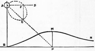 |
| Fig. 10. |
In measuring the candle-power of arc lamps it is necessary to have some arrangement by which the brightness of the rays proceeding from the arc in different directions can be measured. For this purpose the lamp may be suspended from a support, and a radial arm arranged to carry three mirrors, so that in whatever position the arm may be placed, it gathers light proceeding at one particular angle above or below the horizon from the arc, and this light is reflected out finally in a constant horizontal direction. An easily-arranged experiment enables us to determine the constant loss of light by reflection at all the mirrors, since that reflection always takes place at 45°. The ray thrown out horizontally can then be compared with that from any standard source of light by means of a fixed photometer, and by sweeping round the radial arm the photometric or illuminating curve of the arc lamp can be obtained. From this we can at once determine the nature of the illumination which would be produced on a horizontal surface if the arc lamp were suspended at a given distance above it. Let A (fig. 10) be an arc lamp placed at a height h( = AB) above a horizontal plane. Let ACD be the illuminating power curve of the arc, and hence AC the candle-power in a direction AP. The illumination (I) or brightness on the horizontal plane at P is equal to
In measuring the brightness of arc lamps, it’s important to have a system that allows us to measure the intensity of the light rays coming from the arc in various directions. To do this, the lamp can be hung from a support with a radial arm fitted with three mirrors. No matter how the arm is positioned, it captures light coming from a specific angle above or below the horizon from the arc, and this light is reflected out consistently in a horizontal direction. A straightforward experiment helps us figure out the constant loss of light due to reflection at all the mirrors, since this reflection always happens at a 45° angle. The ray emitted horizontally can then be compared with light from any standard source using a fixed photometer. By moving the radial arm around, we can create the photometric or illuminating curve of the arc lamp. From this, we can immediately determine the kind of illumination that would be produced on a horizontal surface if the arc lamp were hung at a certain height above it. Let A (fig. 10) be an arc lamp positioned at a height h (= AB) above a horizontal plane. Let ACD represent the illuminating power curve of the arc, making AC the candle-power in the direction AP. The illumination (I) or brightness on the horizontal plane at point P is equal to
AC cos APM/(AP)2 = FC/(h2 + x2), where x = BP.
AC cos APM/(AP)2 = FC/(h2 + x2), where x = BP.
 |
| Fig. 11. |
Hence if the candle-power curve of the arc and its height above the surface are known, we can describe a curve BMN, whose ordinate PM will denote the brightness on the horizontal surface at any point P. It is easily seen that this ordinate must have a maximum value at some point. This brightness is best expressed in candle-feet, taking the unit of illumination to be that given by a standard candle on a white surface at a distance of 1 ft. If any number of arc lamps are placed above a horizontal plane, the brightness at any point can be calculated by adding together the illuminations due to each respectively.
Hence, if we know the candle-power curve of the arc and its height above the surface, we can describe a curve BMN, where the ordinate PM represents the brightness on the horizontal surface at any point P. It's clear that this ordinate must reach a maximum value at some point. This brightness is best expressed in candle-feet, with the unit of illumination defined by a standard candle on a white surface at a distance of 1 ft. If multiple arc lamps are positioned above a horizontal plane, the brightness at any point can be calculated by adding together the illuminations from each lamp individually.
The process of delineating the photometric or polar curve of intensity for an arc lamp is somewhat tedious, but the curve has the advantage of showing exactly the distribution of light in different directions. When only the mean spherical or mean hemispherical candle-power is required the process can be shortened by employing an integrating photometer such as that of C. P. Matthews (Trans. Amer. Inst. Elec. Eng., 1903, 19, p. 1465), or the lumen-meter of A. E. Blondel which enables us to determine at one observation the total flux of light from the arc and therefore the mean spherical candle-power per watt.
The process of mapping out the photometric or polar curve of intensity for an arc lamp can be a bit tedious, but the curve effectively shows how light is distributed in different directions. If you only need the average spherical or average hemispherical candlepower, you can speed things up by using an integrating photometer like the one by C. P. Matthews (Trans. Amer. Inst. Elec. Eng., 1903, 19, p. 1465) or the lumen-meter by A. E. Blondel, which allows us to measure the total light flux from the arc in one go and thus determine the average spherical candlepower per watt.
 |
| Fig. 12. |
In the use of arc lamps for street and public lighting, the question of the distribution of light on the horizontal surface is all-important. In order that street surfaces may be well lighted, the minimum illumination should Street arc lighting. not fall below 0.1 candle-foot, and in general, in well-lighted streets, the maximum illumination will be 1 candle-foot and upwards. By means of an illumination photometer, such as that of W. H. Preece and A. P. Trotter, it is easy to measure the illumination in candle-feet at any point in a street surface, and to plot out a number of contour lines of equal illumination. Experience has shown that to obtain satisfactory results the lamps must be placed on a high mast 20 or 25 ft. above the roadway surface. These posts are now generally made of cast iron in various ornamental forms (fig. 11), the necessary conductors for conveying the current up to the lamp being taken 664 inside the iron mast. (The pair of incandescent lamps halfway down the standard are for use in the middle of the night, when the arc lamp would give more light than is required; they are lighted by an automatic switch whenever the arc is extinguished.) The lamp itself is generally enclosed in an opalescent spherical globe, which is woven over with wire-netting so that in case of fracture the pieces may not cause damage. The necessary trimming, that is, the replacement of carbons, is effected either by lowering the lamp or, preferably, by carrying round a portable ladder enabling the trimmer to reach it. For the purpose of public illumination it is very usual to employ a lamp taking 10 amperes, and therefore absorbing about 500 watts. Such a lamp is called a 500-watt arc lamp, and it is found that a satisfactory illumination is given for most street purposes by placing 500-watt arc lamps at distances varying from 40 to 100 yds., and at a height of 20 to 25 ft. above the roadway. The maximum candle-power of a 500-watt arc enclosed in a roughened or ground-glass globe will not exceed 1500 candles, and that of a 6.8-ampere arc (continuous) about 900 candles. If, however, the arc is an enclosed arc with double globes, the absorption of light would reduce the effective maximum to about 200 c.p. and 120 c.p. respectively. When arc lamps are placed in public thoroughfares not less than 40 yds. apart, the illumination anywhere on the street surface is practically determined by the two nearest ones. Hence the total illumination at any point may be obtained by adding together the illuminations due to each arc separately. Given the photometric polar curves or illuminating-power curves of each arc taken outside the shade or globe, we can therefore draw a curve representing the resultant illumination on the horizontal surface. It is obvious that the higher the lamps are placed, the more uniform is the street surface illumination, but the less its average value; thus two 10-ampere arcs placed on masts 20 ft. above the road surface and 100 ft. apart will give a maximum illumination of about 1.1 and a minimum of about 0.15 candle-feet in the interspace (fig 12). If the lamps are raised on 40-ft. posts the maximum illumination will fall to 0.3, and the minimum will rise to 0.2. For this reason masts have been employed as high as 90 ft. In docks and railway yards high masts (50 ft.) are an advantage, because the strong contrasts due to shadows of trucks, carts, &c., then become less marked, but for street illumination they should not exceed 30 to 35 ft. in height. Taking the case of 10-ampere and 6.8-ampere arc lamps in ordinary opal shades, the following figures have been given by Trotter as indicating the nature of the resultant horizontal illumination:—
In using arc lamps for street and public lighting, the way light is distributed on the ground is extremely important. To ensure streets are well-lit, the minimum illumination should be at least 0.1 candle-foot, while in well-lit areas, the maximum should be 1 candle-foot or more. Using an illumination photometer, like the one designed by W. H. Preece and A. P. Trotter, it’s straightforward to measure the light in candle-feet at any spot on the street and to map out several contour lines of equal light. Experience has shown that to achieve effective results, the lamps should be mounted on tall masts, 20 to 25 feet above the street. These posts are usually made of cast iron in various decorative styles (fig. 11), with the necessary wiring to deliver power to the lamp running inside the metal mast. (The pair of incandescent lamps positioned halfway down the standard are used during the night when the arc lamp provides more light than necessary; they turn on automatically when the arc is off.) The lamp itself is typically enclosed in a frosted spherical globe, which is covered with wire mesh to prevent injury in case of breakage. Routine maintenance, like changing the carbons, can be done by lowering the lamp or, more commonly, by using a portable ladder that allows the worker to reach it. For public lighting, a lamp that draws 10 amperes and consumes about 500 watts is very common. This type of lamp is referred to as a 500-watt arc lamp, providing satisfactory brightness for most street applications when placed 40 to 100 yards apart and 20 to 25 feet above the road. The maximum candlepower of a 500-watt arc inside a roughened or frosted globe is around 1,500 candles, while a 6.8-ampere arc produces about 900 candles. However, if the arc is in an enclosed setup with double globes, light absorption reduces the effective maximum to about 200 candela and 120 candela for each type, respectively. When arc lamps are positioned at least 40 yards apart on public roads, the illumination on the street is mostly influenced by the two closest lamps. Therefore, the overall brightness at any point can be calculated by adding the brightness from each arc. With the photometric polar curves or illuminating-power curves of each arc measured outside the shade or globe, we can draw a curve that indicates the resulting illumination on the horizontal surface. It's clear that the higher the lamps are installed, the more evenly the street is lit, but the average illumination value decreases; for instance, two 10-ampere arcs on masts 20 feet high and 100 feet apart will yield a maximum illumination of about 1.1 candle-feet and a minimum of about 0.15 candle-feet in between (fig 12). If the lamps are raised to 40-foot posts, the maximum illumination drops to 0.3, and the minimum rises to 0.2. Because of this, masts as tall as 90 feet have been used. In docks and railway yards, taller masts (50 feet) are beneficial since the strong shadows cast by vehicles and equipment become less drastic, but for street lighting, heights should not exceed 30 to 35 feet. According to Trotter, the following figures summarize the horizontal illumination resulting from 10-ampere and 6.8-ampere arc lamps in standard opal shades:—
| Arc Current in Amperes. | Height above Road in Feet. | Distance apart in Feet. | Horizontal Illumination in Candle-Feet. | |
| Maximum. | Minimum. | |||
| 10 | 20 | 120 | 1.85 | 0.12 |
| 10 | 25 | 120 | 1.17 | 0.15 |
| 10 | 40 | 120 | 0.5 | 0.28 |
| 6.8 | 20 | 90 | 1.1 | 0.21 |
| 6.8 | 40 | 120 | 0.3 | 0.17 |
As regards distance apart, a very usual practice is to place the lamps at spaces equal to six to ten times their height above the road surface. Blondel (Electrician, 35, p. 846) gives the following rule for the height (h) of the arc to afford the maximum illumination at a distance (d) from the foot of the lamp-post, the continuous current arc being employed:—
As for the distance between them, a common practice is to position the lamps at intervals of six to ten times their height above the road. Blondel (Electrician, 35, p. 846) provides this guideline for the height (h) of the arc to achieve the best illumination at a distance (d) from the base of the lamp-post, using the continuous current arc:—
| For naked arc | h = 0.95 d. |
| ” arc in rough glass globe | h = 0.85 d. |
| ” ” opaline glob | h = ” |
| ” ” opal globe | h = 0.5 d. |
| ” ” holophane globe | h = 0.5 d. |
These figures show that the distribution of light on the horizontal surface is greatly affected by the nature of the enclosing globe. For street illumination naked arcs, although sometimes employed in works and factory yards, are entirely unsuitable, since the result produced on the eye by the bright point of light is to paralyse a part of the retina and contract the pupil, hence rendering the eye less sensitive when directed on feebly illuminated surfaces. Accordingly, diffusing globes have to be employed. It is usual to place the arc in the interior of a globe of from 12 to 18 in. in diameter. This may be made of ground glass, opal glass, or be a dioptric globe such as the holophane. The former two are strongly absorptive, as may be seen from the results of experiments by Guthrie and Redhead. The following table shows the astonishing loss of light due to the use of opal globes:—
These figures show that the way light is spread over a horizontal surface is significantly influenced by the type of globe surrounding it. For street lighting, bare arcs, although sometimes used in workplaces and factory yards, are completely inappropriate, as the intense point of light can overwhelm part of the retina and shrink the pupil, making the eye less responsive when looking at dimly lit surfaces. Therefore, diffusing globes must be used. Typically, the arc is placed inside a globe that ranges from 12 to 18 inches in diameter. This can be made from ground glass, opal glass, or a dioptric globe like the holophane. The first two types absorb a lot of light, as shown by experiments conducted by Guthrie and Redhead. The following table illustrates the surprising loss of light caused by using opal globes:—
| Naked Arc. | Arc in Clear Globe. | Arc in Rough Glass Globe. | Arc in Opal Globe. | |
| Mean spherical c.p. | 319 | 235 | 160 | 144 |
| Mean hemispherical c.p. | 450 | 326 | 215 | 138 |
| Percentage value of transmitted light | 100 | 53 | 23 | 19 |
| Percentage absorption | 0 | 47 | 77 | 81 |
By using Trotter’s, Fredureau’s or the holophane globe, the light may be so diffused that the whole globe appears uniformly luminous, and yet not more than 20% of the light is absorbed. Taking the absorption of an ordinary opal globe into account, a 500-watt arc does not usually give more than 500 c.p. as a maximum candle-power. Even with a naked 500-watt arc the mean spherical candle-power is not generally more than 500 c.p., or at the rate of 1 c.p. per watt. The maximum candle-power for a given electrical power is, however, greatly dependent on the current density in the carbon, and to obtain the highest current density the carbons must be as thin as possible. (See T. Hesketh, “Notes on the Electric Arc,” Electrician, 39, p. 707.)
By using Trotter’s, Fredureau’s, or the holophane globe, the light can be spread out so that the entire globe looks evenly lit, and yet only about 20% of the light gets absorbed. Considering the absorption of a standard opal globe, a 500-watt arc usually produces a maximum of only 500 candle-power. Even with an exposed 500-watt arc, the average spherical candle-power typically doesn't exceed 500 candle-power, which is about 1 candle-power per watt. However, the highest candle-power for a specific electrical power is largely influenced by the current density in the carbon, and to achieve the best current density, the carbons need to be as thin as possible. (See T. Hesketh, “Notes on the Electric Arc,” Electrician, 39, p. 707.)
For the efficiency of arcs of various kinds, expressed by the mean hemispherical candle power per ampere and per watt expended in the arc, the following figures were given by L. Andrews (“Long-flame Arc Lamps,” Journal Inst. Elec. Eng., 1906, 37, p. 4).
For the efficiency of different types of arcs, measured by the average hemispherical candle power per ampere and per watt used in the arc, the following figures were provided by L. Andrews (“Long-flame Arc Lamps,” Journal Inst. Elec. Eng., 1906, 37, p. 4).
| Candle-power per ampere. | Candle-power per watt. | |
| Ordinary open carbon arc | 82 | 1.54 |
| Enclosed carbon arc | 55 | 0.77 |
| Chemical carbon or flame arc | 259 | 5.80 |
| High voltage inclined carbon arc | 200 | 2.24 |
It will be seen that the flame arc lamp has an enormous advantage over other types in the light yielded for a given electric power consumption.
It’s clear that the flame arc lamp has a huge advantage over other types when it comes to the amount of light produced for a given amount of electric power used.
The practical employment of the electric arc as a means of illumination is dependent upon mechanism for automatically keeping two suitable carbon rods in the proper position, and moving them so as to enable a steady arc to be Arc lamp mechanism. maintained. Means must be provided for holding the carbons in line, and when the lamp is not in operation they must fall together, or come together when the current is switched on, so as to start the arc. As soon as the current passes, they must be moved slightly apart, and gripped in position immediately the current reaches its right value, being 665 moved farther apart if the current increases in strength, and brought together if it decreases. Moreover, it must be possible for a considerable length of carbon to be fed through the lamp as required.
The practical use of the electric arc for lighting relies on a mechanism that automatically keeps two suitable carbon rods in the right position and moves them to ensure a steady arc can be maintained. Arc lamp system. There must be a way to keep the carbons aligned, and when the lamp is off, they should come together, or touch when the current is turned on, to start the arc. Once the current flows, they need to be moved slightly apart and held in place as soon as the current reaches the appropriate level, being moved farther apart if the current increases and brought closer if it decreases. Additionally, it should be possible to feed a significant length of carbon through the lamp as needed.
 |
| Fig. 13 |
 |
| Fig. 14 |
One early devised form of arc-lamp mechanism was a system of clockwork driven by a spring or weight, which was started and stopped by the action of an electromagnet; in modern lighthouse lamps a similar mechanism is still employed. W. E. Staite (1847), J. B. L. Foucault (1849), V. L. M. Serrin (1857), J. Duboscq (1858), and a host of later inventors, devised numerous forms of mechanical and clockwork lamps. The modern self-regulating type may be said to have been initiated in 1878 by the differential lamp of F. von Hefner-Alteneck, and the clutch lamp of C. F. Brush. The general principle of the former may be explained as follows: There are two solenoids, placed one above the other. The lower one, of thick wire, is in series with the two carbon rods forming the arc, and is hence called the series coil. Above this there is placed another solenoid of fine wire, which is called the shunt coil. Suppose an iron rod to be placed so as to be partly in one coil and partly in another; then when the coils are traversed by currents, the iron core will be acted upon by forces tending to pull it into these solenoids. If the iron core be attached to one end of a lever, the other end of which carries the upper carbon, it will be seen that if the carbons are in contact and the current is switched on, the series coil alone will be traversed by the current, and its magnetic action will draw down the iron core, and therefore pull the carbons apart and strike the arc. The moment the carbons separate, there will be a difference of potential between them, and the shunt coil will then come into action, and will act on the core so as to draw the carbons together. Hence the two solenoids act in opposition to each other, one increasing and the other diminishing the length of the arc, and maintaining the carbons in the proper position. In the lamp of this type the upper carbon is in reality attached to a rod having a side-rack gearing, with a train of wheels governed by a pendulum. The action of the series coil on the mechanism is to first lock or stop the train, and then lift it as a whole slightly. This strikes the arc. When the arc is too long, the series coil lowers the gear and finally releases the upper carbon, so that it can run down by its own weight. The principle of a shunt and series coil operating on an iron core in opposition is the basis of the mechanism of a number of arc lamps. Thus the lamp invented by F. Krizik and L. Piette, called from its place of origin the Pilsen lamp, comprises an iron core made in the shape of a double cone or spindle (fig. 13), which is so arranged in a brass tube that it can move into or out of a shunt and series coil, wound the one with fine and the other with thick insulated wire, and hence regulate the position of the carbon attached to it. The movement of this core is made to feed the carbons directly without the intervention of any clockwork, as in the case of the Hefner-Alteneck lamp. In the clutch-lamp mechanism the lower carbon is fixed, and the upper carbon rests upon it by its own weight and that of its holder. The latter consists of a long rod passing through guides, and is embraced somewhere by a ring capable of being tilted or lifted by a finger attached to the armature of an electromagnet the coils of which are in series with the arc. When the current passes through the magnet it attracts the armature, and by tilting the ring lifts the upper carbon-holder and hence strikes the arc. If the current diminishes in value, the upper carbon drops a little by its own weight, and the feed of the lamp is thus effected by a series of small lifts and drops of the upper carbon (fig. 14). Another element sometimes employed in arc-lamp mechanism is the brake-wheel regulator. This is a feature of one form of the Brockie and of the Crompton-Pochin lamps. In these the movement of the carbons is effected by a cord or chain which passes over a wheel, or by a rack geared with the brake wheel. When no current is passing through the lamp, the wheel is free to move, and the carbons fall together; but when the current is switched on, the chain or cord passing over the brake wheel, or the brake wheel itself is gripped in some way, and at the same time the brake wheel is lifted so that the arc is struck.
One early design of an arc-lamp mechanism was a clockwork system powered by a spring or weight, which was started and stopped by an electromagnet. A similar mechanism is still used in modern lighthouse lamps. W. E. Staite (1847), J. B. L. Foucault (1849), V. L. M. Serrin (1857), J. Duboscq (1858), and many later inventors created various types of mechanical and clockwork lamps. The modern self-regulating type can be traced back to 1878 with the differential lamp by F. von Hefner-Alteneck and the clutch lamp by C. F. Brush. The basic principle of the former works like this: There are two solenoids, one above the other. The lower one, made of thick wire, is connected in series with the two carbon rods forming the arc, and is called the series coil. Above this is another solenoid made of fine wire, known as the shunt coil. If you place an iron rod so that it's partly in one coil and partly in the other, when the coils have current flowing through them, the iron core will experience forces pulling it into the coils. If the iron core is attached to one end of a lever, which has the upper carbon on the other end, when the carbons contact and the current is turned on, only the series coil will have current flowing through it, and its magnetic force will pull down the iron core, which pulls the carbons apart and ignites the arc. Once the carbons separate, there will be a potential difference between them, and the shunt coil will activate, acting on the core to pull the carbons back together. Thus, the two solenoids work against each other, one increasing and the other decreasing the arc length, keeping the carbons in the correct position. In this type of lamp, the upper carbon is actually connected to a rod with a side-rack gearing, driven by a series of gears controlled by a pendulum. The series coil first locks or stops the gear train and then slightly lifts it as a whole. This creates the arc. If the arc gets too long, the series coil lowers the gear and eventually releases the upper carbon, allowing it to drop due to its weight. The mechanism of several arc lamps is based on the operation of a shunt and series coil on an iron core in opposition. For example, the lamp developed by F. Krizik and L. Piette, known as the Pilsen lamp after its place of origin, has an iron core shaped like a double cone or spindle (fig. 13). This core is positioned inside a brass tube, allowing it to move in and out of a shunt and series coil, which are wound with fine and thick insulated wire respectively, thus regulating the position of the attached carbon. The core's movement feeds the carbons directly without needing any clockwork, unlike the Hefner-Alteneck lamp. In the clutch lamp mechanism, the lower carbon is fixed, while the upper carbon rests on it due to its weight and that of its holder. The holder consists of a long rod that passes through guides and is surrounded by a ring that can be tilted or lifted by a finger connected to the armature of an electromagnet, which is wired in series with the arc. When current flows through the magnet, it pulls the armature, tilting the ring to lift the upper carbon holder, thus igniting the arc. If the current decreases, the upper carbon drops a bit due to its weight, and the lamp feeds itself through a series of small lifts and drops of the upper carbon (fig. 14). Another component sometimes used in arc-lamp mechanisms is the brake-wheel regulator. This feature is found in one design of the Brockie and Crompton-Pochin lamps. In these models, the movement of the carbons is controlled by a cord or chain over a wheel, or by a rack connected to the brake wheel. When no current is passing through the lamp, the wheel can move freely, causing the carbons to fall together, but when the current is turned on, the chain or cord running over the brake wheel (or the brake wheel itself) is gripped, and at the same moment, the brake wheel is lifted, initiating the arc.
Although countless forms of self-regulating device have been invented for arc lamps, nothing has survived the test of time so well as the typical mechanisms which work with carbon rods in one line, one or both rods being moved by a controlling apparatus as required. The early forms of semi-incandescent arc lamp, such as those of R. Werdermann and others, have dropped out of existence. These were not really true arc lamps, the light being produced by the incandescence of the extremity of a thin carbon rod pressed against a larger rod or block. The once famous Jablochkoff candle, invented in 1876, consisted of two carbon rods about 4 mm. in diameter, placed parallel to each other and separated by a partition of kaolin, steatite or other refractory non-conductor. Alternating currents were employed, and the candle was set in operation by a match or starter of high-resistance carbon paste which connected the tips of the rods. When this burned off, a true arc was formed between the parallel carbons, the separator volatilizing as the carbons burned away. Although much ingenuity was expended on this system of lighting between 1877 and 1881, it no longer exists. One cause of its disappearance was its relative inefficiency in light-giving power compared with other forms of carbon arc taking the same amount of power, and a second equally important reason was the waste in carbons. If the arc of the electric candle was accidentally blown out, no means of relighting existed; hence the great waste in half-burnt candles. H. Wilde, J. C. Jamin, J. Rapieff and others endeavoured to provide a remedy, but without success.
Although many kinds of self-regulating devices have been created for arc lamps, nothing has stood the test of time quite like the typical mechanisms that use carbon rods aligned in one line, with one or both rods adjusted by a control system as needed. The early types of semi-incandescent arc lamps, such as those made by R. Werdermann and others, are no longer in use. These weren’t really true arc lamps since the light was produced by the incandescence at the tip of a thin carbon rod pressed against a larger rod or block. The once-popular Jablochkoff candle, invented in 1876, consisted of two carbon rods about 4 mm in diameter, placed parallel to each other and separated by a barrier of kaolin, steatite, or another heat-resistant non-conductive material. Alternating currents were used, and the candle was activated by a match or a starter made of high-resistance carbon paste that connected the tips of the rods. Once it burned away, a real arc was created between the parallel carbon rods, and the separator vaporized as the carbon burned. Even though a lot of creativity went into this lighting system between 1877 and 1881, it has since disappeared. One reason for its decline was its relatively low efficiency in terms of light output compared to other types of carbon arc lamps that used the same amount of power, and another significant reason was the waste of carbon. If the arc of the electric candle was accidentally extinguished, there was no way to reignite it, leading to the waste of partially burned candles. H. Wilde, J. C. Jamin, J. Rapieff, and others tried to find a solution, but none succeeded.
It is impossible to give here detailed descriptions of a fraction of the arc-lamp mechanisms devised, and it must suffice to indicate the broad distinctions between various types. (1) Arc lamps may be either continuous-current or alternating-current lamps. For outdoor public illumination the former are greatly preferable, as owing to the form of the illuminating power-curve they send the light down on the road surface, provided the upper carbon is the positive one. For indoor, public room or factory lighting, inverted arc lamps are sometimes employed. In this case the positive carbon is the lower one, and the lamp is carried in an inverted metallic reflector shield, so that the light is chiefly thrown up on the ceiling, whence it is diffused all round. The alternating-current arc is not only less efficient in mean spherical candle-power per watt of electric power absorbed, but its distribution of light is disadvantageous for street purposes. Hence when arc lamps have to be worked off an alternating-current circuit for public lighting it is now usual to make use of a rectifier, which rectifies the alternating current into an unidirectional though pulsating current. (2.) Arc lamps may be also classified, as above described, into open or enclosed arcs. The enclosed arc can be made to burn for 200 hours with one pair of carbons, whereas open-arc lamps are usually only able to work, 8, 16 or 32 hours without recarboning, even when fitted with double carbons. (3) Arc lamps are further divided into focussing and non-focussing lamps. In the former the lower carbon is made to move up as the upper carbon moves down, and the arc is therefore maintained at the same level. This is advisable for arcs included in a globe, and absolutely necessary in the case of lighthouse lamps and lamps for optical purposes. (4) Another subdivision is into hand-regulated and self-regulating lamps. In the hand-regulated arcs the carbons are moved by a screw attachment as required, as in some forms of search-light lamp and lamps for optical lanterns. The carbons in large search-light lamps are usually placed horizontally. The self-regulating lamps may be classified into groups depending upon the nature of the regulating appliances. In some cases the regulation is controlled only by a series coil, and in others only by a shunt coil. Examples of the former are the original Gülcher and Brush clutch lamp, and some modern enclosed arc lamps; and of the latter, the Siemens “band” lamp, and the Jackson-Mensing lamp. In series coil lamps the variation of the current in the coil throws into or out of action the carbon-moving mechanism; in shunt coil lamps the variation in voltage between the carbons is caused to effect the same changes. Other types of lamp involve the use both of shunt and series coils acting against each other. A further classification of the self-regulating lamps may be found in the nature of the carbon-moving mechanism. This may be some modification of the Brush ring clutch, hence called clutch lamps; or some variety of brake wheel, as employed in Brockie and Crompton lamps; or else some form of electric motor is thrown into or out of action and effects the necessary changes. In many cases the arc-lamp mechanism is provided with a dash-pot, or contrivance in which a piston moving nearly air-tight in a cylinder prevents sudden jerks in the motion of the mechanism, and thus does away with the “hunting” or rapid up-and-down movements to which some varieties of clutch mechanism are liable. One very 666 efficient form is illustrated in the Thomson lamp and Brush-Vienna lamp. In this mechanism a shunt and series coil are placed side by side, and have iron cores suspended to the ends of a rocking arm held partly within them. Hence, according as the magnetic action of the shunt or series coil prevails, the rocking arm is tilted backwards or forwards. When the series coil is not in action the motion is free, and the upper carbon-holder slides down, or the lower one slides up, and starts the arc. The series coil comes into action to withdraw the carbons, and at the same time locks the mechanism. The shunt coil then operates against the series coil, and between them the carbon is fed forwards as required. The control to be obtained is such that the arc shall never become so long as to flicker and become extinguished, when the carbons would come together again with a rush, but the feed should be smooth and steady, the position of the carbons responding quickly to each change in the current.
It’s not possible to provide detailed descriptions of all the different arc-lamp mechanisms that have been created, so I will just highlight the key differences between the various types. (1) Arc lamps can be either continuous-current or alternating-current lamps. For outdoor public lighting, continuous-current lamps are much better, as their light distribution focuses down on the road surface, assuming the upper carbon is the positive one. For indoor spaces like public rooms or factories, inverted arc lamps are sometimes used. In this setup, the positive carbon is at the bottom, and the lamp is placed in an inverted metallic reflector shield, directing the light primarily onto the ceiling, from where it spreads out. The alternating-current arc is less efficient in terms of average candle power per watt consumed and has a less favorable light distribution for street lighting. Therefore, when arc lamps need to be powered by an alternating-current circuit for public lighting, it is now common to use a rectifier that converts the alternating current into a unidirectional but pulsating current. (2.) Arc lamps can also be categorized, as mentioned above, into open or enclosed arcs. An enclosed arc can operate for up to 200 hours with one pair of carbons, while open-arc lamps typically only last 8, 16, or 32 hours without needing new carbons, even with double carbons installed. (3) Arc lamps are further divided into focusing and non-focusing lamps. In focusing lamps, the lower carbon moves up as the upper carbon moves down, keeping the arc at the same level. This is recommended for arcs enclosed in a globe and is essential for lighthouse lamps and lamps used for optical purposes. (4) Another category separates hand-regulated and self-regulating lamps. In hand-regulated arcs, the carbons are adjusted by a screw attachment as needed, like in some types of searchlight lamps and optical lanterns. The carbons in large searchlight lamps are usually positioned horizontally. Self-regulating lamps can be grouped based on the type of regulation they use. In some cases, regulation is controlled solely by a series coil, while in others, it’s controlled by a shunt coil. Examples of series coil lamps include the original Gülcher and Brush clutch lamp, as well as some modern enclosed arc lamps; examples of shunt coil lamps are the Siemens “band” lamp and the Jackson-Mensing lamp. In series coil lamps, current variation in the coil activates or deactivates the carbon-moving mechanism; in shunt coil lamps, voltage variation between the carbons causes similar changes. Other lamp types combine both shunt and series coils working against each other. A further classification of self-regulating lamps can be made based on the carbon-moving mechanism. This might be a variation of the Brush ring clutch, hence called clutch lamps; or a type of brake wheel, as used in Brockie and Crompton lamps; or some form of electric motor that turns on or off to make the necessary adjustments. In many instances, the arc-lamp mechanism is equipped with a dash-pot, a device where a piston moves in a nearly airtight cylinder to prevent sudden jolts in the mechanism, thereby avoiding the “hunting” or rapid up-and-down movements that can occur with some clutch mechanisms. One very effective design is shown in the Thomson lamp and Brush-Vienna lamp. Here, the shunt and series coils are positioned side by side, with iron cores suspended from the ends of a rocking arm held partly within them. Depending on whether the magnetic force of the shunt or series coil is stronger, the rocking arm tilts forward or backward. When the series coil is inactive, the motion is free, allowing the upper carbon-holder to slide down or the lower one to slide up, starting the arc. The series coil then activates to retract the carbons and simultaneously locks the mechanism. The shunt coil then works against the series coil, moving the carbon forward as needed. The control achieved ensures that the arc never becomes so long that it flickers and goes out, which would cause the carbons to rush together again, but rather feeds smoothly and steadily, with the position of the carbons responding quickly to any changes in the current.
The introduction of enclosed arc lamps was a great improvement, in consequence of the economy effected in the consumption of carbon and in the cost of labour for trimming. A well-known and widely used form of enclosed arc lamp is the Jandus lamp, which in large current form can be made to burn for two hundred hours without recarboning, and in small or midget form to burn for forty hours, taking a current of two amperes at 100 volts. Such lamps in many cases conveniently replace large sizes of incandescent lamps, especially for shop lighting, as they give a whiter light. Great improvements have also been made in inclined carbon arc lamps. One reason for the relatively low efficiency of the usual vertical rod arrangement is that the crater can only radiate laterally, since owing to the position of the negative carbon no crater light is thrown directly downwards. If, however, the carbons are placed in a downwards slanting position at a small angle like the letter V and the arc formed at the bottom tips, then the crater can emit downwards all the light it produces. It is found, however, that the arc is unsteady unless a suitable magnetic field is employed to keep the arc in position at the carbon tips. This method has been adopted in the Carbone arc, which, by the employment of inclined carbons, and a suitable electromagnet to keep the true arc steady at the ends of the carbons, has achieved considerable success. One feature of the Carbone arc is the use of a relatively high voltage between the carbons, their potential difference being as much as 85 volts.
The introduction of enclosed arc lamps was a significant improvement because it reduced the amount of carbon used and the labor costs for maintenance. A well-known and commonly used type of enclosed arc lamp is the Jandus lamp, which in its larger version can operate for two hundred hours without needing a replacement of the carbon, and in its smaller or midget version can run for forty hours, drawing a current of two amperes at 100 volts. These lamps often serve as a convenient replacement for larger incandescent lamps, particularly for shop lighting, since they emit a whiter light. Major advancements have also been made in inclined carbon arc lamps. One reason for the lower efficiency of the typical vertical rod setup is that the crater can only radiate light sideways, as the negative carbon's position prevents light from being directed downward. However, if the carbons are angled downward slightly like a V-shape and the arc forms at the tips, the crater can produce and emit all its light downward. It has been found, though, that the arc becomes unstable unless a proper magnetic field is used to keep it in place at the carbon tips. This approach has been implemented in the Carbone arc, which, by utilizing inclined carbons and an appropriate electromagnet to maintain the steady arc at the ends of the carbons, has been quite successful. One notable aspect of the Carbone arc is the application of a relatively high voltage across the carbons, with a potential difference reaching up to 85 volts.
Arc lamps may be arranged either (i.) in series, (ii.) in parallel or (iii.) in series parallel. In the first case a number, say 20, may be traversed by the same current, in that case supplied at a pressure of 1000 volts. Each must have Arrangement. a magnetic cut-out, so that if the carbons stick together or remain apart the current to the other lamps is not interrupted, the function of such a cut-out being to close the main circuit immediately any one lamp ceases to pass current. Arc lamps worked in series are generally supplied with a current from a constant current dynamo, which maintains an invariable current of, say 10 amperes, independently of the number of lamps on the external circuit. If the lamps, however, are worked in series off a constant potential circuit, such as one supplying at the same time incandescent lamps, provision must be made by which a resistance coil can be substituted for any one lamp removed or short-circuited. When lamps are worked in parallel, each lamp is independent, but it is then necessary to add a resistance in series with the lamp. By special devices three lamps can be worked in series of 100 volt circuits. Alternating-current arc lamps can be worked off a high-tension circuit in parallel by providing each lamp with a small transformer. In some cases the alternating high-tension current is rectified and supplied as a unidirectional current to lamps in series. If single alternating-current lamps have to be worked off a 100 volt alternating-circuit, each lamp must have in series with it a choking coil or economy coil, to reduce the circuit pressure to that required for one lamp. Alternating-current lamps take a larger effective current, and work with a less effective or virtual carbon P.D., than continuous current arcs of the same wattage.
Arc lamps can be set up in one of three ways: (i.) in series, (ii.) in parallel, or (iii.) in a series-parallel combination. In the first setup, say 20 lamps can be connected to the same current, which is supplied at a voltage of 1000 volts. Each lamp needs a magnetic cut-out, so if one lamp's carbons stick together or stay apart, the current to the other lamps will not be interrupted. The cut-out's role is to close the main circuit as soon as any lamp stops passing current. Arc lamps connected in series are typically powered by a constant current dynamo, which keeps a steady current of about 10 amperes, no matter how many lamps are on the circuit. However, if the lamps are connected in series from a constant voltage circuit—like one that also supplies incandescent lamps—there needs to be a way to replace any lamp that is removed or short-circuited with a resistance coil. When lamps are connected in parallel, each one operates independently, but you still need to add a resistance in series with each lamp. With certain devices, three lamps can be run in series on 100-volt circuits. Alternating-current arc lamps can be powered in parallel from a high-voltage circuit by using a small transformer for each lamp. In some cases, the alternating high-voltage current is rectified and supplied as direct current to lamps in series. If individual alternating-current lamps are used on a 100-volt circuit, each lamp must be paired with a choking coil or economy coil to lower the circuit voltage to what's needed for one lamp. Alternating-current lamps draw a higher effective current and operate with a lower effective or virtual carbon potential difference than continuous current arcs of the same wattage.
The cost of working public arc lamps is made up of several items. There is first the cost of supplying the necessary electric energy, then the cost of carbons and the labour of recarboning, and, lastly, an item due to depreciation Cost. and repairs of the lamps. An ordinary type of open 10 ampere arc lamp, burning carbons 15 and 9 mm. in diameter for the positive and negative, and working every night of the year from dusk to dawn, uses about 600 ft. of carbons per annum. If the positive carbon is 18 mm. and the negative 12 mm., the consumption of each size of carbon is about 70 ft. per 1000 hours of burning. It may be roughly stated that at the present prices of plain open arc-lamp carbons the cost is about 15s. per 1000 hours of burning; hence if such a lamp is burnt every night from dusk to midnight the annual cost in that respect is about £1, 10s. The annual cost of labour per lamp for trimming is in Great Britain from £2 to £3; hence, approximately speaking, the cost per annum of maintenance of a public arc lamp burning every night from dusk to midnight is about £4 to £5, or perhaps £6, per annum, depreciation and repairs included. Since such a 10 ampere lamp uses half a Board of Trade unit of electric energy every hour, it will take 1000 Board of Trade units per annum, burning every night from dusk to midnight; and if this energy is supplied, say at 1½d. per unit, the annual cost of energy will be about £6, and the upkeep of the lamp, including carbons, labour for trimming and repairs, will be about £10 to £11 per annum. The cost for labour and carbons is considerably reduced by the employment of the enclosed arc lamp, but owing to the absorption of light produced by the inner enclosing globe, and the necessity for generally employing a second outer globe, there is a lower resultant candle-power per watt expended in the arc. Enclosed arc lamps are made to burn without attention for 200 hours, singly on 100 volt circuits, or two in series on 200 volt circuits, and in addition to the cost of carbons per hour being only about one-twentieth of that of the open arc, they have another advantage in the fact that there is a more uniform distribution of light on the road surface, because a greater proportion of light is thrown out horizontally.
The cost of operating public arc lamps consists of several elements. First, there's the cost of providing the necessary electricity, then the expense of carbons and the labor for replacing them, and finally, there's a cost for depreciation and repairs of the lamps. A standard open 10 ampere arc lamp that uses carbons 15 mm and 9 mm in diameter for the positive and negative poles, and operates every night of the year from dusk to dawn, consumes about 600 feet of carbons annually. If the positive carbon is 18 mm and the negative is 12 mm, the consumption for each size is about 70 feet per 1000 hours of operation. Roughly speaking, at current prices for plain open arc lamp carbons, the cost is around 15 shillings per 1000 hours of operation; therefore, if such a lamp is used nightly from dusk to midnight, the annual cost for this would be about £1.10. The annual labor cost per lamp for maintenance in Great Britain ranges from £2 to £3; so, roughly, the total annual maintenance cost for a public arc lamp operating every night from dusk to midnight is about £4 to £5, or possibly £6, including depreciation and repairs. Since a 10 ampere lamp uses half a Board of Trade unit of electricity per hour, it will consume 1000 Board of Trade units per year if burned every night from dusk to midnight; and if this energy costs, say, 1½ pence per unit, the annual cost for electricity will be around £6. Therefore, the total upkeep of the lamp, including carbons, labor for trimming, and repairs, will be approximately £10 to £11 per year. The costs for labor and carbons are significantly lower with enclosed arc lamps, but due to the light absorption by the inner globe and the need for a second outer globe, there is a decrease in the resulting candle power per watt used in the arc. Enclosed arc lamps can operate unattended for 200 hours, either singly on 100 volt circuits or in pairs on 200 volt circuits, and in addition to the cost of carbons per hour being only about one-twentieth of that of open arcs, they also provide a more uniform distribution of light across the road surface because a greater proportion of light is emitted horizontally.
It has been found by experience that the ordinary type of open arc lamp with vertical carbons included in an opalescent globe cannot compete in point of cost with modern improvements in gas lighting as a means of street illumination. The violet colour of the light and the sharp shadows, and particularly the non-illuminated area just beneath the lamp, are grave disadvantages. The high-pressure flame arc lamp with inclined chemically treated carbons has, however, put a different complexion on matters. Although the treated carbons cost more than the plain carbons, yet there is a great increase of emitted light, and a 9-ampere flame arc lamp supplied with electric energy at 1½d. per unit can be used for 1000 hours at an inclusive cost of about £s to £6, the mean emitted illumination being at the rate of 4 c.p. per watt absorbed. In the Carbone arc lamp, the carbons are worked at an angle of 15° or 20° to each other and the arc is formed at the lower ends. If the potential difference of the carbons is low, say only 50-60 volts, the crater forms between the tips of the carbons and is therefore more or less hidden. If, however, the voltage is increased to 90-100 then the true flame of the arc is longer and is curved, and the crater forms at the exteme tip of the carbons and throws all its light downwards. Hence results a far greater mean hemispherical candle power (M.H.S.C.P.), so that whereas a 10-ampere 60 volt open arc gives at most 1200 M.H.S.C.P., a Carbone 10-ampere 85 volt arc will give 2700 M.H.S.C.P. Better results still can be obtained with impregnated carbons. But the flame arcs with impregnated carbons cannot be enclosed, so the consumption of carbon is greater, and the carbons themselves are more costly, and leave a greater ash on burning; hence more trimming is required. They give a more pleasing effect for street lighting, and their golden yellow globe of light is more useful than an equally costly plain arc of the open type. This improvement in efficiency is, however, accompanied by some disadvantages. The flame arc is very sensitive to currents of air and therefore has to be shielded from draughts by putting it under an “economizer” or chamber of highly refractory material which surrounds the upper carbon, or both carbon tips, if the arc is formed with inclined carbons. (For additional information on flame arc lamps see a paper by L. B. Marks and H. E. Clifford, Electrician, 1906, 57, p. 975.)
It has been found through experience that the standard open arc lamp with vertical carbons inside an opalescent globe cannot compete in cost with modern advancements in gas lighting for street illumination. The violet color of the light, the sharp shadows, and especially the dark area directly beneath the lamp are significant drawbacks. However, the high-pressure flame arc lamp with angled chemically treated carbons has changed the situation. Although treated carbons are more expensive than regular ones, they produce significantly more light. A 9-ampere flame arc lamp powered with electricity at 1½d. per unit can run for 1000 hours at a total cost of about £s to £6, with an average emitted illumination of 4 c.p. per watt consumed. In the Carbone arc lamp, the carbons are positioned at an angle of 15° or 20° to each other, and the arc is created at their lower ends. If the voltage difference between the carbons is low, around 50-60 volts, the crater forms between the tips of the carbons and is somewhat hidden. However, if the voltage is increased to 90-100, the true flame of the arc is longer and curved, with the crater forming at the extreme tip of the carbons and directing all its light downward. This results in a much higher mean hemispherical candle power (M.H.S.C.P.). So while a 10-ampere 60-volt open arc gives at most 1200 M.H.S.C.P., a Carbone 10-ampere 85-volt arc can produce 2700 M.H.S.C.P. Even better results can be achieved with impregnated carbons. However, flame arcs with impregnated carbons can't be enclosed, so they consume more carbon, the carbons are more expensive, and they leave more ash when burned, requiring more maintenance. They do create a more appealing effect for street lighting, and their golden-yellow glow is more beneficial than an equally priced plain open arc. This increase in efficiency does come with some drawbacks. The flame arc is very sensitive to air currents, so it needs to be shielded from drafts by placing it inside an “economizer” or chamber made of highly heat-resistant material that surrounds the upper carbon, or both carbon tips if the arc is formed with angled carbons. (For more information on flame arc lamps, see a paper by L. B. Marks and H. E. Clifford, Electrician, 1906, 57, p. 975.)
2. Incandescent Lamps.—Incandescent electric lighting, although not the first, is yet in one sense the most obvious method of utilizing electric energy for illumination. It was evolved from the early observed fact that a conductor is heated 667 when traversed by an electric current, and that if it has a high resistance and a high melting-point it may be rendered incandescent, and therefore become a source of light. Naturally every inventor turned his attention to the employment of wires of refractory metals, such as platinum or alloys of platinum-iridium, &c., for the purpose of making an incandescent lamp. F. de Moleyns experimented in 1841, E. A. King and J. W. Starr in 1845, J. J. W. Watson in 1853, and W. E. Staite in 1848, but these inventors achieved no satisfactory result. Part of their want of success is attributable to the fact that the problem of the economical production of electric current by the dynamo machine had not then been solved. In 1878 T. A. Edison devised lamps in which a platinum wire was employed as the light-giving agent, carbon being made to adhere round it by pressure. Abandoning this, he next directed his attention to the construction of an “electric candle,” consisting of a thin cylinder or rod formed of finely-divided metals, platinum, iridium, &c., mixed with refractory oxides, such as magnesia, or zirconia, lime, &c. This refractory body was placed in a closed vessel and heated by being traversed by an electric current. In a further improvement he proposed to use a block of refractory oxide, round which a bobbin of fine platinum or platinum-iridium wire was coiled. Every other inventor who worked at the problem of incandescent lighting seems to have followed nearly the same path of invention. Long before this date, however, the notion of employing carbon as a substance to be heated by the current had entered the minds of inventors; even in 1845 King had employed a small rod of plumbago as the substance to be heated. It was obvious, however, that carbon could only be so heated when in a space destitute of oxygen, and accordingly King placed his plumbago rod in a barometric vacuum. S. W. Konn in 1872, and S. A. Kosloff in 1875, followed in the same direction.
2. Incandescent Lamps.—Incandescent electric lighting, while not the very first method, is still the most straightforward way to use electric energy for light. It stemmed from the early observation that a conductor gets heated when an electric current passes through it, and if the conductor has high resistance and a high melting point, it can glow and therefore produce light. Naturally, inventors began exploring the use of wires made from heat-resistant metals like platinum or platinum-iridium alloys to create an incandescent lamp. F. de Moleyns experimented in 1841, E. A. King and J. W. Starr in 1845, J. J. W. Watson in 1853, and W. E. Staite in 1848, but none of these inventors had success. Part of their lack of success was due to the fact that the economical generation of electric current by the dynamo machine had not yet been figured out. In 1878, T. A. Edison created lamps using a platinum wire as the light source, with carbon pressed around it. He then shifted his focus to designing an “electric candle,” made of a thin cylinder or rod of finely divided metals, including platinum, iridium, and others, mixed with heat-resistant oxides like magnesia or zirconia, and lime. This heat-resistant material was placed in a sealed container and heated by electric current. In a further improvement, he proposed using a block of heat-resistant oxide with a coil of fine platinum or platinum-iridium wire wrapped around it. Other inventors working on incandescent lighting mostly followed a similar path. However, the idea of using carbon as a material to be heated by the current had already crossed the minds of inventors long before this; even in 1845, King had experimented with a small rod of graphite as the heated material. It was clear, though, that carbon could only be heated in an oxygen-free environment, so King put his graphite rod in a barometric vacuum. S. W. Konn in 1872 and S. A. Kosloff in 1875 took similar approaches.
No real success attended the efforts of inventors until it was finally recognized, as the outcome of the work by J. W. Swan, T. A. Edison, and, in a lesser degree, St. G. Lane Fox and W. E. Sawyer and A. Man, that the conditions Carbon filament lamp. of success were as follow: First, the substance to be heated must be carbon in the form of a thin wire rod or thread, technically termed a filament; second, this must be supported and enclosed in a vessel formed entirely of glass; third, the vessel must be exhausted as perfectly as possible; and fourth, the current must be conveyed into and out of the carbon filament by means of platinum wires hermetically sealed through the glass.
No real success came to the efforts of inventors until it was finally recognized, thanks to the work of J. W. Swan, T. A. Edison, and, to a lesser extent, St. G. Lane Fox, W. E. Sawyer, and A. Man, that the conditions for success were as follows: First, the material to be heated must be carbon in the form of a thin wire rod or thread, technically called a filament; second, this must be supported and enclosed in a vessel made entirely of glass; third, the vessel must be as completely exhausted as possible; and fourth, the current must be delivered into and out of the carbon filament using platinum wires that are sealed through the glass. Carbon light bulb.
One great difficulty was the production of the carbon filament. King, Sawyer, Man and others had attempted to cut out a suitably shaped piece of carbon from a solid block; but Edison and Swan were the first to show that the proper solution of the difficulty was to carbonize an organic substance to which the necessary form had been previously given. For this purpose cardboard, paper and ordinary thread were originally employed, and even, according to Edison, a mixture of lampblack and tar rolled out into a fine wire and bent into a spiral. At one time Edison employed a filament of bamboo, carbonized after being bent into a horse-shoe shape. Swan used a material formed by treating ordinary crochet cotton-thread with dilute sulphuric acid, the “parchmentized thread” thus produced being afterwards carbonized. In the modern incandescent lamp the filament is generally constructed by preparing first of all a form of soluble cellulose. Carefully purified cotton-wool is dissolved in some solvent, such as a solution of zinc chloride, and the viscous material so formed is forced by hydraulic pressure through a die. The long thread thus obtained, when hardened, is a semi-transparent substance resembling cat-gut, and when carefully carbonized at a high temperature gives a very dense and elastic form of carbon filament. It is cut into appropriate lengths, which after being bent into horse-shoes, double-loops, or any other shape desired, are tied or folded round carbon formers and immersed in plumbago crucibles, packed in with finely divided plumbago. The crucibles are then heated to a high temperature in an ordinary combustion or electric furnace, whereby the organic matter is destroyed, and a skeleton of carbon remains. The higher the temperature at which this carbonization is conducted, the denser is the resulting product. The filaments so prepared are sorted and measured, and short leading-in wires of platinum are attached to their ends by a carbon cement or by a carbon depositing process, carried out by heating electrically the junction of the carbon and platinum under the surface of a hydrocarbon liquid. They are then mounted in bulbs of lead glass having the same coefficient of expansion as platinum, through the walls of which, therefore, the platinum wires can be hermetically sealed. The bulbs pass into the exhausting-room, where they are exhausted by some form of mechanical or mercury pump. During this process an electric current is sent through the filament to heat it, in order to disengage the gases occluded in the carbon, and exhaustion must be so perfect that no luminous glow appears within the bulb when held in the hand and touched against one terminal of an induction coil in operation.
One major challenge was making the carbon filament. King, Sawyer, Man, and others tried to cut a suitably shaped piece of carbon from a solid block, but Edison and Swan were the first to prove that the best solution was to carbonize an organic material that had already been shaped. They initially used cardboard, paper, and regular thread, and according to Edison, even a mix of lampblack and tar that was rolled into a fine wire and coiled. At one point, Edison used a bamboo filament that was carbonized after being bent into a horseshoe shape. Swan opted for material created by treating normal crochet cotton thread with diluted sulfuric acid, producing what he called “parchmentized thread,” which was then carbonized. In today's incandescent lamps, the filament is generally made by first creating a form of soluble cellulose. Pure cotton wool is dissolved in a solvent, like a zinc chloride solution, and the thick material is pushed through a die using hydraulic pressure. The long thread produced, once hardened, becomes a semi-transparent substance similar to cat-gut and, when carbonized at a high temperature, turns into a very dense and elastic carbon filament. It's cut into appropriate lengths, which are then bent into horseshoes, double-loops, or any desired shape, tied or folded around carbon formers, and immersed in crucibles filled with finely divided plumbago. These crucibles are then heated in a regular combustion or electric furnace, destroying the organic matter and leaving behind a carbon skeleton. The hotter the temperature during carbonization, the denser the final product. The prepared filaments are sorted and measured, with short platinum lead wires attached to their ends using carbon cement or a carbon depositing process, achieved by electrically heating the junction of the carbon and platinum submerged in hydrocarbon liquid. They are then mounted in lead glass bulbs that have the same expansion coefficient as platinum, allowing the platinum wires to be hermetically sealed through the walls. The bulbs are moved to the exhausting room, where they are evacuated using a mechanical or mercury pump. During this process, an electric current is passed through the filament to heat it, releasing the trapped gases in the carbon. The exhaustion must be so complete that no luminous glow appears within the bulb when held in hand and touched against one terminal of an operating induction coil.
In the course of manufacture a process is generally applied to the carbon which is technically termed “treating.” The carbon filament is placed in a vessel surrounded by an atmosphere of hydrocarbon, such as coal gas or vapour of benzol. If current is then passed through the filament the hydrocarbon vapour is decomposed, and carbon is thrown down upon the filament in the form of a lustrous and dense deposit having an appearance like steel when seen under the microscope. This deposited carbon is not only much more dense than ordinary carbonized organic material, but it has a much lower specific electric resistance. An untreated carbon filament is generally termed the primary carbon, and a deposited carbon the secondary carbon. In the process of treating, the greatest amount of deposit is at any places of high resistance in the primary carbon, and hence it tends to cover up or remedy the defects which may exist. The bright steely surface of a well-treated filament is a worse radiator than the rougher black surface of an untreated one; hence it does not require the expenditure of so much electric power to bring it to the same temperature, and probably on account of its greater density it ages much less rapidly.
During manufacturing, a process is usually applied to the carbon called “treating.” The carbon filament is placed in a vessel surrounded by a hydrocarbon atmosphere, such as coal gas or benzene vapor. When current is passed through the filament, the hydrocarbon vapor breaks down, and carbon accumulates on the filament as a shiny, dense deposit that looks like steel under the microscope. This deposited carbon is not only denser than typical carbonized organic material, but it also has a lower specific electrical resistance. An untreated carbon filament is called primary carbon, while a deposited carbon is referred to as secondary carbon. During the treating process, the most significant amount of deposit occurs at points of high resistance in the primary carbon, helping to cover up or fix any flaws that may exist. The bright, shiny surface of a well-treated filament radiates heat less effectively than the rougher black surface of an untreated one; therefore, it doesn’t require as much electrical power to reach the same temperature, and likely due to its higher density, it ages much more slowly.
 |
| Fig. 15. |
 |
| Fig. 16.—Incandescent Lamp Sockets. |
Finally, the lamp is provided with a collar having two sole plates on it, to which the terminal wires are attached, or else the terminal wires are simply bent into two loops; in a third form, the Edison screw terminal, it is provided with a central metal plate, to which one end of the filament is connected, the other end being joined to a screw collar. The collars and screws are formed of thin brass embedded in plaster of Paris, or in some material like vitrite or black glass (fig. 15). To put the lamp into connexion with the circuit supplying the current, it has to be fitted into a socket or holder. Three of the principal types of holder in use are the bottom contact (B.C.) or Dornfeld socket, the Edison screw-collar socket and the Swan or loop socket. In the socket of C. Dornfeld (fig. 16, a and a′) two spring pistons, in contact with the two sides of the circuit, are fitted into the bottom of a short metallic tube having bayonet joint slots cut in the top. The brass collar on the lamp has two pins, by means of which a bayonet connexion is made between it and the socket; and when this is done, the spring pins are pressed against the sole plates on the lamp. In the Edison socket (fig. 16, b) a short metal tube with an insulating lining has on its interior a screw sleeve, which is in connexion with one wire of the circuit; at the bottom of the tube, and insulated from the screw sleeve, is a central metal button, which is in connexion with the other side of the circuit. On screwing the lamp into the socket, the screw collar of the lamp and the boss or plate at the base of the lamp make contact with the corresponding parts of the socket, and complete the connexion. In some cases a form of switch is included in the socket, which is then termed the key-holder. For loop lamps the socket consists of an insulated block, having on it two little hooks, which engage with the eyes of the lamp. This insulating block also carries some form of spiral spring or pair of spring loops, by means of which the lamp is pressed away from the socket, and the eyes kept tight by the hooks. This spring or Swan socket (fig. 16, c) is found useful in places where the lamps are subject to vibration, for in such cases the Edison screw collar cannot well be used, because the vibration loosens the contact of the lamp in the socket. The sockets may be fitted with appliances for holding ornamental shades or conical reflectors.
Finally, the lamp comes with a collar that has two sole plates attached to it, where the terminal wires are connected, or the terminal wires can be bent into two loops. In a third version, the Edison screw terminal features a central metal plate where one end of the filament connects, while the other end attaches to a screw collar. The collars and screws are made of thin brass encased in plaster of Paris or a material like vitrite or black glass (fig. 15). To connect the lamp to the circuit providing the current, it needs to be fitted into a socket or holder. Three main types of holders in use are the bottom contact (BCE) or Dornfeld socket, the Edison screw-collar socket, and the Swan or loop socket. In the socket of C. Dornfeld (fig. 16, a and a′), two spring pistons contact the two sides of the circuit and are placed at the bottom of a short metallic tube with bayonet joint slots cut at the top. The brass collar on the lamp has two pins that allow for a bayonet connection with the socket; when this is done, the spring pins press against the sole plates on the lamp. In the Edison socket (fig. 16, b), a short metal tube with an insulating lining has a screw sleeve inside that connects to one wire of the circuit; at the bottom of the tube, insulated from the screw sleeve, is a central metal button connected to the other side of the circuit. When the lamp is screwed into the socket, the screw collar of the lamp and the boss or plate at the lamp's base come into contact with the corresponding parts of the socket, completing the connection. In some cases, a type of switch is included in the socket, which is referred to as a key-holder. For loop lamps, the socket consists of an insulated block with two small hooks that engage with the lamp's eyes. This insulating block also features some type of spiral spring or a pair of spring loops that pushes the lamp away from the socket, keeping the eyes tight with the hooks. This spring or Swan socket (fig. 16, c) is useful in areas where the lamps face vibrations, as the Edison screw collar isn't effective in such cases because the vibration can loosen the lamp's contact in the socket. The sockets may also be equipped with devices to hold decorative shades or conical reflectors.
The incandescent filament being a very brilliant line of light, various devices are adopted for moderating its brilliancy and distributing the light. A simple method is to sand-blast the exterior of the bulb, whereby it acquires an appearance similar to that of ground glass, or the bare lamp may be enclosed in a suitable glass shade. Such shades, however, if made of opalescent or semi-opaque glass, absorb 40 to 60% of the light; hence various forms of dioptric shade have been invented, consisting of clear glass ruled with prismatic grooves in such a manner as to diffuse the light without any very great absorption. Invention has been fertile in devising etched, coloured, opalescent, frosted and ornamental shades for decorative purposes, and in constructing special forms for use in situations, such as mines and factories for explosives, where the globe containing the lamp must be air-tight. High candle-power lamps, 500, 1000 and upwards, are made by placing in one large glass bulb a number of carbon filaments arranged in parallel between two rings, which are connected with the main leading-in wires. When incandescent lamps are used for optical purposes it is necessary to compress the filament into a small space, so as to bring it into the focus of a lens or mirror. The filament is then coiled or crumpled up into a spiral or zigzag form. Such lamps are called focus lamps.
The incandescent filament produces a very bright light, so various devices are used to soften its brightness and spread the light. One simple method is to sand-blast the outside of the bulb, giving it a look similar to ground glass, or the bare lamp can be covered with a suitable glass shade. However, shades made of opalescent or semi-opaque glass can absorb 40 to 60% of the light; therefore, different types of dioptric shades have been designed. These consist of clear glass with prismatic grooves that diffuse the light without absorbing too much. Innovation has led to the creation of etched, colored, opalescent, frosted, and decorative shades for aesthetic purposes, as well as special designs for use in places like mines and factories where explosives are present, requiring the lamp globe to be airtight. High candle-power lamps, such as those rated at 500, 1000 watts or more, are produced by placing several carbon filaments in one large glass bulb, arranged in parallel between two rings connected to the main power wires. When incandescent lamps are used for optical purposes, the filament needs to be compacted into a small space to fit the focus of a lens or mirror. The filament is then coiled or crumpled into a spiral or zigzag shape. These lamps are called focus lamps.
Incandescent lamps are technically divided into high and low voltage lamps, high and low efficiency lamps, standard and fancy lamps. The difference between high and low efficiency lamps is based upon the relation of the Classification of lamps. power absorbed by the lamp to the candle-power emitted. Every lamp when manufactured is marked with a certain figure, called the marked volts. This is understood to be the electromotive force in volts which must be applied to the lamp terminals to produce through the filament a current of such magnitude that the lamp will have a practically satisfactory life, and give in a horizontal direction a certain candle-power, which is also marked upon the glass. The numerical product of the current in amperes passing through the lamp, and the difference in potential of the terminals measured in volts, gives the total power taken up by the lamp in watts; and this number divided by the candle-power of the lamp (taking generally a horizontal direction) gives the watts per candle-power. This is an important figure, because it is determined by the temperature; it therefore determines the quality of the light emitted by the lamp, and also fixes the average duration of the filament when rendered incandescent by a current. Even in a good vacuum the filament is not permanent. Apart altogether from accidental defects, the carbon is slowly volatilized, and carbon molecules are also projected in straight lines from different portions of the filament. This process not only causes a change in the nature of the surface of the filament, but also a deposit of carbon on the interior of the bulb, whereby the glass is blackened and the candle-power of the lamp reduced. The volatilization increases very rapidly as the temperature rises. Hence at points of high resistance in the filament, more heat being generated, a higher temperature is attained, and the scattering of the carbon becomes very rapid; in such cases the filament is sooner or later cut through at the point of high resistance. In order that incandescent lighting may be practically possible, it is essential that the lamps shall have a certain average life, that is, duration; and this useful duration is fixed not merely by the possibility of passing a current through the lamp at all, but by the rate at which the candle-power diminishes. The decay of candle-power is called the ageing of the lamp, and the useful life of the lamp may be said to be that period of its existence before it has deteriorated to a point when it gives only 75% of its original candle-power. It is found that in practice carbon filament lamps, as at present made, if worked at a higher efficiency than 2½ watts per candle-power, exhibit a rapid deterioration in candle-power and an abbreviated life. Hence lamp manufacturers classify lamps into various classes, marked for use say at 2½, 3, 3½ and 4 watts per candle. A 2½ watt per candle lamp would be called a high-efficiency lamp, and a 4 watt per candle lamp would be called a low-efficiency lamp. In ordinary circumstances the low-efficiency lamp would probably have a longer life, but its light would be less suitable for many purposes of illumination in which colour discrimination is required.
Incandescent bulbs are basically categorized into high and low voltage, high and low efficiency, and standard and specialty bulbs. The distinction between high and low efficiency bulbs is based on the relationship between the power consumed by the bulb and the light output it produces. Each bulb is labeled with a specific number called the marked volts. This number represents the voltage that needs to be applied to the bulb terminals to create a current that ensures a good lifespan for the bulb and results in a specific amount of light output, also indicated on the glass. The total power consumed by the bulb in watts is calculated by multiplying the current in amperes that flows through the bulb by the voltage difference across its terminals. Dividing this power by the light output (typically measured in a horizontal direction) gives the watts per candle-power. This figure is crucial because it is influenced by temperature; hence, it impacts the quality of light the bulb emits and determines how long the filament lasts when heated by current. Even in a good vacuum, the filament is not permanent. Beyond random defects, carbon is gradually vaporized, and carbon molecules are emitted in straight lines from different areas of the filament. This process not only alters the filament's surface but also leads to a buildup of carbon on the inside of the bulb, which darkens the glass and reduces the bulb's light output. The vaporization rate significantly increases as the temperature rises. Therefore, at high-resistance points in the filament, where more heat is produced, a higher temperature is reached, and the carbon emissions become very rapid; eventually, the filament can break at these high-resistance points. For incandescent lighting to be practically viable, the bulbs must have a certain average life, meaning duration; this useful lifespan is determined not only by whether current can pass through the bulb at all but also by how quickly the light output decreases. The decline in light output is referred to as the ageing of the bulb, and the useful life of the bulb can be defined as the time before its light output falls to 75% of its original brightness. In practice, carbon filament bulbs, as currently made, when operated at an efficiency greater than 2.5 watts per candle-power, show rapid light output degradation and have a shorter lifespan. Therefore, bulb manufacturers categorize bulbs into different classes, labeled for use at 2.5, 3, 3.5, and 4 watts per candle. A 2.5 watts per candle bulb is considered a high-efficiency bulb, while a 4 watts per candle bulb is deemed a low-efficiency bulb. Generally, the low-efficiency bulb is likely to last longer, but its light may not be as suitable for applications where color distinction is important.
The possibility of employing high-efficiency lamps depends greatly on the uniformity of the electric pressure of the supply. If the voltage is exceedingly uniform, then high-efficiency lamps can be satisfactorily employed; but they are not adapted for standing the variations in pressure which are liable to occur with public supply-stations, since, other things being equal, their filaments are less substantial. The classification into high and low voltage lamps is based upon the watts per candle-power corresponding to the marked volts. When incandescent lamps were first introduced, the ordinary working voltage was 50 or 100, but now a large number of public supply-stations furnish current to consumers at a pressure of 200 or 250 volts. This increase was necessitated by the enlarging area of supply in towns, and therefore the necessity for conveying through the same subterranean copper cables a large supply of electric energy without increasing the maximum current value and the size of the cables. This can only be done by employing a higher working electromotive force; hence arose a demand for incandescent lamps having marked volts of 200 and upwards, technically termed high-voltage lamps. The employment of higher pressures in public supply-stations has necessitated greater care in the selection of the lamp fittings, and in the manner of carrying out the wiring work. The advantages, however, of higher supply pressures, from the point of view of supply-stations, are undoubted. At the same time the consumer desired a lamp of a higher efficiency than the ordinary carbon filament lamp. The demand for this stimulated efforts to produce improved carbon lamps, and it was found that if the filament were exposed to a very high temperature, 3000° C. in an electric furnace, it became more refractory and was capable of burning in a lamp at an efficiency of 2½ watts per c.p. Inventors also turned their attention to substances other than carbon which can be rendered incandescent by the electric current.
The ability to use high-efficiency lamps relies heavily on the consistency of the electric supply voltage. If the voltage is very stable, then high-efficiency lamps can work well; however, they aren't suitable for handling the fluctuations that can happen with public supply systems because, all else being equal, their filaments are less durable. The distinction between high and low voltage lamps is based on the watts per candle-power relative to the rated volts. When incandescent lamps were first launched, the typical operating voltage was 50 or 100 volts, but now many public supply stations provide power to consumers at 200 or 250 volts. This increase was needed due to the expanding supply area in cities, which required transmitting a larger amount of electric energy through the same underground copper cables without raising the maximum current value or cable size. This can only be achieved by using a higher operating electromotive force; thus, there became a demand for incandescent lamps rated at 200 volts and above, referred to as high-voltage lamps. The use of higher voltages in public supply stations has necessitated more careful selection of lamp fittings and wiring practices. However, the benefits of higher supply voltages, from the perspective of supply stations, are clear. At the same time, consumers wanted lamps that were more efficient than standard carbon filament lamps. This demand led to efforts to create better carbon lamps, and it was discovered that if the filament was heated to a very high temperature, 3000° C in an electric furnace, it became more durable and could operate at an efficiency of 2½ watts per candle-power. Inventors also began exploring materials other than carbon that could glow when subjected to electric current.
The luminous efficiency of any source of light, that is to say, the percentage of rays emitted which affect the eye as light compared with the total radiation, is dependent upon its temperature. In an ordinary oil lamp the luminous Oxide filaments. rays do not form much more than 3% of the total radiation. In the carbon-filament incandescent lamp, when worked at about 3 watts per candle, the luminous efficiency is about 5%; and in the arc lamp the radiation from the crater contains about 10 to 15% of eye-affecting radiation. The temperature of a carbon filament working at about 3 watts per candle is not far from the melting-point of platinum, that is to say, is nearly 1775° C. If it is worked at a higher efficiency, say 2.5 watts per candle-power, the temperature rises rapidly, and at the same time the volatilization and molecular scattering of the carbon is rapidly increased, so that the average duration of the lamp is very much shortened. An improvement, therefore, in the efficiency of the incandescent lamp can only be obtained by finding some substance which will endure heating to a higher temperature than the carbon filament. Inventors turned their attention many years ago, with this aim, to the refractory oxides and similar substances. Paul Jablochkoff in 1877 described and made a lamp consisting of a piece of kaolin, which was brought to a state of incandescence first by passing over it an electric spark, and afterwards maintained in a state of incandescence by a current of lower electromotive force. Lane Fox and Edison, in 1878, proposed to employ platinum wires covered with films of lime, magnesia, steatite, or with the rarer oxides, zirconia, thoria, &c.; and Lane Fox, in 1879, suggested as an incandescent substance a mixture of particles of carbon with the earthy oxides. These earthy oxides—magnesia, lime and the oxides of the rare earths, such as thoria, zirconia, erbia, yttria, &c.—possess the peculiarity that at ordinary temperatures they are practically non-conductors, but at very high temperatures their resistance at a certain point rapidly falls, and they become fairly good conductors. Hence if they can once be brought into a state of incandescence a current can pass through them and maintain them in that state. But at this temperature they give up oxygen to carbon; hence no mixtures of earthy oxides with carbon are permanent when heated, and failure 669 has attended all attempts to use a carbon filament covered with such substances as thoria, zirconia or other of the rare oxides.
The brightness of any light source, meaning the percentage of rays emitted that actually affect the eye as light compared to the total radiation, depends on its temperature. In a standard oil lamp, the light rays account for just over 3% of the total radiation. In a carbon-filament incandescent lamp, operating at about 3 watts per candle, the brightness efficiency is around 5%; while in an arc lamp, the radiation from the crater contains about 10 to 15% of light that affects the eye. The temperature of a carbon filament running at about 3 watts per candle is close to the melting point of platinum, nearly 1775° C. If it's run with higher efficiency, say 2.5 watts per candle, the temperature quickly increases, and at the same time, the evaporation and molecular scattering of the carbon increase rapidly, significantly shortening the lamp's lifespan. So, improving the efficiency of the incandescent lamp requires finding a material that can withstand higher temperatures than carbon filaments. Inventors have focused on this for many years by looking into refractory oxides and similar materials. Paul Jablochkoff, in 1877, described and created a lamp using a piece of kaolin, which was first heated to incandescence by an electric spark, then maintained at a lower electromotive force. Lane Fox and Edison, in 1878, proposed using platinum wires coated with films of lime, magnesia, steatite, or rarer oxides like zirconia and thoria; and Lane Fox, in 1879, suggested using a mix of carbon particles with earthy oxides as an incandescent material. These earthy oxides—magnesia, lime, and the oxides of rare earths like thoria, zirconia, erbia, yttria, and others—are unique because they are practically non-conductive at normal temperatures, but at very high temperatures, their resistance drops rapidly and they become decent conductors. Therefore, once they are heated to incandescence, a current can flow through them to keep them glowing. However, at that temperature, they release oxygen to carbon, so mixtures of earthy oxides with carbon aren't stable when heated, leading to failures in using carbon filaments coated with substances like thoria, zirconia, or other rare oxides. 669
H. W. Nernst in 1897, however, patented an incandescent lamp in which the incandescent body consists entirely of a slender rod or filament of magnesia. If such a rod is heated by the oxy-hydrogen blowpipe to a high Nernst lamp. temperature it becomes conductive, and can then be maintained in an intensely luminous condition by passing a current through it after the flame is withdrawn. Nernst found that by mixing together, in suitable proportions, oxides of the rare earths, he was able to prepare a material which can be formed into slender rods and threads, and which is rendered sufficiently conductive to pass a current with an electromotive force as low as 100 volts, merely by being heated for a few moments with a spirit lamp, or even by the radiation from a neighbouring platinum spiral brought to a state of incandescence.
H. W. Nernst, in 1897, patented an incandescent lamp where the incandescent element is made entirely of a thin rod or filament of magnesia. When this rod is heated with an oxy-hydrogen blowpipe to a high temperature, it becomes conductive and can then stay in a bright, luminous state by allowing a current to flow through it after the flame is removed. Nernst discovered that by mixing oxides of rare earths in the right proportions, he could create a material that could be shaped into thin rods and threads, which becomes sufficiently conductive to carry a current with as little as 100 volts simply by being heated for a short time with a spirit lamp or even by the heat from a nearby platinum spiral that has been heated to incandescence.
 |
| Fig. 17.—Nernst Lamp A Type. |
 |
| Fig. 18.—Nernst Lamp, Burners for B Type. a, low voltage; b, high voltage. |
The Nernst lamp, therefore (fig. 17), consists of a slender rod of the mixed oxides attached to platinum wires by an oxide paste. Oxide filaments of this description are not enclosed in an exhausted glass vessel, and they can be brought, without risk of destruction, to a temperature considerably higher than a carbon filament; hence the lamp has a higher luminous efficiency. The material now used for the oxide rod or “glower” of Nernst lamps is a mixture of zirconia and yttria, made into a paste and squirted or pressed into slender rods. This material is non-conductive when cold, but when slightly heated it becomes conductive and then falls considerably in resistance. The glower, which is straight in some types of the lamp but curved in others, is generally about 3 or 4 cm. long and 1 or 2 mm. in diameter. It is held in suitable terminals, and close to it, or round it, but not touching it, is a loose coil of platinum wire, also covered with oxide and called the “heater” (fig. 18). In series with it is a spiral of iron wire, enclosed in a bulb full of hydrogen, which is called the “ballast resistance.” The socket also contains a switch controlled by an electromagnet. When the current is first switched on it passes through the heater coil which, becoming incandescent, by radiation heats the glower until it becomes conductive. The glower then takes current, becoming itself brilliantly incandescent, and the electromagnet becoming energized switches the heater coil out of circuit. The iron ballast wire increases in resistance with increase of current, and so operates to keep the total current through the glower constant in spite of small variations of circuit voltage. The disadvantages of the lamp are (1) that it does not light immediately after the current is switched on and is therefore not convenient for domestic use; (2) that it cannot be made in small light units such as 5 c.p.; (3) that the socket and fixture are large and more complicated than for the carbon filament lamp. But owing to the higher temperature, the light is whiter than that of the carbon glow lamp, and the efficiency or candle power per watt is greater. Since, however, the lamp must be included in an opal globe, some considerable part of this last advantage is lost. On the whole the lamp has found its field of operation rather in external than in domestic lighting.
The Nernst lamp, therefore (fig. 17), consists of a thin rod made from mixed oxides attached to platinum wires using an oxide paste. These oxide filaments aren't enclosed in a vacuum glass container, allowing them to reach temperatures much higher than carbon filaments without being damaged; as a result, the lamp is more efficient in terms of brightness. The material currently used for the oxide rod or “glower” in Nernst lamps is a mix of zirconia and yttria, made into a paste and formed into thin rods. This material doesn’t conduct electricity when cold, but becomes conductive when slightly heated and significantly drops in resistance. The glower is straight in some lamp designs and curved in others, generally about 3 to 4 cm long and 1 to 2 mm in diameter. It is held in appropriate terminals, and nearby, but not touching, is a loose coil of platinum wire, also coated with oxide and referred to as the “heater” (fig. 18). In series with it is a spiral of iron wire contained in a bulb filled with hydrogen, known as the “ballast resistance.” The socket also includes a switch operated by an electromagnet. When the current is first turned on, it flows through the heater coil, which glows red-hot and heats the glower by radiation until it becomes conductive. The glower then begins to carry current, glowing brilliantly, while the energized electromagnet switches the heater coil out of the circuit. The iron ballast wire increases its resistance as current rises, helping to keep the total current through the glower steady, despite small changes in circuit voltage. The drawbacks of the lamp include (1) it doesn’t light up immediately when the current is turned on, making it inconvenient for home use; (2) it can't be produced in small light units like 5 candlepower; (3) the socket and fixture are larger and more complex than those used for carbon filament lamps. However, due to the higher temperature, the light it produces is whiter than that from a carbon glow lamp, and its efficiency or candlepower per watt is greater. Still, since the lamp must be housed in an opal globe, a significant portion of this last advantage is lost. Overall, the lamp has been more suited for outdoor lighting rather than for household use.
Great efforts were made in the latter part of the 19th century and the first decade of the 20th to find a material for the filament of an incandescent lamp which could replace carbon and yet not require a preliminary heating like the Metallic filament lamps. oxide glowers. This resulted in the production of refractory metallic filament lamps made of osmium, tantalum, tungsten and other rare metals. Auer von Welsbach suggested the use of osmium. This metal cannot be drawn into wire on account of its brittleness, but it can be made into a filament by mixing the finely divided metal with an organic binding material which is carbonized in the usual way at a high temperature, the osmium particles then cohering. The difficulty has hitherto been to construct in this way metallic filament lamps of low candle power (16 c.p.) for 220 volt circuits, but this is being overcome. When used on modern supply circuits of 220 volts a number of lamps may be run in series, or a step-down transformer employed.
Great efforts were made in the late 19th century and the first decade of the 20th to find a material for the filament of an incandescent lamp that could replace carbon and not require preheating like the Metal filament bulbs. oxide glowers. This led to the creation of refractory metallic filament lamps made from osmium, tantalum, tungsten, and other rare metals. Auer von Welsbach proposed using osmium. This metal can't be drawn into wire because it's brittle, but it can be turned into a filament by mixing the finely divided metal with an organic binding material that gets carbonized at high temperatures, allowing the osmium particles to bond together. The challenge has been to produce metallic filament lamps with low candle power (16 c.p.) for 220-volt circuits, but this is getting resolved. When used on modern 220-volt supply circuits, multiple lamps can be connected in series, or a step-down transformer can be used.
 |
| Fig. 19.—Tantalum Lamp. |
The next great improvement came when W. von Bolton produced the tantalum lamp in 1904. There are certain metals known to have a melting point about 2000° C. or upwards, and of these tantalum is one. It can be produced from the potassium tantalo-fluoride in a pulverulent form. By carefully melting it in vacuo it can then be converted into the reguline form and drawn into wire. In this condition it has a density of 16.6 (water = 1), is harder than platinum and has greater tensile strength than steel, viz. 95 kilograms per sq. mm., the value for good steel being 70 to 80 kilograms per sq. mm. The electrical resistance at 15° C. is 0.146 ohms per metre with section of 1 sq. mm. after annealing at 1900° C. in vacuo and therefore about 6 times that of mercury; the temperature coefficient is 0.3 per degree C. At the temperature assumed in an incandescent lamp when working at 1.5 watts per c.p. the resistance is 0.830 ohms per metre with a section of 1 sq. mm. The specific heat is 0.0365. Bolton invented methods of producing tantalum in the form of a long fine wire 0.05 mm. in diameter. To make a 25 c.p. lamp 650 mm., or about 2 ft., of this wire are wound backwards and forwards zigzag on metallic supports carried on a glass frame, which is sealed into an exhausted glass bulb. The tantalum lamp so made (fig. 19), working on a 110 volt circuit takes 0.36 amperes or 39 watts, and hence has an efficiency of about 1.6 watts per c.p. The useful life, that is the time in which it loses 20% of its initial candle power, is about 400-500 hours, but in general a life of 800-1000 hours can be obtained. The bulb blackens little in use, but the life is said to be shorter with alternating than with direct current. When worked on alternating current circuits the filament after a time breaks up into sections which become curiously sheared with respect to each other but still maintain electrical contact. The resistance of tantalum increases with the temperature; hence the temperature coefficient is positive, and sudden rises in working voltage do not cause such variations in candle-power as in the case of the carbon lamp.
The next major advancement came when W. von Bolton created the tantalum lamp in 1904. There are certain metals with a melting point of around 2000° C or higher, and tantalum is one of them. It can be made from potassium tantalo-fluoride in a powdered form. By carefully melting it in vacuo, it can then be transformed into a regular form and drawn into wire. In this state, it has a density of 16.6 (water = 1), is harder than platinum, and has a greater tensile strength than steel, at 95 kilograms per square millimeter, compared to good steel, which is 70 to 80 kilograms per square millimeter. The electrical resistance at 15° C is 0.146 ohms per meter with a cross-section of 1 square millimeter after annealing at 1900° C in vacuo, making it about 6 times that of mercury; the temperature coefficient is 0.3 per degree C. At the temperature typically found in an incandescent lamp operating at 1.5 watts per c.p., the resistance is 0.830 ohms per meter with a cross-section of 1 square millimeter. The specific heat is 0.0365. Bolton invented techniques to produce tantalum as a long, fine wire with a diameter of 0.05 mm. To create a 25 c.p. lamp, about 650 mm or roughly 2 ft. of this wire is wound back and forth in a zigzag pattern on metallic supports attached to a glass frame, which is sealed inside an evacuated glass bulb. The tantalum lamp made this way (fig. 19), operating on a 110-volt circuit, consumes 0.36 amperes or 39 watts, resulting in an efficiency of about 1.6 watts per c.p. The useful life, defined as the time it loses 20% of its initial candle power, is approximately 400-500 hours, although a general lifespan of 800-1000 hours can be achieved. The bulb doesn't blacken much during use, but its lifespan is reported to be shorter with alternating current compared to direct current. When operated on alternating current circuits, the filament eventually breaks into sections that become oddly sheared with respect to each other but still maintain electrical contact. The resistance of tantalum increases with temperature; therefore, the temperature coefficient is positive, and sudden increases in working voltage do not cause the same variations in candle power as seen with the carbon lamp.
Patents have also been taken out for lamps made with filaments of such infusible metals as tungsten and molybdenum, and Siemens and Halske, Sanders and others, have protected methods for employing zirconium and other rare metals. According to the patents of Sanders (German patents Nos. 133701, 137568, 137569) zirconium filaments are manufactured from the hydrogen or nitrogen compounds of the rare earths by the aid of some organic binding material. H. Kuzel of Vienna (British Patent No. 28154 of 1904) described methods of making metallic filaments from any metal. He employs the metals in a colloidal condition, either as hydrosol, organosol, gel, or colloidal suspension. The metals are thus obtained in a gelatinous form, and can be squirted into filaments which are dried and reduced to the metallic form by passing an electric current through them (Electrician, 57, 894). This process has a wide field of application, and enables the most refractory and infusible metals to be obtained in a metallic wire form. The zirconium and tungsten wire lamps are equal to or surpass the tantalum lamp in efficiency 670 and are capable of giving light, with a useful commercial life, at an efficiency of about one watt per candle. Lamps called osram lamps, with filaments composed of an alloy of osmium and tungsten (wolfram), can be used with a life of 1000 hours when run at an efficiency of about 1.5 watts per candle.
Patents have also been filed for lamps made with filaments from infusible metals like tungsten and molybdenum, and companies like Siemens and Halske, Sanders, and others have secured methods for using zirconium and other rare metals. According to Sanders' patents (German patents Nos. 133701, 137568, 137569), zirconium filaments are created from hydrogen or nitrogen compounds of rare earths with the help of some organic binding material. H. Kuzel from Vienna (British Patent No. 28154 of 1904) detailed methods for producing metallic filaments from any metal. He uses the metals in a colloidal state, either as hydrosol, organosol, gel, or colloidal suspension. This results in the metals being in a gelatinous form, which can be extruded into filaments that are then dried and converted to metallic form by passing an electric current through them (Electrician, 57, 894). This process has a broad range of applications and allows for the production of even the most heat-resistant and infusible metals in wire form. Zirconium and tungsten wire lamps are on par with or better than tantalum lamps in terms of efficiency and can deliver light with a practical commercial lifespan at about one watt per candle. Osram lamps, which have filaments made of an alloy of osmium and tungsten (wolfram), can operate for 1000 hours at an efficiency of roughly 1.5 watts per candle.
Tungsten lamps are made by the processes of Just and Hanaman (German patent No. 154262 of 1903) and of Kuzel, and at a useful life of 1000 hours, with a falling off in light-giving power of only 10-15%, they have been found to work at an efficiency of one to 1.25 watts per c.p. Further collected information on modern metallic wire lamps and the patent literature thereof will be found in an article in the Engineer for December 7, 1906.
Tungsten lamps are created using the methods developed by Just and Hanaman (German patent No. 154262 from 1903) and Kuzel. With a lifespan of 1000 hours and a decrease in light output of only 10-15%, they operate at an efficiency of one to 1.25 watts per candlepower. More information on modern metallic wire lamps and their patent literature can be found in an article in the Engineer dated December 7, 1906.
Mention should also be made of the Helion filament glow lamp in which the glower is composed largely of silicon, a carbon filament being used as a base. This filament is said to have a number of interesting qualities and an efficiency of about 1 watt per candle (see the Electrician, 1907, 58, p. 567).
Mention should also be made of the Helion filament glow lamp, where the glower is mostly made of silicon, with a carbon filament used as a base. This filament is reported to have several interesting qualities and an efficiency of about 1 watt per candle (see the Electrician, 1907, 58, p. 567).
The mercury vapour lamps of P. Cooper-Hewitt, C. O. Bastian and others have a certain field of usefulness. If a glass tube, highly exhausted, contains mercury vapour and a mercury cathode and iron anode, a current can be Mercury vapour lamps. passed through it under high electromotive force and will then be maintained when the voltage is reduced. The mercury vapour is rendered incandescent and glows with a brilliant greenish light which is highly actinic, but practically monochromatic, and is therefore not suitable for general illumination because it does not reveal objects in their daylight colours. It is, however, an exceedingly economical source of light. A 3-ampere Cooper-Hewitt mercury lamp has an efficiency of 0.15 to 0.33 watts per candle, or practically the same as an arc lamp, and will burn for several thousand hours. A similar lamp with mercury vapour included in a tube of uviol glass specially transparent to ultra-violet light (prepared by Schott & Co. of Jena) seems likely to replace the Finsen arc lamp in the treatment of lupus. Many attempts have been made to render the mercury vapour lamp polychromatic by the use of amalgams of zinc, sodium and bismuth in place of pure mercury for the negative electrode.
The mercury vapor lamps by P. Cooper-Hewitt, C. O. Bastian, and others have a specific range of applications. If a glass tube, which is highly evacuated, contains mercury vapor along with a mercury cathode and iron anode, a current can be passed through it under high electromotive force and can be sustained when the voltage is lowered. The mercury vapor becomes incandescent and emits a bright greenish light that is very effective but mostly monochromatic, making it unsuitable for general lighting since it does not show objects in their true daylight colors. However, it is an extremely cost-effective light source. A 3-ampere Cooper-Hewitt mercury lamp has an efficiency of 0.15 to 0.33 watts per candle, which is almost the same as an arc lamp, and can operate for several thousand hours. A similar lamp that uses mercury vapor inside a tube made of uviol glass, which is specially transparent to ultraviolet light (made by Schott & Co. of Jena), appears likely to replace the Finsen arc lamp in the treatment of lupus. Many efforts have been made to make the mercury vapor lamp polychromatic by using amalgams of zinc, sodium, and bismuth instead of pure mercury for the negative electrode.
An important matter in connexion with glow lamps is their photometry. The arrangement most suitable for the photometry and testing of incandescent lamps is a gallery or room large enough to be occupied by several workers, Photometry of glow lamps. the walls being painted dead black. The photometer, preferably one of the Lummer-Brodhun form, is set up on a gallery or bench. On one side of it must be fixed a working standard, which as first suggested by Fleming is preferably a large bulb incandescent lamp with a specially “aged” filament. Its candle-power can be compared, at regular intervals and known voltages, with that of some accepted flame standard, such as the 10 candle pentane lamp of Vernon Harcourt. In a lamp factory or electrical laboratory it is convenient to have a number of such large bulb standard lamps. This working standard should be maintained at a fixed distance on one side of the photometer, such that when worked at a standard voltage it creates an illumination of one candle-foot on one side of the photometer disk. The incandescent lamp to be examined is then placed on the other side of the photometer disk on a travelling carriage, so that it can be moved to and fro. Arrangements must be made to measure the current and the voltage of this lamp under test, and this is most accurately accomplished by employing a potentiometer (q.v.). The holder which carries the lamp should allow the lamp to be held with its axis in any required position; in making normal measurements the lamp should have its axis vertical, the filament being so situated that none of the turns or loops overlies another as seen from the photometer disk. Observations can then be made of the candle-power corresponding to different currents and voltages.
An important aspect of glow lamps is their light measurement. The best setup for measuring and testing incandescent lamps is a large room or gallery that can accommodate several workers, with the walls painted solid black. The photometer, ideally of the Lummer-Brodhun type, is placed on a gallery or bench. On one side of it, a working standard must be fixed, which, as initially suggested by Fleming, is preferably a large bulb incandescent lamp with a specially “aged” filament. Its light output can be compared, at regular intervals and known voltages, to an accepted flame standard, such as the 10 candle pentane lamp by Vernon Harcourt. In a lamp factory or electrical lab, it’s useful to have several of these large bulb standard lamps. This working standard should be kept at a fixed distance on one side of the photometer, so that when it operates at a standard voltage, it produces an illumination of one candle-foot on one side of the photometer disk. The incandescent lamp being tested is then placed on the other side of the photometer disk on a movable platform, allowing it to be shifted back and forth. Arrangements should be made to measure the current and voltage of this test lamp, which is most accurately done using a potentiometer (q.v.). The holder for the lamp should be adjustable to let the lamp be positioned in any required orientation; for standard measurements, the lamp's axis should be vertical, ensuring that none of the filament turns or loops overlap from the perspective of the photometer disk. Observations can then be made of the candle-power corresponding to different currents and voltages.
The candle-power of the lamp varies with the other variables in accordance with exponential laws of the following kind:—
The brightness of the lamp changes with other factors based on exponential laws like these:—
If A is the current in amperes through the lamp, V the voltage or terminal potential difference, W the power absorbed in watts, c.p. the maximum candle-power, and a, b, c, &c., constants, it has been found that A and c.p. are connected by an exponential law such that
If A is the current in amperes flowing through the lamp, V is the voltage or terminal potential difference, W is the power consumed in watts, c.p. is the maximum candle-power, and a, b, c, etc., are constants, it has been discovered that A and c.p. are related by an exponential law such that
c.p. = aAx
c.p. = aAx
For carbon filament lamps x is a number lying between 5 and 6, generally equal to 5.5 or 5.6. Also it has been found that c.p. = bW³ very nearly, and that
For carbon filament lamps, x is a number between 5 and 6, usually about 5.5 or 5.6. It has also been discovered that c.p. = bW³ very closely, and that
c.p. = cVy nearly
c.p. = cVy almost
where c is some other constant, and for carbon filaments y is a number nearly equal to 6. It is obvious that if the candle-power of the lamp varies very nearly as the 6th power of the current and of the voltage, the candle-power must vary as the cube of the wattage.
where c is another constant, and for carbon filaments y is a number close to 6. It's clear that if the brightness of the lamp changes almost exactly as the 6th power of the current and the voltage, the brightness must change as the cube of the wattage.
Sir W. de W. Abney and E. R. Festing have also given a formula connecting candle-power and watts equivalent to c.p. = (W − d)² where d is a constant.
Sir W. de W. Abney and E. R. Festing have also provided a formula that relates candle power and watts, which is expressed as c.p. = (W − d)², where d is a constant.
In the case of the tantalum lamp the exponent x has a value near to 6, but the exponent y is a number near to 4, and the same for the osmium filament. Hence for these metallic glowers a certain percentage variation of voltage does not create so great a variation in candle-power as in the case of the carbon lamp.
In the case of the tantalum lamp, the exponent x is around 6, while the exponent y is about 4; the same goes for the osmium filament. Therefore, for these metal filaments, a certain percentage change in voltage doesn't result in as significant a change in candle-power as it does with the carbon lamp.
Curves delineating the relation of these variables for any incandescent lamp are called its characteristic-curves. The life or average duration is a function of W/c.p., or of the watts per candle-power, and therefore of the voltage at which the lamp is worked. It follows from the above relation that the watts per candle-power vary inversely as the fourth power of the voltage.
Curves showing the relationship between these variables for any incandescent lamp are referred to as its characteristic curves. The lifespan or average duration is determined by W/c.p., or the watts per candle-power, and is therefore influenced by the voltage at which the lamp operates. From this relationship, it can be inferred that the watts per candle-power vary inversely with the fourth power of the voltage.
From limited observations it seems that the average life of a carbon-filament lamp varies as the fifth or sixth power of the watts per candle-power. If V is the voltage at which the lamp is worked and L is its average life, then L varies roughly as the twenty-fifth power of the reciprocal of the voltage, or
From limited observations, it appears that the average lifespan of a carbon-filament lamp changes based on the fifth or sixth power of the watts per candle-power. If V represents the voltage at which the lamp operates and L is its average lifespan, then L varies roughly as the twenty-fifth power of the inverse of the voltage, or
L = aV−25.
L = aV−25.
A closer approximation to experience is given by the formula
A closer approximation to experience is given by the formula
| log10L = 13.5 − | V | − | V² | . |
| 10 | 20,000 |
(See J. A. Fleming, “Characteristic Curves of Incandescent Lamps,” Phil. Mag. May 1885).
(See J. A. Fleming, “Characteristic Curves of Incandescent Lamps,” Phil. Mag. May 1885).
All forms of incandescent or glow lamps are found to deteriorate in light-giving power with use. In the case of carbon filaments this is due to two causes. As already explained, carbon is scattered from the filament and deposited Ageing of lamps. upon the glass, and changes also take place in the filament which cause it to become reduced in temperature, even when subjected to the same terminal voltage. In many lamps it is found that the first effect of running the lamp is slightly to increase its candle-power, even although the voltage be kept constant; this is the result of a small decrease in the resistance of the filament. The heating to which it is subjected slightly increases the density of the carbon at the outset; this has the effect of making the filament lower in resistance, and therefore it takes more current at a constant voltage. The greater part, however, of the subsequent decay in candle-power is due to the deposit of carbon upon the bulb, as shown by the fact that if the filament is taken out of the bulb and put into a new clean bulb the candle-power in the majority of cases returns to its original value. For every lamp there is a certain point in its career which may be called the “smashing-point,” when the candle-power falls below a certain percentage of the original value, and when it is advantageous to replace it by a new one. Variations of pressure in the electric supply exercise a prejudicial effect upon the light-giving qualities of incandescent lamps. If glow lamps, nominally of 100 volts, are supplied from a public lighting-station, in the mains of which the pressure varies between 90 and 110 volts, their life will be greatly abbreviated, and they will become blackened much sooner than would be the case if the pressure were perfectly constant. Since the candle-power of the lamp varies very nearly as the fifth or sixth power of the voltage, it follows that a variation of 10% in the electromotive force creates a variation of nearly 50% in the candle-power. Thus a 16 candle-power glow lamp, marked for use at 100 volts, was found on test to give the following candle-powers at voltages varying between 90 and 105: At 105 volts it gave 22.8 c.p.; at 100 volts, 16.7 c.p.; at 95 volts, 12.2 c.p.; and at 90 volts, 8.7 c.p. Thus a variation of 25% in the candle-power was caused by a variation in voltage of only 5%. The same kind of variation in working voltage exercises also a marked effect upon the average duration of the lamp. The following 671 figures show the results of some tests on typical 3.1 watt lamps run at voltages above the normal, taking the average life when worked at the marked volts (namely, 100) as 1000 hours:
All types of incandescent or glow lamps lose their light-giving power over time. For carbon filaments, there are two main reasons for this. As previously mentioned, carbon particles break off from the filament and settle on the glass, and changes occur in the filament itself that cause its temperature to drop, even when it's supplied with the same voltage. Initially, many lamps actually show a slight increase in brightness when first turned on, despite a constant voltage. This happens because the filament's resistance decreases slightly. The initial heating increases the density of the carbon, which lowers the filament's resistance, allowing it to draw more current at a fixed voltage. However, most of the later drop in brightness is due to the carbon buildup on the bulb. If the filament is removed from a bulb and placed in a new, clean one, its brightness often returns to near original levels. Each lamp has a specific point in its lifespan, known as the “smashing-point,” where the brightness drops below a certain percentage of its original value, making it beneficial to replace with a new one. Fluctuations in the electric supply negatively impact the light-generating capabilities of incandescent lamps. If glow lamps rated for 100 volts are powered from a public lighting source where the voltage varies between 90 and 110 volts, their lifespan is significantly shortened, and they become discolored much faster than if the voltage were stable. Since the brightness of the lamp is roughly proportional to the fifth or sixth power of the voltage, a 10% variation in voltage results in nearly a 50% change in brightness. For example, a 16-candlepower glow lamp rated for 100 volts was tested and showed the following brightness levels at voltages between 90 and 105 volts: 22.8 c.p. at 105 volts; 16.7 c.p. at 100 volts; 12.2 c.p. at 95 volts; and 8.7 c.p. at 90 volts. Therefore, a 25% change in brightness was caused by only a 5% change in voltage. Similar variations in operating voltage also significantly affect the average lifespan of the lamp. The following 671 figures illustrate the results of tests on typical 3.1-watt lamps operated at higher than normal voltages, using the average lifespan at the rated voltage (100 volts) as 1000 hours:
| At | 101 | volts the | life was | 818 | hours. |
| ” | 102 | ” | ” | 681 | ” |
| ” | 103 | ” | ” | 662 | ” |
| ” | 104 | ” | ” | 452 | ” |
| ” | 105 | ” | ” | 374 | ” |
| ” | 106 | ” | ” | 310 | ” |
Self-acting regulators have been devised by which the voltage at the points of consumption is kept constant, even although it varies at the point of generation. If, however, Voltage regulators. such a device is to be effective, it must operate very quickly, as even the momentary effect of increased pressure is felt by the lamp. It is only therefore where the working pressure can be kept exceedingly constant that high-efficiency lamps can be advantageously employed, otherwise the cost of lamp renewals more than counterbalances the economy in the cost of power. The slow changes that occur in the resistance of the filament make themselves evident by an increase in the watts per candle-power. The following table shows some typical figures indicating the results of ageing in a 16 candle-power carbon-filament glow lamp:—
Self-regulating devices have been created to maintain a consistent voltage at the consumption points, even when it fluctuates at the generation source. However, for such a device to work effectively, it needs to respond very quickly, as even a brief surge in pressure can affect the lamp. Therefore, high-efficiency lamps can only be used effectively when the operating pressure is kept extremely stable; otherwise, the expense of replacing lamps outweighs the savings in power costs. The gradual changes in the filament's resistance become apparent through an increase in watts per candle-power. The following table presents some typical figures showing the effects of aging in a 16 candle-power carbon-filament glow lamp:—
| Hours run. | Candle-Power. | Watts per Candle-Power. |
| 0 | 16.0 | 3.16 |
| 100 | 15.8 | 3.26 |
| 200 | 15.86 | 3.13 |
| 300 | 15.68 | 3.37 |
| 400 | 15.41 | 3.53 |
| 500 | 15.17 | 3.51 |
| 600 | 14.96 | 3.54 |
| 700 | 14.74 | 3.74 |
The gradual increase in watts per candle-power shown by this table does not imply necessarily an increase in the total power taken by the lamp, but is the consequence of the decay in candle-power produced by the blackening of the lamp. Therefore, to estimate the value of an incandescent lamp the user must take into account not merely the price of the lamp and the initial watts per candle-power, but the rate of decay of the lamp.
The gradual increase in watts per candlepower shown by this table does not necessarily mean that the total power consumed by the lamp has increased; rather, it results from the decrease in candlepower caused by the lamp blackening. Therefore, to evaluate an incandescent lamp, users need to consider not just the price of the lamp and the initial watts per candlepower, but also the rate at which the lamp's efficiency declines.
The scattering of carbon from the filament to the glass bulb produces interesting physical effects, which have been studied by T. A. Edison, W. H. Preece and J. A. Fleming. If into an ordinary carbon-filament glow lamp a Edison effect. platinum plate is sealed, not connected to the filament but attached to a third terminal, then it is found that when the lamp is worked with continuous current a galvanometer connected in between the middle plate and the positive terminal of the lamp indicates a current, but not when connected in between the negative terminal of the lamp and the middle plate. If the middle plate is placed between the legs of a horse-shoe-shaped filament, it becomes blackened most quickly on the side facing the negative leg. This effect, commonly called the Edison effect, is connected with an electric discharge and convection of carbon which takes place between the two extreme ends of the filament, and, as experiment seems to show, consists in the conveyance of an electric charge, either by carbon molecules or by bodies smaller than molecules. There is, however, an electric discharge between the ends of the filament, which rapidly increases with the temperature of the filament and the terminal voltage; hence one of the difficulties of manufacturing high-voltage glow lamps, that is to say, glow lamps for use on circuits having an electromotive force of 200 volts and upwards, is the discharge from one leg of the filament to the other.
The scattering of carbon from the filament to the glass bulb creates interesting physical effects, which have been studied by T. A. Edison, W. H. Preece, and J. A. Fleming. If a platinum plate is sealed into a regular carbon-filament glow lamp, not connected to the filament but attached to a third terminal, it turns out that when the lamp is powered by a continuous current, a galvanometer connected between the middle plate and the positive terminal of the lamp shows a current, but not when connected between the negative terminal of the lamp and the middle plate. If the middle plate is placed between the legs of a horseshoe-shaped filament, it gets blackened most quickly on the side facing the negative leg. This effect, commonly referred to as the Edison effect, is associated with an electric discharge and the convection of carbon occurring between the two ends of the filament. Experiments suggest that it involves the transfer of an electric charge, either by carbon molecules or by particles smaller than molecules. However, there is also an electric discharge between the ends of the filament, which increases rapidly with the filament's temperature and terminal voltage. This is one of the challenges in manufacturing high-voltage glow lamps, meaning glow lamps designed for circuits with an electromotive force of 200 volts and above, due to the discharge from one leg of the filament to the other.
A brief allusion may be made to the mode of use of incandescent lamps for interior and private lighting. At the present time hardly any other method of distribution is adopted than that of an arrangement in parallel; that is Domestic use. to say, each lamp on the circuit has one terminal connected to a wire which finally terminates at one pole of the generator, and its other terminal connected to a wire leading to the other pole. The lamp filaments are thus arranged between the conductors like the rungs of a ladder. In series with each lamp is placed a switch and a fuse or cut-out. The lamps themselves are attached to some variety of ornamental fitting, or in many cases suspended by a simple pendant, consisting of an insulated double flexible wire attached at its upper end to a ceiling rose, and carrying at the lower end a shade and socket in which the lamp is placed. Lamps thus hung head downwards are disadvantageously used because their end-on candle-power is not generally more than 60% of their maximum candle-power. In interior lighting one of the great objects to be attained is uniformity of illumination with avoidance of harsh shadows. This can only be achieved by a proper distribution of the lamps. It is impossible to give any hard and fast rules as to what number must be employed in the illumination of any room, as a great deal depends upon the nature of the reflecting surfaces, such as the walls, ceilings, &c. As a rough guide, it may be stated that for every 100 sq. ft. of floor surface one 16 candle-power lamp placed about 8 ft. above the floor will give a dull illumination, two will give a good illumination and four will give a brilliant illumination. We generally judge of the nature of the illumination in a room by our ability to read comfortably in any position. That this may be done, the horizontal illumination on the book should not be less than one candle-foot. The following table shows approximately the illuminations in candle-feet, in various situations, derived from actual experiments:—
A quick mention can be made about how incandescent lamps are used for indoor and private lighting. These days, hardly any method other than a parallel arrangement is used; that is, each lamp in the circuit has one terminal connected to a wire that goes to one pole of the generator and its other terminal connected to a wire leading to the other pole. The lamp filaments are set up between the conductors like the rungs of a ladder. Each lamp is placed in series with a switch and a fuse or cut-out. The lamps themselves are attached to some kind of decorative fixture, or often they are hung by a simple pendant, which consists of an insulated double flexible wire connected at the top to a ceiling rose, and carrying at the bottom a shade and socket where the lamp is placed. Lamps that hang downwards are used less effectively because their end-on candle-power is typically only about 60% of their maximum candle-power. One of the key goals in interior lighting is to achieve uniform illumination while avoiding harsh shadows. This can only be accomplished through proper lamp distribution. It's not possible to set hard and fast rules on how many lamps are needed for lighting any room, as a lot depends on the types of reflecting surfaces, like the walls and ceilings. As a rough guideline, for every 100 sq. ft. of floor space, one 16 candle-power lamp placed about 8 ft. above the floor will provide a dim light, two will provide good light, and four will provide bright light. We generally assess the quality of a room's lighting by our ability to read comfortably in any position. To achieve this, the horizontal illumination on the book should be at least one candle-foot. The table below shows approximate illuminations in candle-feet in various situations, based on actual experiments:—
| In a well-lighted room on the floor or tables | 1.0 to 3.0 c.f. |
| On a theatre stage | 3.0 to 4.0 c.f. |
| On a railway platform | .05 to .5 c.f. |
| In a picture gallery | .65 to 3.5 c.f. |
| The mean daylight in May in the interior of a room | 30.0 to 40.0 c.f. |
| In full sunlight | 7000 to 10,000 c.f. |
| In full moonlight | 1/60th to 1/100th c.f. |
From an artistic point of view, one of the worst methods of lighting a room is by pendant lamps, collected in single centres in large numbers. The lights ought to be distributed in different portions of the room, and so shaded that the light is received only by reflection from surrounding objects. Ornamental effects are frequently produced by means of candle lamps in which a small incandescent lamp, imitating the flame of a candle, is placed upon a white porcelain tube as a holder, and these small units are distributed and arranged in electroliers and brackets. For details as to the various modes of placing conducting wires in houses, and the various precautions for safe usage, the reader is referred to the article Electricity Supply. In the case of low voltage metallic filament lamps when the supply is by alternating current there is no difficulty in reducing the service voltage to any lower value by means of a transformer. In the case of direct current the only method available for working such low voltage lamps off higher supply voltages is to arrange the lamps in series.
From an artistic perspective, one of the worst ways to light a room is with pendant lamps clustered in a single center in large numbers. The lights should be spread out in different areas of the room and shaded so that light is only received by reflecting off surrounding objects. Decorative effects are often created using candle lamps, where a small incandescent bulb mimicking a candle flame is placed on a white porcelain tube as a holder, and these small units are arranged in light fixtures and brackets. For more details on the different ways to place wiring in homes and various safety precautions, the reader is referred to the article Electricity Supply. In the case of low voltage metal filament lamps powered by alternating current, there's no issue in reducing the service voltage to any lower value using a transformer. For direct current, the only method available to operate such low voltage lamps from higher supply voltages is to arrange the lamps in series.
Additional information on the subjects treated above may be found in the following books and original papers:—
Additional information on the topics mentioned above can be found in the following books and original papers:—
Mrs Ayrton, The Electric Arc (London, 1900); Houston and Kennelly, Electric Arc Lighting and Electric Incandescent Lighting; S. P. Thompson, The Arc Light, Cantor Lectures, Society of Arts (1895); H. Nakano, “The Efficiency of the Arc Lamp,” Proc. American Inst. Elec. Eng. (1889); A. Blondel, “Public and Street Lighting by Arc Lamps,” Electrician, vols. xxxv. and xxxvi. (1895); T. Heskett, “Notes on the Electric Arc,” Electrician, vol. xxxix. (1897); G. S. Ram, The Incandescent Lamp and its Manufacture (London, 1895); J. A. Fleming, Electric Lamps and Electric Lighting (London, 1899); J. A. Fleming, “The Photometry of Electric Lamps,” Jour. Inst. Elec. Eng. (1903), 32, p. 1 (in this paper a copious bibliography of the subject of photometry is given); J. Dredge, Electric Illumination (2 vols., London, 1882, 1885); A. P. Trotter, “The Distribution and Measurement of Illumination,” Proc. Inst. C.E. vol. cx. (1892); E. L. Nichols, “The Efficiency of Methods of Artificial Illumination,” Trans. American Inst. Elec. Eng. vol. vi. (1889); Sir W. de W. Abney, Photometry, Cantor Lectures, Society of Arts (1894); A. Blondel, “Photometric Magnitudes and Units,” Electrician (1894); J. E. Petavel, “An Experimental Research on some Standards of Light,” Proc. Roy. Soc. lxv. 469 (1899); F. Jehl, Carbon-Making for all Electrical Purposes (London, 1906); G. B. Dyke, “On the Practical Determination of the Mean Spherical 672 Candle Power of Incandescent and Arc Lamps,” Phil. Mag. (1905); the Preliminary Report of the Sub-Committee of the American Institute of Electrical Engineers on “Standards of Light”; Clifford C. Paterson, “Investigations on Light Standards and the Present Condition of the High Voltage Glow Lamp,” Jour. Inst. Elec. Eng. (January 24, 1907); J. Swinburne, “New Incandescent Lamps,” Jour. Inst. Elec. Eng. (1907); L. Andrews, “Long Flame Arc Lamps,” Jour. Inst. Elec. Eng. (1906); W. von Bolton and O. Feuerlein, “The Tantalum Lamp,” The Electrician (Jan. 27, 1905). Also the current issues of The Illuminating Engineer.
Mrs Ayrton, The Electric Arc (London, 1900); Houston and Kennelly, Electric Arc Lighting and Electric Incandescent Lighting; S. P. Thompson, The Arc Light, Cantor Lectures, Society of Arts (1895); H. Nakano, “The Efficiency of the Arc Lamp,” Proc. American Inst. Elec. Eng. (1889); A. Blondel, “Public and Street Lighting by Arc Lamps,” Electrician, vols. xxxv. and xxxvi. (1895); T. Heskett, “Notes on the Electric Arc,” Electrician, vol. xxxix. (1897); G. S. Ram, The Incandescent Lamp and its Manufacture (London, 1895); J. A. Fleming, Electric Lamps and Electric Lighting (London, 1899); J. A. Fleming, “The Photometry of Electric Lamps,” Jour. Inst. Elec. Eng. (1903), 32, p. 1 (this paper includes an extensive bibliography on photometry); J. Dredge, Electric Illumination (2 vols., London, 1882, 1885); A. P. Trotter, “The Distribution and Measurement of Illumination,” Proc. Inst. C.E. vol. cx. (1892); E. L. Nichols, “The Efficiency of Methods of Artificial Illumination,” Trans. American Inst. Elec. Eng. vol. vi. (1889); Sir W. de W. Abney, Photometry, Cantor Lectures, Society of Arts (1894); A. Blondel, “Photometric Magnitudes and Units,” Electrician (1894); J. E. Petavel, “An Experimental Research on some Standards of Light,” Proc. Roy. Soc. lxv. 469 (1899); F. Jehl, Carbon-Making for all Electrical Purposes (London, 1906); G. B. Dyke, “On the Practical Determination of the Mean Spherical Candle Power of Incandescent and Arc Lamps,” Phil. Mag. (1905); the Preliminary Report of the Sub-Committee of the American Institute of Electrical Engineers on “Standards of Light”; Clifford C. Paterson, “Investigations on Light Standards and the Present Condition of the High Voltage Glow Lamp,” Jour. Inst. Elec. Eng. (January 24, 1907); J. Swinburne, “New Incandescent Lamps,” Jour. Inst. Elec. Eng. (1907); L. Andrews, “Long Flame Arc Lamps,” Jour. Inst. Elec. Eng. (1906); W. von Bolton and O. Feuerlein, “The Tantalum Lamp,” The Electrician (Jan. 27, 1905). Also the current issues of The Illuminating Engineer.
Commercial Aspects.—The cost of supplying electricity depends more upon the rate of supply than upon the quantity supplied; or, as John Hopkinson put it, “the cost of supplying electricity for 1000 lamps for ten hours is very much Methods of charging. less than ten times the cost of supplying the same number of lamps for one hour.” Efforts have therefore been made to devise a system of charge which shall in each case bear some relation to the cost of the service. Consumers vary largely both in respect to the quantity and to the period of their demands, but the cost of supplying any one of them with a given amount of electricity is chiefly governed by the amount of his maximum demand at any one time. The reason for this is that it is not generally found expedient to store electricity in large quantities. Electricity supply works generate the electricity for the most part at the moment it is used by the consumer. Electric lamps are normally in use on an average for only about four hours per day, and therefore the plant and organization, if employed for a lighting load only, are idle and unremunerative for about 20 hours out of the 24. It is necessary to have in readiness machinery capable of supplying the maximum possible requirements of all the consumers at any hour, and this accounts for a very large proportion of the total cost. The cost of raw material, viz. coal, water and stores consumed in the generation of electricity sold, forms relatively only a small part of the total cost, the major part of which is made up of the fixed charges attributable to the time during which the works are unproductive. This makes it very desirable to secure demands possessing high “load” and “diversity” factors. The correct way to charge for electricity is to give liberal rebates to those consumers who make prolonged and regular use of the plant, that is to say, the lower the “peak” demand and the more continuous the consumption, the better should be the discount. The consumer must be discouraged from making sudden large demands on the plant, and must be encouraged, while not reducing his total consumption, to spread his use of the plant over a large number of hours during the year. Mr Arthur Wright has devised a tariff which gives effect to this principle. The system necessitates the use of a special indicator—not to measure the quantity of electricity consumed, which is done by the ordinary meter—but to show the maximum amount of current taken by the consumer at any one time during the period for which he is to be charged. In effect it shows the proportion of plant which has had to be kept on hand for his use. If the indicator shows that say twenty lamps is the greatest number which the consumer has turned on simultaneously, then he gets a large discount on all the current which his ordinary meter shows that he has taken beyond the equivalent of one hour’s daily use of those twenty lamps. Generally the rate charged under this system is 7d. per unit for the equivalent of one hour’s daily use of the maximum demand and 1d. per unit for all surplus. It is on this principle that it pays to supply current for tramway and other purposes at a price which primâ facie is below the cost of production; it is only apparently so in comparison with the cost of producing electricity for lighting purposes. In the case of tramways the electricity is required for 15 or 16 hours per day. Electricity for a single lamp would cost on the basis of this “maximum-demand-indicator” system for 15 hours per day only 1.86d. per unit. In some cases a system of further discounts to very large consumers is combined with the Wright system. Some undertakers have abandoned the Wright system in favour of average flat rates, but this does not imply any failure of the Wright system; on the contrary, the system, having served to establish the most economical consumption of electricity, has demonstrated the average rate at which the undertakers are able to give the supply at a fair profit, and the proportion of possible new customers being small the undertakers find it a simplification to dispense with the maximum demand indicator. But in some cases a mistake has been made by offering the unprofitable early-closing consumers the option of obtaining electricity at a flat rate much lower than their load-factor would warrant and below cost price. The effect of this is to nullify the Wright system of charging, for a consumer will not elect to pay for his electricity on the Wright system if he can obtain a lower rate by means of a flat rate system. Thus the long-hour profitable consumer is made to pay a much higher price than he need be charged, in order that the unprofitable short-hour consumer may be retained and be made actually still more unprofitable. It is not improbable that ultimately the supply will be charged for on the basis of a rate determined by the size and character of the consumer’s premises, or the number and dimensions of the electrical points, much in the same way as water is charged for by a water rate determined by the rent of the consumer’s house and the number of water taps.
Commercial Aspects.—The cost of providing electricity is influenced more by the supply rate than the quantity provided; or, as John Hopkinson put it, “the cost of supplying electricity for 1,000 lamps for ten hours is significantly less than ten times the cost of supplying the same number of lamps for one hour.” Efforts have therefore been made to create a charging system that relates to the cost of the service in each case. Consumers differ greatly in terms of both the amount and timing of their demands, but the cost of supplying any individual with a specific amount of electricity is mainly determined by their maximum demand at any given time. The reason for this is that it’s typically not practical to store large quantities of electricity. Electricity supply systems generate the electricity mainly at the moment it’s used by the consumer. Electric lamps are generally used for about four hours a day on average, which means the equipment and organization, if focused only on lighting, are idle and not making money for about 20 hours out of the 24. It’s necessary to have machinery ready to meet the maximum potential demands of all consumers at any hour, and this accounts for a large part of the total cost. The cost of raw materials, like coal, water, and supplies used in generating the electricity sold, makes up only a small portion of the total cost, most of which consists of fixed charges related to the time when the facilities are unproductive. This makes it very important to attract demands that have high “load” and “diversity” factors. The best way to charge for electricity is to offer substantial discounts to consumers who use the facilities regularly and continuously; that is, the lower the “peak” demand and the more consistent the usage, the better the discount. Consumers should be discouraged from making sudden large demands on the system and encouraged, without lowering their total consumption, to spread their usage over many hours throughout the year. Mr. Arthur Wright has created a tariff that implements this principle. This system requires a special indicator—not to measure the quantity of electricity consumed, which is tracked by the regular meter—but to show the maximum amount of current taken by the consumer at any point in time during the billing period. Essentially, it indicates the proportion of equipment that has had to be available for their use. If the indicator shows that, for instance, twenty lamps is the highest number the consumer has used at one time, they receive a significant discount on all the electricity their standard meter records beyond the equivalent of one hour’s daily use of those twenty lamps. Typically, the rate charged under this system is 7d. per unit for the equivalent of one hour’s daily use of their maximum demand and 1d. per unit for all surplus. This is why it can be viable to supply electricity for trams and other purposes at a price that seems to be below the cost of production; it only appears so when compared to the cost of generating electricity for lighting. For trams, electricity is needed for 15 or 16 hours a day. Based on this “maximum-demand-indicator” system, electricity for a single lamp for 15 hours per day would only cost 1.86d. per unit. In some cases, further discounts for very large consumers are combined with the Wright system. Some providers have moved away from the Wright system in favor of average flat rates, but this doesn’t indicate any failure of the Wright system; instead, this system, having established the most economical use of electricity, has shown the average rate at which providers can supply electricity at a fair profit, and since the number of potential new customers is low, providers find it easier to eliminate the maximum demand indicator. However, in some instances, missteps have occurred by offering less profitable short-hour consumers the option to get electricity at a flat rate much lower than their load factor justifies and below cost. This undermines the Wright charging system since a consumer won’t choose to pay under the Wright system if they can get a lower rate from a flat rate system. Thus, consumers who use electricity for long hours profitably end up paying a much higher price than necessary so that the unprofitable short-hour customers can be retained, making them even less profitable. It’s likely that in the future, the electricity supply will be billed based on criteria such as the size and type of the consumer’s property or the number and size of the electrical points, similar to how water is charged by a water rate determined by the rent of the consumer’s home and the number of taps.
Most new houses within an electricity supply area are wired for electricity during construction, but in several towns means have to be taken to encourage small shopkeepers and tenants of small houses to use electricity by removing Wiring of houses. the obstacle of the first outlay on wiring. The cost of wiring may be taken at 15s. to £2 per lamp installed including all necessary wire, switches, fuses, lamps, holders, casing, but not electroliers or shades. Many undertakers carry out wiring on the easy payment or hire-purchase system. Parliament has sanctioned the adoption of these systems by some local authorities and even authorized them to do the work by direct employment of labour. The usual arrangement is to make an additional charge of ½d. per unit on all current used, with a minimum payment of 1s. per 8 c.p. lamp, consumers having the option of purchasing the installation at any time on specified conditions. The consumer has to enter into an agreement, and if he is only a tenant the landlord has to sign a memorandum to the effect that the wiring and fittings belong to the supply undertakers. Several undertakers have adopted a system of maintenance and renewal of lamps, and at least one local authority undertakes to supply consumers with lamps free of charge.
Most new homes in areas with electricity are wired during construction, but in some towns, steps need to be taken to encourage small business owners and tenants of small homes to use electricity by eliminating the upfront cost of wiring. The cost for wiring is typically between 15 shillings and £2 per lamp installed, which includes all necessary materials like wires, switches, fuses, lamps, holders, and casing, but not lights or shades. Many providers offer wiring services on an easy payment or hire-purchase basis. Parliament has approved these systems for some local authorities and has even allowed them to carry out the work through direct employment of labor. Usually, there’s an additional charge of half a penny per unit for all electricity consumed, with a minimum payment of 1 shilling per 8-candlepower lamp. Consumers can choose to purchase the installation at any time under specific conditions. The consumer must sign an agreement, and if they are just renting, the landlord needs to sign a memo stating that the wiring and fittings belong to the electricity supplier. Several providers have implemented a maintenance and lamp renewal system, and at least one local authority provides consumers with lamps free of charge.
There is still considerable scope for increasing the business of electricity supply by judicious advertising and other methods. Comparisons of the kilowatt hour consumption per capita in various towns show that where an energetic Consumption. policy has been pursued the profits have improved by reason of additional output combined with increased load factor. The average number of equivalent 8 c.p. lamps connected per capita in the average of English towns is about 1.2. The average number of units consumed per capita per annum is about 23, and the average income per capita per annum is about 5s. In a number of American cities 20s. per capita per annum is obtained. In the United States a co-operative electrical development association canvasses both the general public and the electricity supply undertakers. Funds are provided by the manufacturing companies acting in concert with the supply authorities and contractors, and the spirit underlying the work is to advertise the merits of electricity—not any particular company or interest. Their efforts are directed to securing new consumers and stimulating the increased and more varied use of electricity among actual consumers.
There’s still a lot of potential to grow the electricity supply business through smart advertising and other strategies. Comparing the kilowatt hour usage per person in different towns shows that where a proactive approach has been taken, profits have increased due to higher output and a better load factor. The average number of equivalent 8 c.p. lamps connected per person in typical English towns is about 1.2. The average energy consumption per person per year is around 23 units, while the average income per person per year is about 5 shillings. In several American cities, this number is 20 shillings per person per year. In the United States, a cooperative electrical development association reaches out to both the public and electricity suppliers. Funds are provided by manufacturing companies working together with the supply authorities and contractors, with the aim of promoting the benefits of electricity—not any specific company or interest. Their focus is on attracting new customers and encouraging a greater and more diverse use of electricity among current consumers.
All supply undertakers are anxious to develop the consumption of electricity for power purposes even more than for lighting, but the first cost of installing electric motors is a deterrent to the adoption of electricity in small factories and shops, and most undertakers are therefore prepared to let out motors, &c., on hire or purchase on varying terms according to circumstances.
All electricity suppliers are eager to increase the use of electricity for power more than for lighting, but the initial cost of installing electric motors discourages small factories and shops from using electricity. As a result, most suppliers are willing to rent out motors and other equipment on different terms based on the situation.
A board of trade unit will supply one 8 c.p. carbon lamp of 30 hours or 30 such lamps for one hour. In average use an incandescent lamp will last about 800 hours, which is equal to about 12 months normal use; a good lamp will frequently last more than double this time before it breaks down.
A board of trade unit will provide one 8 c.p. carbon lamp for 30 hours, or 30 of those lamps for one hour. On average, an incandescent lamp lasts about 800 hours, which is roughly equivalent to 12 months of normal use; a quality lamp will often last more than twice that long before it fails.
A large number of towns have adopted electricity for street lighting. Frank Bailey has furnished particulars of photometric tests which he has made on new and old street lamps in the city of London. From these tests the following comparative figures are deduced:—
A lot of towns have started using electricity for street lighting. Frank Bailey has provided details of photometric tests he's conducted on both new and old street lamps in the city of London. From these tests, the following comparative figures are derived:—
| Average total Cost per c.p. per annum. | |
| Gas— | |
| Double burner ordinary low pressure incandescent (mean of six tests) | 11.1d. |
| Single burner high-pressure gas | 9.0 |
| Double burner high-pressure gas | 11.7 |
| Arc lamp— | |
| Old type of lantern | 8 |
| Flame arc | 5 |
From these tests of candle-power the illumination at a distance of 100 ft. from the source is estimated as follows:—
From these tests of candle-power, the illumination at a distance of 100 ft. from the source is estimated as follows:—
| Candle Ft. | Ratio. | ||
| Double ordinary incandescent gas lamp illumination | 0.013 | = | 1.0 |
| Single high pressure ordinary incandescent gas lamp illumination | 0.016 | = | 1.24 |
| Double high pressure ordinary incandescent gas lamp illumination | 0.027 | = | 2.10 |
| Ordinary arc lamp | 0.060 | = | 4.50 |
| Flame arc lamp | 0.120 | = | 9.00 |
The cost of electricity, light for light, is very much less than that of gas. The following comparative figures relating to street lighting at Croydon have been issued by the lighting committee of that corporation:—
The cost of electricity, light for light, is much lower than that of gas. The following comparative figures regarding street lighting in Croydon have been provided by the lighting committee of that corporation:—
| Type of Lamp. | Number of Lamps. | Distance apart (yds.) | Total Cost. | Average c.p. per Mile. | Cost per c.p. per annum. |
| Incandescent gas | 2,137 | 80 | £7,062 | 839 | 15.86d. |
| Incandescent electric | 90 | 66 | 288 | 1,373 | 13.71 |
| Electric arcs | 428 | 65 | 7,212 | 10,537 | 11.32 |
Apart from cheaper methods of generation there are two main sources of economy in electric lighting. One is the improved arrangement and use of electrical installations, and the other is the employment of lamps of higher efficiency. As regards the first, increased attention has been given to the position, candle-power and shading of electric lamps so as to give the most effective illumination in varying circumstances and to avoid excess of light. The ease with which electric lamps may be switched on and off from a distance has lent itself to arrangements whereby current may be saved by switching off lights not in use and by controlling the number of lamps required to be alight at one time on an electrolier. Appreciable economies are brought about by the scientific disposition of lights and the avoidance of waste in use. As regards the other source of economy, the Nernst, the tantalum, the osram, and the metallized carbon filament lamp, although costing more in the first instance than carbon lamps, have become popular owing to their economy in current consumption. Where adopted largely they have had a distinct effect in reducing the rate of increase of output from supply undertakings, but their use has been generally encouraged as tending towards the greater popularity of electric light and an ultimately wider demand. Mercury vapour lamps for indoor and outdoor lighting have also proved their high efficiency, and the use of flame arc lamps has greatly increased the cheapness of outdoor electric lighting.
Aside from cheaper ways to generate electricity, there are two main ways to save money on electric lighting. One is through better organization and use of electrical installations, and the other is by using more efficient lamps. For the first point, more focus has been placed on the placement, brightness, and shading of electric lamps to provide the most effective lighting under different conditions while avoiding excess light. The ability to easily switch electric lamps on and off from a distance has led to setups that save energy by turning off lights that aren't in use and by managing how many lamps are on at once on a chandelier. Significant savings come from the smart positioning of lights and reducing waste during use. Regarding the second way to save money, lamps like Nernst, tantalum, Osram, and metallized carbon filament lamps, although initially more expensive than carbon lamps, have gained popularity due to their lower energy consumption. When widely adopted, they've notably slowed the rate of output growth from energy suppliers, but they’ve generally been promoted because they make electric lighting more appealing and create a broader demand in the long run. Mercury vapor lamps for indoor and outdoor lighting have also shown high efficiency, and the use of flame arc lamps has significantly lowered the cost of outdoor electric lighting.
The existence of a “daylight load” tends to reduce the all-round cost of generating and distributing electricity. This daylight load is partly supplied by power for industrial purposes and partly by the demand for electricity in many domestic operations. The use of electric heating and cooking apparatus (including radiators, ovens, grills, chafing dishes, hot plates, kettles, flat-irons, curling irons, &c.) has greatly developed, and provides a load which extends intermittently throughout the greater part of the twenty-four hours. Electric fans for home ventilation are also used, and in the domestic operations where a small amount of power is required (as in driving sewing machines, boot cleaners, washing machines, mangles, knife cleaners, “vacuum” cleaners, &c.) the electric motor is being largely adopted. The trend of affairs points to a time when the total demand from such domestic sources will greatly exceed the demand for lighting only. The usual charges for current to be used in domestic heating or power operations vary from 1d. to 2d. per unit. As the demand increases the charges will undergo reduction, and there will also be a reflex action in bringing down the cost of electricity for lighting owing to the improved load factor resulting from an increase in the day demand. In the cooking and heating and motor departments also there has been improvement in the efficiency of the apparatus, and its economy is enhanced by the fact that current may be switched on and off as required.
The existence of a “daytime load” tends to lower the overall cost of generating and distributing electricity. This daytime load is partly supplied by power for industrial use and partly by the demand for electricity in various household activities. The use of electric heating and cooking appliances (like radiators, ovens, grills, chafing dishes, hot plates, kettles, flat irons, curling irons, etc.) has significantly increased, providing a load that fluctuates throughout most of the day. Electric fans for home ventilation are also common, and in household tasks requiring a small amount of power (such as running sewing machines, boot cleaners, washing machines, mangles, knife cleaners, vacuum cleaners, etc.), the electric motor is being increasingly adopted. The trend suggests that the total demand from these domestic sources will soon surpass the demand for lighting alone. The typical charges for electricity used in home heating or power activities range from 1d. to 2d. per unit. As demand rises, these charges will likely decrease, which will also help lower the cost of electricity for lighting due to an improved load factor from the increased daytime demand. There have also been advancements in the efficiency of cooking, heating, and motor devices, and their cost-effectiveness is enhanced by the ability to turn the current on and off as needed.
The Board of Trade are now prepared to receive electric measuring instruments for examination or testing at their Testing meters. electrical standardizing laboratory, where they have a battery power admitting of a maximum current of 7000 amperes to be dealt with. The London county council and some other corporations are prepared upon requisition to appoint inspectors to test meters on consumers’ premises.
The Board of Trade is now ready to accept electric measuring instruments for review or testing at their Testing meters. electrical standardization lab, where they can handle battery power with a maximum current of 7000 amperes. The London County Council and a few other organizations are ready to appoint inspectors to test meters on consumers' properties upon request.
All supply undertakers now issue rules and regulations for the efficient wiring of electric installations. The rules and regulations issued by the institution of electrical engineers have been accepted by many local authorities and companies, and Wiring rules. also by many of the fire insurance companies. The Phoenix fire office rules were the first to be drawn up, and are adopted by many of the fire offices, but some other leading insurance offices have their own rules under which risks are accepted without extra premium. In the opinion of the insurance companies “the electric light is the safest of all illuminants and is preferable to any others when the installation has been thoroughly well put up.” Regulations have also been issued by the London county council in regard to theatres, &c., by the national board of fire underwriters of America (known as the “National Electrical Code”), by the fire underwriters association of Victoria (Commonwealth of Australia), by the Calcutta fire insurance agents association and under the Canadian Electric Light Inspection Act. In Germany rules have been issued by the Verband Deutscher Elektrotechniker and by the union of private fire insurance companies of Germany, in Switzerland by the Association Suisse des électriciens, in Austria by the Elektrotechnischer Verein of Vienna, in France by ministerial decree and by the syndicat professionel des industries électriques. (For reprints of these regulations see Electrical Trades Directory.)
All utility providers now set rules and regulations for the safe installation of electrical systems. The guidelines issued by the Institution of Electrical Engineers have been accepted by numerous local authorities and companies, and Wiring guidelines. also by many fire insurance companies. The Phoenix Fire Office rules were the first to be created and are adopted by many insurance agencies, though some other major insurance companies have their own rules under which risks are accepted without extra fees. According to insurance companies, “electric lighting is the safest of all light sources and is preferable to any others when the installation is done properly.” Regulations have also been established by the London County Council for theaters, etc., by the National Board of Fire Underwriters of America (known as the “National Electrical Code”), by the Fire Underwriters Association of Victoria (Commonwealth of Australia), by the Calcutta Fire Insurance Agents Association, and under the Canadian Electric Light Inspection Act. In Germany, rules have been issued by the Verband Deutscher Elektrotechniker and by the Union of Private Fire Insurance Companies of Germany; in Switzerland by the Association Suisse des Électriciens; in Austria by the Elektrotechnischer Verein of Vienna; and in France by ministerial decree and by the Syndicat Professionnel des Industries Électriques. (For reprints of these regulations see Electrical Trades Directory.)
1 Journ. Inst. Elec. Eng. 28, p. 1. The authors of this paper give numerous instructive curves taken with the oscillograph, showing the form of the arc P.D. and current curves for a great variety of alternating-current arcs.
1 Journ. Inst. Elec. Eng. 28, p. 1. The authors of this paper present several informative graphs recorded with the oscillograph, demonstrating the shape of the arc P.D. and current curves across a wide range of alternating current arcs.
LIGHTNING, the visible flash that accompanies an electric discharge in the sky. In certain electrical conditions of the atmosphere a cloud becomes highly charged by the coalescence of drops of vapour. A large drop formed by the fusion of many smaller ones contains the same amount of electricity upon a smaller superficial area, and the electric potential of each drop, and of the whole cloud, rises. When the cloud passes near another cloud stratum or near a hilltop, tower or tree, a discharge takes place from the cloud in the form of lightning. The discharge sometimes takes place from the earth to the cloud, or from a lower to a higher stratum, and sometimes from conductors silently. Rain discharges the electricity quietly to earth, and lightning frequently ceases with rain (see Atmospheric Electricity).
LIGHTNING, the visible flash that happens during an electric discharge in the sky. Under certain atmospheric conditions, a cloud becomes highly charged as water vapor droplets come together. A large droplet, formed by the merging of many smaller ones, holds the same amount of electricity on a smaller surface area, which raises the electric potential of both the droplet and the entire cloud. When the cloud moves near another cloud layer or approaches a hilltop, tower, or tree, a discharge occurs in the form of lightning. The discharge can also happen from the ground to the cloud, or from a lower to a higher layer, and sometimes from conductors without any noise. Rain quietly discharges electricity to the ground, and lightning often stops when it rains (see Atmospheric Electricity).
LIGHTNING CONDUCTOR, or Lightning Rod (Franklin), the name usually given to apparatus designed to protect buildings or ships from the destructive effects of lightning (Fr. paratonnerre, Ger. Blitzableiter). The upper regions of the atmosphere being at a different electrical potential from the earth, the thick dense clouds which are the usual prelude to a thunder storm serve to conduct the electricity of the upper air down towards the earth, and an electrical discharge takes place across the air space when the pressure is sufficient. Lightning discharges were distinguished by Sir Oliver Lodge into two distinct types—the A and the B flashes. The A flash is of the simple type which arises when an electrically charged cloud approaches the earth without an intermediate cloud intervening. In the second type B, where another cloud intervenes between the cloud carrying the primary charge and the earth, the two clouds practically form a condenser; and when a discharge from the first takes place into the second the free charge on the earth side of the lower cloud is suddenly relieved, and the disruptive discharge 674 from the latter to earth takes such an erratic course that according to the Lightning Research Committee “no series of lightning conductors of the hitherto recognized type suffice to protect the building.” In Germany two kinds of lightning stroke have been recognized, one as “zündenden” (causing fire), analogous to the B flash, the other as “kalten” (not causing fire), the ordinary A discharge. The destructive effect of the former was noticed in 1884 by A. Parnell, who quoted instances of damage due to mechanical force, which he stated in many cases took place in a more or less upward direction.
Lightning Rod, or Lightning Rod (Franklin), is the term commonly used for devices designed to protect buildings or ships from the damaging effects of lightning (Fr. paratonnerre, Ger. Blitzableiter). The upper atmosphere has a different electrical charge than the earth, and the thick, dark clouds that usually signal a thunderstorm help to carry electricity from the upper air to the ground. When the electrical pressure is high enough, a discharge occurs through the air. Sir Oliver Lodge identified two main types of lightning discharges: the A and B flashes. The A flash is straightforward and happens when a charged cloud approaches the earth without any other clouds getting in the way. In the B flash, where another cloud lies between the charged cloud and the ground, the two clouds effectively act as a capacitor. When a discharge occurs from the first cloud into the second, the charge on the earth side of the lower cloud is suddenly released, and the resulting discharge to the ground takes such an unpredictable path that, according to the Lightning Research Committee, “no series of lightning conductors of the previously accepted type can adequately protect the building.” In Germany, two types of lightning strikes have been identified: one called “zündenden” (which causes fires), akin to the B flash, and the other “kalten” (which doesn't cause fires), referring to the ordinary A discharge. The damaging effects of the first type were observed in 1884 by A. Parnell, who cited cases of damage caused by mechanical force, stating that in many instances, it occurred in a mostly upward direction.
The object of erecting a number of pointed rods to form a lightning conductor is to produce a glow or brush discharge and thus neutralize or relieve the tension of the thunder-cloud. This, if the latter is of the A type, can be successfully accomplished, but sometimes the lightning flash takes place so suddenly that it cannot be prevented, however great the number of points provided, there being such a store of energy in the descending cloud that they are unable to ward off the shock. A B flash may ignore the points and strike some metal work in the vicinity; to avoid damage to the structure this must also be connected to the conductors. A single air terminal is of no more use than an inscribed sign-board; besides multiplying the number of points, numerous paths, as well as interconnexions between the conductors, must be arranged to lead the discharge to the earth. The system of pipes and gutters on a roof must be imitated; although a single rain-water pipe would be sufficient to deal with a summer shower, in practice pipes are used in sufficient number to carry off the greatest storm.
The purpose of installing several pointed rods to create a lightning conductor is to generate a glow or brush discharge, which helps to neutralize or relieve the tension of the thundercloud. This can be effectively achieved if the cloud is of the A type, but sometimes the lightning strike occurs so quickly that it can't be avoided, no matter how many points are used, as there is so much energy in the descending cloud that they can't prevent the impact. A B flash might bypass the points and hit nearby metal structures; to protect these structures, they also need to be connected to the conductors. A single air terminal is as useful as a sign that simply has words on it; in addition to increasing the number of points, there need to be numerous paths and connections between the conductors to direct the discharge to the ground. The system of pipes and gutters on a roof should be modeled after this; while a single rainwater pipe could handle a summer shower, in reality, multiple pipes are used to manage the heaviest storms.
Protected Area.—According to Lodge “there is no space near a rod which can be definitely styled an area of protection, for it is possible to receive violent sparks and shocks from the conductor itself, not to speak of the innumerable secondary discharges that are liable to occur in the wake of the main flash.” The report of the Lightning Research Committee contains many examples of buildings struck in the so-called “protected area.”
Protected Area.—According to Lodge, “there's no specific space around a rod that can be clearly called a protected area, because it’s possible to experience strong sparks and shocks directly from the conductor, not to mention the countless secondary discharges that can happen following the main flash.” The report from the Lightning Research Committee includes many instances of buildings that were struck within this so-called “protected area.”
Material for Conductors.—Franklin’s original rods (1752) were made of iron, and this metal is still employed throughout the continent of Europe and in the United States. British architects, who objected to the unsightliness of the rods, eventually specified copper tape, which is generally run round the sharp angles of a building in such a manner as to increase the chances of the lightning being diverted from the conductor. The popular idea is that to secure the greatest protection a rod of the largest area should be erected, whereas a single large conductor is far inferior to a number of smaller ones and copper as a material is not so suitable for the purpose as iron. A copper rod allows the discharge to pass too quickly and produces a violent shock, whereas iron offers more impedance and allows the flash to leak away by damping down the oscillations. Thus there is less chance of a side flash from an iron than from a copper conductor.
Material for Conductors.—Franklin’s original rods (1752) were made of iron, and this metal is still used throughout Europe and the United States. British architects, who didn't like how the rods looked, eventually opted for copper tape, which is usually wrapped around the sharp angles of a building to increase the likelihood that lightning will be diverted away from the conductor. The common belief is that to provide the best protection, a rod with the largest surface area should be installed, but a single large conductor is much less effective than several smaller ones, and copper isn’t as suitable for the job as iron. A copper rod lets the discharge pass too quickly and causes a violent shock, while iron provides more resistance and lets the flash dissipate by reducing the oscillations. As a result, there’s a lower chance of a side flash from an iron conductor compared to a copper one.
Causes of Failure.—A number of failures of conductors were noticed in the 1905 report of the Lightning Research Committee. One cause was the insufficient number of conductors and earth connexions; another was the absence of any system for connecting the metallic portion of the buildings to the conductors. In some cases the main stroke was received, but damage occurred by side-flash to isolated parts of the roof. There were several examples of large metallic surfaces being charged with electricity, the greater part of which was safely discharged, but enough followed unauthorized paths, such as a speaking-tube or electric bell wires, to cause damage. In one instance a flash struck the building at two points simultaneously; one portion followed the conductor, but the other went to earth jumping from a small finial to a greenhouse 30 ft. below.
Causes of Failure.—A number of failures of conductors were noted in the 1905 report of the Lightning Research Committee. One reason was the inadequate number of conductors and ground connections; another was the lack of any system for linking the metallic parts of the buildings to the conductors. In some cases, the main strike was received, but damage occurred due to side-flash to isolated areas of the roof. There were several examples of large metal surfaces becoming charged with electricity, most of which was safely discharged, but enough followed unexpected paths, like a speaking tube or electric bell wires, to cause damage. In one case, a flash struck the building at two points at the same time; one part followed the conductor, while the other went to ground, jumping from a small finial to a greenhouse 30 ft. below.
Construction of Conductors.—The general conclusions of the Lightning Research Committee agree with the independent reports of similar investigators in Germany, Hungary and Holland. The following is a summary of the suggestions made:—
Construction of Conductors.—The overall findings of the Lightning Research Committee align with the separate reports from similar researchers in Germany, Hungary, and the Netherlands. Here’s a summary of the recommendations made:—
The conductors may be of copper, or of soft iron protected by galvanizing or coated with lead. A number of paths to earth must be provided; well-jointed rain-water pipes may be utilized.
The conductors can be made of copper or soft iron that’s protected by galvanizing or coated with lead. Several grounding paths need to be provided; well-jointed rainwater pipes can be used.
 |
| Fig. 1.—Holdfast. |
 |
 |
| Fig. 2. | Fig. 3.—Aigrette. |
 |
| Fig. 4.—Holdfast on Roof. |
 |
| Fig. 5.—Tubular Earth. |
Every chimney stack or other prominence should have an air terminal. Conductors should run in the most direct manner from air to earth, and be kept away from the walls by holdfasts (fig. 1), in the manner shown by A (fig. 2); the usual method is seen in B (fig. 2), where the tape follows the contour of the building and causes side flash. A building with a long roof should also be fitted with a horizontal conductor along the ridge, and to this aigrettes (fig. 3) should be attached; a simpler method is to support the cable by holdfasts armed with a spike (fig. 4). Joints must be held together mechanically as well as electrically, and should be protected from the action of the air. At Westminster Abbey the cables are spliced and inserted in a box which is filled with lead run in when molten.
Every chimney stack or other high point should have a lightning rod. Conductors should connect directly from the air to the ground and be kept away from the walls using holdfasts (fig. 1), as shown in A (fig. 2); the common method is shown in B (fig. 2), where the tape follows the shape of the building and creates the risk of side flash. A building with a long roof should also have a horizontal conductor along the ridge, and aigrettes (fig. 3) should be attached to this; a simpler method is to support the cable with holdfasts that have a spike (fig. 4). Joints must be mechanically and electrically secure, and should be protected from the elements. At Westminster Abbey, the cables are spliced and placed in a box filled with molten lead.
Earth Connexion.—A copper plate not less than 3 sq. ft. in area may be used as an earth connexion if buried in permanently damp ground. Instead of a plate there are advantages in using the tubular earth shown in fig. 5. The cable packed in carbon descends to the bottom of the perforated tube which is driven into the ground, a connexion being made to the nearest rain-water pipe to secure the necessary moisture. No further attention is required. Plate earths should be tested every year. The number of earths depends on the area of the building, but at least two should be provided. Insulators on the conductor are of no advantage, and it is useless to gild or otherwise protect the points of the air-terminals. As heated air offers a good path for lightning (which is the reason why the kitchen-chimney is often selected by the discharge), a number of points should be fixed to high chimneys and there should be at least two conductors to earth. All roof metals, such as finials, flashings, rain-water gutters, ventilating pipes, cowls and stove pipes, should be connected to the system of conductors. The efficiency of the installation depends on the interconnexion of all metallic parts, also on the quality of the earth connexions. In the case of magazines used for explosives, it is questionable whether the usual plan of erecting rods at the sides of the buildings is efficient. The only way to ensure safety is to enclose the magazine in iron; the 675 next best is to arrange the conductors so that they surround it like a bird cage.
Earth Connection.—A copper plate that is at least 3 square feet in size can be used as an earth connection if it's buried in consistently damp ground. Instead of a plate, there are benefits to using the tubular earth shown in fig. 5. The cable packed in carbon goes to the bottom of the perforated tube, which is driven into the ground, and a connection is made to the nearest rainwater pipe to ensure it stays moist. No further attention is needed. Plate earths should be tested annually. The number of earth connections needed depends on the size of the building, but at least two should be provided. Insulators on the conductor aren't helpful, and it's pointless to gold-plate or otherwise protect the tips of the air terminals. Since heated air provides a good pathway for lightning (which is why the kitchen chimney is often struck), multiple points should be installed on tall chimneys, and at least two conductors should connect to the earth. All roof metals, including finials, flashings, rain gutters, ventilation pipes, cowls, and stove pipes, should be linked to the conductor system. The effectiveness of the installation relies on the connection of all metallic parts and the quality of the earth connections. For magazines storing explosives, it’s uncertain whether the standard method of erecting rods along the sides of the buildings is effective. The safest option is to enclose the magazine in iron; the next best choice is to arrange the conductors to surround it like a birdcage.
Bibliography.—The literature, although extensive, contains so many descriptions of ludicrous devices, that the student, after reading Benjamin Franklin’s Experiments and Observations on Electricity made at Philadelphia (1769), may turn to the Report of the Lightning Rod Conference of December 1881. In the latter work there are abstracts of many valuable papers, especially the reports made to the French Academy, among others by Coulomb, Laplace, Gay-Lussac, Fresnel, Regnault, &c. In 1876 J. Clerk Maxwell read a paper before the British Association in which he brought forward the idea (based on Faraday’s experiments) of protecting a building from the effects of lightning by surrounding it with a sort of cage of rods or stout wire. It was not, however, until the Bath meeting of the British Association in 1888 that the subject was fully discussed by the physical and engineering sections. Sir Oliver Lodge showed the futility of single conductors, and advised the interconnexion of all the metal work on a building to a number of conductors buried in the earth. The action of lightning flashes was also demonstrated by him in lectures delivered before the Society of Arts (1888). The Clerk Maxwell system was adopted to a large extent in Germany, and in July 1901 a sub-committee of the Berlin Electro-technical Association was formed, which published rules. In 1900 a paper entitled “The Protection of Public Buildings from Lightning,” by Killingworth Hedges, led to the formation, by the Royal Institute of British Architects and the Surveyors’ Institution, of the Lightning Research Committee, on which the Royal Society and the Meteorological Society were represented. The Report, edited by Sir Oliver Lodge, Sir John Gavey and Killingworth Hedges (Hon. Sec.), was published in April 1905. An illustrated supplement, compiled by K. Hedges and entitled Modern Lightning Conductors (1905), contains particulars of the independent reports of the German committee, the Dutch Academy of Science, and the Royal Joseph university, Budapest. A description is also given of the author’s modified Clerk Maxwell system, in which the metal work of the roofs of a building form the upper part, the rain-water pipes taking the place of the usual lightning-rods. See also Sir Oliver Lodge, Lightning Conductors (London, 1902).
References.—The literature is extensive but filled with many ridiculous devices, so after reading Benjamin Franklin’s Experiments and Observations on Electricity made at Philadelphia (1769), the student might want to check out the Report from the Lightning Rod Conference in December 1881. This work includes summaries of many important papers, particularly reports presented to the French Academy by figures like Coulomb, Laplace, Gay-Lussac, Fresnel, Regnault, and others. In 1876, J. Clerk Maxwell presented a paper to the British Association proposing a method to protect buildings from lightning by surrounding them with a "cage" of rods or strong wire, based on Faraday’s experiments. However, it wasn’t until the Bath meeting of the British Association in 1888 that the topic was thoroughly discussed by the physics and engineering sections. Sir Oliver Lodge demonstrated the ineffectiveness of single conductors and recommended connecting all the metal structures of a building to several conductors buried in the ground. He also illustrated the effects of lightning flashes in lectures given before the Society of Arts in 1888. The Clerk Maxwell system was widely adopted in Germany, and in July 1901, a sub-committee of the Berlin Electro-technical Association was established, which published guidelines. In 1900, a paper titled “The Protection of Public Buildings from Lightning” by Killingworth Hedges led to the formation of the Lightning Research Committee by the Royal Institute of British Architects and the Surveyors’ Institution, which included representatives from the Royal Society and the Meteorological Society. The Report, edited by Sir Oliver Lodge, Sir John Gavey, and Killingworth Hedges (Hon. Sec.), was published in April 1905. An illustrated supplement compiled by K. Hedges, titled Modern Lightning Conductors (1905), includes details from the independent reports of the German committee, the Dutch Academy of Science, and the Royal Joseph University in Budapest. It also describes the author’s modified Clerk Maxwell system, where the metal structures of the building's roofs serve as the upper component, with rainwater pipes taking the place of traditional lightning rods. See also Sir Oliver Lodge, Lightning Conductors (London, 1902).
LIGHTS, CEREMONIAL USE OF. The ceremonial use of lights in the Christian Church, with which this article is mainly concerned, probably has a double origin: in a very natural symbolism, and in the adaptation of certain pagan and Jewish rites and customs of which the symbolic meaning was Christianized. Light is everywhere Non-Christian religions. the symbol of joy and of life-giving power, as darkness is of death and destruction. Fire, the most mysterious and impressive of the elements, the giver of light and of all the good things of life, is a thing sacred and adorable in primitive religions, and fire-worship still has its place in two at least of the great religions of the world. The Parsis adore fire as the visible expression of Ahura-Mazda, the eternal principle of light and righteousness; the Brahmans worship it as divine and omniscient.1 The Hindu festival of Dewāli (Diyawālī, from diya, light), when temples and houses are illuminated with countless lamps, is held every November to celebrate Lakhshmi, the goddess of prosperity. In the ritual of the Jewish temple fire and light played a conspicuous part. In the Holy of Holies was a “cloud of light” (shekinah), symbolical of the presence of Yahweh, and before it stood the candlestick with six branches, on each of which and on the central stem was a lamp eternally burning; while in the forecourt was an altar on which the sacred fire was never allowed to go out. Similarly the Jewish synagogues have each their eternal lamp; while in the religion of Islam lighted lamps mark things and places specially holy; thus the Ka’ba at Mecca is illuminated by thousands of lamps hanging from the gold and silver rods that connect the columns of the surrounding colonnade.
LIGHTS, FOR CEREMONIAL USE. The ceremonial use of lights in the Christian Church, which is the focus of this article, likely stems from two sources: a natural symbolism and the adaptation of certain pagan and Jewish rites and customs that were given a Christian meaning. Light symbolizes joy and the power of life, while darkness represents death and destruction. Fire, the most mysterious and awe-inspiring of the elements, giver of light and all good things, is revered in primitive religions, and fire-worship still exists in at least two of the world's major religions. The Parsis worship fire as the visible manifestation of Ahura-Mazda, the eternal principle of light and righteousness; the Brahmans honor it as divine and all-knowing. The Hindu festival of Dewāli (Diyawālī, from diya, meaning light), when temples and homes are lit up with countless lamps, takes place every November to celebrate Lakshmi, the goddess of prosperity. In Jewish temple rituals, fire and light were very significant. In the Holy of Holies was a “cloud of light” (shekinah), symbolizing Yahweh's presence, and before it stood a candlestick with six branches, each holding an ever-burning lamp; in the forecourt was an altar where the sacred fire was never allowed to go out. Similarly, Jewish synagogues each have their eternal lamp; in Islam, lit lamps designate places and things that are especially holy; for example, the Ka’ba in Mecca is adorned with thousands of lamps hanging from gold and silver rods that connect the columns of the surrounding colonnade.
The Greeks and Romans, too, had their sacred fire and their ceremonial lights. In Greece the Lampadedromia or Lampadephoria (torch-race) had its origin in ceremonies connected with the relighting of the sacred fire. Pausanias Greece and Rome. (i. 26, § 6) mentions the golden lamp made by Callimachus which burned night and day in the sanctuary of Athena Polias on the Acropolis, and (vii. 22, §§ 2 and 3) tells of a statue of Hermes Agoraios, in the market-place of Pharae in Achaea, before which lamps were lighted. Among the Romans lighted candles and lamps formed part of the cult of the domestic tutelary deities; on all festivals doors were garlanded and lamps lighted (Juvenal, Sat. xii. 92; Tertullian, Apol. xxxv.). In the cult of Isis lamps were lighted by day. In the ordinary temples were candelabra, e.g. that in the temple of Apollo Palatinus at Rome, originally taken by Alexander from Thebes, which was in the form of a tree from the branches of which lights hung like fruit. In comparing pagan with Christian usage it is important to remember that the lamps in the pagan temples were not symbolical, but votive offerings to the gods. Torches and lamps were also carried in religious processions.
The Greeks and Romans also had their sacred fire and ceremonial lights. In Greece, the Lampadedromia or Lampadephoria (torch race) originated from ceremonies linked to relighting the sacred fire. Pausanias Greece and Rome. (i. 26, § 6) mentions a golden lamp made by Callimachus that burned day and night in the sanctuary of Athena Polias on the Acropolis, and (vii. 22, §§ 2 and 3) refers to a statue of Hermes Agoraios in the market-place of Pharae in Achaea, in front of which lamps were lit. Among the Romans, lit candles and lamps were part of the worship of household guardian deities; during all festivals, doors were decorated with garlands and lamps were lit (Juvenal, Sat. xii. 92; Tertullian, Apol. xxxv.). In the worship of Isis, lamps were lit during the day. Regular temples featured candelabra, such as the one in the temple of Apollo Palatinus in Rome, originally taken by Alexander from Thebes, which was shaped like a tree with lights hanging from the branches like fruit. When comparing pagan and Christian practices, it’s important to note that the lamps in pagan temples were not symbolic, but rather votive offerings to the gods. Torches and lamps were also carried in religious processions.
The pagan custom of burying lamps with the dead conveyed no such symbolical meaning as was implied in the late Christian custom of placing lights on and about the tombs of Funeral lamps. martyrs and saints. Its object was to provide the dead with the means of obtaining light in the next world, a wholly material conception; and the lamps were for the most part unlighted. It was of Asiatic origin, traces of it having been observed in Phoenicia and in the Punic colonies, but not in Egypt or Greece. In Europe it was confined to the countries under the domination of Rome.2
The ancient practice of burying lamps with the dead didn't carry the symbolic meaning that later Christian customs had, which involved placing lights on and around the tombs of Memorial candles. martyrs and saints. The purpose was to provide the deceased with the ability to have light in the afterlife, a purely physical idea; and the lamps were mostly left unlit. This custom originated in Asia, with evidence found in Phoenicia and the Punic colonies, but not in Egypt or Greece. In Europe, it was limited to the regions controlled by Rome.2
In Christianity, from the very first, fire and light are conceived as symbols, if not as visible manifestations, of the divine nature and the divine presence. Christ is “the true Light” (John i. 9), and at his transfiguration “the fashion Christian symbolism of light. of his countenance was altered, and his raiment was white and glistering” (Luke ix. 29); when the Holy Ghost descended upon the apostles, “there appeared unto them cloven tongues of fire, and it sat upon each of them” (Acts ii. 3); at the conversion of St Paul “there shined round him a great light from heaven” (Acts ix. 3); while the glorified Christ is represented as standing “in the midst of seven candlesticks ... his head and hairs white like wool, as white as snow; and his eyes as a flame of fire” (Rev. i. 14, 15). Christians are “children of Light” at perpetual war with “the powers of darkness.”
In Christianity, from the very beginning, fire and light are seen as symbols, if not as visible expressions, of the divine nature and presence. Christ is “the true Light” (John i. 9), and at his transfiguration “the appearance of his face changed, and his clothes became white and dazzling” (Luke ix. 29); when the Holy Spirit came upon the apostles, “there appeared to them divided tongues of fire, and it rested on each of them” (Acts ii. 3); at the conversion of St. Paul “a great light from heaven shone around him” (Acts ix. 3); while the glorified Christ is depicted as standing “in the midst of seven lampstands... his head and hair white like wool, as white as snow; and his eyes like a flame of fire” (Rev. i. 14, 15). Christians are “children of Light” in a constant struggle against “the powers of darkness.”
All this might very early, without the incentive of Jewish and pagan example, have affected the symbolic ritual of the primitive Church. There is, however, no evidence of The early Church. any ceremonial use of lights in Christian worship during the first two centuries. It is recorded, indeed (Acts xx. 7, 8), that on the occasion of St Paul’s preaching at Alexandria in Troas “there were many lights in the upper chamber”; but this was at night, and the most that can be hazarded is that a specially large number were lighted as a festive illumination, as in modern Church festivals (Martigny, Dict. des antiqu. Chrét.). As to a purely ceremonial use, such early evidence as exists is all the other way. A single sentence of Tertullian (Apol. xxxv.) sufficiently illuminates Christian practice during the 2nd century. “On days of rejoicing,” he says, Tertullian and Lactantius. “we do not shade our door-posts with laurels nor encroach upon the day-light with lamps” (die laeto non laureis postes obumbramus nec lucernis diem infringimus). Lactantius, writing early in the 4th century, is even more sarcastic in his references to the heathen practice. “They kindle lights,” he says, “as though to one who is in darkness. Can he be thought sane who offers the light of lamps and candles to the Author and Giver of all light?” (Div. Inst. vi. de vero cultu, cap. 2, in Migne, Patr. lat. vi. 637).3 This is primarily an attack on votive lights, and does not necessarily exclude their ceremonial use in other ways. There is, indeed, evidence that they were so used before Lactantius wrote. The 34th canon of the synod of Elvira (305), which was contemporary with him, forbade candles to be lighted in cemeteries during the day-time, which points to an established custom as well as to an objection to it; and in the Roman catacombs lamps have been found of the 2nd and 3rd centuries which seem to have 676 been ceremonial or symbolical.4 Again, according to the Acta 2nd and 3rd centuries. of St Cyprian (d. 258), his body was borne to the grave praelucentibus cereis, and Prudentius, in his hymn on the martyrdom of St Lawrence (Peristeph. ii. 71, in Migne, Patr. lat. lx. 300), says that in the time of St Laurentius, i.e. the middle of the 3rd century, candles stood in the churches of Rome on golden candelabra. The gift, mentioned by Anastasius (in Sylv.), made by Constantine to the Vatican basilica, of a pharum of gold, garnished with 500 dolphins each holding a lamp, to burn before St Peter’s tomb, points also to a custom well established before Christianity became the state religion.
All of this might have influenced the symbolic rituals of the early Church very early on, without the inspiration of Jewish and pagan practices. However, there’s no evidence of any ceremonial use of lights in Christian worship during the first two centuries. It is noted, in fact (Acts xx. 7, 8), that when St. Paul was preaching in Troas, “there were many lights in the upper chamber”; but since this occurred at night, the most we can suggest is that a particularly large number were lit as a festive decoration, similar to modern church celebrations (Martigny, Dict. des antiqu. Chrét.). Concerning a purely ceremonial use, any early evidence that exists points in the opposite direction. A single line from Tertullian (Apol. xxxv.) clearly highlights Christian practice in the 2nd century. “On days of celebration,” he states, “we do not shade our doorposts with laurel nor overshadow the daylight with lamps” (die laeto non laureis postes obumbramus nec lucernis diem infringimus). Lactantius, writing in the early 4th century, is even more sarcastic about the pagan practice. “They light candles,” he remarks, “as if for someone who is in darkness. Can anyone consider him sane who offers the light of lamps and candles to the Author and Giver of all light?” (Div. Inst. vi. de vero cultu, cap. 2, in Migne, Patr. lat. vi. 637).3 This primarily critiques votive lights and does not necessarily dismiss their ceremonial use in other contexts. In fact, there is evidence that they were used in this way before Lactantius wrote. The 34th canon from the synod of Elvira (305), which was contemporary with him, prohibited lighting candles in cemeteries during the daytime, indicating an established custom as well as a disapproval of it; moreover, in the Roman catacombs, lamps from the 2nd and 3rd centuries have been discovered that appear to have been ceremonial or symbolic.4 Additionally, according to the Acta of St. Cyprian (d. 258), his body was carried to the grave praelucentibus cereis, and Prudentius, in his hymn about the martyrdom of St. Lawrence (Peristeph. ii. 71, in Migne, Patr. lat. lx. 300), states that during the time of St. Laurentius, i.e. the mid-3rd century, candles were present in the churches of Rome on golden candle holders. The gift, cited by Anastasius (in Sylv.), made by Constantine to the Vatican basilica of a pharum of gold, adorned with 500 dolphins each holding a lamp, intended to burn before St. Peter’s tomb, also indicates that this custom was well established before Christianity became the state religion.
Whatever previous custom may have been—and for the earliest ages it is difficult to determine absolutely owing to the fact Jerome and Vigilantius. that the Christians held their services at night—by the close of the 4th century the ceremonial use of lights had become firmly and universally established in the Church. This is clear, to pass by much other evidence, from the controversy of St Jerome with Vigilantius.
Whatever the customs were in the past—and it's hard to say for sure in the earliest times because Christians held their services at night—by the end of the 4th century, the ceremonial use of lights had become well-established and widely accepted in the Church. This is evident, among other reasons, from the debate between St. Jerome and Vigilantius.
Vigilantius, a presbyter of Barcelona, still occupied the position of Tertullian and Lactantius in this matter. “We see,” he wrote, “a rite peculiar to the pagans introduced into the churches on pretext of religion, and, while the sun is still shining, a mass of wax tapers lighted.... A great honour to the blessed martyrs, whom they think to illustrate with contemptible little candles (de vilissimis cereolis)!” Jerome, the most influential theologian of the day, took up the cudgels against Vigilantius (he “ought to be called Dormitantius”), who, in spite of his fatherly admonition, had dared again “to open his foul mouth and send forth a filthy stink against the relics of the holy martyrs” (Hier. Ep. cix. al. 53—ad Ripuarium Presbyt., in Migne, Patr. lat. p. 906). If candles are lit before their tombs, are these the ensigns of idolatry? In his treatise contra Vigilantium (Patr. lat. t. xxiii.) he answers the question with much common sense. There can be no harm if ignorant and simple people, or religious women, light candles in honour of the martyrs. “We are not born, but reborn, Christians,” and that which when done for idols was detestable is acceptable when done for the martyrs. As in the case of the woman with the precious box of ointment, it is not the gift that merits reward, but the faith that inspires it. As for lights in the churches, he adds that “in all the churches of the East, whenever the gospel is to be read, lights are lit, though the sun be rising (jam sole rutilante), not in order to disperse the darkness, but as a visible sign of gladness (ad signum laetitiae demonstrandum).” Taken in connexion with a statement which almost immediately precedes this—“Cereos autem non clara luce accendimus, sicut frustra calumniaris: sed ut noctis tenebras hoc solatio temperemus” (§ 7)—this seems to point to the fact that the ritual use of lights in the church services, so far as already established, arose from the same conservative habit as determined the development of liturgical vestments, i.e. the lights which had been necessary at the nocturnal meetings were retained, after the hours of service had been altered, and invested with a symbolical meaning.
Vigilantius, a priest from Barcelona, still held the same view as Tertullian and Lactantius on this issue. “We see,” he wrote, “a practice unique to pagans being brought into churches under the guise of religion, with a bunch of wax candles lit while the sun is still shining.... A great honor to the blessed martyrs, whom they think to honor with pathetic little candles (de vilissimis cereolis)!” Jerome, the most influential theologian of the time, strongly opposed Vigilantius (whom he suggested should be called Dormitantius), who, despite Jerome's fatherly advice, had dared to “open his foul mouth and spew a disgusting stench against the relics of the holy martyrs” (Hier. Ep. cix. al. 53—ad Ripuarium Presbyt., in Migne, Patr. lat. p. 906). If candles are lit at their tombs, do these represent idolatry? In his treatise contra Vigilantium (Patr. lat. t. xxiii.), he answers this question with a lot of common sense. There’s no harm if simple people or devout women light candles in honor of the martyrs. “We are not born, but reborn, Christians,” and what was detestable when done for idols is acceptable when done for martyrs. Like the woman with the expensive jar of ointment, it’s not the gift that merits reward, but the faith behind it. Regarding lights in churches, he adds that “in all the churches of the East, whenever the gospel is read, lights are lit, even when the sun is rising (jam sole rutilante), not to chase away the darkness, but as a visible sign of joy (ad signum laetitiae demonstrandum).” In connection with a statement that comes just before this—“Cereos autem non clara luce accendimus, sicut frustra calumniaris: sed ut noctis tenebras hoc solatio temperemus” (§ 7)—this seems to indicate that the ritual use of lights in church services, as already practiced, grew from the same traditional habit that shaped the development of liturgical vestments. In other words, the lights that were necessary for nighttime gatherings were kept even after the service times changed and were given a symbolic meaning.
Already they were used at most of the conspicuous functions of the Church. Paulinus, bishop of Nola (d. 431), describes the altar at the eucharist as “crowned with crowded lights,”5 and even mentions the “eternal lamp.”6 Practice in the 4th century. For their use at baptisms we have, among much other evidence, that of Zeno of Verona for the West,7 and that of Gregory of Nazianzus for the East.8 Their use at funerals is illustrated by Eusebius’s description of the burial of Constantine,9 and Jerome’s account of that of St Paula.10 At ordinations they were used, as is shown by the 6th canon of the council of Carthage (398), which decrees that the acolyte is to hand to the newly ordained deacon ceroferarium cum cereo. As to the blessing of candles, according to the Liber pontificalis Pope Zosimus in 417 ordered these to be blessed,11 and the Gallican and Mozarabic rituals also provided for this ceremony.12 The Feast of the Purification of the Virgin, known as Candlemas (q.v.), because on this day the candles for the whole year are blessed, was established—according to some authorities—by Pope Gelasius I. about 492. As to the question of “altar lights,” however, it must be borne in mind that these were not placed upon the altar, or on a retable behind it, until the 12th century. These were originally the candles carried by the deacons, according to the Ordo Romanus (i. 8; ii. 5; iii. 7) seven in number, which were set down either on the steps of the altar, or, later, Eastern Church. behind it. In the Eastern Church, to this day, there are no lights on the high altar; the lighted candles stand on a small altar beside it, and at various parts of the service are carried by the lectors or acolytes before the officiating priest or deacon. The “crowd of lights” described by Paulinus as crowning the altar were either grouped round it or suspended in front of it; they are represented by the sanctuary lamps of the Latin Church and by the crown of lights suspended in front of the altar in the Greek.
Already, they were commonly used at most of the prominent events in the Church. Paulinus, the bishop of Nola (d. 431), describes the altar during the Eucharist as “crowned with crowded lights,”5 and even mentions the “eternal lamp.”6 4th century practices. For their use at baptisms, we have, among much other evidence, that of Zeno of Verona for the West,7 and Gregory of Nazianzus for the East.8 Their use at funerals is shown by Eusebius’s description of Constantine's burial,9 and Jerome’s account of St. Paula's burial.10 They were used at ordinations as indicated by the 6th canon of the Council of Carthage (398), which states that the acolyte should hand the newly ordained deacon ceroferarium cum cereo. Regarding the blessing of candles, the Liber pontificalis records that Pope Zosimus ordered these to be blessed in 417,11 and the Gallican and Mozarabic rituals also included this ceremony.12 The Feast of the Purification of the Virgin, known as Candlemas (q.v.), because on this day candles for the whole year are blessed, was established—according to some sources—by Pope Gelasius I around 492. However, regarding “altar lights,” it’s important to note that these were not placed on the altar or on a retable behind it until the 12th century. Originally, they were the candles carried by the deacons, based on the Ordo Romanus (i. 8; ii. 5; iii. 7), seven in total, which were set down either on the steps of the altar or, later, behind it. Eastern Orthodox Church. In the Eastern Church, to this day, there are no lights on the high altar; the lit candles are placed on a small altar beside it, and at various points during the service, they are carried by the lectors or acolytes in front of the officiating priest or deacon. The “crowd of lights” that Paulinus described as crowning the altar were either arranged around it or suspended in front of it; they are represented by the sanctuary lamps of the Latin Church and by the crown of lights that hangs in front of the altar in the Greek tradition.
To trace the gradual elaboration of the symbolism and use of ceremonial lights in the Church, until its full development and systematization in the middle ages, would be impossible here. It must suffice to note a few stages in Development of the use. the process. The burning of lights before the tombs of martyrs led naturally to their being burned also before relics and lastly before images and pictures. This latter practice, hotly denounced as idolatry during the iconoclastic controversy (see Iconoclasm), was finally established as orthodox by the second general council of Nicaea (787), which restored the worship of images. A later development, however, by which certain lights themselves came to be regarded as objects of worship and to have other lights burned before them, was condemned as idolatrous by the synod of Noyon in 1344.13 The passion for symbolism extracted ever new meanings out of the candles and their use. Early in the 6th century Ennodius, bishop of Pavia, pointed out the three-fold elements of a wax-candle (Opusc. ix. and x.), each of which would make it an offering acceptable to God; the rush-wick is the product of pure water, the wax is the offspring of virgin bees,14 the flame is sent from heaven.15 Clearly, wax was a symbol of the Blessed Virgin and the holy humanity of Christ. The later middle ages developed the idea. Durandus, in his Rationale, interprets the wax as the body of Christ, the wick as his soul, the flame as his divine nature; and the consuming candle as symbolizing his passion and death.
To trace the gradual development of the symbolism and use of ceremonial lights in the Church, up until its full establishment and organization in the Middle Ages, would be impossible here. It will suffice to highlight a few stages in the process. The lighting of candles before the tombs of martyrs naturally led to their being lit before relics and eventually before images and pictures. This last practice was strongly criticized as idolatry during the iconoclastic controversy (see Iconoclasm), but it was eventually accepted as orthodox by the second general council of Nicaea (787), which restored the veneration of images. However, a later development, where certain lights themselves were seen as objects of worship and had other lights lit before them, was condemned as idolatry by the synod of Noyon in 1344.13 The quest for symbolism extracted ever-new meanings from the candles and their use. Early in the 6th century, Ennodius, bishop of Pavia, pointed out the three-fold elements of a wax candle (Opusc. ix. and x.), each of which made it an acceptable offering to God; the rush wick is made from pure water, the wax is derived from virgin bees,14 and the flame is sent from heaven.15 Clearly, wax symbolized the Blessed Virgin and the holy humanity of Christ. The later Middle Ages developed this idea further. Durandus, in his Rationale, interprets the wax as the body of Christ, the wick as his soul, the flame as his divine nature; and the burning candle as symbolizing his passion and death.
In the completed ritual system of the medieval Church, as still
preserved in the Roman Catholic communion, the use of ceremonial
In the Roman Catholic Church.
lights falls under three heads. (1) They may be symbolical
of the light of God’s presence, of Christ as “Light
of Light,” or of “the children of Light” in conflict with
the powers of darkness; they may even be no more
than expressions of joy on the occasion of great festivals.
(2) They may be votive, i.e. offered as an act of worship (latria) to
God. (3) They are, in virtue of their benediction by the Church,
sacramentalia, i.e. efficacious for the good of men’s souls and bodies,
and for the confusion of the powers of darkness.16 With one or
Dedication of a church.
At Mass and choir services.
more of these implications, they are employed in all the public
functions of the Church. At the consecration of a church twelve
lights are placed round the walls at the twelve spots
where these are anointed by the bishop with holy oil,
and on every anniversary these are relighted; at the
dedication of an altar tapers are lighted and censed at
each place where the table is anointed (Pontificale Rom. p. ii.
De eccl. dedicat. seu consecrat.). At every liturgical service, and
especially at Mass and at choir services, there must be at least
two lighted tapers on the altar,17 as symbols of the presence
of God and tributes of adoration. For the Mass the
rule is that there are six lights at High Mass, four at a
missa cantata, and two at private masses. At a Pontifical
High Mass (i.e. when the bishop celebrates) the lights are seven,
because seven golden candlesticks surround the risen Saviour, the
chief bishop of the Church (see Rev. i. 12). At most pontifical
functions, moreover, the bishop—as the representative of Christ—is
preceded by an acolyte with a burning candle (bugia) on a candlestick.
The Ceremoniale Episcoporum (i. 12) further orders that a
burning lamp is to hang at all times before each altar, three in front
Sanctuary lamps.
Symbol of the Real Presence.
of the high altar, and five before the reserved Sacrament,
as symbols of the eternal Presence. In practice, however,
it is usual to have only one lamp lighted before
the tabernacle in which the Host is reserved. The special symbol
of the real presence of Christ is the Sanctus candle, which is lighted
at the moment of consecration and kept burning until
the communion. The same symbolism is intended by
the lighted tapers which must accompany the Host
whenever it is carried in procession, or to the sick and
dying.
In the complete ritual system of the medieval Church, as it still exists in the Roman Catholic Church, the use of ceremonial lights falls into three categories. (1) They can symbolize the light of God's presence, Christ as “Light of Light,” or “the children of Light” battling the forces of darkness; they may also simply express joy during significant festivals. (2) They can be votive, meaning offered as an act of worship to God. (3) By being blessed by the Church, they become sacramentals, effective for the well-being of people's souls and bodies, as well as for confounding the powers of darkness. With one or more of these meanings, they are used in all public functions of the Church. During the consecration of a church, twelve lights are placed around the walls at the twelve locations where the bishop anoints them with holy oil, and they are relit each anniversary; at the dedication of an altar, candles are lit and incensed at each place where the table is anointed (Pontificale Rom. p. ii. De eccl. dedicat. seu consecrat.). At every liturgical service, especially during Mass and choir services, there must be at least two lit candles on the altar, symbolizing the presence of God and acts of adoration. For Mass, the guideline states that there are six lights at High Mass, four at a missa cantata, and two at private masses. At a Pontifical High Mass (meaning when the bishop celebrates), the lights number seven, reflecting the seven golden candlesticks surrounding the risen Savior, the chief bishop of the Church (see Rev. i. 12). At most pontifical functions, the bishop—as Christ's representative—is preceded by an acolyte carrying a lit candle on a candlestick. The Ceremoniale Episcoporum (i. 12) also states that a burning lamp should hang at all times before each altar, three in front of the high altar, and five before the reserved Sacrament, symbolizing the eternal Presence. In practice, however, it is common to have just one lamp lit before the tabernacle where the Host is reserved. The special symbol of Christ's real presence is the Sanctus candle, which is lit at the moment of consecration and remains burning until communion. The same symbolism is represented by the lit candles that must accompany the Host whenever it is carried in procession or to the sick and dying.
As symbols of light and joy a candle is held on each side of the deacon when reading the Gospel at Mass; and the same symbolism underlies the multiplication of lights on festivals, their number varying with the importance of the occasion. As to the number of these latter no rule is laid down. They differ from liturgical lights in that, whereas these must be tapers of pure beeswax or lamps fed with pure olive oil (except by special dispensation under certain circumstances), those used merely to add splendour to the celebration may be of any material; the only exception being, that in the decoration of the altar gas-lights are forbidden.
As symbols of light and joy, a candle is placed on each side of the deacon when reading the Gospel at Mass, and the same symbolism is behind the increased number of lights during festivals, which varies based on the significance of the occasion. There’s no specific rule regarding the number of these lights. They differ from liturgical lights because, while liturgical lights must be made of pure beeswax or fueled by pure olive oil (unless special permission is given in certain situations), the lights used just to enhance the celebration can be made from any material; the only exception is that gas lights are not allowed for decorating the altar.
In general the ceremonial use of lights in the Roman Catholic Church is conceived as a dramatic representation in fire of the life of Christ and of the whole scheme of salvation. On Easter Eve the new fire, symbol of the light of the newly Tenebrae. risen Christ, is produced, and from this are kindled all the lights used throughout the Christian year until, in the gathering darkness (tenebrae) of the Passion, they are gradually extinguished. This quenching of the light of the world is symbolized at the service of Tenebrae in Holy Week by the placing on a stand before the altar of thirteen lighted tapers arranged pyramidally, the rest of the church being in darkness. The penitential psalms are sung, and at the end of each a candle is extinguished. When only the central one is left it is taken down and carried behind the altar, thus symbolizing the betrayal and the death and burial of Christ. This ceremony can be traced to the 8th century at Rome.
In general, the ceremonial use of lights in the Roman Catholic Church is understood as a dramatic representation in fire of the life of Christ and the entire plan of salvation. On Easter Eve, the new fire, which symbolizes the light of the newly risen Christ, is created, and from this, all the lights used throughout the Christian year are lit until, in the gathering darkness (tenebrae) of the Passion, they are gradually extinguished. This extinguishing of the light of the world is represented at the service of Tenebrae during Holy Week by placing thirteen lit candles arranged in a pyramid on a stand in front of the altar, with the rest of the church in darkness. The penitential psalms are sung, and at the end of each one, a candle is blown out. When only the central candle remains, it is taken down and carried behind the altar, symbolizing the betrayal, death, and burial of Christ. This ceremony can be traced back to the 8th century in Rome.
On Easter Eve new fire is made18 with a flint and steel, and blessed; from this three candles are lighted, the lumen Christi, The Paschal Candle. and from these again the Paschal Candle.19 This is the symbol of the risen and victorious Christ, and burns at every solemn service until Ascension Day, when it is extinguished and removed after the reading of the Gospel at High Mass. This, of course, symbolizes the Ascension; but meanwhile the other lamps in the church have received their light from the Paschal Candle, and so symbolize throughout the year the continued presence of the light of Christ.
On Easter Eve, a new fire is created18 with flint and steel and blessed. From this fire, three candles are lit, the lumen Christi, The Easter Candle. and from these, the Paschal Candle is lit.19 This candle represents the risen and victorious Christ and burns at every major service until Ascension Day, when it is extinguished and taken away after the Gospel is read at High Mass. This symbolizes the Ascension; however, the other lights in the church have received their flame from the Paschal Candle, symbolizing the ongoing presence of Christ's light throughout the year.
At the consecration of the baptismal water the burning Paschal
Candle is dipped into the font “so that the power of the Holy
Ghost may descend into it and make it an effective
Baptism.
Ordination, etc.
Funeral lights.
instrument of regeneration.” This is the symbol of
baptism as rebirth as children of Light. Lighted tapers are also
placed in the hands of the newly-baptized, or of their god-parents,
with the admonition “to preserve their baptism inviolate, so that
they may go to meet the Lord when he comes to the wedding.”
Thus, too, as “children of Light,” candidates for ordination
and novices about to take the vows carry lights
when they come before the bishop; and the same idea
underlies the custom of carrying lights at weddings, at the first
communion, and by priests going to their first mass, though none
of these are liturgically prescribed. Finally, lights are placed round
the bodies of the dead and carried beside them to the
grave, partly as symbols that they still live in the light
of Christ, partly to frighten away the powers of darkness.
At the baptismal water blessing, the lit Paschal Candle is dipped into the font “so that the power of the Holy Ghost may descend into it and make it an effective Baptism.
Ordination, etc.
Funeral candles. instrument of regeneration.” This represents baptism as a rebirth as children of Light. Lit candles are also given to the newly baptized or their godparents, with the reminder “to keep their baptism pure, so they can meet the Lord when he comes to the wedding.” Similarly, as “children of Light,” candidates for ordination and novices taking vows carry lights when they approach the bishop; the same concept applies to carrying lights at weddings, during first communion, and for priests going to their first mass, even though none of these are liturgically required. Lastly, lights are placed around the bodies of the deceased and carried next to them to the grave, partly as symbols that they still live in the light of Christ, and partly to ward off the powers of darkness.
Conversely, the extinction of lights is part of the ceremony of excommunication (Pontificale Rom. pars iii.). Regino, abbot of Prum, Excommunication. describes the ceremony as it was carried out in his day, when its terrors were yet unabated (De eccles. disciplina, ii. 409). “Twelve priests should stand about the bishop, holding in their hands lighted torches, which at the conclusion of the anathema or excommunication they should cast down and trample under foot.” When the excommunication is removed, the symbol of reconciliation is the handing to the penitent of a burning taper.
Conversely, the extinguishing of lights is part of the excommunication ceremony (Pontificale Rom. pars iii.). Regino, abbot of Prum, Excommunication. describes the ceremony as it was performed in his time, when its fears were still strong (De eccles. disciplina, ii. 409). “Twelve priests should surround the bishop, holding lit torches, which at the end of the anathema or excommunication they should drop and trample underfoot.” When the excommunication is lifted, the symbol of reconciliation is the giving of a burning taper to the penitent.
As a result of the Reformation the use of ceremonial lights was either greatly modified, or totally abolished in the Protestant Protestant Churches. Churches. In the Reformed (Calvinistic) Churches altar lights were, with the rest, done away with entirely as popish and superstitious. In the Lutheran Churches they were retained, and in Evangelical Germany have even survived most of the other medieval rites and ceremonies (e.g. the use of vestments) which were not abolished at the Reformation itself.
As a result of the Reformation, the use of ceremonial lights was either greatly changed or completely removed in the Protestant Protestant churches. Churches. In the Reformed (Calvinistic) Churches, altar lights were eliminated entirely as seen as popish and superstitious. In the Lutheran Churches, they were kept, and in Evangelical Germany, they have even outlasted most of the other medieval rituals and ceremonies (e.g. the use of vestments) that were not abolished during the Reformation itself.
In the Church of England the practice has been less consistent. The first Prayer-book of Edward VI. directed two lights to be placed on the altar. This direction was omitted in the second Prayer-book; but the “Ornaments Rubric” Church of England. of Queen Elizabeth’s Prayer-book seemed again to make them obligatory. The question of how far this did so is a much-disputed one and is connected with the whole problem of the meaning and scope of the rubric (see Vestments). An equal uncertainty reigns with regard to the actual usage of the Church of England from the Reformation onwards. Lighted candles certainly continued to decorate the holy table in Queen Elizabeth’s chapel, to the scandal of Protestant zealots. They also seem to have been retained, at least for a while, in certain cathedral and collegiate churches. There is, however, no mention of ceremonial candles in the detailed account of the services of the Church of England given by William Harrison (Description of England, 1570); and the attitude of the Church towards their use, until the ritualistic movement of the 17th century, would seem to be authoritatively expressed in the Third Part of the Sermon against Peril of Idolatry, which quotes with approval the views of Lactantius and compares “our Candle Religion” 678 with the “Gentiles Idolators.” This pronouncement, indeed, though it certainly condemns the use of ceremonial lights in most of its later developments, and especially the conception of them as votive offerings whether to God or to the saints, does not necessarily exclude, though it undoubtedly discourages, their purely symbolical use.20 In this connexion it is worth pointing out that the homily against idolatry was reprinted, without alteration and by the king’s authority, long after altar lights had been restored under the influence of the high church party supreme at court. Illegal under the Act of Uniformity they seem never to have been. The use of “wax lights and tapers” formed one of the indictments brought by P. Smart, a Puritan prebendary of Durham, against Dr Burgoyne, Cosin and others for setting up “superstitious ceremonies” in the cathedral “contrary to the Act of Uniformity.” The indictments were dismissed in 1628 by Sir James Whitelocke, chief justice of Chester and a judge of the King’s Bench, and in 1629 by Sir Henry Yelverton, a judge of Common Pleas and himself a strong Puritan (see Hierurgia Anglicana, ii pp. 230 seq.). The use of ceremonial lights was among the indictments in the impeachment of Laud and other bishops by the House of Commons, but these were not based on the Act of Uniformity. From the Restoration onwards the use of ceremonial lights, though far from universal, was not unusual in cathedrals and collegiate churches.21 It was not, however, till the ritual revival of the 19th century that their use was at all widely extended in parish churches. The growing custom met with fierce opposition; the law was appealed to, and in 1872 the Privy Council declared altar lights to be illegal (Martin v. Mackonochie). This judgment, founded as was afterwards admitted on insufficient knowledge, produced no effect; and, in the absence of any authoritative pronouncement, advantage was taken of the ambiguous language of the Ornaments Rubric to introduce into many churches practically the whole ceremonial use of lights as practised in the pre-Reformation Church. The matter was again raised in the case of Read and others v. the Bishop of Lincoln (see Lincoln Judgment), one of the counts of the indictment being that the bishop had, during the celebration of Holy Communion, allowed two candles to be alight on a shelf or retable behind the communion table when they were not The “Lincoln Judgment.” necessary for giving light. The archbishop of Canterbury, in whose court the case was heard (1889), decided that the mere presence of two candles on the table, burning during the service but lit before it began, was lawful under the first Prayer-Book of Edward VI. and had never been made unlawful. On the case being appealed to the Privy Council, this particular indictment was dismissed on the ground that the vicar, not the bishop, was responsible for the presence of the lights, the general question of the legality of altar lights being discreetly left open.
In the Church of England, the practice has been inconsistent. The first Prayer Book of Edward VI instructed that two lights be placed on the altar. This instruction was left out in the second Prayer Book, but the “Ornaments Rubric” CoE (Church of England). in Queen Elizabeth’s Prayer Book seemed to make them required again. The extent to which this is the case is a hotly debated topic and ties into the overall interpretation and implications of the rubric (see Vestments). There is also considerable uncertainty about the actual practices of the Church of England since the Reformation. Lit candles certainly continued to adorn the holy table in Queen Elizabeth’s chapel, much to the dismay of Protestant reformers. They also seem to have been kept, at least for a time, in some cathedral and collegiate churches. However, there is no reference to ceremonial candles in the detailed account of Church of England services provided by William Harrison (Description of England, 1570); and the Church's stance on their use, until the ritualistic movement of the 17th century, appears to be authoritatively expressed in the Third Part of the Sermon against Peril of Idolatry, which quotes Lactantius’s views and compares “our Candle Religion” 678 to that of “Gentile Idolators.” This statement, indeed, while it clearly condemns the use of ceremonial lights in most later practices, particularly the idea of them as votive offerings to either God or the saints, does not outright exclude, although it certainly discourages, their purely symbolic use.20 It’s important to note that the homily against idolatry was reprinted, without changes and by the king’s authority, long after altar lights were reinstated by the high church faction in power at court. Although illegal under the Act of Uniformity, they seem never to have truly been. The use of “wax lights and tapers” was one of the accusations made by P. Smart, a Puritan prebendary of Durham, against Dr. Burgoyne, Cosin, and others for introducing “superstitious ceremonies” in the cathedral “contrary to the Act of Uniformity.” These charges were dismissed in 1628 by Sir James Whitelocke, chief justice of Chester and a judge of the King’s Bench, and in 1629 by Sir Henry Yelverton, a judge of Common Pleas and himself a strong Puritan (see Hierurgia Anglicana, ii pp. 230 seq.). The use of ceremonial lights was among the allegations when Laud and other bishops were impeached by the House of Commons, but these were not based on the Act of Uniformity. From the Restoration onward, although not widespread, the use of ceremonial lights was not uncommon in cathedrals and collegiate churches.21 However, it wasn’t until the ritual revival of the 19th century that their use became more common in parish churches. The growing trend faced intense opposition; the law was invoked, and in 1872 the Privy Council declared altar lights illegal (Martin v. Mackonochie). This ruling, which was later acknowledged to be based on insufficient knowledge, had no impact; and, in the absence of any authoritative statement, churches took advantage of the ambiguous wording of the Ornaments Rubric to reintroduce nearly the entire ceremonial use of lights as practiced in the pre-Reformation Church. The issue was again raised in the case of Read and others v. the Bishop of Lincoln (see Lincoln Judgment), with one of the charges being that the bishop had allowed two candles to burn on a shelf or retable behind the communion table during the Holy Communion when they weren’t necessary for light. The Archbishop of Canterbury, in whose court the case was heard (1889), ruled that having two candles on the table burning during the service, as long as they were lit before the service began, was lawful under the first Prayer Book of Edward VI. and had never been declared unlawful. When the case was appealed to the Privy Council, this charge was dismissed on the basis that the vicar, not the bishop, was accountable for the presence of the lights, leaving the broader question of the legality of altar lights open-ended.
The custom of placing lighted candles round the bodies of the dead, especially when “lying in state,” has never wholly died out in Protestant countries, though their significance has long been lost sight of.22 In the 18th century, moreover, it was still customary in England to accompany a funeral with lighted tapers. Picart (op. cit. 1737) gives a plate representing a funeral cortège preceded and accompanied by boys, each carrying four lighted candles in a branched candlestick. There seems to be no record of candles having been carried in other processions in England since the Reformation. The usage in this respect in some “ritualistic” churches is a revival of pre-Reformation ceremonial.
The tradition of placing lit candles around the bodies of the deceased, especially when they are “lying in state,” has never completely disappeared in Protestant countries, although its meaning has long been overlooked. In the 18th century, it was still common in England to have a funeral accompanied by lit taper candles. Picart (op. cit. 1737) illustrates a funeral procession led by boys, each carrying four lit candles in a branched candlestick. There seems to be no record of candles being carried in other processions in England since the Reformation. The practice in this regard at some “ritualistic” churches is a revival of pre-Reformation ceremonies.
See the article “Lucerna,” by J. Toutain in Daremberg and Saglio’s Dict. des antiquités grecques et romaines (Paris, 1904); J. Marquardt, “Römische Privatalterthümer” (vol. v. of Becker’s Röm. Alterthümer), ii. 238-301; article “Cièrges et lampes,” in the Abbé J. A. Martigny’s Dict. des Antiquités Chrétiennes (Paris, 1865); the articles “Lichter” and “Koimetarien” (pp. 834 seq.) in Herzog-Hauck’s Realencyklopädie (3rd ed., Leipzig. 1901); the article “Licht” in Wetzer and Welte’s Kirchenlexikon (Freiburg-i.-B., 1882-1901), an excellent exposition of the symbolism from the Catholic point of view, also “Kerze” and “Lichter”; W. Smith and S. Cheetham, Dict. of Chr. Antiquities (London, 1875-1880), i. 939 seq.; in all these numerous further references will be found. See also Mühlbauer, Gesch. u. Bedeutung der Wachslichter bei den kirchlichen Funktionen (Augsburg, 1874); V. Thalhofer, Handbuch der Katholischen Liturgik (Freiburg-i.-B., 1887), i. 666 seq.; and, for the post-Reformation use in the Church of England, Hierurgia Anglicana, new ed. by Vernon Staley (London, 1903).
See the article "Lucerna" by J. Toutain in Daremberg and Saglio’s Dict. des antiquités grecques et romaines (Paris, 1904); J. Marquardt, "Römische Privatalterthümer" (vol. v. of Becker’s Röm. Alterthümer), ii. 238-301; article "Cièrges et lampes" in Abbé J. A. Martigny’s Dict. des Antiquités Chrétiennes (Paris, 1865); the articles "Lichter" and "Koimetarien" (pp. 834 seq.) in Herzog-Hauck’s Realencyklopädie (3rd ed., Leipzig, 1901); the article "Licht" in Wetzer and Welte’s Kirchenlexikon (Freiburg-i.-B., 1882-1901), which provides an excellent explanation of the symbolism from the Catholic perspective, also "Kerze" and "Lichter"; W. Smith and S. Cheetham, Dict. of Chr. Antiquities (London, 1875-1880), i. 939 seq.; in all these, you will find numerous further references. See also Mühlbauer, Gesch. u. Bedeutung der Wachslichter bei den kirchlichen Funktionen (Augsburg, 1874); V. Thalhofer, Handbuch der Katholischen Liturgik (Freiburg-i.-B., 1887), i. 666 seq.; and, for the post-Reformation use in the Church of England, Hierurgia Anglicana, new ed. by Vernon Staley (London, 1903).
1 “O Fire, thou knowest all things!” See A. Bourquin, “Brahma-karma, ou rites sacrés des Brahmans,” in the Annales du Musée Guimet (Paris, 1884, t. vii.).
1 “O Fire, you know everything!” See A. Bourquin, “Brahma-karma, or Sacred Rites of the Brahmins,” in the Annales du Musée Guimet (Paris, 1884, vol. vii.).
2 J. Toutain, in Daremberg and Saglio, Dictionnaire, s.v. “Lucerna.”
2 J. Toutain, in Daremberg and Saglio, Dictionnaire, s.v. “Lucerna.”
3 This is quoted with approval by Bishop Jewel in the homily Against Peril of Idolatry (see below).
3 This is quoted with approval by Bishop Jewel in the sermon Against Peril of Idolatry (see below).
4 This symbolism—whatever it was—was not pagan, i.e. the lamps were not placed in the graves as part of the furniture of the dead—in the Catacombs they are found only in the niches of the galleries and the arcosolia—nor can they have been votive in the sense popularized later.
4 This symbolism—whatever it was—was not pagan, i.e. the lamps weren't placed in the graves as part of the furnishings for the dead—in the Catacombs, they're only found in the niches of the galleries and the arcosolia—nor could they have been offerings in the way that became popular later.
5 “Clara coronantur densis altaria lychnis” (Poem. De S. Felice natalitium, xiv. 99, in Migne, Patr. lat. lxi. 467).
5 “Clara are crowned with thick altars of lights” (Poem. On S. Felice's birthday, xiv. 99, in Migne, Patr. lat. lxi. 467).
6 “Continuum scyphus est argenteus aptus ad usum.”
6 “The crescent cup is silver and suitable for use.”
7 “Sal, ignis et oleum” (Lib. i. Tract. xiv. 4, in Migne, xi. 358).
7 “Salt, fire, and oil” (Lib. i. Tract. xiv. 4, in Migne, xi. 358).
8 In sanct. Pasch. c. 2; Migne, Patr. graeca, xxxvi. 624.
8 In sanct. Pasch. c. 2; Migne, Patr. graeca, xxxvi. 624.
9 ϕῶτα τ᾽ ἐφάψαντες κύκλῳ ἐπὶ σκευῶν χρυσῶν, θαυμαστὸν θέαα τοῖς ὁρῶσι παρεῖχον (Vita Constantini, iv. 66).
9 They touched the gold vessels all around, offering a marvelous sight to those who looked. (Vita Constantini, iv. 66).
10 “Cum alii Pontifices lampadàs cereosque proferrent, alii choras psallentium ducerent” (Ep. cviii. ad Eustochium virginem, in Migne).
10 “As some Pontiffs would carry candles and torches, others would lead choirs of singers” (Ep. cviii. to the virgin Eustochium, in Migne).
11 This may be the paschal candle only. In some codices the text runs: “Per parochias concessit licentiam benedicendi Cereum Paschalem” (Du Cange, Glossarium, s.v. “Cereum Paschale”). In the three variants of the notice of Zosimus given in Duchesne’s edition of the Lib. pontif. (1886-1892) the word cera is, however, alone used. Nor does the text imply that he gave to the suburbican churches a privilege hitherto exercised by the metropolitan church. The passage runs: “Hic constituit ut diaconi leva tecta haberent de palleis linostimis per parrochias et ut cera benedicatur,” &c. Per parrochias here obviously refers to the head-gear of the deacons, not to the candles.
11 This may be just the paschal candle. In some manuscripts, the text states: “He granted permission to bless the Paschal Candle to the parishes” (Du Cange, Glossarium, s.v. “Cereum Paschale”). In the three versions of Zosimus's notice provided in Duchesne’s edition of the Lib. pontif. (1886-1892), the word cera is used on its own. The text does not suggest that he granted the suburbican churches a privilege previously held by the metropolitan church. The text states: “Here he established that deacons should have coverings made of linen cloaks for parishes and that the candle be blessed,” etc. Per parrochias here clearly refers to the headgear of the deacons, not to the candles.
12 See also the Peregrinatio Sylviae (386), 86, &c., for the use of lights at Jerusalem, and Isidore of Seville (Etym. vii. 12; xx. 10) for the usage in the West. That even in the 7th century the blessing of candles was by no means universal is proved by the 9th canon of the council of Toledo (671), “De benedicendo cereo et lucerna in privilegiis Paschae.” This canon states that candles and lamps are not blessed in some churches, and that inquiries have been made why we do it. In reply, the council decides that it should be done to celebrate the mystery of Christ’s resurrection. See Isidore of Seville, Conc., in Migne, Pat. lat. lxxxiv. 369.
12 See also the Peregrinatio Sylviae (386), 86, &c., for the use of lights in Jerusalem, and Isidore of Seville (Etym. vii. 12; xx. 10) for practices in the West. The fact that even in the 7th century, the blessing of candles was not common is shown by the 9th canon of the council of Toledo (671), “De benedicendo cereo et lucerna in privilegiis Paschae.” This canon states that some churches do not bless candles and lamps, and there have been questions about why we do it. In response, the council decides that it should be done to honor the mystery of Christ’s resurrection. See Isidore of Seville, Conc., in Migne, Pat. lat. lxxxiv. 369.
13 Du Cange, Glossarium, s.v. “Candela.”
__A_TAG_PLACEHOLDER_0__ Du Cange, Glossarium, s.v. “Candle.”
14 Bees were believed, like fish, to be sexless.
14 Bees were thought to be genderless, just like fish.
15 “Venerandis compactam elementis facem tibi, Domine, mancipamus: in qua trium copula munerum primum de impari numero complacebit: quae quod gratis Deo veniat auctoribus, non habetur incertum: unum quod de fetibus fluminum accedunt nutrimenta flammarum: aliud quod apum tribuit intemerata fecunditas, in quarum partibus nulla partitur damna virginitas: ignis etiam coelo infusus adhibetur” (Opusc. x. in Migne, Patr. lat. t. lxiii.).
15 “We dedicate to you, Lord, a precious offering made of elemental gifts: in which the first of the trio of services will please you from an uneven number: that this comes freely from God’s authors is certain: one providing nourishment from the river’s offspring, another granting untouched fertility from bees, in whose realms there is no loss of virginity: fire, too, infused from the heavens is used” (Opusc. x. in Migne, Patr. lat. t. lxiii.).
16 All three conceptions are brought out in the prayers for the blessing of candles on the Feast of the Purification of the B.V.M. (Candlemas, q.v.). (1) “O holy Lord, ... who ... by the command didst cause this liquid to come by the labour of bees to the perfection of wax, ... we beseech thee ... to bless and sanctify these candles for the use of men, and the health of bodies and souls....” (2) “... these candles, which we thy servants desire to carry lighted to magnify thy name; that by offering them to thee, being worthily inflamed with the holy fire of thy most sweet charity, we may deserve,” &c. (3) “O Lord Jesus Christ, the true light, ... mercifully grant, that as these lights enkindled with visible fire dispel nocturnal darkness, so our hearts illumined by invisible fire,” &c. (Missale Rom.). In the form for the blessing of candles extra diem Purificationis B. Mariae Virg. the virtue of the consecrated candles in discomfiting demons is specially brought out: “that in whatever places they may be lighted, or placed, the princes of darkness may depart, and tremble, and may fly terror-stricken with all their ministers from those habitations, nor presume further to disquiet and molest those who serve thee, Almighty God” (Rituale Rom.).
16 All three ideas are expressed in the prayers for the blessing of candles on the Feast of the Purification of the B.V.M. (Candlemas, q.v.). (1) “O holy Lord, ... who ... by your command caused this liquid to be transformed by the hard work of bees into perfect wax, ... we ask you ... to bless and sanctify these candles for the use of people, and for the health of their bodies and souls....” (2) “... these candles, which we your servants wish to carry lit to glorify your name; that by offering them to you, being worthily ignited with the holy fire of your most sweet love, we may deserve,” &c. (3) “O Lord Jesus Christ, the true light, ... mercifully grant that just as these lights kindled with visible fire dispel nighttime darkness, so our hearts, illuminated by invisible fire,” &c. (Missale Rom.). In the form for the blessing of candles extra diem Purificationis B. Mariae Virg., the power of the consecrated candles in driving away demons is particularly emphasized: “that in whatever places they are lit, or placed, the princes of darkness may depart, tremble, and flee in terror with all their followers from those homes, and may not presume to further disturb and harass those who serve you, Almighty God” (Rituale Rom.).
17 Altar candlesticks consist of five parts: the foot, stem, knob in the centre, bowl to catch the drippings, and pricket (a sharp point on which the candle is fixed). It is permissible to use a long tube, pointed to imitate a candle, in which is a small taper forced to the top by a spring (Cong. Rit., 11th May 1878).
17 Altar candlesticks are made up of five components: the base, the stem, the center knob, the bowl to catch melting wax, and the pricket (a sharp point where the candle is placed). It's also acceptable to use a long tube, pointed to resemble a candle, with a small taper pushed to the top by a spring (Cong. Rit., 11th May 1878).
18 This is common to the Eastern Church also. Pilgrims from all parts of the East flock to Jerusalem to obtain the “new fire” on Easter Eve at the Church of the Holy Sepulchre. Here the fire is supposed to be miraculously sent from heaven. The rush of the pilgrims to kindle their lights at it is so great, that order is maintained with difficulty by Mahommedan soldiers.
18 This is also common in the Eastern Church. Pilgrims from all over the East gather in Jerusalem to receive the “new fire” on Easter Eve at the Church of the Holy Sepulchre. It is believed that this fire is miraculously sent from heaven. The frenzy of the pilgrims trying to light their candles from it is so intense that it’s a challenge for the Muslim soldiers to keep order.
19 The origin of the Paschal Candle is lost in the mists of antiquity. According to the abbé Châtelain (quoted in Diderot’s Encyclopédie, s.v. “Cièrge”) the Paschal Candle was not originally a candle at all, but a wax column on which the dates of the movable feasts were inscribed. These were later written on paper and fixed to the Paschal Candle, a custom which in his day survived in the Cluniac churches.
19 The origin of the Paschal Candle is unclear and goes back to ancient times. According to Abbé Châtelain (quoted in Diderot’s Encyclopédie, s.v. “Cièrge”), the Paschal Candle wasn’t initially a candle at all, but a wax column where the dates of the movable feasts were written. These dates were later recorded on paper and attached to the Paschal Candle, a practice that still existed in the Cluniac churches during his time.
20 This homily, written by Bishop Jewel, is largely founded on Bullinger’s De origine erroris in Divinorum et sacrorum cultu (1528, 1539).
20 This sermon, written by Bishop Jewel, is mainly based on Bullinger’s De origine erroris in Divinorum et sacrorum cultu (1528, 1539).
21 A copper-plate in Bernard Picart’s Ceremonies and Religious Customs of the Various Nations (Eng. trans., London, 1737), vi. pt. 1, p. 78, illustrating an Anglican Communion service at St Paul’s, shows two lighted candles on the holy table.
21 A copper plate in Bernard Picart’s Ceremonies and Religious Customs of the Various Nations (Eng. trans., London, 1737), vi. pt. 1, p. 78, illustrating an Anglican Communion service at St Paul’s, shows two lit candles on the altar.
LIGNE, CHARLES JOSEPH, Prince de (1735-1814), soldier and writer, came of a princely family of Hainaut, and was born at Brussels in 1735. As an Austrian subject he entered the imperial army at an early age. He distinguished himself by his valour in the Seven Years’ War, notably at Breslau, Leuthen, Hochkirch and Maxen, and after the war rose rapidly to the rank of lieutenant field marshal. He became the intimate friend and counsellor of the emperor Joseph II., and, inheriting his father’s vast estates, lived in the greatest splendour and luxury till the War of the Bavarian Succession brought him again into active service. This war was short and uneventful, and the prince then travelled in England, Germany, Italy, Switzerland and France, devoting himself impartially to the courts, the camps, the salons and the learned assemblies of philosophers and scientists in each country. In 1784 he was again employed in military work, and was promoted to Feldzeugmeister. In 1787 he was with Catherine II. in Russia, accompanied her in her journey to the Crimea, and was made a Russian field marshal by the empress. In 1788 he was present at the siege of Belgrade. Shortly after this he was invited to place himself at the head of the Belgian revolutionary movement, in which one of his sons and many of his relatives were prominent, but declined with great courtesy, saying that “he never revolted in the winter.” Though suspected by Joseph of collusion with the rebels, the two friends were not long estranged, and after the death of the emperor the prince remained in Vienna. His Brabant estates were overrun by the French in 1792-1793, and his eldest son killed in action at La Croix-du-Bois in the Argonne (September 14, 1792). He was given the rank of field marshal (1809) and an honorary command at court, living in spite of the loss of his estates in comparative luxury and devoting himself to literary work. He lived long enough to characterize the proceedings of the congress of Vienna with the famous mot: “Le Congrès danse mais ne marche pas.” He died at Vienna on the 13th of December 1814. His grandson, Eugene Lamoral de Ligne (1804-1880), was a distinguished Belgian statesman.
LIGNE, CHARLES JOSEPH, Prince of (1735-1814), soldier and writer, came from a noble family in Hainaut and was born in Brussels in 1735. As an Austrian subject, he joined the imperial army at a young age. He made a name for himself during the Seven Years’ War, especially at Breslau, Leuthen, Hochkirch, and Maxen, and after the war quickly climbed to the rank of lieutenant field marshal. He became a close friend and advisor to Emperor Joseph II, and after inheriting his father’s extensive estates, lived in great splendor and luxury until the War of the Bavarian Succession brought him back into active service. This war was brief and uneventful, and afterward, the prince traveled through England, Germany, Italy, Switzerland, and France, engaging with the courts, armies, salons, and the learned circles of philosophers and scientists in each nation. In 1784, he was again called to military duty and promoted to Feldzeugmeister. In 1787, he was with Catherine II in Russia, traveling with her to Crimea, and was appointed a Russian field marshal by the empress. In 1788, he participated in the siege of Belgrade. Shortly after this, he was invited to lead the Belgian revolutionary movement, in which one of his sons and many relatives were involved, but he politely declined, saying that “he never revolted in the winter.” Although Joseph suspected him of colluding with the rebels, the two friends reconciled quickly, and after the emperor's death, the prince stayed in Vienna. His Brabant estates were invaded by the French in 1792-1793, and his eldest son was killed in action at La Croix-du-Bois in Argonne (September 14, 1792). He was given the rank of field marshal in 1809 and an honorary position at court, living in relative luxury despite losing his estates and dedicating himself to literary work. He lived long enough to comment on the Congress of Vienna with the famous line: “Le Congrès danse mais ne marche pas.” He died in Vienna on December 13, 1814. His grandson, Eugene Lamoral de Ligne (1804-1880), was a prominent Belgian statesman.
His collected works appeared in thirty-four volumes at Vienna during the last years of his life (Mélanges militaires, littéraires, sentimentaires), and he bequeathed his manuscripts to the emperor’s Trabant Guard, of which he was captain (Œuvres posthumes, Dresden and Vienna, 1817). Selections were published in French and German (Œuvres choisies de M. le prince de Ligne (Paris, 1809); Lettres et pensées du Maréchal Prince de Ligne, ed. by Madame de Staël (1809); Œuvres historiques, littéraires ... correspondance et poésies diverses (Brussels, 1859); Des Prinzen Karl von Ligne militärische Werke, ed. Count Pappenheim (Sulzbach, 1814). The most important of his numerous works on all military subjects is the Fantaisies et préjugés militaires, which originally appeared in 1780. A modern edition is that published by J. Dumaine (Paris, 1879). A German version (Militärische Vorurtheile und Phantasien, &c.) appeared as early as 1783. This work, though it deals lightly and cavalierly with the most important subjects (the prince even proposes to found an international academy of the art of war, wherein the reputation of generals could be impartially weighed), is a military classic, and indispensable to the students of the post-Frederician period. On the whole, it may be said that the prince adhered to the school of Guibert (q.v.), and a full discussion will be found in Max Jähns’ Gesch. d. Kriegswissenschaften, iii. 2091 et seq. Another very celebrated work by the prince is the mock autobiography of Prince Eugene (1809).
His collected works were published in thirty-four volumes in Vienna during the last years of his life (Mélanges militaires, littéraires, sentimentaires), and he left his manuscripts to the emperor’s Trabant Guard, where he served as captain (Œuvres posthumes, Dresden and Vienna, 1817). Selections were released in French and German (Œuvres choisies de M. le prince de Ligne (Paris, 1809); Lettres et pensées du Maréchal Prince de Ligne, edited by Madame de Staël (1809); Œuvres historiques, littéraires ... correspondance et poésies diverses (Brussels, 1859); Des Prinzen Karl von Ligne militärische Werke, edited by Count Pappenheim (Sulzbach, 1814). The most significant of his many works on military subjects is Fantaisies et préjugés militaires, which was first published in 1780. A modern edition was released by J. Dumaine (Paris, 1879). A German version (Militärische Vorurtheile und Phantasien, &c.) came out as early as 1783. Although this work addresses essential topics in a light and somewhat carefree manner (the prince even suggests creating an international academy for the art of war, where the reputation of generals could be impartially evaluated), it is considered a military classic and is essential for those studying the post-Frederician era. Overall, it can be said that the prince followed the school of Guibert (q.v.), and a comprehensive discussion is available in Max Jähns’ Gesch. d. Kriegswissenschaften, iii. 2091 et seq. Another well-known work by the prince is the satirical autobiography of Prince Eugene (1809).
See Revue de Bruxelles (October 1839); Reiffenberg, “Le Feldmaréchal Prince Charles Joseph de Ligne,” Mémoires de l’académie de Bruxelles, vol. xix.; Peetermans, Le Prince de Ligne, ou un écrivain grand seigneur (Liége, 1857), Études et notices historiques concernant l’histoire des Pays Bas, vol. iii. (Brussels, 1890); Mémoires 679 et publications de la Société des Sciences, &c. du Hainault, vol. iii., 5th series; Dublet Le Prince de Ligne et ses contemporains (Paris, 1889), Wurzbach, Biogr. Lexikon d. Kaiserth. Österr. (Vienna, 1858); Hirtenfeld, Der Militär-Maria-Theresien-Orden, vol. i. (Vienna, 1857), Ritter von Rettersberg, Biogr. d. ausgezeichnetsten Feldherren (Prague, 1829); Schweigerd, Österr. Helden, vol. iii. (Vienna, 1854); Thürheim, F. M. Karl Joseph Fürst de Ligne (Vienna, 1877).
See Revue de Bruxelles (October 1839); Reiffenberg, “Field Marshal Prince Charles Joseph de Ligne,” Mémoires de l’académie de Bruxelles, vol. xix.; Peetermans, The Prince of Ligne, or a Grand Lord Writer (Liège, 1857), Studies and Historical Notices Concerning the History of the Netherlands, vol. iii. (Brussels, 1890); Memoirs 679 and Publications of the Society of Sciences, etc. of Hainault, vol. iii., 5th series; Dublet The Prince of Ligne and His Contemporaries (Paris, 1889), Wurzbach, Biographical Lexicon of the Austro-Hungarian Empire (Vienna, 1858); Hirtenfeld, The Military Order of Maria Theresa, vol. i. (Vienna, 1857), Ritter von Rettersberg, Biography of the Most Distinguished Field Marshals (Prague, 1829); Schweigerd, Austrian Heroes, vol. iii. (Vienna, 1854); Thürheim, Field Marshal Karl Joseph Prince de Ligne (Vienna, 1877).
LIGNITE (Lat. lignum, wood), an imperfectly formed coal, usually brownish in colour, and always showing the structure of the wood from which it was derived (see Coal).
Lignite (Lat. lignum, wood), a type of coal that hasn’t fully formed, typically brownish in color, and always displaying the structure of the wood it came from (see Coal).
LIGONIER, JOHN (Jean Louis) LIGONIER, Earl (1680-1770), British Field Marshal, came of a Huguenot family of Castres in the south of France, members of which emigrated to England at the close of the 17th century. He entered the army as a volunteer under Marlborough. From 1702 to 1710 he was engaged, with distinction, in nearly every important battle and siege of the war. He was one of the first to mount the breach at the siege of Liége, commanded a company at the Schellenberg and at Blenheim, and was present at Menin (where he led the storming of the covered way), Ramillies, Oudenarde and Malplaquet (where he received twenty-three bullets through his clothing and remained unhurt). In 1712 he became governor of Fort St Philip, Minorca, and in 1718 was adjutant-general of the troops employed in the Vigo expedition, where he led the stormers of Fort Marin. Two years later he became colonel of the “Black Horse” (now 7th Dragoon Guards), a command which he retained for 29 years. His regiment soon attained an extraordinary degree of efficiency. He was made brigadier-general in 1735, major-general in 1739, and accompanied Lord Stair in the Rhine Campaign of 1742-1743. George II. made him a Knight of the Bath on the field of Dettingen. At Fontenoy Ligonier commanded the British foot, and acted throughout the battle as adviser to the duke of Cumberland. During the “Forty-Five” he was called home to command the British army in the Midlands, but in January 1746 was placed at the head of the British and British-paid contingents of the Allied army in the Low Countries. He was present at Roucoux (11th Oct. 1746), and, as general of horse, at Val (1st July 1747), where he led the last charge of the British cavalry. In this encounter his horse was killed, and he was taken prisoner, but was exchanged in a few days. With the close of the campaign ended Ligonier’s active career, but (with a brief interval in 1756-1757) he occupied various high civil and military posts to the close of his life. In 1757 he was made, in rapid succession, commander-in-chief, colonel of the 1st Foot Guards (now Grenadier Guards), and a peer of Ireland under the title of Viscount Ligonier of Enniskillen, a title changed in 1762 for that of Clonmell. From 1759 to 1762 he was master-general of the Ordnance, and in 1763 he became Baron, and in 1766 Earl, in the English peerage. In the latter year he became field marshal. He died in 1770. His younger brother, Francis, was also a distinguished soldier; and his son succeeded to the Irish peerage of Lord Ligonier.
Ligonier, John (Jean Louis) Ligonier, Duke (1680-1770), British Field Marshal, came from a Huguenot family from Castres in southern France, with some members emigrating to England at the end of the 17th century. He joined the army as a volunteer under Marlborough. From 1702 to 1710, he served with distinction in nearly every major battle and siege of the war. He was one of the first to breach the walls at the siege of Liége, led a company at Schellenberg and Blenheim, and was present at Menin (where he led the assault on the covered way), Ramillies, Oudenarde, and Malplaquet (where he was hit by twenty-three bullets through his clothing but remained unharmed). In 1712, he became governor of Fort St Philip in Minorca, and in 1718, he was adjutant-general for the troops involved in the Vigo expedition, leading the stormers of Fort Marin. Two years later, he became colonel of the “Black Horse” (now 7th Dragoon Guards), a position he held for 29 years. His regiment quickly became highly efficient. He was promoted to brigadier-general in 1735, major-general in 1739, and accompanied Lord Stair in the Rhine Campaign of 1742-1743. George II made him a Knight of the Bath at the field of Dettingen. At Fontenoy, Ligonier commanded the British infantry and advised the Duke of Cumberland throughout the battle. During the “Forty-Five,” he was called back to lead the British army in the Midlands, but in January 1746, he was placed in charge of the British and British-paid contingents of the Allied army in the Low Countries. He was present at Roucoux (October 11, 1746), and as general of horse at Val (July 1, 1747), where he led the final charge of the British cavalry. In this encounter, his horse was killed, and he was captured, but was exchanged a few days later. With the end of the campaign, Ligonier's active military career concluded, but (with a brief break in 1756-1757) he held various high civil and military positions until the end of his life. In 1757, he was rapidly appointed commander-in-chief, colonel of the 1st Foot Guards (now Grenadier Guards), and a peer of Ireland with the title of Viscount Ligonier of Enniskillen, which was changed in 1762 to Clonmell. From 1759 to 1762, he served as master-general of the Ordnance, and in 1763, he became a Baron, and in 1766, an Earl in the English peerage. That same year, he was promoted to field marshal. He passed away in 1770. His younger brother, Francis, was also a notable soldier, and his son inherited the Irish peerage of Lord Ligonier.
See Combes, J. L. Ligonier, une étude (Castres, 1866), and the histories of the 7th Dragoon Guards and Grenadier Guards.
See Combes, J. L. Ligonier, une étude (Castres, 1866), and the histories of the 7th Dragoon Guards and Grenadier Guards.
LIGUORI, ALFONSO MARIA DEI (1696-1787), saint and doctor of the Church of Rome, was born at Marianella, near Naples, on the 27th of September 1696, being the son of Giuseppe dei Liguori, a Neapolitan noble. He began life at the bar, where he obtained considerable practice; but the loss of an important suit, in which he was counsel for a Neapolitan noble against the grand duke of Tuscany, and in which he had entirely mistaken the force of a leading document, so mortified him that he withdrew from the legal world. In 1726 he entered the Congregation of Missions as a novice, and became a priest in 1726. In 1732 he founded the “Congregation of the Most Holy Redeemer” at Scala, near Salerno; the headquarters of the Order were afterwards transferred to Nocera dei Pagani. Its members, popularly called Liguorians or Redemptorists, devote themselves to the religious instruction of the poor, more especially in country districts; Liguori specially forbade them to undertake secular educational work. In 1750 appeared his celebrated devotional book on the Glories of Mary; three years later came his still more celebrated treatise on moral theology. In 1755 this was much enlarged and translated into Latin under the title of Homo Apostolicus. In 1762, at the express desire of the pope, he accepted the bishopric of Sant’ Agata dei Goti, a small town in the province of Benevent; though he had previously refused the archbishopric of Palermo. Here he worked diligently at practical reforms, being specially anxious to raise the standard of clerical life and work. In 1775 he resigned his bishopric on the plea of enfeebled health; he retired to his Redemptorists at Nocera, and died there in 1787. In 1796 Pius VI. declared him “venerable”; he was beatified by Pius VII. in 1816, canonized by Gregory XVI. in 1839, and finally declared one of the nineteen “Doctors of the Church” by Pius IX. in 1871.
Liguori, Alfonso Maria dei (1696-1787), saint and doctor of the Church of Rome, was born in Marianella, near Naples, on September 27, 1696, the son of Giuseppe dei Liguori, a noble from Naples. He started his career in law, gaining considerable experience; however, after losing an important case as counsel for a Neapolitan noble against the Grand Duke of Tuscany, where he completely misunderstood the significance of a key document, he was so embarrassed that he left the legal profession. In 1726, he joined the Congregation of Missions as a novice and became a priest that same year. In 1732, he founded the “Congregation of the Most Holy Redeemer” in Scala, near Salerno; the Order's headquarters were later moved to Nocera dei Pagani. Its members, commonly known as Liguorians or Redemptorists, focus on educating the poor, especially in rural areas; Liguori specifically prohibited them from engaging in secular education. In 1750, he published his well-known devotional book on the Glories of Mary; three years later, he released his even more famous treatise on moral theology. In 1755, this work was greatly expanded and translated into Latin under the title Homo Apostolicus. In 1762, at the direct request of the pope, he accepted the bishopric of Sant’Agata dei Goti, a small town in the province of Benevento; he had previously turned down the archbishopric of Palermo. There, he worked hard on practical reforms, particularly striving to improve the quality of clerical life and work. In 1775, he resigned from his bishopric due to health issues and retired to his Redemptorist community in Nocera, where he passed away in 1787. In 1796, Pius VI declared him “venerable”; he was beatified by Pius VII in 1816, canonized by Gregory XVI in 1839, and eventually named one of the nineteen “Doctors of the Church” by Pius IX in 1871.
Liguori is the chief representative of a school of casuistry and devotional theology still abundantly represented within the Roman Church. Not that he was in any sense its founder. He was simply a fair representative of the Italian piety of his day—amiable, ascetic in his personal habits, indefatigable in many forms of activity, and of more than respectable abilities; though the emotional side of his character had the predominance over his intellect. He was learned, as learning was understood among the Italian clergy of the 18th century; but he was destitute of critical faculty, and the inaccuracy of his quotations is proverbial. In his casuistical works he was a diligent compiler, whose avowed design was to take a middle course between the two current extremes of severity and laxity. In practice, he leant constantly towards laxity. Eighteenth-century Italy looked on religion with apathetic indifference, and Liguori convinced himself that only the gentlest and most lenient treatment could win back the alienated laity; hence he was always willing to excuse errors on the side of laxity as due to an excess of zeal in winning over penitents. Severity, on the other hand, seemed to him not only inexpedient, but positively wrong. By making religion hard it made it odious, and thus prepared the way for unbelief. Like all casuists, he took for granted that morality was a recondite science, beyond the reach of all but the learned. When a layman found himself in doubt, his duty was not to consult his conscience, but to take the advice of his confessor; while the confessor himself was bound to follow the rules laid down by the casuistical experts, who delivered themselves of a kind of “counsel’s opinion” on all knotty points of practical morality. But experts proverbially differ: what was to be done when they disagreed? Suppose, for instance, that some casuists held it wrong to dance on Sunday, while others held it perfectly lawful. In Liguori’s time there were four ways of answering the question. Strict moralists—called rigorists, or “tutiorists”—maintained that the austerer opinion ought always to be followed; dancing on Sundays was certainly wrong, if any good authorities had declared it to be so. Probabiliorists maintained that the more general opinion ought to prevail, irrespectively of whether it was the stricter or the laxer; dancing on Sunday was perfectly lawful, if the majority of casuists approved it. Probabilists argued that any opinion might be followed, if it could show good authority on its side, even if there was still better authority against it; dancing on Sunday must be innocent, if it could show a fair sprinkling of eminent names in its favour. The fourth and last school—the “laxists”—carried this principle a step farther, and held that a practice must be unobjectionable, if it could prove that any one “grave Doctor” had defended it; even if dancing on Sunday had hitherto lain under the ban of the church, a single casuist could legitimate it by one stroke of his pen. Liguori’s great achievement lay in steering a middle course between these various extremes. The gist of his system, which is known as “equi-probabilism,” is that the more indulgent opinion may always be followed, whenever the authorities in its favour are as good, or nearly as good, as those on the other side. In this way he claimed that he had secured liberty in its rights without allowing it to degenerate into licence. However much they might personally disapprove, zealous priests could not forbid their 680 parishioners to dance on Sunday, if the practice had won widespread toleration; on the other hand, they could not relax the usual discipline of the church on the strength of a few unguarded opinions of too indulgent casuists. Thus the Liguorian system surpassed all its predecessors in securing uniformity in the confessional on a basis of established usage, two advantages amply sufficient to ensure its speedy general adoption within the Church of Rome.
Liguori is the main representative of a school of casuistry and devotional theology that is still well-represented in the Roman Church. He wasn’t its founder in any way. He was just a good example of the Italian piety of his time—friendly, ascetic in his personal habits, tireless in various activities, and quite able; although the emotional side of his character was more dominant than his intellect. He was knowledgeable, as knowledge was understood among the Italian clergy of the 18th century, but he lacked critical thinking skills, and the inaccuracy of his quotes is well-known. In his casuistry works, he was a careful compiler whose explicit aim was to find a middle ground between the two extremes of strictness and leniency. In practice, he consistently leaned towards leniency. Eighteenth-century Italy viewed religion with disinterest, and Liguori believed that only the gentlest and most forgiving approach could win back the estranged laity; thus, he was always ready to justify mistakes on the side of leniency as a result of excess zeal in bringing back penitents. Strictness, on the other hand, seemed to him not just unwise, but outright wrong. Making religion hard made it unappealing, paving the way for disbelief. Like all casuists, he assumed that morality was a complex science, beyond the grasp of anyone but the educated. When a layperson found themselves unsure, their duty was not to consult their conscience, but to seek advice from their confessor; and the confessor was expected to follow the guidelines set by the casuistical experts, who provided a sort of “legal opinion” on all tricky issues of practical morality. But experts are known to disagree: what should one do when they clash? For example, if some casuists believed dancing on Sunday was wrong while others saw it as perfectly fine. In Liguori’s time, there were four approaches to answering this question. Strict moralists—called rigorists or “tutiorists”—argued that the strict opinion should always be followed; dancing on Sundays was definitely wrong if any reputable authorities had said so. Probabiliorists insisted that the more widely accepted opinion should prevail, regardless of whether it was stricter or more lenient; dancing on Sunday was completely acceptable if the majority of casuists approved of it. Probabilists believed any opinion could be followed if it had solid support, even if it faced stronger opposition; dancing on Sunday must be innocent if it had a reasonable number of respected names backing it. The fourth group—the “laxists”—took this idea further, asserting that a practice was acceptable if it had been defended by any single “serious doctor”; even if dancing on Sunday had previously been banned by the church, one casuist could legitimize it with a simple written note. Liguori’s significant contribution was finding a middle path among these extremes. The essence of his system, known as “equi-probabilism,” is that the more lenient opinion can always be followed whenever the authorities supporting it are as strong or almost as strong as those on the opposite side. Through this, he claimed to have secured freedom’s rights without letting it turn into license. No matter how much they personally disapproved, zealous priests could not prohibit their parishioners from dancing on Sunday if the practice had gained widespread acceptance; conversely, they could not ease the usual church discipline based on a few careless opinions of overly lenient casuists. Therefore, the Liguorian system surpassed its predecessors in achieving consistency in the confessional based on established practices, two benefits that were more than enough to ensure its rapid adoption within the Church of Rome.
Lives by A. M. Tannoja, a pupil of Liguori’s (3 vols., Naples, 1798-1802); new ed., Turin, 1857; French trans., Paris, 1842; P. v. A. Giattini (Rome, 1815: Ger. trans., Vienna, 1835); F. W. Faber (4 vols., London, 1848-1849); M. A. Hugues (Münster, 1857); O. Gisler (Einsiedeln, 1887); K. Dilgskron (2 vols., Regensburg, 1887), perhaps the best; A. Capecelatro (2 vols., Rome, 1893); A. des Retours (Paris, 1903); A. C. Berthe (St Louis, 1906).
Lives by A. M. Tannoja, a student of Liguori’s (3 vols., Naples, 1798-1802); new edition, Turin, 1857; French translation, Paris, 1842; P. v. A. Giattini (Rome, 1815: German translation, Vienna, 1835); F. W. Faber (4 vols., London, 1848-1849); M. A. Hugues (Münster, 1857); O. Gisler (Einsiedeln, 1887); K. Dilgskron (2 vols., Regensburg, 1887), possibly the best; A. Capecelatro (2 vols., Rome, 1893); A. des Retours (Paris, 1903); A. C. Berthe (St Louis, 1906).
Works (a) Collected editions. Italian: (Monza, 1819, 1828; Venice, 1830; Naples, 1840 ff.; Turin, 1887, ff.). French: (Tournai, 1855 ff., new ed., 1895 ff.) German: (Regensburg, 1842-1847). English: (22 vols., New York, 1887-1895). Editions of the Theologia Moralis and other separate works are very numerous. (b) Letters: (2 vols., Monza, 1831; 3 vols., Rome, 1887 ff.). See also Meyrick, Moral and Devotional Theology of the Church of Rome, according to the Teaching of S. Alfonso de Liguori (London, 1857), and art. Casuistry.
Works (a) Collected editions. Italian: (Monza, 1819, 1828; Venice, 1830; Naples, 1840 onwards; Turin, 1887, onwards). French: (Tournai, 1855 onwards, new ed., 1895 onwards). German: (Regensburg, 1842-1847). English: (22 vols., New York, 1887-1895). Editions of the Theologia Moralis and other separate works are very numerous. (b) Letters: (2 vols., Monza, 1831; 3 vols., Rome, 1887 onwards). See also Meyrick, Moral and Devotional Theology of the Church of Rome, according to the Teaching of S. Alfonso de Liguori (London, 1857), and art. Casuistry.
LIGURES BAEBIANI, in ancient geography, a settlement of Ligurians in Samnium, Italy. The towns of Taurasia and Cisauna in Samnium had been captured in 298 B.C. by the consul L. Cornelius Scipio Barbatus, and the territory of the former remained Roman state domain. In 180 B.C. 47,000 Ligurians from the neighbourhood of Luna (Ligures Apuani), with women and children, were transferred to this district, and two settlements were formed taking their names from the consuls of 181 B.C., the Ligures Baebiani and the Ligures Corneliani. The site of the former town lies 15 m. N. of Beneventum, on the road to Saepinum and Aesernia. In its ruins several inscriptions have been found, notably a large bronze tablet discovered in a public building in the Forum bearing the date A.D. 101, and relating to the alimentary institution founded by Trajan here (see Veleia). A sum of money was lent to landed proprietors of the district (whose names and estates are specified in the inscription), and the interest which it produced formed the income of the institution, which, on the model of that of Veleia, would have served to support a little over one hundred children. The capital was 401,800 sesterces, and the annual interest probably at 5%, i.e. 20,090 sesterces (£4018 and £201 respectively). The site of the other settlement—that of the Ligures Corneliani—is unknown.
LIGURES BAEBIANI, in ancient geography, was a settlement of Ligurians in Samnium, Italy. The towns of Taurasia and Cisauna in Samnium were captured in 298 BCE by the consul L. Cornelius Scipio Barbatus, and the territory of the former remained under Roman state control. In 180 BCE, 47,000 Ligurians from the area around Luna (Ligures Apuani), along with women and children, were relocated to this district, leading to the establishment of two settlements named after the consuls of 181 B.C., the Ligures Baebiani and the Ligures Corneliani. The site of the former town is located 15 miles north of Beneventum, on the road to Saepinum and Aesernia. In its ruins, several inscriptions have been found, including a large bronze tablet discovered in a public building in the Forum dating to CE 101, which pertains to the alimentary institution founded by Trajan here (see Veleia). A sum of money was lent to the landowners of the district (whose names and estates are listed in the inscription), and the interest it generated provided the income for the institution, which, modeled after that of Veleia, would have supported just over one hundred children. The capital was 401,800 sesterces, with an annual interest likely at 5%, meaning 20,090 sesterces (£4,018 and £201 respectively). The location of the other settlement—the Ligures Corneliani—remains unknown.
See T. Mommsen in Corp. Inscr. Lat. ix. (Berlin, 1883), 125 sqq.
See T. Mommsen in Corp. Inscr. Lat. ix. (Berlin, 1883), 125 sqq.
LIGURIA, a modern territorial division of Italy, lying between the Ligurian Alps and the Apennines on the N., and the Mediterranean on the S. and extending from the frontier of France on the W. to the Gulf of Spezia on the E. Its northern limits touch Piedmont and Lombardy, while Emilia and Tuscany fringe its eastern borders, the dividing line following as a rule the summits of the mountains. Its area is 2037 sq. m. The railway from Pisa skirts the entire coast of the territory, throwing off lines to Parma from Sarzana and Spezia, to Milan and Turin from Genoa, and to Turin from Savona, and there is a line from Ventimiglia to Cuneo and Turin by the Col di Tenda. Liguria embraces the two provinces of Genoa and Porto Maurizio (Imperia), which once formed the republic of Genoa. Its sparsely-peopled mountains slope gently northward towards the Po, descending, however, abruptly into the sea at several points; the narrow coast district, famous under the name of the Riviera (q.v.), is divided at Genoa into the Riviera di Ponente towards France, and the Riviera di Levante towards the east. Its principal products are wheat, maize, wine, oranges, lemons, fruits, olives and potatoes, though the olive groves are being rapidly supplanted by flower-gardens, which grow flowers for export. Copper and iron pyrites are mined. The principal industries are iron-works, foundries, iron shipbuilding, engineering, and boiler works (Genoa, Spezia, Sampierdarena, Sestri Ponente, &c.), the production of cocoons, and the manufacture of cottons and woollens. Owing to the sheltered situation and the mildness of their climate, many of the coast towns are chosen by thousands of foreigners for winter residence, while the Italians frequent them in summer for sea-bathing. The inhabitants have always been adventurous seamen—Columbus and Amerigo Vespucci were Genoese,—and the coast has several good harbours, Genoa, Spezia and Savona being the best. In educational and general development, Liguria stands high among the regions of Italy. The populations of the respective provinces and their chief towns are, according to the census of 1901 (popolazione residente or legale)—province of Genoa, pop. 931,156; number of communes 197; chief towns—Genoa (219,507), Spezia (66,263), Savona (38,648), Sampierdarena (34,084), Sestri Ponente (17,225). Province of Porto Maurizio, pop. 144,604, number of communes 106; chief towns—Porto Maurizio (7207), S. Remo (20,027), Ventimiglia (11,468), Oneglia (8252). Total for Liguria, 1,075,760.
LIGURIA, is a modern region of Italy, located between the Ligurian Alps and the Apennines in the north and the Mediterranean Sea in the south, extending from the French border in the west to the Gulf of Spezia in the east. Its northern boundaries touch Piedmont and Lombardy, while its eastern borders are adjacent to Emilia and Tuscany, typically following the mountain peaks. Its area covers 2,037 square miles. The railway from Pisa runs along the entire coast of the region, branching off to Parma from Sarzana and Spezia, to Milan and Turin from Genoa, and to Turin from Savona, with a line connecting Ventimiglia to Cuneo and Turin via the Col di Tenda. Liguria includes the two provinces of Genoa and Porto Maurizio (Imperia), which were once part of the Republic of Genoa. The sparsely populated mountains slope gently northward toward the Po River but drop steeply into the sea at several points. The narrow coastal area, famously known as the Riviera (q.v.), is split at Genoa into Riviera di Ponente toward France and Riviera di Levante toward the east. Its main products include wheat, corn, wine, oranges, lemons, fruits, olives, and potatoes, although olive groves are being quickly replaced by flower gardens that produce flowers for export. Copper and iron pyrites are mined here. The key industries include ironworks, foundries, shipbuilding, engineering, and boiler manufacturing (in locations such as Genoa, Spezia, Sampierdarena, Sestri Ponente, etc.), silk production, and the manufacture of cotton and wool fabrics. Due to its sheltered location and mild climate, many coastal towns attract thousands of foreigners for winter stays, while Italians visit in summer for beach activities. The locals have a long history as adventurous sailors—Columbus and Amerigo Vespucci were both from Genoa—and the coast has several good harbors, with Genoa, Spezia, and Savona being the most notable. In terms of education and overall development, Liguria ranks highly among Italy's regions. According to the census of 1901 (popolazione residente or legale), the populations of the respective provinces and their main towns are as follows: province of Genoa, population 931,156, number of communes 197; main towns—Genoa (219,507), Spezia (66,263), Savona (38,648), Sampierdarena (34,084), Sestri Ponente (17,225). Province of Porto Maurizio, population 144,604, number of communes 106; main towns—Porto Maurizio (7,207), San Remo (20,027), Ventimiglia (11,468), Oneglia (8,252). The total population for Liguria is 1,075,760.
The Ligurian coast became gradually subject to the Romans, and the road along it must have been correspondingly prolonged: up to the end of the Hannibalic war the regular starting-point for Spain by sea was Pisae, in 195 B.C. it was the harbour of Luna (Gulf of Spezia),1 though Genua must have become Roman a little before this time, while, in 137 B.C., C. Hostilius Mancinus marched as far as Portus Herculis (Villafranca), and in 121 B.C. the province of Gallia Narbonensis was formed and the coast-road prolonged to the Pyrenees. In 14 B.C. Augustus restored the whole road from Placentia to Dertona (Via Postumia), and thence to Vada Sabatia (Via Aemilia[2]) and the River Varus (Var), so that it thenceforth took the name of Via Julia Augusta (see Aemilia, Via[2]). The other chief roads of Liguria were the portion of the Via Postumia from Dertona to Genua, a road from above Vada through Augusta Bagiennorum and Pollentia to Augusta Taurinorum, and another from Augusta Taurinorum to Hasta and Valentia. The names of the villages—Quarto, Quinto, &c.—on the south-east side and Pontedecimo on the north of Genoa allude to their distance along the Roman roads. The Roman Liguria, forming the ninth region of Augustus, was thus far more extensive than the modern, including the country on the north slopes of the Apennines and Maritime Alps between the Trebia and the Po, and extending a little beyond Albintimilium. On the west Augustus formed the provinces of the Alpes Maritimae and the Alpes Cottiae. Towns of importance were few, owing to the nature of the country. Dertona was the only colony, and Alba Pompeia, Augusta Bagiennorum, Pollentia, Hasta, Aquae Statiellae, and Genua may also be mentioned; but the Ligurians dwelt entirely in villages, and were organized as tribes. The mountainous character of Liguria made the spread of culture difficult; it remained a forest district, producing timber, cattle, ponies, mules, sheep, &c. Oil and wine had to be imported, and when the cultivation of the olive began is not known.
The Ligurian coast gradually came under Roman control, and the road along it must have been extended accordingly. Until the end of the Hannibalic War, the main departure point for sea travel to Spain was Pisa. By 195 BCE, it shifted to the harbor of Luna (Gulf of Spezia), even though Genua likely became Roman slightly earlier. In 137 B.C., C. Hostilius Mancinus marched as far as Portus Herculis (Villafranca), and in 121 BCE, the province of Gallia Narbonensis was established, extending the coastal road to the Pyrenees. In 14 BCE, Augustus renovated the entire road from Placentia to Dertona (Via Postumia), and then to Vada Sabatia (Via Aemilia[2]) and the River Varus (Var), after which it was named Via Julia Augusta (see Aemilia, Via[2]). Other main roads in Liguria included the part of the Via Postumia from Dertona to Genua, a road from above Vada through Augusta Bagiennorum and Pollentia to Augusta Taurinorum, and another from Augusta Taurinorum to Hasta and Valentia. The names of the villages—Quarto, Quinto, etc.—on the southeast side and Pontedecimo on the north of Genoa refer to their distance along the Roman roads. Roman Liguria, which was the ninth region of Augustus, was much larger than the modern equivalent, encompassing land on the northern slopes of the Apennines and Maritime Alps between the Trebia and the Po, and extending slightly beyond Albintimilium. To the west, Augustus created the provinces of Alpes Maritimae and Alpes Cottiae. There were few significant towns due to the geography of the area. Dertona was the only colony, but Alba Pompeia, Augusta Bagiennorum, Pollentia, Hasta, Aquae Statiellae, and Genua can also be mentioned. The Ligurians primarily lived in villages and were organized into tribes. The mountainous nature of Liguria made the spread of culture challenging; it remained a forested region, producing timber, cattle, ponies, mules, sheep, etc. Oil and wine needed to be imported, and it is unknown when olive cultivation began.
The arrangement made by Augustus lasted until the time of Diocletian, when the two Alpine provinces were abolished, and the watershed became the boundary between Italy and Gaul. At this time we find the name Liguria extended as far as Milan, while in the 6th century the old Liguria was separated from it, and under the Lombards formed the fifth Italian province under the name of Alpes Cottiae. In the middle ages the ancient Liguria north of the Apennines fell to Piedmont and Lombardy, while that to the south, with the coast strip, belonged to the republic of Genoa.
The setup created by Augustus lasted until Diocletian's time, when the two Alpine provinces were removed, and the mountain range became the border between Italy and Gaul. During this period, the name Liguria extended all the way to Milan. In the 6th century, the original Liguria was separated from it and became the fifth Italian province called Alpes Cottiae under the Lombards. In the middle ages, the ancient Liguria north of the Apennines became part of Piedmont and Lombardy, while the southern part, including the coastal area, belonged to the republic of Genoa.
Archaeology and Philology.—It is clear that in earlier times the Ligurians occupied a much more extensive area than the Augustan region; for instance Strabo (i. 2, 92; iv. 1, 7) gives earlier authorities for their possession of the land on which the Greek colony of Massalia (Marseilles) was founded; and Thucydides (vi. 2) speaks of a settlement of Ligurians in Spain who expelled the Sicani thence. Southward their domain extended as far as Pisa on the coast of Etruria and Arretium inland in the 681 time of Polybius (ii. 6), and a somewhat vague reference in Lycophron (line 1351) to the Ligurians as enemies of the founders of Agylla (i.e. Caere) suggests that they once occupied even a larger tract to the south. Seneca (Cons. ad Helv. vii. 9), states that the population of Corsica was partly Ligurian. By combining traditions recorded by Dionysius (i. 22; xiv. 37) and others (e.g. Serv. ad. Aen. xi. 317) as having been held by Cato the Censor and by Philistus of Syracuse (385 B.C.) respectively, Professor Ridgeway (Who were the Romans? London, 1908, p. 3) decides in favour of identifying the Ligurians with a tribe called the Aborigines who occupy a large place in the early traditions of Italy (see Dionysius i. cc. 10 ff.); and who may at all events be regarded with reasonable certainty as constituting an early pre-Roman and pre-Tuscan stratum in the population of Central Italy (see Latium). For a discussion of this question see Volsci. Ridgeway holds that the language of the Ligurians, as well as their antiquities, was identical with that of the early Latins, and with that of the Plebeians of Rome (as contrasted with that of the Patrician or Sabine element), see Rome: History (ad. init.). The archaeological side of this important question is difficult. Although great progress has been made with the study of the different strata of remains in prehistoric Italy and of those of Liguria itself (see for instance the excellent Introduction à l’histoire romaine by Basile Modestov (Paris, 1907, p. 122 ff.) and W. Ridgeway’s Early Age of Greece, p. 240 ff.) no general agreement has been reached among archaeologists as to the particular races who are to be identified as the authors of the early strata, earlier, that is, than that stratum which represents the Etruscans.
Archaeology and Philology.—It's clear that in earlier times, the Ligurians occupied a much larger area than the Augustan region. For example, Strabo (i. 2, 92; iv. 1, 7) cites earlier sources indicating their claim over the land where the Greek colony of Massalia (Marseilles) was established. Thucydides (vi. 2) mentions a group of Ligurians in Spain who drove out the Sicani. Their territory extended south to Pisa on the Etruscan coast and Arretium inland during Polybius's time (ii. 6), and a somewhat unclear mention in Lycophron (line 1351) refers to the Ligurians as enemies of the founders of Agylla (i.e. Caere), which implies they may have once controlled an even larger area to the south. Seneca (Cons. ad Helv. vii. 9) notes that part of Corsica's population was Ligurian. By piecing together traditions recorded by Dionysius (i. 22; xiv. 37) and others (e.g. Serv. ad. Aen. xi. 317) as maintained by Cato the Censor and Philistus of Syracuse (385 BCE), Professor Ridgeway (Who were the Romans? London, 1908, p. 3) argues that the Ligurians can be identified with a tribe called the Aborigines, significant in early Italian traditions (see Dionysius i. cc. 10 ff.); and they can reasonably be considered an early pre-Roman and pre-Tuscan group in Central Italy (see Latium). For a discussion of this question, see Volsci. Ridgeway posits that the Ligurians' language and antiquities were similar to those of the early Latins and the Plebeians of Rome (compared to the Patrician or Sabine elements), see Rome: History (ad. init.). The archaeological aspect of this significant topic is challenging. Although significant progress has been made in studying the different layers of remains in prehistoric Italy and Liguria itself (see, for instance, the excellent Introduction à l’histoire romaine by Basile Modestov (Paris, 1907, p. 122 ff.) and W. Ridgeway’s Early Age of Greece, p. 240 ff.), no consensus has been reached among archaeologists regarding which specific races should be identified as the creators of the early layers, particularly those that predate the Etruscans.
On the linguistic side some fairly certain conclusions have been reached. D’Arbois de Jubainville (Les Premiers habitants de l’Europe, ed. 2, Paris, 1880-1894) pointed out the great frequency of the suffix -asco- (and -usco-) both in ancient and in modern Ligurian districts, and as far north as Caranusca near Metz, and also in the eastern Alps and in Spain. He pointed out also, what can scarcely be doubted, that the great mass of the Ligurian proper names (e.g. the streams Vinelasca, Porcobera, Comberanea; mons Tuledo; Venascum), have a definite Indo-European character. Farther Karl Müllenhof in vol. iii. of his Deutsche Alterthumskunde (Berlin, 1898) made a careful collection of the proper names reserved in Latin inscriptions of the Ligurian districts, such as the Tabula Genuatium (C.I.L. i. 99) of 117 B.C. A complete collection of all Ligurian place and personal names known has been made by S. Elizabeth Jackson, B.A., and the collection is to be combined with the inscriptional remains of the district in The Pre-Italic Dialects, edited by R. S. Conway (see The Proceedings of the British Academy). Following Kretschmer Kuhn’s Zeitschrift (xxxviii. 97), who discussed several inscriptions found near Ornavasso (Lago Maggiore) and concluded that they showed an Indo-European language, Conway, though holding that the inscriptions are more Celtic than Ligurian, pointed out strong evidence in the ancient place names of Liguria that the language spoken there in the period which preceded the Roman conquest was Indo-European, and belonged to a definite group, namely, languages which preserved the original q as Latin did, and did not convert it into p as did the Umbro-Safine tribes. The same is probably true of Venetia (see Veneti), and of an Indo-European language preserved on inscriptions found at Coligny and commonly referred to the Sequani (see Comptes Rendus de l’Ac. d’Insc., Paris, 1897, 703; E. B. Nicholson, Sequanian, London, 1898; Thurneysen, Zeitschr. f. Kelt. Phil., 1899, 523). Typically Ligurian names are Quiamelius, which contains the characteristic Ligurian word melo- “stone” as in mons Blustiemelus (C.I.L. v. 7749), Intimelium and the modern Vintimiglia. The tribal names Soliceli, Stoniceli, clearly contain the same element as Lat. aequi-coli (dwellers on the plain), sati-cola, &c., namely quel-, cf. Lat. in-quil-inus, colo, Gr. πολεῖν, τέλλεσθαι. And it should be added that the Ligurian ethnica show the prevailing use of the two suffixes -co- and -ati-, which there is reason to refer to the pre-Roman stratum of population in Italy (see Volsci).
On the linguistic side, some fairly certain conclusions have been reached. D’Arbois de Jubainville (Les Premiers habitants de l’Europe, ed. 2, Paris, 1880-1894) pointed out the high frequency of the suffixes -asco- (and -usco-) both in ancient and modern Ligurian areas, as far north as Caranusca near Metz, and also in the eastern Alps and Spain. He also noted, which is difficult to dispute, that a large number of Ligurian proper names (e.g. the streams Vinelasca, Porcobera, Comberanea; mons Tuledo; Venascum) have a clear Indo-European character. Furthermore, Karl Müllenhof, in volume iii. of his Deutsche Alterthumskunde (Berlin, 1898), collected proper names preserved in Latin inscriptions from Ligurian districts, such as the Tabula Genuatium (C.I.L. i. 99) from 117 BCE A complete collection of all known Ligurian place and personal names has been compiled by S. Elizabeth Jackson, B.A., and is set to be included with the inscriptional remains of the district in The Pre-Italic Dialects, edited by R. S. Conway (see The Proceedings of the British Academy). Following Kretschmer in Kuhn’s Zeitschrift (xxxviii. 97), who discussed several inscriptions found near Ornavasso (Lago Maggiore) and concluded they demonstrated an Indo-European language, Conway, while arguing that the inscriptions are more Celtic than Ligurian, pointed out strong evidence in the ancient place names of Liguria indicating that the language spoken there before the Roman conquest was Indo-European and belonged to a specific group, namely, languages that preserved the original q as Latin did, rather than converting it into p like the Umbro-Safine tribes. The same is likely true for Venetia (see Veneti), and for the Indo-European language preserved in inscriptions found at Coligny and commonly attributed to the Sequani (see Comptes Rendus de l’Ac. d’Insc., Paris, 1897, 703; E. B. Nicholson, Sequanian, London, 1898; Thurneysen, Zeitschr. f. Kelt. Phil., 1899, 523). Typically Ligurian names include Quiamelius, which contains the characteristic Ligurian word melo- “stone” as in mons Blustiemelus (C.I.L. v. 7749), Intimelium, and the modern Vintimiglia. The tribal names Soliceli, Stoniceli clearly contain the same element as Lat. aequi-coli (dwellers on the plain), sati-cola, etc., namely quel-, cf. Lat. in-quil-inus, colo, Gr. πολεμᾶν, τελεῖσθαι. It should also be noted that the Ligurian ethnica show predominant use of the two suffixes -co- and -ati-, which likely refer to the pre-Roman population in Italy (see Volsci).
Besides the authorities already cited the student may be referred to C. Pauli, Altitalische Studien, vol. i., especially for the alphabet of the insc.; W. Ridgeway, Who were the Romans? (followed by the abstract of a paper by the present writer) in The Proceedings of the British Academy, vol. iii. p. 42; and to W. H. Hall’s, The Romans on the Riviera and the Rhône (London, 1898); Issel’s La Liguria geologica e preistorica (Genoa, 1892). A further batch of Celto-Ligurian inscriptions from Giubiasco near Bellinzona (Canton Ticino) is published by G. Herbig, in the Anzeiger f. Schweizer. Altertumskunde, vii. (1905-1906), p. 187; and one of the same class by Elia Lattes, Di un’ Iscriz. ante-Romana trovata a Carcegna sul Lago d’ Orta (Atti d. r. Accad. d. Scienze di Torino, xxxix., Feb. 1904).
Besides the authorities already mentioned, the student may be referred to C. Pauli, Altitalische Studien, vol. i., especially for the alphabet of the inscriptions; W. Ridgeway, Who were the Romans? (followed by the abstract of a paper by the current writer) in The Proceedings of the British Academy, vol. iii. p. 42; and W. H. Hall’s The Romans on the Riviera and the Rhône (London, 1898); Issel’s La Liguria geologica e preistorica (Genoa, 1892). A further collection of Celto-Ligurian inscriptions from Giubiasco near Bellinzona (Canton Ticino) is published by G. Herbig, in the Anzeiger f. Schweizer. Altertumskunde, vii. (1905-1906), p. 187; and one of the same kind by Elia Lattes, Di un’ Iscriz. ante-Romana trovata a Carcegna sul Lago d’ Orta (Atti d. r. Accad. d. Scienze di Torino, xxxix., Feb. 1904).
1 The dividing line between Liguria and Etruria was the lower course of the river Macra (Magra), so that, while the harbour of Luna was in the former, Luna itself was in the latter.
1 The boundary between Liguria and Etruria was the lower section of the river Macra (Magra), meaning that while the port of Luna was in Liguria, the town of Luna was in Etruria.
LI HUNG CHANG (1823-1901), Chinese statesman, was born on the 16th of February 1823 at Hofei, in Ngan-hui. From his earliest youth he showed marked ability, and when quite young he took his bachelor degree. In 1847 he became a Tsin-shi, or graduate of the highest order, and two years later was admitted into the imperial Hanlin college. Shortly after this the central provinces of the empire were invaded by the Taiping rebels, and in defence of his native district he raised a regiment of militia, with which he did such good service to the imperial cause that he attracted the attention of Tsêng Kuo-fan, the generalissimo in command. In 1859 he was transferred to the province of Fu-kien, where he was given the rank of taotai, or intendant of circuit. But Tsêng had not forgotten him, and at his request Li was recalled to take part against the rebels. He found his cause supported by the “Ever Victorious Army,” which, after having been raised by an American named Ward, was finally placed under the command of Charles George Gordon. With this support Li gained numerous victories leading to the surrender of Suchow and the capture of Nanking. For these exploits he was made governor of Kiangsu, was decorated with a yellow jacket, and was created an earl. An incident connected with the surrender of Suchow, however, left a lasting stain upon his character. By an arrangement with Gordon the rebel wangs, or princes, yielded Nanking on condition that their lives should be spared. In spite of the assurance given them by Gordon, Li ordered their instant execution. This breach of faith so aroused Gordon’s indignation that he seized a rifle, intending to shoot the falsifier of his word, and would have done so had not Li saved himself by flight. On the suppression of the rebellion (1864) Li took up his duties as governor, but was not long allowed to remain in civil life. On the outbreak of the rebellion of the Nienfei, a remnant of the Taipings, in Ho-nan and Shan-tung (1866) he was ordered again to take the field, and after some misadventures he succeeded in suppressing the movement. A year later he was appointed viceroy of Hukwang, where he remained until 1870, when the Tientsin massacre necessitated his transfer to the scene of the outrage. He was, as a natural consequence, appointed to the viceroyalty of the metropolitan province of Chihli, and justified his appointment by the energy with which he suppressed all attempts to keep alive the anti-foreign sentiment among the people. For his services he was made imperial tutor and member of the grand council of the empire, and was decorated with many-eyed peacocks’ feathers.
LI HUNG CHANG (1823-1901), a Chinese statesman, was born on February 16, 1823, in Hofei, Ngan-hui. From a young age, he demonstrated significant talent, and he earned his bachelor's degree while still quite young. In 1847, he became a Tsin-shi, or graduate of the highest order, and two years later, he was admitted to the imperial Hanlin College. Shortly after this, the central provinces of the empire faced an invasion by the Taiping rebels. In defense of his hometown, he raised a militia, which proved to be so effective for the imperial cause that he caught the attention of Tsêng Kuo-fan, the commanding general. In 1859, he was moved to the province of Fu-kien, where he received the rank of taotai, or intendant of circuit. However, Tsêng hadn't forgotten about him, and at his request, Li was recalled to fight against the rebels. He found support from the “Ever Victorious Army,” which had initially been raised by an American named Ward and was ultimately placed under the command of Charles George Gordon. With this backing, Li achieved numerous victories that led to the surrender of Suchow and the capture of Nanking. For these accomplishments, he was appointed governor of Kiangsu, awarded a yellow jacket, and given the title of earl. However, an incident related to the surrender of Suchow left a lasting blemish on his reputation. Through an arrangement with Gordon, the rebel wangs, or princes, surrendered Nanking on the condition that their lives would be spared. Despite the assurances given to them by Gordon, Li ordered their immediate execution. This betrayal of trust angered Gordon so much that he grabbed a rifle, intending to shoot Li for breaking his word, and would have done so if Li hadn’t escaped. After the rebellion was suppressed in 1864, Li resumed his role as governor but was soon called back into military service. When the Nienfei rebellion, a remnant of the Taipings, broke out in Ho-nan and Shan-tung in 1866, he was ordered to return to the battlefield and, after some setbacks, successfully suppressed the uprising. A year later, he was appointed viceroy of Hukwang, a position he held until 1870, when the Tientsin massacre required his transfer to address the situation. Consequently, he was appointed viceroy of the metropolitan province of Chihli, and he proved his worth by effectively suppressing efforts to revive anti-foreign sentiments among the people. For his contributions, he was made imperial tutor and a member of the grand council of the empire, and he received many-eyed peacocks’ feathers as an honor.
To his duties as viceroy were added those of the superintendent of trade, and from that time until his death, with a few intervals of retirement, he practically conducted the foreign policy of China. He concluded the Chifu convention with Sir Thomas Wade (1876), and thus ended the difficulty caused by the murder of Mr Margary in Yunnan; he arranged treaties with Peru and Japan, and he actively directed the Chinese policy in Korea. On the death of the emperor T’ungchi in 1875 he, by suddenly introducing a large armed force into the capital, effected a coup d’état by which the emperor Kwang Sü was put on the throne under the tutelage of the two dowager empresses; and in 1886, on the conclusion of the Franco-Chinese war, he arranged a treaty with France. Li was always strongly impressed with the necessity of strengthening the empire, and when viceroy of Chihli he raised a large well-drilled and well-armed force, and spent vast sums both in fortifying Port Arthur and the Taku forts and in increasing the navy. For years he had watched the successful reforms effected in Japan and had a well-founded dread of coming into conflict with that empire. But 682 in 1894 events forced his hand, and in consequence of a dispute as to the relative influence of China and Japan in Korea, war broke out. The result proved the wisdom of Li’s fears. Both on land and at sea the Chinese forces were ignominiously routed, and in 1895, on the fall of Wei-hai-wei, the emperor sued for peace. With characteristic subterfuge his advisers suggested as peace envoys persons whom the mikado very properly and promptly refused to accept, and finally Li was sent to represent his imperial master at the council assembled at Shimonoseki. With great diplomatic skill Li pleaded the cause of his country, but finally had to agree to the cession of Formosa, the Pescadores, and the Liaotung peninsula to the conquerors, and to the payment of an indemnity of 200,000,000 taels. By a subsequent arrangement the Liaotung peninsula was restored to China, in exchange for an increased indemnity. During the peace discussions at Shimonoseki, as Li was being borne through the narrow streets of the town, a would-be assassin fired a pistol point-blank in his face. The wound inflicted was not serious, and after a few days’ rest Li was able to take up again the suspended negotiations. In 1896 he represented the emperor at the coronation of the tsar, and visited Germany, Belgium, France, England, and the United States of America. For some time after his return to China his services were demanded at Peking, where he was virtually constituted minister for foreign affairs; but in 1900 he was transferred to Canton as viceroy of the two Kwangs. The Boxer movement, however, induced the emperor to recall him to the capital, and it was mainly owing to his exertions that, at the conclusion of the outbreak, a protocol of peace was signed in September 1901. For many months his health had been failing, and he died on the 7th of November 1901. He left three sons and one daughter.
To his responsibilities as viceroy, he also took on the role of superintendent of trade, and from that time until his death, with a few breaks for retirement, he effectively managed China's foreign policy. He finalized the Chifu convention with Sir Thomas Wade (1876), resolving the issue caused by the murder of Mr. Margary in Yunnan; he negotiated treaties with Peru and Japan, and he actively guided Chinese policy in Korea. After the death of Emperor T’ungchi in 1875, he suddenly brought in a large armed force to the capital and executed a coup d’état that placed Emperor Kwang Sü on the throne under the supervision of the two dowager empresses; in 1886, following the conclusion of the Franco-Chinese war, he negotiated a treaty with France. Li was consistently aware of the need to strengthen the empire, and during his time as viceroy of Chihli, he built a large, well-trained, and well-armed force, spending huge amounts on fortifying Port Arthur and the Taku forts and enhancing the navy. For years, he observed the successful reforms in Japan and had a justified fear of conflict with that nation. But 682 in 1894, circumstances forced his hand, and due to a dispute over the influence of China and Japan in Korea, war erupted. The outcome confirmed the validity of Li’s concerns. Chinese forces were soundly defeated both on land and at sea, and in 1895, following the fall of Wei-hai-wei, the emperor sought peace. With typical cunning, his advisors suggested peace envoys whom the mikado rightly and quickly rejected, and eventually, Li was sent to represent his emperor at the council at Shimonoseki. With great diplomatic finesse, Li advocated for his country, but ultimately had to agree to cede Formosa, the Pescadores, and the Liaotung peninsula to the victors, along with a payment of 200,000,000 taels as indemnity. Later, the Liaotung peninsula was returned to China in exchange for a larger indemnity. During the peace talks in Shimonoseki, as Li was being carried through the narrow streets of the town, an assassin attempted to shoot him at point-blank range. The injury was not serious, and after a few days of rest, Li resumed the halted negotiations. In 1896, he represented the emperor at the coronation of the tsar and visited Germany, Belgium, France, England, and the United States. For a while after returning to China, he was needed in Peking, where he was effectively made the minister for foreign affairs; however, in 1900, he was reassigned to Canton as viceroy of the two Kwangs. The Boxer movement prompted the emperor to recall him to the capital, and it was largely due to his efforts that a peace protocol was signed in September 1901 after the uprising concluded. His health had been deteriorating for many months, and he passed away on November 7, 1901. He left behind three sons and one daughter.
LILAC,1 or Pipe Tree (Syringa vulgaris), a tree of the olive family, Oleaceae. The genus contains about ten species of ornamental hardy deciduous shrubs native in eastern Europe and temperate Asia. They have opposite, generally entire leaves and large panicles of small regular flowers, with a bell-shaped calyx and a 4-lobed cylindrical corolla, with the two stamens characteristic of the order attached at the mouth of the tube. The common lilac is said to have come from Persia in the 16th century, but is doubtfully indigenous in Hungary, the borders of Moldavia, &c. Two kinds of Syringa, viz. alba and caerulea, are figured and described by Gerard (Herball, 1597), which he calls the white and the blue pipe privets. The former is the common privet, Ligustrum vulgare, which, and the ash tree, Fraxinus excelsior, are the only members of the family native in Great Britain. The latter is the lilac, as both figure and description agree accurately with it. It was carried by the European colonists to north-east America, and is still grown in gardens of the northern and middle states.
LILAC,1 or Pipe Band (Syringa vulgaris), is a tree in the olive family, Oleaceae. The genus includes about ten species of hardy ornamental deciduous shrubs that are native to Eastern Europe and temperate Asia. They have opposite, usually whole leaves and large clusters of small, regular flowers with a bell-shaped calyx and a 4-lobed cylindrical corolla. The two stamens, characteristic of the order, attach at the mouth of the tube. The common lilac is believed to have come from Persia in the 16th century, although it is uncertain if it is indigenous to Hungary, the borders of Moldavia, etc. Two types of Syringa, namely alba and caerulea, are illustrated and described by Gerard (Herball, 1597), which he refers to as the white and the blue pipe privets. The former is the common privet, Ligustrum vulgare, and the ash tree, Fraxinus excelsior, are the only native members of the family in Great Britain. The latter is the lilac, as both the figure and description correspond accurately with it. It was brought to northeast America by European colonists and is still cultivated in gardens in the northern and middle states.
There are many fine varieties of lilac, both with single and double flowers; they are among the commonest and most beautiful of spring-flowering shrubs. The so-called Persian lilac of gardens (S. dubia, S. chinensis var. Rothomagensis), also known as the Chinese or Rouen lilac, a small shrub 4 to 6 ft. high with intense violet flowers appearing in May and June, is considered to be a hybrid between S. vulgaris and S. persica—the true Persian lilac, a native of Persia and Afghanistan, a shrub 4 to 7 ft. high with bluish-purple or white flowers. Of other species, S. Josikaea, from Transylvania, has scentless bluish-purple flowers; S. Emodi, a native of the Himalayas, is a handsome shrub with large ovate leaves and dense panicles of purple or white strongly scented flowers. Lilacs grow freely and flower profusely in almost any soil and situation, but when neglected are apt to become choked with suckers which shoot up in great numbers from the base. They are readily propagated by means of these suckers.
There are many lovely types of lilac, both with single and double flowers; they are among the most common and beautiful spring-flowering shrubs. The so-called Persian lilac of gardens (S. dubia, S. chinensis var. Rothomagensis), also known as the Chinese or Rouen lilac, is a small shrub that grows 4 to 6 ft. high with bright violet flowers appearing in May and June. It's considered a hybrid between S. vulgaris and S. persica—the true Persian lilac, which is native to Persia and Afghanistan. This shrub grows 4 to 7 ft. high and has bluish-purple or white flowers. Among other species, S. Josikaea, from Transylvania, has scentless bluish-purple flowers; S. Emodi, a native of the Himalayas, is a beautiful shrub with large oval leaves and dense clusters of purple or white strongly scented flowers. Lilacs thrive and bloom abundantly in almost any soil and setting, but if neglected, they can become overwhelmed with suckers that grow in large numbers from the base. They are easily propagated through these suckers.
Syringa is also a common name for the mock-orange Philadelphus coronarius (nat. ord. Saxifragaceae), a handsome shrub 2 to 10 ft. high, with smooth ovate leaves and clusters of white flowers which have a strong orange-like scent. It is a native of western Asia, and perhaps some parts of southern Europe.
Syringa is also a common name for the mock-orange Philadelphus coronarius (nat. ord. Saxifragaceae), a beautiful shrub that grows 2 to 10 ft. tall, with smooth oval leaves and clusters of white flowers that have a strong orange-like scent. It is native to western Asia and possibly some areas of southern Europe.
1 The Span. lilac, Fr. lilac, mod. lilas, are adapted from Arab. lilak, Pers. līlak, variant of milak, of a blue color, mil, blue, the indigo-plant.
1 The Span. lilac, French lilac, modern lilas, are adapted from Arabic lilak, Persian līlak, a variant of milak, meaning a blue color, mil, blue, referring to the indigo plant.
LILBURNE, JOHN (c. 1614-1657), English political agitator, was the younger son of a gentleman of good family in the county of Durham. At the age of twelve he was apprenticed to a clothier in London, but he appears to have early addicted himself to the “contention, novelties, opposition of government, and violent and bitter expressions” for which he afterwards became so conspicuous as to provoke the saying of Harry Marten (the regicide) that, “if the world was emptied of all but John Lilburn, Lilburn would quarrel with John, and John with Lilburn.” He appears at one time to have been law-clerk to William Prynne. In February 1638, for the part he had taken in importing and circulating The Litany and other publications of John Bastwick and Prynne, offensive to the bishops, he was sentenced by the Star Chamber to be publicly whipped from the Fleet prison to Palace Yard, Westminster, there to stand for two hours in the pillory, and afterwards to be kept in gaol until a fine of £500 had been paid. He devoted his enforced leisure to his favourite form of literary activity, and did not regain his liberty until November 1640, one of the earliest recorded speeches of Oliver Cromwell being made in support of his petition to the House of Commons (Nov. 9, 1640). In 1641 he received an indemnity of £3000. He now entered the army, and in 1642 was taken prisoner at Brentford and tried for his life; sentence would no doubt have been executed had not the parliament by threatening reprisals forced his exchange. He soon rose to the rank of lieutenant-colonel, but in April 1645, having become dissatisfied with the predominance of Presbyterianism, and refusing to take the covenant, he resigned his commission, presenting at the same time to the Commons a petition for considerable arrears of pay. His violent language in Westminster Hall about the speaker and other public men led in the following July to his arrest and committal to Newgate, whence he was discharged, however, without trial, by order of the House, in October. In January 1647 he was committed to the Tower for accusations against Cromwell, but was again set at liberty in time to become a disappointed spectator of the failure of the “Levellers” or ultrademocratic party in the army at the Ware rendezvous in the following November. The scene produced a deep impression on his mind, and in February 1649 he along with other petitioners presented to the House of Commons a paper entitled The Serious Apprehensions of a part of the People on behalf of the Commonwealth, which he followed up with a pamphlet, England’s New Chains Discovered, criticizing Ireton, and another exposing the conduct of Cromwell, Ireton and other leaders of the army since June 1647 (The Hunting of the Foxes from Newmarket and Triploe Heath to Whitehall by Five Small Beagles, the “beagles” being Lilburne, Richard Overton, William Walwyn, Prince and another). Finally, the Second Part of England’s New Chains Discovered, a violent outburst against “the dominion of a council of state, and a constitution of a new and unexperienced nature,” became the subject of discussion in the House, and led anew to the imprisonment of its author in the Tower on the 11th of April. His trial in the following October, on a charge of seditious and scandalous practices against the state, resulted in his unanimous acquittal, followed by his release in November. In 1650 he was advocating the release of trade from the restrictions of chartered companies and monopolists.
LILBURNE, JOHN (c. 1614-1657), English political activist, was the younger son of a well-off family in Durham. At twelve, he was apprenticed to a clothier in London, but he quickly became known for his “contention, novelties, opposition to government, and violent and bitter expressions,” which eventually led to Harry Marten (the regicide) remarking that “if the world was emptied of everyone but John Lilburn, Lilburn would argue with John, and John with Lilburn.” At one point, he served as a law clerk for William Prynne. In February 1638, because of his involvement in distributing The Litany and other publications by John Bastwick and Prynne that offended the bishops, he was sentenced by the Star Chamber to be publicly whipped from Fleet prison to Palace Yard, Westminster, where he was to stand in the pillory for two hours, and then imprisoned until he paid a fine of £500. He used his time in prison to pursue his favorite form of writing and didn’t regain his freedom until November 1640, when one of Oliver Cromwell's earliest recorded speeches was in support of his petition to the House of Commons (Nov. 9, 1640). In 1641, he received compensation of £3000. He then joined the army, but in 1642, he was captured at Brentford and put on trial; he likely would have been executed had Parliament not pressured for his exchange. He quickly rose to the rank of lieutenant colonel, but in April 1645, disillusioned with the dominance of Presbyterianism and refusing to take the covenant, he resigned his commission while also submitting a petition for overdue pay to the Commons. His harsh comments in Westminster Hall about the speaker and other public figures led to his arrest and detention in Newgate the following July; however, he was released without trial by order of the House in October. In January 1647, he was imprisoned in the Tower for accusations against Cromwell but was freed in time to witness the downfall of the “Levellers” or ultrademocratic faction in the army at the Ware rendezvous the following November. This event had a profound impact on him, and in February 1649, he, along with other petitioners, presented a document to the House of Commons titled The Serious Apprehensions of a part of the People on behalf of the Commonwealth, which he followed with a pamphlet, England’s New Chains Discovered, criticizing Ireton and another document exposing the actions of Cromwell, Ireton, and other army leaders since June 1647 (The Hunting of the Foxes from Newmarket and Triploe Heath to Whitehall by Five Small Beagles, with the “beagles” being Lilburne, Richard Overton, William Walwyn, Prince, and another). Ultimately, The Second Part of England’s New Chains Discovered, a fierce attack on “the control of a council of state and a constitution of a new and untested nature,” was discussed in the House, leading to his imprisonment in the Tower again on April 11. His trial in the following October for seditious and scandalous practices against the state ended in a unanimous acquittal, and he was released in November. By 1650, he was advocating for the removal of trade restrictions imposed by chartered companies and monopolists.
In January 1652, for printing and publishing a petition against Sir Arthur Hesilrige and the Haberdashers’ Hall for what he conceived to have been an injury done to his uncle George Lilburne in 1649, he was sentenced to pay fines amounting to £7000, and to be banished the Commonwealth, with prohibition of return under the pain of death. In June 1653 he nevertheless came back from the Low Countries, where he had busied himself in pamphleteering and such other agitation as was possible, and was immediately arrested; the trial, which was protracted from the 13th of July to the 20th of August, issued in his acquittal, to the great joy of London, but it was nevertheless thought proper to keep him in captivity for “the peace of the nation.” He was detained successively in the Tower, in Jersey, in Guernsey and in Dover Castle. At Dover he came under Quaker influence, and signified his readiness at last to be done with “carnal sword fightings and fleshly bustlings and contests”; and in 1655, on giving security for his good behaviour, he was set free. He now settled at Eltham in Kent, frequently preaching at Quaker meetings in the neighbourhood during the brief remainder of his troubled life. He died on the 29th of August 1657.
In January 1652, for printing and publishing a petition against Sir Arthur Hesilrige and the Haberdashers' Hall for what he believed was an injury done to his uncle George Lilburne in 1649, he was sentenced to pay fines totaling £7000 and to be banished from the Commonwealth, with a prohibition on returning under threat of death. In June 1653, he returned from the Low Countries, where he had occupied himself with pamphleteering and other forms of agitation as much as possible, and was immediately arrested; the trial, which lasted from July 13 to August 20, ended in his acquittal, to the great joy of London, but it was still deemed appropriate to keep him detained for "the peace of the nation." He was held successively in the Tower, in Jersey, in Guernsey, and in Dover Castle. At Dover, he came under Quaker influence and expressed his readiness to be done with "carnal sword fightings and fleshly bustlings and contests"; and in 1655, after giving security for his good behavior, he was released. He then settled in Eltham, Kent, frequently preaching at Quaker meetings in the area during the short remainder of his troubled life. He died on August 29, 1657.
His brother, Colonel Robert Lilburne, was among those who signed the death-warrant of Charles I. In 1656 he was M.P. for the East Riding of Yorkshire, and at the restoration was sentenced to lifelong imprisonment.
His brother, Colonel Robert Lilburne, was one of the signers of the death warrant for Charles I. In 1656, he served as a Member of Parliament for the East Riding of Yorkshire, and when the monarchy was restored, he was sentenced to life in prison.
See D. Masson, Life of Milton (iv. 120); Clement Walker (History of Independency, ii. 247); W. Godwin (Commonwealth, iii. 163-177), and Robert Bisset (Omitted Chapters of the History of England, 191-251).
See D. Masson, Life of Milton (iv. 120); Clement Walker (History of Independency, ii. 247); W. Godwin (Commonwealth, iii. 163-177), and Robert Bisset (Omitted Chapters of the History of England, 191-251).
LILIACEAE, in botany, a natural order of Monocotyledons belonging to the series Liliiflorae, and generally regarded as representing the typical order of Monocotyledons. The plants are generally perennial herbs growing from a bulb or rhizome, sometimes shrubby as in butcher’s broom (Ruscus) or tree-like as in species of Dracaena, Yucca or Aloe. The flowers are with few exceptions hermaphrodite, and regular with parts in threes (fig. 5), the perianth which is generally petaloid occupying the two outer whorls, followed by two whorls of stamens, with a superior ovary of three carpels in the centre of the flower; the ovary is generally three-chambered and contains an indefinite number of anatropous ovules on axile placentas (see fig. 2). The fruit is a capsule splitting along the septa (septicidal) (fig. 1), or between them (loculicidal), or a berry (fig. 6, 3); the seeds contain a small embryo in a copious fleshy or cartilaginous endosperm. Liliaceae is one of the larger orders of flowering plants containing about 2500 species in 200 genera; it is of world-wide distribution. The plants show great diversity in vegetative structure, which together with the character and mode of dehiscence of the fruit afford a basis for the subdivision of the order into tribes, eleven of which are recognized. The following are the most important tribes.
Lily family is a group in botany that consists of a natural order of Monocotyledons belonging to the series Liliiflorae, and is generally seen as the typical order of Monocotyledons. These plants are mostly perennial herbs that grow from a bulb or rhizome, and they can sometimes be shrubby, like butcher’s broom (Ruscus), or tree-like, as seen in species of Dracaena, Yucca, or Aloe. The flowers are mostly hermaphroditic and regular, with parts in threes (fig. 5); the perianth, which is usually petaloid, occupies the two outer whorls, followed by two whorls of stamens and a superior ovary made up of three carpels in the center of the flower. The ovary usually has three chambers and contains a variable number of anatropous ovules on axile placentas (see fig. 2). The fruit can be a capsule that splits along the septa (septicidal) (fig. 1) or between them (loculicidal), or it can be a berry (fig. 6, 3); the seeds have a small embryo surrounded by a large fleshy or cartilaginous endosperm. Liliaceae is one of the larger orders of flowering plants, including about 2,500 species across 200 genera, and it is found all over the world. These plants exhibit significant diversity in their vegetative structure, which, along with the characteristics and way the fruit splits, provides a basis for classifying the order into tribes, with eleven of them recognized. The following are the most important tribes.
 |
 |
| Fig. 1.—Fruit or Capsule of Meadow Saffron (Colchicum autumnale) dehiscing along the septa. | Fig. 2.—Same cut across showing the three chambers with the seeds attached along the middle line—axile placentation. |
 |
 |
| Fig. 3.—Corm of Meadow Saffron (Colchicum autumnale). a, Old corm shrivelling; b, young corm produced laterally from the old one. | Fig. 4.—Corm of Colchicum autumnale in autumn when the plant is in flower. |
k, Present corm. k, Current corm. h, h, Brown scales covering it. Brown scales covering it. w, Its roots. w, Its origins. st, Its withered flowering stem. Its dried flower stem. k′, Younger corm produced from k. k′, Younger corm from k. wh, Roots from k′, which grows at expense of k. wh, Roots from k′, which grows at the expense of k. s, s′, s″, Sheathing leaves. s, s′, s″, Sheathing foliage. l′, l″, Foliage leaves. l', l", Foliage leaves. b, b′, Flowers. b, b′, Flowers. k″, Young corm produced from Young corm produced from k′, in autumn, which in succeeding autumn will produce flowers. k′, in autumn, which in the following autumn will produce flowers. |
Melanthoideae.—The plants have a rhizome or corm, and the fruit is a capsule. It contains 36 genera, many of which are north temperate and three are represented in Britain, viz. Tofieldia, an arctic and alpine genus of small herbs with a slender scape springing from a tuft of narrow ensiform leaves and bearing a raceme of small green flowers; Narthecium (bog-asphodel), herbs with a habit similar to Tofieldia, but with larger golden-yellow flowers; and Colchicum, a genus with about 30 species including the meadow saffron or autumn crocus (C. autumnale). Colchicum illustrates the corm-development which is rare in Liliaceae though common in the allied order Iridaceae; a corm is formed by swelling at the base of the axis (figs. 3, 4) and persists after the flowers and leaves, bearing next season’s plant as a lateral shoot in the axil of a scale-leaf at its base. Gloriosa, well known in cultivation, climbs by means of its tendril-like leaf-tips; it has handsome flowers with decurved orange-red or yellow petals; it is a native of tropical Asia and Africa. Veratrum is an alpine genus of the north temperate zone.
Melanthoideae.—These plants have a rhizome or corm, and the fruit is a capsule. This family includes 36 genera, many of which are found in the northern temperate regions, and three are present in Britain: Tofieldia, which is an arctic and alpine genus of small herbs characterized by a slender stalk that grows from a tuft of narrow sword-shaped leaves, topped with a raceme of small green flowers; Narthecium (bog-asphodel), which has a similar growth habit to Tofieldia but features larger golden-yellow flowers; and Colchicum, a genus with about 30 species, including meadow saffron or autumn crocus (C. autumnale). Colchicum exemplifies corm development, which is uncommon in Liliaceae but common in the related order Iridaceae; a corm develops by swelling at the base of the stem (figs. 3, 4) and persists after the flowers and leaves have died, producing next season’s plant as a lateral shoot in the axil of a scale leaf at its base. Gloriosa, well-known in gardens, climbs using its tendril-like leaf tips; it boasts attractive flowers with backward-curving orange-red or yellow petals and is native to tropical Asia and Africa. Veratrum is an alpine genus found in the northern temperate zone.
Asphodeloideae.—The plants generally have a rhizome bearing radical leaves, as in asphodel, rarely a stem with a tuft of leaves as in Aloe, very rarely a tuber (Eriospermum) or bulb (Bowiea). The flowers are borne in a terminal raceme, the anthers open introrsely and the fruit is a capsule, very rarely, as in Dianella, a berry. It contains 64 genera. Asphodelus (asphodel) is a Mediterranean genus; Simethis, a slender herb with grassy radical leaves, is a native of west and southern Europe extending into south Ireland. Anthericum and Chlorophytum, herbs with radical often grass-like leaves and scapes bearing a more or less branched inflorescence of small generally white flowers, are widely spread in the tropics. Other genera are Funkia, native of China and Japan, cultivated in the open air in Britain; Hemerocallis, a small genus of central Europe and temperate Asia—H. flava is known in gardens as the day lily; Phormium, a New Zealand genus to which belongs New Zealand flax, P. tenax, a useful fibre-plant; Kniphofia, South and East Africa, several species of which are cultivated; and Aloe. A small group of Australian genera closely approach the order Juncaceae in having small crowded flowers with a scarious or membranous perianth; they include Xanthorrhoea (grass-tree or black-boy) and Kingia, arborescent plants with an erect woody stem crowned with a tuft of long stiff narrow leaves, from the centre of which rises a tall dense flower-spike or a number of stalked flower-heads; this group has been included in Juncaceae, from which it is doubtfully distinguished only by the absence of the long twisted stigmas which characterize the true rushes.
Asphodeloideae. — The plants typically have a rhizome with radical leaves, like asphodel, but sometimes have a stem with a cluster of leaves, as seen in Aloe. Rarely, there are tubers (Eriospermum) or bulbs (Bowiea). The flowers grow in a terminal raceme, the anthers open inward, and the fruit is usually a capsule; very rarely, as in Dianella, it’s a berry. There are 64 genera. Asphodelus (asphodel) is a Mediterranean genus; Simethis, a slender herb with grassy radical leaves, is found in western and southern Europe, extending into southern Ireland. Anthericum and Chlorophytum, which have radical, often grass-like leaves and scapes with a more or less branched inflorescence of small generally white flowers, are widely distributed in tropical regions. Other genera include Funkia, native to China and Japan, and grown outdoors in Britain; Hemerocallis, a small genus from central Europe and temperate Asia—H. flava is known in gardens as the day lily; Phormium, a New Zealand genus that includes New Zealand flax, P. tenax, a useful fiber plant; Kniphofia, found in South and East Africa, with several species cultivated; and Aloe. A small group of Australian genera closely resemble the order Juncaceae, featuring small crowded flowers with a scarious or membranous perianth; this group includes Xanthorrhoea (grass-tree or black-boy) and Kingia, which are tree-like plants with an upright woody stem topped with a tuft of long, stiff, narrow leaves. From the center, a tall, dense flower spike or several stalked flower heads rise; this group has been included in Juncaceae, from which it is uncertainly identified by the lack of the long twisted stigmas that characterize true rushes.
Allioideae.—The plants grow from a bulb or short rhizome; the inflorescence is an apparent umbel formed of several shortened monochasial cymes and subtended by a pair of large bracts. It contains 22 genera, the largest of which Allium has about 250 species—7 are British; Agapanthus or African lily is a well-known garden plant; in Gagea, a genus of small bulbous herbs found in most parts of Europe, the inflorescence is reduced to a few flowers or a single flower; G. lutea is a local and rare British plant.
Allioideae.—These plants grow from a bulb or a short rhizome; the flower cluster looks like an umbel made up of several shortened monochasial cymes and is supported by a pair of large bracts. There are 22 genera in this group, with the largest being Allium, which has about 250 species—7 of which are found in Britain. Agapanthus, also known as the African lily, is a popular garden plant. In Gagea, a genus of small bulbous herbs found in many parts of Europe, the flower cluster is reduced to a few flowers or just a single flower; G. lutea is a rare and local plant in Britain.
Lilioideae.—Bulbous plants with a terminal racemose inflorescence; the anthers open introrsely and the capsule is loculicidal. It contains 28 genera, several being represented in Britain. The typical genus Lilium and Fritillaria are widely distributed in the temperate regions of the northern hemisphere; F. meleagris, snake’s head, is found in moist meadows in some of the southern and central English counties; Tulipa contains more than 50 species in Europe and temperate Asia, and is specially abundant in the dry districts of central Asia; Lloydia, a small slender alpine plant, widely distributed in the northern hemisphere, occurs on Snowdon in Wales; Scilla (squill) is a large genus, chiefly in Europe and Asia—S. nutans is the bluebell or wild hyacinth; Ornithogalum (Europe, Africa and west Asia) is closely allied to Scilla—O. umbellatum, star of Bethlehem, is naturalized in Britain; Hyacinthus and Muscari are chiefly Mediterranean; M. racemosum, grape hyacinth, occurs in sandy pastures in the eastern counties of England. To this group belong a number of tropical and especially South African genera such as Albuca, Urginea, Drimia, Lachenalia and others.
Lilioideae.—Bulb plants with a terminal cluster of flowers; the anthers open inwardly and the seed pod splits open along its length. This group includes 28 genera, with several found in Britain. The typical genera Lilium and Fritillaria are commonly found in the temperate regions of the northern hemisphere. F. meleagris, known as snake’s head, can be found in wet meadows in some southern and central counties of England. Tulipa has more than 50 species in Europe and temperate Asia, particularly thriving in the arid areas of central Asia. Lloydia, a small delicate alpine plant, is widespread in the northern hemisphere and occurs on Snowdon in Wales. Scilla (squill) is a large genus mainly found in Europe and Asia—S. nutans is the bluebell or wild hyacinth. Ornithogalum (found in Europe, Africa, and west Asia) is closely related to Scilla—O. umbellatum, known as the star of Bethlehem, has become established in Britain. Hyacinthus and Muscari are mainly Mediterranean; M. racemosum, the grape hyacinth, is found in sandy fields in eastern England. This group also includes several tropical and notably South African genera such as Albuca, Urginea, Drimia, Lachenalia, and more.
Dracaenoideae.—The plants generally have an erect stem with a crown of leaves which are often leathery; the anthers open introrsely and the fruit is a berry or capsule. It contains 9 genera, several of which, such as Yucca (fig. 5), Dracaena and Cordyline include arborescent species in which the stem increases in thickness continually by a centrifugal formation of new tissue; an extreme case is afforded by Dracaena Draco, the dragon-tree of Teneriffe. Yucca and several allied genera are natives of the dry country of the southern and western United States and of Central America. Dracaena and the allied genus Cordyline occur in the warmer regions of the Old World. There is a close relation between the pollination of many yuccas and the life of a moth (Pronuba yuccasella); the flowers are open and scented at night when the female moth becomes active, first collecting a load of pollen and then depositing her eggs, generally in a different flower from that which has supplied the pollen. The eggs are deposited in the ovary-wall, usually just below an ovule; after each deposition the moth runs to the top of the pistil and thrusts some pollen into the opening of the stigma. 684 Development of larva and seed go on together, a few of the seeds serving as food for the insect, which when mature eats through the pericarp and drops to the ground, remaining dormant in its cocoon until the next season of flowering when it emerges as a moth.
Dracaenoideae.—These plants typically have an upright stem topped with a cluster of leaves that are often leathery. The anthers open inward, and the fruit is either a berry or a capsule. This group includes 9 genera, several of which, like Yucca (fig. 5), Dracaena, and Cordyline, feature tree-like species where the stem continuously thickens by forming new tissue from the outside. A notable example is Dracaena Draco, the dragon tree of Tenerife. Yucca and several related genera are found in the dry regions of the southern and western United States and Central America. Dracaena and the related genus Cordyline are present in the warmer areas of the Old World. There is a significant connection between the pollination of many yuccas and the life cycle of a moth (Pronuba yuccasella); the flowers bloom and release their scent at night when the female moth is active. She first collects pollen, then lays her eggs, usually in a flower different from the one that provided the pollen. The eggs are placed in the ovary wall, typically just below an ovule. After each egg-laying, the moth climbs to the top of the pistil and deposits some pollen into the stigma opening. 684 The larvae and seeds develop simultaneously, with some seeds serving as nourishment for the insect, which, once mature, eats through the fruit's outer layer and drops to the ground, remaining inactive in its cocoon until the next flowering season when it emerges as a moth.
 |
| Fig. 5.—Yucca gloriosa. Plant much reduced. 1, Floral diagram. 2, Flower. |
 |
| Fig. 6.—Twig of Butcher’s Broom, Ruscus aculeatus, slightly enlarged. 1, Male flower, 2, female flower, both enlarged; 3, berry, slightly reduced. |
 |
| From Strasburger’s Lehrbuch der Botanik, by permission of Gustav Fischer. |
| Fig. 7.—Rhizome of Polygonatum multiflorum. |
a, Bud of next year’s aerial shoot. a, Bud of next year's aerial growth. b, Scar of this year’s, and c, d, e, scars of three preceding years’ aerial shoots. b, Scar from this year, and c, d, e, scars from the three previous years' aerial shoots. w, Roots. w, Roots. |
Asparagoideae.—Plants growing from a rhizome; fruit a berry. Asparagus contains about 100 species in the dryer warmer parts of the Old World; it has a short creeping rhizome, from which springs a slender, herbaceous or woody, often very much branched, erect or climbing stem, the ultimate branches of which are flattened or needle-like leaf-like structures (cladodes), the true leaves being reduced to scales or, in the climbers, forming short, hard more or less recurved spines. Ruscus aculeatus (fig. 6) is butcher’s broom, an evergreen shrub with flattened leaf-like cladodes, native in the southerly portion of England and Wales; the small flowers are unisexual and borne on the face of the cladode; the male contains three stamens, the filaments of which are united to form a short stout column on which are seated the diverging cells of the anthers; in the female the ovary is enveloped by a fleshy staminal tube on which are borne three barren anthers. Polygonatum and Maianthemum are allied genera with a herbaceous leafy stem and, in the former axillary flowers, in the latter flowers in a terminal raceme; both occur rarely in woods in Britain; P. multiflorum is the well-known Solomon’s seal of gardens (fig. 7), so called from the seal-like scars on the rhizome of stems of previous seasons, the hanging flowers of which contain no honey, but are visited by bees for the pollen. Convallaria is lily of the valley; Aspidistra, native of the Himalayas, China and Japan, is a well-known pot plant; its flowers depart from the normal arrangement of the order in having the parts in fours (tetramerous). Paris, including the British Herb Paris (P. quadrifolia), has solitary tetra- to poly-merous flowers terminating the short annual shoot which bears a whorl of four or more leaves below the flower; in this and in some species of the nearly allied genus Trillium (chiefly temperate North America) the flowers have a fetid smell, which together with the dark purple of the ovary and stigmas and frequently also of the stamens and petals, attracts carrion-loving flies, which alight on the stigma and then climb the anthers and become dusted with pollen; the pollen is then carried to the stigmas of another flower.
Asparagoideae. — Plants that grow from a rhizome; the fruit is a berry. Asparagus has around 100 species in the drier, warmer regions of the Old World; it features a short creeping rhizome, from which a slender, herbaceous or woody, often highly branched, upright or climbing stem emerges. The final branches are flattened or needle-like leaf-like structures (cladodes), while the true leaves have been reduced to scales or, in climbing species, form short, hard, somewhat curved spines. Ruscus aculeatus (fig. 6) is known as butcher’s broom, an evergreen shrub with flattened leaf-like cladodes, native to the southern parts of England and Wales. The small flowers are unisexual and grow on the face of the cladode; the male has three stamens, with the filaments fused to create a short, sturdy column that supports the diverging anther cells; in the female, the ovary is surrounded by a fleshy staminal tube that has three non-functional anthers. Polygonatum and Maianthemum are similar genera with a herbaceous leafy stem; Polygonatum has axillary flowers, while Maianthemum has flowers arranged in a terminal raceme; both are rarely found in British woodlands. P. multiflorum is the well-known Solomon’s seal of gardens (fig. 7), named for the seal-like scars on the rhizome from previous seasons’ stems. The hanging flowers produce no nectar, but are visited by bees for their pollen. Convallaria is lily of the valley; Aspidistra, native to the Himalayas, China, and Japan, is a popular houseplant; its flowers differ from the typical arrangement in the order, having parts in fours (tetramerous). Paris, including the British Herb Paris (P. quadrifolia), has solitary tetra- to poly-merous flowers at the end of a short annual shoot that bears a whorl of four or more leaves beneath the flower. In this and some species of the closely related genus Trillium (mainly found in temperate North America), the flowers emit a foul smell, which, along with the dark purple color of the ovary and stigmas, often also the stamens and petals, attracts flies that feed on decaying matter. These flies land on the stigma, then move to the anthers, getting dusted with pollen, which is later transferred to the stigmas of another flower.
Luzuriagoideae are shrubs or undershrubs with erect or climbing branches and fruit a berry. Lapageria, a native of Chile, is a favourite greenhouse climber with fine bell-shaped flowers.
Luzuriagoideae are shrubs or small shrubs with upright or climbing branches and their fruit is a berry. Lapageria, which is native to Chile, is a popular greenhouse climber known for its beautiful bell-shaped flowers.
Smilacoideae are climbing shrubs with broad net-veined leaves and small dioecious flowers in umbels springing from the leaf-axils; the fruit is a berry. They climb by means of tendrils, which are stipular structures arising from the leaf-sheath. Smilax is a characteristic tropical genus containing about 200 species; the dried roots of some species are the drug sarsaparilla.
Smilacoideae are climbing shrubs with wide, net-veined leaves and small, separate male and female flowers arranged in clusters that grow from the leaf axils; the fruit is a berry. They climb using tendrils, which are structures that come from the leaf sheath. Smilax is a typical tropical genus that includes about 200 species; the dried roots of some species are used to make the drug sarsaparilla.
The two tribes Ophiopogonoideae and Aletroideae are often included in a distinct order, Haemodoraceae. The plants have a short rhizome and narrow or lanceolate basal leaves; and they are characterized by the ovary being often half-inferior. They contain a few genera chiefly old world tropical and subtropical. The leaves of species of Sansevieria yield a valuable fibre.
The two tribes Ophiopogonoideae and Aletroideae are often grouped together in a separate order, Haemodoraceae. These plants have a short rhizome and narrow or lance-shaped basal leaves, and they are marked by the ovary, which is often half-inferior. They include a few genera primarily from the tropical and subtropical regions of the Old World. The leaves of species of Sansevieria produce a valuable fiber.
Liliaceae may be regarded as the typical order of the series Liliiflorae. It resembles Juncaceae in the general plan of the flower, which, however, has become much more elaborate and varied in the form and colour of its perianth in association with transmission of pollen by insect agency; a link between the two orders is found in the group of Australian genera referred to above under Asphodeloideae. The tribe Ophiopogonoideae, with its tendency to an inferior ovary, suggests an affinity with the Amaryllidaceae which resemble Liliaceae in habit and in the horizontal plan of the flower, but have an inferior ovary. The tribe Smilacoideae, shrubby climbers with net-veined leaves and small unisexual flowers, bears much the same relationship to the order as a whole as does the order Dioscoreaceae, which have a similar habit, but flowers with an inferior ovary, to the Amaryllidaceae.
Liliaceae can be seen as the typical order of the Liliiflorae series. It resembles Juncaceae in the general structure of the flower, which has become much more intricate and diverse in the shape and color of its perianth due to the transfer of pollen by insects. A connection between the two orders is found in the group of Australian genera mentioned earlier under Asphodeloideae. The tribe Ophiopogonoideae, with its inclination toward an inferior ovary, shows a relationship with the Amaryllidaceae, which share characteristics with Liliaceae in their structure and the horizontal arrangement of the flower, but feature an inferior ovary. The tribe Smilacoideae, which includes shrubby climbers with net-veined leaves and small unisexual flowers, has a similar relationship to the entire order as the Dioscoreaceae order does, which has a comparable structure but features flowers with an inferior ovary, similar to the Amaryllidaceae.
LILIENCRON, DETLEV VON (1844-1909), German poet and novelist, was born at Kiel on the 3rd of June 1844. He entered the army and took part in the campaigns of 1866 and 1870-71, in both of which he was wounded. He retired with the rank of captain and spent some time in America, afterwards settling at Kellinghusen in Holstein, where he remained till 1887. After some time at Munich, he settled in Altona and then at Altrahistedt, near Hamburg. He died in July 1909. He first attracted attention by the volume of poems, Adjutantenritte und andere Gedichte (1883), which was followed by several unsuccessful dramas, a volume of short stories, Eine Sommerschlacht (1886), and a novel Breide Hummelsbüttel (1887). Other collections of short stories appeared under the titles Unter flatternden Fahnen (1888). Der Mäcen (1889), Krieg und Frieden (1891); of lyric 685 poetry in 1889, 1890 (Der Heidegänger und andere Gedichte), 1893, and 1903 (Bunte Beute). Interesting, too, is the humorous epic Poggfred (1896; 2nd ed. 1904). Liliencron is one of the most eminent of recent German lyric poets; his Adjutantenritte, with its fresh original note, broke with the well-worn literary conventions which had been handed down from the middle of the century. Liliencron’s work is, however, somewhat unequal, and he lacks the sustained power which makes the successful prose writer.
Liliencron, Detlev von (1844-1909), German poet and novelist, was born in Kiel on June 3, 1844. He joined the army and participated in the campaigns of 1866 and 1870-71, during which he was injured in both conflicts. He retired as a captain and spent some time in America, eventually settling in Kellinghusen in Holstein, where he lived until 1887. After a period in Munich, he settled in Altona and then in Altrahistedt, near Hamburg. He passed away in July 1909. He first gained attention with his poetry collection, Adjutantenritte und andere Gedichte (1883), which was followed by several unsuccessful plays, a collection of short stories, Eine Sommerschlacht (1886), and a novel, Breide Hummelsbüttel (1887). Other short story collections were published under the titles Unter flatternden Fahnen (1888), Der Mäcen (1889), and Krieg und Frieden (1891); lyric poetry appeared in 1889, 1890 (Der Heidegänger und andere Gedichte), 1893, and 1903 (Bunte Beute). Also noteworthy is the humorous epic Poggfred (1896; 2nd ed. 1904). Liliencron is considered one of the most prominent recent German lyric poets; his Adjutantenritte, with its fresh and original style, broke from the tired literary conventions passed down since the mid-century. However, Liliencron's work is somewhat inconsistent, and he lacks the sustained strength that typically characterizes successful prose writers.
Liliencron’s Sämtliche Werke have been published in 14 vols. (1904-1905); his Gedichte having been previously collected in four volumes under the titles Kampf und Spiele, Kämpfe und Ziele, Nebel und Sonne and Bunte Beute (1897-1903). See O. J. Bierbaum, D. von Liliencron (1892); H. Greinz, Liliencron, eine literarhistorische Würdigung (1896); F. Oppenheimer, D. von Liliencron (1898).
Liliencron’s Complete Works were published in 14 volumes (1904-1905); his Poems were previously collected in four volumes titled Battles and Games, Fights and Goals, Fog and Sun, and Colorful Spoils (1897-1903). See O. J. Bierbaum, D. von Liliencron (1892); H. Greinz, Liliencron, a Literary Historical Appreciation (1896); F. Oppenheimer, D. von Liliencron (1898).
LILITH (Heb. lilâtu, “night”; hence “night-monster”), a female demon of Jewish folk-lore, equivalent to the English vampire. The personality and name are derived from a Babylonian-Assyrian demon Lilit or Lilu. Lilith was believed to have a special power for evil over children. The superstition was extended to a cult surviving among some Jews even as late as the 7th century A.D. In the Rabbinical literature Lilith becomes the first wife of Adam, but flies away from him and becomes a demon.
LILITH (Heb. lilâtu, “night”; hence “night-monster”), a female demon from Jewish folklore, similar to the English vampire. Her personality and name come from a Babylonian-Assyrian demon named Lilit or Lilu. Lilith was thought to have a unique power for malevolence over children. This superstition persisted in a cult among some Jews even as late as the 7th century CE In Rabbinical literature, Lilith is described as Adam's first wife who leaves him and becomes a demon.
LILLE, a city of northern France, capital of the department of Nord, 154 m. N. by E. of Paris on the Northern railway. Pop. (1906) 196,624. Lille is situated in a low fertile plain on the right bank of the Deûle in a rich agricultural and industrial region of which it is the centre. It is a first-class fortress and headquarters of the I. army corps, and has an enceinte and a pentagonal citadel, one of Vauban’s finest works, situated to the west of the town, from which it is divided by the Deûle. The modern fortifications comprise over twenty detached forts and batteries, the perimeter of the defences being about 20 m. Before 1858 the town, fortified by Vauban about 1668, occupied an elliptical area of about 2500 yds. by 1300, with the church of Notre-Dame de la Treille in the centre, but the ramparts on the south side have been demolished and the ditches filled up, their place being now occupied by the great Boulevard de la Liberté, which extends in a straight line from the goods station of the railway to the citadel. At the S.E. end of this boulevard are grouped the majority of the numerous educational establishments of the city. The new enceinte encloses the old communes of Esquermes, Wazemmes and Moulins-Lille, the area of the town being thus more than doubled. In the new quarters fine boulevards and handsome squares, such as the Place de la République, have been laid out in pleasant contrast with the sombre aspect of the old town. The district of St André to the north, the only elegant part of the old town, is the residence of the aristocracy. Outside the enceinte populous suburbs surround the city on every side. The demolition of the fortifications on the north and east of the city, which is continued in those directions by the great suburbs of La Madeleine, St Maurice and Fives, must accelerate its expansion towards Roubaix and Tourcoing. At the demolition of the southern fortifications, the Paris gate, a triumphal arch erected in 1682 in honour of Louis XIV., after the conquest of Flanders, was preserved. On the east the Ghent and Roubaix gates, built in the Renaissance style, with bricks of different colours, date from 1617 and 1622, the time of the Spanish domination. On the same side the Noble-Tour is a relic of the medieval ramparts. The present enceinte is pierced by numerous gates, including water gates for the canal of the Deûle and for the Arbonnoise, which extends into a marsh in the south-west corner of the town. The citadel, which contains the barracks and arsenal, is surrounded by public gardens. The more interesting buildings are in the old town, where, in the Grande Place and Rue Faidherbe, its animation is concentrated. St Maurice, a church in the late Gothic style, dates in its oldest portions from the 15th century, and was restored in 1872; Ste Cathérine belongs to the 15th, 16th and 18th centuries, St André to the first years of the 18th century, and Ste Madeleine to the last half of the 17th century; all possess valuable pictures, but St Maurice alone, with nave and double aisles, and elegant modern spire, is architecturally notable. Notre-Dame de la Treille, begun in 1855, in the style of the 15th century, possesses an ancient statue of the Virgin which is the object of a well-known pilgrimage. Of the civil buildings the Bourse (17th century) built round a courtyard in which stands a bronze statue of Napoleon I., the Hôtel d’Aigremont, the Hôtel Gentil and other houses are in the Flemish style; the Hôtel de Ville, dating in the main from the middle of the 19th century, preserves a portion of a palace built by Philip the Good, duke of Burgundy, in the 15th century. The prefecture, the Palais des Beaux-Arts, the law-courts, the school of arts and crafts, and the Lycée Faidherbe are imposing modern buildings. In the middle of the Grande Place stands a column, erected in 1848, commemorating the defence of the town in 1792 (see below), and there are also statues to Generals L. L. C. Faidherbe and F. O. de Négrier, and busts of Louis Pasteur and the popular poet and singer A. Desrousseaux. The Palais des Beaux-Arts contains a museum and picture galleries, among the richest in France, as well as a unique collection of original designs of the great masters bequeathed to Lille by J. B. Wicar, and including a celebrated wax model of a girl’s head usually attributed to some Italian artist of the 16th century. The city also possesses a commercial and colonial museum, an industrial museum, a fine collection of departmental and municipal archives, the museum of the Institute of Natural Sciences and a library containing many valuable manuscripts, housed at the Hôtel de Ville. The large military hospital, once a Jesuit college, is one of several similar institutions.
LILLE is a city in northern France, the capital of the Nord department, located 154 km northeast of Paris on the Northern railway. Population (1906) was 196,624. Lille lies in a low, fertile plain on the right bank of the Deûle River, at the heart of a rich agricultural and industrial region. It is a major fortress and the headquarters of the I. army corps, featuring an enceinte and a pentagonal citadel, which is one of Vauban’s finest works, located to the west of the city, separated by the Deûle. The modern fortifications include over twenty detached forts and batteries, with a defense perimeter of about 20 km. Before 1858, the town was fortified by Vauban around 1668 and occupied an elliptical area of about 2500 yards by 1300, centered around the Notre-Dame de la Treille church, but the ramparts on the south side have been taken down and the ditches filled in, replaced by the wide Boulevard de la Liberté, which runs straight from the goods station to the citadel. At the southeast end of this boulevard are most of the city’s many educational establishments. The new enceinte now includes the former communes of Esquermes, Wazemmes, and Moulins-Lille, effectively doubling the town's area. In these new sections, stylish boulevards and beautiful squares, such as the Place de la République, have been developed, contrasting nicely with the gloomy old town. The St André district to the north, the only elegant part of the old town, is home to the aristocracy. Surrounding the city on all sides are bustling suburbs. The removal of the fortifications to the north and east has facilitated the city’s expansion towards Roubaix and Tourcoing, which continues through the large suburbs of La Madeleine, St Maurice, and Fives. When the southern fortifications were demolished, the Paris gate—a triumphal arch built in 1682 to honor Louis XIV. after the conquest of Flanders—was preserved. The eastern gates, Ghent and Roubaix, built in the Renaissance style with bricks of varying colors, date back to 1617 and 1622, during the Spanish domination. The Noble-Tour on this side is a remnant of the medieval walls. The current enceinte features numerous gates, including water gates for the Deûle canal and the Arbonnoise, which leads into a marsh in the southwestern corner of the city. The citadel, which houses barracks and an arsenal, is surrounded by public gardens. The most interesting buildings can be found in the old town, particularly in the Grande Place and Rue Faidherbe, where life is vibrant. The St Maurice church, in late Gothic style, has parts dating back to the 15th century and was restored in 1872; Ste Cathérine has elements from the 15th, 16th, and 18th centuries, St André was constructed in the early 18th century, and Ste Madeleine dates from the late 17th century; all feature valuable paintings, but St Maurice stands out architecturally with its nave, double aisles, and elegant modern spire. Notre-Dame de la Treille, which began construction in 1855 in the style of the 15th century, features an ancient statue of the Virgin that attracts many pilgrims. Notable civil buildings include the Bourse (17th century) built around a courtyard that holds a bronze statue of Napoleon I., the Hôtel d’Aigremont, and the Hôtel Gentil, all in Flemish style; the Hôtel de Ville, mostly dating from the mid-19th century, includes a section of a palace constructed by Philip the Good, duke of Burgundy, in the 15th century. Modern impressive buildings also include the prefecture, the Palais des Beaux-Arts, the courts, the school of arts and crafts, and Lycée Faidherbe. In the middle of the Grande Place is a column erected in 1848 to commemorate the defense of the town in 1792 (see below), along with statues of Generals L. L. C. Faidherbe and F. O. de Négrier, and busts of Louis Pasteur and beloved poet and singer A. Desrousseaux. The Palais des Beaux-Arts houses a museum and art galleries among the richest in France, alongside a unique collection of original designs from great masters given to Lille by J. B. Wicar, which includes a distinguished wax model of a girl’s head, often attributed to a 16th-century Italian artist. The city also has a commercial and colonial museum, an industrial museum, a rich collection of departmental and municipal archives, the Institute of Natural Sciences museum, and a library with many valuable manuscripts at the Hôtel de Ville. The large military hospital, which was once a Jesuit college, is one of several similar institutions.
Lille is the seat of a prefect and has tribunals of first instance and of commerce, a board of trade arbitrators, a chamber of commerce and a branch of the Bank of France. It is the centre of an académie (educational division) and has a university with faculties of laws, letters, science and medicine and pharmacy, together with a Catholic institute comprising faculties of theology, law, medicine and pharmacy, letters, science, a technical school, and a department of social and political science. Secondary education is given at the Lycée Faidherbe, and the Lycée Fénelon (for girls), a higher school of commerce, a national technical school and other establishments; to these must be added schools of music and fine arts, and the Industrial and Pasteur Institutes.
Lille is the home of a prefect and has courts of first instance and commerce, a trade arbitration board, a chamber of commerce, and a branch of the Bank of France. It is the center of an academic division and has a university with faculties in law, literature, science, and medicine and pharmacy, along with a Catholic institute that includes faculties in theology, law, medicine and pharmacy, literature, science, a technical school, and a department of social and political science. Secondary education is provided at Lycée Faidherbe and Lycée Fénelon (for girls), along with a higher school of commerce, a national technical school, and other institutions; additionally, there are schools for music and fine arts, as well as the Industrial and Pasteur Institutes.
The industries, which are carried on in the new quarters of the town and in the suburbs, are of great variety and importance. In the first rank comes the spinning of flax and the weaving of cloth, table-linen, damask, ticking and flax velvet. The spinning of flax thread for sewing and lace-making is specially connected with Lille. The manufacture of woollen fabrics and cotton-spinning and the making of cotton-twist of fine quality are also carried on. There are important printing establishments, state factories for the manufacture of tobacco and the refining of saltpetre and very numerous breweries, while chemical, oil, white lead and sugar-works, distilleries, bleaching-grounds, dye-works, machinery and boiler works and cabinet-making occupy many thousands of workmen. Plant for sugar-works and distilleries, military stores, steam-engines, locomotives, and bridges of all kinds are produced by the company of Fives-Lille. Lille is one of the most important junctions of the Northern railway, and the Deûle canal affords communication with neighbouring ports and with Belgium. Trade is chiefly in the raw material and machinery for its industries, in the products thereof, and in the wheat and other agricultural products of the surrounding district.
The industries in the new parts of town and the suburbs are diverse and significant. At the top of the list is flax spinning and cloth weaving, including table linens, damask, ticking, and flax velvet. Lille is particularly known for spinning flax thread used in sewing and lace-making. The production of woolen fabrics, cotton spinning, and high-quality cotton-twist is also prevalent. There are major printing companies, state-run tobacco manufacturing facilities, and saltpeter refining operations, along with many breweries. Additionally, there are numerous chemical, oil, white lead, and sugar production plants, as well as distilleries, bleaching facilities, dye works, machinery and boiler shops, and cabinet-making enterprises employing thousands of workers. The Fives-Lille company manufactures equipment for sugar plants and distilleries, military supplies, steam engines, locomotives, and a variety of bridges. Lille serves as one of the key junctions of the Northern railway, and the Deûle canal connects it to nearby ports and Belgium. Trade mainly involves raw materials, machinery for these industries, their finished products, and agricultural goods like wheat from the surrounding area.
Lille (l’Île) is said to date its origin from the time of Count Baldwin IV. of Flanders, who in 1030 surrounded with walls a little town which had arisen around the castle of Buc. In the first half of the 13th century, the town, which had developed rapidly, obtained communal privileges. Destroyed by Philip Augustus in 1213, it was rebuilt by Joanna of Constantinople, countess of Flanders, but besieged and retaken by Philip the Fair in 1297. After having taken part with the Flemings against the king of France, it was ceded to the latter in 1312. In 1369 Charles V., king of France, gave it to Louis de Male, who 686 transmitted his rights to his daughter Margaret, wife of Philip the Bold, duke of Burgundy. Under the Burgundian rule Lille enjoyed great prosperity; its merchants were at the head of the London Hansa. Philip the Good made it his residence, and within its walls held the first chapters of the order of the Golden Fleece. With the rest of Flanders it passed from the dukes of Burgundy to Austria and then to Spain. After the death of Philip IV. of Spain, Louis XIV. reclaimed the territory and besieged Lille in 1667. He forced it to capitulate, but preserved all its laws, customs, privileges and liberties. In 1708, after an heroic resistance, it surrendered to Prince Eugène and the duke of Marlborough. The treaty of Utrecht restored it to France. In 1792 the Austrians bombarded it for nine days and nights without intermission, but had ultimately to raise the siege.
Lille (l’Île) is believed to have originated during the time of Count Baldwin IV of Flanders, who in 1030 built walls around a small town that had developed around the castle of Buc. In the first half of the 13th century, the town, which had grown quickly, gained local privileges. After being destroyed by Philip Augustus in 1213, it was rebuilt by Joanna of Constantinople, Countess of Flanders, but was then besieged and recaptured by Philip the Fair in 1297. After siding with the Flemings against the king of France, it was handed over to France in 1312. In 1369, Charles V, king of France, gave it to Louis de Male, who passed his rights to his daughter Margaret, the wife of Philip the Bold, duke of Burgundy. Under Burgundian rule, Lille thrived; its merchants led the London Hansa. Philip the Good made it his home and held the first chapters of the Order of the Golden Fleece within its walls. Like the rest of Flanders, it transitioned from the dukes of Burgundy to Austrian control and then to Spain. After the death of Philip IV of Spain, Louis XIV laid claim to the territory and besieged Lille in 1667. He forced its surrender but maintained all its laws, customs, privileges, and freedoms. In 1708, following a brave resistance, it fell to Prince Eugène and the duke of Marlborough. The Treaty of Utrecht returned it to France. In 1792, the Austrians bombarded it for nine days and nights straight, but ultimately had to lift the siege.
See É. Vanhende, Lille et ses institutions communales de 620 à 1804 (Lille, 1888).
See É. Vanhende, Lille and Its Community Institutions from 620 to 1804 (Lille, 1888).
LILLEBONNE, a town of France in the department of Seine-Inférieure, 3½ m. N. of the Seine and 24 m. E. of Havre by the Western railway. Pop. (1906) 5370. It lies in the valley of the Bolbec at the foot of wooded hills. The church of Notre-Dame, partly modern, preserves a Gothic portal of the 16th century and a graceful tower of the same period. The park contains a fine cylindrical donjon and other remains of a castle founded by William the Conqueror and rebuilt in the 13th century. The principal industries are cotton-spinning and the manufacture of calico and candles.
Lillebonne, a town in France located in the Seine-Inférieure department, 3.5 miles north of the Seine and 24 miles east of Havre by the Western railway. Population (1906) was 5,370. It sits in the valley of the Bolbec at the base of wooded hills. The church of Notre-Dame, partly modern, features a Gothic portal from the 16th century and an elegant tower from the same time. The park includes a striking cylindrical donjon and other remains of a castle built by William the Conqueror and reconstructed in the 13th century. The main industries here are cotton-spinning and the production of calico and candles.
Lillebonne under the Romans, Juliobona, was the capital of the Caletes, or inhabitants of the Pays de Caux, in the time of Caesar, by whom it was destroyed. It was afterwards rebuilt by Augustus, and before it was again ruined by the barbarian invasions it had become an important centre whence Roman roads branched out in all directions. The remains of ancient baths and of a theatre capable of holding 3000 persons have been brought to light. Many Roman and Gallic relics, notably a bronze statue of a woman and two fine mosaics, have been found and transported to the museum at Rouen. In the middle ages the fortifications of the town were constructed out of materials supplied by the theatre. The town recovered some of its old importance under William the Conqueror.
Lillebonne under the Romans, Juliobona, was the capital of the Caletes, or the people of the Pays de Caux, during Caesar's time, when it was destroyed. It was later rebuilt by Augustus, and before it was ruined again by barbarian invasions, it had become an important center where Roman roads spread out in all directions. The remains of ancient baths and a theater that could hold 3,000 people have been uncovered. Many Roman and Gallic artifacts, including a bronze statue of a woman and two beautiful mosaics, have been found and taken to the museum in Rouen. In the middle ages, the town's fortifications were built using materials from the theater. The town regained some of its former significance under William the Conqueror.
LILLIBULLERO, or Lilliburlero, the name of a song popular at the end of the 17th century, especially among the army and supporters of William III. in the war in Ireland during the revolution of 1688. The tune appears to have been much older, and was sung to an Irish nursery song at the beginning of the 17th century, and the attribution of Henry Purcell is based on the very slight ground that it was published in Music’s Handmaid, 1689, as “A new Irish Tune” by Henry Purcell. It was also a marching tune familiar to soldiers. The doggerel verses have generally been assigned to Thomas Wharton, and deal with the administration of Talbot, earl of Tyrconnel, appointed by James as his lieutenant in Ireland in 1687. The refrain of the song lilliburllero bullen a la gave the title of the song. Macaulay says of the song “The verses and the tune caught the fancy of the nation. From one end of England to the other all classes were singing this idle rhyme.” Though Wharton claimed he had “sung a king out of three kingdoms” and Burnet says “perhaps never had so slight a thing so great an effect” the success of the song was “the effect, and not the cause of that excited state of public feeling which produced the revolution” (Macaulay, Hist. of Eng. chap. ix.).
LILLIBULLERO, or Lilliburlero, the name of a song that was popular at the end of the 17th century, especially among the army and supporters of William III during the war in Ireland related to the revolution of 1688. The tune seems to be much older, originally sung to an Irish nursery song in the early 17th century, and the association with Henry Purcell is based on the minimal evidence that it was published in Music’s Handmaid, 1689, as “A new Irish Tune” by Henry Purcell. It was also a marching tune known among soldiers. The crude verses are generally attributed to Thomas Wharton and discuss the administration of Talbot, the Earl of Tyrconnel, who was appointed by James as his lieutenant in Ireland in 1687. The refrain of the song lilliburllero bullen a la gave the song its title. Macaulay notes that “The verses and the tune caught the fancy of the nation. From one end of England to the other, all classes were singing this idle rhyme.” Although Wharton claimed he had “sung a king out of three kingdoms,” and Burnet stated “perhaps never had so slight a thing so great an effect,” the song’s success was “the effect, and not the cause of that excited state of public feeling which produced the revolution” (Macaulay, Hist. of Eng. chap. ix.).
LILLO, GEORGE (1693-1739), English dramatist, son of a Dutch jeweller, was born in London on the 4th of February 1693. He was brought up to his father’s trade and was for many years a partner in the business. His first piece, Silvia, or the Country Burial, was a ballad opera produced at Lincoln’s Inn Fields in November 1730. On the 22nd of June 1731 his domestic tragedy, The Merchant, renamed later The London Merchant, or the History of George Barnwell, was produced by Theophilus Cibber and his company at Drury Lane. The piece is written in prose, which is not free from passages which are really blank verse, and is founded on “An excellent ballad of George Barnwell, an apprentice of London who ... thrice robbed his master, and murdered his uncle in Ludlow.” In breaking through the tradition that the characters of every tragedy must necessarily be drawn from people of high rank and fortune he went back to the Elizabethan domestic drama of passion of which the Yorkshire Tragedy is a type. The obtrusively moral purpose of this play places it in the same literary category as the novels of Richardson. Scoffing critics called it, with reason, a “Newgate tragedy,” but it proved extremely popular on the stage. It was regularly acted for many years at holiday seasons for the moral benefit of the apprentices. The last act contained a scene, generally omitted on the London stage, in which the gallows actually figured. In 1734 Lillo celebrated the marriage of the Princess Anne with William IV. of Orange in Britannia and Batavia, a masque. A second tragedy, The Christian Hero, was produced at Drury Lane on the 13th of January 1735. It is based on the story of Scanderbeg, the Albanian chieftain, a life of whom is printed with the play. Thomas Whincop (d. 1730) wrote a piece on the same subject, printed posthumously in 1747. Both Lillo and William Havard, who also wrote a dramatic version of the story, were accused of plagiarizing Whincop’s Scanderbeg. Another murder-drama, Fatal Curiosity, in which an old couple murder an unknown guest, who proves to be their own son, was based on a tragedy at Bohelland Farm near Penryn in 1618. It was produced by Henry Fielding at the Little Theatre in the Haymarket in 1736, but with small success. In the next year Fielding tacked it on to his own Historical Register for 1736, and it was received more kindly. It was revised by George Colman the elder in 1782, by Henry Mackenzie in 1784, &c. Lillo also wrote an adaptation of the Shakespearean play of Pericles, Prince of Tyre, with the title Marina (Covent Garden, August 1st, 1738); and a tragedy, Elmerick, or Justice Triumphant (produced posthumously, Drury Lane, February 23rd, 1740). The statement made in the prologue to this play that Lillo died in poverty seems unfounded. His death took place on the 3rd of September 1739. He left an unfinished version of Arden of Feversham, which was completed by Dr John Hoadly and produced in 1759. Lillo’s reputation proved short-lived. He has nevertheless a certain cosmopolitan importance, for the influence of George Barnwell can be traced in the sentimental drama of both France and Germany.
LILLO, GEORGE (1693-1739), English playwright, son of a Dutch jeweler, was born in London on February 4, 1693. He was raised in his father’s trade and spent many years as a partner in the business. His first work, Silvia, or the Country Burial, was a ballad opera produced at Lincoln’s Inn Fields in November 1730. On June 22, 1731, his domestic tragedy, The Merchant, later renamed The London Merchant, or the History of George Barnwell, was performed by Theophilus Cibber and his company at Drury Lane. The play is written in prose, although it contains sections that are essentially blank verse, and is based on “An excellent ballad of George Barnwell, an apprentice of London who... three times robbed his master and murdered his uncle in Ludlow.” By breaking the tradition that tragedy must feature characters from high society, he drew inspiration from the Elizabethan domestic drama of passion, exemplified by the Yorkshire Tragedy. The overtly moral message of this play places it in the same literary category as the novels of Richardson. Critics, who mocked it, accurately labeled it a “Newgate tragedy,” but it gained considerable popularity on stage. It was regularly performed for many years during holiday seasons for the moral instruction of apprentices. The final act included a scene, generally omitted in London performances, that featured the gallows. In 1734, Lillo celebrated the marriage of Princess Anne to William IV of Orange with the masque Britannia and Batavia. A second tragedy, The Christian Hero, premiered at Drury Lane on January 13, 1735, and is based on the story of Scanderbeg, the Albanian leader, with a biography included with the play. Thomas Whincop (d. 1730) also created a piece on the same subject, published posthumously in 1747. Both Lillo and William Havard, who also adapted the story, faced accusations of plagiarizing Whincop’s Scanderbeg. Another murder drama, Fatal Curiosity, revolves around an elderly couple who kill an unknown guest, who turns out to be their son, and is inspired by a tragedy that occurred at Bohelland Farm near Penryn in 1618. It was presented by Henry Fielding at the Little Theatre in the Haymarket in 1736 but didn’t succeed. The following year, Fielding included it in his own Historical Register for 1736, and it received a warmer reception. It was revised by George Colman the elder in 1782, by Henry Mackenzie in 1784, etc. Lillo also adapted Shakespeare’s play Pericles, Prince of Tyre, retitled Marina (Covent Garden, August 1, 1738), and a tragedy Elmerick, or Justice Triumphant (posthumously produced at Drury Lane, February 23, 1740). The claim in the prologue to this play that Lillo died in poverty seems unfounded. He passed away on September 3, 1739. He left an unfinished version of Arden of Feversham, which was completed by Dr. John Hoadly and produced in 1759. Lillo's reputation was short-lived. Nevertheless, he holds a certain cosmopolitan significance, as the influence of George Barnwell can be seen in the sentimental drama of both France and Germany.
See Lillo’s Dramatic Works with Memoirs of the Author by Thomas Davies (reprint by Lowndes, 1810); Cibber’s Lives of the Poets, v.; Genest, Some Account of the English Stage; Alois Brandl, “Zu Lillo’s Kaufmann in London,” in Vierteljahrschrift für Literaturgeschichte (Weimar, 1890, vol. iii.); Leopold Hoffmann, George Lillo (Marburg, 1888); Paul von Hofmann-Wellenhof, Shakspere’s Pericles und George Lillo’s Marina (Vienna, 1885). There is a novel founded on Lillo’s play, Barnwell (1807), by T. S. Surr, and in “George de Barnwell” (Novels by Eminent Hands) Thackeray parodies Bulwer-Lytton’s Eugene Aram.
See Lillo’s Dramatic Works with Memoirs of the Author by Thomas Davies (reprint by Lowndes, 1810); Cibber’s Lives of the Poets, v.; Genest, Some Account of the English Stage; Alois Brandl, “Zu Lillo’s Kaufmann in London,” in Vierteljahrschrift für Literaturgeschichte (Weimar, 1890, vol. iii.); Leopold Hoffmann, George Lillo (Marburg, 1888); Paul von Hofmann-Wellenhof, Shakspere’s Pericles und George Lillo’s Marina (Vienna, 1885). There is a novel based on Lillo’s play, Barnwell (1807), by T. S. Surr, and in “George de Barnwell” (Novels by Eminent Hands) Thackeray parodies Bulwer-Lytton’s Eugene Aram.
LILLY, WILLIAM (1602-1681), English astrologer, was born in 1602 at Diseworth in Leicestershire, his family having been settled as yeomen in the place for “many ages.” He received a tolerably good classical education at the school of Ashby-de-la-Zouche, but he naïvely tells us what may perhaps have some significance in reference to his after career, that his master “never taught logic.” In his eighteenth year, his father having fallen into great poverty, he went to London and was employed in attendance on an old citizen and his wife. His master, at his death in 1627, left him an annuity of £20; and, Lilly having soon afterwards married the widow, she, dying in 1633, left him property to the value of about £1000. He now began to dabble in astrology, reading all the books on the subject he could fall in with, and occasionally trying his hand at unravelling mysteries by means of his art. The years 1642 and 1643 were devoted to a careful revision of all his previous reading, and in particular having lighted on Valentine Naibod’s Commentary on Alchabitius, he “seriously studied him and found him to be the profoundest author he ever met with.” About the same time he tells us that he “did carefully take notice of every grand action betwixt king and parliament, and did first then incline to believe that as all sublunary affairs depend on superior causes, so there was a 687 possibility of discovering them by the configurations of the superior bodies.” And, having thereupon “made some essays,” he “found encouragement to proceed further, and ultimately framed to himself that method which he ever afterwards followed.” He then began to issue his prophetical almanacs and other works, which met with serious attention from some of the most prominent members of the Long Parliament. If we may believe himself, Lilly lived on friendly and almost intimate terms with Bulstrode Whitlock, Lenthall the speaker, Sir Philip Stapleton, Elias Ashmole and others. Even Selden seems to have given him some countenance, and probably the chief difference between him and the mass of the community at the time was that, while others believed in the general truth of astrology, he ventured to specify the future events to which its calculations pointed. Even from his own account of himself, however, it is evident that he did not trust implicitly to the indications given by the aspects of the heavens, but like more vulgar fortune-tellers kept his eyes and ears open for any information which might make his predictions safe. It appears that he had correspondents both at home and in foreign parts to keep him conversant with the probable current of affairs. Not a few of his exploits indicate rather the quality of a clever police detective than of a profound astrologer. After the Restoration he very quickly fell into disrepute. His sympathy with the parliament, which his predictions had generally shown, was not calculated to bring him into royal favour. He came under the lash of Butler, who, making allowance for some satiric exaggeration, has given in the character of Sidrophel a probably not very incorrect picture of the man; and, having by this time amassed a tolerable fortune, he bought a small estate at Hersham in Surrey, to which he retired, and where he diverted the exercise of his peculiar talents to the practice of medicine. He died in 1681.
LILLY, WILLIAM (1602-1681), an English astrologer, was born in 1602 in Diseworth, Leicestershire, where his family had been settled as yeomen for "many ages." He received a decent classical education at the school of Ashby-de-la-Zouche, but he innocently mentions something that might be significant to his later career: his teacher "never taught logic." When he was eighteen, his father fell into severe poverty, prompting him to move to London, where he worked for an elderly couple. Upon the death of his employer in 1627, he was left an annuity of £20; Lilly then married the widow, who died in 1633, leaving him around £1000 in property. He began to experiment with astrology, reading all the books he could find and occasionally attempting to solve mysteries using his skills. He spent 1642 and 1643 carefully reviewing all his previous readings, especially after discovering Valentine Naibod’s Commentary on Alchabitius, which he “seriously studied and found to be the most profound author he ever encountered.” Around the same time, he noted every significant event between king and parliament, and began to believe that since all earthly matters depend on higher causes, it was possible to discover them through the positions of celestial bodies. After making some initial attempts, he “found encouragement to continue further and ultimately developed the method he would follow for the rest of his life.” He then started publishing his prophetic almanacs and other works, which garnered serious attention from several prominent members of the Long Parliament. According to his own account, Lilly maintained friendly and almost close relationships with Bulstrode Whitlock, Lenthall the speaker, Sir Philip Stapleton, Elias Ashmole, and others. Even Selden seemed to offer him some support, and likely the chief difference between him and most people at the time was that while others generally believed in astrology's truth, he dared to specify the future events that the calculations predicted. However, from his own description, it’s clear he didn’t rely entirely on the indications from the heavens; like many fortune-tellers, he kept his eyes and ears open for any information that could make his predictions more certain. It seems he had contacts both locally and internationally to keep him updated on the likely course of events. Many of his actions suggest he had more of a clever detective's skills than those of a deep astrologer. After the Restoration, he quickly lost favor. His support for parliament, revealed in his predictions, did not help him win royal favor. He fell victim to Butler’s criticism, who, allowing for some satirical exaggeration, portrayed him in the character of Sidrophel, likely painting a fairly accurate picture of the man. Having by then accumulated a reasonable fortune, he purchased a small estate in Hersham, Surrey, where he retired and redirected his unique talents towards practicing medicine. He died in 1681.
Lilly’s life of himself, published after his death, is still worth looking into as a remarkable record of credulity. So lately as 1852 a prominent London publisher put forth a new edition of Lilly’s Introduction to Astrology, “with numerous emendations adapted to the improved state of the science.”
Lilly's life of himself, published after his death, is still worth examining as a remarkable record of gullibility. As recently as 1852, a notable London publisher released a new edition of Lilly's Introduction to Astrology, "with numerous updates suited to the improved state of the science."
LILOAN, a town of the province of Cebú, Philippine Islands, on the E. coast, 10 m. N.E. of Cebú, the capital of the province. Pop. (1903), after the annexation of Compostela, 15,626. There are seventeen villages or barrios in the town, and eight of them had in 1903 a population exceeding 1000. The language is Visayan. Fishing is the principal industry. Liloan has one of the principal coal beds on the island; and rice, Indian corn, sugar-cane and coffee are cultivated. Coconuts and other tropical fruits are important products.
LILOAN, is a town in the province of Cebu, Philippines, located on the eastern coast, 10 miles northeast of Cebu, the provincial capital. Population (1903), after the annexation of Compostela, was 15,626. There are seventeen villages or barrios in the town, and eight of them had a population over 1,000 in 1903. The main language spoken is Visayan. Fishing is the primary industry. Liloan has one of the largest coal deposits on the island; rice, corn, sugarcane, and coffee are also grown. Coconuts and other tropical fruits are significant products.
LILY, Lilium, the typical genus of the botanical order Liliaceae, embracing nearly eighty species, all confined to the northern hemisphere, and widely distributed throughout the north temperate zone. The earliest in cultivation were described in 1597 by Gerard (Herball, p. 146), who figures eight kinds of true lilies, which include L. album (L. candidum) and a variety, bizantinum, two umbellate forms of the type L. bulbiferum, named L. aureum and L. cruentum latifolium, and three with pendulous flowers, apparently forms of the martagon lily. Parkinson, in his Paradisus (1629), described five varieties of martagon, six of umbellate kinds—two white ones, and L. pomponium, L. chalcedonicum, L. carniolicum and L. pyrenaicum—together with one American, L. canadense, which had been introduced in 1629. For the ancient and medieval history of the lily, see M. de Cannart d’Hamale’s Monographie historique et littéraire des lis (Malines, 1870). Since that period many new species have been added. The latest authorities for description and classification of the genus are J. G. Baker (“Revision of the Genera and Species of Tulipeae,” Journ. of Linn. Soc. xiv. p. 211, 1874), and J. H. Elwes (Monograph of the Genus Lilium, 1880), who first tested all the species under cultivation, and has published every one beautifully figured by W. H. Fitch, and some hybrids. With respect to the production of hybrids, the genus is remarkable for its power of resisting the influence of foreign pollen, for the seedlings of any species, when crossed, generally resemble that which bears them. A good account of the new species and principal varieties discovered since 1880, with much information on the cultivation of lilies and the diseases to which they are subject, will be found in the report of the Conference on Lilies, in the Journal of the Royal Horticultural Society, 1901. The new species include a number discovered in central and western China by Dr Augustine Henry and other collectors; also several from Japan and California.
Lily Lilium is the main genus in the botanical family Liliaceae, consisting of about eighty species, all native to the northern hemisphere, and widely spread across the northern temperate zone. The earliest cultivated ones were documented in 1597 by Gerard (Herball, p. 146), who illustrated eight types of true lilies, including L. album (L. candidum) and a variety of bizantinum, along with two umbellate forms of the L. bulbiferum type, known as L. aureum and L. cruentum latifolium, and three with drooping flowers, likely varieties of the martagon lily. Parkinson, in his Paradisus (1629), described five types of martagon and six umbellate varieties—two white ones, and L. pomponium, L. chalcedonicum, L. carniolicum, and L. pyrenaicum—along with one American species, L. canadense, which was introduced in 1629. For the ancient and medieval history of the lily, see M. de Cannart d’Hamale’s Monographie historique et littéraire des lis (Malines, 1870). Since then, many new species have been identified. The most recent experts on the classification and description of the genus are J. G. Baker (“Revision of the Genera and Species of Tulipeae,” Journ. of Linn. Soc. xiv. p. 211, 1874) and J. H. Elwes (Monograph of the Genus Lilium, 1880), who was the first to test all species in cultivation and has published detailed illustrations of each one, beautifully depicted by W. H. Fitch, along with some hybrids. Regarding hybrid production, the genus is notable for its ability to resist foreign pollen, as the offspring of any species, when crossed, typically resemble the parent plant. A thorough overview of the new species and main varieties discovered since 1880, along with extensive information on cultivating lilies and the diseases they may encounter, can be found in the report of the Conference on Lilies, in the Journal of the Royal Horticultural Society, 1901. The new species include several found in central and western China by Dr. Augustine Henry and other collectors, as well as several from Japan and California.
The structure of the flower represents the simple type of monocotyledons, consisting of two whorls of petals, of three free parts each, six free stamens, and a consolidated pistil of three carpels, ripening into a three-valved capsule containing many winged seeds. In form, the flower assumes three types: trumpet-shaped, with a more or less elongated tube, e.g. L. longiflorum and L. candidum; an open form with spreading perianth leaves, e.g. L. auratum; or assuming a pendulous habit, with the tips strongly reflexed, e.g. the martagon type. All have scaly bulbs, which in three west American species, as L. Humboldti, are remarkable for being somewhat intermediate between a bulb and a creeping rhizome. L. bulbiferum and its allies produce aerial reproductive bulbils in the axils of the leaves. The bulbs of several species are eaten, such as of L. avenaceum in Kamchatka, of L. Martagon by the Cossacks, and of L. tigrinum, the “tiger lily,” in China and Japan. Medicinal uses were ascribed to the species, but none appear to have any marked properties in this respect.
The structure of the flower illustrates the basic type of monocotyledons, featuring two whorls of petals, each with three separate parts, six free stamens, and a fused pistil made up of three carpels, which matures into a three-valved capsule filled with many winged seeds. The flower can take on three shapes: trumpet-shaped with a somewhat elongated tube, like L. longiflorum and L. candidum; an open shape with spreading perianth leaves, like L. auratum; or a drooping style where the tips are strongly reflexed, as seen in the martagon type. All have scaly bulbs, which in three species from western America, such as L. Humboldti, are notable for being somewhat between a bulb and a creeping rhizome. L. bulbiferum and its relatives produce aerial reproductive bulbils in the leaf axils. The bulbs of several species are edible, such as those of L. avenaceum in Kamchatka, L. Martagon eaten by the Cossacks, and L. tigrinum, or the “tiger lily,” in China and Japan. While some species were believed to have medicinal uses, none seem to have any significant properties in that regard.
 |
| Madonna or White Lily (Lilium candidum). About ¼ nat. size. |
The white lily, L. candidum, the λείριον of the Greeks, was one of the commonest garden flowers of antiquity, appearing in the poets from Homer downwards side by side with the rose and the violet. According to Hehn, roses and lilies entered Greece from the east by way of Phrygia, Thrace and Macedonia (Kulturpflanzen und Hausthiere, 3rd ed., p. 217). The word λείριον itself, from which lilium is derived by assimilation of consonants, appears to be Eranian (Ibid. p. 527), and according to ancient etymologists (Lagarde, Ges. Abh. p. 227) the town of Susa was connected with the Persian name of the lily sûsan (Gr. σοῦσον, Heb. shôshan). Mythologically the white lily, Rosa Junonis, was fabled to have sprung from the milk of Hera. As the plant of purity it was contrasted with the rose of Aphrodite. The word κρίνον, on the other hand, included red and purple lilies, Plin. H.N. xxi. 5 (11, 12), the red lily being best known in Syria and Judaea (Phaselis). This perhaps is the “red lily of Constantinople” of Gerard, L. chalcedonicum. The lily of the Old Testament (shôshan) may be conjectured to be a red lily from the simile in Cant. v. 13, unless the allusion is to the fragrance rather than the colour of the lips, in which case the white lily must be thought of. The “lilies of the field,” Matt. vi. 28, are κρίνα, and the comparison of their beauty with royal robes suggests their identification with the red Syrian lily of Pliny. Lilies, however, are not a conspicuous feature in the flora of Palestine, and the red anemone (Anemone coronaria), with which all the hill-sides of Galilee are dotted in the spring, is perhaps more likely to have suggested the figure. For the lily in the pharmacopoeia of the ancients see Adams’s Paul. Aegineta, iii. 196. It was used in unguents and against the bites of snakes, &c. In the middle ages the flower continued to be common and was taken as the symbol of heavenly purity. The three golden lilies of France are said to have been originally three lance-heads.
The white lily, L. candidum, known as the λείριον in Greek, was one of the most popular garden flowers in ancient times, appearing in the work of poets from Homer onward, alongside the rose and the violet. Hehn suggests that roses and lilies entered Greece from the east through Phrygia, Thrace, and Macedonia (Kulturpflanzen und Hausthiere, 3rd ed., p. 217). The word λείριον, which led to the Latin lilium through consonant changes, seems to have Eranian origins (Ibid. p. 527). According to ancient etymologists (Lagarde, Ges. Abh. p. 227), the town of Susa was related to the Persian name for the lily, sûsan (Gr. σοῦσον, Heb. shôshan). Mythologically, the white lily, Rosa Junonis, was said to have come from Hera's milk. As a symbol of purity, it was contrasted with the rose of Aphrodite. The word κρίνον included red and purple lilies, as noted by Pliny in H.N. xxi. 5 (11, 12), with the red lily being most common in Syria and Judaea (Phaselis). This may refer to the “red lily of Constantinople” mentioned by Gerard, L. chalcedonicum. The lily referenced in the Old Testament (shôshan) is thought to possibly be a red lily based on a simile in Cant. v. 13, unless it refers to the fragrance rather than the color of the lips, in which case one might think of the white lily. The “lilies of the field,” in Matt. vi. 28, are referred to as lilies, and their beauty compared to royal robes suggests they may be identified with the red Syrian lily mentioned by Pliny. However, lilies are not prominent in the flora of Palestine, and the red anemone (Anemone coronaria), which covers the hillsides of Galilee in spring, is perhaps a more likely inspiration for that imagery. For more on the use of lilies in ancient medicine, see Adams’s Paul. Aegineta, iii. 196. They were used in ointments and for treating snake bites, etc. In the Middle Ages, the flower remained popular and was considered a symbol of heavenly purity. The three golden lilies of France are said to have originally represented three lance-heads.
Lily of the valley, Convallaria majalis, belongs to a different tribe (Asparagoideae) of the same order. It grows wild in woods in some parts of England, and in Europe, northern Asia and the Alleghany Mountains of North America. The leaves and flower-scapes spring from an underground creeping stem. The small pendulous bell-shaped flowers contain no honey but are visited by bees for the pollen.
Lily of the valley, Convallaria majalis, is part of a different tribe (Asparagoideae) within the same order. It grows naturally in woods in some areas of England, as well as in Europe, northern Asia, and the Allegheny Mountains in North America. The leaves and flower stalks emerge from an underground creeping stem. The small, drooping, bell-shaped flowers don't produce nectar but attract bees for their pollen.
The word “lily” is loosely used in connexion with many plants which are not really liliums at all, but belong to genera which are 688 quite distinct botanically. Thus, the Lent lily is Narcissus Pseudo-narcissus; the African lily is Agapanthus umbellatus; the Belladonna lily is Amaryllis Belladonna (q.v.); the Jacobaea lily is Sprekelia formosissima; the Mariposa lily is Calochortus; the lily of the Incas is Alstroemeria pelegrina; St Bernard’s lily is Anthericum Liliago; St Bruno’s lily is Anthericum (or Paradisia) Liliastrum; the water lily is Nymphaea alba; the Arum lily is Richardia africana; and there are many others.
The term "lily" is often used to refer to many plants that aren't actually liliums, but belong to completely different botanical genera. For example, the Lent lily is Narcissus Pseudo-narcissus; the African lily is Agapanthus umbellatus; the Belladonna lily is Amaryllis Belladonna (q.v.); the Jacobaea lily is Sprekelia formosissima; the Mariposa lily is Calochortus; the lily of the Incas is Alstroemeria pelegrina; St Bernard’s lily is Anthericum Liliago; St Bruno’s lily is Anthericum (or Paradisia) Liliastrum; the water lily is Nymphaea alba; the Arum lily is Richardia africana; and there are many others.
 |
| Lily of the Valley (Convallaria majalis). About ¼ nat. size. |
The true lilies are so numerous and varied that no general cultural instructions will be alike suitable to all. Some species, as L. Martagon, candidum, chalcedonicum, Szovitzianum (or colchicum), bulbiferum, croceum, Henryi, pomponium—the “Turk’s cap lily,” and others, will grow in almost any good garden soil, and succeed admirably in loam of a rather heavy character, and dislike too much peat. But a compost of peat, loam and leaf-soil suits L. auratum, Brownii, concolor, elegans, giganteum, japonicum, longiflorum, monadelphum, pardalinum, speciosum, and the tiger lily (L. tigrinum) well, and a larger proportion of peat is indispensable for the beautiful American L. superbum and canadense. The margin of rhododendron beds, where there are sheltered recesses amongst the plants, suits many of the more delicate species well, partial shade and shelter of some kind being essential. The bulbs should be planted from 6 to 10 in. (according to size) below the surface, which should at once be mulched over with half-decayed leaves or coconut fibre to keep out frost.
The true lilies are so numerous and varied that no general care instructions will be suitable for all of them. Some species, like L. Martagon, candidum, chalcedonicum, Szovitzianum (or colchicum), bulbiferum, croceum, Henryi, pomponium—the “Turk’s cap lily,” and others, can grow in almost any good garden soil and thrive in loam with a heavier texture, but they don’t like too much peat. On the other hand, a mix of peat, loam, and leaf soil works well for L. auratum, Brownii, concolor, elegans, giganteum, japonicum, longiflorum, monadelphum, pardalinum, speciosum, and the tiger lily (L. tigrinum), while a higher proportion of peat is essential for the stunning American L. superbum and canadense. The edges of rhododendron beds, especially where there are sheltered spaces among the plants, are ideal for many of the more delicate species, as partial shade and some protection are important. The bulbs should be planted 6 to 10 inches (depending on size) below the surface, which should then be covered with half-decayed leaves or coconut fiber to protect against frost.
The noble L. auratum, with its large white flowers, having a yellow band and numerous red or purple spots, is a magnificent plant when grown to perfection; and so are the varieties called rubro-vittatum and cruentum, which have the central band crimson instead of yellow; and the broad-petalled platyphyllum, and its almost pure white sub-variety called virginale. Of L. speciosum (well known to most gardeners as lancifolium), the true typical form and the red-spotted and white varieties are grand plants for late summer blooming in the conservatory. The tiger lily, L. tigrinum, and its varieties Fortunei, splendidum and flore-pleno, are amongst the best species for the flower garden; L. Thunbergianum and its many varieties being also good border flowers. The pretty L. Leichtlinii and L. colchicum (or Szovitsianum) with drooping yellow flowers and the scarlet drooping-flowered L. tenuifolium make up, with those already mentioned, a series of the finest hardy flowers of the summer garden. The Indian L. giganteum is perfectly distinct in character, having broad heart-shaped leaves, and a noble stem 10 to 14 ft. high, bearing a dozen or more large deflexed, funnel-shaped, white, purple-stained flowers; L. cordifolium (China and Japan) is similar in character, but dwarfer in habit.
The noble L. auratum, with its large white flowers featuring a yellow band and numerous red or purple spots, is an incredible plant when grown perfectly; the varieties known as rubro-vittatum and cruentum, which have a crimson central band instead of yellow, are just as impressive, along with the broad-petalled platyphyllum and its almost pure white sub-variety, virginale. The L. speciosum (commonly recognized by gardeners as lancifolium), in its typical form along with the red-spotted and white varieties, are stunning plants for late summer blooms in the conservatory. The tiger lily, L. tigrinum, and its varieties Fortunei, splendidum, and flore-pleno, are among the best species for flower gardens, while L. Thunbergianum and its many varieties are also great for borders. The lovely L. Leichtlinii and L. colchicum (or Szovitsianum) with their drooping yellow flowers, along with the scarlet drooping-flowered L. tenuifolium, complete an impressive collection of hardy flowers for the summer garden. The Indian L. giganteum stands out with its broad heart-shaped leaves and a striking stem that reaches 10 to 14 ft. high, bearing a dozen or more large, deflexed, funnel-shaped, white flowers with purple stains; L. cordifolium (from China and Japan) has a similar character but is shorter in growth.
For pot culture, the soil should consist of three parts turfy loam to one of leaf-mould and thoroughly rotted manure, adding enough pure grit to keep the compost porous. If leaf-mould is not at hand, turfy peat may be substituted for it. The plants should be potted in October. The pots should be plunged in a cold frame and protected from frost, and about May may be removed to a sheltered and moderately shady place out-doors to remain till they flower, when they may be removed to the greenhouse. This treatment suits the gorgeous L. auratum, the splendid varieties of L. speciosum (lancifolium) and also the chaste-flowering trumpet-tubed L. longiflorum and its varieties. Thousands of bulbs of such lilies as longiflorum and speciosum are now retarded in refrigerators and taken out in batches for greenhouse work as required.
For pot culture, the soil should be made up of three parts turf loam to one part leaf mold and fully decomposed manure, with enough pure grit added to keep the compost airy. If leaf mold isn’t available, turf peat can be used instead. The plants should be potted in October. The pots should be placed in a cold frame and shielded from frost, and around May, they can be moved to a sheltered and moderately shady spot outside until they bloom, at which point they can be moved to the greenhouse. This method works well for the stunning L. auratum, the beautiful varieties of L. speciosum (lancifolium), and also the elegantly flowering trumpet-shaped L. longiflorum and its varieties. Thousands of bulbs of lilies like longiflorum and speciosum are currently being stored in refrigerators and taken out in batches for greenhouse work as needed.
Diseases.—Lilies are, under certain conditions favourable to the development of the disease, liable to the attacks of three parasitic fungi. The most destructive is Botrytis cinerea which forms orange-brown or buff specks on the stems, pedicels, leaves and flower-buds, which increase in size and become covered with a delicate grey mould, completely destroying or disfiguring the parts attacked. The spores formed on the delicate grey mould are carried during the summer from one plant to another, thus spreading the disease, and also germinate in the soil where the fungus may remain passive during the winter producing a new crop of spores next spring, or sometimes attacking the scales of the bulbs forming small black hard bodies embedded in the flesh. For prevention, the surface soil covering bulbs should be removed every autumn and replaced by soil mixed with kainit; manure for mulching should also be mixed with kainit, which acts as a steriliser. If the fungus appears on the foliage spray with potassium sulphide solution (2 oz. in 3 gallons of water). Uromyces Erythronii, a rust, sometimes causes considerable injury to the foliage of species of Lilium and other bulbous plants, forming large discoloured blotches on the leaves. The diseased stems should be removed and burned before the leaves fall; as the bulb is not attacked the plant will start growth next season free from disease. Rhizopus necans is sometimes the cause of extensive destruction of bulbs. The fungus attacks injured roots and afterwards passes into the bulb which becomes brown and finally rots. The fungus hibernates in the soil and enters through broken or injured roots, hence care should be taken when removing the bulbs that the roots are injured as little as possible. An excellent packing material for dormant buds is coarsely crushed wood-charcoal to which has been added a sprinkling of flowers of sulphur. This prevents infection from outside and also destroys any spores or fungus mycelium that may have been packed away along with the bulbs.
Diseases.—Lilies can be prone to three types of parasitic fungi under certain conditions that favor disease development. The most harmful is Botrytis cinerea, which creates orange-brown or buff spots on the stems, pedicels, leaves, and flower buds. These spots grow larger and become covered with a fine grey mold, which can completely destroy or disfigure the affected parts. The spores produced on the grey mold spread from one plant to another during the summer, and they can also germinate in the soil, where the fungus can stay inactive over the winter, creating new spores in the spring. Sometimes, it attacks the scales of the bulbs, forming small black hard bodies that embed in the tissue. To prevent this, the surface soil covering bulbs should be removed every autumn and replaced with soil mixed with kainit; manure used for mulching should also be combined with kainit, which serves as a sterilizer. If the fungus appears on the foliage, spray it with a potassium sulphide solution (2 oz. in 3 gallons of water). Uromyces Erythronii, a rust fungus, can also seriously damage the foliage of certain Lilium species and other bulbous plants, creating large discolored patches on the leaves. Diseased stems should be cut off and burned before the leaves fall; since the bulb isn’t affected, the plant will grow back healthy next season. Rhizopus necans can cause significant damage to bulbs as well. This fungus targets injured roots and then moves into the bulb, causing it to become brown and eventually rot. It survives in the soil and enters through broken or damaged roots, so it’s important to handle bulbs carefully to avoid injuring the roots. A great packing material for dormant buds is coarsely crushed wood charcoal sprinkled with flowers of sulfur. This prevents outside infection and also kills any spores or fungal mycelium that may have been packed with the bulbs.
When cultivated in greenhouses liliums are subject to attack from aphides (green fly) in the early stages of growth. These pests can be kept in check by syringing with nicotine, soft-soap and quassia solutions, or by “vaporising” two or three evenings in succession, afterwards syringing the plants with clear tepid water.
When grown in greenhouses, lilies are vulnerable to attacks from aphids (green flies) during their early growth stages. These pests can be managed by spraying with solutions of nicotine, soft soap, and quassia, or by “vaporizing” for two or three evenings in a row, followed by rinsing the plants with clear lukewarm water.
LILYE, or Lily, WILLIAM (c. 1468-1522), English scholar, was born at Odiham in Hampshire. He entered the university of Oxford in 1486, and after graduating in arts went on a pilgrimage to Jerusalem. On his return he put in at Rhodes, which was still occupied by the knights of St John, under whose protection many Greeks had taken refuge after the capture of Constantinople by the Turks. He then went on to Italy, where he attended the lectures of Sulpitius Verulanus and Pomponius Laetus at Rome, and of Egnatius at Venice. After his return he settled in London (where he became intimate with Thomas More) as a private teacher of grammar, and is believed to have been the first who taught Greek in that city. In 1510 Colet, dean of St Paul’s, who was then founding the school which afterwards became famous, appointed Lilye the first high master. He died of the plague on the 25th of February 1522.
LILYE, or Lily, WILLIAM (c. 1468-1522), an English scholar, was born in Odiham, Hampshire. He began his studies at the University of Oxford in 1486, and after earning his degree in arts, he went on a pilgrimage to Jerusalem. On his way back, he stopped at Rhodes, which was still held by the Knights of St. John, where many Greeks had sought refuge after the Turks captured Constantinople. He then traveled to Italy, where he attended lectures by Sulpitius Verulanus and Pomponius Laetus in Rome, and Egnatius in Venice. After returning, he settled in London, where he became close friends with Thomas More and is believed to be the first person to teach Greek in that city. In 1510, Colet, the dean of St. Paul’s, who was then establishing the school that would later gain fame, appointed Lilye as the first headmaster. He died of the plague on February 25, 1522.
Lilye is famous not only as one of the pioneers of Greek learning, but as one of the joint-authors of a book, familiar to many generations of students during the 19th century, the old Eton Latin grammar. The Brevissima Institutio, a sketch by Colet, corrected by Erasmus and worked upon by Lilye, contains two portions, the author of which is indisputably Lilye. These are the lines on the genders of nouns, beginning Propria quae maribus, and those on the conjugation of verbs beginning As in praesenti. The Carmen de Moribus bears Lilye’s name in the early editions; but Hearne asserts that it was written by Leland, who was one of his scholars, and that Lilye only adapted it. Besides the Brevissima Institutio, Lilye wrote a variety of Latin pieces both in prose and Verse. Some of the latter are printed along with the Latin verses of Sir Thomas More in Progymnasmata Thomae Mori et Gulielmi Lylii Sodalium (1518). Another volume of Latin verse (Antibossicon ad Gulielmum Hormannum, 1521) is directed against a rival schoolmaster and grammarian, Robert Whittington, who had “under the feigned name of Bossus, much provoked Lilye with scoffs and biting verses.”
Lilye is well-known not just as one of the early figures in Greek education but also as a co-author of a book that many generations of 19th-century students recognized: the old Eton Latin grammar. The Brevissima Institutio, a draft by Colet, revised by Erasmus, and developed by Lilye, includes two sections definitely authored by Lilye. These are the lines on noun genders starting with Propria quae maribus, and those on verb conjugation beginning with As in praesenti. The Carmen de Moribus features Lilye’s name in early editions; however, Hearne claims that it was actually written by Leland, one of his students, and that Lilye merely adapted it. In addition to the Brevissima Institutio, Lilye produced various Latin works in both prose and verse. Some of the latter are published alongside the Latin verses of Sir Thomas More in Progymnasmata Thomae Mori et Gulielmi Lylii Sodalium (1518). Another collection of Latin verse (Antibossicon ad Gulielmum Hormannum, 1521) is aimed at a rival schoolmaster and grammarian, Robert Whittington, who, under the fake name Bossus, had “greatly annoyed Lilye with mockery and cutting verses.”
See the sketch of Lilye’s life by his son George, canon of St Paul’s, written for Paulus Jovius, who was collecting for his history the lives of the learned men of Great Britain; and the article by J. H. Lupton, formerly sur-master of St Paul’s School, in the Dictionary of National Biography.
See the outline of Lilye's life by his son George, a canon of St Paul's, written for Paulus Jovius, who was gathering information for his history on the lives of the educated men of Great Britain; and the piece by J. H. Lupton, former headmaster of St Paul's School, in the Dictionary of National Biography.
LIMA, a city and the county-seat of Allen county, Ohio, U.S.A., on the Ottawa river, about 70 m. S.S.W. of Toledo, Pop. (1890) 15,981; (1900) 21,723, of whom 1457 were 689 foreign-born and 731 were negroes; (1910 census) 30,508. It is served by the Pennsylvania (Pittsburgh, Ft. Wayne & Chicago division), the Erie, the Cincinnati, Hamilton & Dayton, the Lake Erie & Western, the Detroit, Toledo & Ironton railways, and by six interurban electric lines. Immediately N. of the city is a state asylum for the insane. Lima has a Carnegie library, a city hospital and a public park of 100 acres. Among the principal buildings are the county court house, a masonic temple, an Elks’ home and a soldiers’ and sailors’ memorial building. Lima College was conducted here from 1893 to 1908. Lima is situated in the centre of the great north-western oil-field (Trenton limestone of the Ordovician system) of Ohio, which was first developed in 1885; the product of the Lima district was 20,575,138 barrels in 1896, 15,877,730 barrels in 1902 and 6,748,676 barrels in 1908. The city is a headquarters of the Standard Oil Company, and the refining of petroleum is one of the principal industries. The total value of the factory product in 1905 was $8,155,586, an increase of 31.1% over that in 1900. Lima contains railway shops of the Cincinnati, Hamilton & Dayton and the Lake Erie & Western railways. The city has a large wholesale and jobbing trade. The municipality owns and operates the water-works. Lima was laid out in 1831, and was first organized as a city under a general state law in 1842.
LIMA, is a city and the county seat of Allen County, Ohio, U.S.A., located on the Ottawa River, about 70 miles S.S.W. of Toledo. Population: (1890) 15,981; (1900) 21,723, including 1,457 foreign-born individuals and 731 Black residents; (1910 census) 30,508. The city is served by the Pennsylvania (Pittsburgh, Ft. Wayne & Chicago division), the Erie, the Cincinnati, Hamilton & Dayton, the Lake Erie & Western, and the Detroit, Toledo & Ironton railways, along with six interurban electric lines. Just north of the city is a state asylum for the mentally ill. Lima has a Carnegie library, a city hospital, and a public park that spans 100 acres. Among its main buildings are the county courthouse, a Masonic temple, an Elks’ home, and a memorial building for soldiers and sailors. Lima College was active here from 1893 to 1908. Lima is located in the center of Ohio's significant northwestern oil field (Trenton limestone of the Ordovician system), which was first developed in 1885; the Lima district produced 20,575,138 barrels in 1896, 15,877,730 barrels in 1902, and 6,748,676 barrels in 1908. The city serves as a headquarters for the Standard Oil Company, and petroleum refining is one of its main industries. The total value of factory products in 1905 was $8,155,586, marking a 31.1% increase from 1900. Lima also contains railway shops for the Cincinnati, Hamilton & Dayton and the Lake Erie & Western railways. The city has a large wholesale and jobbing trade. The municipality owns and operates the waterworks. Lima was established in 1831 and was officially organized as a city under a general state law in 1842.
LIMA, a coast department of central Peru, bounded N. by Ancachs, E. by Junin and Huancavelica, S. by Ica and W. by the Pacific Ocean. Pop. (1906 estimate) 250,000; area 13,314 sq. m. The eastern boundary follows the crests of the Western Cordillera, which gives to the department the western slopes of this chain with the drainage basins of the rivers Huaura, Chancay, Chillon, Rimac, Lurin, Mala and Cañete. Although the department forms part of the rainless region, these rivers, fed from the snows of the high Andes, provide water for the irrigation of large areas devoted to the raising of cotton, sugar, sorghum, Indian corn, alfalfa, potatoes, grapes and olives. The sugar estates of the Cañete are among the best in Peru and are served by a narrow gauge railway terminating at the small port of Cerro Azul. Indian corn is grown in Chancay and other northern valleys, and is chiefly used, together with alfalfa and barley, in fattening swine for lard. The mineral resources are not important, though gold washings in the Cañete valley have been worked since early colonial times. One of the most important industrial establishments in the republic is the smelting works at Casapalca, on the Oroya railway, in the Rimac valley, which receives ores from neighbouring mines of the district of Huarochiri. The department is crossed from S.W. to N.E. by the Oroya railway, and several short lines run from the city of Lima to neighbouring towns. Besides Lima (q.v.) the principal towns are Huacho, Cañete (port), Canta, Yauyos, Chorrillos, Miraflores and Barranco—the last three being summer resorts for the people of the capital, with variable populations of 15,000, 6000 and 5000 respectively. About 15 m. S. of Lima, near the mouth of the Lurin, are the celebrated ruins of Pachacamac, which are believed to antedate the occupation of this region by the Incas.
LIMA, is a coastal department in central Peru, bordered to the north by Ancachs, to the east by Junin and Huancavelica, to the south by Ica, and to the west by the Pacific Ocean. Population (1906 estimate) is 250,000; area is 13,314 sq. m. The eastern boundary follows the ridges of the Western Cordillera, which gives the department the western slopes of this mountain range along with the drainage basins of the rivers Huaura, Chancay, Chillon, Rimac, Lurin, Mala, and Cañete. Although this department is part of a rainless region, these rivers, fed by the snow from the high Andes, provide water for irrigating large areas where cotton, sugar, sorghum, corn, alfalfa, potatoes, grapes, and olives are grown. The sugar plantations in Cañete are among the best in Peru and are serviced by a narrow gauge railway that ends at the small port of Cerro Azul. Corn is grown in Chancay and other northern valleys and is mainly used, along with alfalfa and barley, to fatten pigs for lard. The mineral resources are not significant, although gold panning in the Cañete valley has been happening since early colonial times. One of the most important industrial centers in the country is the smelting plant at Casapalca, located on the Oroya railway in the Rimac valley, which processes ores from nearby mines in the Huarochiri district. The Oroya railway crosses the department from southwest to northeast, and several short rail lines connect the city of Lima to nearby towns. Aside from Lima (q.v.), the main towns include Huacho, Cañete (port), Canta, Yauyos, Chorrillos, Miraflores, and Barranco— the latter three serving as summer vacation spots for capital residents, with varying populations of 15,000, 6,000, and 5,000, respectively. About 15 miles south of Lima, near the mouth of the Lurin River, are the famous ruins of Pachacamac, which are believed to predate the Inca occupation of this region.
LIMA, the principal city and the capital of Peru and of the department and province of Lima, on the left bank of the river Rimac, 7½ m. above its mouth and the same distance E. by N. of its seaport Callao, in 12° 2′ 34″ S., 77° 7′ 36″ W. Pop. (1906 estimate) 140,000, of whom a large proportion is of negro descent, and a considerable number of foreign birth. The city is about 480 ft. above sea-level, and stands on an arid plain, which rises gently toward the S., and occupies an angle between the Cerros de San Jeronimo (2493 ft.) and San Cristobal (1411 ft.) on the N. and a short range of low hills, called the Cerros de San Bartolomé, on the E. The surrounding region is arid, like all this part of the Pacific coast, but through irrigation large areas have been brought under cultivation, especially along the watercourses. The Rimac has its source about 105 m. N.E. of Lima and is fed by the melting snows of the higher Andes. It is an insignificant stream in winter and a raging torrent in summer. Its tributaries are all of the same character, except the Rio Surco, which rises near Chorrillos and flowing northward joins the Rimac a few miles above the city. These, with the Rio Lurin, which enters the Pacific a short distance S. of Chorrillos, provide water for irrigating the districts near Lima. The climate varies somewhat from that of the arid coast in general, in having a winter of four months characterized by cloudy skies, dense fogs and sometimes a drizzling rain. The air in this season is raw and chilly. For the rest of the year the sky is clear and the air dry. The mean temperature for the year is 66° F., the winter minimum being 59° and the summer maximum 78°.
LIMA, is the main city and capital of Peru, located in the Lima department and province, on the left bank of the Rimac River, 7½ miles above its mouth and the same distance east-northeast from its port, Callao, at coordinates 12° 2′ 34″ S., 77° 7′ 36″ W. As of 1906, the estimated population was 140,000, with a significant portion of black descent and a considerable number of foreign-born residents. The city sits about 480 feet above sea level, on a dry plain that rises gently to the south, positioned between the San Jeronimo Hills (2,493 ft.) and San Cristobal Hill (1,411 ft.) to the north, and a short range of low hills known as the San Bartolomé Hills to the east. The surrounding area is also dry, typical of this section of the Pacific coast, but irrigation has enabled large areas to be cultivated, especially along the rivers. The Rimac River, which is sourced around 105 miles northeast of Lima, is fed by melting snow from the higher Andes. It is a small stream in the winter but transforms into a raging torrent in the summer. Its tributaries generally follow the same pattern, except for the Rio Surco, which originates near Chorrillos and flows northward to join the Rimac a few miles upstream from the city. These rivers, along with the Rio Lurin, which flows into the Pacific just south of Chorrillos, supply water for irrigating areas near Lima. The climate here differs somewhat from the generally dry coast, featuring a four-month winter marked by cloudy skies, heavy fog, and occasional light rain. The air is damp and chilly during this season, while the rest of the year is characterized by clear skies and dry air. The average temperature throughout the year is 66° F., with winter lows around 59° and summer highs reaching 78°.
The older part of Lima was laid out and built with mathematical regularity, the streets crossing each other at right angles and enclosing square areas, called manzanas, of nearly uniform size. Later extensions, however, did not follow this plan strictly, and there is some variation from the straight line in the streets and also in the size and shape of the manzanas. The streets are roughly paved with cobble stones and lighted with gas or electricity. A broad boulevard of modern construction partly encircles the city, occupying the site of the old brick walls (18 to 20 ft. high, 10 to 12 ft. thick at the base and 9 ft. at the top) which were constructed in 1585 by a Fleming named Pedro Ramon, and were razed by Henry Meiggs during the administration of President Balta. The water-supply is derived from the Rimac and filtered, and the drainage, once carried on the surface, now passes into a system of subterranean sewers. The streets and suburbs of Lima are served by tramways, mostly worked by electric traction. The suburban lines include two to Callao, one to Magdalena, and one to Miraflores and Chorrillos. On the north side of the river is the suburb or district of San Lazaro, shut in by the encircling hills and occupied in great part by the poorer classes. The principal squares are the Plaza Mayor, Plaza Bolívar (formerly P. de la Inquisicion and P. de la Independencia), Plaza de la Exposicion, and Plaza del Acho, on the north side of the river, the site of the bull-ring. The public gardens, connected with the Exposition palace on the S. side of the city, and the Paseo Colon are popular among the Limeños as pleasure resorts. The long Paseo Colon, with its parallel drives and paths, is ornamented with trees, shrubbery and statues, notably the Columbus statue, a group in marble designed by the sculptor Salvatore Revelli. It is the favourite fashionable resort. A part of the old wagon road from Lima to Callao, which was paved and improved with walks and trees by viceroy O’Higgins, is also much frequented. The avenue (3 m. long) leading from the city to Magdalena was beautified by the planting of four rows of palms during the Pierola administration. Among other public resorts are the Botanical garden, the Grau and Bolognesi avenues (parts of the Boulevard), the Acho avenue on the right bank of the Rimac, and the celebrated avenue of the Descalzos, on the N. side of the river, bordered with statuary. The noteworthy monuments of the city are the bronze equestrian statue of Bolívar in the plaza of that name, the Columbus statue already mentioned, the Bolognesi statue in the small square of that name, and the San Martin statue in the Plaza de la Exposicion. The 22nd of May monument, a marble shaft crowned by a golden bronze figure of Victory, stands where the Callao road crosses the Boulevard. Most conspicuous among the public buildings of Lima is the cathedral, whose twin towers and broad façade look down upon the Plaza Mayor. Its foundation stone was laid in 1535 but the cathedral was not consecrated until 1625. The great earthquake of 1746 reduced it to a mass of ruins, but it was reconstructed by 1758, practically, as it now stands. It has double aisles and ten richly-decorated chapels, in one of which rest the remains of Francisco Pizarro, the conqueror of Peru. Also facing the same square are the archiepiscopal and government palaces; the latter formerly the palace of the viceroys. The interesting casa of the Inquisition, whose tribunals rivalled those of Madrid in cruelty, faces upon Plaza Bolívar, as also the old University of San Marcos, which dates from 1551 and has faculties of theology, law, medicine, philosophy and literature, mathematics, and administrative and political economy. The churches and convents of Lima are richly endowed as a rule, and some of the churches represent a very large expenditure of money. The 690 convent of San Francisco, near the Plaza Mayor, is the largest monastic establishment in Lima and contains some very fine carvings. Its church is the finest in the city after the cathedral. Other noteworthy churches are those of the convents of Santo Domingo, La Merced and San Augustine. There are a number of conventual establishments (for both sexes), which, with their chapels, and with the smaller churches, retreats, sanctuaries, &c., make up a total of 66 institutions devoted to religious observances. An attractive, and perhaps the most popular public building in Lima is the Exposition palace on the plaza and in the public gardens of the same name, on the south side of the city. It dates from 1872; its halls are used for important public assemblies, and its upper floor is occupied by the National Historical Institute, its museum and the gallery of historical paintings. Other noteworthy edifices and institutions are the National Library, the Lima Geographical Society, founded in 1888; the Mint, which dates from 1565 and is considered to be one of the best in South America; the great bull-ring of the Plaza del Acho, which dates from 1768 and can seat 8000 spectators; the Concepcion market; a modern penitentiary; and various charitable institutions. In addition to the old university on the Plaza Bolívar, which has been modernized and greatly improved, Lima has a school of engineers and mines (founded 1876), the old college of San Carlos, a normal school (founded 1905), a school of agriculture (situated outside the city limits and founded in 1902), two schools for girls under the direction of religious sisters, an episcopal seminary called the Seminario Conciliar de Santo Toribio, and a school of arts and trades in which elementary technical instruction is given. Under the old régime, primary instruction was almost wholly neglected, but the 20th century brought about important changes in this respect. In addition to the primary schools, the government maintains free night schools for workmen.
The older part of Lima was designed and built with mathematical precision, with streets meeting at right angles and creating nearly uniform square blocks, called manzanas. However, later developments did not strictly adhere to this layout, leading to some variations in the streets' straightness and the size and shape of the manzanas. The streets are mainly cobbled and lit by gas or electricity. A wide modern boulevard partially encircles the city, occupying the area where the old brick walls stood (18 to 20 ft. high, 10 to 12 ft. thick at the base, and 9 ft. thick at the top), which were built in 1585 by a Fleming named Pedro Ramon and demolished by Henry Meiggs during President Balta's administration. The water supply comes from the Rimac River and is filtered, while drainage, which used to be surface-based, now goes into a system of underground sewers. The streets and suburbs of Lima are served by trams, mostly operated by electricity. The suburban routes include two to Callao, one to Magdalena, and one to Miraflores and Chorrillos. On the north side of the river is the neighborhood of San Lazaro, surrounded by hills and primarily inhabited by lower-income residents. The main squares are Plaza Mayor, Plaza Bolívar (formerly P. de la Inquisición and P. de la Independencia), Plaza de la Exposición, and Plaza del Acho, which is home to the bullring on the north side of the river. The public gardens, linked to the Exposition palace on the south side of the city, and Paseo Colon are popular hangouts for the people of Lima. The lengthy Paseo Colon, with its parallel drives and walking paths, is adorned with trees, shrubs, and statues, including the Columbus statue, a marble group designed by sculptor Salvatore Revelli. It is a favorite trendy spot. A section of the old wagon road from Lima to Callao, improved with paths and trees by viceroy O’Higgins, is also frequently visited. The avenue (3 miles long) leading from the city to Magdalena was enhanced with the planting of four rows of palms during the Pierola administration. Other public attractions include the Botanical Garden, Grau and Bolognesi Avenues (parts of the Boulevard), Acho Avenue on the right bank of the Rimac, and the famed avenue of the Descalzos, on the north side of the river, lined with statues. Significant monuments in the city include the bronze equestrian statue of Bolívar in the plaza named after him, the previously mentioned Columbus statue, the Bolognesi statue in the small square of that name, and the San Martin statue in the Plaza de la Exposición. The 22nd of May monument, a marble column topped with a golden bronze figure of Victory, stands at the point where the Callao road meets the Boulevard. The most prominent public building in Lima is the cathedral, which has twin towers and a wide façade overlooking the Plaza Mayor. Its foundation was laid in 1535, but it wasn't consecrated until 1625. The great earthquake of 1746 left it in ruins, but it was rebuilt by 1758, essentially in its current form. It features double aisles and ten richly decorated chapels, one of which houses the remains of Francisco Pizarro, the conqueror of Peru. Also facing the same square are the archiepiscopal and government palaces; the latter was once the palace of the viceroys. The intriguing casa of the Inquisition, known for its cruelty that rivaled that of Madrid, faces Plaza Bolívar, alongside the old University of San Marcos, established in 1551, which offers faculties in theology, law, medicine, philosophy and literature, mathematics, and political economy. Generally, Lima's churches and convents are well-endowed, with some representing significant financial investments. The 690 convent of San Francisco, near Plaza Mayor, is the largest monastic facility in Lima and features remarkable carvings. Its church is the second finest in the city after the cathedral. Other notable churches include those of the convents of Santo Domingo, La Merced, and San Augustine. There are several convent-based institutions (for both genders), along with chapels and smaller churches, retreats, and sanctuaries, totaling 66 organizations dedicated to religious practices. One of the most appealing, and arguably the most popular, public buildings in Lima is the Exposition palace located in the plaza and public gardens of the same name, on the city's south side. Built in 1872, its halls host important public gatherings, and its upper floor houses the National Historical Institute, its museum, and a gallery of historical paintings. Other significant buildings and institutions include the National Library, the Lima Geographical Society founded in 1888; the Mint, which dates back to 1565 and is considered one of the best in South America; the large bullring at Plaza del Acho, built in 1768 and seating 8,000 spectators; Concepción market; a modern penitentiary; and various charitable organizations. Besides the old university at Plaza Bolívar, which has been modernized and significantly improved, Lima boasts a school of engineers and mines (founded in 1876), the old college of San Carlos, a normal school (established in 1905), a school of agriculture (located outside city limits and founded in 1902), two girls' schools run by religious sisters, an episcopal seminary known as the Seminario Conciliar de Santo Toribio, and a school of arts and trades providing elementary technical training. During the previous regime, primary education was largely overlooked, but the 20th century brought significant changes in this area. In addition to primary schools, the government operates free night schools for workers.
The residences of the city are for the most part of one storey and have mud walls supported by a wooden framework which enclose open spaces, called patios, around which the living rooms are ranged. The better class of dwellings have two floors and are sometimes built of brick. A projecting, lattice-enclosed window for the use of women is a prominent feature of the larger houses and gives a picturesque effect to the streets.
The homes in the city are mostly one story high and have mud walls held up by a wooden framework that surrounds open areas called patios, with the living rooms arranged around them. The nicer homes usually have two floors and are sometimes made of brick. A standout feature of the larger houses is a projecting window with a lattice enclosure for the women, which adds a charming look to the streets.
Manufacturing has had some considerable development since the closing years of the 19th century; the most important manufactories are established outside the city limits; they produce cotton and woollen textiles, the products of the sugar estates, chocolate, cocaine, cigars and cigarettes, beer, artificial liquors, cotton-seed oil, hats, macaroni, matches, paper, soap and candles. The commercial interests of the city are important, a large part of the interior being supplied from this point. With its port Callao the city is connected by two steam railways, one of which was built as early as 1848; one railway runs northward to Ancon, and another, the famous Oroya line, runs inland 130 m., crossing the Western Cordillera at an elevation of 15,645 ft. above sea-level, with branches to Cerro de Pasco and Huari. The export trade properly belongs to Callao, though often credited to Lima. The Limeños are an intelligent, hospitable, pleasure-loving people, and the many attractive features of their city make it a favourite place of residence for foreigners.
Manufacturing has seen significant growth since the late 1800s; the main factories are located outside the city limits and produce cotton and wool textiles, products from sugar plantations, chocolate, cocaine, cigars and cigarettes, beer, synthetic liquors, cottonseed oil, hats, pasta, matches, paper, soap, and candles. The city’s commercial interests are crucial, with a large portion of the interior supplied from here. The city is connected to the port of Callao by two steam railways, one of which was built as early as 1848; one railway goes north to Ancon, while the well-known Oroya line runs 130 miles inland, crossing the Western Cordillera at an elevation of 15,645 feet above sea level, with branches to Cerro de Pasco and Huari. While the export trade is officially registered in Callao, it is often attributed to Lima. The Limeños are an intelligent, welcoming, and fun-loving people, and the numerous appealing features of their city make it a popular place for foreigners to live.
Lima was founded on the 18th of January 1535 by Francisco Pizarro, who named it Ciudad de los Reyes (City of the Kings) in honour of the emperor Charles V. and Doña Juana his mother, or, according to some authorities, in commemoration of the Feast of the Epiphany (6th January) when its site is said to have been selected. The name soon after gave place to that of Lima, a Spanish corruption of the Quichua word Rimac. In 1541 Lima was made an episcopal see, which in 1545 was raised to a metropolitan see. Under Spanish rule, Lima was the principal city of South America, and for a time was the entrepôt for all the Pacific coast colonies south of Panama. It became very prosperous during this period, though often visited by destructive earthquakes, the most disastrous of which was that of the 28th of October 1746, when the cathedral and the greater part of the city were reduced to ruins, many lives were lost, and the port of Callao was destroyed. Lima was not materially affected by the military operations of the war of independence until 1821, when a small army of Argentines and Chileans under General San Martin invested the city, and took possession of it on the 12th of July upon the withdrawal of the Spanish forces. San Martin was proclaimed the protector of Peru as a free state on the 28th of July, but resigned that office on the 20th of September 1822 to avoid a fratricidal struggle with Bolívar. In March 1828 Lima was again visited by a destructive earthquake, and in 1854-1855 an epidemic of yellow fever carried off a great number of its inhabitants. In November 1864, when a hostile Spanish fleet was on the coast, a congress of South American plenipotentiaries was held here to concert measures of mutual defence. Lima has been the principal sufferer in the many revolutions and disorders which have convulsed Peru under the republic, and many of them originated in the city itself. During the earlier part of this period the capital twice fell into the hands of foreigners, once in 1836 when the Bolivian general Santa Cruz made himself the chief of a Bolivian-Peruvian confederation, and again in 1837 when an invading force of Chileans and Peruvian refugees landed at Ancon and defeated the Peruvian forces under President Orbegoso. The city prospered greatly under the two administrations of President Ramon Castilla, who gave Peru its first taste of peace and good government, and under those of Presidents Balta and Pardo, during which many important public improvements were made. The greatest calamity in the history of Lima was its occupation by a Chilean army under the command of General Baquedano after the bloody defeat of the Peruvians at Miraflores on the 15th of January 1881. Chorrillos and Miraflores with their handsome country residences had already been sacked and burned and their helpless residents murdered. Lima escaped this fate, thanks to the intervention of foreign powers, but during the two years and nine months of this occupation the Chileans systematically pillaged the public edifices, turned the old university of San Marcos into barracks, destroyed the public library, and carried away the valuable contents of the Exposition palace, the models and apparatus of the medical school and other educational institutions, and many of the monuments and art treasures with which the city had been enriched. A forced contribution of $1,000,000 a month was imposed upon the population in addition to the revenues of the custom house. When the Chilean garrison under Captain Lynch was withdrawn on the 22nd of October 1883, it took 3000 wagons to carry away the plunder which had not already been shipped. Of the government palace and other public buildings nothing remained but the bare walls. The buoyant character of the people, and the sympathy and assistance generously offered by many civilized nations, contributed to a remarkably speedy recovery from so great a misfortune. Under the direction of its keeper, Don Ricardo Palma, 8315 volumes of the public library were recovered, to which were added valuable contributions from other countries. The portraits of the Spanish viceroys were also recovered, except five, and are now in the portrait gallery of the Exposition palace. The poverty of the country after the war made recovery difficult, but years of peace have assisted it.
Lima was founded on January 18, 1535, by Francisco Pizarro, who named it Ciudad de los Reyes (City of the Kings) to honor Emperor Charles V and his mother, Doña Juana. Some sources say the name was chosen to commemorate the Feast of the Epiphany on January 6, when the site was selected. The name was soon replaced by Lima, a Spanish adaptation of the Quichua word Rimac. In 1541, Lima became an episcopal see, and in 1545 it was upgraded to a metropolitan see. Under Spanish rule, Lima was the main city in South America and served as the hub for all the Pacific coast colonies south of Panama. It thrived during this time, although it frequently faced devastating earthquakes, the worst being on October 28, 1746, which demolished the cathedral and much of the city, caused many casualties, and destroyed the port of Callao. Lima was not significantly impacted by the military operations of the independence war until 1821, when a small army of Argentines and Chileans led by General San Martin laid siege to the city, taking control on July 12 after the Spanish forces withdrew. San Martin was declared protector of Peru as a free state on July 28 but resigned on September 20, 1822, to avoid a civil war with Bolívar. In March 1828, Lima was struck by another devastating earthquake, and in 1854-1855, a yellow fever epidemic claimed many lives. In November 1864, amid a hostile Spanish fleet off the coast, a congress of South American diplomats convened in Lima to discuss mutual defense strategies. The city has been the primary victim in the numerous revolutions and unrest that troubled Peru after it became a republic, with many of these conflicts starting in Lima itself. During the earlier years of this period, the capital was occupied by foreigners twice: first in 1836 when Bolivian general Santa Cruz took control in a Bolivian-Peruvian confederation, and again in 1837 when an invading force of Chileans and Peruvian refugees landed at Ancon, defeating Peruvian forces under President Orbegoso. The city thrived under the leadership of President Ramon Castilla, who brought peace and effective governance, as well as under Presidents Balta and Pardo, during which many significant public improvements took place. The worst disaster in Lima's history was when a Chilean army, led by General Baquedano, occupied the city after the bloody defeat of Peruvians at Miraflores on January 15, 1881. Chorrillos and Miraflores, known for their beautiful country homes, had already been looted and burned, with many residents killed. Lima avoided a similar fate due to the intervention of foreign powers, but throughout the two years and nine months of occupation, the Chileans systematically looted public buildings, converted the old university of San Marcos into barracks, destroyed the public library, and took valuable items from the Exposition palace, the medical school, and many educational institutions, as well as countless monuments and artistic treasures. The population faced a forced contribution of $1,000,000 a month in addition to customs revenue. When the Chilean troops under Captain Lynch left on October 22, 1883, it took 3,000 wagons to carry away the plunder that hadn’t been shipped out. Only the bare walls remained of the government palace and other public buildings. The resilient spirit of the people, along with generous support from many civilized nations, helped the city recover remarkably quickly from such a tremendous loss. With the guidance of its custodian, Don Ricardo Palma, 8,315 volumes of the public library were recovered, supplemented by valuable contributions from other countries. Most of the portraits of the Spanish viceroys were also returned, except for five, and they are now displayed in the portrait gallery of the Exposition palace. The country's poverty after the war made recovery challenging, but years of peace have aided in the restoration.
See Mariano F. Paz Soldan, Diccionario geográfico-estadistico del Perú (Lima, 1877); Mateo Paz Soldan and M. F. Paz Soldan, Geografia del Perú (Paris, 1862); Manuel A. Fuentes, Lima, or Sketches of the Capital of Peru (London, 1866); C. R. Markham, Cuzo and Lima (London, 1856), and History of Peru (Chicago, 1892); Alexandre Garland, Peru in 1906 (Lima, 1907); and C. R. Enock, Peru (London, 1908). For earlier descriptions see works referred to under Peru.
See Mariano F. Paz Soldan, Geographical and Statistical Dictionary of Peru (Lima, 1877); Mateo Paz Soldan and M. F. Paz Soldan, Geography of Peru (Paris, 1862); Manuel A. Fuentes, Lima, or Sketches of the Capital of Peru (London, 1866); C. R. Markham, Cuzco and Lima (London, 1856), and History of Peru (Chicago, 1892); Alexandre Garland, Peru in 1906 (Lima, 1907); and C. R. Enock, Peru (London, 1908). For earlier descriptions see works referred to under Peru.
 |
LIMAÇON (from the Lat. limax, a slug), a curve invented by Blaise Pascal and further investigated and named by Gilles Personne de Roberval. It is generated by the extremities of a rod which is constrained to move so that its middle point traces out a circle, the rod always passing through a fixed point on the circumference. The polar equation is r = a + b cos θ, where 2a = length of the rod, and b = diameter of the circle. The curve may be regarded as an epitrochoid (see Epicycloid) in which the rolling and fixed circles have equal radii. It is the inverse of a 691 central conic for the focus, and the first positive pedal of a circle for any point. The form of the limaçon depends on the ratio of the two constants; if a be greater than b, the curve lies entirely outside the circle; if a equals b, it is known as a cardioid (q.v.); if a is less than b, the curve has a node within the circle; the particular case when b = 2a is known as the trisectrix (q.v.). In the figure (1) is a limaçon, (2) the cardioid, (3) the trisectrix.
LIMAÇON (from the Latin limax, meaning slug), is a curve created by Blaise Pascal and later studied and named by Gilles Personne de Roberval. It’s formed by the ends of a rod that moves in such a way that its midpoint traces out a circle, with the rod always passing through a fixed point on the circumference. The polar equation is r = a + b cos θ, where 2a is the length of the rod and b is the diameter of the circle. The curve can be viewed as an epitrochoid (see Epicycloid) where the rolling and fixed circles have equal radii. It is the inverse of a 691 central conic for the focus and the first positive pedal of a circle for any point. The shape of the limaçon depends on the ratio of the two constants; if a is greater than b, the curve lies entirely outside the circle; if a equals b, it’s called a cardioid (q.v.); if a is less than b, the curve has a node inside the circle; the specific case when b = 2a is known as the trisectrix (q.v.). In the figure, (1) is a limaçon, (2) the cardioid, (3) the trisectrix.
Properties of the limaçon may be deduced from its mechanical construction; thus the length of a focal chord is constant and the normals at the extremities of a focal chord intersect on a fixed circle. The area is (b² + a²/2)π, and the length is expressible as an elliptic integral.
Properties of the limaçon can be figured out from how it's built; the length of a focal chord remains constant, and the normals at the ends of a focal chord meet at a fixed circle. The area is (b² + a²/2)π, and the length can be represented as an elliptic integral.
LIMASOL, a seaport of Cyprus, on Akrotiri Bay of the south coast. Pop. (1901) 8298. Excepting a fort attributed to the close of the 12th century the town is without antiquities of interest, but in the neighbourhood are the ancient sites of Amathus and Curium. Limasol has a considerable trade in wine and carobs. The town was the scene of the marriage of Richard I., king of England, with Berengaria, in 1191.
LIMASOL, is a seaport in Cyprus, located on Akrotiri Bay on the southern coast. Population (1901) is 8,298. Aside from a fort dating back to the late 12th century, the town lacks notable ancient artifacts, but nearby are the historic sites of Amathus and Curium. Limasol has a significant trade in wine and carob. The town was the site of the wedding between Richard I, king of England, and Berengaria in 1191.
LIMB. (1) (In O. Eng. lim, cognate with the O. Nor. and Icel. limr, Swed. and Dan. lem; probably the word is to be referred to a root li- seen in an obsolete English word “lith,” a limb, and in the Ger. Glied), originally any portion or member of the body, but now restricted in meaning to the external members of the body of an animal apart from the head and trunk, the legs and arms, or, in a bird, the wings. It is sometimes used of the lower limbs only, and is synonymous with “leg.” The word is also used of the main branches of a tree, of the projecting spurs of a range of mountains, of the arms of a cross, &c. As a translation of the Lat. membrum, and with special reference to the church as the “body of Christ,” “limb” was frequently used by ecclesiastical writers of the 16th and 17th centuries of a person as being a component part of the church; cf. such expressions as “limb of Satan,” “limb of the law,” &c. From the use of membrum in medieval Latin for an estate dependent on another, the name “limb” is given to an outlying portion of another, or to the subordinate members of the Cinque Ports, attached to one of the principal towns; Pevensey was thus a “limb” of Hastings. (2) An edge or border, frequently used in scientific language for the boundary of a surface. It is thus used of the edge of the disk of the sun or moon, of the expanded part of a petal or sepal in botany, &c. This word is a shortened form of “limbo” or “limbus,” Lat. for an edge, for the theological use of which see Limbus.
LIMB. (1) (From Old English lim, similar to Old Norse and Icelandic limr, Swedish and Danish lem; likely traced back to a root li- seen in the outdated English term “lith,” meaning limb, and in German Glied), originally referred to any part or member of the body, but now specifically means the external parts of an animal's body apart from the head and trunk, specifically the legs and arms, or, in birds, the wings. It's sometimes used to refer only to the lower limbs and is synonymous with “leg.” The term is also applied to the main branches of a tree, the projecting spurs of a mountain range, the arms of a cross, etc. As a translation of the Latin membrum, particularly in reference to the church as the “body of Christ,” “limb” was commonly used by church writers in the 16th and 17th centuries to describe a person as a part of the church; for example, phrases like “limb of Satan,” “limb of the law,” etc. Due to the use of membrum in medieval Latin for an estate dependent on another, the term “limb” is also applied to an outlying area of another place, or to the Employee members of the Cinque Ports, which were associated with one of the main towns; Pevensey was therefore a “limb” of Hastings. (2) An edge or border, often used in scientific contexts to mean the boundary of a surface. This includes the edge of the sun or moon's disk, the expanded part of a petal or sepal in botany, etc. This word is a shortened form of “limbo” or “limbus,” which is Latin for an edge; for the theological use, see Limbus.
LIMBER, an homonymous word, having three meanings. (1) A two-wheeled carriage forming a detachable part of the equipment of all guns on travelling carriages and having on it a framework to contain ammunition boxes, and, in most cases, seats for two or three gunners. The French equivalent is avant-train, the Ger. Protz (see Artillery and Ordnance). (2) An adjective meaning pliant or flexible and so used with reference to a person’s mental or bodily qualities, quick, nimble, adroit. (3) A nautical term for the holes cut in the flooring in a ship above the keelson, to allow water to drain to the pumps.
LIMBER, is a word with three meanings. (1) A two-wheeled carriage that is a detachable part of the equipment for all guns on traveling carriages, designed to hold ammunition boxes and often equipped with seats for two or three gunners. The French equivalent is avant-train, and in German, it's Protz (see Artillery and Ordnance). (2) An adjective that means pliable or flexible, typically used to describe a person’s mental or physical attributes as quick, nimble, or skillful. (3) A nautical term for the holes cut into the flooring of a ship above the keelson, allowing water to drain to the pumps.
The etymology of these words is obscure. According to the New English Dictionary the origin of (1) is to be found in the Fr. limonière, a derivative of limon, the shaft of a vehicle, a meaning which appears in English from the 15th century but is now obsolete, except apparently among the miners of the north of England. The earlier English forms of the word are lymor or limmer. Skeat suggests that (2) is connected with “limp,” which he refers to a Teutonic base lap-, meaning to hang down. The New English Dictionary points out that while “limp” does not occur till the beginning of the 18th century, “limber” in this sense is found as early as the 16th. In Thomas Cooper’s (1517?-1594) Thesaurus Linguae Romanae et Britannicae (1565), it appears as the English equivalent of the Latin lentus. A possible derivation connects it with “limb.”
The origins of these words are unclear. According to the New English Dictionary, the source of (1) comes from the French limonière, which is derived from limon, meaning the shaft of a vehicle. This meaning showed up in English from the 15th century but is now outdated, except notably among miners in the north of England. The earlier English versions of the word are lymor or limmer. Skeat proposes that (2) is linked to “limp,” which he traces back to a Teutonic root lap-, meaning to hang down. The New English Dictionary notes that while “limp” doesn’t appear until the early 18th century, “limber” in this context has been found as early as the 16th century. In Thomas Cooper’s (1517?-1594) Thesaurus Linguae Romanae et Britannicae (1565), it is noted as the English equivalent of the Latin lentus. One possible origin links it to “limb.”
LIMBORCH, PHILIPP VAN (1633-1712), Dutch Remonstrant theologian, was born on the 19th of June 1633, at Amsterdam, where his father was a lawyer. He received his education at Utrecht, at Leiden, in his native city, and finally at Utrecht University, which he entered in 1652. In 1657 he became a Remonstrant pastor at Gouda, and in 1667 he was transferred to Amsterdam, where, in the following year, the office of professor of theology in the Remonstrant seminary was added to his pastoral charge. He was a friend of John Locke. He died at Amsterdam on the 30th of April 1712.
LIMBORCH, PHILIPP VAN (1633-1712), was a Dutch Remonstrant theologian, born on June 19, 1633, in Amsterdam, where his father worked as a lawyer. He studied at Utrecht, Leiden, his hometown, and ultimately at Utrecht University, which he began attending in 1652. In 1657, he became a Remonstrant pastor in Gouda, and in 1667, he was moved to Amsterdam, where the following year, he also took on the role of professor of theology in the Remonstrant seminary while continuing his pastoral work. He was a friend of John Locke. He passed away in Amsterdam on April 30, 1712.
His most important work, Institutiones theologiae christianae, ad praxin pietatis et promotionem pacis christianae unice directae (Amsterdam, 1686, 5th ed., 1735), is a full and clear exposition of the system of Simon Episcopius and Stephan Curcellaeus. The fourth edition (1715) included a posthumous “Relatio historica de origine et progressu controversiarum in foederato Belgio de praedestinatione.” Limborch also wrote De veritate religionis Christianae amica collatio cum erudito Judaeo (Gouda, 1687); Historia Inquisitionis (1692), in four books prefixed to the “Liber Sententiarum Inquisitionis Tolosanae” (1307-1323); and Commentarius in Acta Apostolorum et in Epistolas ad Romanos et ad Hebraeos (Rotterdam, 1711). His editorial labours included the publication of various works of his predecessors, and of Epistolae ecclesiasticae praestantium ac eruditorum virorum (Amsterdam, 1684), chiefly by Jakobus Arminius, Joannes Uytenbogardus, Konrad Vorstius (1569-1622), Gerhard Vossius (1577-1649), Hugo Grotius, Simon Episcopius (his grand-uncle) and Gaspar Barlaeus; they are of great value for the history of Arminianism. An English translation of the Theologia was published in 1702 by William Jones (A Complete System or Body of Divinity, both Speculative and Practical, founded on Scripture and Reason, London, 1702); and a translation of the Historia Inquisitionis, by Samuel Chandler, with “a large introduction concerning the rise and progress of persecution and the real and pretended causes of it” prefixed, appeared in 1731. See Herzog-Hauck, Realencyklopädie.
His most important work, Institutiones theologiae christianae, ad praxin pietatis et promotionem pacis christianae unice directae (Amsterdam, 1686, 5th ed., 1735), is a comprehensive and clear explanation of the system of Simon Episcopius and Stephan Curcellaeus. The fourth edition (1715) included a posthumous “Relatio historica de origine et progressu controversiarum in foederato Belgio de praedestinatione.” Limborch also wrote De veritate religionis Christianae amica collatio cum erudito Judaeo (Gouda, 1687); Historia Inquisitionis (1692), in four books prefixed to the “Liber Sententiarum Inquisitionis Tolosanae” (1307-1323); and Commentarius in Acta Apostolorum et in Epistolas ad Romanos et ad Hebraeos (Rotterdam, 1711). His editorial efforts included the publication of various works by his predecessors and Epistolae ecclesiasticae praestantium ac eruditorum virorum (Amsterdam, 1684), primarily by Jakobus Arminius, Joannes Uytenbogardus, Konrad Vorstius (1569-1622), Gerhard Vossius (1577-1649), Hugo Grotius, Simon Episcopius (his grand-uncle), and Gaspar Barlaeus; these are invaluable for the history of Arminianism. An English translation of the Theologia was published in 1702 by William Jones (A Complete System or Body of Divinity, both Speculative and Practical, founded on Scripture and Reason, London, 1702); and a translation of the Historia Inquisitionis, by Samuel Chandler, with “a large introduction concerning the rise and progress of persecution and the real and pretended causes of it” prefixed, came out in 1731. See Herzog-Hauck, Realencyklopädie.
LIMBURG, one of the many small feudal states into which the duchy of Lower Lorraine was split up in the second half of the 11th century. The first count, Walram of Arlon, married Judith the daughter of Frederick of Luxemburg, duke of Lower Lorraine (d. 1065), who bestowed upon him a portion of his possessions lying upon both sides of the river Meuse. It received its name from the strong castle built by Count Walram on the river Vesdre, where the town of Limburg now stands. Henry, Walram’s son (d. 1119), was turbulent and ambitious. On the death of Godfrey of Bouillon (1089) he forced the emperor Henry IV. to recognize him as duke of Lower Lorraine. He was afterwards deposed and imprisoned by Count Godfrey of Louvain on whom the ducal title had been bestowed by the emperor Henry V. (1106). For three generations the possession of the ducal title was disputed between the rival houses of Limburg and Louvain. At length a reconciliation took place (1155); the name of duke of Lower Lorraine henceforth disappears, the rulers of the territory on the Meuse become dukes of Limburg, those of the larger territory to the west dukes of Brabant. With the death of Duke Walram IV. (1280) the succession passed to his daughter, Irmingardis, who was married to Reinald I., count of Guelders. Irmingardis died without issue (1282), and her cousin, Count Adolph of Berg, laid claim to the duchy. His rights were disputed by Reinald, who was in possession and was recognized by the emperor. Too weak to assert his claim by force of arms Adolph sold his rights (1283) to John, duke of Brabant (q.v.). This led to a long and desolating war for five years, at the end of which (1288), finding the power of Brabant superior to his own Reinald in his turn sold his rights to count Henry III. of Luxemburg. Henry and Reinald, supported by the archbishop of Cologne and other allies, now raised a great army. The rival forces met at Woeringen (5th of June 1288) and John of Brabant (q.v.) gained a complete victory. It proved decisive, the duchies of Limburg and Brabant passing under the rule of a common sovereign. The duchy comprised during this period the bailiwicks of Hervé, Montzen, Baelen, Sprimont and Wallhorn, and the counties of Rolduc, Daelhem and Falkenberg, to which was added in 1530 the town of 692 Maastricht. The provisions and privileges of the famous Charter of Brabant, the Joyeuse Entrée (q.v.), were from the 15th century extended to Limburg and remained in force until the French Revolution. By the treaty of Westphalia (1648) the duchy was divided into two portions, the counties of Daelhem and Falkenberg with the town of Maastricht being ceded by Spain to the United Provinces, where they formed what was known as a “Generality-Land.” At the peace of Rastatt (1714) the southern portion passed under the dominion of the Austrian Habsburgs and formed part of the Austrian Netherlands until the French conquest in 1794. During the period of French rule (1794-1814) Limburg was included in the two French departments of Ourthe and Meuse Inférieure. In 1814 the old name of Limburg was restored to one of the provinces of the newly created kingdom of the Netherlands, but the new Limburg comprised besides the ancient duchy, a piece of Gelderland and the county of Looz. At the revolution of 1830 Limburg, with the exception of Maastricht, threw in its lot with the Belgians, and during the nine years that King William refused to recognize the existence of the kingdom of Belgium the Limburgers sent representatives to the legislature at Brussels and were treated as Belgians. When in 1839 the Dutch king suddenly announced his intention of accepting the terms of the settlement proposed by the treaty of London, as drawn up by representatives of the great powers in 1831, Belgium found herself compelled to relinquish portions of Limburg and Luxemburg. The part of Limburg that lay on the right bank of the Meuse, together with the town of Maastricht and a number of communes—Weert, Haelen, Kepel, Horst, &c.—on the left bank of the river, became a sovereign duchy under the rule of the king of Holland. In exchange for the cession of the rights of the Germanic confederation over the portion of Luxemburg, which was annexed by the treaty to Belgium, the duchy of Limburg (excepting the communes of Maastricht and Venloo) was declared to belong to the Germanic confederation. This somewhat unsatisfactory condition of affairs continued until 1866, when at a conference of the great powers, held in London to consider the Luxemburg question (see Luxemburg), it was agreed that Limburg should be freed from every political tie with Germany. Limburg became henceforth an integral part of Dutch territory.
LIMBURG, one of the many small feudal states into which the duchy of Lower Lorraine was divided in the second half of the 11th century. The first count, Walram of Arlon, married Judith, the daughter of Frederick of Luxembourg, duke of Lower Lorraine (d. 1065), who granted him a portion of his lands on both sides of the river Meuse. It got its name from the strong castle built by Count Walram on the river Vesdre, where the town of Limburg now is. Henry, Walram’s son (d. 1119), was restless and ambitious. Following the death of Godfrey of Bouillon (1089), he compelled Emperor Henry IV to recognize him as duke of Lower Lorraine. Later, he was deposed and imprisoned by Count Godfrey of Louvain, who had been granted the ducal title by Emperor Henry V (1106). For three generations, the ducal title was contested between the rival houses of Limburg and Louvain. Eventually, a reconciliation occurred (1155); the title of duke of Lower Lorraine disappeared, and the rulers of the territory on the Meuse became dukes of Limburg, while those of the larger area to the west became dukes of Brabant. When Duke Walram IV died (1280), the succession passed to his daughter, Irmingardis, who married Reinald I, count of Guelders. Irmingardis died without children (1282), and her cousin, Count Adolph of Berg, claimed the duchy. His rights were contested by Reinald, who possessed it and was recognized by the emperor. Too weak to enforce his claim by force, Adolph sold his rights (1283) to John, duke of Brabant (q.v.). This sparked a long and devastating war for five years, at the end of which (1288), realizing that Brabant was stronger, Reinald sold his rights to Count Henry III of Luxembourg. Henry and Reinald, backed by the Archbishop of Cologne and other allies, raised a large army. The opposing forces met at Woeringen (June 5, 1288) and John of Brabant (q.v.) achieved a complete victory. This was decisive, with the duchies of Limburg and Brabant coming under the rule of a common sovereign. At this time, the duchy included the bailiwicks of Hervé, Montzen, Baelen, Sprimont, and Wallhorn, as well as the counties of Rolduc, Daelhem, and Falkenberg, to which the town of 692 Maastricht was added in 1530. The provisions and privileges of the famous Charter of Brabant, the Joyeuse Entrée (q.v.), were extended to Limburg from the 15th century and remained in effect until the French Revolution. By the Treaty of Westphalia (1648), the duchy was divided into two parts, with the counties of Daelhem and Falkenberg and the town of Maastricht ceded by Spain to the United Provinces, forming what was known as a “Generality-Land.” At the Peace of Rastatt (1714), the southern portion came under the control of the Austrian Habsburgs and became part of the Austrian Netherlands until the French conquest in 1794. During French rule (1794-1814), Limburg was included in the two French departments of Ourthe and Meuse Inférieure. In 1814, the name Limburg was restored to one of the provinces of the newly created Kingdom of the Netherlands, but the new Limburg included not only the old duchy but also part of Gelderland and the county of Looz. During the 1830 revolution, Limburg, except for Maastricht, sided with the Belgians, and for the nine years that King William refused to recognize the kingdom of Belgium, the Limburgers sent representatives to the legislature in Brussels and were treated as Belgians. When in 1839 the Dutch king suddenly declared his intention to accept the terms proposed by the Treaty of London, as laid out by representatives of the great powers in 1831, Belgium was forced to give up parts of Limburg and Luxembourg. The part of Limburg on the right bank of the Meuse, along with the town of Maastricht and several communes—Weert, Haelen, Kepel, Horst, etc.—on the left bank, became a sovereign duchy under the king of Holland. In exchange for the cession of the rights of the Germanic confederation over the part of Luxembourg, which was annexed to Belgium by the treaty, the duchy of Limburg (excluding the communes of Maastricht and Venloo) was declared to belong to the Germanic confederation. This somewhat unsatisfactory situation continued until 1866, when a conference of the great powers in London addressed the Luxembourg question (see Luxemburg), and it was agreed that Limburg should be free from any political ties with Germany. Limburg became an integral part of Dutch territory from then on.
See P. S. Ernst, Histoire du Limbourg (7 vols., Liége, 1837-1852); C. J. Luzac, De Landen van Overmuze in Zonderheid 1662 (Leiden, 1888); M. J. de Poully, Histoire de Maastricht et de ses environs (1850); Diplomaticke bescheiden betreffends de Limburg-Luxemburgsche aangelegenheden 1866-1867 (The Hague, 1868); and R. Fruin, Geschied. der Staats-Instellingen in Nederland (The Hague, 1901).
See P. S. Ernst, History of Limburg (7 vols., Liège, 1837-1852); C. J. Luzac, The Lands of Overmuze in Zonderheid 1662 (Leiden, 1888); M. J. de Poully, History of Maastricht and Its Surroundings (1850); Diplomatic Documents Regarding Limburg-Luxembourg Affairs 1866-1867 (The Hague, 1868); and R. Fruin, History of State Institutions in the Netherlands (The Hague, 1901).
LIMBURG, or Limbourg, the smallest of the nine provinces of Belgium, occupying the north-east corner of the kingdom. It represents only a portion of the ancient duchy of Limburg (see above). The part east of the Meuse was transferred to Holland by the London conference, and a further portion was attached to the province of Liége including the old capital now called Dolhain. Much of the province is represented by the wild heath district called the Campine, recently discovered to form an extensive coal-field. The operations for working it were only begun in 1906. North-west of Hasselt is Beverloo, where all the Belgian troops go through a course of instruction annually. Among the towns are Hasselt, the capital, St Trond and Looz. From the last named is derived the title of the family known as the dukes of Looz, whose antiquity equals that of the extinct reigning family of Limburg itself. The title of duc de Looz is one of the four existing ducal titles in the Netherlands, the other three being d’Arenberg, Croy and d’Ursel. Limburg contains 603,085 acres or 942 sq. m. In 1904 the population was 255,359, giving an average of 271 per sq. m.
LIMBURG, or Limbourg, the smallest of Belgium's nine provinces, is located in the northeast corner of the country. It covers only part of the historic duchy of Limburg (see above). The area to the east of the Meuse River was handed over to Holland during the London conference, and another section became part of the province of Liège, which includes the former capital now known as Dolhain. Much of the province consists of the wild heath region called the Campine, which was recently found to be an extensive coalfield. Mining operations there began only in 1906. Northwest of Hasselt is Beverloo, where all Belgian troops go through an annual training course. Some of the towns include Hasselt, the capital, St Trond, and Looz. The name of the last town is the source of the title for the family known as the dukes of Looz, whose history is as old as the former ruling family of Limburg itself. The title of duc de Looz is one of the four existing ducal titles in the Netherlands, along with d’Arenberg, Croy, and d’Ursel. Limburg spans 603,085 acres or 942 square miles. In 1904, the population was 255,359, which averages out to 271 people per square mile.
LIMBURG, a town of Germany, in the Prussian province of Hesse-Nassau, on the Lahn, here crossed by a bridge dating from 1315, and on the main line of railway from Coblenz to Lollar and Cassel, with a branch to Frankfort-on-Main. Pop. (1905) 9917. It is the seat of a Roman Catholic bishop. The small seven-towered cathedral, dedicated to St George the martyr, is picturesquely situated on a rocky site overhanging the river. This was founded by Conrad Kurzbold, count of Niederlahngau, early in the 10th century, and was consecrated in 1235. It was restored in 1872-1878. Limburg has a castle, a new town hall and a seminary for the education of priests; its industries include the manufacture of cloth, tobacco, soap, machinery, pottery and leather. Limburg, which was a flourishing place during the middle ages, had its own line of counts until 1414, when it was purchased by the elector of Trier. It passed to Nassau in 1803. In September 1796 it was the scene of a victory gained by the Austrians under the archduke Charles over the French.
Limburg, a town in Germany, located in the Prussian province of Hesse-Nassau, sits on the Lahn River, which is crossed by a bridge built in 1315. It’s on the main railway line from Coblenz to Lollar and Cassel, with a branch connecting to Frankfurt on the Main. The population in 1905 was 9,917. Limburg is the seat of a Roman Catholic bishop. The small seven-towered cathedral, dedicated to St. George the martyr, is beautifully positioned on a rocky site overlooking the river. It was founded by Conrad Kurzbold, count of Niederlahngau, in the early 10th century and was consecrated in 1235. The cathedral was restored between 1872 and 1878. Limburg has a castle, a new town hall, and a seminary for training priests. The town's industries include the production of cloth, tobacco, soap, machinery, pottery, and leather. Limburg thrived during the Middle Ages and had its own line of counts until 1414, when it was bought by the elector of Trier. It came under Nassau control in 1803. In September 1796, it was the site of a victory achieved by the Austrians under Archduke Charles over the French.
See Hillebrand, Limburg an der Lahn unter Pfandherrschaft 1344-1624 (Wiesbaden, 1899).
See Hillebrand, Limburg an der Lahn unter Pfandherrschaft 1344-1624 (Wiesbaden, 1899).
LIMBURG, the south-easternmost and smallest province of Holland, bounded N. by Gelderland, N.W. by North Brabant, S.W. by the Belgian province of Limburg, and S. by that of Liége, and E. by Germany. Its area is 850 sq. m., and its population in 1900 was 281,934. It is watered by the Meuse (Maas) which forms part of its south-western boundary (with Belgium) and then flows through its northern portion, and by such tributaries as the Geul and Roer (Ruhr). Its capital is Maastricht, which gives name to one of the two administrative districts into which it is divided, the other being Roermond.
Limburg is the southeasternmost and smallest province of Holland, bordered to the north by Gelderland, to the northwest by North Brabant, to the southwest by the Belgian province of Limburg, to the south by Liège, and to the east by Germany. It covers an area of 850 square miles, with a population of 281,934 in 1900. The province is crossed by the Meuse (Maas), which defines part of its southwestern boundary with Belgium and then flows through the northern part, along with tributaries like the Geul and Roer (Ruhr). Its capital is Maastricht, which is also the name of one of the two administrative districts it is divided into, the other being Roermond.
LIMBURG CHRONICLE, or Festi Limpurgenses, the name of a German chronicle written most probably by Tileman Elhen von Wolfhagen after 1402. It is a source for the history of the Rhineland between 1336 and 1398, but is perhaps more valuable for the information about German manners and customs, and the old German folk-songs and stories which it contains. It has also a certain philological interest.
LIMBURG CHRONICLE, or Festi Limpurgenses, is the title of a German chronicle most likely written by Tileman Elhen von Wolfhagen after 1402. It serves as a source for the history of the Rhineland from 1336 to 1398, but is perhaps even more valuable for the insights it provides into German customs and traditions, as well as the old German folk songs and stories it includes. It also has a significant philological interest.
The chronicle was first published by J. F. Faust in 1617, and has been edited by A. Wyss for the Monumenta Germaniae historica. Deutsche Chroniken, Band iv. (Hanover, 1883). See A. Wyss, Die Limburger Chronik untersucht (Marburg, 1875).
The chronicle was first published by J. F. Faust in 1617 and has been edited by A. Wyss for the Monumenta Germaniae historica. Deutsche Chroniken, Band iv. (Hanover, 1883). See A. Wyss, Die Limburger Chronik untersucht (Marburg, 1875).
LIMBURGITE, in petrology, a dark-coloured volcanic rock resembling basalt in appearance, but containing normally no felspar. The name is taken from Limburg (Germany), where they occur in the well-known rock of the Kaiserstuhl. They consist essentially of olivine and augite with a brownish glassy ground mass. The augite may be green, but more commonly is brown or violet; the olivine is usually pale green or colourless, but is sometimes yellow (hyalosiderite). In the ground mass a second generation of small eumorphic augites frequently occurs; more rarely olivine is present also as an ingredient of the matrix. The principal accessory minerals are titaniferous iron oxides and apatite. Felspar though sometimes present is never abundant, and nepheline also is unusual. In some limburgites large phenocysts of dark brown hornblende and biotite are found, mostly with irregular borders blackened by resorption; in others there are large crystals of soda orthoclase or anorthoclase. Hauyne is an ingredient of some of the limburgites of the Cape Verde Islands. Rocks of this group occur in considerable numbers in Germany (Rhine district) and in Bohemia, also in Scotland, Auvergne, Spain, Africa (Kilimanjaro), Brazil, &c. They are associated principally with basalts, nepheline and leucite basalts and monchiquites. From the last-named rocks the limburgites are not easily separated as the two classes bear a very close resemblance in structure and in mineral composition, though many authorities believe that the ground mass of the monchiquites is not a glass but crystalline analcite. Limburgites may occur as flows, as sills or dykes, and are sometimes highly vesicular. Closely allied to them are the augitites, which are distinguished only by the absence of olivine; examples are known from Bohemia, Auvergne, the Canary Islands, Ireland, &c.
Limburgite, is a dark volcanic rock that looks like basalt but usually doesn't contain any feldspar. The name comes from Limburg (Germany), where it's found in the famous Kaiserstuhl rock. Limburgite is mainly made up of olivine and augite, set in a brown, glassy matrix. The augite can be green but is more often brown or violet; olivine is typically pale green or colorless, but sometimes it's yellow (hyalosiderite). In the matrix, there are often small, well-formed augite crystals; less commonly, olivine is also found as part of the matrix. The primary accessory minerals are iron oxides and apatite containing titanium. Feldspar is occasionally present but never in large amounts, and nepheline is also rare. In some limburgites, you can find large phenocrysts of dark brown hornblende and biotite, often with irregular edges that appear blackened from resorption; in others, there are large crystals of soda orthoclase or anorthoclase. Hauyne is found in some limburgites from the Cape Verde Islands. These rocks are found in significant quantities in Germany (Rhine region) and Bohemia, as well as in Scotland, Auvergne, Spain, Africa (Kilimanjaro), Brazil, etc. They are primarily associated with basalts, nepheline, leucite basalts, and monchiquites. Limburgites are not easily distinguished from the latter, as they are very similar in structure and mineral makeup, although many experts believe that the ground mass of the monchiquites is not glass but crystalline analcite. Limburgites can occur as flows, sills, or dykes, and are sometimes very vesicular. Very similar to them are the augitites, which are only different in that they lack olivine; examples have been found in Bohemia, Auvergne, the Canary Islands, Ireland, etc.
LIMBUS (Lat. for “edge,” “fringe,” e.g. of a garment), a theological term denoting the border of hell, where dwell those who, while not condemned to torture, yet are deprived of the joy of heaven. The more common form in English is “limbo,” which is used both in the technical theological sense and derivatively in the sense of “prison,” or for the condition of being lost, deserted, obsolete. In theology there are (1) the Limbus Infantum, and (2) the Limbus Patrum.
LIMBUS (Latin for “edge” or “fringe,” like the edge of a garment), is a theological term that refers to the border of hell, where those who aren't condemned to torture still miss out on the joy of heaven. The more common term in English is “limbo,” which is used both in a technical theological sense and also to mean “prison,” or to describe a state of being lost, abandoned, or outdated. In theology, there are (1) the Limbus Infantum and (2) the Limbus Patrum.
1. The Limbus Infantum or Puerorum is the abode to which 693 human beings dying without actual sin, but with their original sin unwashed away by baptism, were held to be consigned; the category included, not unbaptized infants merely, but also idiots, cretins and the like. The word “limbus,” in the theological application, occurs first in the Summa of Thomas Aquinas; for its extensive currency it is perhaps most indebted to the Commedia of Dante (Inf. c. 4). The question as to the destiny of infants dying unbaptized presented itself to theologians at a comparatively early period. Generally speaking it may be said that the Greek fathers inclined to a cheerful and the Latin fathers to a gloomy view. Thus Gregory of Nazianzus (Orat. 40) says “that such children as die unbaptized without their own fault shall neither be glorified nor punished by the righteous Judge, as having done no wickedness, though they die unbaptized, and as rather suffering loss than being the authors of it.” Similar opinions were expressed by Gregory of Nyssa, Severus of Antioch and others—opinions which it is almost impossible to distinguish from the Pelagian view that children dying unbaptized might be admitted to eternal life, though not to the kingdom of God. In his recoil from Pelagian heresy, Augustine was compelled to sharpen the antithesis between the state of the saved and that of the lost, and taught that there are only two alternatives—to be with Christ or with the devil, to be with Him or against Him. Following up, as he thought, his master’s teaching, Fulgentius declared that it is to be believed as an indubitable truth that, “not only men who have come to the use of reason, but infants dying, whether in their mother’s womb or after birth, without baptism in the name of the Father, Son and Holy Ghost, are punished with everlasting punishment in eternal fire.” Later theologians and schoolmen followed Augustine in rejecting the notion of any final position intermediate between heaven and hell, but otherwise inclined to take the mildest possible view of the destiny of the irresponsible and unbaptized. Thus the proposition of Innocent III. that “the punishment of original sin is deprivation of the vision of God” is practically repeated by Aquinas, Scotus, and all the other great theologians of the scholastic period, the only outstanding exception being that of Gregory of Rimini, who on this account was afterwards called “tortor infantum.” The first authoritative declaration of the Latin Church upon this subject was that made by the second council of Lyons (1274), and confirmed by the council of Florence (1439), with the concurrence of the representatives of the Greek Church, to the effect that “the souls of those who die in mortal sin or in original sin only forthwith descend into hell, but to be punished with unequal punishments.” Perrone remarks (Prael. Theol. pt. iii. chap. 6, art. 4) that the damnation of infants and also the comparative lightness of the punishment involved in this are thus de fide; but nothing is determined as to the place which they occupy in hell, as to what constitutes the disparity of their punishment, or as to their condition after the day of judgment. In the council of Trent there was considerable difference of opinion as to what was implied in deprivation of the vision of God, and no definition was attempted, the Dominicans maintaining the severer view that the “limbus infantum” was a dark subterranean fireless chamber, while the Franciscans placed it in a region of light above the earth. Some theologians continue to maintain with Bellarmine that the infants “in limbo” are affected with some degree of sadness on account of a felt privation; others, following the Nodus praedestinationis of Celestine Sfrondati (1649-1696), hold that they enjoy every kind of natural felicity, as regards their souls now, and as regards their bodies after the resurrection, just as if Adam had not sinned. In the condemnation (1794) of the synod of Pistoia (1786), the twenty-sixth article declares it to be false, rash and injurious to treat as Pelagian the doctrine that those dying in original sin are not punished with fire, as if that meant that there is an intermediate place, free from fault and punishment, between the kingdom of God and everlasting damnation.
1. The Limbus Infantum or Puerorum is the place where 693 human beings who die without actual sin but still carry their original sin, not washed away by baptism, are believed to go. This category includes not just unbaptized infants but also those considered mentally impaired, like idiots and cretins. The term “limbus” in this theological context first appears in the Summa of Thomas Aquinas; its widespread use is likely greatly influenced by Dante's Commedia (Inf. c. 4). The question of the fate of infants dying without baptism came up among theologians relatively early. Generally, the Greek fathers had a more optimistic view, while the Latin fathers tended towards a more pessimistic outlook. For instance, Gregory of Nazianzus (Orat. 40) stated that “children who die unbaptized without their own fault will neither be glorified nor punished by the just Judge, since they have done no wrong, even if they die unbaptized, and they suffer loss rather than being responsible for it.” Similar thoughts were shared by Gregory of Nyssa, Severus of Antioch, and others—opinions closely resembling the Pelagian belief that unbaptized infants might attain eternal life, though not enter the kingdom of God. In reaction to Pelagian heresy, Augustine had to sharpen the contrast between the salvation of the saved and the lost, teaching that there are only two options: to be with Christ or with the devil, to be with Him or against Him. Following what he believed to be his master’s teaching, Fulgentius asserted that it is to be considered an undeniable truth that “not only rational beings but also infants who die, whether in their mother's womb or after birth, without baptism in the name of the Father, Son, and Holy Spirit, are punished with everlasting punishment in eternal fire.” Later theologians and scholars followed Augustine, rejecting any final condition between heaven and hell, yet they tended to adopt the most lenient perspective regarding the fate of the innocent and unbaptized. Therefore, Innocent III's assertion that “the punishment of original sin is the loss of the vision of God” is essentially reiterated by Aquinas, Scotus, and the rest of the major theologians of the scholastic era, with Gregory of Rimini being the notable exception, who earned the title “tortor infantum” for his views. The first official declaration from the Latin Church on this matter came from the second council of Lyons (1274), which was confirmed by the council of Florence (1439), in agreement with representatives from the Greek Church, stating that “the souls of those who die in mortal sin or only in original sin immediately descend into hell, but they are punished with varying degrees of punishment.” Perrone mentions (Prael. Theol. pt. iii. chap. 6, art. 4) that the damnation of infants and the relative lightness of their punishment are thus de fide; however, nothing is clarified regarding their place in hell, the nature of their punishment's disparity, or their status post-judgment day. At the council of Trent, there was significant disagreement about what deprivation of the vision of God meant, and no definition was made, with the Dominicans holding a harsher stance that “limbus infantum” was a dark, underground, fireless chamber, while the Franciscans located it in a light-filled area above the earth. Some theologians still argue, along with Bellarmine, that the infants “in limbo” experience some form of sorrow due to that felt loss; others, following the Nodus praedestinationis of Celestine Sfrondati (1649-1696), believe they experience all forms of natural happiness for their souls now, and for their bodies after the resurrection, just as if Adam had not sinned. The condemnation (1794) from the synod of Pistoia (1786) states in its twenty-sixth article that it is false, rash, and harmful to label the belief that those who die in original sin are not punished with fire as Pelagian, suggesting there exists a neutral place devoid of fault and punishment between the kingdom of God and eternal damnation.
2. The Limbus Patrum, Limbus Inferni or Sinus Abrahae (“Abraham’s Bosom”), is defined in Roman Catholic theology as the place in the underworld where the saints of the Old Testament were confined until liberated by Christ on his “descent into hell.” Regarding the locality and its pleasantness or painfulness nothing has been taught as de fide. It is sometimes regarded as having been closed and empty since Christ’s descent, but other authors do not think of it as separate in place from the limbus infantum. The whole idea, in the Latin Church, has been justly described as the mere caput mortuum of the old catholic doctrine of Hades, which was gradually superseded in the West by that of purgatory.
2. The Limbus Patrum, Limbus Inferni, or Sinus Abrahae (“Abraham’s Bosom”) is described in Roman Catholic theology as the place in the underworld where the saints of the Old Testament were held until Christ liberated them during his “descent into hell.” There hasn’t been any definitive teaching about the location or whether it was pleasant or painful. Some believe it has been closed and empty since Christ’s descent, while others don’t see it as separate from the limbus infantum. The entire concept, in the Latin Church, has rightly been described as the mere caput mortuum of the old Catholic doctrine of Hades, which was gradually replaced in the West by the belief in purgatory.
LIME (O. Eng. lim, Lat. limus, mud, from linere, to smear), the name given to a viscous exudation of the holly-tree, used for snaring birds and known as “bird-lime.” In chemistry, it is the popular name of calcium oxide, CaO, a substance employed in very early times as a component of mortars and cementing materials. It is prepared by the burning of limestone (a process described by Dioscorides and Pliny) in kilns similar to those described under Cement. The value and subsequent treatment of the product depend on the purity of the limestone; a pure stone yields a “fat” lime which readily slakes; an impure stone, especially if magnesia be present, yields an almost unslakable “poor” lime. See Cement, Concrete and Mortar, for details.
LIME (Old English lim, Latin limus, mud, from linere, to smear), refers to a sticky substance from the holly tree, used for trapping birds and known as “bird-lime.” In chemistry, it’s the common name for calcium oxide, CaO, which has been used since ancient times as an ingredient in mortars and cement. It’s made by burning limestone (a process described by Dioscorides and Pliny) in kilns similar to those mentioned under Cement. The quality and further processing of the product depend on how pure the limestone is; pure stone produces a “fat” lime that easily slakes, while impure stone, especially if it contains magnesia, produces an almost unslakable “poor” lime. See Cement, Concrete, and Mortar for more information.
Pure calcium oxide “quick-lime,” obtained by heating the pure carbonate, is a white amorphous substance, which can be readily melted and boiled in the electric furnace, cubic and acicular crystals being deposited on cooling the vapour. It combines with water, evolving much heat and crumbling to pieces; this operation is termed “slaking” and the resulting product “slaked lime”; it is chemically equivalent to the conversion of the oxide into hydrate. A solution of the hydrate in water, known as lime-water, has a weakly alkaline reaction; it is employed in the detection of carbonic acid. “Milk of lime” consists of a cream of the hydrate and water. Dry lime has no action upon chlorine, carbon dioxide and sulphur dioxide, although in the presence of water combination ensues.
Pure calcium oxide, known as “quick-lime,” is produced by heating pure carbonate. It appears as a white, shapeless substance that can easily be melted and boiled in an electric furnace, forming cubic and needle-like crystals upon cooling the vapor. When it mixes with water, it releases a lot of heat and breaks apart; this process is called “slaking,” and the resulting substance is known as “slaked lime.” This is chemically similar to turning the oxide into its hydrate form. A solution of the hydrate in water, referred to as lime-water, has a weakly alkaline reaction and is used to detect carbonic acid. “Milk of lime” is a mixture of the hydrate and water. Dry lime doesn’t react with chlorine, carbon dioxide, or sulfur dioxide, but it does combine with them in the presence of water.
In medicine lime-water, applied externally, is an astringent and desiccative, and it enters into the preparation of linamentum calcis and carron oil which are employed to heal burns, eczema, &c. Applied internally, lime-water is an antacid; it prevents the curdling of milk in large lumps (hence its prescription for infants); it also acts as a gastric sedative. Calcium phosphate is much employed in treating rickets, and calcium chloride in haemoptysis and haemophylia. It is an antidote for mineral and oxalic acid poisoning.
In medicine, lime-water, when used externally, acts as an astringent and drying agent. It's included in the preparation of linimentum calcis and carron oil, which are used to treat burns, eczema, etc. When taken internally, lime-water works as an antacid; it prevents milk from curdling into large lumps (which is why it's prescribed for infants); it also serves as a gastric sedative. Calcium phosphate is commonly used to treat rickets, while calcium chloride is used for hemoptysis and hemophilia. It also acts as an antidote for poisoning from minerals and oxalic acid.
LIME,1 or Linden. The lime trees, species of Tilia, are familiar timber trees with sweet-scented, honeyed flowers, which are borne on a common peduncle proceeding from the middle of a long bract. The genus, which gives the name to the natural order Tiliaceae, contains about ten species of trees, natives of the north temperate zone. The general name Tilia europaea, the name given by Linnaeus to the European lime, includes several well-marked sub-species, often regarded as distinct species. These are: (1) the small-leaved lime, T. parvifolia (or T. cordata), probably wild in woods in England and also wild throughout Europe, except in the extreme south-east, and Russian Asia. (2) T. intermedia, the common lime, which is widely planted in Britain but not wild there, has a less northerly distribution than T. cordata, from which it differs in its somewhat larger leaves and downy fruit. (3) The large-leaved lime, T. platyphyllos (or T. grandifolia), occurs only as an introduction in Britain, and is wild in Europe south of Denmark. It differs from the other two limes in its larger leaves, often 4 in. across, which are downy beneath, its downy twigs and its prominently ribbed fruit. The lime sometimes acquires a great size; one is recorded in Norfolk as being 16 yds. in circumference, and Ray mentions one of the same girth. The famous linden tree which gave the town of Neuenstadt in Württemberg the name of “Neuenstadt an der grossen Linden” was 9 ft. in diameter.
LIME,1 or Linden tree. Lime trees, a type of Tilia, are well-known timber trees with fragrant, sweet-smelling flowers that grow from a common stem in the middle of a long bract. This genus, which names the family Tiliaceae, includes about ten species of trees native to the northern temperate zone. The general name Tilia europaea, given by Linnaeus to the European lime, includes several distinct subspecies that are often considered separate species. These are: (1) the small-leaved lime, T. parvifolia (or T. cordata), likely found growing wild in English woods and throughout Europe, except in the far southeast and Russian Asia. (2) T. intermedia, the common lime, is widely planted in Britain but isn’t native there and has a more limited northern range than T. cordata, differing by having slightly larger leaves and fuzzy fruit. (3) The large-leaved lime, T. platyphyllos (or T. grandifolia), is only found in Britain as a non-native and is wild in Europe south of Denmark. It stands out from the other two limes with its larger leaves, often 4 inches across, which are fuzzy underneath, along with its downy twigs and prominently ribbed fruit. The lime can grow to a significant size; one in Norfolk is recorded to be 16 yards in circumference, and Ray mentions another of the same girth. The famous linden tree that gave Neuenstadt in Württemberg its name “Neuenstadt an der grossen Linden” was 9 feet in diameter.
The lime is a very favourite tree. It is an object of beauty in 694 the spring when the delicately transparent green leaves are bursting from the protection of the pink and white stipules, which have formed the bud-scales, and retains its fresh green during early summer. Later, the fragrance of its flowers, rich in honey, attracts innumerable bees; in the autumn the foliage becomes a clear yellow but soon falls. Among the many famous avenues of limes may be mentioned that which gave the name to one of the best-known ways in Berlin, “Unter den Linden,” and the avenue at Trinity College, Cambridge.
The lime tree is a very popular choice. It’s beautiful in the spring when the delicate, translucent green leaves emerge from their protective pink and white stipules that formed the bud-scales, staying fresh and green through early summer. Later on, the sweet fragrance of its honey-rich flowers draws countless bees; in the autumn, the leaves turn a bright yellow but fall quickly. Among the many famous lime avenues, one that stands out is the one that gave its name to one of the most well-known streets in Berlin, “Unter den Linden,” as well as the avenue at Trinity College, Cambridge.
The economic value of the tree chiefly lies in the inner bark or liber (Lat. for bark), called bast, and the wood. The former was used for paper and mats and for tying garlands by the ancients (Od. i. 38; Pliny xvi. 14. 25, xxiv. 8. 33). Bast mats are now made chiefly in Russia, the bark being cut in long strips, when the liber is easily separable from the corky superficial layer. It is then plaited into mats about 2 yds. square; 14,000,000 come to Britain annually, chiefly from Archangel. The wood is used by carvers, being soft and light, and by architects in framing the models of buildings. Turners use it for light bowls, &c. T. americana (bass-wood) is one of the most common trees in the forests of Canada and extends into the eastern and southern United States. It is sawn into lumber and under the name of white-wood used in the manufacture of wooden ware, cheap furniture, &c., and also for paper pulp (C. S. Sargent, Silva of North America). It was cultivated by Philip Miller at Chelsea in 1752.
The economic value of the tree mainly comes from the inner bark, called bast, and the wood. The inner bark was used by ancient civilizations for making paper, mats, and tying garlands (Od. i. 38; Pliny xvi. 14. 25, xxiv. 8. 33). Today, bast mats are primarily produced in Russia, where the bark is cut into long strips, allowing the inner layer to be easily separated from the outer corky layer. These strips are then woven into mats that are about 2 yards square; around 14 million of these mats are imported to Britain each year, mostly from Archangel. The wood is favored by carvers because it's soft and light, and architects use it for creating building models. Turners also use it to make lightweight bowls, etc. T. americana (basswood) is one of the most common trees found in the forests of Canada and extends into the eastern and southern United States. It is processed into lumber and is known as whitewood, which is used in making wooden products, inexpensive furniture, etc., as well as for paper pulp (C. S. Sargent, Silva of North America). Philip Miller cultivated it at Chelsea in 1752.
The common lime was well known to the ancients. Theophrastus says the leaves are sweet and used for fodder for most kinds of cattle. Pliny alludes to the use of the liber and wood, and describes the tree as growing in the mountain-valleys of Italy (xvi. 30). See also Virg. Geo. i. 173, &c.; Ov. Met. viii. 621, x. 92. Allusion to the lightness of the wood is made in Aristoph. Birds, 1378.
The common lime was well known to the ancients. Theophrastus mentions that the leaves are sweet and used as fodder for various types of cattle. Pliny refers to the use of the bark and wood, describing the tree as growing in the mountain valleys of Italy (xvi. 30). See also Virg. Geo. i. 173, &c.; Ov. Met. viii. 621, x. 92. Aristophanes makes a reference to the lightness of the wood in Birds, 1378.
1 This is an altered form of O. Eng. and M. Eng. lind; cf. Ger. Linde, cognate with Gr. ἐλάτη, the silver fir. “Linden” in English means properly “made of lime—or lind—wood,” and the transference to the tree is due to the Ger. Lindenbaum.
1 This is a modified version of Old English and Middle English lind; see German Linde, which is related to Greek fir tree, the silver fir. "Linden" in English specifically means "made of lime—or lind—wood," and the connection to the tree comes from the German Lindenbaum.
LIMERICK, a western county of Ireland, in the province of Munster, bounded N. by the estuary of the Shannon and the counties of Clare and Tipperary, E. by Tipperary, S. by Cork and W. by Kerry. The area is 680,842 acres, or about 1064 sq. m. The greater part of the county is comparatively level, but in the south-east the picturesque Galtees, which extend into Tipperary, attain in Galtymore a height of 3015 ft., and on the west, stretching into Kerry, there is a circular amphitheatre of less elevated mountains. The Shannon is navigable for large vessels to Limerick, above which are the rapids of Doonas and Castleroy, and a canal. The Shannon is widely famous as a sporting river, and Castleconnell is a well-known centre. The Maigne, which rises in the Galtees and flows into the Shannon, is navigable as far as the town of Adare.
Limerick,, a western county in Ireland, located in the province of Munster, is bordered to the north by the estuary of the Shannon and the counties of Clare and Tipperary, to the east by Tipperary, to the south by Cork, and to the west by Kerry. The total area is 680,842 acres, or about 1,064 square miles. Most of the county is fairly flat, but in the southeast, the scenic Galtee Mountains, which extend into Tipperary, reach a height of 3,015 feet at Galtymore. On the west side, there’s a round amphitheater of lower mountains that stretches into Kerry. The Shannon River is navigable for large ships as far as Limerick, beyond which are the rapids of Doonas and Castleroy, as well as a canal. The Shannon is well-known as a great fishing river, and Castleconnell is a popular spot. The Maigne River, which starts in the Galtees and flows into the Shannon, is navigable up to the town of Adare.
This is mainly a Carboniferous Limestone county, with fairly level land, broken by ridges of Old Red Sandstone. On the north-east, the latter rock rises on Slievefelim, round a Silurian core, to 1523 ft. In the south, Old Red Sandstone rises above an enclosed area of Silurian shales at Ballylanders, the opposite scarp of Old Red Sandstone forming the Ballyhoura Hills on the Cork border. Volcanic ashes, andesites, basalts and intrusive sheets of basic rock, mark an eruptive episode in the Carboniferous Limestone. These are well seen under Carrigogunnell Castle, and in a ring of hills round Ballybrood. At Ballybrood, Upper Carboniferous beds occur, as an outlier of a large area that links the west of the county with the north of Kerry. The coals in the west are not of commercial value. Lead-ore has been worked in places in the limestone.
This area is primarily made up of Carboniferous Limestone, featuring mostly flat land with some ridges of Old Red Sandstone. To the northeast, this rock rises on Slievefelim, surrounding a Silurian core, to a height of 1,523 feet. In the south, Old Red Sandstone rises above a patch of Silurian shales at Ballylanders, with the opposite edge of Old Red Sandstone forming the Ballyhoura Hills along the Cork border. Volcanic ashes, andesites, basalts, and intrusive sheets of basic rock indicate a volcanic event in the Carboniferous Limestone. These are clearly visible near Carrigogunnell Castle and in a ring of hills around Ballybrood. At Ballybrood, Upper Carboniferous layers appear as an outlier of a larger area that connects the western part of the county with northern Kerry. The coal found in the west is not commercially valuable. Lead ore has been mined in certain locations within the limestone.
Limerick includes the greater part of the Golden Vale, the most fertile district of Ireland, which stretches from Cashel in Tipperary nearly to the town of Limerick. Along the banks of the Shannon there are large tracts of flat meadow land formed of deposits of calcareous and peaty matter, exceedingly fertile. The soil in the mountainous districts is for the most part thin and poor, and incapable of improvement. The large farms occupy the low grounds, and are almost wholly devoted to grazing. The acreage under tillage decreases, the proportion to pasturage being as one to nearly three. All the crops (of which oats and potatoes are the principal) show a decrease, but there is a growing acreage of meadow land. The numbers of live stock, on the other hand, are on the whole well maintained, and cattle, sheep, pigs, goats and poultry are all extensively reared. The inhabitants are employed chiefly in agriculture, but coarse woollens are manufactured, and also paper, and there are many meal and flour mills. Formerly there were flax-spinning and weaving mills, but the industry is now practically extinct. Limerick is the headquarters of an important salmon-fishery on the Shannon. The railway communications are entirely included in the Great Southern and Western system, whose main line crosses the south-eastern corner of the county, with two branches to the city of Limerick from Limerick Junction and from Charleville, and lines from Limerick south-westward to Tralee in county Kerry, and to Foynes on the Shannon estuary. Limerick is also served by a line from the north through county Tipperary. The port of Limerick, at the head of the estuary, is the most important on the west coast.
Limerick covers most of the Golden Vale, which is the most fertile area in Ireland, stretching from Cashel in Tipperary almost to the town of Limerick. Along the banks of the Shannon, there are large areas of flat meadowland made up of deposits of calcareous and peaty material, making it very fertile. The soil in the mountainous areas is mostly thin and poor, and cannot be improved. The large farms are situated in the lowlands and are mainly used for grazing. The amount of land used for crops is decreasing, with the ratio of pasture to tillage being about three to one. All crops, especially oats and potatoes, are showing a decline, but there is an increase in meadowland. On the other hand, the number of livestock is generally well-maintained, with cattle, sheep, pigs, goats, and poultry all raised extensively. The local people mainly work in agriculture, but coarse wool fabrics and paper are manufactured, and there are many mills for meal and flour. In the past, there were mills for spinning and weaving flax, but that industry has nearly disappeared. Limerick serves as the headquarters for a significant salmon fishery on the Shannon. The railway connections are entirely part of the Great Southern and Western system, whose main line runs through the southeastern corner of the county, with two branches to the city of Limerick from Limerick Junction and Charleville, as well as lines from Limerick southwest to Tralee in County Kerry and to Foynes on the Shannon estuary. Limerick is also connected by a line from the north through County Tipperary. The port of Limerick, located at the head of the estuary, is the most important on the west coast.
The county includes 14 baronies. The number of members returned to the Irish parliament was eight, two being returned for each of the boroughs of Askeaton and Kilmallock, in addition to two returned for the county, and two for the county of the city of Limerick. The present county parliamentary divisions are the east and west, each returning one member. The population (158,912 in 1891, 146,098 in 1901) shows a decrease somewhat under the average of the Irish counties generally, emigration being, however, extensive; of the total about 94% are Roman Catholics, and about 73% are rural. The chief towns are Limerick (pop. 38,151), Rathkeale (1749) and Newcastle or Newcastle West (2599). The city of Limerick constitutes a county in itself. Assizes are held at Limerick, and quarter-sessions at Bruff, Limerick, Newcastle and Rathkeale. The county is divided between the Protestant dioceses of Cashel, Killaloe and Limerick; and between the Roman Catholic dioceses of the same names.
The county has 14 baronies. Eight members were elected to the Irish parliament, with two representing each of the boroughs of Askeaton and Kilmallock, plus two for the county itself, and two for the county of the city of Limerick. The current county parliamentary divisions are east and west, each sending one member. The population (158,912 in 1891, 146,098 in 1901) shows a decrease slightly below the average of Irish counties overall, with significant emigration; about 94% of the total population are Roman Catholics, and around 73% live in rural areas. The main towns are Limerick (pop. 38,151), Rathkeale (1,749), and Newcastle or Newcastle West (2,599). The city of Limerick is considered a county on its own. Assizes take place in Limerick, and quarter sessions are held in Bruff, Limerick, Newcastle, and Rathkeale. The county is split between the Protestant dioceses of Cashel, Killaloe, and Limerick, as well as the Roman Catholic dioceses with the same names.
Limerick was included in the kingdom of Thomond. Afterwards it had a separate existence under the name of Aine-Cliach. From the 8th to the 11th century it was partly occupied by the Danes (see Limerick, City). As a county, Limerick is one of the twelve generally considered to owe their formation to King John. By Henry II. it was granted to Henry Fitzherbert, but his claim was afterwards resigned, and subsequently various Anglo-Norman settlements were made. About 100,000 acres of the estates of the earl of Desmond, which were forfeited in 1586, were situated in the county, and other extensive confiscations took place after the Cromwellian wars. In 1709 a German colony from the Palatinate was settled by Lord Southwell near Bruff, Rathkeale and Adare.
Limerick was part of the kingdom of Thomond. Later, it existed separately under the name Aine-Cliach. From the 8th to the 11th century, it was partially occupied by the Danes (see Limerick, City). As a county, Limerick is one of the twelve traditionally believed to have been formed by King John. It was granted to Henry Fitzherbert by Henry II, but his claim was eventually renounced, leading to several Anglo-Norman settlements. About 100,000 acres of the estates of the Earl of Desmond, which were forfeited in 1586, were located in the county, and other significant confiscations occurred after the Cromwellian wars. In 1709, a German colony from the Palatinate was established by Lord Southwell near Bruff, Rathkeale, and Adare.
There are only slight remains of the round tower at Ardpatrick, but that at Dysert is much better preserved; another at Kilmallock is in great part a reconstruction. There are important remains of stone circles, pillar stones and altars at Loch Gur. In several places there are remains of old moats and tumuli. Besides the monasteries in the city of Limerick, the most important monastic ruins are those of Adare abbey, Askeaton abbey, Galbally friary, Kilflin monastery, Kilmallock and Monaster-Nenagh abbey.
There are only a few remnants of the round tower at Ardpatrick, but the one at Dysert is in much better condition; another at Kilmallock is largely a reconstruction. There are significant remains of stone circles, standing stones, and altars at Loch Gur. In several locations, there are remnants of old mounds and burial mounds. Besides the monasteries in the city of Limerick, the most important monastic ruins are those of Adare Abbey, Askeaton Abbey, Galbally Friary, Kilflin Monastery, Kilmallock, and Monaster-Nenagh Abbey.
LIMERICK, a city, county of a city, parliamentary borough, port and the chief town of Co. Limerick, Ireland, occupying both banks and an island (King’s Island) of the river Shannon, at the head of its estuary, 129 m. W.S.W. of Dublin by the Great Southern and Western railway. Pop. (1901) 38,151. The situation is striking, for the Shannon is here a broad and noble stream, and the immediately surrounding country consists of the rich lowlands of its valley, while beyond rise the hills of the counties Clare and Tipperary. The city is divided into English Town (on King’s Island), Irish Town and Newtown Pery, the first including the ancient nucleus of the city, and the last the principal modern streets. The main stream of the Shannon is crossed by Thomond Bridge and Sarsfield or Wellesley Bridge. The first is commanded by King John’s Castle, on King’s Island, a fine Norman fortress fronting the river, and used as barracks. At the west end of the bridge is preserved the Treaty Stone, on which the Treaty of Limerick was signed in 1691. The cathedral of St Mary, also on King’s Island, was originally built in 1142-1180, and exhibits some Early English work, though largely altered at dates subsequent to that period. The Roman Catholic cathedral of St John is a modern building (1860) in early pointed style. The churches of St Munchin (to whom is attributed the foundation of the see in the 6th century) and St John, Whitamore’s Castle and a Dominican priory, are other remains of antiquarian interest; while the principal city and county buildings are a chamber of commerce, a custom house commanding the river, and court house, town hall and barracks. A picturesque public park adjoins the railway station in Newtown Pery.
Limerick, is a city, a county in itself, a parliamentary borough, a port, and the main town of Co. Limerick, Ireland. It sits on both banks and an island (King’s Island) of the river Shannon, at the head of its estuary, 129 miles W.S.W. of Dublin by the Great Southern and Western railway. The population was 38,151 in 1901. The setting is impressive, as the Shannon is a wide and beautiful river here, surrounded by the fertile lowlands of its valley, while the hills of Clare and Tipperary rise in the background. The city is divided into English Town (on King’s Island), Irish Town, and Newtown Pery. English Town includes the city's historic core, while Newtown Pery features the main modern streets. The main part of the Shannon is crossed by Thomond Bridge and Sarsfield (or Wellesley) Bridge. The first bridge is overlooked by King John’s Castle on King’s Island, an impressive Norman fortress facing the river, which is used as barracks. At the west end of the bridge stands the Treaty Stone, where the Treaty of Limerick was signed in 1691. The cathedral of St Mary, also on King’s Island, was originally built between 1142-1180 and showcases some Early English work, though it has been largely altered since then. The Roman Catholic cathedral of St John is a modern building from 1860 in an early pointed style. Other sites of historical interest include the churches of St Munchin (who is credited with founding the see in the 6th century) and St John, Whitamore’s Castle, and a Dominican priory. The main city and county structures include a chamber of commerce, a customs house overlooking the river, a courthouse, town hall, and barracks. A scenic public park is next to the railway station in Newtown Pery.
The port is the most important on the west coast, and accommodates vessels of 3000 tons in a floating dock; there is also a graving dock. Communication with the Atlantic is open and secure, while a vast network of inland navigation is opened up by a canal avoiding the rapids above the city. Quays extend for about 1600 yds. on each side of the river, and vessels of 600 tons 695 can moor alongside at spring tides. The principal imports are grain, sugar, timber and coal. The exports consist mainly of agricultural produce. The principal industrial establishments include flour-mills (Limerick supplying most of the west of Ireland with flour), factories for bacon-curing and for condensed milk and creameries. Some brewing, distilling and tanning are carried on, and the manufacture of very beautiful lace is maintained at the Convent of the Good Shepherd; but a formerly important textile industry has lapsed. The salmon fisheries of the Shannon, for which Limerick is the headquarters of a district, are the most valuable in Ireland. The city is governed by a corporation, and the parliamentary borough returns one member.
The port is the most important on the west coast and can accommodate vessels of 3,000 tons in a floating dock; there is also a graving dock. Communication with the Atlantic is open and secure, while a vast network of inland navigation is created by a canal that bypasses the rapids above the city. Quays extend for about 1,600 yards on each side of the river, and vessels of 600 tons can moor alongside at spring tides. The main imports are grain, sugar, timber, and coal. The exports mainly consist of agricultural products. The key industrial establishments include flour mills (Limerick supplies most of the west of Ireland with flour), factories for bacon-curing, condensed milk, and creameries. Some brewing, distilling, and tanning occur, along with the production of beautiful lace at the Convent of the Good Shepherd; however, a previously significant textile industry has declined. The salmon fisheries of the Shannon, with Limerick as the headquarters of the district, are the most valuable in Ireland. The city is governed by a corporation, and the parliamentary borough elects one member.
Limerick is said to have been the Regia of Ptolemy and the Rosse-de-Nailleagh of the Annals of Multifernan. There is a tradition that it was visited by St Patrick in the 5th century, but it is first authentically known as a settlement of the Danes, who sacked it in 812 and afterwards made it the principal town of their kingdom of Limerick, but were expelled from it towards the close of the 10th century by Brian Boroimhe. From 1106 till its conquest by the English in 1174 it was the seat of the kings of Thomond or North Munster, and, although in 1179 the kingdom of Limerick was given by Henry II. to Herbert Fitzherbert, the city was frequently in the possession of the Irish chieftains till 1195. Richard I. granted it a charter in 1197. By King John it was committed to the care of William de Burgo, who founded English Town, and for its defence erected a strong castle. The city was frequently besieged in the 13th and 14th centuries. In the 15th century its fortifications were extended to include Irish Town, and until their demolition in 1760 it was one of the strongest fortresses of the kingdom. In 1651 it was taken by General Ireton, and after an unsuccessful siege by William III. in 1690 its resistance was terminated on the 3rd of October of the following year by the treaty of Limerick. The dismantling of its fortifications began in 1760, but fragments of the old walls remain. The original municipal rights of the city had been confirmed and extended by a succession of sovereigns, and in 1609 it received a charter constituting it a county of a city, and also incorporating a society of merchants of the staple, with the same privileges as the merchants of the staple of Dublin and Waterford. The powers of the corporation were remodelled by the Limerick Regulation Act of 1823. The prosperity of the city dates chiefly from the foundation of Newtown Pery in 1769 by Edmund Sexton Pery (d. 1806), speaker of the Irish House of Commons, whose family subsequently received the title of the earldom of Limerick. Under the Local Government Act of 1898 Limerick became one of the six county boroughs having a separate county council.
Limerick is believed to be the Regia of Ptolemy and the Rosse-de-Nailleagh mentioned in the Annals of Multifernan. There’s a tradition that St. Patrick visited it in the 5th century, but it’s first definitely recognized as a settlement of the Danes, who attacked it in 812 and later made it the main town of their kingdom of Limerick. However, they were driven out towards the end of the 10th century by Brian Boru. From 1106 until it was conquered by the English in 1174, it was the seat of the kings of Thomond or North Munster. Although Henry II granted the kingdom of Limerick to Herbert Fitzherbert in 1179, the city was frequently controlled by Irish chieftains until 1195. Richard I granted it a charter in 1197. King John handed it over to William de Burgo, who founded English Town and built a strong castle for its defense. The city faced numerous sieges in the 13th and 14th centuries. In the 15th century, its fortifications were expanded to include Irish Town, and until their demolition in 1760, it was one of the strongest fortresses in the kingdom. In 1651, it was captured by General Ireton, and after a failed siege by William III in 1690, its resistance ended on October 3rd of the following year with the Treaty of Limerick. The dismantling of its fortifications began in 1760, but remnants of the old walls still exist. The city's original municipal rights were confirmed and extended by a series of monarchs, and in 1609, it received a charter making it a county of a city, also incorporating a society of merchants of the staple, with the same privileges as the merchants of the staples in Dublin and Waterford. The powers of the corporation were restructured by the Limerick Regulation Act of 1823. The city's prosperity primarily began with the establishment of Newtown Pery in 1769 by Edmund Sexton Pery (d. 1806), speaker of the Irish House of Commons, whose family later received the title of the Earldom of Limerick. Under the Local Government Act of 1898, Limerick became one of the six county boroughs with its own county council.
LIMERICK, a name which has been adopted to distinguish a certain form of verse which began to be cultivated in the middle of the 19th century. A limerick is a kind of burlesque epigram, written in five lines. In its earlier form it had two rhymes, the word which closed the first or second line being usually employed at the end of the fifth, but in later varieties different rhyming words are employed. There is much uncertainty as to the meaning of the name, and as to the time when it became attached to a particular species of nonsense verses. According to the New Eng. Dict. “a song has existed in Ireland for a very considerable time, the construction of the verse of which is identical with that of Lear’s” (see below), and in which the invitation is repeated, “Will you come up to Limerick?” Unfortunately, the specimen quoted in the New Eng. Dict. is not only not identical with, but does not resemble Lear’s. Whatever be the derivation of the name, however, it is now universally used to describe a set of verses formed on this model, with the variations in rhyme noted above:—
Limerick, is a term used to refer to a specific type of verse that started gaining popularity in the mid-19th century. A limerick is a humorous poem made up of five lines. In its earlier versions, it had two rhymes, with the word that ended the first or second line typically appearing at the end of the fifth line, but in more recent versions, different rhyming words are used. There's a lot of uncertainty about the meaning of the name and when it became associated with this particular type of nonsensical verse. According to the New Eng. Dict., "a song has existed in Ireland for quite some time, with a verse structure that matches Lear’s" (see below), which repeats the invitation, "Will you come up to Limerick?" Unfortunately, the example quoted in the New Eng. Dict. is not only different from but does not resemble Lear’s work. Regardless of the origin of the name, it is now widely accepted to describe a series of verses that follow this pattern, with the aforementioned rhyme variations:—
| “There was an old man who said ‘Hush! “There was an old man who said, ‘Hush! I perceive a young bird in that bush!’ I see a young bird in that bush! When they said, ‘Is it small?’ When they asked, "Is it small?" He replied, ‘Not at all! He replied, “Not at all!” It is five times the size of the bush.’” It’s five times the size of the bush.’” |
The invention, or at least the earliest general use of this form, is attributed to Edward Lear, who, when a tutor in the family of the earl of Derby at Knowsley, composed, about 1834, a large number of nonsense-limericks to amuse the little grandchildren of the house. Many of these he published, with illustrations, in 1846, and they enjoyed and still enjoy an extreme popularity. Lear preferred to give a geographical colour to his absurdities, as in:—
The invention, or at least the earliest widespread use of this form, is credited to Edward Lear, who, while working as a tutor for the Earl of Derby's family at Knowsley, wrote a large number of nonsense limericks around 1834 to entertain the little grandchildren of the household. Many of these were published, with illustrations, in 1846, and they became extremely popular and continue to be so. Lear liked to add a geographical twist to his absurdities, as in:—
| “There was an old person of Tartary “There was an old person of Tartary Who cut through his jugular artery, Who sliced through his jugular vein, When up came his wife, When his wife arrived, And exclaimed, ‘O my Life, And exclaimed, ‘Oh my Life, How your loss will be felt through all Tartary!’” How your loss will be felt throughout all of Tartary!” |
but this is by no means essential. The neatness of the form has led to a very extensive use of the limerick for all sorts of mock-serious purposes, political, social and sarcastic, and a good many specimens have achieved a popularity which has been all the wider because they have, perforce, been confined to verbal transmission. In recent years competitions of the “missing word” type have had considerable vogue, the competitor, for instance, having to supply the last line of the limerick.
but this is definitely not essential. The neatness of the form has led to a wide use of the limerick for all kinds of mock-serious purposes—political, social, and sarcastic—and many examples have gained popularity, which has spread even more because they've mostly been passed along through word of mouth. In recent years, “missing word” competitions have become quite popular, where competitors, for instance, have to come up with the last line of the limerick.
LIMES GERMANICUS. The Latin noun limes denoted generally a path, sometimes a boundary path (possibly its original sense) or boundary, and hence it was utilized by Latin writers occasionally to denote frontiers definitely delimited and marked in some distinct fashion. This latter sense has been adapted and extended by modern historians concerned with the frontiers of the Roman Empire. Thus the Wall of Hadrian in north England (see Britain: Roman) is now sometimes styled the Limes Britannicus, the frontier of the Roman province of Arabia facing the desert the Limes Arabicus and so forth. In particular the remarkable frontier lines which bounded the Roman provinces of Upper (southern) Germany and Raetia, and which at their greatest development stretched from near Bonn on the Rhine to near Regensburg on the Danube, are often called the Limes Germanicus. The history of these lines is the subject of the following paragraphs. They have in the last fifteen years become much better known through systematic excavations financed by the German empire and through other researches connected therewith, and though many important details are still doubtful, their general development can be traced.
Limes Germanicus. The Latin word limes generally referred to a path, sometimes a boundary path (possibly its original meaning) or boundary, and was occasionally used by Latin writers to describe clearly defined frontiers that were marked in some way. This latter meaning has been adopted and expanded by modern historians focused on the frontiers of the Roman Empire. For example, the Wall of Hadrian in northern England (see Britain: Roman) is now sometimes referred to as the Limes Britannicus, while the frontier of the Roman province of Arabia bordering the desert is called the Limes Arabicus, and so on. Specifically, the significant frontier lines that defined the Roman provinces of Upper (southern) Germany and Raetia, which at their widest stretch ran from near Bonn on the Rhine to near Regensburg on the Danube, are often referred to as the Limes Germanicus. The history of these lines is discussed in the following paragraphs. In the last fifteen years, they have become much better known due to systematic excavations funded by the German Empire and related research, and although many important details remain uncertain, their overall development can be traced.
From the death of Augustus (A.D. 14) till after A.D. 70 Rome accepted as her German frontier the water-boundary of the Rhine and upper Danube. Beyond these rivers she held only the fertile plain of Frankfort, opposite the Roman border fortress of Moguntiacum (Mainz), the southernmost slopes of the Black Forest and a few scattered têtes-du-pont. The northern section of this frontier, where the Rhine is deep and broad, remained the Roman boundary till the empire fell. The southern part was different. The upper Rhine and upper Danube are easily crossed. The frontier which they form is inconveniently long, enclosing an acute-angled wedge of foreign territory—the modern Baden and Württemberg. The German populations of these lands seem in Roman times to have been scanty, and Roman subjects from the modern Alsace and Lorraine had drifted across the river eastwards. The motives alike of geographical convenience and of the advantages to be gained by recognizing these movements of Roman subjects combined to urge a forward policy at Rome, and when the vigorous Vespasian had succeeded the fool-criminal Nero, a series of advances began which gradually closed up the acute angle, or at least rendered it obtuse.
From the death of Augustus (A.D. 14) until after A.D. 70, Rome regarded the Rhine and upper Danube rivers as its German frontier. Beyond these rivers, it only controlled the fertile plain of Frankfort, located across from the Roman fort of Moguntiacum (Mainz), the southern slopes of the Black Forest, and a few scattered bridgeheads. The northern part of this frontier, where the Rhine is deep and wide, remained the Roman boundary until the empire fell. The situation was different in the south. The upper Rhine and upper Danube are easy to cross. The frontier they create is awkwardly long, enclosing a sharp-angled piece of foreign land—the modern areas of Baden and Württemberg. In Roman times, the German population in these regions seems to have been sparse, and Roman citizens from present-day Alsace and Lorraine had moved across the river to the east. Both the practical need for geographical convenience and the benefits of acknowledging these movements of Roman citizens pushed for a more aggressive policy in Rome. When the strong Vespasian took over after the foolish and corrupt Nero, a series of advances began that gradually narrowed the sharp angle, or at least made it less acute.
The first advance came about 74, when what is now Baden was invaded and in part annexed and a road carried from the Roman base on the upper Rhine, Strassburg, to the Danube just above Ulm. The point of the angle was broken off. The second advance was made by Domitian about A.D. 83. He pushed out from Moguntiacum, extended the Roman territory east of it and enclosed the whole within a systematically delimited and defended frontier with numerous blockhouses along it and larger forts in the rear. Among the blockhouses was one which by various enlargements and refoundations grew into the well-known Saalburg fort on the Taunus near Homburg. This 696 advance necessitated a third movement, the construction of a frontier connecting the annexations of A.D. 74 and 83. We know the line of this frontier which ran from the Main across the upland Odenwald to the upper waters of the Neckar and was defended by a chain of forts. We do not, however, know its date, save that, if not Domitian’s work, it was carried out soon after his death, and the whole frontier thus constituted was reorganized, probably by Hadrian, with a continuous wooden palisade reaching from Rhine to Danube. The angle between the rivers was now almost full. But there remained further advance and further fortification. Either Hadrian or, more probably, his successor Pius pushed out from the Odenwald and the Danube, and marked out a new frontier roughly parallel to but in advance of these two lines, though sometimes, as on the Taunus, coinciding with the older line. This is the frontier which is now visible and visited by the curious. It consists, as we see it to-day, of two distinct frontier works, one, known as the Pfahlgraben, is an earthen mound and ditch, best seen in the neighbourhood of the Saalburg but once extending from the Rhine southwards into southern Germany. The other, which begins where the earthwork stops, is a wall, though not a very formidable wall, of stone, the Teufelsmauer; it runs roughly east and west parallel to the Danube, which it finally joins at Heinheim near Regensburg. The Pfahlgraben is remarkable for the extraordinary directness of its southern part, which for over 50 m. runs mathematically straight and points almost absolutely true for the Polar star. It is a clear case of an ancient frontier laid out in American fashion. This frontier remained for about 100 years, and no doubt in that long period much was done to it to which we cannot affix precise dates. We cannot even be absolutely certain when the frontier laid out by Pius was equipped with the Pfahlgraben and Teufelsmauer. But we know that the pressure of the barbarians began to be felt seriously in the later part of the 2nd century, and after long struggles the whole or almost the whole district east of Rhine and north of Danube was lost—seemingly all within one short period—about A.D. 250.
The first advancement happened around 74 AD when what is now Baden was invaded and partially annexed, and a road was built from the Roman base in Strassburg on the upper Rhine to the Danube just above Ulm. The point of the angle was broken off. The second push was made by Domitian around 83 AD. He expanded from Moguntiacum, pushing the Roman territory eastward and creating a clearly defined and fortified border, complete with numerous blockhouses along it and larger forts in the rear. Among these blockhouses was one that eventually grew into the well-known Saalburg fort on the Taunus near Homburg due to various expansions and reconstructions. This advance led to a third movement, the building of a border that connected the annexations of 74 and 83 AD. We know that this border ran from the Main across the upland Odenwald to the upper waters of the Neckar and was protected by a series of forts. However, we don’t know its exact date, except that, if it wasn’t Domitian’s work, it was likely completed soon after his death. The entire frontier was probably reorganized by Hadrian, who created a continuous wooden palisade stretching from the Rhine to the Danube. The area between the rivers was almost completely filled in, but there was still more advancement and fortification needed. Either Hadrian or, more likely, his successor Pius pushed out from the Odenwald and the Danube, establishing a new frontier roughly parallel to, but extending beyond, these two lines, although it sometimes coincided with the older line as seen on the Taunus. This is the frontier that can still be seen and explored by curious visitors today. It consists, as we see it now, of two distinct frontier structures: one, known as the Pfahlgraben, is an earthen mound and ditch, most clearly observed near the Saalburg but once extending from the Rhine southward into southern Germany. The other begins where the earthwork ends and consists of a stone wall, although not a particularly formidable one, called the Teufelsmauer; it runs roughly east and west parallel to the Danube, which it ultimately meets at Heinheim near Regensburg. The Pfahlgraben is notable for the remarkable straightness of its southern part, which runs for over 50 meters in a mathematically straight line almost directly toward the North Star. It’s a clear example of an ancient border laid out in an American style. This frontier lasted for about 100 years, and during that long period, undoubtedly many things were done to it that we can't pin down to exact dates. We can’t even be entirely sure when the frontier created by Pius was reinforced with the Pfahlgraben and Teufelsmauer. However, we know that by the late 2nd century, the pressure from barbarians began to be seriously felt, and after long struggles, the entire or nearly the entire area east of the Rhine and north of the Danube was lost—seemingly all within a short period—around 250 AD.
The best English account will be found in H. F. Pelham’s essay in Trans. of the Royal Hist. Soc. vol. 20, reprinted in his Collected Papers, pp. 178-211 (Oxford, 1910), where the German authorities are fully cited.
The best English version can be found in H. F. Pelham’s essay in Trans. of the Royal Hist. Soc. vol. 20, reprinted in his Collected Papers, pp. 178-211 (Oxford, 1910), where the German sources are fully cited.
LIMESTONE, in petrography, a rock consisting essentially of carbonate of lime. The group includes many varieties, some of which are very distinct; but the whole group has certain properties in common, arising from the chemical composition and mineral character of its members. All limestones dissolve readily in cold dilute acids, giving off bubbles of carbonic acid. Citric or acetic acid will effect this change, though the mineral acids are more commonly employed. Limestones, when pure, are soft rocks readily scratched with a knife-blade or the edge of a coin, their hardness being 3; but unless they are earthy or incoherent, like chalk or sinter, they do not disintegrate by pressure with the fingers and cannot be scratched with the finger nail. When free from impurities limestones are white, but they generally contain small quantities of other minerals than calcite which affect their colour. Many limestones are yellowish or creamy, especially those which contain a little iron oxide, iron carbonate or clay. Others are bluish from the presence of iron sulphide, or pyrites or marcasite; or grey and black from admixture with carbonaceous or bituminous substances. Red limestones usually contain haematite; in green limestones there may be glauconite or chlorite. In crystalline limestones or marbles many silicates may occur producing varied colours, e.g. epidote, chlorite, augite (green); vesuvianite and garnet (brown and red); graphite, spinels (black and grey); epidote, chondrodite (yellow). The specific gravity of limestones ranges from 2.6 to 2.8 in typical examples.
Limestone, in petrography, is a rock mainly made up of calcium carbonate. This group includes many different types, some of which are quite unique; however, they all share certain characteristics due to their chemical composition and mineral makeup. All limestones dissolve easily in cold dilute acids, producing bubbles of carbon dioxide. Citric or acetic acid can cause this reaction, although mineral acids are more commonly used. Pure limestones are soft rocks that can be easily scratched with a knife or the edge of a coin, having a hardness of 3; but unless they are soft or loose, like chalk or sinter, they don't crumble under finger pressure and cannot be scratched with a fingernail. When free of impurities, limestones are white, but they often contain small amounts of minerals other than calcite that alter their color. Many limestones appear yellowish or creamy, particularly those with a bit of iron oxide, iron carbonate, or clay. Others take on a bluish hue due to iron sulfide, or pyrites or marcasite; or they may be grey and black from mixing with carbonaceous or bituminous materials. Red limestones typically contain hematite, while green limestones might have glauconite or chlorite. In crystalline limestones or marbles, various silicates can appear, leading to different colors, e.g. epidote, chlorite, and augite (green); vesuvianite and garnet (brown and red); graphite and spinels (black and grey); epidote and chondrodite (yellow). The specific gravity of limestones ranges from 2.6 to 2.8 in typical cases.
When seen in the field, limestones are often recognizable by their method of weathering. If very pure, they may have smooth rounded surfaces, or may be covered with narrow runnels cut out by the rain. In such cases there is very little soil, and plants are found growing only in fissures or crevices where the insoluble impurities of the limestone have been deposited by the rain. The less pure rocks have often eroded or pitted surfaces, showing bands or patches rendered more resistant to the action of the weather by the presence of insoluble materials such as sand, clay or chert. These surfaces are often known from the crust of hydrous oxides of iron produced by the action of the atmosphere on any ferriferous ingredients of the rock; they are sometimes black when the limestone is carbonaceous; a thin layer of gritty sand grains may be left on the surface of limestones which are slightly arenaceous. Most limestones which contain fossils show these most clearly on weathered surfaces, and the appearance of fragments of corals, crinoids and shells on the exposed parts of a rock indicate a strong probability that that rock is a limestone. The interior usually shows the organic structures very imperfectly or not at all.
When you see limestones in the field, they are often easy to identify by how they weather. If they are very pure, they might have smooth, rounded surfaces or be covered with narrow grooves formed by rain. In these cases, there is usually very little soil, and plants only grow in cracks or crevices where the rain has deposited the insoluble impurities of the limestone. Less pure rocks often have eroded or pitted surfaces, showing bands or patches that are more resistant to weathering due to the presence of insoluble materials like sand, clay, or chert. These surfaces are often recognizable by a crust of hydrated iron oxides created by the atmosphere acting on any iron-bearing materials in the rock; they can appear black if the limestone is rich in carbon. A thin layer of gritty sand grains may remain on the surface of limestones that are slightly sandy. Most limestones that contain fossils show these best on weathered surfaces, and the presence of fragments of corals, crinoids, and shells on the exposed rock surfaces suggests a high likelihood that the rock is limestone. The interior typically reveals the organic structures very poorly or not at all.
Another characteristic of pure limestones, where they occur in large masses occupying considerable areas, is the frequency with which they produce bare rocky ground, especially at high elevations, or yield only a thin scanty soil covered with short grass. In mountainous districts limestones are often recognizable by these peculiarities. The chalk downs are celebrated for the close green sward which they furnish. More impure limestones, like those of the Lias and Oolites, contain enough insoluble mineral matter to yield soils of great thickness and value, e.g. the Cornbrash. In limestone regions all waters tend to be hard, on account of the abundant carbonate of lime dissolved by percolating waters, and caves, swallow holes, sinks, pot-holes and underground rivers may occur in abundance. Some elevated tracts of limestone are very barren (e.g. the Causses), because the rain which falls in them sinks at once into the earth and passes underground. To a large extent this is true of the chalk downs, where surface waters are notably scarce, though at considerable depths the rocks hold large supplies of water.
Another feature of pure limestones, when they form large masses over extensive areas, is how often they create bare rocky ground, especially at high elevations, or produce only a thin, sparse layer of soil covered with short grass. In mountainous areas, limestones can often be identified by these characteristics. The chalk downs are well-known for their lush green grass. More mixed limestones, like those from the Lias and Oolites, have enough insoluble mineral content to create thicker, more valuable soils, such as the Cornbrash. In limestone regions, all water tends to be hard due to the high levels of dissolved carbonate of lime from percolating waters, and features like caves, sinkholes, pot-holes, and underground rivers may be quite common. Some higher limestone areas are quite barren (e.g., the Causses), as the rain that falls there quickly drains into the ground and flows underground. This is largely true for the chalk downs as well, where surface water is notably limited, although at greater depths the rocks can contain large amounts of water.
The great majority of limestones are of organic formation, consisting of the debris of the skeletons of animals. Some are foraminiferal, others are crinoidal, shelly or coral limestones according to the nature of the creatures whose remains they contain. Of foraminiferal limestones chalk is probably the best known; it is fine, white and rather soft, and is very largely made up of the shells of globigerina and other foraminifera (see Chalk). Almost equally important are the nummulitic limestones so well developed in Mediterranean countries (Spain, France, the Alps, Greece, Algeria, Egypt, Asia Minor, &c.). The pyramids of Egypt are built mainly of nummulitic limestone. Nummulites are large cone-shaped foraminifera with many chambers arranged in spiral order. In Britain the small globular shells of Saccamina are important constituents of some Carboniferous limestones; but the upper portion of that formation in Russia, eastern Asia and North America is characterized by the occurrence of limestones filled with the spindle-shaped shells of Fusulina, a genus of foraminifera now extinct.
The vast majority of limestones are formed from organic materials, made up of the remains of animal skeletons. Some are foraminiferal, while others are categorized as crinoidal, shelly, or coral limestones, depending on the types of creatures whose remains are present. Among foraminiferal limestones, chalk is probably the most well-known; it's fine, white, and relatively soft, primarily consisting of the shells of globigerina and other foraminifera (see Chalk). Similarly significant are the nummulitic limestones, which are highly developed in Mediterranean regions (Spain, France, the Alps, Greece, Algeria, Egypt, Asia Minor, etc.). The pyramids of Egypt are mainly constructed from nummulitic limestone. Nummulites are large, cone-shaped foraminifera with many chambers arranged in a spiral pattern. In Britain, the small round shells of Saccamina are important parts of some Carboniferous limestones; however, the upper section of that formation in Russia, eastern Asia, and North America is noted for limestones filled with the spindle-shaped shells of Fusulina, a genus of foraminifera that is now extinct.
Coral limestones are being formed at the present day over a large extent of the tropical seas; many existing coral reefs must be of great thickness. The same process has been going on actively since a very early period of the earth’s history, for similar rocks are found in great abundance in many geological formations. Some Silurian limestones are rich in corals; in the Devonian there are deposits which have been described as coral reefs (Devonshire, Germany). The Carboniferous limestone, or mountain limestones of England and North America, is sometimes nearly entirely coralline, and the great dolomite masses of the Trias in the eastern Alps are believed by many to be merely altered coral reefs. A special feature of coral limestones is that, although they may be to a considerable extent dolomitized, they are generally very free from silt and mechanical impurities.
Coral limestones are currently being formed extensively in tropical seas; many existing coral reefs are likely quite thick. This process has been actively happening since early in the earth's history, as similar rocks are found abundantly in various geological formations. Some Silurian limestones are rich in corals; in the Devonian period, there are deposits described as coral reefs (Devonshire, Germany). The Carboniferous limestone, or mountain limestones of England and North America, is often almost entirely made up of coral, and many believe that the large dolomite formations of the Trias in the eastern Alps are simply altered coral reefs. One notable feature of coral limestones is that, although they may get significantly dolomitized, they are typically very clean, lacking silt and other impurities.
Crinoidal limestones, though abundant among the older rocks, are not in course of formation on any great scale at the present time, as crinoids, formerly abundant, are now rare. Many Carboniferous and Silurian limestones consist mainly of the little cylindrical joints of these animals. They are easily recognized by their shape, and by the fact that many of them show a tube along their axes, which is often filled up by carbonate of lime; under the microscope they have a punctate or fenestrate structure and each joint behaves as a simple crystalline plate with uniform optical properties in polarized light. Remains of other echinoderms (starfishes and sea urchins) are often found in plenty in Secondary and Tertiary limestones, but very seldom make up the greater part of the rock. Shelly limestones may consist of mollusca or of brachiopoda, the former being common in limestones of all ages while the latter attained their principal development in the Palaeozoic epoch. The shells are often broken and may have been reduced to shell sand before the rock consolidated. Many rocks of this class are impure and pass 697 into marls and shelly sandstones which were deposited in shallow waters, where land-derived sediment mingled with remains of the creatures which inhabited the water. Fresh-water limestones are mostly of this class and contain shells of those varieties of mollusca which inhabit lakes. Brackish water limestones also are usually shelly. Corallines (bryozoa, polyzoa, &c.), cephalopods (e.g. ammonites, belemnites), crustaceans and sponges occur frequently in limestones. It should be understood that it is not usual for a rock to be built up entirely of one kind of organism though it is classified according to its most abundant or most conspicuous ingredients.
Crinoidal limestones, while common in older rocks, are not being formed on a large scale today since crinoids, which used to be plentiful, are now quite rare. Many Carboniferous and Silurian limestones mainly consist of the small cylindrical joints of these creatures. They are easily identifiable by their shape and the tube that often runs along their axes, which is usually filled with calcium carbonate; when viewed under a microscope, they display a punctate or fenestrate structure, and each joint acts like a simple crystalline plate with uniform optical properties in polarized light. Remains of other echinoderms (like starfish and sea urchins) are often found in abundance in Secondary and Tertiary limestones but rarely make up most of the rock. Shelly limestones can consist of mollusks or brachiopods, with the former being common in limestones of all ages, while the latter mainly developed during the Paleozoic era. The shells are often fragmented and may have been turned into shell sand before the rock solidified. Many rocks in this category are impure and transform into marls and shelly sandstones, which were deposited in shallow waters where land-sourced sediments mixed with the remains of the creatures that lived there. Freshwater limestones mostly belong to this category and contain shells of the types of mollusks that inhabit lakes. Brackish water limestones usually also contain shells. Corallines (like bryozoa and polyzoa), cephalopods (like ammonites and belemnites), crustaceans, and sponges are commonly found in limestones. It's important to note that it's not typical for a rock to be composed entirely of one type of organism, even though it is classified based on its most abundant or noticeable components.
In the organic limestones there usually occurs much finely granular calcareous matter which has been described as limestone mud or limestone paste. It is the finely ground substance which results from the breaking down of shells, &c., by the waves and currents, and by the decay which takes place in the sea bottom before the fragments are compacted into hard rock. The skeletal parts of marine animals are not always converted into limestone in the place where they were formed. In shallow waters, such as are the favourite haunts of mollusca, corals, &c., the tides and storms are frequently sufficiently powerful to shift the loose material on the sea bottom. A large part of a coral reef consists of broken coral rock dislodged from the growing mass and carried upwards to the beach or into the lagoon. Large fragments also fall over the steep outward slopes of the reef and build up a talus at their base. Coral muds and coral sands produced by the waves acting in these detached blocks, are believed to cover two and a half millions of square miles of the ocean floor. Owing to the fragile nature of the shells of foraminifera they readily become disintegrated, especially at considerable depths, largely by the solvent action of carbonic acid in sea water as they sink to the bottom. The chalk in very great part consists not of entire shells but of debris of foraminifera, and mollusca (such as Inoceramus, &c.). The Globigerina ooze is the most widespread of modern calcareous formations. It occupies nearly fifty millions of square miles of the sea bottom, at an average depth of two thousand fathoms. Pteropod ooze, consisting mainly of the shells of pteropods (mollusca) also has a wide distribution, especially in northern latitudes.
In organic limestones, there's often a lot of finely granular calcareous material that’s referred to as limestone mud or limestone paste. This fine substance comes from the breakdown of shells and similar materials by waves and currents, as well as by decay on the sea floor before these fragments get compacted into hard rock. The skeletal parts of marine animals aren’t always turned into limestone right where they formed. In shallow waters, which are popular habitats for mollusks, corals, and others, tides and storms can often be strong enough to move loose material on the seabed. A significant portion of a coral reef is made up of broken coral rock that has been dislodged from the growing mass and transported up to the beach or into the lagoon. Large pieces can also tumble over the steep outer slopes of the reef, creating a pile at their base. Coral muds and sands produced by waves acting on these detached blocks are thought to cover about two and a half million square miles of the ocean floor. Because the shells of foraminifera are delicate, they easily break down, especially at greater depths, primarily due to the solvent action of carbonic acid in seawater as they sink. The chalk mostly consists not of whole shells but of debris from foraminifera and mollusks (like Inoceramus and others). The Globigerina ooze is the most widespread modern calcareous formation, covering nearly fifty million square miles of the seabed at an average depth of two thousand fathoms. Pteropod ooze, which mainly consists of the shells of pteropods (mollusks), is also widely distributed, particularly in northern latitudes.
Consolidation may to a considerable extent be produced by pressure, but more commonly cementation and crystallization play a large part in the process. Recent shell sands on beaches and in dunes are not unfrequently converted into a soft, semi-coherent rock by rain water filtering downwards, dissolving and redepositing carbonate of lime between the sand grains. In coral reefs also the mass soon has its cavities more or less obliterated by a deposit of calcite from solution. The fine interstitial mud or paste presents a large surface to the solvents, and is more readily attacked than the larger and more compact shell fragments. In fresh-water marls considerable masses of crystalline calcite may be produced in this way, enclosing well-preserved molluscan shells. Many calcareous fragments consist of aragonite, wholly or principally, and this mineral tends to be replaced by calcite. The aragonite, as seen in sections under the microscope, is usually fibrous or prismatic, the calcite is more commonly granular with a well-marked network of rhombohedral cleavage cracks. The replacement of aragonite by calcite goes on even in shells lying on modern sea shores, and is often very complete in rocks belonging to the older geological periods. By the recrystallization of the finer paste and the introduction of calcite in solution the interior of shells, corals, foraminifera, &c., becomes occupied by crystalline calcite, sometimes in comparatively large grains, while the original organic structures may be very well-preserved.
Consolidation can be significantly caused by pressure, but more often, cementation and crystallization are key players in the process. Recent shell sands on beaches and dunes are frequently transformed into a soft, semi-coherent rock as rainwater seeps down, dissolving and redepositing calcium carbonate between the sand grains. In coral reefs as well, the spaces in the mass are soon filled in by calcite deposits from the solution. The fine interstitial mud or paste provides a large surface area for solvents and is more easily attacked than the larger, denser shell fragments. In freshwater marls, substantial amounts of crystalline calcite can form this way, enclosing well-preserved molluscan shells. Many calcareous fragments are made up of aragonite, either entirely or mostly, and this mineral is prone to being replaced by calcite. Under the microscope, aragonite usually appears fibrous or prismatic, while calcite is more often granular with a distinct network of rhombohedral cleavage cracks. The replacement of aragonite by calcite continues even in shells found along modern shorelines and is often quite complete in older geological rocks. Through the recrystallization of the finer paste and the introduction of calcite in solution, the interiors of shells, corals, foraminifera, etc., can become filled with crystalline calcite, sometimes in relatively large grains, while the original organic structures can remain very well-preserved.
Some limestones are exceedingly pure, e.g. the chalk and some varieties of mountain limestone, and these are especially suited for making lime. The majority, however, contain admixture of other substances, of which the commonest are clay and sand. Clayey or argillaceous limestones frequently occur in thin or thick beds alternating with shales, as in the Lias of England (the marlstone series). Friable argillaceous fresh-water limestones are called “marls,” and are used in many districts for top dressing soils, but the name “marl” is loosely applied and is often given to beds which are not of this nature (e.g. the red marls of the Trias). The “cement stones” of the Lothians in Scotland are argillaceous limestones of Lower Carboniferous age, which when burnt yield cement. The gault (Upper Cretaceous) is a calcareous clay, often containing well-preserved fossils, which lies below the chalk and attains considerable importance in the south-east of England. Arenaceous limestones pass by gradual transitions into shelly sandstones; in the latter the shells are often dissolved leaving cavities, which may be occupied by casts. Some of the Old Red Sandstone is calcareous. In other cases the calcareous matter has recrystallized in large plates which have shining cleavage surfaces dotted over with grains of sand (Lincolnshire limestone). The Fontainebleau sandstone has large calcite rhombohedra filled with sand grains. Limestones sometimes contain much plant matter which has been converted into a dark coaly substance, in which the original woody structures may be preserved or may not. The calcareous petrified plants of Fifeshire occur in such a limestone, and much has been learned from a microscopic study of them regarding the anatomy of the plants of the Carboniferous period. Volcanic ashes occur in some limestones, a good example being the calcareous schalsteins or tuffs of Devonshire, which are usually much crushed by earth movements. In the Globigerina ooze of the present day there is always a slight admixture of volcanic materials derived either from wind-blown dust, from submarine eruptions or from floating pieces of pumice. Other limestones contain organic matter in the shape of asphalt, bitumen or petroleum, presumably derived from plant remains. The well-known Val de Travers is a bituminous limestone of lower Neocomian age found in the valley of that name near Neuchâtel. Some of the oil beds of North America are porous limestones, in the cavities of which the oil is stored up. Siliceous limestones, where their silica is original and of organic origin, have contained skeletons of sponges or radiolaria. In the chalk the silica has usually been dissolved and redeposited as flint nodules, and in the Carboniferous limestone as chert bands. It may also be deposited in the corals and other organic remains, silicifying them, with preservation of the original structures (e.g. some Jurassic and Carboniferous limestones).
Some limestones are extremely pure, like chalk and certain types of mountain limestone, making them ideal for producing lime. However, most contain a mix of other substances, with clay and sand being the most common. Clay-rich or argillaceous limestones often appear in thin or thick layers alternating with shales, as seen in the Lias of England (the marlstone series). Loose argillaceous freshwater limestones are known as “marls,” and are commonly used in many areas to topdress soils, though the term “marl” is often used loosely and can refer to layers that aren’t actually marls (like the red marls of the Trias). The “cement stones” from the Lothians in Scotland are argillaceous limestones from the Lower Carboniferous period that yield cement when burned. The gault (Upper Cretaceous) is a calcareous clay, often with well-preserved fossils, lying below the chalk and is significant in southeast England. Arenaceous limestones gradually transition into shelly sandstones; in these, the shells often dissolve, leaving cavities that may be filled with casts. Some of the Old Red Sandstone is calcareous. In other instances, the calcareous material has recrystallized into large plates with shiny cleavage surfaces scattered with grains of sand (Lincolnshire limestone). The Fontainebleau sandstone contains large calcite rhombohedra filled with sand grains. Limestones sometimes have significant amounts of plant material converted into a dark coaly substance, which may or may not preserve the original woody structures. The calcareous petrified plants of Fifeshire are found in such limestone, and much has been learned from microscopic studies of them about the anatomy of Carboniferous period plants. Volcanic ash is present in some limestones, a notable example being the calcareous schalsteins or tuffs of Devonshire, which are often heavily crushed by earth movements. Nowadays, the Globigerina ooze always contains a slight mix of volcanic materials from wind-blown dust, submarine eruptions, or floating pumice fragments. Other limestones may contain organic materials like asphalt, bitumen, or petroleum, which likely come from plant remains. The well-known Val de Travers is a bituminous limestone of lower Neocomian age found in the valley of the same name near Neuchâtel. Some oil deposits in North America are porous limestones that store oil in their cavities. Siliceous limestones, where the silica is original and of organic origin, have fossils of sponges or radiolaria. In chalk, silica is usually dissolved and redeposited as flint nodules, and in Carboniferous limestone as chert bands. It can also be deposited in corals and other organic remains, silicifying them while preserving the original structures (like in some Jurassic and Carboniferous limestones).
The oolitic limestones form a special group distinguished by their consisting of small rounded or elliptical grains resembling fish roe; when coarse they are called pisolites. Many of them are very pure and highly fossiliferous. The oolitic grains in section may have a nucleus, e.g. a fragment of a shell, quartz grain, &c., around which concentric layers have been deposited. In many cases there is also a radiating structure. They consist of calcite or aragonite, and between the grains there is usually a cementing material of limestone mud or granular calcite crystals. Deposits of silica, carbonate of iron or small rhombohedra of dolomite are often found in the interior of the spheroids, and oolites may be entirely silicified (Pennsylvania, Cambrian rocks of Scotland). Oolitic ironstones are very abundant in the Cleveland district of Yorkshire and form an important iron ore. They are often impure, and their iron may be present as haematite or as chalybite. Oolitic limestones are known from many geological formations, e.g. the Cambrian and Silurian of Scotland and Wales, Carboniferous limestone (Bristol), Jurassic, Tertiary and Recent limestones. They are forming at the present day in some coral reefs and in certain petrifying springs like those of Carlsbad. Their chief development in England is in the Jurassic rocks where they occur in large masses excellently adapted for building purposes, and yield the well-known freestones of Portland and Bath. Some hold that they are chemical precipitates and that the concentric oolitic structure is produced by successive layers of calcareous deposit laid down on fragments of shells, &c., in highly calcareous waters. An alternative hypothesis is that minute cellular plants (Girvanella, &c.), have extracted the carbonate of lime from the water, and have been the principal agents in producing the successive calcareous crusts. Such plants can live even in hot waters, and there seems much reason for regarding them as of importance in this connexion.
The oolitic limestones make up a unique group characterized by small, rounded or elliptical grains that look like fish eggs; when they are larger, they are called pisolites. Many of these are very pure and rich in fossils. The oolitic grains can have a core, like a shell fragment, a quartz grain, etc., around which concentric layers have formed. Often, there's also a radiating structure. They are made of calcite or aragonite, and there's usually a cementing material of limestone mud or granular calcite crystals between the grains. Deposits of silica, iron carbonate, or small rhombohedra of dolomite are frequently found inside the spheroids, and some oolites may be completely silicified (like in the Cambrian rocks of Scotland). Oolitic ironstones are quite common in the Cleveland area of Yorkshire and serve as an important iron ore. They are often impure, with their iron present as hematite or chalybite. Oolitic limestones can be found in many geological formations, such as the Cambrian and Silurian of Scotland and Wales, Carboniferous limestone (Bristol), and Jurassic, Tertiary, and Recent limestones. They are currently forming in some coral reefs and in certain mineral springs like those in Carlsbad. Their main development in England is seen in the Jurassic rocks, where they appear in large quantities that are ideal for building, providing the well-known freestones of Portland and Bath. Some believe they are chemical precipitates, and that the concentric oolitic structure forms from successive layers of calcareous deposits accumulating on shell fragments, etc., in highly calcareous waters. Another hypothesis suggests that tiny cellular plants (like Girvanella, etc.) have taken carbonate of lime from the water and are the main contributors to forming the successive calcareous layers. These plants can survive even in hot waters, and there is plenty of reason to consider them important in this context.
Another group of limestones is of inorganic or chemical origin, having been deposited from solution in water without the intervention of living organisms. A good example of these is the “stalactite” which forms pendent masses on the roofs of caves in limestone districts, the calcareous waters exposed to evaporation in the air of the cave laying down successive layers of stalactite in the places from which they drip. At the same time and in the same way “stalagmite” gathers on the floor below, and often accumulates in thick masses which contain bones of animals and the weapons of primitive cave-dwelling man. Calc sinters are porous limestones deposited by the evaporation of calcareous springs; travertine is a well-known Italian rock of this kind. At Carlsbad oolitic limestones are forming, but it seems probable that minute algae assist in this process. Chemical deposits of carbonate of lime may be produced by the evaporation of sea water in some upraised coral lagoons and similar situations, but it is unlikely that this takes place to any extent in the open sea, as sea water contains very little carbonate of lime, apparently because marine organisms so readily abstract it; still some writers believe that a considerable part of the chalk is really a chemical precipitate. Onyx marbles are banded limestones of chemical origin with variegated colours such as white, yellow, green and red. They are used for ornamental work and are obtained in Persia, France, the United States, Mexico, &c.
Another group of limestones is formed from inorganic or chemical processes, having been deposited from water solutions without the involvement of living organisms. A good example of this is the “stalactite,” which creates hanging formations on the ceilings of caves in limestone regions. The calcareous water, exposed to evaporation in the cave air, deposits successive layers of stalactite where they drip. Simultaneously, in a similar manner, “stalagmites” accumulate on the floor below, often building up thick layers that contain animal bones and the tools of early cave-dwelling humans. Calc sinters are porous limestones that form through the evaporation of calcareous springs; travertine is a famous Italian rock of this type. At Carlsbad, oolitic limestones are developing, likely assisted by tiny algae. Chemical deposits of calcium carbonate can occur through the evaporation of seawater in certain elevated coral lagoons and similar settings, but it's doubtful that this happens significantly in the open sea since seawater has very little calcium carbonate, apparently because marine organisms absorb it so readily. Still, some authors believe that a considerable amount of chalk is actually a chemical precipitate. Onyx marbles are banded limestones of chemical origin with various colors like white, yellow, green, and red. They are used for decorative purposes and are sourced from places like Persia, France, the United States, and Mexico.
Limestones are exceedingly susceptible to chemical changes of a metasomatic kind. They are readily dissolved by carbonated waters and acid solutions, and their place may then be occupied by deposits of a different kind. The silification of oolites and coral rocks and their replacement by iron ores above mentioned are examples of this process. Many extensive hematite deposits are in this way formed in limestone districts. Phosphatization sometimes takes place, amorphous phosphate of lime being substituted for carbonate of lime, and these replacement products often have great value as sources of natural fertilizers. On ocean rocks in dry climates the droppings of birds (guano) which contain much phosphate, percolating into the underlying limestones change them into a hard white or yellow phosphate rock (e.g. Sombrero, Christmas Island, &c.), sometimes known as rock-guano or mineral guano. In the north of France beds of phosphate are found in the chalk; they occur also in England on a smaller scale. All limestones, especially those laid down in deep waters contain some lime phosphate, derived from shells of certain brachiopods, fish bones, teeth, whale bones, &c. 698 and this may pass into solution and be redeposited in certain horizons, a process resembling the formation of flints. On the sea bottom at the present day phosphatic nodules are found which have gathered round the dead bodies of fishes and other animals. As in flint the organic structures of the original limestone may be well preserved though the whole mass is phosphatized.
Limestones are highly vulnerable to chemical changes that happen through metasomatism. They easily dissolve in carbonated water and acid solutions, and then their space may be filled by different types of deposits. The silification of oolites and coral rocks, along with their replacement by the iron ores mentioned earlier, are examples of this process. Many large hematite deposits form this way in limestone regions. Phosphatization can also occur, where amorphous phosphate of lime replaces carbonate of lime, and these replacement products can be valuable sources of natural fertilizers. In dry climates on ocean rocks, bird droppings (guano) that contain a lot of phosphate can seep into the limestones below, transforming them into a hard white or yellow phosphate rock (e.g. Sombrero, Christmas Island, etc.), sometimes referred to as rock-guano or mineral guano. In northern France, phosphate beds are found in chalk, and smaller deposits occur in England as well. All limestones, especially those formed in deep waters, contain some lime phosphate, derived from the shells of certain brachiopods, fish bones, teeth, whale bones, etc. 698 This can dissolve and be redeposited in specific layers, which is similar to how flints are formed. Today, phosphatic nodules are found on the seafloor that have gathered around the dead bodies of fishes and other animals. Just like in flint, the organic structures of the original limestone can be well preserved even though the entire mass has been phosphatized.
Where uprising heated waters carrying mineral solutions are proceeding from deep seated masses of igneous rocks they often deposit a portion of their contents in limestone beds. At Leadville, in Colorado, for example, great quantities of rich silver lead ore, which have yielded not a little gold, have been obtained from the limestones, while other rocks, though apparently equally favourably situated, are barren. The lead and fluorspar deposits of the north of England (Alston Moor, Derbyshire) occur in limestone. In the Malay States the limestones have been impregnated with tin oxide. Zinc ores are very frequently associated with beds of limestone, as at Vieille Montagne in Belgium, and copper ores are found in great quantity in Arizona in rocks of this kind. Apart from ore deposits of economic value a great number of different minerals, often well crystallized, have been observed in limestones.
Where hot springs with mineral solutions emerge from deep igneous rock formations, they often leave behind some of their minerals in limestone layers. For example, at Leadville in Colorado, large amounts of valuable silver-lead ore, which also contains a significant amount of gold, have been extracted from the limestones, while other nearby rocks that seem equally promising are empty. The lead and fluorspar deposits in northern England (Alston Moor, Derbyshire) are found in limestone. In the Malay States, limestone has been enriched with tin oxide. Zinc ores are often found alongside limestone beds, as seen at Vieille Montagne in Belgium, and copper ores are abundant in Arizona within similar rock types. Besides economically valuable ore deposits, many different minerals, often with well-formed crystals, have been discovered in limestones.
When limestones occur among metamorphic schists or in the vicinity of intrusive plutonic masses (such as granite), they are usually recrystallized and have lost their organic structures. They are then known as crystalline limestones or marbles (q.v.).
When limestones are found among metamorphic schists or near intrusive plutonic masses (like granite), they often become recrystallized and lose their original organic structures. They are then referred to as crystalline limestones or marbles (q.v.).
LIMINA APOSTOLORUM, an ecclesiastical term used to denote Rome, and especially the church of St Peter and St Paul. A Visitatio Liminum might be undertaken ex voto or ex lege. The former, visits paid in accordance with a vow, were very frequent in the middle ages, and were under the special protection of the pope, who put the ban upon any who should molest pilgrims “who go to Rome for God’s sake.” The question of granting dispensations from such a vow gave rise to much canonical legislation, in which the papacy had finally to give in to the bishops. The visits demanded by law were of more importance. In 743 a Roman synod decreed that all bishops subject to the metropolitan see of Rome should meet personally every year in that city to give an account of the state of their dioceses. Gregory VII. included in the order all metropolitans of the Western Church, and Sixtus V. (by the bull Romanus Pontifex, Dec. 20, 1584) ordered the bishops of Italy, Dalmatia and Greece to visit Rome every three years; those of France, Germany, Spain and Portugal, Belgium, Hungary, Bohemia and the British Isles every four years; those from the rest of Europe every five years; and bishops from other continents every ten years. Benedict XIV. in 1740 extended the summons to all abbots, provosts and others who held territorial jurisdiction.
LIMINA APOSTOLORUM, is a term used in the church to refer to Rome, particularly the churches of St. Peter and St. Paul. A Visitatio Liminum could be performed ex voto or ex lege. The former, which are visits made in fulfillment of a vow, were quite common in the Middle Ages and were specially protected by the pope, who prohibited anyone from bothering pilgrims "who go to Rome for God's sake." The issue of allowing exceptions to such vows led to considerable church law, in which the papacy ultimately had to yield to the bishops. The visits required by law were more significant. In 743, a Roman synod decided that all bishops under the authority of the metropolitan see of Rome should personally meet each year in that city to report on the condition of their dioceses. Gregory VII included all metropolitans of the Western Church in this order, and Sixtus V. (through the bull Romanus Pontifex, Dec. 20, 1584) mandated that bishops from Italy, Dalmatia, and Greece visit Rome every three years; those from France, Germany, Spain, Portugal, Belgium, Hungary, Bohemia, and the British Isles every four years; those from the rest of Europe every five years; and bishops from other continents every ten years. Benedict XIV. in 1740 expanded this requirement to all abbots, provosts, and others with territorial authority.
LIMITATION, STATUTES OF, the name given to acts of parliament by which rights of action are limited in the United Kingdom to a fixed period after the occurrence of the events giving rise to the cause of action. This is one of the devices by which lapse of time is employed to settle disputed claims. There are mainly two modes by which this may be effected. We may say that the active enjoyment of a right—or possession—for a determined period shall be a good title against all the world. That is the method known generally as Prescription (q.v.). It looks to the length of time during which the defendant in a disputed claim has been in possession or enjoyment of the matter in dispute. But the principle of the statutes of limitation is to look to the length of time during which the plaintiff has been out of possession. The point of time at which he might first have brought his action having been ascertained, the lapse of the limited period after that time bars him for ever from bringing his action. In both cases the policy of the law is expressed by the maxim Interest reipublicae ut sit finis litium.
LIMITATIONS, STATUTES OF, refers to laws passed by parliament that limit the time period for pursuing legal action in the United Kingdom following the events that led to the claim. This is one of the ways that the passage of time is used to resolve disputed claims. There are primarily two ways this can happen. One way is to establish that the active enjoyment of a right—or possession—for a set period serves as a valid title against everyone. This is generally known as Prescription (q.v.). It focuses on how long the defendant has had possession or enjoyment of the disputed matter. However, the principle of the statutes of limitation looks at how long the plaintiff has been out of possession. Once it is determined when the plaintiff could have first initiated their action, the expiration of the specified period after that point permanently prevents them from bringing their case. In both scenarios, the underlying policy of the law is encapsulated in the maxim Interest reipublicae ut sit finis litium.
The principle of limitation was first adopted in English law in connexion with real actions, i.e. actions for the recovery of real property. At first a fixed date was taken, and no action could be brought of which the cause had arisen before that date. By the Statute of Westminster the First (3 Edward I. c. 39), the beginning of the reign of Richard I. was fixed as the date of limitation for such actions. This is the well-known “period of legal memory” recognized by the judges in a different class of cases to which a rule of prescription was applied. Possession of rights in alieno solo from time immemorial was held to be an indefeasible title, and the courts held time immemorial to begin with the first year of Richard I.
The principle of limitation was first adopted in English law in relation to real actions, i.e. actions for recovering real property. Initially, a fixed date was established, and no action could be initiated for causes that arose before that date. The Statute of Westminster the First (3 Edward I. c. 39) set the beginning of Richard I's reign as the limitation date for such actions. This is the well-known “period of legal memory” recognized by judges in a different category of cases that involved a rule of prescription. Possession of rights in alieno solo from time immemorial was regarded as an indefeasible title, and the courts determined that time immemorial began with the first year of Richard I.
A period absolutely fixed became in time useless for the purposes of limitation, and the method of counting back a certain number of years from the date of the writs was adopted in the Statute 32 Henry VIII. c. 2, which fixed periods of thirty, fifty and sixty years for various classes of actions named therein. A large number of statutes since that time have established periods of limitation for different kinds of actions. Of those now in force the most important are the Limitation Act 1623 for personal actions in general, and the Real Property Limitation Act 1833 relating to actions for the recovery of land. The latter statute has been repealed and virtually re-enacted by the Real Property Limitation Act 1874, which reduced the period of limitation from twenty years to twelve, for all actions brought after the 1st January 1879. The principal section of the act of 1833 will show the modus operandi: “After the 31st December 1833, no person shall make an entry or distress, or bring an action to recover any land or rent but within twenty years next after the time at which the right to make such entry or distress or to bring such action shall have first accrued to some person through whom he claims, or shall have first accrued to the person making or bringing the same.” Another section defines the times at which the right of action or entry shall be deemed to have accrued in particular cases; e.g. when the estate claimed shall have been an estate or interest in reversion, such right shall be deemed to have first accrued at the time at which such estate or interest became an estate or interest in possession. Thus suppose lands to be let by A to B from 1830 for a period of fifty years, and that a portion of such lands is occupied by C from 1831 without any colour of title from B or A—C’s long possession would be of no avail against an action brought by A for the recovery of the land after the determination of B’s lease. A would have twelve years after the determination of the lease within which to bring his action, and might thus, by an action brought in 1891, disestablish a person who had been in quiet possession since 1831. What the law looks to is not the length of time during which C has enjoyed the property, but the length of time which A has suffered to elapse since he might first have brought his action. It is to be observed, however, that the Real Property Limitation Act does more than bar the remedy. It extinguishes the right, differing in this respect from the other Limitation Acts, which, while barring the remedy, preserve the right, so that it may possibly become available in some other way than by action.
A fixed period eventually became ineffective for limitation purposes, leading to the adoption of a method to count back a certain number of years from the date of the writs in the Statute 32 Henry VIII. c. 2, which set periods of thirty, fifty, and sixty years for different types of actions mentioned. Many statutes have since established limitation periods for various actions. The most significant of those currently in force are the Limitation Act 1623 for general personal actions and the Real Property Limitation Act 1833 related to land recovery actions. The latter statute was repealed and almost re-enacted by the Real Property Limitation Act 1874, which shortened the limitation period from twenty years to twelve for all actions initiated after January 1, 1879. The main section of the 1833 act illustrates the modus operandi: “After December 31, 1833, no one shall make an entry or distress, or bring an action to recover any land or rent except within twenty years from the time that the right to make such entry or distress or to bring such action first accrued to someone through whom they claim, or first accrued to the person making or bringing the action.” Another section specifies when the right of action or entry is considered to have accrued in specific cases; e.g. if the claimed estate was an interest in reversion, such right is deemed to have first accrued when that estate or interest became one in possession. For example, if A leases land to B starting in 1830 for fifty years, and C occupies part of that land starting in 1831 without any rightful claim from B or A—C’s long possession would not protect them from A's action to recover the land after B's lease ends. A would have twelve years after the lease ends to initiate their action and could, therefore, take legal action in 1891 to challenge someone who had been quietly in possession since 1831. The law focuses not on how long C has possessed the property, but on how long A has allowed to pass since they could have first initiated their action. It should be noted, however, that the Real Property Limitation Act does more than just bar the remedy. It eliminates the right, which distinguishes it from other Limitation Acts that, while barring the remedy, keep the right intact so it may potentially be asserted in another way aside from legal action.
By section 14 of the act of 1833, when any acknowledgment of the title of the person entitled shall have been given to him or his agent in writing signed by the person in possession, or in receipt of the profits or rent, then the right of the person (to whom such acknowledgment shall have been given) to make an entry or distress or bring an action shall be deemed to have first accrued at the time at which such acknowledgment, or the last of such acknowledgments, was given. By section 15, persons under the disability of infancy, lunacy or coverture, or beyond seas, and their representatives, are to be allowed ten years from the termination of this disability, or death (which shall have first happened), notwithstanding that the ordinary period of limitation shall have expired.
By section 14 of the act of 1833, when anyone acknowledges the title of the rightful owner in writing, signed by the person currently in possession or receiving profits or rent, the right of the person who received that acknowledgment to enter, make a claim, or bring a lawsuit will be considered to have first arisen at the time the acknowledgment, or the most recent acknowledgment, was given. According to section 15, individuals who are minors, mentally incapacitated, married women under coverture, or living abroad, as well as their representatives, will be granted ten years from the end of their disability or death (whichever occurs first), even if the usual limitation period has already passed.
By the act of 1623 actions of trespass, detinue, trover, replevin or account, actions on the case (except for slander), actions of debt arising out of a simple contract and actions for arrears of rent not due upon specialty shall be limited to six years from the date of the cause of action. Actions for assault, menace, battery, wounds and imprisonment are limited to four years, and actions for slander to two years. Persons labouring under the disabilities of infancy, lunacy or unsoundness of mind are allowed the same time after the removal of the disability. When the defendant was “beyond seas” (i.e. outside the United Kingdom and the adjacent islands) an extension of time was allowed, but by the Real Property Limitation Act of 1874 such an allowance is excluded as to real property, and as to other matters by the Mercantile Law Amendment Act 1856.
By the act of 1623, actions for trespass, detinue, trover, replevin, account, actions on the case (except for slander), actions for debt from a simple contract, and actions for unpaid rent not based on a specialty are limited to six years from the date of the incident. Actions for assault, threats, battery, injuries, and imprisonment are limited to four years, while actions for slander are limited to two years. People who are under the disabilities of being a minor, having a mental illness, or being mentally unsound have the same time period after their disability is removed. If the defendant was “beyond seas” (i.e. outside the United Kingdom and nearby islands), an extension of time was allowed, but the Real Property Limitation Act of 1874 excludes this extension for real property, and the Mercantile Law Amendment Act 1856 excludes it for other matters.
An acknowledgment, whether by payment on account or by mere spoken words, was formerly sufficient to take the case out 699 of the statute. The Act 9 Geo. IV. c. 14 (Lord Tenterden’s act) requires any promise or admission of liability to be in writing and signed by the party to be charged, otherwise it will not bar the statute.
An acknowledgment, whether through payment or just spoken words, used to be enough to exempt the case from the statute. The Act 9 Geo. IV. c. 14 (Lord Tenterden’s act) requires any promise or admission of liability to be in writing and signed by the party being charged; otherwise, it won't prevent the statute from applying. 699
Contracts under seal are governed as to limitation by the act of 1883, which provides that actions for rent upon any indenture of demise, or of covenant, or debt or any bond or other specialty, and on recognizances, must be brought within twenty years after cause of action. Actions of debt on an award (the submission being not under seal), or for a copyhold fine, or for money levied on a writ of fieri facias, must be brought within six years. With regard to the rights of the crown, the principle obtains that nullum tempus occurrit regi, so that no statute of limitation affects the crown without express mention. But by the Crown Suits Act 1769, as amended by the Crown Suits Act 1861, in suits relating to land, the claims of the crown to recover are barred after the lapse of sixty years. For the prosecution of criminal offences generally there is no period of limitation, except where they are punishable on summary conviction. In such case the period is six months by the Summary Jurisdiction Act 1848. But there are various miscellaneous limitations fixed by various acts, of which the following may be noticed. Suits and indictments under penal statutes are limited to two years if the forfeiture is to the crown, to one year if the forfeiture is to the common informer. Penal actions by persons aggrieved are limited to two years by the act of 1833. Prosecutions under the Riot Act can only be sued upon within twelve months after the offence has been committed, and offences against the Customs Acts within three years. By the Public Authorities Protection Act 1893, a prosecution against any person acting in execution of statutory or other public duty must be commenced within six months. Prosecutions under the Criminal Law Amendment Act, as amended by the Prevention of Cruelty to Children Act 1904, must be commenced within six months after the commission of the offence.
Contracts under seal are governed by the 1883 act, which states that actions for rent under any lease, covenant, debt, or bond, and recognizances must be initiated within twenty years after the cause of action occurs. Actions for debt based on an award (which isn’t under seal), for a copyhold fine, or for money obtained through a writ of fieri facias, must be brought within six years. Regarding the rights of the crown, the principle of nullum tempus occurrit regi applies, meaning that no statute of limitation affects the crown unless explicitly stated. However, under the Crown Suits Act of 1769, amended by the Crown Suits Act of 1861, in cases related to land, the crown's claims to recover are barred after sixty years. For the prosecution of criminal offenses, there's generally no period of limitation, except for those punishable by summary conviction, which has a six-month limit according to the Summary Jurisdiction Act of 1848. Various acts set different miscellaneous limitations, including: suits and indictments under penal statutes are limited to two years if the forfeiture is to the crown and one year if it’s to a common informer; penal actions by aggrieved persons are limited to two years by the act of 1833; prosecutions under the Riot Act must be initiated within twelve months after the offense; and offenses against the Customs Acts have a three-year limit. The Public Authorities Protection Act of 1893 states that any prosecution against a person acting in line with their statutory or public duty must begin within six months. Prosecutions under the Criminal Law Amendment Act, amended by the Prevention of Cruelty to Children Act of 1904, must also be started within six months after the offense occurs.
Trustees are expressly empowered to plead statutes of limitation by the Trustees Act 1888; indeed, a defence under the statutes of limitations must in general be specially pleaded. Limitation is regarded strictly as a law of procedure. The English courts will therefore apply their own rules to all actions, although the cause of action may have arisen in a country in which different rules of limitation exist. This is also a recognized principle of private international law (see J. A. Foote, Private International Law, 3rd ed., 1904, p. 516 seq.).
Trustees are specifically authorized to use statutes of limitation according to the Trustees Act 1888; in fact, a defense based on the statutes of limitations generally needs to be specifically stated. Limitation is considered strictly a procedural law. English courts will therefore apply their own rules to all cases, even if the reason for the action happened in a country with different limitation rules. This is also an acknowledged principle of private international law (see J. A. Foote, Private International Law, 3rd ed., 1904, p. 516 seq.).
United States.—The principle of the statute of limitations has passed with some modification into the statute-books of every state in the Union except Louisiana, whose laws of limitation are essentially the prescriptions of the civil law drawn from the Partidas, or “Spanish Code.” As to personal actions, it is generally provided that they shall be brought within a certain specified time—usually six years or less—from the time when the cause of action accrues, and not after, while for land the “general if not universal limitation of the right to bring action or to make entry is to twenty years after the right to enter or to bring the action accrues” (Bouvier’s Law Dictionary, art. “Limitations”). The constitutional provision prohibiting states from passing laws impairing the obligation of contracts is not infringed by a law of limitations, unless it bars a right of action already accrued without giving a reasonable term within which to bring the action.
United States.—The idea behind the statute of limitations has been included, with some changes, in the laws of every state in the Union except Louisiana, whose limitation laws are mainly based on civil law from the Partidas, or “Spanish Code.” For personal actions, it is generally required that they be filed within a certain specified time—usually six years or less—from when the cause of action arises, and not after that. For land, the "general, if not universal, limitation on the right to bring an action or to make an entry is twenty years after the right to enter or bring the action arises" (Bouvier’s Law Dictionary, art. “Limitations”). The constitutional rule preventing states from enacting laws that weaken the obligation of contracts is not violated by a law of limitations, unless it restricts a right of action that has already accrued without providing a reasonable time frame to file the action.
See Darby and Bosanquet, Statutes of Limitations (1899); Hewitt, Statutes of Limitations (1893).
See Darby and Bosanquet, Statutes of Limitations (1899); Hewitt, Statutes of Limitations (1893).
LIMOGES, a town of west-central France, capital of the department of Haute-Vienne, formerly capital of the old province of Limousin, 176 m. S. by W. of Orleans on the railway to Toulouse. Pop. (1906) town, 75,906; commune, 88,597. The station is a junction for Poitiers, Angoulême, Périgueux and Clermont-Ferrand. The town occupies a hill on the right bank of the Vienne, and comprises two parts originally distinct, the Cité with narrow streets and old houses occupying the lower slope, and the town proper the summit. In the latter a street known as the Rue de la Boucherie is occupied by a powerful and ancient corporation of butchers. The site of the fortifications which formerly surrounded both quarters is occupied by boulevards, outside which are suburbs with wide streets and spacious squares. The cathedral, the most remarkable building in the Limousin, was begun in 1273. In 1327 the choir was completed, and before the middle of the 16th century the transept, with its fine north portal and the first two bays of the nave; from 1875 to 1890 the construction of the nave was continued, and it was united with the west tower (203 ft. high), the base of which belongs to a previous Romanesque church. In the interior there are a magnificent rood loft of the Renaissance, and the tombs of Jean de Langeac (d. 1541) and other bishops. Of the other churches of Limoges, St Michel des Lions (14th and 15th centuries) and St Pierre du Queyroix (12th and 13th centuries) both contain interesting stained glass. The principal modern buildings are the town hall and the law-courts. The Vienne is crossed by a railway viaduct and four bridges, two of which, the Pont St Étienne and the Pont St Martial, date from the 13th century. Among the chief squares are the Place d’Orsay on the site of a Roman amphitheatre, the Place Jourdan with the statue of Marshal J. B. Jourdan, born at Limoges, and the Place d’Aine with the statue of J. L. Gay-Lussac. President Carnot and Denis Dussoubs, both of whom have statues, were also natives of the town. The museum has a rich ceramic collection and art, numismatic and natural history collections.
LIMOGES, is a town in west-central France, the capital of the Haute-Vienne department and formerly the capital of the old province of Limousin, located 176 miles southwest of Orleans along the railway to Toulouse. The population (in 1906) was 75,906 for the town and 88,597 for the commune. The station serves as a junction for Poitiers, Angoulême, Périgueux, and Clermont-Ferrand. The town is situated on a hill on the right bank of the Vienne River and consists of two originally separate areas: the Cité, with narrow streets and old houses on the lower slope, and the actual town at the top. There’s a street called Rue de la Boucherie in the town center, home to an influential and ancient butchers' corporation. The former fortifications that surrounded both areas have been replaced by boulevards, and beyond them lie suburbs with wide streets and spacious squares. The cathedral, the most notable building in Limousin, started construction in 1273. The choir was finished in 1327, and by the mid-16th century, the transept with its impressive north portal and the first two sections of the nave were completed. From 1875 to 1890, the nave was further constructed and linked to the west tower (which is 203 feet high), the base of which comes from an earlier Romanesque church. Inside, there is a stunning Renaissance rood loft and the tombs of Jean de Langeac (d. 1541) and other bishops. Among the other churches in Limoges, St Michel des Lions (from the 14th and 15th centuries) and St Pierre du Queyroix (from the 12th and 13th centuries) feature impressive stained glass. Key modern buildings include the town hall and the law courts. The Vienne River is crossed by a railway viaduct and four bridges, two of which, the Pont St Étienne and the Pont St Martial, date back to the 13th century. Significant squares include Place d’Orsay, which occupies the site of a Roman amphitheater, Place Jourdan, featuring a statue of Marshal J. B. Jourdan, who was born in Limoges, and Place d’Aine, which has a statue of J. L. Gay-Lussac. President Carnot and Denis Dussoubs, both of whom also have statues, were natives of the town. The museum boasts a rich collection of ceramics, along with art, numismatic, and natural history collections.
Limoges is the headquarters of the XII. army corps and the seat of a bishop, a prefect, a court of appeal and a court of assizes, and has tribunals of first instance and of commerce, a board of trade arbitration, a chamber of commerce and a branch of the Bank of France. The educational institutions include a lycée for boys, a preparatory school of medicine and pharmacy, a higher theological seminary, a training college, a national school of decorative art and a commercial and industrial school. The manufacture and decoration of porcelain give employment to about 13,000 persons in the town and its vicinity. Shoe-making and the manufacture of clogs occupy over 2000. Other industries are liqueur-distilling, the spinning of wool and cloth-weaving, printing and the manufacture of paper from straw. Enamelling, which flourished at Limoges in the middle ages and during the Renaissance (see Enamel), but subsequently died out, was revived at the end of the 19th century. There is an extensive trade in wine and spirits, cattle, cereals and wood. The Vienne is navigable for rafts above Limoges, and the logs brought down by the current are stopped at the entrance of the town by the inhabitants of the Naveix quarter, who form a special gild for this purpose.
Limoges is home to the headquarters of the XII army corps and hosts a bishop, a prefect, a court of appeal, and a court of assizes, along with tribunals for first-instance cases and commerce, a board for trade arbitration, a chamber of commerce, and a branch of the Bank of France. The educational institutions in the city include a boys' high school, a preparatory school for medicine and pharmacy, a higher theological seminary, a training college, a national school of decorative arts, and a commercial and industrial school. The production and decoration of porcelain employ around 13,000 people in Limoges and the surrounding areas. Shoe-making and clog production engage over 2,000 workers. Other industries include liqueur distilling, wool spinning and cloth weaving, printing, and making paper from straw. Enameling, which thrived in Limoges during the Middle Ages and the Renaissance (see Enamel), later declined but was revived at the end of the 19th century. There is a robust trade in wine and spirits, livestock, grains, and timber. The Vienne River is navigable for rafts above Limoges, and the residents of the Naveix quarter have formed a special guild to stop the logs that float down the river at the town's entrance.
Limoges was a place of importance at the time of the Roman conquest, and sent a large force to the defence of Alesia. In 11 B.C. it took the name of Augustus (Augustoritum); but in the 4th century it was anew called by the name of the Lemovices, whose capital it was. It then contained palaces and baths, had its own senate and the right of coinage. Christianity was introduced by St Martial. In the 5th century Limoges was devastated by the Vandals and the Visigoths, and afterwards suffered in the wars between the Franks and Aquitanians and in the invasions of the Normans. Under the Merovingian kings Limoges was celebrated for its mints and its goldsmiths’ work. In the middle ages the town was divided into two distinct parts, each surrounded by walls, forming separate fiefs with a separate system of administration, an arrangement which survived till 1792. Of these the more important, known as the Château, which grew up round the tomb of St Martial in the 9th century, and was surrounded with walls in the 10th and again in the 12th, was under the jurisdiction of the viscounts of Limoges, and contained their castle and the monastery of St Martial; the other, the Cité, which was under the jurisdiction of the bishop, had but a sparse population, the habitable ground being practically covered by the cathedral, the episcopal palace and other churches and religious buildings. In the Hundred Years’ War the bishops sided with the French, while the viscounts were unwilling vassals of the English. In 1370 the Cité, which had opened its gates to the French, was taken by the Black Prince and given over to fire and sword.
Limoges was an important place during the Roman conquest and sent a large force to defend Alesia. In 11 BCE, it was renamed Augustus (Augustoritum); however, in the 4th century, it was renamed again after the Lemovices, of which it was the capital. At that time, it had palaces and baths, its own senate, and the right to mint coins. Christianity was brought to the area by St. Martial. In the 5th century, Limoges was devastated by the Vandals and Visigoths and later suffered during the wars between the Franks and Aquitanians, as well as the Norman invasions. Under the Merovingian kings, Limoges became known for its mints and the quality of its goldsmiths' work. During the Middle Ages, the town was divided into two distinct parts, each surrounded by walls, creating separate fiefs with their own administration, a system that lasted until 1792. The more significant part, called the Château, developed around the tomb of St. Martial in the 9th century and was enclosed by walls in the 10th and again in the 12th century. It was under the control of the viscounts of Limoges and included their castle and the monastery of St. Martial. The other part, the Cité, was under the bishop's authority, had a sparse population, as most of the land was taken up by the cathedral, the episcopal palace, and other churches and religious buildings. During the Hundred Years’ War, the bishops supported the French, while the viscounts were reluctant vassals of the English. In 1370, the Cité, which had opened its gates to the French, was captured by the Black Prince and was devastated.
The religious wars, pestilence and famine desolated Limoges in turn, and the plague of 1630-1631 carried off more than 20,000 persons. The wise administrations of Henri d’Aguesseau, father of the chancellor, and of Turgot enabled Limoges to recover its former prosperity. There have been several great fires, destroying whole quarters of the city, built, as it then was, of wood. That of 1790 lasted for two months, and destroyed 192 houses; and that of 1864 laid under ashes a large area. Limoges celebrates every seven years a curious religious festival (Fête d’Ostension), during which the relics of St Martial are exposed for seven weeks, attracting large numbers of visitors. It dates from the 10th century, and commemorates a pestilence (mal des ardents) which, after destroying 40,000 persons, is believed to have been stayed by the intercession of the saint.
The religious wars, disease, and famine devastated Limoges, and the plague of 1630-1631 claimed more than 20,000 lives. The wise leadership of Henri d’Aguesseau, the father of the chancellor, and Turgot helped Limoges regain its former prosperity. The city has experienced several major fires that wiped out entire neighborhoods, as it was mostly built of wood at the time. The fire of 1790 lasted for two months and destroyed 192 houses, while the fire of 1864 reduced a large area to ashes. Every seven years, Limoges holds a unique religious festival (Fête d’Ostension), during which the relics of St. Martial are displayed for seven weeks, drawing large crowds. This festival dates back to the 10th century and commemorates a plague (mal des ardents) that, after killing 40,000 people, is believed to have been halted by the saint's intervention.
Limoges was the scene of two ecclesiastical councils, in 1029 and 1031. The first proclaimed the title of St Martial as “apostle of Aquitaine”; the second insisted on the observance of the “truce of God.” In 1095 Pope Urban II. held a synod of bishops here in connexion with his efforts to organize a crusade, and on this occasion consecrated the basilica of St Martial (pulled down after 1794).
Limoges was the site of two church councils, in 1029 and 1031. The first declared St. Martial as the "apostle of Aquitaine," while the second emphasized the importance of following the "truce of God." In 1095, Pope Urban II held a meeting of bishops here as part of his efforts to organize a crusade, and during this event, he consecrated the basilica of St. Martial (which was demolished after 1794).
See Célestin Poré, Limoges, in Joanne’s guides, De Paris à Ager (1867); Ducourtieux, Limoges d’après ses anciens plans (1884) and Limoges et ses environs (3rd ed., 1894). A very full list of works on Limoges, the town, viscounty, bishopric, &c., is given by U. Chevalier in Répertoire des sources hist. du moyen âge. Topo-bibliogr. (Mont Céliard, 1903), t. ii. s.v.
See Célestin Poré, Limoges, in Joanne’s guides, From Paris to Ager (1867); Ducourtieux, Limoges According to Its Old Plans (1884) and Limoges and Its Surroundings (3rd ed., 1894). A comprehensive list of works on Limoges, including the town, viscountcy, bishopric, etc., is provided by U. Chevalier in Directory of Historical Sources from the Middle Ages. Topo-bibliography. (Mont Céliard, 1903), vol. ii. s.v.
LIMON, or Port Limon, the chief Atlantic port of Costa Rica, Central America, and the capital of a district also named Limon, on a bay of the Caribbean Sea, 103 m. E. by N. of San José. Pop. (1904) 3171. Limon was founded in 1871, and is the terminus of the transcontinental railway to Puntarenas which was begun in the same year. The swamps behind the town, and the shallow coral lagoon in front of it, have been filled in. The harbour is protected by a sea-wall built along the low-water line, and an iron pier affords accommodation for large vessels. A breakwater from the harbour to the island of Uvita, about 1200 yds. E. would render Limon a first-class port. There is an excellent water-supply from the hills above the harbour. Almost the entire coffee and banana crops of Costa Rica are sent by rail for shipment at Limon to Europe and the United States. The district (comarca) of Limon comprises the whole Atlantic littoral, thus including the Talamanca country inhabited by uncivilized Indians; the richest banana-growing territories in the country; and the valuable forests of the San Juan valley. It is annually visited by Indians from the Mosquito coast of Nicaragua, who come in canoes to fish for turtle. Its chief towns, after Limon, are Reventazon and Matina, both with fewer than 3000 inhabitants.
LIME, or Puerto Limón, is the main Atlantic port of Costa Rica, Central America, and the capital of a district also named Limon, located on a bay of the Caribbean Sea, 103 miles E. by N. of San José. The population was 3,171 in 1904. Limon was established in 1871 and is the endpoint of the transcontinental railway to Puntarenas, which started in the same year. The swamps behind the town and the shallow coral lagoon in front have been filled in. The harbor is protected by a sea wall built along the low-water line, and an iron pier provides docking for large vessels. A breakwater extending from the harbor to the island of Uvita, about 1,200 yards E., would make Limon a top-tier port. There is an excellent water supply from the hills above the harbor. Almost all of Costa Rica's coffee and banana crops are transported by rail for shipping from Limon to Europe and the United States. The district (comarca) of Limon includes the entire Atlantic coastline, encompassing the Talamanca region inhabited by uncontacted indigenous people, the richest banana-growing areas in the country, and the valuable forests of the San Juan valley. It is visited annually by indigenous people from the Mosquito coast of Nicaragua, who arrive in canoes to fish for turtles. Its main towns, after Limon, are Reventazon and Matina, both with fewer than 3,000 residents.
LIMONITE, or Brown Iron Ore, a natural ferric hydrate named from the Gr. λειμών (meadow), in allusion to its occurrence as “bog-ore” in meadows and marshes. It is never crystallized, but may have a fibrous or microcrystalline structure, and commonly occurs in concretionary forms or in compact and earthy masses; sometimes mammillated, botryoidal, reniform or stalactitic. The colour presents various shades of brown and yellow, and the streak is always brownish, a character which distinguishes it from haematite with a red, or from magnetite with a black streak. It is sometimes called brown haematite.
Limonite, or Brown Iron Ore, is a natural iron hydroxide named after the Greek word meadow (meadow), referencing its occurrence as “bog-ore” in meadows and marshes. It doesn't form crystals, but it can have a fibrous or microcrystalline structure, and it usually appears in concretionary forms or as dense and earthy masses; sometimes it can be mammillary, botryoidal, reniform, or stalactitic. Its color varies in shades of brown and yellow, with a consistently brownish streak that sets it apart from hematite, which has a red streak, or magnetite, which has a black streak. It's sometimes referred to as brown hematite.
Limonite is a ferric hydrate, conforming typically with the formula Fe4O3(OH)6, or 2Fe2O3·3H2O. Its hardness is rather above 5, and its specific gravity varies from 3.5 to 4. In many cases it has been formed from other iron oxides, like haematite and magnetite, or by the alteration of pyrites or chalybite.
Limonite is a ferric hydrate, usually represented by the formula Fe4O3(OH)6, or 2Fe2O3·3H2O. Its hardness is slightly above 5, and its specific gravity ranges from 3.5 to 4. In many cases, it forms from other iron oxides, such as hematite and magnetite, or from the alteration of pyrite or chalybite.
By the operation of meteoric agencies, iron pyrites readily pass into limonite often with retention of external form; and the masses of “gozzan” or “gossan” on the outcrop of certain mineral-veins consist of rusty iron ore formed in this way, and associated with cellular quartz. Many deposits of limonite have been found, on being worked, to pass downwards into ferrous carbonate; and crystals of chalybite converted superficially into limonite are well known. Minerals, like glauconite, which contain ferrous silicate, may in like manner yield limonite, on weathering. The ferric hydrate is also readily deposited from ferruginous waters, often by means of organic agencies. Deposits of brown iron ore of great economic value occur in many sedimentary rocks, such as the Lias, Oolites and Lower Greensand of various parts of England. They appear in some cases to be altered limestones and in others altered glauconitic sandstones. An oolitic structure is sometimes present, and the ores are generally phosphatic, and may contain perhaps 30% of iron. The oolitic brown ores of Lorraine and Luxemburg are known as “minette,” a diminutive of the French mine (ore), in allusion to their low content of metal. Granular and concretionary limonite accumulates by organic action on the floor of certain lakes in Sweden, forming the curious “lake ore.” Larger concretions formed under other conditions are known as “bean ore.” Limonite often forms a cementing medium in ferruginous sands and gravels, forming “pan”; and in like manner it is the agglutinating agent in many conglomerates, like the South African “banket,” where it is auriferous. In iron-shot sands the limonite may form hollow concretions, known in some cases as “boxes.” The “eagle stones” of older writers were generally concretions of this kind, containing some substance, like sand, which rattled when the hollow nodule was shaken. Bog iron ore is an impure limonite, usually formed by the influence of micro-organisms, and containing silica, phosphoric acid and organic matter, sometimes with manganese. The various kinds of brown and yellow ochre are mixtures of limonite with clay and other impurities; whilst in umber much manganese oxide is present. Argillaceous brown iron ore is often known in Germany as Thoneisenstein; but the corresponding term in English (clay iron stone) is applied to nodular forms of impure chalybite. J. C. Ullmann’s name of stilpnosiderite, from the Greek στιλπνός (shining) is sometimes applied to such kinds of limonite as have a pitchy lustre. Deposits of limonite in cavities may have a rounded surface or even a stalactitic form, and may present a brilliant lustre, of blackish colour, forming what is called in Germany Glaskopf (glass head). It often happens that analyses of brown iron ores reveal a larger proportion of water than required by the typical formula of limonite, and hence new species have been recognized. Thus the yellowish brown ore called by E. Schmidt xanthosiderite, from ζανθός (yellow) and σίδηρος (iron), contains Fe2O(OH)4, or Fe2O3·2H2O; whilst the bog ore known as limnite, from λίμνη (marsh) has the formula Fe(OH)3, or Fe2O3·3H2O. On the other hand there are certain forms of ferric hydrate containing less water than limonite and approaching to haematite in their red colour and streak: such is the mineral which was called hydrohaematite by A. Breithaupt, and is now generally known under R. Hermann’s name of turgite, from the mines of Turginsk, near Bogoslovsk in the Ural Mountains. This has the formula Fe4O5(OH)2, or 2Fe2O3·H2O. It probably represents the partial dehydration of limonite, and by further loss of water may pass into haematite or red iron ore. When limonite is dehydrated and deoxidized in the presence of carbonic acid, it may give rise to chalybite.
Through the influence of meteoric actions, iron pyrites can easily transform into limonite while often retaining their outer shape; the “gozzan” or “gossan” masses on the surface of certain mineral veins consist of rusty iron ore formed this way, along with cellular quartz. Many limonite deposits, when mined, have been found to extend downward into ferrous carbonate; crystals of chalybite that have superficially changed into limonite are well known. Minerals like glauconite, which contain ferrous silicate, can similarly produce limonite when weathered. Ferric hydrate can also form easily from iron-rich waters, often through organic processes. Valuable deposits of brown iron ore occur in several sedimentary rocks, such as the Lias, Oolites, and Lower Greensand in various parts of England. They may appear as altered limestones or altered glauconitic sandstones. Sometimes, an oolitic structure is present, and the ores are generally phosphatic, potentially containing up to 30% iron. The oolitic brown ores found in Lorraine and Luxembourg are known as “minette,” a name derived from the French mine (ore), highlighting their low metal content. Granular and concretionary limonite accumulates through organic activity on the floors of certain lakes in Sweden, creating what is called “lake ore.” Larger concretions formed under different conditions are referred to as “bean ore.” Limonite often acts as a cementing medium in iron-rich sands and gravels, forming “pan,” and it also serves as the binding agent in various conglomerates, such as the South African “banket,” where it contains gold. In iron-shot sands, limonite can form hollow concretions, sometimes called “boxes.” The “eagle stones” mentioned by older writers were typically these kinds of concretions, containing something, like sand, that rattled when the hollow nodule was shaken. Bog iron ore is an impure form of limonite, generally formed by the action of micro-organisms, and contains silica, phosphoric acid, organic matter, and often manganese. Various types of brown and yellow ochre are mixtures of limonite with clay and other impurities; in umber, a significant amount of manganese oxide is present. Argillaceous brown iron ore is often referred to in Germany as Thoneisenstein; the corresponding English term (clay iron stone) is used for nodular forms of impure chalybite. J. C. Ullmann’s term stilpnosiderite, from the Greek shiny (shining), is sometimes applied to types of limonite that have a glossy sheen. Deposits of limonite in cavities may have a rounded surface or even a stalactitic form and can display a brilliant luster, with a dark color, known in Germany as Glaskopf (glass head). Analyzing brown iron ores often reveals a higher water content than the typical limonite formula, leading to the identification of new species. For instance, the yellowish-brown ore called xanthosiderite by E. Schmidt, from blonde (yellow) and iron (iron), has the formula Fe2O(OH)4, or Fe2O3·2H2O; while the bog ore known as limnite, from lake (marsh) has the formula Fe(OH)3, or Fe2O3·3H2O. Conversely, there are certain forms of ferric hydrate that contain less water than limonite and resemble haematite in their red color and streak: this mineral, originally called hydrohaematite by A. Breithaupt, is now commonly known as turgite, named after the Turginsk mines near Bogoslovsk in the Ural Mountains. It has the formula Fe4O5(OH)2, or 2Fe2O3·H2O. This likely represents a partial dehydration of limonite, which, with further water loss, may convert into haematite or red iron ore. When limonite loses water and is deoxidized in the presence of carbonic acid, it can transform into chalybite.
LIMOUSIN (or Limosin), LÉONARD (c. 1505-c. 1577), French painter, the most famous of a family of seven Limoges enamel painters, was the son of a Limoges innkeeper. He is supposed to have studied under Nardon Pénicaud. He was certainly at the beginning of his career influenced by the German school—indeed, his earliest authenticated work, signed L. L. and dated 1532, is a series of eighteen plaques of the “Passion of the Lord,” after Albrecht Dürer, but this influence was counter-balanced by that of the Italian masters of the school of Fontainebleau, Primaticcio, Rosso, Giulio Romano and Solario, from whom he acquired his taste for arabesque ornament and for mythological subjects. Nevertheless the French tradition was sufficiently ingrained in him to save him from becoming an imitator and from losing his personal style. In 1530 he entered the service of Francis I. as painter and varlet de chambre, a position which he retained under Henry II. For both these monarchs he executed many portraits in enamel—among them quite a number of plaques depicting Diane de Poitiers in various characters,—plates, vases, ewers, and cups, besides decorative works for the royal palaces, for, though he is best known as an enameller distinguished for rich colour, and for graceful designs in grisaille on black or bright blue backgrounds, he also enjoyed a great reputation as an oil-painter. His last signed works bear the date 1574, but the date of his death is uncertain, though it could not have been later than the beginning of 1577. It is on record that he executed close upon two thousand enamels. He is best represented at the Louvre, which owns his two famous votive tablets for the Sainte Chapelle, each consisting of twenty-three plaques, signed L. L. and dated 1553; “La Chasse,” depicting Henry II. on a white horse, Diane de Poitiers behind him on horseback; and many portraits, including the kings by whom he was employed, Marguerite de Valois, the duc de Guise, and the cardinal de Lorraine. Other representative examples are 701 at the Cluny and Limoges museums. In England some magnificent examples of his work are to be found at the Victoria and Albert Museum, the British Museum, and the Wallace Collection. In the collection of Signor Rocchi, in Rome, is an exceptionally interesting plaque representing Frances I. consulting a fortune-teller.
LIMOUSIN (or Limousine), Léonard (c. 1505-c. 1577), a French painter, was the most well-known member of a family of seven Limoges enamel painters and was the son of a Limoges innkeeper. He is believed to have studied under Nardon Pénicaud. In the early part of his career, he was influenced by the German school—his earliest verified work, signed L. L. and dated 1532, is a series of eighteen plaques depicting the “Passion of the Lord,” inspired by Albrecht Dürer. However, this German influence was balanced by the styles of the Italian masters from the Fontainebleau school, such as Primaticcio, Rosso, Giulio Romano, and Solario, from whom he developed a taste for arabesque designs and mythological themes. Despite these influences, the French tradition was deeply rooted in him, allowing him to maintain his unique style without becoming an imitator. In 1530, he began working for Francis I as a painter and varlet de chambre, a position he kept under Henry II. For both monarchs, he created many enamel portraits, including several plaques featuring Diane de Poitiers in different roles, along with plates, vases, pitchers, and cups, as well as decorative pieces for royal palaces. Although he is best recognized as an enameller known for rich colors and elegant designs in grisaille on black or bright blue backgrounds, he also gained significant acclaim as an oil painter. His last signed works are dated 1574, but his exact date of death is unclear, though it couldn't have been later than early 1577. Records indicate he created nearly two thousand enamels. His work is prominently displayed at the Louvre, which holds his two well-known votive tablets for the Sainte Chapelle, each made up of twenty-three plaques, signed L. L. and dated 1553; “La Chasse,” showing Henry II. on a white horse with Diane de Poitiers riding behind him; and multiple portraits, including those of the kings he worked for, Marguerite de Valois, the duc de Guise, and the cardinal de Lorraine. Additional notable examples are 701 located in the Cluny and Limoges museums. In England, some stunning examples of his work can be found at the Victoria and Albert Museum, the British Museum, and the Wallace Collection. Additionally, in the collection of Signor Rocchi in Rome, there is an especially intriguing plaque showing Francis I consulting a fortune-teller.
See Léonard Limousin: peintre de portraits (L’Œuvre des peintres émailleurs), by L. Boudery and E. Lachenaud (Paris, 1897)—a careful study, with an elaborate catalogue of the known existing examples of the artist’s work. The book deals almost exclusively with the portraits illustrated. See also Alleaume and Duplessis, Les Douze Apôtres—émaux de Léonard Limousin, &c. (Paris, 1865); L. Boudery, Exposition retrospective de Limoges en 1886 (Limoges, 1886); L. Boudery, Léonard Limousin et son œuvre (Limoges, 1895); Limoges et le Limousin (Limoges, 1865); A. Meyer, L’Art de l’émail de Limoges, ancien et moderne (Paris, 1896); Émile Molinier, L’Émaillerie (Paris, 1891).
See Léonard Limousin: Painter of Portraits (The Work of Enamel Painters), by L. Boudery and E. Lachenaud (Paris, 1897)—a thorough study, complete with an extensive catalog of all known existing works by the artist. The book focuses almost entirely on the illustrated portraits. Also check out Alleaume and Duplessis, The Twelve Apostles—Enamels by Léonard Limousin, etc. (Paris, 1865); L. Boudery, Retrospective Exhibition of Limoges in 1886 (Limoges, 1886); L. Boudery, Léonard Limousin and His Work (Limoges, 1895); Limoges and the Limousin (Limoges, 1865); A. Meyer, The Art of Limoges Enamel, Old and New (Paris, 1896); Émile Molinier, The Enamel Industry (Paris, 1891).
LIMOUSIN (Lat. Pagus Lemovicinus, ager Lemovicensis, regio Lemovicum, Lemozinum, Limosinium, &c.), a former province of France. In the time of Julius Caesar the pagus Lemovicinus covered the county now comprised in the departments of Haute-Vienne, Corrèze and Creuse, with the arrondissements of Confolens in Charente and Nontron in Dordogne. These limits it retained until the 10th century, and they survived in those of the diocese of Limoges (except a small part cut off in 1317 to form that of Tulle) until 1790. The break-up into great fiefs in the 10th century, however, tended rapidly to disintegrate the province, until at the close of the 12th century Limousin embraced only the viscounties of Limoges, Turenne and Comborn, with a few ecclesiastical lordships, corresponding roughly to the present arrondissements of Limoges and Saint Yrien in Haute-Vienne and part of the arrondissements of Brive, Tulle and Ussel in Corrèze. In the 17th century Limousin, thus constituted, had become no more than a small gouvernement.
LIMOUSINE (Lat. Pagus Lemovicinus, ager Lemovicensis, regio Lemovicum, Lemozinum, Limosinium, etc.), a former province of France. During Julius Caesar's time, the pagus Lemovicinus included the areas that are now the departments of Haute-Vienne, Corrèze, and Creuse, along with the arrondissements of Confolens in Charente and Nontron in Dordogne. These boundaries remained until the 10th century and were reflected in the diocese of Limoges (except for a small part removed in 1317 to create the diocese of Tulle) until 1790. However, the fragmentation into large fiefs in the 10th century quickly started to break down the province, and by the end of the 12th century, Limousin included only the viscounties of Limoges, Turenne, and Comborn, along with a few ecclesiastical lordships, roughly corresponding to the current arrondissements of Limoges and Saint Yrien in Haute-Vienne, and part of the arrondissements of Brive, Tulle, and Ussel in Corrèze. In the 17th century, Limousin had, as structured, become just a small gouvernement.
Limousin takes its name from the Lemovices, a Gallic tribe whose county was included by Augustus in the province of Aquitania Magna. Politically its history has little of separate interest; it shared in general the vicissitudes of Aquitaine, whose dukes from 918 onwards were its over-lords at least till 1264, after which it was sometimes under them, sometimes under the counts of Poitiers, until the French kings succeeded in asserting their direct over-lordship. It was, however, until the 14th century, the centre of a civilization of which the enamelling industry (see Enamel) was only one expression. The Limousin dialect, now a mere patois, was regarded by the troubadours as the purest form of Provençal.
Limousin gets its name from the Lemovices, a Gallic tribe whose territory was included by Augustus in the province of Aquitaine Magna. Its political history isn't particularly noteworthy on its own; it generally experienced the same ups and downs as Aquitaine, whose dukes were its overlords from 918 onward until at least 1264. After that, it sometimes fell under their influence and sometimes under the counts of Poitiers, until the French kings were able to establish their direct rule. However, until the 14th century, it was the center of a civilization where the enameling industry (see Enamel) was just one of its cultural expressions. The Limousin dialect, now just a patois, was considered by the troubadours to be the purest form of Provençal.
See A. Lerœux, Géographie et histoire du Limousin (Limoges, 1892). Detailed bibliography in Chevalier, Répertoire des sources. Topo-bibliogr. (Montbéliard, 1902), t. ii. s.v.
See A. Lerœux, Geography and History of Limousin (Limoges, 1892). Detailed bibliography in Chevalier, Directory of Sources. Topo-bibliography. (Montbéliard, 1902), vol. ii. s.v.
LIMPOPO, or Crocodile, a river of S.E. Africa over 1000 m. in length, next to the Zambezi the largest river of Africa entering the Indian Ocean. Its head streams rise on the northern slopes of the Witwatersrand less than 300 m. due W. of the sea, but the river makes a great semicircular sweep across the high plateau first N.W., then N.E. and finally S.E. It is joined early in its course by the Marico and Notwani, streams which rise along the westward continuation of the Witwatersrand, the ridge forming the water-parting between the Vaal and the Limpopo basins. For a great part of its course the Limpopo forms the north-west and north frontiers of the Transvaal. Its banks are well wooded and present many picturesque views. In descending the escarpment of the plateau the river passes through rocky ravines, piercing the Zoutpansberg near the north-east corner of the Transvaal at the Toli Azimé Falls. In the low country it receives its chief affluent, the Olifants river (450 m. long), which, rising in the high veld of the Transvaal east of the sources of the Limpopo, takes a more direct N.E. course than the main stream. The Limpopo enters the ocean in 25° 15′ S. The mouth, about 1000 ft. wide, is obstructed by sandbanks. In the rainy season the Limpopo loses a good deal of its water in the swampy region along its lower course. High-water level is 24 ft. above low-water level, when the depth in the shallowest part does not exceed 3 ft. The river is navigable all the year round by shallow-draught vessels from its mouth for about 100 m., to a spot known as Gungunyana’s Ford. In flood time there is water communication south with the river Komati (q.v.). At this season stretches of the Limpopo above Gungunyana’s Ford are navigable. The river valley is generally unhealthy.
Limpopo, or Crocodile, is a river in Southeast Africa that is over 1000 km long, making it the second largest river in Africa after the Zambezi that flows into the Indian Ocean. Its source streams rise on the northern slopes of the Witwatersrand, less than 300 km west of the sea, but the river takes a large semicircular route across the high plateau, first northwest, then northeast, and finally southeast. Early in its path, it is joined by the Marico and Notwani rivers, which originate along the western continuation of the Witwatersrand, the ridge that acts as a water divide between the Vaal and Limpopo basins. For much of its journey, the Limpopo forms the northwest and north borders of the Transvaal. The banks are well forested and provide many scenic views. As it descends the plateau's escarpment, the river goes through rocky gorges, cutting through the Zoutpansberg near the northeast corner of Transvaal at the Toli Azimé Falls. In the lowlands, it receives its main tributary, the Olifants River (450 km long), which rises in the high veld of Transvaal east of the Limpopo's source and takes a more direct northeast route than the main river. The Limpopo flows into the ocean at 25° 15′ S. Its mouth, around 1000 ft wide, is blocked by sandbanks. During the rainy season, a significant amount of its water is lost in the swampy area along its lower stretch. The high-water level is 24 ft above low-water level, with the shallowest part not exceeding 3 ft in depth. The river is navigable year-round by shallow-draft vessels from its mouth for about 100 km to a place known as Gungunyana’s Ford. During floods, there is water access south to the Komati River (q.v.). At this time, sections of the Limpopo above Gungunyana’s Ford are navigable. The river valley is generally considered unhealthy.
The basin of the Limpopo includes the northern part of the Transvaal, the eastern portion of Bechuanaland, southern Matabeleland and a large area of Portuguese territory north of Delagoa Bay. Its chief tributary, the Olifants, has been mentioned. Of its many other affluents, the Macloutsie, the Shashi and the Tuli are the most distant north-west feeders. In this direction the Matoppos and other hills of Matabeleland separate the Limpopo basin from the valley of the Zambezi. A little above the Tuli confluence is Rhodes’s Drift, the usual crossing-place from the northern Transvaal into Matabeleland. Among the streams which, flowing north through the Transvaal, join the Limpopo is the Nylstroom, so named by Boers trekking from the south in the belief that they had reached the river Nile. In the coast region the river has one considerable affluent from the north, the Chengane, which is navigable for some distance.
The Limpopo basin covers the northern part of Transvaal, the eastern part of Bechuanaland, southern Matabeleland, and a large area of Portuguese land north of Delagoa Bay. Its main tributary, the Olifants, has already been mentioned. Of its many other tributaries, the Macloutsie, the Shashi, and the Tuli are the most remote northwestern feeders. In this direction, the Matoppos and other hills of Matabeleland separate the Limpopo basin from the Zambezi Valley. Just above the Tuli confluence is Rhodes’s Drift, the usual crossing point from northern Transvaal into Matabeleland. Among the streams that flow north through Transvaal to join the Limpopo is the Nylstroom, named by Boers traveling from the south who believed they had arrived at the river Nile. In the coastal area, the river has one major tributary from the north, the Chengane, which is navigable for a certain distance.
The Limpopo is a river of many names. In its upper course called the Crocodile that name is also applied to the whole river, which figures on old Portuguese maps as the Oori (or Oira) and Bembe. Though claiming the territory through which it ran the Portuguese made no attempt to trace the river. This was first done by Captain J. F. Elton, who in 1870 travelling from the Tati goldfields sought to open a road to the sea via the Limpopo. He voyaged down the river from the Shashi confluence to the Toli Azimé Falls, which he discovered, following the stream thence on foot to the low country. The lower course of the river had been explored 1868-1869 by another British traveller—St Vincent Whitshed Erskine. It was first navigated by a sea-going craft in 1884, when G. A. Chaddock of the British mercantile service succeeded in crossing the bar, while its lower course was accurately surveyed by Portuguese officers in 1895-1896. At the junction of the Lotsani, one of the Bechuanaland affluents, with the Limpopo, are ruins of the period of the Zimbabwes.
The Limpopo is known by many names. In its upper section, it's called the Crocodile, which is also the name used for the entire river. On old Portuguese maps, it appears as Oori (or Oira) and Bembe. Although the Portuguese claimed the land through which it flowed, they never attempted to map the river. This was first accomplished by Captain J. F. Elton in 1870 when he traveled from the Tati goldfields to try to establish a route to the sea via the Limpopo. He journeyed down the river from the Shashi confluence to the Toli Azimé Falls, which he discovered, and then followed the river on foot to the lowlands. The lower part of the river was explored by another British traveler, St Vincent Whitshed Erskine, between 1868 and 1869. It was first navigated by an ocean-going vessel in 1884, when G. A. Chaddock from the British mercantile service managed to cross the bar, and its lower section was accurately surveyed by Portuguese officers in 1895-1896. At the junction with the Lotsani, one of the Bechuanaland tributaries, there are ruins from the time of the Great Zimbabwe.
LINACRE (or Lynaker), THOMAS (c. 1460-1524), English humanist and physician, was probably born at Canterbury. Of his parentage or descent nothing certain is known. He received his early education at the cathedral school of Canterbury, then under the direction of William Celling (William Tilly of Selling), who became prior of Canterbury in 1472. Celling was an ardent scholar, and one of the earliest in England who cultivated Greek learning. From him Linacre must have received his first incentive to this study. Linacre entered Oxford about the year 1480, and in 1484 was elected a fellow of All Souls’ College. Shortly afterwards he visited Italy in the train of Celling, who was sent by Henry VIII. as an envoy to the papal court, and he accompanied his patron as far as Bologna. There he became the pupil of Angelo Poliziano, and afterwards shared the instruction which that great scholar imparted at Florence to the sons of Lorenzo de’ Medici. The younger of these princes became Pope Leo X., and was in after years mindful of his old companionship with Linacre. Among his other teachers and friends in Italy were Demetrius Chalcondylas, Hermolaus Barbaras, Aldus Romanus the printer of Venice, and Nicolaus Leonicenus of Vicenza. Linacre took the degree of doctor of medicine with great distinction at Padua. On his return to Oxford, full of the learning and imbued with the spirit of the Italian Renaissance, he formed one of the brilliant circle of Oxford scholars, including John Colet, William Grocyn and William Latimer, who are mentioned with so much warm eulogy in the letters of Erasmus.
LINACRE (or Lynaker), THOMAS (c. 1460-1524), was an English humanist and physician, likely born in Canterbury. Nothing definitive is known about his parents or background. He received his early education at the cathedral school in Canterbury, which was then led by William Celling (William Tilly of Selling), who became prior of Canterbury in 1472. Celling was a passionate scholar and one of the first in England to promote Greek studies. From him, Linacre likely got his initial motivation for this subject. Linacre joined Oxford around 1480 and was elected a fellow of All Souls' College in 1484. Soon after, he traveled to Italy with Celling, who was sent by Henry VIII as an envoy to the papal court, and he accompanied his mentor as far as Bologna. There, he became a student of Angelo Poliziano and later learned from this great scholar in Florence alongside the sons of Lorenzo de’ Medici. One of these young princes became Pope Leo X, who later remembered his friendship with Linacre. Linacre's other notable teachers and friends in Italy included Demetrius Chalcondylas, Hermolaus Barbaras, Aldus Romanus, the printer from Venice, and Nicolaus Leonicenus from Vicenza. Linacre earned his doctor of medicine degree with great honor at Padua. When he returned to Oxford, filled with knowledge and inspired by the Italian Renaissance, he became part of a brilliant group of Oxford scholars, including John Colet, William Grocyn, and William Latimer, who were highly praised in the letters of Erasmus.
Linacre does not appear to have practised or taught medicine in Oxford. About the year 1501 he was called to court as tutor of the young prince Arthur. On the accession of Henry VIII. he was appointed the king’s physician, an office at that time of considerable influence and importance, and practised medicine in London, having among his patients most of the great statesmen and prelates of the time, as Cardinal Wolsey, Archbishop Warham and Bishop Fox.
Linacre doesn't seem to have practiced or taught medicine in Oxford. Around 1501, he was invited to court to be the tutor for young Prince Arthur. When Henry VIII became king, he was appointed the king’s physician, a position that was quite influential and significant at that time, and he practiced medicine in London, treating many of the prominent statesmen and church leaders of the era, including Cardinal Wolsey, Archbishop Warham, and Bishop Fox.
After some years of professional activity, and when in advanced life, Linacre received priest’s orders in 1520, though he had for some years previously held several clerical benefices. There is no doubt that his ordination was connected with his retirement from active life. Literary labours, and the cares of the foundation which owed its existence chiefly to him, the Royal College 702 of Physicians, occupied Linacre’s remaining years till his death on the 20th of October 1524.
After several years of working professionally, and at an older age, Linacre became a priest in 1520, even though he had held various church positions for several years before that. It’s clear that his ordination was linked to his decision to step back from active life. His literary work and the responsibilities of the foundation he largely established, the Royal College of Physicians, filled Linacre's remaining years until he passed away on October 20, 1524. 702
Linacre was more of a scholar than a man of letters, and rather a man of learning than a scientific investigator. It is difficult now to judge of his practical skill in his profession, but it was evidently highly esteemed in his own day. He took no part in political or theological questions, and died too soon to have to declare himself on either side in the formidable controversies which were even in his lifetime beginning to arise. But his career as a scholar was one eminently characteristic of the critical period in the history of learning through which he lived. He was one of the first Englishmen who studied Greek in Italy, whence he brought back to his native country and his own university the lessons of the “New Learning.” His teachers were some of the greatest scholars of the day. Among his pupils was one—Erasmus—whose name alone would suffice to preserve the memory of his instructor in Greek, and others of note in letters and politics, such as Sir Thomas More, Prince Arthur and Queen Mary. Colet, Grocyn, William Lilye and other eminent scholars were his intimate friends, and he was esteemed by a still wider circle of literary correspondents in all parts of Europe.
Linacre was more of a scholar than a writer, and more of a learned person than a scientific investigator. It’s hard to evaluate his practical skills in his field now, but they were clearly highly regarded in his time. He didn’t get involved in political or theological issues, and he passed away too soon to take a stand during the significant debates that were starting to emerge even while he was alive. However, his career as a scholar was very representative of the critical period in the history of learning during which he lived. He was one of the first Englishmen to study Greek in Italy, from where he returned to his home country and university with the ideas of the “New Learning.” His teachers were some of the top scholars of his time. Among his students was Erasmus, whose name alone would ensure that his instructor in Greek would not be forgotten, along with other notable figures in letters and politics, such as Sir Thomas More, Prince Arthur, and Queen Mary. Colet, Grocyn, William Lilye, and other prominent scholars were his close friends, and he was respected by an even wider network of literary correspondents across Europe.
Linacre’s literary activity was displayed in two directions, in pure scholarship and in translation from the Greek. In the domain of scholarship he was known by the rudiments of (Latin) grammar (Progymnasmata Grammatices vulgaria), composed in English, a revised version of which was made for the use of the Princess Mary, and afterwards translated into Latin by Robert Buchanan. He also wrote a work on Latin composition, De emendata structura Latini sermonis, which was published in London in 1524 and many times reprinted on the continent of Europe.
Linacre’s literary work showed up in two areas: pure scholarship and translating from Greek. In scholarship, he was recognized for the basics of (Latin) grammar (Progymnasmata Grammatices vulgaria), which he wrote in English. A revised version was created for Princess Mary and later translated into Latin by Robert Buchanan. He also authored a book on Latin composition, De emendata structura Latini sermonis, published in London in 1524 and reprinted many times across Europe.
Linacre’s only medical works were his translations. He desired to make the works of Galen (and indeed those of Aristotle also) accessible to all readers of Latin. What he effected in the case of the first, though not trifling in itself, is inconsiderable as compared with the whole mass of Galen’s writings; and of his translations from Aristotle, some of which are known to have been completed, nothing has survived. The following are the works of Galen translated by Linacre: (1) De sanitate tuenda, printed at Paris in 1517; (2) Methodus medendi (Paris, 1519); (3) De temperamentis et de Inaequali Intemperie (Cambridge, 1521); (4) De naturalibus facultatibus (London, 1523); (5) De symptomatum differentiis et causis (London, 1524); (6) De pulsuum Usu (London, without date). He also translated for the use of Prince Arthur an astronomical treatise of Proclus, De sphaera, which was printed at Venice by Aldus in 1499. The accuracy of these translations and their elegance of style were universally admitted. They have been generally accepted as the standard versions of those parts of Galen’s writings, and frequently reprinted, either as a part of the collected works or separately.
Linacre’s only medical works were his translations. He wanted to make the works of Galen (and indeed those of Aristotle as well) accessible to all Latin readers. What he accomplished with the first, while noteworthy, is insignificant compared to the entirety of Galen’s writings; and of his translations from Aristotle, some of which are known to have been completed, none have survived. The following are the works of Galen translated by Linacre: (1) De sanitate tuenda, printed in Paris in 1517; (2) Methodus medendi (Paris, 1519); (3) De temperamentis et de Inaequali Intemperie (Cambridge, 1521); (4) De naturalibus facultatibus (London, 1523); (5) De symptomatum differentiis et causis (London, 1524); (6) De pulsuum Usu (London, no date). He also translated Proclus's astronomical treatise, De sphaera, for Prince Arthur, which was printed in Venice by Aldus in 1499. The accuracy of these translations and their elegance were widely recognized. They have been generally accepted as the standard versions of those parts of Galen’s writings and have often been reprinted, either as part of the collected works or separately.
But the most important service which Linacre conferred upon his own profession and science was not by his writings. To him was chiefly owing the foundation by royal charter of the College of Physicians in London, and he was the first president of the new college, which he further aided by conveying to it his own house, and by the gift of his library. Shortly before his death Linacre obtained from the king letters patent for the establishment of readerships in medicine at Oxford and Cambridge, and placed valuable estates in the hands of trustees for their endowment. Two readerships were founded in Merton College, Oxford, and one in St John’s College, Cambridge, but owing to neglect and bad management of the funds, they fell into uselessness and obscurity. The Oxford foundation was revived by the university commissioners in 1856 in the form of the Linacre professorship of anatomy. Posterity has done justice to the generosity and public spirit which prompted these foundations; and it is impossible not to recognize a strong constructive genius in the scheme of the College of Physicians, by which Linacre not only first organized the medical profession in England, but impressed upon it for some centuries the stamp of his own individuality.
But the most significant contribution Linacre made to his profession and field wasn't through his writings. He was mainly responsible for the establishment of the College of Physicians in London by royal charter, and he was the college's first president. He further supported the college by donating his own house and library. Shortly before his death, Linacre secured letters patent from the king to create readerships in medicine at Oxford and Cambridge, and he entrusted valuable estates to trustees for their funding. Two readerships were set up at Merton College, Oxford, and one at St John’s College, Cambridge, but due to neglect and poor management of the funds, they fell into disuse and obscurity. The Oxford foundation was revived by university commissioners in 1856 as the Linacre professorship of anatomy. History has recognized the generosity and civic-mindedness that inspired these foundations, and it's impossible not to see a strong innovative spirit in the framework of the College of Physicians. Linacre not only organized the medical profession in England for the first time but also left a lasting mark on it for centuries with his own unique influence.
The intellectual fastidiousness of Linacre, and his habits of minute accuracy were, as Erasmus suggests, the chief cause why he left no more permanent literary memorials. It will be found, perhaps, difficult to justify by any extant work the extremely high reputation which he enjoyed among the scholars of his time. His Latin style was so much admired that, according to the flattering eulogium of Erasmus, Galen spoke better Latin in the version of Linacre than he had before spoken Greek; and even Aristotle displayed a grace which he hardly attained to in his native tongue. Erasmus praises also Linacre’s critical judgment (“vir non exacti tantum sed severi judicii”). According to others it was hard to say whether he were more distinguished as a grammarian or a rhetorician. Of Greek he was regarded as a consummate master; and he was equally eminent as a “philosopher,” that is, as learned in the works of the ancient philosophers and naturalists. In this there may have been some exaggeration; but all have acknowledged the elevation of Linacre’s character, and the fine moral qualities summed up in the epitaph written by John Caius: “Fraudes dolosque mire perosus; fidus amicis; omnibus ordinibus juxta carus.”
The meticulousness of Linacre and his habit of paying close attention to detail were, as Erasmus points out, the main reasons he didn't leave behind many lasting literary works. It might be hard to justify the extremely high reputation he had among scholars of his time based on the few existing works. His Latin style was so admired that, according to Erasmus's flattering remarks, Galen expressed himself in better Latin in Linacre's translation than he ever did in Greek; even Aristotle showed a charm he rarely achieved in his native language. Erasmus also praises Linacre's critical judgment, describing him as a man of both precise and stern judgment. Others found it difficult to determine whether he was more distinguished as a grammarian or a rhetorician. He was regarded as a true master of Greek and was equally notable as a "philosopher," knowledgeable about the writings of ancient philosophers and naturalists. There may have been some exaggeration in this, but everyone acknowledged Linacre's high character and the admirable moral qualities captured in the epitaph written by John Caius: “Fraudes dolosque mire perosus; fidus amicis; omnibus ordinibus juxta carus.”
The materials for Linacre’s biography are to a large extent contained in the older biographical collections of George Lilly (in Paulus Jovius, Descriptio Britanniae), Bale, Leland and Pits, in Wood’s Athenae Oxonienses and in the Biographia Britannica; but all are completely collected in the Life of Thomas Linacre, by Dr Noble Johnson (London, 1835). Reference may also be made to Dr Munk’s Roll of the Royal College of Physicians (2nd ed., London, 1878); and the Introduction, by Dr J. F. Payne, to a facsimile reproduction of Linacre’s version of Galen de temperamentis (Cambridge, 1881). With the exception of this treatise, none of Linacre’s works or translations has been reprinted in modern times.
The materials for Linacre’s biography are mostly found in older biographical collections by George Lilly (in Paulus Jovius, Descriptio Britanniae), Bale, Leland, and Pits, in Wood’s Athenae Oxonienses, and in the Biographia Britannica; but everything is fully compiled in the Life of Thomas Linacre, by Dr. Noble Johnson (London, 1835). You can also refer to Dr. Munk’s Roll of the Royal College of Physicians (2nd ed., London, 1878); and the Introduction, by Dr. J. F. Payne, to a facsimile reproduction of Linacre’s version of Galen de temperamentis (Cambridge, 1881). Apart from this treatise, none of Linacre’s works or translations has been reprinted in modern times.
LINARES, an inland province of central Chile, between Talca on the N. and Ńuble on the S., bounded E. by Argentina and W. by the province of Maule. Pop. (1895) 101,858; area, 3942 sq. m. The river Maule forms its northern boundary and drains its northern and north-eastern regions. The province belongs partly to the great central valley of Chile and partly to the western slopes of the Andes, the S. Pedro volcano rising to a height of 11,800 ft. not far from the sources of the Maule. The northern part is fertile, as are the valleys of the Andean foothills, but arid conditions prevail throughout the central districts, and irrigation is necessary for the production of crops. The vine is cultivated to some extent, and good pasturage is found on the Andean slopes. The province is traversed from N. to S. by the Chilean Central railway, and the river Maule gives access to the small port of Constitucion, at its mouth. From Parral, near the southern boundary, a branch railway extends westward to Cauquenes, the capital of Maule. The capital, Linares, is centrally situated, on an open plain, about 20 m. S. of the river Maule. It had a population of 7331 in 1895 (which an official estimate of 1902 reduced to 7256). Parral (pop. 8586 in 1895; est. 10,219 in 1902) is a railway junction and manufacturing town.
LINARES, is an inland province in central Chile, located between Talca to the north and Ñuble to the south, bordered on the east by Argentina and on the west by the province of Maule. The population was 101,858 in 1895, covering an area of 3,942 square miles. The Maule River marks its northern boundary and drains its northern and northeastern areas. The province partly belongs to Chile's great central valley and partly to the western slopes of the Andes, with the San Pedro volcano rising to a height of 11,800 feet not far from the river's source. The northern region is fertile, as are the valleys of the Andean foothills, but dry conditions dominate the central areas, making irrigation essential for crop production. Vines are cultivated to a certain extent, and quality pasture is found on the Andean slopes. The Chilean Central railway runs north to south through the province, and the Maule River provides access to the small port of Constitución at its mouth. A branch railway from Parral, near the southern boundary, extends west to Cauquenes, the capital of Maule. The capital, Linares, is centrally located on an open plain, about 20 miles south of the Maule River. It had a population of 7,331 in 1895, which an official estimate in 1902 revised to 7,256. Parral (with a population of 8,586 in 1895; estimated at 10,219 in 1902) serves as a railway junction and a manufacturing town.
LINARES, a town of southern Spain, in the province of Jaen, among the southern foothills of the Sierra Morena, 1375 ft. above sea-level and 3 m. N.W. of the river Guadalimar. Pop. (1900) 38,245. It is connected by four branch railways with the important argentiferous lead mines on the north-west, and with the main railways from Madrid to Seville, Granada and the principal ports on the south coast. The town was greatly improved in the second half of the 19th century, when the town hall, bull-ring, theatre and many other handsome buildings were erected; it contains little of antiquarian interest save a fine fountain of Roman origin. Its population is chiefly engaged in the lead-mines, and in such allied industries as the manufacture of gunpowder, dynamite, match for blasting purposes, rope and the like. The mining plant is entirely imported, principally from England; and smelting, desilverizing and the manufacture of lead sheets, pipes, &c., are carried on by British firms, which also purchase most of the ore raised. Linares lead is unsurpassed in quality, but the output tends to decrease. There is a thriving local trade in grain, wine and oil. About 2 m. S. is the village of Cazlona, which shows some remains of the ancient Castulo. The ancient mines some 5 m. N., which are now known as Los Pozos de Anibal, may possibly date from the 3rd century B.C., when this part of Spain was ruled by the Carthaginians.
LINARES, is a town in southern Spain, in the province of Jaen, situated among the southern foothills of the Sierra Morena, 1,375 ft. above sea level and 3 miles northwest of the Guadalimar River. Its population in 1900 was 38,245. It has connections by four branch railways to the significant silver lead mines to the northwest, as well as to the main railways from Madrid to Seville, Granada, and the key ports along the southern coast. The town saw significant improvements in the second half of the 19th century, with the construction of the town hall, bullring, theater, and many other impressive buildings; it has little historical interest except for a beautiful fountain of Roman origin. Most residents work in the lead mines and related industries, such as gunpowder, dynamite, blasting matches, rope, and similar products. The mining equipment is entirely imported, mainly from England, and the smelting, desilverizing, and manufacturing of lead sheets, pipes, etc., are done by British companies, which also purchase most of the extracted ore. Linares lead is top quality, but production has been declining. There is a robust local trade in grain, wine, and oil. About 2 miles south lies the village of Cazlona, which has some remnants of the ancient Castulo. The ancient mines approximately 5 miles north, now known as Los Pozos de Anibal, may date back to the 3rd century BCE, when this region of Spain was under Carthaginian rule.
LINCOLN, EARLS OF. The first earl of Lincoln was probably William de Roumare (c. 1095-c. 1155), who was created earl about 1140, although it is possible that William de Albini, earl of Arundel, had previously held the earldom. Roumare’s grandson, another William de Roumare (c. 1150-c. 1198), is sometimes called earl of Lincoln, but he was never recognized as such, and about 1148 King Stephen granted the earldom to one of his supporters, Gilbert de Gand (d. 1156), who was related to the former earl. After Gilbert’s death the earldom was dormant for about sixty years; then in 1216 it was given to another Gilbert de Gand, and later it was claimed by the great earl of Chester, Ranulf, or Randulph, de Blundevill (d. 1232). From Ranulf the title to the earldom passed through his sister Hawise to the family of Lacy, John de Lacy (d. 1240) being made earl of Lincoln in 1232. He was son of Roger de Lacy (d. 1212), justiciar 703 of England and constable of Chester. It was held by the Lacys until the death of Henry, the 3rd earl. Henry served Edward I. in Wales, France and Scotland, both as a soldier and a diplomatist. He went to France with Edmund, earl of Lancaster, in 1296, and when Edmund died in June of this year, succeeded him as commander of the English forces in Gascony; but he did not experience any great success in this capacity and returned to England early in 1298. The earl fought at the battle of Falkirk in July 1298, and took some part in the subsequent conquest of Scotland. He was then employed by Edward to negotiate successively with popes Boniface VIII. and Clement V., and also with Philip IV. of France; and was present at the death of the English king in July 1307. For a short time Lincoln was friendly with the new king, Edward II., and his favourite, Piers Gaveston; but quickly changing his attitude, he joined earl Thomas of Lancaster and the baronial party, was one of the “ordainers” appointed in 1310 and was regent of the kingdom during the king’s absence in Scotland in the same year. He died in London on the 5th of February 1311, and was buried in St Paul’s Cathedral. He married Margaret (d. 1309), granddaughter and heiress of William Longsword, 2nd earl of Salisbury, and his only surviving child, Alice (1283-1348), became the wife of Thomas, earl of Lancaster, who thus inherited his father-in-law’s earldoms of Lincoln and Salisbury. Lincoln’s Inn in London gets its name from the earl, whose London residence occupied this site. He founded Whalley Abbey in Lancashire, and built Denbigh Castle.
LINCOLN, EARLS OF. The first earl of Lincoln was likely William de Roumare (c. 1095-c. 1155), who became earl around 1140, though it's possible that William de Albini, earl of Arundel, held the title before him. Roumare’s grandson, another William de Roumare (c. 1150-c. 1198), is sometimes referred to as earl of Lincoln, but he was never officially recognized as such. Around 1148, King Stephen granted the earldom to one of his supporters, Gilbert de Gand (d. 1156), who was related to the previous earl. After Gilbert’s death, the earldom went dormant for about sixty years; in 1216, it was given to another Gilbert de Gand, and later it was claimed by the prominent earl of Chester, Ranulf, or Randulph, de Blundevill (d. 1232). From Ranulf, the title passed through his sister Hawise to the family of Lacy, with John de Lacy (d. 1240) being made earl of Lincoln in 1232. He was the son of Roger de Lacy (d. 1212), justiciar of England and constable of Chester. The Lacys held the title until the death of Henry, the 3rd earl. Henry served Edward I in Wales, France, and Scotland, both as a soldier and diplomat. He went to France with Edmund, earl of Lancaster, in 1296, and when Edmund died in June of that year, Henry took over as the commander of the English forces in Gascony; however, he didn’t achieve much success and returned to England early in 1298. The earl fought at the battle of Falkirk in July 1298 and participated in the subsequent conquest of Scotland. He was later employed by Edward to negotiate with popes Boniface VIII and Clement V, and also with Philip IV of France; he was present at the death of the English king in July 1307. For a brief period, Lincoln was on friendly terms with the new king, Edward II, and his favorite, Piers Gaveston; but he quickly changed his stance, joined earl Thomas of Lancaster and the baronial party, was one of the “ordainers” appointed in 1310, and served as regent of the kingdom during the king’s absence in Scotland that same year. He died in London on February 5, 1311, and was buried in St Paul’s Cathedral. He married Margaret (d. 1309), the granddaughter and heiress of William Longsword, 2nd earl of Salisbury, and their only surviving child, Alice (1283-1348), became the wife of Thomas, earl of Lancaster, who thus inherited his father-in-law’s earldoms of Lincoln and Salisbury. Lincoln’s Inn in London is named after the earl, whose London residence was located on this site. He founded Whalley Abbey in Lancashire and built Denbigh Castle.
In 1349 Henry Plantagenet, earl (afterwards duke) of Lancaster, a nephew of Earl Thomas, was created earl of Lincoln; and when his grandson Henry became king of England as Henry IV. in 1399 the title merged in the crown. In 1467 John de la Pole (c. 1464-1487), a nephew of Edward IV., was made earl of Lincoln, and the same dignity was conferred in 1525 upon Henry Brandon (1516-1545), son of Charles Brandon, duke of Suffolk. Both died without sons, and the next family to hold the earldom was that of Clinton.
In 1349, Henry Plantagenet, earl (later duke) of Lancaster and a nephew of Earl Thomas, was made earl of Lincoln. When his grandson Henry became king of England as Henry IV in 1399, the title merged with the crown. In 1467, John de la Pole (c. 1464-1487), a nephew of Edward IV, was given the title of earl of Lincoln, and the same title was granted in 1525 to Henry Brandon (1516-1545), son of Charles Brandon, duke of Suffolk. Both died without sons, and the next family to hold the earldom was the Clintons.
Edward Fiennes Clinton, 9th Lord Clinton (1512-1585), lord high admiral and the husband of Henry VIII.’s mistress, Elizabeth Blount, was created earl of Lincoln in 1572. Before his elevation he had rendered very valuable services both on sea and land to Edward VI., to Mary and to Elizabeth, and he was in the confidence of the leading men of these reigns, including William Cecil, Lord Burghley. From 1572 until the present day the title has been held by Clinton’s descendants. In 1768 Henry Clinton, the 9th earl (1720-1794), succeeded his uncle Thomas Pelham as 2nd duke of Newcastle-under-Lyne, and since this date the title of earl of Lincoln has been the courtesy title of the eldest son of the duke of Newcastle.
Edward Fiennes Clinton, 9th Lord Clinton (1512-1585), was the lord high admiral and husband of Henry VIII’s mistress, Elizabeth Blount. He was made earl of Lincoln in 1572. Before his elevation, he provided valuable services on both land and sea to Edward VI, Mary, and Elizabeth, and he was trusted by the key figures of those reigns, including William Cecil, Lord Burghley. Since 1572, the title has been passed down through Clinton’s descendants. In 1768, Henry Clinton, the 9th earl (1720-1794), took over from his uncle Thomas Pelham as the 2nd duke of Newcastle-under-Lyne, and since then, the title of earl of Lincoln has been used as the courtesy title for the eldest son of the duke of Newcastle.
See G. E. C.(okayne), Complete Peerage, vol. v. (1893).
See G. E. C. (okayne), Complete Peerage, vol. v. (1893).
LINCOLN, ABRAHAM (1809-1865), sixteenth president of the United States of America, was born on “Rock Spring” farm, 3 m. from Hodgenville, in Hardin (now Larue) county, Kentucky, on the 12th of February 1809.1 His grandfather,2 Abraham Lincoln, settled in Kentucky about 1780 and was killed by Indians in 1784. His father, Thomas (1778-1851), was born in Rockingham (then Augusta) county, Virginia; he was hospitable, shiftless, restless and unsuccessful, working now as a carpenter and now as a farmer, and could not read or write before his marriage, in Washington county, Kentucky, on the 12th of June 1806, to Nancy Hanks (1783-1818), who was, like him, a native of Virginia, but had much more strength of character and native ability, and seemed to have been, in intellect and character, distinctly above the social class in which she was born. The Lincolns had removed from Elizabethtown, Hardin county, their first home, to the Rock Spring farm, only a short time before Abraham’s birth; about 1813 they removed to a farm of 238 acres on Knob Creek, about 6 m. from Hodgenville; and in 1816 they crossed the Ohio river and settled on a quarter-section, 1½ m. E. of the present village of Gentryville, in Spencer county, Indiana. There Abraham’s mother died on the 5th of October 1818. In December 1819 his father married, at his old home, Elizabethtown, Mrs Sarah (Bush) Johnston (d. 1869), whom he had courted years before, whose thrift greatly improved conditions in the home, and who exerted a great influence over her stepson. Spencer county was still a wilderness, and the boy grew up in pioneer surroundings, living in a rude log-cabin, enduring many hardships and knowing only the primitive manners, conversation and ambitions of sparsely settled backwoods communities. Schools were rare, and teachers qualified only to impart the merest rudiments. “Of course when I came of age I did not know much,” wrote he years afterward, “still somehow I could read, write and cipher to the rule of three, but that was all. I have not been to school since. The little advance I now have upon this store of education I have picked up from time to time under the pressure of necessity.” His entire schooling, in five different schools, amounted to less than a twelvemonth; but he became a good speller and an excellent penman. His own mother taught him to read, and his stepmother urged him to study. He read and re-read in early boyhood the Bible, Aesop, Robinson Crusoe, Pilgrim’s Progress, Weems’s Life of Washington and a history of the United States; and later read every book he could borrow from the neighbours, Burns and Shakespeare becoming favourites. He wrote rude, coarse satires, crude verse, and compositions on the American government, temperance, &c. At the age of seventeen he had attained his full height, and began to be known as a wrestler, runner and lifter of great weights. When nineteen he made a journey as a hired hand on a flatboat to New Orleans.
LINCOLN, ABRAHAM (1809-1865), the sixteenth president of the United States, was born on "Rock Spring" farm, 3 miles from Hodgenville, in Hardin (now Larue) County, Kentucky, on February 12, 1809.1 His grandfather, 2 Abraham Lincoln, settled in Kentucky around 1780 and was killed by Indians in 1784. His father, Thomas (1778-1851), was born in Rockingham (then Augusta) County, Virginia; he was hospitable, lazy, restless, and unsuccessful, working at various times as a carpenter and farmer, and he couldn't read or write before marrying Nancy Hanks (1783-1818) in Washington County, Kentucky, on June 12, 1806. Nancy was also a native of Virginia but had a stronger character and more natural ability, seeming to be intellectually and morally above the social class in which she was born. The Lincolns moved from Elizabethtown, Hardin County, their first home, to the Rock Spring farm shortly before Abraham’s birth; around 1813, they moved to a 238-acre farm on Knob Creek, about 6 miles from Hodgenville; and in 1816 they crossed the Ohio River and settled on a quarter-section, 1.5 miles east of the present village of Gentryville in Spencer County, Indiana. There, Abraham’s mother passed away on October 5, 1818. In December 1819, his father married Mrs. Sarah (Bush) Johnston (d. 1869) at his old home in Elizabethtown; he had courted her years earlier, and her thriftiness greatly improved their home life, while she had a significant influence on her stepson. Spencer County was still a wilderness, and the boy grew up in a pioneer environment, living in a simple log cabin, facing many hardships, and experiencing the primitive lifestyles, conversations, and ambitions of sparsely populated backwoods communities. Schools were rare, and teachers were only qualified to teach the basics. "Of course, when I came of age, I didn’t know much," he wrote years later, “still somehow I could read, write, and do basic arithmetic, but that was all. I haven't been to school since. The little knowledge I have beyond that I've picked up over time out of necessity.” His entire schooling across five different schools amounted to less than a year, yet he became a good speller and an excellent writer. His mother taught him to read, and his stepmother encouraged him to study. He read and re-read the Bible, Aesop's Fables, Robinson Crusoe, Pilgrim's Progress, Weems’s Life of Washington, and a history of the United States during his early years; later, he read every book he could borrow from neighbors, with Burns and Shakespeare becoming favorites. He wrote rough, satirical poems, crude verses, and essays on American government, temperance, etc. By the age of seventeen, he had reached his full height and began to gain a reputation as a wrestler, runner, and strongman. At nineteen, he worked as a hired hand on a flatboat journey to New Orleans.
In March 1830 his father emigrated to Macon county, Illinois (near the present Decatur), and soon afterward removed to Coles county. Being now twenty-one years of age, Abraham hired himself to Denton Offutt, a migratory trader and storekeeper then of Sangamon county, and he helped Offutt to build a flatboat and float it down the Sangamon, Illinois and Mississippi rivers to New Orleans. In 1831 Offutt made him clerk of his country store at New Salem, a small and unsuccessful settlement in Menard county; this gave him moments of leisure to devote to self-education. He borrowed a grammar and other books, sought explanations from the village schoolmaster and began to read law. In this frontier community law and politics claimed a large proportion of the stronger and the more ambitious men; the law early appealed to Lincoln and his general popularity encouraged him as early as 1832 to enter politics. In this year Offutt failed and Lincoln was thus left without employment. He became a candidate for the Illinois House of Representatives; and on the 9th of March 1832 issued an address “To the people of Sangamon county” which betokens talent and education far beyond mere ability to “read, write and cipher,” though in its preparation he seems to have had the help of a friend. Before the election the Black Hawk Indian War broke out; Lincoln volunteered in one of the Sangamon county companies on the 21st of April and was elected captain by the members of the company. It is said that the oath of allegiance was administered to Lincoln at this time by Lieut. Jefferson Davis. The company, a part of the 4th Illinois, was mustered out after the five weeks’ service for which it volunteered, and Lincoln re-enlisted as a private on the 29th of May, and was finally mustered out on the 16th of June by Lieut. Robert Anderson, who in 1861 commanded the Union troops at Fort Sumter. As captain Lincoln was twice in disgrace, once for firing a pistol near camp and again because nearly his entire company was intoxicated. He was in no battle, and always spoke lightly of his military record. He was defeated in his campaign for the legislature in 704 1832, partly because of his unpopular adherence to Clay and the American system, but in his own election precinct, he received nearly all the votes cast. With a friend, William Berry, he then bought a small country store, which soon failed chiefly because of the drunken habits of Berry and because Lincoln preferred to read and to tell stories—he early gained local celebrity as a story-teller—rather than sell; about this time he got hold of a set of Blackstone. In the spring of 1833 the store’s stock was sold to satisfy its creditors, and Lincoln assumed the firm’s debts, which he did not fully pay off for fifteen years. In May 1833, local friendship, disregarding politics, procured his appointment as postmaster of New Salem, but this paid him very little, and in the same year the county surveyor of Sangamon county opportunely offered to make him one of his deputies. He hastily qualified himself by study, and entered upon the practical duties of surveying farm lines, roads and town sites. “This,” to use his own words, “procured bread, and kept body and soul together.”
In March 1830, his father moved to Macon County, Illinois (near present-day Decatur), and soon after went to Coles County. Now twenty-one, Abraham started working for Denton Offutt, a traveling trader and storekeeper from Sangamon County. He helped Offutt build a flatboat and took it down the Sangamon, Illinois, and Mississippi rivers to New Orleans. In 1831, Offutt made him the clerk at his country store in New Salem, a small and struggling settlement in Menard County; this gave Abraham some free time to focus on self-education. He borrowed a grammar and other books, asked the village schoolmaster for help, and began to study law. In this frontier community, law and politics attracted many strong and ambitious individuals; Lincoln was drawn to law early on, and his growing popularity encouraged him to get into politics as early as 1832. That year, Offutt went bankrupt, leaving Lincoln without a job. He decided to run for the Illinois House of Representatives and issued an address “To the people of Sangamon County” on March 9, 1832, which showed talent and education far beyond just being able to “read, write and calculate,” although it seems he had assistance from a friend in preparing it. Before the election, the Black Hawk Indian War broke out; Lincoln volunteered for one of the Sangamon County companies on April 21 and was elected captain by the company members. It is said that Lieut. Jefferson Davis administered the oath of allegiance to Lincoln at that time. The company, part of the 4th Illinois, was mustered out after five weeks of service, and Lincoln re-enlisted as a private on May 29, being mustered out again on June 16 by Lieut. Robert Anderson, who commanded the Union troops at Fort Sumter in 1861. As captain, Lincoln faced disgrace twice; once for firing a pistol near camp and again because most of his company was drunk. He didn’t see any battles and often joked about his military record. He lost his campaign for the legislature in 1832, partly due to his unpopular support for Clay and the American system, but he received almost all the votes in his own election precinct. He then partnered with a friend, William Berry, to buy a small country store, which quickly failed mainly due to Berry’s drinking problem and because Lincoln preferred reading and storytelling—he became known locally as a storyteller—over selling. Around this time, he discovered a set of Blackstone. In spring 1833, the store's inventory was sold to pay its creditors, and Lincoln took on the firm's debts, which he didn’t fully repay for fifteen years. In May 1833, local friends, ignoring politics, helped him become the postmaster of New Salem, which paid very little. That same year, the county surveyor of Sangamon County conveniently offered him a deputy position. He quickly qualified through studying and began the practical work of surveying farmland, roads, and town sites. As he put it, “This procured bread, and kept body and soul together.”
In 1834 Lincoln was elected (second of four successful candidates, with only 14 fewer votes than the first) a member of the Illinois House of Representatives, to which he was re-elected in 1836, 1838 and 1840, serving until 1842. In his announcement of his candidacy in 1836 he promised to vote for Hugh L. White of Tennessee (a vigorous opponent of Andrew Jackson in Tennessee politics) for president, and said: “I go for all sharing the privileges of the government who assist in bearing its burdens. Consequently, I go for admitting all whites to the right of suffrage, who pay taxes or bear arms (by no means excluding females)”—a sentiment frequently quoted to prove Lincoln a believer in woman’s suffrage. In this election he led the poll in Sangamon county. In the legislature, like the other representatives of that county, who were called the “Long Nine,” because of their stature, he worked for internal improvements, for which lavish appropriations were made, and for the division of Sangamon county and the choice of Springfield as the state capital, instead of Vandalia. He and his party colleagues followed Stephen A. Douglas in adopting the convention system, to which Lincoln had been strongly opposed. In 1837 with one other representative from Sangamon county, named Dan Stone, he protested against a series of resolutions, adopted by the Illinois General Assembly, expressing disapproval of the formation of abolition societies and asserting, among other things, that “the right of property in slaves is sacred to the slave holding states under the Federal Constitution”; and Lincoln and Stone put out a paper in which they expressed their belief “that the institution of slavery is founded on both injustice and bad policy, but that the promulgation of abolition doctrines tends rather to increase than abate its evils,” “that the Congress of the United States has no power under the Constitution to interfere with the institution of slavery in the different states,” “that the Congress of the United States has the power, under the Constitution, to abolish slavery in the District of Columbia, but that the power ought not to be exercised unless at the request of the people of the District.” Lincoln was very popular among his fellow legislators, and in 1838 and in 1840 he received the complimentary vote of his minority colleagues for the speakership of the state House of Representatives. In 1842 he declined a renomination to the state legislature and attempted unsuccessfully to secure a nomination to Congress. In the same year he became interested in the Washingtonian temperance movement.
In 1834, Lincoln was elected as a member of the Illinois House of Representatives (second out of four successful candidates, with just 14 fewer votes than the first). He was re-elected in 1836, 1838, and 1840, serving until 1842. In his 1836 campaign announcement, he promised to vote for Hugh L. White from Tennessee—a strong opponent of Andrew Jackson in Tennessee politics—for president, stating: “I support everyone who helps bear the burdens of government getting access to its privileges. Therefore, I support granting all white individuals the right to vote, as long as they pay taxes or bear arms (including women).” This statement is often quoted to show Lincoln’s belief in women’s suffrage. He led the polls in Sangamon County during this election. In the legislature, along with the other representatives from his county, known as the “Long Nine” due to their height, he advocated for internal improvements, which received generous funding, and for splitting Sangamon County to choose Springfield as the state capital over Vandalia. He and his party followed Stephen A. Douglas in adopting the convention system, which Lincoln had opposed. In 1837, with another representative from Sangamon County, Dan Stone, he protested a series of resolutions passed by the Illinois General Assembly that expressed disapproval of abolition societies, claiming that “the right of property in slaves is sacred to the slave-holding states under the Federal Constitution.” Lincoln and Stone published a paper stating their belief “that slavery is based on injustice and bad policy, but that promoting abolitionist views tends to increase, rather than reduce, its harms,” “that Congress does not have the constitutional authority to interfere with slavery in the various states,” and “that Congress has the power to abolish slavery in the District of Columbia under the Constitution, but this power should only be used at the request of the District’s residents.” Lincoln was well-liked by his fellow legislators, and in 1838 and 1840, he received votes from his minority colleagues for the position of speaker of the state House of Representatives. In 1842, he declined to run for re-election to the state legislature and unsuccessfully sought a nomination for Congress. That same year, he became involved in the Washingtonian temperance movement.
In 1846 he was elected a member of the National House of Representatives by a majority of 1511 over his Democratic opponent, Peter Cartwright, the Methodist preacher. Lincoln was the only Whig member of Congress elected in Illinois in 1846. In the House of Representatives on the 22nd of December 1847 he introduced the “Spot Resolutions,” which quoted statements in the president’s messages of the 11th of May 1846 and the 7th and 8th of December that Mexican troops had invaded the territory of the United States, and asked the president to tell the precise “spot” of invasion; he made a speech on these resolutions in the House on the 12th of January 1848. His attitude toward the war and especially his vote for George Ashmun’s amendment to the supply bill at this session, declaring that the Mexican War was “unnecessarily and unconstitutionally commenced by the President,” greatly displeased his constituents. He later introduced a bill regarding slavery in the District of Columbia, which (in accordance with his statement of 1837) was to be submitted to the vote of the District for approval, and which provided for compensated emancipation, forbade the bringing of slaves into the District of Columbia, except by government officials from slave states, and the selling of slaves away from the District, and arranged for the emancipation after a period of apprenticeship of all slave children born after the 1st of January 1850. While he was in Congress he voted repeatedly for the principle of the Wilmot Proviso. At the close of his term in 1848 he declined an appointment as governor of the newly organized Territory of Oregon and for a time worked, without success, for an appointment as Commissioner of the General Land Office. During the presidential campaign he made speeches in Illinois, and in Massachusetts he spoke before the Whig State Convention at Worcester on the 12th of September, and in the next ten days at Lowell, Dedham, Roxbury, Chelsea, Cambridge and Boston. He had become an eloquent and influential public speaker, and in 1840 and 1844 was a candidate on the Whig ticket for presidential elector.
In 1846, he was elected to the National House of Representatives with a majority of 1,511 votes over his Democratic opponent, Peter Cartwright, a Methodist preacher. Lincoln was the only Whig member of Congress elected in Illinois that year. On December 22, 1847, he introduced the “Spot Resolutions” in the House, which referenced statements from the president’s messages on May 11, 1846, and December 7 and 8, claiming that Mexican troops had invaded U.S. territory. He asked the president to specify the exact “spot” of the invasion and delivered a speech about these resolutions in the House on January 12, 1848. His views on the war, particularly his vote for George Ashmun’s amendment to the supply bill, which stated that the Mexican War was “unnecessarily and unconstitutionally initiated by the President,” angered many of his constituents. He later introduced a bill concerning slavery in the District of Columbia, which, in line with his statement from 1837, was to be voted on by the District for approval. This bill included provisions for compensated emancipation, prohibited bringing slaves into the District of Columbia, except by government officials from slave states, banned selling slaves out of the District, and arranged for the emancipation of all slave children born after January 1, 1850, after a period of apprenticeship. While in Congress, he consistently supported the Wilmot Proviso. At the end of his term in 1848, he turned down an appointment as governor of the newly established Territory of Oregon and briefly sought, without success, an appointment as Commissioner of the General Land Office. During the presidential campaign, he delivered speeches in Illinois and spoke at the Whig State Convention in Worcester, Massachusetts, on September 12, and over the next ten days in Lowell, Dedham, Roxbury, Chelsea, Cambridge, and Boston. He had become a powerful and persuasive public speaker, and in 1840 and 1844, he ran as a candidate on the Whig ticket for presidential elector.
In 1834 his political friend and colleague John Todd Stuart (1807-1885), a lawyer in full practice, had urged him to fit himself for the bar, and had lent him text-books; and Lincoln, working diligently, was admitted to the bar in September 1836. In April 1837 he quitted New Salem, and removed to Springfield, which was the county-seat and was soon to become the capital of the state, to begin practice in a partnership with Stuart, which was terminated in April 1841; from that time until September 1843 he was junior partner to Stephen Trigg Logan (1800-1880), and from 1843 until his death he was senior partner of William Henry Herndon (1818-1891). Between 1849 and 1854 he took little part in politics, devoted himself to the law and became one of the leaders of the Illinois bar. His small fees—he once charged $3.50 for collecting an account of nearly $600.00—his frequent refusals to take cases which he did not think right and his attempts to prevent unnecessary litigation have become proverbial. Judge David Davis, who knew Lincoln on the Illinois circuit and whom Lincoln made in October 1862 an associate justice of the Supreme Court of the United States, said that he was “great both at nisi prius and before an appellate tribunal.” He was an excellent cross-examiner, whose candid friendliness of manner often succeeded in eliciting important testimony from unwilling witnesses. Among Lincoln’s most famous cases were: one (Bailey v. Cromwell, 4 Ill. 71; frequently cited) before the Illinois Supreme Court in July 1841 in which he argued against the validity of a note in payment for a negro girl, adducing the Ordinance of 1787 and other authorities; a case (tried in Chicago in September 1857) for the Rock Island railway, sued for damages by the owners of a steamboat sunk after collision with a railway bridge, a trial in which Lincoln brought to the service of his client a surveyor’s knowledge of mathematics and a riverman’s acquaintance with currents and channels, and argued that crossing a stream by bridge was as truly a common right as navigating it by boat, thus contributing to the success of Chicago and railway commerce in the contest against St Louis and river transportation; the defence (at Beardstown in May 1858) on the charge of murder of William (“Duff”) Armstrong, son of one of Lincoln’s New Salem friends, whom Lincoln freed by controverting with the help of an almanac the testimony of a crucial witness that between 10 and 11 o’clock at night he had seen by moonlight the defendant strike the murderous blow—this dramatic incident is described in Edward Eggleston’s novel, The Graysons; and the defence on the charge of murder (committed in August 1859) of “Peachy” Harrison, a grandson of Peter Cartwright, whose testimony was used with great effect.
In 1834, his political friend and colleague John Todd Stuart (1807-1885), an active lawyer, encouraged him to qualify for the bar and lent him textbooks. With hard work, Lincoln was admitted to the bar in September 1836. In April 1837, he left New Salem and moved to Springfield, the county seat that was soon to become the state capital, to start practicing law in partnership with Stuart, which ended in April 1841. After that, until September 1843, he was a junior partner to Stephen Trigg Logan (1800-1880), and from 1843 until his death, he was the senior partner of William Henry Herndon (1818-1891). Between 1849 and 1854, he took a break from politics, focused on law, and became one of the leaders of the Illinois bar. His small fees—he once charged $3.50 for collecting an account of nearly $600.00—his frequent refusals to take on cases he thought were wrong, and his efforts to prevent unnecessary lawsuits have become well-known. Judge David Davis, who knew Lincoln on the Illinois circuit and whom Lincoln appointed in October 1862 as an associate justice of the Supreme Court of the United States, said he was “great both at nisi prius and before an appellate tribunal.” He was an excellent cross-examiner, whose genuinely friendly demeanor often succeeded in getting important testimony from reluctant witnesses. Among Lincoln’s most famous cases were: one (Bailey v. Cromwell, 4 Ill. 71; frequently cited) before the Illinois Supreme Court in July 1841, where he argued against the legality of a note for payment of a slave girl, citing the Ordinance of 1787 and other authorities; a case (tried in Chicago in September 1857) for the Rock Island Railway, which was sued for damages by the owners of a steamboat that sank after colliding with a railway bridge—a trial where Lincoln applied his knowledge of mathematics and understanding of river currents, arguing that crossing a stream by bridge was just as much a common right as navigating it by boat, thus helping to bolster Chicago’s success and railway commerce against St. Louis and river transport; the defense (at Beardstown in May 1858) of William (“Duff”) Armstrong, the son of one of Lincoln’s friends from New Salem, whom Lincoln exonerated by disproving, with the help of an almanac, the testimony of a key witness who claimed to have seen the defendant deliver the fatal blow by moonlight between 10 and 11 o’clock at night—this dramatic incident is described in Edward Eggleston’s novel, The Graysons; and the defense against a murder charge (committed in August 1859) of “Peachy” Harrison, the grandson of Peter Cartwright, whose testimony was used effectively.
From law, however, Lincoln was soon drawn irresistibly back into politics. The slavery question, in one form or another, 705 had become the great overshadowing issue in national, and even in state politics; the abolition movement, begun in earnest by W. L. Garrison in 1831, had stirred the conscience of the North, and had had its influence even upon many who strongly deprecated its extreme radicalism; the Compromise of 1850 had failed to silence sectional controversy, and the Fugitive Slave Law, which was one of the compromise measures, had throughout the North been bitterly assailed and to a considerable extent had been nullified by state legislation; and finally in 1854 the slavery agitation was fomented by the passage of the Kansas-Nebraska Act, which repealed the Missouri Compromise and gave legislative sanction to the principle of “popular sovereignty”—the principle that the inhabitants of each Territory as well as of each state were to be left free to decide for themselves whether or not slavery was to be permitted therein. In enacting this measure Congress had been dominated largely by one man—Stephen A. Douglas of Illinois—then probably the most powerful figure in national politics. Lincoln had early put himself on record as opposed to slavery, but he was never technically an abolitionist; he allied himself rather with those who believed that slavery should be fought within the Constitution, that, though it could not be constitutionally interfered with in individual states, it should be excluded from territory over which the national government had jurisdiction. In this, as in other things, he was eminently clear-sighted and practical. Already he had shown his capacity as a forcible and able debater; aroused to new activity upon the passage of the Kansas-Nebraska Bill, which he regarded as a gross breach of political faith, he now entered upon public discussion with an earnestness and force that by common consent gave him leadership in Illinois of the opposition, which in 1854 elected a majority of the legislature; and it gradually became clear that he was the only man who could be opposed in debate to the powerful and adroit Douglas. He was elected to the state House of Representatives, from which he immediately resigned to become a candidate for United States senator from Illinois, to succeed James Shields, a Democrat; but five opposition members, of Democratic antecedents, refused to vote for Lincoln (on the second ballot he received 47 votes—50 being necessary to elect) and he turned the votes which he controlled over to Lyman Trumbull, who was opposed to the Kansas-Nebraska Act, and thus secured the defeat of Joel Aldrich Matteson (1808-1883), who favoured this act and who on the eighth ballot had received 47 votes to 35 for Trumbull and 15 for Lincoln. The various anti-Nebraska elements came together, in Illinois as elsewhere, to form a new party at a time when the old parties were disintegrating; and in 1856 the Republican party was formally organized in the state. Lincoln before the state convention at Bloomington of “all opponents of anti-Nebraska legislation” (the first Republican state convention in Illinois) made on the 29th of May a notable address known as the “Lost Speech.” The National Convention of the Republican Party in 1856 cast 110 votes for Lincoln as its vice-presidential candidate on the ticket with Fremont, and he was on the Republican electoral ticket of this year, and made effective campaign speeches in the interest of the new party. The campaign in the state resulted substantially in a drawn battle, the Democrats gaining a majority in the state for president, while the Republicans elected the governor and state officers. In 1858 the term of Douglas in the United States Senate was expiring, and he sought re-election. On the 16th of June 1858 by unanimous resolution of the Republican state convention Lincoln was declared “the first and only choice of the Republicans of Illinois for the United States Senate as the successor of Stephen A. Douglas,” who was the choice of his own party to succeed himself. Lincoln, addressing the convention which nominated him, gave expression to the following bold prophecy:—
From law, however, Lincoln was quickly pulled back into politics. The slavery issue, in one way or another, 705 had become the major issue in both national and state politics. The abolition movement, which gained momentum in 1831 thanks to W. L. Garrison, had awakened the conscience of the North and influenced even those who strongly criticized its radical approach. The Compromise of 1850 failed to quell sectional conflict, and the Fugitive Slave Law, one of the compromise measures, faced fierce opposition in the North and was largely nullified by state laws. Then in 1854, the slavery debate was reignited by the Kansas-Nebraska Act, which overturned the Missouri Compromise and endorsed the idea of “popular sovereignty”—allowing the people of each Territory and state to decide for themselves whether slavery would be allowed. Congress largely acted under the influence of one man—Stephen A. Douglas of Illinois—who was likely the most powerful figure in national politics at the time. Lincoln had publicly opposed slavery from the start, but he never identified as an abolitionist; instead, he aligned with those who believed that slavery should be challenged within the Constitution, advocating for its exclusion from territories controlled by the national government, even if it couldn’t be constitutionally interfered with in individual states. In this, as in other matters, he was remarkably clear-sighted and practical. He had already demonstrated his skills as a strong debater. Fueled by the passage of the Kansas-Nebraska Bill, which he saw as a serious breach of political trust, he engaged in public discourse with a determination and energy that naturally positioned him as the leader of the opposition in Illinois, which in 1854 elected a majority in the legislature. It became increasingly obvious that he was the only person capable of effectively debating the influential and crafty Douglas. He was elected to the state House of Representatives but quickly resigned to run for United States senator from Illinois, aiming to replace James Shields, a Democrat. However, five members from the opposition with Democratic ties refused to vote for Lincoln (on the second ballot he received 47 votes—50 were needed for election), and he transferred the votes under his control to Lyman Trumbull, who opposed the Kansas-Nebraska Act, ensuring the defeat of Joel Aldrich Matteson (1808-1883), who supported it and had received 47 votes to Trumbull's 35 and Lincoln's 15 on the eighth ballot. Various anti-Nebraska factions united in Illinois and elsewhere to create a new party as the old parties fell apart; thus, the Republican Party was officially formed in the state in 1856. Lincoln delivered a significant address, known as the “Lost Speech,” on May 29th at the state convention in Bloomington, attended by “all opponents of anti-Nebraska legislation” (the first Republican state convention in Illinois). At the Republican National Convention in 1856, he received 110 votes for the vice-presidential candidacy alongside Fremont and was also on the Republican electoral ticket that year, delivering impactful campaign speeches for the new party. The state campaign ended in a stalemate, with the Democrats gaining a slight majority for president, while the Republicans secured the governor and other state offices. In 1858, Douglas's term in the United States Senate was coming to an end, and he sought re-election. On June 16, 1858, the Republican state convention unanimously declared Lincoln as “the first and only choice of the Republicans of Illinois for the United States Senate as the successor of Stephen A. Douglas,” who was his party’s choice to keep his seat. Lincoln, while addressing the convention that nominated him, expressed a bold prediction:—
“A house divided against itself cannot stand. I believe this Government cannot endure permanently half slave and half free. I do not expect the Union to be dissolved—I do not expect the house to fall—but I do expect it will cease to be divided. It will become all one thing or all the other. Either the opponents of slavery will arrest the further spread of it, and place it where the public mind shall rest in the belief that it is in course of ultimate extinction; or its advocates will push it forward, till it shall become alike lawful in all the states, old as well as new—North as well as South.”
“A house divided against itself cannot stand. I believe this government cannot last forever half slave and half free. I don’t expect the Union to break apart—I don’t expect the house to collapse—but I do expect it to stop being divided. It will become entirely one thing or the other. Either the opponents of slavery will stop its spread and convince the public that it’s on a path to ultimate extinction, or its supporters will push it forward until it becomes accepted everywhere, in all states, both old and new—North and South.”
In this speech, delivered in the state House of Representatives, Lincoln charged Pierce, Buchanan, Taney and Douglas with conspiracy to secure the Dred Scott decision. Yielding to the wish of his party friends, on the 24th of July, Lincoln challenged Douglas to a joint public discussion.3 The antagonists met in debate at seven designated places in the state. The first meeting was at Ottawa, La Salle County, about 90 m. south-west of Chicago, on the 21st of August. At Freeport, on the Wisconsin boundary, on the 27th of August, Lincoln answered questions put to him by Douglas, and by his questions forced Douglas to “betray the South” by his enunciation of the “Freeport heresy,” that, no matter what the character of Congressional legislation or the Supreme Court’s decision “slavery cannot exist a day or an hour anywhere unless it is supported by local police regulations.” This adroit attempt to reconcile the principle of popular sovereignty with the Dred Scott decision, though it undoubtedly helped Douglas in the immediate fight for the senatorship, necessarily alienated his Southern supporters and assured his defeat, as Lincoln foresaw it must, in the presidential campaign of 1860. The other debates were: at Jonesboro, in the southern part of the state, on the 15th of September; at Charleston, 150 m. N.E. of Jonesboro, on the 18th of September; and, in the western part of the state, at Galesburg (Oct. 7), Quincy (Oct. 13) and Alton (Oct. 15). In these debates Douglas, the champion of his party, was over-matched in clearness and force of reasoning, and lacked the great moral earnestness of his opponent; but he dexterously extricated himself time and again from difficult argumentative positions, and retained sufficient support to win the immediate prize. At the November election the Republican vote was 126,084, the Douglas Democratic vote was 121,940 and the Lecompton (or Buchanan) Democratic vote was 5091; but the Democrats, through a favourable apportionment of representative districts, secured a majority of the legislature (Senate: 14 Democrats, 11 Republicans; House: 40 Democrats, 35 Republicans), which re-elected Douglas. Lincoln’s speeches in this campaign won him a national fame. In 1859 he made two speeches in Ohio—one at Columbus on the 16th of September criticising Douglas’s paper in the September Harper’s Magazine, and one at Cincinnati on the 17th of September, which was addressed to Kentuckians,—and he spent a few days in Kansas, speaking in Elwood, Troy, Doniphan, Atchison and Leavenworth, in the first week of December. On the 27th of February 1860 in Cooper Union, New York City, he made a speech (much the same as that delivered in Elwood, Kansas, on the 1st of December) which made him known favourably to the leaders of the Republican party in the East and which was a careful historical study criticising the statement of Douglas in one of his speeches in Ohio that “our fathers when they framed the government under which we live understood this question [slavery] just as well and even better than we do now,” and Douglas’s contention that “the fathers” made the country (and intended that it should remain) part slave. Lincoln pointed out that the majority of the members of the Constitutional Convention of 1787 opposed slavery and that they did not think that Congress had no power to control slavery in the Territories. He spoke at Concord, 706 Manchester, Exeter and Dover in New Hampshire, at Hartford (5th March), New Haven (6th March), Woonsocket (8th March) and Norwich (9th March). The Illinois State Convention of the Republican party, held at Decatur on the 9th and 10th of May 1860, amid great enthusiasm declared Abraham Lincoln its first choice for the presidential nomination, and instructed the delegation to the National Convention to cast the vote of the state as a unit for him.
In this speech, delivered in the state House of Representatives, Lincoln accused Pierce, Buchanan, Taney, and Douglas of plotting to secure the Dred Scott decision. Following the wishes of his party colleagues, on July 24, Lincoln challenged Douglas to a joint public debate. The opponents met for debates at seven locations throughout the state. The first debate took place in Ottawa, La Salle County, about 90 miles southwest of Chicago, on August 21. In Freeport, on the Wisconsin border, on August 27, Lincoln answered questions from Douglas, and through his own questions, he forced Douglas to "betray the South" by expressing the "Freeport heresy," which stated that "slavery cannot exist a day or an hour anywhere unless it is supported by local police regulations," regardless of Congressional legislation or the Supreme Court's decision. This clever attempt to reconcile the principle of popular sovereignty with the Dred Scott ruling, while it helped Douglas in the immediate fight for the Senate seat, alienated his Southern supporters and ensured his defeat, as Lincoln predicted, in the presidential campaign of 1860. The other debates took place in Jonesboro in the southern part of the state on September 15; Charleston, 150 miles northeast of Jonesboro, on September 18; and in the western part of the state at Galesburg (October 7), Quincy (October 13), and Alton (October 15). In these debates, Douglas, the champion of his party, was outmatched in clarity and reasoning, and lacked the deep moral passion of Lincoln. However, he skillfully escaped from difficult argumentative positions repeatedly and maintained enough support to win the immediate prize. In the November election, the Republican vote totaled 126,084, the Douglas Democratic vote was 121,940, and the Lecompton (or Buchanan) Democratic vote was 5,091; but the Democrats, due to a favorable configuration of representative districts, managed to secure a majority in the legislature (Senate: 14 Democrats, 11 Republicans; House: 40 Democrats, 35 Republicans), which re-elected Douglas. Lincoln’s speeches during this campaign earned him national fame. In 1859, he delivered two speeches in Ohio—one at Columbus on September 16, criticizing Douglas’s article in the September Harper’s Magazine, and another at Cincinnati on September 17, aimed at Kentuckians. He spent a few days in Kansas, speaking in Elwood, Troy, Doniphan, Atchison, and Leavenworth during the first week of December. On February 27, 1860, at Cooper Union in New York City, he gave a speech (very similar to one delivered in Elwood, Kansas, on December 1) that earned him favorable recognition among the leaders of the Republican party in the East. This speech was a careful historical analysis critiquing Douglas’s claim in one of his speeches in Ohio that "our fathers when they framed the government under which we live understood this question [slavery] just as well and even better than we do now," and Douglas's argument that "the fathers" designed the country (and intended it to remain) part slave. Lincoln pointed out that most of the members of the Constitutional Convention of 1787 were opposed to slavery and believed that Congress had the power to regulate slavery in the Territories. He also spoke at Concord, Manchester, Exeter, and Dover in New Hampshire, at Hartford (March 5), New Haven (March 6), Woonsocket (March 8), and Norwich (March 9). The Illinois State Convention of the Republican party, held in Decatur on May 9 and 10, 1860, amid great enthusiasm, declared Abraham Lincoln its top choice for the presidential nomination and instructed the delegation to the National Convention to cast the state’s vote as a unit for him.
The Republican national convention, which made “No Extension of Slavery” the essential part of the party platform, met at Chicago on the 16th of May 1860. At this time William H. Seward was the most conspicuous Republican in national politics, and Salmon P. Chase had long been in the fore-front of the political contest against slavery. Both had won greater national fame than had Lincoln, and, before the convention met, each hoped to be nominated for president. Chase, however, had little chance, and the contest was virtually between Seward and Lincoln, who by many was considered more “available,” because it was thought that he could (and Seward could not) secure the vote of certain doubtful states. Lincoln’s name was presented by Illinois and seconded by Indiana. At first Seward had the strongest support. On the first ballot Lincoln received only 102 votes to 173½ for Seward. On the second ballot Lincoln received 181 votes to Seward’s 184½. On the third ballot the 50½ votes formerly given to Simon Cameron4 were given to Lincoln, who received 231½ votes to 180 for Seward, and without taking another ballot enough votes were changed to make Lincoln’s total 354 (233 being necessary for a choice) and the nomination was then made unanimous. Hannibal Hamlin, of Maine, was nominated for the vice-presidency. The convention was singularly tumultuous and noisy; large claques were hired by both Lincoln’s and Seward’s managers. During the campaign Lincoln remained in Springfield, making few speeches and writing practically no letters for publication. The campaign was unusually animated—only the Whig campaign for William Henry Harrison in 1840 is comparable to it: there were great torchlight processions of “wide-awake” clubs, which did “rail-fence,” or zigzag, marches, and carried rails in honour of their candidate, the “rail-splitter.” Lincoln was elected by a popular vote of 1,866,452 to 1,375,157 for Douglas, 847,953 for Breckinridge and 590,631 for Bell—as the combined vote of his opponents was so much greater than his own he was often called “the minority president”; the electoral vote was: Lincoln, 180; John C. Breckinridge, 72; John Bell, 39; Stephen A. Douglas, 12. On the 4th of March 1861 Lincoln was inaugurated as president. (For an account of his administration see United States: History.)
The Republican National Convention, which made "No Extension of Slavery" the key part of the party platform, met in Chicago on May 16, 1860. At that time, William H. Seward was the most prominent Republican in national politics, and Salmon P. Chase had long been a leading figure in the political battle against slavery. Both had gained more national recognition than Lincoln, and before the convention convened, each hoped to be nominated for president. However, Chase had little chance, and the competition was essentially between Seward and Lincoln, who many believed was more "electable" because he could (unlike Seward) secure the votes of certain uncertain states. Lincoln's name was put forward by Illinois and endorsed by Indiana. Initially, Seward had the strongest backing. In the first ballot, Lincoln received only 102 votes to Seward's 173½. In the second ballot, Lincoln garnered 181 votes compared to Seward's 184½. In the third ballot, the 50½ votes that had previously gone to Simon Cameron were transferred to Lincoln, giving him 231½ votes to Seward's 180. Without holding another ballot, enough votes shifted to raise Lincoln’s total to 354 (233 were needed for a majority), and the nomination was then made unanimous. Hannibal Hamlin from Maine was nominated for vice president. The convention was notably chaotic and loud; large groups were hired by both Lincoln’s and Seward’s teams. During the campaign, Lincoln stayed in Springfield, giving very few speeches and writing almost no letters for publication. The campaign was particularly lively—only the Whig campaign for William Henry Harrison in 1840 is comparable: there were massive torchlight processions of "wide-awake" clubs that did "rail-fence," or zigzag, marches, carrying rails in honor of their candidate, the "rail-splitter." Lincoln was elected with a popular vote of 1,866,452 to 1,375,157 for Douglas, 847,953 for Breckinridge, and 590,631 for Bell; since the combined votes of his opponents were much higher than his own, he was often referred to as "the minority president.” The electoral vote was: Lincoln, 180; John C. Breckinridge, 72; John Bell, 39; Stephen A. Douglas, 12. On March 4, 1861, Lincoln was inaugurated as president. (For an account of his administration, see United States: History.)
During the campaign radical leaders in the South frequently asserted that the success of the Republicans at the polls would mean that the rights of the slave-holding states under the Federal constitution, as interpreted by them, would no longer be respected by the North, and that, if Lincoln were elected, it would be the duty of these slave-holding states to secede from the Union. There was much opposition in these states to such a course, but the secessionists triumphed, and by the time President Lincoln was inaugurated, South Carolina, Georgia, Alabama, Florida, Mississippi, Louisiana and Texas had formally withdrawn from the Union. A provisional government under the designation “The Confederate States of America,” with Jefferson Davis as president, was organized by the seceding states, which seized by force nearly all the forts, arsenals and public buildings within their limits. Great division of sentiment existed in the North, whether in this emergency acquiescence or coercion was the preferable policy. Lincoln’s inaugural address declared the Union perpetual and acts of secession void, and announced the determination of the government to defend its authority, and to hold forts and places yet in its possession. He disclaimed any intention to invade, subjugate or oppress the seceding states. “You can have no conflict,” he said, “without being yourselves the aggressors.” Fort Sumter, in Charleston harbour, had been besieged by the secessionists since January; and, it being now on the point of surrender through starvation, Lincoln sent the besiegers official notice on the 8th of April that a fleet was on its way to carry provisions to the fort, but that he would not attempt to reinforce it unless this effort were resisted. The Confederates, however, immediately ordered its reduction, and after a thirty-four hours’ bombardment the garrison capitulated on the 13th of April 1861. (For the military history of the war, see American Civil War.)
During the campaign, radical leaders in the South often claimed that if the Republicans won the election, the rights of the slave-holding states, as they interpreted the Federal constitution, would no longer be honored by the North. They argued that if Lincoln was elected, it would be the duty of these slave-holding states to leave the Union. There was significant opposition in these states to such a move, but the secessionists prevailed. By the time President Lincoln was inaugurated, South Carolina, Georgia, Alabama, Florida, Mississippi, Louisiana, and Texas had officially left the Union. The seceding states formed a provisional government called "The Confederate States of America," with Jefferson Davis as president. They forcefully took control of almost all the forts, arsenals, and public buildings within their reach. There was a strong divide in the North over whether to accept this situation or to forcefully respond. Lincoln’s inaugural address declared the Union to be permanent and deemed acts of secession to be invalid. He stated that the government would defend its authority and maintain control of forts and locations still in its possession. He made it clear that he had no intention to invade, conquer, or oppress the seceding states, saying, “You can have no conflict without being yourselves the aggressors.” Fort Sumter in Charleston harbor had been under siege by the secessionists since January, and as it was about to surrender due to starvation, Lincoln informed the besiegers on April 8th that a fleet was en route to deliver supplies to the fort, but he would not try to reinforce it unless this effort was met with resistance. The Confederates, however, immediately commanded its reduction, and after a thirty-four hour bombardment, the garrison surrendered on April 13, 1861. (For the military history of the war, see American Civil War.)
With civil war thus provoked, Lincoln, on the 15th of April, by proclamation called 75,000 three months’ militia under arms, and on the 4th of May ordered the further enlistment of 64,748 soldiers and 18,000 seamen for three years’ service. He instituted by proclamation of the 19th of April a blockade of the Southern ports, took effective steps to extemporize a navy, convened Congress in special session (on the 4th of July), and asked for legislation and authority to make the war “short, sharp and decisive.” The country responded with enthusiasm to his summons and suggestions; and the South on its side was not less active.
With civil war now started, Lincoln, on April 15th, issued a proclamation calling for 75,000 militia to serve for three months. On May 4th, he ordered the recruitment of 64,748 soldiers and 18,000 sailors for three years of service. He announced a blockade of the Southern ports on April 19th, took steps to quickly build up a navy, convened Congress in a special session (on July 4th), and requested legislation and authority to make the war “short, sharp, and decisive.” The country responded enthusiastically to his call and suggestions, and the South was equally active in response.
The slavery question presented vexatious difficulties in conducting the war. Congress in August 1861 passed an act (approved August 6th) confiscating rights of slave-owners to slaves employed in hostile service against the Union. On the 30th of August General Fremont by military order declared martial law and confiscation against active enemies, with freedom to their slaves, in the State of Missouri. Believing that under existing conditions such a step was both detrimental in present policy and unauthorized in law, President Lincoln directed him (2nd September) to modify the order to make it conform to the Confiscation Act of Congress, and on the 11th of September annulled the parts of the order which conflicted with this act. Strong political factions were instantly formed for and against military emancipation, and the government was hotly beset by antagonistic counsel. The Unionists of the border slave states were greatly alarmed, but Lincoln by his moderate conservatism held them to the military support of the government.5 Meanwhile he sagaciously prepared the way for the supreme act of statesmanship which the gathering national crisis already dimly foreshadowed. On the 6th of March 1862, he sent a special message to Congress recommending the passage of a resolution offering pecuniary aid from the general government to induce states to adopt gradual abolishment of slavery. Promptly passed by Congress, the resolution produced no immediate result except in its influence on public opinion. A practical step, however, soon followed. In April Congress passed and the president approved (6th April) an act emancipating the slaves in the District of Columbia, with compensation to owners—a measure which Lincoln had proposed when in Congress. Meanwhile slaves of loyal masters were constantly escaping to military camps. Some commanders excluded them altogether; others surrendered them on demand; while still others sheltered and protected them against their owners. Lincoln tolerated this latitude as falling properly within the military discretion pertaining to local army operations. A new case, however, soon demanded his official interference. On the 9th of May 1862 General David Hunter, commanding in the limited areas gained along the southern coast, issued a short order declaring his department under martial law, and adding—“Slavery and martial law in a free country are altogether incompatible. The persons in these three States—Georgia, Florida and South Carolina—heretofore 707 held as slaves are, therefore, declared for ever free.” As soon as this order, by the slow method of communication by sea, reached the newspapers, Lincoln (May 19) published a proclamation declaring it void; adding further, “Whether it be competent for me as commander-in-chief of the army and navy to declare the slaves of any state or states free, and whether at any time or in any case it shall have become a necessity indispensable to the maintenance of the government to exercise such supposed power, are questions which under my responsibility I reserve to myself, and which I cannot feel justified in leaving to the decision of commanders in the field. These are totally different questions from those of police regulations in armies or camps.” But in the same proclamation Lincoln recalled to the public his own proposal and the assent of Congress to compensate states which would adopt voluntary and gradual abolishment. “To the people of these states now,” he added, “I must earnestly appeal. I do not argue. I beseech you to make the argument for yourselves. You cannot, if you would, be blind to the signs of the times.” Meanwhile the anti-slavery sentiment of the North constantly increased. Congress by express act (approved on the 19th of June) prohibited the existence of slavery in all territories outside of states. On July the 12th the president called the representatives of the border slave states to the executive mansion, and once more urged upon them his proposal of compensated emancipation. “If the war continues long,” he said, “as it must if the object be not sooner attained, the institution in your states will be extinguished by mere friction and abrasion—by the mere incidents of the war. It will be gone, and you will have nothing valuable in lieu of it.” Although Lincoln’s appeal brought the border states to no practical decision—the representatives of these states almost without exception opposed the plan—it served to prepare public opinion for his final act. During the month of July his own mind reached the virtual determination to give slavery its coup de grâce; on the 17th he approved a new Confiscation Act, much broader than that of the 6th of August 1861 (which freed only those slaves in military service against the Union) and giving to the president power to employ persons of African descent for the suppression of the rebellion; and on the 22nd he submitted to his cabinet the draft of an emancipation proclamation substantially as afterward issued. Serious military reverses constrained him for the present to withhold it, while on the other hand they served to increase the pressure upon him from anti-slavery men. Horace Greeley having addressed a public letter to him complaining of “the policy you seem to be pursuing with regard to the slaves of the rebels,” the president replied on the 22nd of August, saying, “My paramount object is to save the Union, and not either to save or destroy slavery. If I could save the Union without freeing any slave, I would do it; if I could save it by freeing all the slaves, I would do it; and, if I could do it by freeing some and leaving others alone, I would also do that.” Thus still holding back violent reformers with one hand, and leading up halting conservatives with the other, he on the 13th of September replied among other things to an address from a delegation: “I do not want to issue a document that the whole world will see must necessarily be inoperative like the pope’s bull against the comet.... I view this matter as a practical war measure, to be decided on according to the advantages or disadvantages it may offer to the suppression of the rebellion.... I have not decided against a proclamation of liberty to the slaves, but hold the matter under advisement.”
The issue of slavery created significant challenges during the war. In August 1861, Congress passed a law (approved on August 6th) that confiscated the rights of slave owners to enslaved people used in hostile actions against the Union. On August 30th, General Fremont issued a military order declaring martial law and confiscation against active enemies in Missouri, granting freedom to their enslaved people. President Lincoln, believing this move was harmful to current policy and not legally authorized, asked him on September 2nd to adjust the order to align with the Confiscation Act of Congress, and on September 11th, annulled the conflicting parts of the order. Strong political factions quickly formed for and against military emancipation, and the government faced intense conflicting advice. Unionists in the border slave states were very concerned, but Lincoln’s moderate approach kept them supporting the military efforts of the government. Meanwhile, he cleverly laid the groundwork for a crucial act of statesmanship that the growing national crisis was hinting at. On March 6, 1862, he sent a special message to Congress urging the passage of a resolution to offer financial support from the federal government to encourage states to gradually abolish slavery. The resolution was quickly passed by Congress, but it had no immediate impact other than shaping public opinion. However, a practical step soon followed. In April, Congress passed and the president approved (April 6) a law that emancipated enslaved people in the District of Columbia, providing compensation to their owners—a measure Lincoln had previously proposed while serving in Congress. In the meantime, enslaved individuals from loyal masters were regularly escaping to military camps. Some commanders completely excluded them; others returned them upon request; while others welcomed and protected them from their owners. Lincoln allowed this flexibility as part of the military discretion related to local army operations. However, a new situation soon required his official intervention. On May 9, 1862, General David Hunter, in charge of certain areas along the southern coast, issued a brief order declaring his region under martial law and stating, “Slavery and martial law in a free country are entirely incompatible. The people in these three states—Georgia, Florida, and South Carolina—who were previously enslaved are, therefore, declared forever free.” When this order reached the newspapers via slow sea communication, Lincoln (on May 19) issued a proclamation declaring it void, adding, “Whether it is lawful for me as commander-in-chief of the army and navy to declare the enslaved people of any state or states free, and whether it has ever become absolutely necessary for the preservation of the government to exert such assumed power, are questions that I choose to reserve for myself, and I cannot justify leaving to the judgment of field commanders. These are completely different issues from those related to army or camp regulations.” But in the same proclamation, Lincoln reminded the public of his earlier proposal and Congress's agreement to compensate states that would adopt voluntary and gradual emancipation. “To the people of these states now,” he urged, “I must earnestly appeal. I do not argue. I urge you to make the argument for yourselves. You cannot, if you wish, ignore the signs of the times.” Meanwhile, anti-slavery sentiment in the North steadily grew. Congress explicitly prohibited slavery in all territories outside the states (approved on June 19). On July 12, the president invited representatives of the border slave states to the executive mansion and once again advocated for his proposal of compensated emancipation. “If the war continues long,” he stated, “as it surely will if the goal is not achieved sooner, the institution in your states will be extinguished by friction and wear—by the mere circumstances of the war. It will be gone, and you will have nothing of value to replace it.” Although Lincoln's appeal did not lead the border states to make a practical decision—the representatives of these states almost uniformly opposed the plan—it did help prepare public opinion for his final act. By July, Lincoln had virtually resolved to deal a final blow to slavery; on the 17th, he approved a new Confiscation Act, much broader than the one from August 6, 1861 (which only freed enslaved individuals in military service against the Union), giving the president the authority to enlist people of African descent to help suppress the rebellion; then on the 22nd, he presented a draft of an emancipation proclamation to his cabinet that closely resembled the version that would later be issued. Serious military setbacks currently forced him to hold back the proclamation, but they increased pressure from anti-slavery advocates. Horace Greeley wrote him a public letter criticizing “the policy you seem to be pursuing regarding the slaves of the rebels,” to which the president responded on August 22, saying, “My main goal is to save the Union, and not specifically to save or destroy slavery. If I could save the Union without freeing any enslaved people, I would do it; if I could save it by freeing all enslaved individuals, I would do it; and, if I could save it by freeing some while leaving others alone, I would do that too.” Thus, while still restraining radical reformers with one hand and guiding hesitant conservatives with the other, he replied on September 13 to a delegation: “I do not want to issue a document that the whole world will see must necessarily be ineffective like the pope’s bull against the comet.... I see this as a practical war measure, to be assessed based on the benefits or drawbacks it may provide in suppressing the rebellion.... I have not ruled out a proclamation of freedom for the enslaved, but I am still considering the matter.”
The year 1862 had opened with important Union victories. Admiral A. H. Foote captured Fort Henry on the 6th of February, and Gen. U. S. Grant captured Fort Donelson on the 16th of February, and won the battle of Shiloh on the 6th and 7th of April. Gen. A. E. Burnside took possession of Roanoke island on the North Carolina coast (7th February). The famous contest between the new ironclads “Monitor” and “Merrimac” (9th April), though indecisive, effectually stopped the career of the Confederate vessel, which was later destroyed by the Confederates themselves. (See Hampton Roads.) Farragut, with a wooden fleet, ran past the twin forts St Philip and Jackson, compelled the surrender of New Orleans (26th April), and gained control of the lower Mississippi. The succeeding three months brought disaster and discouragement to the Union army. M’Clellan’s campaign against Richmond was made abortive by his timorous generalship, and compelled the withdrawal of his army. Pope’s army, advancing against the same city by another line, was beaten back upon Washington in defeat. The tide of war, however, once more turned in the defeat of Lee’s invading army at South Mountain and Antietam in Maryland on the 14th and on the 16th and 17th of September, compelling him to retreat.
The year 1862 began with significant victories for the Union. Admiral A. H. Foote captured Fort Henry on February 6, and Gen. U. S. Grant took Fort Donelson on February 16 and won the Battle of Shiloh on April 6 and 7. Gen. A. E. Burnside seized Roanoke Island on the North Carolina coast on February 7. The famous showdown between the new ironclads “Monitor” and “Merrimac” on April 9, despite being inconclusive, effectively ended the Confederate vessel's operations, which was later destroyed by the Confederates themselves. (See Hampton Roads.) Farragut, with a wooden fleet, navigated past the twin forts St. Philip and Jackson, forced the surrender of New Orleans on April 26, and gained control of the lower Mississippi. The following three months brought disaster and discouragement to the Union army. McClellan’s campaign against Richmond was hampered by his cautious leadership, leading to his army's withdrawal. Pope’s army, advancing toward the same city from a different route, was defeated and pushed back to Washington. However, the tide of war turned again with the defeat of Lee’s invading army at South Mountain and Antietam in Maryland on September 14 and on September 16 and 17, forcing him to retreat.
With public opinion thus ripened by alternate defeat and victory, President Lincoln, on the 22nd of September 1862, issued his preliminary proclamation of emancipation, giving notice that on the 1st of January 1863, “all persons held as slaves within any state or designated part of a state the people whereof shall then be in rebellion against the United States shall be then, thenceforward and for ever free.” In his message to Congress on the 1st of December following, he again urged his plan of gradual, compensated emancipation (to be completed on the 1st of December 1900) “as a means, not in exclusion of, but additional to, all others for restoring and preserving the national authority throughout the Union.” On the 1st day of January 1863 the final proclamation of emancipation was duly issued, designating the States of Arkansas, Texas, Mississippi, Alabama, Florida, Georgia, South Carolina, North Carolina, and certain portions of Louisiana and Virginia, as “this day in rebellion against the United States,” and proclaiming that, in virtue of his authority as commander-in-chief, and as a necessary war measure for suppressing rebellion, “I do order and declare that all persons held as slaves within said designated states and parts of states are and henceforward shall be free,” and pledging the executive and military power of the government to maintain such freedom. The legal validity of these proclamations was never pronounced upon by the national courts; but their decrees gradually enforced by the march of armies were soon recognized by public opinion to be practically irreversible.6 Such dissatisfaction as they caused in the border slave states died out in the stress of war. The systematic enlistment of negroes and their incorporation into the army by regiments, hitherto only tried as exceptional experiments, were now pushed with vigour, and, being followed by several conspicuous instances of their gallantry on the battlefield, added another strong impulse to the sweeping change of popular sentiment. To put the finality of emancipation beyond all question, Lincoln in the winter session of 1863-1864 strongly supported a movement in Congress to abolish slavery by constitutional amendment, but the necessary two-thirds vote of the House of Representatives could not then be obtained. In his annual message of the 6th of December 1864, he urged the immediate passage of the measure. Congress now acted promptly: on the 31st of January 1865, that body by joint resolution proposed to the states the 13th amendment of the Federal Constitution, providing that “neither slavery nor involuntary servitude, except as a punishment for crime, whereof the party shall have been duly convicted, shall exist within the United States or any place subject to their jurisdiction.” Before the end of that year twenty-seven out of the thirty-six states of the Union (being the required three-fourths) had ratified the 708 amendment, and official proclamation made by President Johnson on the 18th of December 1865, declared it duly adopted.
With public opinion shaped by alternating defeats and victories, President Lincoln, on September 22, 1862, issued his preliminary proclamation of emancipation, announcing that on January 1, 1863, “all persons held as slaves within any state or designated part of a state whose people are in rebellion against the United States shall be then, thenceforward and forever free.” In his message to Congress on December 1 that year, he again advocated for his plan of gradual, compensated emancipation (to be completed by December 1, 1900) “as a means, not in exclusion of, but in addition to, all others for restoring and preserving national authority throughout the Union.” On January 1, 1863, the final proclamation of emancipation was issued, naming the States of Arkansas, Texas, Mississippi, Alabama, Florida, Georgia, South Carolina, North Carolina, and certain parts of Louisiana and Virginia as “this day in rebellion against the United States,” and declaring that, by virtue of his authority as commander-in-chief, and as a necessary war measure for suppressing rebellion, “I do order and declare that all persons held as slaves within said designated states and parts of states are and henceforward shall be free,” pledging the executive and military power of the government to uphold that freedom. The legal validity of these proclamations was never officially addressed by the national courts; however, their policies were gradually enforced by the advancing armies and were soon recognized by public opinion as practically irreversible. Any dissatisfaction they caused in the border slave states diminished amid the pressures of war. The systematic recruitment of Black soldiers and their incorporation into the army by regiments, previously only tested as exceptional experiments, was now pursued vigorously, and several notable acts of their bravery on the battlefield gave a strong boost to the sweeping change in public sentiment. To solidify the finality of emancipation, Lincoln in the winter session of 1863-1864 strongly supported a movement in Congress to abolish slavery through a constitutional amendment, but the necessary two-thirds vote in the House of Representatives could not be secured at that time. In his annual message on December 6, 1864, he urged immediate passage of the measure. Congress acted quickly: on January 31, 1865, it proposed to the states the 13th amendment to the Federal Constitution, stating that “neither slavery nor involuntary servitude, except as punishment for a crime for which the party has been duly convicted, shall exist within the United States or any place subject to their jurisdiction.” By the end of that year, twenty-seven out of the thirty-six states of the Union (the required three-fourths) had ratified the amendment, and an official proclamation by President Johnson on December 18, 1865, declared it duly adopted.
The foreign policy of President Lincoln, while subordinate in importance to the great questions of the Civil War, nevertheless presented several difficult and critical problems for his decision. The arrest (8th of November 1861) by Captain Charles Wilkes of two Confederate envoys proceeding to Europe in the British steamer “Trent” seriously threatened peace with England. Public opinion in America almost unanimously sustained the act; but Lincoln, convinced that the rights of Great Britain as a neutral had been violated, promptly, upon the demand of England, ordered the liberation of the prisoners (26th of December). Later friendly relations between the United States and Great Britain, where, among the upper classes, there was a strong sentiment in favour of the Confederacy, were seriously threatened by the fitting out of Confederate privateers in British ports, and the Administration owed much to the skilful diplomacy of the American minister in London, Charles Francis Adams. A still broader foreign question grew out of Mexican affairs, when events culminating in the setting up of Maximilian of Austria as emperor under protection of French troops demanded the constant watchfulness of the United States. Lincoln’s course was one of prudent moderation. France voluntarily declared that she sought in Mexico only to satisfy injuries done her and not to overthrow or establish local government or to appropriate territory. The United States Government replied that, relying on these assurances, it would maintain strict non-intervention, at the same time openly avowing the general sympathy of its people with a Mexican republic, and that “their own safety and the cheerful destiny to which they aspire are intimately dependent on the continuance of free republican institutions throughout America.” In the early part of 1863 the French Government proposed a mediation between the North and the South. This offer President Lincoln (on the 6th of February) declined to consider, Seward replying for him that it would only be entering into diplomatic discussion with the rebels whether the authority of the government should be renounced, and the country delivered over to disunion and anarchy.
President Lincoln's foreign policy, while secondary to the major issues of the Civil War, still presented several tough and critical challenges for him to address. The arrest on November 8, 1861, by Captain Charles Wilkes of two Confederate envoys heading to Europe on the British steamer "Trent" seriously threatened peace with England. Public opinion in America largely supported the act; however, Lincoln, realizing that Great Britain's rights as a neutral party had been violated, quickly ordered the release of the prisoners on December 26, following England's demand. Later, friendly relations between the United States and Great Britain—where there was significant support for the Confederacy among the upper classes—were jeopardized by the outfitting of Confederate privateers in British ports. The administration owed much to the skilled diplomacy of Charles Francis Adams, the American minister in London. A broader foreign issue emerged from Mexican affairs when events that led to the establishment of Maximilian of Austria as emperor under the protection of French troops required the United States to remain vigilant. Lincoln's approach was one of careful moderation. France voluntarily stated that its only goal in Mexico was to address its grievances and not to disrupt or establish a local government or seize territory. The United States Government responded that, based on these assurances, it would maintain strict non-intervention while openly expressing the general sympathies of its people with a Mexican republic, stating that "their own safety and the bright future they aspire to are closely tied to the continuation of free republican institutions throughout America." In early 1863, the French Government proposed mediation between the North and the South. President Lincoln declined to consider this offer on February 6, with Seward speaking for him, saying it would just involve diplomatic discussions with the rebels about whether to renounce the government's authority and allow the country to fall into disunion and chaos.
The Civil War gradually grew to dimensions beyond all expectation. By January 1863 the Union armies numbered near a million men, and were kept up to this strength till the end of the struggle. The Federal war debt eventually reached the sum of $2,700,000,000. The fortunes of battle were somewhat fluctuating during the first half of 1863, but the beginning of July brought the Union forces decisive victories. The reduction of Vicksburg (4th of July) and Port Hudson (9th of July), with other operations, restored complete control of the Mississippi, severing the Southern Confederacy. In the east Lee had the second time marched his army into Pennsylvania to suffer a disastrous defeat at Gettysburg, on the 1st, 2nd and 3rd of July, though he was able to withdraw his shattered forces south of the Potomac. At the dedication of this battlefield as a soldiers’ cemetery in November, President Lincoln made the following oration, which has taken permanent place as a classic in American literature:—
The Civil War gradually expanded to levels beyond all expectations. By January 1863, the Union armies numbered nearly a million men, and they maintained this strength until the end of the conflict. The Federal war debt eventually reached $2,700,000,000. The outcomes of battles fluctuated somewhat during the first half of 1863, but the beginning of July brought decisive victories for the Union forces. The capture of Vicksburg (July 4th) and Port Hudson (July 9th), along with other operations, restored complete control of the Mississippi River, effectively cutting off the Southern Confederacy. In the east, Lee had once again marched his army into Pennsylvania only to suffer a disastrous defeat at Gettysburg on July 1st, 2nd, and 3rd, though he managed to withdraw his battered forces south of the Potomac. At the dedication of this battlefield as a soldiers’ cemetery in November, President Lincoln delivered the following speech, which has become a classic in American literature:—
“Fourscore and seven years ago our fathers brought forth on this continent a new nation conceived in liberty and dedicated to the proposition that all men are created equal. Now we are engaged in a great civil war testing whether that nation, or any nation so conceived and so dedicated, can long endure. We are met on a great battlefield of that war. We have come to dedicate a portion of that field as a final resting-place for those who here gave their lives that that nation might live. It is altogether fitting and proper that we should do this. But, in a larger sense, we cannot dedicate, we cannot consecrate, we cannot hallow this ground. The brave men, living and dead, who struggled here have consecrated it far above our poor power to add or detract. The world will little note nor long remember what we say here, but it can never forget what they did here. It is for us the living rather to be dedicated here to the unfinished work which they who fought here have thus far so nobly advanced. It is rather for us to be here dedicated to the great task remaining before us—that from these honoured dead we take increased devotion to that cause for which they gave the last full measure of devotion—that we here highly resolve that these dead shall not have died in vain, that this nation under God shall have a new birth of freedom, and that government of the people, by the people, for the people, shall not perish from the earth.”
"Eighty-seven years ago, our forefathers brought forth a new nation on this continent, founded on liberty and committed to the idea that all people are created equal. Now we are in the midst of a great civil war, testing whether that nation, or any nation conceived and dedicated in this way, can survive. We are gathered on a significant battlefield of that war. We have come to dedicate a part of that field as a final resting place for those who gave their lives so that this nation could live. It is entirely fitting and appropriate for us to do this. However, on a larger scale, we cannot dedicate, we cannot consecrate, we cannot sanctify this ground. The brave men, both living and dead, who fought here have consecrated it far beyond our limited power to add or take away. The world will hardly notice or remember what we say here, but it will never forget what they did here. It is up to us, the living, to be dedicated to the unfinished work that those who fought here have nobly advanced so far. It is for us to be committed to the great task that lies ahead—that from these honored dead, we take increased devotion to the cause for which they gave their ultimate sacrifice—that we here resolve that these dead shall not have died in vain, that this nation under God shall experience a new birth of freedom, and that government of the people, by the people, for the people, shall not disappear from the earth."
In the unexpected prolongation of the war, volunteer enlistments became too slow to replenish the waste of armies, and in 1863 the government was forced to resort to a draft. The enforcement of the conscription created much opposition in various parts of the country, and led to a serious riot in the city of New York on the 13th-16th of July. President Lincoln executed the draft with all possible justice and forbearance, but refused every importunity to postpone it. It was made a special subject of criticism by the Democratic party of the North, which was now organizing itself on the basis of a discontinuance of the war, to endeavour to win the presidential election of the following year. Clement L. Vallandigham of Ohio, having made a violent public speech at Mt. Vernon, Ohio, on the 1st of May against the war and military proceedings, was arrested on the 5th of May by General Burnside, tried by military commission, and sentenced on the 16th to imprisonment; a writ of habeas corpus had been refused, and the sentence was changed by the president to transportation beyond the military lines. By way of political defiance the Democrats of Ohio nominated Vallandigham for governor on the 11th of June. Prominent Democrats and a committee of the Convention having appealed for his release, Lincoln wrote two long letters in reply discussing the constitutional question, and declaring that in his judgment the president as commander-in-chief in time of rebellion or invasion holds the power and responsibility of suspending the privilege of the writ of habeas corpus, but offering to release Vallandigham if the committee would sign a declaration that rebellion exists, that an army and navy are constitutional means to suppress it, and that each of them would use his personal power and influence to prosecute the war. This liberal offer and their refusal to accept it counteracted all the political capital they hoped to make out of the case; and public opinion was still more powerfully influenced in behalf of the president’s action, by the pathos of the query which he propounded in one of his letters: “Must I shoot the simple-minded soldier boy who deserts, while I must not touch a hair of a wily agitator who induces him to desert?” When the election took place in Ohio, Vallandigham was defeated by a majority of more than a hundred thousand.
In the unexpected extension of the war, volunteer enlistments slowed down too much to replace the losses in the army, and in 1863, the government had to implement a draft. The enforcement of conscription faced a lot of opposition in various parts of the country and resulted in a significant riot in New York City from July 13th to 16th. President Lincoln put the draft into action with as much fairness and patience as possible but turned down all requests to delay it. It became a major point of criticism from the Northern Democratic party, which was now organizing to advocate for ending the war, aiming to win the presidential election the following year. Clement L. Vallandigham from Ohio, after giving a fiery public speech against the war and military actions in Mt. Vernon, Ohio, on May 1st, was arrested by General Burnside on May 5th, tried by a military commission, and sentenced to imprisonment on May 16th; a writ of habeas corpus had been denied, and the president changed the sentence to exile beyond military lines. As a political challenge, the Democrats of Ohio nominated Vallandigham for governor on June 11th. After prominent Democrats and a convention committee called for his release, Lincoln wrote two lengthy letters in response, discussing the constitutional issue and stating that, in his view, the president as commander-in-chief during a rebellion or invasion holds the authority and responsibility to suspend the privilege of the writ of habeas corpus, but offered to free Vallandigham if the committee agreed to declare that rebellion exists, that an army and navy are constitutional means to suppress it, and that each member would use their personal power and influence to support the war. This generous offer and their refusal to accept it undermined any political advantage they hoped to gain from the situation; public opinion was even more strongly swayed in support of the president's actions by the poignant question he posed in one of his letters: “Must I shoot the simple-minded soldier boy who deserts, while I must not touch a hair of a cunning instigator who encourages him to desert?” When the election happened in Ohio, Vallandigham lost by a margin of over a hundred thousand votes.
Many unfounded rumours of a willingness on the part of the Confederate States to make peace were circulated to weaken the Union war spirit. To all such suggestions, up to the time of issuing his emancipation proclamation, Lincoln announced his readiness to stop fighting and grant amnesty, whenever they would submit to and maintain the national authority under the Constitution of the United States. Certain agents in Canada having in 1864 intimated that they were empowered to treat for peace, Lincoln, through Greeley, tendered them safe conduct to Washington. They were by this forced to confess that they possessed no authority to negotiate. The president thereupon sent them, and made public, the following standing offer:—
Many unfounded rumors about the Confederate States being open to peace were spread to undermine the Union's resolve in the war. In response to all such suggestions, until he issued his emancipation proclamation, Lincoln declared his willingness to stop fighting and grant amnesty whenever they agreed to accept and uphold the national authority under the Constitution of the United States. Certain agents in Canada, in 1864, hinted that they were authorized to negotiate for peace, and Lincoln, through Greeley, offered them safe passage to Washington. This forced them to admit they had no authority to negotiate. The president then sent them the following public standing offer:—
“To whom it may concern:
“To whom it may concern:”
“Any proposition which embraces the restoration of peace, the integrity of the whole Union, and the abandonment of slavery, and which comes by and with an authority that can control the armies now at war against the United States, will be received and considered by the Executive Government of the United States, and will be met by liberal terms on substantial and collateral points, and the bearer or bearers thereof shall have safe conduct both ways.
“Any proposal that includes restoring peace, preserving the integrity of the entire Union, and ending slavery, and that comes with authority capable of controlling the armies currently fighting against the United States, will be received and considered by the U.S. Executive Government and will be met with generous terms on significant and related issues, and the person or people delivering it will be granted safe passage in both directions.”
“July 18, 1864.”
“July 18, 1864.”
A noteworthy conference on this question took place near the close of the Civil War, when the strength of the Confederacy was almost exhausted. F. P. Blair, senior, a personal friend of Jefferson Davis, acting solely on his own responsibility, was permitted to go from Washington to Richmond, where, on the 12th of January 1865, after a private and unofficial interview, Davis in writing declared his willingness to enter a conference “to secure peace to the two countries.” Report being duly made to President Lincoln, he wrote a note (dated 18th January) consenting to receive any agent sent informally “with the view of securing peace to the people of our common country.” Upon 709 the basis of this latter proposition three Confederate commissioners (A. H. Stevens, J. A. C. Campbell and R. M. T. Hunter) finally came to Hampton Roads, where President Lincoln and Secretary Seward met them on the U.S. steam transport “River Queen,” and on the 3rd of February 1865 an informal conference of four hours’ duration was held. Private reports of the interview agree substantially in the statement that the Confederates proposed a cessation of the Civil War, and postponement of its issues for future adjustment, while for the present the belligerents should unite in a campaign to expel the French from Mexico, and to enforce the Monroe doctrine. President Lincoln, however, although he offered to use his influence to secure compensation by the Federal government to slave-owners for their slaves, if there should be “voluntary abolition of slavery by the states,” a liberal and generous administration of the Confiscation Act, and the immediate representation of the southern states in Congress, refused to consider any alliance against the French in Mexico, and adhered to the instructions he had given Seward before deciding to personally accompany him. These formulated three indispensable conditions to adjustment: first, the restoration of the national authority throughout all the states; second, no receding by the executive of the United States on the slavery question; third, no cessation of hostilities short of an end of the war, and the disbanding of all forces hostile to the government. These terms the commissioners were not authorized to accept, and the interview ended without result.
A significant conference on this topic occurred near the end of the Civil War, when the Confederate strength was nearly depleted. F. P. Blair, Sr., a personal friend of Jefferson Davis, was allowed to travel from Washington to Richmond on his own initiative. On January 12, 1865, after a private and unofficial meeting, Davis stated in writing that he was open to a conference "to secure peace to the two countries." After this was reported to President Lincoln, he sent a note (dated January 18) agreeing to meet any agent sent informally "with the view of securing peace to the people of our common country." Based on this second proposition, three Confederate commissioners (A. H. Stevens, J. A. C. Campbell, and R. M. T. Hunter) eventually arrived at Hampton Roads, where President Lincoln and Secretary Seward met them on the U.S. steam transport "River Queen." On February 3, 1865, they held an informal conference that lasted four hours. Private reports of the meeting largely agreed that the Confederates proposed stopping the Civil War and delaying its outcomes for future resolution, while temporarily both sides should team up to drive the French out of Mexico and uphold the Monroe Doctrine. However, President Lincoln, while offering to use his influence to secure compensation for slave owners from the Federal government if there were a "voluntary abolition of slavery by the states," a generous application of the Confiscation Act, and immediate representation of the Southern states in Congress, refused to consider any partnership against the French in Mexico. He stuck to the instructions he had given Seward before deciding to personally accompany him, which laid out three non-negotiable conditions for resolution: first, the restoration of national authority in all states; second, no retreat by the U.S. executive on the slavery issue; and third, no end to hostilities until the war was finished and all forces hostile to the government were disbanded. The commissioners were not authorized to accept these terms, and the meeting concluded without any agreement.
As Lincoln’s first presidential term of four years neared its end, the Democratic party gathered itself for a supreme effort to regain the ascendancy lost in 1860. The slow progress of the war, the severe sacrifice of life in campaign and battle, the enormous accumulation of public debt, arbitrary arrests and suspension of habeas corpus, the rigour of the draft, and the proclamation of military emancipation furnished ample subjects of bitter and vindictive campaign oratory. A partisan coterie which surrounded M‘Clellan loudly charged the failure of his Richmond campaign to official interference in his plans. Vallandigham had returned to his home in defiance of his banishment beyond military lines, and was leniently suffered to remain. The aggressive spirit of the party, however, pushed it to a fatal extreme. The Democratic National Convention adopted (August 29, 1864) a resolution (drafted by Vallandigham) declaring the war a failure, and demanding a cessation of hostilities; it nominated M‘Clellan for president, and instead of adjourning sine die as usual, remained organized, and subject to be convened at any time and place by the executive national committee. This threatening attitude, in conjunction with alarming indications of a conspiracy to resist the draft, had the effect to thoroughly consolidate the war party, which had on the 8th of June unanimously renominated Lincoln, and had nominated Andrew Johnson of Tennessee for the vice-presidency. At the election held on the 8th of November 1864, Lincoln received 2,216,076 of the popular votes, and M‘Clellan (who had openly disapproved of the resolution declaring the war a failure) but 1,808,725; while of the presidential electors 212 voted for Lincoln and 21 for M‘Clellan. Lincoln’s second term of office began on the 4th of March 1865.
As Lincoln’s first presidential term of four years was coming to a close, the Democratic Party was gearing up for a major effort to regain the power they lost in 1860. The slow progress of the war, the heavy loss of life in battles, the massive increase in public debt, arbitrary arrests and the suspension of habeas corpus, the harshness of the draft, and the announcement of military emancipation provided plenty of ammunition for a bitter and vengeful campaign. A group of supporters around McClellan loudly blamed the failure of his Richmond campaign on official interference with his plans. Vallandigham had returned home despite being banished beyond military lines and was allowed to stay. However, the party's aggressive stance pushed it to an extreme that proved to be fatal. The Democratic National Convention adopted a resolution (drafted by Vallandigham) on August 29, 1864, declaring the war a failure and calling for a stop to hostilities; they nominated McClellan for president and, instead of adjourning sine die like usual, stayed organized and ready to be called back together at any time by the national committee. This confrontational stance, along with troubling signs of a conspiracy to defy the draft, helped solidify support for the war party, which had unanimously renominated Lincoln on June 8 and nominated Andrew Johnson of Tennessee for vice president. In the election on November 8, 1864, Lincoln received 2,216,076 popular votes, while McClellan, who had openly disagreed with the resolution declaring the war a failure, got only 1,808,725; of the electoral votes, 212 went to Lincoln and 21 to McClellan. Lincoln’s second term began on March 4, 1865.
While this political contest was going on the Civil War was being brought to a decisive close. Grant, at the head of the Army of the Potomac, followed Lee to Richmond and Petersburg, and held him in siege to within a few days of final surrender. General W. T. Sherman, commanding the bulk of the Union forces in the Mississippi Valley, swept in a victorious march through the heart of the Confederacy to Savannah on the coast, and thence northward to North Carolina. Lee evacuated Richmond on the 2nd of April, and was overtaken by Grant and compelled to surrender his entire army on the 9th of April 1865. Sherman pushed Johnston to a surrender on the 26th of April. This ended the war.
While this political contest was happening, the Civil War was coming to a decisive end. Grant, leading the Army of the Potomac, pursued Lee to Richmond and Petersburg, and kept him besieged until just days before his final surrender. General W. T. Sherman, in charge of most Union forces in the Mississippi Valley, made a victorious march through the heart of the Confederacy to Savannah on the coast, and then headed north to North Carolina. Lee evacuated Richmond on April 2, and was caught by Grant, forcing him to surrender his entire army on April 9, 1865. Sherman pushed Johnston to surrender on April 26. This brought the war to a close.
Lincoln being at the time on a visit to the army, entered Richmond the day after its surrender. Returning to Washington, he made his last public address on the evening of the 11th of April, devoted mainly to the question of reconstructing loyal governments in the conquered states. On the evening of the 14th of April he attended Ford’s theatre in Washington. While seated with his family and friends absorbed in the play, John Wilkes Booth, an actor, who with others had prepared a plot to assassinate the several heads of government, went into the little corridor leading to the upper stage-box, and secured it against ingress by a wooden bar. Then stealthily entering the box, he discharged a pistol at the head of the president from behind, the ball penetrating the brain. Brandishing a huge knife, with which he wounded Colonel Rathbone who attempted to hold him, the assassin rushed through the stage-box to the front and leaped down upon the stage, escaping behind the scenes and from the rear of the building, but was pursued, and twelve days afterwards shot in a barn where he had concealed himself. The wounded president was borne to a house across the street, where he breathed his last at 7 A.M. on the 15th of April 1865.
Lincoln was visiting the army when he entered Richmond the day after it surrendered. Upon returning to Washington, he delivered his last public address on the evening of April 11, focusing mainly on the issue of rebuilding loyal governments in the conquered states. On the evening of April 14, he attended Ford’s Theatre in Washington. While sitting with his family and friends, engrossed in the play, John Wilkes Booth, an actor who, along with others, had conspired to assassinate key government leaders, went into the small corridor leading to the upper stage box and secured it with a wooden bar. Stealthily entering the box, he fired a pistol at the back of the president's head, the bullet penetrating his brain. Wielding a large knife, he wounded Colonel Rathbone, who tried to stop him, and then the assassin rushed out of the stage box to the front and jumped down onto the stage, escaping out the back and from the rear of the building. He was pursued and shot in a barn twelve days later, where he had hidden. The wounded president was carried to a house across the street, where he died at 7 AM on April 15, 1865.
President Lincoln was of unusual stature, 6 ft. 4 in., and of spare but muscular build; he had been in youth remarkably strong and skilful in the athletic games of the frontier, where, however, his popularity and recognized impartiality oftener made him an umpire than a champion. He had regular and prepossessing features, dark complexion, broad high forehead, prominent cheek bones, grey deep-set eyes, and bushy black hair, turning to grey at the time of his death. Abstemious in his habits, he possessed great physical endurance. He was almost as tender-hearted as a woman. “I have not willingly planted a thorn in any man’s bosom,” he was able to say. His patience was inexhaustible. He had naturally a most cheerful and sunny temper, was highly social and sympathetic, loved pleasant conversation, wit, anecdote and laughter. Beneath this, however, ran an undercurrent of sadness; he was occasionally subject to hours of deep silence and introspection that approached a condition of trance. In manner he was simple, direct, void of the least affectation, and entirely free from awkwardness, oddity or eccentricity. His mental qualities were—a quick analytic perception, strong logical powers, a tenacious memory, a liberal estimate and tolerance of the opinions of others, ready intuition of human nature; and perhaps his most valuable faculty was rare ability to divest himself of all feeling or passion in weighing motives of persons or problems of state. His speech and diction were plain, terse, forcible. Relating anecdotes with appreciative humour and fascinating dramatic skill, he used them freely and effectively in conversation and argument. He loved manliness, truth and justice. He despised all trickery and selfish greed. In arguments at the bar he was so fair to his opponent that he frequently appeared to concede away his client’s case. He was ever ready to take blame on himself and bestow praise on others. “I claim not to have controlled events,” he said, “but confess plainly that events have controlled me.” The Declaration of Independence was his political chart and inspiration. He acknowledged a universal equality of human rights. “Certainly the negro is not our equal in colour,” he said, “perhaps not in many other respects; still, in the right to put into his mouth the bread that his own hands have earned, he is the equal of every other man white or black.” He had unchanging faith in self-government. “The people,” he said, “are the rightful masters of both congresses and courts, not to overthrow the constitution, but to overthrow the men who pervert the constitution.” Yielding and accommodating in non-essentials, he was inflexibly firm in a principle or position deliberately taken. “Let us have faith that right makes might,” he said, “and in that faith let us to the end dare to do our duty as we understand it.” The emancipation proclamation once issued, he reiterated his purpose never to retract or modify it. “There have been men base enough,” he said, “to propose to me to return to slavery our black warriors of Port Hudson and Olustee, and thus win the respect of the masters they fought. Should I do so I should deserve to be damned in time and eternity. Come what will, I will keep my faith with friend and foe.” Benevolence and forgiveness were the very basis of his character; his world-wide humanity is aptly embodied in a phrase of his second inaugural: “With malice toward none, with charity for all.” His nature was deeply religious, but he belonged to no denomination.
President Lincoln was unusually tall, standing 6 ft. 4 in., and had a lean but muscular build. In his youth, he was remarkably strong and skilled at the athletic games of the frontier, where his popularity and fairness often made him an umpire rather than a competitor. He had regular and attractive features, a dark complexion, a broad high forehead, prominent cheekbones, deep-set grey eyes, and bushy black hair that turned grey by the time of his death. He lived a temperate lifestyle and had great physical endurance. He was almost as compassionate as a woman, stating, “I have not willingly planted a thorn in any man’s bosom.” His patience was limitless. Naturally, he had a cheerful and sunny disposition, was very social and empathetic, and enjoyed good conversation, humor, stories, and laughter. However, beneath this, he had a hint of sadness; he sometimes experienced hours of deep silence and introspection that came close to a trance-like state. He interacted simply and directly, without any pretension, and was free from awkwardness, oddities, or eccentricities. Mentally, he had a quick analytical perception, strong logical skills, a good memory, a broad-minded view and tolerance of others’ opinions, a keen intuition about human nature; perhaps his greatest strength was his ability to separate his feelings or passions when assessing others' motives or political issues. His speech was straightforward, concise, and powerful. He told stories with a humorous appreciation and captivating dramatic flair, using them freely and effectively in discussions and debates. He valued masculinity, truth, and justice, and looked down on trickery and greed. In court, he treated his opponents so fairly that it seemed he was conceding his client’s case. He was always willing to take the blame for himself and give credit to others. “I claim not to have controlled events,” he said, “but confess plainly that events have controlled me.” The Declaration of Independence served as his political guide and inspiration. He recognized a universal equality of human rights. “Certainly, the negro is not our equal in color,” he stated, “perhaps not in many other respects; still, in the right to earn his own living, he is the equal of every other man, white or black.” He had unwavering faith in self-governance. “The people,” he affirmed, “are the rightful masters of both Congress and the courts, not to overthrow the Constitution, but to remove those who pervert it.” Flexible in non-essential matters, he was steadfast in any principle or position he had chosen. “Let us have faith that right makes might,” he said, “and in that faith, let us dare to fulfill our duty as we see it.” Once the Emancipation Proclamation was issued, he reaffirmed his intention never to retract or change it. “There have been men despicable enough,” he remarked, “to suggest that I should return our black warriors from Port Hudson and Olustee to slavery, to gain the respect of the masters they fought. If I did so, I would deserve to be damned in this life and the next. No matter what happens, I will remain true to my word.” Kindness and forgiveness were the foundation of his character; his broad sense of humanity is captured in a line from his second inaugural: “With malice toward none, with charity for all.” He had a deeply religious nature but did not belong to any specific denomination.
Lincoln married in Springfield on the 4th of November 1842, Mary Todd (1818-1882), also a native of Kentucky, who bore him four sons, of whom the only one to grow up was the eldest, Robert Todd Lincoln (b. 1843), who graduated at Harvard in 1864, served as a captain on the staff of General Grant in 1865, was admitted to the Illinois bar in 1867, was secretary of war in the cabinets of Presidents Garfield and Arthur in 1881-1885, and United States Minister to Great Britain in 1889-1893, and was prominently connected with many large corporations, becoming in 1897 president of the Pullman Co.
Lincoln married Mary Todd (1818-1882), who was also from Kentucky, in Springfield on November 4, 1842. They had four sons, but only the eldest, Robert Todd Lincoln (b. 1843), survived to adulthood. Robert graduated from Harvard in 1864, served as a captain on General Grant's staff in 1865, was admitted to the Illinois bar in 1867, and held the position of Secretary of War in the cabinets of Presidents Garfield and Arthur from 1881 to 1885. He was also the United States Minister to Great Britain from 1889 to 1893 and was involved with many large corporations, becoming the president of the Pullman Company in 1897.
Of the many statues of President Lincoln in American cities, the best known is that, in Chicago, by St Gaudens. Among the 710 others are two by Thomas Ball, one in statuary hall in the Capitol at Washington, and one in Boston; two—one in Rochester, N.Y., and one in Springfield, Ill.—by Leonard W. Volk, who made a life-mask and a bust of Lincoln in 1860; and one by J. Q. A. Ward, in Lincoln Park, Washington. Francis B. Carpenter painted in 1864 “Lincoln signing the Emancipation Proclamation,” now in the Capitol at Washington.
Of the many statues of President Lincoln in American cities, the most famous is the one in Chicago by St. Gaudens. Among the others are two by Thomas Ball, one in the statuary hall of the Capitol in Washington, and one in Boston; two—one in Rochester, NY, and one in Springfield, IL—by Leonard W. Volk, who created a life mask and a bust of Lincoln in 1860; and one by J. Q. A. Ward, located in Lincoln Park, Washington. Francis B. Carpenter painted “Lincoln signing the Emancipation Proclamation” in 1864, which is now displayed in the Capitol in Washington.
See The Complete Works of Abraham Lincoln (12 vols., New York, 1906-1907; enlarged from the 2-volume edition of 1894 by John G. Nicolay and John Hay). There are various editions of the Lincoln-Douglas debates of 1858; perhaps the best is that edited by E. E. Sparks (1908). There are numerous biographies, and biographical studies, including: John G. Nicolay and John Hay, Abraham Lincoln: A History (10 vols., New York, 1890), a monumental work by his private secretaries who treat primarily his official life; John G. Nicolay, A Short Life of Abraham Lincoln (New York, 1904), condensed from the preceding; John T. Morse, Jr., Abraham Lincoln (2 vols., Boston, 1896), in the “American Statesmen” series, an excellent brief biography, dealing chiefly with Lincoln’s political career; Ida M. Tarbell, The Early Life of Lincoln (New York, 1896) and Life of Abraham Lincoln (2 vols., New York, 1900), containing new material to which too great prominence and credence is sometimes given; Carl Schurz, Abraham Lincoln: An Essay (Boston, 1891), a remarkably able estimate; Ward H. Lamon, The Life of Abraham Lincoln from his Birth to his Inauguration as President (Boston, 1872), supplemented by Recollections of Abraham Lincoln 1847-1865 (Chicago, 1895), compiled by Dorothy Lamon, valuable for some personal recollections, but tactless, uncritical, and marred by the effort of the writer, who as marshal of the District of Columbia, knew Lincoln intimately, to prove that Lincoln’s melancholy was due to his lack of religious belief of the orthodox sort; William H. Herndon and Jesse W. Weik, Abraham Lincoln, the True Story of a Great Life (3 vols., Chicago, 1889; revised, 2 vols., New York, 1892), an intimate and ill-proportioned biography by Lincoln’s law partner who exaggerates the importance of the petty incidents of his youth and young manhood; Isaac N. Arnold, History of Abraham Lincoln and the Overthrow of Slavery (Chicago, 1867), revised and enlarged as Life of Abraham Lincoln (Chicago, 1885), valuable for personal reminiscences; Gideon Welles, Lincoln and Seward (New York, 1874), the reply of Lincoln’s secretary of the navy to Charles Francis Adams’s eulogy (delivered in Albany in April 1873) on Lincoln’s secretary of state, W. H. Seward, in which Adams claimed that Seward was the premier of Lincoln’s administration; F. B. Carpenter, Six Months in the White House (New York, 1866), an excellent account of Lincoln’s daily life while president; Robert T. Hill, Lincoln the Lawyer (New York, 1906); A. Rothschild, Lincoln, the Master of Men (Boston, 1906); J. Eaton and E. O. Mason, Grant, Lincoln, and the Freedmen (New York, 1907); R. W. Gilder, Lincoln, the Leader, and Lincoln’s Genius for Expression (New York, 1909); M. L. Learned, Abraham Lincoln: An American Migration (Philadelphia, 1909), a careful study of the Lincoln family in America; W. P. Pickett, The Negro Problem: Abraham Lincoln’s Solution (New York, 1909); James H. Lea and J. R. Hutchinson, The Ancestry of Abraham Lincoln (Boston, 1909), a careful genealogical monograph; and C. H. McCarthy, Lincoln’s Plan of Reconstruction (New York, 1901). For an excellent account of Lincoln as president see J. F. Rhodes, History of the United States from the Compromise of 1850 (7 vols., 1893-1906).
See The Complete Works of Abraham Lincoln (12 vols., New York, 1906-1907; expanded from the 2-volume edition of 1894 by John G. Nicolay and John Hay). There are different editions of the Lincoln-Douglas debates from 1858; perhaps the best one is edited by E. E. Sparks (1908). There are many biographies and biographical studies, including: John G. Nicolay and John Hay, Abraham Lincoln: A History (10 vols., New York, 1890), a monumental work by his private secretaries that mainly focuses on his official life; John G. Nicolay, A Short Life of Abraham Lincoln (New York, 1904), condensed from the previous work; John T. Morse, Jr., Abraham Lincoln (2 vols., Boston, 1896), part of the “American Statesmen” series, an excellent brief biography focusing primarily on Lincoln’s political career; Ida M. Tarbell, The Early Life of Lincoln (New York, 1896) and Life of Abraham Lincoln (2 vols., New York, 1900), containing new material that is sometimes given too much prominence and credence; Carl Schurz, Abraham Lincoln: An Essay (Boston, 1891), a remarkably skilled assessment; Ward H. Lamon, The Life of Abraham Lincoln from his Birth to his Inauguration as President (Boston, 1872), supplemented by Recollections of Abraham Lincoln 1847-1865 (Chicago, 1895), compiled by Dorothy Lamon, valuable for some personal memories but lacking tact, uncritical, and flawed by the writer's effort, who, as marshal of the District of Columbia, knew Lincoln personally, to assert that Lincoln’s melancholy stemmed from his absence of orthodox religious beliefs; William H. Herndon and Jesse W. Weik, Abraham Lincoln, the True Story of a Great Life (3 vols., Chicago, 1889; revised, 2 vols., New York, 1892), an intimate but unbalanced biography by Lincoln’s law partner that exaggerates the significance of minor incidents from Lincoln’s youth and early adulthood; Isaac N. Arnold, History of Abraham Lincoln and the Overthrow of Slavery (Chicago, 1867), revised and expanded as Life of Abraham Lincoln (Chicago, 1885), offering valuable personal reminiscences; Gideon Welles, Lincoln and Seward (New York, 1874), the response of Lincoln’s secretary of the navy to Charles Francis Adams’s eulogy (given in Albany in April 1873) on Lincoln’s secretary of state, W. H. Seward, where Adams claimed that Seward was the main figure of Lincoln’s administration; F. B. Carpenter, Six Months in the White House (New York, 1866), an excellent account of Lincoln’s daily life during his presidency; Robert T. Hill, Lincoln the Lawyer (New York, 1906); A. Rothschild, Lincoln, the Master of Men (Boston, 1906); J. Eaton and E. O. Mason, Grant, Lincoln, and the Freedmen (New York, 1907); R. W. Gilder, Lincoln, the Leader, and Lincoln’s Genius for Expression (New York, 1909); M. L. Learned, Abraham Lincoln: An American Migration (Philadelphia, 1909), a careful study of the Lincoln family in America; W. P. Pickett, The Negro Problem: Abraham Lincoln’s Solution (New York, 1909); James H. Lea and J. R. Hutchinson, The Ancestry of Abraham Lincoln (Boston, 1909), a thorough genealogical study; and C. H. McCarthy, Lincoln’s Plan of Reconstruction (New York, 1901). For an excellent account of Lincoln as president, see J. F. Rhodes, History of the United States from the Compromise of 1850 (7 vols., 1893-1906).
1 Lincoln’s birthday is a legal holiday in California, Colorado, Connecticut, Delaware, Florida, Illinois, Indiana, Iowa, Kansas, Michigan, Minnesota, Montana, Nevada, New Jersey, New York, North Dakota, Pennsylvania, South Dakota, Utah, Washington, West Virginia and Wyoming.
1 Lincoln’s birthday is a recognized holiday in California, Colorado, Connecticut, Delaware, Florida, Illinois, Indiana, Iowa, Kansas, Michigan, Minnesota, Montana, Nevada, New Jersey, New York, North Dakota, Pennsylvania, South Dakota, Utah, Washington, West Virginia, and Wyoming.
2 Samuel Lincoln (c. 1619-1690), the president’s first American ancestor, son of Edward Lincoln, gent., of Hingham, Norfolk, emigrated to Massachusetts in 1637 as apprentice to a weaver and settled with two older brothers in Hingham, Mass. His son and grandson were iron founders; the grandson Mordecai (1686-1736) moved to Chester county, Pennsylvania. Mordecai’s son John (1711-c. 1773), a weaver, settled in what is now Rockingham county, Va., and was the president’s great-grandfather.
2 Samuel Lincoln (c. 1619-1690), the president’s first American ancestor, was the son of Edward Lincoln, a gentleman from Hingham, Norfolk. He emigrated to Massachusetts in 1637 as an apprentice to a weaver and settled in Hingham, Mass., with two older brothers. His son and grandson were iron founders, and the grandson, Mordecai (1686-1736), later moved to Chester County, Pennsylvania. Mordecai’s son, John (1711-c. 1773), who was also a weaver, settled in what is now Rockingham County, Virginia, and he was the president’s great-grandfather.
3 Douglas and Lincoln first met in public debate (four on a side) in Springfield in December 1839. They met repeatedly in the campaign of 1840. In 1852 Lincoln attempted with little success to reply to a speech made by Douglas in Richmond. On the 4th of October 1854 in Springfield, in reply to a speech on the Nebraska question by Douglas delivered the day before, Lincoln made a remarkable speech four hours long, to which Douglas replied on the next day; and in the fortnight immediately following Lincoln attacked Douglas’s record again at Bloomington and at Peoria. On the 26th of June 1857 Lincoln in a speech at Springfield answered Douglas’s speech of the 12th in which he made over his doctrine of popular sovereignty to suit the Dred Scott decision. Before the actual debate in 1858 Douglas made a speech in Chicago on the 9th of July, to which Lincoln replied the next day; Douglas spoke at Bloomington on the 16th of July and Lincoln answered him in Springfield on the 17th.
3 Douglas and Lincoln first met for a public debate (four on a side) in Springfield in December 1839. They met several times during the 1840 campaign. In 1852, Lincoln tried, with little success, to respond to a speech by Douglas given in Richmond. On October 4, 1854, in Springfield, Lincoln delivered an impressive four-hour speech in response to Douglas’s speech about the Nebraska issue from the day before. Douglas replied the next day, and in the two weeks that followed, Lincoln challenged Douglas’s record again at Bloomington and Peoria. On June 26, 1857, in a speech at Springfield, Lincoln addressed Douglas’s speech from the 12th, where Douglas adjusted his doctrine of popular sovereignty to fit the Dred Scott decision. Before the actual debate in 1858, Douglas gave a speech in Chicago on July 9, to which Lincoln responded the following day; Douglas spoke at Bloomington on July 16, and Lincoln replied in Springfield on July 17.
4 Without Lincoln’s knowledge or consent, the managers of his candidacy before the convention bargained for Cameron’s votes by promising to Cameron a place in Lincoln’s cabinet, should Lincoln be elected. Cameron became Lincoln’s first secretary of war.
4 Without Lincoln’s knowledge or approval, the managers of his campaign before the convention negotiated for Cameron’s votes by promising him a position in Lincoln’s cabinet if Lincoln won. Cameron was appointed as Lincoln’s first secretary of war.
5 In November 1861 the president drafted a bill providing (1) that all slaves more than thirty-five years old in the state of Delaware should immediately become free; (2) that all children of slave parentage born after the passage of the act should be free; (3) that all others should be free on attaining the age of thirty-five or after the 1st of January 1893, except for terms of apprenticeship; and (4) that the national government should pay to the state of Delaware $23,200 a year for twenty-one years. But this bill, which Lincoln had hoped would introduce a system of “compensated emancipation,” was not approved by the legislature of Delaware, which considered it in February 1862.
5 In November 1861, the president wrote a bill that provided (1) all slaves over thirty-five years old in the state of Delaware would be freed immediately; (2) all children born to slave parents after the act was passed would also be free; (3) all others would gain their freedom once they turned thirty-five or on January 1, 1893, whichever came first, except for terms of apprenticeship; and (4) the national government would pay the state of Delaware $23,200 a year for twenty-one years. However, this bill, which Lincoln had hoped would implement a system of “compensated emancipation,” was not approved by Delaware's legislature, which reviewed it in February 1862.
6 It is to be noted that slavery in the border slave states was not affected by the proclamation. The parts of Virginia and Louisiana not affected were those then considered to be under Federal jurisdiction; in Virginia 55 counties were excepted (including the 48 which became the separate state of West Virginia), and in Louisiana 13 parishes (including the parish of Orleans). As the Federal Government did not, at the time, actually have jurisdiction over the rest of the territory of the Confederate States, that really affected, some writers have questioned whether the proclamation really emancipated any slaves when it was issued. The proclamation had the most important political effect in the North of rallying more than ever to the support of the administration the large anti-slavery element. The adoption of the 13th amendment to the Federal Constitution in 1865 rendered unnecessary any decision of the U.S. Supreme Court upon the validity of the proclamation.
6 It’s important to note that slavery in the border slave states wasn't impacted by the proclamation. The areas of Virginia and Louisiana that were not affected were those considered to be under Federal control at the time; in Virginia, 55 counties were excluded (including the 48 that became the separate state of West Virginia), and in Louisiana, 13 parishes (including Orleans Parish). Since the Federal Government did not actually have control over the rest of the territory of the Confederate States, some writers have questioned whether the proclamation truly freed any slaves when it was issued. The proclamation had a significant political impact in the North by rallying the large anti-slavery faction to support the administration more than ever. The adoption of the 13th Amendment to the Federal Constitution in 1865 made any decision by the U.S. Supreme Court on the validity of the proclamation unnecessary.
LINCOLN, a city and county of a city, municipal, county and parliamentary borough, and the county town of Lincolnshire, England. Pop. (1901) 48,784. It is picturesquely situated on the summit and south slope of the limestone ridge of the Cliff range of hills, which rises from the north bank of the river Witham, at its confluence with the Foss Dyke, to an altitude of 200 ft. above the river. The cathedral rises majestically from the crown of the hill, and is a landmark for many miles. Lincoln is 130 m. N. by W. from London by the Great Northern railway; it is also served by branches of the Great Eastern, Great Central and Midland railways.
LINCOLN, is a city and county of a city, municipal, county, and parliamentary borough, and the county town of Lincolnshire, England. Population (1901) 48,784. It is beautifully located on the peak and southern slope of the limestone ridge of the Cliff range of hills, which rises from the north bank of the River Witham, at its junction with the Foss Dyke, to a height of 200 ft. above the river. The cathedral stands impressively on top of the hill and serves as a landmark for many miles. Lincoln is 130 miles north by west from London via the Great Northern railway; it is also accessible through branches of the Great Eastern, Great Central, and Midland railways.
Lincoln is one of the most interesting cities in England. The ancient British town occupied the crown of the hill beyond the Newport or North Gate. The Roman town consisted of two parallelograms of unequal length, the first extending west from the Newport gate to a point a little west of the castle keep. The second parallelogram, added as the town increased in size and importance, extended due south from this point down the hill towards the Witham as far as Newland, and thence in a direction due east as far as Broad Street. Returning thence due north, it joined the south-east corner of the first and oldest parallelogram in what was afterwards known as the Minster yard, and terminated its east side upon its junction with the north wall in a line with the Newport gate. This is the oldest part of the town, and is named “above hill.” After the departure of the Romans, the city walls were extended still farther in a south direction across the Witham as far as the great bar gate, the south entrance to the High Street of the city; the junction of these walls with the later Roman one was effected immediately behind Broad Street. The “above hill” portion of the city consists of narrow irregular streets, some of which are too steep to admit of being ascended by carriages. The south portion, which is named “below hill,” is much more commodious, and contains the principal business premises. Here also are the railway stations.
Lincoln is one of the most fascinating cities in England. The ancient town sits at the top of the hill just beyond the Newport or North Gate. The Roman town was shaped like two parallelograms of different lengths, with the first stretching west from the Newport gate to a point slightly beyond the castle keep. The second parallelogram, which was added as the town grew in size and importance, extended straight south from this point down the hill towards the Witham, reaching as far as Newland, and then headed east to Broad Street. From there, it went due north, connecting with the southeast corner of the first and oldest parallelogram in what later became known as the Minster yard, finishing its eastern side where it met the north wall in line with the Newport gate. This is the oldest part of the town, referred to as “above hill.” After the Romans left, the city walls were expanded further south across the Witham to the great bar gate, which is the southern entrance to the city’s High Street; the connection of these walls with the later Roman one was made just behind Broad Street. The “above hill” area of the city has narrow, winding streets, some of which are too steep for carriages to manage. The southern area, called “below hill,” is much more accessible and contains the main business buildings. This area is also where the railway stations are located.
The glory of Lincoln is the noble cathedral of the Blessed Virgin Mary, commonly known as the Minster. As a study to the architect and antiquary this stands unrivalled, not only as embodying the earliest purely Gothic work extant, but as containing within its compass every variety of style from the simple massive Norman of the central west front, and the later and more ornate examples of that style in the west doorways and towers; onward through all the Gothic styles, of each of which both early and late examples appear. The building material is the oolite and calcareous stone of Lincoln Heath and Haydor, which has the peculiarity of becoming hardened on the surface when tooled. Formerly the cathedral had three spires, all of wood or leaded timber. The spire on the central tower, which would appear to have been the highest in the world, was blown down in 1547. Those on the two western towers were removed in 1808.
The glory of Lincoln is the impressive cathedral of the Blessed Virgin Mary, commonly known as the Minster. For architects and history enthusiasts, it is unmatched, not only for being the earliest purely Gothic work still standing but also for featuring every style, from the simple, solid Norman architecture of the central west front to the later, more decorative examples in the west doorways and towers. It showcases all the Gothic styles, with both early and late examples of each. The building material is the oolite and calcareous stone from Lincoln Heath and Haydor, which has the unique characteristic of hardening on the surface when shaped. The cathedral used to have three spires, all made of wood or leaded timber. The spire on the central tower, which was likely the tallest in the world, was blown down in 1547. The two spires on the western towers were taken down in 1808.
The ground plan of the first church, adopted from that of Rouen, was laid by Bishop Remigius in 1086, and the church was consecrated three days after his death, on the 6th of May 1092. The west front consists of an Early English screen (c. 1225) thrown over the Norman front, the west towers rising behind it. The earliest Norman work is part of that of Remigius; the great portals and the west towers up to the third storey are Norman c. 1148. The upper parts of them date from 1365. Perpendicular windows (c. 1450) are inserted. The nave and aisles were completed c. 1220. The transepts mainly built between 1186 and 1235 have two fine rose windows, that in the N. is Early English, and that in the S. Decorated. The first has beautiful contemporary stained glass. These are called respectively the Dean’s Eye and Bishop’s Eye. A Galilee of rich Early English work forms the entrance of the S. transept. Of the choir the western portion known as St Hugh’s (1186-1204) is the famous first example of pointed work; the eastern, called the Angel Choir, is a magnificently ornate work completed in 1280. Fine Perpendicular canopied stalls fill the western part. The great east window, 57 ft. in height, is an example of transition from Early English to Decorated c. 1288. Other noteworthy features of the interior are the Easter sepulchre (c. 1300), the foliage ornamentation of which is beautifully natural; and the organ screen of a somewhat earlier date. The great central tower is Early English as far as the first storey, the continuation dates from 1307. The total height is 271 ft.; and the tower contains the bell, Great Tom of Lincoln, weighing over 5 tons. The dimensions of the cathedral internally are—nave, 252 × 79.6 × 80 ft.; choir, 158 × 82 × 72 ft.; angel choir, which includes presbytery and lady chapel, 166 × 44 × 72 ft.; main transept, 220 × 63 × 74 ft.; choir transept, 166 × 44 × 72 ft. The west towers are 206 ft. high.
The layout of the first church, based on the plan from Rouen, was established by Bishop Remigius in 1086, and the church was consecrated just three days after his death, on May 6, 1092. The west front features an Early English screen (c. 1225) placed over the Norman front, with the west towers rising behind it. The earliest Norman work is part of Remigius's construction; the large portals and the west towers up to the third story are Norman (c. 1148). The upper sections date from 1365. Perpendicular windows (c. 1450) have been added. The nave and aisles were finished around 1220. The transepts, primarily built between 1186 and 1235, feature two beautiful rose windows: the one in the north is Early English, and the one in the south is Decorated. The first has stunning contemporary stained glass. These are known as the Dean’s Eye and Bishop’s Eye. A richly detailed Early English Galilee serves as the entrance to the south transept. The western section of the choir, referred to as St Hugh’s (1186-1204), is the renowned first example of pointed architecture; the eastern part, called the Angel Choir, is an elaborately designed section completed in 1280. The western area is filled with fine Perpendicular canopied stalls. The large east window, reaching 57 ft. in height, showcases the transition from Early English to Decorated style (c. 1288). Other notable interior features include the Easter sepulchre (c. 1300), adorned with beautifully natural foliage ornamentation, and the organ screen, which is of a slightly earlier date. The great central tower is Early English up to the first story, with the continuation dating from 1307. Its total height is 271 ft., and it houses the bell, Great Tom of Lincoln, which weighs over 5 tons. The internal dimensions of the cathedral are as follows: nave, 252 × 79.6 × 80 ft.; choir, 158 × 82 × 72 ft.; angel choir, including presbytery and lady chapel, 166 × 44 × 72 ft.; main transept, 220 × 63 × 74 ft.; choir transept, 166 × 44 × 72 ft. The west towers stand at 206 ft. high.
The buildings of the close that call for notice are the chapter-house of ten sides, 60 ft. diameter, 42 ft. high, with a fine vestibule of the same height, built c. 1225, and therefore the earliest of English polygonal chapter-houses, and the library, a building of 1675, which contains a small museum. The picturesque episcopal palace contains work of the date of St Hugh, and the great hall is mainly Early English. There is some Decorated work, and much Perpendicular, including the gateway. It fell into disuse after the Reformation, but by extensive restoration was brought back to its proper use at the end of the 19th century. Among the most famous bishops were St Hugh of Avalon (1186-1200); Robert Grosseteste (1235-1253); Richard Flemming (1420-1431), founder of Lincoln College, Oxford; William Smith (1495-1514), founder of Brasenose College, Oxford; William Wake (1705-1716); and Edmund Gibson (1716-1723). Every stall has produced a prelate or cardinal. The see covers almost the whole of the county, with very small portions of Norfolk and Yorkshire, and it included Nottinghamshire until the formation of the bishopric of Southwell in 1884. At its earliest formation, when Remigius, almoner of the abbey of Fécamp, removed the seat of the bishopric here from Dorchester in Oxfordshire shortly after the Conquest, it extended from the Humber to the Thames, eastward beyond Cambridge, and westward beyond Leicester. It was reduced, however, by the formation of the sees of Ely, Peterborough and Oxford, and by the rearrangement of diocesan boundaries in 1837.
The buildings worth noting in the close include the ten-sided chapter house, measuring 60 feet in diameter and standing 42 feet high, with an impressive vestibule of the same height, built around 1225. This makes it the earliest English polygonal chapter house. There’s also the library, a building from 1675 that houses a small museum. The picturesque episcopal palace features work dating back to St. Hugh, while the great hall is mostly in the Early English style. You can find some Decorated work and a lot of Perpendicular style, including the gateway. After the Reformation, it fell into disuse but was extensively restored and returned to its proper function by the end of the 19th century. Some of the most notable bishops include St. Hugh of Avalon (1186-1200), Robert Grosseteste (1235-1253), Richard Flemming (1420-1431), who founded Lincoln College, Oxford, William Smith (1495-1514), who founded Brasenose College, Oxford, William Wake (1705-1716), and Edmund Gibson (1716-1723). Every stall has produced either a prelate or a cardinal. The diocese covers nearly the entire county, with small parts of Norfolk and Yorkshire, and it once included Nottinghamshire until the bishopric of Southwell was established in 1884. When it was first created, after Remigius, the almoner of the abbey of Fécamp, moved the bishopric's seat from Dorchester in Oxfordshire shortly after the Conquest, it extended from the Humber to the Thames, reaching eastward beyond Cambridge and westward beyond Leicester. However, it was reduced with the establishment of the sees of Ely, Peterborough, and Oxford, as well as the rearrangement of diocesan boundaries in 1837.
The remains of Roman Lincoln are of the highest interest. The Newport Arch or northern gate of Lindum is one of the most perfect specimens of Roman architecture in England. It consists of a great arch flanked by two smaller arches, of which one remains. The Roman Ermine Street runs through it, leading northward almost in a straight line to the Humber. Fragments of the town wall remain at various points; a large quantity of coins and other relics have been discovered; and remains of a burial-place and buildings unearthed. Of these last the most important is the series of column-bases, probably belonging to a Basilica, beneath a house in the street called Bail Gate, adjacent to the Newport Arch. A villa in Greetwell; a tesselated pavement, a milestone and other relics in the cloister; an altar unearthed at the church of St Swithin, are among many other discoveries. Among churches, apart from the minster, two of outstanding interest are those of St Mary-le-Wigford and St Peter-at-Gowts (i.e. sluice-gates), both in the lower part of High Street. Their towers, closely similar, are fine examples of perhaps very early Norman work, though they actually possess the characteristics of pre-Conquest workmanship. Bracebridge church shows similar early work; but as a whole the churches of Lincoln show plainly the results of the siege of 1644, and such buildings as St Botolph’s, St Peter’s-at-Arches and St Martin’s are of the period 1720-1740. Several churches are modern buildings on ancient sites. There were formerly three small priories, five friaries and four hospitals in or near Lincoln. The preponderance of friaries over priories of monks is explained by the fact that the cathedral was served by secular canons. Bishop Grosseteste was the devoted patron of the friars, particularly the Franciscans, who were always in their day the town missionaries. The Greyfriars, near St Swithin’s church, is a picturesque two-storied building of the 13th century. Lincoln is rich in early domestic architecture. The building known as John of Gaunt’s stables, actually St Mary’s Guild Hall, is of two storeys, with rich Norman doorway and moulding. The Jews’ House is another fine example of 12th-century building; and Norman remains appear in several other houses, such as Deloraine Court and the House of Aaron the Jew. Lincoln Castle, lying W. of the cathedral, was newly founded by William the Conqueror when Remigius decided to found his minster under its protection. The site, with its artificial mounds, is of much earlier, probably British, date. There are Norman remains in the Gateway Tower; parts of the walls are of this period, and the keep dates from the middle of the 12th century. Among medieval gateways, the Exchequer Gate, serving as the finance-office of the chapter, is a fine specimen of 13th-century work. Pottergate is of the 14th century, and Stonebow in High Street of the 15th, with the Guildhall above it. St Dunstan’s Lock is the name, corrupted from Dunestall, now applied to the entrance to the street where a Jewish quarter was situated; here lived the Christian boy afterwards known as “little St Hugh,” who was asserted to have been crucified by the Jews in 1255. His shrine remains in the S. choir aisle of the minster. Other antiquities are the Perpendicular conduit of St Mary in High Street and the High Bridge, carrying High Street over the Witham, which is almost unique in England as retaining some of the old houses upon it.
The remains of Roman Lincoln are very interesting. The Newport Arch, or the northern gate of Lindum, is one of the best examples of Roman architecture in England. It features a large arch flanked by two smaller arches, of which one still exists. The Roman Ermine Street runs through it, leading northward almost straight to the Humber. Fragments of the town wall are still visible at various points; a large number of coins and other artifacts have been found; and remains of a burial site and buildings have been uncovered. The most significant of these is a series of column bases, likely belonging to a Basilica, located beneath a house on Bail Gate street, next to the Newport Arch. There’s a villa in Greetwell, a mosaic floor, a milestone, and other artifacts in the cloister; and an altar was discovered at St Swithin's church among many other finds. Among the churches, besides the minster, two of particular interest are St Mary-le-Wigford and St Peter-at-Gowts (which means sluice-gates), both located in the lower section of High Street. Their towers, which are quite similar, are excellent examples of what may be very early Norman work, although they show characteristics of craftsmanship before the Conquest. Bracebridge church also displays similar early work; however, overall, the churches of Lincoln clearly show the impact of the siege in 1644, and buildings like St Botolph’s, St Peter’s-at-Arches, and St Martin’s were constructed between 1720 and 1740. Several churches are modern constructions built on ancient sites. There used to be three small priories, five friaries, and four hospitals in or near Lincoln. The greater number of friaries compared to monk priories is due to the fact that the cathedral was served by secular canons. Bishop Grosseteste was a dedicated supporter of the friars, especially the Franciscans, who were the town's missionaries during that time. The Greyfriars, near St Swithin's church, is a charming two-story building from the 13th century. Lincoln has a rich history of early domestic architecture. The building known as John of Gaunt’s stables, actually St Mary’s Guild Hall, has two stories, featuring a beautiful Norman doorway and decoration. The Jews’ House is another excellent example of 12th-century architecture; and Norman elements can be found in several other houses, such as Deloraine Court and the House of Aaron the Jew. Lincoln Castle, located west of the cathedral, was newly built by William the Conqueror when Remigius decided to establish his minster there for protection. The site, with its artificial mounds, likely dates back even further, probably to the British era. There are Norman remains in the Gateway Tower; parts of the walls are from this period, and the keep dates back to the mid-12th century. Among medieval gateways, the Exchequer Gate, which served as the finance office of the chapter, is a remarkable example of 13th-century work. Pottergate is from the 14th century, and Stonebow in High Street is from the 15th century, featuring the Guildhall above it. St Dunstan’s Lock is a name that has changed from Dunestall, now referring to the entrance to the street where a Jewish quarter was located; this is where the Christian boy later known as “little St Hugh” lived, who was said to have been crucified by Jews in 1255. His shrine remains in the south choir aisle of the minster. Other historical sites include the Perpendicular conduit of St Mary on High Street and the High Bridge, which carries High Street over the Witham and is almost unique in England for still having some of the old houses on it.
Among modern public buildings are the county hall, old and new corn exchanges and public library. Educational establishments include a grammar school, a girls’ high school, a science and art school and a theological college. The arboretum in Monks Road is the principal pleasure-ground; and there is a race-course. The principal industry is the manufacture of agricultural machinery and implements; there are also iron foundries and maltings, and a large trade in corn and agricultural produce. The parliamentary borough, returning one member, falls between the Gainsborough division of the county on the N., and that of Sleaford on the S. Area, 3755 acres.
Among modern public buildings are the county hall, the old and new corn exchanges, and the public library. Educational institutions include a grammar school, a girls' high school, a science and art school, and a theological college. The arboretum on Monks Road is the main park; and there’s a racecourse. The main industry is the production of agricultural machinery and tools; there are also iron foundries and malt houses, along with a significant trade in corn and agricultural products. The parliamentary borough, which elects one member, is located between the Gainsborough division of the county to the north and the Sleaford division to the south. Area: 3755 acres.
History.—The British Lindun, which, according to the geography of Claudius Ptolemaeus, was the chief town of the Coritani, was probably the nucleus of the Roman town of Lindum. This was at first a Roman legionary fortress, and on the removal of the troops northward was converted into a municipality with the title of colonia. Such important structural remains as have been described attest the rank and importance of the place, which, however, did not attain a very great size. Its bishop attended the council of Arles in 314, and Lincoln (Lindocolina, Lincolle, Nicole) is mentioned in the Itinerary of Antoninus written about 320. Although said to have been captured by Hengest in 475 and recovered by Ambrosius in the following year, the next authentic mention of the city is Bede’s record that Paulinus preached in Lindsey in 628 and built a stone church at Lincoln in which he consecrated Honorius archbishop of Canterbury. During their inroads into Mercia, the Danes in 877 established themselves at Lincoln, which was one of the five boroughs recovered by King Edmund in 941. A mint established here in the reign of Alfred was maintained until the reign of Edward I. (Mint Street turning from High Street near the Stonebow recalls its existence.) At the time of the Domesday Survey Lincoln was governed by twelve Lawmen, relics of Danish rule, each with hereditable franchises of sac and soc. Whereas it had rendered £20 annually to King Edward, and £10 to the earl, it then rendered £100. There had been 1150 houses, but 240 had been destroyed since the time of King Edward. Of these 166 had suffered by the raising of the castle by William I. in 1068 partly on the site of the Roman camp. The strength of the position of the castle brought much fighting on Lincoln. In 1141 King Stephen regained both castle and city from the empress Maud, but was attacked and captured in the same year at the “Joust of Lincoln.” In 1144 he besieged the castle, held by the earl of Chester, and recovered it as a pledge in 1146. In 1101 it was held by Gerard de Camville for Prince John and was besieged by William Longchamp, Richard’s chancellor, in vain; in 1210 it stood a siege by the partisans of the French prince Louis, who were defeated at the battle called Lincoln Fair on the 19th of May 1217. Granted by Henry III. to William Longepée, earl of Salisbury, in 1224, the castle descended by the marriage of his descendant Alice to Thomas Plantagenet, and became part of the duchy of Lancaster.
History.—The British Lindun, which, according to Claudius Ptolemaeus's geography, was the main town of the Coritani, likely became the foundation of the Roman town of Lindum. Initially a Roman military fortress, it was turned into a municipality with the title of colonia after the troops were moved north. The significant structural remains support the town's importance and status, though it never grew to a large size. Its bishop attended the council of Arles in 314, and Lincoln (Lindocolina, Lincolle, Nicole) is noted in the Itinerary of Antoninus written around 320. Although said to have been captured by Hengest in 475 and regained by Ambrosius the following year, the next verified mention of the city is Bede’s note that Paulinus preached in Lindsey in 628 and built a stone church in Lincoln where he consecrated Honorius as the archbishop of Canterbury. During their incursions into Mercia, the Danes settled in Lincoln in 877, which was one of the five boroughs reclaimed by King Edmund in 941. A mint established here during Alfred's reign operated until Edward I's reign. (Mint Street, branching off from High Street near the Stonebow, serves as a reminder of its presence.) At the time of the Domesday Survey, Lincoln was governed by twelve Lawmen, remnants of Danish rule, each with inherited rights of sac and soc. While it had returned £20 annually to King Edward and £10 to the earl, it then contributed £100. There had been 1,150 houses, but 240 had been lost since King Edward's time. Of these, 166 had been destroyed due to the construction of the castle by William I in 1068, partly on the site of the Roman camp. The castle's strong position led to much conflict in Lincoln. In 1141, King Stephen recaptured both the castle and the city from Empress Maud but was subsequently attacked and captured that same year at the “Joust of Lincoln.” In 1144, he besieged the castle, held by the Earl of Chester, and recovered it as a pledge in 1146. In 1101, it was held by Gerard de Camville for Prince John and besieged in vain by William Longchamp, Richard’s chancellor; in 1210, it withstood a siege by supporters of the French prince Louis, who were defeated at the battle known as Lincoln Fair on May 19, 1217. Granted by Henry III to William Longepée, Earl of Salisbury, in 1224, the castle passed down through the marriage of his descendant Alice to Thomas Plantagenet and became part of the Duchy of Lancaster.
In 1157 Henry II. gave the citizens their first charter, granting them the city at a fee-farm rent and all the liberties which they had had under William II., with their gild merchant for themselves and the men of the county as they had then. In 1200 the citizens obtained release from all but pleas of the Crown without the walls, and pleas of external tenure, and were given the pleas of the Crown within the city according to the customs of the city of London, on which those of Lincoln were modelled. The charter also gave them quittance of toll and lastage throughout the kingdom, and of certain other dues. In 1210 the citizens owed the exchequer £100 for the privilege of having a mayor, but the office was abolished by Henry III. and by Edward I. in 1290, though restored by the charter of 1300. In 1275 the citizens claimed the return of writs, assize of bread and ale and other royal rights, and in 1301 Edward I., when confirming the previous charters, gave them quittance of murage, pannage, pontage and other dues. The mayor and citizens were given criminal jurisdiction in 1327, when the burghmanmot held weekly in the gildhall since 1272 by the mayor and bailiffs was ordered to hear all local pleas which led to friction with the judges of assize. The city became a separate county by charter of 1409, when it was decreed that the bailiffs should henceforth be sheriffs and the mayor the king’s escheator, and the mayor and sheriffs with four others justices of the peace with defined jurisdiction. As the result of numerous complaints of inability to pay the fee-farm rent of £180 Edward IV. enlarged the bounds of the city in 1466, while Henry VIII. in 1546 gave the citizens four advowsons, and possibly also in consequence of declining trade the city markets were made free of tolls in 1554. Incorporated by Charles I. in 1628 under a common council with 13 aldermen, 4 coroners and other officers, Lincoln surrendered its charters in 1684, but the first charter was restored after the Revolution, and was in force till 1834.
In 1157, Henry II gave the citizens their first charter, granting them the city at a fee-farm rent and all the freedoms they had under William II, along with their merchant guild for themselves and the men of the county as they had at that time. In 1200, the citizens were released from all but the Crown's legal matters outside the city, and external land disputes, and they were given the Crown's legal authority within the city according to the customs of London, which were the basis for Lincoln's. The charter also exempted them from tolls and lastage throughout the kingdom and from certain other fees. In 1210, the citizens owed the treasury £100 for the privilege of having a mayor, but that office was abolished by Henry III and later by Edward I in 1290, although it was restored by the charter of 1300. In 1275, the citizens demanded the return of writs, as well as the assize of bread and ale and other royal rights, and in 1301, Edward I, when confirming the earlier charters, granted them exemption from murage, pannage, pontage, and other fees. The mayor and citizens were granted criminal jurisdiction in 1327, when the burghmanmot, which had met weekly in the gildhall since 1272 under the mayor and bailiffs, was ordered to hear all local legal matters, leading to conflicts with the judges of assize. The city became a separate county by charter in 1409, which stated that the bailiffs would henceforth be called sheriffs and the mayor the king’s escheator, with the mayor, sheriffs, and four others serving as justices of the peace with defined authority. Due to numerous complaints about being unable to pay the fee-farm rent of £180, Edward IV expanded the city's boundaries in 1466, while Henry VIII, in 1546, granted the citizens four advowsons, and possibly as a result of declining trade, the city markets were made toll-free in 1554. Incorporated by Charles I in 1628 under a common council with 13 aldermen, 4 coroners, and other officials, Lincoln surrendered its charters in 1684, but the first charter was restored after the Revolution and remained in effect until 1834.
Parliaments were held at Lincoln in 1301, 1316 and 1327, and the city returned two burgesses from 1295 to 1885, when it lost one member. After the 13th century the chief interests 712 of Lincoln were ecclesiastical and commercial. As early as 1103 Odericus declared that a rich citizen of Lincoln kept the treasure of King Magnus of Norway, supplying him with all he required, and there is other evidence of intercourse with Scandinavia. There was an important Jewish colony, Aaron of Lincoln being one of the most influential financiers in the kingdom between 1166 and 1186. It was probably jealousy of their wealth that brought the charge of the crucifixion of “little St Hugh” in 1255 upon the Jewish community. Made a staple of wool, leather and skins in 1291, famous for its scarlet cloth in the 13th century, Lincoln had a few years of great prosperity, but with the transference of the staple to Boston early in the reign of Edward III., its trade began to decrease. The craft gilds remained important until after the Reformation, a pageant still being held in 1566. The fair now held during the last whole week of April would seem to be identical with that granted by Charles II. in 1684. Edward III. authorized a fair from St Botolph’s day to the feast of SS Peter and Paul in 1327, and William III. gave one for the first Wednesday in September in 1696, while the present November fair is, perhaps, a survival of that granted by Henry IV. in 1409 for fifteen days before the feast of the Deposition of St Hugh.
Parliaments took place in Lincoln in 1301, 1316, and 1327, and the city sent two representatives from 1295 to 1885, when it lost one member. After the 13th century, the main interests of Lincoln were religious and commercial. As early as 1103, Odericus noted that a wealthy citizen of Lincoln was keeping the treasure of King Magnus of Norway, providing him with everything he needed, and there are other records of connections with Scandinavia. There was a significant Jewish community, with Aaron of Lincoln being one of the most influential financiers in the kingdom between 1166 and 1186. It was likely jealousy of their wealth that led to the accusation against the Jewish community for the crucifixion of “little St Hugh” in 1255. Designated a staple for wool, leather, and skins in 1291, becoming known for its scarlet cloth in the 13th century, Lincoln experienced some years of great prosperity, but with the transfer of the staple to Boston early in Edward III's reign, its trade began to decline. The craft guilds remained significant until after the Reformation, with a pageant still being held in 1566. The fair that now takes place during the last full week of April appears to be the same as that granted by Charles II in 1684. Edward III authorized a fair from St Botolph’s day to the feast of SS Peter and Paul in 1327, and William III established one for the first Wednesday in September in 1696, while the current November fair is probably a remnant of that granted by Henry IV in 1409 for fifteen days before the feast of the Deposition of St Hugh.
See Historical Manuscripts Commission, Report, xiv., appendix pt. 8; John Ross, Civitas Lincolina, from its municipal and other Records (London, 1870); J. G. Williams, “Lincoln Civic Insignia,” Lincolnshire Notes and Queries, vols. vi.-viii. (Horncastle, 1901-1905); Victoria County History, Lincolnshire.
See Historical Manuscripts Commission, Report, xiv., appendix pt. 8; John Ross, Civitas Lincolina, from its municipal and other Records (London, 1870); J. G. Williams, “Lincoln Civic Insignia,” Lincolnshire Notes and Queries, vols. vi.-viii. (Horncastle, 1901-1905); Victoria County History, Lincolnshire.
LINCOLN, a city and the county-seat of Logan county, Illinois, U.S.A., in the N. central part of the state, 156 m. S.W. of Chicago, and about 28 m. N.E. of Springfield. Pop. (1900) 8962, of whom 940 were foreign-born; (1910 census) 10,892. It is served by the Illinois Central and the Chicago & Alton railways and by the Illinois Traction Interurban Electric line. The city is the seat of the state asylum for feeble-minded children (established at Jacksonville in 1865 and removed to Lincoln in 1878), and of Lincoln College (Presbyterian) founded in 1865. There are also an orphans’ home, supported by the Independent Order of Odd Fellows, and a Carnegie library. The old court-house in which Abraham Lincoln often practised is still standing. Lincoln is situated in a productive grain region, and has valuable coal mines. The value of the factory products increased from $375,167 in 1900 to $784,248 in 1905, or 109%. The first settlement on the site of Lincoln was made in 1835, and the city was first chartered in 1857.
LINCOLN, is a city and the county seat of Logan County, Illinois, U.S.A., located in the north-central part of the state, 156 miles southwest of Chicago, and about 28 miles northeast of Springfield. The population was 8,962 in 1900, of which 940 were foreign-born; according to the 1910 census, it was 10,892. The city is served by the Illinois Central and Chicago & Alton railways as well as the Illinois Traction Interurban Electric line. Lincoln is home to the state asylum for feeble-minded children (established in Jacksonville in 1865 and relocated to Lincoln in 1878) and Lincoln College (Presbyterian), founded in 1865. There's also an orphanage supported by the Independent Order of Odd Fellows and a Carnegie library. The old courthouse where Abraham Lincoln often practiced law is still standing. Lincoln is located in a productive grain region and has valuable coal mines. The value of factory products grew from $375,167 in 1900 to $784,248 in 1905, a 109% increase. The first settlement on the site of Lincoln was established in 1835, and the city was first chartered in 1857.
LINCOLN, a city of S.E. Nebraska, U.S.A., county-seat of Lancaster county and capital of the state. Pop. (1900) 40,169 (5297 being foreign-born); (1910 census) 43,973. It is served by the Chicago, Burlington & Quincy, the Chicago, Rock Island & Pacific, the Union Pacific, the Missouri Pacific and the Chicago & North-Western railways. Lincoln is one of the most attractive residential cities of the Middle West. Salt Creek, an affluent of the Platte river, skirts the city. On this side the city has repeatedly suffered from floods. The principal buildings include a state capitol (built 1883-1889); a city-hall, formerly the U.S. government building (1874-1879); a county court-house; a federal building (1904-1906); a Carnegie library (1902); a hospital for crippled children (1905) and a home for the friendless, both supported by the state; a state penitentiary and asylum for the insane, both in the suburbs; and the university of Nebraska. In the suburbs there are three denominational schools, the Nebraska Wesleyan University (Methodist Episcopal, 1888) at University Place; Union College (Seventh Day Adventists, 1891) at College View; and Cotner University (Disciples of Christ, 1889, incorporated as the Nebraska Christian University) at Bethany. Just outside the city limits are the state fair grounds, where a state fair is held annually. Lincoln is the see of a Roman Catholic bishopric. The surrounding country is a beautiful farming region, but its immediate W. environs are predominantly bare and desolate salt-basins. Lincoln’s “factory” product increased from $2,763,484 in 1900 to $5,222,620 in 1905, or 89%, the product for 1905 being 3.4% of the total for the state. The municipality owns and operates its electric-lighting plant and water-works.
LINCOLN, is a city in southeastern Nebraska, USA, serving as the county seat of Lancaster County and the state capital. Population (1900) was 40,169 (5,297 of whom were foreign-born); (1910 census) it was 43,973. It is served by several railroads, including the Chicago, Burlington & Quincy, the Chicago, Rock Island & Pacific, the Union Pacific, the Missouri Pacific, and the Chicago & North-Western. Lincoln is considered one of the most appealing residential cities in the Midwest. Salt Creek, a tributary of the Platte River, runs alongside the city. On this side, the city has frequently faced flooding issues. The main buildings include a state capitol (built from 1883 to 1889), a city hall that was formerly a U.S. government building (from 1874 to 1879), a county courthouse, a federal building (constructed from 1904 to 1906), a Carnegie library (established in 1902), a hospital for children with disabilities (opened in 1905), and a home for those in need, all funded by the state; along with a state penitentiary and asylum for the mentally ill, both located in the suburbs; and the University of Nebraska. In the suburbs, there are three denominational schools: Nebraska Wesleyan University (Methodist Episcopal, established in 1888) in University Place; Union College (Seventh-Day Adventists, founded in 1891) in College View; and Cotner University (Disciples of Christ, founded in 1889 and incorporated as Nebraska Christian University) in Bethany. Just outside the city limits are the state fairgrounds, which host an annual state fair. Lincoln is the see of a Roman Catholic bishopric. The surrounding area is a beautiful agricultural region, but the immediate western surroundings are mostly barren and desolate salt flats. Lincoln’s manufacturing output rose from $2,763,484 in 1900 to $5,222,620 in 1905, which is an increase of 89%, with the 1905 output accounting for 3.4% of the state’s total. The city owns and operates its electric lighting plant and water works.
The salt-springs attracted the first permanent settlers to the site of Lincoln in 1856, and settlers and freighters came long distances to reduce the brine or to scrape up the dry-weather surface deposits. In 1886-1887 the state sank a test-well 2463 ft. deep, which discredited any hope of a great underground flow or deposit. Scarcely any use is made of the salt waters locally. Lancaster county was organized extra-legally in 1859, and under legislative act in 1864; Lancaster village was platted and became the county-seat in 1864 (never being incorporated); and in 1867, when it contained five or six houses, its site was selected for the state capital after a hard-fought struggle between different sections of the state (see Nebraska).1 The new city was incorporated as Lincoln (and formally declared the county-seat by the legislature) in 1869, and was chartered for the first time as a city of the second class in 1871; since then its charter has been repeatedly altered. After 1887 it was a city of the first class, and after 1889 the only member of the highest subdivision in that class. After a “reform” political campaign, the ousting in 1887 of a corrupt police judge by the mayor and city council, in defiance of an injunction of a federal court, led to a decision of the U.S. Supreme Court, favourable to the city authorities and important in questions of American municipal government.
The salt springs attracted the first permanent settlers to what is now Lincoln in 1856, and settlers and freight haulers traveled long distances to either reduce the brine or gather the dry surface deposits. In 1886-1887, the state drilled a test well that went 2,463 feet deep, which dashed any hopes of a significant underground flow or deposit. There is hardly any local use of the saltwater. Lancaster County was formed outside of legal processes in 1859 and then through a legislative act in 1864; Lancaster village was laid out and became the county seat in 1864 (never officially incorporated); and in 1867, when it had five or six houses, its location was chosen for the state capital after a tough battle between different areas of the state (see Nebraska).1 Lincoln was officially incorporated in 1869 (and recognized as the county seat by the legislature) and was chartered for the first time as a second-class city in 1871; since then, its charter has been modified numerous times. After 1887, it became classified as a first-class city, and after 1889, it was the only city in the highest tier of that classification. Following a political “reform” campaign, the removal in 1887 of a corrupt police judge by the mayor and city council—defying a federal court injunction—resulted in a U.S. Supreme Court decision that supported the city authorities and was significant for issues in American municipal governance.
1 Lincoln was about equally distant from Pawnee City and the Kansas border, the leading Missouri river towns, and the important towns of Fremont and Columbus on the N. side of the Platte.
1 Lincoln was about the same distance from Pawnee City and the Kansas border, the main Missouri river towns, and the significant towns of Fremont and Columbus on the north side of the Platte.
LINCOLN JUDGMENT, THE. In this celebrated English ecclesiastical suit, the bishop of Lincoln (Edward King, q.v.) was cited before his metropolitan, the archbishop of Canterbury (Dr Benson), to answer charges of various ritual offences committed at the administration of Holy Communion in the church of St Peter at Gowts, in the diocese of Lincoln, on the 4th of December 1887, and in Lincoln cathedral on the 10th of December 1887. The promoters were Ernest de Lacy Read, William Brown, Felix Thomas Wilson and John Marshall, all inhabitants of the diocese of Lincoln, and the last two parishioners of St Peter at Gowts. The case has a permanent importance in two respects. First, certain disputed questions of ritual were legally decided. Secondly, the jurisdiction of the archbishop of Canterbury alone to try one of his suffragan bishops for alleged ecclesiastical offences was considered and judicially declared to be well founded both by the judicial committee of privy council and by the archbishop of Canterbury with the concurrence of his assessors. The proceedings were begun on the 2nd of June 1888 by a petition presented by the promoters to the archbishop, praying that a citation to the bishop of Lincoln might issue calling on him to answer certain ritual charges. On the 26th of June 1888 the archbishop, by letter, declined to issue citation, on the ground that until instructed by a competent court as to his jurisdiction, he was not clear that he had it. The promoters appealed to the judicial committee of the privy council, to which an appeal lies under 25 Henry VIII. c. 19 for “lack of justice” in the archbishop’s court. The matter was heard on the 20th of July 1888, and on the 8th of August 1888 the committee decided (i.) that an appeal lay from the refusal of the archbishop to the judicial committee, and (ii.) that the archbishop had jurisdiction to issue a citation to the bishop of Lincoln and to hear the promoters’ complaint, but they abstained from expressing an opinion as to whether the archbishop had a discretion to refuse citation—whether, in fact, he had any power of “veto” over the prosecution. The case being thus remitted to the archbishop, he decided to entertain it, and on the 4th of January 1889 issued a citation to the bishop of Lincoln.
LINCOLN JUDGMENT, THE. In this well-known English church lawsuit, the bishop of Lincoln (Edward King, q.v.) was summoned before his superior, the archbishop of Canterbury (Dr. Benson), to respond to accusations of various ritual violations that occurred during the administration of Holy Communion at St. Peter’s Church in Gowts, in the diocese of Lincoln, on December 4, 1887, and in Lincoln Cathedral on December 10, 1887. The complainants were Ernest de Lacy Read, William Brown, Felix Thomas Wilson, and John Marshall, all residents of the diocese of Lincoln, with the last two being parishioners of St. Peter’s at Gowts. This case holds lasting significance for two reasons. First, certain disputed issues regarding ritual were legally resolved. Second, the authority of the archbishop of Canterbury to solely prosecute one of his suffragan bishops for alleged ecclesiastical violations was examined and confirmed to be legitimate by both the judicial committee of the privy council and the archbishop of Canterbury along with his advisors. The proceedings began on June 2, 1888, with a petition submitted by the complainants to the archbishop, requesting that a citation be issued to the bishop of Lincoln, requiring him to respond to specific ritual charges. On June 26, 1888, the archbishop, via letter, chose not to issue the citation, stating that he wasn’t sure of his jurisdiction until he received confirmation from a competent court. The complainants appealed to the judicial committee of the privy council, as an appeal can be made under 25 Henry VIII. c. 19 for “lack of justice” in the archbishop’s court. The case was heard on July 20, 1888, and on August 8, 1888, the committee ruled (i.) that an appeal could be made from the archbishop's refusal to the judicial committee, and (ii.) that the archbishop had the authority to issue a citation to the bishop of Lincoln and address the complainants' concerns, but they refrained from commenting on whether the archbishop had the discretion to refuse the citation—essentially, whether he had any “veto” power over the prosecution. As the case was returned to him, the archbishop decided to proceed and issued a citation to the bishop of Lincoln on January 4, 1889.
On the 12th of February 1889 the archbishop of Canterbury sat in Lambeth Palace Library, accompanied by the bishops of London (Dr Temple), Winchester (Dr Harold Browne), Oxford (Dr Stubbs) and Salisbury (Dr Wordsworth), and the vicar-general (Sir J. Parker Deane) as assessors. The bishop of Lincoln appeared in person and read a “Protest” to the archbishop’s jurisdiction to try him except in a court composed of the archbishop and all the bishops of the province as judges. The court adjourned in order that the question of jurisdiction might be argued. On the 11th of May the archbishop gave judgment to 713 the effect that whether sitting alone or with assessors he had jurisdiction to entertain the charge. On the 23rd and 24th of July 1889 a further preliminary objection raised by the bishop of Lincoln’s counsel was argued. The offences alleged against the bishop of Lincoln were largely breaches of various rubrics in the communion service of the Prayer Book which give directions to the “minister.” These rubrics are by the Acts of Uniformity (1 Elizabeth c. 2, and 13 & 14 Car. II. c. 4) made legally binding. But it was argued that a bishop is not a “minister” so as to be bound by the rubrics. The archbishop, however, held otherwise, and the assessors (except the bishop of Salisbury, who dissented) concurred in this decision. At this and subsequent hearings the bishop of Hereford (Dr Atlay) took the place of the bishop of Winchester as an assessor, and the bishop of Rochester (Dr Thorold), originally appointed an assessor, but absent from England at the outset, was present.
On February 12, 1889, the Archbishop of Canterbury sat in the Lambeth Palace Library, joined by the Bishops of London (Dr. Temple), Winchester (Dr. Harold Browne), Oxford (Dr. Stubbs), and Salisbury (Dr. Wordsworth), along with the Vicar-General (Sir J. Parker Deane) as advisors. The Bishop of Lincoln appeared in person and presented a “Protest” against the Archbishop's authority to try him unless the court included the Archbishop and all the bishops of the province as judges. The court adjourned to allow for arguments regarding jurisdiction. On May 11, the Archbishop ruled that whether sitting alone or with advisors, he had the authority to hear the case. On July 23 and 24, 1889, a further preliminary objection raised by the Bishop of Lincoln's counsel was discussed. The charges against the Bishop of Lincoln were mainly based on violations of various rubrics in the communion service of the Prayer Book that provide instructions to the “minister.” These rubrics are legally binding due to the Acts of Uniformity (1 Elizabeth c. 2, and 13 & 14 Car. II. c. 4). However, it was argued that a bishop is not considered a “minister” and therefore not bound by the rubrics. The Archbishop disagreed, and the advisors (except for the Bishop of Salisbury, who dissented) agreed with this decision. At this and subsequent hearings, the Bishop of Hereford (Dr. Atlay) replaced the Bishop of Winchester as an advisor, while the Bishop of Rochester (Dr. Thorold), who had initially been appointed as an advisor but was absent from England at the beginning, was present.
The case was heard on its merits in February 1890, before the archbishop and all the assessors, and the archbishop delivered his judgment on the 21st of November 1890. The alleged offences were eight in number. No facts were Charges and decisions. in dispute, but only the legality of the various matters complained of. I. The bishop was charged with having mixed water with wine in the chalice during the communion service, and II. with having administered the chalice so mixed to the communicants. It was decided that the mixing of the water with the wine during service was illegal, because an additional ceremony not enjoined in the Prayer Book, but that the administration of the mixed chalice, the mixing having been effected before service, was in accordance with primitive practice and not forbidden in the Church of England. III. The bishop was charged with the ceremonial washing of the vessels used for the holy communion, and with drinking the water used for these ablutions. It was decided that the bishop had committed no offence, and that what he had done was a reasonable compliance with the requirement of the rubric that any of the consecrated elements left over at the end of the celebration should be then and there consumed. IV. The bishop was charged with taking the eastward position (i.e. standing at the west side of the holy table with his face to the east and his back to the congregation) during the ante-communion service (i.e. the part of the communion service prior to the consecration prayer). The rubric requires the celebrant to stand at the north side of the table. A vast amount of research convinced the archbishop that this is an intentionally ambiguous phrase which may with equal accuracy be applied to the north end of the table as now arranged in churches, and to the long side of the table, which, in Edward VI.’s reign, was often placed lengthwise down the church, so that the long sides would face north and south. It was therefore decided (one of the assessors dissenting) that both positions are legal, and that the bishop had not offended in adopting the eastward position. V. The bishop was charged with so standing during the consecration prayer that the “Manual Acts” of consecration were invisible to the people gathered round. It should be stated that the courts (see Ridsdale v. Clifton, L.R. 1 P.D. 316; 2 P.D. 276) had already decided that the eastward position during the consecration prayer was legal, but that it must not be so used by the celebrant as to conceal the “Manual Acts.” The archbishop held that the bishop of Lincoln had transgressed the law in this particular. VI. The bishop was charged with having, during the celebration of holy communion, allowed two candles to be alight on a shelf or retable behind the altar when they were not necessary for giving light. The archbishop decided that the mere presence of two altar candles burning during the service, but lit before it began, was lawful under the First Prayer Book of Edward VI., and has never been made unlawful, and, therefore, that the bishop was justified in what he had done. VII. The bishop was charged with having permitted the hymn known as Agnus Dei to be sung immediately after the consecration of the elements at a celebration of the holy communion. The archbishop decided that the use of hymns in divine service was too firmly established to be legally questioned, and that there was nothing to differentiate the use of this particular hymn at this point of the service from the use of other hymns on other occasions in public worship. VIII. The bishop was charged with making the sign of the Cross in the air with his hand in the benediction and at other times during divine service. The archbishop held that these crossings were ceremonies not enjoined and, therefore, illegal. The judgment confined itself to the legal declarations here summarized, and pronounced no monition or other sentence on the bishop of Lincoln in respect of the matters in which he appeared to have committed breaches of the ecclesiastical law.
The case was heard on its merits in February 1890, before the archbishop and all the assessors, and the archbishop delivered his judgment on November 21, 1890. There were eight alleged offences. There were no facts in dispute, only the legality of the various complaints. I. The bishop was charged with mixing water with wine in the chalice during the communion service, and II. with giving the mixed chalice to the communicants. It was decided that mixing the water with the wine during the service was illegal because it was an additional ceremony not required in the Prayer Book, but that administering the mixed chalice, which had been prepared before the service, was in line with early practices and not forbidden in the Church of England. III. The bishop was charged with ceremonially washing the vessels used for holy communion and with drinking the water used for these washings. It was decided that the bishop had committed no offence, and that what he had done was a reasonable compliance with the rubric that any consecrated elements left over at the end of the celebration should be consumed right away. IV. The bishop was charged with standing at the eastward position (i.e., standing on the west side of the holy table facing east and away from the congregation) during the ante-communion service (i.e., the part of the communion service before the consecration prayer). The rubric requires the celebrant to stand at the north side of the table. Extensive research convinced the archbishop that this is an intentionally ambiguous phrase that could accurately refer to both the north end of the table as currently set up in churches, and to the longer side of the table, which, during Edward VI’s reign, was often placed lengthwise down the church, with the long sides facing north and south. It was therefore decided (with one assessor dissenting) that both positions are legal, and that the bishop had not done wrong by adopting the eastward position. V. The bishop was charged with standing during the consecration prayer in such a way that the “Manual Acts” of consecration were not visible to the people gathered. It should be noted that the courts (see Ridsdale v. Clifton, L.R. 1 P.D. 316; 2 P.D. 276) had already determined that the eastward position during the consecration prayer was legal, but that it must not be used by the celebrant to hide the “Manual Acts.” The archbishop ruled that the bishop of Lincoln had broken the law in this regard. VI. The bishop was charged with allowing two candles to remain lit on a shelf or retable behind the altar during the holy communion when they were not necessary for light. The archbishop decided that simply having two lit altar candles during the service, if they were lit before it began, was lawful under the First Prayer Book of Edward VI., and has never been deemed unlawful, and hence, the bishop was justified in this action. VII. The bishop was charged with allowing the hymn known as Agnus Dei to be sung immediately after the consecration of the elements during the holy communion. The archbishop decided that using hymns in divine service was well-established enough to not be questioned legally, and that there was nothing to differentiate the use of this particular hymn at this point in the service from the use of other hymns on different occasions in public worship. VIII. The bishop was charged with making the sign of the Cross in the air with his hand during the benediction and at other times during divine service. The archbishop ruled that these crossings were not required ceremonies and, therefore, illegal. The judgment limited itself to the legal declarations summarized here, and did not impose any admonition or other sentence on the bishop of Lincoln regarding the issues where he appeared to have violated ecclesiastical law.
The promoters appealed to the judicial committee. The bishop did not appear on the appeal, which was therefore argued on the side of the promoters only. The appeal was heard in June and July 1891, before Lords Halsbury, Hobhouse, Esher, Herschell, Hannen and Shand and Sir Richard Couch, with the bishop of Chichester (Dr Durnford), the bishop of St Davids (Dr Basil Jones) and the bishop of Lichfield (Dr Maclagan) as episcopal assessors. The points appealed were those above numbered II., III., IV., VI., VII. Judgment was given on the 2nd of August 1892, and the appeal failed on all points. As to II., III., IV., and VII. the Committee agreed with the archbishop. As to VI. (altar lights) they held that, as it was not shown that the bishop was responsible for the presence of lighted candles, the charge could not be sustained against him, and so dismissed it without considering the general question of the lawfulness of altar lights. They also held that the archbishop was within his right in pronouncing no sentence against the bishop, who, it should be added, conformed his practice to the judgment from the date of its delivery.
The promoters appealed to the judicial committee. The bishop did not show up for the appeal, so it was discussed only from the promoters' side. The appeal was heard in June and July 1891, before Lords Halsbury, Hobhouse, Esher, Herschell, Hannen, and Shand, along with Sir Richard Couch, and also included the bishop of Chichester (Dr. Durnford), the bishop of St Davids (Dr. Basil Jones), and the bishop of Lichfield (Dr. Maclagan) as episcopal advisors. The points of appeal were those numbered II., III., IV., VI., VII. Judgment was given on August 2, 1892, and the appeal was unsuccessful on all points. For II., III., IV., and VII., the Committee agreed with the archbishop. Regarding VI. (altar lights), they ruled that since it was not proven that the bishop was responsible for the presence of lighted candles, the charge could not be upheld against him, and so they dismissed it without addressing the general legality of altar lights. They also determined that the archbishop was justified in not sentencing the bishop, who should be noted conformed his practice to the judgment from the day it was delivered.
LINCOLNSHIRE, an eastern county of England, bounded N. by the Humber, E. by the German Ocean and the Wash, S.E. for 3 m. by Norfolk, S. by Cambridgeshire and Northamptonshire, S.W. by Rutland, W. by Leicestershire and Nottinghamshire and N.W. by Yorkshire. The area is 2646 sq. m., the county being second to Yorkshire of the English counties in size.
LINCOLNSHIRE, is an eastern county of England, bordered to the north by the Humber, to the east by the North Sea and the Wash, to the southeast for 3 miles by Norfolk, to the south by Cambridgeshire and Northamptonshire, to the southwest by Rutland, to the west by Leicestershire and Nottinghamshire, and to the northwest by Yorkshire. The total area is 2,646 square miles, making it the second largest county in England after Yorkshire.
The coast-line, about 110 m. in length, including the Humber shore, is generally low and marshy, and artificial banks for guarding against the inroads of the sea are to be found, in places, all along the coast. From Grimsby to Skegness traces of a submarine forest are visible; but while the sea is encroaching upon some parts of the coast it is receding from others, as shown by Holbeach, which is now 6 m. from the sea. Several thousand acres have been reclaimed from this part of the Wash, and round the mouth of the Nene on the south-east. The deep bay between the coasts of Lincolnshire and Norfolk, called the Wash, is full of dangerous sandbanks and silt; the navigable portion off the Lincolnshire coast is known as the Boston Deeps. The rapidity of the tides in this inlet, and the lowness of its shores, which are generally indistinct on account of mist from a moderate offing, render this the most difficult portion of the navigation of the east coast of England. On some parts of the coast there are fine stretches of sand, and Cleethorpes, Skegness, Mablethorpe and Sutton-on-Sea are favourite resorts for visitors.
The coastline, about 110 miles long, including the Humber shore, is mainly low and marshy, and there are man-made banks in some areas to protect against the sea. From Grimsby to Skegness, you can see signs of an underwater forest; however, while the sea is encroaching on some sections of the coast, it is retreating in others, as shown by Holbeach, which is now 6 miles from the sea. Several thousand acres have been reclaimed in this part of the Wash and around the mouth of the Nene in the southeast. The deep bay between the Lincolnshire and Norfolk coasts, called the Wash, is filled with dangerous sandbanks and silt; the navigable area off the Lincolnshire coast is known as the Boston Deeps. The strong tides in this inlet and the low shores, which are often unclear due to mist from a moderate distance, make this the most challenging part of navigating the east coast of England. In some areas of the coast, there are beautiful stretches of sand, and Cleethorpes, Skegness, Mablethorpe, and Sutton-on-Sea are popular destinations for visitors.
The surface of Lincolnshire is generally a large plain, small portions of which are slightly below the level of the sea. The south-east parts are perfectly flat; and about one-third of the county consists of fens and marshes, intersected in all directions by artificial drains, called locally dykes, delphs, drains, becks, leams and eaux. This flat surface is broken by two ranges of calcareous hills running north and south through the county, and known as the Lincoln Edge or Heights, or the Cliff, and the Wolds. The former range, on the west, runs nearly due north from Grantham to Lincoln, and thence to the Humber, traversing the Heaths of Lincolnshire, which were formerly open moors, rabbit warrens and sheep walks, but are now enclosed and brought into high cultivation. The Wolds form a ridge of bold hills extending from Spilsby to Barton-on-Humber for about 40 m., with an average breadth of about 8 m. The Humber separates Lincolnshire from Yorkshire. Its ports on the Lincolnshire side are the small ferry-ports of Barton and New Holland, and the important harbour of Grimsby. The Trent forms part 714 of the boundary with Nottinghamshire, divides the Isle of Axholme (q.v.) from the district of Lindsey, and falls into the Humber about 30 m. below Gainsborough. The Witham rises on the S.W. border of the county, flows north past Grantham to Lincoln, and thence E. and S.E. to Boston, after a course of about 80 m. The Welland rises in north-west Northamptonshire, enters the county at Stamford, and, after receiving the Glen, flows through an artificial channel into the Fosdyke Wash. The Nene on the south-east has but a small portion of its course in Lincolnshire; it flows due north through an artificial outfall, called the Wisbech Cut. Between the Wolds and the sea lie the Marshes, a level tract of rich alluvial soil extending from Barton-on-Humber to Wainfleet, varying in breadth from 5 to 10 m. Between the Welland and the Nene in the south-east of the county are Gedney Marsh, Holbeach Marsh, Moulton Marsh and Sutton Marsh.
The land in Lincolnshire is mostly a vast flat area, with some small parts slightly below sea level. The southeast region is completely flat, and about a third of the county is made up of fens and marshes, crisscrossed by artificial drains known locally as dykes, delphs, drains, becks, leams, and eaux. This flat landscape is interrupted by two lines of chalk hills running north and south through the county, called the Lincoln Edge or Heights, or the Cliff, and the Wolds. The first range, on the west, goes almost straight north from Grantham to Lincoln, and then on to the Humber, crossing the Lincolnshire Heaths, which used to be open moors, rabbit warrens, and sheep pastures, but are now enclosed and extensively farmed. The Wolds create a bold ridge of hills that stretches from Spilsby to Barton-on-Humber for about 40 miles, with an average width of around 8 miles. The Humber river separates Lincolnshire from Yorkshire, with its ports on the Lincolnshire side being the small ferry ports of Barton and New Holland, along with the significant harbor of Grimsby. The Trent acts as part of the boundary with Nottinghamshire, dividing the Isle of Axholme from the Lindsey district, and flows into the Humber about 30 miles below Gainsborough. The Witham begins on the southwest border of the county, travels north past Grantham to Lincoln, and then heads east and southeast to Boston, after a journey of about 80 miles. The Welland starts in northwest Northamptonshire, enters the county at Stamford, and after receiving the Glen, flows through an artificial channel into the Fosdyke Wash. The Nene in the southeast has only a small part of its route in Lincolnshire; it flows north through an artificial outfall called the Wisbech Cut. Between the Wolds and the sea lie the Marshes, a flat expanse of fertile alluvial soil stretching from Barton-on-Humber to Wainfleet, ranging in width from 5 to 10 miles. Between the Welland and the Nene in the southeast of the county are Gedney Marsh, Holbeach Marsh, Moulton Marsh, and Sutton Marsh.
The Fens (q.v.), the soil of which has been formed partly by tidal action and partly by the decay of forests, occupy the Isle of Axholme on the north-west, the vale of Ancholme on the north, and most of the country south-east of Lincoln. The chief of these are the Holland, Wildmore, West and East Fens draining into the Witham; and the Deeping, Bourn, Great Porsand, and Whaplode Fens draining into the Welland.
The Fens (q.v.), whose soil has been shaped partly by tidal movements and partly by decaying forests, cover the Isle of Axholme to the northwest, the vale of Ancholme to the north, and most of the area southeast of Lincoln. The main ones include the Holland, Wildmore, West and East Fens draining into the Witham; and the Deeping, Bourn, Great Porsand, and Whaplode Fens draining into the Welland.
The low lands adjoining the tidal reaches of the Trent and Humber, and part of those around the Wash have been raised above the natural level and enriched by the process of warping, which consists in letting the tide run over the land, and retaining it there a sufficient time to permit the deposit of the sand and mud held in solution by the waters.
The low lands next to the tidal areas of the Trent and Humber, as well as some around the Wash, have been elevated above their natural level and enriched through a process called warping. This involves allowing the tide to flow over the land and keeping it there long enough for the sand and mud carried by the water to settle.
Geology.—The geological formations for the most part extend in parallel belts, nearly in the line of the length of the county, from north to south, and succeed one another in ascending order from west to east. The lowest is the Triassic Keuper found in the Isle of Axholme and the valley of the Trent in the form of marls, sandstone and gypsum. Fish scales and teeth, with bones and footprints of the Labyrinthodon, are met with in the sandstone. The red clay is frequently dug for brick-making. The beds dip gently towards the east. At the junction between the Trias and Lias are series of beds termed Rhaetics, which seem to mark a transition from one to the other. These belts are in part exposed in pits near Newark, and extend north by Gainsborough to where the Trent flows into the Humber, passing thence into Yorkshire. The characteristic shells are found at Lea, 2 m. south of Gainsborough, with a thin bone-bed full of fish teeth and scales. The Lower Lias comes next in order, with a valuable bed of ironstone now largely worked. This bed is about 27 ft. in thickness, and crops out at Scunthorpe and Frodingham, where the workings are open and shallow. The Middle Lias, which enters the county near Woolsthorpe, is about 20 or 30 ft. thick, and is very variable both in thickness and mineralogical character; the iron ores of Denton and Caythorpe belong to this horizon. The Upper Lias enters the county at Stainby, passing by Grantham and Lincoln where it is worked for bricks. The Lias thus occupies a vale about 8 or 10 m. in width in the south, narrowing until on the Humber it is about a mile in width. To this succeed the Oolite formations. The Inferior Oolite, somewhat narrower than the Lias, extends from the boundary with Rutland due north past Lincoln to the vicinity of the Humber; it forms the Cliff of Lincolnshire with a strong escarpment facing westward. At Lincoln the ridge is notched by the river Witham. The principal member of the Inferior Oolite is the Lincolnshire limestone, which is an important water-bearing bed and is quarried at Lincoln, Ponton, Ancaster, and Kirton Lindsey for building stone. Eastward of the Inferior Oolite lie the narrow outcrops of the Great Oolite and Cornbrash. The Middle Oolite, Oxford clay and Corallian is very narrow in the south near Wilsthorpe, widening gradually about Sleaford. It then proceeds north from Lincoln with decreasing width to the vicinity of the Humber. The Upper Oolite, Kimeridge clay, starts from the vicinity of Stamford, and after attaining its greatest width near Horncastle, runs north-north-west to the Humber. The Kimeridge clay is succeeded by the Spilsby sandstone, Tealby limestone, Claxby ironstone, and carstone which represent the highest Jurassic and lowest Cretaceous rocks. In the Cretaceous system of the Wolds, the Lower Greensand runs nearly parallel with the Upper Oolite past South Willingham to the Humber. The Upper Greensand and Gault, represented in Lincolnshire by the Red Chalk, run north-west from Irby, widening out as far as Kelstern on the east, and cross the Humber. The Chalk formation, about equal in breadth to the three preceding, extends from Burgh across the Humber. The rest of the county, comprising all its south-east portions between the Middle Oolite belt and the sea, all its north-east portions between the chalk belt and the sea, and a narrow tract up the course of the Ancholme river, consists of alluvial deposits or of reclaimed marsh. In the northern part boulder clay and glacial sands cover considerable tracts of the older rocks. Bunter, Permian, and Coal Measure strata have been revealed by boring to underlie the Keuper near Haxey.
Geology.—The geological formations mainly run in parallel bands, roughly aligned with the length of the county, from north to south, and layer one over the other from west to east. The lowest layer is the Triassic Keuper found in the Isle of Axholme and the Trent valley, consisting of marls, sandstone, and gypsum. You can find fish scales and teeth, along with bones and footprints of the Labyrinthodon, in the sandstone. The red clay is often dug for making bricks. The layers slope gently towards the east. At the boundary between the Trias and Lias, there are layers called Rhaetics, which appear to signal a change from one to the other. These formations are partly exposed in pits near Newark and stretch northwards through Gainsborough to where the Trent meets the Humber, then continue into Yorkshire. The characteristic shells are found at Lea, 2 miles south of Gainsborough, along with a thin bone-bed filled with fish teeth and scales. Next up is the Lower Lias, which contains a valuable bed of ironstone that is extensively mined. This bed is about 27 feet thick and appears at Scunthorpe and Frodingham, where the mines are open and shallow. The Middle Lias, which enters the county near Woolsthorpe, is about 20 to 30 feet thick and varies quite a bit in thickness and mineral content; the iron ores of Denton and Caythorpe belong to this layer. The Upper Lias enters the county at Stainby, passing by Grantham and Lincoln, where it is extracted for bricks. The Lias thus occupies a valley about 8 to 10 miles wide in the south, tapering down to about a mile wide at the Humber. Next come the Oolite formations. The Inferior Oolite, which is slightly narrower than the Lias, extends from the boundary with Rutland due north past Lincoln to the Humber area; it forms the Lincolnshire Cliff with a steep escarpment facing west. In Lincoln, the ridge is carved by the river Witham. The main component of the Inferior Oolite is the Lincolnshire limestone, which serves as an important water source and is quarried at Lincoln, Ponton, Ancaster, and Kirton Lindsey for building materials. East of the Inferior Oolite are the narrow outcrops of the Great Oolite and Cornbrash. The Middle Oolite, Oxford clay, and Corallian are very narrow in the south near Wilsthorpe but gradually widen around Sleaford. From there, it runs north from Lincoln, gradually tapering towards the Humber. The Upper Oolite, Kimmeridge clay, starts near Stamford, reaching its maximum width close to Horncastle, then running north-northwest to the Humber. The Kimmeridge clay is followed by the Spilsby sandstone, Tealby limestone, Claxby ironstone, and carstone, representing the highest Jurassic and lowest Cretaceous rocks. In the Cretaceous system of the Wolds, the Lower Greensand runs almost parallel to the Upper Oolite from South Willingham to the Humber. The Upper Greensand and Gault, represented in Lincolnshire by the Red Chalk, stretch northwest from Irby, widening as far as Kelstern in the east, then crossing the Humber. The Chalk formation, roughly equal in width to the previous three, extends from Burgh across the Humber. The rest of the county, covering all its southeastern areas between the Middle Oolite belt and the sea, all its northeastern parts between the chalk belt and the sea, and a narrow strip along the Ancholme river, is made up of alluvial deposits or reclaimed marshland. In the northern part, boulder clay and glacial sands cover substantial areas of the older rocks. Bunter, Permian, and Coal Measure strata have been uncovered by drilling beneath the Keuper near Haxey.
Gypsum is dug in the Isle of Axholme, whiting is made from the chalk near the shores of the Humber, and lime is made on the Wolds. Freestone is quarried around Ancaster, and good oolite building stone is quarried near Lincoln and other places. Ironstone is worked at several places and there are some blast furnaces.
Gypsum is mined on the Isle of Axholme, whiting is produced from the chalk near the Humber's shores, and lime is manufactured on the Wolds. Freestone is quarried around Ancaster, and quality oolite building stone is extracted near Lincoln and other locations. Ironstone is mined in several areas, and there are a few blast furnaces operating.
At Woodhall Spa on the Horncastle branch railway there is a much-frequented bromine and iodine spring.
At Woodhall Spa on the Horncastle branch railway, there is a popular bromine and iodine spring.
Climate, Soil and Agriculture.—The climate of the higher grounds is healthy, and meteorological observation does not justify the reputation for cold and damp often given to the county as a whole. The soils vary considerably, according to the geological formations; ten or twelve different kinds may be found in going across the country from east to west. A good sandy loam is common in the Heath division; a sandy loam with chalk, or a flinty loam on chalk marl, abounds on portions of the Wolds; an argillaceous sand, merging into rich loam, lies on other portions of the Wolds; a black loam and a rich vegetable mould cover most of the Isle of Axholme on the north-west; a well-reclaimed marine marsh, a rich brown loam, and a stiff cold clay variously occupy the low tracts along the Humber, and between the north Wolds and the sea; a peat earth, a deep sandy loam, and a rich soapy blue clay occupy most of the east and south Fens; and an artificial soil, obtained by “warping,” occupies considerable low strips of land along the tidal reaches of the rivers.
Climate, Soil, and Agriculture.—The climate in the higher areas is healthy, and weather observations don’t support the common perception that the whole county is cold and damp. The soils vary significantly based on the geological formations; you can find ten or twelve different types across the country from east to west. A good sandy loam is common in the Heath division; sandy loam with chalk or flinty loam on chalk marl is abundant in parts of the Wolds; an argillaceous sand, transitioning into rich loam, is found in other areas of the Wolds; a black loam and rich vegetable mold cover most of the Isle of Axholme in the northwest; a well-drained marine marsh, rich brown loam, and stiff cold clay cover various low areas along the Humber and between the north Wolds and the sea; peat soil, deep sandy loam, and rich soapy blue clay occupy most of the east and south Fens; and artificial soil created by “warping” covers significant low strips of land along the tidal sections of the rivers.
Lincolnshire is one of the principal agricultural, especially grain-producing, counties in England. Nearly nine-tenths of the total area is under cultivation. The wide grazing lands have long been famous, and the arable lands are specially adapted for the growth of wheat and beans. The largest individual grain-crop, however, is barley. Both cattle and sheep are bred in great numbers. The cattle raised are the Shorthorns and improved Lincolnshire breeds. The dairy, except in the vicinity of large towns, receives little attention. The sheep are chiefly of the Lincolnshire and large Leicestershire breeds, and go to the markets of Yorkshire and London. Lincolnshire has long been famous for a fine breed of horses both for the saddle and draught. Horse fairs are held every year at Horncastle and Lincoln. Large flocks of geese were formerly kept in the Fens, but their number has been diminished since the drainage of these parts. Where a large number of them were bred, nests were constructed for them one above another; they were daily taken down by the gooseherd, driven to the water, and then reinstated in their nests, without a single bird being misplaced. Decoys were once numerous in the undrained state of the Fens.
Lincolnshire is one of the main agricultural counties in England, especially known for its grain production. Almost ninety percent of the total area is farmed. The vast grazing lands have a long-standing reputation, and the farmland is particularly suited for growing wheat and beans. The biggest grain crop, however, is barley. Both cattle and sheep are raised in large numbers. The cattle breeds include Shorthorns and improved Lincolnshire types. Dairy farming, except near big towns, gets little attention. The sheep are mainly Lincolnshire and large Leicestershire breeds, which are sold in the markets of Yorkshire and London. Lincolnshire has also been well-known for its fine breed of horses that are used for riding and pulling. Horse fairs are held every year in Horncastle and Lincoln. In the past, there were large flocks of geese in the Fens, but their numbers have decreased since the area was drained. Where many were bred, nests were built in layers; they were daily taken down by the gooseherd, driven to the water, and then placed back in their nests without losing a single bird. Decoys were once plentiful in the undrained Fens.
Industries and Communications.—Manufactures are few and, relatively to the agricultural industry, small. The mineral industries, however, are of value, and there are considerable agricultural machine and implement factories at Lincoln, Boston, Gainsborough, Grantham and Louth. At Little Bytham a very hard brick, called adamantine clinker, is made of the siliceous clay that the Romans used for similar works. Bone-crushing, tanning, the manufacture of oil-cake for cattle, and rope-making are carried on in various places. Grimsby is an important port both for continental traffic and especially for fisheries; Boston is second to it in the county; and Gainsborough has a considerable traffic on the Trent. Sutton Bridge is a lesser port on the Wash.
Industries and Communications.—Manufacturing is limited and, compared to agriculture, relatively small. However, the mineral industries are valuable, and there are significant agricultural machine and implement factories in Lincoln, Boston, Gainsborough, Grantham, and Louth. At Little Bytham, a very hard brick known as adamantine clinker is made from the siliceous clay that the Romans used for similar purposes. Bone-crushing, tanning, the production of oil-cake for cattle, and rope-making take place in various locations. Grimsby is an important port for continental shipping and, especially, for fishing; Boston is the second busiest in the county; and Gainsborough has substantial traffic on the Trent. Sutton Bridge is a smaller port on the Wash.
The principal railway is the Great Northern, its main line touching the county in the S.W. and serving Grantham. Its principal branches are from Peterborough to Spalding, Boston, Louth and Grimsby; and from Grantham to Sleaford and Boston, and to Lincoln, and Boston to Lincoln. This company works jointly with the Great Eastern the line from March to Spalding, Lincoln, Gainsborough and Doncaster, and with the Midland that from Saxby to Bourn, Spalding, Holbeach, Sutton Bridge and King’s Lynn. The Midland company has a branch from Newark to Lincoln, and the Lancashire, Derbyshire, and East Coast line terminates at Lincoln. The Great Central railway connects the west, Sheffield and Doncaster with Grimsby, and with Hull by ferry from New Holland. Canals connect Louth with the Humber, Sleaford with the Witham, and Grantham with the Trent near Nottingham; but the greater rivers and many of the drainage cuts are navigable, being artificially deepened and embanked.
The main railway is the Great Northern, with its main line running through the southwest of the county and serving Grantham. Its key branches go from Peterborough to Spalding, Boston, Louth, and Grimsby; and from Grantham to Sleaford and Boston, and to Lincoln, as well as from Boston to Lincoln. This company collaborates with the Great Eastern on the line from March to Spalding, Lincoln, Gainsborough, and Doncaster, and with the Midland on the segment from Saxby to Bourn, Spalding, Holbeach, Sutton Bridge, and King’s Lynn. The Midland company has a branch from Newark to Lincoln, and the Lancashire, Derbyshire, and East Coast line ends at Lincoln. The Great Central railway connects the west, Sheffield, and Doncaster with Grimsby, and with Hull via ferry from New Holland. Canals link Louth with the Humber, Sleaford with the Witham, and Grantham with the Trent near Nottingham; however, the larger rivers and many of the drainage cuts are navigable, having been artificially deepened and embanked.
Population and Administration.—The area of the ancient county is 1,693,550 acres, with a population in 1891 of 472,878 and in 1901 of 498,847. The primary divisions are three trithings or Ridings (q.v.). The north division is called the Parts of Lindsey, the south-west the Parts of Kesteven, and the south-east the Parts of Holland. Each of these divisions had in early times its own reeve or gerefa. Each constitutes an administrative county, the Parts of Lindsey having an area of 967,689 acres; Kesteven, 465,877 acres; and Holland, 262,766 acres. The Parts of Lindsey contain 17 wapentakes; Kesteven, exclusive of the soke and borough of Grantham and the borough of Stamford, 9 wapentakes; and Holland, 3 wapentakes. The municipal boroughs and urban districts are as follows:—
Population and Administration.—The area of the ancient county is 1,693,550 acres, with a population of 472,878 in 1891 and 498,847 in 1901. The main divisions are three trithings or Ridings (q.v.). The northern division is called the Parts of Lindsey, the south-west is the Parts of Kesteven, and the south-east is the Parts of Holland. Each of these divisions had its own reeve or gerefa in early times. They each form an administrative county, with the Parts of Lindsey covering 967,689 acres; Kesteven, 465,877 acres; and Holland, 262,766 acres. The Parts of Lindsey include 17 wapentakes; Kesteven, excluding the soke and borough of Grantham and the borough of Stamford, has 9 wapentakes; and Holland contains 3 wapentakes. The municipal boroughs and urban districts are as follows:—
1. Parts of Lindsey.—Municipal boroughs—Grimsby, a county borough (pop. 63,138), Lincoln, a city and county borough and the county town (48,784), Louth (9518). Urban districts—Alford 715 (2478), Barton-upon-Humber (5671), Brigg (3137), Broughton (1300), Brumby and Frodingham (2273), Cleethorpes with Thrunscoe (12,578), Crowle (2769), Gainsborough (17,660), Horncastle (4038), Mablethorpe (934), Market Rasen (2188), Roxby-cum-Risby (389), Scunthorpe (6750), Skegness (2140), Winterton (1361), Woodhall Spa (988).
1. Lindsey's parts.—Municipal boroughs—Grimsby, a county borough (pop. 63,138), Lincoln, a city and county borough and the county town (48,784), Louth (9,518). Urban districts—Alford (2,478), Barton-upon-Humber (5,671), Brigg (3,137), Broughton (1,300), Brumby and Frodingham (2,273), Cleethorpes with Thrunscoe (12,578), Crowle (2,769), Gainsborough (17,660), Horncastle (4,038), Mablethorpe (934), Market Rasen (2,188), Roxby-cum-Risby (389), Scunthorpe (6,750), Skegness (2,140), Winterton (1,361), Woodhall Spa (988).
2. Parts of Kesteven.—Municipal boroughs—Grantham (17,593), Stamford (8229). Urban districts—Bourne (4361), Bracebridge (1752), Ruskington (1196), Sleaford (5468).
2. Kesteven areas.—Municipal boroughs—Grantham (17,593), Stamford (8,229). Urban districts—Bourne (4,361), Bracebridge (1,752), Ruskington (1,196), Sleaford (5,468).
3. Parts of Holland.—Municipal borough—Boston (15,667). Urban districts—Holbeach (4755), Long Sutton (2524), Spalding (9385), Sutton Bridge (2105). In the Parts of Holland the borough of Boston has a separate commission of the peace and there are two petty sessional divisions. Lincolnshire is in the Midland circuit. In the Parts of Kesteven the boroughs of Grantham and Stamford have each a separate commission of the peace and separate courts of quarter sessions, and there are 4 petty sessional divisions. In the Parts of Lindsey the county boroughs of Grimsby and Lincoln have each a separate commission of the peace and a separate court of quarter sessions, while the municipal borough of Louth has a separate commission of the peace, and there are 14 petty sessional divisions. The three administrative counties and the county boroughs contain together 761 civil parishes. The ancient county contains 580 ecclesiastical parishes and districts, wholly or in part. It is mostly in the diocese of Lincoln, but in part also in the dioceses of Southwell and York. For parliamentary purposes the county is divided into seven divisions, namely, West Lindsey or Gainsborough, North Lindsey or Brigg, East Lindsey or Louth, South Lindsey or Horncastle, North Kesteven or Sleaford, South Kesteven or Stamford, and Holland or Spalding, and the parliamentary boroughs of Boston, Grantham, Grimsby and Lincoln, each returning one member.
3. Areas of the Netherlands.—Municipal borough—Boston (15,667). Urban districts—Holbeach (4,755), Long Sutton (2,524), Spalding (9,385), Sutton Bridge (2,105). In the Parts of Holland, the borough of Boston has its own commission of the peace, and there are two petty sessional divisions. Lincolnshire is in the Midland circuit. In the Parts of Kesteven, the boroughs of Grantham and Stamford each have their own commission of the peace and separate courts of quarter sessions, along with 4 petty sessional divisions. In the Parts of Lindsey, the county boroughs of Grimsby and Lincoln each have separate commissions of the peace and separate courts of quarter sessions, while the municipal borough of Louth has its own commission of the peace, and there are 14 petty sessional divisions. The three administrative counties and the county boroughs together contain 761 civil parishes. The ancient county includes 580 ecclesiastical parishes and districts, either wholly or partially. It is mainly in the diocese of Lincoln, but also extends into the dioceses of Southwell and York. For parliamentary purposes, the county is divided into seven divisions: West Lindsey or Gainsborough, North Lindsey or Brigg, East Lindsey or Louth, South Lindsey or Horncastle, North Kesteven or Sleaford, South Kesteven or Stamford, and Holland or Spalding, along with the parliamentary boroughs of Boston, Grantham, Grimsby, and Lincoln, each electing one member.
History.—Of the details of the English conquest of the district which is now Lincolnshire little is known, but at some time in the 6th century Engle and Frisian invaders appear to have settled in the country north of the Witham, where they became known as the Lindiswaras, the southern districts from Boston to the Trent basin being at this time dense woodland. In the 7th century the supremacy over Lindsey alternated between Mercia and Northumbria, but few historical references to the district are extant until the time of Alfred, whose marriage with Ealswitha was celebrated at Gainsborough three years before his accession. At this period the Danish inroads upon the coast of Lindsey had already begun, and in 873 Healfdene wintered at Torksey, while in 878 Lincoln and Stamford were included among the five Danish boroughs, and the organization of the districts dependent upon them probably resulted about this time in the grouping of Lindsey, Kesteven and Holland to form the shire of Lincoln. The extent and permanence of the Danish influence in Lincolnshire is still observable in the names of its towns and villages and in the local dialect, and, though about 918 the confederate boroughs were recaptured by Edward the Elder, in 993 a Viking fleet again entered the Humber and ravaged Lindsey, and in 1013 the district of the five boroughs acknowledged the supremacy of Sweyn. The county offered no active resistance to the Conqueror, and though Hereward appears in the Domesday Survey as a dispossessed under-tenant of the abbot of Peterborough at Witham-on-the-Hill, the legends surrounding his name do not belong to this county. In his northward march in 1068 the Conqueror built a castle at Lincoln, and portioned out the principal estates among his Norman followers, but the Domesday Survey shows that the county on the whole was leniently treated, and a considerable number of Englishmen retained their lands as subtenants.
History.—Not much is known about the details of the English conquest of what is now Lincolnshire, but sometime in the 6th century, Engle and Frisian invaders settled in the area north of the Witham, where they became known as the Lindiswaras. At that time, the southern parts from Boston to the Trent basin were thick woodlands. In the 7th century, control over Lindsey shifted between Mercia and Northumbria, but there are few historical records about the area until the time of Alfred, whose marriage to Ealswitha was celebrated in Gainsborough three years before he became king. By this time, the Danish invasions along the coast of Lindsey had already started, and in 873, Healfdene spent the winter in Torksey. In 878, Lincoln and Stamford were among the five Danish boroughs, and the organization of the districts connected to them likely led to the formation of the shire of Lincoln, combining Lindsey, Kesteven, and Holland. The lasting impact of Danish influence in Lincolnshire can still be seen in the names of its towns and villages and in the local dialect. Although the confederate boroughs were taken back by Edward the Elder around 918, a Viking fleet invaded the Humber and plundered Lindsey again in 993, and by 1013, the area known as the five boroughs recognized the rule of Sweyn. The county did not actively resist the Conqueror, and although Hereward is mentioned in the Domesday Survey as a dispossessed under-tenant of the abbot of Peterborough at Witham-on-the-Hill, the legends connected to his name do not originate from this county. During his march north in 1068, the Conqueror built a castle in Lincoln and allocated the main estates to his Norman followers. However, the Domesday Survey indicates that the county was treated relatively gently, and many Englishmen kept their lands as subtenants.
The origin of the three main divisions of Lincolnshire is anterior to that of the county itself, and the outcome of purely natural conditions, Lindsey being in Roman times practically an island bounded by the swamps of the Trent and the Witham on the west and south and on the east by the North Sea, while Kesteven and Holland were respectively the regions of forest and of fen. Lindsey in Norman times was divided into three ridings—North, West and South—comprising respectively five, five and seven wapentakes; while, apart from their division into wapentakes, the Domesday Survey exhibits a unique planning out of the ridings into approximately equal numbers of 12-carucate hundreds, the term hundred possessing here no administrative or local significance, but serving merely as a unit of area for purposes of assessment. The Norman division of Holland into the three wapentakes of Elloe, Kirton and Skirbeck has remained unchanged to the present day. In Kesteven the wapentakes of Aswardhurn, Aveland, Beltisloe, Haxwell, Langoe, Loveden, Ness, Winnibriggs, and Grantham Soke have been practically unchanged, but the Domesday wapentakes of Boothby and Graffo now form the wapentake of Boothby Graffo. In Northriding Bradley and Haverstoe have been combined to form Bradley Haverstoe wapentake, and the Domesday wapentake of Epworth in Westriding has been absorbed in that of Manley. Wall wapentake in Westriding was a liberty of the bishop of Lincoln, and as late as 1515 the dean and chapter of Lincoln claimed delivery and return of writs in the manor and hundred of Navenby. In the 13th century Baldwin Wake claimed return of writs and a market in Aveland. William de Vesci claimed liberties and exemptions in Caythorpe, of which he was summoned to render account at the sheriff’s tourn at Halton. The abbot of Peterborough, the abbot of Tupholme, the abbot of Bardney, the prior of Catleigh, the prior of Sixhills, the abbot of St Mary’s, York, the prioress of Stixwould and several lay owners claimed liberties and jurisdiction in their Lincolnshire estates in the 13th century.
The origins of the three main divisions of Lincolnshire predate the county itself, arising from purely natural conditions. In Roman times, Lindsey was effectively an island, surrounded by the swamps of the Trent and the Witham to the west and south, and the North Sea to the east, while Kesteven and Holland represented forest and fen areas, respectively. In Norman times, Lindsey was split into three ridings—North, West, and South—each consisting of five, five, and seven wapentakes. Besides their division into wapentakes, the Domesday Survey shows a distinctive arrangement of the ridings into roughly equal groups of 12-carucate hundreds. Here, the term hundred has no administrative or local significance but is just a unit of area for assessment purposes. The Norman division of Holland into the three wapentakes of Elloe, Kirton, and Skirbeck has remained unchanged to this day. In Kesteven, the wapentakes of Aswardhurn, Aveland, Beltisloe, Haxwell, Langoe, Loveden, Ness, Winnibriggs, and Grantham Soke have hardly changed, but the Domesday wapentakes of Boothby and Graffo now form the wapentake of Boothby Graffo. In Northriding, Bradley and Haverstoe have been combined to create the Bradley Haverstoe wapentake, and the Domesday wapentake of Epworth in Westriding has been absorbed into Manley. The Wall wapentake in Westriding was a liberty of the bishop of Lincoln, and as recently as 1515, the dean and chapter of Lincoln claimed the delivery and return of writs in the manor and hundred of Navenby. In the 13th century, Baldwin Wake claimed the return of writs and a market in Aveland. William de Vesci claimed privileges and exemptions in Caythorpe, for which he was summoned to account at the sheriff's tourn at Halton. The abbot of Peterborough, the abbot of Tupholme, the abbot of Bardney, the prior of Catleigh, the prior of Sixhills, the abbot of St Mary’s, York, the prioress of Stixwould, and several lay owners claimed rights and jurisdiction over their Lincolnshire estates in the 13th century.
The shire court for Lincolnshire was held at Lincoln every forty days, the lords of the manor attending with their stewards, or in their absence the reeve and four men of the vill. The ridings were each presided over by a riding-reeve, and wapentake courts were held in the reign of Henry I. twelve times a year, and in the reign of Henry III. every three weeks, while twice a year all the freemen of the wapentake were summoned to the view of frankpledge or tourn held by the sheriff. The boundaries between Kesteven and Holland were a matter of dispute as early as 1389 and were not finally settled until 1816.
The Lincolnshire shire court took place in Lincoln every forty days, with the lords of the manor attending alongside their stewards, or if they weren’t present, the reeve and four representatives from the village. Each riding was overseen by a riding-reeve, and wapentake courts were conducted twelve times a year during Henry I's reign, and every three weeks during Henry III's reign. Additionally, twice a year, all the free men of the wapentake were called to attend the view of frankpledge or tourn presided over by the sheriff. The borders between Kesteven and Holland were contested as early as 1389 and weren't formally resolved until 1816.
Lincolnshire was originally included in the Mercian diocese of Lichfield, but, on the subdivision of the latter by Theodore in 680, the fen-district was included in the diocese of Lichfield, while the see for the northern parts of the county was placed at “Sidnacester,” generally identified with Stow. Subsequently both dioceses were merged in the vast West-Saxon bishopric of Dorchester, the see of which was afterwards transferred to Winchester, and by Bishop Remigius in 1072 to Lincoln. The archdeaconry of Lincoln was among those instituted by Remigius, and the division into rural deaneries also dates from this period. Stow archdeaconry is first mentioned in 1138, and in 1291 included four deaneries, while the archdeaconry of Lincoln included twenty-three. In 1536 the additional deaneries of Hill, Holland, Loveden and Graffoe had been formed within the archdeaconry of Lincoln, and the only deaneries created since that date are East and West Elloe and North and South Grantham in Lincoln archdeaconry. The deaneries of Gartree, Grimsby, Hill, Horncastle, Louthesk, Ludborough, Walshcroft, Wraggoe and Yarborough have been transferred from the archdeaconry of Lincoln to that of Stow. Benedictine foundations existed at Ikanho, Barrow, Bardney, Partney and Crowland as early as the 7th century, but all were destroyed in the Danish wars, and only Bardney and Crowland were ever rebuilt. The revival of monasticism after the Conquest resulted in the erection of ten Benedictine monasteries, and a Benedictine nunnery at Stainfield. The Cistercian abbeys at Kirkstead, Louth Park, Revesby, Vaudey and Swineshead, and the Cistercian nunnery at Stixwould were founded in the reign of Stephen, and at the time of the Dissolution there were upwards of a hundred religious houses in the county.
Lincolnshire was originally part of the Mercian diocese of Lichfield, but after Theodore's restructuring in 680, the fen-district became part of the diocese of Lichfield, while the northern parts of the county were given the see at “Sidnacester,” which is generally identified with Stow. Later, both dioceses were combined into the large West-Saxon bishopric of Dorchester, which was eventually moved to Winchester, and then by Bishop Remigius in 1072 to Lincoln. Remigius also established the archdeaconry of Lincoln, and the division into rural deaneries started around this time. The Stow archdeaconry was first mentioned in 1138 and included four deaneries in 1291, whereas the Lincoln archdeaconry had twenty-three. By 1536, additional deaneries such as Hill, Holland, Loveden, and Graffoe had been created within the Lincoln archdeaconry, with the only deaneries added since then being East and West Elloe and North and South Grantham in the Lincoln archdeaconry. The deaneries of Gartree, Grimsby, Hill, Horncastle, Louthesk, Ludborough, Walshcroft, Wraggoe, and Yarborough have been transferred from the Lincoln archdeaconry to Stow. Benedictine foundations existed at Ikanho, Barrow, Bardney, Partney, and Crowland as early as the 7th century, but all were destroyed during the Danish wars, and only Bardney and Crowland were ever rebuilt. The revival of monastic life after the Conquest led to the establishment of ten Benedictine monasteries, along with a Benedictine nunnery at Stainfield. The Cistercian abbeys at Kirkstead, Louth Park, Revesby, Vaudey, and Swineshead, and the Cistercian nunnery at Stixwould were founded during Stephen’s reign, and at the time of the Dissolution, there were over a hundred religious houses in the county.
In the struggles of the reign of Stephen, castles at Newark and Sleaford were raised by Alexander, bishop of Lincoln, against the king, while Ranulf “Gernons,” earl of Chester, in 1140 garrisoned Lincoln for the empress. The seizure of Lincoln by Stephen in 1141 was accompanied with fearful butchery and devastation, and by an accord at Stamford William of Roumare received Kirton in Lindsey, and his tenure of Gainsborough Castle was confirmed. In the baronial outbreak of 1173 Roger Mowbray, who had inherited the Isle of Axholme from Nigel d’Albini, garrisoned Ferry East, or Kinnard’s Ferry, and Axholme against the king, and, after the destruction of their more northern fortresses in this campaign, Epworth in Axholme became the 716 principal seat of the Mowbrays. In the struggles between John and his barons Lincoln in 1216 made peace with the king by surrendering hostages for the payment of a fine of 1000 marks, but after the landing of Louis the city was captured by Gilbert de Gant, then earl of Lincoln. After his disastrous march to Swineshead Abbey, John journeyed through Sleaford to Newark, where he died, and in the battle of Lincoln in 1217 Gilbert de Gant was captured and the city sacked. At the time of the Wars of the Roses the county, owing to territorial influence, was mainly Lancastrian, and in 1461 the Yorkist strongholds of Grantham and Stamford were sacked to such effect that the latter never recovered. The Lincolnshire rising of 1470 was crushed by the defeat of the rebels in the skirmish known as “Losecoat Field” near Stamford. In the Civil War of the 17th century, Lindsey for the most part declared for the king, and the Royalist cause was warmly supported by the earl of Lindsey, Viscount Newark, Sir Peregrine Bertie and the families of Dymoke, Heneage and Thorold. Lord Willoughby of Parham was a prominent Parliamentary leader, and the Isle of Axholme and the Puritan yeomanry of Holland declared for the parliament. In 1643 Cromwell won a small victory near Grantham, and the Royalist garrisons at Lynn and Lincoln surrendered to Manchester. In 1644, however, Newark, Gainsborough, Lincoln, Sleaford and Crowland were all in Royalist hands, and Newark only surrendered in 1646. Among other historic families connected with Lincolnshire were the Wakes of Bourne and the d’Eyncourts, who flourished at Blankney from the Conquest to the reign of Henry VI.; Belvoir Castle was founded by the Toenis, from whom it passed by the Daubeneys, then to the Barons Ros and later to the Manners, earls of Rutland. In the Lindsey Survey of 1115-1118 the name of Roger Marmion, ancestor of the Marmion family, who had inherited the fief of Robert Despenser, appears for the first time.
During King Stephen's reign, Alexander, the Bishop of Lincoln, built castles in Newark and Sleaford against the king, while Ranulf "Gernons," the Earl of Chester, garrisoned Lincoln in 1140 for the empress. When Stephen took Lincoln in 1141, it resulted in horrific killings and destruction. According to an agreement at Stamford, William of Roumare was granted Kirton in Lindsey, and his claim to Gainsborough Castle was confirmed. In the baronial rebellion of 1173, Roger Mowbray, who inherited the Isle of Axholme from Nigel d’Albini, fortified Ferry East, or Kinnard’s Ferry, and Axholme against the king. After their northern strongholds were destroyed during this campaign, Epworth in Axholme became the main seat of the Mowbrays. During the conflict between King John and his barons in 1216, Lincoln made peace by surrendering hostages for a fine of 1000 marks, but after Louis arrived, Gilbert de Gant, then Earl of Lincoln, captured the city. After John’s disastrous march to Swineshead Abbey, he traveled through Sleaford to Newark, where he died. In the battle of Lincoln in 1217, Gilbert de Gant was captured and the city was looted. By the time of the Wars of the Roses, the county was predominantly Lancastrian due to territorial influence. In 1461, the Yorkist strongholds of Grantham and Stamford were looted so badly that Stamford never recovered. The Lincolnshire uprising of 1470 was crushed when the rebels were defeated in the skirmish known as "Losecoat Field" near Stamford. During the 17th-century Civil War, Lindsey largely supported the king, with strong backing from the Earl of Lindsey, Viscount Newark, Sir Peregrine Bertie, and the families of Dymoke, Heneage, and Thorold. Lord Willoughby of Parham was a key leader for the Parliament, and the Isle of Axholme along with the Puritan yeomen of Holland supported the Parliament side. In 1643, Cromwell achieved a small victory near Grantham, and the Royalist garrisons at Lynn and Lincoln surrendered to Manchester. However, in 1644, Newark, Gainsborough, Lincoln, Sleaford, and Crowland were all under Royalist control, and Newark only surrendered in 1646. Other notable historic families in Lincolnshire included the Wakes of Bourne and the d’Eyncourts, who thrived in Blankney from the Conquest to the reign of Henry VI. Belvoir Castle was founded by the Toenis and later passed through the Daubeneys to the Barons Ros and eventually to the Manners, earls of Rutland. The Lindsey Survey from 1115-1118 marks the first appearance of Roger Marmion, the ancestor of the Marmion family, who inherited the fief from Robert Despenser.
At the time of the Domesday Survey there were between 400 and 500 mills in Lincolnshire; 2111 fisheries producing large quantities of eels; 361 salt-works; and iron forges at Stow, St Mary and at Bytham. Lincoln and Stamford were flourishing centres of industry, and markets existed at Kirton-in-Lindsey, Louth, Old Bolingbroke, Spalding, Barton and Partney. The early manufactures of the county are all connected with the woollen trade, Lincoln being noted for its scarlet cloth in the 13th century, while an important export trade in the raw material sprang up at Boston. The disafforesting of Kesteven in 1230 brought large areas under cultivation, and the same period is marked by the growth of the maritime and fishing towns, especially Boston (which had a famous fish-market), Grimsby, Barton, Saltfleet, Wainfleet and Wrangle. The Lincolnshire towns suffered from the general decay of trade in the eastern counties which marked the 15th century, but agriculture was steadily improving, and with the gradual drainage of the fen-districts culminating in the vast operations of the 17th century, over 330,000 acres in the county were brought under cultivation, including more than two-thirds of Holland. The fen-drainage resulted in the extinction of many local industries, such as the trade in goose-feathers and the export of wild fowl to the London markets, a 17th-century writer terming this county “the aviary of England, 3000 mallards with other birds having been caught sometimes in August at one draught.” Other historic industries of Lincolnshire are the breeding of horses and dogs and rabbit-snaring; the Witham was noted for its pike; and ironstone was worked in the south, now chiefly in the north and west.
At the time of the Domesday Survey, there were about 400 to 500 mills in Lincolnshire; 2,111 fisheries producing large quantities of eels; 361 salt-works; and iron forges in Stow, St Mary, and Bytham. Lincoln and Stamford were thriving industrial centers, with markets in Kirton-in-Lindsey, Louth, Old Bolingbroke, Spalding, Barton, and Partney. The early industries in the county were all connected to the wool trade, with Lincoln known for its scarlet cloth in the 13th century, while an important export trade in raw wool developed in Boston. The disafforesting of Kesteven in 1230 opened up large areas for farming, and this period also saw the growth of maritime and fishing towns, particularly Boston (which had a famous fish market), Grimsby, Barton, Saltfleet, Wainfleet, and Wrangle. The towns in Lincolnshire faced challenges due to the overall decline of trade in the eastern counties during the 15th century, but agriculture steadily improved, and with the gradual drainage of the fen-districts culminating in the major projects of the 17th century, over 330,000 acres in the county were cultivated, including more than two-thirds of Holland. The fen drainage led to the decline of many local industries, such as the goose-feather trade and the export of wildfowl to London markets, with a 17th-century writer describing the county as “the aviary of England,” noting that 3,000 mallards and other birds were sometimes caught in a single net in August. Other historical industries of Lincolnshire include breeding horses and dogs and rabbit-catching; the Witham was known for its pike; and ironstone was mined in the south, now mainly in the north and west.
As early as 1295 two knights were returned to parliament for the shire of Lincoln, and two burgesses each for Lincoln, Grimsby and Stamford. In the 14th century Lincoln and Stamford were several times the meeting-places of parliament or important councils, the most notable being the Lincoln Parliament of 1301, while at Stamford in 1309 a truce was concluded between the barons, Piers Gaveston and the king. Stamford discontinued representation for some 150 years after the reign of Edward II.; Grantham was enfranchised in 1463 and Boston in 1552. Under the act of 1832 the county was divided into a northern and southern division, returning each two members, and Great Grimsby lost one member. Under the act of 1868 the county returned six members in three divisions and Stamford lost one member. Under the act of 1885 the county returned seven members in seven divisions; Lincoln, Boston and Grantham lost one member each and Stamford was disfranchised.
As early as 1295, two knights represented the shire of Lincoln in parliament, along with two representatives each for Lincoln, Grimsby, and Stamford. During the 14th century, Lincoln and Stamford were often the sites for parliament meetings or significant councils, with the Lincoln Parliament of 1301 being the most notable. In Stamford in 1309, a truce was reached between the barons, Piers Gaveston, and the king. Stamford stopped sending representatives for about 150 years after the reign of Edward II; Grantham got representation in 1463 and Boston in 1552. The 1832 act split the county into northern and southern divisions, each sending two members, while Great Grimsby lost one member. The 1868 act allowed the county to return six members across three divisions, and Stamford lost one member. The 1885 act resulted in the county sending seven members from seven divisions; Lincoln, Boston, and Grantham each lost one member, and Stamford was disenfranchised.
Antiquities.—At the time of the suppression of the monasteries in the reign of Henry VIII. there were upwards of one hundred religious houses; and among the Fens rose some of the finest abbeys held by the Benedictines. The Gilbertines were a purely English order which took its rise in Lincolnshire, the canons following the Austin rule, the nuns and lay brothers that of the Cistercians. They generally lived in separate houses, but formed a community having a common church in which the sexes were divided by a longitudinal wall. These houses were at Alvingham, Catley, Holland Brigg, Lincoln, before the gate of which the first Eleanor Cross was erected by Edward I. to his wife, Newstead in Lindsey, Sempringham, the chief house of the order, founded by St Gilbert of Gaunt in 1139, of which the Norman nave of the church is in use, Stamford (a college for students) and Wellow. There were nunneries of the order at Haverholme, Nun Ormsby and Tunstal.
Antiquities.—At the time of the dissolution of the monasteries during Henry VIII's reign, there were over one hundred religious houses; among the Fens stood some of the finest abbeys held by the Benedictines. The Gilbertines were a uniquely English order that originated in Lincolnshire, with the canons following the Augustinian rule, while the nuns and lay brothers adhered to the Cistercian rule. They typically lived in separate buildings but formed a community with a shared church, where the genders were separated by a dividing wall. These houses were located at Alvingham, Catley, Holland Brigg, Lincoln, where the first Eleanor Cross was erected by Edward I in honor of his wife, Newstead in Lindsey, Sempringham, the main house of the order established by St. Gilbert of Gaunt in 1139, where the Norman nave of the church is still in use, Stamford (a college for students), and Wellow. There were nunneries of the order at Haverholme, Nun Ormsby, and Tunstal.
The following are a few of the most famous abbeys. Barlings (Premonstratensian), N.E. of Lincoln, was founded 1154, for fourteen canons. The tower, Decorated, with arcading pierced with windows, and the east wall of the south wing remain. The Benedictine Mitred Abbey of Crowland (q.v.) was founded 716, and refounded in 948. Part of the church is still in use. Thornton Abbey (Black Canons) in the north near the Humber was founded in 1139. There remain a fragment of the south wing of the transept, two sides of the decagonal chapter-house (1282) and the beautiful west gate-house, Early Perpendicular (1332-1388), with an oriel window on the east. Kirkstead Abbey (Cistercian) was founded in 1139. Little remains beyond an Early English chapel of singular beauty.
The following are a few of the most famous abbeys. Barlings (Premonstratensian), located northeast of Lincoln, was founded in 1154 for fourteen canons. The tower, featuring Decorated style with arcading and windows, along with the east wall of the south wing, still stand. The Benedictine Mitred Abbey of Crowland (q.v.) was founded in 716 and reestablished in 948. Part of the church is still in use. Thornton Abbey (Black Canons) in the north near the Humber was founded in 1139. There are remains of a fragment of the south wing of the transept, two sides of the decagonal chapter-house (1282), and the beautiful west gatehouse in Early Perpendicular style (1332-1388), complete with an oriel window on the east side. Kirkstead Abbey (Cistercian) was also founded in 1139. Only an Early English chapel of exceptional beauty remains.
In the Parts of Lindsey several churches present curious early features, particularly the well-known towers of St Peter, Barton-on-Humber, St Mary-le-Wigford and St Peter at Gowts, Lincoln, which exhibit work of a pre-Conquest type. Stow church for Norman of various dates, Bottesford and St James, Grimsby, for Early English, Tattershall and Theddlethorpe for Perpendicular are fine examples of various styles.
In the Parts of Lindsey, several churches showcase interesting early features, especially the famous towers of St Peter in Barton-on-Humber, St Mary-le-Wigford, and St Peter at Gowts in Lincoln, which display work from before the Conquest. Stow church represents Norman architecture from different periods, while Bottesford and St James in Grimsby feature Early English style. Tattershall and Theddlethorpe are excellent examples of Perpendicular architecture.
In the Parts of Kesteven the churches are built of excellent stone which abounds at Ancaster and near Sleaford. The church of St Andrew, Heckington, is the best example of Decorated architecture in the county; it is famed for its Easter sepulchre and fine sedilia. The noble church of St Wulfram, Grantham, with one of the finest spires in England, is also principally Decorated; this style in fact is particularly well displayed in Kesteven, as in the churches of Caythorpe, Claypole, Navenby and Ewerby. At Stamford (q.v.) there are five churches of various styles.
In the Kesteven area, the churches are made of high-quality stone that's abundant in Ancaster and near Sleaford. The church of St Andrew in Heckington is the best example of Decorated architecture in the county; it's known for its Easter sepulchre and beautiful sedilia. The impressive church of St Wulfram in Grantham, which has one of the tallest spires in England, is also mainly Decorated. This architectural style is particularly well represented in Kesteven, seen in the churches of Caythorpe, Claypole, Navenby, and Ewerby. In Stamford (q.v.), there are five churches showcasing various styles.
It is principally in the Parts of Holland that the finest churches in the county are found; they are not surpassed by those of any other district in the kingdom, which is the more remarkable as the district is composed wholly of marsh land and is without stone of any kind. It is highly probable that the churches of the south part of this district owe their origin to the munificence of the abbeys of Crowland and Spalding. The church of Long Sutton, besides its fine Norman nave, possesses an Early English tower and spire which is comparable with the very early specimen at Oxford cathedral. Whaplode church is another noteworthy example of Norman work; for Early English work the churches of Kirtop-in-Holland, Pinchbeck and Weston may be noticed; for Decorated those at Donington and Spalding; and for Perpendicular, Gedney, together with parts of Kirton church. Of the two later styles, however, by far the most splendid example is the famous church of St Botolph, Boston (q.v.), with its magnificent lantern-crowned tower or “stump.”
It is mainly in the Parts of Holland that you'll find the best churches in the county; they can't be beaten by those in any other area of the kingdom, which is even more impressive considering that this area is entirely made up of marshland and has no stone whatsoever. It’s very likely that the churches in the southern part of this area were founded thanks to the generosity of the abbeys of Crowland and Spalding. The church of Long Sutton, along with its impressive Norman nave, features an Early English tower and spire that can be compared to the very early example at Oxford Cathedral. Whaplode church is another notable example of Norman architecture; for Early English work, check out the churches in Kirtop-in-Holland, Pinchbeck, and Weston; for Decorated style, look at those in Donington and Spalding; and for Perpendicular style, Gedney along with parts of Kirton church. Of the two later styles, however, the most stunning example is the famous church of St Botolph in Boston (q.v.), with its magnificent lantern-crowned tower or “stump.”
There are few remains of medieval castles, although the sites of a considerable number are traceable. Those of Lincoln and Tattershall (a fine Perpendicular building in brick) are the most noteworthy, and there are also fragments at Boston and Sleaford, Country seats worthy of note (chiefly modern) are Aswarby Hall, Belton House, Brocklesby, Casewick, Denton Manor, Easton Hall, Grimsthorpe (of the 16th and 18th centuries, with earlier remains), Haverholm Priory, Nocton Hall, Panton Hall, Riby Grove, Somerby Hall, Syston Park and Uffington. The city of Lincoln is remarkably rich in remains of domestic architecture from the Norman period onward, and there are similar examples at Stamford and elsewhere. In this connexion the remarkable triangular bridge at Crowland of the 14th century (see Bridges) should be mentioned.
There are only a few remnants of medieval castles, though many sites can still be traced. The ones at Lincoln and Tattershall (a beautiful Perpendicular brick building) are the most notable, along with fragments found at Boston and Sleaford. Some significant country estates, mostly modern, include Aswarby Hall, Belton House, Brocklesby, Casewick, Denton Manor, Easton Hall, Grimsthorpe (dating from the 16th and 18th centuries, with older remnants), Haverholm Priory, Nocton Hall, Panton Hall, Riby Grove, Somerby Hall, Syston Park, and Uffington. The city of Lincoln has a rich collection of domestic architecture dating from the Norman period onward, with similar examples in Stamford and other locations. In this context, the impressive triangular bridge at Crowland from the 14th century (see Bridges) deserves mention.
See Victoria County History, Lincolnshire; Thomas Allen, The History of the County of Lincoln (2 vols., London, 1834); C. G. Smith, A Translation of that portion of the Domesday Book which relates to Lincolnshire and Rutlandshire (London, 1870); G. S. Streatfield, Lincolnshire and the Danes (London, 1884); Chronicle of the Rebellion in Lincolnshire, 1470, ed. J. E. Nicholls, Camden Society, Camden Miscellany, vol. i. (London, 1847); The Lincolnshire Survey, temp. Henry I., ed. James Greenstreet (London, 1884); Lincolnshire Notes and Queries (Horncastle, 1888); Lincolnshire Record Society (Horncastle, 1891).
See Victoria County History, Lincolnshire; Thomas Allen, The History of the County of Lincoln (2 vols., London, 1834); C. G. Smith, A Translation of that portion of the Domesday Book which relates to Lincolnshire and Rutlandshire (London, 1870); G. S. Streatfield, Lincolnshire and the Danes (London, 1884); Chronicle of the Rebellion in Lincolnshire, 1470, ed. J. E. Nicholls, Camden Society, Camden Miscellany, vol. i. (London, 1847); The Lincolnshire Survey, temp. Henry I., ed. James Greenstreet (London, 1884); Lincolnshire Notes and Queries (Horncastle, 1888); Lincolnshire Record Society (Horncastle, 1891).
LIND, JENNY (1820-1887), the famous Swedish singer, was born at Stockholm on the 6th of October 1820, the daughter of a lace manufacturer. Mlle Lundberg, an opera-dancer, first discovered her musical gift, and induced the child’s mother to have her educated for the stage; during the six or seven years in which she was what was called an “actress pupil,” she occasionally appeared on the stage, but in plays, not operas, until 1836, when she made a first attempt in an opera by A. F. Lindblad. She was regularly engaged at the opera-house In 1837. Her first great success was as Agathe, in Weber’s Der Freischütz, in 1838, and by 1841, when she started for Paris, she had already become identified with nearly all the parts in which she afterwards became famous. But her celebrity in Sweden was due in great part to her histrionic ability, and there is comparatively little said about her wonderful vocal art, which was only attained after a year’s hard study under Manuel Garcia, who had to remedy many faults that had caused exhaustion in the vocal organs. On the completion of her studies she sang before G. Meyerbeer, in private, in the Paris Opera-house, and two years afterwards was engaged by him for Berlin, to sing in his Feldlager in Schlesien (afterwards remodelled as L’ Étoile du nord); but the part intended for her was taken by another singer, and her first appearance took place in Norma on the 15th of December 1844. She appeared also in Weber’s Euryanthe and Bellini’s La Sonnambula, and while she was at Berlin the English manager, Alfred Bunn, induced her to sign a contract (which she broke) to appear in London in the following season. In December 1845 she appeared at a Gewandhaus concert at Leipzig, and made the acquaintance of Mendelssohn, as well as of Joachim and many other distinguished German musicians. In her second Berlin season she added the parts of Donna Anna (Mozart’s Don Giovanni), Julia (Spontini’s Vestalin) and Valentine (Meyerbeer’s Les Huguenots) to her repertory. She sang in operas or concerts at Aix-la-Chapelle, Hanover, Hamburg, Vienna, Darmstadt and Munich during the next year, and took up two Donizetti rôles, those of Lucia and “la Figlia del Reggimento,” in which she was afterwards famous. At last Lumley, the manager of Her Majesty’s Theatre, succeeded in inducing Mlle Lind to visit England, in spite of her dread of the penalties threatened by Bunn on her breach of the contract with him, and she appeared on the 4th of May 1847 as Alice in Meyerbeer’s Robert le Diable. Her début had been so much discussed that the furore she created was a foregone conclusion. Nevertheless it exceeded everything of the kind that had taken place in London or anywhere else; the sufferings and struggles of her well-dressed admirers, who had to stand for hours to get into the pit, have become historic. She sang in several of her favourite characters, and in that of Susanna in Mozart’s Figaro, besides creating the part of Amalia in Verdi’s I Masnadieri, written for England and performed on the 22nd of July. In the autumn she appeared in operas in Manchester and Liverpool, and in concerts at Brighton, Birmingham, Hull, Edinburgh, Glasgow, Perth, Norwich, Bristol, Bath and Exeter. At Norwich began her acquaintance with the bishop, Edward Stanley (1779-1849), which was said to have led to her final determination to give up the stage as a career. After four more appearances in Berlin, and a short visit to Stockholm, she appeared in London in the season of 1848, when she sang in Donizetti’s L’Elisire d’amore and Bellini’s I Puritani, in addition to her older parts. In the same year she organized a memorable performance of Elijah, with the receipts of which the Mendelssohn scholarship was founded, and sang at a great number of charity and benefit concerts. At the beginning of the season of 1849 she intended to give up operatic singing, but a compromise was effected by which she was to sing the music of six operas, performed without action, at Her Majesty’s Theatre; but the first, a concert performance of Mozart’s Il Flauto magico, was so coldly received that she felt bound, for the sake of the manager and the public, to give five more regular representations, and her last performance on the stage was on the 10th of May 1849, in Robert le Diable. Her decision was not even revoked when the king of Sweden urged her to reappear in opera at her old home. She paid visits to Germany and Sweden again before her departure for America in 1850. Just before sailing she appeared at Liverpool, for the first time in England, in an oratorio of Handel, singing the soprano music in The Messiah with superb art. She remained in America for nearly two years, being for a great part of the time engaged by P. T. Barnum. In Boston, on the 5th of February 1852, she married Otto Goldschmidt (1829-1907), whom she had met at Lübeck in 1850. For some years after her return to England, her home for the rest of her life, she appeared in oratorios and concerts, and her dramatic instincts were as strongly and perhaps as advantageously displayed in these surroundings as they had been on the stage, for the grandeur of her conceptions in such passages as the “Sanctus” of Elijah, the intensity of conviction which she threw into the scene of the widow in the same work, or the religious fervour of “I know that my Redeemer liveth,” could not have found a place in opera. In her later years she took an active interest in the Bach Choir, conducted by her husband, and not only sang herself in the chorus, but gave the benefit of her training to the ladies of the society. For some years she was professor of singing at the Royal College of Music. Her last public appearance was at Düsseldorf on the 20th of January 1870 when she sang in Ruth, an oratorio composed by her husband. She died at Malvern on the 2nd of November 1887. The supreme position she held so long in the operatic world was due not only to the glory of her voice, and the complete musicianship which distinguished her above all her contemporaries, but also to the naïve simplicity of her acting in her favourite parts, such as Amina, Alice or Agathe. In these and others she had the precious quality of conviction, and identified herself with the characters she represented with a thoroughness rare in her day. Unharmed by the perils of a stage career, she was a model of rectitude, generosity and straightforwardness, carrying the last quality into a certain blunt directness of manner that was sometimes rather startling.
LIND, JENNY (1820-1887), the renowned Swedish singer, was born in Stockholm on October 6, 1820, the daughter of a lace maker. Mlle Lundberg, an opera dancer, first recognized her musical talent and convinced the child's mother to have her trained for the stage. During the six or seven years she was called an “actress pupil,” she occasionally performed on stage, but in plays, not operas, until 1836, when she made her first attempt in an opera by A. F. Lindblad. She was officially engaged at the opera house in 1837. Her first major success was as Agathe in Weber’s Der Freischütz in 1838, and by 1841, when she left for Paris, she was already associated with nearly all the roles that later made her famous. However, her celebrity in Sweden was largely due to her acting ability, and not much was said about her incredible vocal talent, which was developed after a year of intense study under Manuel Garcia, who had to correct many faults that had caused strain on her vocal cords. After completing her studies, she performed privately for G. Meyerbeer at the Paris Opera House, and two years later, she was engaged by him for Berlin to sing in his Feldlager in Schlesien (later revised as L’ Étoile du nord); unfortunately, another singer took the role originally meant for her, and her first appearance was in Norma on December 15, 1844. She also performed in Weber’s Euryanthe and Bellini’s La Sonnambula, and while in Berlin, the English manager Alfred Bunn persuaded her to sign a contract (which she later broke) to perform in London the following season. In December 1845, she performed at a Gewandhaus concert in Leipzig, meeting Mendelssohn, Joachim, and many other notable German musicians. During her second season in Berlin, she added the roles of Donna Anna (Mozart’s Don Giovanni), Julia (Spontini’s Vestalin), and Valentine (Meyerbeer’s Les Huguenots) to her repertoire. Over the next year, she sang in operas or concerts in Aix-la-Chapelle, Hanover, Hamburg, Vienna, Darmstadt, and Munich while taking on two Donizetti roles, Lucia and “la Figlia del Reggimento,” in which she later became well-known. Eventually, Lumley, the manager of Her Majesty’s Theatre, succeeded in convincing Mlle Lind to visit England, despite her fear of the repercussions threatened by Bunn for breaking their contract, and she debuted on May 4, 1847, as Alice in Meyerbeer’s Robert le Diable. Her debut had been so highly anticipated that the excitement she generated was expected. Nonetheless, it surpassed everything seen in London or anywhere else; the struggles of her well-dressed fans who had to stand for hours to get into the pit have become legendary. She performed in several of her favorite roles, including Susanna in Mozart’s Figaro, and created the role of Amalia in Verdi’s I Masnadieri, which was written for England and performed on July 22. In the fall, she performed in operas in Manchester and Liverpool and in concerts in Brighton, Birmingham, Hull, Edinburgh, Glasgow, Perth, Norwich, Bristol, Bath, and Exeter. In Norwich, she met Bishop Edward Stanley (1779-1849), which reportedly contributed to her final decision to leave the stage as a career. After four more appearances in Berlin and a quick visit to Stockholm, she returned to London in the 1848 season, singing in Donizetti’s L’Elisire d’amore and Bellini’s I Puritani, in addition to her previous roles. That same year, she organized a memorable performance of Elijah, with the proceeds going towards the Mendelssohn scholarship, and sang at a multitude of charity and benefit concerts. At the beginning of the 1849 season, she planned to stop singing opera, but a compromise was reached where she would perform the music of six operas without acting at Her Majesty’s Theatre. However, the first, a concert performance of Mozart’s Il Flauto magico, was received lukewarmly, prompting her to feel obligated, for the sake of the manager and the audience, to perform five more regular shows, with her last performance on stage occurring on May 10, 1849, in Robert le Diable. She didn’t change her decision even when the king of Sweden urged her to return to the opera in her homeland. She visited Germany and Sweden again before her departure for America in 1850. Just before sailing, she performed in Liverpool for the first time in England in a Handel oratorio, singing the soprano parts in The Messiah with incredible skill. She stayed in America for nearly two years, largely engaged by P. T. Barnum. In Boston, on February 5, 1852, she married Otto Goldschmidt (1829-1907), whom she had met in Lübeck in 1850. For several years after returning to England, her lifelong home, she performed in oratorios and concerts, and her dramatic instincts were showcased just as effectively, if not more so, in these settings as they had been on stage, as her grand interpretations in passages like the “Sanctus” of Elijah, the deep conviction she brought to the widow scene in the same work, or the spiritual passion of “I know that my Redeemer liveth,” could not have found room in an opera. In her later years, she became actively involved with the Bach Choir, led by her husband, not only singing in the chorus but also sharing her training with the women of the group. For several years, she served as a singing professor at the Royal College of Music. Her last public performance was in Düsseldorf on January 20, 1870, where she sang in Ruth, an oratorio composed by her husband. She passed away in Malvern on November 2, 1887. The pinnacle of her long-standing position in the opera world was not only due to the beauty of her voice and her exceptional musicianship that set her apart from her contemporaries, but also because of the genuine simplicity of her acting in her favorite roles, such as Amina, Alice, or Agathe. In those and others, she had a valuable quality of conviction and fully embodied the characters she portrayed with a thoroughness that was rare for her time. Undamaged by the challenges of a stage career, she exemplified integrity, generosity, and honesty, with the last trait manifesting in an often startling bluntness.
LINDAU, PAUL (1839- ), German dramatist and novelist, the son of a Protestant pastor, was born at Magdeburg on the 3rd of June 1839. He was educated at the gymnasium in Halle and subsequently in Leipzig and Berlin. He spent five years in Paris to further his studies, acting meanwhile as foreign correspondent to German papers. After his return to Germany in 1863 he was engaged in journalism in Düsseldorf and Elberfeld. In 1870 he founded Das neue Blatt at Leipzig; from 1872 to 1881 he edited the Berlin weekly, Die Gegenwart; and in 1878 he founded the well-known monthly, Nord und Süd, which he continued to edit until 1904. Two books of travel, Aus Venetien (Düsseldorf, 1864) and Aus Paris (Stuttgart, 1865). were followed by some volumes of critical studies, written in a light, satirical vein, which at once made him famous. These were Harmlose Briefe eines deutschen Kleinstädters (Leipzig, 2 vols., 1870), Moderne Märchen für grosse Kinder (Leipzig, 1870) and Literarische Rücksichtslosigkeiten (Leipzig, 1871). He was appointed intendant of the court theatre at Meiningen in 1895, but removed to Berlin in 1899, where he became manager of the Berliner Theater, and subsequently, until 1905, of the Deutsches Theater. He had begun his dramatic career in 1868 with Marion, the first of a long series of plays in which he displayed a remarkable talent for stage effect and a command of witty and lively dialogue. Among the more famous were Maria und Magdalena (1872), Tante Therese (1876), Gräfin Lea (1879), Die Erste (1895), Der Abend (1896), Der Herr im Hause (1899), So ich dir (1903), and he adapted many plays by Dumas, Augier and Sardou for the German stage. Five volumes of his plays have been published (Berlin, 1873-1888). Some of his volumes of short stories acquired great popularity, notably Herr und Frau Bewer (Breslau, 1882) and Toggenburg und andere Geschichten (Breslau, 1883). A novel-sequence entitled Berlin included Der Zug nach dem Westen (Stuttgart, 1886, 10th ed. 1903), Arme Mädchen (1887, 9th ed. 1905) and Spitzen (1888, 8th ed. 1904). Later novels were Die Gehilfin (Breslau, 1894), Die Brüder, (Dresden, 1895), 718 Der König von Sidon (Breslau, 1898). His earlier books on Molière (Leipzig, 1871) and Alfred de Musset (Berlin, 1877) were followed by some volumes of dramatic and literary criticism, Gesammelte Aufsätze (Berlin, 1875), Dramaturgische Blätter (Stuttgart, 2 vols., 1875; new series, Breslau, 1878, 2 vols.), Vorspiele auf dem Theater (Breslau, 1895).
LINDAU, PAUL (1839- ), German playwright and novelist, the son of a Protestant pastor, was born in Magdeburg on June 3, 1839. He was educated at the gymnasium in Halle and later in Leipzig and Berlin. He spent five years in Paris to continue his studies while also working as a foreign correspondent for German newspapers. After returning to Germany in 1863, he worked in journalism in Düsseldorf and Elberfeld. In 1870, he founded Das neue Blatt in Leipzig; from 1872 to 1881, he edited the Berlin weekly, Die Gegenwart; and in 1878, he started the well-known monthly, Nord und Süd, which he edited until 1904. Two travel books, Aus Venetien (Düsseldorf, 1864) and Aus Paris (Stuttgart, 1865), were followed by several volumes of critical studies written in a light, satirical style that quickly brought him fame. These included Harmlose Briefe eines deutschen Kleinstädters (Leipzig, 2 vols., 1870), Moderne Märchen für grosse Kinder (Leipzig, 1870), and Literarische Rücksichtslosigkeiten (Leipzig, 1871). He was appointed intendant of the court theatre in Meiningen in 1895 but moved to Berlin in 1899, where he became manager of the Berliner Theater and later, until 1905, the Deutsches Theater. He began his dramatic career in 1868 with Marion, the first of a long series of plays showcasing his remarkable talent for stage effects and witty, lively dialogue. Some of his more famous works include Maria und Magdalena (1872), Tante Therese (1876), Gräfin Lea (1879), Die Erste (1895), Der Abend (1896), Der Herr im Hause (1899), So ich dir (1903), and he adapted many plays by Dumas, Augier, and Sardou for the German stage. Five volumes of his plays were published (Berlin, 1873-1888). Some of his short story collections became very popular, especially Herr und Frau Bewer (Breslau, 1882) and Toggenburg und andere Geschichten (Breslau, 1883). A novel series titled Berlin included Der Zug nach dem Westen (Stuttgart, 1886, 10th ed. 1903), Arme Mädchen (1887, 9th ed. 1905), and Spitzen (1888, 8th ed. 1904). Later novels included Die Gehilfin (Breslau, 1894), Die Brüder (Dresden, 1895), Der König von Sidon (Breslau, 1898). His earlier works on Molière (Leipzig, 1871) and Alfred de Musset (Berlin, 1877) were followed by several volumes of dramatic and literary criticism, including Gesammelte Aufsätze (Berlin, 1875), Dramaturgische Blätter (Stuttgart, 2 vols., 1875; new series, Breslau, 1878, 2 vols.), and Vorspiele auf dem Theater (Breslau, 1895).
His brother, Rudolf Lindau (b. 1829), was a well-known diplomatist and author. His novels and tales were collected in 1893 (Berlin, 6 vols.). The most attractive, such as Reisegefährten and Der lange Holländer, deal with the life of European residents in the Far East.
His brother, Rudolf Lindau (b. 1829), was a famous diplomat and writer. His novels and stories were compiled in 1893 (Berlin, 6 vols.). The most appealing ones, like Reisegefährten and Der lange Holländer, focus on the lives of Europeans living in the Far East.
See Hadlich, Paul Lindau als dramatischer Dichter (2nd ed., Berlin, 1876).
See Hadlich, Paul Lindau als dramatischer Dichter (2nd ed., Berlin, 1876).
LINDAU, a town and pleasure resort in the kingdom of Bavaria, and the central point of the transit trade between that country and Switzerland, situated on two islands off the north-eastern shore of Lake Constance. Pop. (1905) 6531. The town is a terminus of the Vorarlberg railway, and of the Munich-Lindau line of the Bavarian state railways, and is connected with the mainland both by a wooden bridge and by a railway enbankment erected in 1853. There are a royal palace and an old and a new town-hall (the older one having been built in 1422 and restored in 1886-1888), a museum and a municipal library with interesting manuscripts and a collection of Bibles, also classical, commercial and industrial schools. The harbour is much frequented by steamers from Constance and other places on the lake. There are also some Roman remains, the Heidenmauer, and a fine modern fountain, the Reichsbrunnen. Opposite the custom-house is a bronze statue of the Bavarian king Maximilian II., erected in 1856.
LINDAU, is a town and leisure destination in Bavaria, serving as a key transit point between the country and Switzerland. It is located on two islands off the northeastern shore of Lake Constance, with a population of 6,531 as of 1905. The town is the end point for the Vorarlberg railway and the Munich-Lindau line of the Bavarian state railways, and it is connected to the mainland by a wooden bridge and a railway embankment built in 1853. There’s a royal palace and both an old and new town hall (the older one, constructed in 1422, was restored between 1886 and 1888), as well as a museum and a municipal library that houses interesting manuscripts and a collection of Bibles, along with classical, commercial, and industrial schools. The harbor is popular with steamers coming from Constance and other locations on the lake. There are also some Roman remains, such as the Heidenmauer, and a beautiful modern fountain called the Reichsbrunnen. In front of the customs house, there is a bronze statue of Bavarian King Maximilian II, which was erected in 1856.
On the site now occupied by the town there was a Roman camp, the castrum Tiberii, and the authentic records of Lindau date back to the end of the 9th century, when it was known as Lintowa. In 1274, or earlier, it became a free imperial town; in 1331 it joined the Swabian league, and in 1531 became a member of the league of Schmalkalden, having just previously accepted the reformed doctrines. In 1647 it was ineffectually besieged by the Swedes. In 1804 it lost its imperial privileges and passed to Austria, being transferred to Bavaria in 1805.
On the site where the town stands now, there was a Roman camp called the castrum Tiberii, and the verified records of Lindau go back to the late 9th century, when it was referred to as Lintowa. It became a free imperial town in 1274, or possibly earlier; in 1331, it joined the Swabian league, and in 1531, it became part of the Schmalkalden league, having just recently accepted the reformed doctrines. In 1647, it was unsuccessfully besieged by the Swedes. In 1804, it lost its imperial privileges and was handed over to Austria, then moved to Bavaria in 1805.
See Boulan, Lindau, vor altem und jetzt (Lindau, 1872); and Stettners, Führer durch Lindau und Umgebungen (Lindau, 1900).
See Boulan, Lindau, vor altem und jetzt (Lindau, 1872); and Stettners, Führer durch Lindau und Umgebungen (Lindau, 1900).
LINDEN, a town in the Prussian province of Hanover, 3 m. S.W. by rail from the city of that name, of which it practically forms a suburb, and from which it is separated by the Ihme. Pop. (1905) 57,941. It has a fine modern town-hall, and a classical and other schools. Chief among its industries are machine building, weaving, iron and steel works and the manufacture of chemicals, india-rubber goods and carpets.
LINDEN, is a town in the Prussian province of Hanover, 3 miles southwest by rail from the city of the same name, which it essentially serves as a suburb of, separated by the Ihme River. The population in 1905 was 57,941. The town features a modern town hall as well as classical and other schools. Its main industries include machine building, weaving, iron and steel production, and the manufacturing of chemicals, rubber goods, and carpets.
LINDESAY, ROBERT, of Pitscottie (c. 1530-c. 1590), Scottish historian, of the family of the Lindesays of the Byres, was born at Pitscottie, in the parish of Ceres, Fifeshire, which he held in lease at a later period. His Historie and Cronicles of Scotland, the only work by which he is remembered, is described as a continuation of that of Hector Boece, translated by John Bellenden. It covers the period from 1437 to 1565, and, though it sometimes degenerates into a mere chronicle of short entries, is not without passages of great picturesqueness. Sir Walter Scott made use of it in Marmion; and, in spite of its inaccuracy in details, it is useful for the social history of the period. Lindesay’s share in the Cronicles was generally supposed to end with 1565; but Dr Aeneas Mackay considers that the frank account of the events connected with Mary Stuart between 1565 and 1575 contained in one of the MSS. is by his hand and was only suppressed because it was too faithful in its record of contemporary affairs.
Lindesay, Robert, of Pitscottie (c. 1530-c. 1590), a Scottish historian from the family of the Lindesays of the Byres, was born in Pitscottie, in the parish of Ceres, Fifeshire, which he later leased. His Historie and Cronicles of Scotland, the only work he is remembered for, is seen as a continuation of Hector Boece's history, translated by John Bellenden. It spans the period from 1437 to 1565, and although it sometimes turns into a simple collection of brief entries, it includes some vividly written passages. Sir Walter Scott referenced it in Marmion; and despite its inaccuracies in details, it's valuable for understanding the social history of that time. Lindesay’s involvement in the Cronicles was generally thought to end with 1565; however, Dr. Aeneas Mackay believes that a frank account of events related to Mary Stuart from 1565 to 1575 found in one of the manuscripts is his work and was only suppressed because it was too honest in its depiction of contemporary affairs.
The Historie and Cronicles was first published in 1728. A complete edition of the text (2 vols.), based on the Laing MS. No. 218 in the university of Edinburgh, was published by the Scottish Text Society in 1899 under the editorship of Aeneas J. G. Mackay. The MS., formerly in the possession of John Scott of Halkshill, is fuller, and, though in a later hand, is, on the whole, a better representative of Lindesay’s text.
The Historie and Cronicles was first published in 1728. A complete edition of the text (2 vols.), based on the Laing MS. No. 218 at the University of Edinburgh, was published by the Scottish Text Society in 1899, edited by Aeneas J. G. Mackay. The manuscript, which used to belong to John Scott of Halkshill, is more comprehensive and, although written in a later hand, is generally a better representation of Lindesay’s text.
LINDET, JEAN BAPTISTE ROBERT (1749-1825), French revolutionist, was born at Bernay (Eure). Before the Revolution he was an avocat at Bernay. He acted as procureur-syndic of the district of Bernay during the session of the Constituent Assembly. Appointed deputy to the Legislative Assembly and subsequently to the Convention, he attained considerable prominence. He was very hostile to the king, furnished a Rapport sur les crimes imputés à Louis Capet (10th of December 1792), and voted for the death of Louis without appeal or respite. He was instrumental in the establishment of the Revolutionary Tribunal and contributed to the downfall of the Girondists. As member of the Committee of Public Safety, he devoted himself particularly to the question of food-supplies, and it was only by dint of dogged perseverance and great administrative talent that he was successful in coping with this difficult problem. He had meanwhile been sent to suppress revolts in the districts of Rhône, Eure, Calvados and Finistère, where he had been able to pursue a conciliatory policy. Without being formally opposed to Robespierre, he did not support him, and he was the only member of the Committee of Public Safety who did not sign the order for the execution of Danton and his party. In a like spirit of moderation he opposed the Thermidorian reaction, and defended Barère, Billaud-Varenne the Collot d’Herbois from the accusations launched against them on the 22nd of March 1795. Himself denounced on the 20th of May 1795, he was defended by his brother Thomas, but only escaped condemnation by the vote of amnesty of the 4th of Brumaire, year IV. (26th of October 1795). He was minister of finance from the 18th of June to the 9th of November 1799, but refused office under the Consulate and the Empire. In 1816 he was proscribed by the Restoration government as a regicide, and did not return to France until just before his death on the 17th of February 1825. His brother Thomas made some mark as a Constitutional bishop and member of the Convention.
LINDET, JEAN BAPTISTE ROBERT (1749-1825), a French revolutionary, was born in Bernay (Eure). Before the Revolution, he worked as a lawyer in Bernay. He served as the local prosecutor for the district of Bernay during the session of the Constituent Assembly. He was appointed as a deputy to the Legislative Assembly and later to the Convention, where he gained significant influence. He was very hostile towards the king, produced a report on the crimes attributed to Louis Capet (December 10, 1792), and voted for Louis's execution without appeal or delay. He played a key role in establishing the Revolutionary Tribunal and helped bring down the Girondists. As a member of the Committee of Public Safety, he focused particularly on food supply issues, and through persistent effort and strong administrative skills, he managed to tackle this challenging problem. He had also been sent to suppress uprisings in the Rhône, Eure, Calvados, and Finistère, where he was able to implement a conciliatory approach. Although he was not formally opposed to Robespierre, he did not support him and was the only member of the Committee of Public Safety who did not sign the order for the execution of Danton and his associates. With a similar mindset of moderation, he opposed the Thermidorian reaction and defended Barère, Billaud-Varenne, and Collot d’Herbois against the accusations made against them on March 22, 1795. He was denounced on May 20, 1795, and defended by his brother Thomas, but only avoided condemnation through the amnesty vote on Brumaire 4, year IV (October 26, 1795). He served as Minister of Finance from June 18 to November 9, 1799, but declined to hold office under the Consulate and the Empire. In 1816, he was exiled by the Restoration government as a regicide and did not return to France until shortly before his death on February 17, 1825. His brother Thomas gained some recognition as a constitutional bishop and member of the Convention.
See Amand Montier, Robert Lindet (Paris, 1899); H. Turpin, Thomas Lindet (Bernay, 1886); A. Montier, Correspondance de Thomas Lindet (Paris, 1899).
See Amand Montier, Robert Lindet (Paris, 1899); H. Turpin, Thomas Lindet (Bernay, 1886); A. Montier, Correspondance de Thomas Lindet (Paris, 1899).
LINDLEY, JOHN (1799-1865), English botanist, was born on the 5th of February 1799 at Catton, near Norwich, where his father, George Lindley, author of A Guide to the Orchard and Kitchen Garden, owned a nursery garden. He was educated at Norwich grammar school. His first publication, in 1819, a translation of the Analyse du fruit of L. C. M. Richard, was followed in 1820 by an original Monographia Rosarum, with descriptions of new species, and drawings executed by himself, and in 1821 by Monographia Digitalium, and by “Observations on Pomaceae,” contributed to the Linnean Society. Shortly afterwards he went to London, where he was engaged by J. C. Loudon to write the descriptive portion of the Encyclopaedia of Plants. In his labours on this undertaking, which was completed in 1829, he became convinced of the superiority of the “natural” system of A. L. de Jussieu, as distinguished from the “artificial” system of Linnaeus followed in the Encyclopaedia; the conviction found expression in A Synopsis of British Flora, arranged according to the Natural Order (1829) and in An Introduction to the Natural System of Botany (1830). In 1829 Lindley, who since 1822 had been assistant secretary to the Horticultural Society, was appointed to the chair of botany in University College, London, which he retained till 1860; he lectured also on botany from 1831 at the Royal Institution, and from 1836 at the Botanic Gardens, Chelsea. During his professoriate he wrote many scientific and popular works, besides contributing largely to the Botanical Register, of which he was editor for many years, and to the Gardener’s Chronicle, in which he had charge of the horticultural department from 1841. He was a fellow of the Royal, Linnean and Geological Societies. He died at Turnham Green on the 1st of November 1865.
Lindley, John (1799-1865), English botanist, was born on February 5, 1799, in Catton, near Norwich, where his father, George Lindley, the author of A Guide to the Orchard and Kitchen Garden, owned a nursery garden. He attended Norwich grammar school. His first publication, in 1819, was a translation of L. C. M. Richard's Analyse du fruit, followed in 1820 by his original work Monographia Rosarum, which included descriptions of new species and drawings done by him. In 1821, he published Monographia Digitalium and contributed “Observations on Pomaceae” to the Linnean Society. Soon after that, he moved to London, where he was hired by J. C. Loudon to write the descriptive section of the Encyclopaedia of Plants. Through this work, which he completed in 1829, he became convinced of the superiority of the “natural” system proposed by A. L. de Jussieu, as opposed to the “artificial” system of Linnaeus used in the Encyclopaedia. This belief was expressed in A Synopsis of British Flora, arranged according to the Natural Order (1829) and An Introduction to the Natural System of Botany (1830). In 1829, Lindley, who had been assistant secretary to the Horticultural Society since 1822, was appointed to the chair of botany at University College, London, a position he held until 1860; he also lectured on botany at the Royal Institution starting in 1831 and at the Botanic Gardens in Chelsea from 1836. During his time as a professor, he wrote numerous scientific and popular works, contributed significantly to the Botanical Register, of which he was editor for many years, and to the Gardener’s Chronicle, where he managed the horticultural department from 1841. He was a fellow of the Royal, Linnean, and Geological Societies. He passed away at Turnham Green on November 1, 1865.
Besides those already mentioned, his works include An Outline of the First Principles of Horticulture (1832), An Outline of the Structure and Physiology of Plants (1832), A Natural System of Botany (1836), The Fossil Flora of Great Britain (with William Hutton, 1831-1837), Flora Medica (1838), Theory of Horticulture (1840), The Vegetable Kingdom (1846), Folia Orchidacea (1852), Descriptive Botany (1858).
Besides those already mentioned, his works include An Outline of the First Principles of Horticulture (1832), An Outline of the Structure and Physiology of Plants (1832), A Natural System of Botany (1836), The Fossil Flora of Great Britain (with William Hutton, 1831-1837), Flora Medica (1838), Theory of Horticulture (1840), The Vegetable Kingdom (1846), Folia Orchidacea (1852), Descriptive Botany (1858).
LINDLEY, NATHANIEL LINDLEY, Baron (1828- ), English judge, son of John Lindley (q.v.), was born at Acton Green, Middlesex, on the 29th of November 1828. He was educated at University College School, and studied for a time at University College, London. He was called to the bar at the Middle Temple in 1850, and began practice in the Court of Chancery. In 1855 he published An Introduction to the Study of Jurisprudence, consisting of a translation of the general part of Thibaut’s System des Pandekten Rechts, with copious notes. In 1860 he published in two volumes his Treatise on the Law of Partnership, including its Application to Joint Stock and other Companies, and in 1862 a supplement including the Companies Act of 1862. This work has since been developed into two text-books well known to lawyers as Lindley on Companies and Lindley on Partnership. He became a Q.C. in January 1872. In 1874 he was elected a bencher of the Middle Temple, of which he was treasurer in 1894. In 1875 he was appointed a justice of common pleas, the appointment of a chancery barrister to a common-law court being justified by the fusion of law and equity then shortly to be brought about, in theory at all events, by the Judicature Acts. In pursuance of the changes now made be became a justice of the common pleas division of the High Court of Justice, and in 1880 of the queen’s bench division. In 1881 he was raised to the Court of Appeal and made a privy councillor. In 1897, Lord Justice Lindley succeeded Lord Esher as master of the rolls, and in 1900 he was made a lord of appeal in ordinary with a life peerage and the title of Baron Lindley. He resigned the judicial post in 1905. Lord Lindley was the last serjeant-at-law appointed, and the last judge to wear the serjeant’s coif, or rather the black patch representing it, on the judicial wig. He married in 1858 Sarah Katherine, daughter of Edward John Teale of Leeds.
LINDLEY, NATHANIEL LINDLEY, Baron (1828- ), English judge, son of John Lindley (q.v.), was born at Acton Green, Middlesex, on November 29, 1828. He was educated at University College School and studied for a while at University College, London. He was called to the bar at the Middle Temple in 1850 and started practicing in the Court of Chancery. In 1855, he published An Introduction to the Study of Jurisprudence, which included a translation of the general part of Thibaut’s System des Pandekten Rechts, along with extensive notes. In 1860, he published a two-volume Treatise on the Law of Partnership, including its Application to Joint Stock and other Companies, and in 1862, he added a supplement that included the Companies Act of 1862. This work later evolved into two well-known textbooks for lawyers: Lindley on Companies and Lindley on Partnership. He became a Q.C. in January 1872. In 1874, he was elected a bencher of the Middle Temple, serving as treasurer in 1894. In 1875, he was appointed a justice of common pleas, a move justified by the upcoming integration of law and equity expected from the Judicature Acts. Following these changes, he became a justice of the common pleas division of the High Court of Justice, and in 1880, he served in the queen’s bench division. In 1881, he was elevated to the Court of Appeal and became a privy councillor. In 1897, Lord Justice Lindley took over from Lord Esher as master of the rolls, and in 1900, he was appointed a lord of appeal in ordinary with a life peerage and the title of Baron Lindley. He stepped down from the judicial role in 1905. Lord Lindley was the last serjeant-at-law appointed and the final judge to wear the serjeant’s coif, or rather the black patch representing it, on the judicial wig. He married Sarah Katherine in 1858, the daughter of Edward John Teale of Leeds.
LINDLEY, WILLIAM (1808-1900), English engineer, was born in London on the 7th of September 1808, and became a pupil under Francis Giles, whom he assisted in designing the Newcastle and Carlisle and the London and Southampton railways. Leaving England about 1837, he was engaged for a time in railway work in various parts of Europe, and then returned, as engineer-in-chief to the Hamburg-Bergedorf railway, to Hamburg, near which city he had received his early education, and to which he was destined to stand in much the same relation as Baron Haussmann to Paris. His first achievement was to drain the Hammerbrook marshes, and so add some 1400 acres to the available area of the city. His real opportunity, however, came with the great fire which broke out on the 5th of May 1842 and burned for three days. He was entrusted with the direction of the operations to check its spread, and the strong measures he adopted, including the blowing-up of the town hall, brought bis life into danger with the mob, who professed to see in him an English agent charged with the destruction of the port of Hamburg. After the extinction of the fire he was appointed consulting engineer to the senate and town council, to the Water Board and to the Board of Works. He began with the construction of a complete sewerage system on principles which did not escape criticism, but which experience showed to be good. Between 1844 and 1848 water-works were established from his designs, the intake from the Elbe being at Rothenburgsort. Subsidence tanks were used for clarification, but in 1853, when he designed large extensions, he urged the substitution of sand-filtration, which, however, was not adopted until the cholera epidemic of 1892-1893 had shown the folly of the opposition directed against it. In 1846 he erected the Hamburg gas-works; public baths and wash-houses were built, and large extensions to the port executed according to his plans in 1854; and he supervised the construction of the Altona gas and water works in 1855. Among other services he rendered to the city may be mentioned the trigonometrical survey executed between 1848 and 1860, and the conduct of the negotiations which in 1852 resulted in the sale of the “Steelyard” on the banks of the Thames belonging to it jointly with the two other Hanseatic towns, Bremen and Lübeck. In 1860 he left Hamburg, and during the remaining nineteen years of his professional practice he was responsible for many engineering works in various European cities, among them being Frankfort-on-the-Main, Warsaw, Pesth, Düsseldorf, Galatz and Basel. In Frankfort he constructed sewerage works on the same principles as those he followed in Hamburg, and the system was widely imitated not only in Europe, but also in America. He was also consulted in regard to water-works at Berlin, Kiel, Stralsund, Stettin and Leipzig; he advised the New River Company of London on the adoption of the constant supply system in 1851; and he was commissioned by the British Government to carry out various works in Heligoland, including the big retaining wall “Am Falm.” He died at Blackheath, London, on the 22nd of May 1900.
LINDLEY, WILLIAM (1808-1900), was an English engineer born in London on September 7, 1808. He studied under Francis Giles and helped design the Newcastle and Carlisle and the London and Southampton railways. After leaving England around 1837, he worked on railway projects in various parts of Europe before returning as the chief engineer for the Hamburg-Bergedorf railway. Hamburg, where he had received his early education, would see him play a role similar to that of Baron Haussmann in Paris. His first major achievement was draining the Hammerbrook marshes, which added about 1400 acres to the city's usable land. However, his significant opportunity arose during the great fire that broke out on May 5, 1842, and lasted three days. He was put in charge of efforts to stop the fire's spread, and the drastic measures he took—including blowing up the town hall—put his life at risk from an angry mob that viewed him as an English agent trying to destroy Hamburg's port. After the fire was extinguished, he was appointed as a consulting engineer to the senate, town council, Water Board, and Board of Works. He started by constructing a complete sewer system based on principles that faced criticism, but experience proved them effective. From 1844 to 1848, he designed waterworks, taking water from the Elbe at Rothenburgsort. He initially used subsidence tanks for clarification but, in 1853, when he proposed major expansions, he recommended switching to sand filtration, which wasn't accepted until the cholera epidemic of 1892-1893 highlighted the errors of opposing it. In 1846, he built the Hamburg gasworks, set up public baths and washhouses, and in 1854, he oversaw significant expansions of the port according to his plans, as well as the construction of gas and waterworks in Altona in 1855. Other contributions included conducting a trigonometrical survey from 1848 to 1860 and handling the negotiations in 1852 that led to the sale of the "Steelyard" on the Thames, jointly owned with the other Hanseatic towns, Bremen and Lübeck. In 1860, he left Hamburg and spent the next nineteen years working on various engineering projects in European cities such as Frankfort-on-the-Main, Warsaw, Pesth, Düsseldorf, Galatz, and Basel. In Frankfort, he constructed sewer systems based on his Hamburg methods, which were widely adopted in both Europe and America. He was also consulted on waterworks in Berlin, Kiel, Stralsund, Stettin, and Leipzig; he advised the New River Company of London on implementing a constant supply system in 1851; and he was commissioned by the British Government for various projects in Heligoland, including the large retaining wall "Am Falm." He passed away in Blackheath, London, on May 22, 1900.
LINDO, MARK PRAGER (1819-1879), Dutch prose writer, of English-Jewish descent, was born in London on the 18th of September 1810. He went to Holland when nineteen years of age, and once established there as a private teacher of the English language, he soon made up his mind to remain. In 1842 he passed his examination at Arnhem, qualifying him as a professor of English in Holland, subsequently becoming a teacher of the English language and literature at the gymnasium in that town. In 1853 he was appointed in a similar capacity at the Royal Military Academy in Breda. Meanwhile Lindo had obtained a thorough grasp of the Dutch language, partly during his student years at Utrecht University, where in 1854 he gained the degree of doctor of literature. His proficiency in the two languages led him to translate into Dutch several of the works of Dickens, Thackeray and others, and afterwards also of Fielding, Sterne and Walter Scott. Some of Lindo’s translations bore the imprint of hasty and careless work, and all were very unequal in quality. His name is much more likely to endure as the writer of humorous original sketches and novelettes in Dutch, which he published under the pseudonym of De Oude Herr Smits (“Old Mr Smits”). Among the most popular are; Brieven en Ontboezemingen (“Letters and Confessions,” 1853, with three “Continuations”); Familie van Ons (“Family of Ours,” 1855); Bekentenissen eener Jonge Dame (“Confessions of a Young Lady,” 1858); Uittreksels uit het Dagboek van Wijlen den Heer Janus Snor (“Extracts from the Diary of the late Mr Janus Snor,” 1865); Typen (“Types,” 1871); and, particularly, Afdrukken van Indrukken (“Impressions from Impressions,” 1854, reprinted many times). The last-named was written in collaboration with Lodewyk Mulder, who contributed some of its drollest whimsicalities of Dutch life and character, which, for that reason, are almost untranslatable. Lodewyk Mulder and Lindo also founded together, and carried on, for a considerable time alone, the Nederlandsche Spectator (“The Dutch Spectator”), a literary weekly, still published at The Hague, which bears little resemblance to its English prototype, and which perhaps reached its greatest popularity and influence when Vosmaer contributed to it a brilliant weekly letter under the fanciful title of Vlugmaren (“Swifts”). Lindo’s serious original Dutch writings he published under his own name, the principal one being De Opkomst en Ontwikkeling van het Engelsche Volk (“The Rise and Development of the British People,” 2 vols. 1868-1874)—a valuable history. Lodewyk Mulder published in 1877-1879 a collected edition of Lindo’s writings in five volumes, and there has since been a popular reissue. Lindo was appointed an inspector of primary schools in the province of South Holland in 1865, a post he held until his death at The Hague on the 9th of March 1879.
LINDO, MARK PRAGER (1819-1879), a Dutch prose writer of English-Jewish descent, was born in London on September 18, 1810. He moved to Holland at the age of nineteen and, after establishing himself as a private English language teacher, he decided to stay permanently. In 1842, he passed his exam in Arnhem, qualifying him as a professor of English in Holland, and later becoming a teacher of English language and literature at the gymnasium in that town. In 1853, he was appointed to a similar position at the Royal Military Academy in Breda. During this time, Lindo became fluent in Dutch, partly during his student years at Utrecht University, where he earned a Doctor of Literature degree in 1854. His command of both languages allowed him to translate several works by Dickens, Thackeray, and others into Dutch, as well as works by Fielding, Sterne, and Walter Scott. Some of Lindo’s translations were poorly done and varied in quality. He is more likely to be remembered for his humorous original sketches and novelettes in Dutch, published under the pseudonym De Oude Herr Smits (“Old Mr Smits”). Among his most popular works are: Brieven en Ontboezemingen (“Letters and Confessions,” 1853, with three “Continuations”); Familie van Ons (“Family of Ours,” 1855); Bekentenissen eener Jonge Dame (“Confessions of a Young Lady,” 1858); Uittreksels uit het Dagboek van Wijlen den Heer Janus Snor (“Extracts from the Diary of the late Mr Janus Snor,” 1865); Typen (“Types,” 1871); and especially, Afdrukken van Indrukken (“Impressions from Impressions,” 1854, reprinted many times). The last work was co-written with Lodewyk Mulder, who contributed some of its funniest and quirkiest observations of Dutch life and character, which are nearly impossible to translate. Lodewyk Mulder and Lindo also co-founded and mostly managed the Nederlandsche Spectator (“The Dutch Spectator”), a literary weekly still published in The Hague, which is quite different from its English counterpart and likely reached its peak popularity and influence when Vosmaer contributed a brilliant weekly letter under the whimsical title of Vlugmaren (“Swifts”). Lindo’s serious original Dutch writings were published under his own name, the main one being De Opkomst en Ontwikkeling van het Engelsche Volk (“The Rise and Development of the British People,” 2 vols. 1868-1874)—a valuable historical work. Lodewyk Mulder published a collected edition of Lindo’s writings in five volumes from 1877-1879, and a popular reissue has since been released. Lindo was appointed an inspector of primary schools in the province of South Holland in 1865, a position he held until his death in The Hague on March 9, 1879.
LINDSAY, the family name of the earls of Crawford. The family is one of great antiquity in Scotland, the earliest to settle in that country being Sir Walter de Lindesia, who attended David, earl of Huntingdon, afterwards King David I., in his colonization of the Lowlands early in the 12th century. The descendants of Sir Walter divided into three branches, one of which held the baronies of Lamberton in Scotland, and Kendal and Molesworth in England; another held Luffness and Crawford in Scotland and half Limesi in England; and a third held Breneville and Byres in Scotland and certain lands, not by baronial tenure, in England. The heads of all these branches sat as barons in the Scottish parliament for more than two hundred years before the elevation of the chief of the house to an earldom in 1398. The 720 Lindsays held the great mountain district of Crawford in Clydesdale, from which the title of the earldom is derived, from the 12th century till the close of the 15th, when it passed to the Douglas earls of Angus. See Crawford, Earls of.
LINDSAY, the family name of the earls of Crawford. This family has a long history in Scotland, with the earliest member being Sir Walter de Lindesia, who assisted David, earl of Huntingdon, later King David I., in settling the Lowlands in the early 12th century. Sir Walter's descendants split into three branches: one branch held the baronies of Lamberton in Scotland and Kendal and Molesworth in England; another held Luffness and Crawford in Scotland and half of Limesi in England; and the third held Breneville and Byres in Scotland and certain lands in England, not held as baronies. The leaders of all these branches served as barons in the Scottish parliament for over two hundred years before the head of the family was granted an earldom in 1398. The 720 Lindsays were in control of the large mountain area of Crawford in Clydesdale, from which the earldom title originates, from the 12th century until the late 15th century, when it passed to the Douglas earls of Angus. See Crawford, Earls of.
See A. W. C. Lindsay, afterwards earl of Crawford, Lives of the Lindsays, or a Memoir of the Houses of Crawford and Belcarres (3 vols., 1843 and 1858).
See A. W. C. Lindsay, later earl of Crawford, Lives of the Lindsays, or a Memoir of the Houses of Crawford and Belcarres (3 vols., 1843 and 1858).
LINDSAY, a town and port of entry of Ontario, Canada, and capital of Victoria county, on the Scugog river, 57 m. N.E. of Toronto by rail, on the Canadian Pacific railway, and at the junction of the Port Hope and Haliburton branches and the Midland division of the Grand Trunk railway. Pop. (1901) 7003. It has steamboat communication, by way of the Trent canal, with Lake Scugog and the ports on the Trent system. It contains saw and grist mills, agricultural implement and other factories.
LINDSAY, is a town and port of entry in Ontario, Canada, and the capital of Victoria County, located on the Scugog River, 57 miles northeast of Toronto by rail. It’s on the Canadian Pacific Railway and at the junction of the Port Hope and Haliburton branches and the Midland division of the Grand Trunk Railway. Population (1901) was 7,003. The town has steamboat access via the Trent Canal to Lake Scugog and the ports on the Trent system. It features saw and grist mills, along with factories for agricultural implements and other goods.
LINDSEY, THEOPHILUS (1723-1808), English theologian, was born in Middlewich, Cheshire, on the 20th of June 1723, and was educated at the Leeds Free School and at St John’s College, Cambridge, where in 1747 he became a fellow. For some time he held a curacy in Spitalfields, London, and from 1734 to 1756 he travelled on the continent of Europe as tutor to the young duke of Northumberland. He was then presented to the living of Kirkby-Wiske in Yorkshire, and after exchanging it for that of Piddletown in Dorsetshire, he removed in 1763 to Catterick in Yorkshire. Here about 1764 he founded one of the first Sunday schools in England. Meanwhile he had begun to entertain anti-Trinitarian views, and to be troubled in conscience about their inconsistency with the Anglican belief; since 1769 the intimate friendship of Joseph Priestley had served to foster his scruples, and in 1771 he united with Francis Blackburne, archdeacon of Cleveland (his father-in-law), John Jebb (1736-1786), Christopher Wyvill (1740-1822) and Edmund Law (1703-1787), bishop of Carlisle, in preparing a petition to parliament with the prayer that clergymen of the church and graduates of the universities might be relieved from the burden of subscribing to the thirty-nine articles, and “restored to their undoubted rights as Protestants of interpreting Scripture for themselves.” Two hundred and fifty signatures were obtained, but in February 1772 the House of Commons declined even to receive the petition by a majority of 217 to 71; the adverse vote was repeated in the following year, and in the end of 1773, seeing no prospect of obtaining within the church the relief which his conscience demanded, Lindsey resigned his vicarage. In April 1774 he began to conduct Unitarian services in a room in Essex Street, Strand, London, where first a church, and afterwards the Unitarian offices, were established. Here he remained till 1793, when he resigned his charge in favour of John Disney (1746-1816), who like himself had left the established church and had become his colleague. He died on the 3rd of November 1808.
LINDSEY, THEOPHILUS (1723-1808), English theologian, was born in Middlewich, Cheshire, on June 20, 1723, and was educated at the Leeds Free School and St John’s College, Cambridge, where he became a fellow in 1747. He held a curacy in Spitalfields, London, for some time and traveled across Europe from 1734 to 1756 as a tutor to the young duke of Northumberland. He was later appointed to the living of Kirkby-Wiske in Yorkshire, and after switching it for that of Piddletown in Dorsetshire, he moved to Catterick in Yorkshire in 1763. Around 1764, he founded one of the first Sunday schools in England. During this time, he began to develop anti-Trinitarian views and struggled with their inconsistency with Anglican beliefs. Since 1769, his close friendship with Joseph Priestley had intensified his concerns, and in 1771, he joined Francis Blackburne, archdeacon of Cleveland (his father-in-law), John Jebb (1736-1786), Christopher Wyvill (1740-1822), and Edmund Law (1703-1787), bishop of Carlisle, in drafting a petition to Parliament asking for clergymen of the church and university graduates to be relieved from the obligation of subscribing to the thirty-nine articles and "restored to their undoubted rights as Protestants of interpreting Scripture for themselves." They gathered 250 signatures, but in February 1772, the House of Commons refused to accept the petition by a majority of 217 to 71; this unfavorable vote was repeated the following year. By late 1773, seeing no chance of obtaining the relief he needed within the church, Lindsey resigned his vicarage. In April 1774, he started conducting Unitarian services in a room on Essex Street, Strand, London, where a church and later Unitarian offices were established. He remained there until 1793, when he resigned in favor of John Disney (1746-1816), who, like Lindsey, had left the established church and became his colleague. He died on November 3, 1808.
Lindsey’s chief work is An Historical View of the State of the Unitarian Doctrine and Worship from the Reformation to our own Times (1783); in it he claims, amongst others, Burnet, Tillotson, S. Clarke, Hoadly and Sir I. Newton for the Unitarian view. His other publications include Apology on Resigning the Vicarage of Catterick (1774), and Sequel to the Apology (1776); The Book of Common Prayer reformed according to the plan of the late Dr Samuel Clarke (1774); Dissertations on the Preface to St John’s Gospel and on praying to Jesus Christ (1779); Vindiciae Priestleianae (1788); Conversations upon Christian Idolatry (1792); and Conversations on the Divine Government, showing that everything is from God, and for good to all (1802). Two volumes of Sermons, with appropriate prayers annexed, were published posthumously in 1810; and a volume of Memoirs, by Thomas Belsham, appeared in 1812.
Lindsey’s main work is An Historical View of the State of the Unitarian Doctrine and Worship from the Reformation to our own Times (1783); in it, he cites figures like Burnet, Tillotson, S. Clarke, Hoadly, and Sir I. Newton as proponents of the Unitarian perspective. His other publications include Apology on Resigning the Vicarage of Catterick (1774) and Sequel to the Apology (1776); The Book of Common Prayer reformed according to the plan of the late Dr Samuel Clarke (1774); Dissertations on the Preface to St John’s Gospel and on praying to Jesus Christ (1779); Vindiciae Priestleianae (1788); Conversations upon Christian Idolatry (1792); and Conversations on the Divine Government, showing that everything is from God, and for good to all (1802). Two volumes of Sermons, with appropriate prayers annexed were published posthumously in 1810, and a volume of Memoirs by Thomas Belsham was released in 1812.
LINDSTRÖM, GUSTAF (1829-1901), Swedish palaeontologist, was born at Wisby in Gotland on the 27th of August 1829. In 1848 he entered the university at Upsala, and in 1854 he took his doctor’s degree. Having attended a course of lectures in Stockholm by S. L. Lovén, he became interested in the zoology of the Baltic, and published several papers on the invertebrate fauna, and subsequently on the fishes. In 1856 he became a school teacher, and in 1858 a master in the grammar school at Wisby. His leisure was devoted to researches on the fossils of the Silurian rocks of Gotland, including the corals, brachiopods, gasteropods, pteropods, cephalopods and crustacea. He described also remains of the fish Cyathaspis from Wenlock Beds, and (with T. Thorell) a scorpion Palaeaphonus from Ludlow Beds at Wisby. He determined the true nature of the operculated coral Calceola; and while he described organic remains from other parts of northern Europe, he worked especially at the Palaeozoic fossils of Sweden. He was awarded the Murchison medal by the Geological Society of London in 1895. In 1876 he was appointed keeper of the fossil Invertebrata in the State Museum at Stockholm, where he died on the 16th of May 1901.
LINDSTRÖM, GUSTAF (1829-1901), Swedish paleontologist, was born in Wisby, Gotland, on August 27, 1829. In 1848, he started studying at the university in Uppsala, and he earned his doctorate in 1854. After attending lectures in Stockholm by S. L. Lovén, he became fascinated with the zoology of the Baltic Sea and published several papers on invertebrate fauna and later on fish. In 1856, he became a school teacher, and in 1858, he became a master at the grammar school in Wisby. In his free time, he focused on researching the fossils of the Silurian rocks of Gotland, including corals, brachiopods, gastropods, pteropods, cephalopods, and crustaceans. He also described the remains of the fish Cyathaspis from the Wenlock Beds and, along with T. Thorell, a scorpion Palaeaphonus from the Ludlow Beds at Wisby. He identified the true nature of the operculated coral Calceola; and while he described organic remains from other parts of northern Europe, he concentrated especially on the Paleozoic fossils of Sweden. He received the Murchison medal from the Geological Society of London in 1895. In 1876, he was appointed keeper of the fossil Invertebrata at the State Museum in Stockholm, where he passed away on May 16, 1901.
See obituary (with portrait), by F. A. Bather, in Geol. Mag. (July 1901), p. 333.
See the obituary (with portrait) by F. A. Bather in Geol. Mag. (July 1901), p. 333.
LINDUS, one of the three chief cities of the island of Rhodes, before their synoecism in the city of Rhodes. It is situated on the E. side of the island, and has a finely placed acropolis on a precipitous hill, and a good natural harbour just N. of it. Recent excavations have discovered the early temple of Athena Lindia on the Acropolis, and splendid Propylaea and a staircase, resembling those at Athens. The sculptors of the Laocoon are among the priests of Athena Lindia, whose names are recorded by inscriptions. Some early temples have also been found, and inscriptions cut on the rock recording the sacrifices known as Βουκάτια. There are also traces of a theatre and rock-cut tombs. On the Acropolis is a castle, built by the knights in the 14th century, and many houses in the town show work of the same date.
LINDUS, was one of the three main cities on the island of Rhodes, before they combined into the city of Rhodes. It’s located on the eastern side of the island, featuring a well-placed acropolis on a steep hill and a good natural harbor just to the north. Recent excavations have uncovered the early temple of Athena Lindia on the Acropolis, as well as impressive Propylaea and a staircase similar to those in Athens. The sculptors of the Laocoon are among the priests of Athena Lindia, and their names are recorded in inscriptions. Some early temples have also been discovered, along with inscriptions engraved in the rock that document the sacrifices known as Βουκάτια. There are also signs of a theatre and rock-cut tombs. On the Acropolis, there’s a castle built by the knights in the 14th century, and many houses in the town display work from the same period.
LINE, a word of which the numerous meanings may be deduced from the primary ones of thread or cord, a succession of objects in a row, a mark or stroke, a course or route in any particular direction. The word is derived from the Lat. linea, where all these meanings may be found, but some applications are due more directly to the Fr. ligne. Linea, in Latin, meant originally “something made of hemp or flax,” hence a cord or thread, from linum, flax. “Line” in English was formerly used in the sense of flax, but the use now only survives in the technical name for the fibres of flax when separated by heckling from the tow (see Linen). The ultimate origin is also seen in the verb “to line,” to cover something on the inside, originally used of the “lining” of a garment with linen.
LINE, a word with many meanings that can be traced back to its basic definitions of thread or cord, a series of items in a row, a mark or stroke, or a path in any specific direction. The term comes from the Latin linea, which encompasses all these meanings, but some uses are more directly related to the French ligne. In Latin, linea originally referred to “something made of hemp or flax,” leading to the meanings of cord or thread, derived from linum, which means flax. In English, “line” was once used to mean flax, but now this usage only exists in the technical term for the fibers of flax when separated by heckling from the tow (see Linen). The ultimate origin is also reflected in the verb “to line,” which means to cover something on the inside, originally referring to the “lining” of clothing with linen.
In mathematics several definitions of the line may be framed according to the aspect from which it is viewed. The synthetical genesis of a line from the notion of a point is the basis of Euclid’s definition, γραμμὴ, δὲ μῆκος ἀπλατές (“a line is widthless length”), and in a subsequent definition he affirms that the boundaries of a line are points, γραμμῆς δὲ πέρατα σημεῖα. The line appears in definition 6 as the boundary of a surface: ἐπιφανείας δὲ πέρατα γραμμαἰ (“the boundaries of a surface are lines”). Another synthetical definition, also treated by the ancient Greeks, but not by Euclid, regards the line as generated by the motion of a point (ῥύσις σημείου), and, in a similar manner, the “surface” was regarded as the flux of a line, and a “solid” as the flux of a surface. Proclus adopts this view, styling the line ἀρχή in respect of this capacity. Analytical definitions, although not finding a place in the Euclidean treatment, have advantages over the synthetical derivation. Thus the boundaries of a solid may define a plane, the edges a line, and the corners a point; or a section of a solid may define the surface, a section of a surface the line, and the section of a line the “point.” The notion of dimensions follows readily from either system of definitions. The solid extends three ways, i.e. it has length, breadth and thickness, and is therefore three-dimensional; the surface has breadth and length and is therefore two-dimensional; the line has only extension and is unidimensional; and the point, having neither length, breadth nor thickness but only position, has no dimensions.
In mathematics, several definitions of a line can be made based on the perspective from which it is viewed. Euclid’s definition originates from the idea of a point, stating that a line is “widthless length” (Line, width not restrictive), and he later asserts that the boundaries of a line are points (End points of the line). In definition 6, the line is described as the boundary of a surface: End of visibility text (“the boundaries of a surface are lines”). Another definition, which the ancient Greeks explored but Euclid did not, considers the line as generated by the movement of a point (point source). Similarly, a “surface” is seen as the flow of a line, and a “solid” as the flow of a surface. Proclus supports this idea, referring to the line as beginning because of this nature. Although analytical definitions are not included in Euclid's work, they offer advantages over synthetic definitions. For example, the boundaries of a solid can define a plane, edges can define a line, and corners can define a point; or a slice of a solid can define a surface, a slice of a surface can define a line, and a slice of a line can define a “point.” The concept of dimensions derives easily from either set of definitions. A solid extends in three ways, meaning it has length, width, and thickness, making it three-dimensional; a surface has width and length, making it two-dimensional; a line has only extension, making it one-dimensional; and a point has no length, width, or thickness—only position—so it has no dimensions.
The definition of a “straight” line is a matter of much complexity. Euclid defines it as the line which lies evenly with respect to the points on itself—εὐθεῖα γραμμή ἐστιν ἥτις ἐξ ἴσου τοῖς ἐφ᾽ ἑαυτῆς σημείοις κεῖται: Plato defined it as the line having its middle point hidden by the ends, a definition of no purpose since it only defines the line by the path of a ray of 721 light. Archimedes defines a straight line as the shortest distance between two points.
The definition of a "straight" line is quite complex. Euclid describes it as the line that has an even relationship with the points on it—A straight line is one that lies evenly with respect to its own points.: Plato defined it as the line with its midpoint obscured by the ends, which doesn’t really help since it merely describes the line through the path of a ray of 721 light. Archimedes defines a straight line as the shortest distance between two points.
A better criterion of rectilinearity is that of Simplicius, an Arabian commentator of the 5th century: Linea recta est quaecumque super duas ipsius extremitates rotata non movetur de loco suo ad alium locum (“a straight line is one which when rotated about its two extremities does not change its position”). This idea was employed by Leibnitz, and most auspiciously by Gierolamo Saccheri in 1733.
A better standard for straightness comes from Simplicius, an Arabian commentator from the 5th century: Linea recta est quaecumque super duas ipsius extremitates rotata non movetur de loco suo ad alium locum (“a straight line is one that doesn't change its position when rotated around its two endpoints”). This concept was used by Leibnitz and most notably by Gierolamo Saccheri in 1733.
The drawing of a straight line between any two given points forms the subject of Euclid’s first postulate—ᾐιτήσθω ἀπὸ παντὸς σημείου ἐπὶ πᾶν σημεῖον εὐθεῖαν γραμμὴν ἀγάγειν, and the producing of a straight line continuously in a straight line is treated in the second postulate—καὶ πεπερασμένην εὐθεῖαν κατὰ τὸ συνεχὲς ἐπ᾽ εὐθείας ἐκβαλεῖν.
The drawing of a straight line between any two given points is the topic of Euclid's first postulate—Let there be a straight line drawn from any point to every point., and extending a straight line endlessly in a straight path is covered in the second postulate—And to establish a definite line continuously in a straight manner..
For a detailed analysis of the geometrical notion of the line and rectilinearity, see W. B. Frankland, Euclid’s Elements (1905). In analytical geometry the right line is always representable by an equation or equations of the first degree; thus in Cartesian coordinates of two dimensions the equation is of the form Ax + By + C = 0, in triangular coordinates Ax + By + Cz = 0. In three-dimensional coordinates, the line is represented by two linear equations. (See Geometry, Analytical.) Line geometry is a branch of analytical geometry in which the line is the element, and not the point as with ordinary analytical geometry (see Geometry, Line).
For a detailed analysis of the concept of a line and straightness, see W. B. Frankland, Euclid’s Elements (1905). In analytical geometry, a straight line is always represented by an equation or set of equations of the first degree; therefore, in two-dimensional Cartesian coordinates, the equation takes the form Ax + By + C = 0, while in triangular coordinates it is Ax + By + Cz = 0. In three-dimensional coordinates, a line is represented by two linear equations. (See Geometry, Analytical.) Line geometry is a branch of analytical geometry where the line is the focus, rather than the point as in standard analytical geometry (see Geometry, Line).
The art of line engraving has been practised from the earliest ages. The prehistoric Aztec hatchet given to Humboldt in Mexico was just as truly engraved as a modern copper-plate which may convey a design by Flaxman; the Aztec engraving is ruder than the European, but it is the same art. The important discovery which made line engraving one of the multiplying arts was the discovery how to print an incised line, which was hit upon at last by accident, and known for some time before its real utility was suspected. Line engraving in Europe does not owe its origin to the woodcut, but to the chasing on goldsmiths’ work. The goldsmiths of Florence in the middle of the 15th century were in the habit of ornamenting their works by means of engraving, after which they filled up the hollows produced by the burin with a black enamel made of silver, lead and sulphur, the result being that the design was rendered much more visible by the opposition of the enamel and the metal. An engraved design filled up in this manner was called a niello. Whilst a niello was in progress the artist could not see it so well as if the enamel were already in the lines, yet he did not like to put in the hard enamel prematurely, as when once it was set it could not easily be got out again. He therefore took a sulphur cast of his niello in progress, on a matrix of fine clay, and filled up the lines in the sulphur with lampblack, thus enabling himself to judge of the state of his engraving. At a later period it was discovered that a proof could be taken on damped paper by filling the engraved lines with a certain ink and wiping it off the surface of the plate, sufficient pressure being applied to make the paper go into the hollowed lines and fetch the ink out of them. This was the beginning of plate printing. The niello engravers thought it a convenient way of proving their work—the metal itself—as it saved the trouble of the sulphur cast, but they saw no further into the future. They went on engraving nielli just the same to ornament plate and furniture; nor was it until the 16th century that the new method of printing was carried out to its great and wonderful results. There are, however, certain differences between plate-printing and block-printing which affect the essentials of art. When paper is driven into a line so as to fetch the ink out of it, the line may be of unimaginable fineness, it will print all the same; but when the paper is only pressed upon a raised line, the line must have some appreciable thickness; the wood engraving, therefore, can never—except in a tour de force—be so delicate as plate engraving. Again, not only does plate-printing excel block-printing in delicacy; it excels it also in force and depth. There never was, and there will never be, a woodcut line having the power of a deep line in a plate, for in block-printing the line is only a blackened surface of paper slightly impressed, whereas in plate-printing it is a cast with an additional thickness of printing ink.
The art of line engraving has been practiced since ancient times. The prehistoric Aztec hatchet given to Humboldt in Mexico was as truly engraved as a modern copper plate featuring a design by Flaxman; although the Aztec engraving is coarser than the European, it's fundamentally the same art. The key discovery that made line engraving one of the expanding arts was figuring out how to print from an incised line, which was eventually stumbled upon by accident and was known for a while before its true usefulness was recognized. Line engraving in Europe didn't originate from woodcuts but rather from chasing on goldsmiths’ work. Goldsmiths in Florence during the mid-15th century commonly adorned their pieces with engraving, filling the indentations made by their tools with a black enamel made of silver, lead, and sulfur, which made the design much more visible due to the contrast between the enamel and the metal. An engraved design filled this way was called a niello. While working on a niello, the artist couldn't see it as clearly until the enamel was applied, but he hesitated to add the hard enamel too early, since once it was set, it couldn't easily be removed. So, he made a sulfur cast of his niello-in-progress on a fine clay mold and filled the lines in the sulfur with lampblack, allowing him to assess the state of his engraving. Later on, it was discovered that a proof could be made on damp paper by filling the engraved lines with a specific ink and wiping it from the plate's surface, applying enough pressure to push the paper into the recessed lines and pull the ink out of them. This marked the beginning of plate printing. Niello engravers thought it was a handy way to proof their work—the metal itself—since it eliminated the need for the sulfur cast, but they didn’t envision any further developments. They continued to engrave nielli as decorative elements for plates and furniture; it wasn't until the 16th century that the new printing method led to amazing and significant results. However, there are some key differences between plate printing and block printing that impact the essence of art. When paper is pushed into a line to extract the ink, the line can be incredibly fine and will still print; but when paper is pressed upon a raised line, the line needs to have noticeable thickness, which means wood engraving can never—except in a tour de force—be as delicate as plate engraving. Moreover, plate printing not only surpasses block printing in delicacy but also in strength and depth. There has never been, nor will there ever be, a woodcut line with the power of a deep line in a plate, because in block printing, the line is just a blackened surface of paper that is slightly impressed, while in plate printing, it’s a cast with an extra thickness of printing ink.
The most important of the tools used in line-engraving is the burin, which is a bar of steel with one end fixed in a handle rather like a mushroom with one side cut away, the burin itself being shaped so that the cutting end when sharpened takes the form of a lozenge, point downwards. The burin acts exactly like a plough; it makes a furrow and turns out a shaving of metal as the plough turns the soil of a field. The burin, however, is pushed while the plough is pulled, and this peculiar character of the burin, or graver, as a pushed instrument at once establishes a wide separation between it and all the other instruments employed in the arts of design, such as pencils, brushes, pens and etching needles.
The most important tool used in line engraving is the burin, which is a steel bar with one end secured in a handle that looks like a mushroom with one side cut away. The burin is shaped so that its cutting end, when sharpened, takes on a diamond shape, point down. The burin operates just like a plow; it creates a groove and removes a shaving of metal just as a plow turns the soil in a field. However, the burin is pushed while the plow is pulled, and this unique characteristic of the burin, or graver, as a pushed tool clearly distinguishes it from other instruments used in design arts, like pencils, brushes, pens, and etching needles.
The elements of engraving with the burin upon metal will be best understood by an example of a very simple kind, as in the engraving of letters. The capital letter B contains in itself the rudiments of an engraver’s education. As at first drawn, before the blacks are inserted, this letter consists of two perpendicular straight lines and four curves, all the curves differing from each other. Suppose, then, that the engraver has to make a B, he will scratch these lines, reversed, very lightly with a sharp point or style. The next thing is to cut out the blacks (not the whites, as in wood engraving), and this would be done with two different burins. The engraver would get his vertical black line by a powerful ploughing with the burin between his two preparatory first lines, and then take out some copper in the thickest parts of the two curves. This done, he would then take a finer burin and work out the gradation from the thick line in the midst of the curve to the thin extremities which touch the perpendicular. When there is much gradation in a line the darker parts of it are often gradually ploughed out by returning to it over and over again. The hollows so produced are afterwards filled with printing ink, just as the hollows in a niello were filled with black enamel; the surplus printing ink is wiped from the smooth surface of the copper, damped paper is laid upon it, and driven into the hollowed letter by the pressure of a revolving cylinder; it fetches the ink out, and you have your letter B in intense black upon a white ground.
The basics of engraving with a burin on metal are best illustrated through a simple example, like engraving letters. The capital letter B has all the fundamentals of an engraver’s training. When first drawn, before adding any ink, this letter consists of two straight vertical lines and four different curves. Now, let's say the engraver needs to create a B; he would lightly scratch these lines, in reverse, with a sharp point. The next step is to cut out the black areas (not the white spaces, as you would in wood engraving), using two different burins. The engraver would create his vertical black line by making a strong cut with the burin between his initial lines and then remove some copper from the thicker parts of the two curves. Once that’s done, he would switch to a finer burin to blend the thick line in the center of the curve into the thinner ends that meet the vertical lines. When a line has a lot of gradation, the darker areas are often painstakingly carved out by repeatedly going over them. The resulting hollows are then filled with printing ink, similar to how the hollows in a niello were filled with black enamel; excess ink is wiped away from the flat surface of the copper, damp paper is placed on top, and pressure from a rotating cylinder forces the paper into the hollowed-out letter, pulling out the ink, resulting in a bold black letter B on a white background.
When the surface of a metal plate is sufficiently polished to be used for engraving, the slightest scratch upon it will print as a black line, the degree of blackness being proportioned to the depth of the scratch. An engraved plate from which visiting cards are printed is a good example of some elementary principles of engraving. It contains thin lines and thick ones, and a considerable variety of curves. An elaborate line engraving, if it is a pure line engraving and nothing else, will contain only these simple elements in different combinations. The real line engraver is always engraving a line more or less broad and deep in one direction or another; he has no other business than this.
When a metal plate is polished enough for engraving, even the tiniest scratch will leave a black mark, with the darkness increasing as the scratch gets deeper. A plate used for printing visiting cards serves as a great example of basic engraving principles. It features both thin and thick lines, along with a variety of curves. A detailed line engraving, if it’s purely a line engraving, will consist only of these simple elements combined in different ways. A true line engraver is always working on creating a line that is broad and deep in one way or another; that’s the only thing he focuses on.
In the early Italian and early German prints, the line is used with such perfect simplicity of purpose that the methods of the artists are as obvious as if we saw them actually at work.
In the early Italian and early German prints, the line is used with such perfect simplicity of purpose that the artists' techniques are as clear as if we were watching them work in real-time.
The student may soon understand the spirit and technical quality of the earliest Italian engraving by giving his attention to a few of the series which used erroneously to be called the “Playing Cards of Mantegna,” but which have been shown by Mr Sidney Colvin to represent “a kind of encyclopaedia of knowledge.”
The student might quickly grasp the essence and technical quality of the earliest Italian engravings by focusing on a few of the sets that were mistakenly referred to as the “Playing Cards of Mantegna,” but which Mr. Sidney Colvin has demonstrated actually represent “a kind of encyclopaedia of knowledge.”
The history of these engravings is obscure. They are supposed to be Florentine; they are certainly Italian; and their technical manner is called that of Baccio Baldini. But their style is as clear as a style can be, as clear as the artist’s conception of his art. In all these figures the outline is the main thing, and next to that the lines which mark the leading folds of the drapery; lines quite classical in purity of form and severity of selection, and especially characteristic in this, that they are always really engraver’s lines, such as may naturally be done with the burin, and they never imitate the freer line of the pencil or etching needle. Shading is used in the greatest moderation with thin straight strokes of the burin, that never overpower the stronger organic lines of the design. Of chiaroscuro, in any complete sense, there is none. The sky behind the figures is represented by white paper, and the foreground is sometimes occupied by flat decorative engraving, much nearer in feeling to calligraphy than to modern painting. Sometimes there is a cast shadow, but it is not studied, and is only used to give relief. In this 722 early metal engraving the lines are often crossed in the shading, whereas in the earliest woodcuts they are not; the reason being that when lines are incised they can as easily be crossed as not, whereas, when they are reserved, the crossing involves much labour of a non-artistic kind. Here, then, we have pure line-engraving with the burin, that is, the engraving of the pure line patiently studied for its own beauty, and exhibited in an abstract manner, with care for natural form combined with inattention to the effects of nature. Even the forms are idealized, especially in the cast of draperies, for the express purpose of exhibiting the line to better advantage. Such are the characteristics of those very early Italian engravings which were attributed erroneously to Mantegna. When we come to Mantegna himself we find a style equally decided. Drawing and shading were for him two entirely distinct things. He did not draw and shade at the same time, as a modern chiaroscurist would, but he first got his outlines and the patterns on his dresses all very accurate, and then threw over them a veil of shading, a very peculiar kind of shading, all the lines being straight and all the shading diagonal. This is the primitive method, its peculiarities being due, not to a learned self-restraint, but to a combination of natural genius with technical inexperience, which made the early Italians at once desire and discover the simplest and easiest methods. Whilst the Italians were shading with straight lines the Germans had begun to use curves, and as soon as the Italians saw good German work they tried to give to their burins something of the German suppleness.
The history of these engravings is unclear. They are thought to be Florentine; they are definitely Italian; and their technique is associated with Baccio Baldini. However, their style is as distinct as an artist’s understanding of their craft can be. In all these figures, the outline is the primary focus, followed closely by the lines that define the main folds of the drapery; these lines are notably classical in their pure form and strict selection, and they stand out because they are always genuine engraver’s lines, naturally made with the burin, and they never try to mimic the looser strokes of a pencil or etching needle. Shading is used very sparingly, with thin straight strokes from the burin that never overshadow the stronger organic lines of the design. There is no complete use of chiaroscuro. The sky behind the figures is represented by white paper, and the foreground sometimes has flat decorative engraving, which feels much more like calligraphy than modern painting. Occasionally, there is a cast shadow, but it’s not meticulously planned and is only there to provide some relief. In this 722 early metal engraving, lines in the shading are often crossed, while in the earliest woodcuts, they are not; the reason being that when lines are carved, they can be easily crossed, whereas when they are left untouched, crossing requires much tedious labor. Thus, we have pure line engraving with the burin, meaning the engraving of a pure line carefully considered for its own beauty, presented in an abstract way, balancing a concern for natural form with a disregard for the effects of nature. Even the forms are idealized, especially in the way draperies hang, to showcase the line more effectively. These are the characteristics of those very early Italian engravings that were mistakenly credited to Mantegna. When we look at Mantegna’s own work, we see a style that is equally distinct. For him, drawing and shading were completely separate processes. He didn’t draw and shade at the same time like a modern chiaroscurist; instead, he first created precise outlines and patterns for his garments, then applied a layer of shading—a very particular kind, with all lines being straight and all shading diagonal. This is the primitive method, its unique traits stemming not from a learned restraint but from a blend of natural talent and technical inexperience, leading early Italians to seek and discover the simplest and easiest techniques. While the Italians were shading with straight lines, the Germans had begun using curves, and as soon as the Italians saw good German work, they attempted to incorporate some of that German flexibility into their burins.
The characteristics of early metal engraving in Germany are seen to perfection in Martin Schongauer and Albert Dürer, who, though with striking differences, had many points in common. Schongauer died in 1488; whilst the date of Dürer’s death is 1528. Schongauer was therefore a whole generation before Dürer, yet not greatly inferior to him in the use of the burin, though Dürer has a much greater reputation, due in great measure to his singular imaginative powers. Schongauer is the first great German engraver known by name, but he was preceded by an unknown German master, called “the Master of 1466,” who had Gothic notions of art (in strong contrast to the classicism of Baccio Baldini), but used the burin skilfully, conceiving of line and shade as separate elements, yet shading with an evident desire to follow the form of the thing shaded, and with lines in various directions. Schongauer’s art is a great stride in advance, and we find in him an evident pleasure in the bold use of the burin. Outline and shade, in Schongauer, are not nearly so much separated as in Baccio Baldini, and the shading, generally in curved lines, is far more masterly than the straight shading of Mantegna. Dürer continued Schongauer’s curved shading, with increasing manual delicacy and skill; and as he found himself able to perform feats with the burin which amused both himself and his buyers, he over-loaded his plates with quantities of living and inanimate objects, each of which he finished with as much care as if it were the most important thing in the composition. The engravers of those days had no conception of any necessity for subordinating one part of their work to another; they drew, like children, first one object and then another object, and so on until the plate was furnished from top to bottom and from the left side to the right. Here, of course, is an element of facility in primitive art which is denied to the modern artist. In Dürer all objects are on the same plane. In his “St Hubert” (otherwise known as “St Eustace”) of c. 1505, the stag is quietly standing on the horse’s back, with one hoof on the saddle, and the kneeling knight looks as if he were tapping the horse on the nose. Dürer seems to have perceived the mistake about the stag, for he put a tree between us and the animal to correct it, but the stag is on the horse’s back nevertheless. This ignorance of the laws of effect is least visible and obtrusive in plates which have no landscape distances, such as “The Coat of Arms with the Death’s Head” (1503) and “The Coat of Arms with the Cock” (c. 1512).
The features of early metal engraving in Germany are perfectly illustrated by Martin Schongauer and Albert Dürer, who, despite their significant differences, shared many similarities. Schongauer passed away in 1488, while Dürer died in 1528. This means Schongauer was from a whole generation earlier than Dürer, but he was not much less skilled with the burin, even though Dürer enjoys a much higher reputation largely due to his unique imaginative abilities. Schongauer is recognized as the first prominent German engraver known by name, but he was preceded by an anonymous German artist referred to as “the Master of 1466,” who had Gothic artistic ideas (in stark contrast to Baccio Baldini's classicism), yet used the burin skillfully, seeing line and shade as distinct elements while shading with a clear intent to depict the form being shaded and with lines in various directions. Schongauer's art represents a significant advancement, showcasing a clear enjoyment in boldly using the burin. In Schongauer's work, outline and shade are much less distinct than in Baccio Baldini's, and the shading, generally using curved lines, is far more skillful than the straight shading employed by Mantegna. Dürer built on Schongauer’s curved shading with increasing finesse and precision; as he discovered he could achieve impressive effects with the burin that entertained both himself and his customers, he filled his plates with numerous living and inanimate objects, each crafted with as much attention as if it were the most crucial element in the entire composition. The engravers of that time did not view any need to prioritize one part of their work over another; they created their images like children, adding one object after another until the plate was filled from top to bottom and from left to right. This characteristic ease in primitive art is something modern artists lack. In Dürer's work, all objects exist on the same plane. In his “St Hubert” (also known as “St Eustace”) from around 1505, the stag is seen calmly standing on the horse's back with one hoof on the saddle, while the kneeling knight appears to be tapping the horse on the nose. Dürer seems to have noticed the oddity concerning the stag, as he placed a tree between the viewer and the animal to remedy it, yet the stag is still on the horse's back. This lack of understanding of perspective is least evident and intrusive in prints without landscape backgrounds, such as “The Coat of Arms with the Death’s Head” (1503) and “The Coat of Arms with the Cock” (c. 1512).
Dürer’s great manual skill and close observation made him a wonderful engraver of objects taken separately. He saw and rendered all objects; nothing escaped him; he applied the same intensity of study to everything. Though a thorough student of the nude—witness his Adam and Eve (1504) and other plates—he would pay just as much attention to the creases of a gaiter as to the development of a muscle; and though man was his main subject, he would study dogs with equal care (see the five dogs in the “St Hubert”), as well as pigs (see the “Prodigal Son,” c. 1495); and at a time when landscape painting was unknown he studied every clump of trees, every visible trunk and branch, nay, every foreground plant, and each leaf of it separately. In his buildings he saw every brick like a bricklayer, and every joint in the woodwork like a carpenter. The immense variety of the objects which he engraved was a training in suppleness of hand. His lines go in every direction, and are made to render both the undulations of surfaces (see the plane in the Melencolia, 1514) and their texture (see the granular texture of the stones in the same print).
Dürer’s exceptional skill and keen observation made him an amazing engraver of individual objects. He noticed and depicted everything; nothing slipped past him; he applied the same level of focus to all subjects. Although he was a deep student of the human form—evident in his Adam and Eve (1504) and other works—he gave the same attention to the creases of a gaiter as to muscle definition; and while humans were his main focus, he studied dogs with the same diligence (see the five dogs in the “St Hubert”), as well as pigs (see the “Prodigal Son,” c. 1495). At a time when landscape painting didn’t exist, he examined every clump of trees, each trunk and branch, and even every foreground plant and its individual leaves. In his architectural work, he noticed every brick like a bricklayer would, and every joint in the woodwork like a carpenter. The vast range of objects he engraved trained his hand in versatility. His lines move in every direction, capturing both the undulations of surfaces (see the plane in the Melencolia, 1514) and their texture (see the granular texture of the stones in the same print).
From Dürer we come to Italy again, through Marcantonio, who copied Dürer, translating more than sixty of his woodcuts upon metal. It is one of the most remarkable things in the history of art, that a man who had trained himself by copying northern work, little removed from pure Gothicism, should have become soon afterwards the great engraver of Raphael, who was much pleased with his work and aided him by personal advice. Yet, although Raphael was a painter, and Marcantonio his interpreter, the reader is not to infer that engraving had as yet subordinated itself to painting. Raphael himself evidently considered engraving a distinct art, for he never once set Marcantonio to work from a picture, but always (much more judiciously) gave him drawings, which the engraver might interpret without going outside his own art; consequently Marcantonio’s works are always genuine engravings, and are never pictorial. Marcantonio was an engraver of remarkable power. In him the real pure art of line-engraving reached its maturity. He retained much of the early Italian manner in his backgrounds, where its simplicity gives a desirable sobriety; but his figures are boldly modelled in curved lines, crossing each other in the darker shades, but left single in the passages from dark to light, and breaking away in fine dots as they approach the light itself, which is of pure white paper. A school of engraving was thus founded by Raphael, through Marcantonio, which cast aside the minute details of the early schools for a broad, harmonious treatment.
From Dürer, we move back to Italy through Marcantonio, who copied Dürer, translating over sixty of his woodcuts onto metal. It's remarkable in art history that a man who trained himself by copying northern works, which were close to pure Gothicism, quickly became the great engraver for Raphael, who was very pleased with his work and offered personal advice. However, even though Raphael was a painter and Marcantonio his interpreter, we shouldn’t assume that engraving had yet become subordinate to painting. Raphael clearly viewed engraving as a distinct art; he never asked Marcantonio to work from a painting but always, and wisely, provided him with drawings that the engraver could interpret without straying from his own art. As a result, Marcantonio's works are always true engravings and never merely pictorial. Marcantonio was a remarkably skilled engraver. In him, the true pure art of line engraving reached its peak. He maintained much of the early Italian style in his backgrounds, with their simplicity lending a desirable sobriety; but his figures are boldly modeled with curved lines, crossing each other in darker shades, yet remaining single in the transitions from dark to light, and dissolving into fine dots as they approach pure white paper. Thus, a school of engraving was founded by Raphael through Marcantonio, which moved away from the intricate details of earlier schools in favor of a broader, more harmonious approach.
The group known as the engravers of Rubens marked a new development. Rubens understood the importance of engraving as a means of increasing his fame and wealth, and directed Vorsterman and others. The theory of engraving at that time was that it ought not to render accurately the local colour of painting, which would appear wanting in harmony when dissociated from the hues of the picture; and it was one of the anxieties of Rubens so to direct his engravers that the result might be a fine plate independently of what he had painted. To this end he helped his engravers by drawings, in which he sometimes indicated what he thought the best direction for the lines. Rubens liked Vorsterman’s work, and scarcely corrected it, a plate he especially approved being “Susannah and the Elders,” which is a learned piece of work well modelled, and shaded everywhere on the figures and costumes with fine curved lines, the straight line being reserved for the masonry. Vorsterman quitted Rubens after executing fourteen important plates, and was succeeded by Paul Pontius, then a youth of twenty, who went on engraving from Rubens with increasing skill until the painter’s death. Boetius a Bolswert engraved from Rubens towards the close of his life, and his brother Schelte a Bolswert engraved more than sixty compositions of Rubens, of the most varied character, including hunting scenes and landscapes. This brings us to the engraving of landscape as a separate study. Rubens treated landscape in a broad comprehensive manner, and Schelte’s way of engraving it was also broad and comprehensive. The lines are long and often undulating, the cross-hatchings bold and rather obtrusive, for they often substitute unpleasant reticulations for the refinement and mystery of nature, but it was a beginning, and a vigorous beginning. The technical developments of engraving under the influence of 723 Rubens may be summed up briefly as follows: (1) The Italian outline had been discarded as the chief subject of attention, and modelling had been substituted for it; (2) broad masses had been substituted for the minutely finished detail of the northern schools; (3) a system of light and dark had been adopted which was not pictorial, but belonged especially to engraving, which it rendered (in the opinion of Rubens) more harmonious.
The group known as the engravers of Rubens marked a new development. Rubens recognized the importance of engraving as a way to boost his fame and wealth, and he guided Vorsterman and others. At that time, the theory of engraving was that it shouldn’t accurately depict the local colors of painting, as that would lack harmony when separated from the picture's hues; Rubens was concerned about directing his engravers in a way that would produce a high-quality plate, independent of what he had painted. To achieve this, he supported his engravers with drawings, occasionally indicating the best direction for the lines. Rubens appreciated Vorsterman’s work and rarely corrected it, especially favoring the plate “Susannah and the Elders,” which is a well-executed piece modeled and shaded consistently across the figures and costumes with fine curved lines, while straight lines were reserved for the masonry. Vorsterman left Rubens after completing fourteen significant plates, and was succeeded by Paul Pontius, then just twenty years old, who continued to engrave from Rubens with growing skill until the painter’s death. Boetius a Bolswert engraved from Rubens towards the end of his life, and his brother Schelte a Bolswert engraved more than sixty varied compositions by Rubens, including hunting scenes and landscapes. This leads us to the engraving of landscape as a separate study. Rubens approached landscape broadly and comprehensively, and Schelte’s method of engraving it was also broad and encompassing. The lines are long and often flowing, the cross-hatchings bold and rather prominent, as they frequently replace the delicate intricacy of nature with unpleasant patterns. However, it was a beginning, and a vigorous one. The technical advancements in engraving under Rubens can be summarized as follows: (1) The Italian outline was abandoned as the main focus, replaced with modeling; (2) broad masses were favored over the finely detailed styles of the northern schools; (3) a system of light and dark was adopted that wasn’t pictorial but specifically suited to engraving, which, according to Rubens, made it more harmonious.
The history of line-engraving, from the time of Rubens to the beginning of the 19th century, is rather that of the vigorous and energetic application of principles already accepted than any new development. From the two sources already indicated, the school of Raphael and the school of Rubens, a double tradition flowed to England and France, where it mingled and directed English and French practice. The first influence on English line-engraving was Flemish, and came from Rubens through Vandyck, Vorsterman, and others; but the English engravers soon underwent French and Italian influences, for although Payne learned from a Fleming, Faithorne studied in France under Philippe de Champagne the painter and Robert Nanteuil the engraver. Sir Robert Strange studied in France under Philippe Lebas, and then five years in Italy, where he saturated his mind with Italian art. French engravers came to England as they went to Italy, so that the art of engraving became in the 18th century cosmopolitan. In figure-engraving the outline was less and less insisted upon. Strange made it his study to soften and lose the outline. Meanwhile, the great classical Renaissance school, with Gérard Audran at its head, had carried forward the art of modelling with the burin, and had arrived at great perfection of a sober and dignified kind. Audran was very productive in the latter half of the 17th century, and died in 1703, after a life of severe self-direction in labour, the best external influence he underwent being that of the painter Nicolas Poussin. He made his work more rapid by the use of etching, but kept it entirely subordinate to the work of the burin. One of the finest of his large plates is “St John Baptizing,” from Poussin, with groups of dignified figures in the foreground and a background of grand classical landscape, all executed with the most thorough knowledge according to the ideas of that time. The influence of Claude Lorrain on the engraving of landscape was exercised less through his etchings than his pictures, which compelled the engravers to study delicate distinctions in the values of light and dark. Through Woollett and Vivarès, Claude exercised an influence on landscape engraving almost equal to that of Raphael and Rubens on the engraving of the figure, though he did not direct his engravers personally.
The history of line engraving, from Rubens to the start of the 19th century, is more about the strong and energetic application of already accepted principles than about any new developments. From the two sources mentioned, the Raphael school and the Rubens school, a dual tradition flowed into England and France, where it mixed and shaped practices in both countries. The first major influence on English line engraving came from the Flemish through Rubens, via Vandyck, Vorsterman, and others; however, English engravers soon experienced French and Italian influences. Although Payne learned from a Fleming, Faithorne studied in France under the painter Philippe de Champagne and the engraver Robert Nanteuil. Sir Robert Strange studied in France under Philippe Lebas and then spent five years in Italy, where he immersed himself in Italian art. French engravers came to England just as they went to Italy, making the art of engraving in the 18th century quite cosmopolitan. In figure engraving, the emphasis on outlines gradually diminished. Strange focused on softening and blending the outlines. Meanwhile, the prominent classical Renaissance school, led by Gérard Audran, advanced the art of modeling with the burin, achieving great refinement in a sober and dignified style. Audran was quite prolific in the latter half of the 17th century and passed away in 1703 after leading a life of intense self-discipline in his craft, with the best external influence being the painter Nicolas Poussin. He sped up his work by incorporating etching, but kept it completely secondary to the burin technique. One of his finest large plates is “St John Baptizing,” based on Poussin, featuring groups of dignified figures in the foreground and a grand classical landscape in the background, all executed with a deep understanding of the era's aesthetics. Claude Lorrain's influence on landscape engraving stemmed more from his paintings than his etchings, which pushed engravers to study subtle differences in light and dark. Through Woollett and Vivarès, Claude had an impact on landscape engraving that was almost equal to Raphael and Rubens's influence on figure engraving, even though he did not directly oversee his engravers.
In the 19th century line-engraving received first an impulse and finally a check. The impulse came from the growth of public wealth, the increasing interest in art and the increase in the commerce of art, which, by means of engraving, fostered in England mainly by John Boydell, penetrated into the homes of the middle classes, as well as from the growing demand for illustrated books, which gave employment to engravers of first-rate ability. The check to line-engraving came from the desire for cheaper and more rapid methods, a desire satisfied in various ways, but especially by etching and by the various kinds of photography. Nevertheless, the 19th century produced most highly accomplished work in line-engraving, both in the figure and in landscape. Its characteristics, in comparison with the work of other centuries, were chiefly a more thorough and delicate rendering of local colour, light and shade, and texture. The elder engravers could draw as correctly as the moderns, but they either neglected these elements or admitted them sparingly, as opposed to the spirit of their art. In a modern engraving from Landseer may be seen the blackness of a man’s boots (local colour), the soft roughness of his coat (texture), and the exact value in light and dark of his face and costume against the cloudy sky. Nay more, there is to be found every sparkle on bit, boot and stirrup. Modern painting pays more attention to texture and chiaroscuro than classical painting did, and engraving necessarily followed in the same directions. But there is a certain sameness in pure line-engraving more favourable to some forms and textures than to others. This sameness of line-engraving, and its costliness, led to the adoption of mixed methods, extremely prevalent in commercial prints from popular artists. In the well-known prints from Rosa Bonheur, for example, by T. Landseer, H. T. Ryall, and C. G. Lewis, the tone of the skies is got by machine-ruling, and so is much undertone in the landscape; the fur of the animals is all etched, and so are the foreground plants, the real burin work being used sparingly where most favourable to texture. Even in the exquisite engravings after Turner, by Cooke, Goodall, Wallis, Miller, Willmore, and others, who reached a degree of delicacy in light and shade far surpassing the work of the old masters, the engravers had recourse to etching, finishing with the burin and dry point. Turner’s name may be added to those of Raphael, Rubens and Claude in the list of painters who have had a special influence upon engraving. The speciality of Turner’s influence was in the direction of delicacy of tone. In this respect the Turner vignettes to Roger’s poems were a high-water mark of human attainment, not likely ever to be surpassed.
In the 19th century, line engraving first gained momentum and then faced setbacks. The initial boost came from the growing wealth of the public, increasing interest in art, and a rise in the art market, particularly in England through John Boydell, which brought engravings into the homes of the middle class. This period also saw a high demand for illustrated books, providing work for skilled engravers. However, the decline in line engraving was driven by the desire for cheaper and faster methods, which were met through various means, especially etching and different forms of photography. Still, the 19th century produced remarkable works in line engraving, both in figures and landscapes. Compared to earlier centuries, it featured a more refined and delicate portrayal of local color, light and shade, and texture. Older engravers could draw just as accurately as modern ones, but they often overlooked these elements or used them sparingly, contrary to the spirit of their art. In contemporary engravings by Landseer, you can see the darkness of a man’s boots (local color), the soft roughness of his coat (texture), and the precise light and shadow of his face and clothing against the cloudy sky. Moreover, every gleam on the bit, boot, and stirrup is visible. Modern painting emphasizes texture and chiaroscuro more than classical painting, and engraving naturally followed suit. However, there's a certain uniformity in pure line engraving that suits some forms and textures better than others. This uniformity, along with its expense, led to the use of mixed techniques, which became common in commercial prints by popular artists. For instance, in the well-known prints by Rosa Bonheur, created by T. Landseer, H. T. Ryall, and C. G. Lewis, the tone of the skies is achieved through machine ruling, as is much of the undertone in the landscape; the animals' fur and foreground plants are entirely etched, with real burin work used sparingly where it best enhances texture. Even the exquisite engravings after Turner, by Cooke, Goodall, Wallis, Miller, Willmore, and others, achieved a level of delicacy in light and shade that far exceeded the work of the old masters, with engravers using etching, finishing with the burin and drypoint. Turner’s name can be added alongside those of Raphael, Rubens, and Claude on the list of painters who influenced engraving significantly. Turner's particular influence was in the area of tonal delicacy. In this regard, the Turner vignettes for Roger’s poems represented a pinnacle of human achievement unlikely to be surpassed.
The record of the art of line-engraving during the last quarter of the 19th century is one of continued decay. Technical improvements, it was hoped, might save the art; it was thought by some that the slight revival resultant on the turning back of the burin’s cutting-point—whereby the operator pulled the tool towards him instead of pushing it from him—might effect much, in virtue of the time and labour saved by the device. But by the beginning of the 20th century pictorial line-engraving in England was practically non-existent, and, with the passing of Jeens and Stacpoole, the spasmodic demand by publishers for engravers to engrave new plates remained unanswered. Mr C. W. Sherborn, the exquisite and facile designer and engraver of book-plates, has scarcely been surpassed in his own line, but his art is mainly heraldic. There are now no men capable of such work as that with which Doo, J. H. Robinson, and their fellows maintained the credit of the English School. Line-engraving has been killed by etching, mezzotint and the “mixed method.” The disappearance of the art is due not so much to the artistic objection that the personality of the line-engraver stands obtrusively between the painter and the public; it is rather that the public refuse to wait for several years for the proofs for which they have subscribed, when by another method they can obtain their plates more quickly. An important line plate may occupy a prodigious time in the engraving; J. H. Robinson’s “Napoleon and the Pope” took about twelve years. The invention of steel-facing a copper plate would now enable the engraver to proceed more expeditiously; but even in this case he can no more compete with the etcher than the mezzotint-engraver can keep pace with the photogravure manufacturer.
The history of line engraving in the last quarter of the 19th century shows a steady decline. There were hopes that technical advancements could revive the art; some believed that a slight resurgence, due to the changing technique of pulling the burin instead of pushing it, could make a difference because of the time and effort it saved. However, by the early 20th century, pictorial line engraving in England had nearly vanished, and with the deaths of Jeens and Stacpoole, the sporadic demand from publishers for new engravings went largely unmet. Mr. C. W. Sherborn, an exceptional and skilled designer and engraver of bookplates, remains unmatched in his field, but his work is primarily heraldic. There are no longer artists capable of the level of work that Doo, J. H. Robinson, and others did to uphold the reputation of the English School. Line engraving has been overshadowed by etching, mezzotint, and the “mixed method.” The decline of this art form is not solely because of the artistic concern that the line engraver's style interferes with the painter's connection to the audience; rather, it’s that the public won’t wait several years for prints they've paid for when they can get them faster through other methods. Creating a major line plate can take an enormous amount of time; for instance, J. H. Robinson’s “Napoleon and the Pope” took about twelve years to complete. The invention of steel-facing for copper plates would allow engravers to work more efficiently, but even with this advancement, they can no longer compete with etchers any more than mezzotint engravers can keep up with photogravure manufacturers.
The Art Union of London in the past gave what encouragement it could; but with the death of J. Stephenson (1886) and F. Bacon (1887) it was evident that all hope was gone. John Saddler at the end was driven, in spite of his capacity to do original work, to spend most of his time in assisting Thomas Landseer to rule the skies on his plates, simply because there was not enough line-engraving to do. Since then there was some promise of a revival, and Mr Bourne engraved a few of the pictures by Gustave Doré. But little followed. The last of the line-engravers of Turner’s pictures died in the person of Sir Daniel Wilson (d. 1892), who, recognizing the hopelessness of his early profession, laid his graver aside, and left Europe for Canada and eventually became president of the university of Toronto.
The Art Union of London used to provide some support; however, with the deaths of J. Stephenson (1886) and F. Bacon (1887), it was clear that all hope was lost. In the end, John Saddler, despite his ability to create original work, had to spend most of his time helping Thomas Landseer with his plates, simply because there wasn't enough line-engraving work available. Since then, there was some hope for a comeback, and Mr. Bourne engraved a few of Gustave Doré's pictures. But not much came of it. The last of the line-engravers of Turner's pictures was Sir Daniel Wilson (d. 1892), who, realizing the futility of his early career, put aside his graver, left Europe for Canada, and eventually became the president of the University of Toronto.
If line-engraving still flourishes in France, it is due not a little to official encouragement and to intelligent fostering by collectors and connoisseurs. The prizes offered by the École des Beaux Arts would probably not suffice to give vitality to the art but for the employment afforded to the finished artist by the “Chalcographie du Musée du Louvre,” in the name of which commissions are judiciously distributed. At the same time, it must be recognized that not only are French engravers less busy than they were in days when line-engraving was the only “important” method of picture-translation, but they work for the most part for much smaller rewards. Moreover, the class of the work has entirely changed, partly through the 724 reduction of prices paid for it, partly through the change of taste and fashion, and partly, again, through the necessities of the situation. That is to say, that public impatience is but a partial factor in the abandonment of the fine broad sweeping trough cut deep into the copper which was characteristic of the earlier engraving, either simply cut or crossed diagonally so as to form the series of “lozenges” typical of engraving at its finest and grandest period. That method was slow; but scarcely less slow was the shallower work rendered possible by the steel plate by reason of the much greater degree of elaboration of which such plates were capable, and which the public was taught—mainly by Finden—to expect. The French engravers were therefore driven at last to simplify their work if they were to satisfy the public and live by the burin. To compensate for loss of colour, the art developed in the direction of elegance and refinement. Gaillard (d. 1887), Blanchard, and Alphonse François (d. 1888) were perhaps the earliest chiefs of the new school, the characteristics of which are the substitution of exquisite greys for the rich blacks of old, simplicity of method being often allied to extremely high elaboration. Yet the aim of the modern engraver has always been, while pushing the capability of his own art to the farthermost limit, to retain throughout the individual and personal qualities of the master whose work is translated on the plate. The height of perfection to which the art is reached is seen in the triptych of Mantegna by Achille Jacquet (d. 1909), to whom may perhaps be accorded the first place among several engravers of the front rank. This “Passion” (from the three pictures in the Louvre and at Tours, forming the predella of the San Zeno altarpiece in Verona) not only conveys the forms, sentiment, and colour of the master, but succeeds also in rendering the peculiar luminosity of the originals. Jacquet, who gained the Prix de Rome in 1870, also translated pictures of Sir Joshua Reynolds, and engraved fine plates after Paul Dubois, Cabanel, Bouguereau, Meissonier and Detaille. The freedom of much of his work suggests an affinity with etching and dry-point; indeed, it appears that he uses the etching-needle and acid to lay in some of his groundwork and outlines. Léopold Flameng’s engraving after Jan van Eyck’s “Virgin with the Donor,” in the Louvre, is one of the most admirable works of its kind, retaining the quality and sentiment of the master, extreme minuteness and elaboration notwithstanding. Jules Jacquet is known for his work after Meissonier (especially the “Friedland”) and after Bonnat; Adrien Didier for his plates after Holbein (“Anne of Cleves”), Raphael, and Paul Veronese, among the Old Masters, and Bonnat, Bouguereau, and Roybet among the new. Jazinski (Botticelli’s “Primavera”), Sulpis (Mantegna and Gustave Moreau), Patricot (Gustave Moreau), Burney, and Champollion (d. 1901), have been among the leaders of the modern school. Their object is to secure the faithful transcript of the painter they reproduce, while readily sacrificing the power of the old method, which, whatever its force and its beauty, was easily acquired by mediocre artists of technical ability who were nevertheless unable to appreciate or reproduce anything beyond mechanical excellence.
If line engraving is still thriving in France, it's largely thanks to government support and the smart encouragement from collectors and art lovers. The awards given by the École des Beaux Arts likely wouldn't be enough to keep the art alive without the work provided to the skilled artists by the “Chalcographie du Musée du Louvre,” which wisely allocates commissions. At the same time, it should be noted that French engravers are not as busy as they used to be when line engraving was the only significant way to reproduce images; now they often work for much smaller rewards. Additionally, the nature of the work has completely changed, partly due to the decrease in payment rates, partly due to shifts in taste and trends, and also because of the demands of the situation. In other words, public impatience is only a small factor in the decline of the bold, deep lines that characterized earlier engravings, either simply or crossed diagonally to create the “lozenges” associated with the height of engraving's glory days. That technique was slow; however, the shallower work made possible by steel plates, which allowed for a much greater level of detail, was hardly faster, and the public—primarily influenced by Finden—came to expect this. Consequently, French engravers had to simplify their work to please audiences and sustain their livelihoods. To make up for the loss of color, the art evolved towards elegance and refinement. Gaillard (d. 1887), Blanchard, and Alphonse François (d. 1888) were perhaps the first prominent figures of the new style, which is defined by the replacement of lovely greys for the rich blacks of the past, with simplicity often combined with extreme detail. Nevertheless, the goal of modern engravers has consistently been to extend the limits of their craft while maintaining the individual and personal qualities of the original artist whose work is translated onto the plate. The peak of perfection in this art form is demonstrated in Achille Jacquet's (d. 1909) triptych of Mantegna, to whom we might attribute a leading position among top engravers. This “Passion” (from the three paintings in the Louvre and at Tours, which are part of the predella of the San Zeno altarpiece in Verona) not only captures the forms, emotions, and colors of the master, but also manages to render the unique luminosity of the originals. Jacquet, who won the Prix de Rome in 1870, also created engravings of Sir Joshua Reynolds' works and produced fine plates after Paul Dubois, Cabanel, Bouguereau, Meissonier, and Detaille. The fluidity in many of his pieces hints at a connection with etching and dry-point; indeed, it seems he uses the etching needle and acid to create some of his foundational work and outlines. Léopold Flameng’s engraving after Jan van Eyck’s “Virgin with the Donor,” located in the Louvre, is one of the most remarkable works of its type, preserving the quality and emotions of the master despite its extreme detail. Jules Jacquet is recognized for his pieces after Meissonier (notably the “Friedland”) and Bonnat; Adrien Didier for his plates after Holbein (“Anne of Cleves”), Raphael, and Paul Veronese among the Old Masters, and Bonnat, Bouguereau, and Roybet among the new. Jazinski (Botticelli’s “Primavera”), Sulpis (Mantegna and Gustave Moreau), Patricot (Gustave Moreau), Burney, and Champollion (d. 1901) have been among the innovators of the modern school. Their aim is to achieve a faithful reproduction of the painter they are depicting, often willingly giving up the power of the old methods, which, despite their strength and beauty, could be easily mastered by mediocre artists with technical skills who were still incapable of appreciating or replicating anything beyond mechanical excellence.
The Belgian School of engraving is not without vitality. Gustave Biot was equally skilful in portraiture and subject (engraving after Gallait, Cabanel, Gustave Doré, among his best work); A. M. Danse executed plates after leading painters, and elaborated an effective “mixed method” of graver-work and dry-point; and de Meerman has engraved a number of good plates; but private patronage is hardly sufficient in Belgium to maintain the school in a state of prosperous efficiency.
The Belgian School of engraving is still quite lively. Gustave Biot was equally talented in portrait and subject engraving (his best work includes pieces after Gallait, Cabanel, and Gustave Doré). A. M. Danse created plates after prominent painters and developed an effective “mixed method” of engraving that combined graver work and dry-point. De Meerman has also engraved some good plates; however, private patronage in Belgium is barely enough to keep the school running efficiently.
In Germany, as might be expected, line-engraving retains not a little of its popularity in its more orthodox form. The novel Stauffer-Bern method, in which freedom and lightness are obtained with such delicacy that the fine lines, employed in great numbers, run into tone, and yield a supposed advantage in modelling, has not been without appreciation. But the more usual virtue of the graver has been best supported, and many have worked in the old-fashioned manner. Friedrich Zimmermann (d. 1887) began his career by engraving such prints as Guido Reni’s “Ecce Homo” in Dresden, and then devoted himself to the translation of modern German painters. Rudolph Pfnor was an ornamentist representative of his class; and Joseph Kohlschein, of Düsseldorf, a typical exponent of the intelligent conservative manner. His “Marriage at Cana” after Paul Veronese, “The Sistine Madonna” after Raphael, and “St Cecilia” after the same master, are all plates of a high order.
In Germany, as you might expect, line engraving still has a good amount of popularity in its traditional form. The new Stauffer-Bern method, which achieves freedom and lightness with such finesse that the numerous fine lines blend into tone, offers a supposed advantage in modeling and has gained some appreciation. However, the more conventional skill of the engraver remains strong, and many artists continue to work in the traditional style. Friedrich Zimmermann (d. 1887) started his career by engraving prints like Guido Reni’s “Ecce Homo” in Dresden and then focused on translating modern German painters. Rudolph Pfnor was a representative ornamentist of his class, while Joseph Kohlschein from Düsseldorf exemplified the thoughtful conservative style. His engravings of “Marriage at Cana” after Paul Veronese, “The Sistine Madonna” after Raphael, and “St Cecilia” after the same master are all high-quality works.
In Italy the art is well-nigh as moribund as in England. When Vittorio Pica (of Naples) and Conconi (of Milan) have been named, it is difficult to mention other successors to the fine school of the 19th century which followed Piranesi and Volpato. A few of the pupils of Rosaspina and Paolo Toschi lived into the last quarter of the century, but to the present generation Asiolo, Jesi, C. Raimondi, L. Bigola, and Antonio Isac are remembered rather for their efforts than for their success in supporting their art against the combined opposition of etching, “process” and public indifference.
In Italy, art is almost as lifeless as it is in England. Once you mention Vittorio Pica (from Naples) and Conconi (from Milan), it’s hard to think of other successors to the great 19th-century school that followed Piranesi and Volpato. A few students of Rosaspina and Paolo Toschi were around in the last part of the century, but for today’s generation, Asiolo, Jesi, C. Raimondi, L. Bigola, and Antonio Isac are remembered more for their attempts than for their actual success in keeping their art alive against the challenges of etching, "process" methods, and public indifference.
Outside Europe line-engraving can no longer be said to exist. Here and there a spasmodic attempt may be made to appeal to the artistic appreciation of a limited public; but no general attention is paid to such efforts, nor, it may be added, are these inherently worthy of much notice. There are still a few who can engrave a head from a photograph or drawing, or a small engraving for book-illustration or for book-plates; there are more who are highly proficient in mechanical engraving for decorative purposes; but the engraving-machine is fast superseding this class. In short, the art of worthily translating a fine painting beyond the borders of France, Belgium, Germany and perhaps Italy can scarcely be said to survive, and even in those countries it appears to exist on sufferance and by hot-house encouragement.
Outside of Europe, line engraving is nearly obsolete. Occasionally, there may be a sporadic effort to appeal to the artistic taste of a small audience, but such attempts receive little general attention and, frankly, aren’t really deserving of much. There are still a few individuals who can engrave a portrait from a photograph or drawing, or create small engravings for book illustrations or bookplates. More people excel in mechanical engraving for decorative uses; however, the engraving machine is quickly replacing this skill set. In short, the art of effectively translating a fine painting outside of France, Belgium, Germany, and maybe Italy can hardly be said to persist, and even in those countries, it seems to rely on special support and encouragement.
Authorities.—P. G. Hamerton, Drawing and Engraving (Edinburgh, 1892); H. W. Singer and W. Strang, Etching, Engraving, and other methods of Printing Pictures (London, 1897); A. de Lostalot, Les Procédés de la gravure (Paris, 1882); Le Comte Henri Delaborde, La Gravure (Paris, English trans., with a chapter on English engraving methods, by William Walker, London, 1886); H. W. Singer, Geschichte des Kupferstichs (Magdeburg and Leipzig, 1895), and Der Kupferstich (Bielefeld and Leipzig, 1904); Alex. Waldow, Illustrirte Encyklopädie der Graphischen Künste (Leipzig, 1881-1884); Lippmann, Engraving and Engraving, translated by Martin Hardie (London, 1906); and for those who desire books of gossip on the subject, Arthur Hayden, Chats on Old Prints (London, 1906), and Malcolm C. Salaman, The Old Engravers of England (London, 1906).
Authorities.—P. G. Hamerton, Drawing and Engraving (Edinburgh, 1892); H. W. Singer and W. Strang, Etching, Engraving, and Other Methods of Printing Pictures (London, 1897); A. de Lostalot, Les Procédés de la gravure (Paris, 1882); Count Henri Delaborde, La Gravure (Paris, English translation, with a chapter on English engraving methods, by William Walker, London, 1886); H. W. Singer, Geschichte des Kupferstichs (Magdeburg and Leipzig, 1895), and Der Kupferstich (Bielefeld and Leipzig, 1904); Alex. Waldow, Illustrirte Encyklopädie der Graphischen Künste (Leipzig, 1881-1884); Lippmann, Engraving and Engraving, translated by Martin Hardie (London, 1906); and for those interested in casual reads on the subject, Arthur Hayden, Chats on Old Prints (London, 1906), and Malcolm C. Salaman, The Old Engravers of England (London, 1906).
LINEN and LINEN MANUFACTURES. Under the name of linen are comprehended all yarns spun and fabrics woven from flax fibre (see Flax).
LINEN and Linen manufacturers. Linen refers to all yarns spun and fabrics woven from flax fiber (see Flax).
From the earliest periods of human history till almost the close of the 18th century the linen manufacture was one of the most extensive and widely disseminated of the domestic industries of European countries. The industry was most largely developed in Russia, Austria, Germany, Holland, Belgium, the northern provinces of France, and certain parts of England, in the north of Ireland, and throughout Scotland; and in these countries its importance was generally recognized by the enactment of special laws, having for their object the protection and extension of the trade. The inventions of Arkwright, Hargreaves and Crompton in the later part of the 18th century, benefiting almost exclusively the art of cotton-spinning, and the unparalleled development of that branch of textile manufactures, largely due to the ingenuity of these inventors, gave the linen trade as it then existed a fatal blow. Domestic spinning, and with it hand-loom weaving, immediately began to shrink; the trade which had supported whole villages and provinces entirely disappeared, and the linen manufacture, in attenuated dimensions and changed conditions, took refuge in special localities, where it resisted, not unsuccessfully, the further assaults of cotton, and, with varying fortunes, rearranged its relations in the community of textile industries. The linen industries of the United Kingdom were the first to suffer from the aggression of cotton; more slowly the influence of the rival textile reached other countries.
From the earliest times in human history until nearly the end of the 18th century, linen manufacturing was one of the largest and most widespread domestic industries in European countries. This industry flourished mainly in Russia, Austria, Germany, Holland, Belgium, the northern provinces of France, certain parts of England, northern Ireland, and throughout Scotland. In these countries, its significance was often recognized through the passage of specific laws aimed at protecting and expanding the trade. However, the inventions of Arkwright, Hargreaves, and Crompton in the late 18th century primarily benefited cotton spinning and led to an extraordinary growth in that sector, delivering a devastating blow to the existing linen trade. Domestic spinning and hand-loom weaving quickly began to decline; the trade that once supported entire villages and regions vanished, and linen manufacturing, in reduced forms and altered circumstances, took refuge in specific areas, where it managed to withstand, with some success, further competition from cotton, gradually adjusting its role within the textile industry community. The linen industries in the United Kingdom were the first to feel the impact of cotton's rise; the influence of this rival textile spread to other countries more slowly.
In 1810 Napoleon I. offered a reward of one million francs to any inventor who should devise the best machinery for the spinning of flax yarn. Within a few weeks thereafter Philippe de Girard patented in France important inventions for flax spinning by both dry and wet methods. His inventions, however, did not receive the promised reward and were neglected in his native country. In 1815 he was invited by the Austrian government to establish a spinning mill at Hirtenberg near Vienna, which was run with his machinery for a number of years, but it failed to prove a commercial success. In the meantime English inventors had applied themselves to the task of adapting machines to the preparation and spinning of flax. The foundation of machine spinning of flax was laid by John Kendrew and Thomas Porthouse of Darlington, who, in 1787, secured a patent for “a mill or machine upon new principles for spinning yarn from hemp, tow, flax or wool.” By innumerable successive improvements and modifications, the invention of Kendrew and Porthouse developed into the perfect system of machinery with which, at the present day, spinning-mills are furnished; but progress in adapting flax fibres for mechanical spinning, and linen yarn for weaving cloth by power-loom was much slower than in the corresponding case of cotton.
In 1810, Napoleon I offered a reward of one million francs to any inventor who could come up with the best machinery for spinning flax yarn. A few weeks later, Philippe de Girard patented important inventions for flax spinning in France, using both dry and wet methods. However, he did not receive the promised reward and his inventions were overlooked in his home country. In 1815, the Austrian government invited him to set up a spinning mill in Hirtenberg near Vienna, using his machinery for several years, but it did not turn out to be a commercial success. Meanwhile, English inventors focused on adapting machines for preparing and spinning flax. The groundwork for machine spinning of flax was laid by John Kendrew and Thomas Porthouse from Darlington, who in 1787 secured a patent for “a mill or machine based on new principles for spinning yarn from hemp, tow, flax, or wool.” Through countless improvements and modifications, the invention of Kendrew and Porthouse evolved into the efficient machinery with which modern spinning mills are equipped; however, progress in adapting flax fibers for mechanical spinning and linen yarn for weaving with power looms was much slower compared to the advancements made with cotton.
Till comparatively recent times, the sole spinning implements were the spindle and distaff. The spindle, which is the fundamental apparatus in all spinning machinery, was a round stick or rod of wood about 12 in. in length, tapering towards each extremity, and having at its upper end a notch or slit into which the yarn might be caught or fixed. In general, a ring or “whorl” of stone or clay was passed round the upper part of the spindle to give it momentum and steadiness when in rotation, while in some few cases an ordinary potato served the purpose of a whorl. The distaff, or rock, was a rather longer and stronger bar or stick, around one end of which, in a loose coil or ball, the fibrous material to be spun was wound. The other extremity of the distaff was carried under the left arm, or fixed in the girdle at the left side, so as to have the coil of flax in a convenient position for drawing out to form the yarn. A prepared end of yarn being fixed into the notch, the spinster, by a smart rolling motion of the spindle with the right hand against the right leg, threw it out from her, spinning in the air, while, with the left hand, she drew from the rock an additional supply of fibre which was formed into a uniform and equal strand with the right. The yarn being sufficiently twisted was released from the notch, wound around the lower part of the spindle, and again fixed in the notch at the point insufficiently twisted; and so the rotating, twisting and drawing out operations went on till the spindle was full. So persistent is an ancient and primitive art of this description that in remote districts of Scotland—a country where machine spinning has attained a high standard—spinning with rock and spindle is still practised;1 and yarn of extraordinary delicacy, beauty and tenacity has been spun by their agency. The first improvement on the primitive spindle was found in the construction of the hand-wheel, in which the spindle, mounted in a frame, was fixed horizontally, and rotated by a band passing round it and a large wheel, set in the same framework. Such a wheel became known in Europe about the middle of the 16th century, but it appears to have been in use for cotton spinning in the East from time immemorial. At a later date, which cannot be fixed, the treadle motion was attached to the spinning wheel, enabling the spinster to sit at work with both hands free; and the introduction of the two-handed or double-spindle wheel, with flyers or twisting arms on the spindles, completed the series of mechanical improvements effected on flax spinning till the end of the 18th century. The common use of the two-handed wheel throughout the rural districts of Ireland and Scotland is a matter still within the recollection of some people; but spinning wheels are now seldom seen.
Until fairly recently, the only spinning tools were the spindle and distaff. The spindle, which is the basic tool in all spinning machines, was a round stick or rod of wood about 12 inches long, tapering at both ends, with a notch or slit at the top to catch or secure the yarn. Generally, a ring or “whorl” made of stone or clay was used around the upper part of the spindle to give it speed and stability while spinning; in some cases, an ordinary potato served this purpose as a whorl. The distaff, or rock, was a longer and sturdier stick, around one end of which the fibrous material to be spun was loosely coiled. The other end of the distaff was held under the left arm or secured in the girdle on the left side, making it easy to draw out the flax to create the yarn. Once a prepared end of yarn was fixed into the notch, the spinner would quickly roll the spindle with their right hand against their right leg, spinning it in the air while simultaneously drawing more fiber from the rock with their left hand to form a uniform strand alongside the right. Once the yarn had enough twist, it was released from the notch, wrapped around the lower part of the spindle, and then fixed back in the notch at the point that wasn’t twisted enough; this process of rotating, twisting, and drawing out continued until the spindle was full. This ancient and basic art form remains so persistent that in remote areas of Scotland—where machine spinning is highly developed—spinning with a rock and spindle is still practiced, and exceptionally delicate, beautiful, and strong yarn has been produced using these tools. The first significant improvement on the basic spindle was the creation of the hand-wheel, where the spindle was mounted in a frame horizontally and rotated by a band connecting it to a larger wheel within the same framework. Such a wheel appeared in Europe around the mid-16th century, but it seems to have been used for cotton spinning in the East for a very long time. At a later, unspecified date, a treadle mechanism was added to the spinning wheel, allowing the spinner to work while keeping both hands free; and the introduction of the two-handed or double-spindle wheel, equipped with flyers or twisting arms on the spindles, completed the series of mechanical enhancements for flax spinning up until the end of the 18th century. The widespread use of the two-handed wheel in rural Ireland and Scotland is still remembered by some, but spinning wheels are now rarely seen.
The modern manufacture of linen divides itself into two branches, spinning and weaving, to which may be added the bleaching and various finishing processes, which, in the case of many linen textures, are laborious undertakings and important branches of industry. The flax fibre is received in bundles from the scutch mill, and after having been classed into various grades, according to the quality of the material, it is labelled and placed in the store ready for the flax mill. The whole operations in yarn manufacture comprise (1) hackling, (2) preparing and (3) spinning.
The modern production of linen splits into two main areas: spinning and weaving. Additionally, bleaching and various finishing processes play a significant role, especially for many linen fabrics, which can be quite labor-intensive and are key sectors of the industry. The flax fiber is received in bundles from the scutch mill. After being sorted into different grades based on quality, it is labeled and stored for the flax mill. The entire yarn manufacturing process includes (1) hackling, (2) preparing, and (3) spinning.
Hackling.—This first preparatory process consists not only in combing out, disentangling and laying smooth and parallel the separate fibres, but also serves to split up and separate into their ultimate filaments the strands of fibre which, up to this point, have been agglutinated together. The hackling process was originally performed by hand, and it was one of fundamental importance, requiring the exercise of much dexterity and judgment. The broken, ravelled and short fibres, which separate out in the hackling process, form tow, an article of much inferior value to the spinner. A good deal of hand-hackling is still practised, especially in Irish and continental mills; and it has not been found practicable, in any case, to dispense entirely with a rough preparation of the fibre by hand labour. In hackling by hand, the hackler takes a handful or “strick” of rough flax, winds the top end around his hands, and then, spreading out the root end as broad and flat as possible, by a swinging motion dashes the fibre into the hackle teeth or needles of the rougher or “ruffer.” The rougher is a board plated with tin, and studded with spikes or teeth of steel about 7 in. in length, which taper to a fine sharp point. The hackler draws his strick several times through this tool, working gradually up from the roots to near his hand, till in his judgment the fibres at the root end are sufficiently combed out and smoothed. He then seizes the root end and similarly treats the top end of the strick. The same process is again repeated on a similar tool, the teeth of which are 5 in. long, and much more closely studded together; and for the finer counts of yarn a third and a fourth hackle may be used, of still increasing fineness and closeness of teeth. In dealing with certain varieties of the fibre, for fine spinning especially, the flax is, after roughing, broken or cut into three lengths—the top, middle and root ends. Of these the middle cut is most valuable, being uniform in length, strength and quality. The root end is more woody and harsh, while the top, though fine in quality, is uneven and variable in strength. From some flax of extra length it is possible to take two short middle cuts; and, again, the fibre is occasionally only broken into two cuts. Flax so prepared is known as “cut line” in contradistinction to “long line” flax, which is the fibre unbroken. The subsequent treatment of line, whether long or cut, does not present sufficient variation to require further reference to these distinctions.
Hackling.—This first preparatory process involves not only combing out, untangling, and aligning the separate fibers smoothly and parallel, but also splitting and separating the strands of fiber that have been stuck together until now. Hackling was originally done by hand and was crucial, requiring a lot of skill and judgment. The broken, tangled, and short fibers that come out during hackling form tow, which is much less valuable to the spinner. Hand-hackling is still commonly used, especially in Irish and continental mills, and it's not practical to completely eliminate the initial preparation of the fiber by hand. In hand-hackling, the hackler takes a handful or “strick” of rough flax, wraps the top around their hands, and then, spreading out the root end as wide and flat as possible, swings to thrust the fiber into the hackle teeth or needles of the rougher or “ruffer.” The rougher is a board lined with tin and covered in steel spikes or teeth about 7 inches long, tapering to a sharp point. The hackler passes the strick through this tool several times, moving from the roots toward their hands until they feel the fibers at the root end are well-combed and smoothed. They then hold the root end and perform the same treatment on the top end of the strick. This process is repeated with a similar tool that has teeth 5 inches long, which are packed more closely together; and for finer yarns, a third and fourth hackle may be used with even finer and more closely spaced teeth. When dealing with certain types of fiber, especially for fine spinning, the flax, after roughing, is cut into three lengths—the top, middle, and root ends. The middle cut is the most valuable, as it is uniform in length, strength, and quality. The root end is woodier and harsher, while the top, although fine in quality, is inconsistent in strength. From some unusually long flax, it is possible to take two short middle cuts; sometimes the fiber is only cut into two pieces. Flax that has been prepared this way is called “cut line,” in contrast to “long line” flax, which is unbroken fiber. The further treatment of line, whether long or cut, does not present enough variation to require more detail on these distinctions.
In the case of hackling by machinery, the flax is first roughed and arranged in stricks, as above described under hand hackling. In the construction of hackling machines, the general principles of those now most commonly adopted are identical. The machines are known as vertical sheet hackling machines, their essential features being a set of endless leather bands or sheets revolving over a pair of rollers in a vertical direction. These sheets are crossed by iron bars, to which hackle stocks, furnished with teeth, are screwed. The hackle stocks on each separate sheet are of one size and gauge, but each successive sheet in the length of the machine is furnished with stocks of increasing fineness, so that the hackling tool at the end where the flax is entered is the coarsest, say about four pins per inch, while that to which the fibre is last submitted has the smallest and most closely set teeth. The finest tools may contain from 45 to 60 pins per inch. Thus the whole of the endless vertical revolving sheet presents a continuous series of hackle teeth, and the machines are furnished with a double set of such sheets revolving face to face, so close together that the pins of one set of sheets intersect those on the opposite stocks. Overhead, and exactly centred between these revolving sheets, is the head or holder channel, from which the flax hangs down while it is undergoing the hackling process on both sides. The flax is fastened in a holder consisting of two heavy flat plates of iron, between which it is spread and tightly screwed up. The holder is 11 in. in length, and the holder channel is fitted to contain a line of six, eight or twelve such holders, according to the number of separate bands of hackling stocks in the machine. The head or holder channel has a falling and rising motion, by which it first presents the ends and gradually more and more of the length of the fibre to the hackle teeth, and, after dipping down the full length of the fibre exposed, it slowly rises and lifts the flax clear of the hackle stocks. By a reciprocal motion all the holders are then moved forward one length; that at the last and finest set of stocks is thrown out, and place is made for filling in an additional holder at the beginning of the series. Thus with a six-tool hackle, or set of stocks, each holder full of flax from beginning to end descends into and rises from the hackle teeth six times in travelling from end to end of the machine. The root ends being thus first hackled, the holders are shot back along an inclined plane, the iron plates unclamped, the flax reversed, and the top ends are then submitted to the same hackling operation. The tow made during the hackling 726 process is carried down by the pins of the sheet, and is stripped from them by means of a circular brush placed immediately under the bottom roller. The brush revolves in the same direction as, but quicker than the sheet, consequently the tow is withdrawn from the pins. The tow is then removed from the brush by a doffer roller, from which it is finally removed by a doffing knife. This material is then carded by a machine similar to, but finer than, the one described under Jute (q.v.). The hackled flax, however, is taken direct to the preparing department.
In the case of machine hackling, the flax is first processed and arranged in stricks, as mentioned earlier for hand hackling. The design of hackling machines generally follows the same principles that are most commonly used today. These machines are referred to as vertical sheet hackling machines, characterized by a set of endless leather bands or sheets that rotate over a pair of rollers vertically. These sheets are crossed by iron bars, to which hackle stocks, equipped with teeth, are attached. The hackle stocks on each individual sheet are the same size and gauge, but each successive sheet along the length of the machine has stocks of increasing fineness. This means that the hackling tool at the entry point for flax is the coarsest, typically around four pins per inch, while the tool that the fiber is finally processed through has the smallest and most closely spaced teeth, with the finest tools having 45 to 60 pins per inch. Thus, the entire endless vertical rotating sheet features a continuous series of hackle teeth, and the machines are equipped with two sets of these sheets rotating face to face, positioned so closely that the pins of one set intersect with those on the opposite stocks. Above, and precisely centered between these revolving sheets, is the head or holder channel, from which the flax hangs down while it's being hackled on both sides. The flax is secured in a holder made up of two heavy flat iron plates, between which it is spread and tightly clamped. The holder is 11 in. long, and the holder channel is designed to hold a line of six, eight, or twelve such holders, depending on the number of separate bands of hackling stocks in the machine. The head or holder channel moves up and down, initially presenting the ends and then progressively more of the fiber length to the hackle teeth, and after lowering down the entire length of the exposed fiber, it slowly rises, lifting the flax clear of the hackle stocks. With a reciprocating motion, all the holders are then moved forward by one length; the holder at the last and finest set of stocks is ejected, making room for an additional holder at the start of the series. Thus, with a six-tool hackle, or set of stocks, each holder filled with flax travels down into and rises from the hackle teeth six times while moving from one end of the machine to the other. The root ends are hackled first, then the holders are quickly slid back along an inclined plane, the iron plates unclamped, the flax reversed, and the top ends are then subjected to the same hackling process. The tow produced during hackling is carried down by the pins of the sheet and is removed from them by a circular brush placed directly under the bottom roller. The brush rotates in the same direction as, but faster than the sheet, thereby withdrawing the tow from the pins. The tow is then taken off the brush by a doffer roller and finally removed by a doffing knife. This material is then carded by a machine that is similar to, but finer than, the one described under Jute (q.v.). However, the hackled flax is sent directly to the preparing department.
Preparing.—The various operations in this stage have for their object the proper assortment of dressed line into qualities fit for spinning, and the drawing out of the fibres to a perfectly level and uniform continuous ribbon or sliver, containing throughout an equal quantity of fibre in any given length. From the hackling the now smooth, glossy and clean stricks are taken to the sorting room, where they are assorted into different qualities by the “line sorter,” who judges by both eye and touch the quality and capabilities of the fibre. So sorted, the material is passed to the spreading and drawing frames, a series or system of machines all similar in construction and effect. The essential features of the spreading frame are: (1) the feeding cloth or creeping sheet, which delivers the flax to (2) a pair of “feed and jockey” rollers, which pass it on (3) to the gill frame or fallers. The gill frame consists of a series of narrow hackle bars, with short closely studded teeth, which travel between the feed rollers and the drawing or “boss and pressing” rollers to be immediately attended to. They are, by an endless screw arrangement, carried forward at approximately the same rate at which the flax is delivered to them, and when they reach the end of their course they fall under, and by a similar screw arrangement are brought back to the starting-point; and thus they form an endless moving level toothed platform for carrying away the flax from the feed rollers. This is the machine in which the fibres are, for the first time, formed into a continuous length termed a sliver. In order to form this continuous sliver it is necessary that the short lengths of flax should overlap each other on the spread sheet or creeping sheet. This sheet contains four or six divisions, so that four or six lots of overlapped flax are moving at the same time towards the first pair of rollers—the boss rollers or retaining rollers. The fibre passes between these rollers and is immediately caught by the rising gills which carry the fibre towards the drawing rollers. The pins of the gills should pass through the fibre so that they may have complete control over it, while their speed should be a little greater than the surface speed of the retaining rollers. The fibre is thus carried forward to the drawing rollers, which have a surface speed of from 10 to 30 times that of the retaining rollers. The great difference between the speeds of the retaining and drawing rollers results in each sliver being drawn out to a corresponding degree. Finally all the slivers are run into one and in this state are passed between the delivery rollers into the sliver cans. Each can should contain the same length of sliver, a common length being 1000 yds. A bell is automatically rung by the machine to warn the attendant that the desired length has been deposited into the can. From the spreading frame the cans of sliver pass to the drawing frames, where from four to twelve slivers combined are passed through feed rollers over gills, and drawn out by drawing rollers to the thickness of one. A third and fourth similar doubling and drawing may be embraced in a preparing system, so that the number of doublings the flax undergoes, before it arrives at the roving frame, may amount to from one thousand to one hundred thousand, according to the quality of yarn in progress. Thus, for example, the doublings on one preparing system may be 6 × 12 × 12 × 12 × 8 = 82,944. The slivers delivered by the last drawing frame are taken to the roving frame, where they are singly passed through feed rollers and over gills, and, after drafting to sufficient tenuity, they are slightly twisted by flyers and wound on bobbins, in which condition the material—termed “rove” or “rovings”—is ready for the spinning frame.2
Preparing.—The different processes in this stage aim to sort the processed flax into qualities suitable for spinning and to elongate the fibers into a perfectly level and uniform ribbon or sliver, with an equal amount of fiber along any length. After hackling, the now smooth, shiny, and clean strands are taken to the sorting room, where they are categorized into different qualities by the “line sorter,” who assesses the fiber’s quality and capabilities using both sight and touch. Once sorted, the material moves to the spreading and drawing frames, a series of machines that are all similar in design and function. Key features of the spreading frame include: (1) the feeding cloth or creeping sheet, which delivers the flax to (2) a pair of “feed and jockey” rollers, which then advance it to (3) the gill frame or fallers. The gill frame consists of a series of narrow hackle bars with closely spaced short teeth, which move between the feed rollers and the drawing or “boss and pressing” rollers for immediate processing. They are propelled forward by an endless screw mechanism at roughly the same rate as the flax is fed in, and when they reach the end of their path, they drop down and are returned to the starting point by a similar screw mechanism, forming a continuous moving platform for removing the flax from the feed rollers. This is where, for the first time, the fibers are formed into a continuous length known as a sliver. To create this continuous sliver, the short lengths of flax must overlap on the creeping sheet, which has four or six sections, allowing four or six lots of overlapping flax to move simultaneously toward the first pair of rollers—the boss rollers or retaining rollers. The fiber passes through these rollers and is instantly caught by the rising gills that guide the fiber to the drawing rollers. The pins of the gills should penetrate the fiber to maintain full control, while their speed should slightly exceed that of the retaining rollers. The fiber is then conveyed to the drawing rollers, which operate at surface speeds 10 to 30 times faster than the retaining rollers. The significant speed difference between these rollers pulls each sliver to a corresponding extent. Ultimately, all the slivers are combined into one and passed between the delivery rollers into sliver cans. Each can should hold the same length of sliver, commonly set at 1000 yards. An automatic bell rings when the machine indicates that the desired length has been deposited into the can. Cans of sliver then move from the spreading frame to the drawing frames, where four to twelve slivers are combined, passed through feed rollers over gills, and drawn out by drawing rollers into a single thickness. Additional doubling and drawing steps may be included in the preparing system, resulting in the flax undergoing from one thousand to one hundred thousand doublings before reaching the roving frame, depending on the yarn quality being produced. For example, the doublings in one preparing system could be 6 × 12 × 12 × 12 × 8 = 82,944. The slivers produced by the last drawing frame are directed to the roving frame, where they are fed individually through rollers and over gills. After being drafted to the desired thinness, they are slightly twisted by flyers and wound onto bobbins, in which state the material—called “rove” or “rovings”—is ready for the spinning frame.2
Spinning.—The spinning operation, which follows the roving, is done in two principal ways, called respectively dry spinning and wet spinning, the first being used for the lower counts or heavier yarns, while the second is exclusively adopted in the preparation of fine yarns. The spinning frame does not differ in principle from the throstle spinning machine used in cotton manufacture. The bobbins of flax rove are arranged in rows on each side of the frame (the spinning frames being all double) on pins in an inclined plane. The rove passes downwards through an eyelet or guide to a pair of nipping rollers between which and the final drawing rollers, placed in the case of dry spinning from 18 to 22 in. lower down, the fibre receives its final draft while passing over and under cylinders and guide-plate, and attains that degree of tenuity which the finished yarn must possess. From the last rollers the now attenuated material, in passing to the flyers receives the degree of twist which compacts the fibres into the round hard cord which constitutes spun yarn; and from the flyers it is wound on the more slowly rotating spool within the flyer arms, centred on the top of the spindle. The amount of twist given to the thread at the spinning frame varies from 1.5 to 2 times the square root of the count. In wet spinning the general sequence of operations is the same, but the rove, as unwound from its bobbin, first passes through a trough of water heated to about 120° Fahr.; and the interval between the two pairs of rollers in which the drawing out of the rove is accomplished is very much shorter. The influence of the hot water on the flax fibre appears to be that it softens the gummy substance which binds the separate cells together, and thereby allows the elementary cells to a certain extent to be drawn out without breaking the continuity of the fibre; and further it makes a finer, smoother and more uniform strand than can be obtained by dry spinning. The extent to which the original strick of flax as laid on the feeding roller for (say) the production of a 50 lea yarn is, by doublings and drawings, extended, when it reaches the spinning spindle, may be stated thus: 35 times on spreading frame, 15 times on first drawing frame, 15 times on second drawing frame, 14 times on third drawing frame, 15 times on roving frame and 10 times on spinning frame, in all 16,537,500 times its original length, with 8 × 12 × 16 = 1536 doublings on the three drawing frames. That is to say, 1 yd. of hackled line fed into the spreading frame is spread out, mixed with other fibres, to a length of about 9400 m. of yarn, when the above drafts obtain. The drafts are much shorter for the majority of yarns.
Spinning.—The spinning process that comes after roving is done in two main ways, called dry spinning and wet spinning. Dry spinning is used for thicker or heavier yarns, while wet spinning is specifically for fine yarns. The spinning frame operates similarly to the throstle spinning machine used in cotton production. The bobbins of flax rove are lined up in rows on each side of the frame (with all spinning frames being double) on pins set at an angle. The rove moves down through a guide to a pair of nipping rollers, and between these and the final drawing rollers, which in dry spinning are positioned 18 to 22 inches lower, the fiber is drafted while passing over and under cylinders and guide plates, achieving the thinness required for the final yarn. From the last rollers, the now thinner material passes to the flyers, where twisting compacts the fibers into a round, sturdy cord that forms the spun yarn. The yarn is then wound onto a slower-moving spool within the flyer arms, positioned above the spindle. The amount of twist applied to the thread at the spinning frame ranges from 1.5 to 2 times the square root of the count. In wet spinning, the overall process is similar, but the rove first goes through a water trough heated to about 120°F. The distance between the two pairs of rollers that draw out the rove is much shorter. The hot water seems to soften the sticky substance that holds the individual cells of the flax together, allowing them to be drawn out more easily without breaking the fiber's continuity. Additionally, it produces a finer, smoother, and more uniform strand than dry spinning. The extent to which the original strick of flax laid on the feeding roller for producing, say, a 50 lea yarn is stretched through doubling and drawing at the spinning spindle can be summarized as follows: 35 times on the spreading frame, 15 times on the first drawing frame, 15 times on the second drawing frame, 14 times on the third drawing frame, 15 times on the roving frame, and 10 times on the spinning frame, totaling 16,537,500 times its original length, with 8 × 12 × 16 = 1536 doublies on the three drawing frames. In other words, 1 yard of hackled line fed into the spreading frame is extended and mixed with other fibers to a length of about 9400 meters of yarn, based on these drafts. Generally, the drafts are much shorter for most yarns.
The next operation is reeling from the bobbins into hanks. By act of parliament, throughout the United Kingdom the standard measure of flax yard is the “lea,” called also in Scotland the “cut” of 300 yds. The flax is wound or reeled on a reel having a circumference of 90 in. (2½ yds.) making “a thread,” and one hundred and twenty such threads form a lea. The grist or count of all fine yarns is estimated by the number of leas in 1 ℔; thus “50 lea” indicates that there are 50 leas or cuts of 300 yds. each in 1 ℔ of the yard so denominated. With the heavier yarns in Scotland the quality is indicated by their weight per “spyndle” of 48 cuts or leas; thus “3 ℔ tow yarn” is such as weighs 3 ℔ per spyndle, equivalent to “16 lea.”
The next step is winding the threads from bobbins into hanks. By law, the standard measure of flax yarn throughout the United Kingdom is the "lea," also known in Scotland as the "cut," which is 300 yards long. The flax is wound on a reel with a circumference of 90 inches (2.5 yards), creating "thread," and one hundred and twenty of these threads make up a lea. The size or count of all fine yarns is calculated by the number of leas per pound; for example, "50 lea" means there are 50 leas, or cuts of 300 yards each, in one pound of the yarn. For heavier yarns in Scotland, quality is indicated by their weight per "spyndle," which consists of 48 cuts or leas; for instance, "3 pound tow yarn" weighs 3 pounds per spyndle, which is equivalent to "16 lea."
The hanks of yarn from wet spinning are either dried in a loft with artificial heat or exposed over ropes in the open air. When dry they are twisted back and forward to take the wiry feeling out of the yarn, and made up in bundles for the market as “grey yarn.” English spinners make up their yarns into “bundles” of 20 hanks, each hank containing 10 leas; Irish spinners make hanks of 12 leas, 162⁄3 of which form a bundle; Scottish manufacturers adhere to the spyndle containing 4 hanks of 12 cuts or leas.
The hanks of yarn from wet spinning are either dried in a loft with artificial heat or hung over ropes outdoors. Once dry, they are twisted back and forth to eliminate the stiff texture of the yarn and are packaged into bundles for the market as “grey yarn.” English spinners bundle their yarns into “bundles” of 20 hanks, with each hank containing 10 leas; Irish spinners create hanks of 12 leas, with 162⁄3 hanks making up a bundle; and Scottish manufacturers stick to the spyndle that consists of 4 hanks of 12 cuts or leas.
Commercial qualities of yarn range from about 8 ℔ tow yarns (6 lea) up to 160 lea line yarn. Very much finer yarn up even to 400 lea may be spun from the system of machines found in many mills; but these higher counts are only used for fine thread for sewing and for the making of lace. The highest counts of cut line flax are spun in Irish mills for the manufacture of fine cambrics and lawns which are characteristic features of the Ulster trade. Exceedingly high counts have sometimes been spun by hand, and for the preparation of the finest lace threads it is said the Belgian hand spinners must work in damp cellars, where the spinner is guided by the sense of touch alone, the filament being too fine to be seen by the eye. Such lace yarn is said to have been sold for as much as £240 per ℔. In the Great Exhibition of 1851, yarn of 760 lea, equal to about 130 m. per ℔, was shown which had been spun by an Irish woman eighty-four years of age. In the same exhibition there was shown by a Cambray manufacturing firm hand-spun yarn equal to 1200 warp and 1600 weft or to more than 204 and 272 m. per ℔ respectively.
Commercial qualities of yarn range from about 8 lb tow yarns (6 lea) up to 160 lea line yarn. Much finer yarn, even up to 400 lea, can be spun using the machines found in many mills; however, these higher counts are only used for fine thread for sewing and lace making. The highest counts of cut line flax are spun in Irish mills for the production of fine cambrics and lawns, which are characteristic of the Ulster trade. Extremely high counts have sometimes been spun by hand, and for preparing the finest lace threads, it's said that Belgian hand spinners work in damp cellars, relying solely on touch since the filament is too fine to see. Such lace yarn is said to have sold for as much as £240 per lb. In the Great Exhibition of 1851, yarn of 760 lea, equal to about 130 m. per lb, was displayed, spun by an Irish woman who was eighty-four years old. In the same exhibition, a Cambray manufacturing firm showcased hand-spun yarn equal to 1200 warp and 1600 weft, or more than 204 and 272 m. per lb, respectively.
Bleaching.—A large proportion of the linen yarn of commerce undergoes a more or less thorough bleaching before it is handed over to the weaver. Linen yarns in the green condition contain such a large proportion of gummy and resinous matter, removable by bleaching, that cloths which might present a firm close texture in their natural unbleached state would become thin and impoverished in a perfectly bleached condition. Nevertheless, in many cases it is much more satisfactory to weave the yarns in the green or natural colour, and to perform all bleaching operations in the piece. Manufacturers allow about 20 to 25% of loss in weight of yarn in bleaching from the green to the fully bleached stage; and the intermediate stages of boiled, improved, duck, cream, half bleach and three-quarters bleach, all indicating a certain degree of bleaching, have corresponding 727 degrees of loss in weight. The differences in colour resulting from different degrees of bleaching are taken advantage of for producing patterns in certain classes of linen fabrics.
Bleaching.—A significant amount of commercial linen yarn is bleached to varying degrees before it's given to the weaver. Linen yarns in their natural state contain a high level of gummy and resinous substances that can be removed through bleaching. As a result, fabrics that might be sturdy and tightly woven in their unbleached form can end up thin and lacking in quality when fully bleached. However, in many situations, it's often more desirable to weave the yarns in their green or natural color and carry out all bleaching processes afterward. Manufacturers expect about a 20 to 25% weight loss of yarn during the bleaching process from the green to the completely bleached state; the intermediate stages of boiled, improved, duck, cream, half bleach, and three-quarters bleach, each indicating a specific level of bleaching, also show corresponding weight losses. The color differences resulting from these various degrees of bleaching are utilized to create patterns in certain types of linen fabrics.
Linen thread is prepared from the various counts of fine bleached line yarn by winding the hanks on large spools, and twisting the various strands, two, three, four or six cord as the case may be, on a doubling spindle similar in principle to the yarn spinning frame, excepting, of course, the drawing rollers. A large trade in linen thread has been created by its use in the machine manufacture of boots and shoes, saddlery and other leather goods, and in heavy sewing-machine work generally. The thread industry is largely developed at Lisburn near Belfast, at Johnstone near Glasgow, Bridport, Dorsetshire, and at Paterson, New Jersey, United States. Fine cords, net twine and ropes are also twisted from flax.
Linen thread is made from different counts of fine bleached line yarn by winding the hanks onto large spools and twisting various strands, whether two, three, four, or six cord, using a doubling spindle that's similar in principle to a yarn spinning frame, except for the drawing rollers. A significant market for linen thread has emerged due to its use in machine manufacturing of boots and shoes, saddlery, and other leather goods, as well as in heavy sewing-machine work overall. The thread industry is well-developed in Lisburn near Belfast, Johnstone near Glasgow, Bridport in Dorsetshire, and Paterson, New Jersey, in the United States. Fine cords, net twine, and ropes are also twisted from flax.
Weaving.—The difficulties in the way of power-loom linen weaving, combined with the obstinate competition of hand-loom weavers, delayed the introduction of factory weaving of linen fabrics for many years after the system was fully applied to other textiles. The principal difficulty arose through the hardness and inelasticity of the linen yarns, owing to which the yarn frequently broke under the tension to which it was subjected. Competition with the hand-loom against the power-loom in certain classes of work is conceivable, although it is absolutely impossible for the work of the spinning wheel to stand against the rivalry of drawing, roving and spinning frames. To the present day, in Ireland especially, a great deal of fine weaving is done by hand-loom. Warden states that power was applied on a small scale to the weaving of canvas in London about 1812; that in 1821 power-looms were started for weaving linen at Kirkcaldy, Scotland; and that in 1824 Maberly & Co. of Aberdeen had two hundred power-looms erected for linen manufacture. The power-loom has been in uninterrupted use in the Broadford factory, Aberdeen, which then belonged to Maberly & Co., down to the present day, and that firm may be credited with being the effective introducers of power-loom weaving in the linen trade.
Weaving.—The challenges of power-loom linen weaving, along with the persistent competition from hand-loom weavers, delayed the adoption of factory weaving for linen fabrics for many years after it was applied to other textiles. The main challenge was the toughness and inflexibility of linen yarns, which often broke under the tension they were subjected to. While it’s possible for hand-looms to compete with power-looms in certain areas of work, it’s completely impractical for spinning wheels to compete against drawing, roving, and spinning frames. To this day, especially in Ireland, a significant amount of fine weaving is still done on hand-looms. Warden notes that power was first used on a small scale for canvas weaving in London around 1812, and in 1821, power-looms began weaving linen in Kirkcaldy, Scotland. By 1824, Maberly & Co. in Aberdeen had set up two hundred power-looms for linen production. The power-loom has been continuously used in the Broadford factory in Aberdeen, which was then owned by Maberly & Co., up to the present day, and that company can be credited as the effective pioneers of power-loom weaving in the linen industry.
The various operations connected with linen weaving, such as winding, warping, dressing, beaming and drawing-in, do not differ in essential features from the like processes in the case of cotton weaving, &c., neither is there any significant modification in the looms employed (see Weaving). Dressing is a matter of importance in the preparation of linen warps for beaming. It consists in treating the spread yarn with flour or farina paste, applied to it by flannel-covered rollers, the lowermost of which revolves in a trough of paste. The paste is equalized on the yarn by brushes, and dried by passing the web over steam-heated cylinders before it is finally wound on the beam for weaving.
The different processes involved in linen weaving, like winding, warping, dressing, beaming, and drawing-in, are essentially the same as those in cotton weaving, and there aren’t any major changes in the looms used (see Weaving). Dressing is crucial for preparing linen warps for beaming. It involves treating the spread yarn with flour or starch paste, which is applied by flannel-covered rollers, the lowest of which spins in a paste trough. Brushes help to even out the paste on the yarn, and the web is dried by passing it over steam-heated cylinders before it is finally wound onto the beam for weaving.
Linen fabrics are numerous in variety and widely different in their qualities, appearance and applications, ranging from heavy sail-cloth and rough sacking to the most delicate cambrics, lawns and scrims. The heavier manufactures include as Fabrics. a principal item sail-cloth, with canvas, tarpaulin, sacking and carpeting. The principal seats of the manufacture of these linens are Dundee, Arbroath, Forfar, Kirkcaldy, Aberdeen and Barnsley. The medium weight linens, which are used for a great variety of purposes, such as tent-making, towelling, covers, outer garments for men, linings, upholstery work, &c., include duck, huckaback, crash, tick, dowlas, osnaburg, low sheetings and low brown linens. Plain bleached linens form a class by themselves, and include principally the materials for shirts and collars and for bed sheets. Under the head of twilled linens are included drills, diapers and dimity for household use; and damasks for table linen, of which two kinds are distinguished—single or five-leaf damask, and double or eight-leaf damask, the pattern being formed by the intersection of warp and weft yarns at intervals of five and eight threads of yarn respectively. The fine linens are cambrics, lawns and handkerchiefs; and lastly, printed and dyed linen fabrics may be assigned to a special though not important class. In a general way it may be said regarding the British industry that the heavy linen trade centres in Dundee; medium goods are made in most linen manufacturing districts; damasks are chiefly produced in Belfast, Dunfermline and Perth; and the fine linen manufactures have their seat in Belfast and the north of Ireland. Leeds and Barnsley are the centres of the linen trade in England.
Linen fabrics come in many varieties and differ greatly in their qualities, looks, and uses, ranging from heavy sailcloth and rough sacks to the finest cambrics, lawns, and scrims. The heavier fabrics primarily include sailcloth, along with canvas, tarpaulin, sacks, and carpeting. Major manufacturing locations for these linens are Dundee, Arbroath, Forfar, Kirkcaldy, Aberdeen, and Barnsley. The medium-weight linens, used for various purposes like tent-making, towels, covers, men's outer garments, linings, and upholstery, include duck, huckaback, crash, tick, dowlas, osnaburg, low sheetings, and low brown linens. Plain bleached linens stand out on their own, mainly used for shirts, collars, and bed sheets. Under twilled linens, you'll find drills, diapers, and dimity for household use, alongside damasks for table linen, which come in two types—single or five-leaf damask, and double or eight-leaf damask, with patterns created by the intersection of warp and weft yarns at intervals of five and eight threads of yarn, respectively. The finer linens consist of cambrics, lawns, and handkerchiefs, while printed and dyed linen fabrics make up a special but minor category. Overall, it's notable that the heavy linen trade is centered in Dundee; medium goods are produced in most linen manufacturing areas; damasks are mainly made in Belfast, Dunfermline, and Perth; and fine linen production occurs in Belfast and northern Ireland. Leeds and Barnsley are the key centers for the linen trade in England.
Linen fabrics have several advantages over cotton, resulting principally from the microscopic structure and length of the flax fibre. The cloth is much smoother and more lustrous than cotton cloth; and, presenting a less “woolly” surface, it does not soil so readily, nor absorb and retain moisture so freely, as the more spongy cotton; and it is at once a cool, clean and healthful material for bed-sheeting and clothing. Bleached linen, starched and dressed, possesses that unequalled purity, gloss and smoothness which make it alone the material suitable for shirt-fronts, collars and wristbands; and the gossamer delicacy, yet strength, of the thread it may be spun into fits it for the fine lace-making to which it is devoted. Flax is a slightly heavier material than cotton, while its strength is about double.
Linen fabrics have several advantages over cotton, mainly due to the microscopic structure and length of the flax fiber. The cloth is much smoother and shinier than cotton; and, with a less “woolly” surface, it doesn’t get dirty as easily, nor does it absorb and hold moisture as much as the more sponge-like cotton. It's a cool, clean, and healthy material for bed sheets and clothing. Bleached linen, when starched and finished, has an unmatched purity, shine, and smoothness that makes it the ideal material for shirt fronts, collars, and wristbands. Plus, the delicate yet strong thread can be spun into fine lace, which is what it’s used for. Flax is slightly heavier than cotton, but it’s about twice as strong.
As regards the actual number of spindles and power-looms engaged in linen manufacture, the following particulars are taken from the report of the Flax Supply Association for 1905:—
As for the actual number of spindles and power looms used in linen production, the following details are taken from the report of the Flax Supply Association for 1905:—
| Country. | Year. | Number of Spindles for Flax Spinning. | Year. | Number of Power-looms for Linen Weaving. |
| Austria-Hungary | 1903 | 280,414 | 1895 | 3357 |
| Belgium | 1902 | 280,000 | 1900 | 3400 |
| England and Wales | 1905 | 49,941 | 1905 | 4424 |
| France | 1902 | 455,838 | 1891 | 18,083 |
| Germany | 1902 | 295,796 | 1895 | 7557 |
| Holland | 1896 | 8000 | 1891 | 1200 |
| Ireland | 1905 | 851,388 | 1905 | 34,498 |
| Italy | 1902 | 77,000 | 1902 | 3500 |
| Norway | .. | .. | 1880 | 120 |
| Russia | 1902 | 300,000 | 1889 | 7312 |
| Scotland | 1905 | 160,085 | 1905 | 17,185 |
| Spain | .. | .. | 1876 | 1000 |
| Sweden | .. | .. | 1884 | 286 |
British Exports of Linen Yarn and Cloth.
British Exports of Linen Yarn and Cloth.
| 1891. | 1896. | 1901. | 1906. | |
| Weight of linen yarn in pounds | 14,859,900 | 18,462,300 | 12,971,100 | 14,978,200 |
| Length in yards of linen piece goods, plain, | ||||
| bleached or unbleached | 144,416,700 | 150,849,300 | 137,521,000 | 173,334,200 |
| Length in yards of linen piece goods, checked, | ||||
| dyed or printed, also damask and diaper | 11,807,600 | 17,986,100 | 8,007,600 | 13,372,100 |
| Length in yards of sail-cloth | 3,233,400 | 5,372,600 | 4,686,700 | 4,251,400 |
| Total length in yards of all kinds of linen cloth | 159,457,700 | 174,208,000 | 150,215,300 | 190,957,700 |
| Weight in pounds of linen thread for sewing | 2,474,100 | 2,240,300 | 1,721,000 | 2,181,100 |
Authorities.—History of the trade, &c.: Warden’s Linen Trade, Ancient and Modern. Spinning: Peter Sharp, Flax, Tow and Jute Spinning (Dundee); H. R. Carter, Spinning and Twisting of Long Vegetable Fibres (London). Weaving: Woodhouse and Milne, Jute and Linen Weaving, part i., Mechanism, part ii., Calculations and Cloth Structure (Manchester); and Woodhouse and Milne, Textile Design: Pure and Applied (London).
Authorities.—History of the trade, etc.: Warden’s Linen Trade, Ancient and Modern. Spinning: Peter Sharp, Flax, Tow and Jute Spinning (Dundee); H. R. Carter, Spinning and Twisting of Long Vegetable Fibres (London). Weaving: Woodhouse and Milne, Jute and Linen Weaving, part i., Mechanism, part ii., Calculations and Cloth Structure (Manchester); and Woodhouse and Milne, Textile Design: Pure and Applied (London).
1 See Sir Arthur Mitchell’s The Past in the Present (Edinburgh, 1880).
1 Check out Sir Arthur Mitchell’s The Past in the Present (Edinburgh, 1880).
2 The preparation of tow for spinning differs in essential features from the processes above described. Tow from different sources, such as scutching tow, hackle tow, &c. differs considerably in quality and value, some being very impure, filled with woody shives &c., while other kinds are comparatively open and clean. A preliminary opening and cleaning is necessary for the dirty much-matted tows, and in general thereafter they are passed through two carding engines called respectively the breaker and the finisher cards till the slivers from their processes are ready for the drawing and roving frames. In the case of fine clean tows, on the other hand, passing through a single carding engine may be sufficient. The processes which follow the carding do not differ materially from those followed in the preparation of rove from line flax.
2 The way tow is prepared for spinning differs significantly from the processes mentioned earlier. Tow from various sources, like scutching tow, hackle tow, etc., varies greatly in quality and value; some can be quite impure, filled with woody shives, while other types are relatively clean and open. A preliminary opening and cleaning is necessary for the dirty, tangled tows, and generally, they are then fed through two carding machines known as the breaker and the finisher cards until the slivers produced are ready for the drawing and roving frames. In contrast, for fine clean tows, passing through just one carding machine might be enough. The processes that come after carding are similar to those used in preparing rove from line flax.
LINEN-PRESS, a contrivance, usually of oak, for pressing sheets, table-napkins and other linen articles, resembling a modern office copying-press. Linen presses were made chiefly in the 17th and 18th centuries, and are now chiefly interesting as curiosities of antique furniture. Usually quite plain, they were occasionally carved with characteristic Jacobean designs.
LINEN PRESS, a device, usually made of oak, for pressing sheets, table napkins, and other linen items, similar to a modern office copying press. Linen presses were primarily created in the 17th and 18th centuries and are now mostly appreciated as curiosities of antique furniture. Typically quite simple, they were sometimes intricately carved with distinct Jacobean patterns.
LINER, or Line of Battle Ship, the name formerly given to a vessel considered large enough to take part in a naval battle. The practice of distinguishing between vessels fit, and those not fit, to “lie in a line of battle,” arose towards the end of the 17th century. In the early 18th century all vessels of 50 guns and upwards were considered fit to lie in a line. After the Seven Years’ War (1756-63) the 50-gun ships were rejected as too small. When the great revolutionary wars broke out the smallest line of battle ship was of 64 guns. These also came to be considered as too small, and later the line of battle-ships began with those of 74 guns. The term is now replaced by “battleship”; “liner” being the colloquial name given to the great passenger ships used on the main lines of sea transport.
LINER or Battleship, was the term used for a ship deemed large enough to participate in naval combat. The practice of differentiating between vessels that were capable and those that were not capable of "lying in a line of battle" began toward the end of the 17th century. By the early 18th century, any ship with 50 guns or more was considered suitable for that role. After the Seven Years’ War (1756-63), ships with 50 guns were seen as too small. When the major revolutionary wars started, the smallest line of battle ship had at least 64 guns. These also eventually came to be regarded as too small, and the classification of line of battle ships began with those carrying 74 guns. The term is now replaced by “battleship”; while “liner” is commonly used to refer to the large passenger ships that operate on main sea routes.
LING, PER HENRIK (1776-1839), Swedish medical-gymnastic practitioner, son of a minister, was born at Ljunga in the south of Sweden in 1776. He studied divinity, and took his degree in 1797, but then went abroad for some years, first to Copenhagen, where he taught modern languages, and then to Germany, France and England. Pecuniary straits injured his health, and he suffered much from rheumatism, but he had acquired meanwhile considerable proficiency in gymnastics and fencing. In 1804 he returned to Sweden, and established himself as a teacher in these arts at Lund, being appointed in 1805 fencing-master to the university. He found that his daily exercises had completely restored his bodily health, and his thoughts now turned towards applying this experience for the benefit of others. He attended the classes on anatomy and physiology, and went through the entire curriculum for the training of a doctor; he then elaborated a system of gymnastics, divided into four branches, (1) pedagogical, (2) medical, (3) military, (4) aesthetic, which carried out his theories. After several attempts to interest the Swedish government, Ling at last in 1813 obtained their co-operation, and the Royal Gymnastic Central Institute, for the training of gymnastic instructors, was opened in Stockholm, with himself as principal. The orthodox medical practitioners were naturally opposed to the larger claims made by Ling and his pupils respecting the cure of diseases—so far at least as anything more than the occasional benefit of some form of skilfully applied “massage” was concerned; but the fact that in 1831 Ling was elected a member of the Swedish General Medical Association shows that in his own country at all events his methods were regarded as consistent with professional recognition. Ling died in 1839, having previously named as the repositories of his teaching his pupils Lars Gabriel Branting (1799-1881), who succeeded him as principal of the Institute, and Karl Augustus Georgii, who became sub-director; his son, Hjalmar Ling (1820-1886), being for many years associated with them. All these, together with Major Thure Brandt, who from about 1861 specialized in the treatment of women (gynecological gymnastics), are regarded as the pioneers of Swedish medical gymnastics.
LING, PER HENRIK (1776-1839), a Swedish medical-gymnastic practitioner and the son of a minister, was born in Ljunga in southern Sweden in 1776. He studied theology and graduated in 1797, but then spent several years abroad, first in Copenhagen, where he taught modern languages, and later in Germany, France, and England. Financial difficulties hurt his health, and he suffered greatly from rheumatism, but during that time, he became quite skilled in gymnastics and fencing. In 1804, he returned to Sweden and set up as a teacher of these skills in Lund, being appointed fencing master at the university in 1805. He found that his daily exercises had completely restored his health and began to consider how he could use his experience to help others. He attended classes in anatomy and physiology and completed the entire medical training curriculum; he then developed a gymnastics system that was divided into four branches: (1) pedagogical, (2) medical, (3) military, and (4) aesthetic, which supported his theories. After several attempts to engage the Swedish government, Ling finally secured their cooperation in 1813, leading to the opening of the Royal Gymnastic Central Institute in Stockholm, where he served as principal. Naturally, the established medical practitioners opposed the broader claims made by Ling and his students regarding disease treatment—beyond occasional benefits from some form of skillful "massage." However, the fact that Ling was elected a member of the Swedish General Medical Association in 1831 indicates that, at least in his own country, his methods were considered professionally legitimate. Ling passed away in 1839, having named his students Lars Gabriel Branting (1799-1881), who succeeded him as principal of the Institute, and Karl Augustus Georgii, who became sub-director, as the guardians of his teachings; his son Hjalmar Ling (1820-1886) was associated with them for many years. All of them, along with Major Thure Brandt, who specialized in women's treatment (gynecological gymnastics) from around 1861, are recognized as the pioneers of Swedish medical gymnastics.
It may be convenient to summarize here the later history of Ling’s system of medical gymnastics. A Gymnastic Orthopaedic Institute at Stockholm was founded in 1822 by Dr Nils Åkerman, and after 1827 received a government grant; and Dr Gustaf Zander elaborated a medico-mechanical system of gymnastics, known by his name, about 1857, and started his Zander Institute at Stockholm in 1865. At the Stockholm Gymnastic Central Institute qualified medical men have supervised the medical department since 1864; the course is three years (one year for qualified doctors). Broadly speaking, there have been two streams of development in the Swedish gymnastics founded on Ling’s beginnings—either in a conservative direction, making certain forms of gymnastic exercises subsidiary to the prescriptions of orthodox medical science, or else in an extremely progressive direction, making these exercises a substitute for any other treatment, and claiming them as a cure for disease by themselves. Modern medical science recognizes fully the importance of properly selected exercises in preserving the body from many ailments; but the more extreme claim, which rules out the use of drugs in disease altogether, has naturally not been admitted. Modern professed disciples of Ling are divided, the representative of the more extreme section being Henrik Kellgren (b. 1837), who has a special school and following.
It might be helpful to summarize the later history of Ling’s medical gymnastics system here. A Gymnastic Orthopaedic Institute was established in Stockholm in 1822 by Dr. Nils Åkerman, and after 1827, it received government funding. Dr. Gustaf Zander developed a medico-mechanical gymnastics system, known by his name, around 1857, and opened his Zander Institute in Stockholm in 1865. Since 1864, qualified medical professionals have overseen the medical department at the Stockholm Gymnastic Central Institute; the program lasts three years (one year for qualified doctors). Generally, there have been two main directions for the development of Swedish gymnastics based on Ling’s foundation—one more conservative, integrating certain gymnastic exercises with orthodox medical science, and the other extremely progressive, treating these exercises as a complete alternative to other treatments and claiming they can cure diseases on their own. Modern medicine fully acknowledges the significance of properly selected exercises in preventing various health issues; however, the extreme claim that completely dismisses the use of medication for illnesses has not been accepted. Today, those who practice Ling's methods are divided, with the more radical representative being Henrik Kellgren (b. 1837), who has his own school and following.
Ling and his earlier assistants left no proper written account of their treatment, and most of the literature on the subject is repudiated by one set or other of the gymnastic practitioners. Dr Anders Wide, M.D., of Stockholm, has published a Handbook of Medical Gymnastics (English edition, 1899), representing the more conservative practice. Henrik Kellgren’s system, which, though based on Ling’s, admittedly goes beyond it, is described in The Elements of Kellgren’s Manual Treatment (1903), by Edgar F. Cyriax, who before taking the M.D. degree at Edinburgh had passed out of the Stockholm Institute as a “gymnastic director.” See also the encyclopaedic work on Sweden: its People and Industry (1904), p. 348, edited by G. Sundbärg for the Swedish government.
Ling and his earlier assistants did not leave a proper written record of their treatment, and a lot of the literature on the topic is dismissed by various groups of gymnastic practitioners. Dr. Anders Wide, M.D., from Stockholm, has published a Handbook of Medical Gymnastics (English edition, 1899), which represents a more conservative approach. Henrik Kellgren’s system, which is based on Ling’s but goes further, is discussed in The Elements of Kellgren’s Manual Treatment (1903), by Edgar F. Cyriax, who, before earning his M.D. degree in Edinburgh, graduated from the Stockholm Institute as a “gymnastic director.” Also refer to the encyclopedic work Sweden: its People and Industry (1904), p. 348, edited by G. Sundbärg for the Swedish government.
LING1 (Molva vulgaris), a fish of the family Gadidae, which is readily recognized by its long body, two dorsal fins (of which the anterior is much shorter than the posterior), single long anal fin, separate caudal fin, a barbel on the chin and large teeth in the lower jaw and on the palate. Its usual length is from 3 to 4 ft., but individuals of 5 or 6 ft. in length, and some 70 ℔ in weight, have been taken. The ling is found in the North Atlantic, from Spitzbergen and Iceland southwards to the coast of Portugal. Its proper home is the North Sea, especially on the coasts of Norway, Denmark, Great Britain and Ireland, it occurs in great abundance, generally at some distance from the land, in depths varying between 50 and 100 fathoms. During the winter months it approaches the shores, when great numbers are caught by means of long lines. On the American side of the Atlantic it is less common, although generally distributed along the south coast of Greenland and on the banks of Newfoundland. Ling is one of the most valuable species of the cod-fish family; a certain number are consumed fresh, but by far the greater portion are prepared for exportation to various countries (Germany, Spain, Italy). They are either salted and sold as “salt-fish,” or split from head to tail and dried, forming, with similarly prepared cod and coal-fish, the article of which during Lent immense quantities are consumed in Germany and elsewhere under the name of “stock-fish.” The oil is frequently extracted from the liver and used by the poorer classes of the coast population for the lamp or as medicine.
LING1 (Molva vulgaris) is a fish from the Gadidae family, easily recognized by its long body, two dorsal fins (with the front one much shorter than the back), a single long anal fin, a separate tail fin, a barbel on its chin, and large teeth in the lower jaw and palate. It typically measures between 3 and 4 feet, but some can reach lengths of 5 or 6 feet and weigh around 70 pounds. The ling is found in the North Atlantic, ranging from Spitzbergen and Iceland down to the coast of Portugal. Its main habitat is the North Sea, particularly along the coasts of Norway, Denmark, Great Britain, and Ireland, where it is abundant, usually found a bit offshore at depths of 50 to 100 fathoms. During winter, it comes closer to shore, and many are caught using long lines. On the American side of the Atlantic, it’s less common but generally found along the southern coast of Greenland and the banks of Newfoundland. Ling is one of the most valuable species in the cod family; while some are eaten fresh, most are prepared for export to various countries like Germany, Spain, and Italy. They are either salted and sold as “salt-fish” or split from head to tail and dried, which, combined with similarly prepared cod and coal-fish, become what is consumed in huge quantities during Lent in Germany and elsewhere under the name “stock-fish.” The oil is often extracted from the liver and used by poorer coastal communities for lamps or as medicine.
1 As the name of the fish, “ling” is found in other Teut. languages; cf. Dutch and Ger. Leng, Norw. langa, &c. It is generally connected in origin with “long,” from the length of its body. As the name of the common heather, Calluna vulgaris (see Heath) the word is Scandinavian; cf. Dutch and Dan. lyng, Swed. ljung.
1 The name of the fish, “ling,” appears in other Germanic languages; for example, in Dutch and German, it's Leng, and in Norwegian, it's langa. Its origin is generally connected to the word “long,” referring to its elongated body. As for the common heather, Calluna vulgaris (see Heath), the term is Scandinavian; similar to Dutch and Danish where it's lyng, and in Swedish, it’s ljung.
LINGARD, JOHN (1771-1851), English historian, was born on the 5th of February 1771 at Winchester, where his father, of an ancient Lincolnshire peasant stock, had established himself as a carpenter. The boy’s talents attracted attention, and in 1782 he was sent to the English college at Douai, where he continued until shortly after the declaration of war by England (1793). He then lived as tutor in the family of Lord Stourton, but in October 1794 he settled along with seven other former members of the old Douai college at Crook Hall near Durham, where on the completion of his theological course he became vice-president of the reorganized seminary. In 1795 he was ordained priest, and soon afterwards undertook the charge of the chairs of natural and moral philosophy. In 1808 he accompanied the community of Crook Hall to the new college at Ushaw, Durham, but in 1811, after declining the presidency of the college at Maynooth, he withdrew to the secluded mission at Hornby in Lancashire, where for the rest of his life he devoted himself to literary pursuits. In 1817 he visited Rome, where he made researches in the Vatican Library. In 1821 Pope Pius VII. created him doctor of divinity and of canon and civil law; and in 1825 Leo XII. is said to have made him cardinal in petto. He died at Hornby on the 17th of July 1851.
LINGARD, JOHN (1771-1851), English historian, was born on February 5, 1771, in Winchester, where his father, from an ancient peasant family in Lincolnshire, worked as a carpenter. The boy's exceptional abilities caught attention, and in 1782 he was sent to the English college in Douai, where he stayed until shortly after England declared war (1793). He then worked as a tutor for Lord Stourton’s family, but in October 1794, he settled at Crook Hall near Durham with seven other former members of the old Douai college. After completing his theological studies, he became vice-president of the reorganized seminary. In 1795, he was ordained as a priest and soon took on roles teaching natural and moral philosophy. In 1808, he joined the Crook Hall community at the new college in Ushaw, Durham, but in 1811, after turning down the presidency at Maynooth College, he moved to the quiet mission in Hornby, Lancashire, where he focused on literary work for the rest of his life. In 1817, he traveled to Rome, where he studied in the Vatican Library. In 1821, Pope Pius VII appointed him doctor of divinity as well as canon and civil law; and in 1825, Leo XII is said to have made him a cardinal in petto. He passed away at Hornby on July 17, 1851.
Lingard wrote The Antiquities of the Anglo-Saxon Church (1806), of which a third and greatly enlarged addition appeared in 1845 under the title The History and Antiquities of the Anglo-Saxon Church; containing an account of its origin, government, doctrines, worship, revenues, and clerical and monastic institutions; but the work with which his name is chiefly associated is A History of England, from the first invasion by the Romans to the commencement of the reign of William III., which appeared originally in 8 vols. at intervals between 1819 and 1830. Three successive subsequent editions had the benefit of extensive revision by the author; a fifth edition in 10 vols. 8vo appeared in 1849, and a sixth, with life of the author by Tierney prefixed to vol. x., in 1854-1855. Soon after its appearance it was translated into French, German and Italian. It is a work of ability and research; and, though Cardinal Wiseman’s claim for its author that he was “the only impartial historian of our country” may be disregarded, the book remains interesting as representing the view taken of certain events in English history by a devout, but able and learned, Roman Catholic in the earlier part of the 19th century.
Lingard wrote The Antiquities of the Anglo-Saxon Church (1806), which was greatly expanded in 1845 under the title The History and Antiquities of the Anglo-Saxon Church; containing an account of its origin, government, doctrines, worship, revenues, and clerical and monastic institutions. However, the work he is most known for is A History of England, from the first invasion by the Romans to the start of the reign of William III., which was originally published in 8 volumes between 1819 and 1830. Three subsequent editions benefited from extensive revisions by the author; a fifth edition in 10 volumes was published in 1849, and a sixth edition, with a biography of the author by Tierney at the beginning of volume x., was released in 1854-1855. Shortly after its release, it was translated into French, German, and Italian. It is a work of skill and research; and although Cardinal Wiseman's assertion that the author was “the only impartial historian of our country” may be overlooked, the book remains intriguing as it reflects the perspective of a devout, yet capable and knowledgeable, Roman Catholic regarding certain events in English history during the early 19th century.
LINGAYAT (from linga, the emblem of Siva), the name of a peculiar sect of Siva worshippers in southern India, who call themselves Vira-Saivas (see Hinduism). They carry on the person a stone linga (phallus) in a silver casket. The founder of 729 the sect is said to have been Basava, a Brahman prime minister of a Jain king in the 12th century. The Lingayats are specially numerous in the Kanarese country, and to them the Kanarese language owes its cultivation as literature. Their priests are called Jangamas. In 1901 the total number of Lingayats in all India was returned as more than 2½ millions, mostly in Mysore and the adjoining districts of Bombay, Madras and Hyderabad.
LINGAYAT (from linga, the symbol of Siva) refers to a unique group of Siva worshippers in southern India, who identify themselves as Vira-Saivas (see Hinduism). They carry a stone linga (phallus) in a silver casket. The group is believed to have been founded by Basava, a Brahman prime minister of a Jain king in the 12th century. Lingayats are particularly numerous in the Kanarese region, where the Kanarese language has flourished as literature due to their influence. Their priests are known as Jangamas. In 1901, the total number of Lingayats across India was reported to be over 2.5 million, primarily concentrated in Mysore and nearby areas of Bombay, Madras, and Hyderabad.
LINGAYEN, a town and the capital of the province of Pangasinán, Luzon, Philippine Islands, about 110 m. N. by W. of Manila, on the S. shore of the Gulf of Lingayen, and on a low and fertile island in the delta of the Agno river. Pop. (1903) 21,529. It has good government buildings, a fine church and plaza, the provincial high school and a girls’ school conducted by Spanish Dominican friars. The climate is cool and healthy. The chief industries are the cultivation of rice (the most important crop of the surrounding country), fishing and the making of nipa-wine from the juice of the nipa palm, which grows abundantly in the neighbouring swamps. The principal language is Pangasinán; Ilocano is also spoken.
LINGAYEN, is a town and the capital of the province of Pangasinán, Luzon, Philippines, located about 110 miles north by west of Manila, on the southern shore of the Gulf of Lingayen, and on a low and fertile island in the delta of the Agno River. Population (1903) was 21,529. It has well-maintained government buildings, a beautiful church and plaza, as well as the provincial high school and a girls’ school run by Spanish Dominican friars. The climate is cool and healthy. The main industries are rice cultivation (the most crucial crop in the surrounding area), fishing, and producing nipa wine from the juice of the nipa palm, which grows plentifully in the nearby swamps. The primary language spoken is Pangasinán; Ilocano is also used.
LINGEN, RALPH ROBERT WHEELER LINGEN, Baron (1819-1905), English civil servant, was born in February 1819 at Birmingham, where his father, who came of an old Hertfordshire family, with Royalist traditions, was in business. He became a scholar of Trinity College, Oxford, in 1837; won the Ireland (1838) and Hertford (1839) scholarships; and after taking a first-class in Literae Humaniores (1840), was elected a fellow of Balliol (1841). He subsequently won the Chancellor’s Latin Essay (1843) and the Eldon Law scholarship (1846). After taking his degree in 1840, he became a student of Lincoln’s Inn, and was called to the bar in 1847; but instead of practising as a barrister, he accepted an appointment in the Education Office, and after a short period was chosen in 1849 to succeed Sir J. Kay Shuttleworth as its secretary or chief permanent official. He retained this position till 1869. The Education Office of that day had to administer a somewhat chaotic system of government grants to local schools, and Lingen was conspicuous for his fearless discrimination and rigid economy, qualities which characterized his whole career. When Robert Lowe (Lord Sherbrooke) became, as vice-president of the council, his parliamentary chief, Lingen worked congenially with him in producing the Revised Code of 1862 which incorporated “payment by results”; but the education department encountered adverse criticism, and in 1864 the vote of censure in parliament which caused Lowe’s resignation, founded (but erroneously) on an alleged “editing” of the school inspectors’ reports, was inspired by a certain antagonism to Lingen’s as well as to Lowe’s methods. Shortly before the introduction of Forster’s Education Act of 1870, he was transferred to the post of permanent secretary of the treasury. In this office, which he held till 1885, he proved a most efficient guardian of the public purse, and he was a tower of strength to successive chancellors of the exchequer. It used to be said that the best recommendation for a secretary of the treasury was to be able to say “No” so disagreeably that nobody would court a repetition. Lingen was at all events a most successful resister of importunate claims, and his undoubted talents as a financier were most prominently displayed in the direction of parsimony. In 1885 he retired. He had been made a C.B. in 1869 and a K.C.B. in 1878, and on his retirement he was created Baron Lingen. In 1889 he was made one of the first aldermen of the new London County Council, but he resigned in 1892. He died on the 22nd of July 1905. He had married in 1852, but left no issue.
LINGEN, RALPH ROBERT WHEELER LINGEN, Baron (1819-1905), English civil servant, was born in February 1819 in Birmingham, where his father, from an old family in Hertfordshire with Royalist traditions, was in business. He became a scholar at Trinity College, Oxford, in 1837; won the Ireland scholarship in 1838 and the Hertford scholarship in 1839; and after earning a first-class degree in Literae Humaniores in 1840, he was elected a fellow of Balliol in 1841. He went on to win the Chancellor’s Latin Essay in 1843 and the Eldon Law scholarship in 1846. After graduating in 1840, he became a student at Lincoln’s Inn and was called to the bar in 1847; however, instead of practicing law, he took a position in the Education Office, and shortly after, in 1849, he was chosen to succeed Sir J. Kay Shuttleworth as its secretary, the chief permanent official. He held this role until 1869. At that time, the Education Office was responsible for managing a somewhat chaotic system of government grants to local schools, and Lingen was known for his fearless judgment and strict economy, traits that defined his entire career. When Robert Lowe (Lord Sherbrooke) became his parliamentary chief as vice-president of the council, Lingen worked well with him to create the Revised Code of 1862, which included “payment by results”; however, the education department faced criticism, and in 1864, a parliamentary vote of censure that led to Lowe’s resignation, based on a mistaken claim of “editing” the school inspectors’ reports, was fueled by some opposition to both Lingen’s and Lowe’s methods. Just before Forster’s Education Act of 1870 was introduced, he was moved to the position of permanent secretary of the treasury. In this role, which he held until 1885, he proved to be a highly effective guardian of public funds and provided strong support to successive chancellors of the exchequer. It was often said that the best recommendation for a treasury secretary was to be able to say “No” in such an unpleasant way that no one would dare ask again. Lingen was certainly very successful at resisting persistent claims, and his undeniable financial skills were most evident in his frugality. He retired in 1885. He was appointed a C.B. in 1869 and a K.C.B. in 1878, and upon his retirement, he was created Baron Lingen. In 1889, he became one of the first aldermen of the new London County Council, but he resigned in 1892. He died on July 22, 1905. He married in 1852 but had no children.
LINGEN, a town in the Prussian province of Hanover, on the Ems canal, 43 m. N.N.W. of Münster by rail. Pop. 7500. It has iron foundries, machinery factories, railway workshops and a considerable trade in cattle, and among its other industries are weaving and malting and the manufacture of cloth. Lingen was the seat of a university from 1685 to 1819.
LINGEN, is a town in the Prussian province of Hanover, located on the Ems canal, 43 miles N.N.W. of Münster by train. It has a population of 7,500. The town features iron foundries, machinery factories, railway workshops, and has a significant trade in cattle. Other industries include weaving, malting, and cloth manufacturing. Lingen was home to a university from 1685 to 1819.
The county of Lingen, of which this town was the capital, was united in the middle ages with the county of Treklenburg. In 1508, however, it was separated from this and was divided into an upper and a lower county, but the two were united in 1541. A little, later Lingen was sold to the emperor Charles V., from whom it passed to his son, Philip II. of Spain, who ceded it in 1507 to Maurice, prince of Orange. After the death of the English king, William III., in 1702, it passed to Frederick I., king of Prussia, and in 1815 the lower county was transferred to Hanover, only to be united again with Prussia in 1866.
The county of Lingen, which was the capital town, was merged with the county of Treklenburg during the Middle Ages. However, in 1508, it became separate from Treklenburg and was split into an upper and a lower county, but the two were joined again in 1541. Shortly after, Lingen was sold to Emperor Charles V., and then it went to his son, Philip II of Spain, who handed it over in 1507 to Maurice, Prince of Orange. After the death of King William III of England in 1702, it was transferred to Frederick I, King of Prussia, and in 1815 the lower county was passed to Hanover, only to be reunited with Prussia in 1866.
See Möller, Geschichte der vormaligen Grafschaft Lingen (Lingen, 1874); Herrmann, Die Erwerbung der Stadt und Grafschaft Lingen durch die Krone Preussen (Lingen, 1902); and Schriever, Geschichte des Kreiges Lingen (Lingen, 1905).
See Möller, History of the Former County of Lingen (Lingen, 1874); Herrmann, The Acquisition of the City and County of Lingen by the Prussian Crown (Lingen, 1902); and Schriever, History of the Lingen War (Lingen, 1905).
LINGUET, SIMON NICHOLAS HENRI (1736-1794), French journalist and advocate, was born on the 14th of July 1736, at Reims, whither his father, the assistant principal in the Collège de Beauvais of Paris, had recently been exiled by lettre de cachet for engaging in the Jansenist controversy. He attended the Collège de Beauvais and won the three highest prizes there in 1751. He accompanied the count palatine of Zweibrücken to Poland, and on his return to Paris he devoted himself to writing. He published partial French translations of Calderon and Lope de Vega, and wrote parodies for the Opéra Comique and pamphlets in favour of the Jesuits. Received at first in the ranks of the philosophes, he soon went over to their opponents, possibly more from contempt than from conviction, the immediate occasion for his change being a quarrel with d’Alembert in 1762. Thenceforth he violently attacked whatever was considered modern and enlightened, and while he delighted society with his numerous sensational pamphlets, he aroused the fear and hatred of his opponents by his stinging wit. He was admitted to the bar in 1764, and soon became one of the most famous pleaders of his century. But in spite of his brilliant ability and his record of having lost but two cases, the bitter attacks which he directed against his fellow advocates, especially against Gerbier (1725-1788), caused his dismissal from the bar in 1775. He then turned to journalism and began the Journal de politique et de littérature, which he employed for two years in literary, philosophical and legal criticisms. But a sarcastic article on the French Academy compelled him to turn over the Journal to La Harpe and seek refuge abroad. Linguet, however, continued his career of free lance, now attacking and now supporting the government, in the Annales politiques, civiles et littéraires, published from 1777 to 1792, first at London, then at Brussels and finally at Paris. Attempting to return to France in 1780 he was arrested for a caustic attack on the duc de Duras (1715-1789), an academician and marshal of France, and imprisoned nearly two years in the Bastille. He then went to London, and thence to Brussels, where, for his support of the reforms of Joseph II., he was ennobled and granted an honorarium of one thousand ducats. In 1786 he was permitted by Vergennes to return to France as an Austrian counsellor of state, and to sue the duc d’Aiguillon (1730-1798), the former minister of Louis XV., for fees due him for legal services rendered some fifteen years earlier. He obtained judgment to the amount of 24,000 livres. Linguet received the support of Marie Antoinette; his fame at the time surpassed that of his rival Beaumarchais, and almost excelled that of Voltaire. Shortly afterwards he visited the emperor at Vienna to plead the case of Van der Noot and the rebels of Brabant. During the early years of the Revolution he issued several pamphlets against Mirabeau, who returned his ill-will with interest, calling him “the ignorant and bombastic M. Linguet, advocate of Neros, sultans and viziers.” On his return to Paris in 1791 he defended the rights of San Domingo before the National Assembly. His last work was a defence of Louis XVI. He retired to Marnes near Ville d’Avray to escape the Terror, but was sought out and summarily condemned to death “for having flattered the despots of Vienna and London.” He was guillotined at Paris on the 27th of June 1794.
LINGUET, SIMON NICHOLAS HENRI (1736-1794), French journalist and advocate, was born on July 14, 1736, in Reims, where his father, the assistant principal at the Collège de Beauvais in Paris, had recently been exiled by lettre de cachet for getting involved in the Jansenist controversy. He attended the Collège de Beauvais and won the three highest awards there in 1751. He traveled to Poland with the count palatine of Zweibrücken, and upon returning to Paris, he dedicated himself to writing. He published partial French translations of Calderón and Lope de Vega and wrote parodies for the Opéra Comique and pamphlets supporting the Jesuits. Originally welcomed among the philosophes, he quickly switched sides to their opponents, possibly out of disdain rather than belief, with a quarrel with d’Alembert in 1762 sparking his change. From then on, he aggressively criticized anything deemed modern and enlightened, thrilling society with his numerous sensational pamphlets while inciting fear and hatred from his opponents with his sharp wit. He was admitted to the bar in 1764 and quickly became one of the most notable lawyers of his era. However, despite his remarkable skill and a record of losing only two cases, his harsh critiques of fellow advocates, especially against Gerbier (1725-1788), led to his dismissal from the bar in 1775. He then turned to journalism and launched the Journal de politique et de littérature, which he used for two years to publish literary, philosophical, and legal critiques. A sarcastic article about the French Academy forced him to hand over the Journal to La Harpe and seek safety abroad. Linguet, however, continued his freelance career, sometimes attacking and sometimes supporting the government, in the Annales politiques, civiles et littéraires, published from 1777 to 1792 in London, then Brussels, and finally Paris. When he attempted to return to France in 1780, he was arrested for a biting critique of the duc de Duras (1715-1789), an academician and marshal of France, and spent nearly two years in the Bastille. He later moved to London and then to Brussels, where he was ennobled and awarded a stipend of one thousand ducats for supporting Joseph II's reforms. In 1786, Vergennes allowed him to return to France as an Austrian state counselor and pursue the duc d’Aiguillon (1730-1798), the former minister of Louis XV., for unpaid legal fees from about fifteen years earlier. He won a judgment for 24,000 livres. Linguet had the backing of Marie Antoinette; at the time, his fame outshone his rival Beaumarchais and nearly rivaled that of Voltaire. Soon after, he visited the emperor in Vienna to advocate for Van der Noot and the Brabant rebels. In the early years of the Revolution, he published several pamphlets against Mirabeau, who reciprocated with remarks calling him “the ignorant and pompous M. Linguet, advocate of Neros, sultans, and viziers.” Upon returning to Paris in 1791, he defended the rights of San Domingo before the National Assembly. His final work was a defense of Louis XVI. He retreated to Marnes near Ville d’Avray to avoid the Terror but was located and quickly sentenced to death “for having flattered the despots of Vienna and London.” He was guillotined in Paris on June 27, 1794.
Linguet was a prolific writer in many fields. Examples of his attempted historical writing are Histoire du siècle d’Alexandre le Grand (Amsterdam, 1762), and Histoire impartiale des Jésuites (Madrid, 1768), the latter condemned to be burned. His opposition to the philosophes had its strongest expressions in Fanatisme des philosophes (Geneva and Paris, 1764) and Histoire des révolutions de 730 l’empire romain (Paris, 1766-1768). His Théorie des lois civiles (London, 1767) is a vigorous defence of absolutism and attack on the politics of Montesquieu. His best legal treatise is Mémoire pour le comte de Morangies (Paris, 1772); Linguet’s imprisonment in the Bastille afforded him the opportunity of writing his Mémoires sur la Bastille, first published in London in 1789; it has been translated into English (Dublin, 1783, and Edinburgh, 1884-1887), and is the best of his works though untrustworthy.
Linguet was a prolific writer in various fields. Examples of his historical writing include Histoire du siècle d’Alexandre le Grand (Amsterdam, 1762) and Histoire impartiale des Jésuites (Madrid, 1768), the latter of which was condemned to be burned. His opposition to the philosophes was most clearly expressed in Fanatisme des philosophes (Geneva and Paris, 1764) and Histoire des révolutions de 730 l’empire romain (Paris, 1766-1768). His Théorie des lois civiles (London, 1767) is a strong defense of absolutism and a critique of Montesquieu's politics. His best legal treatise is Mémoire pour le comte de Morangies (Paris, 1772); Linguet’s imprisonment in the Bastille gave him the opportunity to write his Mémoires sur la Bastille, first published in London in 1789, which has been translated into English (Dublin, 1783, and Edinburgh, 1884-1887) and is considered his best work, although it's unreliable.
See A. Devérité, Notice pour servir à l’histoire de la vie et des écrits de S. N. H. Linguet (Liége, 1782); Gardoz, Essai historique sur la vie et les ouvrages de Linguet (Lyon, 1808); J. F. Barrière, Mémoire de Linguet et de Latude (Paris, 1884); Ch. Monselet, Les Oubliés et les dédaignés (Paris, 1885), pp. 1-41; H. Monin “Notice sur Linguet,” in the 1889 edition of Mémoires sur la Bastille; J. Cruppi, Un avocat journaliste au 18e siècle, Linguet (Paris, 1895); A. Philipp. Linguet, ein Nationalökonom des XVIII Jahrhunderts in seinen rechtlichen, socialen und volkswirtschaftlichen Anschauungen (Zürich, 1896); A. Lichtenberger, Le Socialisme utopique (1898), pp. 77-131.
See A. Devérité, Notice pour servir à l’histoire de la vie et des écrits de S. N. H. Linguet (Liège, 1782); Gardoz, Essai historique sur la vie et les ouvrages de Linguet (Lyon, 1808); J. F. Barrière, Mémoire de Linguet et de Latude (Paris, 1884); Ch. Monselet, Les Oubliés et les dédaignés (Paris, 1885), pp. 1-41; H. Monin “Notice sur Linguet,” in the 1889 edition of Mémoires sur la Bastille; J. Cruppi, Un avocat journaliste au 18e siècle, Linguet (Paris, 1895); A. Philipp. Linguet, ein Nationalökonom des XVIII Jahrhunderts in seinen rechtlichen, sozialen und volkswirtschaftlichen Anschauungen (Zürich, 1896); A. Lichtenberger, Le Socialisme utopique (1898), pp. 77-131.
LINK. (1) (Of Scandinavian origin; cf. Swed. länk, Dan. laenke; cognate with “flank,” and Ger. Gelenk, joint), one of the loops of which a chain is composed; used as a measure of length in surveying, being 1⁄100th part of a “chain.” In Gunter’s chain, a “link” = 7.92 in.; the chain used by American engineers consists of 100 links of a foot each in length (for “link work” and “link motions” see Mechanics: § Applied, and Steam Engine). The term is also applied to anything used for connecting or binding together, metaphorically or absolutely. (2) (O. Eng. hlinc, possibly from the root which appears in “to lean”), a bank or ridge of rising ground; in Scots dialect, in the plural, applied to the ground bordering on the sea-shore, characterized by sand and coarse grass; hence a course for playing golf. (3) A torch made of pitch or tow formerly carried in the streets to light passengers, by men or boys called “link-boys” who plied for hire with them. Iron link-stands supporting a ring in which the link might be placed may still be seen at the doorways of old London houses. The word is of doubtful origin. It has been referred to a Med. Lat. lichinus, which occurs in the form linchinus (see Du Cange, Glossarium); this, according to a 15th-century glossary, meant a wick or match. It is an adaptation of Gr. λύχνος, lamp. Another suggestion connects it with a supposed derivation of “linstock,” from “lint.” The New English Dictionary thinks the likeliest suggestion is to identify the word with the “link” of a chain. The tow and pitch may have been manufactured in lengths, and then cut into sections or “links.”
LINK. (1) (Of Scandinavian origin; cf. Swed. länk, Dan. laenke; related to “flank,” and Ger. Gelenk, joint), one of the loops that make up a chain; used as a measure of length in surveying, being 1⁄100th part of a “chain.” In Gunter’s chain, a “link” = 7.92 inches; the chain used by American engineers consists of 100 links, each one foot long (for “link work” and “link motions” see Mechanics: § Applied, and Steam Engine). The term is also used for anything that connects or binds things together, either literally or figuratively. (2) (O. Eng. hlinc, possibly from the root found in “to lean”), a bank or ridge of rising ground; in Scots dialect, in the plural, refers to the land along the sea-shore, characterized by sand and coarse grass; hence a place for playing golf. (3) A torch made of pitch or tow that was once carried in the streets to light the way for pedestrians, by men or boys called “link-boys” who worked for hire. Iron link-stands that support a ring where the link could be placed can still be seen at the doorways of old London houses. The origin of the word is uncertain. It has been linked to a Medieval Latin term lichinus, which appears as linchinus (see Du Cange, Glossariumλύχνος, meaning lamp. Another theory connects it to a supposed derivation of “linstock,” from “lint.” The New English Dictionary suggests the most likely origin is to identify the word with the “link” of a chain. The tow and pitch may have been made in lengths and then cut into sections or “links.”
LINKÖPING, a city of Sweden, the seat of a bishop, and chief town of the district (län) of Östergötland. Pop. (1900) 14,552. It is situated in a fertile plain 142 m. by rail S.W. of Stockholm, and communicates with Lake Roxen (½ m. to the north) and the Göta and Kinda canals by means of the navigable Stångå. The cathedral (1150-1499), a Romanesque building with a beautiful south portal and a Gothic choir, is, next to the cathedral of Upsala, the largest church in Sweden. It contains an altarpiece by Martin Heemskerck (d. 1574), which is said to have been bought by John II. for twelve hundred measures of wheat. In the church of St Lars are some paintings by Per Horberg (1746-1816), the Swedish peasant artist. Other buildings of note are the massive episcopal palace (1470-1500), afterwards a royal palace, and the old gymnasium founded by Gustavus Adolphus in 1627, which contains the valuable library of old books and manuscripts belonging to the diocese and state college, and collection of coins and antiquities. There is also the Östergötland Museum, with an art collection. The town has manufactures of tobacco, cloth and hosiery. It is the headquarters of the second army division.
LINKÖPING, is a city in Sweden, serving as the seat of a bishop and the main town of the Östergötland area. The population was 14,552 in 1900. It is located in a fertile plain, 142 km by rail southwest of Stockholm, and connects to Lake Roxen (just half a kilometer to the north) and the Göta and Kinda canals via the navigable Stångå River. The cathedral (1150-1499) is a Romanesque structure featuring a beautiful south portal and a Gothic choir, making it, after the cathedral in Uppsala, the largest church in Sweden. It houses an altarpiece by Martin Heemskerck (d. 1574), which is said to have been purchased by John II for twelve hundred measures of wheat. In the church of St. Lars, there are paintings by Per Horberg (1746-1816), the Swedish peasant artist. Other notable buildings include the impressive episcopal palace (1470-1500), which later became a royal palace, and the old gymnasium founded by Gustavus Adolphus in 1627, which holds a valuable library of old books and manuscripts for the diocese and state college, along with a collection of coins and antiquities. The Östergötland Museum also features an art collection. The town produces tobacco, cloth, and hosiery. It serves as the headquarters for the second army division.
Linköping early became a place of mark, and was already a bishop’s see in 1082. It was at a council held in the town in 1153 that the payment of Peter’s pence was agreed to at the instigation of Nicholas Breakspeare, afterwards Adrian IV. The coronation of Birger Jarlsson Valdemar took place in the cathedral in 1251; and in the reign of Gustavus Vasa several important diets were held in the town. At Stångåbro (Stångå Bridge), close by, an obelisk (1898) commemorates the battle of Stångåbro (1598), when Duke Charles (Protestant) defeated the Roman Catholic Sigismund. A circle of stones in the Iron Market of Linköping marks the spot where Sigismund’s adherents were beheaded in 1600.
Linköping quickly became an important place and was already established as a bishop's see in 1082. It was during a council held in the town in 1153 that the payment of Peter’s pence was agreed upon at the urging of Nicholas Breakspeare, later known as Adrian IV. The coronation of Birger Jarlsson Valdemar took place in the cathedral in 1251, and during the reign of Gustavus Vasa, several important diets were convened in the town. Near Stångåbro (Stångå Bridge), an obelisk (1898) commemorates the battle of Stångåbro (1598), where Duke Charles (Protestant) defeated the Roman Catholic Sigismund. A circle of stones in the Iron Market of Linköping marks the spot where Sigismund’s supporters were executed in 1600.
LINLEY, THOMAS (1732-1795), English musician, was born at Wells, Somerset, and studied music at Bath, where he settled as a singing-master and conductor of the concerts. From 1774 he was engaged in the management at Drury Lane theatre, London, composing or compiling the music of many of the pieces produced there, besides songs and madrigals, which rank high among English compositions. He died in London on the 19th of November 1795. His eldest son Thomas (1756-1778) was a remarkable violinist, and also a composer, who assisted his father; and he became a warm friend of Mozart. His works, with some of his father’s, were published in two volumes, and these contain some lovely madrigals and songs. Another son, William (1771-1835), who held a writership at Madras, was devoted to literature and music and composed glees and songs. Three daughters were similarly gifted, and were remarkable both for singing and beauty; the eldest of them Elizabeth Ann (1754-1792), married Richard Brinsley Sheridan in 1773, and thus linked the fortunes of her family with his career.
LINLEY, THOMAS (1732-1795), an English musician, was born in Wells, Somerset, and studied music in Bath, where he became a singing teacher and conductor of concerts. Starting in 1774, he worked in management at Drury Lane Theatre in London, composing or arranging the music for many of the productions there, in addition to writing songs and madrigals that are highly regarded in English music. He passed away in London on November 19, 1795. His eldest son Thomas (1756-1778) was an exceptional violinist and composer who assisted his father and developed a close friendship with Mozart. His works, along with some of his father's, were published in two volumes, featuring beautiful madrigals and songs. Another son, William (1771-1835), who worked at Madras, was passionate about literature and music, composing glees and songs. Three daughters were also talented, known for both their singing and beauty; the eldest, Lizzie Ann (1754-1792), married Richard Brinsley Sheridan in 1773, linking her family's fortune with his career.
LINLITHGOW, JOHN ADRIAN LOUIS HOPE, 1st Marquess of (1860-1908), British administrator, was the son of the 6th earl of Hopetoun. The Hope family traced their descent to John de Hope, who accompanied James V.’s queen Madeleine of Valois from France to Scotland in 1537, and of whose great-grandchildren Sir Thomas Hope (d. 1646), lord advocate of Scotland, was ancestor of the earls of Hopetoun, while Henry Hope settled in Amsterdam, and was the ancestor of the famous Dutch bankers of that name, and of the later Hopes of Bedgebury, Kent. Sir Thomas’s son, Sir James Hope of Hopetoun (1614-1661), Scottish lord of session, was grandfather of Charles, 1st earl of Hopetoun in the Scots peerage (1681-1742), who was created earl in 1703; and his grandson, the 3rd earl, was in 1809 made a baron of the United Kingdom. John, the 4th earl (1765-1823), brother of the 3rd earl, was a distinguished soldier, who for his services in the Peninsular War was created Baron Niddry in 1814 before succeeding to the earldom. The marquessate of Linlithgow was bestowed on the 7th earl of Hopetoun in 1902, in recognition of his success as first governor (1900-1902) of the commonwealth of Australia; he died on the 1st of March 1908, being succeeded as 2nd marquess by his eldest son (b. 1887).
LINLITHGOW, JOHN ADRIAN LOUIS HOPE, 1st Marquess of (1860-1908), was a British administrator and the son of the 6th Earl of Hopetoun. The Hope family can trace their lineage back to John de Hope, who traveled with Queen Madeleine of Valois from France to Scotland in 1537. Among his great-grandchildren is Sir Thomas Hope (d. 1646), who served as Scotland's Lord Advocate and was the ancestor of the Earls of Hopetoun, while Henry Hope settled in Amsterdam and became the ancestor of the well-known Dutch bankers of that name, as well as the later Hopes of Bedgebury, Kent. Sir Thomas’s son, Sir James Hope of Hopetoun (1614-1661), a Scottish Lord of Session, was the grandfather of Charles, the 1st Earl of Hopetoun in the Scots peerage (1681-1742), who was granted the title in 1703; and his grandson, the 3rd Earl, was made a baron of the United Kingdom in 1809. John, the 4th Earl (1765-1823), the brother of the 3rd Earl, was a notable soldier who received the title Baron Niddry in 1814 for his services during the Peninsular War before taking over the earldom. The marquessate of Linlithgow was granted to the 7th Earl of Hopetoun in 1902 in recognition of his achievements as the first governor (1900-1902) of the Commonwealth of Australia; he passed away on March 1, 1908, and was succeeded as the 2nd Marquess by his eldest son (b. 1887).
An earldom of Linlithgow was in existence from 1600 to 1716, this being held by the Livingstones, a Scottish family descended from Sir William Livingstone. Sir William obtained the barony of Callendar in 1346, and his descendant, Sir Alexander Livingstone (d. c. 1450), and other members of this family were specially prominent during the minority of King James II. Alexander Livingstone, 7th Lord Livingstone (d. 1623), the eldest son of William, the 6th lord (d. c. 1580), a supporter of Mary, queen of Scots, was a leading Scottish noble during the reign of James VI. and was created earl of Linlithgow in 1600. Alexander’s grandson, George, 3rd earl of Linlithgow (1616-1690), and the latter’s son, George, the 4th earl (c. 1652-1695), were both engaged against the Covenanters during the reign of Charles II. When the 4th earl died without sons in August 1695 the earldom passed to his nephew, James Livingstone, 4th earl of Callendar. James, who then became the 5th earl of Linlithgow, joined the Stuart rising in 1715; in 1716 he was attainted, being thus deprived of all his honours, and he died without sons in Rome in April 1723.
An earldom of Linlithgow existed from 1600 to 1716, held by the Livingstones, a Scottish family descended from Sir William Livingstone. Sir William acquired the barony of Callendar in 1346, and his descendant, Sir Alexander Livingstone (d. c. 1450), along with other family members, were especially prominent during the minority of King James II. Alexander Livingstone, 7th Lord Livingstone (d. 1623), the eldest son of William, the 6th Lord (d. c. 1580), who supported Mary, Queen of Scots, was a leading Scottish noble during the reign of James VI and was created earl of Linlithgow in 1600. Alexander’s grandson, George, 3rd earl of Linlithgow (1616-1690), and his son, George, the 4th earl (c. 1652-1695), both opposed the Covenanters during the reign of Charles II. When the 4th earl died without sons in August 1695, the earldom passed to his nephew, James Livingstone, 4th earl of Callendar. James then became the 5th earl of Linlithgow and joined the Stuart rising in 1715; in 1716 he was attainted, losing all his honors, and he died without sons in Rome in April 1723.
The earldom of Callendar, which was thus united with that of Linlithgow, was bestowed in 1641 upon James Livingstone, the third son of the 1st earl of Linlithgow. Having seen military service in Germany and the Netherlands, James was created Lord Livingstone of Almond in 1633 by Charles I., and eight years later the king wished to make him lord high treasurer of Scotland. Before this, however, Almond had acted with the Covenanters, and during the short war between England and Scotland in 1640 he served under General Alexander Leslie, afterwards earl of Leven. But the trust reposed in him by the Covenanters did not prevent him in 1640 from signing the “band of Cumbernauld,” an association for defence against Argyll, or from being in some way mixed up with the “Incident,” a plot for the seizure of the Covenanting leaders, Hamilton and Argyll. In 1641 Almond became an earl, and, having declined the offer of a high position in the army raised by Charles I., he led a division of the Scottish forces into England in 1644 and helped Leven to capture Newcastle. In 1645 Callendar, who often imagined himself slighted, left the army, and in 1647 he was one of the promoters of the “engagement” for the release of the king. In 1648, when the Scots marched into England, he served 731 as lieutenant-general under the duke of Hamilton, but the duke found him as difficult to work with as Leven had done previously, and his advice was mainly responsible for the defeat at Preston. After this battle he escaped to Holland. In 1650 he was allowed to return to Scotland, but in 1654 his estates were seized and he was imprisoned; he came into prominence once more at the Restoration. Callendar died on March 1674, leaving no children, and, according to a special remainder, he was succeeded in the earldom by his nephew Alexander (d. 1685), the second son of the 2nd earl of Linlithgow; and he again was succeeded by his nephew Alexander (d. 1692), the second son of the 3rd earl of Linlithgow. The 3rd earl’s son, James, the 4th earl, then became 5th earl of Linlithgow (see supra).
The earldom of Callendar, which was combined with that of Linlithgow, was granted in 1641 to James Livingstone, the third son of the 1st earl of Linlithgow. After serving in the military in Germany and the Netherlands, James was made Lord Livingstone of Almond in 1633 by Charles I. Eight years later, the king intended to appoint him as lord high treasurer of Scotland. However, before this, Almond had allied with the Covenanters, and during the brief war between England and Scotland in 1640, he fought under General Alexander Leslie, who later became the earl of Leven. But the trust placed in him by the Covenanters didn’t stop him from signing the “band of Cumbernauld,” a defense agreement against Argyll, or from being involved in the “Incident,” a conspiracy to capture the Covenanting leaders, Hamilton and Argyll. In 1641, Almond became an earl, and after turning down a high-ranking position in the army raised by Charles I., he led a division of the Scottish forces into England in 1644 and assisted Leven in capturing Newcastle. In 1645, Callendar, who often felt overlooked, left the army, and in 1647, he was one of the supporters of the “engagement” for the king's release. In 1648, when the Scots entered England, he served as lieutenant-general under the duke of Hamilton, but the duke found him just as hard to work with as Leven had before, and his advice largely caused the defeat at Preston. After this battle, he fled to Holland. In 1650, he was permitted to return to Scotland, but in 1654, his estates were confiscated and he was imprisoned; he regained prominence after the Restoration. Callendar died in March 1674, leaving no children, and, according to a special remainder, he was succeeded in the earldom by his nephew Alexander (d. 1685), the second son of the 2nd earl of Linlithgow; he was then succeeded by his nephew Alexander (d. 1692), the second son of the 3rd earl of Linlithgow. The 3rd earl’s son, James, the 4th earl, then became the 5th earl of Linlithgow (see supra).
LINLITHGOW, a royal, municipal and police burgh and county town of Linlithgowshire, Scotland. Pop. (1901) 4279. It lies in a valley on the south side of a loch, 17½ m. W. of Edinburgh by the North British railway. It long preserved an antique and picturesque appearance, with gardens running down to the lake, or climbing the lower slopes of the rising ground, but in the 19th century much of it was rebuilt. About 4 m. S. by W. lies the old village of Torphichen (pop. 540), where the Knights of St John of Jerusalem had their chief Scottish preceptory. The parish kirk is built on the site of the nave of the church of the establishment, but the ruins of the transept and of part of the choir still exist. Linlithgow belongs to the Falkirk district group of parliamentary burghs with Falkirk, Airdrie, Hamilton and Lanark. The industries include shoe-making, tanning and currying, manufactures of paper, glue and soap, and distilling. An old tower-like structure near the railway station is traditionally regarded as a mansion of the Knights Templar. Other public buildings are the first town house (erected in 1668 and restored in 1848 after a fire); the town hall, built in 1888; the county buildings and the burgh school, dating from the pre-Reformation period. There are some fine fountains. The Cross Well in front of the town house, a striking piece of grotesque work carved in stone, originally built in the reign of James V., was rebuilt in 1807. Another fountain is surmounted by the figure of St Michael, the patron-saint of the burgh. Linlithgow Palace is perhaps the finest ruin of its kind in Scotland. Heavy but effective, the sombre walls rise above the green knolls of the promontory which divides the lake into two nearly equal portions. In plan it is almost square (168 ft. by 174 ft.), enclosing a court (91 ft. by 88 ft.), in the centre of which stands the ruined fountain of which an exquisite copy was erected in front of Holyrood Palace by the Prince Consort. At each corner there is a tower with an internal spiral staircase, that of the north-west angle being crowned by a little octagonal turret known as “Queen Margaret’s Bower,” from the tradition that it was there that the consort of James IV. watched and waited for his return from Flodden. The west side, whose massive masonry, hardly broken by a single window, is supposed to date in part from the time of James III., who later took refuge in one of its vaults from his disloyal nobles; but the larger part of the south and east side belongs to the period of James V., about 1535; and the north side was rebuilt in 1619-1620 by James VI. Of James V.’s portion, architecturally the richest, the main apartments are the Lyon chamber or parliament hall and the chapel royal. The grand entrance, approached by a drawbridge, was on the east side; above the gateway are still some weather-worn remains of rich allegorical designs. The palace was reduced to ruins by General Hawley’s dragoons, who set fire to it in 1746. Government grants have stayed further dilapidation. A few yards to the south of the palace is the church of St Michael, a Gothic (Scottish Decorated) building (180 ft. long internally excluding the apse, by 62 ft. in breadth excluding the transepts), probably founded by David I. in 1242, but mainly built by George Crichton, bishop of Dunkeld (1528-1536). The central west front steeple was till 1821 topped by a crown like that of St Giles’, Edinburgh. The chief features of the church are the embattled and pinnacled tower, with the fine doorway below, the nave, the north porch and the flamboyant window in the south transept. The church contains some fine stained glass, including a window to the memory of Sir Charles Wyville Thomson (1830-1882), the naturalist, who was born in the parish.
LINLITHGOW, is a royal, municipal, and police burgh, as well as the county town of Linlithgowshire, Scotland. Population (1901) was 4,279. It is located in a valley on the south side of a loch, 17½ miles west of Edinburgh by the North British railway. It once maintained an old-fashioned and picturesque look, with gardens sloping down to the lake or climbing the lower hills, but much of it was rebuilt in the 19th century. About 4 miles south by west is the old village of Torphichen (population 540), where the Knights of St John of Jerusalem established their main Scottish headquarters. The parish church is built on the site of the nave of the existing church, though the ruins of the transept and part of the choir still stand. Linlithgow is part of the Falkirk district group of parliamentary burghs, which includes Falkirk, Airdrie, Hamilton, and Lanark. Industries here include shoe-making, tanning, and currying, as well as paper, glue, soap manufacturing, and distilling. An old tower-like structure near the railway station is traditionally seen as a mansion of the Knights Templar. Other public buildings include the first town house (built in 1668 and restored in 1848 after a fire), the town hall, completed in 1888, the county buildings, and the burgh school, which dates back to the pre-Reformation period. There are several impressive fountains. The Cross Well in front of the town house, a remarkable piece of grotesque stonework originally constructed during the reign of James V, was rebuilt in 1807. Another fountain features a statue of St Michael, the patron saint of the burgh. Linlithgow Palace is perhaps the most impressive ruin of its kind in Scotland. Sturdy yet striking, the dark walls rise over the green hills of the promontory that divides the lake into two nearly equal parts. In layout, it is almost square (168 ft. by 174 ft.), enclosing a courtyard (91 ft. by 88 ft.), at the center of which stands the ruined fountain of which a beautiful copy was placed in front of Holyrood Palace by the Prince Consort. Each corner has a tower with an internal spiral staircase, and the northwest tower is topped by a small octagonal turret known as “Queen Margaret’s Bower,” stemming from the story that this is where the wife of James IV waited for his return from Flodden. The massive west side, which has very few windows, is believed to date partly from the time of James III, who later sought refuge in one of its vaults from his treacherous nobles, while the larger portions of the south and east sides belong to the era of James V, around 1535; the north side was rebuilt in 1619-1620 by James VI. Of James V's section, architecturally the most elaborate, the main rooms include the Lyon Chamber, or parliament hall, and the Royal Chapel. The grand entrance, which features a drawbridge, is found on the east side; above the gateway, some weathered remnants of intricate allegorical designs can still be seen. The palace was left in ruins by General Hawley’s dragoons, who set it ablaze in 1746. Government grants have prevented further deterioration. A few yards south of the palace is the church of St Michael, a Gothic (Scottish Decorated) building (180 ft. long internally, excluding the apse, by 62 ft. wide, excluding the transepts), likely founded by David I in 1242, but mainly constructed by George Crichton, Bishop of Dunkeld (1528-1536). Until 1821, the central west front steeple was topped with a crown resembling that of St Giles' in Edinburgh. Key features of the church include the battlemented and pinnacled tower, the impressive doorway below, the nave, the north porch, and the flamboyant window in the south transept. The church houses some beautiful stained glass, including a window dedicated to the memory of Sir Charles Wyville Thomson (1830-1882), the naturalist born in the parish.
Linlithgow (wrongly identified with the Roman Lindum) was made a royal burgh by David I. Edward I. encamped here the night before the battle of Falkirk (1298), wintered here in 1301, and next year built “a pele [castle] mekill and strong,” which in 1313 was captured by the Scots through the assistance of William Bunnock, or Binning, and his hay-cart. In 1369 the customs of Linlithgow yielded more than those of any other town in Scotland, except Edinburgh; and the burgh was taken with Lanark to supply the place of Berwick and Roxburgh in the court of the Four Burghs (1368). Robert II. granted it a charter of immunities in 1384. The palace became a favourite residence of the kings of Scotland, and often formed part of the marriage settlement of their consorts (Mary of Guelders, 1449; Margaret of Denmark, 1468; Margaret of England, 1503). James V. was born within its walls in 1512, and his daughter Mary on the 7th of December 1542. In 1570 the Regent Moray was assassinated in the High Street by James Hamilton of Bothwellhaugh. The university of Edinburgh took refuge at Linlithgow from the plague in 1645-1646; in the same year the national parliament, which had often sat in the palace, was held there for the last time. In 1661 the Covenant was publicly burned here, and in 1745 Prince Charles Edward passed through the town. In 1859 the burgh was deprived by the House of Lords of its claim to levy bridge toll and custom from the railway company.
Linlithgow (incorrectly linked to the Roman Lindum) was established as a royal burgh by David I. Edward I camped here the night before the Battle of Falkirk (1298), spent the winter here in 1301, and the following year built “a big and strong pele [castle],” which was captured by the Scots in 1313 with the help of William Bunnock, or Binning, and his hay-cart. In 1369, the customs of Linlithgow generated more revenue than any other town in Scotland, except for Edinburgh; and the burgh was paired with Lanark to replace Berwick and Roxburgh in the court of the Four Burghs (1368). Robert II granted it a charter of privileges in 1384. The palace became a popular residence for the kings of Scotland and often formed part of the marriage arrangements for their wives (Mary of Guelders, 1449; Margaret of Denmark, 1468; Margaret of England, 1503). James V was born inside its walls in 1512, and his daughter Mary was born on December 7, 1542. In 1570, Regent Moray was assassinated in the High Street by James Hamilton of Bothwellhaugh. The University of Edinburgh sought refuge in Linlithgow from the plague in 1645-1646; the same year, the national parliament, which had frequently met in the palace, was held there for the last time. In 1661, the Covenant was publicly burned here, and in 1745, Prince Charles Edward passed through the town. In 1859, the House of Lords stripped the burgh of its right to collect bridge tolls and customs from the railway company.
LINLITHGOWSHIRE, or West Lothian, a south-eastern county of Scotland, bounded N. by the Firth of Forth, E. and S.E. by Edinburghshire, S.W. by Lanarkshire and N.W. by Stirlingshire. It has an area of 76,861 acres, or 120 sq. m., and a coast line of 17 m. The surface rises very gradually from the Firth to the hilly district in the south. A few miles from the Forth a valley stretches from east to west. Between the county town and Bathgate are several hills, the chief being Knock (1017 ft.), Cairnpapple, or Cairnnaple (1000), Cocklerue (said to be a corruption of Cuckold-le-Roi, 912), Riccarton Hills (832) terminating eastwards in Binny Craig, a striking eminence similar to those of Stirling and Edinburgh, Torphichen Hills (777) and Bowden (749). In the coast district a few bold rocks are found, such as Dalmeny, Dundas (well wooded and with a precipitous front), the Binns and a rounded eminence of 559 ft. named Glower-o’er-’em or Bonnytoun, bearing on its summit a monument to General Adrian Hope, who fell in the Indian Mutiny. The river Almond, rising in Lanarkshire and pursuing a north-easterly direction, enters the Firth at Cramond after a course of 24 m., during a great part of which it forms the boundary between West and Mid Lothian. Its right-hand tributary, Breich Water, constitutes another portion of the line dividing the same counties. The Avon, rising in the detached portion of Dumbartonshire, flows eastwards across south Stirlingshire and then, following in the main a northerly direction, passes the county town on the west and reaches the Firth about midway between Grangemouth and Bo’ness, having served as the boundary of Stirlingshire, during rather more than the latter half of its course. The only loch is Linlithgow Lake (102 acres), immediately adjoining the county town on the north, a favourite resort of curlers and skaters. It is 10 ft. deep at the east end and 48 ft. at the west. Eels, perch and braise (a species of roach) are abundant.
LINLITHGOWSHIRE, or West Lothian is a southeastern county in Scotland, bordered to the north by the Firth of Forth, to the east and southeast by Edinburghshire, to the southwest by Lanarkshire, and to the northwest by Stirlingshire. It covers an area of 76,861 acres, or 120 square miles, with a coastline of 17 miles. The land gradually rises from the Firth towards the hilly region in the south. A valley runs from east to west a few miles from the Forth. Between the county town and Bathgate, there are several hills, the most notable being Knock (1017 ft.), Cairnpapple (or Cairnnaple) (1000 ft.), Cocklerue (which is believed to be a corruption of Cuckold-le-Roi, 912 ft.), Riccarton Hills (832 ft.) ending in Binny Craig, a prominent hill similar to those found in Stirling and Edinburgh, Torphichen Hills (777 ft.), and Bowden (749 ft.). Along the coast, there are some striking rocks, including Dalmeny, Dundas (which is well wooded and has a steep front), the Binns, and a rounded hill of 559 ft. called Glower-o’er-’em or Bonnytoun, which has a monument to General Adrian Hope, who died during the Indian Mutiny. The River Almond, which begins in Lanarkshire and flows northeast, enters the Firth at Cramond after traveling 24 miles, much of which it acts as the boundary between West and Mid Lothian. Its right-hand tributary, Breich Water, also serves as part of the boundary between the same counties. The Avon River, starting in a detached part of Dumbartonshire, flows east across southern Stirlingshire, and then mainly in a northern direction, passing to the west of the county town before reaching the Firth about halfway between Grangemouth and Bo’ness, acting as the boundary of Stirlingshire for more than the latter portion of its journey. The only loch is Linlithgow Lake (102 acres), located just north of the county town, popular for curling and skating. It is 10 ft. deep at the east end and 48 ft. at the west. Eels, perch, and braise (a type of roach) are plentiful.
Geology.—The rocks of Linlithgowshire belong almost without exception to the Carboniferous system. At the base is the Calciferous Sandstone series, most of which lies between the Bathgate Hills and the eastern boundary of the county. In this series are the Queensferry limestone, the equivalent of the Burdiehouse limestone of Edinburgh, and the Binny sandstone group with shales and clays and the Houston coal bed. At more than one horizon in this series oil shales are found. The Bathgate Hills are formed of basaltic lavas and tuffs—an interbedded volcanic group possibly 2000 ft. thick in the Calciferous Sandstone and Carboniferous Limestone series. A peculiar serpentinous variety of the prevailing rock is quarried at Blackburn for oven floors; it is known as “lakestone.” Binns Hill is the site of one of the volcanic cones of the period. The Carboniferous Limestone series consists of an upper and lower limestone group—including the Petershill, Index, Dykeneuk and Craigenbuck limestones—and a middle group of shales, ironstones and coals; the Smithy, Easter Main, Foul, Red and Splint coals belong to this horizon. Above the Carboniferous Limestone the 732 Millstone grit series crops in a belt which may be traced from the mouth of the Avon southwards to Whitburn. This is followed by the true coal-measures with the Boghead or Torbanehill coal, the Colinburn, Main, Ball, Mill and Upper Cannel or Shotts gas coals of Armadale, Torbanehill and Fauldhouse.
Geology.—Almost all the rocks in Linlithgowshire belong to the Carboniferous system. At the bottom is the Calciferous Sandstone series, most of which is located between the Bathgate Hills and the eastern boundary of the county. This series includes the Queensferry limestone, which is equivalent to the Burdiehouse limestone in Edinburgh, and the Binny sandstone group, along with shales and clays and the Houston coal bed. Oil shales can be found at multiple levels within this series. The Bathgate Hills are made up of basaltic lavas and tuffs—an interlayered volcanic group that may be about 2000 ft. thick within the Calciferous Sandstone and Carboniferous Limestone series. A unique serpentinous type of the dominant rock is quarried at Blackburn for oven floors; it is called “lakestone.” Binns Hill is home to one of the period's volcanic cones. The Carboniferous Limestone series includes an upper and lower limestone group—comprising the Petershill, Index, Dykeneuk, and Craigenbuck limestones—and a middle group of shales, ironstones, and coals; the Smithy, Easter Main, Foul, Red, and Splint coals are a part of this horizon. Above the Carboniferous Limestone, the 732 Millstone grit series appears in a belt that can be traced from the Avon estuary southward to Whitburn. This is followed by the actual coal measures that include the Boghead or Torbanehill coal, the Colinburn, Main, Ball, Mill, and Upper Cannel or Shotts gas coals found in Armadale, Torbanehill, and Fauldhouse.
Climate and Agriculture.—The average rainfall for the year is 29.9 in., and the average temperature 47.5° F. (January 38° F.; July 59.5° F.). More than three-fourths of the county, the agriculture of which is highly developed, is under cultivation. The best land is found along the coast, as at Carriden and Dalmeny. The farming is mostly arable, permanent pasture being practically stationary (at about 22,000 acres). Oats is the principal grain crop, but barley and wheat are also cultivated. Farms between 100 and 300 acres are the most common. Turnips and potatoes are the leading green crops. Much land has been reclaimed; the parish of Livingston, for example, which in the beginning of the 18th century was covered with heath and juniper, is now under rotation. In Torphichen and Bathgate, however, patches of peat moss and swamp occur, and in the south there are extensive moors at Fauldhouse and Polkemmet. Live stock does not count for so much in West Lothian as in other Scottish counties, though a considerable number of cattle are fattened and dairy farming is followed successfully, the fresh butter and milk finding a market in Edinburgh. There is some sheep-farming, and horses and pigs are reared. The wooded land occurs principally in the parks and “policies” surrounding the many noblemen’s mansions and private estates.
Climate and Agriculture.—The average rainfall for the year is 29.9 inches, and the average temperature is 47.5° F. (January 38° F.; July 59.5° F.). Over three-quarters of the county, which has highly developed agriculture, is cultivated. The best land is located along the coast, particularly in Carriden and Dalmeny. Most farming is arable, with permanent pasture remaining fairly stable at around 22,000 acres. Oats is the main grain crop, though barley and wheat are also grown. Farms typically range from 100 to 300 acres. Turnips and potatoes are the leading vegetable crops. A lot of land has been reclaimed; for instance, the parish of Livingston, which was covered in heath and juniper at the start of the 18th century, is now used for crop rotation. However, in Torphichen and Bathgate, there are still areas of peat moss and swamp, and to the south, there are extensive moors at Fauldhouse and Polkemmet. Livestock isn’t as prominent in West Lothian as in other Scottish counties, though a significant number of cattle are fattened, and dairy farming is successful, with fresh butter and milk sold in Edinburgh. Some sheep farming occurs, and horses and pigs are also raised. The wooded areas are mainly found in the parks and "policies" around the numerous noble houses and private estates.
Other Industries.—The shale-oil trade flourishes at Bathgate, Broxburn, Armadale, Uphall, Winchburgh, Philpstoun and Dalmeny. There are important iron-works with blast furnaces at Bo’ness, Kinneil, Whitburn and Bathgate, and coal is also largely mined at these places. Coal-mining is supposed to have been followed since Roman times, and the earliest document extant regarding coalpits in Scotland is a charter granted about the end of the 12th century to William Oldbridge of Carriden. Fire-clay is extensively worked in connexion with the coal, and ironstone employs many hands. Limestone, freestone and whinstone are all quarried. Binny freestone was used for the Royal Institution and the National Gallery in Edinburgh, and many important buildings in Glasgow. Some fishing is carried on from Queensferry, and Bo’ness is the principal port.
Other Industries.—The shale oil industry is booming in Bathgate, Broxburn, Armadale, Uphall, Winchburgh, Philpstoun, and Dalmeny. There are significant ironworks with blast furnaces in Bo’ness, Kinneil, Whitburn, and Bathgate, and coal is heavily mined in these areas as well. Coal mining is believed to have been ongoing since Roman times, and the oldest existing document related to coal pits in Scotland is a charter granted around the late 12th century to William Oldbridge of Carriden. Fire clay is widely extracted in relation to coal, and ironstone provides jobs for many people. Limestone, freestone, and whinstone are all quarried. Binny freestone was used for the Royal Institution and the National Gallery in Edinburgh, as well as for many significant buildings in Glasgow. Some fishing takes place from Queensferry, and Bo’ness is the main port.
Communications.—The North British Railway Company’s line from Edinburgh to Glasgow runs across the north of the county, it controls the approaches to the Forth Bridge, and serves the rich mineral district around Airdrie and Coatbridge in Lanarkshire via Bathgate. The Caledonian Railway Company’s line from Glasgow to Edinburgh touches the extreme south of the shire. The Union Canal, constructed in 1818-1822 to connect Edinburgh with the Forth and Clyde Canal near Camelon in Stirlingshire, crosses the county, roughly following the N.B.R. line to Falkirk. The Union Canal, which is 31 m. long and belongs to the North British railway, is carried across the Almond and Avon on aqueducts designed by Thomas Telford, and near Falkirk is conveyed through a tunnel 2100 ft. long.
Communications.—The North British Railway Company's line from Edinburgh to Glasgow runs across the northern part of the county, controlling access to the Forth Bridge and serving the rich mineral area around Airdrie and Coatbridge in Lanarkshire via Bathgate. The Caledonian Railway Company's line from Glasgow to Edinburgh touches the southern edge of the shire. The Union Canal, built between 1818 and 1822 to connect Edinburgh with the Forth and Clyde Canal near Camelon in Stirlingshire, crosses the county, roughly following the N.B.R. line to Falkirk. The Union Canal, which is 31 miles long and owned by the North British Railway, is carried across the Almond and Avon rivers on aqueducts designed by Thomas Telford, and near Falkirk, it goes through a tunnel that is 2,100 feet long.
Population and Administration.—In 1891 the population amounted to 52,808, and in 1901 to 65,708, showing an increase of 24.43% in the decennial period, the highest of any Scottish county for that decade, and a density of 547 persons to the sq. m. In 1901 five persons spoke Gaelic only, and 575 Gaelic and English. The chief towns, with populations in 1901, are Bathgate (7549), Borrowstounness (9306), Broxburn (7099) and Linlithgow (4279). The shire returns one member to parliament. Linlithgowshire is part of the sheriffdom of the Lothians and Peebles, and a resident sheriff-substitute sits at Linlithgow and Bathgate. The county is under school-board jurisdiction, and there are academies at Linlithgow, Bathgate and Bo’ness. The local authorities entrust the bulk of the “residue” grant to the County Secondary Education Committee, which subsidizes elementary technical classes (cookery, laundry and dairy) and science and art and technological classes, including their equipment.
Population and Administration.—In 1891, the population was 52,808, and by 1901, it had increased to 65,708, marking a growth of 24.43% over the decade, the highest of any Scottish county during that time, with a density of 547 people per square mile. In 1901, five people spoke only Gaelic, while 575 spoke both Gaelic and English. The main towns, along with their populations in 1901, are Bathgate (7,549), Borrowstounness (9,306), Broxburn (7,099), and Linlithgow (4,279). The county elects one representative to parliament. Linlithgowshire falls under the sheriffdom of the Lothians and Peebles, and a resident sheriff-substitute operates in Linlithgow and Bathgate. The county is managed by a school board, and there are academies in Linlithgow, Bathgate, and Bo’ness. Local authorities allocate most of the “residue” grant to the County Secondary Education Committee, which supports elementary technical classes (like cookery, laundry, and dairy) as well as science, art, and technology classes, including their equipment.
History.—Traces of the Pictish inhabitants still exist. Near Inveravon is an accumulation of shells—mostly oysters, which have long ceased to be found so far up the Forth—considered by geologists to be a natural bed, but pronounced by antiquaries to be a kitchen midden. Stone cists have been discovered at Carlowrie, Dalmeny, Newliston and elsewhere; on Cairnnaple is a circular structure of remote but unknown date; and at Kipps is a cromlech that was once surrounded by stones. The wall of Antoninus lies for several miles in the shire. The discovery of a fine legionary tablet at Bridgeness in 1868 is held by some to be conclusive evidence that the great rampart terminated at that point and not at Carriden. Roman camps can be distinguished at several spots. On the hill of Bowden is an earthwork, which J. Stuart Glennie and others connect with the struggle of the ancient Britons against the Saxons of Northumbria. The historical associations of the county mainly cluster round the town of Linlithgow (q.v.). Kingscavil (pop. 629) disputes with Stonehouse in Lanarkshire the honour of being the birthplace of Patrick Hamilton, the martyr (1504-1528).
History.—Traces of the Pictish inhabitants still remain. Near Inveravon, there is a collection of shells—mostly oysters—that are no longer found this far up the Forth. Geologists consider it a natural bed, but antiquarians call it a kitchen midden. Stone cists have been found at Carlowrie, Dalmeny, Newliston, and other locations; on Cairnnaple, there is a circular structure from an unknown but ancient period; and at Kipps, there's a cromlech that used to be surrounded by stones. The wall of Antoninus stretches for several miles across the shire. The discovery of a fine legionary tablet at Bridgeness in 1868 is seen by some as solid evidence that the great rampart ended there and not at Carriden. Roman camps can be identified in various places. On the hill of Bowden, there is an earthwork that J. Stuart Glennie and others link to the struggle of the ancient Britons against the Saxons of Northumbria. The historical connections of the county mainly focus on the town of Linlithgow (q.v.). Kingscavil (pop. 629) competes with Stonehouse in Lanarkshire for the honor of being the birthplace of Patrick Hamilton, the martyr (1504-1528).
See Sir R. Sibbald, History of the Sheriffdoms of Linlithgow and Stirlingshire (Edinburgh, 1710); G. Waldie, Walks along the Northern Roman Wall (Linlithgow, 1883); R. J. H. Cunningham, Geology of the Lothians (Edinburgh, 1838).
See Sir R. Sibbald, History of the Sheriffdoms of Linlithgow and Stirlingshire (Edinburgh, 1710); G. Waldie, Walks along the Northern Roman Wall (Linlithgow, 1883); R. J. H. Cunningham, Geology of the Lothians (Edinburgh, 1838).
LINNAEUS, the name usually given to Carl von Linné (1707-1778), Swedish botanist, who was born on the 13th of May, O.S. (May 23, N.S.) 1707 at Råshult, in the province of Småland, Sweden, and was the eldest child of Nils Linnaeus the comminister, afterwards pastor, of the parish, and Christina Brodersonia, the daughter of the previous incumbent. In 1717 he was sent to the primary school at Wexiö, and in 1724 he passed to the gymnasium. His interests were centred on botany, and his progress in the studies considered necessary for admission to holy orders, for which he was intended, was so slight that in 1726 his father was recommended to apprentice him to a tailor or shoemaker. He was saved from this fate through Dr Rothman, a physician in the town, who expressed the belief that he would yet distinguish himself in medicine and natural history, and who further instructed him in physiology. In 1727 he entered the university of Lund, but removed in the following year to that of Upsala. There, through lack of means, he had a hard struggle until, in 1729, he made the acquaintance of Dr Olaf Celsius (1670-1756), professor of theology, at that time working at his Hierobotanicon, which saw the light nearly twenty years later. Celsius, impressed with Linnaeus’s knowledge and botanical collections, and finding him necessitous, offered him board and lodging.
LINNAEUS, is the name commonly associated with Carl Linnaeus (1707-1778), a Swedish botanist born on May 13, O.S. (May 23, N.S.) 1707 in Råshult, in the province of Småland, Sweden. He was the oldest child of Nils Linnaeus, the community minister who later became the pastor of the parish, and Christina Brodersonia, the daughter of the previous pastor. In 1717, he was sent to a primary school in Wexiö, and by 1724, he moved on to the gymnasium. His main interest was in botany, and his progress in the studies needed for entering the clergy, which was his father’s plan for him, was so minimal that in 1726, his father was advised to apprentice him to a tailor or shoemaker. He escaped this fate thanks to Dr. Rothman, a local physician, who believed he would excel in medicine and natural history and who also provided him with lessons in physiology. In 1727, he enrolled at the university of Lund but transferred the next year to the university of Upsala. There, due to financial struggles, he faced difficulties until, in 1729, he met Dr. Olaf Celsius (1670-1756), a professor of theology who was then working on his Hierobotanicon, which would be published nearly twenty years later. Impressed by Linnaeus’s knowledge and his botanical collections, and recognizing his need, Celsius offered him food and shelter.
During this period, he came upon a critique which ultimately led to the establishment of his artificial system of plant classification. This was a review of Sébastien Vaillant’s Sermo de Structura Florum (Leiden, 1718), a thin quarto in French and Latin; it set him upon examining the stamens and pistils of flowers, and, becoming convinced of the paramount importance of these organs, he formed the idea of basing a system of arrangement upon them. Another work by Wallin, Γάμος φύτων, sive Nuptiae Arborum Dissertatio (Upsala, 1729), having fallen into his hands, he drew up a short treatise on the sexes of plants, which was placed in the hands of the younger Olaf Rudbeck (1660-1740), the professor of botany in the university. In the following year Rudbeck, whose advanced age compelled him to lecture by deputy, appointed Linnaeus his adjunctus; in the spring of 1730, therefore, the latter began his lectures. The academic garden was entirely remodelled under his auspices, and furnished with many rare species. In the preceding year he had solicited appointment to the vacant post of gardener, which was refused him on the ground of his capacity for better things.
During this time, he came across a critique that ultimately led to his creation of an artificial system for plant classification. This was a review of Sébastien Vaillant’s Sermo de Structura Florum (Leiden, 1718), a small quarto in French and Latin; it prompted him to study the stamens and pistils of flowers, and, becoming convinced of their crucial importance, he developed the idea of basing a classification system on them. Another work by Wallin, Plant marriage, sive Nuptiae Arborum Dissertatio (Upsala, 1729), came into his possession, leading him to write a brief treatise on the sexes of plants, which he shared with the younger Olaf Rudbeck (1660-1740), the botany professor at the university. The following year, Rudbeck, due to his advanced age which forced him to lecture through a deputy, appointed Linnaeus as his adjunct; thus, in the spring of 1730, Linnaeus began his lectures. The academic garden was completely revamped under his guidance, equipped with many rare species. The previous year, he had requested the vacant gardener position, but it was denied on the basis that he was suited for greater things.
In 1732 he undertook to explore Lapland, at the cost of the Academy of Sciences of Upsala; he traversed upwards of 4600 m., and the cost of the journey is given at 530 copper dollars, or about £25 sterling. His own account was published in English by Sir J. E. Smith, under the title Lachesis Lapponica, in 1811; the scientific results were published in his Flora Lapponica (Amsterdam, 1737). In 1733 Linnaeus was engaged at Upsala in teaching the methods of assaying ores, but was prevented from delivering lectures on botany for academic reasons. At this juncture the governor of Dalecarlia invited him to travel through his province, as he had done through Lapland. Whilst on this journey, he lectured at Fahlun to large audiences; and J. Browallius (1707-1755), the chaplain there, afterwards bishop of Åbo, strongly urged him to go abroad and take his degree of M.D. at a foreign university, by which means he could afterwards settle where he pleased. Accordingly he left Sweden in 1735. Travelling by Lübeck and Hamburg, 733 he proceeded to Harderwijk, where he went through the requisite examinations, and defended his thesis on the cause of intermittent fever. His scanty funds were now nearly spent, but he passed on through Haarlem to Leiden; there he called on Jan Fredrik Gronovius (1600-1762), who, returning the visit, was shown the Systema naturae in MS., and was so greatly astonished at it that he sent it to press at his own expense. This famous system, which, artificial as it was, substituted order for confusion, largely made its way on account of the lucid and admirable laws, and comments on them, which were issued almost at the same time (see Botany). H. Boerhaave, whom Linnaeus saw after waiting eight days for admission, recommended him to J. Burman (1707-1780), the professor of botany at Amsterdam, with whom he stayed a twelvemonth. While there he issued his Fundamenta Botanica, an unassuming small octavo, which exercised immense influence. For some time also he lived with the wealthy banker, G. Clifford (1685-1750), who had a magnificent garden at Hartecamp, near Haarlem.
In 1732, he began an exploration of Lapland, funded by the Academy of Sciences in Upsala; he traveled over 4600 miles, and the cost of the trip was about 530 copper dollars, or roughly £25. His personal account was published in English by Sir J. E. Smith under the title Lachesis Lapponica in 1811; the scientific findings were published in his Flora Lapponica (Amsterdam, 1737). In 1733, Linnaeus was teaching ore assaying methods at Upsala but couldn’t give botany lectures due to academic constraints. At this point, the governor of Dalecarlia invited him to travel through his province, just as he had in Lapland. During this journey, he lectured in Fahlun to large crowds; J. Browallius (1707-1755), the chaplain there who later became the bishop of Åbo, strongly encouraged him to study abroad and earn his M.D. at a foreign university, which would allow him to settle wherever he chose. He left Sweden in 1735. Traveling through Lübeck and Hamburg, 733 he arrived in Harderwijk, where he completed the necessary exams and defended his thesis on the causes of intermittent fever. His limited funds were nearly exhausted, but he continued on to Haarlem and then Leiden; there he visited Jan Fredrik Gronovius (1600-1762), who, after returning the visit, was shown the manuscript of Systema naturae. He was so impressed that he decided to publish it at his own expense. This well-known system, despite its artificiality, replaced chaos with order and gained traction due to its clear and excellent laws and accompanying commentary released almost simultaneously (see Botany). H. Boerhaave, whom Linnaeus finally met after waiting eight days for an appointment, referred him to J. Burman (1707-1780), the botany professor at Amsterdam, with whom he stayed for a year. While there, he published his Fundamenta Botanica, a modest small octavo that had a huge impact. He also spent some time living with the wealthy banker, G. Clifford (1685-1750), who owned a beautiful garden at Hartecamp, near Haarlem.
In 1736 Linnaeus visited England. He was warmly recommended by Boerhaave to Sir Hans Sloane, who seems to have received him coldly. At Oxford Dr Thomas Shaw welcomed him cordially; J. J. Dillenius, the professor of botany, was cold at first, but afterwards changed completely, kept him a month, and even offered to share the emoluments of the chair with him. He saw Philip Miller (1691-1771), the Hortulanorum Princeps, at Chelsea Physic Garden, and took some plants thence to Clifford; but certain other stories which are current about his visit to England are of very doubtful authenticity.
In 1736, Linnaeus visited England. He was highly recommended by Boerhaave to Sir Hans Sloane, who seemed to receive him rather coldly. At Oxford, Dr. Thomas Shaw welcomed him warmly; J. J. Dillenius, the professor of botany, was initially distant but later changed his mind, kept him for a month, and even offered to share the benefits of the position with him. He met Philip Miller (1691-1771), the Hortulanorum Princeps, at the Chelsea Physic Garden and took some plants from there to Clifford, but some other stories about his visit to England are of questionable authenticity.
On his return to the Netherlands he completed the printing of his Genera Plantarum, a volume which must be considered the starting-point of modern systematic botany. During the same year, 1737, he finished arranging Clifford’s collection of plants, living and dried, described in the Hortus Cliffortianus. During the compilation he used to “amuse” himself with drawing up the Critica Botanica, also printed in the Netherlands. But this strenuous and unremitting labour told upon him; the atmosphere of the Low Countries seemed to oppress him beyond endurance; and, resisting all Clifford’s entreaties to remain with him, he started homewards, yet on the way he remained a year at Leiden, and published his Classes Plantarum (1738). He then visited Paris, where he saw Antoine and Bernard de Jussieu, and finally sailed for Sweden from Rouen. In September 1738 he established himself as a physician in Stockholm, but, being unknown as a medical man, no one at first cared to consult him; by degrees, however, he found patients, was appointed naval physician at Stockholm, with minor appointments, and in June 1730 married Sara Moræa. In 1741 he was appointed to the chair of medicine at Upsala, but soon exchanged it for that of botany. In the same year, previous to this exchange, he travelled through Öland and Gothland, by command of the state, publishing his results in Oländska och Gothländska Resa (1745). The index to this volume shows the first employment of specific names in nomenclature.
On his return to the Netherlands, he finished printing his Genera Plantarum, a book that should be seen as the beginning of modern systematic botany. That same year, 1737, he also wrapped up organizing Clifford’s collection of living and dried plants, which he described in the Hortus Cliffortianus. While putting this together, he would often “entertain” himself by drafting the Critica Botanica, which was also printed in the Netherlands. However, this intense and constant work took its toll on him; the atmosphere of the Low Countries felt suffocating to the point of being unbearable, and despite all of Clifford’s pleas for him to stay, he began his journey home. On the way, he spent a year in Leiden and published his Classes Plantarum (1738). He then traveled to Paris, where he met Antoine and Bernard de Jussieu, and finally sailed to Sweden from Rouen. In September 1738, he set up as a physician in Stockholm, but since he was unknown in the medical field, no one initially came to see him. Gradually, though, he found patients, was appointed as the naval physician in Stockholm, took on some minor roles, and in June 1730, he married Sara Moræa. In 1741, he was given the chair of medicine at Upsala, but soon swapped it for the chair of botany. Earlier that year, before this swap, he traveled through Öland and Gothland on state commission, publishing his findings in Oländska och Gothländska Resa (1745). The index of this volume marks the first use of specific names in nomenclature.
Henceforward his time was taken up by teaching and the preparation of other works. In 1745 he issued his Flora Suecica and Fauna Suecica, the latter having occupied his attention during fifteen years; afterwards, two volumes of observations made during journeys in Sweden, Wästgöta Resa (Stockholm, 1747), and Skånska Resa (Stockholm, 1751). In 1748 he brought out his Hortus Upsaliensis, showing that he had added eleven hundred species to those formerly in cultivation in that garden. In 1750 his Philosophia Botanica was given to the world; it consists of a commentary on the various axioms he had published in 1735 in his Fundamenta Botanica, and was dictated to his pupil P. Löfling (1720-1756), while the professor was confined to his bed by an attack of gout. But the most important work of this period was his Species Plantarum (Stockholm, 1753), in which the specific names are fully set forth. In the same year he was created knight of the Polar Star, the first time a scientific man had been raised to that honour in Sweden. In 1755 he was invited by the king of Spain to settle in that country, with a liberal salary, and full liberty of conscience, but he declined on the ground that whatever merits he possessed should be devoted to his country’s service, and Löfling was sent instead. He was enabled now to purchase the estates of Säfja and Hammarby; at the latter he built his museum of stone, to guard against loss by fire. His lectures at the university drew men from all parts of the world; the normal number of students at Upsala was five hundred, but while he occupied the chair of botany there it rose to fifteen hundred. In 1761 he was granted a patent of nobility, antedated to 1757, from which time he was styled Carl von Linné. To his great delight the tea-plant was introduced alive into Europe in 1763; in the same year his surviving son Carl (1741-1783) was allowed to assist his father in his professorial duties, and to be trained as his successor. At the age of sixty his memory began to fail; an apoplectic attack in 1774 greatly weakened him; two years after he lost the use of his right side; and he died on the 10th of January 1778 at Upsala, in the cathedral of which he was buried.
From then on, his time was consumed by teaching and preparing other works. In 1745, he published his Flora Suecica and Fauna Suecica, the latter having taken up fifteen years of his life; later, he released two volumes of observations made during his travels in Sweden, Wästgöta Resa (Stockholm, 1747) and Skånska Resa (Stockholm, 1751). In 1748, he released his Hortus Upsaliensis, demonstrating that he had added eleven hundred species to those previously cultivated in that garden. In 1750, his Philosophia Botanica was published; it includes commentary on the various axioms he had released in 1735 in his Fundamenta Botanica, and it was dictated to his student P. Löfling (1720-1756) while he was bedridden due to gout. The most significant work of this period was his Species Plantarum (Stockholm, 1753), which thoroughly details the specific names. That same year, he was honored with the title of knight of the Polar Star, marking the first time a scientist received that distinction in Sweden. In 1755, he was invited by the king of Spain to settle in that country with a generous salary and complete freedom of conscience, but he declined, stating that any talents he had should be devoted to serving his homeland, and Löfling was sent instead. He was then able to purchase the estates of Säfja and Hammarby; at the latter, he built a stone museum to protect against fire. His lectures at the university attracted students from all over the world; the regular number of students at Upsala was five hundred, but during his tenure as the botany professor, it increased to fifteen hundred. In 1761, he was granted a patent of nobility, backdated to 1757, from which point he was known as Carl von Linné. To his great joy, the tea plant was successfully introduced into Europe in 1763; that same year, his surviving son Carl (1741-1783) was permitted to assist his father with his teaching responsibilities and to be trained as his successor. By the age of sixty, his memory started to decline; an apoplectic attack in 1774 severely weakened him; two years later, he lost the use of his right side; and he passed away on January 10, 1778, in Upsala, where he was buried in the cathedral.
With Linnaeus arrangement seems to have been a passion; he delighted in devising classifications, and not only did he systematize the three kingdoms of nature, but even drew up a treatise on the Genera Morborum. When he appeared upon the scene, new plants and animals were in course of daily discovery in increasing numbers, due to the increase of trading facilities; he devised schemes of arrangement by which these acquisitions might be sorted provisionally, until their natural affinities should have become clearer. He made many mistakes; but the honour due to him for having first enunciated the principles for defining genera and species, and his uniform use of specific names, is enduring. His style is terse and laconic; he methodically treated of each organ in its proper turn, and had a special term for each, the meaning of which did not vary. The reader cannot doubt the author’s intention; his sentences are business-like and to the point. The omission of the verb in his descriptions was an innovation, and gave an abruptness to his language which was foreign to the writing of his time; but it probably by its succinctness added to the popularity of his works.
With Linnaeus, arranging things seemed to be a passion; he enjoyed creating classifications, and not only did he organize the three kingdoms of nature, but he also wrote a treatise on the Genera Morborum. When he came onto the scene, new plants and animals were being discovered daily in greater numbers, thanks to improved trading opportunities; he developed schemes for organizing these discoveries provisionally until their natural relationships became clearer. He made many mistakes, but the recognition he deserves for being the first to clearly define genera and species, along with his consistent use of specific names, is lasting. His writing style is concise and straightforward; he systematically addressed each organ in its proper order and had a specific term for each, with meanings that didn’t change. The reader can clearly understand the author's purpose; his sentences are practical and direct. The omission of verbs in his descriptions was a new approach and added a sharpness to his language that was unusual for his time; however, this succinctness likely contributed to the popularity of his works.
No modern naturalist has impressed his own character with greater force upon his pupils than did Linnaeus. He imbued them with his own intense acquisitiveness, reared them in an atmosphere of enthusiasm, trained them to close and accurate observation, and then despatched them to various parts of the globe.
No modern naturalist has made a stronger impression on his students than Linnaeus. He instilled in them his intense desire to learn, nurtured them in a stimulating environment, taught them to observe closely and accurately, and then sent them out to different parts of the world.
His published works amount to more than one hundred and eighty, including the Amoenitates Academicae, for which he provided the material, revising them also for press; corrections in his handwriting may be seen in the Banksian and Linnean Society’s libraries. Many of his works were not published during his lifetime; those which were are enumerated by Dr Richard Pulteney in his General View of the Writings of Linnaeus (1781). His widow sold his collections and books to Sir J. E. Smith, the first president of the Linnean Society of London. When Smith died in 1828, a subscription was raised to purchase the herbarium and library for the Society, whose property they became. The manuscripts of many of Linnaeus’s publications, and the letters he received from his contemporaries, also came into the possession of the Society.
His published works total over one hundred and eighty, including the Amoenitates Academicae, for which he supplied the material and revised it for printing; his handwritten corrections can be found in the libraries of the Banksian and Linnean Societies. Many of his works were never published during his lifetime; those that were are listed by Dr. Richard Pulteney in his General View of the Writings of Linnaeus (1781). After his death, his widow sold his collections and books to Sir J. E. Smith, the first president of the Linnean Society of London. When Smith passed away in 1828, a fund was created to buy the herbarium and library for the Society, which then became its property. The manuscripts of many of Linnaeus’s publications and the letters he received from his contemporaries also became part of the Society's collection.
LINNELL, JOHN (1792-1882), English painter, was born in London on the 16th of June 1792. His father being a carver and gilder, Linnell was early brought into contact with artists, and when he was ten years old he was drawing and selling his portraits in chalk and pencil. His first artistic instruction was received from Benjamin West, and he spent a year in the house of John Varley the water-colour painter, where he had William Hunt and Mulready as fellow-pupils, and made the acquaintance of Shelley, Godwin and other men of mark. In 1805 he was admitted a student of the Royal Academy, where he obtained medals for drawing, modelling and sculpture. He was also trained as an engraver, and executed a transcript of Varley’s “Burial of Saul.” In after life he frequently occupied himself with the burin, publishing, in 1834, a series of outlines from Michelangelo’s frescoes in the Sistine chapel, and, in 1840, superintending the issue of a selection of plates from the pictures in Buckingham Palace, one of them, a Titian landscape, being mezzotinted by himself. At first he supported himself mainly by miniature painting, and by the execution of larger portraits, such as the likenesses of Mulready, Whately, Peel and Carlyle. Several of his portraits he engraved with his own hand in line and mezzotint. He also painted many subjects like the “St John Preaching,” the “Covenant of Abraham,” and the “Journey to Emmaus,” in which, while the landscape is usually prominent the figures are yet of sufficient importance to supply the title 734 of the work. But it is mainly in connexion with his paintings of pure landscape that his name is known. His works commonly deal with some scene of typical uneventful English landscape, which is made impressive by a gorgeous effect of sunrise or sunset. They are full of true poetic feeling, and are rich and glowing in colour. Linnell was able to command very large prices for his pictures, and about 1850 he purchased a property at Redhill, Surrey, where he resided till his death on the 20th of January 1882, painting with unabated power till within the last few years of his life. His leisure was greatly occupied with a study of the Scriptures in the original, and he published several pamphlets and larger treatises of Biblical criticism. Linnell was one of the best friends and kindest patrons of William Blake. He gave him the two largest commissions he ever received for single series of designs—£150 for drawings and engravings of The Inventions to the Book of Job, and a like sum for those illustrative of Dante.
LINNELL, JOHN (1792-1882), English painter, was born in London on June 16, 1792. With a father who was a carver and gilder, Linnell was introduced to artists at a young age, and by the time he was ten, he was already drawing and selling his portraits in chalk and pencil. His first art lessons were from Benjamin West, and he spent a year at the home of watercolor painter John Varley, where he studied alongside William Hunt and Mulready and met notable figures like Shelley and Godwin. In 1805, he became a student at the Royal Academy, earning medals for drawing, modeling, and sculpture. He also trained as an engraver, creating a version of Varley’s “Burial of Saul.” Later in life, he often worked with the burin, publishing a series of outlines from Michelangelo’s frescoes in the Sistine Chapel in 1834, and in 1840, overseeing the release of a selection of plates from the paintings in Buckingham Palace, including a Titian landscape which he mezzotinted himself. Initially, he made a living primarily through miniature painting and larger portraits, creating likenesses of Mulready, Whately, Peel, and Carlyle. He engraved several of his portraits himself in line and mezzotint. He also painted various subjects like “St John Preaching,” “The Covenant of Abraham,” and “The Journey to Emmaus,” where the landscapes are prominent but the figures are significant enough to define the title of the work. However, he is best known for his pure landscape paintings, often depicting typical English scenery that is strikingly enhanced by stunning sunrise or sunset effects. His works are filled with genuine poetic emotion and are vibrant in color. Linnell was able to command high prices for his paintings, and around 1850, he purchased property in Redhill, Surrey, where he lived until his death on January 20, 1882, painting vigorously right up to the last few years of his life. In his spare time, he devoted much energy to studying the Scriptures in the original language, publishing several pamphlets and more extensive works on Biblical criticism. Linnell was a close friend and generous patron of William Blake, commissioning the two largest series of designs he ever completed—£150 for drawings and engravings of The Inventions to the Book of Job, and the same amount for those illustrating Dante.
LINNET, O. Eng. Linete and Linet-wige, whence seems to have been corrupted the old Scottish “Lintquhit,” and the modern northern English “Lintwhite”—originally a somewhat generalized bird’s name, but latterly specialized for the Fringilla cannabina of Linnaeus, the Linota cannabina of recent ornithologists. This is a common song-bird, frequenting almost the whole of Europe south of lat. 64°, and in Asia extending to Turkestan. It is known as a winter visitant to Egypt and Abyssinia, and is abundant at all seasons in Barbary, as well as in the Canaries and Madeira. Though the fondness of this species for the seeds of flax (Linum) and hemp (Cannabis) has given it its common name in so many European languages,1 it feeds largely, if not chiefly in Britain on the seeds of plants of the order Compositae, especially those growing on heaths and commons. As these waste places have been gradually brought under the plough, in England and Scotland particularly, the haunts and means of subsistence of the linnet have been curtailed, and hence its numbers have undergone a very visible diminution throughout Great Britain. According to its sex, or the season of the year, it is known as the red, grey or brown linnet, and by the earlier English writers on birds, as well as in many localities at the present time, these names have been held to distinguish at least two species; but there is now no question among ornithologists on this point, though the conditions under which the bright crimson-red colouring of the breast and crown of the cock’s spring and summer plumage is donned and doffed may still be open to discussion. Its intensity seems due, however, in some degree at least, to the weathering of the brown fringes of the feathers which hide the more brilliant hue, and in the Atlantic islands examples are said to retain their gay tints all the year round, while throughout Europe there is scarcely a trace of them visible in autumn and winter; but, beginning to appear in spring, they reach their greatest brilliancy towards midsummer; they are never assumed by examples in confinement. The linnet begins to breed in April, the nest being generally placed in a bush at no great distance from the ground. It is nearly always a neat structure composed of fine twigs, roots or bents, and lined with wool or hair. The eggs, often six in number, are of a very pale blue marked with reddish or purplish brown. Two broods seem to be common in the course of the season, and towards the end of summer the birds—the young greatly preponderating in number—collect in large flocks and move to the sea-coast, whence a large proportion depart for more southern latitudes. Of these emigrants some return the following spring, and are recognizable by the more advanced state of their plumage, the effect presumably of having wintered in countries enjoying a brighter and hotter sun.
LINNET, O. Eng. Linete and Linet-wige, which seems to have evolved into the old Scottish “Lintquhit,” and the modern northern English “Lintwhite”—originally a broadly used name for a bird, but more recently it refers specifically to the Fringilla cannabina of Linnaeus, and the Linota cannabina recognized by recent ornithologists. This bird is a common songbird found throughout most of Europe south of latitude 64°, and in Asia as far as Turkestan. It is known to visit Egypt and Abyssinia in winter, and is plentiful year-round in Barbary, the Canaries, and Madeira. While this species prefers the seeds of flax (Linum) and hemp (Cannabis), which have influenced its common name in many European languages, it mainly feeds on the seeds of Compositae plants in Britain, particularly those growing on heaths and commons. As these wild areas have been gradually turned into farmland, especially in England and Scotland, the linnet's habitats and food sources have shrunk, leading to a noticeable decline in its population across Great Britain. Depending on the sex or time of year, it can be referred to as the red, grey, or brown linnet. Early English writers on birds and many localities today often viewed these names as indicating at least two species; however, this is no longer a debated issue among ornithologists, although discussions about how the bright crimson-red coloring of the male’s spring and summer plumage appears and disappears may still occur. The intensity of this color seems to be partly due to the weathering of the brown edges of the feathers that cover the bright hue, and in the Atlantic islands, individuals are said to keep their vibrant colors all year, while in Europe, these colors are hardly seen in autumn and winter; they start to show up in spring, reaching their peak brilliance by midsummer, and are not displayed by caged examples. The linnet typically starts breeding in April, with nests usually built in bushes close to the ground. These nests are often neatly made from fine twigs, roots, or bents, and lined with wool or hair. The eggs, usually six in number, are a very light blue speckled with reddish or purplish brown. Two broods are common during the season, and by the end of summer, the birds—especially young ones—form large flocks and migrate to the coast, with many traveling south for the winter. Some of these migrants return the following spring, recognizable by their more developed plumage, presumably due to wintering in sunnier, warmer regions.
Nearly allied to the foregoing species is the twite, so named from its ordinary call-note, or mountain-linnet, the Linota flavirostris, or L. montium of ornithologists, which can be distinguished by its yellow bill, longer tail and reddish-tawny throat. This bird never assumes any crimson on the crown or breast, but the male has the rump at all times tinged more or less with that colour. In Great Britain in the breeding-season it seems to affect exclusively hilly and moorland districts from Herefordshire northward, in which it partly or wholly replaces the common linnet, but is very much more local in its distribution, and, except in the British Islands and some parts of Scandinavia, it only appears as an irregular visitant in winter. At that season it may, however, be found in large flocks in the low-lying countries, and as regards England even on the sea-shore. In Asia it seems to be represented by a kindred form L. brevirostris.
Nearly related to the previous species is the twite, named for its common call, or mountain-linnet, the Linota flavirostris, or L. montium as ornithologists refer to it. You can recognize this bird by its yellow bill, longer tail, and reddish-tawny throat. It never shows any crimson on its crown or breast, but the male always has its rump tinged with that color to some degree. In Great Britain, during the breeding season, it prefers hilly and moorland areas from Herefordshire northward, where it partially or completely replaces the common linnet. However, its distribution is much more localized, and besides the British Islands and some parts of Scandinavia, it's mainly seen as an irregular visitor in winter. During that time, it can be found in large flocks in the low-lying regions, and in England, even along the sea-shore. In Asia, it seems to have a related species, L. brevirostris.
The redpolls form a little group placed by many authorities in the genus Linota, to which they are unquestionably closely allied, and, as stated elsewhere (see Finch), the linnets seem to be related to the birds of the genus Leucosticte, the species of which inhabit the northern parts of North-West America and of Asia. L. tephrocotis is generally of a chocolate colour, tinged on some parts with pale crimson or pink, and has the crown of the head silvery-grey. Another species, L. arctoa, was formerly said to have occurred in North America, but its proper home is in the Kurile Islands or Kamchatka. This has no red in its plumage. The birds of the genus Leucosticte seem to be more terrestrial in their habit than those of Linota, perhaps from their having been chiefly observed where trees are scarce; but it is possible that the mutual relationship of the two groups is more apparent than real. Allied to Leucosticte is Montifringilla, to which belongs the snow-finch of the Alps, M. nivalis, often mistaken by travellers for the snow-bunting, Plectrophanes nivalis.
The redpolls form a small group that many experts place in the genus Linota, to which they are certainly closely related. As mentioned elsewhere (see Finch), linnets appear to be connected to birds of the genus Leucosticte, which are found in the northern regions of North-West America and Asia. L. tephrocotis usually has a chocolate color, with hints of pale crimson or pink in some areas, and a silvery-gray crown. Another species, L. arctoa, was once thought to occur in North America, but its true habitat is the Kurile Islands or Kamchatka, and it has no red in its plumage. Birds of the genus Leucosticte seem to prefer the ground more than those of Linota, possibly because they have primarily been seen in areas with few trees; however, it's possible that the connection between the two groups is more superficial than actual. Related to Leucosticte is Montifringilla, which includes the snow-finch of the Alps, M. nivalis, often confused by travelers with the snow-bunting, Plectrophanes nivalis.
1 E.g. Fr. Linotte, Ger. Hänfling, Swed. Hämpling.
__A_TAG_PLACEHOLDER_0__ E.g. Fr. Linotte, Ger. Hänfling, Swed. Hämpling.
LINSANG, the native name of one of the members of the viverrine genus Linsanga. There are four species of the genus, from the Indo-Malay countries. Linsangs are civet-like creatures, with the body and tail greatly elongated; and the ground colour fulvous marked with bold black patches, which in one species (L. pardicolor) are oblong. In West Africa the group is represented by the smaller and spotted Poiana richardsoni which has a genet-like hind-foot. (See Carnivora.)
LINSANG, the common name for one of the members of the viverrine genus Linsanga. There are four species within this genus, found in the Indo-Malay region. Linsangs resemble civets, with long bodies and tails, and their fur is a reddish-brown color decorated with distinct black patches, which in one species (L. pardicolor) are elongated. In West Africa, this group includes the smaller, spotted Poiana richardsoni, which has a genet-like hind foot. (See Carnivora.)
LINSEED, the seed of the common flax (q.v.) or lint, Linum usitatissimum. These seeds, the linseed of commerce, are of a lustrous brown colour externally, and a compressed and elongated oval form, with a slight beak or projection at one extremity. The brown testa contains, in the outer of the four coats into which it is microscopically distinguishable, an abundant secretion of mucilaginous matter; and it has within it a thin layer of albumen, enclosing a pair of large oily cotyledons. The seeds when placed in water for some time become coated with glutinous matter from the exudation of the mucilage in the external layer of the epidermis; and by boiling in sixteen parts of water they exude sufficient mucilage to form with the water a thick pasty decoction. The cotyledons contain the valuable linseed oil referred to below. Linseed grown in tropical countries is much larger and more plump than that obtained in temperate climes, but the seed from the colder countries yields a finer quality of oil.
LINSEED, is the seed of the common flax (q.v.) or lint, Linum usitatissimum. These seeds, known as linseed in commerce, are shiny brown on the outside and have a compressed, elongated oval shape, with a slight point or projection at one end. The brown outer layer contains a lot of mucilaginous matter, and inside it has a thin layer of albumen, which encases a pair of large oily cotyledons. When the seeds are soaked in water for a while, they become covered with a sticky substance from the mucilage that leaks out from the outer layer. When boiled in sixteen parts of water, they release enough mucilage to create a thick pasty mixture. The cotyledons hold the valuable linseed oil mentioned below. Linseed grown in tropical regions is usually larger and plumper than that from temperate areas, but the seeds from colder locations produce a higher quality oil.
Linseed formed an article of food among the Greeks and Romans, and it is said that the Abyssinians at the present day eat it roasted. The oil is to some extent used as food in Russia and in parts of Poland and Hungary. The still prevalent use of linseed in poultices for open wounds is entirely to be reprobated. It has now been abandoned by practitioners. The principal objections to this use of linseed is that it specially favours the growth of micro-organisms. There are numerous clean and efficient substitutes which have all its supposed advantages and none of its disadvantages. There are now no medicinal uses of this substance. Linseed cake, the marc left after the expression of the oil, is a most valuable feeding substance for cattle.
Linseed has been a part of the diet for Greeks and Romans, and it’s mentioned that people in Abyssinia still eat it roasted today. The oil is somewhat used as food in Russia and in some areas of Poland and Hungary. The ongoing use of linseed in poultices for open wounds is completely discouraged now. Practitioners have stopped using it. The main reason against using linseed this way is that it promotes the growth of micro-organisms. There are many clean and effective alternatives that offer all of its alleged benefits without the drawbacks. Currently, there are no medicinal uses for this substance. Linseed cake, the leftover material after the oil is extracted, is an extremely valuable feed for cattle.
Linseed is subject to extensive and detrimental adulterations, resulting not only from careless harvesting and cleaning, whereby seeds of the flax dodder, and other weeds and grasses are mixed with it, but also from the direct admixture of cheaper and inferior oil-seeds, such as wild rape, mustard, sesame, poppy, &c., the latter adulterations being known in trade under the generic 735 name of “buffum.” In 1864, owing to the serious aspect of the prevalent adulteration, a union of traders was formed under the name of the “Linseed Association.” This body samples all linseed oil arriving in England and reports on its value.
Linseed is often heavily contaminated, not just because of careless harvesting and cleaning that mixes it with flax dodder and other weeds and grasses, but also due to the direct mixing with cheaper and lower-quality oil seeds like wild rape, mustard, sesame, and poppy. These added contaminants are commonly referred to in the trade as “buffum.” In 1864, due to the alarming rates of adulteration, a group of traders came together to form the “Linseed Association.” This organization tests all linseed oil that arrives in England and reports on its quality.
Linseed oil, the most valuable drying oil, is obtained by expression from the seeds, with or without the aid of heat. Preliminary to the operation of pressing, the seeds are crushed and ground to a fine meal. Cold pressing of the seeds yields a golden-yellow oil, which is often used as an edible oil. Larger quantities are obtained by heating the crushed seeds to 160° F. (71° C.), and then expressing the oil. So obtained, it is somewhat turbid and yellowish-brown in colour. On storing, moisture and mucilaginous matter gradually settle out. After storing several years it is known commercially as “tanked oil,” and has a high value in varnish-making. The delay attendant on this method of purification is avoided by treating the crude oil with 1 to 2% of a somewhat strong sulphuric acid, which chars and carries down the bulk of the impurities. For the preparation of “artist’s oil,” the finest form of linseed oil, the refined oil is placed in shallow trays covered with glass, and exposed to the action of the sun’s rays. Numerous other methods of purification, some based on the oxidizing action of ozone, have been suggested. The yield of oil from different classes of seed varies, but from 23 to 28% of the weight of the seed operated on should be obtained. A good average quality of seed weighing about 392 ℔ per quarter has been found in practice to give out 109 ℔ of oil.
Linseed oil, the most valuable drying oil, is extracted from the seeds, either with or without heat. Before pressing, the seeds are crushed and ground into a fine meal. Cold pressing the seeds produces a golden-yellow oil, which is often used as cooking oil. Larger amounts can be obtained by heating the crushed seeds to 160° F. (71° C.) and then pressing the oil. This method yields a somewhat cloudy, yellowish-brown oil. Over time, moisture and mucilaginous matter settle out. After several years of storage, it is commercially known as “tanked oil” and is highly valued in varnish-making. The waiting time for this purification process can be shortened by treating the crude oil with 1 to 2% of relatively strong sulfuric acid, which chars and removes most impurities. To create “artist’s oil,” the highest quality linseed oil, the refined oil is placed in shallow trays covered with glass and exposed to sunlight. Several other purification methods have been proposed, including some that use the oxidizing action of ozone. The oil yield from different types of seeds varies, but typically, you can expect to extract between 23% and 28% of the seed's weight. A good average quality of seed weighing around 392 ℔ per quarter is found to produce about 109 ℔ of oil.
Commercial linseed oil has a peculiar, rather disagreeable sharp taste and smell; its specific gravity is given as varying from 0.928 to 0.953, and it solidifies at about -27°. By saponification it yields a number of fatty acids—palmitic, myristic, oleic, linolic, linolenic and isolinolenic. Exposed to the air in thin films, linseed oil absorbs oxygen and forms “linoxyn,” a resinous semi-elastic, caoutchouc-like mass, of uncertain composition. The oil, when boiled with small proportions of litharge and minium, undergoes the process of resinification in the air with greatly increased rapidity.
Commercial linseed oil has a distinctive, somewhat unpleasant sharp taste and smell; its specific gravity ranges from 0.928 to 0.953, and it solidifies at around -27°. Through saponification, it produces several fatty acids—palmitic, myristic, oleic, linoleic, linolenic, and isolinolenic. When exposed to air in thin layers, linseed oil absorbs oxygen and forms “linoxyn,” a resinous semi-flexible, rubber-like substance with an uncertain composition. When boiled with small amounts of litharge and minium, the oil undergoes resinification in the air much more quickly.
Its most important use is in the preparation of oil paints and varnishes. By painters both raw and boiled oil are used, the latter forming the principal medium in oil painting, and also serving separately as the basis of all oil varnishes. Boiled oil is prepared in a variety of ways—that most common being by heating the raw oil in an iron or copper boiler, which, to allow for frothing, must only be about three-fourths filled. The boiler is heated by a furnace, and the oil is brought gradually to the point of ebullition, at which it is maintained for two hours, during which time moisture is driven off, and the scum and froth which accumulate on the surface are ladled out. Then by slow degrees a proportion of “dryers” is added—usually equal weights of litharge and minium being used to the extent of 3% of the charge of oil; and with these a small proportion of umber is generally thrown in. After the addition of the dryers the boiling is continued two or three hours; the fire is then suddenly withdrawn, and the oil is left covered up in the boiler for ten hours or more. Before sending out, it is usually stored in settling tanks for a few weeks, during which time the uncombined dryers settle at the bottom as “foots.” Besides the dryers already mentioned, lead acetate, manganese borate, manganese dioxide, zinc sulphate and other bodies are used.
Its most important use is in making oil paints and varnishes. Both raw and boiled oil are used by painters, with boiled oil being the main medium in oil painting and also serving as the base for all oil varnishes. Boiled oil is prepared in several ways, the most common being by heating the raw oil in an iron or copper boiler, which should only be about three-quarters full to allow for frothing. The boiler is heated by a furnace, and the oil is brought gradually to a boil, where it is kept for two hours, during which time moisture is removed, and the scum and froth that form on the surface are ladled out. Then, slowly, a portion of “dryers” is added—typically equal weights of litharge and minium are used, making up about 3% of the oil's weight; a small amount of umber is usually included as well. After adding the dryers, the boiling continues for two to three more hours; then the fire is suddenly turned off, and the oil is left covered in the boiler for ten hours or more. Before being sent out, it is generally stored in settling tanks for a few weeks, during which time the uncombined dryers settle to the bottom as “foots.” In addition to the dryers already mentioned, other substances like lead acetate, manganese borate, manganese dioxide, and zinc sulfate are also used.
Linseed oil is also the principal ingredient in printing and lithographic inks. The oil for ink-making is prepared by heating it in an iron pot up to the point where it either takes fire spontaneously or can be ignited with any flaming substance. After the oil has been allowed to burn for some time according to the consistence of the varnish desired, the pot is covered over, and the product when cooled forms a viscid tenacious substance which in its most concentrated form may be drawn into threads. By boiling this varnish with dilute nitric acid vapours of acrolein are given off, and the substance gradually becomes a solid non-adhesive mass the same as the ultimate oxidation product of both raw and boiled oil.
Linseed oil is also the main ingredient in printing and lithographic inks. The oil for making ink is prepared by heating it in an iron pot until it either catches fire on its own or can be ignited with a flame. After the oil has burned for a while, depending on the thickness of the varnish desired, the pot is covered, and the product, once cooled, becomes a sticky, thick substance that can be drawn into threads in its most concentrated form. By boiling this varnish with diluted nitric acid, vapors of acrolein are released, and the substance gradually turns into a solid, non-sticky mass, just like the final oxidation product of both raw and boiled oil.
Linseed oil is subject to various falsifications, chiefly through the addition of cotton-seed, niger-seed and hemp-seed oils; and rosin oil and mineral oils also are not infrequently added. Except by smell, by change of specific gravity, and by deterioration of drying properties, these adulterations are difficult to detect.
Linseed oil can be easily falsified, mainly by mixing in cottonseed, niger seed, and hemp seed oils; rosin oil and mineral oils are also often added. Besides noticing the smell, a change in specific gravity, and a decline in drying quality, it’s tough to spot these adulterations.
LINSTOCK (adapted from the Dutch lontstok, i.e. “matchstick,” from lont, a match, stok, a stick; the word is sometimes erroneously spelled “lintstock” from a supposed derivation from “lint” in the sense of tinder), a kind of torch made of a stout stick a yard in length, with a fork at one end to hold a lighted match, and a point at the other to stick in the ground. “Linstocks” were used for discharging cannon in the early days of artillery.
LINSTOCK (adapted from the Dutch lontstok, i.e. “matchstick,” from lont, a match, stok, a stick; the word is sometimes mistakenly spelled “lintstock” based on a supposed connection to “lint” as in tinder), a type of torch made from a sturdy stick about a yard long, with a fork at one end to hold a lit match, and a pointed end to stick into the ground. “Linstocks” were used to fire cannons in the early days of artillery.
LINT (in M. Eng. linnet, probably through Fr. linette, from lin, the flax-plant; cf. “line”), properly the flax-plant, now only in Scots dialect; hence the application of such expressions as “lint-haired,” “lint white locks” to flaxen hair. It is also the term applied to the flax when prepared for spinning, and to the waste material left over which was used for tinder. “Lint” is still the name given to a specially prepared material for dressing wounds, made soft and fluffy by scraping or ravelling linen cloth.
LINT (in M. Eng. linnet, probably from Fr. linette, derived from lin, the flax plant; see “line”), refers to the flax plant, which is now primarily a term used in Scots dialect. This is the reason behind phrases like “lint-haired” and “lint white locks” to describe flaxen hair. It also refers to flax that has been prepared for spinning and to the leftover material that was used for kindling. “Lint” is still the name for a specially prepared material used for dressing wounds, made soft and fluffy by scraping or unraveling linen cloth.
LINTEL (O. Fr. lintel, mod. linteau, from Late Lat. limitellum, limes, boundary, confused in sense with limen, threshold; the Latin name is supercilium, Ital. soprasogli, and Ger. Sturz), in architecture, a horizontal piece of stone or timber over a doorway or opening, provided to carry the superstructure. In order to relieve the lintel from too great a pressure a “discharging arch” is generally built over it.
LINTEL (O. Fr. lintel, modern linteau, from Late Latin limitellum, limes, boundary, confused in meaning with limen, threshold; the Latin term is supercilium, Italian soprasogli, and German Sturz), in architecture, refers to a horizontal piece of stone or wood placed over a doorway or opening, intended to support the structure above it. To prevent the lintel from bearing too much weight, a “discharging arch” is usually constructed above it.
LINTH, or Limmat, a river of Switzerland, one of the tributaries of the Aar. It rises in the glaciers of the Tödi range, and has cut out a deep bed which forms the Grossthal that comprises the greater portion of the canton of Glarus. A little below the town of Glarus the river, keeping its northerly direction, runs through the alluvial plain which it has formed, towards the Walensee and the Lake of Zürich. But between the Lake of Zürich and the Walensee the huge desolate alluvial plain grew ever in size, while great damage was done by the river, which overflowed its bed and the dykes built to protect the region near it. The Swiss diet decided in 1804 to undertake the “correction” of this turbulent stream. The necessary works were begun in 1807 under the supervision of Hans Conrad Escher of Zürich (1767-1823). The first portion of the undertaking was completed in 1811, and received the name of the “Escher canal,” the river being thus diverted into the Walensee. The second portion, known as the “Linth canal,” regulated the course of the river between the Walensee and the Lake of Zürich and was completed in 1816. Many improvements and extra protective works were carried out after 1816, and it was estimated that the total cost of this great engineering undertaking from 1807 to 1902 amounted to about £200,000, the date for the completion of the work being 1911. To commemorate the efforts of Escher, the Swiss diet in 1823 (after his death) decided that his male descendants should bear the name of “Escher von der Linth.” On issuing from the Lake of Zürich the Linth alters its name to that of “Limmat,” it does not appear wherefore, and, keeping the north-westerly direction it had taken from the Walensee, joins the Aar a little way below Brugg, and just below the junction of the Reuss with the Aar.
LINTH, or Limmat River, is a river in Switzerland and a tributary of the Aar. It begins in the glaciers of the Tödi range and has carved out a deep valley that makes up most of the canton of Glarus. Just below the town of Glarus, the river continues north through the alluvial plain it has created, flowing toward the Walensee and the Lake of Zürich. However, between the Lake of Zürich and the Walensee, the large, barren alluvial plain kept expanding, causing significant damage as the river overflowed its banks and the levees constructed to protect the surrounding area. In 1804, the Swiss parliament decided to "correct" this unruly river. The necessary work began in 1807 under the direction of Hans Conrad Escher of Zürich (1767-1823). The first part of the project was finished in 1811 and was named the “Escher canal,” which diverted the river into the Walensee. The second part, known as the “Linth canal,” regulated the river’s flow between the Walensee and the Lake of Zürich, and was completed in 1816. Numerous improvements and additional protective works were carried out after 1816, and it was estimated that the total cost of this massive engineering project from 1807 to 1902 was about £200,000, with the work scheduled for completion in 1911. To honor Escher’s efforts, the Swiss parliament decided in 1823 (after his death) that his male descendants would carry the name “Escher von der Linth.” When the Linth exits the Lake of Zürich, it changes its name to “Limmat,” although the reason for this is unclear, and maintaining its north-western course from the Walensee, it joins the Aar just below Brugg, right after the Reuss meets the Aar.
LINTON, ELIZA LYNN (1822-1898), English novelist, daughter of the Rev. J. Lynn, vicar of Crosthwaite, in Cumberland, was born at Keswick on the 10th of February 1822. She early manifested great independence of character, and in great measure educated herself from the stores of her father’s library. Coming to London about 1845 with a large stock of miscellaneous erudition, she turned this to account in her first novels, Azeth the Egyptian (1846) and Amymone (1848), a romance of the days of Pericles. Her next story, Realities, a tale of modern life (1851), was not successful, and for several years she seemed to have abandoned fiction. When, in 1865, she reappeared with Grasp your Nettle, it was as an expert in a new style of novel-writing—stirring, fluent, ably-constructed stories, retaining the attention throughout, but affording little to reflect upon or to remember. Measured by their immediate success, they gave her an honourable position among the writers of her day, and secure of an audience, she continued to write with vigour nearly until her death. Lizzie Lorton of Greyrigg (1866), Patricia Kemball (1874), The Atonement of Leam Dundas (1877) are among the best examples of this more mechanical side of her talent, to which there were notable exceptions in Joshua Davidson (1872), a bold but not irreverent adaptation of the story of the Carpenter of Nazareth to that of the French Commune; and Christopher Kirkland, a veiled autobiography (1885). Mrs Linton was a practised and constant writer in the journals of the day; her articles on the “Girl of the Period” in the Saturday Review produced a great sensation, and she was a constant contributor to the St James’s Gazette, the Daily News and other leading newspapers. Many of her detached essays have been collected. In 1858 she married W. J. Linton, the engraver, but the union was 736 soon terminated by mutual consent; she nevertheless brought up one of Mr Linton’s daughters by a former marriage. A few years before her death she retired to Malvern. She died in London on the 14th of July 1898.
LINTON, ELIZA LYNN (1822-1898), English novelist, daughter of Rev. J. Lynn, vicar of Crosthwaite in Cumberland, was born in Keswick on February 10, 1822. She showed a strong independent spirit early on and largely educated herself using her father’s library. After moving to London around 1845, bringing with her a wealth of knowledge, she utilized it in her first novels, Azeth the Egyptian (1846) and Amymone (1848), a romance set in the days of Pericles. Her next story, Realities, a tale about modern life (1851), didn’t do well, and for several years, it seemed like she had given up writing fiction. When she returned in 1865 with Grasp your Nettle, it was as a skilled writer of a new kind of novel—exciting, smooth, well-structured stories that maintained the reader's interest but offered little to ponder or remember. Judging by their immediate success, these novels earned her a respected position among writers of her time, and feeling assured of an audience, she continued to write with energy almost until her death. Works like Lizzie Lorton of Greyrigg (1866), Patricia Kemball (1874), and The Atonement of Leam Dundas (1877) are some of the best examples of this more mechanical aspect of her talent, with notable exceptions like Joshua Davidson (1872), a daring but respectful adaptation of the story of the Carpenter of Nazareth to the backdrop of the French Commune; and Christopher Kirkland, a disguised autobiography (1885). Mrs. Linton was a regular and prolific writer for contemporary journals; her articles on the “Girl of the Period” in the Saturday Review created quite a stir, and she frequently contributed to the St James’s Gazette, the Daily News, and other major newspapers. Many of her individual essays have been compiled. In 1858, she married W. J. Linton, the engraver, but the marriage ended by mutual agreement; nonetheless, she raised one of Mr. Linton’s daughters from a previous marriage. A few years before her death, she settled in Malvern. She passed away in London on July 14, 1898.
Her reminiscences appeared after her death under the title of My Literary Life (1899) and her life has been written by G. S. Layard (1901).
Her memories were published after her death under the title of My Literary Life (1899), and her life was written by G. S. Layard (1901).
LINTON, WILLIAM JAMES (1812-1897), English wood-engraver, republican and author, was born in London. He was educated at Stratford, and in his sixteenth year was apprenticed to the wood-engraver G. W. Bonner. His earliest known work is to be found in Martin and Westall’s Pictorial Illustrations of the Bible (1833). He rapidly rose to a place amongst the foremost wood-engravers of the time. After working as a journeyman engraver with two or three firms, losing his money over a cheap political library called the “National,” and writing a life of Thomas Paine, he went into partnership (1842) with John Orrin Smith. The firm was immediately employed on the Illustrated London News, just then projected. The following year Orrin Smith died, and Linton, who had married a sister of Thomas Wade, editor of Bell’s Weekly Messenger, found himself in sole charge of a business upon which two families were dependent. For years he had concerned himself with the social and European political problems of the time, and was now actively engaged in the republican propaganda. In 1844 he took a prominent part in exposing the violation by the English post-office of Mazzini’s correspondence. This led to a friendship with the Italian revolutionist, and Linton threw himself with ardour into European politics. He carried the first congratulatory address of English workmen to the French Provisional Government in 1848. He edited a twopenny weekly paper, The Cause of the People, published in the Isle of Man, and he wrote political verses for the Dublin Nation, signed “Spartacus.” He helped to found the “International League” of patriots, and, in 1850, with G. H. Lewes and Thornton Hunt, started The Leader, an organ which, however, did not satisfy his advanced republicanism, and from which he soon withdrew. The same year he wrote a series of articles propounding the views of Mazzini in The Red Republican. In 1852 he took up his residence at Brantwood, which he afterwards sold to John Ruskin, and from there issued The English Republic, first in the form of weekly tracts and afterwards as a monthly magazine—“a useful exponent of republican principles, a faithful record of republican progress throughout the world; an organ of propagandism and a medium of communication for the active republicans in England.” Most of the paper, which never paid its way and was abandoned in 1855, was written by himself. In 1852 he also printed for private circulation an anonymous volume of poems entitled The Plaint of Freedom. After the failure of his paper he returned to his proper work of wood-engraving. In 1857 his wife died, and in the following year he married Eliza Lynn (afterwards known as Mrs Lynn Linton) and returned to London. In 1864 he retired to Brantwood, his wife remaining in London. In 1867, pressed by financial difficulties, he determined to try his fortune in America, and finally separated from his wife, with whom, however, he always corresponded affectionately. With his children he settled at Appledore, New Haven, Connecticut, where he set up a printing-press. Here he wrote Practical Hints on Wood-Engraving (1879), James Watson, a Memoir of Chartist Times (1879), A History of Wood-Engraving in America (1882), Wood-Engraving, a Manual of Instruction (1884), The Masters of Wood-Engraving, for which he made two journeys to England (1890), The Life of Whittier (1893), and Memories, an autobiography (1895). He died at New Haven on the 29th of December 1897. Linton was a singularly gifted man, who, in the words of his wife, if he had not bitten the Dead Sea apple of impracticable politics, would have risen higher in the world of both art and letters. As an engraver on wood he reached the highest point of execution in his own line. He carried on the tradition of Bewick, fought for intelligent as against merely manipulative excellence in the use of the graver, and championed the use of the “white line” as well as of the black, believing with Ruskin that the former was the truer and more telling basis of aesthetic expression in the wood-block printed upon paper.
LINTON, WILLIAM JAMES (1812-1897), an English wood engraver, republican, and author, was born in London. He was educated in Stratford, and at sixteen, he became an apprentice to the wood engraver G. W. Bonner. His earliest known work appeared in Martin and Westall’s Pictorial Illustrations of the Bible (1833). He quickly established himself as one of the top wood engravers of his time. After working as a journeyman engraver for a few firms, losing his money on a cheap political library called the “National,” and writing a biography of Thomas Paine, he partnered with John Orrin Smith in 1842. The firm was soon engaged by the newly launched Illustrated London News. The following year, Orrin Smith passed away, leaving Linton, who had married Thomas Wade’s sister, the editor of Bell’s Weekly Messenger, as the sole leader of a business that supported two families. For years, he focused on contemporary social and political issues in Europe and was then actively involved in republican advocacy. In 1844, he played a key role in exposing the English post-office's violation of Mazzini’s correspondence. This led to a friendship with the Italian revolutionary, and Linton passionately immersed himself in European politics. He delivered the first congratulatory message from English workers to the French Provisional Government in 1848. He edited a two-penny weekly publication, The Cause of the People, based in the Isle of Man, and contributed political poetry to the Dublin Nation under the pen name “Spartacus.” He helped establish the “International League” of patriots and, in 1850, along with G. H. Lewes and Thornton Hunt, launched The Leader, though the publication didn’t align with his radical republican views, prompting his early departure. That same year, he authored a series of articles promoting Mazzini’s ideas in The Red Republican. In 1852, he moved to Brantwood, which he later sold to John Ruskin, from where he published The English Republic, initially as weekly pamphlets and then as a monthly magazine—“a useful exponent of republican principles, a reliable record of republican progress worldwide; a platform for advocacy and a communication channel for active republicans in England.” Most of the publication, which never turned a profit and was discontinued in 1855, was written by him. In 1852, he also privately circulated an anonymous collection of poems titled The Plaint of Freedom. After his publication failed, he returned to his primary work of wood engraving. His wife passed away in 1857, and the following year he married Eliza Lynn (later known as Mrs. Lynn Linton) and returned to London. In 1864, he retreated to Brantwood while his wife stayed in London. Faced with financial challenges in 1867, he decided to seek opportunities in America and ultimately separated from his wife, though they maintained a warm correspondence. He settled with his children in Appledore, New Haven, Connecticut, where he established a printing press. Here he wrote Practical Hints on Wood-Engraving (1879), James Watson, a Memoir of Chartist Times (1879), A History of Wood-Engraving in America (1882), Wood-Engraving, a Manual of Instruction (1884), The Masters of Wood-Engraving, for which he made two trips to England (1890), The Life of Whittier (1893), and Memories, an autobiography (1895). He passed away in New Haven on December 29, 1897. Linton was an exceptionally talented individual who, as his wife said, if he hadn’t engaged too deeply in impractical politics, could have achieved greater success in both the art and literary fields. As a wood engraver, he reached the highest level of skill in his craft. He upheld the traditions of Bewick, advocated for thoughtful techniques over mere mechanical skill in graving, and supported the use of “white line” alongside the black, believing, like Ruskin, that the former was a more accurate and impactful foundation for aesthetic expression in woodblock printing on paper.
See W. J. Linton, Memories; F. G. Kitton, article on “Linton” in English Illustrated Magazine (April 1891); G. S. Layard, Life of Mrs Lynn Linton (1901).
See W. J. Linton, Memories; F. G. Kitton, article on “Linton” in English Illustrated Magazine (April 1891); G. S. Layard, Life of Mrs Lynn Linton (1901).
LINTOT, BARNABY BERNARD (1675-1736), English publisher, was born at Southwater, Sussex, on the 1st of December 1675, and started business as a publisher in London about 1698. He published for many of the leading writers of the day, notably Vanbrugh, Steele, Gay and Pope. The latter’s Rape of the Lock in its original form was first published in Lintot’s Miscellany, and Lintot subsequently issued Pope’s translation of the Iliad and the joint translation of the Odyssey by Pope, Fenton and Broome. Pope quarrelled with Lintot with regard to the supply of free copies of the latter translation to the author’s subscribers, and in 1728 satirized the publisher in the Dunciad, and in 1735 in the Prologue to the Satires, though he does not appear to have had any serious grievance. Lintot died on the 3rd of February 1736.
LINTOT, BARNABY BERNARD (1675-1736), was an English publisher born in Southwater, Sussex, on December 1, 1675. He began his publishing career in London around 1698. He published works for many prominent writers of his time, including Vanbrugh, Steele, Gay, and Pope. Pope’s original version of the Rape of the Lock was first published in Lintot’s Miscellany, and Lintot later released Pope’s translation of the Iliad and the collaborative translation of the Odyssey by Pope, Fenton, and Broome. Pope had a disagreement with Lintot over the distribution of free copies of the latter translation to the author’s subscribers, and in 1728, he satirized the publisher in the Dunciad, and again in 1735 in the Prologue to the Satires, though it seems he had no serious complaints. Lintot died on February 3, 1736.
LINUS, one of the saints of the Gregorian canon, whose festival is celebrated on the 23rd of September. All that can be said with certainty about him is that his name appears at the head of all the lists of the bishops of Rome. Irenaeus (Adv. Haer. iii. 3. 3) identifies him with the Linus mentioned by St Paul in 2 Tim. iv. 21. According to the Liber Pontificalis, Linus suffered martyrdom, and was buried in the Vatican. In the 17th century an inscription was found near the confession of St Peter, which was believed to contain the name Linus; but it is not certain that this epitaph has been read correctly or completely. The apocryphal Latin account of the death of the apostles Peter and Paul is falsely attributed to Linus.
LINUS, is one of the saints in the Gregorian canon, with his feast day celebrated on September 23rd. The only thing we know for sure about him is that his name is at the top of all the lists of bishops of Rome. Irenaeus (Adv. Haer. iii. 3. 3) associates him with the Linus mentioned by St. Paul in 2 Timothy 4:21. According to the Liber Pontificalis, Linus was martyred and buried in the Vatican. In the 17th century, an inscription was discovered near St. Peter's confession, which was thought to include the name Linus; however, it is not clear whether this epitaph has been read accurately or fully. The apocryphal Latin account of the deaths of apostles Peter and Paul is incorrectly attributed to Linus.
See Acta Sanctorum, Septembris, vi. 539-545; C. de Smedt, Dissertatione selectae in primam aetatem hist. eccl. pp. 300-312 (Ghent, 1876); L. Duchesne’s edition of the Liber Pontificalis, i. 121 (Paris, 1886); R. A. Lipsius, Die apokryphen Apostelgeschichten, ii. 85-96 (Brunswick, 1883-1890); J. B. de Rossi, Bullettino di archeologia cristiana, p. 50 (1864).
See Acta Sanctorum, September, vi. 539-545; C. de Smedt, Dissertatione selectae in primam aetatem hist. eccl. pp. 300-312 (Ghent, 1876); L. Duchesne’s edition of the Liber Pontificalis, i. 121 (Paris, 1886); R. A. Lipsius, Die apokryphen Apostelgeschichten, ii. 85-96 (Brunswick, 1883-1890); J. B. de Rossi, Bullettino di archeologia cristiana, p. 50 (1864).
LINUS, one of a numerous class of heroic figures in Greek legend, of which other examples are found in Hyacinthus and Adonis. The connected legend is always of the same character: a beautiful youth, fond of hunting and rural life, the favourite of some god or goddess, suddenly perishes by a terrible death. In many cases the religious background of the legend is preserved by the annual ceremonial that commemorated it. At Argos this religious character of the Linus myth was best preserved: the secret child of Psamathe by the god Apollo, Linus is exposed, nursed by sheep and torn in pieces by sheep-dogs. Every year at the festival Arnis or Cynophontis, the women of Argos mourned for Linus and propitiated Apollo, who in revenge for his child’s death had sent a female monster (Poinē), which tore the children from their mothers’ arms. Lambs were sacrificed, all dogs found running loose were killed, and women and children raised a lament for Linus and Psamathe (Pausanias i. 43. 7; Conon, Narrat. 19). In the Theban version, Linus, the son of Amphimarus and the muse Urania, was a famous musician, inventor of the Linus song, who was said to have been slain by Apollo, because he had challenged him to a contest (Pausanias ix. 29. 6). A later story makes him the teacher of Heracles, by whom he was killed because he had rebuked his pupil for stupidity (Apollodorus ii. 4. 9). On Mount Helicon there was a grotto containing his statue, to which sacrifice was offered every year before the sacrifices to the Muses. From being the inventor of musical methods, he was finally transformed by later writers into a composer of prophecies and legends. He was also said to have adapted the Phoenician letters introduced by Cadmus to the Greek language. It is generally agreed that Linus and Ailinus are of Semitic origin, derived from the words ai lanu (woe to us), which formed the burden of the Adonis and similar songs popular in the East. The Linus song is mentioned in Homer; the tragedians often use the word αἴλινος as the refrain in mournful songs, and Euripides calls the custom a Phrygian one. Linus, originally the personification of the song of lamentation, becomes, like Adonis, Maneros, Narcissus, the representative 737 of the tender life of nature and of the vegetation destroyed by the fiery heat of the dog-star.
LINUS, is one of many heroic figures in Greek legend, similar to Hyacinthus and Adonis. The stories share a common theme: a beautiful young man who loves hunting and rural life, favored by a god or goddess, suddenly meets a tragic end. Often, the religious aspect of the legend is maintained through annual ceremonies that honor it. In Argos, the religious significance of the Linus myth was particularly upheld: Linus, the secret child of Psamathe and the god Apollo, is abandoned, raised by sheep, and ultimately torn apart by sheepdogs. Each year during the Arnis or Cynophontis festival, the women of Argos mourned for Linus and sought to appease Apollo, who, out of vengeance for his child's death, sent a female monster (Poinē) that snatched children from their mothers. Lambs were sacrificed, all roaming dogs were killed, and women and children lamented for Linus and Psamathe (Pausanias i. 43. 7; Conon, Narrat. 19). In the Theban version, Linus, the son of Amphimarus and the muse Urania, was a well-known musician who created the Linus song. He was said to have been killed by Apollo because he challenged him to a competition (Pausanias ix. 29. 6). Another later tale positions him as Heracles' teacher, whom he killed after being reprimanded for his foolishness (Apollodorus ii. 4. 9). On Mount Helicon, there was a cave that housed his statue, where sacrifices were offered every year before those dedicated to the Muses. From his role as the creator of musical methods, later writers transformed him into a composer of prophecies and legends. It's also said that he adapted the Phoenician letters introduced by Cadmus to the Greek alphabet. Most agree that Linus and Ailinus have Semitic origins, derived from the term ai lanu (woe to us), which was a recurring line in the Adonis and similar songs widespread in the East. The Linus song is referenced in Homer, and the tragedians often use the term ἄσχημος as a refrain in sad songs; Euripides calls this practice Phrygian. Linus, originally an embodiment of the mourning song, evolves, like Adonis, Maneros, and Narcissus, to symbolize the delicate beauty of nature and the vegetation harmed by the intense heat of the dog-star. 737
The chief work on the subject is H. Brugsch, Die Adonisklage und das Linoslied (1852); see also article in Roscher’s Lexikon der Mythologie; J. G. Frazer, Golden Bough (ii. 224, 253), where, the identity of Linus with Adonis (possibly a corn-spirit) being assumed, the lament is explained as the lamentation of the reapers over the dead corn-spirit; W. Mannhardt, Wald- und Feldculte, ii. 281.
The main work on the topic is H. Brugsch, Die Adonisklage und das Linoslied (1852); also check the article in Roscher’s Lexikon der Mythologie; J. G. Frazer, Golden Bough (ii. 224, 253), where the connection between Linus and Adonis (possibly a corn spirit) is assumed, and the lament is described as the mourning of the reapers for the dead corn spirit; W. Mannhardt, Wald- und Feldculte, ii. 281.
LINZ, capital of the Austrian duchy and crownland of Upper Austria, and see of a bishop, 117 m. W. of Vienna by rail. Pop. (1900) 58,778. It lies on the right bank of the Danube and is connected by an iron bridge, 308 yds. long, with the market-town of Urfahr (pop. 12,827) on the opposite bank. Linz possesses two cathedrals, one built in 1669-1682 in rococo style, and another in early Gothic style, begun in 1862. In the Capuchin church is the tomb of Count Raimondo Montecucculi, who died at Linz in 1680. The museum Francisco-Carolinum, founded in 1833 and reconstructed in 1895, contains several important collections relating to the history of Upper Austria. In the Franz Josef-Platz stands a marble monument, known as Trinity Column, erected by the emperor Charles VI. in 1723, commemorating the triple deliverance of Linz from war, fire, and pestilence. The principal manufactories are of tobacco, boat-building, agricultural implements, foundries and cloth factories. Being an important railway junction and a port of the Danube, Linz has a very active transit trade.
LINZ, is the capital of the Austrian duchy and crownland of Upper Austria, located 117 miles west of Vienna by rail. The population in 1900 was 58,778. It sits on the right bank of the Danube and is connected by a 308-yard-long iron bridge to the market town of Urfahr (population 12,827) on the opposite bank. Linz has two cathedrals: one built in rococo style between 1669 and 1682, and another in early Gothic style, which began construction in 1862. The Capuchin church houses the tomb of Count Raimondo Montecucculi, who passed away in Linz in 1680. The Francisco-Carolinum museum, founded in 1833 and remodeled in 1895, features several significant collections related to the history of Upper Austria. In Franz Josef-Platz, there is a marble monument known as the Trinity Column, erected by Emperor Charles VI in 1723 to commemorate Linz's triple salvation from war, fire, and plague. The main industries include tobacco, shipbuilding, agricultural tools, foundries, and textile factories. As an important railway hub and a port on the Danube, Linz has a very active transit trade.
Linz is believed to stand on the site of the Roman station Lentia. The name of Linz appears in documents for the first time in 799 and it received municipal rights in 1324. In 1490 it became the capital of the province above the Enns. It successfully resisted the attacks of the insurgent peasants under Stephen Fadinger on the 21st and 22nd of July 1626, but its suburbs were laid in ashes. During the siege of Vienna in 1683, the castle of Linz was the residence of Leopold I. In 1741, during the War of the Austrian Succession, Linz was taken by the Bavarians, but was recovered by the Austrians in the following year. The bishopric was established in 1784.
Linz is thought to be located where the Roman station Lentia used to be. The name Linz first appears in documents in 799, and it gained municipal rights in 1324. In 1490, it became the capital of the province above the Enns. It successfully defended itself against the attacks of the rebel peasants led by Stephen Fadinger on July 21 and 22, 1626, but its suburbs were burned down. During the siege of Vienna in 1683, the Linz castle was home to Leopold I. In 1741, during the War of the Austrian Succession, Linz was captured by the Bavarians but was retaken by the Austrians the following year. The bishopric was established in 1784.
See F. Krackowitzer, Die Donaustadt Linz (Linz, 1901).
See F. Krackowitzer, Die Donaustadt Linz (Linz, 1901).
LION (Lat. leo, leonis; Gr. λέων). From the earliest historic times few animals have been better known to man than the lion. Its habitat made it familiar to all the races among whom human civilization took its origin. The literature of the ancient Hebrews abounds in allusions to the lion; and the almost incredible numbers stated to have been provided for exhibition and destruction in the Roman amphitheatres (as many as six hundred on a single occasion by Pompey, for example) show how abundant these animals must have been within accessible distance of Rome.
LION (Lat. leo, leonis; Gr. lion). Since ancient times, few animals have been as well-known to humans as the lion. Its habitat made it familiar to all the cultures where human civilization began. The literature of the ancient Hebrews is full of references to the lion; and the astonishing numbers reported to have been used for display and hunting in the Roman amphitheaters (up to six hundred at one time by Pompey, for instance) demonstrate how plentiful these animals must have been near Rome.
Even within the historic period the geographical range of the lion covered the whole of Africa, the south of Asia, including Syria, Arabia, Asia Minor, Persia and the greater part of northern and central India. Professor A. B. Meyer, director of the zoological museum at Dresden, has published an article on the alleged existence of the lion in historical times in Greece, a translation of which appears in the Report of the Smithsonian Institution for 1905. Meyer is of opinion that the writer of the Iliad was probably acquainted with the lion, but this does not prove its former existence in Greece. The accounts given by Herodotus and Aristotle merely go to show that about 500 B.C. lions existed in some part of eastern Europe. The Greek name for the lion is very ancient, and this suggests, although by no means demonstrates, that it refers to an animal indigenous to the country. Although the evidence is not decisive, it seems probable that lions did exist in Greece at the time of Herodotus; and it is quite possible that the representation of a lion-chase incised on a Mycenean dagger may have been taken from life. In prehistoric times the lion was spread over the greater part of Europe; and if, as is very probable, the so-called Felis atrox be inseparable, its range also included the greater part of North America.
Even during historical times, lions were found all across Africa, southern Asia, including Syria, Arabia, Asia Minor, Persia, and much of northern and central India. Professor A. B. Meyer, the director of the zoological museum in Dresden, has published an article discussing the supposed presence of lions in historical Greece, a translation of which appears in the Report of the Smithsonian Institution for 1905. Meyer believes that the author of the Iliad likely knew about lions, but this doesn't prove they actually lived in Greece. The accounts from Herodotus and Aristotle suggest that around 500 BCE, lions were present in some areas of eastern Europe. The Greek word for lion is very old, hinting, though not proving, that it refers to a species native to the region. While the evidence is not conclusive, it seems likely that lions were in Greece during Herodotus's time; and it’s quite possible that the depiction of a lion hunt on a Mycenaean dagger was based on real events. In prehistoric times, lions roamed across much of Europe, and if the so-called Felis atrox is indeed related, its range would have also included much of North America.
At the present day the lion is found throughout Africa (save in places where it has been exterminated by man) and in Mesopotamia, Persia, and some parts of north-west India. According to Dr W. T. Blanford, lions are still numerous in the reedy swamps, bordering the Tigris and Euphrates, and also occur on the west flanks of the Zagros mountains and the oak-clad ranges near Shiraz, to which they are attracted by the herds of swine which feed on the acorns. The lion nowhere exists in the table-land of Persia, nor is it found in Balūchistān. In India it is confined to the province of Kathiawar in Gujerat, though within the 19th century it extended through the north-west parts of Hindustan, from Bahāwalpur and Sind to at least the Jumna (about Delhi) southward as far as Khāndesh, and in central India through the Sagur and Narbuda territories, Bundelkund, and as far east as Palamau. It was extirpated in Hariāna about 1824. One was killed at Rhyli, in the Dumaoh district, Sagur and Narbuda territories, so late as in the cold season of 1847-1848; and about the same time a few still remained in the valley of the Sind river in Kotah, central India.
Today, lions are found all over Africa (except in places where they have been wiped out by humans) and in Mesopotamia, Persia, and some areas of north-west India. According to Dr. W. T. Blanford, lions are still quite common in the marshy swamps along the Tigris and Euphrates rivers, and they also inhabit the western slopes of the Zagros mountains and the oak-covered hills near Shiraz, drawn there by herds of pigs feeding on acorns. Lions are not found in the plateau of Persia, nor are they present in Balūchistān. In India, they are limited to the Kathiawar region in Gujarat, but in the 19th century, their range stretched across the north-western parts of Hindustan, from Bahāwalpur and Sind to at least the Jumna (around Delhi) and southward to Khāndesh, as well as central India through the Sagur and Narbuda regions, Bundelkhand, and as far east as Palamau. They were eliminated in Haryana around 1824. One was killed in Rhyli, in the Dumaoh district, within the Sagur and Narbuda areas, as recently as the winter of 1847-1848, and around the same time, a few still existed in the Sind river valley in Kotah, central India.
 |
| After a Drawing by Woll in Elliot’s Monograph of the Felidae. |
| Fig. 1.—Lion and Lioness (Felis leo). |
The variations in external characters which lions present, especially in the colour and the amount of mane, as well as in the general colour of the fur, indicate local races, to which special names have been given; the Indian lion being F. leo gujratensis. It is noteworthy, however, that, according to Mr F. C. Selous, in South Africa the black-maned lion and others with yellow scanty manes are found, not only in the same locality, but even among individuals of the same parentage.
The variations in external features that lions show, particularly in their coat color and mane size, along with the overall fur color, point to regional subspecies, each of which has been assigned a specific name; for example, the Indian lion is called F. leo gujratensis. It's interesting to note, however, that according to Mr. F. C. Selous, in South Africa, both black-maned lions and others with sparse yellow manes can be found not just in the same area but even among individuals with the same parents.
The lion belongs to the genus Felis of Linnaeus (for the characters and position of which see Carnivora), and differs from the tiger and leopard in its uniform colouring, and from all the other Felidae in the hair of the top of the head, chin and neck, as far back as the shoulder, being not only much longer, but also differently disposed from the hair elsewhere, being erect or directed forwards, and so constituting the characteristic ornament called the mane. There is also a tuft of elongated hairs at the end of the tail, one upon each elbow, and in most lions a copious fringe along the middle line of the under surface of the body, wanting, however, in some examples. These characters are, however, peculiar to the adults of the male sex; and even as regards coloration young lions show indications of the darker stripes and mottlings so characteristic of the greater number of the members of the genus. The usual colour of the adult is yellowish-brown, but it may vary from a deep red or chestnut brown to an almost silvery grey. The mane, as well as the long hair of the other parts of the body, sometimes scarcely differs from the general colour, but is usually darker and not 738 unfrequently nearly black. The mane begins to grow when the animal is about three years old, and is fully developed at five or six.
The lion is part of the genus Felis as categorized by Linnaeus (for details about its characteristics and classification, see Carnivora). It stands out from the tiger and leopard due to its solid color and differs from other members of the Felidae family in the length and arrangement of the hair on the top of its head, chin, and neck, extending back to the shoulders. This hair is not only much longer but also stands upright or is directed forward, forming the distinctive feature known as the mane. Additionally, there is a tuft of longer hairs at the tail's end, one on each elbow, and in most lions, there is a thick fringe along the middle of the underside of the body, though some may lack it. These traits are exclusive to adult male lions; even in terms of color, young lions often show signs of the darker stripes and spots typical of most other species in the genus. Adult lions usually have a yellowish-brown coat, though it can range from deep red or chestnut brown to nearly silvery grey. The mane and the long hair on other body parts can be similar to the overall color, but it is generally darker and often almost black. The mane begins to grow when the lion is around three years old and becomes fully developed by five or six.
In size the lion is only equalled or exceeded by the tiger among existing Felidae; and though both species present great variations, the largest specimens of the latter appear to surpass the largest lions. A full-sized South African lion, according to Selous, measures slightly less than 10 ft. from nose to tip of tail, following the curves of the body. Sir Cornwallis Harris gives 10 ft. 6 in., of which the tail occupies 3 ft. The lioness is about a foot less.
In size, the lion is only matched or surpassed by the tiger among the existing Felidae; and although both species show significant variations, the largest tigers seem to be bigger than the largest lions. According to Selous, a fully grown South African lion measures just under 10 feet from nose to the tip of the tail, following the body’s curves. Sir Cornwallis Harris states it’s 10 feet 6 inches, with the tail accounting for 3 feet. The lioness is about a foot shorter.
 |
| Fig. 2.—Front View of Skull of Lion. |
The internal structure of the lion, except in slight details, resembles that of other Felidae, the whole organization being that of an animal adapted for an active, predaceous existence. The teeth especially exemplify the carnivorous type in its highest condition of development. The most important function they have to perform, that of seizing and holding firmly animals of considerable size and strength, violently struggling for life, is provided for by the great, sharp-pointed and sharp-edged canines, placed wide apart at the angles of the mouth, the incisors between them being greatly reduced in size and kept back nearly to the same level, so as not to interfere with their action. The jaws are short and strong, and the width of the zygomatic arches, and great development of the bony ridges on the skull, give ample space for the attachment of the powerful muscles by which they are closed. In the cheek-teeth the sectorial or scissor-like cutting function is developed at the expense of the tubercular or grinding, there being only one rudimentary tooth of the latter form in the upper jaw, and none in the lower. They are, however, sufficiently strong to break bones of large size. The tongue is long and flat, and remarkable for the development of the papillae of the anterior part of the dorsal surface, which (except near the edge) are modified so as to resemble long, compressed, recurved, horny spines or claws, which, near the middle line, attain the length of one-fifth of an inch. They give the part of the tongue on which they occur the appearance and feel of a coarse rasp. The feet are furnished with round soft pads or cushions covered with thick, naked skin, one on the under surface of each of the principal toes, and one larger one of trilobed form, behind these, under the lower ends of the metacarpal and metatarsal bones, which are placed nearly vertically in ordinary progression. The claws are large, strongly compressed, sharp, and exhibit the retractile condition in the highest degree, being drawn backwards and upwards into a sheath by the action of an elastic ligament so long as the foot is in a state of repose, but exerted by muscular action when the animal strikes its prey.
The internal structure of the lion, aside from some minor details, is similar to that of other Felidae, with the entire body designed for an active, predatory lifestyle. The teeth are a prime example of the ideal carnivorous form. Their main job is to grab and hold onto large, strong animals that are fighting for their lives, which is facilitated by the large, sharp canines positioned wide apart at the corners of the mouth. The incisors between them are much smaller and kept back almost to the same level, so they don’t interfere with the canines. The jaws are short and powerful, and the wide zygomatic arches, along with the strong bony ridges on the skull, provide plenty of space for the attachment of the strong muscles that close the jaws. In the cheek teeth, the scissor-like cutting function is developed at the cost of the grinding function, with only one rudimentary grinding tooth present in the upper jaw and none in the lower. However, they are strong enough to break large bones. The tongue is long and flat, notable for the well-developed papillae on the front part of the upper surface, which (except near the edges) are modified to look like long, compressed, curled spines or claws, some reaching up to one-fifth of an inch in length along the centerline. This gives the part of the tongue with these papillae the feel of a coarse rasp. The feet have round, soft pads or cushions covered with thick, bare skin—one on the underside of each main toe, and a larger trilobed one behind these, under the lower ends of the metacarpal and metatarsal bones, which are positioned almost vertically during regular walking. The claws are large, sharply compressed, and retractable, able to be pulled back into a sheath by an elastic ligament while the foot is at rest, but driven out by muscle action when the animal strikes at its prey.
The lion lives chiefly in sandy plains and rocky places interspersed with dense thorn-thickets, or frequents the low bushes and tall rank grass and reeds that grow along the sides of streams and near the springs where it lies in wait for the larger herbivorous animals on which it feeds. Although occasionally seen abroad during the day, especially in wild and desolate regions, where it is subject to little molestation, the night is, as in the case of so many other predaceous animals, the period of its greatest activity. It is then that its characteristic roar is chiefly heard, as thus graphically described by Gordon-Cumming:—
The lion mainly inhabits sandy plains and rocky areas mixed with thick thorny bushes, or it tends to frequent low shrubs and tall, dense grass and reeds that grow along streams and near springs where it lies in wait for larger herbivores that it feeds on. While it can sometimes be seen out during the day, especially in wild and deserted areas where it faces little disturbance, nighttime is when it is most active, much like many other predatory animals. It's during this time that its distinctive roar is most often heard, as vividly described by Gordon-Cumming:—
“One of the most striking things connected with the lion is his voice, which is extremely grand and peculiarly striking. It consists at times of a low deep moaning, repeated five or six times, ending in faintly audible sighs; at other times he startles the forest with loud, deep-toned, solemn roars, repeated in quick succession, each increasing in loudness to the third or fourth, when his voice dies away in five or six low muffled sounds very much resembling distant thunder. At times, and not unfrequently, a troop may be heard, roaring in concert, one assuming the lead, and two, three or four more regularly taking up their parts, like persons singing a catch. Like our Scottish stags at the rutting season, they roar loudest in cold frosty nights; but on no occasions are their voices to be heard in such perfection, or so intensely powerful, as when two or three troops of strange lions approach a fountain to drink at the same time. When this occurs, every member of each troop sounds a bold roar of defiance at the opposite parties; and when one roars, all roar together, and each seems to vie with his comrades in the intensity and power of his voice. The power and grandeur of these nocturnal concerts is inconceivably striking and pleasing to the hunter’s ear.”
“One of the most impressive things about the lion is its voice, which is incredibly grand and distinctive. Sometimes it emits a low, deep moan, repeated five or six times, ending with faint sighs; at other times, it startles the forest with loud, deep, solemn roars, quickly repeated, each one growing louder until the third or fourth, when its voice fades into five or six low, muffled sounds that closely resemble distant thunder. Often, you can hear a group roaring together, with one taking the lead while two, three, or four others follow along, like people singing a round. Just like our Scottish stags during the mating season, they roar the loudest on cold, frosty nights; however, their voices are never clearer or more powerful than when two or three groups of unfamiliar lions approach a waterhole to drink at the same time. In these moments, every member of each group lets out a bold roar of challenge at the others; and when one roars, they all roar together, each seeming to compete with their comrades in the strength and intensity of their voice. The power and grandeur of these nighttime performances are incredibly striking and pleasing to the hunter's ear.”
“The usual pace of a lion,” C. J. Andersson says, “is a walk, and, though apparently rather slow, yet, from the great length of his body, he is able to get over a good deal of ground in a short time. Occasionally he trots, when his speed is not inconsiderable. His gallop—or rather succession of bounds—is, for a short distance, very fast—nearly or quite equal to that of a horse.”
“The usual speed of a lion,” C. J. Andersson says, “is a walk, and although it looks quite slow, he can cover a lot of ground quickly because of his long body. Sometimes he trots, and when he does, he moves at a respectable speed. His gallop—or more accurately, a series of bounds—is very fast over short distances, almost equal to that of a horse.”
“The lion, as with other members of the feline family,” the same writer says, “seldom attacks his prey openly, unless compelled by extreme hunger. For the most part he steals upon it in the manner of a cat, or ambushes himself near to the water or a pathway frequented by game. At such times he lies crouched upon his belly in a thicket until the animal approaches sufficiently near, when, with one prodigious bound, he pounces upon it. In most cases he is successful, but should his intended victim escape, as at times happens, from his having miscalculated the distance, he may make a second or even a third bound, which, however, usually prove fruitless, or he returns disconcerted to his hiding-place, there to wait for another opportunity.” His food consists of all the larger herbivorous animals of the country in which he resides—buffaloes, antelopes, zebras, giraffes or even young elephants or rhinoceroses. In cultivated districts cattle, sheep, and even human inhabitants are never safe from his nocturnal ravages. He appears, however, as a general rule, only to kill when hungry or attacked, and not for the mere pleasure of killing, as with some other carnivorous animals. He, moreover, by no means limits himself to animals of his own killing, but, according to Selous, often prefers eating game that has been killed by man, even when not very fresh, to taking the trouble to catch an animal himself.
“The lion, like other members of the cat family,” the same writer states, “rarely hunts its prey openly unless it's extremely hungry. Usually, it sneaks up on its target like a house cat or hides near water or a pathway that's frequented by other animals. During these times, it crouches in the bushes until the prey gets close enough, then with one massive leap, it pounces on it. Most of the time, it’s successful, but if the intended prey escapes because the lion misjudged the distance, it might make a second or even a third leap, which usually doesn't work out, or it goes back to its hiding spot, waiting for another chance.” Its diet consists of all the larger herbivores in its territory—buffalo, antelope, zebra, giraffe, or even young elephants or rhinoceroses. In agricultural areas, cattle, sheep, and even humans are never safe from its nighttime attacks. However, it generally only kills when hungry or threatened, not just for the sake of killing, unlike some other carnivorous animals. Additionally, it does not restrict itself to animals it has killed; according to Selous, it often prefers to eat game that has been killed by humans, even if it's not very fresh, over the effort of catching an animal itself.
The lion appears to be monogamous, a single male and female continuing attached to each other irrespectively of the pairing season. At all events the lion remains with the lioness while the cubs are young and helpless, and assists in providing her and them with food, and in educating them in the art of providing for themselves. The number of cubs at a birth is from two to four, usually three. They are said to remain with their parents till they are about three years old.
The lion seems to be monogamous, with a single male and female staying together regardless of the mating season. In any case, the lion stays with the lioness while the cubs are young and vulnerable, helping to provide food for her and the cubs, and teaching them how to fend for themselves. The number of cubs born at one time ranges from two to four, usually three. They are said to stay with their parents until they are about three years old.
Though not strictly gregarious, lions appear to be sociable towards their own species, and often are found in small troops sometimes consisting of a pair of old ones with their nearly full-grown cubs, but occasionally of adults of the same sex; and there seems to be evidence that several lions will associate for the purpose of hunting upon a preconcerted plan. Their natural ferocity and powerful armature are sometimes turned upon one another; combats, often mortal, occur among male lions under the influence of jealousy; and Andersson relates an instance of a quarrel between a hungry lion and lioness over the carcase of an antelope which they had just killed, and which did not seem sufficient for the appetite of both, ending in the lion not only killing, but devouring his mate. Old lions, whose teeth have become injured with constant wear, become “man-eaters,” finding their easiest means of obtaining a subsistence in lurking in the neighbourhood of villages, and dashing into the tents at night and carrying off one of the sleeping inmates. Lions never climb.
Though not exactly social creatures, lions seem to get along with their own kind and are often found in small groups, usually including an older couple and their nearly adult cubs, but sometimes they consist of adults of the same sex. There’s evidence that several lions can work together to hunt using a planned approach. Their natural aggression and strong bodies can sometimes be turned against each other; fights, which can be deadly, happen among male lions due to jealousy. Andersson shared a story about a conflict between a hungry lion and lioness over an antelope they had just killed. The food didn’t seem enough for both, and the situation ended with the lion not only killing but also eating his mate. Older lions, whose teeth have worn down from use, sometimes become “man-eaters,” finding it easier to survive by hiding around villages and rushing into tents at night to snatch one of the sleeping residents. Lions never climb.
With regard to the character of the lion, those who have had 739 opportunities of observing it in its native haunts differ greatly. The accounts of early writers as to its courage, nobility and magnanimity have led to a reaction, causing some modern authors to accuse it of cowardice and meanness. Livingstone goes so far as to say, “nothing that I ever learned of the lion could lead me to attribute to it either the ferocious or noble character ascribed to it elsewhere,” and he adds that its roar is not distinguishable from that of the ostrich. These different estimates depend to a great extent upon the particular standard of the writer, and also upon the circumstance that lions, like other animals, show considerable individual differences in character, and behave differently under varying circumstances.
When it comes to the character of lions, those who have had 739 the chance to observe them in their natural habitats have very different opinions. Early writers praised lions for their bravery, nobility, and generosity, which has led some modern authors to brand them as cowards and mean-spirited. Livingstone goes so far as to say, “nothing that I ever learned of the lion could lead me to attribute to it either the ferocious or noble character ascribed to it elsewhere,” and he adds that their roar is indistinguishable from that of an ostrich. These varying views depend largely on the personal beliefs of the writer, as well as the fact that lions, like other animals, show significant individual differences in behavior and act differently in various situations.
LIONNE, HUGUES DE (1611-1671), French statesman, was born at Grenoble on the 11th of October 1611, of an old family of Dauphiné. Early trained for diplomacy, his remarkable abilities attracted the notice of Cardinal Mazarin, who sent him as secretary of the French embassy to the congress of Münster, and, in 1642, on a mission to the pope. In 1646 he became secretary to the queen regent; in 1653 obtained high office in the king’s household; and in 1654 was ambassador extraordinary at the election of Pope Alexander VII. He was instrumental in forming the league of the Rhine, by which Austria was cut off from the Spanish Netherlands, and, as minister of state, was associated with Mazarin in the Peace of the Pyrenees (1659), which secured the marriage of Louis XIV. to the infanta Maria Theresa. At the cardinal’s dying request he was appointed his successor in foreign affairs, and, for the next ten years, continued to direct French foreign policy. Among his most important diplomatic successes were the treaty of Breda (1667), the treaty of Aix-la-Chapelle (1668) and the sale of Dunkirk. He died in Paris on the 1st of September 1671, leaving memoirs. He was a man of pleasure, but his natural indolence gave place to an unflagging energy when the occasion demanded it; and, in an age of great ministers, his consummate statesmanship placed him in the front rank.
LIONNE, HUGUES DE (1611-1671), French statesman, was born in Grenoble on October 11, 1611, into an old family from Dauphiné. He was trained early for diplomacy, and his impressive skills caught the attention of Cardinal Mazarin, who appointed him as the secretary of the French embassy to the congress of Münster and, in 1642, tasked him with a mission to the pope. In 1646, he became secretary to the queen regent; in 1653, he achieved a high position in the king’s household; and in 1654, he served as ambassador extraordinary during the election of Pope Alexander VII. He played a key role in forming the league of the Rhine, which isolated Austria from the Spanish Netherlands, and, as minister of state, he worked alongside Mazarin on the Peace of the Pyrenees (1659), securing the marriage of Louis XIV to infanta Maria Theresa. At the cardinal’s dying request, he was appointed his successor in foreign affairs and directed French foreign policy for the next ten years. Among his significant diplomatic achievements were the treaty of Breda (1667), the treaty of Aix-la-Chapelle (1668), and the sale of Dunkirk. He died in Paris on September 1, 1671, leaving behind memoirs. He was a man who enjoyed pleasure, but his natural laziness transformed into relentless energy when necessary; in an era of formidable ministers, his exceptional statesmanship ranked him among the best.
See Ulysse Chevalier, Lettres inédites de Hugues de Lionne ... précédées d’une notice historique sur la famille de Lionne (Valence, 1879); J. Valfrey, La diplomatie française au XVIIIe siècle: Hugues de Lionne, ses ambassadeurs (2 vols., Paris, 1877-1881). For further works see Rochas, Biogr. du Dauphiné (Paris, 1860), tome ii. p. 87.
See Ulysse Chevalier, Unpublished Letters of Hugues de Lionne ... preceded by a historical notice on the Lionne family (Valence, 1879); J. Valfrey, French Diplomacy in the 18th Century: Hugues de Lionne and His Ambassadors (2 vols., Paris, 1877-1881). For more works, see Rochas, Biography of Dauphiné (Paris, 1860), vol. ii, p. 87.
LIOTARD, JEAN ETIENNE (1702-1789), French painter, was born at Geneva. He began his studies under Professor Gardelle and Petitot, whose enamels and miniatures he copied with considerable skill. He went to Paris in 1725, studying under J. B. Massé and F. le Moyne, on whose recommendation he was taken to Naples by the Marquis Puysieux. In 1735 he was in Rome, painting the portraits of Pope Clement XII. and several cardinals. Three years later he accompanied Lord Duncannon to Constantinople, whence he went to Vienna in 1742 to paint the portraits of the imperial family. His eccentric adoption of oriental costume secured him the nickname of “the Turkish painter.” Still under distinguished patronage he returned to Paris in 1744, visited England, where he painted the princess of Wales in 1753, and went to Holland in 1756, where, in the following year, he married Marie Fargues. Another visit to England followed in 1772, and in the next two years his name figures among the Royal Academy exhibitors. He returned to his native town in 1776 and died at Geneva in 1789.
LIOTARD, JEAN ETIENNE (1702-1789), French painter, was born in Geneva. He started his studies under Professor Gardelle and Petitot, whose enamels and miniatures he copied with remarkable skill. He moved to Paris in 1725, studying under J. B. Massé and F. le Moyne, and on their recommendation, he was taken to Naples by the Marquis Puysieux. In 1735, he was in Rome, painting portraits of Pope Clement XII and several cardinals. Three years later, he traveled with Lord Duncannon to Constantinople, then went to Vienna in 1742 to paint the portraits of the imperial family. His unusual choice of wearing oriental costumes earned him the nickname “the Turkish painter.” Still under esteemed patronage, he returned to Paris in 1744, visited England, where he painted the princess of Wales in 1753, and went to Holland in 1756, where he married Marie Fargues the following year. Another trip to England took place in 1772, and in the next two years, his name appeared among the Royal Academy exhibitors. He returned to his hometown in 1776 and passed away in Geneva in 1789.
Liotard was an artist of great versatility, and though his fame depends largely on his graceful and delicate pastel drawings, of which “La Liseuse,” the “Chocolate Girl,” and “La Belle Lyonnaise” at the Dresden Gallery are delightful examples, he achieved distinction by his enamels, copper-plate engravings and glass painting. He also wrote a Treatise on the Art of Painting, and was an expert collector of paintings by the old masters. Many of the masterpieces he had acquired were sold by him at high prices on his second visit to England. The museums of Amsterdam, Berne, and Geneva are particularly rich in examples of his paintings and pastel drawings. A picture of a Turk seated is at the Victoria and Albert Museum, while the British Museum owns two of his drawings. The Louvre has, besides twenty-two drawings, a portrait of General Hérault and a portrait of the artist is to be found at the Sala dei pittori, in the Uffizi Gallery, Florence.
Liotard was a highly versatile artist, and while he is mainly known for his elegant and delicate pastel drawings—such as “La Liseuse,” the “Chocolate Girl,” and “La Belle Lyonnaise” at the Dresden Gallery—he also gained recognition for his enamels, copperplate engravings, and glass painting. He authored a Treatise on the Art of Painting and was an expert collector of old master paintings. Many of the masterpieces he acquired were sold at high prices during his second trip to England. The museums in Amsterdam, Berne, and Geneva have a particularly rich collection of his paintings and pastel drawings. A painting of a Turk seated is housed at the Victoria and Albert Museum, while the British Museum has two of his drawings. The Louvre features, in addition to twenty-two drawings, a portrait of General Hérault, and a portrait of the artist can be found in the Sala dei pittori at the Uffizi Gallery in Florence.
See La Vie et les œuvres de Jean Etienne Liotard (1702-1789), étude biographique et iconographique, by E. Humbert, A. Revilliod, and J. W. R. Tilanus (Amsterdam, 1897).
See La Vie et les œuvres de Jean Etienne Liotard (1702-1789), étude biographique et iconographique, by E. Humbert, A. Revilliod, and J. W. R. Tilanus (Amsterdam, 1897).
LIP (a word common in various forms, to Teutonic languages, cf Ger. Lippe, Dan. laebe; Lat. labium is cognate), one of the two fleshy protuberant edges of the mouth in man and other animals, hence transferred to such objects as resemble a lip, the edge of a circular or other opening, as of a shell, or of a wound, or of any fissure in anatomy and zoology; in this last usage the Latin labium is more usually employed. It is also used of any projecting edge, as in coal-mining, &c. Many figurative uses are derived from the connexion with the mouth as the organ of speech. In architecture “lip moulding” is a term given to a moulding employed in the Perpendicular period, from its resemblance to an overhanging lip. It is often found in base mouldings, and is not confined to England, there being similar examples in France and Italy.
LIP (a word found in various forms in Teutonic languages, like Ger. Lippe, Dan. laebe; Lat. labium is related), refers to one of the two fleshy, protruding edges of the mouth in humans and other animals. It has been extended to describe objects that resemble a lip, such as the edge of a circular opening, like a shell, or the edge of a wound, or any fissure in anatomy and zoology; in this context, the Latin labium is more commonly used. It can also refer to any projecting edge, like those found in coal-mining, etc. Many figurative meanings come from its connection to the mouth as the organ of speech. In architecture, “lip moulding” describes a type of moulding used during the Perpendicular period, named for its resemblance to an overhanging lip. It is frequently seen in base mouldings and is not unique to England, with similar examples found in France and Italy.
LIPA, a town of the province of Batangas, Luzon, Philippine Islands, about 90 m. S. by E. of Manila. Pop. (1903) 37,934. Lipa is on high ground at the intersection of old military roads, is noted for its cool and healthy climate, and is one of the largest and wealthiest inland towns of the archipelago. Many of its houses have two storeys above the ground-floor, and its church and convent together form a very large building. The surrounding country is very fertile, producing sugar-cane, Indian corn, cacao, tobacco and indigo. The cultivation of coffee was begun here on a large scale about the middle of the 19th century and was increased gradually until 1889-1890 when an insect pest destroyed the trees. The language of Lipa is Tagalog.
LIPA, is a town in Batangas province, Luzon, Philippines, located about 90 miles south-east of Manila. Population (1903) was 37,934. Lipa sits on elevated land at the crossroads of old military roads, known for its cool and healthy climate, and is one of the largest and wealthiest inland towns in the archipelago. Many of its houses have two stories above the ground floor, and its church and convent together make up a very large building. The surrounding area is highly fertile, producing sugar cane, corn, cacao, tobacco, and indigo. Coffee cultivation started here on a large scale around the mid-19th century and gradually increased until 1889-1890 when an insect pest wiped out the trees. The language spoken in Lipa is Tagalog.
LIPAN, a tribe of North American Indians of Athabascan stock. Their former range was central Texas. Later they were driven into Mexico. They were pure nomads, lived entirely by hunting, and were perhaps the most daring of the Texas Indians. A few survivors were brought back from Mexico in 1905 and placed on a reservation in New Mexico.
LIPAN, a tribe of North American Indians of Athabascan descent. They originally lived in central Texas but were later pushed into Mexico. They were true nomads, relying solely on hunting and were likely the most fearless of the Texas Indians. A small number of survivors were returned from Mexico in 1905 and were settled on a reservation in New Mexico.
LIPARI ISLANDS (anc. Αἰόλου νῆσοι, or Aeoliae Insulae), a group of volcanic islands N. of the eastern portion of Sicily. They are seven in number—Lipari (Lipara, pop. in 1901, 15,290), Stromboli (Strongyle), Salina (Didyme, pop. in 1901, 4934), Filicuri (Phoenicusa), Alicuri (Ericusa), Vulcano (Hiera, Therasia or Thermissa), the mythical abode of Hephaestus, and Panaria (Euonymus). The island of Aiolie, the home of Aiolos, lord of the winds, which Ulysses twice visited in his wanderings, has generally been identified with one of this group. A colony of Cnidians and Rhodians was established on Lipara in 580-577 B.C.1 The inhabitants were allied with the Syracusans, and were attacked by the Athenian fleet in 427 B.C., and by the Carthaginians in 397 B.C., while Agathocles plundered a temple on Lipara in 301 B.C. During the Punic wars the islands were a Carthaginian naval station of some importance until the Romans took possession of them in 252 B.C. Sextus Pompeius also used them as a naval base. Under the Empire the islands served as a place of banishment for political prisoners. In the middle ages they frequently changed hands. The island of Lipari contains the chief town (population in 1901, 5855), which bears the same name and had municipal rights in Roman times. It is the seat of a bishop. It is fertile and contains sulphur springs and vapour baths, which were known and used in ancient times. Pumicestone is exported.
Lipari Islands (anc. Aeolian Islands, or Aeoliae Insulae), a group of volcanic islands north of the eastern part of Sicily. There are seven islands—Lipari (Lipara, population in 1901, 15,290), Stromboli (Strongyle), Salina (Didyme, population in 1901, 4,934), Filicuri (Phoenicusa), Alicuri (Ericusa), Vulcano (Hiera, Therasia or Thermissa), the legendary home of Hephaestus, and Panaria (Euonymus). The island of Aiolie, home of Aiolos, the lord of the winds, which Ulysses visited twice during his travels, has typically been associated with one of these islands. A colony of Cnidians and Rhodians was established on Lipara between 580-577 BCE The inhabitants were allied with the Syracusans and were attacked by the Athenian fleet in 427 BCE and by the Carthaginians in 397 BCE, while Agathocles looted a temple on Lipara in 301 BCE During the Punic wars, the islands were an important naval station for the Carthaginians until the Romans took control in 252 BCE Sextus Pompeius also used them as a naval base. Under the Roman Empire, the islands served as a place of exile for political prisoners. In the Middle Ages, they frequently changed rulers. The island of Lipari contains the main town (population in 1901, 5,855), which shares the same name and had municipal rights during Roman times. It is the seat of a bishop and is fertile, featuring sulphur springs and vapor baths that were known and used in ancient times. Pumice stone is exported.
Stromboli, 22 m. N.E. of Lipari, is a constantly active volcano, ejecting gas and lava at brief intervals, and always visible at night. Salina, 3 m. N.W. of Lipari, consisting of the cones of two extinct volcanoes, that on the S.E., Monte Salvatore (3155 ft.), being the highest point in the islands, is the most fertile of the whole group and produces good Malmsey wine: it takes its name from the salt-works on the south coast. Vulcano, ½ m. 740 S. of Lipari, contains a still smoking crater. Sulphur works were started in 1874, have since been abandoned.
Stromboli, 22 miles northeast of Lipari, is an active volcano that frequently erupts gas and lava, visible at night. Salina, 3 miles northwest of Lipari, is made up of two extinct volcano cones. The one to the southeast, Monte Salvatore (3,155 ft.), is the highest point in the islands and the most fertile, producing excellent Malmsey wine; it gets its name from the saltworks on the south coast. Vulcano, half a mile south of Lipari, has a still-smoking crater. Sulfur production began in 1874 but has since been abandoned.
See Archduke Ludwig Salvator of Austria, Die Liparischen Inseln, 8 vols. (for private circulation) (Prague, 1893 seqq.).
See Archduke Ludwig Salvator of Austria, Die Liparischen Inseln, 8 vols. (for private circulation) (Prague, 1893 seqq.).
LIPETSK, a town of Russia, in the government of Tambov, 108 m. by rail W. of the city of Tambov, on the right bank of the river Voronezh. Pop. (1897) 16,353. The town is built of wood and the streets are unpaved. There are sugar, tallow, and leather works, and distilleries, and an active trade in horses, cattle, tallow, skins, honey and timber. The Lipetsk mineral springs (chalybeate) came into repute in the time of Peter the Great and attract a good many visitors.
LIPETSK, a town in Russia, located in the Tambov region, 108 miles by rail west of the city of Tambov, on the right bank of the Voronezh River. Population (1897) was 16,353. The town is primarily made of wood and the streets are not paved. There are factories for sugar, tallow, and leather, as well as distilleries, and a thriving trade in horses, cattle, tallow, hides, honey, and timber. The Lipetsk mineral springs (rich in iron) became popular during the time of Peter the Great and draw in quite a few visitors.
LIPPE, a river of Germany, a right-bank tributary of the Rhine. It rises near Lippspringe under the western declivity of the Teutoburger Wald, and, after being joined by the Alme, the Pader and the Ahse on the left, and by the Stever on the right, flows into the Rhine near Wesel, after a course of 154 m. It is navigable downwards from Lippstadt, for boats and barges, by the aid of twelve locks, drawing less than 4 ft. of water. The river is important for the transport facilities it affords to the rich agricultural districts of Westphalia.
LIPPE, is a river in Germany that flows into the Rhine from the right side. It starts near Lippspringe at the western slope of the Teutoburger Wald, and after being joined by the Alme, the Pader, and the Ahse on the left, as well as the Stever on the right, it empties into the Rhine near Wesel, covering a distance of 154 km. The river is navigable downstream from Lippstadt for boats and barges, thanks to twelve locks that accommodate vessels drawing less than 4 feet of water. The river is significant for the transportation it provides to the prosperous agricultural areas of Westphalia.
LIPPE, a principality of Germany and constituent state of the German empire, bounded N.W., W. and S. by the Prussian province of Westphalia and N.E. and E. by the Prussian provinces of Hanover and Hesse-Nassau and the principality of Waldeck-Pyrmont. It also possesses three small enclaves—Kappel and Lipperode in Westphalia and Grevenhagen near Höxter. The area is 469 sq. m., and the population (1905) 145,610, showing a density of 125 to the sq. m. The greater part of the surface is hilly, and in the S. and W., where the Teutoburger Wald practically forms its physical boundary, mountainous. The chief rivers are the Weser, which crosses the north extremity of the principality, and its affluents, the Werre, Exter, Kalle and Emmer. The Lippe, which gives its name to the country, is a purely Westphalian river and does not touch the principality at any point. The forests of Lippe, among the finest in Germany, produce abundance of excellent timber. They occupy 28% of the whole area, and consist mostly of deciduous trees, beech preponderating. The valleys contain a considerable amount of good arable land, the tillage of which employs the greater part of the inhabitants. Small farms, the larger proportion of which are under 2½ acres, are numerous, and their yield shows a high degree of prosperity among the peasant farmers. The principal crops are potatoes, beetroot (for sugar), hay, rye, oats, wheat and barley. Cattle, sheep and swine are also reared, and the “Senner” breed of horses, in the stud farm at Lopshorn, is celebrated. The industries are small and consist mainly in the manufacture of starch, paper, sugar, tobacco, and in weaving and brewing. Lemgo is famous for its meerschaum pipes and Salzuflen for its brine-springs, producing annually about 1500 tons of salt, which is mostly exported. Each year, in spring, about 15,000 brickmakers leave the principality and journey to other countries, Hungary, Sweden and Russia, to return home in the late autumn.
LIPPE, is a principality in Germany and a part of the German Empire, bordered to the northwest, west, and south by the Prussian province of Westphalia, and to the northeast and east by the Prussian provinces of Hanover and Hesse-Nassau, as well as the principality of Waldeck-Pyrmont. It also has three small enclaves—Kappel and Lipperode in Westphalia and Grevenhagen near Höxter. The area is 469 square miles, with a population of 145,610 (as of 1905), resulting in a density of 125 people per square mile. The majority of the landscape is hilly, and in the south and west, where the Teutoburger Wald practically forms its physical boundary, it becomes mountainous. The main rivers are the Weser, which flows through the northern part of the principality, and its tributaries, the Werre, Exter, Kalle, and Emmer. The Lippe, which the region is named after, is solely a Westphalian river and does not touch the principality at any point. The forests of Lippe are among the finest in Germany and produce a large amount of quality timber. They cover 28% of the entire area and consist mainly of deciduous trees, with beech being the most common. The valleys provide a significant amount of fertile land, which most of the population uses for farming. There are many small farms, most of which are under 2.5 acres, and their output shows a strong level of prosperity among the farming community. The main crops include potatoes, sugar beets, hay, rye, oats, wheat, and barley. Livestock such as cattle, sheep, and pigs are also raised, and the “Senner” breed of horses from the stud farm in Lopshorn is well-known. The industries are small-scale and mainly focus on manufacturing starch, paper, sugar, tobacco, as well as weaving and brewing. Lemgo is renowned for its meerschaum pipes, and Salzuflen is famous for its brine springs, which produce around 1,500 tons of salt each year, mostly for export. Every spring, about 15,000 brickmakers leave the principality to work in other countries like Hungary, Sweden, and Russia, and they return home in late autumn.
The roads are well laid and kept in good repair. A railway intersects the country from Herford (on the Cologne-Hanover main line) to Altenbeken; and another from Bielefeld to Hameln traverses it from W. to E. More than 95% of the population in 1905 were Protestants. Education is provided for by two gymnasia and numerous other efficient schools. The principality contains seven small towns, the chief of which are Detmold, the seat of government, Lemgo, Horn and Blomberg. The present constitution was granted in 1836, but it was altered in 1867 and again in 1876. It provides for a representative chamber of twenty-one members, whose functions are mainly consultative. For electoral purposes the population is divided into three classes, rated according to taxation, each of which returns seven members. The courts of law are centred at Detmold, whence an appeal lies to the court of appeal at Celle in the Prussian province of Hanover. The estimated revenue in 1909 was £113,000 and the expenditure £116,000. The public debt in 1908 was £64,000. Lippe has one vote in the German Reichstag, and also one vote in the Bundesrat, or federal council. Its military forces form a battalion of the 6th Westphalian infantry.
The roads are well built and maintained. A railway crosses the area from Herford (on the Cologne-Hanover main line) to Altenbeken, and another line goes from Bielefeld to Hameln, running west to east. In 1905, over 95% of the population was Protestant. Education is supported by two grammar schools and many other effective schools. The principality includes seven small towns, with the main ones being Detmold, the government seat, as well as Lemgo, Horn, and Blomberg. The current constitution was introduced in 1836, but it was revised in 1867 and again in 1876. It establishes a representative chamber with twenty-one members, primarily serving in an advisory role. For voting purposes, the population is divided into three classes based on taxation, with each class electing seven members. The legal system is focused in Detmold, with appeals going to the court of appeal in Celle in the Prussian province of Hanover. The estimated revenue in 1909 was £113,000, while the expenditure was £116,000. The public debt in 1908 totaled £64,000. Lippe has one vote in the German Reichstag and one vote in the Bundesrat, or federal council. Its military forces consist of a battalion from the 6th Westphalian infantry.
History.—The present principality of Lippe was inhabited in early times by the Cherusii, whose leader Arminius (Hermann) annihilated in A.D. 9 the legions of Varus in the Teutoburger Wald. It was afterwards occupied by the Saxons and was subdued by Charlemagne. The founder of the present reigning family, one of the most ancient in Germany, was Bernard I. (1113-1144), who received a grant of the territory from the emperor Lothair, and assumed the title of lord of Lippe (edler Herr von Lippe). He was descended from a certain Hoold who flourished about 950. Bernard’s successors inherited or obtained several counties, and one of them, Simon III. (d. 1410), introduced the principles of primogeniture. Under Simon V. (d. 1536), who was the first to style himself count, the Reformation was introduced into the country. His grandson, Simon VI. (1555-1613), is the ancestor of both lines of the princes of Lippe. In 1613 the country, as it then existed, was divided among his three sons, the lines founded by two of whom still exist, while the third (Brake) became extinct in 1709. Lippe proper was the patrimony of the eldest son, Simon VII. (1587-1627), upon whose descendant Frederick William Leopold (d. 1802) the title of prince of the empire was bestowed in 1789, a dignity already conferred, though not confirmed, in 1720. Philip, the youngest son of Simon VI., received but a scanty part of his father’s possessions, but in 1640 he inherited a large part of the countship of Schaumburg, including Bückeburg, and adopted the title of count of Schaumburg-Lippe. The ruler of this territory became a sovereign prince in 1807. Simon VII. had a younger son, Jobst Hermann (d. 1678), who founded the line of counts of Lippe-Biesterfeld, and a cadet branch of this family were the counts of Lippe-Weissenfeld. In 1762 these two counties—Biesterfeld and Weissenfeld—passed by arrangement into the possession of the senior and ruling branch of the family. Under the prudent government of the princess Pauline (from 1802 to 1820), widow of Frederick William Leopold, the little state enjoyed great prosperity. In 1807 it joined the Confederation of the Rhine and in 1813 the German Confederation. Pauline’s son, Paul Alexander Leopold, who reigned from 1820 to 1851, also ruled in a wise and liberal spirit, and in 1836 granted the charter of rights upon which the constitution is based. In 1842 Lippe entered the German Customs Union (Zollverein), and in 1866 threw in its lot with Prussia and joined the North German Confederation.
History.—The current principality of Lippe was originally inhabited by the Cherusii, whose leader Arminius (Hermann) defeated Varus's legions in CE 9 in the Teutoburger Wald. It was later occupied by the Saxons and conquered by Charlemagne. The founder of the present ruling family, one of the oldest in Germany, was Bernard I (1113-1144), who received a land grant from Emperor Lothair and took on the title of lord of Lippe (edler Herr von Lippe). He descended from a certain Hoold, who lived around 950. Bernard's successors inherited or acquired several counties, and one of them, Simon III (d. 1410), established the principles of primogeniture. Under Simon V (d. 1536), the first to call himself count, the Reformation was introduced in the region. His grandson, Simon VI (1555-1613), is the ancestor of both lines of the princes of Lippe. In 1613, the land was divided among his three sons; the lines founded by two of them still exist, while the third (Brake) became extinct in 1709. Lippe proper was the inheritance of the eldest son, Simon VII (1587-1627), upon whom the title of prince of the empire was conferred in 1789, a title previously granted but not confirmed in 1720. Philip, the youngest son of Simon VI, received only a small portion of his father's territory, but in 1640 he inherited a significant part of the countship of Schaumburg, including Bückeburg, and took the title of count of Schaumburg-Lippe. The ruler of this territory became a sovereign prince in 1807. Simon VII had a younger son, Jobst Hermann (d. 1678), who established the line of counts of Lippe-Biesterfeld, and a branch of this family were the counts of Lippe-Weissenfeld. In 1762, these two counties—Biesterfeld and Weissenfeld—were arranged to be passed to the senior ruling branch of the family. Under the wise leadership of Princess Pauline (from 1802 to 1820), widow of Frederick William Leopold, the small state prospered greatly. In 1807, it joined the Confederation of the Rhine and in 1813, the German Confederation. Pauline's son, Paul Alexander Leopold, who ruled from 1820 to 1851, also governed with a wise and progressive approach, granting the charter of rights in 1836 on which the constitution is based. In 1842, Lippe became part of the German Customs Union (Zollverein), and in 1866, aligned itself with Prussia and joined the North German Confederation.
The line of rulers in Lippe dates back, as already mentioned, to Simon VI. But besides this, the senior line, the two collateral lines of counts, Lippe-Biesterfeld and Lippe-Weissenfeld and the princely line of Schaumburg-Lippe, The Lippe succession dispute. also trace their descent to the same ancestor, and these three lines stand in the above order as regards their rights to the Lippe succession, the counts being descended from Simon’s eldest son and the princes from his youngest son. These facts were not in dispute when in March 1895 the death of Prince Woldemar, who had reigned since 1875, raised a dispute as to the succession. Woldemar’s brother Alexander, the last of the senior line, was hopelessly insane and had been declared incapable of ruling. On the death of Woldemar, Prince Adolph of Schaumburg-Lippe, fourth son of Prince Adolph George of that country and brother-in-law of the German emperor, took over the regency by virtue of a decree issued by Prince Woldemar, but which had until the latter’s death been kept secret. The Lippe house of representatives consequently passed a special law confirming the regency in the person of Prince Adolph, but with the proviso that the regency should be at an end as soon as the disputes touching the succession were adjusted; and with a further proviso that, should this dispute not have been settled before the death of Prince Alexander, then, if a competent court of law had been secured before that event happened, the regency of Prince Adolph should continue until such court had given its decision. The dispute in question had arisen because the heads of the two collateral countly lines had 741 entered a caveat. In order to adjust matters the Lippe government moved the Bundesrat, on the 5th of July 1895, to pass an imperial law declaring the Reichsgericht (the supreme tribunal of the empire) a competent court to adjudicate upon the claims of the rival lines to the succession. In consequence the Bundesrat passed a resolution on the 1st of February 1896, requesting the chancellor of the empire to bring about a compromise for the appointment of a court of arbitration between the parties. Owing to the mediation of the chancellor a compact was on the 3rd of July 1896 concluded between the heads of the three collateral lines of the whole house of Lippe, binding “both on themselves and on the lines of which they were the heads.” By clause 2 of this compact, a court of arbitration was to be appointed, consisting of the king of Saxony and six members selected by him from among the members of the supreme court of law of the empire. This court was duly constituted, and on the 22nd of June 1897 delivered judgment to the effect that Count Ernest of Lippe-Biesterfeld, head of the line of Lippe-Biesterfeld, was entitled to succeed to the throne of Lippe on the death of Prince Alexander. In consequence of this judgment Prince Adolph resigned the regency and Count Ernest became regent in his stead. On the 26th of September 1904 Count Ernest died and his eldest son, Count Leopold, succeeded to the regency; but the question of the succession was again raised by the prince of Schaumburg-Lippe, who urged that the marriage of Count William Ernest, father of Count Ernest, with Modeste von Unruh, and that of the count regent Ernest himself with Countess Carline von Wartensleben were not ebenbürtig (equal birth), and that the issue of these marriages were therefore excluded from the succession. Prince George of Schaumburg-Lippe and the count regent, Leopold, thereupon entered into a compact, again referring the matter to the Bundesrat, which requested the chancellor of the empire to agree to the appointment of a court of arbitration consisting of two civil senates of the supreme court, sitting at Leipzig, to decide finally the matter in dispute. It was further provided in the compact that Leopold should remain as regent, even after the death of Alexander, until the decision of the court had been given. Prince Alexander died on the 13th of January 1905; Count Leopold remained as regent, and on the 25th of October the court of arbitration issued its award, declaring the marriages in question (which were, as proved by document, contracted with the consent of the head of the house in each case) ebenbürtig, and that in pursuance of the award of the king of Saxony the family of Lippe-Biesterfeld, together with the collateral lines sprung from Count William Ernest (father of the regent, Count Ernest) were in the order of nearest agnates called to the succession. Leopold (b. 1871) thus became prince of Lippe.
The line of rulers in Lippe goes back, as mentioned earlier, to Simon VI. In addition to this, the senior line, along with the two collateral lines of counts, Lippe-Biesterfeld and Lippe-Weissenfeld, and the princely line of Schaumburg-Lippe, also trace their descent to the same ancestor. These three lines are ranked in that order regarding their rights to the Lippe succession. The counts are descended from Simon’s eldest son, while the princes come from his youngest son. These facts were undisputed when Prince Woldemar, who had reigned since 1875, died in March 1895, prompting a succession dispute. Woldemar’s brother Alexander, the last of the senior line, was severely mentally ill and had been declared unfit to rule. Following Woldemar’s death, Prince Adolph of Schaumburg-Lippe, the fourth son of Prince Adolph George of that country and brother-in-law of the German emperor, took on the regency through a secret decree issued by Prince Woldemar before his death. The Lippe house of representatives then passed a special law confirming Prince Adolph's regency, but it stated that the regency would end as soon as the succession disputes were resolved. The law also stipulated that if the dispute wasn’t settled before Prince Alexander's death, and if a competent court had been established by then, Prince Adolph's regency would continue until that court made a decision. The dispute arose because the heads of the two collateral count lines had entered a caveat. To resolve the situation, the Lippe government urged the Bundesrat on July 5, 1895, to pass an imperial law declaring the Reichsgericht (the supreme court of the empire) as the competent authority to decide the succession claims of the rival lines. Consequently, the Bundesrat passed a resolution on February 1, 1896, asking the chancellor of the empire to facilitate a compromise for the appointment of an arbitration court. Thanks to the chancellor's mediation, a compact was concluded on July 3, 1896, between the leaders of the three collateral lines of the entire house of Lippe, binding “both on themselves and on the lines they represented.” By clause 2 of this compact, an arbitration court was to be formed, consisting of the king of Saxony and six members chosen by him from the members of the supreme court of law of the empire. This court was duly formed, and on June 22, 1897, it ruled that Count Ernest of Lippe-Biesterfeld, head of that line, was entitled to the throne of Lippe after Prince Alexander's death. Following this ruling, Prince Adolph stepped down from the regency, and Count Ernest took over. Count Ernest died on September 26, 1904, and his eldest son, Count Leopold, succeeded him as regent. However, the succession question was raised again by the prince of Schaumburg-Lippe, who argued that the marriages of Count William Ernest, Count Ernest's father, with Modeste von Unruh and Count Regent Ernest's marriage with Countess Carline von Wartensleben were not ebenbürtig (equal birth), thus excluding their descendants from the succession. Prince George of Schaumburg-Lippe and Count Regent Leopold then reached an agreement to refer the matter back to the Bundesrat, which urged the chancellor of the empire to arrange for a court of arbitration composed of two civil senates of the supreme court, meeting in Leipzig, to make a final decision. The agreement further stipulated that Leopold would remain regent, even after Alexander's death, until the court made its ruling. Prince Alexander died on January 13, 1905; Count Leopold continued as regent, and on October 25, the arbitration court issued its ruling, declaring that the questioned marriages (which had been documented as being contracted with the head of the house's consent in each case) were ebenbürtig. Pursuant to the decision of the king of Saxony, the Lippe-Biesterfeld family, along with the collateral lines descended from Count William Ernest (the father of Count Ernest), were in order of nearest agnates entitled to the succession. Consequently, Leopold (b. 1871) became prince of Lippe.
See A. Falkmann, Beiträge zur Geschichte des Fürstenthums Lippe (Detmold, 1857-1892; 6 vols.); Schwanold, Das Fürstentum Lippe, das Land und seine Bewohner (Detmold, 1899); Piderit, Die lippischen Edelherrn im Mittelalter (Detmold, 1876); A. Falkmann and O. Preuss, Lippische Regenten (Detmold, 1860-1868); H. Triepel, Der Streit um die Thronfolge im Fürstentum Lippe (Leipzig, 1903); and P. Laband, Die Thronfolge im Fürstentum Lippe (Freiburg, 1891); and Schiedsspruch in dem Rechtstreit über die Thronfolge im Fürstentum Lippe vom 25 Okt. 1905 (Leipzig, 1906).
See A. Falkmann, Contributions to the History of the Principality of Lippe (Detmold, 1857-1892; 6 vols.); Schwanold, The Principality of Lippe, Its Land and Its People (Detmold, 1899); Piderit, The Lippe Nobility in the Middle Ages (Detmold, 1876); A. Falkmann and O. Preuss, Lippe Rulers (Detmold, 1860-1868); H. Triepel, The Dispute Over the Succession in the Principality of Lippe (Leipzig, 1903); and P. Laband, The Succession in the Principality of Lippe (Freiburg, 1891); and Arbitration Decision in the Legal Dispute Over the Succession in the Principality of Lippe from October 25, 1905 (Leipzig, 1906).
I. Fra Filippo Lippi (1406-1469), commonly called Lippo Lippi, one of the most renowned painters of the Italian quattrocento, was born in Florence—his father, Tommaso, being a butcher. His mother died in his childhood, and his father survived his wife only two years. His aunt, a poor woman named Monna Lapaccia, then took charge of the boy; and in 1420, when fourteen years of age, he was registered in the community of the Carmelite friars of the Carmine in Florence. Here he remained till 1432, and his early faculty for fine arts was probably developed by studying the works of Masaccio in the neighbouring chapel of the Brancacci. Between 1430 and 1432 he executed some works in the monastery, which were destroyed by a fire in 1771; they are specified by Vasari, and one of them was particularly marked by its resemblance to Masaccio’s style. Eventually Fra Filippo quitted his convent, but it appears that he was not relieved from some sort of religious vow; in a letter dated in 1439 he speaks of himself as the poorest friar of Florence, and says he is charged with the maintenance of six marriageable nieces. In 1452 he was appointed chaplain to the convent of S. Giovannino in Florence, and in 1457 rector (Rettore Commendatario) of S. Quirico at Legania, and his gains were considerable and uncommonly large from time to time; but his poverty seems to have been chronic, the money being spent, according to one account, in frequently recurring amours.
I. Fra Filippo Lippi (1406-1469), commonly known as Lippo Lippi, was one of the most famous painters of the Italian Renaissance. He was born in Florence, where his father, Tommaso, worked as a butcher. His mother passed away when he was young, and his father died just two years later. After that, his aunt, a poor woman named Monna Lapaccia, took care of him. In 1420, at the age of fourteen, he joined the Carmelite friars of the Carmine in Florence. He stayed there until 1432, and it’s likely that his early talent for fine arts was nurtured by studying Masaccio’s works in the nearby Brancacci Chapel. Between 1430 and 1432, he created some works for the monastery, which were destroyed in a fire in 1771; Vasari mentions them, and one was especially noted for its similarity to Masaccio's style. Eventually, Fra Filippo left the convent, but it seems he did not fully escape some kind of religious vow. In a letter from 1439, he refers to himself as the poorest friar in Florence and mentions that he is responsible for supporting six unmarried nieces. In 1452, he was made chaplain at the convent of S. Giovannino in Florence, and in 1457, he became the rector (Rettore Commendatario) of S. Quirico at Legania. His income was significant and at times unusually large, but his financial struggles appeared to be ongoing, as he reportedly spent his money on frequent romantic pursuits.
Vasari relates some curious and romantic adventures of Fra Filippo, which modern biographers are not inclined to believe. Except through Vasari, nothing is known of his visits to Ancona and Naples, and his intermediate capture by Barbary pirates and enslavement in Barbary, whence his skill in portrait-sketching availed to release him. This relates to a period, 1431-1437, when his career is not otherwise clearly accounted for. The doubts thrown upon his semi-marital relations with a Florentine lady appear, however, to be somewhat arbitrary; Vasari’s account is circumstantial, and in itself not greatly improbable. Towards June 1456 Fra Filippo was settled in Prato (near Florence) for the purpose of fulfilling a commission to paint frescoes in the choir of the cathedral. Before actually undertaking this work he set about painting, in 1458, a picture for the convent chapel of S. Margherita of Prato, and there saw Lucrezia Buti, the beautiful daughter of a Florentine, Francesco Buti; she was either a novice or a young lady placed under the nuns’ guardianship. Lippi asked that she might be permitted to sit to him for the figure of the Madonna (or it might rather appear of S. Margherita); he made passionate love to her, abducted her to his own house, and kept her there spite of the utmost efforts the nuns could make to reclaim her. The fruit of their loves was a boy, who became the painter, not less celebrated than his father, Filippino Lippi (noticed below). Such is substantially Vasari’s narrative, published less than a century after the alleged events; it is not refuted by saying, more than three centuries later, that perhaps Lippo had nothing to do with any such Lucrezia, and perhaps Lippino was his adopted son, or only an ordinary relative and scholar. The argument that two reputed portraits of Lucrezia in paintings by Lippo are not alike, one as a Madonna in a very fine picture in the Pitti gallery, and the other in the same character in a Nativity in the Louvre, comes to very little; and it is reduced to nothing when the disputant adds that the Louvre painting is probably not done by Lippi at all. Besides, it appears more likely that not the Madonna in the Louvre but a S. Margaret in a picture now in the Gallery of Prato is the original portrait (according to the tradition) of Lucrezia Buti.
Vasari shares some interesting and romantic stories about Fra Filippo that modern biographers are skeptical about. Aside from Vasari’s accounts, there’s little known about his trips to Ancona and Naples, his capture by Barbary pirates, and his subsequent enslavement in Barbary, from which he was freed thanks to his talent in portrait sketching. This corresponds to the years 1431 to 1437, a time in his career that isn't well documented otherwise. However, doubts about his semi-marital relationship with a Florentine woman seem somewhat arbitrary; Vasari’s account is detailed and not incredibly far-fetched. By June 1456, Fra Filippo was settled in Prato (near Florence) to fulfill a commission for frescoes in the cathedral choir. Before starting this project, in 1458, he painted a picture for the convent chapel of S. Margherita of Prato, where he encountered Lucrezia Buti, the beautiful daughter of a Florentine named Francesco Buti; she was either a novice or a young lady under the nuns’ care. Lippi asked for permission to have her pose for the figure of the Madonna (or possibly it was for S. Margherita); he fell deeply in love with her, abducted her to his home, and kept her there despite the nuns’ best efforts to bring her back. Their union produced a son, Filippino Lippi, who became a painter celebrated in his own right (mentioned below). This is essentially Vasari’s story, published less than a century after the events he describes; it isn’t disproven by claims made over three centuries later that maybe Lippo had nothing to do with Lucrezia, or that Lippino was his adopted son or just a regular relative and student. The argument that two portraits of Lucrezia in Lippi's paintings don’t look alike—one as a Madonna in a beautiful piece in the Pitti Gallery and the other, in a similar role, in a Nativity scene at the Louvre—doesn't hold much weight, especially when the debater suggests that the Louvre painting probably isn’t by Lippi at all. Moreover, it seems more likely that the image of S. Margaret in a painting currently in the Gallery of Prato is the original portrait (according to tradition) of Lucrezia Buti.
The frescoes in the choir of Prato cathedral, being the stories of the Baptist and of St Stephen, represented on the two opposite wall spaces, are the most important and monumental works which Fra Filippo has left, more especially the figure of Salome dancing, and the last of the series, showing the ceremonial mourning over Stephen’s corpse. This contains a portrait of the painter, but which is the proper figure is a question that has raised some diversity of opinion. At the end wall of the choir are S. Giovanni Gualberto and S. Alberto, and on the ceiling the four evangelists.
The frescoes in the choir of Prato Cathedral, which depict the stories of the Baptist and St. Stephen on the two opposite wall spaces, are the most significant and monumental works that Fra Filippo created. Notably, the image of Salome dancing and the final scene showing the ceremonial mourning over Stephen’s body stand out. This last scene includes a portrait of the painter, but which figure represents him has sparked some debate. At the back wall of the choir are St. Giovanni Gualberto and St. Alberto, and on the ceiling are the four evangelists.
The close of Lippi’s life was spent at Spoleto, where he had been commissioned to paint, for the apse of the cathedral, some scenes from the life of the Virgin. In the semidome of the apse is Christ crowning the Madonna, with angels, sibyls and prophets. This series, which is not wholly equal to the one at Prato, was completed by Fra Diamante after Lippi’s death. That Lippi died in Spoleto, on or about the 8th of October 1469, is an undoubted fact; the mode of his death is again a matter of dispute. It has been said that the pope granted Lippi a dispensation for marrying Lucrezia, but that, before the permission arrived, he had been poisoned by the indignant relatives either of Lucrezia herself, or of some lady who had replaced her in the inconstant painter’s affections. This is now generally regarded as a fable; and indeed a vendetta upon a man aged sixty-three for a 742 seduction committed at the already mature age of fifty-two seems hardly plausible. Fra Filippo lies buried in Spoleto, with a monument erected to him by Lorenzo the Magnificent; he had always been zealously patronized by the Medici family, beginning with Cosimo, Pater Patriae. Francesco di Pesello (called Pesellino) and Sandro Botticelli were among his most distinguished pupils.
The end of Lippi’s life was spent in Spoleto, where he was commissioned to paint scenes from the life of the Virgin for the apse of the cathedral. In the semi-dome of the apse is Christ crowning the Madonna, accompanied by angels, sibyls, and prophets. This series, which isn’t quite as good as the one in Prato, was finished by Fra Diamante after Lippi’s death. It’s definitely a fact that Lippi died in Spoleto, around October 8, 1469; however, the circumstances of his death are up for debate. Some have claimed that the pope granted Lippi permission to marry Lucrezia, but before the approval arrived, he was poisoned by the outraged relatives of either Lucrezia or another woman who had caught the painter's eye. This is now largely considered a myth; after all, seeking revenge on a 63-year-old man for a seduction that happened when he was already 52 seems unlikely. Fra Filippo is buried in Spoleto, with a monument dedicated to him by Lorenzo the Magnificent; he had always received enthusiastic support from the Medici family, starting with Cosimo, Pater Patriae. Francesco di Pesello (known as Pesellino) and Sandro Botticelli were among his most notable students.
In 1441 Lippi painted an altarpiece for the nuns of S. Ambrogio which is now a prominent attraction in the Academy of Florence, and has been celebrated in Browning’s well-known poem. It represents the coronation of the Virgin among angels and saints, of whom many are Bernardine monks. One of these, placed to the right, is a half-length portrait of Lippo, pointed out by an inscription upon an angel’s scroll “Is perfecit opus.” The price paid for this work in 1447 was 1200 Florentine lire, which seems surprisingly large. For Germiniano Inghirami of Prato he painted the “Death of St Bernard,” a fine specimen still extant. His principal altarpiece in this city is a Nativity in the refectory of S. Domenico—the Infant on the ground adored by the Virgin and Joseph, between Sts George and Dominic, in a rocky landscape, with the shepherds playing and six angels in the sky. In the Uffizi is a fine Virgin adoring the infant Christ, who is held by two angels; in the National Gallery, London, a “Vision of St Bernard.” The picture of the “Virgin and Infant with an Angel,” in this same gallery, also ascribed to Lippi, is disputable.
In 1441, Lippi created an altarpiece for the nuns of S. Ambrogio, which is now a major attraction in the Academy of Florence and has been featured in Browning’s famous poem. It depicts the coronation of the Virgin surrounded by angels and saints, many of whom are Bernardine monks. One of these monks, located on the right side, is a half-length portrait of Lippo, identified by an inscription on an angel’s scroll that reads “Is perfecit opus.” The price paid for this work in 1447 was 1200 Florentine lire, which seems quite substantial. For Germiniano Inghirami of Prato, he painted the “Death of St Bernard,” a fine example that still exists. His main altarpiece in this city is a Nativity located in the refectory of S. Domenico—the Infant on the ground is adored by the Virgin and Joseph, flanked by Sts George and Dominic, set in a rocky landscape with shepherds playing and six angels in the sky. In the Uffizi, there is a beautiful Virgin adoring the infant Christ, held by two angels; in the National Gallery, London, there’s a “Vision of St Bernard.” The painting of the “Virgin and Infant with an Angel,” also attributed to Lippi, in this same gallery is contested.
Few pictures are so thoroughly enjoyable as those of Lippo Lippi; they show the naiveté of a strong, rich nature, redundant in lively and somewhat whimsical observation. He approaches religious art from its human side, and is not pietistic though true to a phase of Catholic devotion. He was perhaps the greatest colourist and technical adept of his time, with good draughtsmanship—a naturalist, with less vulgar realism than some of his contemporaries, and with much genuine episodical animation, including semi-humorous incidents and low characters. He made little effort after perspective and none for foreshortenings, was fond of ornamenting pilasters and other architectural features. Vasari says that Lippi was wont to hide the extremities in drapery to evade difficulties. His career was one of continual development, without fundamental variation in style or in colouring. In his great works the proportions are larger than life.
Few paintings are as enjoyable as those by Lippo Lippi; they capture the innocence of a strong, vibrant nature, overflowing with lively and somewhat quirky observations. He takes a human-centered approach to religious art and is sincere without being overly pious, reflecting a phase of Catholic devotion. He was likely the greatest master of color and technique of his time, with strong drawing skills—a naturalist, with less crude realism than some of his peers, and filled with authentic, lively moments, including semi-humorous scenes and everyday characters. He made little effort with perspective and none with foreshortening, preferring to embellish pilasters and other architectural features. Vasari notes that Lippi often concealed extremities in drapery to avoid challenges. His career was one of constant growth, staying true to his style and color palette. In his most significant works, the proportions are larger than life.
Along with Vasari’s interesting and amusing, and possibly not very unauthentic, account of Lippo Lippi, the work of Crowe and Cavalcaselle should be consulted. Also: E. C. Strutt, Fra Lippo Lippi (1901); C. M. Phillimore, Early Florentine Painters (1881); B. Supino, Fra Filippo Lippi (illustrated) (1902). It should be observed that Crowe and Cavalcaselle give 1412 as the date of the painter’s birth, and this would make a considerable difference in estimating details of his after career. We have preferred to follow the more usual account. The self-portrait dated 1441 looks like a man much older than twenty-nine.
Along with Vasari’s interesting and entertaining—though possibly not entirely accurate—account of Lippo Lippi, you should also check out the work of Crowe and Cavalcaselle. Additionally, see E. C. Strutt, Fra Lippo Lippi (1901); C. M. Phillimore, Early Florentine Painters (1881); and B. Supino, Fra Filippo Lippi (illustrated) (1902). It's worth noting that Crowe and Cavalcaselle list 1412 as the year the painter was born, which would significantly impact how we assess details of his later career. We have chosen to stick with the more common account. The self-portrait from 1441 looks like a man much older than twenty-nine.
II. Filippino, or Lippino Lippi (1460-1505), was the natural son of Fra Lippo Lippi and Lucrezia Buti, born in Florence and educated at Prato. Losing his father before he had completed his tenth year, the boy took up his avocation as a painter, studying under Sandro Botticelli and probably under Fra Diamante. The style which he formed was to a great extent original, but it bears clear traces of the manner both of Lippo and of Botticelli—more ornamental than the first, more realistic and less poetical than the second. His powers developed early; for we find him an accomplished artist by 1480, when he painted an altarpiece, the “Vision of St Bernard,” now in the Badia of Florence; it is in tempera, with almost the same force as oil painting. Soon afterwards, probably from 1482 to 1490, he began to work upon the frescoes which completed the decoration of the Brancacci chapel in the Carmine, commenced by Masolino and Masaccio many years before. He finished Masaccio’s “Resurrection of the King’s Son,” and was the sole author of “Paul’s Interview with Peter in Prison,” the “Liberation of Peter,” the “Two Saints before the Proconsul” and the “Crucifixion of Peter.” These works are sufficient to prove that Lippino stood in the front rank of the artists of his time. The dignified and expressive figure of St Paul in the second-named subject has always been particularly admired, and appears to have furnished a suggestion to Raphael for his “Paul at Athens.” Portraits of Luigi Pulci, Antonio Pollajuolo, Lippino himself and various others are in this series. In 1485 he executed the great altarpiece of the “Virgin and Saints,” with several other figures, now in the Uffizi Gallery. Another of his leading works is the altarpiece for the Nerli chapel in S. Spirito—the “Virgin Enthroned,” with splendidly living portraits of Nerli and his wife, and a thronged distance. In 1489 Lippino was in Rome, painting in the church of the Minerva, having first passed through Spoleto to design the monument for his father in the cathedral of that city. Some of his principal frescoes in the Minerva are still extant, the subjects being in celebration of St Thomas Aquinas. In one picture the saint is miraculously commended by a crucifix; in another, triumphing over heretics. In 1496 Lippino painted the “Adoration of the Magi” now in the Uffizi, a very striking picture, with numerous figures. This was succeeded by his last important undertaking, the frescoes in the Strozzi chapel, in the church of S. Maria Novella in Florence—“Drusiana Restored to Life by St John, the Evangelist,” “St John in the Cauldron of Boiling Oil” and two subjects from the legend of St Philip. These are conspicuous and attractive works, yet somewhat grotesque and exaggerated—full of ornate architecture, showy colour and the distinctive peculiarities of the master. Filippino, who had married in 1497, died in 1505. The best reputed of his scholars was Raffaellino del Garbo.
II. Filipino, or Filippo Lippi (1460-1505), was the biological son of Fra Lippo Lippi and Lucrezia Buti, born in Florence and educated in Prato. After losing his father before he turned ten, he began his career as a painter, studying under Sandro Botticelli and likely under Fra Diamante. His artistic style was largely original, yet it shows clear influences from Lippo and Botticelli—more decorative than Lippo, and more realistic and less poetic than Botticelli. He showed his talent early, becoming an accomplished artist by 1480, when he created an altarpiece, the “Vision of St Bernard,” now in the Badia of Florence; it was painted in tempera with almost the same intensity as oil painting. Shortly after, probably from 1482 to 1490, he worked on the frescoes that completed the decoration of the Brancacci chapel in the Carmine, which was started by Masolino and Masaccio years earlier. He finished Masaccio’s “Resurrection of the King’s Son” and was the sole creator of “Paul’s Interview with Peter in Prison,” the “Liberation of Peter,” the “Two Saints before the Proconsul,” and the “Crucifixion of Peter.” These works clearly demonstrate that Lippino was among the leading artists of his time. The dignified and expressive figure of St Paul in the second piece has always been particularly praised, and it seems to have inspired Raphael for his “Paul at Athens.” Portraits of Luigi Pulci, Antonio Pollajuolo, Lippino himself, and several others are included in this series. In 1485, he created the grand altarpiece of the “Virgin and Saints,” along with several other figures, now in the Uffizi Gallery. Another major work of his is the altarpiece for the Nerli chapel in S. Spirito—the “Virgin Enthroned,” featuring vibrant portraits of Nerli and his wife, set against a busy background. By 1489, Lippino was in Rome, painting in the church of the Minerva, having first traveled through Spoleto to design a monument for his father in the cathedral there. Some of his main frescoes in the Minerva still exist, celebrating St Thomas Aquinas. One depicts the saint miraculously being praised by a crucifix; another shows him triumphing over heretics. In 1496, Lippino painted the “Adoration of the Magi,” now in the Uffizi, a striking piece with many figures. This was followed by his last significant project, the frescoes in the Strozzi chapel in the church of S. Maria Novella in Florence—“Drusiana Restored to Life by St John, the Evangelist,” “St John in the Cauldron of Boiling Oil,” and two scenes from the legend of St Philip. These works are prominent and appealing but somewhat grotesque and exaggerated—full of elaborate architecture, vibrant colors, and the master’s distinct characteristics. Filippino married in 1497 and died in 1505. His most notable student was Raffaellino del Garbo.
Like his father, Filippino had a most marked original genius for painting, and he was hardly less a chief among the artists of his time than Fra Filippo had been in his; it may be said that in all the annals of the art a rival instance is not to be found of a father and son each of whom had such pre-eminent natural gifts and leadership. The father displayed more of sentiment and candid sweetness of motive; the son more of richness, variety and lively pictorial combination. He was admirable in all matters of decorative adjunct and presentment, such as draperies, landscape backgrounds and accessories; and he was the first Florentine to introduce a taste for antique details of costume, &c. He formed a large collection of objects of this kind, and left his designs of them to his son. In his later works there is a tendency to a mannered development of the extremities, and generally to facile overdoing. The National Gallery, London, possesses a good and characteristic though not exactly a first-rate specimen of Lippino, the “Virgin and Child between Sts Jerome and Dominic”; also an “Adoration of the Magi,” of which recent criticism contests the authenticity. Crowe and Cavalcaselle, supplemented by the writings of Berenson, should be consulted as to this painter. An album of his works is in Newnes’ Art-library.
Like his father, Filippino had a remarkably original talent for painting, and he was nearly as prominent among the artists of his time as Fra Filippo had been in his. It's rare in the history of art to find a father and son both with such exceptional natural skills and leadership. The father showed more sentiment and genuine sweetness of intention, while the son displayed more richness, variety, and dynamic pictorial combinations. He excelled in all aspects of decorative elements and presentation, like draperies, landscape backgrounds, and accessories; he was the first Florentine to bring a taste for antique details in costumes, etc. He built a large collection of such objects and left his designs for them to his son. In his later works, there’s a tendency towards an exaggerated style in the details and a general inclination for excessive ornamentation. The National Gallery in London has a good and characteristic, though not exactly top-tier, example of Lippino: the “Virgin and Child between Sts Jerome and Dominic”; also an “Adoration of the Magi,” which recent critics debate the authenticity of. For more on this painter, consult Crowe and Cavalcaselle, along with the writings of Berenson. An album of his works is included in Newnes’ Art-library.
III. Lorenzo Lippi (1606-1664), painter and poet, was born in Florence. He studied painting under Matteo Rosselli, the influence of whose style, and more especially of that of Santi di Tito, is to be traced in Lippi’s works, which are marked by taste, delicacy and a strong turn for portrait-like naturalism. His maxim was “to poetize as he spoke, and to paint as he saw.” After exercising his art for some time in Florence, and having married at the age of forty the daughter of a rich sculptor named Susini, Lippi went as court painter to Innsbruck, where he has left many excellent portraits. There he wrote his humorous poem named Malmantile Racquistato, which was published under the anagrammatic pseudonym of “Perlone Zipoli.” Lippi was somewhat self-sufficient, and, when visiting Parma, would not look at the famous Correggios there, saying that they could teach him nothing. He died of pleurisy in 1664, in Florence.
III. Lorenzo Lippi (1606-1664), painter and poet, was born in Florence. He studied painting under Matteo Rosselli, whose style, along with that of Santi di Tito, can be seen in Lippi’s works, which are characterized by taste, delicacy, and a strong inclination toward portrait-like realism. His saying was “to write poetry as he spoke, and to paint as he saw.” After practicing his art for a while in Florence and marrying the daughter of a wealthy sculptor named Susini at age forty, Lippi became the court painter in Innsbruck, where he created many outstanding portraits. There, he wrote his humorous poem titled Malmantile Racquistato, which was published under the pseudonym “Perlone Zipoli.” Lippi was quite self-assured and, when visiting Parma, refused to look at the famous works of Correggio, claiming they could teach him nothing. He died of pleurisy in 1664 in Florence.
The most esteemed works of Lippi as a painter are a “Crucifixion” in the Uffizi gallery at Florence, and a “Triumph of David” which he executed for the saloon of Angiolo Galli, introducing into it portraits of the seventeen children of the owner. The Malmantile Racquistato is a burlesque romance, mostly compounded out of a variety of popular tales; its principal subject-matter is an expedition for the recovery of a fortress and territory whose queen had been expelled by a female usurper. It is full of graceful or racy Florentine idioms, and is counted by Italians as a “testo di lingua.” Lippi is more generally or more advantageously remembered by this poem than by anything which he has left in the art of painting. It was not published until 1688, several years after his death. Lanzi as to Lorenzo Lippi’s pictorial work, and Tiraboschi and other literary historians as to his writings, are among the best authorities.
The most respected works by Lippi as a painter include a “Crucifixion” in the Uffizi gallery in Florence and a “Triumph of David,” which he created for the saloon of Angiolo Galli, featuring portraits of the owner's seventeen children. The Malmantile Racquistato is a humorous romance, mostly made up of various popular tales; its main focus is on a mission to reclaim a fortress and land after the queen was ousted by a female usurper. It is filled with elegant and lively Florentine expressions and is considered by Italians to be a “testo di lingua.” Lippi is often better remembered for this poem than for his contributions to painting. It wasn’t published until 1688, several years after his death. Lanzi provides insight into Lorenzo Lippi’s painting, while Tiraboschi and other literary historians discuss his writings, making them among the most reliable sources.
LIPPSPRINGE, a town and watering-place in the Prussian province of Westphalia, lying under the western slope of the Teutoburger Wald, 5 m. N. of Paderborn. Pop. (1905) 3100. The springs, the Arminius Quelle and the Liborius Quelle, for which it is famous, are saline waters of a temperature of 70° F., and are utilized both for bathing and drinking in cases of pulmonary consumption and chronic diseases of the respiratory organs. The annual number of visitors amounts to about 6000. Lippspringe is mentioned in chronicles as early as the 9th century, 743 and here in the 13th century the order of the Templars established a stronghold. It received civic rights about 1400.
LIPPSPRINGE, is a town and spa in the Prussian province of Westphalia, located on the western slope of the Teutoburger Wald, 5 miles north of Paderborn. Population (1905) was 3100. The town is famous for the Arminius Quelle and the Liborius Quelle springs, which are saline waters with a temperature of 70°F. These springs are used for both bathing and drinking, especially for treating lung diseases and chronic respiratory issues. The annual number of visitors is about 6000. Lippspringe is mentioned in records as early as the 9th century, 743 and in the 13th century, the Templars built a stronghold here. It gained town rights around 1400.
See Dammann, Der Kurort Lippspringe (Paderborn, 1900); Königer, Lippspringe (Berlin, 1893); and Frey, Lippspringe, Kurort für Lungenkranke (Paderborn, 1899).
See Dammann, Der Kurort Lippspringe (Paderborn, 1900); Königer, Lippspringe (Berlin, 1893); and Frey, Lippspringe, Kurort für Lungenkranke (Paderborn, 1899).
LIPPSTADT, a town in the Prussian province of Westphalia, on the river Lippe, 20 m. by rail W. by S. of Paderborn, on the main line to Düsseldorf. Pop. (1905) 15,436. The Marien Kirche is a large edifice in the Transitional style, dating from the 13th century. It has several schools, among them being one which was originally founded as a nunnery in 1185. The manufactures include cigar-making, distilling, carriage-building and metal-working.
LIPPSTADT, is a town in the Prussian province of Westphalia, situated on the Lippe River, 20 miles by rail west-southwest of Paderborn, along the main line to Düsseldorf. The population in 1905 was 15,436. The Marien Kirche is a large building in the Transitional style, dating back to the 13th century. It has several schools, including one that was originally established as a nunnery in 1185. Its industries include cigar-making, distilling, carriage-building, and metalworking.
Lippstadt was founded in 1168 by the lords of Lippe, the rights over one half of the town passing subsequently by purchase to the counts of the Mark, which in 1614 was incorporated with Brandenburg. In 1850 the prince of Lippe-Detmold sold his share to Prussia when this joint lordship ceased. In 1620 Lippstadt was occupied by the Spaniards and in 1757 by the French.
Lippstadt was founded in 1168 by the lords of Lippe, and later, one half of the town was sold to the counts of the Mark, which was incorporated into Brandenburg in 1614. In 1850, the prince of Lippe-Detmold sold his share to Prussia, ending this joint rule. Lippstadt was occupied by the Spaniards in 1620 and then by the French in 1757.
See Chalybäus, Lippstadt, ein Beitrag zur deutschen Städtegeschichte (Lippstadt, 1876).
See Chalybäus, Lippstadt, a Contribution to German Urban History (Lippstadt, 1876).
LIPSIUS, JUSTUS (1547-1606), the Latinized name of Joest (Juste or Josse) Lips, Belgian scholar, born on the 18th of October (15th of November, according to Amiel) 1547 at Overyssche, a small village in Brabant, near Brussels. Sent early to the Jesuit college in Cologne, he was removed at the age of sixteen to the university of Louvain by his parents, who feared that he might be induced to become a member of the Society of Jesus. The publication of his Variarum Lectionum Libri Tres (1567), dedicated to Cardinal Granvella, procured him an appointment as Latin secretary and a visit to Rome in the retinue of the cardinal. Here Lipsius remained two years, devoting his spare time to the study of the Latin classics, collecting inscriptions and examining MSS. in the Vatican. A second volume of miscellaneous criticism (Antiquarum Lectionum Libri Quinque, 1575), published after his return from Rome, compared with the Variae Lectiones of eight years earlier, shows that he had advanced from the notion of purely conjectural emendation to that of emending by collation. In 1570 he wandered over Burgundy, Germany, Austria, Bohemia, and was engaged for more than a year as teacher in the university of Jena, a position which implied an outward conformity to the Lutheran Church. On his way back to Louvain, he stopped some time at Cologne, where he must have comported himself as a Catholic. He then returned to Louvain, but was soon driven by the Civil War to take refuge in Antwerp, where he received, in 1579, a call to the newly founded university of Leiden, as professor of history. At Leiden, where he must have passed as a Calvinist, Lipsius remained eleven years, the period of his greatest productivity. It was now that he prepared his Seneca, perfected, in successive editions, his Tacitus and brought out a series of works, some of pure scholarship, others collections from classical authors, others again of general interest. Of this latter class was a treatise on politics (Politicorum Libri Sex, 1589), in which he showed that, though a public teacher in a country which professed toleration, he had not departed from the state maxims of Alva and Philip II. He lays it down that a government should recognize only one religion, and that dissent should be extirpated by fire and sword. From the attacks to which this avowal exposed him, he was saved by the prudence of the authorities of Leiden, who prevailed upon him to publish a declaration that his expression, Ure, seca, was a metaphor for a vigorous treatment. In the spring of 1590, leaving Leiden under pretext of taking the waters at Spa, he went to Mainz, where he was reconciled to the Roman Catholic Church. The event deeply interested the Catholic world, and invitations poured in on Lipsius from the courts and universities of Italy, Austria and Spain. But he preferred to remain in his own country, and finally settled at Louvain, as professor of Latin in the Collegium Buslidianum. He was not expected to teach, and his trifling stipend was eked out by the appointments of privy councillor and historiographer to the king of Spain. He continued to publish dissertations as before, the chief being his De militia romana (Antwerp, 1595) and Lovanium (Antwerp, 1605; 4th ed., Wesel, 1671), intended as an introduction to a general history of Brabant. He died at Louvain on the 23rd of March (some give 24th of April) 1606.
LIPSIUS, JUSTUS (1547-1606) was the Latinized name of Joest (Juste or Josse) Lips, a Belgian scholar born on October 18 (November 15, according to Amiel) 1547 in Overyssche, a small village in Brabant, near Brussels. He was sent early to the Jesuit college in Cologne, but his parents moved him to the University of Louvain at the age of sixteen, fearing he might join the Society of Jesus. The publication of his Variarum Lectionum Libri Tres (1567), dedicated to Cardinal Granvella, earned him a job as Latin secretary and a trip to Rome with the cardinal's entourage. Lipsius stayed there for two years, dedicating his free time to studying Latin classics, collecting inscriptions, and examining manuscripts in the Vatican. A second volume of his criticism, Antiquarum Lectionum Libri Quinque (1575), published after he returned from Rome, indicated his advancement from conjectural emendation to emending through collation. In 1570, he traveled through Burgundy, Germany, Austria, and Bohemia, and spent over a year teaching at the University of Jena, which required him to conform outwardly to the Lutheran Church. On his way back to Louvain, he spent some time in Cologne, where he likely acted as a Catholic. He returned to Louvain, but was soon forced by the Civil War to seek refuge in Antwerp, where he received, in 1579, an invitation to the newly established University of Leiden as a history professor. At Leiden, where he was likely seen as a Calvinist, Lipsius spent eleven years, his most productive period. During this time, he prepared his Seneca, refined his Tacitus through successive editions, and published several works that varied from pure scholarship to collections of classical authors and other topics of general interest. One of these works was a political treatise (Politicorum Libri Sex, 1589), in which he asserted that, despite being a public teacher in a country that espoused toleration, he still adhered to the state principles of Alva and Philip II. He argued that a government should recognize only one religion and that dissent should be extinguished by force. He managed to avoid severe repercussions from this declaration due to the prudence of the Leiden authorities, who persuaded him to clarify that his expression, Ure, seca, was a metaphor for strict action. In the spring of 1590, while leaving Leiden under the pretext of taking the waters at Spa, he went to Mainz, where he reconciled with the Roman Catholic Church. This event greatly intrigued the Catholic world, and invitations for Lipsius poured in from the courts and universities of Italy, Austria, and Spain. However, he chose to stay in his home country and eventually settled in Louvain as a Latin professor at the Collegium Buslidianum. Teaching wasn't expected of him, and his modest salary was supplemented by roles as a privy councillor and historiographer to the king of Spain. He continued to publish dissertations as before, most notably his De militia romana (Antwerp, 1595) and Lovanium (Antwerp, 1605; 4th ed., Wesel, 1671), which served as an introduction to a general history of Brabant. He passed away in Louvain on March 23 (some sources say April 24) 1606.
Lipsius’s knowledge of classical antiquity was extremely limited. He had but slight acquaintance with Greek, and in Latin literature the poets and Cicero lay outside his range. His greatest work was his edition of Tacitus. This author he had so completely made his own that he could repeat the whole, and offered to be tested in any part of the text, with a poniard held to his breast, to be used against him if he should fail. His Tacitus first appeared in 1575, and was five times revised and corrected—the last time in 1606, shortly before his death. His Opera Omnia appeared in 8 vols. at Antwerp (1585, 2nd ed., 1637).
Lipsius’s knowledge of ancient history was very limited. He had only a basic understanding of Greek, and when it came to Latin literature, the poets and Cicero were beyond his expertise. His most significant work was his edition of Tacitus. He had mastered this author so thoroughly that he could recite the entire text and even offered to be tested on any part of it with a dagger held to his chest, to be used against him if he failed. His Tacitus was first published in 1575 and revised and corrected five times—the last time in 1606, just before his death. His Opera Omnia was published in 8 volumes in Antwerp (1585, 2nd ed., 1637).
A full list of his publications will be found in van der Aa, Biographisch Woordenboek der Nederlanden (1865), and in Bibliographie Lipsienne (Ghent, 1886-1888). In addition to the biography by A. le Mire (Aubertus Miraeus) (1609), the only original account of his life, see M. E. C. Nisard, Le Triumvirat littéraire au XVIe siècle (1852); A. Räss, Die Convertiten seit der Reformation (1867); P. Bergman’s Autobiographie de J. Lipse (1889); L. Galesloot, Particularités sur la vie de J. Lipse (1877); E. Amiel, Un Publiciste du XVIe siècle. Juste Lipse (1884); and L. Müller, Geschichte der klassischen Philologie in den Niederlanden. The articles by J. J. Thonissen of Louvain in the Nouvelle Biographie générale, and L. Roersch in Biographie nationale de Belgique, may also be consulted.
A complete list of his publications can be found in van der Aa, Biographisch Woordenboek der Nederlanden (1865), and in Bibliographie Lipsienne (Ghent, 1886-1888). Besides the biography by A. le Mire (Aubertus Miraeus) (1609), which is the only original account of his life, check out M. E. C. Nisard, Le Triumvirat littéraire au XVIe siècle (1852); A. Räss, Die Convertiten seit der Reformation (1867); P. Bergman’s Autobiographie de J. Lipse (1889); L. Galesloot, Particularités sur la vie de J. Lipse (1877); E. Amiel, Un Publiciste du XVIe siècle. Juste Lipse (1884); and L. Müller, Geschichte der klassischen Philologie in den Niederlanden. The articles by J. J. Thonissen of Louvain in the Nouvelle Biographie générale, and L. Roersch in Biographie nationale de Belgique, can also be consulted.
LIPSIUS, RICHARD ADELBERT (1830-1892), German Protestant theologian, son of K. H. A. Lipsius (d. 1861), who was rector of the school of St Thomas at Leipzig, was born at Gera on the 14th of February 1830. He studied at Leipzig, and eventually (1871) settled at Jena as professor ordinarius. He helped to found the “Evangelical Protestant Missionary Union” and the “Evangelical Alliance,” and from 1874 took an active part in their management. He died at Jena on the 19th of August 1892. Lipsius wrote principally on dogmatics and the history of early Christianity from a liberal and critical standpoint. A Neo-Kantian, he was to some extent an opponent of Albrecht Ritschl, demanding “a connected and consistent theory of the universe, which shall comprehend the entire realm of our experience as a whole. He rejects the doctrine of dualism in a truth, one division of which would be confined to ‘judgments of value,’ and be unconnected with our theoretical knowledge of the external world. The possibility of combining the results of our scientific knowledge with the declarations of our ethico-religious experience, so as to form a consistent philosophy, is based, according to Lipsius, upon the unity of the personal ego, which on the one hand knows the world scientifically, and on the other regards it as the means of realizing the ethico-religious object of its life” (Otto Pfleiderer). This, in part, is his attitude in Philosophie und Religion (1885). In his Lehrbuch der evang.-prot. Dogmatik (1876; 3rd ed., 1893) he deals in detail with the doctrines of “God,” “Christ,” “Justification” and the “Church.” From 1875 he assisted K. Hase, O. Pfleiderer and E. Schrader in editing the Jahrbücher für prot. Theologie, and from 1885 till 1891 he edited the Theol. Jahresbericht.
LIPSIUS, RICHARD ADELBERT (1830-1892), was a German Protestant theologian and the son of K. H. A. Lipsius (d. 1861), who served as rector of the school of St Thomas in Leipzig. Richard was born in Gera on February 14, 1830. He studied at Leipzig and later (in 1871) settled in Jena as a full professor. He played a key role in founding the “Evangelical Protestant Missionary Union” and the “Evangelical Alliance,” and from 1874, he was actively involved in their management. He passed away in Jena on August 19, 1892. Lipsius primarily focused on dogmatics and the history of early Christianity from a liberal and critical perspective. A Neo-Kantian, he was somewhat opposed to Albrecht Ritschl, insisting on “a connected and consistent theory of the universe that encompasses the entire realm of our experience as a whole.” He rejected the idea of dualism in truth, where one part would be limited to ‘judgments of value’ and would be disconnected from our theoretical understanding of the external world. According to Lipsius, the possibility of integrating the findings of our scientific knowledge with the insights from our ethical and religious experiences to form a coherent philosophy is grounded in the unity of the personal self, which simultaneously understands the world scientifically and views it as a means to achieve the ethical-religious purpose of its life” (Otto Pfleiderer). This partly reflects his perspective in Philosophie und Religion (1885). In his Lehrbuch der evang.-prot. Dogmatik (1876; 3rd ed., 1893), he discusses the doctrines of “God,” “Christ,” “Justification,” and the “Church” in detail. Starting in 1875, he assisted K. Hase, O. Pfleiderer, and E. Schrader in editing the Jahrbücher für prot. Theologie, and from 1885 to 1891, he served as the editor of the Theol. Jahresbericht.
His other works include Die Pilatusakten (1871, new ed., 1886), Dogmatische Beiträge (1878), Die Quellen der ältesten Ketzergeschichte (1875), Die apokryphen Apostelgeschichten (1883-1890), Hauptpunkte der christl. Glaubenslehre im Umriss dargestellt (1889), and commentaries on the Epistles to the Galatians, Romans and Philippians in H. J. Holtzmann’s Handkommentar zum Neuen Testament (1891-1892).
His other works include Die Pilatusakten (1871, new ed., 1886), Dogmatische Beiträge (1878), Die Quellen der ältesten Ketzergeschichte (1875), Die apokryphen Apostelgeschichten (1883-1890), Hauptpunkte der christl. Glaubenslehre im Umriss dargestellt (1889), and commentaries on the Epistles to the Galatians, Romans, and Philippians in H. J. Holtzmann’s Handkommentar zum Neuen Testament (1891-1892).
LIPTON, SIR THOMAS JOHNSTONE, Bart. (1850- ), British merchant, was born at Glasgow in 1850, of Irish parents. At a very early age he was employed as errand boy to a Glasgow stationer; at fifteen he emigrated to America, where at first he worked in a grocery store, and afterwards as a tram-car driver in New Orleans, as a traveller for a portrait firm, and on a plantation in South Carolina. Eventually, having saved some money, he returned to Glasgow and opened a small provision shop. Business gradually increased, and by degrees Lipton had provision shops first all over Scotland and then all over the United Kingdom. To supply his retail shops on the most favourable terms, he 744 purchased extensive tea, coffee and cocoa plantations in Ceylon, and provided his own packing-house for hogs in Chicago, and fruit farms, jam factories, bakeries and bacon-curing establishments in England. In 1898 his business was converted into a limited liability company. At Queen Victoria’s diamond jubilee in 1897 he gave £20,000 for providing dinners for a large number of the London poor. In 1898 he was knighted, and in 1902 was made a baronet. In the world of yacht-racing he became well known from his repeated attempts to win the America Cup.
LIPTON, SIR THOMAS JOHNSTONE, Bart. (1850- ), British merchant, was born in Glasgow in 1850 to Irish parents. At a very young age, he worked as an errand boy for a stationer in Glasgow; at fifteen, he moved to America, where he initially worked in a grocery store, later as a tram driver in New Orleans, then as a salesman for a portrait company, and also on a plantation in South Carolina. Eventually, after saving some money, he returned to Glasgow and opened a small grocery store. Business gradually improved, and over time Lipton expanded to have grocery stores throughout Scotland and then across the entire United Kingdom. To supply his retail shops at the best prices, he bought large tea, coffee, and cocoa plantations in Ceylon, established his own packing house for hogs in Chicago, and invested in fruit farms, jam factories, bakeries, and bacon-curing facilities in England. In 1898, his business became a limited liability company. During Queen Victoria’s diamond jubilee in 1897, he donated £20,000 to provide dinners for many of the poor in London. In 1898, he was knighted, and in 1902, he was made a baronet. He became well-known in the yacht-racing world for his multiple attempts to win the America Cup.
LIQUEURS, the general term applied to perfumed or flavoured potable spirits, sweetened by the addition of sugar. The term “liqueur” is also used for certain wines and unsweetened spirits of very superior quality, or remarkable for their bouquet, such as tokay or fine old brandy or whisky. The basis of all the “liqueurs” proper consists of (a) relatively strong alcohol or spirit, which must be as pure and neutral as possible; (b) sugar or syrup; and (c) flavouring matters. There are three distinct main methods of manufacturing liqueurs. The first, by which liqueurs of the highest class are prepared, is the “distillation” or “alcoholate” process. This consists in macerating various aromatic substances such as seeds, leaves, roots and barks of plants, &c., with strong spirit and subsequently distilling the infusion so obtained generally in the presence of a whole or a part of the solid matter. The mixture of spirit, water and flavouring matters which distils over is termed the “alcoholate.” To this is added a solution of sugar or syrup, and frequently colouring matter in the shape of harmless vegetable extracts or burnt sugar, and a further quantity of flavouring matter in the shape of essential oils or clear spirituous vegetable extracts. The second method of making liqueurs is that known as the “essence” process. It is employed, as a rule, for cheap and inferior articles; the process resolving itself into the addition of various essential oils, either natural or artificially prepared, and of spirituous extracts to strong spirit, filtering and adding the saccharine matter to the clear filtrate. The third method of manufacturing liqueurs is the “infusion” process, in which alcohol and sugar are added to various fresh fruit juices. Liqueurs prepared by this method are frequently called “cordials.” It has been suggested that “cordials” are articles of home manufacture, and that liqueurs are necessarily of foreign origin, but it is at least doubtful whether this is entirely correct. The French, who excel in the preparation of liqueurs, grade their products, according to their sweetness and alcoholic strength, into crêmes, huiles or baumes, which have a thick, oily consistency; and eaux, extraits or élixirs, which, being less sweetened, are relatively limpid. Liqueurs are also classed, according to their commercial quality and composition, as ordinaires, demi-fines, fines and sur-fines. Certain liqueurs, containing only a single flavouring ingredient, or having a prevailing flavour of a particular substance, are named after that body, for instance, crême de vanille, anisette, kümmel, crême de menthe, &c. On the other hand, many well-known liqueurs are compounded of very numerous aromatic principles. The nature and quantities of the flavouring agents employed in the preparation of liqueurs of this kind are kept strictly secret, but numerous “recipes” are given in works dealing with this subject. Among the substances frequently used as flavouring agents are aniseed, coriander, fennel, wormwood, gentian, sassafras, amber, hyssop, mint, thyme, angelica, citron, lemon and orange peel, peppermint, cinnamon, cloves, iris, caraway, tea, coffee and so on. The alcoholic strength of liqueurs ranges from close on 80% of alcohol by volume in some kinds of absinthe, to 27% in anisette. The liqueur industry is a very considerable one, there being in France some 25,000 factories. Most of these are small, but some 600,000 gallons are annually exported from France alone. For absinthe, benedictine, chartreuse, curaçoa, kirsch and vermouth see under separate headings. Among other well-known trade liqueurs may be mentioned maraschino, which takes its name from a variety of cherry—the marasca—grown in Dalmatia, the centre of the trade being at Zara; kümmel, the flavour of which is largely due to caraway seeds; allasch, which is a rich variety of kümmel; and cherry and other “fruit” brandies and whiskies, the latter being perhaps more properly termed cordials.
LIQUEURS, is the general term for flavored or perfumed spirits that are sweetened with sugar. The term "liqueur" also applies to certain wines and high-quality spirits known for their aroma, like tokay or fine aged brandy or whiskey. The basic components of genuine liqueurs consist of (a) relatively strong alcohol or spirit, which should be as pure and neutral as possible; (b) sugar or syrup; and (c) flavoring ingredients. There are three main methods for making liqueurs. The first is the “distillation” or “alcoholate” process, which involves soaking various aromatic materials like seeds, leaves, roots, and barks in strong spirit and then distilling the resulting infusion, often with part or all of the solid materials included. The resulting mixture of spirit, water, and flavoring is called the “alcoholate.” To this, a sugar or syrup solution is added, along with coloring agents from safe plant extracts or burnt sugar, and often additional flavoring in the form of essential oils or clear spirit extracts. The second method is the “essence” process, typically used for cheaper, lower-quality products. This involves adding various essential oils, whether natural or synthetic, and spirit extracts to strong spirit, filtering it, and mixing in sugar to the resulting clear liquid. The third method is the “infusion” process, where alcohol and sugar are combined with fresh fruit juices. Liqueurs made this way are often referred to as “cordials.” There are claims that “cordials” are homemade and that liqueurs must be imported, but it's unclear if this is entirely accurate. The French, who excel in producing liqueurs, categorize theirs based on sweetness and alcoholic strength into crêmes, huiles, or baumes, which have a thick, oily texture; and eaux, extraits, or élixirs, which are less sweet and more clear. Liqueurs are also classified by their quality and composition as ordinaires, demi-fines, fines, and sur-fines. Certain liqueurs that feature a single flavor or prominently highlight one ingredient are named after that ingredient, such as crême de vanille, anisette, kümmel, crême de menthe, etc. Conversely, many popular liqueurs are made from a variety of aromatic components. The specific ingredients and their amounts in such liqueurs are closely guarded secrets, but many “recipes” can be found in literature on the topic. Common flavoring agents include aniseed, coriander, fennel, wormwood, gentian, sassafras, amber, hyssop, mint, thyme, angelica, citron, lemon and orange peel, peppermint, cinnamon, cloves, iris, caraway, tea, coffee, and more. The alcoholic content of liqueurs can vary widely, ranging from nearly 80% alcohol by volume in some absinthes to 27% in anisette. The liqueur industry is significant, with about 25,000 factories in France. While most of these are small, roughly 600,000 gallons are exported each year from France alone. For absinthe, benedictine, chartreuse, curaçao, kirsch, and vermouth, see their respective entries. Other notable commercial liqueurs include maraschino, named after the marasca cherry grown in Dalmatia, with Zara as the trade center; kümmel, flavored mainly with caraway seeds; allasch, a rich version of kümmel; and cherry and other “fruit” brandies and whiskies, which may be better described as cordials.
See Duplais, La Fabrication des liqueurs; and Rocques, Les Eaux-de-vie et liqueurs.
See Duplais, La Fabrication des liqueurs; and Rocques, Les Eaux-de-vie et liqueurs.
LIQUIDAMBAR, Liquid Amber or Sweet Gum, a product of Liquidambar styraciflua (order Hamamelideae), a deciduous tree of from 80 to 140 ft. high, with a straight trunk 4 or 5 ft. in diameter, a native of the United States, Mexico and Central America. It bears palmately-lobed leaves, somewhat resembling those of the maple, but larger. The male and female inflorescences are on different branches of the same tree, the globular heads of fruit resembling those of the plane. This species is nearly allied to L. orientalis, a native of a very restricted portion of the south-west coast of Asia Minor, where it forms forests. The earliest record of the tree appears to be in a Spanish work by F. Hernandez, published in 1651, in which he describes it as a large tree producing a fragrant gum resembling liquid amber, whence the name (Nov. Plant., &c., p. 56). In Ray’s Historia Plantarum (1686) it is called Styrax liquida. It was introduced into Europe in 1681 by John Banister, the missionary collector sent out by Bishop Compton, who planted it in the palace gardens at Fulham. The wood is very compact and fine-grained—the heart-wood being reddish, and, when cut into planks, marked transversely with blackish belts. It is employed for veneering in America. Being readily dyed black, it is sometimes used instead of ebony for picture frames, balusters, &c.; but it is too liable to decay for outdoor work.
LIQUIDAMBAR, Sweetgum or Sweetgum is a species of tree known as Liquidambar styraciflua (order Hamamelideae). It’s a deciduous tree that grows between 80 to 140 ft. tall, with a straight trunk 4 or 5 ft. in diameter, native to the United States, Mexico, and Central America. It has palmately-lobed leaves that somewhat resemble larger maple leaves. The male and female flowers grow on different branches of the same tree, and the spherical fruit looks similar to that of the plane tree. This species is closely related to L. orientalis, which is native to a small area on the southwest coast of Asia Minor, where it forms forests. The earliest mention of the tree seems to be in a Spanish work by F. Hernandez, published in 1651, where he describes it as a large tree producing a fragrant gum that resembles liquid amber, which is how it got its name (Nov. Plant., &c., p. 56). In Ray’s Historia Plantarum (1686), it is referred to as Styrax liquida. It was brought to Europe in 1681 by John Banister, a missionary collector sent by Bishop Compton, who planted it in the palace gardens at Fulham. The wood is very dense and fine-grained, with the heartwood being reddish and featuring blackish stripes when cut into planks. It is used for veneering in America. Since it can be easily dyed black, it's sometimes used as a substitute for ebony in picture frames, balusters, etc., but it is too susceptible to decay for outdoor use.
The gum resin yielded by this tree has no special medicinal virtues, being inferior in therapeutic properties to many others of its class. Mixed with tobacco, the gum was used for smoking at the court of the Mexican emperors (Humboldt iv. 10). It has long been used in France as a perfume for gloves, &c. It is mainly produced in Mexico, little being obtained from trees growing in higher latitudes of North America, or in England.
The gum resin from this tree doesn't have any unique medicinal benefits and is actually less effective than many others in its category. Mixed with tobacco, the gum was smoked at the court of the Mexican emperors (Humboldt iv. 10). For a long time, it's been used in France as a fragrance for gloves, etc. Most of it comes from Mexico, with very little collected from trees in the northern parts of North America or in England.
LIQUIDATION (i.e. making “liquid” or clear), in law, the clearing off or settling of a debt. The word was more especially used in bankruptcy law to define the method by which, under the Bankruptcy Act 1869, the affairs of an insolvent debtor were arranged and a composition accepted by his creditors without actual bankruptcy. It was abolished by the Bankruptcy Act 1883 (see Bankruptcy). In a general sense, liquidation is used for the act of adjusting debts, as the Egyptian Law of Liquidation, July 1880, for a general settlement of the liabilities of Egypt. In company law, liquidation is the winding up and dissolving a company. The winding up may be either voluntary or compulsory, and an officer, termed a liquidator, is appointed, who takes into his custody all the property of the company and performs such duties as are necessary on its behalf (see Company).
LIQUIDATION (i.e. making “liquid” or clear), in law, involves settling or resolving a debt. This term was particularly used in bankruptcy law to refer to the process under the Bankruptcy Act of 1869, where the affairs of an insolvent debtor were organized, and a settlement was reached with creditors without the need for actual bankruptcy. It was removed by the Bankruptcy Act of 1883 (see Bankruptcy). More generally, liquidation refers to the process of adjusting debts, as seen in the Egyptian Law of Liquidation, July 1880, which aimed at a comprehensive settlement of Egypt’s liabilities. In corporate law, liquidation means winding up and dissolving a company. The winding up process may be voluntary or compulsory, and a person known as a liquidator is appointed to take control of all the company's assets and perform necessary duties on its behalf (see Company).
Download ePUB
If you like this ebook, consider a donation!