This is a modern-English version of A-B-C of Electricity, originally written by Meadowcroft, Wm. H. (William Henry).
It has been thoroughly updated, including changes to sentence structure, words, spelling,
and grammar—to ensure clarity for contemporary readers, while preserving the original spirit and nuance. If
you click on a paragraph, you will see the original text that we modified, and you can toggle between the two versions.
Scroll to the bottom of this page and you will find a free ePUB download link for this book.
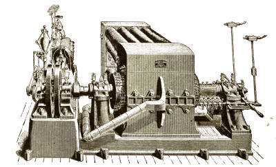
FIRST DIRECT-CONNECTED ELECTRIC GENERATOR UNIT OF LARGE CAPACITY EVER CONSTRUCTED UP TO THE TIME IT WAS MADE BY THOMAS A. EDISON IN JUNE, 1881. CAPACITY, 1200 INCANDESCENT LAMPS OF 16 CANDLE-POWER EACH
FIRST DIRECT-CONNECTED ELECTRIC GENERATOR UNIT OF LARGE CAPACITY EVER BUILT UP TO THE TIME IT WAS MADE BY THOMAS A. EDISON IN JUNE, 1881. CAPACITY, 1200 INCANDESCENT LIGHT BULBS OF 16 CANDLEPOWER EACH
A-B-C
OF
POWER
BY
WILLIAM H. MEADOWCROFT
BY
WILLIAM H. MEADOWCROFT
HARPER & BROTHERS PUBLISHERS
Harper & Brothers Publishers
NEW YORK & LONDON
NEW YORK & LONDON
A-B-C of Electricity
Basics of Electricity
COPYRIGHT, 1888, 1909, BY WILLIAM H. MEADOWCROFT
COPYRIGHT, 1888, 1909, BY WILLIAM H. MEADOWCROFT
COPYRIGHT, 1915, BY HARPER & BROTHERS
PRINTED IN THE UNITED STATES OF AMERICA
PUBLISHED MAY, 1915
COPYRIGHT, 1915, BY HARPER & BROTHERS
PRINTED IN THE UNITED STATES OF AMERICA
PUBLISHED MAY, 1915
From the Laboratory of Thomas A. Edison
From the Lab of Thomas A. Edison
Orange, N. J.
Orange, NJ
Mr. W. H. Meadowcroft,
Mr. W. H. Meadowcroft,
New York City.
NYC.
DEAR SIR:
Hello, Sir:
I have read the MS. of your "A-B-C of Electricity," and find that the statements you have made therein are correct. Your treatment of the subject, and arrangement of the matter, have impressed me favorably.
I have read the manuscript of your "A-B-C of Electricity," and I find that the statements you've made are accurate. Your approach to the topic and the way you've organized the material have left a positive impression on me.
Yours truly,
Sincerely,
THOS. A. EDISON
Thomas A. Edison
CONTENTS
| CHAP. | PAGE | ||
| Intro to New Edition | viii | ||
| Introduction | x | ||
| I. | 1 | ||
| II. | Definitions | 3 | |
| III. | Magnetism | 16 | |
| IV. | The Telegraph | 23 | |
| V. | Wireless Communication | 33 | |
| VI. | The Phone | 40 | |
| VII. | Electric Light | 54 | |
| VIII. | Electricity | 87 | |
| IX. | Batteries | 95 | |
| X. | Conclusion | 127 |
INTRODUCTION TO NEW EDITION
The favor with which this book has been received has brought about the preparation of this new edition. The present volume has been enlarged by the addition of certain new material and it has been entirely reset. Some new illustrations have been made, and in its new dress the book, it is hoped, will be found to afford an even larger measure of usefulness. The principles of the science remain the same, but the author is glad of the opportunity to note certain developments in their application.
The positive response to this book has led to the creation of this new edition. This volume has been expanded with some new material and has been completely reset. New illustrations have been added, and with its fresh look, the book is hoped to provide even more usefulness. The core principles of the science remain unchanged, but the author is pleased to highlight certain developments in their application.
W. H. M.
W.H.M.
Edison Laboratory, April, 1915.
Edison Lab, April 1915.
PREFACE
While there is no lack of most excellent text-books for the study of those branches of Electricity which are above the elementary stage, there is a decided need of text-books which shall explain, in simple language, to young people of, say, fourteen years and upward, a general outline of the science, as well as the ground-work of those electrical inventions which are to-day of such vast commercial importance.
While there are plenty of great textbooks for studying advanced topics in Electricity, there is a clear need for textbooks that explain, in simple terms, the general concepts of the science to young people around fourteen and older, as well as the basics of the electrical inventions that are now so crucial for business.
There is also a need for such a book among a large part of the adult population, for the reason that there have been great and radical changes in this science since the time they completed their studies, and they have not the time to follow up the subject in the advanced books.
There is also a need for such a book among a large portion of the adult population because there have been significant and radical changes in this field since they finished their studies, and they don't have the time to keep up with the subject in advanced texts.
As instances of those changes just spoken of, the electric light, telephone, and storage batteries may be mentioned, which have been developed during the last ten or twelve years, with the result of adding very many[xi] features that were entirely new to electricians.
As examples of the changes just mentioned, we can look at the electric light, telephone, and storage batteries, which have been developed in the last ten to twelve years, adding a lot of features that were completely new to electricians.
With these ideas in view I have prepared this little volume. It is not intended, in the slightest degree, to be put forward as a scientific work, but it will probably give to many the information they desire without requiring too great a research into books which treat more extensively and deeply of this subject.
With these thoughts in mind, I have put together this small book. It’s not meant to be presented as a scientific work, but it will likely provide many readers with the information they want without needing to dive too deeply into books that cover this topic in more detail.
W. H. M.
W.H.M.
A-B-C OF ELECTRICITY
A-B-C of Electricity
A-B-C OF ELECTRICITY
A-B-C of Electricity
I
We now obtain so many of our comforts and conveniences by the use of electricity that all young people ought to learn something of this wonderful force, in order to understand some of the principles which are brought into practice.
We now get so many of our comforts and conveniences from electricity that all young people should learn something about this amazing power to understand some of the principles behind it.
You all know that we have the telegraph, the telephone, the electric light, electric motors on street-cars, electric bells, etc., besides many other conveniences which the use of electricity gives us.
You all know that we have the telegraph, the telephone, electric lights, electric motors on streetcars, electric bells, and many other conveniences that electricity provides us.
Every one knows that, by the laws of multiplication, twice two makes four, and that twice two can never make anything but four. Well, these useful inventions have been made by applying the laws of electricity in certain ways, just as well known, so as to enable us to send in a few moments a message to our[2] absent friends at any distance, to speak with them at a great distance, to light our houses and streets with electric light, and to do many other useful things with quickness and ease.
Everyone knows that, according to the rules of multiplication, two times two equals four, and that two times two can only equal four. Well, these helpful inventions have been created by applying the laws of electricity in certain ways that are just as well known, allowing us to send a message to our[2] absent friends in just a few moments, to talk to them from far away, to light our homes and streets with electric light, and to do many other useful things quickly and easily.
But you must remember that we do not know what electricity itself really is. We only know how to produce it by certain methods, and we also know what we can do with it when we have obtained it.
But you have to remember that we don't actually know what electricity really is. We only know how to generate it through certain methods, and we also know what we can do with it once we have it.
In this little book we will try to explain the various ways by which electricity is obtained, and how it is applied to produce the useful results that we see around us.
In this short book, we will explain the different ways electricity is generated and how it is used to create the useful things we see around us.
We will try and make this explanation such that it will encourage many of you to study this very important and interesting subject more deeply.
We will aim to make this explanation engaging enough to inspire many of you to explore this important and fascinating subject more thoroughly.
In the advanced books on electricity there are many technical terms which are somewhat difficult to understand, but in this book it will only be necessary to use a few of the more simple ones, which it will be well for you to learn and understand before going further.
In the advanced books on electricity, there are many technical terms that can be a bit hard to grasp, but in this book, we'll only need to use a few of the simpler ones. It's important for you to learn and understand these before moving on.
II
DEFINITIONS
DEFINITIONS
The three measurements most frequently used in electricity are
The three measurements most commonly used in electricity are
The Volt,
The Ampère,
The Ohm.
The Volt, The Amp, The Ohm.
We will explain these in their order.
We will explain these in order.
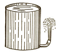
Fig. 1
Fig. 1
The Volt.—This term may be better understood by making a comparison with something you all know of. Suppose we have a tank containing one hundred gallons of water, and we want to discharge it through a half-inch pipe at the bottom of the tank. Suppose, further, that we wanted to make the water spout upward,[4] and for this purpose the pipe was bent upward as in Fig. 1.
The Volt.—You might understand this term better if we compare it to something you’re familiar with. Imagine a tank holding one hundred gallons of water, and we want to release it through a half-inch pipe at the bottom of the tank. Let’s also say we want the water to shoot up, and so the pipe is curved upward as shown in Fig. 1.[4]
If you opened the tap the water would spout out and upward as in Fig. 1.
If you turned on the tap, the water would shoot out and up like in Fig. 1.
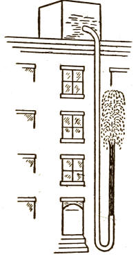
Fig. 2
Fig. 2
The cause of its spouting upward would be the weight or pressure of the water in the tank. This pressure is reckoned as so many pounds to the square inch of water.
The reason it shoots up is due to the weight or pressure of the water in the tank. This pressure is measured in so many pounds per square inch of water.
Now, if the tank were placed on the roof of the house and the pipe brought to the ground as shown in Fig. 2, the water would spout up very much higher, because there would be many more pounds of pressure on account of the height of the pipe.
Now, if the tank is put on the roof of the house and the pipe runs down to the ground as shown in Fig. 2, the water would shoot up much higher because there would be many more pounds of pressure due to the height of the pipe.
So, you see, the force or pressure of water is measured in pounds, and, therefore, a pound is the unit of pressure, or force, of water. Now, in electricity the unit of pressure, or force, is called a volt.
So, you see, the force or pressure of water is measured in pounds, so a pound is the unit of pressure or force of water. Now, in electricity, the unit of pressure or force is called a volt.
This word "volt" does not mean any[5] weight, as the word "pound" weight does. You all know that if you have a pound of water you must have something to hold it, because it has weight, and, consequently, occupies some space. But electricity itself has no weight and therefore cannot occupy any space.
This word "volt" doesn't refer to any[5] weight, unlike the word "pound." You all know that if you have a pound of water, you need something to contain it, because it has weight and, therefore, takes up some space. But electricity itself has no weight and, as a result, can't occupy any space.
When we desire to carry water into a house or other building we do so by means of hollow pipes, which are usually made of iron. This is the way that water is brought into houses in cities and towns, so that it may be drawn and used in any part of a dwelling. Now, the principal supply usually comes from a reservoir which is placed up on high ground so as to give the necessary pounds of pressure to force the water up to the upper part of the houses. If some arrangement of this kind were not made we could get no water in our bedrooms, because, as you know, water will not rise above its own level unless by force.
When we want to bring water into a house or another building, we do it using hollow pipes, which are usually made of iron. This is how water is supplied to homes in cities and towns, allowing it to be accessed and used anywhere in the house. The main supply typically comes from a reservoir located on high ground to provide the necessary pressure to push water up to the upper floors of the buildings. Without this kind of setup, we wouldn’t be able to get water in our bedrooms since, as you know, water won't rise above its own level unless it's pushed.
The water cannot escape as long as there are no holes or leaks in the iron pipes, but if there should be the slightest crevice in them the water will run out.
The water can't escape as long as there are no holes or leaks in the iron pipes, but if there's even the smallest crack in them, the water will leak out.
In electricity we find similar effects.
In electricity, we see similar effects.
The electricity is carried into houses by means of wires which are covered, or insulated,[6] with various substances, such, for instance, as rubber. Just as the iron of the pipes prevents the water from escaping, the insulation of the wire prevents the escape of the electricity.
The electricity is brought into homes through wires that are covered, or insulated,[6] with different materials, like rubber. Just as the metal of the pipes stops the water from leaking, the wire's insulation keeps the electricity from escaping.
Now, if we were to cause the pounds of pressure of water, in pipes of ordinary thickness, to be very greatly increased, the pipes could not stand the strain and would burst and the water escape. So it is with electricity. If there were too many volts of pressure the insulation would not be sufficient to hold it and the electricity would escape through the covering, or insulation, of the wire.
Now, if we were to significantly increase the pressure of water in standard pipes, those pipes wouldn't be able to handle the strain and would break, causing the water to escape. The same is true for electricity. If there were too many volts of pressure, the insulation wouldn't be strong enough to contain it, and the electricity would leak out through the wire's insulation.
It is a simple and easy matter to stop the flow of water from an ordinary faucet by placing your finger over the opening. As the water cannot then flow, your finger is what we will call a non-conductor and the water will be retained in the pipe.
It’s easy to stop the water from a regular faucet by putting your finger over the opening. Since the water can’t flow when you do that, your finger acts as a non-conductor, and the water stays in the pipe.
We have just the same effects in electricity. If we place some substance which is practically a non-conductor, or insulator, such as rubber, around an electric wire, or in the path of an electric current, the electricity, acted upon by the volts of pressure, cannot escape, because the insulation keeps it from doing so, just as the iron of the pipe keeps the[7] water from escaping. Thus, you see, the volt does not itself represent electricity, but only the pressure which forces it through the wire.
We see the same effects in electricity. When we put a material that’s basically a non-conductor, like rubber, around an electric wire or in the path of an electric current, the electricity is prevented from escaping because the insulation keeps it contained, just like the iron pipe keeps the[7] water from leaking out. So, you see, the volt doesn’t represent electricity itself but rather the pressure that pushes it through the wire.
There are other words and expressions in electricity which are sometimes used in connection with the word "volt." These words are "pressure" and "intensity." We might say, for instance, that a certain dynamo machine had an electromotive force of 110 volts; or that the intensity of a cell of a battery was 2 volts, etc.
There are other terms and phrases in electricity that are sometimes used alongside the word "volt." These terms are "pressure" and "intensity." For example, we might say that a particular dynamo machine has an electromotive force of 110 volts, or that the intensity of a battery cell is 2 volts, etc.
We might mention, as another analogy, the pressure of steam in a boiler, which is measured or calculated in pounds, just as the pressure of water is measured. So, we might say that 100 pounds steam pressure used through the medium of a steam-engine to drive a dynamo could thus be changed to electricity at 100 volts pressure.
We could also use the example of steam pressure in a boiler, which is measured in pounds, similar to how we measure water pressure. So, we could say that 100 pounds of steam pressure used by a steam engine to power a generator could be converted into electricity at 100 volts.
The Ampère.—Now, in comparing the pounds pressure of water with the volts of pressure of electricity we used as an illustration a tank of water containing 100 gallons, and we saw that this water had a downward force or pressure in pounds. Let us now see what this pressure was acting upon.
The Ampère.—Now, when we compare the pressure of water in pounds to the voltage of electricity, we used the example of a tank holding 100 gallons of water, and we noted that this water exerts downward force or pressure in pounds. Let’s now examine what this pressure was acting on.
It was forcing the quantity of water to spout upward through the end of the pipe.[8] Now, as the quantity of water was 100 gallons, it could not all be forced at once out of the end of the pipe. The pounds pressure of water acting on the 100 gallons would force it out at a certain rate, which, let us say, would be one gallon per minute.
It was trying to push the amount of water up through the end of the pipe.[8] Since there were 100 gallons of water, it couldn't all be pushed out at once from the end of the pipe. The pressure from the water acting on the 100 gallons would push it out at a certain rate, which we'll say is one gallon per minute.
This would be the rate of the flow of water out of the tank.
This would be the rate of water flow out of the tank.
Thus, you see, we find a second measurement to be considered in discharging the water-tank. The first was the force, or pounds of pressure, and the second the rate at which the quantity of water was being discharged per minute by that pressure.
So, as you can see, we need to look at a second measurement when emptying the water tank. The first was the force, or pounds of pressure, and the second is the rate at which the water is being discharged each minute due to that pressure.
This second measurement teaches us that a certain quantity will pass out of the pipe in a certain time if the pressure is steady, such quantity depending, of course, on the size or friction resistance of the pipe.
This second measurement shows us that a certain quantity will flow out of the pipe in a certain time if the pressure remains consistent, and this quantity, of course, depends on the size or friction resistance of the pipe.
In electricity the volts of pressure act so as to force the quantity of current to flow through the wires at a certain rate per second, and the rate at which it flows is measured in ampères. For instance, let us suppose that an electric lamp required a pressure of 100 volts and a current of one ampère to light it up, we should have to supply a current of electricity flowing at the rate of one ampère, acted upon by an electromotive force of 100 volts.
In electricity, the voltage acts to push the current to flow through the wires at a specific rate per second, and this flow rate is measured in amperes. For example, if an electric lamp needs a voltage of 100 volts and a current of one ampere to turn on, we would need to provide a current of electricity flowing at one ampere, driven by an electromotive force of 100 volts.
You will see, therefore, that while the volt does not represent any electricity, but only its pressure, the ampère represents the rate of flow of the current itself.
You will see, therefore, that while the volt doesn't represent any electricity, but only its pressure, the ampère represents the rate of flow of the current itself.
You should remember that there are several words sometimes used in connection with the word "ampère"—for instance, we might say that a lamp required a "current" of one ampère or that a dynamo would give a "quantity" of 20 ampères.
You should remember that there are several words often used with the word "ampère"—for example, we might say that a lamp needs a "current" of one ampère or that a dynamo would provide a "quantity" of 20 ampères.
The Ohm.—You have learned that the pressure would discharge the quantity of water at a certain rate through the pipe. Now, suppose we were to fix two discharge-pipes to the tank, the water would run away very much quicker, would it not? If we try to find a reason for this, we shall see that a pipe can only, at a given pressure, admit so much water through it at a time.
The Ohm.—You’ve learned that the pressure would release the quantity of water at a certain rate through the pipe. Now, imagine we attach two discharge pipes to the tank; the water would flow out much faster, right? If we look for an explanation, we’ll see that a pipe can only allow a certain amount of water through it at a time, given a specific pressure.
Therefore, you see, this pipe would present a certain amount of resistance to the passage of the total quantity of water, and would only allow a limited quantity at once to go through. But, if we were to attach two or more pipes to the tank, or one large pipe, we should make it easier for the water to flow, and, therefore, the total amount of resistance to the passage of the water would be very much less, and the tank would quickly be emptied.
Therefore, you see, this pipe would create a certain amount of resistance to the flow of water, allowing only a limited amount to pass through at a time. However, if we attached two or more pipes to the tank, or used one large pipe, it would make it easier for the water to flow. As a result, the total resistance to the water's flow would be significantly reduced, and the tank would be emptied quickly.
Now, as you already know, water has substance and weight and therefore occupies some space, but electricity has neither substance nor weight, and therefore cannot occupy any space; consequently, to carry electricity from one place to another we do not need to use a pipe, which is hollow, but we use a solid wire.
Now, as you already know, water has mass and weight, so it takes up space, but electricity has neither mass nor weight and therefore doesn’t occupy any space. Because of this, to transport electricity from one place to another, we don’t use a hollow pipe; instead, we use a solid wire.
These solid wires have a certain amount of resistance to the passage of the electricity, just as the water-pipe has to the water, and (as it is in the case of the water) the effect of the resistance to the passage of electricity is greater if you pass a larger quantity through than a smaller quantity.
These solid wires have a specific level of resistance to the flow of electricity, similar to how a water pipe resists water flow. Just like with water, the resistance to the flow of electricity becomes more significant when you try to push through a larger amount compared to a smaller amount.
If you wanted to carry a quantity of electricity to a certain distance, and for that purpose used a wire, there would be a certain amount of resistance in that wire to the passage of the current through it; but if you used two or more wires of the same size, or one large wire, the resistance would be very much less and the current would flow more easily.
If you wanted to transport electricity over a distance using a wire, there would be some resistance in that wire to the flow of current. However, if you used two or more wires of the same size, or one larger wire, the resistance would be much lower, and the current would flow more easily.
Suppose that, instead of emptying the water-tank from the roof through the pipe, we had just turned the tank over and let the water all pour out at once down to the ground. That would dispose of the water very quickly and by a short way, would it[11] not? That is very easy to be seen, because there would be no resistance to its passage to the ground.
Suppose that, instead of draining the water tank from the roof through the pipe, we just flipped the tank upside down and let all the water pour out at once onto the ground. That would get rid of the water really quickly and easily, right[11]? It’s pretty obvious, because there would be no resistance to its flow to the ground.
Well, suppose we had an electric battery giving a certain quantity of current, say five ampères, and we should take a large wire that would offer no resistance to that quantity and put it from one side of the battery to the other, a large current would flow at once and tend to exhaust the battery. This is called a short circuit because there is little or no resistance, and it provides the current with an easy path to escape. Remember this, that electricity always takes the easiest path. It will take as many paths as are offered, but the largest quantity will always take the easiest.
Well, let's say we have an electric battery providing a specific amount of current, like five amps, and we connect a thick wire that offers no resistance from one terminal of the battery to the other. A strong current would flow immediately and quickly drain the battery. This is called a short circuit because there’s very little or no resistance, giving the current an easy way to escape. Keep this in mind: electricity always takes the easiest route. It will follow as many paths as are available, but the largest current will always choose the easiest one.
As the subject of resistance is one of the most important in electricity, we will give you one more example, because if you can obtain a good understanding of this principle it will help you to comprehend the whole subject more easily in your future studies.
Since resistance is a key concept in electricity, we'll provide you with one more example. If you can get a solid grasp of this principle, it will make it easier for you to understand the entire topic in your future studies.
We started by comparison with a tank holding 100 gallons of water, discharging through a half-inch pipe, and showed you that the pounds of pressure would force the quantity of gallons through the pipe. When the tap was first opened the water would spout up very high, but as the water in the[12] tank became lower the pressure would be less, and, consequently, the water would not spout so high.
We began by comparing it to a tank containing 100 gallons of water, which drains through a half-inch pipe, demonstrating that the pressure in pounds would push a certain amount of gallons through the pipe. When the faucet was first turned on, the water would shoot up really high, but as the water level in the [12] tank dropped, the pressure would decrease, and as a result, the water wouldn’t shoot up as high.
So, if it were desired to keep the water spouting up to the height it started with, we should have to keep the tank full, so as to have the same pounds of pressure all the time. But, if we wanted the water to spout still higher we should have to use other means, such as a force-pump, to obtain a greater pressure.
So, if we wanted to keep the water shooting up to the height it started at, we’d need to keep the tank full to maintain the same pressure all the time. But, if we wanted the water to shoot even higher, we’d need to use other methods, like a force pump, to create greater pressure.
Now, if we should use too many pounds pressure it would force the quantity of water more rapidly through the pipe and would cause the water to become heated because of the resistance of the pipe to the passage of that quantity acted upon by so great a pressure.
Now, if we use too much pressure, it will push the water through the pipe faster and cause the water to heat up due to the pipe's resistance to that large amount of pressure.
This is just the same in electricity, except that the wire itself would become heated, some of the electricity being turned into heat and lost. If a wire were too small for the volts pressure and ampères of current of electricity the resistance of such wire would be overcome, and it would become red-hot and perhaps melt. Electricians are therefore very careful to calculate the resistance of the wires they use before putting them up, especially when they are for electric lighting, in[13] order to make allowances for the ampères of current to flow through them, so that but little of the electricity will be turned into heat and thus rendered useless for their purpose.
This is similar in electricity, except that the wire itself would heat up, with some of the electricity being converted into heat and wasted. If a wire is too small for the voltage and current of electricity, its resistance would be exceeded, causing it to become red-hot and possibly melt. Electricians are very careful to calculate the resistance of the wires they use before installing them, especially for electric lighting, in[13] order to account for the current flowing through them, ensuring that minimal electricity is converted into heat and wasted for their intended purpose.
The unit of resistance is called the ohm (pronounced like "home" without the "h").
The unit of resistance is called the ohm (pronounced like "home" but without the "h").
All wires have a certain resistance per foot, according to the nature of the metal used and the size of the wire—that is to say, the finer the wire the greater number of ohms resistance it has to the foot.
All wires have a specific resistance per foot, depending on the type of metal used and the size of the wire. In other words, the thinner the wire, the more ohms of resistance it has per foot.
Water and electricity flow under very similar conditions—that is to say, each of them must have a channel, or conductor, and each of them requires pressure to force it onward. Water, however, being a tangible substance, requires a hollow conductor; while electricity, being intangible, will flow through a solid conductor. The iron of the water-pipe and the insulation of the electric wire serve the same purpose—namely, that of serving to prevent escape by reason of the pressure exerted.
Water and electricity move under very similar conditions. Both need a channel or conductor, and both require pressure to push them along. However, water, being a physical substance, needs a hollow conductor, whereas electricity, being intangible, can flow through a solid conductor. The iron of the water pipe and the insulation of the electric wire serve the same purpose: to prevent escape due to the pressure applied.
There is another term which should be mentioned in connection with resistance, as they are closely related, and that is opposition. There is no general electrical term of this name, but, as it will be most easily understood[14] from the meaning of the word itself, we have used it.
There’s another term that should be noted in relation to resistance, as they are closely linked, and that is opposition. There isn’t a standard electrical term for this, but since it can be most easily understood[14] from the meaning of the word itself, we have used it.
Let us give an example of what opposition would mean if applied to water. Probably every one knows that a water-wheel is a wheel having large blades, or "paddles," around its circumference.
Let’s give an example of what opposition would mean if applied to water. Probably everyone knows that a water wheel is a wheel with large blades, or "paddles," around its edge.
When the water, in trying to force its passage, rushes against one of these paddles it meets with its opposition, but overcomes it by pushing the paddle away. This brings around more opposition in the shape of another paddle, which the water also pushes away. And so this goes on, the water overcoming this opposition and turning the wheel around, by which means we can get water to do useful work for us.
When the water tries to push through, it hits one of the paddles and faces resistance, but it pushes the paddle away. This creates more resistance from another paddle, which the water also pushes aside. This process continues, with the water overcoming resistance and turning the wheel, allowing us to harness the water to do useful work for us.
You must remember, however, that it is only by putting opposition in the path of a pressure and quantity of water that we can get this work.
You need to remember, though, that we can only achieve this work by placing resistance in the way of a flow and volume of water.
The same principle holds good in electricity. We make electricity in different ways, and in order to obtain useful work we put in its path the instruments, lamps, or machines which offer the proper amount of resistance, or opposition, to its passage, and thus obtain from this wonderful agent the work we desire to have done.
The same principle applies to electricity. We generate electricity in various ways, and to get useful work from it, we place instruments, lamps, or machines in its path that provide the right level of resistance or opposition to its flow. This allows us to harness this amazing force to accomplish the work we want done.
You have learned that three important measurements in electricity are as follows:
You’ve learned that three key measurements in electricity are as follows:
The volt is the practical unit of measurement of pressure;
The volt is the actual unit used to measure pressure;
The ampère is the practical unit of measurement of the rate of flow; and
The ampère is the practical unit of measurement for the rate of flow; and
The ohm is the practical unit of measurement of resistance.
The ohm is the practical unit for measuring resistance.
III
MAGNETISM
MAGNETISM
Now we will try to explain to you something about magnets and magnetism. There are very few boys who have not seen and played with the ordinary magnets, shaped like a horseshoe, which are sold in all toy-stores as well as by those who sell electrical goods.
Now we’re going to explain a bit about magnets and magnetism. Most boys have seen and played with regular magnets shaped like a horseshoe, which you can find in toy stores as well as in stores that sell electrical goods.
Well, you know that these magnets will attract and hold fast anything that is made of iron or steel, but they have no effect on brass, copper, zinc, gold, or silver, yet there is nothing that you can see which should cause any such effect. You will notice, then, that magnetism is like electricity; we cannot see it, but we can tell that it exists, because it produces certain effects. And here is another curious thing—magnetism produces electricity, and electricity produces magnetism. This seems to be a very convenient sort of a family affair, and it is owing to this close relation[17] that we are able to obtain so many wonderful things by the use of electricity.
Well, you know that these magnets will attract and hold onto anything made of iron or steel, but they don't affect brass, copper, zinc, gold, or silver, even though you can't see anything that should cause that effect. You'll notice that magnetism is like electricity; we can't see it, but we know it exists because it produces certain effects. And here's another interesting point—magnetism creates electricity, and electricity creates magnetism. This seems like a pretty convenient family connection, and it’s because of this close relationship[17] that we can achieve so many amazing things using electricity.
We shall now show you how electricity produces magnetism, and, when we come to the subject of electric lighting we will explain how magnetism produces electricity.
We will now show you how electricity creates magnetism, and when we get to the topic of electric lighting, we will explain how magnetism generates electricity.
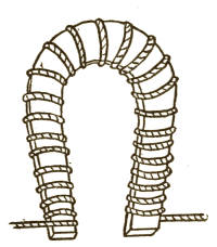
Fig. 3
Fig. 3
The easiest way to show how electricity makes magnetism is to find out how magnets are made. Suppose we wanted to make a horseshoe magnet, just mentioned above; we would take a piece of steel and wind around it some fine copper wire, commencing on one leg of the horseshoe and winding around until we came to the end of the other leg. Then we should have two ends of wire left, as shown in the sketch. (Fig. 3.)
The simplest way to demonstrate how electricity produces magnetism is to explore how magnets are created. Let's say we want to make a horseshoe magnet, like we just talked about; we would take a piece of steel and wrap some fine copper wire around it, starting at one end of the horseshoe and winding it around until we reach the end of the other side. We would then have two ends of wire remaining, as illustrated in the sketch. (Fig. 3.)
We connect these two ends with an electric battery, giving, say, two volts, and then the ampères of current of electricity will travel through the wire, and in doing so has such an influence on the steel that it is converted into a magnet, such as you have played with. The current is "broken"—that is to[18] say, it is shut off several times in making a magnet of this kind, and then the wire is taken away from the battery and is unwound from the steel horseshoe, leaving it free from wire, just as you have seen it. This horseshoe is now a permanent magnet—that is, it will always attract and hold pieces of iron and steel.
We connect these two ends with a battery, providing about two volts, and then the flow of electricity moves through the wire, affecting the steel so that it turns into a magnet, like the ones you’ve played with. The current is "broken"—meaning it's switched off several times while making this type of magnet, and then the wire is removed from the battery and unwound from the steel horseshoe, leaving it free of wire, just like you’ve seen. This horseshoe is now a permanent magnet—in other words, it will always attract and hold pieces of iron and steel.
Now, if you were to do the same thing with a horseshoe made of soft iron instead of steel it would not be a magnet after you stopped the current of electricity from going through the wires, although the piece of iron would be a stronger magnet while the electricity was going through the wire around it.
Now, if you did the same thing with a horseshoe made of soft iron instead of steel, it wouldn't stay a magnet after you stopped the electric current from flowing through the wires. However, the piece of iron would be a stronger magnet while the electricity was still passing through the wire around it.
The steel magnet is called a permanent magnet, and its ends, or "poles," are named North and South. There is usually a loose piece of steel or iron, called an "armature," put across the ends, which has the peculiar property of keeping the magnetism from becoming weaker, and thereby retaining the strength of the magnet. The strongest part of the magnet is at the poles, while, at the point marked + (which is called the neutral point) there is scarcely any magnetism.
The steel magnet is known as a permanent magnet, and its ends, or "poles," are referred to as North and South. Typically, there is a loose piece of steel or iron, called an "armature," placed across the ends, which has the unique ability to prevent the magnetism from weakening, thus maintaining the magnet's strength. The strongest part of the magnet is at the poles, while at the point marked + (known as the neutral point), there is hardly any magnetism.
It will be well to remember the object of the armature as we shall meet it again in describing dynamo machines.
It’s important to keep in mind the purpose of the armature, as we will encounter it again when discussing dynamo machines.
The magnets made of iron are called electromagnets because they exhibit magnetism only when the ampères of current of electricity are flowing around them. They also have two poles, north and south, as have permanent magnets. Electromagnets are used in nearly all electrical instruments, not only because they are stronger than permanent magnets, but because they can be made to act instantly by passing a current of electricity through them at the most convenient moment, as you will see when we explain some of the electrical instruments which are used to produce certain effects. (Fig. 4.)
The magnets made of iron are called electromagnets because they only show magnetism when electricity is flowing around them. They also have two poles, north and south, just like permanent magnets. Electromagnets are used in almost all electrical devices, not only because they are stronger than permanent magnets, but also because they can be activated instantly by sending an electric current through them at the right moment, as you will see when we explain some of the electrical instruments used to create specific effects. (Fig. 4.)
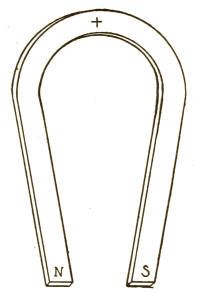
Fig. 4
Fig. 4
Of course there are a great many different shapes in which magnets are made. The simplest is the bar magnet, which is simply a flat or round piece of iron or steel. Suppose you made a magnet of a flat piece of steel and put on top of it a sheet of paper, and then threw on the paper some iron filings, you[20] would see them arrange themselves as is shown in the following sketch. (Fig. 5.)
Of course, there are many different shapes that magnets can take. The simplest is the bar magnet, which is just a flat or round piece of iron or steel. Imagine you create a magnet from a flat piece of steel, place a sheet of paper on it, and then sprinkle some iron filings on the paper; you[20] would see the filings arrange themselves as shown in the following sketch. (Fig. 5.)
The filings would always arrange themselves in this shape, no matter how large or small the magnets were. And, if you were to cut it into two or half a dozen pieces, each piece would have the same effect. This shows you that each piece would itself become a magnet and would have its poles exactly as the large one had.
The filings would always form this shape, regardless of the size of the magnets. And if you were to cut it into two or six pieces, each piece would behave the same way. This shows that each piece would become a magnet in its own right and would have its poles just like the larger one.
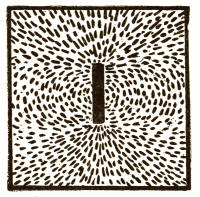
Fig. 5
Fig. 5
Now, we have another curious thing to tell you about magnets. If you present the north pole of a magnet to the south pole of another magnet, they will attract and hold fast to each other, but if you present a south pole to another south pole, or a north pole to a north pole, they will repel each other, and there will be no attraction. You can perform some interesting experiments by reason of this fact. We will give you one of them.
Now, we have something interesting to share about magnets. If you bring the north pole of a magnet close to the south pole of another magnet, they will attract and stick together. But if you bring a south pole to another south pole, or a north pole to another north pole, they will push each other away, and there won’t be any attraction. You can do some fun experiments based on this fact. We'll share one of them with you.
Take, say, a dozen needles and draw them several times in the same direction across the ends of a magnet so that they become magnetized.[21] Now stick each needle half-way through a piece of cork, and put the corks, with the needles sticking through them, into a bowl of water. Then take a bar magnet and bring it gradually toward the middle of the bowl and you will see the corks advance or back away from the magnet. If the ends of the needles sticking up out of the water are south poles and the end of the magnet you present is a north pole, the needles will come to the center; but will go to the side of the bowl if you present the south pole. You can vary this pretty experiment by turning up the other ends of part of the needles.
Take about a dozen needles and run them several times in the same direction across the ends of a magnet to magnetize them.[21] Now stick each needle halfway through a piece of cork, and place the corks, with the needles sticking through them, into a bowl of water. Then take a bar magnet and slowly bring it toward the center of the bowl; you'll see the corks move forward or backward from the magnet. If the ends of the needles sticking up out of the water are south poles and the end of the magnet you bring close is a north pole, the needles will come to the center; but they will move to the side of the bowl if you bring the south pole near. You can change this interesting experiment by flipping up the other ends of some of the needles.
You will remember that when we explained what "resistance" meant, we told you that electricity would always take the easiest path, and while part of it will flow in a small wire, the largest portion will take an easier path if it can get to something larger that is a metallic substance. Electricity will only flow easily through anything that is made of metal. You will also remember that you learned that when electricity took a short cut to get away from its proper path it was called a short circuit.
You’ll remember that when we explained what “resistance” meant, we said that electricity always follows the easiest route, and while some of it will travel through a small wire, the majority will take the easier path if it can reach something larger that’s made of metal. Electricity flows easily through anything made of metal. You’ll also recall that when electricity takes a shortcut away from its intended path, it’s called a short circuit.
All this must be taken into consideration when magnets are being made. In the first[22] place, the wire we wind around steel or iron to make magnets must always be covered with an insulator of electricity. Magnet wire is usually covered with cotton or silk. If it were left bare, each turn of the wire would touch the next turn, and so we should make such an easy path for the electricity that it would all go back to the battery by a short circuit, and then we would get no magnetic effect in the steel or iron. The only way we can get electricity to do useful work for us is to put some resistance or opposition in its way. So you see that if we make it travel through the wire around the iron or steel, there is just enough resistance or opposition in its way to give it work to get through the wire, and this work produces the peculiar effect of making the iron or steel magnetic.
All this needs to be considered when making magnets. First, the wire we wrap around steel or iron to create magnets must always be covered with an electrical insulator. Magnet wire is typically coated with cotton or silk. If it were left exposed, each loop of wire would touch the next one, creating a simple path for the electricity to flow back to the battery via a short circuit, meaning we wouldn't get any magnetic effect in the steel or iron. The only way we can use electricity to do useful work is by adding some resistance or opposition in its path. So, you can see that if we make the electricity travel through the wire around the iron or steel, there’s just enough resistance to provide it with the work it needs to move through the wire, and this work creates the unique effect of magnetizing the iron or steel.
The covering on the wire, as you will remember, is called "insulation."
The material on the wire, as you might recall, is called "insulation."
IV
THE TELEGRAPH
THE TELEGRAPH
Every one knows how very convenient the telegraph is, but there are not many who think how wonderful it is that we can send a message in a few seconds of time to a distant place, even though it were thousands of miles away. And yet, though the present system of telegraphing is a wonderful one, the method of sending a telegram is simple enough. The apparatus that is used in sending a telegram is as follows:
Everyone knows how convenient the telegraph is, but not many consider how amazing it is that we can send a message in just a few seconds to a faraway place, even if it's thousands of miles away. And yet, even though the current telegraph system is impressive, sending a telegram is actually quite straightforward. The equipment used for sending a telegram is as follows:
The Battery.
The Wire.
The Telegraph Key.
The Sounder.
The Battery.
The Wire.
The Telegraph Key.
The Sounder.
The different kinds of electric batteries will be mentioned afterward, so we will not stop now to describe them, but simply state that a battery is used to produce the necessary electricity. As you all know what wire[24] is, there is no necessity of describing it further.
The various types of electric batteries will be discussed later, so we won’t take the time to describe them now, but we will just say that a battery is used to generate the required electricity. Since you all know what wire[24] is, there’s no need to explain it further.
The telegraph key is shown in the sketch below. (Fig. 6.)
The telegraph key is illustrated in the sketch below. (Fig. 6.)
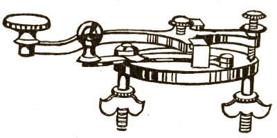
Fig. 6
Fig. 6
This instrument is usually made of brass, except that upon the handle there is the little knob which is of hard rubber. The handle, or lever, moves down when this knob is pressed, and a little spring beneath pushes it up again when let go. You will see a second smaller knob, the use of which we will explain later.
This instrument is usually made of brass, except that the handle has a small knob made of hard rubber. When you press this knob, the handle, or lever, moves down, and a small spring underneath pushes it back up when you release it. You will notice a second, smaller knob, which we will explain later.
The sounder is shown on the following page. (Fig. 7.)
The sounder is displayed on the next page. (Fig. 7.)
The part consisting of the two black pillars is an electromagnet, and across the top of these pillars is a piece of iron called the "armature," which is held up by a spring.
The section made up of the two black pillars is an electromagnet, and there’s a piece of iron on top of these pillars called the "armature," which is supported by a spring.
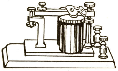
Fig. 7
Fig. 7
Now let us see how the battery and wire are placed in connection with these instruments. You have seen that we usually have two wires for the electricity to travel in, one wire for it to leave the battery, and the other to return on. But you will easily see that if two wires had to be used in telegraphing it would be a very expensive matter, especially when they had to be carried thousands of miles. So, instead of using a second wire, we use the earth to carry back the electricity to the battery, because the earth is a better conductor even than wire. Although a quantity of ground equal in size to the wire would offer thousands of times greater resistance than the wire, yet, owing to the great body[26] of our earth, its total resistance is even less than any telegraph wire used.
Now let’s see how the battery and wire connect to these instruments. You've seen that we usually have two wires for electricity to flow: one wire for it to leave the battery and another to return. But it’s easy to see that using two wires for telegraphing would be very costly, especially when they need to stretch thousands of miles. So, instead of using a second wire, we use the earth to return the electricity to the battery, because the earth is actually a better conductor than wire. While a chunk of ground equal in size to the wire would have thousands of times more resistance than the wire, the massive body of our earth has a total resistance that’s even less than any telegraph wire used.[26]
When two electric wires are run from a battery and connected together through some instrument, this is called a "circuit," because the electricity has a path in which it can travel back to the battery. This would be a "metallic" circuit; but when one wire only is used, and the other side of the battery is connected with the earth, it is called a "ground" or "earth" circuit, because the electricity returns through the earth.
When two electric wires are connected to a battery and linked through a device, this setup is called a "circuit" because the electricity has a path to travel back to the battery. This is known as a "metallic" circuit; but when only one wire is used and the other side of the battery is connected to the ground, it's referred to as a "ground" or "earth" circuit, since the electricity returns through the earth.
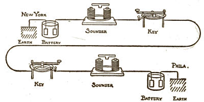
Fig. 8
Fig. 8
If you look at this sketch (Fig. 8) you will see how the telegraph instruments are connected and will then be able to understand how a message can be sent.
If you check out this sketch (Fig. 8), you'll see how the telegraph instruments are connected, and then you'll be able to understand how a message can be sent.
Here we have two sets of telegraph apparatus,[27] one of which, let us say, is in New York and the other in Philadelphia.
Here we have two sets of telegraph equipment,[27] one is, let's say, in New York and the other is in Philadelphia.
You will see that one wire from the battery is connected with the earth, and the other wire with the sounder. Another wire goes from the sounder to one leg of the key so as to make the brass base of the key part of the circuit. The other leg of the key is "insulated" from the brass base by being separated therefrom with some substance which will not carry electricity, such, for instance, as hard rubber.
You’ll notice that one wire from the battery is connected to the ground, while the other wire connects to the sounder. Another wire runs from the sounder to one leg of the key to include the brass base of the key in the circuit. The other leg of the key is "insulated" from the brass base by being separated from it with a material that doesn’t conduct electricity, like hard rubber, for example.
We will suppose that there is already a wire strung up on poles between New York and Philadelphia, and that the key, sounder, and battery in the latter city are connected in the same way as those in New York.
We will assume that there’s already a wire stretched across poles between New York and Philadelphia, and that the key, sounder, and battery in Philadelphia are connected in the same way as those in New York.
Now, to enable us to send a message from one city to the other we must connect the ends of the wires to the instruments in each city; so we connect one end to the insulated leg of the key in New York, and the other end to the insulated leg of the key in Philadelphia.
Now, to let us send a message from one city to another, we need to connect the ends of the wires to the devices in each city; so we connect one end to the insulated leg of the key in New York and the other end to the insulated leg of the key in Philadelphia.
Everything is now completed, and, as soon as we find out what is the use of that part of the key that has a little round, black handle, we shall be ready to start. This is called the "switch."
Everything is now finished, and as soon as we figure out what the part of the key with the little round, black handle is for, we’ll be ready to go. This is called the "switch."
If you will look once more at the picture of the key you will see under the long handle (or lever) a little point which the lever will touch when it is pressed down. Now this little point is part of that insulated leg, and, therefore, this point is also insulated from the base. If a current of electricity were sent along the wire it could not get any farther than this point unless we put in some arrangement to complete the path, or circuit, for it to travel in. We therefore put in the switch.
If you take another look at the picture of the key, you'll notice that under the long handle (or lever) there's a small point that the lever will touch when pushed down. This small point is part of the insulated leg, so it's also insulated from the base. If an electric current were sent through the wire, it couldn't go any further than this point unless we add something to complete the path, or circuit, for it to travel. That's why we include the switch.
One end of the switch (which is made of brass with a rubber handle) is fastened on the base of the key, so that it may be moved to the right or left. The other end, when the switch is moved to the left (or "closed"), touches a piece of brass fastened to the little point we have mentioned, and so makes a free path for the electricity to go through the base of the key and through the wire to the sounder, and from there to the battery, and so back to the earth. This switch must be opened before the sounder near it will respond to its neighboring key.
One end of the switch (which is made of brass with a rubber handle) is attached to the base of the key, allowing it to be moved to the right or left. The other end, when the switch is moved to the left (or "closed"), touches a piece of brass attached to the small point we mentioned, creating a clear path for electricity to flow through the base of the key and the wire to the sounder, then from there to the battery, and back to the ground. This switch needs to be opened before the sounder nearby will react to its neighboring key.
Now we are ready to send a message. Suppose we want to send a telegram from New York to Philadelphia. The operator in New York opens his switch and presses[29] down his key several times. The switch on the Philadelphia key being closed, the electricity goes through to the sounder, and, this being made an electromagnet by the current passing through the wire, the iron armature is attracted by the magnetism and drawn down to the magnet with a snap. It will stay there as long as the New York operator keeps his lever pressed down, but, when he allows it to spring up, there is no current passing through the Philadelphia sounder and there is no magnetism, consequently the armature springs up again with a click.
Now we're ready to send a message. Let's say we want to send a telegram from New York to Philadelphia. The operator in New York flips his switch and presses[29] his key several times. Since the switch on the Philadelphia key is closed, the electricity travels to the sounder. This turns the sounder into an electromagnet because of the current going through the wire, and the iron armature is pulled down to the magnet with a snap. It will stay there as long as the New York operator keeps his lever pressed down, but when he lets it go, the current stops flowing to the Philadelphia sounder, meaning there's no magnetism, and the armature pops back up with a click.
As often as the operator presses down his key lever and lets it spring up again, the same action takes place in the sounder, and it makes that click, click, which you have heard if you have ever seen telegraph instruments in operation.
Every time the operator presses down on his key and lets it spring back up, the same thing happens in the sounder, creating that click, click sound you’ve heard if you’ve ever seen telegraph instruments in use.
Let us continue, however, to send our message. The New York operator, having pressed down his key several times to signal the Philadelphia operator, closes his switch to receive the answer from Philadelphia. The operator in the latter city then opens his switch and presses down his key several times, which makes the New York sounder click, in the same way, to let the operator there know that he is ready to receive the[30] message. He then closes his switch and receives the telegram which the New York operator sends after opening his key.
Let’s keep sending our message. The New York operator, after signaling the Philadelphia operator several times by pressing his key, closes his switch to get the response from Philadelphia. The operator there then opens his switch and presses his key several times, causing the New York sounder to click, letting the operator in New York know he's ready to receive the[30]message. He then closes his switch and receives the telegram that the New York operator sends after opening his key.
Telegraphic messages are sent and received in this way and are read by the sound of the clicks.
Telegraphic messages are sent and received this way and are read by the sound of the clicks.
These sounds may be represented on paper by dots, dashes, and spaces. For instance, if you press down the key and let it spring back quickly, that would represent a dot. If you press down the key and hold it a little longer before letting it spring up again, it would represent a dash. A space would be represented by waiting a little while before pressing down the key again.
These sounds can be shown on paper using dots, dashes, and spaces. For example, if you press the key and let it go back quickly, that represents a dot. If you press the key and hold it down a bit longer before releasing it, that represents a dash. A space is shown by pausing for a moment before pressing the key again.
We show you below the alphabet in these dots, dashes, and spaces, and these are the ones now used in sending all telegraphic messages.
We present the alphabet below using these dots, dashes, and spaces, which are currently used to send all telegraphic messages.
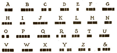
Thus, you see, if you were telegraphing the word "and" you would press down your key and let it return quickly, then press down again and return after a longer pause, which would give the letter A; then slowly and quickly, which would be N; then slowly and twice quickly, which would be D.
Thus, you see, if you were sending the word "and" via telegraph, you would push down your key and let it go back up quickly, then press down again and let it return after a longer pause, which would represent the letter A; then slowly and quickly for N; and finally slowly and twice quickly for D.
Any persevering boy can learn to operate a telegraph instrument by a little study and regular practice; and, as complete learner's sets can be purchased very cheaply, this affords a pleasant and useful recreation for boys.
Any determined boy can learn to use a telegraph instrument with some study and consistent practice; and since complete beginner sets can be bought for a low price, this provides a fun and valuable hobby for boys.
There are many cases where two boys living near each other have a set of telegraph instruments in their homes and run a wire from one house to the other, thus affording many hours of pleasant and profitable amusement.
There are many situations where two boys living close to each other have a set of telegraph instruments in their homes and connect a wire from one house to the other, providing many hours of fun and useful entertainment.
In giving the above explanation of telegraphing we have described only the simple and elementary form. In large telegraph lines, such as those of the Western Union, there are many more additional instruments used, which are very complicated and difficult to understand; such, for instance, as the quadruplex, by which four distinct messages can be sent over the same wire at the same time. We have, therefore, described[32] only the simplest form in order to give the general idea of the working of the telegraph by electromagnetism, which is the principle of all telegraphing.
In this explanation of telegraphy, we only covered the basic and straightforward version. In larger telegraph networks, like those of Western Union, there are many more complex instruments involved, which can be very complicated and hard to grasp; for example, the quadruplex, which allows four separate messages to be sent over the same wire simultaneously. Therefore, we've only described[32] the simplest version to give a general understanding of how the telegraph works through electromagnetism, which is the foundation of all telegraphy.
When you study electricity more deeply you will find this subject and the many different instruments very interesting and wonderful.
When you dive deeper into studying electricity, you'll discover that this topic and the various instruments are really fascinating and amazing.
V
WIRELESS TELEGRAPHY
Wireless Communication
If it has seemed extraordinary to you that only one wire should be necessary for sending a message by the electric telegraph, and that our earth can be used instead of a second wire, how much more wonderful it is to realize that in these days we can exchange telegraphic messages with different points without any connecting wires at all between them, even though the places be many hundred miles apart. Thus, two ships on the ocean, entirely out of sight of each other, may intercommunicate, or may telegraph to or receive despatches from a far-distant shore; indeed, telegraphy without wires has been accomplished across the Atlantic Ocean. In the language of the day, this is called "wireless telegraphy," although it is more correct to think of it as aerial, or space, telegraphy. As you will naturally want to know how this[34] is effected, we will try to explain the main principles in a simple manner.
If it seems amazing to you that only one wire is needed to send a message through the electric telegraph, and that we can use the Earth as a second wire, how much more incredible it is to realize that these days we can send telegraphic messages between different locations without any connecting wires at all, even if they're hundreds of miles apart. For instance, two ships in the ocean, completely out of sight of each other, can communicate, or send and receive messages from a distant shore; in fact, wireless telegraphy has been achieved across the Atlantic Ocean. Nowadays, this is called "wireless telegraphy," but it's more accurate to think of it as aerial or space telegraphy. Since you're likely curious about how this[34] works, we’ll try to explain the main concepts in a straightforward way.
If you drop a stone into a quiet pond, you will see the water form into ring-like waves, or ripples, which travel on and on until they die away in the far distance. These waves are caused, as we have seen, by a disturbance of the body of water.
If you drop a stone into a calm pond, you’ll see the water create ring-like waves or ripples that move outward until they fade away in the distance. These waves are caused, as we’ve observed, by a disruption in the body of water.
Probably you have already learned in school that all known space is said to be filled with a medium called "ether," and that this medium is so exceedingly thin that it penetrates, or permeates, everything, so that it exists in the densest bodies as well as in free space. For the sake of obtaining a clear idea of this theory we may imagine that the ether envelops and permeates every thing in the entire universe. Hence we can easily realize that, although we cannot see or feel the ether, any disturbance of it will set it in wavelike motion.
You probably learned in school that all of known space is filled with a substance called "ether," which is so incredibly thin that it penetrates everything, existing in both dense materials and empty space. To grasp this theory more clearly, we can imagine that ether surrounds and fills everything in the universe. This helps us understand that, even though we can't see or feel the ether, any disturbance in it will create waves.
Modern science accounts for light, radiant heat, and electrical phenomena by reason of wavelike disturbances, vibrations, or pulsations of this ether. Thus, if you should strike a light, the ether would be disturbed, causing waves to form, which, like the waves in the water, would travel in every direction. When these waves reached the eyes of another[35] person within seeing distance, that person's eyes would be so acted upon by the waves that he would see the light which you had made, and would see it instantly, for light waves travel about 186,000 miles per second.
Modern science explains light, radiant heat, and electrical phenomena through wavelike disturbances, vibrations, or pulsations in this ether. So, when you turn on a light, the ether gets disturbed, creating waves that, like water waves, spread out in every direction. When these waves reach the eyes of someone else within view, their eyes are affected by the waves, allowing them to see the light you created, and they see it instantly, as light waves travel at about 186,000 miles per second.
So, if you create an electrical disturbance, the same kind of an effect will be produced; that is to say, waves in the ether will be created, or propagated, and will travel on and on in every direction. Now, if some form of electrical appliance can be made that will be of the right kind to respond to them (as the eye responds to light rays), these electric waves can be made practically useful for transmitting messages through space. This is just what has been done, and we will now give you a brief general description of one kind of apparatus used.
So, if you cause an electrical disturbance, it will create a similar effect; in other words, waves in the ether will be generated and will travel endlessly in all directions. Now, if we can design an electrical device that can respond to these waves (just like the eye responds to light), we can effectively use these electric waves to send messages through space. That's exactly what has been achieved, and we'll now provide a brief overview of one type of device used for this purpose.
For "sending," or "transmitting," as it is usually termed, there is used an induction-coil, having rather large brass balls on the secondary terminals; suitable batteries, a condenser, a Morse telegraph key, and an "aerial," or wire which is carried away up into the air vertically, and is made fast to a pole or special tower. When these are connected properly, the closing of the circuit with the key will cause sparks to jump[36] between the brass balls. This electrical discharge, or oscillation, is carried by the aerial into the upper air and causes intense pulsations in the ether, which set up waves as already mentioned. If the circuit is opened again the disturbance ceases. So, by alternately closing and opening the circuit, the Morse characters can be imitated.
For "sending," or "transmitting," as it’s usually called, an induction coil is used, featuring fairly large brass balls on the secondary terminals; appropriate batteries, a condenser, a Morse telegraph key, and an "aerial," or wire that extends vertically into the air and is secured to a pole or special tower. When these are properly connected, closing the circuit with the key will make sparks jump between the brass balls. This electrical discharge, or oscillation, travels through the aerial into the upper air and creates intense pulsations in the ether, setting up waves as previously mentioned. If the circuit is opened again, the disturbance stops. Thus, by alternately closing and opening the circuit, Morse characters can be mimicked.
But how can these signals be received by the man for whom they are intended, who may be a hundred miles or more away? He has a "receiving" set, consisting of a sensitive relay, batteries, resistance-coils, a Morse register, an aerial, and a special device called a "coherer." This is the important part of the whole set, because it is sensitive to the electrical waves. It consists of a little glass tube about as large around as an ordinary lead-pencil, and perhaps two inches long. In the tube are two metallic plugs, each having a wire attached so that one wire projects from each end of the tube. The plugs are separated inside the tube by a very small space, and in this space are some metal filings. One wire from the coherer is connected to the aerial and the other to the ground. When there are no electrical ether waves to influence them, these filings, being loosely separated, are at rest and offer high[37] resistance; but when the ether is disturbed by electrical vibrations and the waves arrive at the coherer (through the aerial), these filings are drawn together, or cohere. This lowers their resistance and they become a better conductor. Now, the coherer wires are also connected through a battery to the relay, which in turn is connected through another battery to a Morse register. Therefore, when the filings become a conductor, the current flows through them and the circuit to the relay is closed. That attracts an armature which closes the circuit of the Morse register and thus marks the electrical impulse on a strip of paper tape. In the mean time, a restoring device, called a "decoherer," operated also by the relay circuit, has tapped upon the coherer, thus shaking the filings loose again, so that they are ready to cohere again and register another impulse, or character. Thus, by pressing the key at the transmitting end for long or short periods, to represent Morse characters, long and short waves are propagated in the ether and are received and recorded at the receiving end through the coherer and other parts of the receiving set. In this way telegraphic messages are sent and received through space,[38] between points separated by hundreds or thousands of miles.
But how can these signals be picked up by the person they're meant for, who might be over a hundred miles away? They have a "receiving" setup, which includes a sensitive relay, batteries, resistance coils, a Morse register, an aerial, and a special gadget called a "coherer." This is the crucial part of the whole setup because it reacts to the electrical waves. It consists of a small glass tube about the size of a regular pencil and maybe two inches long. Inside the tube are two metal plugs, each with a wire attached so that one wire sticks out from each end of the tube. The plugs are just slightly apart inside the tube, with some metal filings in the gap. One wire from the coherer is connected to the aerial and the other to the ground. When there aren't any electrical ether waves affecting them, these filings, being loosely spaced, remain at rest and provide high resistance; but when the ether is disturbed by electrical vibrations and the waves reach the coherer (via the aerial), these filings are pulled together, or cohere. This reduces their resistance, making them a better conductor. Now, the coherer wires are also linked through a battery to the relay, which is in turn connected through another battery to a Morse register. So, when the filings become conductive, the current flows through them and completes the circuit to the relay. This attracts an armature that closes the circuit of the Morse register, marking the electrical impulse on a strip of paper tape. Meanwhile, a restoring device called a "decoherer," which is also powered by the relay circuit, taps on the coherer, shaking the filings loose again so they're ready to cohere once more and register another impulse, or character. By pressing the key at the sending end for short or long periods to represent Morse characters, long and short waves travel through the ether and are received and recorded at the receiving end via the coherer and other components of the receiving setup. In this way, telegraphic messages are sent and received across space, between locations hundreds or even thousands of miles apart.
We have tried to describe to you the general principles underlying the art of wireless telegraphy as plainly as possible, using for illustration the simplest kind of apparatus employed for the practical sending and receiving of messages. At the present day there are several systems in actual practice, and with the growth of the art there have been many elaborations of apparatus that have come into use. For instance, the coherer is not as much used as formerly. In its place there are employed several kinds of "wave-detectors" as they are now termed, and in many of the systems the electrical pulsations are generated by a dynamo-machine instead of batteries. Then, again, instead of the messages being recorded by a Morse register at the receiving end, the operator receives them by means of a telephone receiver, through which he hears the Morse characters and writes them down in words as he hears them. Generally the aerial, or "antennæ," as it is sometimes named, consists of several wires, sometimes a large number, carried to a considerable height.
We have tried to explain the basic principles behind wireless telegraphy as clearly as possible, using the simplest type of equipment for sending and receiving messages as examples. Nowadays, there are several systems in use, and as the technology has developed, many advanced devices have been introduced. For example, the coherer is not used as much as it used to be. Instead, various types of "wave-detectors" are now employed, and in many systems, electrical pulses are generated by a dynamo machine rather than batteries. Furthermore, instead of recording messages with a Morse register at the receiving end, the operator listens through a telephone receiver, hearing the Morse characters and writing them down as he interprets them. Typically, the aerial, or "antennae," as it's also called, consists of several wires, often a large number, elevated to a significant height.
There are a great many other details which might be written to explain all the complicated[39] apparatus which is used in some of the systems, but it is not intended in this book to offer more than a general explanation of main principles. We must leave it to you to study the details elsewhere if you so desire after you have read these pages.
There are a lot of other details that could be explained to clarify all the complicated[39] equipment used in some systems, but this book aims to provide only a general explanation of the main principles. If you're interested in the specifics, it's up to you to explore them in other sources after you finish reading this.
VI
THE TELEPHONE
THE PHONE
You probably all know that the telephone is an electrical instrument by which one person may talk to another who is at a distance. Not only can we talk to a person who is in a different part of the city, but such great improvements have been made in these instruments that we can talk through the telephone to a person in another city, even though it be hundreds of miles away.
You probably all know that the telephone is an electronic device that allows one person to talk to another who is far away. Not only can we talk to someone in a different part of the city, but thanks to significant advancements in these devices, we can now talk through the telephone to someone in another city, even if it's hundreds of miles away.
The main principle of the telephone is electromagnetism, as in the telegraph, but there are other important points in addition to those we mentioned in describing the latter.
The main principle of the telephone is electromagnetism, just like in the telegraph, but there are other key aspects besides those we discussed in describing the latter.
Let us take first the
Let's start with the
INDUCTION-COIL
You will remember that an electromagnet is made by winding many turns of wire around[41] a piece of iron and sending a current of electricity through this wire.
You’ll remember that an electromagnet is created by wrapping several loops of wire around [41] a piece of iron and passing an electric current through the wire.
Now, suppose this current of electricity was being supplied by two cells of a battery. If you took in your hands the wires coming from these two cells, giving, say, four volts, you could not feel any shock; but if you were to take hold of the ends of the wires on the electromagnet and separate them while this same current was going through, you would get a decided shock.
Now, let's say this electric current is coming from two battery cells. If you grab the wires from these two cells, providing about four volts, you won’t feel any shock; but if you hold the ends of the wires on the electromagnet and disconnect them while the same current is flowing, you would definitely feel a shock.
This separation would "break" the circuit, and the reason you would get a shock is that, while the electricity is acting on the wire, the iron itself is magnetized, and on breaking the circuit reacts upon the wire, producing for a moment more volts of pressure in every turn of it. Thus, you see, this weak pressure of electricity as it travels through the wire can yet produce, through its magnetism, strong momentary effects, but you cannot feel it unless you break the circuit.
This separation would "break" the circuit, and the reason you would get a shock is that, while the electricity is flowing through the wire, the iron itself gets magnetized. When you break the circuit, it reacts on the wire, temporarily generating more volts of pressure in every loop of it. So, you see, this weak flow of electricity traveling through the wire can still create strong momentary effects through its magnetism, but you can't feel it unless you break the circuit.
HOW THE INDUCTION-COIL IS MADE
The object of the induction-coil is to produce high intensity, or pressure, from a comparatively weak pressure and large current of electricity; so, if we add still more wire,[42] the magnet has a larger number of turns to act upon and thus makes a very strong pressure, or large number of volts, but a lesser number of ampères.
The purpose of the induction coil is to generate high voltage from a relatively low voltage and a high current of electricity; so, if we add even more wire, [42] the magnet has more turns to work with, which creates a much stronger voltage, or a higher number of volts, but a lower number of amperes.
Instead of taking one piece of iron, as we would for an ordinary electromagnet, we take a bundle of iron wires in making an induction-coil, as these give a stronger effect. Around this bundle of wires we wrap many turns of insulated copper wire. This is called the primary coil, and the ends of this wire are to be attached to the battery.
Instead of using a single piece of iron like we do for a regular electromagnet, we use a bunch of iron wires to create an induction coil, since this produces a stronger effect. We wrap a lot of insulated copper wire around this bundle of wires. This is called the primary coil, and the ends of this wire connect to the battery.
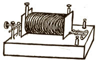
Fig. 9
Fig. 9
On top of, or over, this primary coil we wrap a great many turns of very fine wire, of which, as it is so fine, a great length can be used. This is called the secondary coil, and it is in this coil that the volts, or pressure, of electricity become strongest.
On top of this primary coil, we wrap a large number of turns of very fine wire. Since the wire is so thin, we can use a lot of it. This is called the secondary coil, and it's in this coil that the voltage, or electrical pressure, becomes strongest.
Above we show you a sketch of an induction-coil. (Fig. 9.)
Above we show you a drawing of an induction coil. (Fig. 9.)
At the left-hand side of the cut is a "circuit-breaker," which is simply a piece of iron (armature) on a spring placed opposite[43] the iron core. This armature is made a part of the wire leading to the primary coil. When the current from the battery is sent through the wires, the core becomes magnetized and draws this armature away from a fixed contact point, thus breaking the circuit, but the spring pulls it back, again completing the circuit, and so it keeps going back and forth very rapidly with a br-r-r-ing sound.
On the left side of the cut is a "circuit breaker," which is just a piece of iron (armature) on a spring positioned opposite[43] the iron core. This armature is part of the wire that connects to the primary coil. When the current from the battery flows through the wires, the core gets magnetized and pulls the armature away from a fixed contact point, breaking the circuit. But the spring pulls it back, completing the circuit again, and it keeps moving back and forth very quickly, creating a br-r-r-ing sound.
If you were now to take hold of the ends of the secondary coil you would get a continuous series of quick shocks which would feel like pins and needles running into you.
If you were to grab the ends of the secondary coil now, you would experience a steady stream of quick shocks that would feel like pins and needles shooting into you.
Perhaps most of you have taken hold of the handles of a medical battery and have had shocks therefrom. In so doing, you have simply had the current from the secondary of an induction-coil. The current may be made weaker by sliding a metallic cover over part of the iron core and so shutting off part of the magnetic effect.
Maybe most of you have grabbed the handles of a medical battery and experienced shocks from it. By doing that, you’ve just felt the current from the secondary side of an induction coil. You can reduce the current by sliding a metal cover over part of the iron core, which partially blocks the magnetic effect.
SPARKING COILS
While on this subject we may add that these coils will produce sparks from the two ends of the wire of the secondary coil. These sparks vary in length according to the amount of wire in the coil. Small ones are made[44] which give a spark a quarter of an inch in length, while others are made which will give sparks 10, 12, and 16 inches in length. In the latter, however, there are many miles of wire in the secondary coil.
While we're on this topic, we should mention that these coils will produce sparks from both ends of the wire in the secondary coil. The length of these sparks varies depending on the amount of wire in the coil. Smaller coils generate sparks that are a quarter of an inch long, while larger ones can produce sparks measuring 10, 12, and even 16 inches. However, those longer sparks are produced by coils with many miles of wire in the secondary coil.[44]
The largest induction-coil known is one which was made for an English scientist. There are 341,850 turns, or 280 miles, of wire in the secondary coil. With 30 cells of Grove battery this coil will give a spark 42 inches in length. You may form some idea of the effect of this induction-coil when we state that if we desired to produce the same length of spark direct from batteries, without using an induction-coil, we should require the combined volts of pressure of 60,000 to 100,000 cells of battery.
The largest induction coil known was made for an English scientist. It has 341,850 turns, or 280 miles, of wire in the secondary coil. With 30 Grove battery cells, this coil can produce a spark 42 inches long. To give you an idea of the power of this induction coil, if we wanted to create the same length of spark directly from batteries without using an induction coil, we would need the combined voltage from 60,000 to 100,000 battery cells.
Having explained to you briefly the induction-coil—how it is made and its action—we must ask you to bear these principles in mind, and presently we will tell you how it is used in the telephone.
Having briefly explained the induction coil—how it's made and how it works—we ask you to remember these principles, and soon we will tell you how it is used in the telephone.
The next thing we shall try to explain will be
The next thing we’re going to explain is
THE VIBRATING DIAPHRAGM
Did you ever take the end of a cane in your hand, raise it up over your head, and then bring it down suddenly and sharply, so[45] that it nearly touched the ground, as though you were about to strike something? If not, try it now with a thin walking-cane or with a pine stick about three feet long and one-half inch thick, and you will find that there is a peculiar sound given out. It is not the stick that makes this sound, but it is owing to the fact that you have caused the air to vibrate, or tremble, and thus give out a sound.
Did you ever take the end of a cane in your hand, lift it over your head, and then bring it down suddenly and sharply, so[45] that it almost touches the ground, as if you were about to hit something? If not, try it now with a thin walking cane or a pine stick about three feet long and half an inch thick, and you’ll notice a distinct sound. It's not the stick that creates this sound; it's because you’ve made the air vibrate or tremble, which produces the sound.
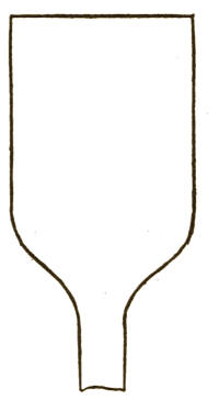
Fig. 10
Fig. 10
If you strike a tuning-fork sharply you will see the ends vibrate and a sound will be given. If you put your fingers on top of a silk hat and speak near it you will feel vibrations of your voice.
If you hit a tuning fork hard, you'll see the ends vibrate and produce sound. If you put your fingers on top of a silk hat and speak near it, you'll feel the vibrations of your voice.
Every time you speak you cause vibrations of the air; and the louder and higher you speak the greater the number of vibrations.
Every time you talk, you create vibrations in the air; and the louder and higher you talk, the more vibrations there are.
Suppose you take a thin piece of wood in your hands (say, for instance, the lid of a cigar-box cut in the shape shown in the picture, Fig. 10) and hold it about two inches from your mouth and then speak. You will feel the wood tremble in your hand. This is because[46] the vibrations of the air cause the wood to vibrate in the same manner. These vibrations are very minute and cannot be seen with the naked eye, but they actually take place, and could be measured with a delicately balanced instrument.
Suppose you take a thin piece of wood in your hands (like the lid of a cigar box shaped like the one shown in the picture, Fig. 10) and hold it about two inches from your mouth and then speak. You will feel the wood shake in your hand. This happens because the vibrations in the air cause the wood to vibrate in the same way. These vibrations are very small and can't be seen with the naked eye, but they do occur and could be measured with a sensitive instrument.
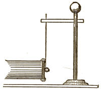
Fig. 11
Fig. 11
Now let us try another experiment in further illustration of this principle. We will take a tube about three inches long and one and one-half or two inches in diameter. This tube may be made of cardboard. Now cut out a piece of thin cardboard which will just fit over one end of the tube. This piece we will call the "diaphragm." Fasten the diaphragm by pasting it with two strips of thin paper to the tube. These strips of paper should be fastened only on the ends, and the middle of the paper allowed to be slack, as shown in the picture, so that the diaphragm may work backward and forward easily. Take a small shot about the size seen in the sketch and tie it to a single thread of fine silk, then let it hang as shown in the[47] sketch (Fig. 11), so that it will only just touch the diaphragm. Now, if you speak into the open end of the tube the diaphragm will vibrate and the shot will be seen to move to and from it according to the strength of the vibrations. If we could by any means make a diaphragm in another tube reproduce these same vibrations, we should hear the same words respoken, if the tube were held to the ear.
Now let’s try another experiment to further illustrate this principle. We'll use a tube that's about three inches long and one and a half to two inches in diameter. This tube can be made of cardboard. Next, cut out a piece of thin cardboard that fits over one end of the tube. We'll call this piece the "diaphragm." Attach the diaphragm by gluing it with two strips of thin paper to the tube. These strips should only be fastened at the ends, leaving the middle of the paper loose, as shown in the picture, so the diaphragm can move back and forth easily. Take a small shot about the size shown in the sketch and tie it to a single thread of fine silk, then let it hang as shown in the [47] sketch (Fig. 11), just touching the diaphragm. Now, if you speak into the open end of the tube, the diaphragm will vibrate and you’ll see the shot move toward and away from it, depending on the strength of the vibrations. If we could somehow create a diaphragm in another tube to reproduce these same vibrations, we would hear the same words repeated if the tube were held to the ear.
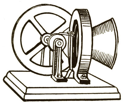
Fig. 12
Fig. 12
While the vibrations caused by the human voice are too minute to be seen, it may seem surprising that they can be made to produce power. This is done by an ingenious mechanism called a Phonomotor, perfected by[48] the great inventor Thomas A. Edison, of whom every one has probably heard. This mechanism, when spoken or sung at (or into) immediately responds by causing a wheel to revolve. No amount of blowing will start the wheel, but it can instantly be set in motion by the vibrations caused by sound.
While the vibrations made by the human voice are too small to see, it might be surprising that they can generate power. This is achieved through a clever device called a Phonomotor, refined by [48] the famous inventor Thomas A. Edison, who is likely known to everyone. This device, when spoken or sung to, immediately reacts by turning a wheel. No amount of blowing will get the wheel moving, but it can be instantly set in motion by the vibrations created by sound.
The Phonomotor (which is shown in the engraving Fig. 12) has a diaphragm and mouthpiece. A spring, which is secured to the bedpiece, rests on a piece of rubber tubing placed against the diaphragm. This spring carries a pawl that acts on a ratchet or roughened wheel on the fly-wheel shaft. A sound made in the mouthpiece creates vibrations in the diaphragm; the vibrations of the diaphragm move the spring and pawl with the same impulses, and as the pawl thus moves back and forth on the ratchet-wheel it is made to revolve.
The Phonomotor (shown in the engraving Fig. 12) has a diaphragm and a mouthpiece. A spring, attached to the base piece, rests on a piece of rubber tubing that is pressed against the diaphragm. This spring carries a pawl that interacts with a ratchet or a textured wheel on the fly-wheel shaft. When a sound is produced in the mouthpiece, it creates vibrations in the diaphragm; these vibrations cause the spring and pawl to move in sync, and as the pawl moves back and forth on the ratchet-wheel, it causes it to rotate.
The instrument, therefore, is of great value for measuring the mechanical force of sound waves, or vibrations, produced by the human voice.
The instrument is very useful for measuring the mechanical force of sound waves or vibrations created by the human voice.
THE TRANSMITTER
That part of the telephone into which we speak is called the transmitter. This is usually[49] a piece of hard rubber having a round mouthpiece cut through it. At the other side of this mouthpiece is placed a diaphragm made of a thin piece of metal, which is held m place by a light spring. Behind this diaphragm, and very close to it, is placed a carbon button. Between this carbon button and the diaphragm is a small piece of platinum, which is placed so as to touch both the button and diaphragm very lightly. This platinum contact piece is connected with one of the wires running to the primary of the induction-coil, and the spring attached to the carbon button is connected with the battery to which the other wire of the primary is connected. This is all shown in the sketch of a transmitter. (Fig. 13.)
The part of the telephone that we speak into is called the transmitter. This is usually made of a piece of hard rubber with a round mouthpiece cut through it. On the other side of this mouthpiece is a diaphragm made of a thin piece of metal, which is held in place by a light spring. Behind this diaphragm, very close to it, is a carbon button. Between this carbon button and the diaphragm is a small piece of platinum, positioned to lightly touch both the button and diaphragm. This platinum contact piece is connected to one of the wires running to the primary of the induction coil, while the spring attached to the carbon button connects to the battery that the other wire of the primary is connected to. This is all illustrated in the sketch of a transmitter. (Fig. 13.)
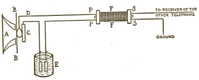
Fig. 13
Fig. 13
A is the mouthpiece; B, the diaphragm; C, the carbon button; D, the wire at the[50] end of which is the platinum contact; E, the battery; and F, the induction-coil; P, P are the wires to the primary, and S, S to the secondary wires.
A is the mouthpiece; B is the diaphragm; C is the carbon button; D is the wire at the[50] end that has the platinum contact; E is the battery; and F is the induction coil; P and P are the wires for the primary, and S and S are for the secondary wires.
We will now say a few words about the receiver, and then describe the manner in which the telephone works.
We will now say a few words about the receiver and then explain how the telephone works.
THE RECEIVER
This is that part of the telephone which is held to the ear, and by which we can hear the words spoken into the transmitter of the telephone at the other end of the line.
This is the part of the phone that you hold against your ear, allowing you to hear the words spoken into the transmitter on the other end of the line.
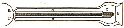
Fig. 14
Fig. 14
The receiver is made of hard rubber, and contains a permanent bar magnet, which is wound with wire so as to make it also an electromagnet when desired. In front of this magnet is placed loosely a diaphragm of thin sheet iron. This diaphragm is placed so as to be within the influence of the magnet,[51] but just so that neither one can touch the other.
The receiver is made of hard rubber and has a permanent bar magnet wrapped in wire, allowing it to function as an electromagnet when needed. In front of this magnet, there's a loosely placed diaphragm made of thin sheet iron. This diaphragm is positioned within the magnet's influence, but they are kept just apart so that they don't touch each other.[51]
Fig. 14 is a sketch of the receiver. A and B are the wires leading to the magnet, C, and D is the diaphragm. E and F are where the wires connect, one from the secondary of the induction-coil in the other telephone, and the other connected with the earth.
Fig. 14 is a sketch of the receiver. A and B are the wires leading to the magnet, C, and D is the diaphragm. E and F are the connection points for the wires, one from the secondary of the induction coil in the other telephone, and the other connected to the ground.
THE CARBON BUTTON
The little carbon button plays an important part in the telephone. You will see from the sketch of the transmitter that the current of electricity will flow through the carbon button to the contact point and through the wire to the primary of the induction-coil.
The small carbon button plays a crucial role in the telephone. As you can see from the sketch of the transmitter, the electric current flows through the carbon button to the contact point and then through the wire to the primary of the induction coil.
Now, carbon has a peculiarity, which is this, that if we press this carbon button, ever so slightly, against the platinum contact, there would be less resistance to the flow of the electricity through the wire to the primary, and the more we press it the less the resistance becomes. The consequence of this would be that more current would go to the primary, and the secondary would become correspondingly stronger. If the carbon button were left untouched, and nothing[52] pressed against it, the flow of current through it would be perfectly even.
Now, carbon has a unique characteristic: if we press this carbon button, even just a little, against the platinum contact, the resistance to the flow of electricity through the wire to the primary decreases. The harder we press it, the less resistance there is. As a result, more current flows to the primary, making the secondary correspondingly stronger. If the carbon button remains untouched and nothing presses against it, the current flow through it will be perfectly steady.
Having examined the inside of the transmitter and receiver, and understanding the effect of pressure on the carbon button, let us now see
Having looked inside the transmitter and receiver, and understanding how pressure affects the carbon button, let's now see
HOW THE TELEPHONE WORKS
When we speak into the mouthpiece of the transmitter, the vibrations of the air cause the diaphragm to vibrate very rapidly, and, of course, every movement of the diaphragm presses more or less against the carbon button, in consequence of which the currents passing through the primary of the induction-coil are constantly increased or diminished and thus produce similar effects, but magnified, in the secondary.
When we talk into the microphone of the transmitter, the air vibrations make the diaphragm vibrate quickly. Every movement of the diaphragm presses more or less against the carbon button, which causes the currents flowing through the primary of the induction coil to be constantly increased or decreased, creating similar but amplified effects in the secondary.
The effect of this is that the magnet in the receiver of the other telephone is receiving a rapidly changing current, which, producing corresponding magnetic changes, makes the magnet alternately weaker or stronger. This influences, by magnetism, the iron diaphragm accordingly, and makes it reproduce the same vibrations that were caused by the speech at the transmitter of the sending telephone. Thus, the same vibrations being[53] reproduced, the original sounds are given out, and we can hear what the person at the sending telephone is saying.
The result of this is that the magnet in the receiver of the other phone is getting a quickly changing current, which causes corresponding magnetic changes, making the magnet alternately weaker or stronger. This affects the iron diaphragm through magnetism, making it reproduce the same vibrations that were caused by the speech at the transmitter of the sending phone. Thus, with the same vibrations being [53] reproduced, the original sounds are emitted, and we can hear what the person on the sending phone is saying.
The action of the telephone illustrates well the wonderfully quick action of the electric current by the reproduction of these sound waves, or air vibrations, for they number many thousands in one minute's speech.
The way the telephone works demonstrates the incredibly fast movement of electric current by reproducing sound waves, or air vibrations, which can number in the thousands during just one minute of speech.
VII
ELECTRIC LIGHT
Electric light
We have now arrived at a very interesting part of the study of electricity, as well as a more difficult part than we have yet told you of, but one which you can easily understand if you read carefully.
We have now reached a really interesting part of the study of electricity, and it's also more challenging than what we've discussed so far. But you can definitely understand it if you read carefully.
You must all have seen electric lights, either in the streets or in some large buildings, for so many electric lights are now used that there are very few people who have not seen them. But perhaps some of you have only seen the large, dazzling lights that are used in the streets, and do not know that there is another kind of electric light which is in a globe about the size and shape of a large pear, and gives about the same light as a good gas-jet.
You all must have seen electric lights, either on the streets or in big buildings, since there are so many electric lights used nowadays that very few people haven't seen them. But maybe some of you have only noticed the bright, flashy lights used outdoors and don't realize that there's another type of electric light that comes in a globe about the size and shape of a large pear, providing light similar to a good gas flame.
These two kinds of electric lights have different names.
These two types of electric lights have different names.
The large, dazzling lights which you see in the streets are called "arc-lights," and the[55] small, pear-shaped lamps, which give a soft, steady light, are called "incandescent lights." We will tell you later why these names are given to them.
The big, bright lights you see in the streets are called "arc lights," and the small, pear-shaped lamps that provide a soft, steady glow are called "incandescent lights." We'll explain later why they have these names.
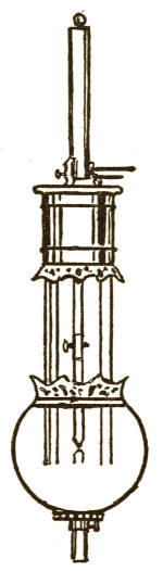
Fig. 15
Fig. 15
The incandescent lights are generally used in houses, stores, theaters, factories, steamboats, and other places where a number of small lights are more pleasant to the eyes. The arc-lights (Fig. 15) are used to light streets and large spaces where a great quantity of light is wanted.
The incandescent lights are usually used in homes, shops, theaters, factories, steamboats, and other places where multiple small lights are easier on the eyes. The arc lights (Fig. 15) are used to illuminate streets and large areas where a lot of light is needed.
It would not be pleasant to have one of these dazzling arc-lamps in your parlor—although it would give a great deal of light—because your eyes would soon become tired. But two or three of the small incandescent lights (Fig. 16) would be very agreeable, because they would give you a nice, soft light to read or work by, and would not tire your eyes. So, you see, these two different kinds of lamps are very useful in their proper places.
It wouldn’t be enjoyable to have one of those bright arc lamps in your living room—while it would provide a lot of light—because your eyes would quickly get tired. However, two or three of the small incandescent lights (Fig. 16) would be quite nice, as they would give off a soft light that’s great for reading or working and wouldn’t strain your eyes. So, you see, these two types of lamps are very useful in the right situations.
Now, if you will read patiently and carefully, we will try and explain how both these lights are made.
Now, if you will read patiently and carefully, we will try to explain how both of these lights are made.
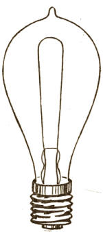
Fig. 16
Fig. 16
You have seen that the telegraph, telephone, electric bells, etc., are worked by batteries. Electric lights, however, require such a large amount of current that it is too expensive to produce them in large quantities by batteries. A small number of lamps could be lighted by batteries, but if we were to attempt to use them to light 500 or 1,000 lamps together, the expense would be so enormous as to make it entirely out of the question.
You’ve noticed that devices like the telegraph, telephone, and electric bells run on batteries. However, electric lights need so much current that it's too costly to power them in large numbers with batteries. A few lamps can be lit with batteries, but trying to light up 500 or 1,000 lamps at once would be so expensive that it’s completely impractical.
There are many millions of incandescent lamps in use in the United States, but you will easily see that there could not be that number used if we had to depend on batteries to light them. You will understand this[57] more thoroughly when you have finished reading this little book.
There are millions of incandescent lamps in use in the United States, but you can easily see that there couldn't be that many if we had to rely on batteries to power them. You'll understand this[57] more thoroughly once you finish reading this short book.
Well, you will ask, if we cannot use batteries, what is used to produce these electric lights?
Well, you might ask, if we can’t use batteries, what’s used to produce these electric lights?
Machines called "dynamo-electric machines," or "generators," which are driven by steam-engines or water-power, are used to produce the electricity which makes these lamps give us light.
Machines called "dynamo-electric machines," or "generators," powered by steam engines or water power, are used to produce the electricity that makes these lamps light up.
You will remember that in the chapter on Magnetism we explained to you how electricity makes magnetism, and now we will explain how, in the dynamo, magnetism makes electricity.
You will remember that in the chapter on Magnetism we explained how electricity creates magnetism, and now we will explain how, in the dynamo, magnetism creates electricity.
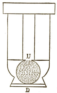
Fig. 17
Fig. 17
It has been found that the influence of a magnet is very strong at its poles, and that this influence is always in the same lines. This influence has been described as "lines of force," which you will see represented in the sketch above by the dotted lines (Fig. 17). Of course, these lines[58] of force are only imaginary and cannot be seen in any magnet, but they are always present. The meaning of this term "lines of force," then, is used to designate the strength of the magnet.
It has been discovered that the pull of a magnet is strongest at its poles, and this pull always follows the same direction. This pull has been referred to as "lines of force," which you can see illustrated in the sketch above by the dotted lines (Fig. 17). Of course, these lines[58] of force are just a concept and can't be seen in any magnet, but they are always there. Therefore, the term "lines of force" is used to indicate the strength of the magnet.
Many years ago the great scientist Faraday made the discovery that, by passing a closed loop of wire through the magnetic lines of force existing between the poles of a magnet, the magnetism produced the peculiar effect of creating a current of electricity in the wire. If the closed loop of wire were passed down, say from U to D, the current flowed in the wire in one direction, and if it were passed upward, from D to U, the current flowed in the other direction. Thus, you see, magnetism produces electricity in the closed loop of wire as it cuts through the magnetic lines of force. Just why or how, nobody knows; we only know that electricity is produced in that way, and to-day we make practical use of this method of producing it by embodying this principle in dynamo-machines, as we will shortly explain.
Many years ago, the great scientist Faraday discovered that when a closed loop of wire is moved through the magnetic field between the poles of a magnet, it creates an electric current in the wire. If the loop is moved downward, from U to D, the current flows in one direction; if it's moved upward, from D to U, the current flows in the opposite direction. So, magnetism generates electricity in the closed loop of wire as it passes through the magnetic field lines. The exact reasons why this happens are still unknown; we just know that electricity is generated this way, and today we use this principle in devices like dynamo machines, which we will explain shortly.
In carrying this discovery into practice in making dynamo-machines we use copper wire. If iron were used, there would be a current of electricity generated, but it would be much less in quantity, because iron wire[59] has much greater resistance to the passage of electricity than the same size of copper wire.
In applying this discovery to the construction of dynamo machines, we use copper wire. If we used iron, a current of electricity would be generated, but it would be significantly less because iron wire[59] has much higher resistance to the flow of electricity compared to the same size of copper wire.
Perhaps you can understand it more thoroughly if we state that when a closed loop of wire is passed up and down between the poles of a strong magnet there is a very perceptible opposition felt to the passage of the wire to and fro.
Maybe you'll get it better if we say that when a closed loop of wire is moved up and down between the poles of a strong magnet, there’s a noticeable resistance to the wire's movement back and forth.
This is due to the influence of the magnetism upon the current produced in the wire as it cuts through the lines of force, and, inasmuch as these lines of force are always present at the poles of a magnet, you will see that, no matter how many times you pass the loop of wire up and down, there will be created in it a current of electricity by its passage through the lines of force.
This is because of the influence of magnetism on the current generated in the wire as it moves through the magnetic field. Since these lines of force are always present at the poles of a magnet, you’ll see that no matter how many times you move the loop of wire up and down, it will create an electric current as it passes through the magnetic field.
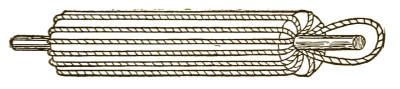
Fig. 18
Fig. 18
Suppose that, instead of using one single loop of copper wire, you wound upon a spool a long piece of wire like that in Fig. 18, and that you turned this spool around rapidly between the poles of the magnet, you would[60] thus be cutting the lines of force by the same wire a great many times, and every time one length of the wire cut through the lines of force some electricity would be generated in it, and this would continue as long as the spool was revolved. But, as each length would only be a part of the one piece of wire, you will easily see that there would be a great deal of electricity generated in the whole piece of wire.
Imagine that instead of using one single loop of copper wire, you wound a long piece of wire like the one in Fig. 18 onto a spool, and you spun this spool quickly between the poles of the magnet. You would[60] be cutting through the lines of force with the same wire multiple times, and every time a segment of the wire passed through the lines of force, some electricity would be generated in it, and this would keep happening as long as the spool was spinning. Since each segment would just be part of the one piece of wire, it’s clear that a lot of electricity would be generated in the entire piece of wire.
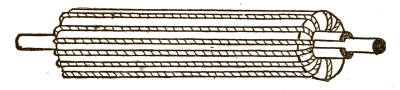
Fig. 19
Fig. 19
All we have to do, then, is to collect this electricity from the two ends of the wire, and use it. If we should attach two wires to the two ends of this wire on the spool, they would be broken off when it turned around, so we must use some other method. We fix on the end of the spool (which is called an "armature") two pieces of copper, so that they will not touch each other (as in Fig. 19), and fasten the ends of the wire to these pieces of copper. This is called a "commutator," and, as you see, is really the ends of the wire on the spool. Now we get two thin,[61] flat pieces of copper and fix them so that they will rest upon the copper bars of the commutator, but will not go round with it. These two flat pieces of copper are called the "brushes," and they will collect from the commutator the electricity which is gathered in the wire around the spool. As the brushes stand still, two wires can be fastened to them, and thus the ampères of current of electricity, acted upon by the volts pressure, can be carried away to be used in the lamps, for you must remember that as long as the spool turns around it gathers more electricity while there is any magnetism for the wire on the spool to pass through. The constant revolving of the spool creates so much electricity that it is driven out from the wire on the spool, through the commutator to the brushes, and there it finds a path to travel away from the pressure of the new electricity which is all the time being made.
All we have to do now is collect this electricity from both ends of the wire and use it. If we attach two wires to the ends of the wire on the spool, they would be broken off when it spins around, so we need a different approach. We attach two pieces of copper to the end of the spool (called an "armature") so that they don’t touch each other (as shown in Fig. 19), and connect the ends of the wire to these pieces of copper. This setup is called a "commutator," and as you can see, it effectively consists of the ends of the wire on the spool. Now we take two thin, flat pieces of copper and position them so that they rest on the copper bars of the commutator, but do not rotate with it. These two flat pieces of copper are known as the "brushes," and they will collect the electricity generated in the wire around the spool from the commutator. Since the brushes stay still, we can attach two wires to them, allowing the amperes of current to be carried away, acted upon by the voltage pressure, to power the lamps. Keep in mind that as long as the spool turns, it continues to generate more electricity while there is magnetism for the wire on the spool to pass through. The constant spinning of the spool produces so much electricity that it is pushed out from the wire on the spool, through the commutator to the brushes, providing a path for the new electricity that is constantly being generated to flow away.
In this way we get a continuous current of electricity in the two wires leading from the commutator, and can use it to light electric lamps or for other useful purposes.
In this way, we generate a steady flow of electricity in the two wires connected to the commutator, which we can use to power electric lamps or for other practical applications.
In explaining this to you, so far, we have used as an illustration of the magnet one of the steel permanent magnets in order to[62] make the explanation more simple, but now that you understand how the electricity is made, we must explain to you something about the magnets that are used in dynamo-machines. We can perhaps make this more clear by giving another example.
In explaining this to you, so far, we have used a steel permanent magnet as an illustration to make things simpler. But now that you understand how electricity is generated, we need to explain something about the magnets used in dynamo machines. We can perhaps clarify this further by providing another example.
Suppose you had a dynamo which was lighting up 100 of the incandescent lamps, each of 200 ohms resistance and each requiring 100 volts pressure. Now each lamp would take just a certain quantity of electricity, say half an ampère; so, the 100 lamps would require one hundred times that quantity. But, if you turned off 50 of these lamps at once, the tendency would be for the pressure to rise above the 100 volts required for the other 50, and they would be apt to burn out quicker. It is plainly to be seen, then, that we must have some means of regulating the magnetism so as to regulate the lines of force for the wire on the armature to cut through. We can do this with an electromagnet, but not with a permanent magnet, because we cannot easily regulate the amount of magnetism which a permanent magnet will give.
Imagine you have a dynamo powering 100 incandescent lamps, each with a resistance of 200 ohms and requiring 100 volts. Each lamp draws a specific amount of electricity, let’s say half an amp; so, the 100 lamps would need a total of one hundred times that amount. However, if you turned off 50 of these lamps at once, the voltage would tend to rise above the 100 volts needed for the remaining 50, potentially causing them to burn out faster. It’s clear that we need a way to regulate the magnetism to control the magnetic lines of force that the wire on the armature cuts through. We can achieve this with an electromagnet, but not with a permanent magnet, because we cannot easily control the amount of magnetism that a permanent magnet produces.
There is another reason why we cannot use permanent magnets in a dynamo, and that is because they cannot be made to give[63] as much magnetism as an electromagnet will give.
There’s another reason we can’t use permanent magnets in a dynamo: they can’t produce[63] as much magnetism as an electromagnet can.
Thus you will see that there are very good reasons for using electromagnets in making dynamo-machines. Let us see now how these electromagnets and dynamos are made, and then examine the methods which are followed to operate and use them.
Thus you will see that there are solid reasons for using electromagnets in the creation of dynamo machines. Now let's explore how these electromagnets and dynamos are made, and then look at the methods used to operate and utilize them.
You must remember, to begin with, that in referring to wire used on magnets and armatures and for carrying the electricity away to the lamps, we always mean wire that is covered or insulated. In electric lighting, insulated wire is always used, except at the points where it is connected with, the dynamo, the lamps, a switch, or any point where we make what is called a "connection."
You need to keep in mind that when we talk about the wire used in magnets and armatures, as well as for carrying electricity to the lights, we're always referring to wire that is covered or insulated. In electric lighting, insulated wire is always used, except at the points where it connects to the dynamo, the lamps, a switch, or any point where we make what's called a "connection."
As the shape of the magnets is different in the dynamos of various inventors, we will take for illustration the one that is nearest the shape of the horseshoe and the shape that is generally used in illustrating the principle of the dynamo. This is the form used by Mr. Edison, whom we have previously mentioned. This form is shown in Fig. 20.
As the shape of the magnets varies in the dynamos invented by different pioneers, we will use the one that closely resembles a horseshoe and is commonly used to explain how a dynamo works. This is the design used by Mr. Edison, whom we mentioned earlier. This design is illustrated in Fig. 20.
Now, although this magnet appears to be in one piece, it really consists of five parts screwed together so as to make, practically,[64] one piece. The names of the parts are as follows: F, F are the "cores"; C the "yoke," which binds them together; and P, P the "pole pieces," where the magnetism is the strongest. These pole pieces are rounded out to receive the armature, which, as you will remember, is the part that turns around.
Now, even though this magnet looks like it's all one piece, it's actually made up of five parts screwed together to practically form[64] a single piece. The parts are named like this: F, F are the "cores"; C is the "yoke," which holds them together; and P, P are the "pole pieces," where the magnetism is strongest. These pole pieces are shaped to fit the armature, which, as you remember, is the part that rotates.
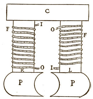
Fig. 20
Fig. 20
The cores, F, F, are first wound with a certain amount of wire, which depends upon the use the dynamo is to be made for. Thus, you will see, there will be on each core two loose ends of the wire that is wound around it—namely, the beginning of the wire and the end where we leave off winding, which on the two cores together will make four ends of wire. We will tell you presently what is done with them.
The cores, F, F, are first wrapped with a specific amount of wire, which depends on how the dynamo will be used. So, as you can see, each core will have two loose ends of the wire that's been wrapped around it—specifically, the start of the wire and the end where we stop wrapping. Together, the two cores will have four ends of wire. We'll explain what to do with them shortly.
After the cores are wound, they are screwed firmly to the yoke and to the pole pieces, so as to make, for all practical purposes, one[65] whole piece pretty nearly the shape of a horseshoe magnet.
After the cores are wound, they are tightly screwed to the yoke and the pole pieces to essentially create one[65] solid unit that is almost in the shape of a horseshoe magnet.
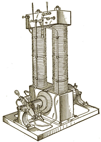
Fig. 21
Fig. 21
Now, to make the dynamo complete, we must put in the armature between the poles, which are rounded off, as you will see, to accommodate it. The armature is held up by two "bearings," which you will see in the sketch of the complete dynamo above. (Fig. 21.)
Now, to complete the dynamo, we need to place the armature between the poles, which are rounded off to fit it. The armature is supported by two "bearings," which you can see in the sketch of the complete dynamo above. (Fig. 21.)
The armature in a practical dynamo-machine consists of a large spool made of thin sheets of iron firmly fastened together and having a steel shaft run through the center, upon which it revolves.
The armature in a practical dynamo machine consists of a large spool made of thin sheets of iron securely fastened together, with a steel shaft running through the center, around which it spins.
This spool, or armature, is wound with a number of strands of copper wire. The commutator, instead of consisting of two bars, is made in many dynamos with as many bars as there are strands of wire, and the ends of these wires are fastened to the bars of the commutator so as to make, practically, one long piece of wire, just as we showed you in explaining how the electricity was produced.
This spool, or armature, is wrapped with several strands of copper wire. Instead of having just two bars, in many dynamos, the commutator has as many bars as there are wire strands. The ends of these wires are connected to the commutator bars to effectively create one long piece of wire, just like we demonstrated when explaining how electricity is generated.
The brushes, resting upon the commutator, carry away the electricity from it into the wires with which they are connected.
The brushes, sitting on the commutator, transfer electricity from it into the wires they're connected to.
Now we have our dynamo all put together and ready to start as soon as we properly connect these four loose ends of wire on the cores.
Now we have our dynamo all assembled and ready to go as soon as we properly connect these four loose ends of wire on the cores.
If you will turn back to Fig. 20 you will see that two of the wires are marked I, and the other two O. The letter I means the inside wire, or where the winding began, and the letter O means the outside wire, or where we left off winding.
If you go back to Fig. 20, you'll see that two of the wires are labeled I, and the other two are labeled O. The letter I stands for the inside wire, where the winding started, and the letter O stands for the outside wire, where we finished winding.
Now, if we fasten together (or "connect") the two ends of wires, I and O, near the top[67] of the magnet, we make the two wires round the cores into one wire, which starts, say, at I near the poles, goes all around one core, crosses over and around the other core down to the other end of the wire to O, near the poles.
Now, if we connect the two ends of the wires, I and O, near the top[67] of the magnet, we create a single wire that wraps around both cores. It starts at I near the poles, goes all the way around one core, crosses over, and wraps around the other core down to the other end of the wire at O, also near the poles.
So far we have called the iron a magnet, although it is not a magnet until electricity is put into it; so, when the dynamo is started for the first time, these two ends of wire, I and O, are connected to a battery or other source of current for the purpose of sending electricity through the wire on the cores. When the electricity goes into this wire the iron immediately becomes a magnet, and the lines of force are present at the poles.
So far, we've referred to the iron as a magnet, even though it doesn't actually become a magnet until electricity is applied. When the dynamo is first turned on, the two ends of wire, I and O, are connected to a battery or another power source in order to send electricity through the wire on the cores. As soon as the electricity flows through this wire, the iron instantly turns into a magnet, and the lines of force appear at the poles.
Now, the armature is turned around rapidly by a steam-engine, and, as the wire on the armature cuts the lines of force with great rapidity and so frequently, there is quickly generated a large quantity of electricity, which passes out as fast as it is made through the commutator and the brushes to the lamp. And so long as the armature is revolved and the battery attached, the electricity will be made, or, as it is usually termed, "generated."
Now, the armature spins quickly thanks to a steam engine, and since the wire on the armature cuts through the lines of force rapidly and often, a large amount of electricity is generated almost instantly. This electricity flows out as fast as it's produced through the commutator and the brushes to the lamp. As long as the armature keeps spinning and the battery is connected, the electricity will continue to be generated.
As we stated above, a battery is used the first time the dynamo is run, and now we will explain why it is not needed afterward.
As we mentioned earlier, a battery is used the first time the dynamo is run, and now we will explain why it isn't needed afterward.
Although iron will not become a permanent magnet, like steel, it does not lose all its magnetism after it has been once thoroughly charged. When the dynamo is stopped, after the first trial, and the battery is taken away, you will discover only traces of magnetism about the poles. They will not readily attract even a needle or iron filings; but there is, nevertheless, a very small amount of magnetism left in the iron. Small as this magnetism is, however, it is enough to make very faint and weak lines of force at the poles of the magnet.
Although iron won't become a permanent magnet like steel, it doesn't lose all its magnetism after being fully charged once. When the dynamo stops after the first trial and the battery is removed, you’ll only find traces of magnetism around the poles. They won’t easily attract even a needle or iron filings, but there is still a tiny amount of magnetism left in the iron. Despite how small this magnetism is, it's enough to create very faint and weak lines of force at the poles of the magnet.
After the battery is taken away, the ends of the wire on the cores, which were connected to the battery, are connected, instead, to the wires which carry away the electricity from the brushes to the lamps. Thus, you will see, if any electricity goes from the dynamo to the lamps, part of it must also find its way through the wires which are around the cores.
After the battery is removed, the ends of the wire on the cores that were connected to the battery are now connected to the wires that carry electricity from the brushes to the lamps. So, as you can see, if any electricity flows from the dynamo to the lamps, some of it must also pass through the wires surrounding the cores.
We will now start up the dynamo without having any battery attached and see what happens. The armature turns around and the wires upon it cut through those very faint lines of force which are always at the poles. This, as you know, makes some electricity; very little, to be sure, but it comes out[69] through the brushes to the wires leading to the lamps, and there it finds the wires leading back to the cores. Well, part of this weak current of electricity goes into these wires and travels back round the cores and so makes the magnetism stronger. The consequence of this is that the lines of force become stronger and, as the armature keeps turning around, the electricity naturally becomes stronger, and so there is more of it going through the wires back to the cores and increasing the strength of the magnet all the time, until the dynamo becomes strong enough to generate all the current it was intended to give for the lamps.
We'll now start the dynamo without a battery connected and see what happens. The armature spins, and the wires on it cut through those faint lines of force that are always present at the poles. This, as you know, generates some electricity; very little, of course, but it comes out[69] through the brushes to the wires leading to the lamps, where it connects back to the cores. Part of this weak electric current goes into these wires and travels back around the cores, which increases the magnetism. As a result, the lines of force become stronger, and since the armature keeps spinning, the electricity naturally becomes stronger too, leading to more of it flowing through the wires back to the cores, continuously boosting the strength of the magnet until the dynamo is strong enough to generate all the current it was meant to provide for the lamps.
Of course, you understand that the stronger the magnet becomes, the greater will be the lines of force and the greater the amount of electricity made by the turning of the armature. Now, there is naturally a limit to what can be done with any particular dynamo; so, while the electricity continues to strengthen the magnetism and the magnetism increases the electricity, this cannot go beyond what is called the "saturation" point of the magnet.
Of course, you get that the stronger the magnet gets, the more lines of force there will be and the more electricity will be generated by the spinning of the armature. Now, there’s naturally a limit to what can be achieved with any specific dynamo; so, while the electricity keeps boosting the magnetism and the magnetism increases the electricity, this can’t exceed what’s known as the "saturation" point of the magnet.
Saturation means that the iron is full of magnetism, and will hold that much but no more. You will learn more as to the saturation[70] of magnets when you study electricity more deeply, and we therefore do not intend to enter into that subject in this book. We will only state, however, that the magnets of dynamos are not always charged up to their saturation point.
Saturation means that the iron is fully magnetized and will retain that level of magnetism, but not exceed it. You'll learn more about magnet saturation[70] when you explore electricity in more detail, so we won’t cover that topic in this book. However, we will mention that the magnets in dynamos are not always charged to their saturation point.
THE LAMPS
So far you have learned how the current of electricity is produced, and now we will follow along the wires to find out how it makes the lamps give out both strong lights and the smaller, pleasant ones.
So far, you have learned how electricity is generated, and now we will follow the wires to discover how it causes the lamps to emit both bright lights and softer, pleasant ones.
Suppose we take first the large, dazzling lights we see in the streets, which, as you know, are called
Suppose we first consider the large, bright lights we see in the streets, which, as you know, are called
ARC-LIGHTS
Those who have seen the arc-lamps will readily recognize them from the picture in Fig. 22.
Those who have seen the arc lamps will easily recognize them from the picture in Fig. 22.
You will see that there are two sticks, or "pencils," of carbon. Now you will remember that in the chapter on Magnetism we told you that in order to have electricity do work for us we must put some resistance or opposition in its way. When we get light[71] from an electric lamp it is because we make the electricity do some work in the lamp, and this work is in pushing its way through a resistance or opposition which is in the lamp.
You will see that there are two sticks, or "pencils," of carbon. Now you will remember that in the chapter on Magnetism we mentioned that to make electricity do work for us, we need to introduce some resistance or opposition in its path. When we get light[71] from an electric lamp, it's because we're making the electricity do some work in the lamp, and this work involves pushing through the resistance or opposition present in the lamp.
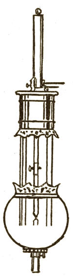
Fig. 22
Fig. 22
When we generate electricity in the dynamo and put two wires for it to travel in, the current goes away from the dynamo through one of the wires and will go back to the dynamo through the other one if it can possibly get a chance to get to this other one. Now, the electricity which is constantly being made fills the wires and acts as a pressure to force the current through the wires back to the dynamo, and, if we put no resistance or opposition in the way, it would have a very easy path to travel in and would do no work at all. The wires leading to an electric lamp should have very little resistance, not sufficient to require any work from the current in passing through.
When we produce electricity in the dynamo and connect two wires for it to flow through, the current moves away from the dynamo through one wire and will return to the dynamo through the other wire if it has the opportunity. The electricity that is continuously generated fills the wires and creates pressure to push the current back to the dynamo. If there is no resistance or obstruction in the way, the current would flow easily without doing any work. The wires leading to an electric lamp should have very low resistance, not enough to require any effort from the current as it passes through.
So, if we bring the two carbons in an arc-lamp together they really form part of the[72] wire, and do not interrupt the current in its travels, but, if we separate the carbons, we make a gap which the current must jump across if it wants to go on. As the volts, or pressure, is so great, the current must jump, and this against the resistance or opposition in an arc-lamp is that which gives the current so much work to do. Indeed, so hard is it for the current to jump across this gap that it breaks off from one carbon a shower of tiny particles as fine as the finest dust, and makes them white hot in passing to the other. This shower of fine carbon dust, together with the ends of the carbons, being white hot, of course makes a light, and this is the dazzling light which you see in the arc-lamp.
So, when we bring the two carbon rods in an arc lamp together, they actually become part of the[72] wire and don’t interrupt the flow of electricity. However, if we separate the carbons, we create a gap that the current has to jump across to continue flowing. Since the voltage, or pressure, is so high, the current has to jump, and this against the resistance or opposition in an arc lamp is what makes the current do so much work. In fact, it’s so difficult for the current to jump across this gap that it breaks off tiny particles from one carbon, as fine as dust, and heats them to white hot as they travel to the other. This cloud of fine carbon dust, along with the hot ends of the carbons, obviously produces light, which is the brilliant glow you see in the arc lamp.
Of course, when the electricity has jumped over from one carbon to the other, it goes through it to the wire, and so passes on to the next lamp, where it has to jump again, and so on until it has gone through the last lamp, then it has an easy path to get back to the dynamo.
Of course, when the electricity moves from one carbon to another, it travels through to the wire, then goes on to the next lamp, where it has to jump again, and so on until it has gone through the last lamp. After that, it has an easy route to return to the dynamo.
Now, we want you to understand more thoroughly how that much resistance or opposition will cause heat, so we will try to give you a simple example.
Now, we want you to understand better how a lot of resistance or opposition creates heat, so we’ll give you a straightforward example.
Most of you know that if you were holding a rope tightly in your hands and some[73] one pulled it through them quickly and suddenly, it would get very hot and your hands would feel as though they were being burned. This is heat caused by your hands resisting or opposing the passage of the rope through them, and if you could hold on tightly enough and the rope was drawn through quickly enough, it would take fire. This fire would, therefore, cause heat and light.
Most of you know that if you were gripping a rope tightly in your hands and someone pulled it through quickly and suddenly, it would get really hot, and your hands would feel like they were burning. This heat is caused by your hands resisting the rope as it passes through, and if you could hold on tight enough and the rope was pulled through quickly enough, it could ignite. This fire would then produce heat and light.
It is just this principle of resistance to the passage of the current which causes the light in an arc-lamp, as we have shown you.
It’s this principle of resisting the flow of current that creates the light in an arc lamp, as we have demonstrated.
INCANDESCENT LAMPS
You have just learned that the light in an arc-lamp is caused by the current forcing off from the carbon sticks tiny particles and heating them up until they give a brilliant light. So, you see, in an arc-light there is a wearing away of carbon by electricity, and therefore these sticks, or pencils, of carbon in time are all burned away. In practice the carbon pencils last about eight or ten hours, and then new ones must be put in.
You’ve just found out that the light in an arc lamp comes from the current pushing off tiny particles from the carbon rods and heating them up until they shine brightly. So, as you can see, in an arc light, the carbon is gradually worn away by the electricity, which means these carbon rods, or pencils, eventually get completely used up. Typically, the carbon pencils last about eight to ten hours, and then you need to replace them.
Now, in the incandescent lamp there is also carbon used, but the light is not produced by the combustion or wasting away of the carbon, as we will show you.
Now, in the incandescent lamp, carbon is also used, but the light is not generated by the burning or consumption of the carbon, as we will demonstrate.
The picture below will show you the appearance of an incandescent lamp. (Fig. 23.)
The image below shows what an incandescent lamp looks like. (Fig. 23.)
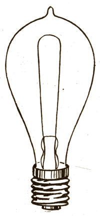
Fig. 23
Fig. 23
You will see that this lamp consists of a pear-shaped globe, and inside is a long U-shaped strip of carbon no thicker than an ordinary thread. This is a strip of bamboo cane[1] which has been carbonized to a thread of charcoal. It is joined to two wires which come through the glass. These two wires come down through the bottom of the globe, and one is fastened to a brass screw-ring, while the other wire is fastened to a brass button at the bottom of the lamp. These two (the ring and button) must, as you know, be separated from each other by something which[75] will not carry electricity, or they would make a short circuit when the electricity was applied. We separate the ring and the button in various ways.
You’ll notice that this lamp has a pear-shaped globe, and inside, there’s a long U-shaped strip of carbon that's no thicker than a common thread. This strip is made from bamboo that has been carbonized into charcoal thread. It’s connected to two wires that come through the glass. These two wires run down through the bottom of the globe, with one attached to a brass screw-ring and the other connected to a brass button at the bottom of the lamp. As you know, these two (the ring and button) need to be kept apart by something that doesn’t conduct electricity; otherwise, they would create a short circuit when the electricity is turned on. We use various methods to keep the ring and button separated.
Now, if we took the ends of two wires which were charged with the proper amount of electricity and put one wire on the screw-ring and the other on the button, the lamp would light up, because there would be a complete path for the current to travel in.
Now, if we took the ends of two wires that were charged with the right amount of electricity and connected one wire to the screw-ring and the other to the button, the lamp would turn on because there would be a complete path for the current to flow through.
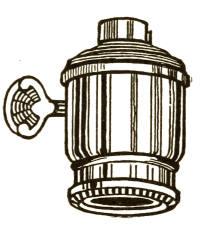
Fig. 24
Fig. 24
It will, however, be plain to you that it would be awkward to light the lamps in this way, so we use a "socket" into which the lamp is screwed. (Fig. 24.)
It will, however, be clear to you that it would be awkward to light the lamps this way, so we use a "socket" where the lamp is screwed in. (Fig. 24.)
The wires from the dynamo carrying the electricity are connected in the socket, one wire with the screw thread into which the screw-ring fits, and the other with a button which the button on the lamp touches when the lamp is screwed into the socket. Thus we have a connected path for the current to travel in, or, as it is termed, a complete circuit.
The wires from the dynamo that carry electricity are plugged into the socket, one wire fitted with the screw thread for the screw-ring, and the other with a button that the lamp's button presses against when you screw the lamp into the socket. This creates a connected path for the current to flow, known as a complete circuit.
You will notice that in the incandescent lamp the electricity does not need to jump, as it does in the arc-light, because we give it one continuous line to travel in.
You’ll see that in the incandescent lamp, electricity doesn’t have to jump like it does in the arc-light, because we provide it with one continuous path to follow.
In order, however, to get the current to do work for us, we put some resistance in its path, which it must overcome in order to travel back to the dynamo. The resistance in an incandescent lamp is the U-shaped carbon strip (or, as it is called, "filament"). This charcoal filament has so much greater resistance than the wires that it opposes, or resists, the passage of the electricity through it; but the electricity must go through, and, as it is strong enough to force its way, it overcomes this resistance and passes on through the carbon to the wire at the other end. You see it is a struggle between the carbon and the electricity, the current being determined to go on and the carbon trying to keep it back; and, in the end, the electricity, being the stronger, gets the best of it; but the struggle has been so hard that the carbon has been raised to a white heat, or incandescence, and so gives out a beautiful light, which continues as long as the current of electricity flows.
To make the current work for us, we add some resistance in its path that it has to overcome to return to the dynamo. The resistance in an incandescent lamp is the U-shaped carbon strip, also known as the "filament." This carbon filament has much greater resistance than the wires around it, which makes it resist the flow of electricity. But the electricity has to go through, and since it’s strong enough, it pushes its way past the resistance and travels through the carbon to the wire at the other end. It’s a struggle between the carbon and the electricity, with the current determined to move forward while the carbon tries to hold it back. In the end, the electricity, being stronger, prevails; however, the struggle generates so much heat that the carbon reaches a white-hot state, or incandescence, producing a beautiful light that lasts as long as the flow of electricity continues.
You will remember that in the arc-light the carbons are slowly consumed and new ones[77] must be put in. If the carbon in the incandescent light were consumed, it would not last many minutes, because it is only about the size of a horsehair. Now, you will naturally inquire why this fine strip is not burned up when it is raised to so high a heat. Well, we will tell you.
You will remember that in the arc-light, the carbon rods are gradually used up, and new ones[77] have to be replaced. If the carbon in the incandescent light was consumed, it wouldn’t last very long, because it’s only about the size of a horsehair. Now, you might wonder why this thin strip doesn’t get burned up even when it’s heated to such high temperatures. Well, we’ll explain that.
You know that if you light a match and let it burn the wood will all be consumed. But did you ever light a match, put it into a small bottle, and put the cork in? If you never did, do so now as an experiment, and you will see that the match will keep lighted for an instant and then go out without consuming the wood.
You know that if you light a match and let it burn, the wood will get completely consumed. But have you ever lit a match, put it in a small bottle, and sealed it with a cork? If you haven't, try it now as an experiment, and you'll see that the match will stay lit for a moment and then go out without burning up all the wood.
The reasons for this are very simple. In order to burn anything up entirely it is absolutely necessary to have the gas called oxygen present, and, as the air you live in contains a very large amount of oxygen, there is more than sufficient in your room to cause the wood of the match to be entirely consumed after it is lighted. But there is such a small quantity of oxygen in the bottle that it is not enough to keep the fire going in the match, and, consequently, it will not burn up the wood.
The reasons for this are straightforward. To completely burn something, you definitely need a gas called oxygen. Since the air around you has a lot of oxygen, there's more than enough in your room to fully burn the wood of the match once it’s lit. However, there's only a tiny amount of oxygen in the bottle, which isn't enough to keep the fire going in the match, so it won't burn the wood.
The reason the filament in an incandescent lamp is not burned up is because there[78] is no oxygen inside the globe. After the carbon is put in its place all the oxygen is drawn out through a tube, and the glass is sealed up so that no more oxygen can get in. This is called obtaining a "vacuum," and vacuum means a space without air.
The reason the filament in an incandescent lamp doesn’t burn out is that there[78] is no oxygen inside the bulb. Once the carbon is positioned, all the oxygen is removed through a tube, and the glass is sealed so that no more oxygen can enter. This process is known as creating a "vacuum," which refers to a space without air.
There being no oxygen in the globe, it is impossible for the carbon to burn up; so the incandescent lamp will continue to give its light for a very long time, some of them lasting for thousands of hours. Some day, however, from a great variety of obscure causes, the filament becomes weak in some particular spot and breaks, and the light ceases. When this happens, we unscrew the lamp and put another one in, and the light goes on as usual.
There’s no oxygen in the bulb, so the carbon can’t burn out; this means the incandescent lamp will keep shining for a long time, with some lasting for thousands of hours. Eventually, though, due to a range of unknown reasons, the filament gets weak in a specific spot and breaks, causing the light to go out. When this happens, we just unscrew the lamp and replace it, and the light comes back on like normal.
Now you have learned how the incandescent lamp is made to give light. We will add that it is a beautiful, soft, white light, almost without heat, it will not explode, throws off no poisonous fumes like gas or oil lamps, and has many other points of comfort and convenience which make it very desirable.
Now you know how the incandescent lamp produces light. It's a beautiful, soft, white light that generates almost no heat, won’t explode, doesn’t release any harmful fumes like gas or oil lamps, and has many other comfort and convenience features that make it really desirable.
ELECTRIC-LIGHT WIRES
Before closing the subject of electric light you would perhaps like to know something[79] about the way in which we place the wires leading to the lamps.
Before wrapping up the topic of electric light, you might want to know something[79] about how we run the wires to the lamps.

Fig. 25
Fig. 25
If you remember what we told you about measurements in the beginning of this book, it will be easy to understand what follows:
If you remember what we told you about measurements at the start of this book, it will be easy to understand what comes next:
You know that if you have a very great pressure you can force a quantity through a small conductor. This is the principle upon which the arc-lamps are run. Every arc-lamp takes about 40 to 50 volts and from 5 to 10 ampères to produce the light, and they are connected with the wires as shown in Fig. 25.
You know that if you have a lot of pressure, you can push a quantity through a small conductor. This is the principle on which the arc lamps operate. Each arc lamp requires about 40 to 50 volts and 5 to 10 amperes to produce light, and they are connected with the wires as shown in Fig. 25.
This is called running lamps in "series," and, as you will see from the sketch, the wire starts out from the dynamo and connects with one carbon of the first arc-lamp, and to the other carbon is connected another wire which goes on to the next lamp, and so on until[80] the last lamp is reached, and then the wire goes back to the dynamo. This forms, practically, one continuous loop from one brush to the other of the dynamo.
This is called running lamps in "series," and as you can see from the sketch, the wire starts from the dynamo and connects to one carbon of the first arc lamp. The other carbon connects to another wire that leads to the next lamp, and this continues until[80] the last lamp is reached. Then, the wire goes back to the dynamo. This essentially creates one continuous loop from one brush to the other of the dynamo.
The current starts out, makes its way through the first lamp, goes on to the next, makes its way through that, and so on till it has jumped the last one; then it goes back to the dynamo.
The current starts out, moves through the first lamp, continues to the next, passes through that, and keeps going until it has jumped the last one; then it returns to the dynamo.
Now, as each of these jumps requires a pressure of 40 or 50 volts, you will easily see that the total pressure, in volts, of the electricity must be as many times 40 or 50 volts as there are lamps to be lighted; so, if there were 60 lamps in circuit, there would be 2,400 to 3,000 volts pressure, which, while it gives very fine lights, might cause instant death to any one touching the wires.
Now, since each of these jumps needs a pressure of 40 or 50 volts, you can easily see that the total voltage of the electricity must be as many times 40 or 50 volts as there are lamps to be lit. So, if there were 60 lamps in the circuit, there would be 2,400 to 3,000 volts of pressure, which, while providing very bright lights, could instantly kill anyone who touches the wires.
Suppose anything happened to the first lamp, which stopped the current from jumping through it. There would be no path for the current to travel farther, and, consequently, all the lights would go out. To get over this difficulty there is sometimes used what is called a "shunt," which only acts when the lamp will not light. This shunt carries the current round the lamp to the other wire, so that it may travel on and light up the other lamps.
Suppose something happened to the first lamp, stopping the current from flowing through it. There would be no way for the current to continue, and as a result, all the lights would go out. To get around this issue, sometimes a "shunt" is used, which only activates when the lamp won't light. This shunt redirects the current around the lamp to the other wire, allowing it to keep going and light up the other lamps.
WIRES FOR INCANDESCENT LAMPS
The wiring for incandescent lamps is carried out in an entirely different way, which you can see by comparing Fig. 25 A with Fig. 25 which shows the wiring for arc-lamps.
The wiring for incandescent lamps is done in a completely different way, which you can see by comparing Fig. 25 A with Fig. 25, which shows the wiring for arc lamps.
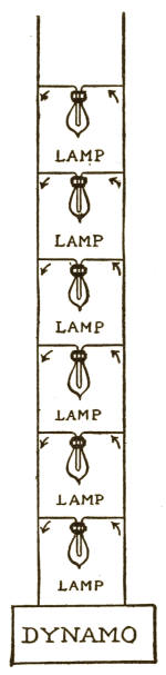
25 A
25 A
This is called connecting in "multiple arc."
This is called connecting in "multiple arc."
You will notice that the two wires running out from the dynamo (which are called the main wires) do not form one continuous loop as in the arc-light system, but that a smaller wire is attached to one of the main wires and then connected with the screw-ring in the lamp-socket; then another wire is connected with the button in the socket and afterward to the other main wire. Every lamp forms an independent path through which the current can travel back to the dynamo.
You’ll see that the two wires coming from the dynamo (known as the main wires) don’t create a single continuous loop like in the arc-light system. Instead, a smaller wire is attached to one of the main wires and connects to the screw-ring in the lamp socket. Then, another wire links to the button in the socket and connects to the other main wire. Each lamp creates its own separate path for the current to travel back to the dynamo.
Now, if we turn one of these incandescent lamps out, we simply shut off one of these paths and the electricity travels through the other lamps, and, if we wish, we can turn out all the lamps but one and there will still be a way for the electricity to go back to the dynamo.
Now, if we turn off one of these light bulbs, we just cut off one of the paths, and the electricity travels through the other bulbs. If we want, we can turn off all the bulbs except for one, and there will still be a way for the electricity to return to the generator.
In the arc-lamps we must have a very high number of volts pressure, because the electricity has only one path, and it all has to pass through the first and other lamps till it comes to the last one. In the incandescent light the electricity has as many paths as there are lamps, so we only need to keep one certain pressure in volts in the main wires all the time. This pressure is even all the way through the main wires, and, therefore, it is ready to light a lamp the instant it is turned on, because, as you have seen, electricity will always get back to the dynamo if there is a possible chance, and the lamp opens a path.
In arc lamps, we need a very high voltage because the electricity has only one path, and it has to pass through each lamp in order until it reaches the last one. In incandescent lights, electricity has as many paths as there are lamps, so we just need to maintain one specific voltage in the main wires at all times. This voltage is consistent throughout the main wires, so it’s ready to light a lamp the moment it’s turned on. As you can see, electricity will always return to the dynamo if there’s a chance, and the lamp creates a pathway.
The volts pressure used to operate any number of incandescent lamps is altogether very much less than for a number of arc-lights. For example, in the Edison system the pressure (sometimes called "electromotive force") is only about 110 volts, which is very mild and not at all dangerous. This[83] electromotive force would be the same if there were one lamp or ten thousand lighted.
The voltage needed to run any number of incandescent lamps is significantly lower than that required for several arc lights. For instance, in the Edison system, the voltage (often referred to as "electromotive force") is only about 110 volts, which is quite mild and completely safe. This[83] electromotive force would remain the same whether there is one lamp or ten thousand turned on.
While this Edison current would not hurt any one, you should remember that it is much the better plan not to touch any electric-light wires until you have learned a great deal more on this subject.
While this Edison current won’t harm anyone, you should remember that it’s much better not to touch any electric-light wires until you’ve learned a lot more about this subject.
We may add that each of the standard incandescent lamps requires only about one-quarter of an ampère of current to make them give a light of 16 candle-power, which is about the light given by a very good gas-jet, and while the electromotive force, or pressure, would only be about 110 volts, whether there were one lamp or ten thousand lighted, there must be sufficient ampères in the wires to give each lamp its proper quantity.
We should mention that each standard incandescent bulb needs only about a quarter of an amp of current to produce a brightness of 16 candle-power, which is similar to the light from a decent gas jet. The voltage required is about 110 volts, whether there is one bulb or ten thousand lit; however, there must be enough amps in the wires to supply each bulb with its proper amount.
SWITCHES
We have made mention several times of turning on or off one or more lights, and now, perhaps, you would like to know how this is done.
We’ve mentioned a few times about turning lights on or off, and now, maybe you want to know how to do that.
Suppose the electricity was traveling through wires to one or several lamps, it would light up those lamps as long as the wires provided a path to travel in, but if you were to cut out one of them, which is called[84] "breaking the circuit," there would be no road for the electricity to follow, and, consequently, its course would be stopped short and the lamps would go out. You will remember that electricity must have a complete circuit or it can do no work, and in electric lighting it is always a metallic circuit that is used.
If electricity is flowing through wires to one or more lamps, it will light up those lamps as long as the wires create a path for it to travel. However, if you cut one of the wires, known as[84] "breaking the circuit," there will be no path for the electricity to follow, and as a result, it will stop, causing the lamps to go out. Remember that electricity needs a complete circuit to work, and in electric lighting, a metallic circuit is always used.
Now, the switch is simply a device which is used to break the circuit so that the current cannot pass on. The simplest form of switch is seen in the sketch. (Fig. 26.)
Now, the switch is just a device used to break the circuit so that the current can't continue. The simplest form of switch is shown in the sketch. (Fig. 26.)
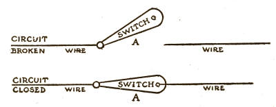
Fig. 26
Fig. 26
You will see that there is a wire cut in two, and to one piece is attached a metallic piece, A, which turns one way or the other, and when it is turned so as to touch the other part of the wire the circuit is closed and the electricity goes from the lower part of the wire through the metallic piece A to the other part of the wire, thus making a complete[85] circuit or path for the electricity to travel in.
You’ll notice that a wire is cut in two, and one piece has a metal part, A, attached to it. This part can move in either direction, and when it’s turned to touch the other piece of the wire, the circuit closes, allowing electricity to flow from the lower part of the wire, through metal piece A, to the other part of the wire, creating a complete[85] circuit for the electricity to travel.
If we turn the piece A away from the upper wire this breaks the circuit and cuts off the path, and, of course, the lamps would go out.
If we turn piece A away from the upper wire, it breaks the circuit and cuts off the path, so the lamps will go out.
This is the principle of the switch, and, although they are made in thousands of ways, switches all have the same object—namely, the closing and breaking of the circuit, whether it is for one or a hundred lamps.
This is the principle of the switch, and, although they come in thousands of designs, switches all serve the same purpose—closing and opening the circuit, whether it’s for one lamp or a hundred.
WIRE ON DYNAMOS
In explaining to you the construction and working of dynamo-machines, we did not state anything about the amounts of wire used in winding the machine.
In explaining how dynamo machines are built and operate, we didn't mention anything about the amount of wire used to wind the machine.
It is not our intention to say exactly how much is used on any one dynamo, because that is among the things you will have to learn when you come to study the subject of electricity more deeply.
It’s not our goal to specify exactly how much is used on any one dynamo, because that’s something you’ll need to figure out when you study electricity in more depth.
We simply want to have you understand that upon the number of turns of wire on any one machine depends the effect that that amount of wire, carrying electricity, will have upon a certain weight of iron when the armature is revolved a certain number of turns per minute.
We just want you to understand that the number of wire turns on any machine affects how that wire, which carries electricity, will interact with a specific weight of iron when the armature spins at a certain number of revolutions per minute.
A certain number of strands of wire on an armature will only do a certain amount of work at the most, so you will see that a small dynamo will not produce as much electricity as a larger one containing more iron and wire. For high pressure there must be more strands of wire cutting the lines of force more frequently than would be required for low pressure; and, to produce a great many ampères, the armature must be larger and the wire upon it thicker than it would need to be if only a small number of ampères were wanted.
A specific number of wire strands on an armature can only handle a limited amount of work, so you'll notice that a small dynamo generates less electricity than a larger one with more iron and wire. For high pressure, there needs to be more wire strands cutting through the lines of force more often than what's needed for low pressure. Additionally, to produce a high number of amperes, the armature has to be larger and the wire thicker than it would need to be if only a small number of amperes were required.
This of itself is a very deep and complicated subject, and many books have been written upon it alone. We shall, therefore, not attempt to go more deeply into it in this little book, but simply content ourselves with giving you the general idea, which will be sufficient until you make a thorough study of the subject.
This is a very deep and complicated topic, and many books have been written just about it. So, we won’t try to dive deeper into it in this short book. Instead, we'll just give you the general idea, which will be enough until you do a thorough study of the subject.
VIII
ELECTRIC POWER
Electricity
One of the most convenient uses to which electricity is put is in producing motive power for driving all kinds of machines, from a sewing-machine to a railway train, and we will now try to explain how we can get this kind of work from electricity.
One of the most convenient uses of electricity is to create power to run all sorts of machines, from a sewing machine to a train, and now we will explain how we can harness electricity for this kind of work.
To begin with, you all know that a piece of machinery is usually made to work by revolving a wheel which is part of the machine, either by means of a steam-engine or by water-power, or, as a sewing-machine, by foot-power. Now, when we work a piece of machinery by electricity we do just the same thing by using, instead of the steam-engine or water or foot power, an electric-engine called an "electromotor," which operates in the same way—namely, by turning the wheel of the machine it is applied to.
To start with, you all know that a piece of machinery typically operates by turning a wheel that is part of the machine, either using a steam engine, water power, or, like in a sewing machine, foot power. Now, when we run a piece of machinery with electricity, we do the same thing by using, instead of a steam engine, water, or foot power, an electric motor called an "electromotor," which works the same way—by turning the wheel of the machine it's attached to.
Foot-power is hard work for the person who is applying the power, and, as you can[88] easily see, one person can make only a very little power by use of the feet. Steam and water power can be used for any large amount of work, but the work must be within a few hundred feet of the engine or the power cannot be used.
Foot power is tough for the person using it, and as you can[88] easily see, one person can produce only a small amount of power with their feet. Steam and water power can be used for a lot of work, but the work needs to be within a few hundred feet of the engine, or the power can't be effectively utilized.
If there were a factory using steam-power a block or two away from where you lived, and you had a lathe in your house which you would like to have run by the steam-power in the factory, it would be practically impossible to do this. Now, if the factory were still farther away from your house, it would be still more impossible, and if it were a mile away it would be foolish to dream of taking steam-power from a place so far away.
If there was a factory using steam power a couple of blocks from where you lived, and you had a lathe at home that you wanted to run using the steam power from the factory, it would be nearly impossible to do this. If the factory were even farther from your house, it would be even more impossible, and if it were a mile away, it would be unrealistic to think about getting steam power from such a distant place.
Suppose, however, that this factory was lighted by electric lights, it would be a very easy matter to take some of the power over to your house. This could be done, even if the factory were miles away, by taking two wires from their electric-light wires and running them into your house to an electromotor connected with your lathe. This electromotor would then run your lathe just as well as if it were belted to a steam-engine.
Suppose, however, that this factory was lit by electric lights; it would be very easy to bring some of that power into your house. This could be done even if the factory was miles away, by connecting two wires from their electric-light lines and running them into your home to an electromotor linked to your lathe. This electromotor would then operate your lathe just as effectively as if it were connected to a steam engine.
So, you see, power can be carried in the form of electricity through two wires over[89] very great distances and made to do work at a long way from the engine which is turning the dynamo to make the electricity. Thus, you may have brought into your house wires which will give lights and, at the same time, power to run a sewing-machine, a lathe, or any other piece of machinery.
So, you see, power can be transmitted in the form of electricity through two wires over[89] very long distances and made to perform tasks far away from the engine that’s driving the generator to produce the electricity. So, you might have brought wires into your home that provide lighting and, at the same time, power to run a sewing machine, a lathe, or any other type of machinery.
Having learned so far that a dynamo will make a continuous current of electricity, and that two wires will carry this current to any place where it is wanted, let us now see what takes place in the electromotor to transform the electricity into power.
Having learned so far that a dynamo produces a continuous flow of electricity, and that two wires can transport this current to any desired location, let's now explore what happens in the electromotor to convert electricity into power.
An electromotor (which we will now call by its short name, motor) is simply a machine made like a dynamo. Curious as it may seem to you, it is a fact that if you take two dynamo-machines exactly alike, and run one with the steam-engine so as to produce electricity, and then take the two main wires and attach them to the brushes of the other dynamo, the electricity will drive this other dynamo so as to produce a great deal of power which could be used for driving other machines. Thus, the second dynamo would become a motor.
A motor is just a machine designed like a dynamo. It might sound strange, but if you take two identical dynamo machines, run one with a steam engine to generate electricity, and then connect the main wires to the brushes of the other dynamo, the electricity will power the second dynamo to produce a lot of energy that can be used to run other machines. In this way, the second dynamo turns into a motor.
In the chapter on dynamos we explained something about the way they were made and how the electricity was produced.
In the chapter on dynamos, we discussed how they were made and how the electricity was generated.
THE MOTOR
You will remember that the armature consists of a spool wound with wire. This spool is made of iron plates fastened together so as to form one solid piece. The armature of a motor may be made in the same way; in fact, the whole motor is practically a dynamo-machine.
You’ll remember that the armature is made up of a spool wrapped with wire. This spool is made of iron plates that are secured together to form a single solid piece. The armature of a motor can be constructed in the same way; in fact, the entire motor is essentially a dynamo machine.
There is something more about magnetism which we will tell you of here, because you will more easily understand it in its relation to an electromotor.
There’s more to magnetism that we’ll explain here, because it’ll be easier for you to understand in relation to an electromotor.
If we take an ordinary piece of iron and bring one end of it near to (but not touching) one pole of a magnet, this piece of iron will itself become a weaker magnet as long as it remains in this position. This is said to be magnetism by "induction." The end of the piece of iron nearest to the magnet will be of the opposite polarity. For instance, if the pole of the magnet were north, the end of the iron which was nearest to this north pole would be south, and, of course, the other end would be north. To make this more plain we show it in the following sketch. (Fig. 27.)
If we take a regular piece of iron and bring one end close to (but not touching) one pole of a magnet, this piece of iron will become a weaker magnet as long as it stays in that position. This phenomenon is called magnetism by "induction." The end of the iron closest to the magnet will have the opposite polarity. For example, if the magnet's pole is north, the end of the iron nearest to that north pole will be south, and the other end will be north. To clarify this, we show it in the following sketch. (Fig. 27.)
This would be the same whether the magnet were a permanent or an electromagnet.
This would be the same whether the magnet was a permanent magnet or an electromagnet.
You will remember also that the north pole of one magnet will attract the south pole of another magnet, but will repel a north pole.
You will remember that the north pole of one magnet will attract the south pole of another magnet, but will repel a north pole.
These are the principles made use of in an electromotor, and we will now try to show you how this is carried into practice.
These are the principles used in an electromotor, and we will now show you how this is put into practice.

STEEL PERMANENT MAGNET————
IRON————
Fig. 27
STEEL PERMANENT MAGNET IRON Fig. 27
Although a motor is made like a dynamo, we will show a different form of machine from the dynamo already illustrated, because[92] it will help you to understand more easily. (Fig. 28.)
Although a motor is built like a dynamo, we will present a different type of machine from the dynamo already shown, because[92] it will make it easier for you to understand. (Fig. 28.)
Here we have an electromagnet with its poles, and an iron armature wound with wire, just as in the dynamo we have described, except that its form is different.
Here we have an electromagnet with its poles, and an iron armature wrapped in wire, just like the dynamo we described, except that its shape is different.
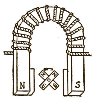
Fig. 28
Fig. 28
A commutator and brushes are also used, but the electricity, instead of being taken away from the brushes, is taken to them by the wires connected with them. Two wires are also connected which take part of the electricity around the magnet, just as in the dynamo.
A commutator and brushes are also used, but the electricity, instead of being taken away from the brushes, is brought to them by the wires connected to them. Two wires are also connected, which carry part of the electricity around the magnet, similar to how it works in a dynamo.
Now, when the volts pressure and ampères of electricity coming from a dynamo or battery are turned into the wires leading to the brushes of the motor, they go through the commutator into the armature and round the magnet, and so create the lines of force at the poles and magnetize the iron of the armature.
Now, when the voltage and current from a dynamo or battery flow through the wires leading to the motor brushes, they pass through the commutator into the armature and around the magnet, creating the lines of force at the poles and magnetizing the armature's iron.
Let us see what the effect of this is.
Let's see what the impact of this is.
The poles of the magnet become north and[93] south, and the four ends on the armature also become north and south, two of each.
The poles of the magnet turn into north and[93] south, and the four ends on the armature also become north and south, with two of each.
By referring to Fig. 28 again we shall see what takes place.
By looking at Fig. 28 again, we will see what happens.
The north pole of the magnet is doing two things: it is repelling, or forcing away, the upper north pole of the armature and at the same time drawing toward itself the lower south pole of the armature.
The north pole of the magnet is doing two things: it is repelling, or pushing away, the upper north pole of the armature while also attracting the lower south pole of the armature toward itself.
In the mean time the south pole of the magnet is repelling the south pole of the armature and at the same time drawing toward itself the north pole of the armature.
In the meantime, the south pole of the magnet is pushing away the south pole of the armature while simultaneously attracting the north pole of the armature.
This, of course, makes the armature turn around, and the same poles are again presented to the magnet, when they are acted upon in the same manner, which makes the armature revolve again, and this action continues as long as electricity is brought through the wires to the brushes. Thus, the armature turns around with great speed and strength, and will then drive a machine to which it is attached.
This, of course, makes the armature spin around, and the same poles are once again presented to the magnet, causing them to react in the same way, which makes the armature rotate again. This process keeps happening as long as electricity flows through the wires to the brushes. As a result, the armature spins quickly and powerfully, which then drives the machine it's connected to.
The speed and strength of the motor are regulated by the amount of iron and wire upon it, and by the volts pressure and ampères of electricity supplied to the brushes. Motors are made from a small size that will run a sewing-machine up to a size large[94] enough to run a railway train, and are often operated through wires at a great distance from the place where the electricity is being made, sometimes miles away.
The speed and strength of the motor are controlled by the amount of iron and wire in it, as well as by the voltage and amperage of electricity supplied to the brushes. Motors come in various sizes, from small ones that can power a sewing machine to large ones capable of running a train, and they are often operated via wires from far away, sometimes miles from where the electricity is generated.
They are also made in a great many different forms, but the principle is practically the same as we have just described to you.
They come in a lot of different shapes, but the basic idea is pretty much the same as what we just explained to you.
IX
BATTERIES
BATTERIES
So far we have only described one way of producing electricity—namely, by means of a dynamo-machine driven by steam or water power. The supply of electricity so obtained is regular and constant as long as the steam or water power is applied to the dynamo.
So far, we have only talked about one way to generate electricity—specifically, using a dynamo machine powered by steam or water. The electricity produced this way is steady and consistent as long as the steam or water power drives the dynamo.
There is another and very different way of producing electricity, and this is by means of a chemical process in what is called a battery.
There’s another and totally different way to generate electricity, and that’s through a chemical process in something called a battery.
To obtain electricity from the dynamo we must spend money for the coal to make the steam which operates the steam-engine, or for the water which turns the water-wheel, as well as for an engineer in both cases. When we obtain electricity from a battery we must spend money for the chemicals and metals which are constantly consumed in the battery.
To get electricity from the dynamo, we need to pay for coal to create the steam that runs the steam engine, or for the water that powers the water wheel, along with hiring an engineer in both cases. When we get electricity from a battery, we have to spend money on the chemicals and metals that are continually used up in the battery.
PRIMARY BATTERIES
An electrical battery is a device in which one or more chemical substances act upon a metal and a carbon, or upon two different metals, producing thereby a current of electricity, which will continue as long as there is any action of the chemicals upon the metal and carbon, or upon the two metals.
An electrical battery is a device that uses one or more chemical substances to react with a metal and carbon, or with two different metals, generating a flow of electricity. This current will keep going as long as the chemicals are actively reacting with the metal and carbon, or with the two metals.
Batteries for producing electricity may be divided into two classes, called "open circuit" batteries and "closed circuit" batteries.
Batteries for producing electricity can be divided into two types, known as "open circuit" batteries and "closed circuit" batteries.
Open-circuit batteries are those which are used where the electricity is not required constantly without intermission—for instance, in telephones, electric bells, burglar alarms, gas-lighting, annunciators, etc.
Open-circuit batteries are those used when electricity is not needed continuously without breaks—for example, in telephones, electric bells, burglar alarms, gas lighting, annunciators, etc.
Closed-circuit batteries are those which are used where the effect produced must be continuous every moment, as, for instance, in electric lights and motors.
Closed-circuit batteries are used in situations where a constant effect is required at all times, such as in electric lights and motors.
The open-circuit battery is made in many different ways, so we only describe two of the principal ones.
The open-circuit battery is made in various ways, so we will describe just two of the main ones.
As we told you in an early part of this book, we do not know just what electricity is, nor why it is produced under the conditions existing in a battery. But we do know[97] that by following certain processes and making certain chemical combinations we can make as much electricity and in such proportions as we want.
As we mentioned earlier in this book, we don’t know exactly what electricity is or why it’s generated under the conditions found in a battery. However, we do know[97] that by following specific processes and creating certain chemical combinations, we can produce as much electricity as we need, and in the proportions we want.
The two metals, or the metal and carbon, in a battery are called the "elements," and to these are connected the wires which lead from the battery to the instruments to be worked by it.
The two metals, or the metal and carbon, in a battery are called the "elements," and to these are connected the wires that lead from the battery to the instruments it powers.
The Leclanché Battery.—This form of open-circuit battery consists of a glass jar in which is placed the elements. One element consists of a rod of zinc, and the other element is carbon and powdered black oxide of manganese. These two (the carbon and black oxide of manganese) are placed in an earthenware vessel called a "porous cup." This is simply a small jar made of clay which is not glazed. Thus, the liquid which is in the glass jar penetrates through the porous cup to the carbon and manganese which it contains, and so the chemicals affect both these and the zinc at once, for, in order to obtain electricity, you will remember that the chemical action must take place at the same time upon both the elements in the same vessel. (Fig. 29.)
The Leclanché Battery.—This type of open-circuit battery consists of a glass jar that holds the elements. One element is a rod of zinc, while the other is made of carbon and powdered black oxide of manganese. These two (the carbon and black oxide of manganese) are placed in an unglazed clay container known as a "porous cup." This is simply a small jar made of clay. Therefore, the liquid in the glass jar seeps through the porous cup to reach the carbon and manganese inside, allowing the chemicals to interact with both the carbon and the zinc simultaneously. Remember, to generate electricity, the chemical reaction has to happen at the same time for both elements in the same vessel. (Fig. 29.)
The chemical substance used in this battery is sal-ammoniac, or salts of ammonia.[98] A certain quantity of this salt is dissolved in water, and this solution is poured into the glass jar. When this is done the battery will generate electricity at once.
The chemical substance used in this battery is sal-ammoniac, or salts of ammonia.[98] A specific amount of this salt is dissolved in water, and this solution is then poured into the glass jar. Once this is done, the battery will generate electricity immediately.
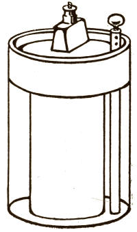
Fig. 29
Fig. 29
It should be remembered that the proper term for the chemical mixture which acts upon the elements in any battery is "electrolyte."
It should be remembered that the correct term for the chemical mixture that interacts with the elements in any battery is "electrolyte."
The Dry Battery.—The cleanliness, convenience, high efficiency, and comparatively low internal resistance of the dry cell has brought it into great favor in the last few years. It is now extensively used in preference to the Leclanché and other open-circuit batteries having liquid electrolyte for light work, such as bells, gas-lighting, burglar alarms, ignition on motor-boats, automobiles, etc.
The Dry Battery.—The cleanliness, convenience, high efficiency, and relatively low internal resistance of the dry cell have made it very popular in recent years. It is now widely used instead of the Leclanché and other open-circuit batteries with liquid electrolytes for lighter tasks like doorbells, gas lighting, burglar alarms, ignition in motorboats, and cars, etc.
The dry cell is also used in great numbers for pocket flash-lamps, and in other ways where it would be impossible to employ batteries containing liquids.
The dry cell is widely used in many pocket flashlights and other applications where it's not feasible to use liquid-filled batteries.
A dry cell consists of zinc, carbon, and the electrolyte, which is a mixture so made that it is in the form of a gelatinous or semi-solid mass, so that it will not run or slop over.
A dry cell is made up of zinc, carbon, and an electrolyte, which is mixed to form a gel-like or semi-solid substance so that it won't spill or overflow.
A piece of sheet zinc is formed into a long tube, and a round, flat piece of zinc is soldered at one end, thus making a cup open at one end. This forms the cell itself, and at the same time becomes one of the elements. The other element is a piece of battery carbon which is long enough to project out of the top of the cell about half an inch or more. While the cell is being filled with the electrolyte the carbon is held up by a support so that it does not touch the zinc at the bottom of the cup. Of course, the zinc cup and the carbon are provided with proper binding-posts or other attachments, so that conducting wires can be connected.
A piece of sheet zinc is shaped into a long tube, and a flat, round piece of zinc is soldered at one end, creating a cup that's open at one end. This forms the cell itself and also acts as one of the elements. The other element is a piece of battery carbon that's long enough to stick out of the top of the cell by about half an inch or more. While the cell is being filled with the electrolyte, the carbon is held up by a support so that it doesn’t touch the zinc at the bottom of the cup. Naturally, the zinc cup and the carbon have appropriate binding posts or other connections, allowing conducting wires to be attached.
The electrolyte is packed into the cup and around the carbon in such a way that the cup is entirely filled within about half an inch from the top, and then some melted tar or pitch is poured over the top of the electrolyte. This seals the cell and binds the contents solidly together. Just before the sealing compound hardens, one or two holes are made in it so that the gases may escape.
The electrolyte is packed into the cup and around the carbon so that the cup is completely filled up to about half an inch from the top, and then some melted tar or pitch is poured over the top of the electrolyte. This seals the cell and holds the contents tightly together. Just before the sealing compound hardens, one or two holes are made in it so that gases can escape.
The composition of the electrolyte itself is not exactly alike in all dry cells, as the various manufacturers follow their own particular formulas. However, as you may be curious to know something about it, we would state that one formula embraces flour, water, plaster of Paris, granulated carbon, zinc chloride, ammonium chloride, and manganese binoxide.
The makeup of the electrolyte isn’t the same in all dry cells, since different manufacturers have their own specific formulas. However, if you're interested in knowing more about it, we can share that one common formula includes flour, water, plaster of Paris, granulated carbon, zinc chloride, ammonium chloride, and manganese dioxide.
You will remember that the Leclanché and the dry batteries are purely open-circuit cells, and that they can be used to advantage for electric bells, annunciators, burglar alarms, gas ignition, etc., where the current of electricity is not doing continuous work, but only for a few seconds at a time. Consequently, the batteries have a little rest in between, if only for a few seconds.
You’ll recall that the Leclanché and dry batteries are purely open-circuit cells, and they’re great for electric bells, annunciators, burglar alarms, gas ignition, etc., where the flow of electricity isn’t doing continuous work, but only for a few seconds at a time. As a result, the batteries get a little break in between, even if it’s just for a few seconds.
Now, if we were to attempt to use open-circuit batteries for electric lights or motors, where the electricity must work constantly every second, the batteries would "polarize"—that is to say, they would only work a few minutes and then stop, because the chemicals used in them are of that kind that they will only allow the battery to do a little work at a time.
Now, if we tried to use open-circuit batteries for electric lights or motors, where the electricity needs to flow continuously every second, the batteries would "polarize"—meaning they would only function for a few minutes before stopping. This happens because the chemicals in them can only handle a small amount of work at a time.
The batteries we have been describing will do the ordinary work for which they are intended[101] for sometimes a year without requiring any attention, but if we try to make them do work for which they were not intended, they would only last a few days.
The batteries we've been talking about can handle the normal tasks they were designed for[101] for up to a year without needing any maintenance, but if we push them to perform tasks they weren't made for, they will only last a few days.
If we should want to operate electric lights or motors continuously from a battery we must, therefore, use
If we want to run electric lights or motors continuously from a battery, we must, therefore, use
CLOSED-CIRCUIT BATTERIES
There is a great variety of ways in which closed-circuit batteries are made, but, as the main principles are very much alike, we will only describe two general kinds, those with and those without a porous cup.[2]
There are many different methods for making closed-circuit batteries, but since the basic principles are quite similar, we will only cover two general types: those with a porous cup and those without.[2]
In the first place, we must state that closed-circuit batteries proper usually consist of a glass jar and two elements—carbon and zinc. Sometimes a porous cup is used; for what reason you will soon learn.
In the first place, we need to say that closed-circuit batteries usually consist of a glass jar and two elements—carbon and zinc. Sometimes a porous cup is used; you'll find out why soon.
The chemicals that are used are usually different from those used in the open-circuit batteries and are much stronger. These chemicals are usually sulphuric acid and bichromate[102] of potash (or chromic acid), which are mixed with water.
The chemicals used are typically different from those in open-circuit batteries and are much more powerful. These chemicals are usually sulfuric acid and potassium bichromate (or chromic acid), which are combined with water.
We will now examine two of the types of closed-circuit batteries, taking first the one without the porous cup, of which the Grenet is a good example.
We will now look at two types of closed-circuit batteries, starting with the one that doesn't have a porous cup, which the Grenet exemplifies.
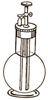
Fig. 30
Fig. 30
This battery, as you see, consists of a glass jar, in which are placed two plates of carbon and one of zinc. (Fig. 30.) The latter is between the two carbon plates and is movable up and down, so that it may be drawn up out of the solution when it is not desired to use the battery. When the zinc is in the solution there is a steady and continuous current of electricity developed, which can be taken away by wires from the connections on top of the battery.
This battery, as you can see, consists of a glass jar containing two carbon plates and one zinc plate. (Fig. 30.) The zinc plate is positioned between the two carbon plates and can be moved up and down, allowing it to be lifted out of the solution when the battery is not in use. When the zinc is submerged in the solution, a steady and continuous flow of electricity is generated, which can be accessed through wires connected to the top of the battery.
If the zinc were left in the solution when the battery was not in use, the acid would act upon it almost as much as though the electricity were not being used, and thus the zinc would be eaten away and the acid would be neutralized, so that no more action[103] could be had when we wanted more electricity.
If the zinc was left in the solution when the battery wasn’t in use, the acid would affect it almost as much as if the electricity wasn’t being used, causing the zinc to wear down and the acid to be neutralized, which would mean no more action[103] could take place when we wanted more electricity.
Now, in the Grenet battery we can light a lamp or run a motor for several hours continuously, but at the end of that time the solution would become black and it would do no more work. Then we must throw out that solution and put in fresh, and the battery will do the same work again, and so on.
Now, in the Grenet battery, we can power a lamp or run a motor for several hours straight, but after that time, the solution would turn black and wouldn't work anymore. Then we need to discard that solution and add a new one, and the battery will perform the same work again, and so on.
If you should only want to light your lamp or run your motor for a few minutes, you could pull the zinc up from the solution and put it down again when you wanted the electricity once more. The carbon element in the battery is not consumed by the acid, although the zinc is.
If you just want to turn on your lamp or run your motor for a few minutes, you can pull the zinc out of the solution and put it back in when you need electricity again. The carbon element in the battery isn’t used up by the acid, but the zinc is.
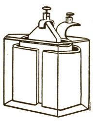
Fig. 31
Fig. 31
Now you will see the use of the porous cup. We will take as an illustration of this type an ordinary battery in which a porous cup is used. (Fig. 31.)
Now you'll see how the porous cup is used. We'll use a regular battery that features a porous cup as an example. (Fig. 31.)
Here, you will see, the carbon is placed in the porous cup, while the zinc is outside in the glass jar. In the glass cell with the zinc[104] is usually used water made slightly acid, and the strong solution of sulphuric acid and bichromate of potash (or chromic acid) is poured in the porous cup, where the carbon is placed.
Here, you'll notice that the carbon is put in the porous cup, while the zinc is kept outside in the glass jar. In the glass cell with the zinc[104], slightly acidic water is typically used, and a strong solution of sulfuric acid and potassium bichromate (or chromic acid) is poured into the porous cup where the carbon is located.
The strong solution penetrates the porous cup very slowly and gets to the zinc, when it immediately produces a current of electricity. But the acid does not get at the zinc so freely as it does in the battery without a porous cup, and, consequently, neither the acid nor the zinc is so rapidly used up.
The strong solution slowly seeps through the porous cup and reaches the zinc, which immediately generates an electric current. However, the acid doesn't interact with the zinc as easily as it does in a battery without a porous cup. As a result, neither the acid nor the zinc is consumed as quickly.
Where porous cups are used, the batteries will give a continuous current for a very much longer time than without them, and will, sometimes, give many hours' work every day for several months without requiring any change of solution.
Where porous cups are used, the batteries will provide a continuous current for a much longer time than without them and will, at times, deliver several hours of work every day for several months without needing any change of solution.
Polarization.—There is one other reason why a longer working time can be had from a battery with a porous cup, and that is, in a battery without a porous cup the action of the acid upon the zinc is so rapid that the carbon plates become covered with gas, and, therefore, the proper action by the acid cannot take place upon them. Thus, the battery ceases to work, and is said to be "polarized." When a porous cup is used, the action of the acid upon the zinc is slow enough to give off[105] only a small amount of gas, and thus the acid has a chance to act upon the carbon plates and develop a steady current of electricity.
Polarization.—Another reason why a battery with a porous cup can operate longer is that in a battery without a porous cup, the acid reacts with the zinc so quickly that the carbon plates get covered with gas, preventing the acid from working effectively on them. As a result, the battery stops functioning, which is referred to as being "polarized." When a porous cup is used, the acid reacts with the zinc slowly enough to produce only a small amount of gas, allowing the acid to effectively act on the carbon plates and generate a steady flow of electricity.
THE WORK DONE BY BATTERIES
The pressure and quantity of electricity given off continuously by open and closed circuit batteries is very different.
The pressure and amount of electricity produced continuously by open and closed circuit batteries is very different.
The pressure (or "electromotive force") of one cell of an ordinary open-circuit battery is only about one volt, and the current is usually very much less than one ampère, except in a dry cell, which may give more.
The voltage (or "electromotive force") of a single cell from a standard open-circuit battery is only about one volt, and the current is usually well below one ampere, except for a dry cell, which can provide more.
In the closed-circuit batteries described, the electromotive force of each cell is about two volts, while the current varies from 1 to perhaps 50 ampères, according to the size of the zinc and carbon plates.
In the closed-circuit batteries described, the voltage of each cell is about two volts, while the current ranges from 1 to maybe 50 amps, depending on the size of the zinc and carbon plates.
It would not matter if you made one cell as big as a barrel, nor if you put in a dozen carbons and zincs, the electromotive force would not exceed the volts mentioned for each type of battery, but the ampère capacity would be greater than in a smaller cell on account of the larger size of the carbon and zinc plates.
It wouldn't make a difference if you made one cell as big as a barrel, or if you added a dozen carbons and zincs; the electromotive force wouldn't exceed the volts specified for each type of battery, but the ampere capacity would be higher than in a smaller cell because of the larger size of the carbon and zinc plates.
Internal Resistance.—There is one other point which affects the number of ampères[106] which can be obtained from a closed-circuit battery, and that is whether there is a large or small internal resistance in the battery itself.
Internal Resistance.—There's another factor that influences the number of ampères[106] that can be drawn from a closed-circuit battery, and that is the level of internal resistance within the battery itself.
This depends upon the solution which is used and the arrangement of the plates.
This depends on the solution used and the arrangement of the plates.
If there is a high resistance in the battery itself (called "internal resistance"), the electricity must do work to overcome this resistance before it can get out of the battery to do useful work through the wires, and, consequently, the capacity in ampères is limited.
If there’s high resistance in the battery itself (known as "internal resistance"), the electricity has to work to overcome this resistance before it can flow out of the battery to perform useful tasks through the wires. As a result, the capacity in amperes is limited.
If, on the other hand, there is very little resistance in the battery, the current has very little work to flow to the wires leading from the battery, and we can get a larger quantity, or greater number of ampères.
If, however, there’s very little resistance in the battery, the current has minimal work to do in flowing through the wires connected to the battery, which allows us to draw a larger amount or greater number of amperes.
Thus, you will see that while the closed-circuit battery is the stronger, and will do all that the open-circuit battery will do, and even more, in a short time the latter, though weaker, will do about as much work for the same amount of zinc and carbon as the former, but takes a much longer time.
Thus, you will see that while the closed-circuit battery is stronger and can do everything the open-circuit battery can do—and even more—in a short time, the latter, although weaker, will perform about the same amount of work for the same amount of zinc and carbon as the former, but it takes a much longer time.
BATTERIES FOR ELECTRIC LIGHT
As we have explained to you, closed-circuit batteries are used for producing incandescent[107] electric lights in small numbers, as well as for running motors.
As we've explained to you, closed-circuit batteries are used to produce incandescent[107] electric lights in small quantities, as well as to power motors.
To operate incandescent lights, a number of batteries connected together are used. The number used depends upon the pressure which the lamps require to make them give the required light. We will now explain how the batteries are connected together for this purpose.
To power incandescent lights, several batteries are connected together. The number of batteries used depends on the voltage that the lamps need to produce the desired brightness. Now, we will explain how the batteries are connected for this purpose.
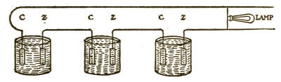
Fig. 32
Fig. 32
Suppose you wished to light an incandescent lamp of, say, three candle-power, which required six volts. We would take three closed-circuit batteries which would each give two volts, and connect by a piece of wire the zinc of the first to the carbon of the second, and the zinc of the second to the carbon of the third, as shown in the sketch. (Fig. 32.)
Suppose you want to power a 3-candle-power incandescent bulb that needs 6 volts. We would use three closed-circuit batteries, each providing 2 volts, and connect them with a wire, linking the zinc of the first battery to the carbon of the second, and the zinc of the second to the carbon of the third, as illustrated in the sketch. (Fig. 32.)
We would then attach a wire to the carbon of the first and one to the zinc of the third, and there would be six volts in these two[108] wires, which would light up one six-volt lamp nicely.
We would then connect a wire to the carbon of the first and another to the zinc of the third, and there would be six volts in these two[108] wires, which would light up a six-volt lamp nicely.
This is called connecting in series, or for intensity.
This is called connecting in series, or for intensity.
Now if each of these cells gave ten ampères alone, the three will only give ten ampères together when they are connected in series.
Now, if each of these cells provided ten amperes individually, the three of them will only provide ten amperes together when they are connected in series.
If our lamp only required one ampère, you would naturally think that ten similar lamps put on the wires would give as good light as the one, but that is not so.
If our lamp only needed one amp, you would naturally think that ten similar lamps connected would provide the same light as one, but that’s not the case.
Although you might light up two lamps, the pressure would drop and the lights would become less brilliant if you put on the whole number. So, if we wished to put on the whole ten lights we would connect another battery and thus increase the pressure, which would probably make these ten lamps burn brightly.
Even if you turn on two lamps, the pressure would drop and the lights would become dimmer if you turned on all of them. So, if we wanted to turn on all ten lights, we would connect another battery to increase the pressure, which would likely make the ten lamps shine brightly.
These rules hold good for connecting any number of batteries for lamps of any number of volts—that is to say, there should be calculated about two volts for each cell and an allowance made for drop in pressure.
These rules apply for connecting any number of batteries to lamps of any voltage. In other words, you should calculate about two volts for each cell and account for the drop in pressure.
CONNECTING IN MULTIPLE
There is another way of connecting batteries, and that is to obtain a larger number[109] of ampères. This is called connecting in multiple arc, or for quantity.
There’s another way to connect batteries, which is to get a higher number[109] of amperes. This is known as connecting in multiple arc, or for quantity.
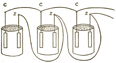
Fig. 33
Fig. 33
Let us take again for an illustration the three cells giving each 2 volts and 10 ampères. This time we connect the carbon of the first to the carbon of the second, and the carbon of the second to that of the third; then we connect the zinc of the first to that of the second, and the zinc of the second to that of the third, as shown in the sketch. (Fig. 33.)
Let’s use the same example again with the three cells, each providing 2 volts and 10 amperes. This time, we connect the carbon of the first cell to the carbon of the second, and the carbon of the second to the carbon of the third. Next, we connect the zinc of the first cell to the zinc of the second, and the zinc of the second to the zinc of the third, as shown in the illustration. (Fig. 33.)
We then attach a wire to the zinc and one to the carbon in the third cell, and we then can obtain from these two wires only 2 volts, but 30 ampères.
We then connect a wire to the zinc and another to the carbon in the third cell, and from these two wires, we can get only 2 volts, but 30 amps.
There are, again, many ways of connecting several of these sets together, but it is not[110] intended in this book to go into these at length, for the reason that we only set out to give a simple explanation of the first principles of this subject.
There are, again, many ways to connect several of these sets together, but it is not[110] the purpose of this book to explore them in detail, because we only aim to provide a straightforward explanation of the basic principles of this subject.
We shall therefore only give an illustration of one more method of connecting batteries which will be easy to understand. This is called
We will only provide one more example of how to connect batteries, which will be simple to understand. This is called
MULTIPLE SERIES
The sketch we have last given shows three batteries connected in multiple. These we will call set No. 1.
The sketch we provided last shows three batteries connected in parallel. We'll refer to these as set No. 1.
Now, suppose we take three more batteries exactly similar and connect them together just in the same manner. Let us call this set No. 2. Now take the wire leading from the carbon of set No. 2 and connect it with the wire leading from the zinc of set No. 1. Then take a wire leading from the zinc of set No. 2, and a wire leading from the carbon of set No. 1, and connect them with the lamps or motors. These two sets being connected in multiple series, we shall get 4 volts and 30 ampères.
Now, let's take three more batteries that are exactly the same and connect them together in the same way. We'll call this set No. 2. Next, take the wire from the carbon of set No. 2 and connect it to the wire from the zinc of set No. 1. Then, take a wire from the zinc of set No. 2 and a wire from the carbon of set No. 1, and connect them to the lamps or motors. With these two sets connected in series, we will achieve 4 volts and 30 amps.
This is called connecting in multiple series, and may be extended indefinitely with any number of batteries.
This is referred to as connecting in multiple series and can be extended indefinitely with any number of batteries.
We should add that one of the elements in[111] a battery is called "positive," and the other "negative."
We should add that one of the elements in[111] a battery is called "positive," and the other is called "negative."
THE EDISON PRIMARY BATTERY
As this type of battery will work efficiently on either open or closed circuit, we have thought best to describe it separately at this place, in order not to confuse your ideas while reading about batteries generally.
Since this type of battery works effectively in either open or closed circuits, we thought it would be best to describe it separately here, so as not to confuse your understanding while you read about batteries in general.
The type of cell we will now describe was originated by an inventor named Lalande, and was known by that name; but it has been greatly improved and rendered more efficient by Edison, and is now manufactured and sold by him under the name of the Edison Primary Battery.
The type of cell we're going to describe was created by an inventor named Lalande, and it was known by that name; however, it has been greatly improved and made more efficient by Edison, and is now produced and sold by him as the Edison Primary Battery.
Before describing the cell itself, let us consider the action that takes place in a battery of this kind.
Before we describe the cell itself, let's look at what happens in a battery like this.
If certain metals are placed in a suitable solution, and are connected together, outside of the solution, by wires, vigorous chemical action will take place at the surfaces of the metals, and electrical energy will be produced. The plates must be of different metals, and the solution should be one that will dissolve neither of them except when an electric current is allowed to flow.
If certain metals are put into a compatible solution and linked together outside of the solution with wires, a strong chemical reaction will occur at the surfaces of the metals, generating electrical energy. The metals need to be different, and the solution should be one that won’t dissolve either of them unless an electric current is allowed to flow.
One of the metals is usually zinc, which is gradually eaten away or dissolved by the solution while the battery is delivering electrical energy. It is the chemical combination of the zinc and the solution that produces this energy, which leaves the zinc in the form of an electric current, and passes through the solution to the other metal, out of the cell to the wire, and thence back by another wire to the zinc, where it is once more started on its circuit.
One of the metals is usually zinc, which is gradually worn away or dissolved by the solution while the battery is providing electrical energy. It's the chemical reaction between the zinc and the solution that creates this energy, which turns the zinc into an electric current. This current flows through the solution to the other metal, out of the cell to the wire, and then back through another wire to the zinc, restarting its circuit.
At the surface of the other metal, which may be, and frequently is, copper, small bubbles of the gas called hydrogen are produced. This gas rises to the surface of the liquid and gradually passes off into the air. But its presence offers resistance to the passage of the current; so that generally there is associated with the copper a supply of the gas oxygen. Oxygen and hydrogen are always very eager to mix with each other, and, therefore, when the hydrogen bubbles appear they are quickly taken up by the oxygen near by. The mixture of these two gases forms water, which becomes part of the solution. All of this happens so quickly that the hydrogen cannot be perceived so long as there is any oxygen left in the copper-oxide plate.
At the surface of the other metal, which is often copper, small bubbles of hydrogen gas are produced. This gas rises to the surface of the liquid and gradually escapes into the air. However, its presence creates resistance to the flow of the current; so there is usually oxygen gas associated with the copper. Oxygen and hydrogen are always eager to combine, and when the hydrogen bubbles appear, they are quickly absorbed by the nearby oxygen. The combination of these two gases forms water, which becomes part of the solution. This all happens so quickly that the hydrogen isn't noticeable as long as there is any oxygen left in the copper-oxide plate.
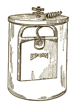
Fig. 34
Fig. 34
In the Edison Primary Battery (Fig. 34) the plates are zinc, known as the negative, and copper oxide (copper and oxygen), or the positive. These are suspended in a solution of caustic soda and water, the plates and solution being contained in jars of glass or porcelain. The plates are provided with suitable wires for connecting the cells with one another and with the lamps, motors, or other devices which they are to operate. There are usually two zinc plates and one copper-oxide plate, or multiples thereof. The quantity of current that may be withdrawn depends on the size and number of the plates, as well as upon their construction and arrangement.
In the Edison Primary Battery (Fig. 34), the plates are made of zinc, which is the negative plate, and copper oxide (copper and oxygen), which is the positive plate. These plates are immersed in a solution of caustic soda and water, and they are housed in jars made of glass or porcelain. The plates are fitted with appropriate wires to connect the cells to each other and to the lamps, motors, or other devices they are meant to power. Typically, there are two zinc plates and one copper-oxide plate, or multiples of those. The amount of current that can be drawn depends on the size and number of the plates, as well as their design and arrangement.
The voltage of these cells is low, being about 0.65 volt each; but this is more than compensated for by the fact that the internal resistance of the battery is so low that the voltage is not perceptibly affected even at continuous high-discharge rates, and that the voltage remains practically constant throughout the life of the cell.
The voltage of these cells is low, around 0.65 volts each; but this is more than offset by the low internal resistance of the battery, which means that the voltage isn’t noticeably impacted even at continuous high-discharge rates, and the voltage stays nearly constant throughout the cell’s life.
Furthermore, when the battery is not in[114] use there is practically no local action. Consequently, the cells may remain on open circuit (that is, doing no work) for years and there will be no loss of energy. The cell will then operate with the same practical efficiency as if it were new. In some classes of work this battery remains in service from four to six years without attention.
Furthermore, when the battery isn’t in[114] use, there’s almost no local action. As a result, the cells can stay on open circuit (meaning they’re not doing any work) for years without losing energy. The cell will then work with the same practical efficiency as if it were brand new. In some types of work, this battery can remain in use for four to six years without any maintenance.
Another peculiar advantage of this battery lies in the fact that the plates and the electrolyte are so well proportioned that they are all exhausted at the same time, and then new plates and solution can be put in the jar, restoring it to its original condition. These batteries are used in great numbers for railway signal work and for other purposes, such as fire and burglar alarm systems, various telephone functions, operation of electric self-winding and programme clock systems, small electric-motor work, for low candle-power electric lamps, gas-engine ignition, electro-plating, telegraph systems, chemical analysis, and other experimental work where batteries are required that will remain in use for long periods of time without requiring any attention or renewal.
Another unique advantage of this battery is that the plates and the electrolyte are so well balanced that they get depleted at the same rate, allowing for new plates and solution to be added to the jar, restoring it to its original state. These batteries are widely used for railway signaling and other applications, such as fire and burglar alarm systems, various telephone functions, operating electric self-winding and programmable clock systems, small electric motor tasks, low-power electric lamps, gas engine ignition, electroplating, telegraph systems, chemical analysis, and other experimental work where long-lasting batteries are needed without the need for frequent maintenance or replacement.
The remarks that have been made on previous pages about connecting up batteries in series, multiple, and multiple series apply[115] also to these Edison Primary Cells. Fig. 35 shows a battery of four of these cells connected in series.
The comments made on previous pages about connecting batteries in series, parallel, and parallel series also apply[115] to these Edison Primary Cells. Fig. 35 shows a battery of four of these cells connected in series.
SECONDARY, OR STORAGE, BATTERIES
The open and closed circuit batteries we have so far described are used to produce electricity by the action of the chemicals upon the elements contained in them. They are called primary batteries.
The open and closed circuit batteries we've described so far generate electricity through the chemical reactions involving the elements inside them. They are known as primary batteries.
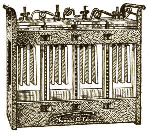
Fig. 35
Fig. 35
The batteries which we will now tell you of are called secondary, or storage, batteries, and do not of themselves make any primary current, but simply act as reservoirs, so to speak, to hold the energy of the electric current which is led into them from a dynamo or primary battery. At the proper time and under proper conditions these secondary batteries will give back a large percentage of the energy[116] of the electric current which has been stored in them.
The batteries we’re about to discuss are known as secondary or storage batteries. They don’t generate any primary current on their own; instead, they serve as reservoirs to store the energy from an electric current supplied by a dynamo or primary battery. When the right conditions are met, these secondary batteries can release a significant percentage of the stored energy from the electric current. [116]
This class of battery has been called by these three names: "secondary battery," "accumulator," and "storage battery"; but as the latter name is used almost exclusively in this country, we shall use it in the following description.
This type of battery is known by three names: "secondary battery," "accumulator," and "storage battery"; however, since the last name is used almost exclusively in this country, we will use it in the following description.
TWO TYPES
There are two distinct types of storage battery. One is called the "lead" or "acid" storage battery, and the other the "alkaline" or "nickel-iron" storage battery. Each of them simply acts as a reservoir to hold the energy of the electric current which is led into it, and each of them, under proper conditions, will give back that energy. As the lead storage battery is the oldest in point of discovery and invention, we will describe it first.
There are two main types of storage batteries. One is called the "lead" or "acid" storage battery, and the other is the "alkaline" or "nickel-iron" storage battery. Both act as a reservoir to hold the energy of the electric current that flows into them, and under the right conditions, they can release that energy. Since the lead storage battery is the oldest in terms of discovery and invention, we'll describe it first.
THE LEAD STORAGE BATTERY
A lead storage battery usually consists of a glass or hard-rubber jar containing lead plates and a solution consisting of water and sulphuric acid. A single unit is usually called a "cell." (Fig. 36.)
A lead storage battery typically consists of a glass or hard rubber container that holds lead plates and a solution made of water and sulfuric acid. Each individual unit is usually referred to as a "cell." (Fig. 36.)
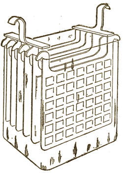
Fig. 36
Fig. 36
We have, then, a glass or hard-rubber jar containing two lead plates and a solution consisting of water and sulphuric acid. These plates are called the "elements," and one is called the positive and the other the negative element. The solution is called the "electrolyte."
We have a glass or hard-rubber jar that holds two lead plates and a solution made of water and sulfuric acid. These plates are referred to as the "elements," with one being the positive element and the other the negative element. The solution is known as the "electrolyte."
The positive element is a sheet of lead upon which is spread a paste made of red-lead. The negative element is a similar sheet of lead upon which is spread a paste made of litharge.
The positive element is a sheet of lead covered with a paste made of red lead. The negative element is a similar sheet of lead covered with a paste made of litharge.
Now, when these plates are thus prepared, they are put into the acid solution in the jar, and a wire attached to each plate is connected with the two wires from a dynamo or other source of electric current, just as a lamp would be connected.
Now, when these plates are prepared like this, they're placed into the acid solution in the jar, and a wire attached to each plate is connected to the two wires from a generator or another source of electric current, just like a lamp would be connected.
The electric current then goes into the storage-battery cell, entering by the positive plate and coming out by the negative. These plates and the paste upon them offer some resistance, or opposition, to the passage of the current, so the electricity must do some work to get from one to the other. The work it does in this case is to so act upon the paste that its chemical nature is changed.
The electric current then flows into the storage battery cell, entering through the positive plate and exiting through the negative one. These plates and the paste on them provide some resistance to the flow of current, so the electricity has to do some work to move from one to the other. In this case, the work it performs changes the chemical nature of the paste.
So, after the primary current has been passed from one plate to the other for some time, and after several "discharges," the storage battery may be disconnected, being now "formed."
So, after the main current has been passed from one plate to the other for a while, and after several "discharges," the storage battery can be disconnected, as it is now "formed."
The paste on the lead plates is now found to have changed its chemical nature, the paste on the positive plate having been transformed into peroxide of lead, and that on the negative plate into spongy lead. On arriving at this condition, the paste on the plates is called "active material."
The paste on the lead plates is now discovered to have changed its chemical makeup, with the paste on the positive plate turning into lead peroxide, and that on the negative plate becoming spongy lead. When it reaches this state, the paste on the plates is referred to as "active material."
This process of "formation" is absolutely essential before the lead storage battery is[119] ready to be used for actual work. So, when the plates have been fully "formed," the storage battery may be again connected with a source of electric current which again enters by the positive plate and leaves by the negative. This current so acts on the active material that it combines with the acid solution and, through the energy of the charging current, forms other chemical compounds which may for convenience be called "sulphates." When the charging current has flowed through the battery long enough to produce these changes in the active material the battery is said to be "charged," and is ready for useful work.
This "formation" process is crucial before the lead storage battery is[119] ready for actual use. Once the plates are fully "formed," the storage battery can be reconnected to a source of electric current, which enters through the positive plate and exits through the negative. This current interacts with the active material, combining with the acid solution and, through the energy from the charging current, creating other chemical compounds that we can conveniently call "sulphates." When the charging current has flowed through the battery long enough to bring about these changes in the active material, the battery is considered "charged" and ready for practical use.
If the two wires attached to the plates are now connected with electric lamps, or a motor, or other device, the active material will develop energy in the effort to again change its nature. This energy takes the form of an electric current, which leaves the battery and passes through the conductors and operates the lamps, motors, or other devices in its passage.
If the two wires connected to the plates are now hooked up to electric lamps, a motor, or another device, the active material will generate energy as it tries to change back to its original state. This energy is released as an electric current, which flows out of the battery, travels through the wires, and powers the lamps, motors, or other devices along the way.
In this way the battery is said to be "discharged," and at the end of its discharge it can again be charged and discharged in a similar manner for a long time, until the active material is either used up or drops off the plates.
In this way, the battery is said to be "discharged," and once it's fully discharged, it can be recharged and discharged in a similar way for a long time, until the active material is either exhausted or falls off the plates.
So far as the actual details of construction are concerned, lead storage batteries are made in a great many different ways, but the materials are, in general, of the same nature as those we have mentioned above.
As for the specifics of how they're built, lead storage batteries are made in a lot of different ways, but the materials are generally similar to those we've talked about earlier.
THE ALKALINE STORAGE BATTERY
We shall now describe an entirely different type of storage battery, which contains neither lead nor acid. It is one of the many inventions of Thomas A. Edison.
We will now describe a completely different type of storage battery that doesn't contain lead or acid. It's one of the many inventions by Thomas A. Edison.
In the alkaline storage battery the gas called oxygen plays a very important part, and we will try to make it clear to you what this part is.
In the alkaline battery, oxygen gas plays a crucial role, and we'll explain what that role is.
You are well aware of the fact that if you leave your pocket-knife out in the air it will get rusty. The reason for this is that iron or steel quickly tends to combine with the oxygen of the air, and this combination of oxygen and iron is rust, otherwise called oxide of iron, or iron oxide.
You know that if you leave your pocket knife out in the open, it will get rusty. This happens because iron or steel quickly reacts with the oxygen in the air, and this reaction between oxygen and iron produces rust, which is also known as iron oxide.
This iron oxide, or rust, is therefore the result of a chemical action between the iron and the oxygen.
This iron oxide, or rust, is basically the result of a chemical reaction between iron and oxygen.
Now as all chemical actions require the expenditure of energy, there has been developed either heat or electricity in the process.[121] The oxygen may be taken away from the iron oxide, chemically; but here again would be another chemical action which would require energy to be once more expended.
Now, since all chemical reactions need energy, either heat or electricity is produced during the process.[121] Oxygen can be removed from iron oxide chemically, but this would involve another chemical reaction that would also require energy.
Iron oxide may be made chemically in many different ways. It is frequently made in the form of a powder. Therefore, we do not have to depend upon iron rust for a supply of this material.
Iron oxide can be produced chemically in various ways. It is often created as a powder. This means we don't have to rely on iron rust for a source of this material.
Before going further we must consider another oxide—namely, nickel oxide. It is characteristic of nickel that when it is combined with oxygen to a certain degree so as to form the compound known as nickel oxide, it will receive still more oxygen.
Before we go any further, we need to think about another oxide—specifically, nickel oxide. Nickel has the unique property that when it combines with oxygen to a certain extent and forms the compound called nickel oxide, it can take on even more oxygen.
Now, if under proper conditions we compel iron oxide to give up its oxygen to some other kind of chemical compound, such as nickel oxide, we must expend energy. But, on the other hand, if this nickel oxide gives back the oxygen to the iron—which it will do if opportunity is given—there is energy produced again in receiving the oxygen. In other words, the energy previously expended, or part of it, is now returned.
Now, if we force iron oxide to release its oxygen to another chemical compound, like nickel oxide, we have to use energy. However, if that nickel oxide returns the oxygen to the iron—which it will if given the chance—energy is produced again when it receives the oxygen. In other words, some of the energy we initially spent is now returned.
This action and reaction are practically those that take place in the Edison alkaline storage battery. For simplicity of illustration[122] we will consider a cell containing only two plates, one positive and one negative.
This action and reaction are essentially the same as those that occur in the Edison alkaline storage battery. To keep it simple[122], we'll look at a cell with just two plates, one positive and one negative.
The negative plate is made up of a number of small, flat, perforated pockets containing iron oxide in the form of a fine powder. The positive plate is made up of small, perforated tubes containing nickel oxide mixed with very thin flakes of metallic nickel. (Fig. 37 illustrates these plates, the positive being in front.)
The negative plate consists of several small, flat, perforated pockets filled with iron oxide as a fine powder. The positive plate is made up of small, perforated tubes filled with nickel oxide mixed with very thin flakes of metallic nickel. (Fig. 37 illustrates these plates, with the positive one in front.)
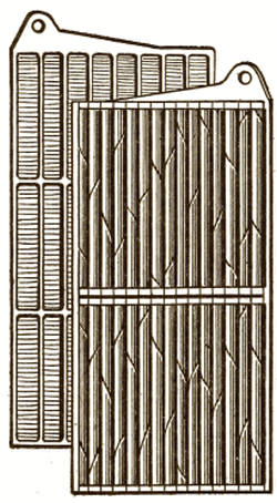
Fig. 37
Fig. 37
These two elements, positive and negative, having wires or conductors attached, are placed in a nickeled-steel can containing the electrolyte, which consists of a potash solution. You will see that this differs from a lead storage battery, in which the electrolyte is sulphuric acid and water. If we were to put this acid solution into a metallic can (except one made of lead) the can would not last long, as the acid would quickly eat holes through it.
These two elements, positive and negative, with wires or conductors attached, are placed in a nickeled-steel can that holds the electrolyte, which is a potash solution. You'll notice that this is different from a lead storage battery, where the electrolyte is a mixture of sulfuric acid and water. If we were to put this acid solution in a metal can (other than one made of lead), the can wouldn't last long because the acid would quickly eat through it.
Now let us see what takes place in the[123] Edison alkaline storage battery. If an electric current from a dynamo or other source of electricity is caused to pass through the positive to the negative plate the oxygen present in the iron oxide passes to and remains with the nickel oxide. During all the time this is going on the battery is said to be "charging," and when all the oxygen has been removed from the iron oxide and is taken up by the nickel oxide, then the battery is said to be "charged," and the flow of current into the battery is stopped.
Now let's take a look at what happens in the[123] Edison alkaline storage battery. When an electric current from a dynamo or another power source flows from the positive to the negative plate, the oxygen in the iron oxide moves to and bonds with the nickel oxide. While this process is happening, the battery is considered to be "charging," and once all the oxygen has been transferred from the iron oxide to the nickel oxide, the battery is deemed "charged," and the flow of current into the battery stops.
A change has now taken place. The powder in the negative plate is no longer iron oxide, but has been reduced to metallic iron, because the oxygen has been removed. The powder in the positive plate is now raised to a higher or super oxide of nickel, because it has taken the oxygen that was in the iron.
A change has now occurred. The powder in the negative plate is no longer iron oxide but has been transformed into metallic iron, as the oxygen has been removed. The powder in the positive plate has now turned into a higher or super oxide of nickel because it has taken on the oxygen that was in the iron.
But the nickel oxide will readily give up its excess of oxygen, and the iron will receive it back freely if permitted. If the proper conditions are established, this transfer of oxygen will take place, but the iron cannot receive it without delivering energy.
But nickel oxide will easily release its extra oxygen, and iron will take it back without any trouble if allowed. If the right conditions are set, this transfer of oxygen will occur, but iron cannot receive it without giving off energy.
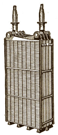
Fig. 38
Fig. 38
The proper conditions are established by providing a conducting circuit between the two elements, in which lamps, motors, or[124] other electrical devices are placed. As soon as this circuit is provided, the opportunity is given to the iron to receive the oxygen. This it does, and in so doing develops electrical energy.
The right conditions are created by setting up a circuit that connects the two elements, with lamps, motors, or[124] other electrical devices included. Once this circuit is established, the iron has the chance to take in oxygen. It does this and, in the process, generates electrical energy.
This energy is in the form of electric current which is then delivered by the battery on what is called the "discharge," and this current may be used for lighting lamps or for operating motors or other electrical devices.
This energy comes in the form of electric current, which the battery delivers during what's called the "discharge." This current can be used to power lighting lamps, operate motors, or run other electrical devices.
The battery is said to be discharging as long as the iron is receiving oxygen from the nickel oxide. As soon as it becomes iron oxide once more, the giving out of energy ceases and the battery is said to be "discharged," and must again be charged to obtain further work from it. Such a battery can be charged and discharged an indefinite number of times.
The battery is said to be discharging as long as the iron is receiving oxygen from the nickel oxide. Once it turns back into iron oxide, the release of energy stops, and the battery is considered "discharged," meaning it needs to be charged again to generate more energy. This type of battery can be charged and discharged an unlimited number of times.
This type of battery is very rugged, and its combinations are not self-destructive. It is very simple, as it provides chiefly for the movement of the oxygen back and forth; besides, it gives much more current for its[125] weight than the lead type of storage battery. (Fig. 38 shows the plates of a standard Edison cell removed from container.)
This type of battery is very durable, and its combinations are not self-destructive. It's quite straightforward, mainly allowing for the movement of oxygen back and forth; plus, it delivers significantly more power for its[125] weight compared to lead storage batteries. (Fig. 38 shows the plates of a standard Edison cell removed from the container.)
CONNECTING STORAGE BATTERIES
On the discharge, one cell of a lead storage battery gives an average of about 2 volts, and a cell of alkaline storage battery about 1.2 volts, no matter what its size or the number of plates may be. When there are more than two plates in one cell, all the positives in that cell are connected together by metallic strips or bands, and all negatives in the cell are connected together in a similar way.
On discharge, one cell of a lead-acid battery produces an average of about 2 volts, while a cell of an alkaline battery provides about 1.2 volts, regardless of its size or the number of plates. When there are more than two plates in a single cell, all the positive plates in that cell are linked together with metal strips or bands, and all the negative plates are connected in the same manner.
Although we cannot obtain more than the above-named electromotive force from one cell of either type of storage battery, we can obtain a greater ampère capacity by using large plates instead of small ones, or by using a larger number of small size.
Although we can't get more than the mentioned electromotive force from one cell of either type of storage battery, we can achieve a greater ampere capacity by using larger plates instead of smaller ones, or by using a larger number of smaller plates.
The same effects are produced by connecting the cells in series, or multiple, or multiple series, as we showed you in regard to primary batteries; and the storage batteries may be charged as well as discharged when connected in any one of these ways.
The same effects occur when the cells are connected in series, in parallel, or in a combination of both, just like we demonstrated with primary batteries. The storage batteries can be charged or discharged when connected in any of these configurations.
CHARGING CURRENT
The current which is used for charging must always be greater in pressure than that of the storage batteries which are being charged. If it is not, the storage batteries will be the stronger of the two and will overpower the charging current and so discharge themselves.
The current used for charging must always be stronger than the voltage of the storage batteries being charged. If it isn't, the storage batteries will be stronger and will drain themselves by overpowering the charging current.
X
CONCLUSION
CONCLUSION
We will now bring this little volume to a close, having given you a brief outline of the simplest rudiments of that wonderful power of nature, Electricity.
We will now wrap up this small book, having provided you with a brief overview of the basic fundamentals of that amazing natural force, Electricity.
We may compare this subject to a beautiful house the inside of which you would like to examine from top to bottom. We have opened the door for you; now walk in and examine everything. There may be a great many stairs to climb, but what you see and learn will repay for all the trouble.
We can think of this topic like a beautiful house that you want to explore from top to bottom. We’ve opened the door for you, so go ahead and look around. There might be a lot of stairs to climb, but what you discover will make it all worthwhile.
THE END
THE END
FOOTNOTES:
[2] The batteries we will now describe are for closed-circuit work only, and they are never used for open-circuit work. But there is a type of battery made that is available for either open or closed circuit operation. This is the Edison Primary Battery, which will be described later on.
[2] The batteries we’re going to talk about are designed for closed-circuit use only, and they are never used for open-circuit applications. However, there is a type of battery that can function in both open and closed circuit mode. This is the Edison Primary Battery, which will be explained later.
[3] Practically, there is always one more negative plate than positive plates in a regular storage-battery cell. Consequently, a standard cell always contains an odd number of plates.
[3] In practice, there is always one more negative plate than positive plates in a regular storage-battery cell. As a result, a standard cell always has an odd number of plates.
TRANSCRIBER'S NOTE
**Transcriber's Note**
—Plain print and punctuation errors fixed.
—Plain print and punctuation errors fixed.
Download ePUB
If you like this ebook, consider a donation!