This is a modern-English version of Motorcycle, Solo (Harley-Davidson Model WLA), originally written by United States. War Department.
It has been thoroughly updated, including changes to sentence structure, words, spelling,
and grammar—to ensure clarity for contemporary readers, while preserving the original spirit and nuance. If
you click on a paragraph, you will see the original text that we modified, and you can toggle between the two versions.
Scroll to the bottom of this page and you will find a free ePUB download link for this book.

| 1TM 9–879 | ||
|---|---|---|
| RESTRICTED | ||
| TECHNICAL MANUAL No. 9–879 |
⎫ ⎬ ⎭ |
DEPARTMENT OF DEFENSE Washington, October 18, 1943 |
Riding a motorcycle alone
(Harley-Davidson Model WLA)
Dissemination of restricted matter.—The information contained in restricted documents, and the essential characteristics of restricted materiel, may be given to any person known to be in the service of the United States, and to persons of undoubted loyalty and discretion who are cooperating in Government work, but will not be communicated to the public or to the press except by authorized military public relations agencies. (See also paragraph 18b, AR 380–5, 28 September 1942.)
Sharing of restricted information.—The information in restricted documents and the main features of restricted materials can be shared with anyone known to be serving the United States, as well as individuals who have proven loyalty and discretion and are involved in Government work. However, this information will not be made public or shared with the press except through authorized military public relations agencies. (See also paragraph 18b, AR 380–5, 28 September 1942.)
CONTENTS
| PART ONE—CAR OPERATING INSTRUCTIONS | ||||
|---|---|---|---|---|
| Paragraphs | Pages | |||
| Section | I | Introduction Intro |
1–2 | 3–6 |
| II | Description and tabulated data Description and data table |
3–4 | 7–8 | |
| III | Controls and operation Controls and operation |
5–13 | 9–19 | |
| IV | First echelon, preventive maintenance services First level, preventive maintenance services |
14–18 | 20–29 | |
| V | Lubrication Lube |
19–20 | 30–34 | |
| VI | Tools and equipment stowage on the vehicle Tools and equipment storage on the vehicle |
21–23 | 35–38 | |
| PART TWO—ORG MAINTENANCE | ||||
| Section | VII | Maintenance allocation Maintenance budget |
24–25 | 39–44 |
| VIII | Second echelon preventive maintenance services Second-level preventive maintenance services |
26 | 45–59 | |
| IX | Organization tools and equipment Organizational tools and equipment |
27 | 60 | |
| X | Trouble shooting Troubleshooting |
28–38 | 61–71 | |
| XI | Engine Engine |
39–44 | 72–77 | |
| XII | Engine—removal and installation Engine removal and installation |
45–46 | 78–84 | |
| XIII | Clutch Clutch (car part) |
47–52 | 85–95 | |
| XIV | Transmission Transmission |
53–58 | 96–104 2 | |
| XV | Chains and sprockets Chains and gears |
59–66 | 105–114 | |
| XVI | Fuel system Fuel system |
67–74 | 115–121 | |
| XVII | Intake and exhaust system Intake and exhaust systems |
75–81 | 122–128 | |
| XVIII | Ignition system Ignition system |
82–89 | 129–141 | |
| XIX | Generating system Generating system |
90–95 | 142–148 | |
| XX | Brake system Braking system |
96–97 | 149–153 | |
| XXI | Steering control Steering control |
98–101 | 154–166 | |
| XXII | Sheet metal and equipment Metal sheets and tools |
102–111 | 167–180 | |
| XXIII | Battery, lighting system, horn Battery, lights, horn |
112–118 | 181–190 | |
| XXIV | Instrument panel Dashboard |
119–121 | 191–192 | |
| XXV | Tires, wheels, and hubs Tires, rims, and hubs |
122–127 | 193–199 | |
| References | 200 | |||
| Index | 201 | |||
Part One—Operating Instructions
Section I
INTRODUCTION
1. SCOPE.
a. This technical manual2 is published for the information and guidance of the using arm personnel charged with the operation, maintenance, and minor repair of this materiel.
a. This technical manual2 is published to inform and guide the personnel responsible for operating, maintaining, and making minor repairs to this equipment.
b. In addition to a description of the Harley‐Davidson motorcycle, this manual contains technical information required for the identification, use, and care of the materiel. The manual is divided into two parts. Part One, section I through section VI, gives vehicle operating instructions. Part Two, section VII through section XXV, gives vehicle maintenance instructions to using arm personnel charged with the responsibility of doing maintenance work within their jurisdiction.
b. In addition to a description of the Harley-Davidson motorcycle, this manual includes the technical information needed to identify, use, and care for the equipment. The manual is divided into two parts. Part One, sections I through VI, provides vehicle operating instructions. Part Two, sections VII through XXV, offers vehicle maintenance instructions for the personnel responsible for maintenance work in their area.
c. In all cases where the nature of the repair, modifications, or adjustment is beyond the scope or facilities of the unit, the responsible ordnance service should be informed so that trained personnel with suitable tools and equipment may be provided, or proper instructions issued.
c. In all instances where the type of repair, modifications, or adjustments exceed the capabilities or resources of the unit, the responsible ordnance service should be notified so that qualified personnel with the right tools and equipment can be provided, or appropriate instructions can be given.
2. SUPERSESSION OF QUARTERMASTER MANUALS.
a. This technical manual, together with TM 9–1879, supersedes and replaces the following Quartermaster Corps publications:
a. This technical manual, along with TM 9–1879, takes the place of and replaces the following Quartermaster Corps publications:
(1) TM 10–1175—Maintenance manual, motorcycle, solo, Harley‐Davidson (Model 42–WLA), 11 September 1941.
(1) TM 10–1175—Maintenance manual, motorcycle, solo, Harley-Davidson (Model 42-WLA), September 11, 1941.
(2) TM 10–1177—Maintenance manual, motorcycle, solo, Harley‐Davidson (Models 1940–41–42), 11 September 1941.
(2) TM 10–1177—Maintenance manual, motorcycle, solo, Harley-Davidson (Models 1940–41–42), September 11, 1941.
(3) TM 10–1331—Maintenance manual, motorcycle, chain drive Harley‐Davidson (Model 42 WLA, solo).
(3) TM 10–1331—Maintenance manual, motorcycle, chain drive Harley-Davidson (Model 42 WLA, solo).
(4) TM 10–1359—Instruction folder (45–A) motorcycles, solo, Harley‐Davidson (Model 1941 WLA 45), 25 November 1941.
(4) TM 10–1359—Instruction folder (45–A) motorcycles, solo, Harley-Davidson (Model 1941 WLA 45), November 25, 1941.
(5) TM 10–1361—Instruction folder (45–B) motorcycle, solo, Harley‐Davidson (Model 1941 WLA 45), 25 November 1941.
(5) TM 10–1361—Instruction folder (45–B) motorcycle, solo, Harley-Davidson (Model 1941 WLA 45), November 25, 1941.


RA PD 315709
Figure 2—Left Side View of Motorcycle
RA PD 315709
Figure 2—Left Side View of Motorcycle

RA PD 315710
Figure 3—Right Side View of Motorcycle
RA PD 315710
Figure 3—Right Side View of Motorcycle
2 To provide operating instructions with the materiel, this technical manual has been published in advance of complete technical review. Any errors or omissions will be corrected by changes or, if extensive, by an early revision.
2 This technical manual has been released early to provide operating instructions for the equipment, before a full technical review is completed. Any mistakes or missing information will be fixed through updates, or if significant, in an upcoming revision.
Section 2
DESCRIPTION AND TABULATED DATA
3. DESCRIPTION (figs. 1, 2, and 3).
a. This 2‐cylinder solo motorcycle is powered by a V‐type, air‐cooled gasoline engine, operating on conventional 4‐stroke, 4‐cycle principles. Air‐cooled engines rely upon movement of air over cylinder and head radiating fins, and upon circulation of oil for dissipation of excessive heat. Motorcycle engines, therefore, under no conditions should be operated for more than 1 minute when motorcycle is not in motion.
a. This 2-cylinder solo motorcycle has a V-type, air-cooled gasoline engine that runs on standard 4-stroke, 4-cycle principles. Air-cooled engines depend on the airflow over the cylinder and head cooling fins, as well as oil circulation to get rid of excess heat. Therefore, motorcycle engines should never be run for more than 1 minute when the motorcycle isn't moving.
4. DATA.
| a. Vehicle Specifications. | |
| Type of engine | 2‐cylinder, V‐type L‐head, air‐cooled |
| Cylinder bore | 2¾ in. |
| Stroke | 313⁄16 in. |
Engine number (serial) left side engine base, below front cylinder. Engine number (serial) is located on the left side of the engine base, below the front cylinder. |
|
| Wheelbase | 4 ft 11½ in. |
| Length over‐all | 7 ft 4 in. |
| Width over‐all (handle bars) | 3 ft 5 in. |
| Wheel size | 18 in. |
| Tire size | 4.00 × 18 in. |
| Tire type | Drop center |
Weight of vehicle (without rider or armament) Weight of vehicle (without rider or weapons) | 540 lb. |
| Ground clearance (skid plate) | 4 in. |
| Kind and grade of fuel | Gasoline: 72 octane or higher |
| High gear ratio | 4.59:1 |
| Engine sprocket | 31‐tooth |
| Countershaft sprocket | 17‐tooth |
| Rear wheel sprocket | 41‐tooth |
| b. Performance. | |
| Maximum allowable speed | 65 mph |
| Miles per gallon (hard surface) | 35 |
| Cruising range (without refill) | 100 miles 8 |
| Fording depth (carburetor) | 18 in. |
| c. Capacities. | |
| Fuel capacity (left tank) | 33⁄8 U.S. gal |
| Oil tank capacity (right tank) | 11⁄8 U.S. gal |
| Transmission capacity | ¾ pt |
Section 3
Controls and Operation
| Below is a short piece of text (5 words or fewer). Modernize it into contemporary English if there's enough context, but do not add or omit any information. If context is insufficient, return it unchanged. Do not add commentary, and do not modify any placeholders. If you see placeholders of the form __A_TAG_PLACEHOLDER_x__, you must keep them exactly as-is so they can be replaced with links. | |
|---|---|
| Controls | 5 |
| Engine prestarting instructions | 6 |
| Starting the engine | 7 |
| Stopping the engine | 8 |
| Operation of vehicle | 9 |
| Driving precautions | 10 |
| Stopping and parking vehicle | 11 |
| Towing vehicle to start engine | 12 |
| Running‐in new engine (or vehicle) | 13 |

5. CONTROLS (fig. 4).
a. Controls are peculiar to the motorcycle. The rider must become thoroughly familiar with the location and use of all control devices before attempting to operate vehicle.
a. The controls are specific to the motorcycle. The rider needs to be fully aware of the location and use of all control devices before trying to operate the vehicle.
b. Gasoline Valve (figs. 5 and 6). Gasoline valve is located in left tank, forward. Valve is closed by turning to the right, finger tight. Turning to left opens valve. Valve is in normal operating position10 when turned to left, with valve head down. Lifting valve head releases emergency supply of fuel (3 quarts).
b. Gasoline Valve (figs. 5 and 6). The gasoline valve is located in the left tank, towards the front. To close the valve, turn it to the right until it's snug. Turning it to the left opens the valve. The valve is in its normal operating position10 when turned to the left, with the valve head facing down. Lifting the valve head releases an emergency supply of fuel (3 quarts).


c. Throttle. The throttle is controlled by right handle bar grip. Turning grip inward opens throttle, turning it outward closes throttle.
c. Throttle. The throttle is controlled by the grip on the right handlebar. Turning the grip inward opens the throttle, while turning it outward closes it.
d. Spark. Spark is controlled by left handle bar grip. Turning grip inward advances spark, turning it outward retards spark.
d. Spark. The spark is controlled by the left handlebar grip. Turning the grip inward increases the spark, while turning it outward decreases the spark.
e. Clutch (fig. 7). Clutch is operated by left foot (rocker‐type) pedal, connecting with steel cable, which actuates clutch release lever. Pedal is located on left side of motorcycle above footboard. Forward downward (toe) position of pedal engages clutch. Rear downward (heel) position of pedal disengages clutch. Foot pedal provided with friction device to retain it in either engaged or disengaged position.
e. Clutch (fig. 7). The clutch is controlled by a left foot pedal (rocker-type) that connects to a steel cable, which activates the clutch release lever. The pedal is positioned on the left side of the motorcycle above the footboard. Pressing the pedal forward and down (with your toe) engages the clutch. Pressing it backward and down (with your heel) disengages the clutch. The foot pedal is equipped with a friction device to hold it in either the engaged or disengaged position.


RA PD 310205
Figure 8—Gear Shifter Lever Positions
RA PD 310205
Figure 8—Gear Shifter Lever Positions
f. Service Brake (Rear Wheel). Foot pedal is located on right side of motorcycle at forward end of footboard.
f. Service Brake (Rear Wheel). The foot pedal is located on the right side of the motorcycle at the front end of the footboard.
g. Auxiliary Brake (Front Wheel). Auxiliary brake is operated by hand lever located on left handle bar. It is used in conjunction with service brake, as an emergency brake, or for holding vehicle while starting engine on grade. CAUTION: Brake is to be applied lightly and cautiously on wet and slippery roads.
g. Auxiliary Brake (Front Wheel). The auxiliary brake is operated by a hand lever located on the left handlebar. It is used alongside the service brake, as an emergency brake, or to hold the vehicle while starting the engine on an incline. CAUTION: Apply the brake lightly and cautiously on wet and slippery roads.
h. Gear Shifter (fig. 8). Shifter lever is located on left tank, forward position, and operates within a guide. Shifter lever guide is notched for positive location of gears and each position is identified, front to rear: “1”—low gear; “N”—neutral; “2”—second gear; “3”—direct high gear.
h. Gear Shifter (fig. 8). The shifter lever is located on the left tank, at the front, and moves within a guide. The shifter lever guide has notches for a clear indication of the gears, and each position is labeled from front to back: “1”—low gear; “N”—neutral; “2”—second gear; “3”—direct high gear.

RA PD 310206
Figure 9—Carburetor Choke Lever Positions
RA PD 310206
Figure 9—Carburetor Choke Lever Positions
i. Steering Damper. Steering damper is an adjustable friction device to damper turning action of forks, steady front wheel, and prevent wobble in rough terrain or at high speeds, and is located on top of steering head in center of handle bars. Move handle to right to apply desired friction.
i. Steering Damper. A steering damper is an adjustable friction device that dampens the turning action of the forks, stabilizes the front wheel, and prevents wobbling on rough terrain or at high speeds. It is located on top of the steering head in the center of the handlebars. Move the handle to the right to apply the desired friction.
j. Foot Starter Crank (fig. 1). The foot starter crank is located on right side of motorcycle. Gear shifter lever must be in neutral position, and clutch foot pedal in forward engaged position, before using foot starter crank. Starter crank normally is in upward position. Straddle motorcycle, place right foot on starter crank, and shift weight of body for forceful downward crank operation to start engine.
j. Foot Starter Crank (fig. 1). The foot starter crank is located on the right side of the motorcycle. The gear shift lever must be in the neutral position, and the clutch pedal must be fully engaged before using the foot starter crank. The starter crank is usually in an upward position. Straddle the motorcycle, place your right foot on the starter crank, and shift your body weight downwards with force to start the engine.
k. Ignition and Light Switch. Earlier models are provided with switch lock, later models are nonlocking. Switch is off in straight‐forward position. First position to right is for engine ignition only.13 Second position to right is for ignition and blackout lights. To use vehicle service lights, depress button to turn switch to third right position.
k. Ignition and Light Switch. Earlier models have a switch lock, while later models do not. The switch is off when it's in the straightforward position. The first position to the right is for engine ignition only.13 The second position to the right is for ignition and blackout lights. To use the vehicle service lights, press the button to turn the switch to the third position on the right.
l. Instrument Panel Signal Lights. Instead of an ammeter and oil pressure gage, signal lights indicate generator charging, and engine oil pressure.
l. Instrument Panel Signal Lights. Instead of an ammeter and oil pressure gauge, signal lights show when the generator is charging and when the engine oil pressure is normal.
(1) Green light is located on left side of instrument panel. When engine is running, and light is out, it indicates generator is charging.
(1) The green light is on the left side of the instrument panel. When the engine is running and the light is off, it means the generator is charging.
(2) Red light is located on right side of instrument panel. When engine is running, and light is out, it indicates engine oil is circulating.
(2) The red light is on the right side of the instrument panel. When the engine is running and the light is off, it means the engine oil is circulating.
m. Carburetor Choke (fig. 9). Choke lever is in full prime position when all the way up, and in normal running position when all the way down.
m. Carburetor Choke (fig. 9). The choke lever is fully primed when it's all the way up and in the normal running position when it's all the way down.
6. ENGINE PRESTARTING INSTRUCTIONS.
a. Before the engine is started, perform the Before‐operation Service outlined in paragraph 15. Special care must be taken during starting and warming‐up period to avoid unnecessary engine wear.
a. Before starting the engine, complete the Before-operation Service described in paragraph 15. Take extra care during the starting and warm-up period to prevent unnecessary engine wear.
b. The rider must acquire correct motorcycle engine starting habits, and learn to do the job the quickest, easiest, and most dependable way. The following pointers will be helpful to the beginner as well as to a seasoned rider:
b. The rider needs to develop good habits for starting the motorcycle engine and learn to do it in the quickest, easiest, and most reliable way. The following tips will be useful for both beginners and experienced riders:
(1) Mount (straddle) motorcycle to obtain firm grip on handle bars.
(1) Get on the motorcycle and grab the handlebars securely.
(2) Leave side stand (jiffy stand) outward to support vehicle while operating foot starter crank with right foot.
(2) Keep the side stand (jiffy stand) extended to support the vehicle while using the foot starter crank with your right foot.
(3) Engine starting will be benefited by use of front wheel, hand‐operated brake, to prevent vehicle from rolling or shifting during starting kicks. This is especially helpful if vehicle is parked on an incline or on soft, uneven surface.
(3) Starting the engine will be easier with the use of the front wheel, hand-operated brake, to keep the vehicle from rolling or moving during starting attempts. This is particularly useful if the vehicle is parked on a slope or on a soft, uneven surface.
c. The procedure outlined below is preparatory to starting either cold, warm, or hot engine:
c. The procedure described below is a preliminary step for starting a cold, warm, or hot engine:
(1) Place gear shifter lever in “N” (neutral) position (fig. 8).
(1) Put the gear shifter lever in the “N” (neutral) position (fig. 8).
(2) See that gasoline shut‐off valve is open (fig. 5).
(2) Make sure the gasoline shut-off valve is open (fig. 5).
(3) Engage clutch (fig. 7).
Engage the clutch (__A_TAG_PLACEHOLDER_0__).
(4) Spark control (left) grip must be turned inward to fully advanced position, or nearly so.
(4) The spark control (left) grip needs to be turned inward to its fully advanced position, or close to it.
(5) Foot starter crank may travel ½ way downward before starting engine. See that a full vigorous starter stroke is used. A vigorous kick, using a full swing (not a jab) of right leg and hip, is correct engine starting practice.
(5) The foot starter crank may need to travel halfway down before the engine starts. Make sure to use a strong, full starter stroke. A powerful kick, using a full swing (not a quick jab) of your right leg and hip, is the right way to start the engine.
7. STARTING THE ENGINE.
a. Procedure for starting cold, warm, or hot motorcycle engines differs. Therefore, following instructions are used with paragraph 6 c to cover correct procedure in all three cases.
a. The process for starting cold, warm, or hot motorcycle engines varies. Therefore, the following instructions are provided in paragraph 6 c to cover the correct procedure for all three situations.
b. Starting Cold Engine. When vehicle has not been operated for some time, and engine is normally cold, follow progressive procedure for easiest starting.
b. Starting Cold Engine. When the vehicle hasn't been used for a while and the engine is cold, follow the step-by-step process for the easiest starting.
(1) Set carburetor choke lever in full upward (closed) position.
(1) Move the carburetor choke lever all the way up (closed position).
(2) Open throttle wide by turning right grip inward as far as it will go.
(2) Open the throttle fully by rotating the right grip inward as far as it will go.
(3) Prime cylinders by operating foot starter crank one or two strokes.
(3) Prime the cylinders by turning the foot starter crank one or two times.
(4) Set carburetor choke lever in ¼ to ½ closed position for mild weather starting: ¾ closed (or leave fully choked) for extremely cold weather starting. CAUTION: It is only in extremely cold weather that engine may start best with choke fully closed, and even then it will have to be moved from this position immediately after engine is started.
(4) Set the carburetor choke lever to a position between ¼ and ½ closed for starting in mild weather: ¾ closed (or leave it fully choked) for starting in extremely cold weather. CAUTION: Only in extremely cold weather might the engine start best with the choke fully closed, and even then, it must be moved from that position immediately after the engine starts.
(5) Set throttle (right) grip to slightly open position.
(5) Adjust the throttle (right) grip to a slightly open position.
(6) Turn ignition switch on, first right position.
(6) Turn the ignition switch on to the first right position.
(7) Start engine with vigorous strokes of foot starter crank.
(7) Start the engine with strong kicks on the foot starter crank.
(8) When engine starts, set throttle for moderate idling speed for warming up, or until ready to set vehicle in motion. Do not race engine unnecessarily.
(8) When the engine starts, adjust the throttle to a moderate idling speed to warm it up, or until you're ready to start driving. Don't rev the engine unnecessarily.
(9) After engine warms up, and misfires due to an overrich mixture, gradually move choke lever downward. After engine has thoroughly warmed up, move choke lever to fully open (downward) position.
(9) After the engine warms up and misfires because of a too-rich mixture, slowly move the choke lever downward. Once the engine has completely warmed up, move the choke lever to the fully open (downward) position.
c. Starting Warm Engine. Following instructions apply to engine when halfway between hot and cold. With engine in this condition, carburetor choking must be handled cautiously.
c. Starting Warm Engine. The following instructions apply to the engine when it’s halfway between hot and cold. With the engine in this condition, carburetor choking needs to be handled carefully.
(1) Lift choke lever to first upward position from normal (¼ closed).
(1) Raise the choke lever to the first upward position from normal (¼ closed).
(2) Set throttle (right) grip to fully closed (outward) position.
(2) Turn the throttle (right) grip to the fully closed (outward) position.
(3) Operate foot starter crank one or two strokes.
(3) Use the foot starter crank for one or two strokes.
(4) Set throttle grip to between ¼ and 1⁄3 open position.
(4) Set the throttle grip to between ¼ and 1⁄3 open position.
(5) Turn ignition switch on.
Turn on ignition switch.
(6) Start engine with vigorous strokes of foot starter crank.
(6) Start the engine by giving the foot starter crank a strong kick.
(7) Soon after engine starts, choke lever must be moved to fully open (downward) position.
(7) Soon after the engine starts, the choke lever must be moved to the fully open (downward) position.
(8) Turn throttle grip to control idling speed of engine.
(8) Turn the throttle grip to control the engine's idling speed.
d. Starting Hot Engine. If engine has been shut off for only a brief period and is near normal operating temperature, it is not necessary to use carburetor choke lever. With some engines, depending upon carburetor condition and adjustment, hot starting is easier and more dependable if foot starter crank is operated one stroke before turning ignition switch on.
d. Starting Hot Engine. If the engine has been turned off for just a short time and is close to its normal operating temperature, you don’t need to use the carburetor choke lever. For some engines, depending on the condition and adjustment of the carburetor, hot starting is easier and more reliable if you operate the foot starter crank once before turning on the ignition switch.
(1) Close throttle grip by turning fully outward.
(1) Fully open the throttle grip by turning it all the way outward.
(2) Turn ignition switch on.
Turn on ignition switch.
(3) Operate foot starter crank to start engine.
(3) Use the foot starter crank to start the engine.
(4) When hot engine does not start readily after two or three strokes of the foot starter crank, it is usually due to an overrich (flooded) condition, and the proper procedure then is to open throttle wide so that more air can enter: close throttle quickly after engine starts. CAUTION: After engine has warmed up to a normal operating temperature, do not allow engine to stand idling for longer than a 1 minute interval.
(4) If your hot engine doesn’t start easily after turning the foot starter crank two or three times, it’s usually because it’s flooded. The right thing to do is to open the throttle all the way to let in more air; close the throttle quickly once the engine starts. CAUTION: Once the engine has warmed up to its normal operating temperature, don’t let it idle for more than 1 minute at a time.
e. Starting Engine with Dead Battery. See paragraph 12.
e. Starting Engine with Dead Battery. See paragraph 12.
f. Behavior of Instrument Panel Signal Lights. Function of generator (green) signal light depends upon action of cut‐out relay; engine oil pressure (red) signal light depends upon action of oil feed pump. Rider must, therefore, thoroughly understand operating characteristics of both signal lights to judge condition of generator‐battery circuit and pressure in engine oil circulating system.
f. Behavior of Instrument Panel Signal Lights. The function of the generator (green) signal light relies on the cut-out relay's actions; the engine oil pressure (red) signal light depends on the oil feed pump's actions. Therefore, the rider needs to fully understand how both signal lights operate to assess the condition of the generator-battery circuit and the pressure in the engine's oil circulating system.
(1) When ignition light switch is turned to first (right) position, preparatory to starting engine, both green and red signal lights should go on. CAUTION: When switch is turned on, immediately after engine has been primed by cranking, red (oil pressure) signal light may not light at once, but will light after a few seconds, due to oil pressure built up by cranking, and is most likely to be noticed in cold weather.
(1) When the ignition light switch is turned to the first (right) position to prepare for starting the engine, both the green and red indicator lights should turn on. CAUTION: When the switch is turned on right after the engine has been primed by cranking, the red (oil pressure) indicator light may not turn on immediately, but will light up after a few seconds due to oil pressure building up from cranking, and this is more likely to be noticed in cold weather.
(2) With engine started and running at medium idling speed, both signal lights should go off. CAUTION: Should oil pressure (red) signal light fail to go off at speeds above idling, conditions must be brought to attention of unit mechanic.
(2) With the engine started and running at a moderate idle speed, both signal lights should turn off. CAUTION: If the oil pressure (red) signal light does not turn off at speeds above idle, the conditions must be reported to the unit mechanic.
(3) At slow idle speed, or under approximately 20 miles per hour road speed (in high gear), generator (green) signal light will normally flash on and off, because at that speed generator voltage output is very low and unsteady. CAUTION: Should generator (green) signal light fail to go off at speed above approximately 20 miles per hour, generator is either not charging at all, or its current output is not up to normal, and generator should be given attention at once.
(3) At a slow idle or under about 20 miles per hour (in high gear), the generator (green) signal light will usually flash on and off because the generator's voltage output is very low and unstable at that speed. CAUTION: If the generator (green) signal light does not turn off at speeds above approximately 20 miles per hour, the generator is either not charging at all, or its current output is below normal, and it should be checked immediately.
8. STOPPING THE ENGINE.
a. Stop engine only by turning ignition and light switch to off (straight‐ahead) position, to prevent discharge of battery through spark coil primary circuit.
a. Turn off the engine by switching the ignition and light switch to the off (straight-ahead) position to avoid draining the battery through the spark coil's primary circuit.
9. OPERATION OF VEHICLE.
a. Starting on Level Ground. The engine having been warmed up and checked for satisfactory operation, the vehicle (with operator in riding position) is put in motion as follows:
a. Starting on Level Ground. Once the engine is warmed up and has been checked for proper functioning, the vehicle (with the operator in the riding position) is set in motion like this:
(1) Transfer body weight to right leg.
(1) Shift your weight to your right leg.
(2) Fold back side stand (jiffy stand).
(2) Fold back the side stand (kickstand).
(3) Disengage clutch by depressing clutch foot pedal with heel of left foot.
(3) Release the clutch by pressing down on the clutch pedal with the heel of your left foot.
(4) Shift gear shifter lever into “1” (low) gear position.
(4) Move the gear shifter lever into the “1” (low) gear position.
(5) Slowly engage clutch by depressing clutch foot pedal with toe of left foot.
(5) Gradually engage the clutch by pressing down the clutch pedal with the toe of your left foot.
(6) When clutch starts to “take hold,” open throttle sufficiently to maintain engine speed.
(6) When the clutch starts to grab, open the throttle enough to keep the engine speed.
(7) Accelerate gradually to between 12 and 15 miles per hour in low gear.
(7) Gradually speed up to between 12 and 15 miles per hour in low gear.
(8) Close throttle quickly.
Close throttle fast.
(9) Disengage clutch.
Disengage the clutch.
(10) Shift through “N” (neutral) position into “2” (second) gear.
(10) Move from the “N” (neutral) position to “2” (second) gear.
(11) Reengage clutch and accelerate to about 25 miles per hour.
(11) Release the clutch and speed up to around 25 miles per hour.
(12) Close throttle quickly.
Quickly close the throttle.
(13) Disengage clutch.
Disengage the clutch.
(14) Shift into “3” (high) gear.
(14) Shift into “3” (high) gear.
(15) Reengage clutch and accelerate to desired speed.
(15) Reengage the clutch and speed up to your desired speed.
b. Starting on Uneven or Soft Ground.
b. Starting on Uneven or Soft Ground.
(1) If standing on an incline or in loose, heavy ground, more engine power will be required to start vehicle without stalling engine.
(1) If you're on a slope or in loose, heavy soil, you'll need more engine power to start the vehicle without stalling.
(2) It may be necessary to keep vehicle from rolling by keeping pressure on front brake hand lever. Brake pressure is released after vehicle starts in forward motion.
(2) It might be necessary to prevent the vehicle from rolling by applying pressure to the front brake hand lever. Brake pressure is released once the vehicle starts moving forward.
(3) Open throttle and engage clutch at same time to provide power needed for starting, without racing engine unnecessarily.
(3) Open the throttle and engage the clutch at the same time to provide the power needed for starting, without revving the engine unnecessarily.
(4) Motorcycle starts should be made without excessive application of power, with consequent unnecessary spinning of rear wheel.
(4) Motorcycle starts should be done without putting too much power down, which would cause the rear wheel to spin unnecessarily.
10. DRIVING PRECAUTIONS.
a. Practice will enable a rider to judge at what rate of speed the motorcycle should be moving before he shifts from a lower to higher17 gear, and engine should never be permitted to labor unduly, when a shift of gears, higher to lower, would improve operation.
a. Practicing will help a rider determine the appropriate speed at which to shift from a lower to a higher17 gear, and the engine should never be allowed to strain excessively when shifting from higher to lower would enhance performance.
(1) Operator must not look down at gear shifter when shifting gears, but keep his eyes on the road ahead. Do not ride the clutch. The operator’s foot should rest on clutch foot pedal only when he is operating it. When shifting gears, disengage clutch fully to avoid gear damage and shifting difficulties. CAUTION: Many transmissions are ruined through failure to disengage clutch fully when shifting gears.
(1) The operator must not look down at the gear shifter while changing gears but should keep their eyes on the road ahead. Do not ride the clutch. The operator's foot should only rest on the clutch pedal when operating it. When shifting gears, fully disengage the clutch to avoid damaging the gears and having trouble shifting. CAUTION: Many transmissions are ruined because the clutch isn't fully disengaged when shifting gears.
b. Braking. Rear wheel service brake must be in such condition that medium‐hard application will cause rear wheel to lock. Application of service brake should be gradual, with just enough force to accomplish desired result.
b. Braking. The rear wheel service brake must be in a condition where a medium-hard application will cause the rear wheel to lock. The application of the service brake should be gradual, using just enough force to achieve the desired result.
(1) Auxiliary front wheel brake, when used in conjunction with service brake, must be applied with caution, especially on wet, muddy, or slippery roads.
(1) The auxiliary front wheel brake, when used along with the service brake, should be applied carefully, especially on wet, muddy, or slippery roads.
(2) After passing through water, the brakes should be set slightly, and the vehicle operated for a short distance, until sufficient heat has been generated to dry the brakes.
(2) After going through water, the brakes should be lightly engaged, and the vehicle should be driven a short distance until enough heat is produced to dry the brakes.
c. Avoid Low Gear Operation. Always operate vehicle in highest gear possible, consistent with tactical situation, speed required, power required, and kind and nature of road substance, to prevent overheating of engine.
c. Avoid Low Gear Operation. Always drive the vehicle in the highest gear possible, based on the tactical situation, necessary speed, required power, and type and condition of the road surface, to avoid overheating the engine.
d. High Speed Tips. Only experienced riders should indulge in high‐speed riding. A motorcycle operated for long distances at high speed must be given closer than ordinary attention to avoid serious engine overheating with consequent damage. For better motorcycle service, apply the following suggestions:
d. High Speed Tips. Only experienced riders should engage in high-speed riding. A motorcycle that's used for long distances at high speeds requires more careful attention to prevent serious engine overheating and potential damage. For better motorcycle performance, consider the following suggestions:
(1) Develop habit of frequently snapping throttle shut for an instant when running at high speed. This draws additional lubrication to piston and cylinder and assists in cooling engine.
(1) Make it a habit to quickly close the throttle for a moment when running at high speed. This brings extra lubrication to the piston and cylinder and helps cool the engine.
(2) In cool weather, operate engine slowly until it is thoroughly warmed up, to avoid damage to pistons, rings, cylinders, and other parts before oil is warm enough to circulate freely.
(2) In cool weather, run the engine slowly until it's properly warmed up to prevent damage to the pistons, rings, cylinders, and other parts before the oil gets warm enough to flow freely.
(3) If handle bar windshield and leg shields are used, engine is more likely to overheat with continued high‐speed riding. Watch this carefully.
(3) If you use a handlebar windshield and leg shields, the engine is more likely to overheat during prolonged high-speed riding. Keep an eye on this.
(4) Adjust “steering damper” for best control of motorcycle consistent with riding speed and condition and nature of road.
(4) Adjust the “steering damper” for optimal motorcycle control based on your riding speed, the conditions, and the type of road.
11. STOPPING AND PARKING VEHICLE.
a. Stopping Vehicle. Rider will make a “restart” easier and quicker if he will apply the following instructions upon stopping vehicle:
a. Stopping Vehicle. The rider will make a “restart” easier and quicker if they follow these instructions when stopping the vehicle:
(1) Close throttle.
Cut throttle.
(2) Disengage clutch.
Disengage the clutch.
(3) Apply brake (or brakes) to slow vehicle without sliding rear tire.
(3) Use the brake(s) to slow down the vehicle without causing the rear tire to skid.
(4) Just before coming to a complete stop, shift into “N” (neutral) position and engage clutch. CAUTION: If immediate restart is to be made, shift into “1” (low) gear and allow clutch foot pedal to remain in disengaged position. (Rider will be mounted on motorcycle with engine running.)
(4) Just before coming to a complete stop, shift into “N” (neutral) position and engage the clutch. CAUTION: If you need to restart right away, shift into “1” (low) gear and keep the clutch pedal in the disengaged position. (The rider will be sitting on the motorcycle with the engine running.)
(5) Continue brake application to complete stop.
(5) Keep applying the brakes until you come to a complete stop.
(6) After vehicle slows to point where it can no longer be balanced by steering, place left foot on ground to maintain balance until right foot can be removed from brake operating pedal. CAUTION: Do not idle engine longer than 1 minute.
(6) Once the vehicle slows down to the point where you can't balance it by steering anymore, put your left foot on the ground to stay balanced until you can take your right foot off the brake pedal. CAUTION: Don't let the engine run for more than 1 minute.
(7) Stop engine by turning ignition switch off.
(7) Turn off the ignition switch to stop the engine.
b. Parking Vehicle.
b. Parking a Vehicle.
(1) Lean motorcycle on side (jiffy) stand.
(1) Lean the motorcycle on the side (jiffy) stand.
(2) Shift into “1” (low) gear.
(2) Shift into “1” (low) gear.
(3) Engage clutch so vehicle cannot roll.
(3) Engage the clutch so the vehicle won't roll.
(4) Shut off gasoline supply by turning valve (to right) finger‐tight against its seat.
(4) Turn off the gasoline supply by turning the valve (to the right) until it's tight against its seat.
12. TOWING VEHICLE TO START ENGINE.
a. In emergencies when engine cannot be started with foot starter crank, it can be started by towing the motorcycle.
a. In emergencies when the engine can't be started with the foot starter crank, it can be started by towing the motorcycle.
(1) Set gear shifter lever in “2” (second) gear position.
(1) Set the gear shift lever to the “2” (second) gear position.
(2) Disengage clutch.
Disengage the clutch.
(3) Choke carburetor.
Choke the carburetor.
(4) Turn ignition switch on.
Turn on the ignition switch.
(5) After momentum of the towed motorcycle reaches between 10 and 15 miles per hour, engage clutch, and continue procedure until engine starts.
(5) Once the towed motorcycle reaches a speed of 10 to 15 miles per hour, pull in the clutch and keep going with the procedure until the engine starts.
b. Engine Starting with Dead Battery. Emergency engine starting with dead battery can be effected by making use of freshly charged battery, or by towing as outlined above. If vehicle with dead battery is to be towed for engine starting, proceed as follows:
b. Engine Starting with Dead Battery. You can start an engine with a dead battery by using a fully charged battery or by towing, as described above. If you need to tow a vehicle with a dead battery to start the engine, follow these steps:
(1) Disconnect battery negative wire from ground on right side of motorcycle.
(1) Disconnect the negative battery wire from the ground on the right side of the motorcycle.
(2) Tow motorcycle for engine starting.
(2) Tow a motorcycle to start the engine.
(3) After engine is started, reconnect battery ground wire to frame to prevent damage to electrical system.
(3) Once the engine is started, reconnect the battery ground wire to the frame to avoid damaging the electrical system.
13. RUNNING‐IN NEW ENGINE (OR VEHICLE).
a. A new motorcycle engine or newly overhauled engine must be given proper “break‐in” consideration for at least the first 1,000 to 1,200 miles of service. Failure to do this may result in damage that will put engine out of active service within a short period of time.
a. A new motorcycle engine or a recently overhauled engine needs to be properly "broken in" during the first 1,000 to 1,200 miles of use. Not doing this could lead to damage that might take the engine out of commission in a short amount of time.
b. At the first 250 miles, check front and rear drive chains to make sure they are receiving required amount of oil for ample lubrication. If necessary, have chain oilers adjusted by unit mechanic. Drive chains must be inspected for correct adjustment, and be given attention by unit mechanic as needed.
b. After the first 250 miles, check the front and rear drive chains to ensure they're getting enough oil for proper lubrication. If needed, have the chain oilers adjusted by the unit mechanic. The drive chains should also be checked for the correct adjustment and attended to by the unit mechanic as necessary.
c. At first 500 miles, drain oil tank and refill with fresh oil. Check front and rear chains (step b above). Thereafter, follow instructions in Maintenance Operation section.
c. After the first 500 miles, drain the oil tank and refill it with fresh oil. Check the front and rear chains (step b above). From then on, follow the instructions in the Maintenance Operation section.
d. After a new motorcycle has been run 500 to 1,000 miles it needs to be thoroughly checked over and any loose screws and nuts tightened. Particular attention must be given engine and transmission mounting bolts and nuts, and to rear wheel mounting socket screws.
d. After a new motorcycle has been ridden for 500 to 1,000 miles, it needs to be thoroughly inspected and any loose screws and nuts tightened. Special attention should be paid to the engine and transmission mounting bolts and nuts, as well as the rear wheel mounting socket screws.
e. Following pointers must be observed when running‐in new engine or newly overhauled engine:
e. The following guidelines should be followed when breaking in a new engine or a recently overhauled engine:
(1) Do not exceed 30 miles per hour during first 100 miles.
(1) Don't go over 30 miles per hour for the first 100 miles.
(2) Do not exceed 35 miles per hour during next 200 miles.
(2) Don’t go over 35 miles per hour for the next 200 miles.
(3) Do not exceed 40 miles per hour during next 400 miles.
(3) Do not go over 40 miles per hour for the next 400 miles.
(4) Do not exceed 50 miles per hour during next 500 miles.
(4) Don't go over 50 miles per hour for the next 500 miles.
(5) Avoid use of low gears during break‐in operation as much as possible.
(5) Try to avoid using low gears during the break-in period whenever you can.
Section 4
First Echelon Maintenance Services
| Please provide the short piece of text you would like me to modernize. | |
|---|---|
| Purpose | 14 |
| Before‐operation service | 15 |
| During‐operation service | 16 |
| At‐halt service | 17 |
| After‐operation and weekly service | 18 |
14. PURPOSE.
a. To insure mechanical efficiency it is necessary that the vehicle be systematically inspected at intervals each day it is operated and weekly, so that defects may be discovered and corrected before they result in serious damage or failure. Certain scheduled maintenance services will be performed at these designated intervals. The services set forth in this section are those performed by driver or crew before operation, during operation, at halt, after operation, and weekly.
a. To ensure mechanical efficiency, it's essential to systematically inspect the vehicle at regular intervals every day it’s in use and weekly, so defects can be identified and fixed before they lead to serious damage or breakdowns. Certain scheduled maintenance services will be carried out at these specific times. The services outlined in this section are those performed by the driver or crew before operation, during operation, while at a stop, after operation, and weekly.
b. Driver preventive maintenance services are listed on the back of “Driver’s Trip Ticket and Preventive Maintenance Service Record,” W.D. Form No. 48, to cover vehicles of all types and models. Items peculiar to specific vehicles, but not listed on W.D. Form No. 48, are covered in manual procedures under the items to which they are related. Certain items listed on the form that do not pertain to the vehicle involved are eliminated from the procedures as written into the manual. Every organization must thoroughly school each driver in performing the maintenance procedures set forth in manuals, whether or not they are listed specifically on W.D. Form No. 48.
b. Driver preventive maintenance services are listed on the back of the “Driver’s Trip Ticket and Preventive Maintenance Service Record,” W.D. Form No. 48, for all vehicle types and models. Specific items for certain vehicles that aren't on W.D. Form No. 48 are addressed in the manual procedures related to them. Certain items on the form that don’t apply to the vehicle in question are removed from the procedures as described in the manual. Every organization must thoroughly train each driver in carrying out the maintenance procedures outlined in the manuals, regardless of whether they are specifically mentioned on W.D. Form No. 48.
c. The items listed on W.D. Form No. 48 that apply to this vehicle are expanded in this manual to provide specific procedures for accomplishment of the inspections and services. These services are arranged to facilitate inspection and conserve the time of the driver, and are not necessarily in the same numerical order as shown on W.D. Form No. 48. The item numbers, however, are identical with those shown on that form.
c. The items listed on W.D. Form No. 48 that apply to this vehicle are elaborated in this manual to provide specific steps for carrying out the inspections and services. These services are organized to make inspections easier and save the driver's time, and they may not be in the same numerical order as shown on W.D. Form No. 48. However, the item numbers are the same as those on that form.
d. The general inspection of each item applies also to any supporting member or connection, and generally includes a check to see whether the item is in good condition, correctly assembled, secure, or excessively worn.
d. The overall inspection of each item also includes any supporting component or connection, and generally involves checking to see if the item is in good shape, properly assembled, secure, or overly worn.
(1) The inspection for “good condition” is usually an external visual inspection to determine whether the unit is damaged beyond safe or serviceable limits. The term “good condition” is explained further by the following: not bent or twisted, not chafed or burned,21 not broken or cracked, not bare or frayed, not dented or collapsed, not torn or cut.
(1) The check for "good condition" typically involves a visual inspection to see if the unit is damaged beyond safe or usable limits. The phrase "good condition" is further explained as follows: not bent or twisted, not scratched or burned,21 not broken or cracked, not exposed or frayed, not dented or collapsed, not torn or cut.
(2) The inspection of a unit to see that it is “correctly assembled” is usually an external visual inspection to see whether it is in its normal assembled position in the vehicle.
(2) Inspecting a unit to ensure it is “correctly assembled” typically involves a visual check from the outside to confirm it’s in its standard assembled position within the vehicle.
(3) The inspection of a unit to determine if it is “secure” is usually an external visual examination, a hand‐feel, or a pry‐bar check for looseness. Such an inspection should include any brackets, lock washers, lock nuts, locking wires, or cotter pins used in assembly.
(3) Checking a unit to see if it is “secure” typically involves looking at it from the outside, feeling it by hand, or using a pry bar to check for any looseness. This inspection should cover any brackets, lock washers, lock nuts, locking wires, or cotter pins used in the assembly.
(4) “Excessively worn” will be understood to mean worn close to, or beyond, serviceable limits, and likely to result in a failure if not replaced before the next scheduled inspection.
(4) “Excessively worn” will be understood to mean worn close to, or beyond, usable limits, and likely to lead to a failure if not replaced before the next scheduled inspection.
e. Any defects or unsatisfactory operating characteristics beyond the scope of first echelon to correct must be reported at the earliest opportunity to the designated individual in authority.
e. Any defects or unsatisfactory operating issues that cannot be fixed by the first level of support must be reported as soon as possible to the designated person in charge.
15. BEFORE‐OPERATION SERVICE.
a. This inspection schedule is designed primarily as a check to see that the vehicle has not been tampered with, or sabotaged since the After‐operation Service was performed. Various combat conditions may have rendered the vehicle unsafe for operation and it is the duty of the driver to determine whether or not the vehicle is in condition to carry out any mission to which it is assigned. This operation will not be entirely omitted, even in extreme tactical situations.
a. This inspection schedule is mainly a way to ensure that the vehicle hasn't been tampered with or sabotaged since the After-operation Service was completed. Different combat conditions might have made the vehicle unsafe to operate, so it's the driver's responsibility to assess whether the vehicle is ready for any assigned mission. This check won't be completely skipped, even in critical tactical situations.
b. Procedures. Before‐operation Service consists of inspecting items listed below according to the procedure described, and correcting or reporting any deficiencies. Upon completion of the service, results should be reported promptly to the designated individual in authority.
b. Procedures. Before-operation Service involves checking the items listed below following the described procedure and fixing or reporting any issues found. Once the service is done, the results should be reported quickly to the appropriate authority.
(1) Item 1, Tampering and Damage. Look for any injury to vehicle in general, its accessories or equipment, that may have been caused by tampering, sabotage, collision, falling debris, or shell fire since parking vehicle. Look for loosened or damaged accessories, loose fuel or oil lines, or any disconnected linkage.
(1) Item 1, Tampering and Damage. Check for any damage to the vehicle overall, its parts or equipment, that might have been caused by tampering, sabotage, collisions, falling debris, or shell fire since the vehicle was parked. Look for loose or damaged parts, loose fuel or oil lines, or any disconnected connections.
(2) Item 3, Fuel and Oil. Inspect tanks for fuel and oil levels, add oil and fuel as necessary. Any appreciable change in levels since performing After‐operation Service should be investigated and reported to designated authority.
(2) Item 3, Fuel & Oil. Check tanks for fuel and oil levels, and top them off as needed. If there’s a significant change in levels since the After-operation Service was done, it should be looked into and reported to the designated authority.
(3) Item 4, Accessories and Drives. Examine all accessories such as carburetor, air cleaner, generator, and cut‐out relay for loose connections, loose mountings, or leaks. Examine rear chain (final drive) for free up‐and‐down movement (slack), midway between sprockets. Total up‐and‐down movement must not be more than 1 inch, nor less than ½ inch. Inspect rear chain for adequate lubrication.
(3) Item 4, Accessories & Drives. Check all accessories like the carburetor, air cleaner, generator, and cut-out relay for loose connections, loose mountings, or leaks. Look at the rear chain (final drive) for free up-and-down movement (slack) in the middle between sprockets. The total up-and-down movement shouldn’t be more than 1 inch or less than ½ inch. Make sure the rear chain is adequately lubricated.
(4) Item 6, Leaks, General. Examine vehicle and ground under vehicle for indications of fuel or oil leaks. Normally a few drops of waste oil from chains may be expected to drop from skid plate.
(4) Item 6, General Leaks. Check the vehicle and the area underneath it for signs of fuel or oil leaks. Typically, it's normal to see a few drops of waste oil from the chains dripping from the skid plate.
(5) Item 11, Glass. Clean glass on instruments; clean and adjust rear view mirror; inspect glass for breakage.
(5) Item 11, Glass. Wipe down glass on instruments; clean and adjust the rearview mirror; check the glass for any cracks or damage.
(6) Item 12, Lamps. If tactical situation permits, observe whether blackout and service lights operate with switch in its respective positions, and go out when switched off. Also see that lights are secure, and that lenses are clean and not broken. Observe whether both filaments of service headlight operate when dimmer switch on left handle bar is moved to its respective positions.
(6) Item 12, Lamps. If the tactical situation allows, check if the blackout and service lights work properly in their respective switch positions and turn off when switched off. Also, make sure the lights are secure and that the lenses are clean and not damaged. Check if both filaments of the service headlight function when the dimmer switch on the left handlebar is adjusted to its respective positions.
(7) Item 13, Wheels, Axle Nuts and Screws. Examine rear wheel mounting socket screws, front and rear axle nuts, and front fork rocker stud nuts for tightness. Observe rear chain adjusting screws for secure locking. Inspect spokes for good condition and tightness.
(7) Item 13: Wheels, Axle Nuts, and Screws. Check the rear wheel mounting socket screws, front and rear axle nuts, and front fork rocker stud nuts to make sure they’re tight. Look at the rear chain adjusting screws to ensure they’re securely locked. Inspect the spokes for good condition and tightness.
(8) Item 14, Tires. Examine tires for cuts or imbedded objects in treads or carcass. If time permits, check air pressure, which should be 18 pounds front, and 20 pounds rear (tires cold). Inspect valve caps for presence and secure mounting.
(8) Item 14, Tires. Check the tires for cuts or foreign objects stuck in the treads or sidewalls. If you have time, also check the air pressure, which should be 18 pounds for the front tires and 20 pounds for the rear tires (when the tires are cold). Make sure the valve caps are present and securely attached.
(9) Item 15, Springs and Suspension. Examine front fork springs for secure mounting and good condition. Push down rear of saddle to test for full action of saddle post spring.
(9) Item 15, Springs & Suspension. Check the front fork springs for secure attachment and proper condition. Press down on the back of the saddle to test the full action of the saddle post spring.
(10) Item 16, Steering and Handle Bar Controls. Test steering head bearing adjustment by exerting strong upward pull at handle bar grips, and observing whether or not there is any noticeable play in bearing. Operate steering damper lever and observe that damper is compressed before lever reaches right‐side position, and is fully released with lever in left‐side position. Test handle bar grip controls for full, free action; also test for complete opening and closing of throttle, and full advance and retard of timer.
(10) Item 16, Steering and Handlebar Controls. Check the adjustment of the steering head bearing by pulling up hard on the handlebar grips and seeing if there's any noticeable play in the bearing. Operate the steering damper lever and make sure the damper is compressed before the lever gets to the right-side position, and is fully released when the lever is in the left-side position. Test the handlebar grip controls to ensure they move freely; also verify that the throttle opens and closes completely, and that the timer can be fully advanced and retarded.
(11) Item 17, Fenders (Mudguards), Luggage Carrier, Safety Guards, and Stands. Examine these items for good condition and secure mounting.
(11) Item 17: Fenders (Mudguards), Luggage Carrier, Safety Guards, and Stands. Check these items for good condition and secure mounting.
(12) Item 21, Tools and Equipment. Inspect tools and equipment for presence, serviceability, and proper stowage. (See tool list in par. 21.)
(12) Item 21, Tools & Equipment. Check tools and equipment for availability, functionality, and proper storage. (See tool list in par. 21.)
(13) Item 7, Engine Warm‐up. Start engine, noting any tendency toward hard starting, or improper action of foot starter crank. Set throttle to moderate idle speed. Listen for unusual noises. Watch instrument indications and engine performance, such as misfiring. CAUTION: Do not idle engine longer than 1 minute with vehicle standing.
(13) Item 7, Engine Startup. Start the engine, paying attention to any issues with hard starting or the foot starter crank not working properly. Set the throttle to a moderate idle speed. Listen for any unusual noises. Monitor instrument readings and engine performance, like misfiring. CAUTION: Do not let the engine idle for more than 1 minute while the vehicle is stationary.
(14) Item 8, Choke. During idling of engine, reset choke as required to prevent excessive choking and dilution of engine oil.
(14) Item 8, Choke. While the engine is idling, adjust the choke as needed to avoid excessive choking and dilution of the engine oil.
(15) Item 9, Instruments. When switch is turned on and engine is idling at moderate speed both red light (indicating oil pressure) and green light (indicating generator action) should be out. At lower operating speeds generator‐indicating light may flicker. CAUTION: Do not operate engine with red light on (no oil pressure).
(15) Item 9, Tools. When the switch is turned on and the engine is idling at a moderate speed, both the red light (showing low oil pressure) and the green light (showing generator activity) should be off. At lower operating speeds, the generator light may flicker. CAUTION: Do not run the engine with the red light on (indicating no oil pressure).
(16) Item 10, Horn. Tactical situation permitting, test horn.
(16) Item 10, Horn. If the tactical situation allows, test the horn.
(17) Item 22, Engine Operation. Engine should idle smoothly. Accelerate and decelerate, listening for any unusual noises that may indicate compression or exhaust leaks, worn, damaged, loose, or inadequately lubricated engine parts, or accessories. Note any unusual smoke from exhaust.
(17) Item 22, Engine Function. The engine should idle smoothly. Accelerate and decelerate while listening for any unusual sounds that could suggest compression or exhaust leaks, or that engine parts or accessories might be worn, damaged, loose, or not properly lubricated. Pay attention to any unusual smoke coming from the exhaust.
(18) Item 23, Driver’s Permit, Accident Report Form No. 26, and Vehicle Manual. These items must be present on vehicle and safely stowed.
(18) Item 23, Driver's Permit, Accident Report Form No. 26, and Vehicle Manual. These items must be in the vehicle and securely stored.
(19) Item 25, During‐operation Service. The During‐operation Service should start immediately after vehicle is put in motion, in the nature of a road test.
(19) Item 25, In-operation Service. The During-operation Service should begin right after the vehicle is in motion, similar to a road test.
16. DURING‐OPERATION SERVICE.
a. While vehicle is in motion, listen for any sounds such as rattles, knocks, squeals, or hums that may indicate trouble. Be alert to detect any odor of overheated components or units such as generator, brakes, or clutch, fuel vapor from a leak in fuel system, exhaust gas, or other signs of trouble. Any time the brakes are used, gears shifted, or vehicle turned, consider this a test and notice any unsatisfactory or unusual performance. Watch the instruments constantly. Notice promptly any unusual instrument indication that may signify possible trouble in system to which the instrument applies.
a. While the vehicle is moving, listen for any sounds like rattles, knocks, squeaks, or hums that might indicate a problem. Stay alert for any smell of overheated parts or systems such as the generator, brakes, or clutch, as well as fuel vapors from leaks in the fuel system, exhaust fumes, or other trouble signs. Anytime you use the brakes, shift gears, or turn the vehicle, treat it as a test and pay attention to any unsatisfactory or unusual behavior. Keep an eye on the instruments at all times. Quickly notice any unusual readings that could signal potential issues in the system related to that instrument.
b. Procedures. During‐operation Service consists of observing items listed below according to the procedures following each item, and investigating any indications of serious trouble. Notice minor deficiencies to be corrected or reported at earliest opportunity, usually at next scheduled halt.
b. Procedures. During-operation service involves monitoring the items listed below according to the procedures outlined for each item, and looking into any signs of serious issues. Take note of minor deficiencies to be fixed or reported at the earliest chance, typically during the next scheduled stop.
(1) Item 27, Foot and Hand Brakes. The foot brake should operate smoothly and effectively, leaving reserve pedal travel of 1 inch. Normal free play before operation is 1 inch. Test hand brake lever for free play, which should be ¼ of total handle travel. Test for ease and smoothness of operation.
(1) Item 27, Foot and Hand Brakes. The foot brake should work smoothly and effectively, with a reserve pedal travel of 1 inch. The normal free play before operation is 1 inch. Check the hand brake lever for free play, which should be ¼ of the total handle travel. Test for ease and smoothness of operation.
(2) Item 28, Clutch. Inspect clutch for disengagement at about ½ pedal travel. Clutch should not chatter, squeal, or slip.
(2) Item 28, Clutch. Check the clutch for disengagement at about ½ pedal travel. The clutch shouldn’t chatter, squeal, or slip.
(3) Item 29, Transmission. Gears should shift smoothly, operate quietly, and not jump out of mesh during operation. If transmission24 jumps out of mesh in any gear, this indicates need of shifter control adjustment.
(3) Item 29, Transmission. Gears should shift smoothly, run quietly, and not slip out of gear while in operation. If the transmission24 slips out of gear in any position, it means the shifter control needs to be adjusted.
(4) Item 31, Engine and Controls. Be alert for deficiency in engine performance such as lack of usual power, misfiring, unusual noise, stalling, indication of engine overheating, or unusual exhaust smoke. Notice whether engine responds to controls satisfactorily, whether controls appear to be in proper adjustment and are sufficiently tight.
(4) Item 31, Engine & Controls. Stay vigilant for any issues in engine performance like a drop in power, misfiring, strange noises, stalling, signs of overheating, or unusual exhaust smoke. Pay attention to whether the engine responds well to the controls, if the controls seem properly adjusted, and if they’re tight enough.
(5) Item 32, Instruments. Observe instruments for indication of normal functioning of systems to which they apply.
(5) Item 32, Tools. Check instruments for signs of normal operation of the systems they relate to.
(a) Speedometer and Odometer. Speedometer should indicate vehicle speed without excessive noise or fluctuation. Odometer should record trip and total mileage.
(a) Speedometer and Odometer. The speedometer should show the vehicle's speed smoothly, without excessive noise or fluctuation. The odometer should track both trip and total mileage.
(b) Oil Pressure Signal Light. Red light should be off during operation. If light goes on, stop vehicle and investigate for oil pressure failure.
(b) Oil Pressure Signal Light. The red light should be off while the vehicle is running. If the light turns on, stop the vehicle and check for oil pressure issues.
(c) Generator Signal Light. Green light should be off above 20 miles per hour. Battery discharge is indicated by green light being on.
(c) Generator Signal Light. The green light should turn off when the speed exceeds 20 miles per hour. If the green light is on, it means the battery is discharging.
(6) Item 33, Steering. Adjust steering damper to desired steering friction. Observe vehicle steering for wander, shimmy, leading to one side, or wheel hop.
(6) Item 33, Steering Wheel. Adjust the steering damper to the preferred steering friction. Check the vehicle's steering for any wandering, shimmying, pulling to one side, or wheel hopping.
(7) Item 34, Running Gear. Listen for any unusual noises from wheels, axles, or suspension parts that might indicate looseness or damage.
(7) Item 34, Workout Gear. Pay attention for any strange sounds coming from the wheels, axles, or suspension parts that could suggest looseness or damage.
(8) Item 35, Chassis. Be alert for noises that might indicate loose accessories, controls, attachments, or equipment.
(8) Item 35, Frame. Pay attention to any sounds that could suggest loose accessories, controls, attachments, or equipment.
17. AT‐HALT SERVICE.
a. At‐halt Service may be regarded as minimum maintenance procedures and should be performed under all tactical conditions, even though more extensive maintenance services must be slighted or omitted altogether.
a. At-halt Service can be seen as basic maintenance procedures and should be carried out in all tactical situations, even if more comprehensive maintenance services need to be reduced or skipped entirely.
b. Procedures. At‐halt Service consists of investigating any deficiencies noted during operation, inspecting items listed below according to the procedures following the items, and correcting any deficiencies found. Deficiencies not corrected should be reported promptly to the designated individual in authority.
b. Procedures. At-halt Service involves checking for any issues encountered during operation, inspecting the items listed below according to the procedures that follow, and fixing any problems found. Any unresolved issues should be reported quickly to the designated authority.
(1) Item 38, Fuel and Oil. Replenish fuel and oil as may be required to reach next refilling point. CAUTION: Left tank is for fuel; right tank is for oil. Filler caps should not be interchanged, as only fuel tank cap is vented.
(1) Item 38, Fuel & Oil. Add fuel and oil as needed to get to the next refueling point. CAUTION: The left tank is for fuel; the right tank is for oil. Do not swap the filler caps, as only the fuel tank cap is vented.
(2) Item 39, Temperatures. Hand‐feel wheel hubs and brake drums for overheating.
(2) Item 39, Temperatures. Check the wheel hubs and brake drums by touch for overheating.
(3) Item 40, Vents. Make sure that crankcase breather outlet and rear chain oil feed pipe are clear. Make sure grease drains in front and rear brake side covers are open and clean.
(3) Item 40, Vents. Ensure that the crankcase breather outlet and rear chain oil feed pipe are unobstructed. Confirm that the grease drains in the front and rear brake side covers are clear and clean.
(4) Item 42, Springs and Suspensions. Look for broken springs in fork.
(4) Item 42, Springs and Suspensions. Check for broken springs in the fork.
(5) Item 43, Steering. Investigate any difficulty developed during riding.
(5) Item 43, Steering Wheel. Look into any issues that arise while riding.
(6) Item 44, Wheels and Mounting Screws. Inspect wheels for broken, bent, or loose spokes. Also, look for loose axle nuts or rear wheel mounting screws. Inspect wheel rims for good condition.
(6) Item 44: Wheels and Mounting Screws. Check the wheels for any broken, bent, or loose spokes. Additionally, look for any loose axle nuts or rear wheel mounting screws. Make sure the wheel rims are in good condition.
(7) Item 45, Tires. Examine tires for low pressure or damage. Remove foreign matter from tire treads; inspect for cuts.
(7) Item 45, Tires. Check tires for low pressure or damage. Clear any debris from the tire treads and look for cuts.
(8) Item 46, Leaks, General. Inspect vehicle for indication of fuel, oil, or battery leaks.
(8) Item 46, General Leaks. Check the vehicle for signs of fuel, oil, or battery leaks.
(9) Item 47, Accessories and Chain. Examine accessories for loose connections, loose mountings, or damage. Examine rear drive chain for broken rollers, broken link side plates, and broken or missing connecting link spring clips. Inspect chain for adequate lubrication.
(9) Item 47, Accessories and Chain. Check accessories for loose connections, loose mountings, or damage. Inspect the rear drive chain for broken rollers, broken link side plates, and broken or missing connecting link spring clips. Make sure the chain is adequately lubricated.
(10) Item 48, Air Cleaner. Air cleaner must be secure, with air passages in good condition and clean. When operating under extremely dusty or sandy conditions, inspect air cleaner frequently and service as required.
(10) Item 48, Air Purifier. The air cleaner must be secure, with air passages in good condition and clean. When operating in very dusty or sandy conditions, check the air cleaner often and service it as needed.
(11) Item 49, Fenders (Mudguards), Luggage Carrier, Safety Guards, and Stands. Inspect these items for looseness or damage.
(11) Item 49: Fenders (Mudguards), Luggage Carrier, Safety Guards, and Stands. Check these items for any looseness or damage.
(12) Item 52, Appearance and Glass. Clean windshield, rear view mirror, and light lenses; inspect for good condition, secure attachment, and broken glass.
(12) Item 52, Look and Glass. Clean the windshield, rearview mirror, and light lenses; check for good condition, secure attachment, and any broken glass.
18. AFTER‐OPERATION AND WEEKLY SERVICE.
a. After‐operation Service is particularly important, because at this time the driver inspects his vehicle to detect any deficiencies that may have developed, and corrects those he is permitted to handle. He should report promptly, to the designated individual in authority, the results of his inspection. If this schedule is performed thoroughly, the vehicle should be ready to roll again on a moment’s notice. The Before‐operation Service, with a few exceptions, is then necessary only to ascertain whether the vehicle is in the same condition in which it was left upon completion of the After‐operation Service. The After‐operation Service should never be entirely omitted, even in extreme tactical situations, but may be reduced to the bare fundamental services outlined for the At‐halt Service, if necessary.
a. After-operation Service is really important because this is when the driver checks their vehicle for any issues that might have come up and fixes the ones they’re allowed to. They should quickly report the findings of their inspection to the designated authority. If this process is done thoroughly, the vehicle will be ready to go at a moment’s notice. The Before-operation Service, with a few exceptions, is mainly needed to confirm that the vehicle is in the same condition it was in when the After-operation Service was completed. The After-operation Service should never be completely skipped, even in extreme tactical situations, but it can be scaled down to the essential services outlined for the At-halt Service, if necessary.
b. Procedures. When performing the After‐operation Service, the driver must remember and consider any irregularities noticed during26 the day in the Before‐operation. During‐operation, and At‐halt Services. The After‐operation Service consists of inspecting and servicing the following items. Those items of the After‐operation Services that are marked with an asterisk (*) require additional Weekly services, the procedures for which are indicated in step (b) of each applicable item.
b. Procedures. When carrying out the After-operation Service, the driver needs to keep in mind any irregularities noticed during26 the day in the Before-operation, During-operation, and At-halt Services. The After-operation Service involves checking and servicing the following items. Items in the After-operation Services marked with an asterisk (*) need extra Weekly services, with the procedures for those outlined in step (b) of each relevant item.
(1) Item 54, Fuel and Oil. Fill fuel and oil tanks; fill oil tank within 1 inch of top; be sure to put oil in right tank and fuel in left tank; do not interchange caps. CAUTION: When operating under extremely dusty conditions, drain engine oil tank and refill with fresh oil as frequently as excessive contamination of the oil occurs.
(1) Item 54, Fuel & Oil. Fill the fuel and oil tanks; fill the oil tank within 1 inch of the top; make sure to put oil in the right tank and fuel in the left tank; do not switch the caps. CAUTION: If you are operating in very dusty conditions, drain the engine oil tank and refill it with fresh oil as often as needed to prevent excessive contamination of the oil.
(2) Item 55, Engine Operation. Test for satisfactory engine idle without stalling. Accelerate and decelerate engine, noting any tendency to miss or backfire, unusual noises, or vibration that may indicate worn parts, loose mounting, incorrect fuel mixture, or faulty ignition. Investigate any unsatisfactory engine operating characteristics noted during operation. Learn to recognize noise caused by loose primary (front) drive chain. Slack in excess of ½ inch total up‐and‐down motion can cause excessive noise which sounds like engine knock. Remove inspection cover for examination of chain.
(2) Item 55, Engine Performance. Check that the engine idles smoothly without stalling. Speed up and slow down the engine, paying attention to any signs of misfiring or backfiring, unusual sounds, or vibrations that could mean worn parts, loose fittings, wrong fuel mixture, or ignition issues. Look into any unsatisfactory engine performance issues noticed during operation. Be able to identify noise from a loose primary (front) drive chain. If there’s more than ½ inch of total up-and-down movement, it can create excessive noise that sounds like engine knock. Remove the inspection cover to check the chain.
(3) Item 57, Horn. If tactical situation permits, test horn.
(3) Item 57, Horn. If the tactical situation allows, test the horn.
(4) Item 59, Lights. If tactical situation permits, observe whether blackout and service lights operate with switch in its respective positions, and go out when switched off. Also see that lights are secure, and lenses clean and not broken. Observe whether both filaments of service headlight operate when dimmer switch on left handle bar is moved to its respective positions.
(4) Item 59, Lights. If the tactical situation allows, check if the blackout and service lights work when the switch is in the correct positions and turn off when switched off. Also, make sure the lights are secure and that the lenses are clean and unbroken. Check if both filaments of the service headlight function when the dimmer switch on the left handlebar is adjusted to its respective positions.
(5) Item 56, Instruments. Before stopping engine, inspect instruments to see that indicator lights are still out. Stop engine. After 30 seconds, turn on switch to see that oil pressure and generator signal lights turn on. CAUTION: Be sure to turn off ignition switch after this test.
(5) Item 56, Instruments. Before shutting off the engine, check the instruments to make sure the indicator lights are still off. Shut off the engine. After 30 seconds, turn on the switch to confirm that the oil pressure and generator signal lights turn on. CAUTION: Make sure to turn off the ignition switch after this test.
(6) Item 58, Glass. Clean rear view mirror, windshield, instrument, and light glass. Examine for secure mounting and breakage.
(6) Item 58, Glass. Clean the rearview mirror, windshield, instrument glass, and lights. Check for secure mounting and any breaks.
(7) Item 62, *Battery.
(7) Item 62, *Battery.
(a) Inspect battery carrier for good condition and secure mounting. Inspect electrolyte level (should be 5⁄16 inch above plates). Inspect for any signs of leakage of electrolyte indicating battery has been overfilled, poorly sealed, or damaged. CAUTION: Do not add water unless actually needed.
(a) Check the battery carrier for good condition and secure installation. Verify the electrolyte level (should be 5⁄16 inch above the plates). Look for any signs of electrolyte leakage, which indicates the battery may be overfilled, not sealed properly, or damaged. CAUTION: Only add water if necessary.
(b) Weekly. Clean dirt from top of battery, remove battery caps, bring electrolyte level to 5⁄16 inch above plates, using clean, drinkable water. Clean terminals or posts if corroded; be sure felt washers are27 on terminals and properly oiled; tighten terminal bolts cautiously, if loose. Clean and paint battery carrier if corroded.
(b) Weekly. Wipe off dirt from the top of the battery, take off the battery caps, and fill the electrolyte to 5⁄16 inch above the plates using clean, drinkable water. Clean the terminals or posts if they're corroded; make sure felt washers are27 on the terminals and properly oiled; tighten the terminal bolts carefully if they're loose. Clean and paint the battery carrier if it's corroded.
(8) Item 63, *Accessories and Chain.
(8) Item 63, *Accessories & Chain.
(a) Inspect carburetor, air cleaner, generator, and cut‐out relay for loose connections, mountings, or damage. Examine rear drive chain for broken rollers, broken link side plates, and broken or missing connecting link spring clips. Examine rear chain (final drive) for free up‐and‐down movement (slack) midway between sprockets; maximum total allowable deflection is 1 inch, minimum, ½ inch.
(a) Check the carburetor, air filter, generator, and cut-out relay for loose connections, mounts, or damage. Inspect the rear drive chain for broken rollers, broken side plates, and broken or missing connecting link spring clips. Look at the rear chain (final drive) for free up-and-down movement (slack) halfway between the sprockets; the maximum allowable deflection is 1 inch, and the minimum is ½ inch.
(b) Weekly. Tighten any accessory connections found loose. Wipe excess dirt from rear chain. Check front chain for adjustment, and inspect for proper lubrication.
(b) Weekly. Tighten any loose accessory connections. Clean excess dirt off the rear chain. Check the front chain for adjustments and make sure it’s properly lubricated.
(9) Item 65, *Air Cleaner.
(9) Item 65, *Air Purifier.
(a) Examine oil cup for excessive dirt and correct oil level. If air cleaner is excessively dirty, clean elements in dry‐cleaning solvent, refill cup with fresh oil. Dip elements in oil in oil cup, replacing elements and attaching oil cup immediately. If gaskets are damaged, replace. Under extremely dusty or sandy conditions it may be necessary to clean and refill the air cleaner more than once daily. Inspect hose for leaks.
(a) Check the oil cup for too much dirt and the correct oil level. If the air cleaner is really dirty, clean the elements in a dry-cleaning solvent and refill the cup with fresh oil. Dip the elements in the oil from the oil cup, then replace the elements and attach the oil cup right away. If the gaskets are damaged, replace them. In very dusty or sandy conditions, you might need to clean and refill the air cleaner more than once a day. Inspect the hose for leaks.
(b) Weekly. Inspect air cleaner for proper oil level and excessively dirty oil. Clean and service air cleaner, tighten mounting and hose clamps. NOTE: Early‐type, round air cleaner does not have removable filter elements. Complete cleaner must be removed to wash element.
(b) Weekly. Check the air cleaner for the right oil level and any excessively dirty oil. Clean and service the air cleaner, and tighten the mounting and hose clamps. NOTE: The early-style, round air cleaner doesn't have removable filter elements. You need to remove the entire cleaner to wash the element.
(10) Item 66, *Fuel Filter (Gasoline Strainer).
(10) Item 66, *Fuel Filter (Gasoline Strainer).
(a) Clean cap and screen of fuel filter.
(a) Clean the cap and screen of the fuel filter.
(b) Weekly. Clean cap and screen of fuel filter, remove carburetor bowl drain plug, and drain off water and dirt. Be sure to replace plug, being careful to avoid cross threading.
(b) Weekly. Clean the cap and screen of the fuel filter, take out the carburetor bowl drain plug, and drain off any water and dirt. Make sure to replace the plug, being careful not to cross-thread it.
(11) Item 67, Engine Controls. Examine throttle and spark controls for damage to wires or for disconnected linkage. Observe for lack of lubrication.
(11) Item 67, Engine Controls. Check the throttle and spark controls for any damaged wires or disconnected linkages. Look out for any signs of inadequate lubrication.
(12) Item 68, *Tires.
(12) Item 68, *Tires.
(a) Remove foreign matter such as nails, glass, or stones from tire treads. Inspect tires for abnormal tread wear, cuts, or bruises: also for presence and tightness of valve caps. Inflate tires to 18 pounds front, 20 pounds rear, with tires cool.
(a) Remove any debris like nails, glass, or stones from the tire treads. Check the tires for unusual tread wear, cuts, or damage; also check if the valve caps are present and securely fastened. Inflate the front tires to 18 psi and the rear tires to 20 psi, making sure the tires are cool.
(b) Weekly. Replace badly worn or otherwise unserviceable tires.
(b) Weekly. Replace tires that are badly worn or otherwise not usable.
(13) Item 69, *Springs and Suspension.
(13) Item 69, *Springs and Suspension.
(a) Inspect front fork for broken or sagged springs, loose bolts, studs, and nuts.
(a) Check the front fork for broken or sagging springs, loose bolts, studs, and nuts.
(b) Weekly. Tighten wheel axle nuts and rear brake sleeve nut. Also tighten rear wheel mounting socket screws very securely.
(b) Weekly. Tighten the wheel axle nuts and the rear brake sleeve nut. Also, make sure to securely tighten the rear wheel mounting socket screws.
(14) Item 70, Steering. Inspect steering head for proper adjustment of bearings. Examine steering damper for correct adjustment.
(14) Item 70, Steering Wheel. Check the steering head to ensure the bearings are properly adjusted. Look over the steering damper to make sure it's correctly adjusted.
(15) Item 72, *Vents.
(15) Item 72, *Vents.
(a) Make sure that crankcase breather outlet and rear chain oil supply pipe are clear. Make sure grease drains in front and rear brake side covers are open and clean.
(a) Ensure that the crankcase breather outlet and the rear chain oil supply pipe are unobstructed. Also, check that the grease drains in the front and rear brake side covers are clear and clean.
(b) Weekly. Clean crankcase breather outlet, rear chain oil supply pipe, and grease drains in front and rear brake side covers.
(b) Weekly. Clean the crankcase breather outlet, the rear chain oil supply pipe, and the grease drains in the front and rear brake side covers.
(16) Item 73, Leaks, General. Look around mechanism and beneath vehicle for indication of fuel, oil, and grease leaks. Examine around brake drums for evidence of grease in drums or on linings. Normally a few drops of oil may be expected to drip from skid plate.
(16) Item 73, General Leaks. Check the mechanism and underneath the vehicle for signs of fuel, oil, and grease leaks. Inspect around the brake drums for any evidence of grease in the drums or on the linings. It's normal to expect a few drops of oil to drip from the skid plate.
(17) Item 74, Gear Oil Levels. Inspect transmission oil level with vehicle standing on rear stand (not jiffy stand); refill, if required, to level of filler plug opening with engine oil. CAUTION: Do not use gear oil.
(17) Item 74, Gear Oil Levels. Check the transmission oil level with the vehicle on a rear stand (not a jiffy stand); refill, if needed, to the level of the filler plug opening with engine oil. CAUTION: Do not use gear oil.
(18) Item 76, Fenders (Mudguards), Luggage Carrier, Safety Guards, and Stands. Examine these items for good condition and secure mounting.
(18) Item 76, Fenders (Mudguards), Luggage Rack, Safety Guards, and Stands. Check these items for proper condition and secure mounting.
(19) Item 82, *Tighten.
(19) Item 82, *Tighten.
(a) Inspect all frame and assembly nuts, bolts, and cap screws for tightness.
(a) Check all frame and assembly nuts, bolts, and cap screws for tightness.
(b) Weekly. Tighten all vehicle assembly or mounting nuts. Driver is cautioned not to tamper with or tighten screws or nuts about the circuit breaker, as doing so may disturb ignition timing.
(b) Weekly. Tighten all vehicle assembly or mounting nuts. The driver is advised not to mess with or tighten screws or nuts around the circuit breaker, as this could affect the ignition timing.
(20) Item 83, *Lubricate as Needed.
(20) Item 83, *Lubricate When Needed.
(a) Lubricate all parts where inspection reveals need for lubrication: wipe all dirt from fittings before applying lubricant. Report any missing fittings.
(a) Lubricate all parts that show they need lubrication during inspection: clean all dirt off fittings before applying lubricant. Report any missing fittings.
(b) Weekly. When vehicle has been driven a sufficient number of miles so that it is due for a regularly scheduled lubrication, lubricate according to Lubrication Guide in manual and current lubrication directives. Refrain from overlubricating wheel bearings, front brake side cover bushing, and front and rear brake operating lever camshafts.
(b) Weekly. When the vehicle has been driven enough miles to need a scheduled lubrication, follow the Lubrication Guide in the manual and the current lubrication instructions. Avoid using too much lubricant on the wheel bearings, front brake side cover bushing, and the camshafts of both the front and rear brake operating levers.
(21) Item 84, *Clean Engine and Vehicle.
(21) Item 84, *Clean Engine and Vehicle.
(a) Clean dirt and trash from vehicle and remove excess grease.
(a) Clean dirt and trash from the vehicle and get rid of any extra grease.
(b) Weekly. Wash vehicle if possible. If not, wipe off thoroughly. Do not rub lustreless paint enough to cause shine. If vehicle is washed in a stream, care should be taken that water or dirt does not get into bearings, breather valve, or brakes. CAUTION: It is extremely important29 that high‐pressure streams or steam should not be directed against wheel hubs, brakes, carburetor, air cleaner, or electrical units.
(b) Weekly. Wash the vehicle if you can. If not, wipe it down thoroughly. Avoid rubbing dull paint too much to prevent it from shining. When washing the vehicle in a stream, be careful not to let water or dirt get into the bearings, breather valve, or brakes. CAUTION: It is extremely important29 that high-pressure streams or steam should not be directed at the wheel hubs, brakes, carburetor, air cleaner, or electrical components.
(12) Item 64, *Electrical Wiring.
(12) Item 64, *Electrical Wiring.
(a) Inspect all ignition wiring to see that it is securely connected, clean, and not damaged.
(a) Check all ignition wiring to ensure it's securely connected, clean, and not damaged.
(b) Weekly. Inspect all wiring to see that it is securely connected and supported, that insulation is not cracked or chafed, that loom, shielding, and condensers are in good condition and securely attached. Clean as required. Tighten any loose connections carefully. Radio shielding or bonding defects, except cleaning or tightening, must be referred to signal corps personnel.
(b) Weekly. Check all wiring to ensure it’s securely connected and supported, that insulation isn’t cracked or worn, and that loom, shielding, and condensers are in good shape and properly attached. Clean as needed. Carefully tighten any loose connections. Any issues with radio shielding or bonding, aside from cleaning or tightening, should be reported to signal corps personnel.
(23) Item 85, *Tools and Equipment.
(23) Item 85, *Tools & Equipment.
(a) See that all tools and equipment assigned to vehicle are present, in good condition, and properly stowed.
(a) Make sure that all tools and equipment assigned to the vehicle are there, in good shape, and stored correctly.
(b) Weekly. Check tools and equipment assigned to vehicle with vehicle stowage list (par. 21) to see that they are present. Inspect tools for good condition and proper stowage. Report missing or unserviceable items to designated authority.
(b) Weekly. Check the tools and equipment assigned to the vehicle against the vehicle stowage list (par. 21) to ensure they are all there. Inspect the tools to make sure they are in good condition and stored properly. Report any missing or defective items to the designated authority.
Section 5
Lube
19. INTRODUCTION.
a. Lubrication is an essential part of preventive maintenance, determining to a great extent serviceability of parts and assemblies.
a. Lubrication is a crucial part of preventive maintenance, playing a significant role in the functionality of parts and assemblies.
20. LUBRICATION GUIDE (fig. 10).
a. General. Lubrication instructions for this materiel are consolidated in a Lubrication Guide (fig. 10). These specify the points to be lubricated, the periods of lubrication, and the lubricant to be used. Intervals indicated on the guide are for normal service. For extreme conditions, high speed, heat, mud, snow, rough roads, dust, etc., change engine oil and lubricate more frequently. In addition to the items on the guide, brake, gear shifter, clutch control linkage, and hinges must be lubricated at frequent intervals.
a. General. Lubrication instructions for this equipment are compiled in a Lubrication Guide (fig. 10). This guide outlines the points that need lubrication, the timing for lubrication, and the type of lubricant to use. The intervals listed in the guide are for regular service. For extreme conditions such as high speed, heat, mud, snow, rough roads, dust, etc., change the engine oil and lubricate more often. Additionally, along with the items in the guide, brake components, gear shifters, clutch control linkages, and hinges should be lubricated regularly.
b. Supplies. In the field it may not be possible to supply a complete assortment of lubricants called for by the Lubrication Guide to meet the recommendations. It will be necessary to make the best use of those available, subject to inspection by the officer concerned, in consultation with responsible ordnance personnel.
b. Supplies. In the field, it might not be possible to provide a full range of lubricants as recommended by the Lubrication Guide. It will be essential to make the most of what is available, subject to inspection by the designated officer, in consultation with the relevant ordnance personnel.
c. Lubrication Notes. The following notes apply to the Lubrication Guide (fig. 10). All note references in the guide itself are to the steps below having the corresponding number:
c. Lubrication Notes. The following notes apply to the Lubrication Guide (fig. 10). All note references in the guide correspond to the steps below with the matching numbers:
(1) Brake Fittings. Exercise caution when lubricating brake operating cams and front brake cover bushing, as excess grease working out of these bearings is likely to get onto brake lining, reducing brake efficiency. CAUTION: When using air‐operated grease gun, make sure not to overlubricate brake fittings.
(1) Brake Fittings. Be careful when lubricating the brake operating cams and the front brake cover bushing, as too much grease leaking from these bearings can get onto the brake lining and reduce brake efficiency. CAUTION: When using an air-operated grease gun, be sure not to over-lubricate the brake fittings.
(2) Brake Hand Lever Oilcan Points. Oil hand lever fittings and “oiler” mounted on cable housing. Oil front brake control cable at ends of control cable housing.
(2) Brake lever oil can points. Oil hand lever fittings and "oiler" attached to the cable housing. Apply oil to the front brake control cable at the ends of the control cable housing.
(3) Generator Commutator End Bearing. Hand‐pack with general
purpose grease, No. 2, at temperatures above zero. Below zero, use
lighter grease. This operation requires removal of generator end cover.
Bearing outer grease retainer must be loosened and swung aside for
access to bearing. If not convenient to grease bearing at specified
intervals, at least lubricate with a few drops of engine oil applied
to hole in outer grease retainer. Do not overlubricate. CAUTION:
Generator regulating brush plate must not be shifted while31
32 bearing
outer grease retainer is loose (par. 92). Generator drive end bearing
requires no attention, since it is lubricated by oil circulating
through engine.
(3) Generator Commutator End Bearing. Hand-pack with general-purpose grease, No. 2, when temperatures are above freezing. When it's below freezing, use lighter grease. You’ll need to remove the generator end cover for this process. Loosen the outer grease retainer of the bearing and swing it aside to access the bearing. If it’s not convenient to grease the bearing at the recommended intervals, at least apply a few drops of engine oil to the hole in the outer grease retainer. Avoid over-lubricating. CAUTION: The generator regulating brush plate must not be moved while31
32 the outer grease retainer of the bearing is loose (par. 92). The generator drive end bearing does not need any maintenance, as it is lubricated by oil circulating through the engine.

| —— KEY —— | ||||||
|---|---|---|---|---|---|---|
| INTERVALS | ||||||
| Lubes | ¼ | — | 250 miles | |||
| OE | — | Engine Oil (Crankcase Grade) | ½ | — | 500 Miles | |
| CG | — | Multi-purpose grease | 1 | — | 1000 miles | |
| No. 1 (ABOVE +32°C) | 6 | — | 6000 miles | |||
| No. 1 OR No. 0 (+32°F TO +10°F) | * L | — | SPECIAL LUBRICATION | |||
| No. 0 (Below +10°) | Check daily. | |||||
| WB | — | Multi-Purpose Grease (No. 2) | Air Purifier | |||
| Engine Oil Reservoir | ||||||
| TABLE OF CAPACITIES WITH RECOMMENDATIONS AT STATED TEMPERATURES | ||||
|---|---|---|---|---|
| UNIT | CAPACITY | Above 32° | +32°F TO +10°F | Below 10° |
| Oil tank | 1 Gallon | OE S.A.E. 50 |
OE S.A.E. 30 | OE S.A.E. 10 |
| Transmission | 3/4 pint | OE S.A.E. 50 |
OE SAE 30 |
OE SAE 10 |
RA PD 310207
Figure 10—Lubrication Guide
RA PD 310207
Figure 10—Lubrication Guide
(4) Spark and Throttle Control Grips. These grips require disassembly. Twice a year, or whenever grips do not turn freely, indicating need of lubrication, remove grips, clean parts, apply grease, and reassemble (par. 101).
(4) Spark and Throttle Control Handles. These grips need to be taken apart. Twice a year, or whenever the grips don’t move smoothly, which shows they need lubrication, take off the grips, clean the parts, apply grease, and put them back together (par. 101).
(5) Air Cleaner. Examine oil cup daily for excessive dirt and correct oil level. Under extremely dusty or sandy conditions it may be necessary to clean and refill the air cleaner more than once daily. Refill oil cup to indicated level with engine oil. Drain, clean, and refill oil cup every 250 miles, depending upon operating conditions. Every 1,000 miles (oftener if necessary), remove air cleaner filter units, wash in dry‐cleaning solvent, lubricate, and reassemble (par. 76). NOTE: Early type round cleaner did not have removable filter element. Complete cleaner must be removed to wash element.
(5) Air Purifier. Check the oil cup daily for excess dirt and the correct oil level. In very dusty or sandy conditions, you might need to clean and refill the air cleaner more than once a day. Refill the oil cup to the indicated level with engine oil. Drain, clean, and refill the oil cup every 250 miles, depending on how you're using it. Every 1,000 miles (more often if needed), take out the air cleaner filter units, wash them in dry-cleaning solvent, lubricate, and put them back together (par. 76). NOTE: The early round cleaner did not have a removable filter element. You must remove the entire cleaner to wash the element.
(6) Wheel Bearings. When wheel hubs are lubricated at regular 500‐mile interval, 1⁄8 ounce of grease with each greasing is sufficient. This amounts to about 15 shots of the standard 1‐pound air gun, or four strokes with a 1‐pound, hand‐operated gun. If vehicle has been operated in water, wheel hubs submerged, apply hub greasing service immediately afterward (or soon as situation permits). Do not overlubricate wheel hub bearings, as excess grease may work into brake linings, reducing brake efficiency. When using air‐operated grease gun, it is easy to overlubricate wheel hub bearings.
(6) Wheel Bearings. When you lubricate the wheel hubs every 500 miles, using 1/8 ounce of grease each time is enough. This is about 15 shots from a standard 1-pound air gun, or four strokes with a 1-pound hand-operated gun. If the vehicle has been driven in water and the wheel hubs were submerged, make sure to apply grease to the hubs right afterwards (or as soon as you can). Avoid putting too much grease on the wheel hub bearings, as excess grease can get into the brake linings and reduce brake efficiency. When using an air-operated grease gun, it’s easy to over-grease the wheel hub bearings.
(7) Steering Head Bearings. Every 50,000 miles, repack upper and lower bearings, or whenever there is occasion to remove rigid fork for repair or replacement (par. 98).
(7) Steering Head Bearings. Every 50,000 miles, repack the upper and lower bearings, or whenever you need to take off the rigid fork for repairs or replacement (par. 98).
(8) Tank, Engine Oil. Oil tank is located on right side of motorcycle. Empty tank holds 1 U. S. gallon. Check daily and add engine oil as necessary to refill tank within 1 inch of top. Oil level gage rod (dip stick) is located directly below tank cap. When oil level is down to “REFILL” mark on gage rod, 2 U. S. quarts may be added. Drain oil tank every 1,000 miles and refill with fresh engine oil. Drain plug located on underside of tank in forward position. In extremely dusty service, and in winter weather, change oil oftener.
(8) Engine Oil Tank. The oil tank is located on the right side of the motorcycle. The empty tank holds 1 U.S. gallon. Check it daily and add engine oil as needed to refill the tank within 1 inch of the top. The oil level gauge rod (dipstick) is located directly below the tank cap. When the oil level reaches the “REFILL” mark on the gauge rod, you can add 2 U.S. quarts. Drain the oil tank every 1,000 miles and refill it with fresh engine oil. The drain plug is located on the underside of the tank at the front. In extremely dusty conditions or during winter weather, change the oil more frequently.
(a) Winter Caution. Water is a by‐product of combustion in any internal combustion engine. In a condensed state, the water vapor formed would equal approximately the quantity of gasoline burned. Some of this water vapor escapes past the rings into the crankcase. When starting and warming up in cold weather, considerable vapor getting into crankcase condenses to water before crankcase is hot enough to exhaust the vapor, without inside condensation, through outside breather. If engine is driven enough to get crankcase thoroughly warmed up frequently, most of this water is again vaporized33 and blown out through outside breather. However, a moderately driven engine, making only short runs now and then, and seldom thoroughly warmed up, is likely to accumulate an increasing amount of water in oil tank. This water will, in freezing weather, become slush or ice and, if allowed to accumulate too long, may block oil lines with resulting damage to engine. Also, water mixed with oil for some time, forms a heavy sludge of considerable acid content that is very harmful to bearings and other internal engine parts. To sum it up briefly, an engine that is used only for short runs during freezing weather requires frequent oil changes along with thorough flushing of tank to remove any accumulated sludge.
(a) Winter Caution. Water is a byproduct of combustion in any internal combustion engine. The amount of water vapor produced is about the same as the amount of gasoline burned. Some of this water vapor escapes past the rings into the crankcase. When starting and warming up in cold weather, a significant amount of vapor enters the crankcase but condenses into water before the crankcase gets hot enough to exhaust the vapor through the outside breather. If the engine runs enough to thoroughly warm up the crankcase frequently, most of this water will turn back into vapor and be expelled through the outside breather. However, an engine that is driven moderately, with only short runs occasionally and seldom getting completely warmed up, is likely to accumulate increasing amounts of water in the oil tank. This water can freeze into slush or ice in cold weather, and if it builds up for too long, it may block the oil lines, causing damage to the engine. Additionally, water mixed with oil over time forms a heavy sludge that has a considerable acid content, which is very damaging to bearings and other internal engine parts. In summary, an engine that is only used for short trips during freezing weather needs frequent oil changes and thorough flushing of the tank to remove any accumulated sludge.
(9) Transmission Filler Opening. Check oil level in transmission case every 250 miles and add engine oil as necessary to bring level up to filler opening. If motorcycle is run unusually long distances, inspect more frequently. Motorcycle must be on rear stand in straight upright position when checking oil level or filling transmission case. Use same grade of oil used in engine, summer, and winter. If gear shifting difficulty is caused by oil congealing in extremely cold weather, thin oil with small amount of kerosene or dry‐cleaning solvent. Every 1,000 miles, drain and refill transmission to level of transmission filler plug opening with specified grade of engine oil. Transmission holds ¾ pint of oil. To drain transmission case remove filler plug and lay motorcycle on right side. CAUTION: Do not leave motorcycle on side longer than two minutes.
(9) Transmission Filler Opening. Check the oil level in the transmission case every 250 miles and add engine oil as needed to bring the level up to the filler opening. If you ride your motorcycle for unusually long distances, check it more often. The motorcycle should be on a rear stand in a straight upright position when checking the oil level or filling the transmission case. Use the same grade of oil as used in the engine, both summer and winter. If you're having trouble shifting gears due to oil thickening in extremely cold weather, thin the oil with a small amount of kerosene or dry-cleaning solvent. Every 1,000 miles, drain and refill the transmission to the level of the transmission filler plug opening with the specified grade of engine oil. The transmission holds ¾ pint of oil. To drain the transmission case, remove the filler plug and lay the motorcycle on its right side. CAUTION: Do not leave the motorcycle on its side for more than two minutes.
(10) Drive Chains.
Drive Chains.
(a) Front and rear drive chains are automatically supplied with lubrication by engine oil pumps. Chain oilers are adjustable and may need occasional readjustment to meet lubrication requirements of varied operating conditions. Every 1,000 miles (or more often if operating conditions are extremely severe) inspect front primary drive chain for adequate lubrication (fig. 36).
(a) Front and rear drive chains receive automatic lubrication from engine oil pumps. The chain oilers can be adjusted and might require occasional tweaks to meet the lubrication needs of different operating conditions. Every 1,000 miles (or more frequently if the operating conditions are particularly harsh), check the front primary drive chain to ensure it has enough lubrication (fig. 36).
(b) At every 1,000‐mile period rear drive chain should have additional lubrication as follows: Remove chain, wash thoroughly in dry‐cleaning solvent and hang it up to dry. Then soak chain in SAE 10 engine oil for a short period of time to allow oil to penetrate into all chain bearings. Drain chain and wipe off excess oil. Install rear chain (par. 63). (This attention is not required by front chain.) Readjustment of chain oilers must be made only by organization mechanic (par. 61). CAUTION: Inspect frequently and make sure that rear chain oiler supply pipe is clear, not bent or damaged.
(b) For every 1,000 miles, the rear drive chain should be lubricated as follows: Remove the chain, wash it thoroughly in dry-cleaning solvent, and hang it up to dry. Next, soak the chain in SAE 10 engine oil for a short time to let the oil soak into all the chain bearings. Drain the chain and wipe off any excess oil. Install the rear chain (par. 63). (This procedure is not necessary for the front chain.) Only an organizational mechanic should readjust the chain oilers (par. 61). CAUTION: Check frequently to ensure that the rear chain oiler supply pipe is clear, not bent, or damaged.
d. Before Applying Lubricant. Always wipe dirt from the lubrication fittings or plugs so that dirt will not enter with the lubricant. Lubricate all chassis points after washing vehicle or after vehicle has been operated in streams or extremely muddy or slushy roads. CAUTION: It is extremely important that high‐pressure cleaning streams34 or steam should not be directed against ends of wheel hubs, brake side cover bearings, air cleaner, handle bar grips, or electrical system. To do so will seriously affect correct lubrication and functioning of these parts.
d. Before Applying Lubricant. Always wipe off dirt from the lubrication fittings or plugs to prevent dirt from mixing with the lubricant. Lubricate all chassis points after washing the vehicle or after driving in streams or very muddy or slushy roads. CAUTION: It's really important that high-pressure cleaning streams34 or steam are not directed at the ends of wheel hubs, brake side cover bearings, air cleaner, handlebar grips, or electrical system. Doing this can seriously impact the proper lubrication and functioning of these parts.
e. Oilcan Points. All brake, transmission, and clutch control points not fitted with grease connections should be lubricated with engine oil. Front brake control cable, spark, and throttle control wires must be oiled at the ends of their respective housings, especially after washing vehicle, or after operating it in wet weather. Keep battery terminal felt washers saturated with engine oil to prevent corrosion of connections.
e. Oilcan Points. All brake, transmission, and clutch control points that don't have grease fittings should be lubricated with engine oil. The front brake control cable, spark plug, and throttle control wires should be oiled at the ends of their respective housings, especially after washing the vehicle or after driving in wet conditions. Keep battery terminal felt washers soaked with engine oil to prevent corrosion of the connections.
f. Warning Light. Action of the engine oil feed pump is indicated by red signal light in instrument panel. Rider must be thoroughly familiar with operating characteristics of this signal light, to judge condition of engine oil circulating system (par. 7 f).
f. Warning Light. The engine oil feed pump's activity is shown by a red warning light on the instrument panel. The rider needs to be fully aware of how this warning light works to assess the condition of the engine oil circulation system (par. 7 f).
Section 6
STOWAGE OF TOOLS AND EQUIPMENT IN THE VEHICLE
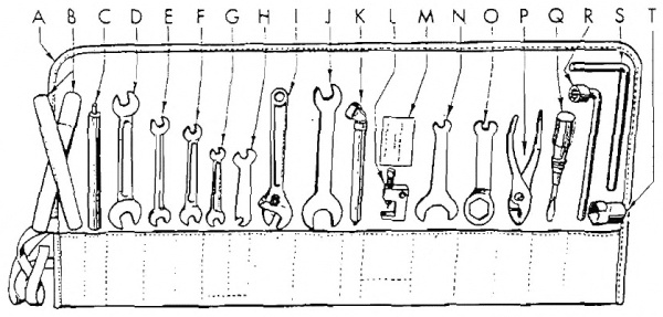
21. VEHICLE TOOLS (fig. 11).
a. Kits. Included in the tool kit assembly are the following:
a. Kits. The tool kit assembly includes the following:
| Legend Letter for Fig. 11 |
Tool | Number of Cars | Manufacturer's Number | Federal Stock Number | Where it's stored |
|---|---|---|---|---|---|
| A | Tool roll Tool pouch |
1 | 11819–44 | Please provide the text you'd like me to modernize. | In saddle bag |
| B | Irons, tire Wheels, tire |
2 | 11551–X | 41–I–773–75 | In tool roll |
| *C | Handle, chain tool Handle, chain tool |
1 | 11817–40 | 41–H–1510–400 | In tool roll |
| D | Wrench, 5⁄8–in. by ¾–in. Wrench, 5/8 in. by ¾ in. |
1 | 11804–44C | Understood! Please provide the text you would like me to modernize. | In tool roll |
| E | Wrench, ½–in. by 9⁄16–in. ½-inch wrench by 9/16-inch |
1 | 11804–44B | Understood. Please provide the text you'd like me to modernize. | In tool roll |
| F | Wrench, 7⁄16–in. by ½–in. Wrench, 7/16 in. by ½ in. |
1 | 11804–44A | Sure! Please provide the text you would like me to modernize. | In tool roll |
| G | Wrench, 5⁄16–in. by 3⁄8–in. Wrench, 5/16 in. by 3/8 in. |
1 | 11804–44 | Understood. Please provide the text you would like to be modernized. | In tool roll |
| H | Wrench, ⅜–in. by 7⁄16–in. (valve tappet) Wrench, ⅜ in. by 7/16 in. (valve tappet) |
1 | 11905–X | Understood! Please provide the text you'd like me to modernize. | In tool roll |
| I | Wrench, adjustable Adjustable wrench |
1 | 11813–44 | Understood! Please provide the text you would like modernized. | In tool roll |
| *J | Wrench, ¾–in. by 1¾–in. (rear axle nut and trans.) Wrench, ¾ in. by 1¾ in. (rear axle nut and transmission) |
1 | 11814–35 | 41–W–1989–850 | In tool roll |
| K | Gage, tire Gauge, tire |
1 | 11562–43 | I'm ready to assist! Please provide the text you would like me to modernize. | In tool roll36 |
| *L | Tool, chain repair Tool for chain repair |
1 | 12039–38 | Understood. Please provide the text you would like me to modernize. | In tool roll |
| *M | Washers, 0.002–in. thick (chain oiler adj.) Washers, 0.002 inches thick (chain oiler adjustment) |
4 | 674–32 | Sure! Please provide the short phrases you would like me to modernize. | In tool roll |
| *N | Wrench, 7⁄16–in. by 1⅜–in. (valve cover) Wrench, 7/16 in. by 1⅜ in. (valve cover) |
1 | 11806–31 | 41–W–3617 | In tool roll |
| *O | Wrench, 7⁄16–in. by 11⁄8–in. (use with spark plug socket) Wrench, 7⁄16–in. by 11⁄8–in. (use with spark plug socket) |
1 | 11929–39 | Understood. Please provide the text you would like me to modernize. | In tool roll |
| *P | Pliers, adjustable Adjustable pliers |
1 | 11812–44 | I'm ready to assist! Please provide the text you want modernized. | In tool roll |
| *Q | Screwdriver Screwdriver |
1 | 11811–X | Sure! Please provide the short piece of text you'd like me to modernize. | In tool roll |
| R | Wrench, 9⁄16–in. socket (cyl. head bolt) 9/16-inch socket wrench (cyl. head bolt) |
1 | 12047–30A | 41–W01525 | In tool roll |
| *S | Wrench, wheel mounting Wrench, wheel install |
1 | 11815–35 | 41–W–3825–400 | In tool roll |
| *T | Wrench, socket (spark plug; use with O) Wrench, socket (spark plug; use with O) |
1 | 11805–40 | 41–W–3332 | In tool roll |
Pump, tire Inflate tire |
1 | 11553–41M | 8–P–4900 | On frame, left side | |
Grease gun (in case) Grease gun (if needed) |
1 | 11661–38A | Understood! Please provide the text you would like me to modernize. | In saddle bag |
*EXCEPTION: Earlier models furnished with smaller tool roll and kit contain the items marked by asterisk.
*EXCEPTION: Earlier models equipped with a smaller tool roll and kit contain the items marked with an asterisk.
22. VEHICLE EQUIPMENT (figs. 12 and 13).
a. Attached to Vehicle.
a. Mounted on Vehicle.
| Item | Count of Cars | Where It's Carried |
|---|---|---|
Saddlebags Bike bags |
2 | On luggage carrier On luggage rack |
Mirror, rear view Rearview mirror |
1 | On left handle bar On the left handlebar |
Box, submachine gun ammunition Box, submachine gun ammo |
1 | Front fender, left side Left front fender |
Bracket, submachine gun carrier Bracket, submachine gun holder |
1 | Front fender, right side Right front fender |
Guard, front safety Front safety guard |
1 | Attached to frame Mounted on frame |
Guard, rear safety Back safety guard |
1 | Attached to frame Attached to the frame |
Windshield, cpt Windshield, captain |
1 | On handle bar On handlebars |
Leg shields, cpt (right and left) Leg shields, cpt (right and left) |
2 | Attached to frame Framed attachment |

RA PD 310216
Figure 12—Vehicle Equipment, Left Side
RA PD 310216
Figure 12—Vehicle Equipment, Left Side
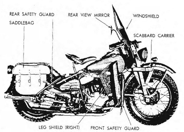
RA PD 310217
Figure 13—Vehicle Equipment, Right Side
RA PD 310217
Figure 13—Vehicle Equipment, Right Side

23. VEHICLE SPARE PARTS (fig. 14).
| Item | Number of Carriers | Where It's Carried | |
|---|---|---|---|
| A | Roll, parts kit Parts kit roll |
1 | In saddlebag In saddle bag |
| H | Plug, spark (and gasket) Plug, spark, and gasket |
1 | In kit roll In the kit |
| F | Link, rear chain repair Link, rear chain fix |
1 | In kit roll In the kit |
| G | Link, front chain repair Link, front derailleur repair |
1 | In kit roll In the kit |
| K | Lamp‐unit, tail blackout Lamp unit, tail blackout |
1 | In kit roll In kit bag |
| J | Lamp‐unit, stop blackout Light fixture, stop blackout |
1 | In kit roll In a kit roll |
| L | Lamp‐unit, tail and stop Lamp unit, tail, and stop |
1 | In kit roll In a kit roll |
| B | Lamp bulk kit, head lamps, 5 bulbs Lamp bulk kit, headlamps, 5 bulbs |
1 | In kit roll In kit roll-up |
| C | Kit, tire repair Tire repair kit |
1 | In kit roll In toolkit |
| I | Tape, friction Sticky tape |
1 | In kit roll In kit bag |
| D | Caps, tire valve (5 in box) Caps, tire valve (5 per box) |
1 | In kit roll In the kit |
| E | Cores, tire valve (5 in box) Cores, tire valve (5 in a box) |
1 | In kit roll In kit bag |
PART TWO—VEHICLE MAINTENANCE INSTRUCTIONS
Section 7
Maintenance Budget
24. SCOPE.
a. The scope of maintenance and repair by the crew and other units of the using arms is determined by the availability of suitable tools, availability of necessary parts, capabilities of the mechanics, time available, and the tactical situation. All of these are variable and no exact system of procedure can be prescribed.
a. The extent of maintenance and repairs done by the crew and other units using the equipment depends on the tools available, the necessary parts on hand, the skills of the mechanics, the time they have, and the tactical situation. All of these factors can change, so there can't be a fixed procedure.
25. ALLOCATION OF MAINTENANCE.
a. Indicated below are the maintenance duties for which tools and parts have been provided for the using arm and maintenance personnel. Replacements and repairs which are the responsibility of ordnance maintenance personnel may be performed by using arm personnel when circumstances permit, within the discretion of the commander concerned. Echelons and words as used in this list of maintenance allocations are defined as follows:
a. Below are the maintenance duties for which tools and parts have been provided for the using arm and maintenance personnel. Replacements and repairs that are usually the responsibility of ordnance maintenance personnel may be carried out by using arm staff when circumstances allow, at the discretion of the relevant commander. The echelons and terms used in this list of maintenance allocations are defined as follows:
| First and Second Level: Table III AR 850–15 |
Operating organization driver, operator or crew, companies and detachments, battalions, squadrons, regiments, and separate companies and detachments (first and second echelons, respectively). |
| Third Echelon: Table III AR 850–15 |
Technical light and medium maintenance units, including post and port shops. |
| Fourth Echelon: Table III AR 850–15 |
Technical heavy maintenance and field depot units including designated post and service command shops. |
| Fifth Level: Table III AR 850–15 |
Technical base units. |
| Service: (Including preventive maintenance) par. 24 a (2) and (3) in part AR 850–15 |
Checking and replenishing fuel, oil, grease, water and antifreeze, air, and battery liquid; checking and tightening nuts and bolts; cleaning. |
| Service: (Including preventive maintenance) par. 24 a (2) and (3) in part AR 850–15 |
Checking and replenishing fuel, oil, grease, water and antifreeze, air, and battery liquid; checking and tightening nuts and bolts; cleaning. |
| 40Replace: Par. 24 a (5) AR 850–15 |
To remove an unserviceable part, assembly, or subassembly from a vehicle and replace it with a serviceable one. |
| Fix: Par. 24 a (6) in part AR 850–15 |
To restore to a serviceable condition, such parts, assemblies or subassemblies as can be accomplished without completely disassembling the assembly or subassembly, and where heavy riveting, or precision machining, fitting, balancing, or alining is not required. |
| Reconstruct: Par. 24 a (6) AR 850–15 |
Consists of stripping and completely reconditioning and replacing in serviceable condition any vehicle or unserviceable part, subassembly, or assembly of the vehicle, including welding, riveting, machining, fitting, alining, balancing, assembling, and testing. |
| Restoration: AR 850–15 Par. 4 (c) in part CIR. 75, dated 16 March ’43 |
Salvage of serviceable or economically repairable units and parts removed from vehicles, and their return to stock. This includes the process which recovers and/or reclaims unusable articles or component parts thereof and places them in a serviceable condition. |
NOTES: (1) Operations allocated will normally be performed in the
echelon indicated by X.
(2) Operations allocated to the third echelon as indicated by E may
be performed by these units in emergencies only.
(3) Operations allocated to the fourth echelon by E are normally
fifth echelon operations. They will not be performed by the fourth
echelon, unless the unit is expressly authorized to do so by the
chief of the service concerned.
NOTES: (1) Assigned operations will usually be carried out in the level indicated by X.
(2) Assigned operations to the third level, as marked by E, may only be carried out by these units in emergencies.
(3) Assigned operations to the fourth level by E are typically operations of the fifth level. They will not be executed by the fourth level unless the unit is specifically authorized to do so by the chief of the relevant service.
| Levels | ||||
|---|---|---|---|---|
| CLUTCH | 2nd | 3rd | 4th | 5th |
| Bearings, clutch release—replace | X | |||
| Clutch—replace and/or repair (reline) | X | |||
| Hub, clutch—replace | X | |||
| Hub, clutch—repair | X | |||
| Sprocket assembly, clutch—replace | X | |||
| Sprocket assembly, clutch—repair | X | |||
| CONTROLS AND LINKAGE | ||||
| Controls and linkage—service and/or replace | X | |||
| Controls and linkage—repair | X | |||
| 41ELECTRICAL GROUP | ||||
| Battery—service (recharge) and/or replace | X | |||
| Battery—repair | X | |||
| Battery—rebuild | E | X | ||
| Cables, battery—replace and/or repair | X | |||
| Coil, ignition—replace | X | |||
| Head, speedometer—replace | X | |||
| Head, speedometer—repair | X | |||
| Head, speedometer—rebuild | X | |||
| Horn assembly—replace | X | |||
| Horn assembly—repair | X | |||
| Light assemblies—service and/or replace | X | |||
| Light assemblies—repair | X | |||
| Panel, instrument—replace | X | |||
| Panel, instrument—repair | X | |||
| Switch assemblies—replace | X | |||
| Switch assemblies—repair | X | |||
| Wiring—replace | X | |||
| ENGINE | ||||
| (V–45″–Twin Engine) | ||||
| Bearings, main—replace | E | X | ||
| Bearings, connecting rod—replace | E | X | ||
| Breaker assembly, circuit—replace | X | |||
| Breaker assembly, circuit—repair | X | |||
| Breaker assembly, circuit—rebuild | X | |||
| Carburetor—replace | X | |||
| Carburetor—repair | X | |||
| Carburetor—rebuild | X | |||
| Cleaner, air—service and/or replace | X | |||
| Cleaner, air—repair | X | |||
| Cleaner, air—rebuild | X | |||
| Cylinder assembly—replace | X | |||
| Cylinder assembly—repair | X | |||
| Cylinder assembly—rebuild (recondition) | E | X | ||
| Condenser—replace | X | |||
| Engine assembly—replace | *4 | X | ||
| 42 Engine assembly—repair | X | |||
| Engine assembly—rebuild | E | X | ||
| Gasket, cylinder head—replace | X | |||
| Gears, timing—replace | E | X | ||
| Generator assembly—replace | X | |||
| Generator assembly—repair | X | |||
| Generator assembly—rebuild | X | |||
| Head, cylinder—replace and/or repair | X | |||
| Lines and connections—replace | X | |||
| Lines and connections—repair | X | |||
| Pistons, rings and pins assembly—replace | E | E | X | |
| Plug, spark—replace | X | |||
| Points, circuit breaker—service and/or replace | X | |||
| Pump assembly, feed—replace | X | |||
| Pump assembly, feed—repair | X | |||
| Pump assembly, feed—rebuild | X | |||
| Pump assembly, oil—replace | X | |||
| Pump assembly, oil—repair | X | |||
| Pump assembly, oil—rebuild | X | |||
| Pump assembly, oil scavenger—replace and/or repair | X | |||
| Pump assembly, oil scavenger—rebuild | X | |||
| Rod, connecting—replace and/or rebuild (recondition) | X | X | ||
| Sprocket, engine—replace | X | |||
| Strained gasoline—replace and/or repair | X | |||
| Valves—service | X | |||
| EXHAUST GROUP | ||||
| Muffler and exhaust pipe—replace | X | |||
| Muffler and exhaust pipe—repair | X | |||
| MISCELLANEOUS | ||||
| Bars, safety—replace | X | |||
| Bars, safety—repair | X | |||
| Boxes, ammunition, battery and tool—replace | X | |||
| Boxes, ammunition, battery and tool—repair | X | |||
| Carriers, luggage and scabbard—replace | X | |||
| Carriers, luggage and scabbard—repair | X | |||
| Frame—replace and/or rebuild | E | X | ||
| Guards, mud—replace | X | |||
| 43Guards, mud—repair | X | |||
| Plate, skid—replace | X | |||
| Plate, skid—repair | X | |||
| Saddle—replace | X | |||
| Saddle—repair | X | |||
| Saddle—rebuild | X | |||
| Springs, saddle post—replace | X | |||
| Tank, fuel—replace | X | |||
| Tank, fuel—repair | X | |||
| Tank, oil—replace | X | |||
| Tank, oil—repair | X | |||
| SUSPENSION (FRONT) | ||||
| Bars, handle—replace | X | |||
| Bars, handle—repair | X | |||
| Damper, steering—replace | X | |||
| Drum, brake—replace | X | |||
| Fork, front assembly—replace | X | |||
| Fork, front assembly—repair | X | |||
| Fork, front assembly—rebuild | X | |||
| Fork, spring—replace | X | |||
| Fork, spring—repair | X | |||
| Fork, spring—rebuild | X | |||
| Plate, rocker—replace | X | |||
| Plate, rocker—repair | X | |||
| Shoe assembly, brake—service and/or replace | X | |||
| Shoe assembly, brake—repair (reline) | X | |||
| Springs, cushion and rebound—replace | X | |||
| SUSPENSION (REAR) | ||||
| Chains, all—replace and/or repair | X | |||
| Drum, brake, rear—replace | X | |||
| Guards, chains—replace | X | |||
| Guards, chains—repair | X | |||
| Shoe assemblies, brake—service and/or replace | X | |||
| Shoe assemblies, brake—repair (reline) | X | |||
| Sprocket, rear—replace | X | |||
| Wheels—replace | X | |||
| Wheels—repair | X | |||
| Wheels—rebuild | E | X | ||
| 44 TIRES | ||||
| Casings and tubes—replace | X | |||
| Casings—repair | E | X | ||
| Tubes, inner—repair | X | |||
| TRANSMISSION | ||||
| Spring, kick starter—replace | X | |||
| Sprocket, transmission countershaft—replace | X | |||
| Starter, kick—replace | X | |||
| Starter, kick—repair | X | |||
| Transmission—replace | *4 | X | ||
| Transmission—repair | X | |||
| Transmission—rebuild | E | X | ||
| VEHICLE ASSEMBLY | ||||
| Motorcycle—service | X | |||
| Motorcycle—rebuild (with serviceable unit assemblies) | X | E | ||
4 The second echelon is authorized to remove and reinstall items marked by an asterisk. However, when it is necessary to replace an item marked by an asterisk with a new or rebuilt part, subassembly or unit assembly, the assembly marked by an asterisk may be removed from the vehicle by the second echelon only after authority has been obtained from a higher echelon of maintenance.
4 The second level of maintenance can take off and put back items marked with an asterisk. However, if a part marked with an asterisk needs to be replaced with a new or rebuilt part, subassembly, or unit assembly, the assembly marked with an asterisk can only be removed from the vehicle by the second level after getting approval from a higher level of maintenance.
Section 8
Second echelons preventive maintenance
| Below is a short piece of text (5 words or fewer). Modernize it into contemporary English if there's enough context, but do not add or omit any information. If context is insufficient, return it unchanged. Do not add commentary, and do not modify any placeholders. If you see placeholders of the form __A_TAG_PLACEHOLDER_x__, you must keep them exactly as-is so they can be replaced with links. | |
|---|---|
| Second echelon preventive maintenance services | 26 |
26. SECOND ECHELON PREVENTIVE MAINTENANCE SERVICES.
a. Regular scheduled maintenance inspections and services are a preventive maintenance function of the using arms, and are the responsibility of commanders of operating organizations.
a. Regularly scheduled maintenance inspections and services are a preventive maintenance task for the using units and are the responsibility of the commanders of operational organizations.
(1) Frequency. The frequencies of the preventive maintenance services outlined herein are considered a minimum requirement for normal operation of vehicles. Under unusual operating conditions such as extreme temperatures, and dusty or sandy terrain, it may be necessary to perform certain maintenance services more frequently.
(1) Frequency. The frequencies for the preventive maintenance services listed here are seen as the minimum needed for regular vehicle operation. In unusual operating conditions, like extreme temperatures or dusty or sandy areas, it might be necessary to carry out some maintenance services more often.
(2) First Echelon Participation. The drivers should accompany their vehicles and assist the mechanics while periodic second echelon preventive maintenance services are performed. Ordinarily the driver should present the vehicle for a scheduled preventive maintenance service in a reasonably clean condition; that is, it should be dry, and not caked with mud or grease to such an extent that inspection and servicing will be seriously hampered. However, the vehicle should not be washed or wiped thoroughly clean, since certain types of defects, such as cracks, leaks, and loose or shifted parts or assemblies are more evident if the surfaces are slightly soiled or dusty.
(2) First Echelon Involvement. The drivers should stay with their vehicles and help the mechanics during regular second echelon preventive maintenance services. Generally, the driver should bring the vehicle in for a scheduled preventive maintenance service in a reasonably clean condition; meaning it should be dry and not covered in mud or grease to the point that it makes inspection and servicing difficult. However, the vehicle shouldn’t be washed or cleaned too well, as certain types of defects, like cracks, leaks, and loose or shifted parts, are easier to spot if the surfaces are slightly dirty or dusty.
(3) If instructions other than those contained in the general procedures in paragraph (4) or the specific procedures in paragraph (5) which follow, are required for the correct performance of a preventive maintenance service, or for correction of a deficiency, other sections of the vehicle operator’s manual pertaining to the item involved, or a designated individual in authority, should be consulted.
(3) If instructions beyond those in the general procedures in paragraph (4) or the specific procedures in paragraph (5) are needed for properly completing a preventive maintenance service or for fixing a deficiency, you should refer to other sections of the vehicle operator’s manual that relate to the item in question, or consult an authorized individual.
(4) General Procedures. These general procedures are basic instructions which are to be followed when performing the services on the items listed in the specific procedures. The second echelon personnel must be thoroughly trained in these procedures so that they will apply them automatically.
(4) Standard Operating Procedures. These general procedures are fundamental instructions to follow when carrying out the services on the items detailed in the specific procedures. The second echelon personnel must be fully trained in these procedures to apply them automatically.
(a) When new or overhauled subassemblies are installed to correct deficiencies, care should be taken to see that they are clean, correctly installed, properly lubricated, and adjusted.
(a) When new or refurbished subassemblies are installed to fix issues, it's important to ensure they are clean, installed correctly, properly lubricated, and adjusted.
(b) When installing new lubricant retainer seals, a coating of the lubricant should be wiped over the sealing surface of the lip of the seal.
(b) When putting in new lubricant retainer seals, a layer of the lubricant should be spread over the sealing surface of the lip of the seal.
(c) The general inspection of each item applies also to any supporting member or connection, and usually includes a check to see46 whether the item is in good condition, correctly assembled, secure, or excessively worn. The mechanics must be thoroughly trained in the following explanations of these terms:
(c) The overall inspection of each item also includes any supporting member or connection, and typically involves checking to see46 if the item is in good condition, properly assembled, secure, or overly worn. The mechanics need to be thoroughly trained in the following explanations of these terms:
1. The inspection for “good condition” is usually an external visual inspection to determine whether or not the unit is damaged beyond safe or serviceable limits. The term “good condition” is explained further by the following: not bent or twisted, not chafed or burned, not broken or cracked, not bare or frayed, not dented or collapsed, not torn or cut.
1. The inspection for “good condition” is usually a visual check from the outside to see if the unit is damaged beyond safe or usable limits. The term “good condition” is explained further by the following: not bent or twisted, not worn or burned, not broken or cracked, not exposed or frayed, not dented or collapsed, not torn or cut.
2. The inspection of a unit to see that it is “correctly assembled” is usually an external visual inspection to see whether or not it is in its normal assembled position in the vehicle.
2. The inspection of a unit to check if it is “correctly assembled” is typically an external visual inspection to determine whether it is in its standard assembled position in the vehicle.
3. The inspection of a unit to determine if it is “secure” is usually an external visual examination, a hand‐feel, or a pry‐bar check for looseness; such an inspection should include any brackets, lock washers, lock nuts, locking wires, or cotter pins used in assembly.
3. Checking a unit to see if it is “secure” usually involves a visual look from the outside, a physical check by hand, or using a pry bar to test for looseness; this inspection should cover any brackets, lock washers, lock nuts, locking wires, or cotter pins used in the assembly.
4. “Excessively worn” will be understood to mean worn, close to or beyond serviceable limits, and likely to result in a failure if not replaced before the next scheduled inspection.
4. “Excessively worn” refers to items that are worn down to or beyond their usable limits and are likely to fail if not replaced before the next scheduled inspection.
(d) Special Services. These are indicated by repeating the item numbers in the columns which show the interval at which the services are to be performed, and show that the parts, or assemblies, are to receive certain mandatory services. For example, an item number in one or both columns opposite a Tighten procedure, means that the actual tightening of the object must be performed. The special services include:
(d) Special Services. These are shown by repeating the item numbers in the columns that indicate how often the services should be performed, and they specify that the parts or assemblies must receive certain required services. For instance, an item number in one or both columns next to a Tighten procedure means that the actual tightening of the object must be done. The special services include:
1. Adjust. Make all necessary adjustments in accordance with the pertinent section of the vehicle operator’s manual, special bulletins, or other current directives.
1. Adjust. Make all necessary adjustments according to the relevant section of the vehicle operator’s manual, special bulletins, or other current guidelines.
2. Clean. Clean units of the vehicle with dry‐cleaning solvent to remove excess lubricant, dirt, and other foreign material. After the parts are cleaned, rinse them in clean dry‐cleaning solvent, and dry them thoroughly. Take care to keep the parts clean until reassembled, and be certain to keep dry‐cleaning solvent away from rubber or other material which it will damage. Clean the protective grease coating from new parts, since this material is not a good lubricant.
2. Clean. Use dry-cleaning solvent to clean the vehicle's units and remove any excess lubricant, dirt, and other debris. After cleaning the parts, rinse them in clean dry-cleaning solvent and dry them completely. Make sure to keep the parts clean until they are reassembled and avoid letting dry-cleaning solvent come into contact with rubber or other materials that it could damage. Remove the protective grease coating from new parts, as this material is not an effective lubricant.
3. Special lubrication. This applies both to lubrication operations that do not appear on the vehicle Lubrication Guide, and to items that do appear on such guides, but should be performed in connection with the maintenance operations, if parts have to be disassembled for inspection or service.
3. Special lubrication. This includes lubrication tasks that aren't listed in the vehicle Lubrication Guide, as well as those that are included in the guide but should be done during maintenance operations if parts need to be taken apart for inspection or servicing.
4. Serve. This usually consists of performing special operations, such as replenishing battery water, and draining and refilling units with oil.
4. Serve. This typically involves doing specific tasks, like topping off battery water and draining and refilling units with oil.
5. Tighten. All tightening operations should be performed with sufficient wrench‐torque (force on the wrench handle) to tighten the nut according to good mechanical practice. Use torque‐indicating wrench where specified. Do not overtighten, as this may strip threads, or cause distortion. Tightening will always be understood to include the correct installation of lock washers, lock nuts, and cotter pins provided to secure the tightening.
5. Tighten. All tightening tasks should be done with enough wrench torque (force on the wrench handle) to secure the nut following good mechanical practices. Use a torque-indicating wrench where needed. Don’t overtighten, as this can strip threads or cause distortion. Tightening should always mean the proper installation of lock washers, lock nuts, and cotter pins included to secure the tightening.
(e) When conditions make it difficult to perform the complete preventive maintenance procedures at one time, these can sometimes be handled in sections, planning to complete all operations within the task if possible. All available time at halts and in bivouac areas must be utilized, if necessary, to assure that maintenance operations are completed. When limited by the tactical situation, items with special services in the columns should be given first consideration.
(e) When it's hard to do all the preventive maintenance procedures at once, they can sometimes be broken down into sections. The goal is to finish all tasks if possible. All available time during stops and in temporary camp areas should be used, if needed, to ensure maintenance tasks are completed. When limited by the tactical situation, items needing special attention should be prioritized.
(f) The numbers of the preventive maintenance procedures that follow are identical with those outlined on W.D. AGO Form No. 463, which is the Preventive Maintenance Service Work Sheet for Motorcycles. Certain items on the work sheet that do not apply to this vehicle are not included in the procedures in this manual. In general, the numerical sequence of items on the work sheet is followed in the manual procedures, but in some instances there is deviation for conservation of the mechanic’s time and effort.
(f) The numbers for the preventive maintenance procedures listed below are the same as those found on W.D. AGO Form No. 463, which is the Preventive Maintenance Service Work Sheet for Motorcycles. Certain items on the work sheet that don’t apply to this vehicle are not included in the procedures in this manual. Generally, the numerical order of items on the work sheet is mirrored in the manual procedures, but in some cases, adjustments have been made to save the mechanic’s time and effort.
(5) Specific Procedures. The procedures for performing each item in the 1,000‐mile maintenance procedures are described in the following chart. Each page of the chart has a column at its left edge corresponding to the 1,000‐mile maintenance.
(5) Specific Procedures. The steps for carrying out each task in the 1,000-mile maintenance procedures are detailed in the chart below. Each page of the chart includes a column on the left side that corresponds to the 1,000-mile maintenance.
ROAD TEST
Test Drive
| 1000-Mile Service | NOTE: If the tactical situation doesn't allow for a complete road test, carry out items 2, 3, 4, 5, 6, 7, 8, 9, 12, and 14, which require minimal or no movement of the vehicle. When a road test can be done, it should ideally last for 5 miles, but not exceed 10 miles. |
|---|---|
| 1 | Before‐operation Inspection. Perform Before‐operation Service listed on W.D. Form No. 418. “Driver’s Trip Ticket and Preventive Maintenance Service Record” (described in par. 15), to determine if vehicle is in a satisfactory condition to make the road test safely. |
| 2 | Ease of Starting. Start engine and observe action of starter. Note if engine responds readily. |
| 3 | Oil Circulation. Oil circulation is normally indicated by oil signal light (red light) in instrument panel being out. When red light is on, oil is not circulating. Observe for48 excess smoke in exhaust. CAUTION: If red light fails to go out after engine has been started, stop engine at once. Refer to paragraph 30 for possible causes. |
| 4 | Instruments. Observe instruments for proper or normal indication and functioning of system to which they apply. |
| Speed and Distance Tracker. Speedometer must indicate vehicle speed without excessive noise or fluctuation; odometer must record trip and total mileage. Oil Pressure Warning Light. Note whether oil signal light (red light) indicates correctly. After ignition switch is turned on, and before starting engine, the red light should go on, indicating no oil circulation. When engine is started, light should go out. | |
| Generator Signal Light. With switch on, and before starting engine, the green signal light should go on, indicating discharge of battery. After starting engine, increase engine speed to a medium fast idle; green signal light should then go out, indicating generator is charging battery. CAUTION: Continue observation of signal lights during road test, and if lights should fail to operate as indicated above, stop engine, investigate cause, and correct or report trouble to proper authority. | |
| 5 | Brake Operation. Test foot brake for safe stop within reasonable distance. Note squeaks or chatter that might indicate wet, oily, dirty, or loose lining, damaged drum, or improper adjustment. Apply hand‐operated front brake only in conjunction with rear brake and observe whether it operates effectively in assisting to make a quicker stop. |
| 6 | Clutch Operation. Before moving vehicle, make sure that clutch pedal has satisfactory free travel before it begins to disengage clutch; that it releases clutch completely before reaching end of travel; and that there are no unusual noises in clutch‐release mechanism. When starting vehicle, observe whether clutch grabs, chatters, or slips when fully engaged. |
| 7 | Gearshift. Shift through entire gear range of transmission and observe whether mechanism operates freely without clashing or jumping out of gear. Note any unusual vibration that might indicate loose engine or transmission mountings. |
| 8 | Unusual Noises. During entire road test, listen for unusual
noises that might indicate worn, loose, damaged, or insufficiently
lubricated parts in the entire motorcycle, particularly in engine
and accessories, or in the power train. 49 CAUTION: Loose primary (front) drive chain, with slack in excess of ½ inch total up‐and‐down motion, can cause excessive noise which sounds like engine knock. Remove inspection cover for examination of chain. |
| 9 | Steering. Observe steering mechanism for indication of looseness or excessive binding through full turning range. With hands resting lightly on handle bars and vehicle in vertical position, observe whether there is any tendency to pull to one side when operating at a reasonable speed. Note any indication of steering instability at higher speeds. |
| 10 | Balance. If vehicle does not balance properly in operation, inspect for misalinement of rear wheel. |
| 11 | Speedometer and Odometer. Inspect speedometer for proper operation, excessive fluctuation, or unusual noise. Observe odometer for correct recording of trip and total mileage. |
| 12 | Throttle and Spark Controls. Set throttle stop screw and low speed needle adjustment so that engine will operate smoothly and will not stall at idling speed. With vehicle running at a speed of 30 miles per hour, or faster, in high gear, turn throttle control grip to “OPEN” and “CLOSED” positions and note whether engine responds instantly to throttle changes. Turn spark control grip and note whether it fully advances and retards ignition timer. |
| 13 | Power and Operation. Observe engine for normal pulling power, and good operating characteristics in each speed, from first to high gear. Also observe whether engine misses, stalls, knocks excessively, or makes any other unusual noise. |
| 14 | Carburetor Adjustment. No carburetor adjustment, other than idle adjustment as performed in item 12, is required on this vehicle. |
| 15 | Brake Drum and Hub Temperature. Immediately after completing road test, feel front and rear brake drums and wheel hubs for overheating. |
| 16 | Power Train Temperatures. Feel transmission for overheating. |
| Maintenance Work | |
| 17 | Compression Test. With throttle wide‐open, test compression with starter. If engine lacks compression, inspect for leaks. |
| 18 | Transmission. Inspect transmission for good condition, secure mounting, and leaks. Inspect oil level. Drain and refill50 transmission to level of transmission filler plug opening with specified grade of engine oil. CAUTION: Always drain transmission immediately after it has been warmed and agitated by operation of engine. Refill as soon as draining is completed to avoid hazard of operating without lubricant. Tighten all mounting and assembly bolts securely. |
| 20 | Engine Oil. Inspect oil tank for oil level: drain and refill tank. CAUTION: Fill to within 1 inch of filler opening and filler cap with specified weight of oil. Always drain immediately after engine operation and refill as soon as draining is completed, to avoid hazard of operating without lubricant. |
| 21 | Battery and Carrier. Clean top of battery. See that battery and carrier are in good condition, and that carrier is securely mounted. Remove cell caps: make sure that vents are open. Test specific gravity with hydrometer and record readings on work sheet, W.D. AGO Form No. 463. Readings below 1.225 indicate need for recharge, or battery failure. Variation between cells of more then 0.025 must be reported. Read and record voltage of battery (6‐volt reading is normal). Bring electrolyte to 5⁄16 inch above tops of plates, using clean, drinkable water. If excessive looseness of battery in case is noted, check for presence of rubber pad in bottom of case, and make sure rubber pad is installed on top of battery, when battery service is completed. |
| 22 | Battery Wires and Terminals. Inspect battery for good condition and secure connections. Look for worn spots in wire insulation. Oil the felt washers on battery terminals. |
| 23 | Electrical Wiring. Inspect all electric wiring to see that it is in good condition, securely attached, and connected. Look for worn spots in insulation. |
| 24 | Generator Drive and Mounting, and Relay. Inspect generator for secure mounting. After removing left footboard assembly, remove generator and cover. Examine commutator for cleanliness, good condition, or excessive wear. If commutator is dirty, it must be cleaned with No. 00 sandpaper. Blow out with compressed air. If commutator is in bad condition or excessively worn, replace generator. Remove relay cover, being careful to avoid damage to mechanism, and inspect for cleanliness. Blow out with air if wet or dirty. CAUTION: Do not attempt to adjust relay, or to clean it in any other manner. |
| 25 | Timer (Circuit Breaker). Clean and remove timer cover. See that wiring leads are securely connected and that inside 51of the timer is clean. Inspect breaker points to see that they are clean, well‐lined, engaging squarely, and are not excessively pitted, burned, or worn. See that condenser mounting screw is tight. Breaker lever should be free on its pivot and well insulated from the pivot pin. Determine if breaker arm spring exerts normal force against arm. Examine camshaft by hand‐feel to see whether it is excessively worn in its bushings; if camshaft bushings are worn excessively, install new timer. If points are slightly burned or pitted, dress them with a fine file. If breaker points are unserviceable, install a new set, taking care to aline them and to adjust gap to 0.022 inch. Apply one drop of oil to breaker arm pivot pin. Use clean cloth to wipe cam and then coat with a very light film of light grease. CAUTION: Be careful to avoid getting oil or grease on breaker points. |
| 26 | Spark Plugs. Remove spark plugs, clean with sandblast cleaner, and inspect for cracked insulators: inspect electrodes for good condition and adjust gap to 0.025 to 0.030 inch; replace faulty plugs. Be sure to install new gasket with new plug. Inspect radio suppressors on plug cables for good condition and secure attachment. |
| 27 | Ignition and Light Switch. Make sure that the switch is in good condition and operating properly in all positions. |
| 28 | Lights, Service and Blackout. See that all lights are clean, in good condition, properly aimed, and securely mounted. Tactical situation permitting, turn switch to each of its positions and observe whether service and blackout lights operate properly, and whether they go out when switched off. Operate dimmer switch on left handle bar to see whether it depresses beam of service headlight. Apply foot brake for check of both blackout and service stop light operation. Inspect lenses for breakage, and headlight reflector for discoloration. Clean all lenses. |
| 29 | Horn. Tactical situation permitting, sound horn to test for normal signal. Examine horn for good condition, secure mounting, and tight wiring connections. |
| 30 | Cylinder Heads. If cylinder head gaskets show signs of leakage, tighten head bolts: if leakage persists, new gaskets should be installed. A head bolt wrench (Fed‐Stock No. 41–W–1525) is available with which head bolts can be tightened without removing tanks for wrench clearance. If tanks are removed to permit taking off heads and installing52 new gaskets, bolts should then be tightened evenly with a torque wrench to a tension of 60 foot‐pounds minimum, or 65 foot‐pounds maximum, when engine is cold. |
| 31 | Cylinder Hold‐down Nuts. If these nuts are loose, or there is excessive oil leakage around cylinder bases, tighten nuts evenly when engine is cold. If excessive leakage persists, new gaskets should be installed. CAUTION: If cylinder base nuts are loose, perform item 36 before starting engine. |
| 32 | Engine Mountings. Inspect top engine mounting bracket and bolt for good condition and security. CAUTION: Tight seating of the engine bracket mounting bolt is a necessity for effective radio bonding. Inspect four lower engine mounting bolts for signs of looseness. Tighten as required. |
| 33 | Engine Crankcase. Examine engine crankcase for good condition and for leaks. Make sure timing gear cover screws, and oil feed and scavenger pump nuts, are tight. |
| 34 | Intake Manifold. Examine manifold for good condition and secure mounting. Make sure manifold nuts are tight. |
| 35 | Muffler and Exhaust Pipes. Inspect muffler and exhaust pipes for good condition, secure mounting, and for leaks. Be sure tail pipe opening is not restricted. |
| 36 | Valve Mechanism. When engine is cold, adjust valve tappet clearance to 0.004–inch minimum, 0.005–inch maximum on intake valve; 0.006–inch minimum, 0.007–inch maximum on exhaust valve. See that valve springs are in good condition and properly secured; that valve tappet adjusting screws and lock nuts are in good condition; and that valve covers are in good condition, secure, and not leaking oil. |
| 37 | Starter. Examine pedal, crank, and return spring for good condition, correct assembly, and secure mounting. Starter should operate without binding, and return spring should bring starter crank to its disengaged position when foot pressure is removed. CAUTION: Make sure that starter crank pinch bolt is installed with head of bolt toward rear of vehicle when crank is in upright position. |
| 38 | Engine Cooling Fins. Inspect engine cooling fins for good condition and cleanliness. Remove all dirt or foreign matter. Do not apply paint to cooling fins. |
| 39 | Filler Caps and Vents. Wipe dirt and dust from filler caps of fuel and oil tanks. Inspect caps and gaskets to see that they are in good condition. Note whether vent in fuel filler 53cap is open. Reinstall caps, observing that each locks properly on filler neck. Do not interchange fuel and oil tank filler caps. |
| 40 | Fuel Tank Valves and Lines. See that valves and lines are in good condition, secure, and not leaking. Test fuel shut‐off valve for ample friction to hold valve in reserve position. See that valve lifts freely enough to operate satisfactorily. |
| 41 | Oil System Leaks. Examine oil tank, oil lines, vent line, and connections for good condition, secure attachment, and for leaks. |
| 42 | Carburetor and Fuel Filter (Gasoline Strainer). Examine carburetor and fuel filter for good condition, secure connections, and for leaks. Shut off fuel tank valve and remove filter (strainer) cap and screen. Wash cap and screen in dry‐cleaning solvent, and open shut‐off valve slightly to flush filter body. Reassemble screen, gaskets, and cap, being careful not to damage gaskets. Use new gaskets if necessary. Drain water and foreign matter from carburetor bowl by removing bowl drain plug. Open shut‐off valve slightly to flush carburetor bowl while plug is out. Replace plug, being careful to avoid crossing threads. Open fuel tank shut‐off valve and check for leaks. |
| 43 | Air Cleaner. Remove oil cup; inspect condition of oil, and amount of sediment. If service is required, remove filter elements, clean and fill cup to NORMAL level. Wash elements in dry‐cleaning solvent, dry thoroughly with compressed air, immerse each element in oil in cup, and reassemble elements and oil cup to air cleaner body immediately. Make sure gaskets are in good condition. NOTE: Early type round cleaner does not have removable filter element; therefore, the complete cleaner body must be removed to wash element. |
| 44 | Gearshift Lever and Linkage. See that gearshift lever and linkage are in good condition, secure, and not excessively worn. Lubricate all joints with a few drops of engine oil. Adjust shifter lever so that when moved to any gear position in shifter guide on tank, the transmission is shifted to full engagement in corresponding gear. |
| 45 | Primary Drive. Remove inspection hole cover from front chain guard. With clutch engaged and transmission in neutral, rotate primary chain to position of least slack. Check chain for ½–inch deflection. Deflection measurement should54 be total up‐and‐down free movement. Inspect chain for adequate lubrication. Loosen front and rear chain oiler adjusting screws two turns each. Do not remove screws. Idle engine 1 minute, then tighten screws firmly, but do not force. This operation serves to flush control valves and rear chain oiler pipe. |
| 46 | Clutch Pedal and Linkage. Inspect clutch pedal clevis connections and cable to see that they are in good condition and not excessively worn. Check free travel of clutch pedal to make sure it is within specified limits. With foot pedal in fully disengaged position (heel against footboard) clutch release lever must clear sprocket cover stud and nut by about 1⁄16 inch: with foot pedal in fully engaged position, clutch release lever must have between 1⁄8– and ¼–inch of free movement on end of foot pedal cable. Lubricate all joints with a few drops of engine oil, including cable at each end of cable housing. |
| 47 | Rear Chain and Guard. Inspect rear chain guard for good condition and secure mounting. Remove chain, wash thoroughly in dry‐cleaning solvent, and hang it up to dry. See that chain is in good condition, not excessively worn, and has no broken rollers on side plates. Soak chain in SAE 10 engine oil for a short period of time to allow oil to penetrate into all rollers; drain chain, and wipe off excess oil. Inspect countershaft sprocket, and rear wheel sprocket to see that they are in good condition, not excessively worn, and that rear sprocket rivets are tight. Do not reinstall chain until item 71 has been performed. When reinstalling chain, make sure that connecting link is in good condition and securely locked. See that open end of connecting link spring clip is trailing in direction of chain travel. Adjust chain (paragraph 60). |
| 48 | Final Drive Sprockets. Inspection of final drive sprockets is made when performing item 47. |
| 50 | Paint and Markings. Examine vehicle for good condition and see that paint is not rubbed to a polish, and has no bare spots that might rust or reflect light. See that vehicle markings are legible. |
| 51 | Frame. Examine frame for good condition; observe whether it seems to be sprung out of alinement. |
| 52 | Steering Head and Fork Stem. Raise front end of vehicle by placing blocks under skid plate. Complete all following items to and including item 71, before lowering vehicle to ground. Examine steering head and fork stems for good55 condition. Note whether there is up‐and‐down play caused by loose bearings. Move handle bars through complete range and observe if there is any binding which might indicate improperly adjusted or defective bearings. |
| 53 | Handle Bars. Examine handle bars for good condition and secure mounting. |
| 54 | Throttle Control. See that grip is in good condition, that throttle opens and closes completely as grip is turned to its extreme positions, and that control wire and housing are in good condition and secure. Lubricate lightly through hole in rear of grip to avoid rusting and “freezing.” If grip does not rotate freely, disassemble grip, clean, and lubricate spiral control parts. |
| 55 | Spark Control. See that grip is in good condition, that spark is fully advanced and retarded as the grip is turned to its extreme positions; that the control wire and housing are in good condition and secure. Lubricate lightly through hole in rear of grip to avoid rusting and “freezing.” If grip does not rotate freely, disassemble grip, clean, and lubricate spiral control parts. |
| 57 | Rear View Mirror. Clean rear view mirror and examine for good condition and secure mounting. |
| 58 | Front Fender (Mudguard). Examine front fender for good condition and secure mounting; see that fender does not scrape tire. |
| 59 | Weapon Carrier. Inspect weapon carrier for good condition and secure mounting. |
| 60 | Ammunition Box. See that ammunition box and cover are in good condition and securely attached. |
| 61 | Front Springs. See that front springs and their mountings are in good condition, correctly assembled, and secure. |
| 62 | Front Forks. See that front forks are in good condition and securely mounted. |
| 63 | Front Fork Rocker Plates (Rocker Arms). See that front fork rocket plates are in good condition, secure, and not excessively worn. Tighten rocker plate stud nuts securely. |
| 64 | Front Fork Damper. Inspect steering damper for good condition and to see that it operates freely. Observe whether friction disks are glazed, coated with grease, or excessively worn. |
| 65 | Front Brake and Control Linkage. See that control linkage operates freely, that all connections are tight, and that 56brake is adjusted so that end of hand lever has ¼ free travel before meeting resistance. Look for any indications of a cracked or excessively worn brake drum: badly worn, loose, or grease‐saturated linings. If there are any such indications, remove wheel for closer inspection. Look for badly worn brake side cover bushing, shackle bushings and studs, or brake operating stud bearing. Apply a few drops of engine oil to control cable, especially at control housing oiler at left handle bar, and to pin joints. |
| 66 | Front Wheel Alinement and Spokes. Examine front wheel spokes for presence, good condition, and tightness. If loose spokes are found, tighten evenly, taking care not to distort rim out‐of‐round, or to cause run‐out. Examine rim for good condition, and spin wheel to see that it has no appreciable run‐out. |
| 67 | Front Wheel Bearings. Inspect wheel to see whether bearings are excessively loose. Wheel should have slight amount of side play at rim. Spin wheel and listen for unusual noises which might indicate dry or defective bearings or races. Observe for excessive grease leak. If wheel is found to need only slight cone readjustment to correct excessive bearing play, remove wheel and make this adjustment (par. 126). If indications are found that hub is otherwise in bad order, replace wheel. |
| Each 1,000–mile service. Remove front wheel, axle sleeve and bearing, and, together with wheel hub, clean thoroughly in dry‐cleaning solvent. Inspect parts for good condition: inspect brake drum. Inspect lining for good condition and secure attachment, and see that it is neither excessively worn nor soaked with grease. Repack bearings, hub, and axle sleeve with specified lubricant. CAUTION: Make sure that hands and grease are perfectly clean, and that grease is forced between balls onto the cone. Reassemble and adjust bearings according to instructions in paragraph 126, taking care to see that wheel is properly alined. If unusual operating conditions, such as fording streams, have indicated probable contamination of lubricant, this service should be performed more frequently. | |
| 68 | Front Wheel Axle Nuts. Tighten axle nuts, making sure that cotter pins are installed. Slot in stabilizer plate must be anchored on extended end of left‐front rocker plate stud. |
| 69 | Tires, Front and Rear. Gage tires and inflate to 18 pounds front, and 20 pounds rear (cold). Make sure that valve stems are in good condition and correctly installed, and that valve caps are present and secure. Examine tires for 57cuts, bruises, breaks, and blisters: remove imbedded glass, nails, or other foreign matter from tire treads; observe treads for excessive or irregular tire wear. At any inspection when unusual or irregular tire wear becomes evident, interchange front and rear tires. |
| 70 | Rear Wheel Alinement and Spokes. With vehicle on rear stand, inspect in same manner as front wheel (item 66). If it is necessary to aline wheel in frame, make sure sprockets and chains are in correct alinement. |
| 71 | Rear Wheel Bearings and Seals. Inspect wheel to see whether bearings are excessively loose (wheel should have a slight amount of play at rim). Spin wheel and listen for unusual noise which might indicate dry or defective bearings. Also observe whether there is excessive grease leak. Test for excessive end play. If wheel is found to have considerable side play at rim, indicating excessively worn bearings, or there is evidence of hub assembly being in bad order otherwise, replace wheel. If wheel must be replaced, inspect brake drum and lining for good condition, as indicated in item 75, before reinstalling wheel. CAUTION: Make sure that wheel mounting socket screws are tight. |
| 72 | Rear Wheel Axle Nut. See that rear wheel axle nut is in good condition and securely tightened. |
| 74 | Rear Fender (Mudguard). Inspect rear fender for good condition and secure attachment. |
| 75 | Rear Brake and Control Linkage. See that brake control linkage operates freely, and that all connections are secure. Look for indications of badly worn or grease‐saturated linings. If brake operating lever stands considerably ahead of vertical, excessive lining wear is indicated. If grease has worked out between brake drum and brake cover, grease‐saturated linings are indicated. In either case the wheel should be removed for closer inspection. Inspect drum for cracks or excessive wear. Make sure wheel mounting socket screws are tight. Examine linkage for loose or worn pin or clevis, and for missing washers or cotter pins. Apply a few drops of engine oil to all linkage joints. Brake pedal should have 1–inch free travel before brake begins to meet resistance. Adjust length of brake rod at brake operating lever to provide 1–inch free pedal travel. |
| 77 | Footboard and Rest. Examine footboard and rest for good condition and secure attachment. |
| 78 | Saddle Spring and Hinge. Examine saddle for good condition and secure mounting, paying particular attention to 58torn leather, ripped seams, sagging or broken spring in seat post, and excessive wear in front hinge. CAUTION: Make sure that spring wire clip properly locks the saddle rear hinge clevis pin. |
| 79 | Luggage Carrier. Examine luggage carrier for good condition and secure mounting. |
| 80 | Saddle Bags. Examine saddle bags for good condition, cleanliness, and secure fastening to luggage carrier. Note particularly whether leather is torn, seams ripped, or straps and buckles missing or damaged. |
| 81 | Tools, Tire Pump, and Equipment. Inspect tool kit, tools, tire pump, and other equipment for good condition, cleanliness, serviceability, and proper stowage. Make sure that tire pump is securely clamped to motorcycle frame. Check all items with stowage list (pars. 21, 22 and 23). Make sure that vehicle manuals and Accident Report Form No. 26 are present on vehicle and legible. |
| 82 | Safety Guards. Inspect safety guards for good condition and secure mounting. |
| 83 | Leg Shields. Inspect leg shields for good condition and secure mounting. NOTE: Motorcycles operating in warm weather should not be equipped with leg shields, as they seriously hamper engine cooling. |
| 84 | Skid Plate. Examine skid plate for good condition and secure mounting. CAUTION: Skid plate must be present. |
| 85 | Vehicle Lubrication. Lubricate all points of vehicle in accordance with instructions in this manual, Lubrication Guide, current lubrication bulletins or directives, and the following instructions: |
| Any unit that required disassembly for inspection purposes must be lubricated correctly unless the vehicle is to be deadlined for the repair of that unit. Use only clean lubricant. Keep all lubricant containers covered except when used during lubrication. Before applying lubricant, always wipe dirt from the lubrication fitting or plug so that dirt will not enter with the lubricant. If lubricant fittings or plugs are missing or damaged, replace them. Clean the hole in which the fitting is to be installed, and lubricate after the new fitting has been installed. | |
| Lubricant must be applied properly. On unsealed joints or bushings, apply lubricant until it appears at openings. However, lubricate sparingly the front wheel hub, rear wheel hub, front brake side cover bushing, front brake operating59 lever stud, and rear brake operating lever stud, to prevent grease reaching brake linings. Rider should be advised whenever wheel bearings are serviced or adjusted, so that during the next road operation he may determine whether bearings or brake drums are running hot, due to overtight adjustment of bearings, or a dragging brake. | |
| Do not apply more than specified amount of lubricant to generator or timer (circuit breaker). To do so may cause failure of the unit. | |
| Wipe off excess applied lubricant that may drip onto brake or operating surfaces, soil clothes, or detract from vehicle’s appearance. | |
| Parts or assemblies that have already been lubricated while disassembled for inspection, gear cases that have been drained and refilled as mandatory items in the procedure, and those parts that have been indicated for special lubrication, will be omitted from the general lubrication of the vehicle. | |
| 86 | Final Road Test. Make a final road test, reinspecting items 2 to 16, inclusive. Be sure to recheck transmission to see that lubricant is at correct level and not leaking. Confine this road test to the minimum distance necessary to make satisfactory observation. Correct or report all deficiencies found during final road test to designated authority. |
Section 9
Organization Tools and Equipment
| I’m sorry, but there is no text provided. Please provide a short phrase or text for me to modernize. | |
|---|---|
| Tools and equipment | 27 |
27. TOOLS AND EQUIPMENT.
a. Refer to SNL–N 19 for common hand tools available to second echelon.
a. See SNL–N 19 for common hand tools accessible to the second level.
b. Refer to list given below for all special tools available to second echelon.
b. See the list below for all the special tools available to the second echelon.
| Special Tool Overview | Mfr. Number | Federal Stock Number |
|---|---|---|
Hydrometer, battery, special Hydrometer, battery, specialty |
HRD 11831–X | 18–H–1242 |
Tool, repair, drive chain, motorcycle universal Tool, repair, drive chain, motorcycle universal |
HRD 12039–X | 41–T–3320 |
Tool, spoke tightening, special, ¾–inch, for small diameter spokes Tool, spoke tensioner, specialized, ¾-inch, for small diameter spokes |
IMC 7–T–3259 | 41–T–3368–20 |
Wrench, cyl. base nut, twin Wrench, cylinder base nut, twin |
HRD 12650–29 | 2941–W–872–10 |
Wrench, head bolt Wrench, head bolt |
HRD 12047–30A | 41–W–1525 |
Wrench, manifold, 45–in. twin Wrench, manifold, 45-inch twin |
HRD 12003–X | 41–W–1570–10 |
Wrench, spark plug Wrench, spark plug |
HRD 11929–40 | 41–W–3334 |
Wrench, spoke nipple, front wheel Wrench, spoke nipple, front wheel |
HRD 12032–X | 41–W–3339 |
Wrench, spoke nipple, heavy duty rear wheel Wrench, spoke nipple, heavy-duty rear wheel |
HRD 12033–39 | 41–W–3340 |
Wrench, tappet and dbl–head open–end 7⁄16– and 1⅜–in Wrench, tappet and double-head open-end 7⁄16– and 1⅜–in |
HRD 11806–31 | 41–W–3617 |
Section X
Troubleshooting
| Please provide the short phrase for me to modernize. | |
|---|---|
| Introduction | 28 |
| Engine | 29 |
| Engine lubricating system | 30 |
| Fuel system | 31 |
| Ignition system | 32 |
| Generating system | 33 |
| Electrical system | 34 |
| Transmission and clutch | 35 |
| Wheels and chains | 36 |
| Brakes | 37 |
| Steering | 38 |
28. INTRODUCTION.
a. Trouble shooting for the entire vehicle is given in this section. The engine trouble shooting paragraph traces trouble to a system affecting engine performance: for example, fuel or ignition. To trace trouble to one or more defective components of a system, it is necessary to refer to the pertinent paragraph of this section when the defective system or systems have been located in the engine trouble shooting paragraph.
a. This section covers troubleshooting for the entire vehicle. The engine troubleshooting part identifies issues related to a system that impacts engine performance, such as fuel or ignition. To pinpoint problems to specific faulty components of a system, you need to refer to the relevant part of this section once the faulty system or systems have been identified in the engine troubleshooting part.
b. The material given in this section applies to the operation of the vehicle under normal conditions. If extreme conditions of temperature occur, it is assumed the operator of the vehicle has prepared his vehicle for use for the conditions encountered.
b. The information in this section is relevant to the vehicle's operation under normal conditions. If extreme temperatures arise, it is assumed that the vehicle operator has made the necessary adjustments for the conditions faced.
29. ENGINE.
a. Instruction. This subparagraph traces troubles to a system affecting engine performance. Step b below gives simple engine tests to determine the mechanical condition of the engine. References in step b refer to step c for engine mechanical troubles, or to pertinent paragraphs in this section for system troubles, or when a test indicates a special unit is faulty, to the pertinent paragraph in this manual.
a. Instruction. This subparagraph identifies issues related to a system that affects engine performance. Step b below provides straightforward engine tests to assess the mechanical condition of the engine. References in step b point to step c for engine mechanical problems, or to relevant paragraphs in this section for system issues, or if a test reveals a specific unit is malfunctioning, to the corresponding paragraph in this manual.
(1) Engine Does Not Turn Over When Foot Starter Is Operated.
(1) Engine Won't Start When Using the Foot Starter.
(a) Clutch slipping. Check adjustment (par. 48).
(a) Clutch slipping. Check the adjustment (par. 48).
(b) Sheared engine sprocket key. Replace (par. 65).
(b) Sheared engine sprocket key. Replace (par. 65).
(c) Starter clutch stuck by congealed oil. Free starter clutch. Use proper grade of oil.
(c) Starter clutch stuck due to thickened oil. Free up starter clutch. Use the correct type of oil.
(d) Starter clutch worn. Refer to maintenance personnel.
(d) Starter clutch is worn. Contact maintenance personnel.
(e) Engine locked (seized). Refer to organization mechanic.
(e) Engine locked (seized). Contact the organization's mechanic.
(2) Engine Turns Over When Cranked but Does Not Start.
(2) The engine turns over but doesn't start.
(a) Fuel supply valve closed. Open valve.
(a) Fuel supply valve is closed. Open the valve.
(b) Empty fuel tank. Fill tank.
b) Empty fuel tank. Fill tank.
(d) Ignition system faulty. Refer to paragraph 32.
(d) Ignition system is not working properly. See paragraph 32.
(f) Insufficient compression. Refer to step b, below.
(f) Inadequate compression. See step b below.
(3) Weak Compression. Refer to step b below for test.
(3) Low Compression. See step b below for the test.
(a) Improper valve tappet adjustment. Adjust (par. 43).
(a) Incorrect valve tappet adjustment. Adjust (par. 43).
(b) Valves sticking. Use dry‐cleaning solvent to free valve stems in guides.
(b) Valves sticking. Use dry-cleaning solvent to loosen stuck valve stems in guides.
(c) Faulty lubrication. Refer to paragraph 20.
Poor lubrication. See paragraph __A_TAG_PLACEHOLDER_0__.
(d) Loose cylinder head bolts and/or faulty gasket. Tighten head bolts or replace gasket (par. 41).
(d) Loose cylinder head bolts and/or a defective gasket. Tighten the head bolts or replace the gasket (par. 41).
(4) Overheating.
(4) Too hot.
(b) Dirt on cylinders. Clean fins on cylinder, especially the fins on cylinder head.
(b) Dirt on cylinders. Clean the fins on the cylinder, especially the fins on the cylinder head.
(c) Defective lubrication system. Refer to paragraph 30.
(c) Faulty lubrication system. See paragraph 30.
(e) Idling engine without having vehicle in motion. Do not idle engine longer than 1 minute.
(e) Do not let the engine run while the vehicle is not moving. Do not idle the engine for more than 1 minute.
(f) Valve tappet adjustment incorrect. Refer to step b (1) below for test, to paragraph 43 for adjustment.
(f) Valve tappet adjustment is incorrect. Check step b (1) below for the test, and see paragraph 43 for the adjustment.
(h) Excessive carbon deposits. Refer to organization mechanic.
(h) Too much carbon buildup. Check with the mechanic.
(5) Lack of Power.
(5) No Power.
(c) Overheating. Refer to step (4) above.
(c) Overheating. See step (4) above.
(d) Defective lubricating system. Refer to paragraph 30.
(d) Faulty lubrication system. Refer to paragraph 30.
(e) Poor compression. Refer to step (3) above.
(e) Poor compression. See step (3) above.
Brakes sticking. Adjust (pars. __A_TAG_PLACEHOLDER_0__ and __A_TAG_PLACEHOLDER_1__).
(6) Popping and Spitting Through Carburetor.
Popping and spitting through carb.
(a) Water in fuel. Water may be present in fuel tank and carburetor. Drain and refill fuel tank and carburetor bowl.
(a) Water in fuel. Water can be found in the fuel tank and carburetor. Drain and refill the fuel tank and carburetor bowl.
(e) Weak and/or broken valve springs. Refer to higher authority.
(e) Weak or broken valve springs. Check with a higher authority.
(7) Spark Knock.
(7) Spark Knock.
(b) Excessive carbon deposits. Refer to step b (2) below.
(b) Too much carbon buildup. See step b (2) below.
(d) Defective lubrication system. Refer to paragraph 30.
(d) Faulty lubrication system. See paragraph 30.
(8) Pounding and Excessive Metallic Noise.
(8) Loud banging and metal clanging.
(a) Front drive chain too loose. Refer to paragraph 36.
(a) Front drive chain is too loose. See paragraph 36.
(b) Engine sprocket loose on shaft.
(b) Engine sprocket is loose on the shaft.
(c) Excessively loose valve tappets. Adjust (par. 43).
(c) Valve tappets that are too loose. Adjust (par. 43).
(d) Engine mounting bolts loose. Tighten.
(d) Engine mounting bolts are loose. Tighten them.
(e) Transmission mounting stud nuts loose. Tighten (par. 60).
(e) Transmission mounting stud nuts are loose. Tighten (par. 60).
(f) Spark timing incorrect. Adjust.
Spark timing is off. Adjust.
(g) Internal parts of engine worn or broken. Notify organization mechanic.
(g) Engine components worn out or damaged. Alert the organization's mechanic.
b. Tests to Determine Mechanical Condition of Engine.
b. Tests to Determine the Mechanical Condition of the Engine.
(1) Rings and Valves. This is a simple compression test. If possible, make this test with the engine warm. Ignition switch must be off. Crank engine slowly, placing entire weight of body on starter crank. Engine compression should sustain the weight of an average size rider several seconds before crank passes through complete range of its travel. If engine offers little resistance to starter crank in testing either or both cylinders, it is an indication that compression is not adequate in one or both cylinders. No clearance or insufficient clearance at valve tappets; valves sticking in guides; valves seating poorly; cylinder heads leaking; spark plugs loose in heads; piston rings badly worn and/or broken; cylinder and pistons badly worn, or lack of lubrication could cause the above condition. Make external checks first: See that oil is in tank, that spark plugs are tight, and examine around cylinder heads for signs of leaking oil deposits. In extremely cold weather, resistance to the starter crank is increased by “stiff” oil in engine and transmission. Therefore, do not mistake this condition to indicate actual engine compression.
(1) Rings and Valves. This is a straightforward compression test. If possible, perform this test with the engine warm. The ignition switch must be off. Crank the engine slowly, putting your full weight on the starter crank. The engine's compression should be able to hold the weight of an average-sized rider for several seconds before the crank completes its full range of motion. If the engine provides little resistance to the starter crank when testing either or both cylinders, it suggests that compression is insufficient in one or both cylinders. Possible causes for this issue include no clearance or insufficient clearance at the valve tappets, valves sticking in guides, valves not sealing properly, leaking cylinder heads, loose spark plugs in the heads, severely worn and/or broken piston rings, worn cylinders and pistons, or lack of lubrication. Conduct external checks first: Ensure that there is oil in the tank, that the spark plugs are tight, and inspect around the cylinder heads for any signs of leaking oil. In extremely cold weather, resistance to the starter crank may increase due to “stiff” oil in the engine and transmission. So, do not confuse this condition with actual engine compression.
(2) Abnormal Engine Noise. Owing to constructional design of the motorcycle, correct adjustment of the several units and components is necessary for smooth and normally quiet engine operation. Many motorcycles have been “deadlined” and engines exchanged because simple tune‐up service and correct adjustment of components have been neglected. Rough, jerky, and noisy engine action at low speed riding is usually caused by excessively loose front and rear drive chains, or by a transmission being loose in its frame mounting.64 Fast idling of engine with the front drive chain too loose, may give the false impression that the engine bearings and pistons need replacement service. Engine sprocket loose on its shaft will cause a pounding noise similar to that of badly worn engine bearings. If front drive chain is too tight, or engine sprocket and chain are badly worn, a grinding noise results, seeming to come from the engine. Excessively loose valve tappets will cause abnormal metallic noise in the valve timing gear train and engine crankcase. Spark advanced too far will cause rough engine performance at low speeds as well as spark knock, pounding, and overheating. Engine pounding and rough operation with consequent noise, result from loose mounting bolts. Generator mounted to give insufficient gear‐tooth clearance will cause “howl” in gear case.
(2) Unusual Engine Noise. Due to the design of the motorcycle, it's essential to properly adjust the various units and components for smooth and quiet engine operation. Many motorcycles have been taken out of service and had their engines replaced because simple tune-ups and proper adjustments were overlooked. Rough, jerky, and noisy engine behavior during low-speed riding is usually caused by overly loose front and rear drive chains or a transmission that’s not securely attached to its frame.64 If the engine idles fast with the front drive chain too loose, it can give the misleading impression that the engine bearings and pistons need to be replaced. A loose engine sprocket on its shaft will create a pounding noise similar to that of badly worn engine bearings. If the front drive chain is too tight or the engine sprocket and chain are significantly worn, a grinding noise will occur, which seems to come from the engine. Excessively loose valve tappets will produce abnormal metallic sounds in the valve timing gear train and engine crankcase. Advancing the spark too much can lead to rough engine performance at low speeds, along with spark knock, pounding, and overheating. Engine pounding and rough operation, along with the resulting noise, can be due to loose mounting bolts. A generator that’s not mounted properly can create insufficient gear-tooth clearance, causing a “howl” in the gear case.
30. ENGINE LUBRICATING SYSTEM.
a. Action of the oil feed pump is indicated by the red signal light located in right side of instrument panel. (Red signal light is normally grounded by the oil pressure switch. When oil pump pressure is built up several pounds, diaphragm opens the signal light circuit.) Action of the scavenger (oil return) pump is indicated (engine running) by oil dripping from 1⁄8–inch hole in oil return tube (large tube) inside oil tank, just back of oil gage rod (dip stick) tube. Since the oil feed pump and scavenger pump are separate units, operated individually, it is possible (due to faulty unit) for either to function alone, thus affecting engine oil pressure and return of oil to the tank. Action of the vent pipe (small pipe) located within the oil tank is of a “breather” nature; its function not being indicated in any manner. Before attempting to diagnose trouble in engine lubricating system, rider must be familiar with and understand indications by instrument panel signal lights (par. 7 f).
a. The action of the oil feed pump is shown by the red signal light on the right side of the instrument panel. (The red signal light is usually grounded by the oil pressure switch. When the oil pump pressure builds up to several pounds, the diaphragm opens the signal light circuit.) The action of the scavenger (oil return) pump is shown (when the engine is running) by oil dripping from a 1⁄8–inch hole in the oil return tube (the large tube) inside the oil tank, just behind the oil gauge rod (dip stick) tube. Since the oil feed pump and the scavenger pump are separate units that operate individually, it’s possible for either to function alone (due to a faulty unit), which can affect engine oil pressure and the return of oil to the tank. The action of the vent pipe (the small pipe) inside the oil tank serves a “breather” purpose; its function is not indicated in any way. Before trying to diagnose issues in the engine lubricating system, the rider must be familiar with and understand the indications from the instrument panel signal lights (par. 7 f).
b. Red Signal Light Fails to Burn When Ignition and Light Switch is Turned On.
b. Red Signal Light Doesn't Turn On When Ignition and Light Switch Are Activated.
(1) Check other lights to determine if battery is “up” and that switch and wiring connections between battery and switch are in good order. See that wire connection is secure and screw is tight on oil pressure switch terminal. Failure of light to burn after these checks indicates that either the lamp is burned out or oil pressure switch is faulty.
(1) Check the other lights to see if the battery is charged and make sure the switch and wiring connections between the battery and the switch are in good condition. Ensure that the wire connection is secure and the screw on the oil pressure switch terminal is tight. If the light doesn’t come on after these checks, it means either the lamp is burnt out or the oil pressure switch is faulty.
(2) Test to eliminate the oil pressure switch by removing wire from switch terminal; ground wire on switch body and note if red light burns with ignition and light switch in “ON” position. If light burns, it indicates that oil pressure switch is faulty, and must be replaced. If light does not burn in making this test, it indicates that lamp is burned out. Remove panel cover (par. 119) and replace lamp.
(2) To check if the oil pressure switch is the issue, disconnect the wire from the switch terminal; ground the wire on the switch body and see if the red light turns on with the ignition and light switch in the “ON” position. If the light turns on, it means the oil pressure switch is faulty and needs to be replaced. If the light doesn't turn on during this test, it means the lamp is burned out. Remove the panel cover (par. 119) and replace the lamp.
c. Red Signal Light Continues to Burn After Engine Is Operated Above Idling Speeds.
c. Red Signal Light Keeps Blinking After Engine Runs Above Idle Speeds.
(1) Check oil supply in tank. If light fails to go out after engine is warm, or after 1 minute of operation, further checks must be made to locate trouble, as indication points to faulty engine lubrication system, or fault in signal circuit. Eliminate the signal system first.
(1) Check the oil supply in the tank. If the light doesn't turn off after the engine warms up or after 1 minute of operation, you need to do further checks to find the problem, as this indicates a faulty engine lubrication system or an issue in the signal circuit. First, rule out the signal system.
(2) Test oil pressure signal switch to panel signal light circuit. Remove wire from oil pressure switch terminal by turning on ignition and light switch and observing red signal light. If light burns, short circuit in wiring exists. If light does not burn, it indicates normal condition, leaving oil pressure switch of the signal circuit to be tested.
(2) Test the oil pressure signal switch to the panel signal light circuit. Disconnect the wire from the oil pressure switch terminal, turn on the ignition and the light switch, and watch the red signal light. If the light comes on, there is a short circuit in the wiring. If the light does not come on, it indicates a normal condition, and you should test the oil pressure switch of the signal circuit.
(3) Install new oil pressure switch and start engine. If red signal light goes out after engine is operated above idling speeds, it indicates trouble in oil pressure signal switch. If red signal light continues to burn, it indicates trouble in oil feed pump. Replace pump (par. 44).
(3) Install the new oil pressure switch and start the engine. If the red warning light goes off after the engine runs above idle speeds, it means there's an issue with the oil pressure signal switch. If the red warning light stays on, it indicates a problem with the oil feed pump. Replace the pump (par. 44).
d. Excessive Smoke Issues from Exhaust and Oil Spray Issues from Gear Case Breather Outlet. This is an indication that the scavenger pump is not draining engine crankcase and returning oil to tank. With engine running at idle speed, examine oil return in tank. Remove tank oil cap, and with a small flashlight (tactical situation permitting), observe whether or not oil is dripping from 1⁄8–inch hole in oil return tube. Hole is on under side of tube and is located just back of oil gage rod tube. If observation is poor, place finger over hole and feel for pulsation of oil pressure. If oil does not return to tank, scavenger pump is faulty. Should the crankcase breather valve be incorrectly timed, smoke will issue from the exhaust, but not as noticeably as when scavenger pump is not working. Refer to step e below for this condition.
d. Excessive Smoke from Exhaust and Oil Spray Issues from Gear Case Breather Outlet. This means that the scavenger pump isn’t draining the engine’s crankcase and sending oil back to the tank. With the engine running at idle, check the oil return in the tank. Remove the tank oil cap, and with a small flashlight (if the situation allows), see if oil is dripping from the 1⁄8–inch hole in the oil return tube. The hole is on the underside of the tube and is located just behind the oil gauge rod tube. If visibility is poor, put your finger over the hole to feel for the pulsing of oil pressure. If oil isn’t returning to the tank, the scavenger pump is faulty. If the crankcase breather valve is improperly timed, smoke will come from the exhaust, but it won’t be as noticeable as when the scavenger pump isn’t working. Refer to step e below for this condition.
e. Smoke Issues from Exhaust and Excessive Oil Condition Exists Around Cylinder Exhaust Ports (where exhaust pipes enter cylinders). Engine scavenger pump and crankcase breather valve are one unit, operated by worm gear located behind engine shaft pinion gear. Although scavenger pump is not “timed,” the breather valve sleeve which drives it must be timed to balance the engine lubricating system. If for any reason the scavenger pump unit is removed from engine base, the breather valve must be retimed (within the gear case) when pump assembly is replaced. Incorrectly timed breather valve will force oil past piston rings, causing some smoke, besides forcing oil out through exhaust ports, causing excessive oily condition around exhaust pipes where they enter cylinder ports.
e. Smoke Issues from Exhaust and Excessive Oil Condition Exists Around Cylinder Exhaust Ports (where exhaust pipes enter cylinders). The engine scavenger pump and crankcase breather valve are a single unit, operated by a worm gear located behind the engine shaft pinion gear. Although the scavenger pump isn’t “timed,” the breather valve sleeve that drives it must be timed to maintain balance in the engine’s lubrication system. If, for any reason, the scavenger pump unit is removed from the engine base, the breather valve must be retimed (within the gear case) when the pump assembly is put back. An incorrectly timed breather valve will force oil past the piston rings, causing some smoke, and will also push oil out through the exhaust ports, resulting in an excessive oily condition around the exhaust pipes where they enter the cylinder ports.
31. FUEL SYSTEM.
a. Many symptoms which might be attributed to the air‐fuel system are, in reality, due to faulty ignition. Before attempting any66 but the obviously required adjustments, check the ignition system thoroughly. Gasoline tank supply valve is a dual purpose valve, and its operation is explained in paragraph 5 b.
a. Many symptoms that might seem related to the air-fuel system are actually caused by a faulty ignition. Before making any adjustments beyond the clearly necessary ones, thoroughly check the ignition system. The gasoline tank supply valve serves a dual purpose, and its operation is explained in paragraph 5 b.
b. Shut off gasoline supply valve. Disconnect fuel line at strainer, open valve, and observe free flow of fuel from pipe. If line is plugged, remove, clean out, and replace.
b. Turn off the gasoline supply valve. Disconnect the fuel line at the strainer, open the valve, and check for a free flow of fuel from the pipe. If the line is clogged, remove it, clean it out, and replace it.
c. Remove, disassemble, clean, and install fuel strainer (par. 72).
c. Take out, take apart, clean, and put back the fuel strainer (par. 72).
d. Hard Starting, Spitting, and Misfiring Caused by Water in Fuel. Remove drain screw from carburetor bowl, drain bowl, and replace screw. Take care not to cross drain screw threads when replacing. If there is still evidence of water, dirt, or other foreign matter after bowl is drained, replace carburetor (pars. 70 and 71). Remove air cleaner oil cup and inspect for evidence of water in oil. Drain, clean, refill to correct level mark, and replace cup. Should above procedure fail to eliminate trouble, drain fuel tank by removing drain plug located under tank in forward position. Replace drain plug and refill tank with fuel.
d. Hard Starting, Spitting, and Misfiring Caused by Water in Fuel. Remove the drain screw from the carburetor bowl, drain the bowl, and put the screw back in. Be careful not to strip the threads on the drain screw when replacing it. If you still see signs of water, dirt, or other debris after draining the bowl, replace the carburetor (pars. 70 and 71). Remove the air cleaner oil cup and check for any water in the oil. Drain, clean, refill to the correct level mark, and replace the cup. If this process doesn’t resolve the issue, drain the fuel tank by taking out the drain plug located under the tank at the front. Replace the drain plug and refill the tank with fuel.
e. Hard Starting, or Missing at Idling and Low Speeds. Carburetor low speed circuit in need of adjustment (par. 68). Carburetor high speed circuit is controlled by a fixed jet.
e. Hard Starting, or Missing at Idling and Low Speeds. The carburetor's low speed circuit needs adjustment (par. 68). The high speed circuit of the carburetor is managed by a fixed jet.
f. Impossible to Obtain Satisfactory Carburetor Adjustment: Lean Spot Between Idling and Up to 30 Miles per Hour Speeds. Carburetors in service for some time become dirty and crust forms in the throttle barrel, making satisfactory low speed adjustment difficult, if not impossible. Replace carburetor (pars. 70 and 71).
f. Impossible to Get a Good Carburetor Adjustment: Lean Spot Between Idling and Up to 30 MPH. Carburetors that have been in use for a while get dirty, and a crust builds up in the throttle barrel, making it tough—if not impossible—to get a proper low-speed adjustment. Replace the carburetor (pars. 70 and 71).
h. Difficult Starting, Fuel Mixture Too Rich. Air cleaner oil cup overfilled, or cleaner elements exceptionally dirty, choking off adequate air supply to carburetor. Check the oil cup level. If oil cup level is correct, remove, clean, and install cleaner elements (par. 76).
h. Difficult Starting, Fuel Mixture Too Rich. The air cleaner oil cup is overfilled, or the cleaner elements are extremely dirty, restricting enough air flow to the carburetor. Check the oil cup level. If the oil cup level is correct, remove, clean, and reinstall the cleaner elements (par. 76).
32. IGNITION SYSTEM.
a. When checking ignition system for trouble, make the most obvious and simple checks first. For example: Turn on ignition and light switch, observe lights to ascertain battery current supply; then check to see that current is reaching spark coil, circuit breaker, etc. Faulty spark plugs are responsible for the great majority of engine ignition troubles. There is no service for spark plugs other than sandblast cleaning and correct adjustment of electrodes. Questionable spark plugs must be replaced (par. 83).
a. When troubleshooting the ignition system, start with the most obvious and simple checks first. For instance: Turn on the ignition and the light switch, then observe the lights to see if the battery is supplying current; next, check if current is reaching the spark coil, circuit breaker, etc. Faulty spark plugs are responsible for most ignition issues in engines. The only maintenance for spark plugs is sandblasting to clean them and correctly adjusting the electrodes. If spark plugs are in doubt, they should be replaced. (par. 83)
b. Remedy all poor connections in ignition wiring system ( fig. 48).
b. Fix all bad connections in the ignition wiring system ( fig. 48).
c. Remove circuit breaker cover, operate engine with starter pedal, and observe opening and closing of circuit breaker points. Correct point gap when breaker lever fiber is on highest point of cam is 0.022 inch. For adjustment refer to paragraph 84.
c. Take off the circuit breaker cover, start the engine using the starter pedal, and watch the circuit breaker points open and close. The correct point gap when the breaker lever's fiber is at the highest point of the cam is 0.022 inch. For adjustments, see paragraph 84.
d. Testing for High Tension Spark. Spark at plug gaps depends upon condition and operation of circuit breaker points, condition of condenser, and condition of spark coil and high‐tension cables. Testing the ignition system is best done by means of elimination, testing each unit by replacement until trouble is located; then replacing serviceable units which were removed.
d. Testing for High Tension Spark. The spark at the plug gaps depends on the condition and operation of the circuit breaker points, the condition of the condenser, and the condition of the spark coil and high-tension cables. The best way to test the ignition system is through elimination, checking each component by replacing it until the issue is found; then, replace any serviceable units that were removed.
(1) Remove spark plug cable terminal from either plug, leaving other cable and plug connected (to effect ground return of high‐tension current); turn engine until circuit breaker points are closed; turn ignition and light switch on; hold high tension cable terminal ¼ inch from cylinder; open and close circuit breaker points with finger and observe spark jump at gap. If spark jumps gap, it indicates ignition primary and secondary circuits are complete.
(1) Disconnect the spark plug cable from one plug, keeping the other cable and plug connected (to allow for a ground return of high-tension current); turn the engine until the circuit breaker points are closed; turn on the ignition and light switch; hold the high-tension cable terminal ¼ inch away from the cylinder; open and close the circuit breaker points with your finger and watch for a spark to jump across the gap. If a spark jumps the gap, it means the ignition's primary and secondary circuits are complete.
(2) No spark at high‐tension gap calls for testing of primary and secondary circuits. Turn engine until breaker points are held open; hold cable end ¼ inch from cylinder; turn ignition switch on and with the bit of a screwdriver, make a good ground connection between breaker movable (lever) point, and the ground. If a good spark is obtained at high‐tension cable terminal gap when ground connection made by screwdriver is broken, clean or replace faulty breaker points (par. 84).
(2) If there's no spark at the high-tension gap, check the primary and secondary circuits. Rotate the engine until the breaker points are open; hold the cable end ¼ inch away from the cylinder; turn on the ignition switch, and use a screwdriver to create a solid ground connection between the movable breaker (lever) point and the ground. If you get a good spark at the high-tension cable terminal gap when you break the ground connection made by the screwdriver, clean or replace the faulty breaker points (par. 84).
(4) If tests made under steps d (1), (2), and (3) above show ignition system to be in good order (no units having been replaced), and ignition trouble still exists, it means that breaker points, condenser, and spark coil must be replaced with new units and engine road test made with each replacement until trouble has been located and remedied.
(4) If tests done in steps d (1), (2), and (3) above show that the ignition system is working fine (with no parts replaced), but there are still ignition issues, it means the breaker points, condenser, and spark coil need to be replaced with new parts, and the engine should be tested on the road after each replacement until the problem is found and fixed.
e. Ignition System Tests Satisfactory but Engine Starts Hard, Overheats or Misses. Clearly an indication that spark plugs are faulty. Remove spark plugs, clean with sandblast, regap points between 0.028 inch to 0.030 inch and reinstall. Replace defective plugs with new ones of correct (No. 2) heat range (par. 83).
e. Ignition System Tests Satisfactory but Engine Starts Hard, Overheats or Misses. This clearly indicates that the spark plugs are faulty. Remove the spark plugs, clean them with a sandblaster, regap the points to between 0.028 inch and 0.030 inch, and reinstall them. Replace any defective plugs with new ones of the correct (No. 2) heat range (par. 83).
33. GENERATING SYSTEM.
a. Panel Green Signal Light Continues to Burn Above 20 Miles per Hour. Correct faulty wiring and connections between battery and generator. Refer to figure 55. Inspect condition of relay and, if necessary, replace (par. 95). Inspect brushes and commutator of generator. Clean commutator if necessary (par. 91). If brushes are sticking in holders or badly worn, replace generator (pars. 93 and 94).
a. Panel Green Signal Light Keeps Burning Above 20 Miles Per Hour. Fix any faulty wiring and connections between the battery and generator. Refer to figure 55. Check the condition of the relay and, if needed, replace it (par. 95). Inspect the brushes and commutator of the generator. Clean the commutator if necessary (par. 91). If the brushes are sticking in their holders or are too worn, replace the generator (pars. 93 and 94).
b. Generator Output Fails to Keep Battery Charged Although Green Signal Light Behavior Is Satisfactory. Test battery: if it will not hold charge, or is defective, replace (par. 113). If the machine is used most of the time for night operation, have a higher echelon increase the generating charging rate. Inspect brushes and commutator of generator. Clean commutator if necessary (par. 91). If brushes are badly worn or sticking in holders, replace generator (pars. 93 and 94).
b. Generator Output Fails to Keep Battery Charged Even Though the Green Signal Light Looks Good. Test the battery: if it won't hold a charge or is faulty, replace it (par. 113). If the machine is mostly used at night, have a higher authority increase the charging rate of the generator. Check the brushes and commutator of the generator. Clean the commutator if needed (par. 91). If the brushes are significantly worn or stuck in their holders, replace the generator (pars. 93 and 94).
34. ELECTRICAL SYSTEM.
a. Panel Lamps Do Not Light When Switch Is Turned On. Examine each lamp and if burned out, replace (par. 120). Examine battery; if discharged, replace (par. 113). Remedy defective wiring and connections (fig. 71). Test light switch: if defective, replace (par. 116). Test blackout light switch (in lamp body): if defective, replace lamp (par. 114).
a. Panel Lamps Don’t Light Up When the Switch Is Turned On. Check each lamp, and if it’s burned out, replace it (par. 120). Check the battery; if it’s dead, replace it (par. 113). Fix any faulty wiring and connections (fig. 71). Test the light switch: if it’s not working, replace it (par. 116). Test the blackout light switch (inside the lamp body): if it’s not working, replace the lamp (par. 114).
b. Lights Burn Dim but Brighten Up Considerably When Engine Is Accelerated. Test battery with hydrometer. If it is not fully charged, replace (par. 113). Remedy defective wiring, connections, and switches in circuit (fig. 73). If the battery runs down again after a short period of operation, have the generator output increased (refer to a higher echelon).
b. Lights Burn Dim but Brighten Up Considerably When Engine Is Accelerated. Test the battery with a hydrometer. If it’s not fully charged, replace it (par. 113). Fix any faulty wiring, connections, and switches in the circuit (fig. 73). If the battery drains again after a short time of operation, get the generator’s output increased (refer to a higher echelon).
e. Horn Does Not Sound When Ignition and Light Switch Is Turned On and Horn Button Is Pressed. Test battery by turning on lights. If lights are dim, replace battery (par. 113). Remedy defective wiring and connections (fig. 73). If the horn does not respond to adjustment, replace (par. 117).
e. Horn Doesn't Sound When Ignition and Light Switch Are Turned On and Horn Button Is Pressed. Check the battery by turning on the lights. If the lights are dim, replace the battery (par. 113). Fix any faulty wiring and connections (fig. 73). If the horn doesn't respond to adjustments, replace it (par. 117).
35. TRANSMISSION AND CLUTCH.
a. Need for attention to clutch and controls is indicated by clutch slipping under load or dragging (transmission gears will shift hard and clash) when in disengaged position. In either case, the first thing to be checked is adjustment of controls; this being the attention usually needed. Indication that gear shifter controls are in need of adjustment is when transmission gears “jump” out of engagement when accelerating vehicle or when under heavy pull. CAUTION: This warning must not be disregarded.
a. If the clutch is slipping under load or dragging (the transmission gears will shift roughly and clash) when it’s disengaged, it’s important to pay attention to the clutch and controls. In either situation, the first thing to check is the adjustment of the controls, as that’s usually what needs attention. You can tell the gear shifter controls need adjustment if the transmission gears “jump” out of engagement when accelerating the vehicle or when under heavy load. CAUTION: This warning must not be ignored.
(2) Clutch Drags When Fully Disengaged. Adjust control (par. 48). Adjust spring tension (par. 48).
(2) Clutch Drags When Fully Released. Adjust control (par. 48). Adjust spring tension (par. 48).
(3) Clutch Rattles When in Disengaged Position, Engine Idling. In this case, the clutch probably was not properly assembled. Refer to paragraph 51 a.
(3) Clutch rattles when it's disengaged and the engine is idling. In this case, the clutch was likely not assembled correctly. Refer to paragraph 51 a.
(4) Transmission “Jumps” Out of Gear Upon Accelerating Vehicle, or When Under Heavy Pull. Adjust shifter lever control linkage (par. 54).
(4) Transmission "Jumps" Out of Gear When Accelerating the Vehicle or During Heavy Towing. Adjust the shifter lever control linkage (par. 54).
(5) Transmission Gears Shift Hard or Clash When Clutch is Fully Disengaged. Adjust clutch control linkage and spring tension (par. 48). Make sure the transmission mounting bolts and units are tight (pars. 57 and 58). Drain and fill transmission with correct lubricant (fig. 10). If the above methods fail to cure the symptom, refer to a higher authority.
(5) Transmission gears shift roughly or grind when the clutch is fully disengaged. Adjust the clutch control linkage and spring tension (par. 48). Ensure that the transmission mounting bolts and units are securely tightened (pars. 57 and 58). Drain and refill the transmission with the appropriate lubricant (fig. 10). If these methods do not resolve the issue, consult an expert.
36. WHEELS AND CHAINS.
a. Transmission Countershaft and Rear Wheel Sprockets Show Excessive Wear on One Side of Teeth. Adjust the position of the rear wheel axle to aline the rear wheel sprocket with the transmission sprocket (par. 60). If they cannot be alined, the frame is out of alinement, and the trouble must be referred to a higher authority.
a. Transmission Countershaft and Rear Wheel Sprockets Show Excessive Wear on One Side of Teeth. Adjust the position of the rear wheel axle to align the rear wheel sprocket with the transmission sprocket (par. 60). If they cannot be aligned, the frame is out of alignment, and the issue must be referred to someone more senior.
b. Chains Produce Grinding Noise with Engine Idling and Vehicle on Rear Stand. If either chain is adjusted too tight, adjust to proper tension (pars. 59 and 60). Examine both chains for presence of dirt and grit. If dirty, clean and lubricate them (par. 20 c (10)). If either chain is dry, adjust chain oilers (par. 61). Badly worn chains and sprockets will cause this symptom; the worn parts must be replaced (pars. 62 and 63).
b. Chains Make a Grinding Noise When Engine is Idling and Vehicle is on a Rear Stand. If either chain is too tight, adjust it to the correct tension (pars. 59 and 60). Check both chains for dirt and grit. If they're dirty, clean and lubricate them (par. 20 c (10)). If either chain is dry, adjust the chain oilers (par. 61). Severely worn chains and sprockets will cause this issue; replace the worn parts (pars. 62 and 63).
f. Front Wheel Spinning Test Produces Grinding, Grating Noise (not in brake). The wheel bearings are defective. Replace wheel (par. 125).
f. Front Wheel Spinning Test Produces Grinding, Grating Noise (not in brake). The wheel bearings are faulty. Replace wheel (par. 125).
g. Rear Wheel Has Excessive Side Play at Rim of Wheel. The hub bearings are defective. Replace wheel (par. 127).
g. Rear Wheel Has Too Much Side Play at Rim of Wheel. The hub bearings are faulty. Replace the wheel (par. 127).
h. Rear Wheel Has Side Play in Excess of 0.010 inch on Axle. The thrust washers of hub are worn or damaged. Replace wheel (par. 127).
h. Rear Wheel Has Side Play Greater than 0.010 inch on Axle. The thrust washers in the hub are worn or damaged. Replace the wheel (par. 127).
i. Rear Wheel Spinning Test Produces Grinding, Grating Noise (chain removed). Tighten wheel mounting screws. If this does not correct noise, replace wheel (par. 127).
i. Rear Wheel Spinning Test Produces Grinding, Grating Noise (chain removed). Tighten the wheel mounting screws. If this doesn't fix the noise, replace the wheel (par. 127).
37. BRAKES.
a. Rear Brake Does Not Hold When Foot Pedal Is Depressed. If the brake linings are wet, operate the vehicle and apply a slight pressure to the brake pedal to dry out linings. After drying the linings adjust brake rod length (par. 96 b). If the brake operating lever stands ahead of the vertical position with brake applied, or the brake does not hold, replace the defective brake shoes (par. 96).
a. Rear Brake Doesn’t Hold When You Press the Foot Pedal. If the brake linings are wet, drive the vehicle and gently press the brake pedal to dry the linings. After drying, adjust the brake rod length (par. 96 b). If the brake operating lever is in front of the vertical position when the brake is applied, or if the brake doesn't hold, replace the faulty brake shoes (par. 96).
b. Rear Brake Squeaks or Chatters When Used. Tighten side plate sleeve nut, if it is loose. Adjust shoe position (par. 96). If the operating camshaft and/or side cover bearing is worn, replace the assembly (par. 96). If the brake shoe spring is defective, replace (par. 96). If the lining on the brake shoes is loose, worn, or defective, replace shoes (par. 96). If the brake drum is worn or damaged, replace the brake drum and sprocket assembly (par. 96).
b. Rear Brake Squeaks or Chatters When Used. Tighten the side plate sleeve nut if it’s loose. Adjust the shoe position (par. 96). If the operating camshaft and/or side cover bearing is worn, replace the assembly (par. 96). If the brake shoe spring is faulty, replace it (par. 96). If the lining on the brake shoes is loose, worn out, or defective, replace the shoes (par. 96). If the brake drum is worn or damaged, replace the brake drum and sprocket assembly (par. 96).
38. STEERING.
b. Motorcycle Weaves from Side to Side. Adjust steering damper to suit speed and road conditions. If this fails, inflate tires to correct pressure. Make sure rear wheel mounting screws are tight. If the steering head bearings are too tight, weaving will result. Check the steering head bearings (par. 98), and adjust if necessary.
b. Motorcycle Weaves from Side to Side. Adjust the steering damper based on your speed and the road conditions. If that doesn't work, inflate the tires to the correct pressure. Ensure the rear wheel mounting screws are secure. If the steering head bearings are too tight, it will cause weaving. Check the steering head bearings (par. 98) and adjust them if needed.
c. Motorcycle Shimmies at High Speed. Inflate tires to correct pressure. Adjust steering damper to suit speed and road conditions. If the tire tread is unevenly worn, and shifting tires does not correct the condition, replace the defective casings. Make sure the axle nuts are tight. If the rocker plate studs and bushings are badly worn, or the fork springs are broken, replace (par. 98).
c. Motorcycle Shimmies at High Speed. Inflate tires to the correct pressure. Adjust the steering damper to match the speed and road conditions. If the tire tread is worn unevenly and switching the tires doesn't fix the issue, replace the faulty tires. Ensure the axle nuts are tight. If the rocker plate studs and bushings are excessively worn, or if the fork springs are broken, replace them (par. 98).
Section 11
Engine
| Paragraph | |
|---|---|
| Description and data | 39 |
| Tune‐up | 40 |
| Replacement of head gasket | 41 |
| Carbon removal | 42 |
| Valve tappet adjustment | 43 |
| Replacement of oil feed pump | 44 |
39. DESCRIPTION AND DATA.
a. Description. This 2‐cylinder, V‐type, air‐cooled gasoline engine of L‐head design operates on the 4‐stroke, 4‐cycle principle. Flywheel and connecting rod assemblies operate on roller bearings. Engine is fitted with low‐expansion aluminum alloy, cam‐ground, horizontally slotted pistons and with deep‐finned aluminum cylinder heads. As viewed from left side of vehicle (drive chain side), rotation of engine is counterclockwise.
a. Description. This 2-cylinder, V-type, air-cooled gasoline engine with an L-head design works on the 4-stroke, 4-cycle principle. The flywheel and connecting rod assemblies use roller bearings. The engine is equipped with low-expansion aluminum alloy, cam-ground, horizontally slotted pistons and deep-finned aluminum cylinder heads. When viewed from the left side of the vehicle (drive chain side), the engine rotates counterclockwise.
b. Lubrication system is of dry‐sump type, in which oil supply is maintained in a tank away from engine. Oil is circulated by a supply feed pump and a scavenger, return pump. This oil circulating system plays a most important part in cooling the engine as well as lubricating it.
b. The lubrication system is a dry-sump type, where the oil supply is kept in a tank separate from the engine. Oil is circulated by a supply feed pump and a scavenger return pump. This oil circulation system is crucial for both cooling and lubricating the engine.
c. Data.
c. Data.
| Engine type | 2-cylinder, V-type, L-head, air-cooled |
|---|---|
| Cylinder bore | 2¾ in. |
| Stroke | 313⁄16 in. |
| Piston displacement | 45.12 cu in. |
| Compression ratio | 5.0:1 |
| Horsepower (N.A.C.C. Rating) | 6.05 |
Engine number (serial), left side of engine base, just below front cylinder. Engine number (serial), left side of engine base, right below front cylinder. |
|
40. TUNE‐UP.
a. Tune‐up consists of making correct adjustment to valve tappets, circuit breaker ignition points, spark plug electrodes: checking and correcting ignition timing; draining and flushing carburetor bowl; cleaning and flushing gasoline strainer; cleaning muffler outlet, servicing air cleaner, and adjusting carburetor.
a. A tune-up involves properly adjusting the valve tappets, ignition points of the circuit breaker, and spark plug electrodes; checking and fixing the ignition timing; draining and flushing the carburetor bowl; cleaning and flushing the gasoline strainer; cleaning the muffler outlet; servicing the air cleaner; and adjusting the carburetor.
(3) Spark plug service (par. 83).
Spark plug maintenance (par. __A_TAG_PLACEHOLDER_0__).
(4) Timing ignition (par. 86).
(4) Timing ignition (par. __A_TAG_PLACEHOLDER_0__).
(7) Cleaning muffler outlet requires freeing outlet of carbon deposits, caked dirt, oil, etc., with blade of screwdriver, or other suitable tool. Do not enlarge outlet size when cleaning.
(7) Cleaning the muffler outlet involves removing carbon deposits, caked dirt, oil, and other debris using a screwdriver blade or another appropriate tool. Do not make the outlet size larger while cleaning.
(8) Servicing air cleaner (par. 76).
(8) Air cleaner maintenance (par. __A_TAG_PLACEHOLDER_0__).
(9) Adjusting carburetor (par. 68).
Adjusting carburetor (par. __A_TAG_PLACEHOLDER_0__).

A—CYLINDER BRACKET SPACERS AND WASHERS
B—CYLINDER BRACKET AND FRAME BOLT
C—CYLINDER UPPER MOUNTING BRACKET
D—SPARK CABLE CLIP
E—CYLINDER BRACKET BOLTS
F—OIL RETURN PIPE CONNECTION HOLLOW BOLT AND WASHERS
A—Cylinder Bracket Spacers and Washers
B—Cylinder Bracket and Frame Bolt
C—Cylinder Upper Mounting Bracket
D—Spark Cable Clip
E—Cylinder Bracket Bolts
F—Oil Return Pipe Connection Hollow Bolt and Washers
RA PD 315711
Figure 15—Disassembly for Head Gasket Replacement
RA PD 315711
Figure 15—Taking Apart for Head Gasket Replacement
41. REPLACEMENT OF HEAD GASKET (fig. 15).
a. Removal. Refer to figure 15, illustrating necessary parts and units to be removed to perform this operation.
a. Removal. Refer to figure 15, showing the parts and units that need to be removed to carry out this operation.
(3) Remove cylinder head bracket to frame lug bolt: this will free clamp which secures front spark plug cable. Pay particular attention to shim washers placed between cylinder head bracket and frame lug, as these washers must be replaced when installing cylinder head.
(3) Take off the bolt that connects the cylinder head bracket to the frame lug: this will release the clamp that holds the front spark plug cable. Be especially careful with the shim washers located between the cylinder head bracket and the frame lug, as these washers need to be replaced when you install the cylinder head.
(4) Remove spark plug, or plugs.
(4) Take out the spark plug or plugs.
(5) Remove cylinder head bolts, using head bolt wrench 41–W–1525. NOTE: On some 42 WLA models, plain washers (0.095–inch thick), in addition to regular (heavy) cylinder head bolt washers, were used to prevent cylinder head bolts from bottoming.
(5) Take off the cylinder head bolts with the head bolt wrench 41–W–1525. NOTE: On some 42 WLA models, flat washers (0.095–inch thick) were used alongside regular (heavy) cylinder head bolt washers to stop the cylinder head bolts from bottoming out.
(6) Perform carbon removal (head only). Refer to paragraph 42.
(6) Carry out carbon removal (head only). See paragraph 42.
b. Installing Gasket and Head (fig. 15).
b. Installing Gasket and Head (__A_TAG_PLACEHOLDER_0__).
(1) Clean top of cylinder. Apply a light application of grease or oil to both sides of gasket before locating on cylinder head. Place head on cylinder.
(1) Clean the top of the cylinder. Apply a light layer of grease or oil to both sides of the gasket before placing it on the cylinder head. Put the head on the cylinder.
(2) Install head bolts, using heavy washers (also 0.095–inch thick plain washers, if any were removed). If in doubt as to use of 0.095–inch thick washers in addition to regular washers, measure depth of bolt holes in cylinder head. Head having hole depth of 31/32 inch must use the 0.095–inch thick washers in addition to regular washers. Head having bolt hole depth of 11⁄16 inch does not require the 0.095–inch thick washers.
(2) Install the head bolts, using heavy washers (also use 0.095-inch thick plain washers if any were removed). If you're unsure about using 0.095-inch thick washers in addition to the regular washers, measure the depth of the bolt holes in the cylinder head. If the head has a hole depth of 31/32 inch, you must use the 0.095-inch thick washers along with the regular washers. If the head has a bolt hole depth of 11⁄16 inch, the 0.095-inch thick washers are not needed.
(3) Install cylinder frame bracket with the two long bolts, special (spool‐shaped) spacers, and flat washers. The spacers go between cylinder heads and frame bracket. A flat washer goes under the head of each long cylinder bolt, above the bracket; some engines may have flat washers between the spacers and the bracket.
(3) Install the cylinder frame bracket using the two long bolts, special spool-shaped spacers, and flat washers. The spacers should be placed between the cylinder heads and the frame bracket. A flat washer should be positioned under the head of each long cylinder bolt, on top of the bracket; some engines may have flat washers between the spacers and the bracket.
(4) Tighten head bolts evenly to ensure a tight cylinder head joint. Use head bolt wrench 41–W–1525, first turning down bolts just snug, then tightening each bolt 1⁄8 to ¼ turn at a time, until all are securely tightened. If torque wrench is available, tighten head bolts to 60 foot‐pounds minimum, 65 foot‐pounds maximum tension when engine is cold.
(4) Tighten the head bolts evenly to ensure a secure cylinder head joint. Use the head bolt wrench 41–W–1525, starting by turning the bolts just snug, then tighten each bolt an additional 1⁄8 to ¼ turn at a time until all are securely tightened. If you have a torque wrench, tighten the head bolts to a minimum of 60 foot-pounds and a maximum of 65 foot-pounds when the engine is cold.
42. CARBON REMOVAL.
a. At time cylinder head is removed for gasket replacement, carbon must be removed from head only.
a. When the cylinder head is taken off to replace the gasket, carbon should only be cleaned off the head.
43. VALVE TAPPET ADJUSTMENT (fig. 16).
a. Adjust Tappets with Engine Cold. Before loosening valve spring covers, a light application of oil around top edge of each cover will facilitate raising cover without damage to seal packing.
a. Adjust Tappets with Engine Cold. Before loosening the valve spring covers, applying a small amount of oil around the top edge of each cover will help raise the cover without damaging the seal packing.
(1) Loosen valve spring covers; use tappet and valve cover wrench 41–W–3617.
(1) Loosen the valve spring covers; use the tappet and valve cover wrench 41–W–3617.
(2) Before checking or adjusting tappet clearance, make sure valve is seated and that tappet is at lowest position, by turning engine ahead until like tappet (inlet or exhaust, whichever one is being75 adjusted) in the other cylinder is at highest position (valve fully open). Inlet valves are located nearest the carburetor manifold.
(2) Before checking or adjusting the tappet clearance, ensure the valve is seated and that the tappet is in its lowest position by turning the engine forward until the corresponding tappet (inlet or exhaust, whichever one is being75 adjusted) in the other cylinder is at its highest position (valve fully open). Inlet valves are located closest to the carburetor manifold.

(5) Adjust inlet valve tappets to 0.004–inch minimum, and 0.005–inch maximum clearance between valve stems and tappet (“1” and “4,” fig. 16). Use thickness gage to determine clearance; recheck (correcting if necessary) clearance after lock nut has been securely tightened.
(5) Set the inlet valve tappets to a minimum clearance of 0.004 inches and a maximum of 0.005 inches between the valve stems and tappet (“1” and “4,” fig. 16). Use a thickness gauge to check the clearance; recheck (adjusting if needed) the clearance after the lock nut has been tightened securely.
(6) Adjust exhaust valve tappets to 0.006–inch minimum, and 0.007–inch maximum clearance between valve stems and tappet. Use thickness gage to determine clearance; recheck (correcting if necessary) clearance after lock nut has been securely tightened.
(6) Set the exhaust valve tappets to have a minimum clearance of 0.006 inches and a maximum clearance of 0.007 inches between the valve stems and the tappet. Use a thickness gauge to measure the clearance; double-check (and adjust if needed) the clearance after the lock nut has been tightened securely.
(7) Before turning down valve spring covers, inspect paper gasket between each cover and tappet guide. If broken or damaged, fit a new gasket to prevent oil leak. Turn down and securely tighten valve spring covers.
(7) Before tightening the valve spring covers, check the paper gasket between each cover and tappet guide. If it’s broken or damaged, replace it with a new gasket to avoid oil leaks. Then, tighten the valve spring covers securely.

44. REPLACEMENT OF OIL FEED PUMP (fig. 17).
a. Removal.
a. Deletion.
(1) Disconnect oil tank feed pipe at oil tank. Install nipple cap on tank nipple to prevent oil from running out, or drain tank. Disconnect oil feed pipe from oil pump nipple.
(1) Disconnect the oil tank feed pipe from the oil tank. Put a nipple cap on the tank nipple to stop oil from leaking out, or drain the tank. Disconnect the oil feed pipe from the oil pump nipple.
(2) Oil pump is secured to engine gear case cover by one hexagon head bolt and three nuts. Two of the nuts are extra long to provide wrench clearance, and their location should be noted so they will be put back where they belong when reinstalling pump. After removing screw and nuts, remove pump. Unless a new pump gasket is available, take care not to damage or break the old one, as this is a very special gasket concerning both thickness and holes provided for oil channels. A “homemade” gasket may put oiling system completely out of commission.
(2) The oil pump is attached to the engine gear case cover with one hex bolt and three nuts. Two of the nuts are extra long to give you more room for the wrench, so be sure to remember their position for reinstallation. After you take off the screw and nuts, remove the pump. Unless you have a new pump gasket, be careful not to damage or break the old one, as it's a special gasket in terms of thickness and the holes for the oil channels. A “homemade” gasket could completely ruin the oiling system.
b. Installing Oil Pump.
b. Installing Oil Pump.
(1) Clean surface of pump body mounting on gear case cover and see that gasket is in good condition. Clean face of oil pump body.
(1) Clean the surface of the pump body that mounts on the gear case cover and check that the gasket is in good condition. Clean the face of the oil pump body.
(2) Start pump on mounting studs, turn engine slowly and press lightly against pump until driving dogs on end of cam gear shaft line up with and drop into driving slot in oil pump rotor.
(2) Start the pump on the mounting studs, slowly turn the engine and gently press against the pump until the driving dogs on the end of the cam gear shaft align with and drop into the driving slot in the oil pump rotor.
(3) Insert hexagon‐head bolt and lock washer, and install the three lock washers and nuts (two are long extension nuts) on pump mounting studs. Make sure to replace the two extra long nuts on the studs from which they were originally removed.
(3) Insert the hexagon-head bolt and lock washer, then attach the three lock washers and nuts (two of which are long extension nuts) onto the pump mounting studs. Ensure that you replace the two extra long nuts onto the studs they were originally taken from.
(4) Tighten mounting bolt and three nuts securely.
(4) Firmly tighten the mounting bolt and the three nuts.
(5) Connect oil feed pipe to oil pump nipple. Remove nipple cap from tank nipple and connect upper end of oil feed pipe to this nipple. Tighten nipple nuts securely.
(5) Connect the oil feed pipe to the oil pump nipple. Take off the cap from the tank nipple and attach the upper end of the oil feed pipe to this nipple. Make sure to tighten the nipple nuts securely.
Section 12
ENGINE—TAKING OUT AND PUTTING IN
45. REMOVE ENGINE (figs. 18, 19, and 20).
a. A study of figures 18 and 19 will provide a good picture of the steps necessary for engine removal. Do not attempt any short cut methods, as this would consume more time and possibly cause damage to parts or unit assemblies.
a. Looking at figures 18 and 19 will give you a clear idea of the steps needed to remove the engine. Don't try to take any shortcuts, as this could take more time and potentially damage parts or unit assemblies.
(1) Disconnect battery ground wire at frame lug connection on right side of vehicle.
(1) Disconnect the battery's ground wire at the frame lug connection on the right side of the vehicle.
(2) To disconnect brake front rod from bell crank (located on right side of rear support rod), remove cotter pin and plain washer.
(2) To detach the brake front rod from the bell crank (which is on the right side of the rear support rod), take out the cotter pin and flat washer.
(3) Loosen footboard rear support stud nut and remove footboard front stud nut, then pull footboard outward to free right front end of safety guard. Disconnect brake front rod at bell crank. Remove bolt which secures front exhaust pipe clamp. Remove nut from rear support rod, freeing stop light switch and rear end of side bar. Remove nut from front support rod, freeing footboard and brake assembly for removal.
(3) Loosen the nut on the rear support stud of the footboard and take off the nut from the front stud. Then pull the footboard outward to detach the right front end of the safety guard. Disconnect the front brake rod at the bell crank. Take out the bolt that holds the front exhaust pipe clamp. Remove the nut from the rear support rod to free the stoplight switch and the back end of the side bar. Remove the nut from the front support rod to free the footboard and brake assembly for removal.
(4) Remove the two rear mounting bolts and drop rear end of skid plate (fig. 37).
(4) Take out the two rear mounting bolts and lower the back end of the skid plate (fig. 37).
(5) Remove muffler (par. 81).
Remove exhaust (par. __A_TAG_PLACEHOLDER_0__).
(6) Disconnect oil pipe from tank and install nipple cap on oil tank feed pipe nipple to prevent oil from running out, or drain tank. Disconnect pipe from oil pump and remove oil pipe.
(6) Disconnect the oil pipe from the tank and put a cap on the oil tank feed pipe to stop any oil from leaking out, or drain the tank. Disconnect the pipe from the oil pump and take off the oil pipe.
(7) Disconnect spark control wire at circuit breaker lever, and free control housing clamp at cylinder base.
(7) Unplug the spark control wire from the circuit breaker lever, and release the control housing clamp at the base of the cylinder.
(8) Disconnect brake rear rod from bell crank.
(8) Unlink the rear brake rod from the bell crank.
(9) Disconnect red wire and black wire from front end of relay; also green wire from generator terminal.
(9) Unplug the red wire and black wire from the front end of the relay; also unplug the green wire from the generator terminal.
(10) Remove spark plugs.
Remove spark plugs.
(11) Remove engine top mounting (cylinder head bracket) bracket to frame lug bolt: this also frees front spark plug cable clamp. Pay particular attention to shim washers (if any) between cylinder head bracket and frame lug; these will have to be installed in the original position.
(11) Take off the engine top mounting (cylinder head bracket) from the frame lug bolt: this also releases the front spark plug cable clamp. Be especially careful with any shim washers between the cylinder head bracket and frame lug; you'll need to put them back in the original position.
(12) Remove lever bottom bolt, freeing gear shifter lever from shifter rod.
(12) Take out the bottom bolt of the lever, releasing the gear shifter lever from the shifter rod.

RA PD 315713
RA PD 315713
A—LEFT FOOTBOARD, CLUTCH PEDAL AND SIDEBAR ASSEMBLY AND MOUNTING NUTS AND WASHERS
A—LEFT FOOTBOARD, CLUTCH PEDAL AND SIDEBAR ASSEMBLY AND MOUNTING NUTS AND WASHERS
B—SPARK CONTROL WIRE AND HOUSING
B—Spark Control Wire and Housing
C—ENGINE SPROCKET, KEY, NUT AND FRONT DRIVE CHAIN
C—ENGINE SPROCKET, KEY, NUT, AND FRONT DRIVE CHAIN
D—ENGINE SPROCKET SHAFT
D—engine sprocket shaft
E—REAR SUPPORT ROD
E—BACK SUPPORT ROD
F—INNER CHAIN GUARD
F—Inner Chain Guard
G—AIR CLEANER AND BRACKET ASSEMBLY
G—Air Cleaner and Bracket Assembly
H—OUTER CHAIN GUARD REAR MOUNTING BOLT, WASHER, SPRING, NUT AND COTTER PIN
H—OUTER CHAIN GUARD REAR MOUNTING BOLT, WASHER, SPRING, NUT AND COTTER PIN
J—SPARK COIL REAR TERMINAL NUT, WASHER AND SCREW
J—SPARK COIL BACK TERMINAL NUT, WASHER, AND SCREW
K—OUTER CHAIN GUARD
K—Outer chain guard
L—AIR CLEANER BRACKET UPPER MOUNTING BOLT NUTS AND WASHERS
L—AIR CLEANER BRACKET UPPER MOUNTING BOLT NUTS AND WASHERS
M—AIR CLEANER HOSE AND CARBURETOR FITTING ASSEMBLY AND MOUNTING SCREWS
M—AIR CLEANER HOSE AND CARBURETOR FITTING ASSEMBLY AND MOUNTING SCREWS
N—ENGINE LEFT REAR BASE MOUNTING BOLT CASTLE NUT, WASHERS AND COTTER PIN
N—ENGINE LEFT REAR BASE MOUNTING BOLT CASTLE NUT, WASHERS AND COTTER PIN
O—REAR SUPPORT ROD EXTENDED NUT
O—Rear Support Rod Extended Nut
P—INNER CHAIN GUARD MOUNTING SCREWS AND LOCKS
P—INNER CHAIN GUARD MOUNTING SCREWS AND LOCKS
Q—FUEL PIPE AND STRAINER ASSEMBLY
Q—Fuel Pipe and Strainer Assembly
R—ENGINE LEFT FRONT BASE MOUNTING BOLT, WASHERS, CASTLE NUT AND COTTER PIN
R—ENGINE LEFT FRONT BASE MOUNTING BOLT, WASHERS, CASTLE NUT, AND COTTER PIN
S—GEAR SHIFTER AND ROD ATTACHING BOLT, WASHER AND NUT
S—GEAR SHIFTER AND ROD ATTACHING BOLT, WASHER AND NUT
T—TANK, LOWER FRONT MOUNTING BOLT, WASHERS AND NUT
T—TANK, LOWER FRONT MOUNTING BOLT, WASHERS AND NUT
U—ENGINE SPROCKET NUT WRENCH
U—Engine Sprocket Nut Wrench
RA PD 315713B
Figure 18—Disassembly for Engine Removal—Left Side
RA PD 315713B
Figure 18—Disassembly for Engine Removal—Left Side

RA PD 315714
RA PD 315714
A—MUFFLER ASSEMBLY AND MOUNTING BOLTS AND NUTS
A—MUFFLER ASSEMBLY AND MOUNTING BOLTS AND NUTS
B—SKID PLATE
B—Skid Plate
C—STOP LIGHT SWITCH
C—Traffic Light Switch
D—REAR BRAKE ROD FRONT END
D—Back Brake Rod Front End
E—CYLINDER BRACKET AND FRAME MOUNTING BOLT, SPACING WASHERS, SPARK CABLE CLIP AND NUT
E—CYLINDER BRACKET AND FRAME MOUNTING BOLT, SPACING WASHERS, SPARK CABLE CLIP AND NUT
F—ENGINE RIGHT FRONT BASE MOUNTING BOLT, CASTLE NUT, WASHERS AND COTTER PIN
F—ENGINE FRONT RIGHT BASE MOUNTING BOLT, CASTLE NUT, WASHERS, AND COTTER PIN
G—RELAY TERMINAL SCREWS AND WASHERS
G—Relay terminal screws and washers
H—SAFETY GUARD END
H—SAFETY GUARD OFF
J—RIGHT FOOTBOARD, BRAKE PEDAL AND SIDEBAR ASSEMBLY AND MOUNTING NUTS AND WASHERS
J—RIGHT FOOTBOARD, BRAKE PEDAL AND SIDEBAR ASSEMBLY, MOUNTING NUTS AND WASHERS
K—FRONT EXHAUST PIPE CLAMP, BOLT, WASHER AND NUT
K—FRONT EXHAUST PIPE CLAMP, BOLT, WASHER, AND NUT
L—EXHAUST PIPE ASSEMBLY
L—Exhaust Pipe Assembly
M—SPARK PLUGS AND GASKETS
M—Spark Plugs and Gaskets
N—REAR SUPPORT ROD, WASHER AND NUT
N—REAR SUPPORT ROD, WASHER, AND NUT
O—BRAKE ROD BELLCRANK
O—Brake Rod Bellcrank
P—ENGINE REAR BASE MOUNTING BOLTS, WASHERS, CASTLE NUT AND COTTER PIN
P—ENGINE REAR BASE MOUNTING BOLTS, WASHERS, CASTLE NUT, AND COTTER PIN
Q—OIL FEED PIPE
Q—Oil Feed Pipe
R—VENT PIPE HOLLOW BOLT AND WASHER
R—VENT PIPE HOLLOW BOLT AND WASHER
S—VENT PIPE
Vent Pipe
T—OIL RETURN PIPE
T—Oil Return Pipe
RA PD 315714B
Figure 19—Disassembly for Engine Removal—Right Side
RA PD 315714B
Figure 19—Disassembly for Engine Removal—Right Side
(13) Close fuel tank valve. Remove gasoline pipe from tank nipple and fuel filter nipple.
(13) Close the fuel tank valve. Take off the gasoline pipe from the tank nipple and the fuel filter nipple.
(14) Disconnect throttle control wire at carburetor lever.
(14) Unplug the throttle control wire from the carburetor lever.
(15) Disconnect air intake hose connection fitting from carburetor (four screws) and leave attached to hose. Remove air cleaner from mounting bracket (par. 78).
(15) Disconnect the air intake hose fitting from the carburetor (four screws) and leave it attached to the hose. Remove the air cleaner from the mounting bracket (par. 78).

(18) Remove two screws and locks securing inner chain guard to crankcase.
(18) Take out two screws and locks that secure the inner chain guard to the crankcase.
(19) With 13⁄16–inch deep socket wrench slipped over rear footboard support rod stud, remove extended nut, and withdraw support rod from right side of vehicle.
(19) With a 13⁄16-inch deep socket wrench placed over the rear footboard support rod stud, remove the extended nut and pull the support rod out from the right side of the vehicle.
(20) To disconnect the circuit breaker to coil wire and shielding ground from coil rear terminals, disconnect oil pressure signal light wire from oil pressure switch terminal. It will be necessary to free air cleaner mounting bracket and swing it outward, to gain access to coil rear shielding ground terminal.
(20) To disconnect the circuit breaker from the coil wire and the shielding ground from the rear terminals of the coil, disconnect the oil pressure signal light wire from the oil pressure switch terminal. You will need to move the air cleaner mounting bracket to the side to access the rear shielding ground terminal of the coil.
(21) Engine mounting bolts are secured by cotter pins and castle nuts. Remove all engine mounting bolts, except the one under generator; this bolt cannot be removed without removing generator; merely push it up far enough to clear frame engine lug when engine is removed from frame.
(21) Engine mounting bolts are held in place by cotter pins and castle nuts. Remove all engine mounting bolts, except the one under the generator; this bolt can't be taken out without removing the generator. Just push it up enough to clear the frame engine lug when you take the engine out of the frame.
(22) Lift and remove engine from right side of frame.
(22) Lift and take the engine out from the right side of the frame.
46. INSTALL ENGINE (figs. 18, 19, and 20).
a. Installing the engine is generally the reverse of the procedure followed in engine removal. Pay close attention to the following procedure because checking and adjustment of controls and other items is necessary to satisfactory vehicle operation.
a. Installing the engine is usually the opposite of the process followed in engine removal. Make sure to carefully follow the next steps because checking and adjusting controls and other parts is essential for the vehicle to operate properly.
(1) Lift engine into frame from right side of vehicle. Make sure that mounting bolt under generator is raised to clear frame engine lug.
(1) Lift the engine into the frame from the right side of the vehicle. Ensure that the mounting bolt under the generator is elevated to clear the engine lug on the frame.
(2) Pass remaining three engine mounting bolts up from under side of frame lugs through crankcase lugs: install plain washers and castle nuts. Fit plain washer and castle nut on mounting bolt under generator. Securely tighten all four castle nuts and lock with cotter pins.
(2) Pass the last three engine mounting bolts up from the underside of the frame lugs through the crankcase lugs: install flat washers and castle nuts. Place a flat washer and a castle nut on the mounting bolt under the generator. Tighten all four castle nuts securely and lock them in place with cotter pins.
(3) Connect circuit breaker to coil wire. Connect wire to coil rear terminal and ground shielding on coil case terminal.
(3) Connect the circuit breaker to the coil wire. Attach the wire to the coil's rear terminal and ground the shielding on the coil case terminal.
(4) Connect oil pressure switch wire to switch terminal.
(4) Connect the oil pressure switch wire to the switch terminal.
(5) Pass rear footboard support rod through frame lug from right side of vehicle and install the extended 13⁄16–inch nut.
(5) Pass the rear footboard support rod through the frame lug from the right side of the vehicle and install the extended 13⁄16–inch nut.
(6) Secure inner chain guard by attaching the two screws and locks mounting inner chain guard to engine base. Drift edge of locks into screw slots for security.
(6) Secure the inner chain guard by attaching the two screws and locks that mount it to the engine base. Push the edge of the locks into the screw slots for added security.
(7) Install engine sprocket and front drive chain together. See that engine shaft is clean, sprocket taper clean, and that key is in place before tightening sprocket nut. Drift nut tight, using hammer on wrench.
(7) Attach the engine sprocket and front drive chain together. Make sure the engine shaft is clean, the sprocket taper is clean, and that the key is in position before tightening the sprocket nut. Use a hammer on the wrench to tighten the nut securely.
(9) Connect hose and fitting assembly by installing two bolts, washers, and nuts securing air cleaner to frame bracket; then install four screws securing hose fitting to carburetor. NOTE: If cleaner frame bracket was loosened and shifted to gain access to coil rear terminals, securely mount bracket before installing air cleaner assembly.
(9) Connect the hose and fitting assembly by installing two bolts, washers, and nuts to secure the air cleaner to the frame bracket; then install four screws to secure the hose fitting to the carburetor. NOTE: If the cleaner frame bracket was loosened and moved to access the coil's rear terminals, make sure to securely mount the bracket before installing the air cleaner assembly.
(10) Connect throttle control wire to carburetor lever. Make sure that throttle closes fully when right grip is turned outward; and that throttle opens fully when grip is turned inward.
(10) Connect the throttle control wire to the carburetor lever. Ensure that the throttle fully closes when the right grip is turned outward and that it opens fully when the grip is turned inward.
(11) Install fuel pipe. Securely tighten union nuts on tank and fuel strainer nipples. Open fuel supply valve and check connections for leaks.
(11) Install the fuel pipe. Tighten the union nuts firmly on the tank and fuel strainer fittings. Open the fuel supply valve and check the connections for any leaks.
(12) Connect gear shifter lever end to gear shifter rod by tightening bolt and nut.
(12) Attach the gear shifter lever end to the gear shifter rod by tightening the bolt and nut.
(13) Attach engine top mounting bracket (cylinder head bracket) to frame lug, exercising care in installing required number of thin shims, together with clamp for front spark plug cable, to fill space between bracket and frame lug before tightening bolt nut. NOTE: Frame lug must be free from paint or grease to make clean “electrical” connection with plated shims and mounting bracket for adequate radio bonding.
(13) Attach the engine top mounting bracket (cylinder head bracket) to the frame lug, being careful to install the required number of thin shims, along with the clamp for the front spark plug cable, to fill the space between the bracket and frame lug before tightening the bolt nut. NOTE: The frame lug must be free of paint or grease to ensure a clean “electrical” connection with the plated shims and mounting bracket for proper radio bonding.
(14) Before installing spark plugs, inspect for cleanliness and correct electrode adjustment. Service if necessary (par. 83). Replace gaskets to ensure tight joints.
(14) Before installing spark plugs, check for cleanliness and proper electrode adjustment. Service if needed (par. 83). Replace gaskets to make sure the joints are tight.
(15) Connect red and black wires to relay: connect green wire to generator terminal marked “SWITCH.” Refer to wiring diagram (fig. 73).
(15) Connect the red and black wires to the relay: connect the green wire to the generator terminal labeled "SWITCH." See the wiring diagram (fig. 73).
(16) Attach rear brake rod to bell crank. Install plain washer and secure with cotter pin.
(16) Attach the rear brake rod to the bell crank. Install a plain washer and secure it with a cotter pin.
(17) Connect spark control wire to circuit breaker lever and secure control wire housing clamp under cylinder base nut. Make sure that spark advances fully (lever inward) when control grip (left handle bar) is turned inward, and that spark retards fully when control grip is turned outward. Make needed adjustment at control wire and lever connection.
(17) Connect the spark control wire to the circuit breaker lever and secure the control wire housing clamp under the cylinder base nut. Ensure that the spark advances fully (lever inward) when the control grip (left handlebar) is turned inward, and that the spark retards fully when the control grip is turned outward. Make any necessary adjustments at the control wire and lever connection.
(18) Remove nipple cap from tank oil pipe nipple (if one was used) and connect oil feed pipe, securely tightening union nuts at tank and oil pump.
(18) Take off the nipple cap from the tank oil pipe nipple (if one was used) and connect the oil feed pipe, making sure to securely tighten the union nuts at the tank and oil pump.
(19) Position exhaust pipe and muffler assembly and attach rear hanger frame bolt, washer, and nut. Secure muffler front mounting bracket bolt, but do not tighten nut until skid plate rear bracket is located on this bolt.
(19) Position the exhaust pipe and muffler assembly and attach the rear hanger frame bolt, washer, and nut. Secure the muffler front mounting bracket bolt, but don’t tighten the nut until the skid plate rear bracket is positioned on this bolt.
(20) Lift rear end of skid plate, secure rear mounting bracket and muffler front mounting bracket with bolt, washer, and nut. Attach skid plate left side bracket, tightening support rod nut and bracket bolt and nut.
(20) Raise the back end of the skid plate, then secure the rear mounting bracket and the front mounting bracket of the muffler with a bolt, washer, and nut. Attach the left side bracket of the skid plate, tightening the nut on the support rod and the bolt and nut on the bracket.
(21) Install right side footboard, sidebar, and brake pedal assembly. Install stop light switch bracket on rear support rod before placing lock washer and tightening nut. Attach front exhaust pipe clamp to sidebar. Install lock washer, and tighten sidebar front84 support rod nut. Attach right end of front safety guard to sidebar with footboard front support stud. Replace lock washer, and tighten nut. Also tighten footboard rear support stud nut. Connect stop light switch control to brake foot pedal.
(21) Install the right side footboard, sidebar, and brake pedal assembly. Put the stop light switch bracket on the rear support rod before adding the lock washer and tightening the nut. Attach the front exhaust pipe clamp to the sidebar. Install the lock washer and tighten the nut on the sidebar front support rod. Connect the right end of the front safety guard to the sidebar using the footboard front support stud. Replace the lock washer and tighten the nut. Also, tighten the nut on the footboard rear support stud. Connect the stop light switch control to the brake foot pedal.
(22) Attach brake front rod to bell crank; fit plain washer and secure with cotter pin.
(22) Attach the front brake rod to the bell crank; put on a plain washer and secure it with a cotter pin.
(23) Connect battery ground wire to frame lug on right side of vehicle.
(23) Connect the battery ground wire to the frame lug on the right side of the vehicle.
b. Check instrument panel signal lights for normal indications, and see that oil is in tank before starting engine.
b. Check the instrument panel signal lights for normal indications, and make sure there’s oil in the tank before starting the engine.
Section 13
CLUTCH
| Please provide the short piece of text you would like modernized. | |
|---|---|
| Description | 47 |
| Maintenance and adjustment | 48 |
| Removal of disks | 49 |
| Inspection of disks and springs | 50 |
| Installation of disks | 51 |
| Replacement of clutch release bearing | 52 |
47. DESCRIPTION (fig. 21).
a. Clutch is of simple multiple‐dry‐disk type, having two steel disks and three lined disks, one of which provides spring action within disk pack to “cushion” clutch operation.
a. The clutch is a straightforward multiple dry disc type, consisting of two steel discs and three lined discs, one of which adds spring action within the disc pack to “cushion” the clutch operation.
48. MAINTENANCE AND ADJUSTMENT (figs. 22, 23, 24, and 25).
a. If clutch adjustment is correctly maintained, clutch will cause very little trouble. Ease of gear shifting and service life of transmission gear shifter clutch dogs depend largely upon full disengagement of the clutch. Clutch adjustment is in two parts; namely, control linkage and spring tension. Do not adjust clutch spring tension before correcting control adjustment.
a. If clutch adjustment is properly maintained, the clutch will cause minimal issues. The ease of shifting gears and the lifespan of the transmission gear shifter clutch dogs largely depend on the complete disengagement of the clutch. Clutch adjustment has two components: control linkage and spring tension. Don't adjust the clutch spring tension before fixing the control adjustment.
b. Clutch Control Linkage (fig. 22). Operation of foot pedal, control cable, and clutch release lever actuates the push rod through hollow transmission shaft, disengaging or engaging clutch at will. Correct adjustment to control cable and release lever must be made before push rod adjustment is made.
b. Clutch Control Linkage (fig. 22). Operating the foot pedal, control cable, and clutch release lever moves the push rod through the hollow transmission shaft, allowing you to disengage or engage the clutch as needed. You need to properly adjust the control cable and release lever before making adjustments to the push rod.
c. Clutch Control Adjustment (figs. __A_TAG_PLACEHOLDER_0__, __A_TAG_PLACEHOLDER_1__, __A_TAG_PLACEHOLDER_2__, and __A_TAG_PLACEHOLDER_3__).
(1) Adjusting Cable Length. With clutch in fully disengaged position (foot pedal heel down) the clutch release lever must clear the countershaft sprocket cover stud and/or nut by 1⁄16 inch. Should clutch release lever strike sprocket cover and nut, clutch push rod movement is restricted, and clutch cannot be fully disengaged. Length of control cable must be adjusted to obtain 1⁄16–inch clutch release lever and sprocket cover stud and/or nut clearance. To lengthen or shorten clutch control cable, cable adjustable end must be removed from foot pedal stud (figs. 23 and 24). With foot pedal in forward (toe down) position, remove cotter pin and washer retaining cable end. Release other end of cable from notch in clutch release lever by pressing release lever inward and lifting cable end out of notch. Rock the foot pedal to rear (heel down) position and work cable adjustable end off foot pedal stud. Loosen lock nut and turn cable end to right (clockwise) to shorten cable; turn to left (counter‐clockwise) to lengthen cable. Tighten lock nut, install cable end on foot pedal stud; install washer and cotter pin, and install other end of cable in clutch release lever notch.
(1) Adjusting Cable Length. With the clutch fully disengaged (foot pedal heel down), the clutch release lever should clear the countershaft sprocket cover stud and/or nut by 1⁄16 inch. If the clutch release lever hits the sprocket cover and nut, the movement of the clutch push rod is limited, and the clutch can't be fully disengaged. The control cable length must be adjusted to achieve 1⁄16 inch of clearance between the clutch release lever and the sprocket cover stud and/or nut. To adjust the clutch control cable, first remove the adjustable end from the foot pedal stud (figs. 23 and 24). With the foot pedal in the forward (toe down) position, take out the cotter pin and washer holding the cable end. Release the other end of the cable from the notch in the clutch release lever by pressing the release lever inward and lifting the cable end out of the notch. Move the foot pedal to the rear (heel down) position and detach the adjustable end of the cable from the foot pedal stud. Loosen the lock nut and turn the cable end to the right (clockwise) to shorten the cable; turn it to the left (counter-clockwise) to lengthen the cable. Tighten the lock nut, reattach the cable end to the foot pedal stud, put the washer and cotter pin back in place, and reinstall the other end of the cable in the notch of the clutch release lever.

A—CLUTCH HUB COMPLETE, WITH LINER, BEARING, STUDS, ETC.
A—CLUTCH HUB COMPLETE, WITH LINER, BEARING, STUDS, ETC.
B—HUB DISK LINING.
B—Hub Disk Lining.
C—LINING RIVET (6 USED).
C—LINING RIVET (6 USED).
D—PIN (7 USED).
D—PIN (7 USED).
E—STUD.
E—LEARNER.
F—SPROCKET COMPLETE WITH DISK SPLINE RING.
F—SPROCKET COMPLETE WITH DISK SPLINE RING.
G—LINED DISKS (2 USED).
G—LINED DISKS (2 AVAILABLE).
H—PLAIN STEEL DISKS (2 USED).
H—PLAIN STEEL DISCS (2 USED).
J—SPRUNG STEEL DISK WITH ONE LINING.
J—SPRUNG STEEL DISK WITH ONE LINING.
K—RELEASING DISK (WITH PUSH ROD ADJUSTING SCREW AND ADJUSTING SCREW).
K—RELEASING DISK (WITH PUSH ROD ADJUSTING SCREW AND ADJUSTING SCREW).
L—CLUTCH SPRINGS (10 USED).
L—CLUTCH SPRINGS (10 USED).
M—STUD NUT LOCKING WASHER (3 USED).
M—STUD NUT LOCKING WASHER (3 USED).
N—STUD NUT (3 USED).
N—STUD NUT (3 USED).
O—SPRING COMPRESSION COLLAR.
O—Spring Compression Collar.
P—PUSH ROD ADJUSTING SCREW.
P—Push rod adjustment screw.
Q—ADJUSTING SCREW LOCK NUT.
Q—Adjusting screw lock nut.
R—RETAINING PLATE LOCK RING (3 USED).
R—RETAINING PLATE LOCK RING (3 REQUIRED).
S—BEARING RETAINING PLATE.
S—Bearing Retaining Plate.
T—60 7/32–INCH STEEL BALLS.
60 7/32-inch steel balls.
U—BALL BEARING RETAINER.
U—ball bearing holder.
RA PD 310218
Figure 21—Clutch, Disassembled
RA PD 310218
Figure 21—Clutch, Disassembled


RA PD 310220
Figure 23—Clutch Lever and Stud Nut Clearance
RA PD 310220
Figure 23—Clutch Lever and Stud Nut Clearance

RA PD 310221
Figure 24—Control Cable Length Adjustment
RA PD 310221
Figure 24—Adjusting Control Cable Length

(2) Adjusting Clearance of Clutch Release Lever and Push Rod (fig. 25). With clutch release lever and sprocket cover stud clearance correctly adjusted (step (1) above), clutch release lever must have between 1⁄8–inch and ¼–inch free play at end where89 control cable engages lever notch (fig. 25). This free play ensures a fully engaged clutch without pressure on clutch release bearing. Adjustment is made by means of push rod adjusting screw located in clutch outer disk. Remove two screws which secure inspection hole cover to chain guard (fig. 25). If clutch release lever has less than 1⁄8–inch free play at end of cable, loosen push rod adjusting screw lock nut and turn push rod adjusting screw to the left (counter‐clockwise) to increase amount of free play. If clutch release lever has more than ¼–inch free play at end of cable, turn adjusting screw to the right (clockwise) to decrease amount of free play. Tighten lock nut after correct adjustment is obtained. Replace inspection hole cover. CAUTION: If end of clutch release lever has no free play as explained above, clutch will not hold when fully engaged. If too much free play is allowed, clutch will drag when disengaged; consequently, transmission gears will shift hard, clash, and eventually become damaged.
(2) Adjusting the Clearance of the Clutch Release Lever and Push Rod (fig. 25). After properly adjusting the clutch release lever and sprocket cover stud clearance (step (1) above), the clutch release lever should have between 1⁄8 inch and ¼ inch of free play at the end where the89 control cable connects to the lever notch (fig. 25). This free play ensures that the clutch is fully engaged without putting pressure on the clutch release bearing. To make adjustments, use the push rod adjusting screw located in the clutch outer disk. Remove the two screws securing the inspection hole cover to the chain guard (fig. 25). If the clutch release lever has less than 1⁄8 inch of free play at the cable end, loosen the lock nut on the push rod adjusting screw and turn the screw to the left (counter-clockwise) to increase the free play. If the clutch release lever has more than ¼ inch of free play at the cable end, turn the adjusting screw to the right (clockwise) to decrease the free play. Tighten the lock nut after achieving the correct adjustment. Replace the inspection hole cover. CAUTION: If the end of the clutch release lever has no free play as described above, the clutch will not hold when fully engaged. If too much free play is present, the clutch will drag when disengaged, resulting in hard shifting, clashing, and potential damage to the transmission gears.

RA PD 310223
Figure 26—Adjusting Clutch Spring Tension
RA PD 310223
Figure 26—Adjusting Clutch Spring Tension
d. Adjusting Clutch Spring Tension (fig. 26). If clutch slips (does not hold when starting engine or with vehicle in operation) after controls have been correctly adjusted (step c (1) and (3) above), spring tension must be increased. NOTE: Do not increase spring tension any more than actually required to make clutch hold.
d. Adjusting Clutch Spring Tension (fig. 26). If the clutch slips (fails to engage when starting the engine or while the vehicle is running) after the controls have been properly adjusted (step c (1) and (3) above), the spring tension needs to be increased. NOTE: Only increase the spring tension as much as necessary to ensure the clutch holds.
(2) Bend down lock lips to free the three clutch adjusting nuts.
(2) Bend down and lock your lips to loosen the three clutch adjusting nuts.
(3) Turning nuts to right (clockwise) increases clutch spring tension. Tighten (turn to right) all three adjusting nuts, one‐half turn at a time, until clutch holds. Test clutch after each half‐turn90 of the three adjusting nuts by cranking engine. Usually a clutch that holds without any noticeable slippage when cranking engine, also holds on the road.
(3) Turning the nuts to the right (clockwise) increases the tension on the clutch spring. Tighten all three adjusting nuts a half turn at a time until the clutch engages. Test the clutch after each half turn of the three adjusting nuts by cranking the engine. Usually, if the clutch holds without any noticeable slipping while cranking the engine, it will also hold when you're driving.
(4) After clutch spring tension adjustment is made, bend up nut lock lips to secure adjusting nuts. Replace any broken or badly damaged locks.
(4) After adjusting the clutch spring tension, bend up the nut lock lips to secure the adjusting nuts. Replace any broken or severely damaged locks.
(5) When a new clutch is originally assembled and adjusted, the distance from the inner edge of shoulder on spring collar to face of outer (releasing) disk is 1–3/32 inches (fig. 27). In any case, do not tighten the three adjusting nuts to the point where inner edge of shoulder of spring collar is closer than ⅞ inch to face of outer (releasing) disk. If compressed more, clutch probably cannot be fully disengaged.
(5) When a new clutch is first put together and adjusted, the distance from the inner edge of the shoulder on the spring collar to the face of the outer (releasing) disk is 1–3/32 inches (fig. 27). In any situation, do not tighten the three adjusting nuts so that the inner edge of the shoulder of the spring collar is less than ⅞ inch from the face of the outer (releasing) disk. If it's compressed more than that, the clutch likely won't be able to fully disengage.

RA PD 310224
Figure 27—Measuring Distance Between Spring Collar and Disk
RA PD 310224
Figure 27—Measuring the Distance Between the Spring Collar and the Disk
(7) If clutch still does not hold, after correct control and spring tension adjustments have been made, clutch “pack” assembly must be replaced (par. 49).
(7) If the clutch still doesn't hold after making the right control and spring tension adjustments, the clutch "pack" assembly needs to be replaced (par. 49).
(8) After making clutch spring tension adjustment, replace outer front chain guard (par. 102).
(8) After adjusting the tension of the clutch spring, put the outer front chain guard back on (par. 102).
49. REMOVAL OF DISKS (figs. 28, 29, and 30).
a. Clutch disks can be removed for inspection, cleaning, and/or replacing. Springs can be removed for checking and/or replacing91 without disturbing sprocket, which is integral with clutch shell. It is advisable to remove releasing (outer) disk, springs, and collar as an assembly because it is difficult to correctly aline, hold in place, and reassemble springs in this unit. If springs show signs of overheating, and appear to be “set,” they should be removed, measured, and replaced if necessary (par. 50).
a. Clutch disks can be taken out for inspection, cleaning, and/or replacement. Springs can be taken out for checking and/or replacing91 without disturbing the sprocket, which is part of the clutch shell. It's best to remove the releasing (outer) disk, springs, and collar as a unit because it's hard to align, hold in place, and reassemble the springs in this setup. If the springs show signs of overheating and seem to be "set," they should be removed, measured, and replaced if needed (par. 50).

RA PD 315716
Figure 28—Removing Spring and Outer Disk Assembly
RA PD 315716
Figure 28—Taking Off Spring and Outer Disk Assembly
(2) Remove push rod adjusting screw lock nut. Place a large flat washer, approximately 1⁄8–inch thick, 1¾–inch in diameter with a ⅜–inch center hole, over push rod adjusting screw, and replace adjusting screw lock nut just removed (fig. 28). Tighten adjusting screw lock nut against large washer until the three clutch spring adjusting nuts are free. Bend nut lock down, remove the three adjusting nuts, and withdraw releasing (outer) disk and spring assembly as one unit. Remaining lined and plain steel disks can now be removed from sprocket and clutch shell unit without further disassembly (fig. 30). NOTE: At time lined and plain disks are removed from shell, observe relative position of each disk in order of correct assembly.
(2) Take off the push rod adjusting screw lock nut. Put a large flat washer, about 1⁄8–inch thick, 1¾–inch in diameter with a ⅜–inch center hole, over the push rod adjusting screw, and replace the adjusting screw lock nut you just removed (fig. 28). Tighten the adjusting screw lock nut against the large washer until the three clutch spring adjusting nuts are loose. Bend the nut lock down, take off the three adjusting nuts, and pull out the releasing (outer) disk and spring assembly as one piece. The remaining lined and plain steel disks can now be removed from the sprocket and clutch shell unit without any further disassembly (fig. 30). NOTE: When the lined and plain disks are taken out from the shell, pay attention to the relative position of each disk for correct reassembly.
50. INSPECTION OF DISKS AND SPRINGS.
a. Worn Disk Liners. When disk liners are worn down flush (or nearly flush) with rivet heads, disk and liner assembly must be replaced.
a. Worn Disk Liners. When disk liners are worn down level (or almost level) with the rivet heads, the disk and liner assembly must be replaced.

RA PD 315717
Figure 29—Outer Assembly Removed, Exposing Clutch Disks
RA PD 315717
Figure 29—Outer Assembly Taken Off, Showing Clutch Disks

b. Loose Liner Rivets. If disk liner rivets are loose, replace disk and liner assembly with like assembly in new or good order.
b. Loose Liner Rivets. If disk liner rivets are loose, replace the disk and liner assembly with a similar assembly that is new or in good condition.
c. Oil‐soaked Disk Liners. If lined disks are not badly worn, but are oil‐soaked, wash them thoroughly in clean gasoline and dry with air or heat.
c. Oil-soaked Disk Liners. If the lined disks aren’t too worn out but are soaked in oil, wash them thoroughly with clean gasoline and dry them using air or heat.
d. Shrunken or Weak Springs. If clutch has been badly overheated as a result of slippage, springs may be found in shrunken or weakened condition. Assuming disk liners are not badly worn, weakened springs are indicated when the three spring tension nuts have been tightened to make the clutch hold until the distance between spring collar and releasing (outer) disk is ⅞ inch. If shrunken or weak springs are suspected, remove them for inspection.
d. Shrunken or Weak Springs. If the clutch has been severely overheated because of slippage, the springs may be shrunken or weakened. Assuming the disk liners aren't heavily worn, weakened springs are suggested when the three spring tension nuts have been tightened enough for the clutch to hold until the distance between the spring collar and the releasing (outer) disk is ⅞ inch. If shrunken or weak springs are suspected, take them out for inspection.
(1) To remove springs, remove push rod adjusting screw lock nut, freeing spring collar and the 10 springs from the releasing (outer) disk assembly.
(1) To remove the springs, take off the lock nut on the push rod adjusting screw, which releases the spring collar and the 10 springs from the outer disk assembly.
(2) Measure springs for free length. Free length of new clutch springs is approximately 1½ inches (they may vary plus or minus 1/32 inch). Old springs found to be shrunk 1⁄8 inch (total free length of spring is 1⅜ inch or less) must be replaced with new springs. NOTE: Before replacing springs, select 10 springs that do not vary more than 1/32 inch to make up the assembly.
(2) Measure the free length of the springs. The free length of new clutch springs is about 1½ inches (they may vary by plus or minus 1/32 inch). Old springs that have shrunk to less than 1⁄8 inch (total free length of the spring is 1⅜ inch or less) need to be replaced with new springs. NOTE: Before replacing the springs, choose 10 springs that don’t vary by more than 1/32 inch to create the assembly.
(3) Assembling Releasing Disk, Springs, and Spring Collar. Place the 10 springs upright on releasing disk to centrally locate each of the 10 stud holes. Place spring collar (flanged edge down) over ends of springs, locating the collar plate “dimples” in ends of 7 of the springs. Place the large washer over push rod adjusting screw; tighten adjusting screw nut, and compress springs lightly. Turn assembly over and observe alinement of springs and disk holes. If necessary, insert a ⅜–inch rod through holes to aline springs. Tighten down adjusting screw nut; assembly is now ready for complete clutch assembly.
(3) Assembling the Releasing Disk, Springs, and Spring Collar. Stand the 10 springs upright on the releasing disk to center them over each of the 10 stud holes. Place the spring collar (flanged edge down) over the ends of the springs, making sure the collar plate “dimples” fit into the ends of 7 of the springs. Put the large washer over the push rod adjusting screw; tighten the adjusting screw nut, and lightly compress the springs. Flip the assembly over and check the alignment of the springs and disk holes. If needed, insert a ⅜–inch rod through the holes to align the springs. Tighten the adjusting screw nut; the assembly is now ready for complete clutch assembly.
51. INSTALLATION OF DISKS (figs. 30, 29, and 28).
a. It is important when assembling a clutch to start with a lined disk. Install the two steel disks so that the antirattle devices are staggered on splines in the shell, and the “sprung” disk (lined on one side) is the last of the pack, its lined side facing the steel disk. Before installing disks, see that bearing retaining plate lock rings (“R,” fig. 21) are in place on the short studs, and are tight against the retaining plate. This is to prevent noise in the clutch.
a. It's important to start assembling a clutch with a lined disk. Install the two steel disks so that the anti-rattle devices are staggered on the splines in the shell, and make sure the “sprung” disk (lined on one side) is the last one in the pack, with its lined side facing the steel disk. Before you install the disks, ensure that the bearing retaining plate lock rings (“R,” fig. 21) are in place on the short studs and are tight against the retaining plate. This helps prevent noise in the clutch.
(1) Install one of the two lined disks on clutch hub studs first.
(1) First, install one of the two lined disks onto the clutch hub studs.
(2) Next, engage one of the two steel disks with the splines within the clutch shell, with side stamped “OUT” facing outward.
(2) Next, connect one of the two steel disks with the splines inside the clutch shell, making sure the side marked “OUT” is facing outward.
(3) Install the remaining lined disk on the clutch hub studs.
(3) Put the rest of the lined disk onto the clutch hub studs.
(4) Engage remaining steel disk with shell splines with “OUT” side facing outward.
(4) Connect the remaining steel disk with the shell splines, making sure the “OUT” side is facing outward.
(5) Install “sprung” (one side lined) steel disk, lined side inward, on clutch hub studs.
(5) Install the "sprung" (one side lined) steel disk, with the lined side facing inward, onto the clutch hub studs.
(6) It will be noted that the three long, threaded‐end, clutch hub studs are not spaced an equal distance apart. It will also be noted that the three holes (keyhole shaped) in the spring collar are not spaced equidistantly. Therefore, when installing releasing disk and spring assembly on clutch hub studs, the three threaded studs and holes in spring collar must be alined. Install assembly on studs, replace the three nut locks, replace the three adjusting nuts, and tighten all three evenly until the distance between shoulder of spring collar and face of releasing disk is 1–1/32 inch (fig. 27).
(6) Note that the three long, threaded ends of the clutch hub studs are not spaced equally. Also, the three keyhole-shaped holes in the spring collar are not evenly spaced. Therefore, when installing the releasing disk and spring assembly on the clutch hub studs, the three threaded studs and the holes in the spring collar must be aligned. Install the assembly on the studs, replace the three nut locks, put back the three adjusting nuts, and tighten all three evenly until the distance between the shoulder of the spring collar and the face of the releasing disk is 1–1/32 inch (fig. 27).
(7) Remove the large washer and replace push rod adjusting screw lock nut. Do not attempt adjustment of clutch release lever and push rod adjusting screw until outer front chain guard and footboard have been installed.
(7) Take off the large washer and replace the lock nut for the push rod adjusting screw. Don’t try to adjust the clutch release lever and push rod adjusting screw until the outer front chain guard and footboard are installed.

RA PD 315719
Figure 31—Removing Clutch Releasing Bearing Assembly
RA PD 315719
Figure 31—Taking Off the Clutch Release Bearing Assembly
(9) Check controls and clutch adjustment. If necessary, correct according to paragraph 48.
(9) Check the controls and adjust the clutch. If needed, fix it according to paragraph 48.
52. REPLACEMENT OF CLUTCH RELEASE BEARING (fig. 31).
a. Clutch release lever acts against a thrust bearing and push rod assembly which actuates clutch releasing disk.
a. The clutch release lever works against a thrust bearing and push rod assembly that activates the clutch releasing disk.
b. Remove Clutch Release Bearing. Engage clutch fully (foot pedal toe down) and disengage clutch control cable end from slotted end of clutch release lever.
b. Remove Clutch Release Bearing. Press the clutch all the way down (foot pedal fully depressed) and disconnect the end of the clutch control cable from the slotted end of the clutch release lever.
(1) Loosen rear chain guard by removing cap screw which retains rear chain oil pipe and secures front end of rear drive chain guard to transmission countershaft sprocket cover.
(1) Loosen the rear chain guard by taking out the cap screw that holds the rear chain oil pipe and secures the front end of the rear drive chain guard to the transmission countershaft sprocket cover.
(2) Remove the four nuts which secure sprocket cover to transmission.
(2) Take off the four nuts that hold the sprocket cover to the transmission.
(3) Remove filler plug.
Remove the filler plug.
(4) Hold down starter crank with screwdriver.
(4) Press down the starter crank with a screwdriver.
(5) Remove sprocket cover and clutch release lever assembly. It may be necessary to pry cover off studs. With cover removed, clutch release bearing is exposed.
(5) Take off the sprocket cover and the clutch release lever assembly. You might need to pry the cover off the studs. Once the cover is removed, you can see the clutch release bearing.
(6) Withdraw clutch release bearing and push rod assembly from transmission shaft.
(6) Remove the clutch release bearing and push rod assembly from the transmission shaft.
c. Install Clutch Release Bearing.
Install Clutch Release Bearing.
(1) Insert push rod with clutch release bearing assembly into transmission shaft hole, as far as rod will go. See that bearing is clean and well greased.
(1) Insert the push rod with the clutch release bearing assembly into the transmission shaft hole as far as it will go. Make sure the bearing is clean and well-greased.
(2) Install sprocket cover. Securely tighten the four nuts.
(2) Install the sprocket cover. Tighten the four nuts securely.
(3) Install cap screw which secures rear chain guard end and chain oiler pipe clamp to sprocket cover.
(3) Install the cap screw that secures the end of the rear chain guard and the chain oiler pipe clamp to the sprocket cover.
(4) Engage clutch control cable end in slotted end of clutch release lever.
(4) Connect the end of the clutch control cable to the slotted part of the clutch release lever.
(5) Check clutch release lever for free play at end of cable.
(5) Check the clutch release lever for free play at the end of the cable.
Section 14
Transmission
| I'm sorry, but there seems to be an issue as I do not see a short piece of text to modernize. Please provide the text you'd like me to work on. | |
|---|---|
| Description | 53 |
| Control linkage | 54 |
| Replacement of foot starter crank | 55 |
| Replacement of starter crank spring | 56 |
| Remove transmission | 57 |
| Install transmission | 58 |
53. DESCRIPTION.
a. Transmission has three speeds: low, second, and high, and is of the constant‐mesh, non‐selective type. High gear is direct drive. Since “dogs” on gear shifter clutches are used to engage transmission gears, it is of great importance that vehicle clutch is correctly adjusted. Clutch must be fully disengaged when shifting gears, to prevent clashing of gears, and possible damage to the shifter clutch “dogs” and transmission gears. It is also important that gear shifter control linkage be kept in correct adjustment to ensure full engagement of shifter clutch driving dogs in all positions, thus preventing possible damage caused by dogs jumping out of engagement under driving load. Close fitting and needle roller bearings, within the transmission, necessitate use of engine oil (seasonal grade) in transmission case for adequate lubrication.
a. The transmission has three gears: low, second, and high, and it functions with a constant-mesh, non-selective design. High gear is a direct drive. Since "dogs" on the gear shifter clutches are used to engage the transmission gears, it’s crucial that the vehicle's clutch is properly adjusted. The clutch must be fully disengaged when shifting gears to prevent gear clashing and potential damage to the shifter clutch "dogs" and transmission gears. It's also essential that the gear shifter control linkage is correctly adjusted to ensure full engagement of the shifter clutch driving dogs in all positions, which helps prevent damage from the dogs slipping out of engagement under load. The tight-fitting and needle roller bearings within the transmission require using engine oil (seasonal grade) in the transmission case for proper lubrication.
54. CONTROL LINKAGE (fig. 32).
a. Transmission Shifted to Adjust Front Drive Chain. The transmission is located to receive power from front (engine) drive chain and transmit power through rear drive chain to rear wheel, and is movable on its mounting for adjustment of the front (engine) drive chain. When front (engine) drive chain is adjusted, transmission gear shifter control linkage is affected. Therefore, after each front drive chain adjustment, gear shifter control linkage must be checked, and, if necessary, correctly adjusted to ensure proper gear shifting with full engagement of the gear shifter clutch driving “dogs” as well as prevent transmission from jumping out of gear under load.
a. Transmission Shifted to Adjust Front Drive Chain. The transmission is designed to receive power from the front (engine) drive chain and transfer it through the rear drive chain to the rear wheel. It can be adjusted on its mounting to align with the front (engine) drive chain. When the front (engine) drive chain is adjusted, it can impact the transmission gear shifter control linkage. Therefore, after adjusting the front drive chain, it's important to check the gear shifter control linkage and, if necessary, adjust it properly to ensure smooth gear shifting and full engagement of the gear shifter clutch “dogs,” as well as to prevent the transmission from slipping out of gear under load.
b. Checking Gear Shifter Control Linkage. Before making adjustment to gear shifter control linkage, make the following checks: See that all linkage points from transmission gear shifter lever to gear shifter hand lever are well oiled and free‐working. Check hand lever pivot bolt nut for tightness. Observe whether there is binding or interference with shifter rod at any point in the shifting range; this sometimes results from a bent snifter rod. Check whether97 or not shifter rod is correctly adjusted so that when hand lever is moved to any gear position in tank shifter guide, transmission lever moves to the proper position to fully engage shifter clutch dogs and shifter cam spring plunger in cam‐locating notch (inside transmission).
b. Checking Gear Shifter Control Linkage. Before adjusting the gear shifter control linkage, do the following checks: Ensure that all linkage points from the transmission gear shifter lever to the gear shifter hand lever are well-oiled and functioning smoothly. Check that the hand lever pivot bolt nut is tight. Look for any binding or interference with the shifter rod at any point in the shifting range; this can sometimes be caused by a bent shifter rod. Verify whether 97 the shifter rod is properly adjusted so that when the hand lever is moved to any gear position in the tank shifter guide, the transmission lever shifts to the correct position to fully engage the shifter clutch dogs and the shifter cam spring plunger in the cam-locating notch (inside the transmission).

c. Adjusting Gear Shifter Control Linkage (fig. 32).
c. Adjusting Gear Shifter Control Linkage (fig. 32).
(1) Set hand lever in “N” (neutral) position in shifter guide.
(1) Place the hand lever in the “N” (neutral) position in the shifter guide.
(2) Remove nut and bolt to disconnect shifter rod from hand lever.
(2) Take off the nut and bolt to separate the shifter rod from the hand lever.
(3) With slight backward and forward movement of shifter rod, carefully “feel” transmission lever into exact position where shifter cam spring plunger (inside transmission) seats fully in cam‐locating notch.
(3) With a small back-and-forth movement of the shifter rod, carefully "feel" the transmission lever into the exact position where the shifter cam spring plunger (inside the transmission) fully sits in the cam-locating notch.
(4) Next, see that hand lever is in exact “N” (neutral) position in tank shifter guide.
(4) Next, make sure the hand lever is in the exact “N” (neutral) position in the tank shifter guide.
(5) Readjust length of shifter rod by loosening rod end lock nut, and turning rod end (onto or off rod as necessary) until its bolt hole lines up with bolt hole in hand lever.
(5) Adjust the length of the shifter rod by loosening the rod end lock nut and turning the rod end (on or off the rod as needed) until its bolt hole is aligned with the bolt hole in the hand lever.
(6) Replace bolt and tighten nut.
(6) Replace the bolt and tighten the nut.
(7) Check Adjustment. It is advisable to shift hand lever into “L” (low) and “S” (second) gear positions and check shifter rod adjustment to be sure of having best all‐round adjustment.
(7) Verify Adjustment. It's a good idea to move the hand lever into the “L” (low) and “S” (second) gear positions and check the shifter rod adjustment to ensure you have the best overall setup.
(8) When shifter clutches become worn or damaged to the extent of jumping out of engagement under driving load, even though shifter control linkage is correctly adjusted, transmission must be removed and referred to higher authority for service.
(8) When shifter clutches are worn or damaged to the point where they slip out of engagement while driving, even if the shifter control linkage is properly adjusted, the transmission needs to be removed and sent to a specialist for service.
55. REPLACEMENT OF FOOT STARTER CRANK.
a. Remove.
a. Delete.
(1) Remove starter crank clamp bolt nut and remove bolt from crank.
(1) Take off the starter crank clamp bolt nut and remove the bolt from the crank.
(2) Pull starter crank off squared shaft.
(2) Remove the pull starter crank from the squared shaft.
b. Install. In installing foot starter crank, notch (for clamp‐bolt clearance) must be in upward position in squared shaft to put return spring tension on crank.
b. Install. When installing the foot starter crank, make sure the notch (for clamp-bolt clearance) is facing upward on the squared shaft to apply return spring tension on the crank.
(1) Use a 5⁄8–inch, open‐end wrench and turn square shaft counterclockwise until bolt slot is upward. Hold shaft in this position and press starter crank onto shaft until clamping bolt can be inserted.
(1) Use a 5⁄8–inch open-end wrench and turn the square shaft counterclockwise until the bolt slot is facing upwards. Hold the shaft in this position and press the starter crank onto the shaft until you can insert the clamping bolt.
(2) Insert clamp bolt with bolt head toward rear wheel (crank in upward position) to provide clearance when starter crank is operated.
(2) Insert the clamp bolt with the bolt head facing the rear wheel (crank in the upward position) to ensure there’s enough space when the starter crank is used.
(3) Fit lock washer and nut and tighten nut securely.
(3) Install the lock washer and nut, then tighten the nut firmly.
56. REPLACEMENT OF STARTER CRANK SPRING (fig. 33).
a. Starter crank spring fits rather snugly behind rear edge of countershaft sprocket cover; however, it can be removed and installed without removing sprocket cover.
a. The starter crank spring fits pretty tightly behind the back edge of the countershaft sprocket cover; however, it can be taken out and put back in without needing to remove the sprocket cover.
b. Remove.
b. Delete.
(2) With the blade of a screwdriver or with pliers, pry hooked end of spring off stud. NOTE: If spring is broken, this operation will not be necessary. Pull on spring end, at same time prying spring free of sprocket cover so as to pull spring off square shaft.
(2) Use the blade of a screwdriver or pliers to pry the hooked end of the spring off the stud. NOTE: If the spring is broken, you won't need to do this. Pull on the end of the spring while also prying it free from the sprocket cover to remove it from the square shaft.
c. Install.
c. Install.
(1) Turn squared shaft so that clamp bolt notch is in bottom position. Engage square hole in spring on shaft with the hooked spring end to rear, in line with starter spring stud. Work spring onto99 shaft, prying it to rear to clear sprocket cover. Press all the way on squared shaft.
(1) Rotate the squared shaft until the notch for the clamp bolt is at the bottom. Align the square hole in the spring with the shaft, making sure the hooked end of the spring points to the back and is in line with the starter spring stud. Slide the spring onto99 shaft, using a tool to push it back to make room for the sprocket cover. Push it all the way onto the squared shaft.

RA PD 315720
Figure 33—Removing Starter Crank Spring
RA PD 315720
Figure 33—Taking Off the Starter Crank Spring
(2) Hook end of spring in place on spring stud.
(2) Secure the end of the spring onto the spring stud.
57. REMOVE TRANSMISSION (figs. 34 and 35).

RA PD 315721
RA PD 315721
A—TOOL BOX AND BRACKET ASSEMBLY AND MOUNTING BOLT, WASHER AND NUT
A—TOOL BOX AND BRACKET ASSEMBLY AND MOUNTING BOLT, WASHER, AND NUT
B—BATTERY
B—BATTERY
C—BATTERY BOX REAR MOUNTING BOLTS, WASHERS, FITTINGS AND NUTS
C—BATTERY BOX REAR MOUNTING BOLTS, WASHERS, FITTINGS AND NUTS
D—BATTERY BOX ASSEMBLY AND COVER
D—Battery Box Assembly and Cover
E—BATTERY BOX FRONT MOUNTING BOLT, WASHERS AND NUT
E—BATTERY BOX FRONT MOUNTING BOLT, WASHERS, AND NUT
F—TRANSMISSION AND CLUTCH ASSEMBLY
F—Transmission and Clutch Assembly
G—FRONT CHAIN ADJUSTING SCREW
G—Front Chain Adjusting Screw
H—TRANSMISSION MOUNTING STUD NUTS AND WASHERS
H—TRANSMISSION MOUNTING STUD NUTS AND WASHERS
J—REAR CHAIN OILER PIPE
J—Rear Chain Oiler Pipe
K—REAR CHAIN GUARD FRONT MOUNTING BOLT AND WASHERS
K—REAR CHAIN GUARD FRONT MOUNTING BOLT AND WASHERS
L—MUFFLER ASSEMBLY AND ATTACHING BOLT, WASHERS AND NUTS
L—MUFFLER ASSEMBLY AND ATTACHING BOLT, WASHERS, AND NUTS
M—REAR BRAKE ROD ASSEMBLY, WASHER AND COTTER PIN
M—REAR BRAKE ROD ASSEMBLY, WASHER AND COTTER PIN
N—REAR CHAIN GUARD
N—BACK CHAIN GUARD
O—REAR BRAKE CLEVIS PIN, WASHERS AND COTTER PIN
O—REAR BRAKE CLEVIS PIN, WASHERS AND COTTER PIN
RA PD 315721B
Figure 34—Disassembly for Transmission Removal from Right Side
RA PD 315721B
Figure 34—Taking Apart to Remove the Transmission from the Right Side
b. Remove.
b. Delete.
(3) Remove oil bath air cleaner and mounting bracket (par. 80). Lower bracket bolt also secures clutch cable tube to frame tube bracket on left side.
(3) Take off the oil bath air cleaner and the mounting bracket (par. 80). The lower bracket bolt also holds the clutch cable tube to the frame tube bracket on the left side.
(4) Remove engine sprocket and front drive chain (par. 65).
(4) Take off the engine sprocket and the front drive chain (par. 65).
(5) Remove the two mounting screws and locks in engine case to free inner front chain guard.
(5) Take out the two mounting screws and locks in the engine case to detach the inner front chain guard.
(6) Remove tool box from mounting bracket (par. 106). Remove bracket from frame.
(6) Take the tool box off the mounting bracket (par. 106). Remove the bracket from the frame.
(9) Remove rear drive chain guard (par. 102). Remove rear chain oiler pipe after disconnecting at oil pump.
(9) Take off the rear drive chain guard (par. 102). Disconnect the rear chain oiler pipe from the oil pump before removing it.
(11) Remove nut, washer, and bolt securing clutch tube assembly bracket to frame bracket on right side of vehicle. Disengage clutch operating cable end from end of clutch release lever and remove cable and tube assembly.
(11) Take off the nut, washer, and bolt that hold the clutch tube assembly bracket to the frame bracket on the right side of the vehicle. Disconnect the end of the clutch operating cable from the end of the clutch release lever and take out the cable and tube assembly.
(12) Remove gear shifter rod by disconnecting at hand shifter lever and at transmission gear shifter lever.
(12) Take off the gear shifter rod by disconnecting it from the hand shifter lever and the transmission gear shifter lever.
(13) Remove the three transmission mounting stud nuts, then remove lock washers and large plain washers (located under frame bracket), and lift transmission sufficiently to permit removal of front chain adjusting screw.
(13) Take off the three nuts from the transmission mounting studs, then remove the lock washers and large flat washers (found under the frame bracket), and raise the transmission enough to allow for the removal of the front chain adjusting screw.
(14) Loosen upper U‐bolts on ignition coil mounting, then remove the lower U‐bolt nuts and shift coil on frame tube as far as possible toward the front.
(14) Loosen the upper U-bolts on the ignition coil mounting, then remove the nuts from the lower U-bolts and slide the coil on the frame tube as far forward as possible.
(15) Remove transmission and clutch assembly from vehicle by lifting complete unit sufficiently to free mounting studs from frame bracket; then rotate top of transmission backward about ¼ turn (fig. 34) and remove unit from left side of frame (fig. 35).
(15) Take out the transmission and clutch assembly from the vehicle by lifting the whole unit high enough to clear the mounting studs from the frame bracket; then rotate the top of the transmission backward about a quarter turn (fig. 34) and remove the unit from the left side of the frame (fig. 35).
58. INSTALL TRANSMISSION (figs. 34 and 35).
a. Install from Left Side. Working from left side of frame, tilt top of transmission backward, and as unit passes into position, rotate top forward, until unit is squarely in position and mounting studs pass through slots in frame mounting bracket.
a. Install from Left Side. Starting from the left side of the frame, tilt the top of the transmission backward. As the unit moves into place, rotate the top forward until it’s properly aligned and the mounting studs go through the slots in the frame mounting bracket.
(1) Shift ignition coil mounting back into correct position and tighten U‐bolt nuts.
(1) Move the ignition coil mounting back to the correct position and tighten the U-bolt nuts.

RA PD 315722
Figure 35—Disassembly for Transmission Removal from Left Side of Vehicle
RA PD 315722
Figure 35—Taking Apart the Transmission for Removal from the Left Side of the Vehicle
A—LEFT FOOTBOARD, CLUTCH PEDAL AND SIDEBAR ASSEMBLY AND MOUNTING NUTS AND WASHERS
A—LEFT FOOTBOARD, CLUTCH PEDAL AND SIDEBAR ASSEMBLY AND MOUNTING NUTS AND WASHERS
B—ENGINE SPROCKET, NUT, KEY AND FRONT CHAIN
B—ENGINE SPROCKET, NUT, KEY AND FRONT CHAIN
C—INNER CHAIN GUARD MOUNTING SCREWS AND LOCKS
C—INNER CHAIN GUARD MOUNTING SCREWS AND LOCKS
D—INNER CHAIN GUARD
D—Inner chain guard
E—TRANSMISSION AND CLUTCH ASSEMBLY
E—Transmission and Clutch Assembly
F—OUTER CHAIN GUARD
F—Outer Chain Guard
G—OUTER CHAIN GUARD REAR MOUNTING BOLT, WASHER, SPRING, NUT AND COTTER PIN
G—REAR MOUNTING BOLT FOR OUTER CHAIN GUARD, WASHER, SPRING, NUT, AND COTTER PIN
H—AIR CLEANER AND BRACKET ASSEMBLY
H—Air Cleaner and Bracket Assembly
J—AIR CLEANER BRACKET UPPER MOUNTING BOLT NUTS AND WASHERS
J—AIR CLEANER BRACKET UPPER MOUNTING BOLT NUTS AND WASHERS
K—SPARK COIL LOWER MOUNTING U‐BOLT NUTS AND WASHERS
K—SPARK COIL LOWER MOUNTING U‐BOLT NUTS AND WASHERS
L—CLUTCH CABLE AND HOUSING ASSEMBLY AND MOUNTING BOLTS, WASHERS AND NUTS
L—CLUTCH CABLE AND HOUSING ASSEMBLY AND MOUNTING BOLTS, WASHERS AND NUTS
M—GEAR SHIFTER ROD ASSEMBLY WITH ATTACHING BOLT, WASHERS, PIN AND NUT
M—GEAR SHIFTER ROD ASSEMBLY WITH ATTACHING BOLT, WASHERS, PIN AND NUT
RA PD 315722B
Legend for Figure 35—Disassembly for Transmission Removal
from Left Side of Vehicle
RA PD 315722B
Legend for Figure 35—How to Take Apart for Removing Transmission from Left Side of Vehicle
(2) Install front chain adjusting screw. Lift transmission to engage screw in frame notch.
(2) Install the front chain adjusting screw. Raise the transmission to fit the screw into the frame notch.
(3) Install large plain washers, lock washers, and nuts on the three transmission mounting studs. Do not tighten.
(3) Place large flat washers, lock washers, and nuts onto the three transmission mounting studs. Don’t tighten them yet.
(4) Install gear shifter rod by connecting to hand shifter lever and transmission gear shifter lever.
(4) Install the gear shifter rod by connecting it to the hand shifter lever and the transmission gear shifter lever.
(5) Install clutch operating cable and tube assembly. Connect cable end to clutch release lever. Position tube assembly bracket to frame bracket and install bolt, washer, and nut to hold in place.
(5) Install the clutch operating cable and tube assembly. Connect the cable end to the clutch release lever. Position the tube assembly bracket to the frame bracket and install the bolt, washer, and nut to secure it in place.
(10) Install tool box bracket and tool box (par. 106).
(10) Install the tool box bracket and the tool box (par. 106).
(11) Secure inner front chain guard to engine base by installing screw locks and screws. After screws are tightened, drift edge of each lock into screw slot for security.
(11) Attach the inner front chain guard to the engine base by installing the screw locks and screws. Once the screws are tightened, tap the edge of each lock into the screw slot for added security.
(12) Install engine sprocket and front drive chain (par. 65).
(12) Install the engine sprocket and front drive chain (par. 65).
(13) If necessary, adjust front drive chain (par. 59).
(13) If needed, adjust the front drive chain (par. 59).
(14) Securely tighten transmission mounting stud nuts.
(14) Firmly tighten the nuts on the transmission mounting studs.
(15) Install outer front chain guard cover (par. 102). Connect rear chain oiler pipe to oil pump.
(15) Install the outer front chain guard cover (par. 102). Connect the rear chain oiler pipe to the oil pump.
(16) Install air cleaner and mounting bracket, air hose, and connections (par. 79).
(16) Install the air cleaner and mounting bracket, air hose, and connections (par. 79).
(17) Lift skid plate into position and install two mounting bolts, lock washers, and nuts.
(17) Raise the skid plate into place and install two mounting bolts, lock washers, and nuts.
(18) Check gear shifter control, and, if necessary, adjust linkage (par. 54).
(18) Check the gear shifter control and, if needed, adjust the linkage (par. 54).
(19) Check rear drive chain adjustment and adjust if necessary (par. 60).
(19) Check the rear drive chain adjustment and make adjustments if needed (par. 60).
(20) Check rear brake adjustment. If necessary, adjust rear brake linkage (par. 96).
(20) Check the rear brake adjustment. If needed, adjust the rear brake linkage (par. 96).
(21) Check clutch controls and adjust if necessary (par. 48).
(21) Check the clutch controls and adjust them if needed (par. 48).
(22) Before operating vehicle, see that transmission oil level is up to filler opening (vehicle standing upright).
(22) Before driving the vehicle, make sure the transmission oil level is up to the filler opening (vehicle standing upright).
Section 15
Chains and Sprockets
| Below is a short piece of text (5 words or fewer). Modernize it into contemporary English if there's enough context, but do not add or omit any information. If context is insufficient, return it unchanged. Do not add commentary, and do not modify any placeholders. If you see placeholders of the form __A_TAG_PLACEHOLDER_x__, you must keep them exactly as-is so they can be replaced with links. | |
|---|---|
| Adjust front chain | 59 |
| Adjust rear chain and aline rear wheel | 60 |
| Chain oilers | 61 |
| Replacement of front chain | 62 |
| Replacement of rear chain | 63 |
| Chain repair tool | 64 |
| Replacement of engine sprocket | 65 |
| Replacement of countershaft sprocket | 66 |
59. ADJUST FRONT CHAIN (figs. 36, 37, and 38).
a. At the time front chain adjustment is made, inspect chain for correct lubrication and, if necessary, adjust front chain oiler (par. 61).
a. When you adjust the front chain, check the chain for proper lubrication and, if needed, tweak the front chain oiler (par. 61).
b. Chains wear unevenly and some stretch may result, making tight and loose sections. For this reason, engine must be turned and chain rotated to position of least slack at the time adjustment is made.
b. Chains wear unevenly, which can cause some parts to stretch and create tight and loose sections. Because of this, the engine must be turned and the chain rotated to the position of least slack when the adjustment is made.
c. A correctly adjusted front chain has ½–inch, or slightly more, free up‐and‐down movement midway between sprockets, at inspection hole. Chain must never be run taut (no slack at tightest point). Chain must never be allowed to run loose enough to cause jerky, noisy action and/or strike the chain guard.
c. A properly adjusted front chain should have about a ½-inch or slightly more free up-and-down movement in the middle between the sprockets at the inspection hole. The chain should never be run tight (no slack at the tightest point). It should also never be loose enough to cause jerky, noisy movement or hit the chain guard.
d. Adjustment of front chain is made by shifting transmission on its mounting base. This will affect adjustment of gear shifter control linkage, clutch control linkage, and rear chain.
d. Adjusting the front chain is done by moving the transmission on its mounting base. This will impact the adjustment of the gear shifter control linkage, the clutch control linkage, and the rear chain.
e. How to Adjust Front Chain.
e. How to Adjust the Front Chain.
(1) Remove inspection hole cover by removing screws and lifting cover from front outer chain guard, exposing chain (fig. 36).
(1) Take off the inspection hole cover by unscrewing the screws and lifting the cover from the front outer chain guard, exposing the chain (fig. 36).
(2) Obtain tightest chain position by rotating chain to position of least slack. Test amount of slack by lifting and depressing chain with finger. Use a free up‐and‐down motion of the finger to make this test.
(2) Get the chain in the tightest position by rotating it to the spot with the least slack. Check the slack by lifting and pressing down on the chain with your finger. Use a free up-and-down motion of your finger to perform this test.
(3) Loosen the three transmission mounting stud nuts underneath transmission mounting base. (It is not necessary to drop skid plate to reach stud nuts (fig. 37).) Transmission can now be shifted on its mounting base by means of adjusting screw, head of which protrudes through notch of frame fitting, located at rear of transmission (fig. 38).
(3) Loosen the three nuts that secure the transmission mounting studs underneath the transmission mounting base. (You don’t need to remove the skid plate to access the stud nuts (fig. 37).) The transmission can now be shifted on its mounting base using the adjusting screw, the head of which sticks out through a notch in the frame fitting located at the rear of the transmission (fig. 38).

RA PD 310233
Figure 36—Front Chain Inspection Hole Cover Removed
RA PD 310233
Figure 36—Front Chain Inspection Hole Cover Removed
(4) Turn adjusting screw clockwise (to the right) to move transmission backward and tighten front chain. Turn adjusting screw counterclockwise (to the left) to move transmission forward and loosen front chain.
(4) Turn the adjusting screw clockwise (to the right) to shift the transmission backward and tighten the front chain. Turn the adjusting screw counterclockwise (to the left) to shift the transmission forward and loosen the front chain.
(5) After moving transmission by means of adjusting screw, check front chain adjustment; then securely tighten the three transmission mounting stud nuts and again check chain adjustment, as tightening stud nuts sometimes changes chain adjustment.
(5) After adjusting the transmission with the adjusting screw, check the front chain adjustment. Then, securely tighten the three transmission mounting stud nuts and check the chain adjustment again, as tightening the stud nuts can sometimes affect the chain adjustment.
(6) After front chain adjustment has been made, securely tighten the three transmission mounting stud nuts.
(6) After adjusting the front chain, make sure to securely tighten the three transmission mounting stud nuts.
(7) Install front chain inspection hole cover and tighten screws.
(7) Install the front chain inspection hole cover and tighten the screws.
(8) Check shifter lever control linkage adjustment (par. 54).
(8) Check the adjustment of the shifter lever control linkage (par. 54).
(9) Check clutch control linkage adjustment (par. 48).
(9) Check the adjustment of the clutch control linkage (par. 48).

RA PD 310234
Figure 37—Skid Plate Dropped to Show Location of Transmission
Mounting Nuts
RA PD 310234
Figure 37—Skid Plate Removed to Show Where the Transmission Mounting Nuts Are Located

RA PD 310235
Figure 38—Transmission Mounting Nuts and Chain Adjusting Screw
RA PD 310235
Figure 38—Transmission Mounting Nuts and Chain Adjusting Screw
60. ADJUST REAR CHAIN AND ALINE REAR WHEEL (fig. 39).
a. In moving transmission backward on its mounting to tighten front chain, the rear chain will be loosened. Rear chain must then be adjusted by moving rear wheel backward. When rear wheel is108 moved either forward or backward, adjustment of the rear wheel brake is affected.
a. When you shift the transmission backward on its mount to tighten the front chain, the rear chain will get loose. You’ll need to adjust the rear chain by moving the rear wheel backward. When the rear wheel is 108 moved either forward or backward, it also affects the adjustment of the rear wheel brake.
b. When checking rear chain for slack midway between the sprockets, turn wheel and rotate chain to position of least slack. Use free up‐and‐down movement of finger to lift chain and depress it to determine tightest position.
b. When checking the rear chain for slack halfway between the sprockets, turn the wheel and rotate the chain to the position with the least slack. Use the natural up-and-down movement of your finger to lift the chain and press it down to find the tightest spot.

c. At position of least slack, a correctly adjusted rear chain has ½–inch, or slightly more, free up‐and‐down movement midway between sprockets. Chain must never be run taut (no slack at tightest point). Chain must never be allowed to run loose enough to cause jerky operation and/or strike the chain guard or other chassis parts.
c. When the chain has the least amount of slack, a properly adjusted rear chain should have about ½ inch, or a little more, of up-and-down movement midway between the sprockets. The chain should never be tightened to the point of having no slack at its tightest point. It should also never be loose enough to cause a jerky operation or hit the chain guard or other parts of the chassis.
d. At the time rear chain adjustment is made, inspect chain for correct lubrication and if necessary, adjust rear chain oiler (par. 61).
d. When you adjust the rear chain, check the chain for proper lubrication and, if needed, adjust the rear chain oiler (par. 61).
e. Rear chain adjustment and rear wheel alinement are both made by means of the rear wheel adjusting screws. Therefore, adjustment109 of either the chain or the wheel alinement can affect adjustment of the other, making it necessary to consider both adjustments at the same time.
e. Rear chain adjustment and rear wheel alignment are both done using the rear wheel adjusting screws. Therefore, adjusting109 either the chain or the wheel alignment can impact the adjustment of the other, making it important to consider both adjustments together.
(1) Remove rear axle nut and lock washer (right side of vehicle).
(1) Take off the rear axle nut and lock washer (right side of the vehicle).
(2) Loosen brake sleeve nut enough to allow brake assembly to slide backward or forward in frame mounting (fig. 39).
(2) Loosen the brake sleeve nut just enough to let the brake assembly slide backward or forward in the frame mounting (fig. 39).
(3) Loosen the two (right and left side) rear wheel adjusting screw lock nuts.
(3) Loosen the lock nuts on the two rear wheel adjusting screws (one on the right side and one on the left side).
(4) Turn wheel adjusting screws clockwise (to right) to move wheel and sprocket backward. This tightens chain. NOTE: If chain is too tight, turn wheel adjusting screws counterclockwise (to left) so that wheel can be shifted forward. This will loosen chain. Always turn the two wheel adjusting screws an equal number of turns in order to keep wheel alined.
(4) Turn the wheel adjusting screws to the right to move the wheel and sprocket backward. This tightens the chain. NOTE: If the chain is too tight, turn the wheel adjusting screws to the left so that the wheel can be moved forward. This will loosen the chain. Always turn both wheel adjusting screws the same number of times to keep the wheel aligned.
(5) Check correct alinement of wheel by noting that tire (not tire rim) runs approximately midway between lower rear frame tubes at the point where tubes join transmission mounting. It is desirable to have tire run slightly closer (not more than 1⁄16 in.) to right than to left side lower tube. A further check of alinement is observing that rear sprocket runs centrally in chain. CAUTION: If rear wheel is not correctly alined, vehicle steering will be affected, and sprockets will wear excessively on one side.
(5) Check the alignment of the wheel by making sure that the tire (not the rim) runs about halfway between the lower rear frame tubes where they connect to the transmission mount. Ideally, the tire should be slightly closer (no more than 1⁄16 in.) to the right side than to the left side lower tube. Another way to check the alignment is to see if the rear sprocket is centered in the chain. CAUTION: If the rear wheel is not aligned correctly, the steering of the vehicle will be affected and the sprockets will wear out unevenly on one side.
(6) With adjustment of chain and wheel alinement completed, securely tighten wheel adjusting screw lock nuts, and brake sleeve nut: replace axle lock washer and nut, tightening nut.
(6) After adjusting the chain and aligning the wheels, firmly tighten the wheel adjusting screw lock nuts and the brake sleeve nut: replace the axle lock washer and nut, then tighten the nut.
(7) Recheck adjustment of chain as tightening brake sleeve nut and axle nut sometimes changes the chain adjustment.
(7) Check the chain adjustment again, as tightening the brake sleeve nut and axle nut can sometimes change the chain adjustment.
(8) After tightening rear chain, rear brake may be found too tight. Check and correct brake adjustment (par. 96).
(8) After tightening the rear chain, the rear brake might be too tight. Check and adjust the brake as needed (par. 96).
61. CHAIN OILERS (fig. 40).
a. Both front and rear chains are automatically lubricated by engine oil pumps. Chain oilers are adjustable and may need occasional readjustment to meet lubrication requirements of varied operating conditions. Chains under most operating conditions require a very small amount of oil; therefore, chain oilers require very fine adjustment to supply just enough oil without waste.
a. Both the front and rear chains are automatically lubricated by engine oil pumps. Chain oilers can be adjusted and may need to be readjusted now and then to meet the lubrication needs of different operating conditions. Under most operating conditions, chains need only a very small amount of oil; therefore, chain oilers require precise adjustment to deliver just the right amount of oil without wasting any.
b. When adjusting chain oilers, it is advisable to add or remove only one thin washer at a time and inspect chain again after vehicle has run approximately 100 miles, to determine whether or not further adjustment is necessary.
b. When adjusting chain oilers, it's best to add or remove just one thin washer at a time and check the chain again after the vehicle has run about 100 miles to see if more adjustments are needed.
c. If inspection of front chain through inspection hole reveals that chain is not getting enough oil, adjust front chain oiler as follows:
c. If checking the front chain through the inspection hole shows that the chain isn't receiving enough oil, adjust the front chain oiler as follows:
(1) Add thin (0.002–inch thick) washer under head of front chain oiler adjusting screw (fig. 40). Do not remove any washers already under head of screw.
(1) Add a thin (0.002-inch thick) washer under the head of the front chain oiler adjusting screw (fig. 40). Do not remove any washers that are already under the head of the screw.
d. Evidence of too much oil on front chain requires cutting down on chain oiler.
d. If there's too much oil on the front chain, you need to reduce the amount of oil from the chain oiler.

(1) To adjust oiler, remove thin (0.002–inch thick) washer from under head of front chain oiler adjusting screw (fig. 40).
(1) To adjust the oiler, take off the thin (0.002-inch thick) washer from beneath the head of the front chain oiler adjusting screw (fig. 40).
e. If inspection reveals that rear chain is not getting enough oil, and that oil pipe end is open, is not bent, and is directed on chain; then the rear chain oiler must be adjusted.
e. If the inspection shows that the rear chain isn't getting enough oil, and the oil pipe end is open, not bent, and directed at the chain, then the rear chain oiler needs to be adjusted.
(1) Adjust oiler by adding thin (0.002–inch thick) washer under head of rear chain oiler adjusting screw (fig. 40). Do not remove any washers already under head of screw.
(1) Adjust the oiler by adding a thin (0.002-inch thick) washer under the head of the rear chain oiler adjusting screw (fig. 40). Do not remove any washers that are already under the head of the screw.
f. Evidence of too much oil on rear chain (supplied by oiler) requires cutting down on chain oiler.
f. Evidence of excessive oil on the rear chain (provided by the oiler) means we need to reduce the amount from the chain oiler.
(1) To adjust oiler, remove thin (0.002–inch thick) washer from under head of rear chain oiler adjusting screw (fig. 40).
(1) To adjust the oiler, take off the thin (0.002-inch thick) washer from beneath the head of the rear chain oiler adjusting screw (fig. 40).
g. At 1000–mile intervals, loosen both front and rear chain oiler adjusting screws (fig. 40) two turns each. Do not remove screws. Start and idle engine 1 minute, then tighten screws firmly, but do not force. This operation serves to flush oiler control valves and rear chain oiler pipe.
g. Every 1000 miles, loosen both the front and rear chain oiler adjusting screws (fig. 40) by two turns each. Do not take the screws out. Start the engine and let it idle for 1 minute, then tighten the screws securely, but don’t overdo it. This process is meant to clean out the oiler control valves and the rear chain oiler pipe.
62. REPLACEMENT OF FRONT CHAIN.
a. A new or original duplex front chain is endless, not provided with connecting link, and engine sprocket must be removed in order to remove or replace chain.
a. A new or original duplex front chain is continuous, without a connecting link, and the engine sprocket must be taken off to remove or replace the chain.
b. Remove.
b. Delete.
(2) Remove engine sprocket (par. 65). Chain can now be lifted off clutch sprocket.
(2) Take off the engine sprocket (par. 65). You can now lift the chain off the clutch sprocket.
c. Install. When installing a new front chain and/or sprocket, it may be necessary to shift transmission ahead in order to get chain on (par. 59 e).
c. Install. When putting on a new front chain and/or sprocket, you might need to move the transmission forward to place the chain correctly (par. 59 e).
(1) Clean engine shaft taper and sprocket hole.
(1) Clean the engine shaft taper and the sprocket hole.
(2) Place chain on clutch sprocket teeth and install sprocket (par. 65).
(2) Put the chain on the clutch sprocket teeth and install the sprocket (par. 65).
63. REPLACEMENT OF REAR CHAIN (fig. 41).
a. Remove. Support vehicle on rear stand. With transmission in “N” (neutral) position, turn rear wheel until chain connecting link is located on rear sprocket teeth, about straight back from axle.
a. Remove. Put the support vehicle on the rear stand. With the transmission in “N” (neutral) position, rotate the rear wheel until the chain connecting link lines up with the rear sprocket teeth, about straight back from the axle.
(1) Using pliers, lift split end of connecting link spring clip out of link pin notch, taking care not to damage spring clip. Remove spring clip from other link pin notch.
(1) Using pliers, lift the split end of the connecting link spring clip out of the link pin notch, being careful not to damage the spring clip. Remove the spring clip from the other link pin notch.
(2) Pull off link side plate and push link out of chain ends. Replace connecting link and spring clip in one end of chain to prevent its loss.
(2) Remove the link side plate and push the link out of the chain ends. Replace the connecting link and spring clip at one end of the chain to avoid losing them.

RA PD 310238
Figure 41—Rear Drive Chain and Connecting Link
RA PD 310238
Figure 41—Rear Drive Chain and Connecting Link
(3) Pull on lower half of chain, guiding upper part while it rotates around countershaft sprocket, until removed. If a new rear chain is to be installed, one end can be linked to the upper half end of old chain and can be pulled onto countershaft sprocket as old chain is removed.
(3) Pull on the lower part of the chain, guiding the upper section as it rotates around the countershaft sprocket, until it's removed. If you're installing a new rear chain, you can connect one end to the upper part of the old chain and pull it onto the countershaft sprocket as you remove the old chain.
b. Install. When installing a new rear chain and/or countershaft sprocket, it may be necessary to set rear wheel ahead in order to get chain on (par. 60).
b. Install. When putting on a new rear chain and/or countershaft sprocket, you might need to move the rear wheel forward to properly install the chain (par. 60).
(1) Start end of chain over countershaft sprocket teeth, using starter crank to turn sprocket. After chain end has reached front half of sprocket, it will be necessary to guide end under sprocket and out of sprocket cover. Center chain so that ends engage rear sprocket teeth, back of the axle.
(1) Begin by placing the end of the chain over the teeth of the countershaft sprocket, using the starter crank to turn the sprocket. Once the chain end reaches the front half of the sprocket, you will need to guide the end under the sprocket and out of the sprocket cover. Center the chain so that the ends fit into the teeth of the rear sprocket at the back of the axle.
(2) Install connecting link, side plate and spring clip. See that open end of spring clip is to the rear with regard to chain travel (like the end of an arrow). If original spring clip is bent or damaged, use a new one.
(2) Install the connecting link, side plate, and spring clip. Make sure the open end of the spring clip is facing toward the back in relation to the direction of chain travel (like the tip of an arrow). If the original spring clip is bent or damaged, replace it with a new one.
64. CHAIN REPAIR TOOL (fig 42).
a. Damaged or broken chain links can be replaced with connecting (repair) links after bad links have been removed. To remove damaged or broken link, push out chain side plate pins with the chain repair tool (41–T–3320). Front chain is a double row of duplex chain; rear chain is a single row chain. The chain tool furnished in the tool kit is designed to accommodate both. To put a connecting link in the front chain, it will be necessary to remove front chain guard (par. 102).
a. Damaged or broken chain links can be replaced with connecting (repair) links after the faulty links have been taken out. To remove the damaged or broken link, push out the chain side plate pins using the chain repair tool (41–T–3320). The front chain is a double row of duplex chain, and the rear chain is a single row chain. The chain tool included in the toolkit is designed to work with both. To install a connecting link in the front chain, you'll need to take off the front chain guard (par. 102).

b. When connecting (repair) links have been fitted to chain, make sure that spring clips are correctly and securely locked on link pin ends.
b. When connecting (repair) links have been attached to the chain, ensure that the spring clips are properly and securely locked onto the ends of the link pins.
65. REPLACEMENT OF ENGINE SPROCKET.
a. Remove.
Take it out.
(2) Remove engine sprocket nut (right‐hand thread). It will be necessary to strike wrench with a hammer to loosen nut.
(2) Take off the engine sprocket nut (right-hand thread). You’ll need to hit the wrench with a hammer to loosen the nut.
(3) Give flat surface of engine sprocket, near outer edge, a light but sharp rap with a hammer, being careful not to strike and damage sprocket teeth. Take care not to lose sprocket shaft key.
(3) Give the flat surface of the engine sprocket, near the outer edge, a light but firm tap with a hammer, making sure not to hit and damage the sprocket teeth. Be careful not to lose the sprocket shaft key.
b. Install. If new sprocket is being installed, it may be necessary to shift transmission forward to get chain to fit on sprockets (par. 59).
b. Install. If a new sprocket is being installed, you might need to move the transmission forward to make the chain fit onto the sprockets (par. 59).
(1) Thoroughly clean engine shaft taper and see that key is in place. Clean sprocket taper hole, fit front chain on sprocket teeth, and rotate chain until keyway in sprocket lines up with key in engine shaft. Slip sprocket onto engine shaft, install nut, and tighten114 securely. Strike wrench with a hammer to make sure sprocket nut is very tight.
(1) Clean the engine shaft taper completely and make sure the key is in place. Clean the hole in the sprocket taper, fit the front chain onto the sprocket teeth, and rotate the chain until the keyway in the sprocket lines up with the key in the engine shaft. Slide the sprocket onto the engine shaft, put on the nut, and tighten it securely114. Tap the wrench with a hammer to ensure the sprocket nut is very tight.
66. REPLACEMENT OF COUNTERSHAFT SPROCKET.
a. Remove.
a. Delete.
(3) Remove countershaft sprocket cover (par. 52).
(3) Take off the countershaft sprocket cover (par. 52).
(4) Bend back extension of sprocket nut lock.
(4) Bend back the lock on the sprocket nut.
(5) Remove sprocket retaining nut. It will be necessary to strike wrench with a hammer to loosen nut.
(5) Take off the sprocket retaining nut. You might need to hit the wrench with a hammer to loosen the nut.
(6) Give sprocket a light but sharp rap with a hammer near outer edge, being careful not to strike the sprocket teeth, and remove sprocket from shaft taper. Do not lose the two sprocket shaft keys.
(6) Give the sprocket a light but firm tap with a hammer near the outer edge, making sure not to hit the sprocket teeth, and remove the sprocket from the shaft taper. Don't lose the two sprocket shaft keys.
b. Install.
b. Install.
(1) Clean shaft taper and taper hole in countershaft sprocket. Install the two keys.
(1) Clean the shaft taper and the taper hole in the countershaft sprocket. Install the two keys.
(2) Install sprocket on shaft. Place rear chain on sprocket before installing sprocket cover.
(2) Put the sprocket on the shaft. Position the rear chain on the sprocket before attaching the sprocket cover.
(3) Examine nut lock and, if badly damaged, use a new one.
(3) Check the nut lock, and if it's severely damaged, replace it with a new one.
(4) Install sprocket retaining nut. Tighten by striking wrench with a hammer. NOTE: This nut must be tight. Bend up extension of nut lock against side of nut.
(4) Install the sprocket retaining nut. Tighten it by hitting the wrench with a hammer. NOTE: This nut must be tight. Bend the extension of the nut lock against the side of the nut.
(5) It will be easier to install starter crank spring at this step to avoid interference with sprocket cover.
(5) It will be easier to install the starter crank spring at this step to avoid interfering with the sprocket cover.
(6) Install sprocket cover.
Install sprocket cover.
(7) Install starter crank.
Install starter motor.
Section 16
Fuel system
| Unchanged. | |
|---|---|
| General | 67 |
| Carburetor adjustment | 68 |
| Throttle control wire adjustment | 69 |
| Carburetor removal | 70 |
| Carburetor installation | 71 |
| Fuel strainer | 72 |
| Carburetor bowl cleaning | 73 |
| Fuel pipe | 74 |
67. GENERAL.
a. Carburetor is of the side‐outlet, plain‐tube type with a fixed venturi. Fuel feed is by gravity from tank above. Carburetor has two manual controls: the throttle, which is operated by the right handle bar grip, and the choke, which is operated by a lever on the carburetor itself. The high speed fuel supply is governed by a fixed (non‐adjustable) jet. The idling to medium speed (30 mph) fuel supply is governed by an adjustable (low speed) needle valve located on rear side of carburetor body.
a. The carburetor is a side-outlet, plain-tube type with a fixed venturi. Fuel is supplied by gravity from an overhead tank. The carburetor features two manual controls: the throttle, which is operated by the right handlebar grip, and the choke, which is controlled by a lever on the carburetor itself. The high-speed fuel supply is regulated by a fixed (non-adjustable) jet. The fuel supply for idling to medium speed (30 mph) is controlled by an adjustable (low-speed) needle valve located on the rear side of the carburetor body.
68. CARBURETOR ADJUSTMENT (fig. 43).
a. Before attempting to adjust carburetor to correct faulty engine performance, attention should be given other items which have a direct bearing on and can affect carburetor adjustment as well as engine performance.
a. Before trying to adjust the carburetor to fix poor engine performance, you should check other factors that can directly impact carburetor adjustment and engine performance.
(1) Inspect fuel tank cap and make sure air vent is not plugged.
(1) Check the fuel tank cap and ensure that the air vent isn't blocked.
(2) See that throttle control adjustment is correct (par. 69).
(2) Make sure the throttle control adjustment is correct (par. 69).
(3) See that spark control adjustment is correct (par. 88).
(3) Make sure the spark control adjustment is set correctly (par. 88).
(6) Inspect air cleaner to see that passage of air through cleaner is not restricted by oil level being too high in oil cup, or by an excessive accumulation of dirt in filter elements (par. 76).
(6) Check the air cleaner to ensure that air can pass through it freely without being blocked by an oil level that’s too high in the oil cup or by too much dirt buildup in the filter elements (par. 76).
(7) Check manifold packing nuts and carburetor mounting screws for tightness.
(7) Check the manifold packing nuts and carburetor mounting screws to make sure they are tight.
(8) See that spark plugs are clean and that gaps are adjusted between 0.025 inch to 0.030 inch. If condition of spark plugs is questionable, install new ones.
(8) Make sure the spark plugs are clean and the gaps are adjusted between 0.025 inch and 0.030 inch. If the condition of the spark plugs is uncertain, replace them with new ones.
(9) Check adjustment of valve tappets (par. 43).
(9) Check the adjustment of valve tappets (par. 43).
(10) Check compression of both cylinders (par. 29 b.) (1)
(10) Check the compression of both cylinders (par. 29 b.) (1)
(11) Check condition and adjustment of circuit breaker points (par. 84).
(11) Check the condition and adjustment of circuit breaker points (par. 84).
(12) Check ignition to battery wiring connections (diagram fig. 48).
(12) Check the ignition to battery wiring connections (diagram fig. 48).
(13) See that battery is not entirely discharged by turning on lights (tactical situation permitting) and observing brilliancy.
(13) Make sure the battery doesn’t get completely drained by turning on the lights (if the situation allows) and checking the brightness.
b. A carburetor, once correctly adjusted, should require little, if any, readjusting. At most, it should not be necessary to adjust the low speed needle more than one or two notches either way to correct mixture to meet changes in weather conditions.
b. A carburetor, once properly set up, should need little, if any, tweaking. At most, you should only need to adjust the low speed needle by one or two notches in either direction to correct the mixture for changes in weather conditions.
c. Low Speed Adjusting Needle (figs. 43 and 44). Adjustment of this needle valve controls only idling and low speed (up to approximately 30 mph) fuel mixture. Turn needle valve down (to right) to make mixture leaner. Back out (to left) needle valve to make mixture richer. Needle valve is held in any desired position by a spring‐and‐ball plunger which engages notches in the needle adjusting screw.
c. Low Speed Adjusting Needle (figs. 43 and 44). Adjusting this needle valve only affects the idling and low speed (fueled up to about 30 mph) mixture. Turn the needle valve down (to the right) to make the mixture leaner. Turn the needle valve out (to the left) to make the mixture richer. The needle valve is held in any position you want by a spring-and-ball plunger that fits into notches in the needle adjusting screw.
d. Complete Readjustment of Carburetor. A carburetor that is badly out of adjustment, and/or a new carburetor just installed, must be adjusted as follows:
d. Complete Readjustment of Carburetor. A carburetor that is significantly out of adjustment, or a new carburetor that has just been installed, needs to be adjusted as follows:
(1) Turn the low speed needle valve all the way down (to right).
(1) Turn the low-speed needle valve all the way down (to the right).
(2) Back needle valve out (to left) about three full turns. With needle valve in this position, engine will start, but mixture will probably be too rich.
(2) Turn the needle valve out (to the left) about three full turns. With the needle valve in this position, the engine will start, but the mixture will likely be too rich.
(3) Start engine as follows: After choke lever has been moved to normal open running position and engine is normally hot, correct adjustment of needle valve by turning needle valve down (to right) one notch at a time until mixture becomes so lean that engine misses, and is inclined to stop: then back out (to left) needle valve 5 to 10 notches, or until engine fires regularly with spark advanced and throttle closed (or as nearly closed as it can be set and still have engine running at idling speed).
(3) Start the engine like this: Once the choke lever is in the normal open position and the engine is warm, adjust the needle valve by turning it down (to the right) one notch at a time until the mixture is so lean that the engine stutters and may stop. Then turn the needle valve back out (to the left) 5 to 10 notches, or until the engine runs smoothly with the spark advanced and the throttle closed (or as close to closed as possible while still keeping the engine running at idle speed).
(4) Adjust throttle lever stop screw (fig. 43) as necessary to make engine idle at proper speed with throttle in fully closed position. Turning stop screw to the right makes engine idle faster. Turning stop screw to the left makes engine idle slower. Do not idle engine at the slowest possible speed, because an extremely slow idling adjustment causes hard engine starting. Changing idling speed with throttle stop screw is likely to change the low speed fuel mixture to some extent: therefore, it will be necessary to again check and correct the low speed needle valve adjustment (step (3) above).
(4) Adjust the throttle lever stop screw (fig. 43) as needed to make the engine idle at the correct speed when the throttle is fully closed. Turning the stop screw to the right will make the engine idle faster, while turning it to the left will make the engine idle slower. Avoid idling the engine at the slowest speed possible, as an excessively slow idle can lead to hard starting. Changing the idle speed with the throttle stop screw may also affect the low-speed fuel mixture to some degree, so you will need to check and adjust the low-speed needle valve setting again (step (3) above).
(5) Engine starting and all‐round carburetion will be improved with low speed fuel adjustment slightly rich, rather than extremely lean.
(5) Engine starting and overall fuel mixing will be better with a slightly rich low-speed fuel adjustment, instead of being extremely lean.

RA PD 310240
Figure 43—Throttle in Fully Closed Position
RA PD 310240
Figure 43—Throttle in Fully Closed Position

69. THROTTLE CONTROL WIRE ADJUSTMENT (figs. 43 and 44).
a. Carburetor throttle is opened and closed by means of the right handle bar grip, operating a control wire (within a housing) which connects to the throttle lever. Adjustment for full opening and closing of the throttle to correspond with full inward and outward motion of the handle bar grip is made at the junction of the control wire end and the throttle lever connection.
a. The carburetor throttle is opened and closed using the right handlebar grip, which operates a control wire (inside a housing) connected to the throttle lever. You can adjust the full opening and closing of the throttle to match the complete inward and outward movement of the handlebar grip at the point where the control wire ends connect to the throttle lever.
b. Adjust Fully Closed Throttle (fig. 43). See that there is about 1 inch distance between end of control wire housing and throttle lever when in fully closed position, so that housing end does not interfere with forward movement of throttle lever. If adjustment of control wire housing is necessary, refer to paragraph 101. Proceed with closed throttle adjustment.
b. Adjust Fully Closed Throttle (fig. 43). Make sure there is about a 1-inch gap between the end of the control wire housing and the throttle lever when it's fully closed, so that the housing doesn't block the throttle lever's forward movement. If you need to adjust the control wire housing, check paragraph 101. Proceed with the closed throttle adjustment.
(1) Loosen control wire clamp screw in connector block.
(1) Loosen the screw of the control wire clamp in the connector block.
(2) Turn right handle bar grip outward as far as it will go: then turn it inward slightly. Holding throttle grip in this position, move throttle lever forward against its stop (closed position) and secure control wire in connector block with clamp screw. Check closing of throttle after tightening control wire set screw. If necessary, reset the control wire in the connector block until throttle is closed with full outward grip movement.
(2) Turn the right handlebar grip outward as far as it will go, then turn it inward a bit. While holding the throttle grip in this position, move the throttle lever forward until it hits the stop (closed position) and secure the control wire in the connector block with the clamp screw. Check that the throttle closes properly after tightening the control wire set screw. If needed, readjust the control wire in the connector block until the throttle is closed with full outward grip movement.
c. Adjust Fully Open Throttle (fig. 44). Follow instructions under step b above, then:
c. Adjust Fully Open Throttle (fig. 44). Follow the instructions in step b above, then:
(1) Turn right handle bar grip inward as far as it will go and see that throttle lever is against its stop in fully open position. If throttle does not open fully when grip is turned inward, reset the control wire in the connector block to correct the adjustment.
(1) Turn the right handlebar grip inward as far as it can go and make sure the throttle lever is pressed against its stop in the fully open position. If the throttle doesn’t fully open when you turn the grip inward, adjust the control wire in the connector block to fix the setting.
70. CARBURETOR REMOVAL.
a. Remove Carburetor for Replacement Only.
a. Remove the Carburetor for Replacement Only.
(1) Shut off fuel supply valve.
(1) Turn off the fuel supply valve.
(2) Loosen connector block clamp screw and disconnect throttle control wire at throttle lever.
(2) Loosen the clamp screw on the connector block and disconnect the throttle control wire at the throttle lever.
(3) Disconnect fuel feed pipe at strainer nipple.
(3) Unplug the fuel feed pipe from the strainer nipple.
(4) Loosen air cleaner hose clamp at carburetor air intake fitting, and remove four screws and air intake fitting from carburetor.
(4) Loosen the hose clamp on the air cleaner at the carburetor air intake fitting, and remove the four screws and the air intake fitting from the carburetor.
(5) Remove the three mounting bolts (from right side of vehicle) which secure carburetor to manifold flange. CAUTION: Take care not to damage or lose gaskets found between carburetor flange and manifold flange, and/or ½–inch thick steel spacer fitted between carburetor and manifold on some models.
(5) Remove the three mounting bolts (from the right side of the vehicle) that secure the carburetor to the manifold flange. CAUTION: Be careful not to damage or lose the gaskets located between the carburetor flange and manifold flange, and/or the ½-inch thick steel spacer that may be fitted between the carburetor and manifold on some models.
(6) Remove carburetor.
Remove carburetor.
(7) Remove fuel strainer assembly from carburetor bowl nipple.
(7) Take off the fuel strainer assembly from the carburetor bowl nipple.
71. CARBURETOR INSTALLATION.
a. When installing carburetor be sure to fit the ½–inch thick steel spacer (if one was originally fitted) between carburetor and manifold flanges, with two gaskets on one side and one gasket on the other side. Later models have a longer manifold neck, extending carburetor farther to the left, away from cylinders, and do not need the spacer.
a. When installing the carburetor, make sure to place the ½-inch thick steel spacer (if it was originally used) between the carburetor and manifold flanges, using two gaskets on one side and one gasket on the other side. Newer models have a longer manifold neck that shifts the carburetor further to the left, away from the cylinders, and don’t require the spacer.
(1) Install fuel strainer assembly on bowl nipple. Leave coupling nut loose until after fuel pipe is connected.
(1) Install the fuel strainer assembly onto the bowl nipple. Keep the coupling nut loose until the fuel pipe is connected.

(2) To install carburetor on manifold, locate carburetor flange and two gaskets (½–inch steel spacer and gaskets if originally fitted) to aline with holes in manifold flange, and insert and securely tighten the three carburetor mounting screws. Use a 7⁄16–inch socket wrench, or a large screwdriver, to securely tighten these screws. NOTE: If carburetor manifold is loose in manifold packing nuts (carburetor can be lifted and manifold turns in packing nuts), tighten manifold nuts securely, using manifold wrench (41–W–1570–10).
(2) To install the carburetor on the manifold, first find the carburetor flange and the two gaskets (a ½-inch steel spacer and gaskets if they were originally included) to align with the holes in the manifold flange. Then, insert and securely tighten the three carburetor mounting screws. Use a 7⁄16-inch socket wrench or a large screwdriver to tighten these screws firmly. NOTE: If the carburetor manifold is loose in the manifold packing nuts (meaning the carburetor can be lifted and the manifold turns in the packing nuts), tighten the manifold nuts securely using a manifold wrench (41-W-1570-10).
(3) Insert carburetor air intake fitting into end of air hose and mount fitting on carburetor with the four screws. Tighten air hose clamp.
(3) Insert the carburetor air intake fitting into the end of the air hose and attach the fitting to the carburetor using the four screws. Tighten the air hose clamp.
(4) Connect fuel pipe to fuel strainer nipple by tightening the union nut and also the strainer union nut on bowl nipple.
(4) Attach the fuel pipe to the fuel strainer nipple by tightening the union nut, as well as the strainer union nut on the bowl nipple.
(5) Attach throttle control wire to throttle lever connector block and adjust (par. 69).
(5) Connect the throttle control wire to the throttle lever connector block and adjust (par. 69).
(6) Open fuel supply valve and observe for leaks.
(6) Open the fuel supply valve and check for any leaks.
(7) Adjust carburetor (par. 68).
(7) Adjust carburetor (par. __A_TAG_PLACEHOLDER_0__).
72. FUEL STRAINER (fig. 45).
a. Cleaning.
a. Tidying up.
(1) Shut off fuel supply valve.
(1) Turn off the fuel supply valve.
(2) Unscrew cap from bottom of strainer body.
(2) Unscrew the cap from the bottom of the strainer body.
(3) Lift strainer screen element with cork washer out of cap and clean thoroughly. Remove any dirt or sediment collected in cap. NOTE: If compressed air is not available for cleaning, gasoline from the fuel pipe can be used for cleaning screen and cap.
(3) Take the strainer screen element with the cork washer out of the cap and clean it thoroughly. Remove any dirt or sediment that has built up in the cap. NOTE: If you don't have compressed air for cleaning, gasoline from the fuel pipe can be used to clean the screen and cap.
(4) Install one cork washer in bottom of cap, set strainer screen element in place, and locate the other cork washer over screen element. Turn cap with screen element and washers onto bottom of strainer body, handtight.
(4) Place one cork washer at the bottom of the cap, position the strainer screen element, and place the other cork washer on top of the screen element. Screw the cap with the screen element and washers onto the bottom of the strainer body, tightening by hand.
b. Remove Strainer Assembly.
b. Take off Strainer Assembly.
(1) Shut off fuel supply valve.
(1) Close the fuel supply valve.
(2) Disconnect fuel feed pipe at strainer body nipple.
(2) Unplug the fuel feed pipe from the strainer body nipple.
(3) Remove filter assembly from carburetor bowl nipple. It will be noted that coupling nut is an integral part of the filter body assembly.
(3) Take off the filter assembly from the carburetor bowl nipple. You'll notice that the coupling nut is a key part of the filter body assembly.
c. Install Strainer Assembly.
c. Install Strainer Assembly.
(1) Install fuel strainer assembly on carburetor bowl nipple. Leave coupling nut loose until after fuel pipe is connected.
(1) Install the fuel strainer assembly on the carburetor bowl nipple. Keep the coupling nut loose until after the fuel pipe is connected.
(2) Connect fuel pipe to strainer body nipple and tighten union nut. Strainer coupling nut can now be tightened on bowl nipple.
(2) Connect the fuel pipe to the strainer body nipple and tighten the union nut. You can now tighten the strainer coupling nut on the bowl nipple.
(3) Open fuel supply valve. Inspect fuel pipe and coupling nuts for leaks.
(3) Open the fuel supply valve. Check the fuel pipe and coupling nuts for leaks.
73. CARBURETOR BOWL CLEANING.
a. Water from fuel, water moisture, and dirt entering air cleaner will settle in bottom of carburetor bowl and will interfere with engine starting and carburetion. At periodic intervals bowl must be drained. NOTE: Before draining and flushing bowl, clean fuel strainer (par. 72).
a. Water from fuel, moisture, and dirt entering the air cleaner will settle at the bottom of the carburetor bowl and will disrupt engine starting and carburetion. The bowl must be drained periodically. NOTE: Before draining and flushing the bowl, clean the fuel strainer (par. 72).
(1) Support vehicle on jiffy (side) stand.
(1) Place the support vehicle on the side stand quickly.
(2) Shut off fuel supply valve.
(2) Turn off the fuel supply valve.
(3) Remove bowl drain screw. Let fuel, water, and dirt run out of bowl. With drain screw still removed, open fuel supply valve (turn to left) and leave open only a few seconds, to allow fresh gasoline to flush out bowl.
(3) Take out the bowl drain screw. Allow the fuel, water, and dirt to drain out of the bowl. With the drain screw still removed, open the fuel supply valve (turn it to the left) and leave it open for a few seconds to let fresh gasoline wash out the bowl.
(4) Replace bowl drain screw, taking care to avoid thread crossing. Set screw snug, but not tight enough to strip the threads.
(4) Replace the bowl drain screw, making sure not to cross the threads. Tighten the screw securely, but not so tight that it strips the threads.
74. FUEL PIPE.
a. Remove.
a. Delete.
(1) Shut off fuel supply valve.
(1) Turn off the fuel supply valve.
(2) Remove pipe union nut from tank nipple. Remove pipe after disconnecting union nut from fuel strainer body nipple.
(2) Take off the pipe union nut from the tank nipple. Remove the pipe after disconnecting the union nut from the fuel strainer body nipple.
b. Install. Fuel pipe must be installed without putting undue twist or strain on pipe or end fittings. Therefore, bend and/or shape pipe to “fit” between nipple connections before replacing and drawing up on union nuts.
b. Install. The fuel pipe should be installed without putting unnecessary twist or strain on the pipe or end fittings. So, bend and/or shape the pipe to “fit” between the nipple connections before replacing and tightening the union nuts.
(1) Connect lower end of pipe to fuel filter body nipple. Do not tighten nut.
(1) Connect the lower end of the pipe to the fuel filter body nipple. Don't tighten the nut.
(2) Connect upper end of pipe to tank nipple. Securely tighten this nut. Next, tighten union nut on strainer body nipple.
(2) Connect the top end of the pipe to the tank nipple. Tighten this nut securely. Then, tighten the union nut on the strainer body nipple.
Section 17
Intake and exhaust system
| Below is a short piece of text (5 words or fewer). Modernize it into contemporary English if there's enough context, but do not add or omit any information. If context is insufficient, return it unchanged. Do not add commentary, and do not modify any placeholders. If you see placeholders of the form __A_TAG_PLACEHOLDER_x__, you must keep them exactly as-is so they can be replaced with links. | |
|---|---|
| Description | 75 |
| Air cleaner | 76 |
| Hose and carburetor fitting | 77 |
| Remove air cleaner | 78 |
| Install air cleaner | 79 |
| Replacement of air cleaner mounting bracket | 80 |
| Exhaust system | 81 |
75. DESCRIPTION.
a. Intake System. The air intake system consists of oil bath air cleaner, connecting air hose, and carburetor intake hose fitting. This system is located on left side of vehicle.
a. Intake System. The air intake system includes an oil bath air cleaner, connecting air hose, and carburetor intake hose fitting. This system is located on the left side of the vehicle.
b. Exhaust System. The exhaust system consists of muffler and tailpiece assembly, front exhaust pipe assembly, and rear exhaust pipe. Exhaust pipe ends are a slip fit in cylinder exhaust ports.
b. Exhaust System. The exhaust system includes the muffler and tailpiece assembly, the front exhaust pipe assembly, and the rear exhaust pipe. The ends of the exhaust pipes fit snugly into the cylinder exhaust ports.
76. AIR CLEANER (figs. 46 and 47).
a. General. Air cleaner should not be submerged in water, nor should high‐pressure stream be directed into cleaner louvers (where air enters on rear of body) when cleaning vehicle. Either water or dirt entering air cleaner in excessive quantities will raise the oil level in oil cup and choke off proper air supply to carburetor.
a. General. The air cleaner shouldn't be submerged in water, and you shouldn't spray high-pressure water directly into the cleaner louvers (where air enters at the back of the body) when cleaning the vehicle. Either water or dirt getting into the air cleaner in large amounts will raise the oil level in the oil cup and block the proper air supply to the carburetor.
b. Service. With vehicle in normal use on hard‐surfaced roads, clean and refill air cleaner oil cup with engine oil (seasonal grade) at least each time engine oil tank is drained and refilled. CAUTION: Service more frequently under dusty conditions; daily under extremely dusty conditions. Check oil supply daily.
b. Service. When the vehicle is regularly used on paved roads, clean and refill the air cleaner oil cup with engine oil (seasonal grade) at least every time the engine oil tank is emptied and refilled. CAUTION: Service more often in dusty conditions; daily in very dusty conditions. Check the oil supply daily.
(1) Hold oil cup with one hand and release (unlatch) oil cup retaining spring clips to remove oil cup.
(1) Hold the oil cup with one hand and release the clips on the retaining spring to take out the oil cup.
(2) If oil in cup is clean, with no signs of dirt and grit in oil or cup, but the oil level is below the indicated level mark, add engine oil (seasonal grade) to bring level up to mark. NOTE: If oil and cup are dirty, empty out oil and wash out cup with dry‐cleaning solvent. Refill with clean engine oil (seasonal grade) to indicated level mark.
(2) If the oil in the cup is clean, with no dirt or grit in the oil or cup, but the oil level is below the marked level, add engine oil (seasonal grade) to raise it to the mark. NOTE: If the oil and cup are dirty, drain the oil and clean the cup with dry-cleaning solvent. Refill with clean engine oil (seasonal grade) to the indicated level mark.
(3) Before installing oil cup make sure that the oil cup gasket is in place and in good condition.
(3) Before installing the oil cup, ensure that the oil cup gasket is positioned correctly and is in good condition.
(4) Check baffle plate thumb screw for tightness.
(4) Check the thumb screw on the baffle plate for tightness.

RA PD 310243
Figure 46—Air Cleaner Oil Cup Removed
RA PD 310243
Figure 46—Air Cleaner Oil Cup Removed
(5) Install oil cup, making sure that retaining spring clips are fully engaged in lip of oil cup and hold oil cup securely to cleaner body.
(5) Install the oil cup, ensuring that the retaining spring clips are fully engaged in the lip of the oil cup and that they hold the oil cup securely to the cleaner body.
(6) Oil bath air cleaners on earlier models are of “round” type, oil cup being secured to body with a metal clamp band and thumb screw. When oil cup is removed on this type of cleaner, the baffle plate will come out with the cup. Make sure that baffle plate is correctly installed and that gasket is in place when installing cup.
(6) The oil bath air cleaners on older models are "round" type, with the oil cup attached to the body using a metal clamp band and thumb screw. When you remove the oil cup on this type of cleaner, the baffle plate will come out with it. Ensure that the baffle plate is properly installed and that the gasket is in place when putting the cup back on.
c. Maintenance (fig. 47). The rectangular‐type oil bath air cleaner is provided with two filter elements, retained in filter body by means of the baffle plate. If daily check reveals excessive accumulation of dirt and grit in oil and cup, filter elements must be removed and cleaned. NOTE: Check several times daily under extremely dusty or sandy conditions.
c. Maintenance (fig. 47). The rectangular oil bath air cleaner has two filter elements held in place by a baffle plate. If a daily check shows a lot of dirt and grit in the oil and cup, the filter elements need to be taken out and cleaned. NOTE: Check several times a day in very dusty or sandy conditions.
(1) Hold oil cup with one hand and release (unlatch) oil cup retaining spring clips; remove cup.
(1) Hold the oil cup in one hand and release (unlatch) the retaining spring clips; take out the cup.
(2) Unscrew baffle plate thumb screw and remove baffle plate.
(2) Unscrew the thumb screw on the baffle plate and take off the baffle plate.
(3) Filter elements may “bind” in cleaner body. If so, rap side of body with hand to loosen them; or, if necessary, withdraw elements from body with pliers or a hooked wire.
(3) Filter elements may “stick” in the cleaner body. If they do, tap the side of the body with your hand to loosen them; or, if needed, use pliers or a hooked wire to remove the elements from the body.
(4) Check for presence and condition of gasket above the two filter elements (in filter body); also for oil cup gasket.
(4) Check for the presence and condition of the gasket above the two filter elements (in the filter body); also check the oil cup gasket.

(5) Clean both filter elements thoroughly in dry‐cleaning solvent. Allow elements to dry out (use air hose if available).
(5) Clean both filter elements thoroughly using dry-cleaning solvent. Let the elements dry out (use an air hose if available).
(6) Clean oil cup and refill to indicated level mark. Use clean engine oil (seasonal grade).
(6) Clean the oil cup and refill it to the indicated level mark. Use clean engine oil (seasonal grade).
(7) Dip one screen surface of each filter element about ½ inch into oil in the oil cup (to “oil wet” filter pack). Install the two filter elements, baffle plate, and oil cup immediately after “oil wetting” the filter elements. Make sure gaskets are in place. NOTE: Do not add more oil to oil cup after elements have been dipped into it, because excess oil absorbed by elements will drip back into oil cup, bringing level back to normal.
(7) Dip one screen surface of each filter element about ½ inch into oil in the oil cup (to “oil wet” the filter pack). Install the two filter elements, baffle plate, and oil cup immediately after “oil wetting” the filter elements. Make sure gaskets are in place. NOTE: Do not add more oil to the oil cup after the elements have been dipped into it, because any excess oil absorbed by the elements will drip back into the oil cup, bringing the level back to normal.
(8) Round‐type oil bath air cleaner used on earlier models does not have removable filter element. Complete cleaner body must be removed from vehicle, immersed and agitated in cleaning solvent to wash out dirt. After cleaning, allow filter element to dry (use air hose if available), then apply a few squirts of engine oil to inside of cleaner element, using oilcan. Refill cup, replace baffle plate and cup, securely tightening clamp band thumb screw.
(8) The round oil bath air cleaner found in earlier models doesn't come with a removable filter element. You need to take the whole cleaner body out of the vehicle, soak it in cleaning solvent, and shake it to get rid of the dirt. After you've cleaned it, let the filter element dry (use an air hose if you have one), then put a few squirts of engine oil inside the cleaner element with an oil can. Refill the cup, put the baffle plate and cup back on, and make sure to securely tighten the clamp band thumb screw.
77. HOSE AND CARBURETOR FITTING.
a. Remove. Carburetor intake and hose connection must be removed from carburetor to remove and/or install air hose.
a. Remove. The carburetor intake and hose connection need to be taken off the carburetor to remove and/or install the air hose.
(1) Loosen screws in the two hose clamps.
(1) Unscrew the two hose clamps.
(2) Remove four screws retaining carburetor air intake fitting. Remove carburetor fitting from end of hose, and pull hose off air cleaner body connection.
(2) Take out four screws holding the carburetor air intake fitting. Take the carburetor fitting off the end of the hose, and pull the hose off the connection to the air cleaner body.
b. Install. Before installing air hose, inspect for breaks or faulty condition that might prevent airtight seal between air cleaner and carburetor fitting.
b. Install. Before installing the air hose, check for any breaks or defects that could prevent an airtight seal between the air cleaner and the carburetor fitting.
(1) Install one end of hose on carburetor fitting. Do not tighten clamp screw.
(1) Attach one end of the hose to the carburetor fitting. Don't tighten the clamp screw.
(2) Install other end of hose on air cleaner connection. Do not tighten clamp screw.
(2) Connect the other end of the hose to the air cleaner. Don't tighten the clamp screw.
(3) Install carburetor fitting. Securely tighten the four screws. Next, center air hose between carburetor fitting and air cleaner connection and securely tighten hose clamp screws.
(3) Install the carburetor fitting. Tighten the four screws securely. Next, position the air hose evenly between the carburetor fitting and the air cleaner connection, then tighten the hose clamp screws securely.
78. REMOVE AIR CLEANER.
a. Loosen hose clamp screw at air cleaner body connection and remove two nuts and gear‐toothed washers from bolts securing air cleaner assembly to frame bracket. NOTE: Gear‐toothed lock washers are also used under heads of the two mounting bolts. Withdraw cleaner from end of air hose.
a. Loosen the screw on the hose clamp at the connection of the air cleaner body and remove the two nuts and gear-toothed washers from the bolts holding the air cleaner assembly to the frame bracket. NOTE: Gear-toothed lock washers are also used under the heads of the two mounting bolts. Pull the cleaner out from the end of the air hose.
b. The same procedure applies to round‐type air cleaners used on earlier models.
b. The same process applies to round air cleaners used on earlier models.
79. INSTALL AIR CLEANER.
a. Engage air cleaner hose connection in end of hose and mount cleaner assembly on frame bracket with two bolts, gear‐toothed lock washers, and nuts. Securely tighten mounting nuts. NOTE: The plated (whitened) mounting bolts, four gear‐toothed lock washers, and bolt nuts must effect a ground connection between bracket and filter mounting to insure adequate radio bonding. Tighten air hose clamp screw at cleaner body connection.
a. Connect the air cleaner hose to the end of the hose and attach the cleaner assembly to the frame bracket using two bolts, gear-toothed lock washers, and nuts. Make sure to securely tighten the mounting nuts. NOTE: The plated (whitened) mounting bolts, four gear-toothed lock washers, and bolt nuts must create a ground connection between the bracket and filter mounting to ensure proper radio bonding. Tighten the air hose clamp screw at the cleaner body connection.
b. The same procedure applies to round‐type air cleaners used on earlier models.
b. The same process applies to round air cleaners used on older models.
80. REPLACEMENT OF AIR CLEANER MOUNTING BRACKET.
a. Air cleaner mounting bracket and air cleaner can be removed or installed as an assembly.
a. The air cleaner mounting bracket and air cleaner can be removed or installed together as one unit.
b. Remove.
Remove.
(1) Loosen hose clamp connection at air cleaner body.
(1) Loosen the hose clamp connection at the air cleaner body.
(2) Disconnect battery ground wire. This prevents shorting battery when removing cleaner bracket clamp bolt.
(2) Disconnect the battery ground wire. This prevents a short circuit when removing the cleaner bracket clamp bolt.
(3) Remove the two upper cleaner bracket frame clamp bolts.
(3) Take out the two top bolts that clamp the cleaner bracket frame.
(4) Remove lower mounting bolt. Cleaner lower bracket mounting and clutch cable tube mounting are secured to frame bracket by the same whitened radio bonding bolt, gear‐toothed lock washers, and nut. Remove nut and drop bolt to free cleaner bracket.
(4) Take out the lower mounting bolt. The cleaner lower bracket and clutch cable tube are attached to the frame bracket using the same white radio bonding bolt, gear-toothed lock washers, and nut. Remove the nut and drop the bolt to release the cleaner bracket.
c. Install.
c. Set up.
(1) Engage air hose and cleaner body connection.
(1) Connect the air hose to the cleaner body.
(2) Attach lower bracket first. Locate cleaner bracket so that hole lines up with bolt holes in frame bracket and clutch cable tube mounting. Pass whitened radio bonding bolt upward through bracket hole, install shakeproof lock washer, and securely tighten nut.
(2) First, attach the lower bracket. Position the cleaner bracket so that the hole aligns with the bolt holes in the frame bracket and the clutch cable tube mounting. Pass the white radio bonding bolt up through the bracket hole, install the shakeproof lock washer, and tighten the nut securely.
(3) Attach bracket to the two upper frame clips. Tighten the clamp bolt nuts.
(3) Attach the bracket to the two upper frame clips. Tighten the clamp bolt nuts.
(4) Connect battery ground wire.
Connect the battery ground wire.
(5) Tighten air hose clamp screw at cleaner connection.
(5) Screw down the air hose clamp at the cleaner connection.
81. EXHAUST SYSTEM.
a. Remove Muffler Assembly.
a. Take off Muffler Assembly.
(1) Support vehicle on rear stand.
(1) Support the vehicle on a rear stand.
(2) Remove bolt from end of hanger bracket on left side of vehicle, and remove bolt from muffler clamp and skid plate bracket on right side of vehicle. Drop skid plate.
(2) Take off the bolt from the end of the hanger bracket on the left side of the vehicle, and remove the bolt from the muffler clamp and skid plate bracket on the right side of the vehicle. Lower the skid plate.
(3) Loosen nut and bolt on clamp which secures front end of muffler at exhaust pipe connection (clamp is attached to muffler).
(3) Loosen the nut and bolt on the clamp that secures the front end of the muffler at the exhaust pipe connection (the clamp is attached to the muffler).
(4) Remove muffler rear hanger bracket bolt nut. Pull muffler assembly free from exhaust pipe connection.
(4) Take off the nut from the muffler rear hanger bracket bolt. Disconnect the muffler assembly from the exhaust pipe.
b. Install Muffler Assembly.
b. Install Muffler System.
(1) Engage muffler pipe and exhaust pipe at muffler pipe clamp connection. Do not tighten clamp bolt nut as yet.
(1) Connect the muffler pipe and the exhaust pipe at the muffler pipe clamp. Don't tighten the clamp bolt nut just yet.
(2) Attach muffler rear hanger bracket to frame bracket bolt, installing lock washer, and tightening nut. NOTE: It may be advisable to loosen hanger bracket on muffler so that muffler can be lined up for front end connection.
(2) Attach the muffler rear hanger bracket to the frame bracket bolt, using a lock washer and tightening the nut. NOTE: It might be a good idea to loosen the hanger bracket on the muffler so that the muffler can be aligned for the front end connection.
(3) Tighten muffler and exhaust pipe clamp bolt nut and rear hanger nut.
(3) Tighten the muffler and exhaust pipe clamp bolt nut, as well as the rear hanger nut.
(4) Raise skid plate into position and install right side mounting bolt which secures muffler front bracket and skid plate bracket to frame clip. Tighten all mounting nuts.
(4) Lift the skid plate into place and install the right side mounting bolt that secures the front bracket of the muffler and the skid plate bracket to the frame clip. Tighten all the mounting nuts.
c. Remove Exhaust Pipes.
c. Take Off Exhaust Pipes.
(2) Remove right side footboard and brake pedal assembly as follows: Loosen footboard rear support stud nut, remove front support stud nut, and pull footboard outward to free end of safety guard. Remove bolt which secures front exhaust pipe clamp, and remove nut from rear support rod, freeing stop light switch and rear end of footboard sidebar. Remove nut from front support rod, and drop footboard and brake foot pedal assembly to provide clearance for exhaust pipe removal. Disengage rear exhaust pipe at cylinder port, at same time prying and pulling front exhaust pipe forward and downward to free from cylinder port. Both exhaust pipes can now be worked downward and removed from vehicle as an assembly.
(2) Remove the right side footboard and brake pedal assembly like this: Loosen the nut on the rear support stud of the footboard, then remove the nut from the front support stud, and pull the footboard outward to detach it from the safety guard. Take out the bolt that secures the front exhaust pipe clamp, and remove the nut from the rear support rod to release the stop light switch and the back end of the footboard sidebar. Remove the nut from the front support rod, and lower the footboard and brake foot pedal assembly to create space for taking out the exhaust pipe. Disconnect the rear exhaust pipe at the cylinder port, while also prying and pulling the front exhaust pipe forward and downward to detach it from the cylinder port. Now both exhaust pipes can be worked downward and removed from the vehicle as a unit.
d. Install Exhaust Pipes.
d. Install Exhaust Pipes.
(1) Position exhaust pipe (front and rear) assembly, working it into position so that front pipe end slips into cylinder port; then, pry and force rear pipe end into rear cylinder port.
(1) Place the exhaust pipe assembly (front and rear) into position, making sure the front pipe end fits into the cylinder port; then, pry and push the rear pipe end into the rear cylinder port.
(2) Mount footboard, brake foot pedal, and sidebar assembly on support rods, installing washer and nut on front support rod.
(2) Attach the footboard, brake foot pedal, and sidebar assembly to the support rods, and secure them with a washer and nut on the front support rod.
(3) Position and mount stop light switch on rear support rod. See that spring and operating control wire exert a straight pull on switch plunger when foot pedal is operated.
(3) Position and install the stop light switch on the rear support rod. Make sure that the spring and operating control wire pull directly on the switch plunger when the foot pedal is pressed.
(4) Install bolt, washer, and nut which secure front exhaust pipe clamp to footboard sidebar.
(4) Attach the bolt, washer, and nut that hold the front exhaust pipe clamp to the footboard side panel.
(5) To attach safety guard to sidebar, pull front end of footboard away from sidebar, line up holes in sidebar and safety guard end, then pass footboard support stud through both pieces, and secure with washer and nut.
(5) To attach the safety guard to the sidebar, pull the front end of the footboard away from the sidebar, align the holes in the sidebar and the end of the safety guard, then insert the footboard support stud through both parts, and secure it with a washer and nut.
(6) Tighten footboard rear support stud nut.
(6) Tighten the nut on the rear support stud of the footboard.
(7) To complete installation, follow procedure outlined in step b (1) through (4) above.
(7) To finish the installation, follow the steps described in b (1) through (4) above.
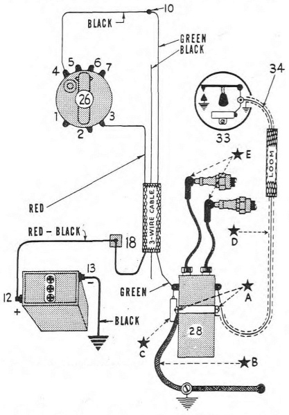
10—INSTRUMENT PANEL TERMINAL.
10—DASHBOARD TERMINAL.
12—BATTERY POSITIVE.
12—Positive Battery.
13—BATTERY NEGATIVE (GROUND).
13—BATTERY NEGATIVE (GND).
18—TERMINAL JUNCTION ON FRAME.
18—Terminal junction on frame.
26—IGNITION—LIGHT SWITCH.
26—IGNITION—LIGHT SWITCH.
28—SPARK COIL.
28—Ignition Coil.
33—CIRCUIT BREAKER.
33—Circuit Breaker.
34—COIL TO TIMER WIRE.
34—Coil to timer wire.
*A—RADIO BOND, COIL TO TIMER WIRE.
*A—RADIO BOND, COIL TO TIMER WIRE.
*B—RADIO BOND, COIL TO ENGINE.
*B—RADIO BOND, CONNECT TO ENGINE.
*C—NOISE SUPPRESSION CONDENSER.
*C—Noise Suppression Condenser.
*D—SHIELDED COIL TO TIMER WIRE.
*D—Shielded Coil to Timer Wire.
*E—SPARK PLUG SUPPRESSORS.
*E—Spark Plug Suppressors.
RA PD 315723
Figure 48—Ignition to Battery Wiring Diagram
RA PD 315723
Figure 48—Ignition to Battery Wiring Diagram
Section 18
Ignition System
| Paragraph | |
|---|---|
| Description | 82 |
| Spark plugs | 83 |
| Circuit breaker points | 84 |
| Condenser | 85 |
| Circuit breaker and timer assembly | 86 |
| Coil to timer wire | 87 |
| Adjust spark control | 88 |
| Spark coil | 89 |
82. DESCRIPTION.
a. The ignition system differs from that of the conventional automotive types in that it has no distributor. A circuit breaker alone is used. Both coil high‐tension winding ends lead directly to both spark plugs. Thus both plugs spark at the same time, one cylinder being on compression stroke while the other cylinder is on exhaust stroke.
a. The ignition system is different from traditional automotive types because it doesn’t have a distributor. It uses just a circuit breaker. The ends of the coil's high-tension winding go directly to both spark plugs. This way, both plugs spark at the same time, with one cylinder on the compression stroke and the other on the exhaust stroke.
83. SPARK PLUGS.
a. Defective spark plugs are indicated by engine missing, overheating, knocking excessively, and lacking normal power.
a. Faulty spark plugs are shown by the engine misfiring, overheating, making excessive knocking sounds, and lacking normal power.
b. Type. Spark plugs are medium heat range, manufacturer’s (H–D) No. 3.
b. Type. Spark plugs are medium heat range, manufacturer's (H–D) No. 3.
c. Cleaning. Do not take plugs apart for cleaning. Use the sandblast cleaner method.
c. Cleaning. Don’t take plugs apart to clean them. Use the sandblast cleaning method.
d. Point Adjustment. Bend electrode located in plug base to adjust point gap 0.025 inch to 0.030 inch.
d. Point Adjustment. Bend the electrode at the plug base to set the point gap between 0.025 inch and 0.030 inch.
e. Replacement. Use spark plug wrench (41–W–3334) to install plugs, using new gaskets. Never draw a cool plug up tight in a hot cylinder head, rather turn down snug and wait l/2 minute until plug base is warm: then tighten securely. CAUTION: Take care not to cross‐thread when installing spark plug.
e. Replacement. Use a spark plug wrench (41–W–3334) to install the plugs with new gaskets. Never tighten a cool plug in a hot cylinder head; instead, turn it down snug and wait for 30 seconds until the plug base is warm, then tighten it securely. CAUTION: Be careful not to cross-thread when installing the spark plug.
84. CIRCUIT BREAKER POINTS (fig. 49).
a. Circuit breaker lever is insulated from ground and connects to primary wire binding post by means of a “pig‐tail” wire. Stationary point is grounded to timer base and is movable in order to adjust circuit breaker points. Circuit breaker points that are burned or pitted should be renewed or dressed with a clean fine‐cut, contact point file. The file should not be used on other metals and should not be allowed to become greasy or dirty. CAUTION: Never use emery130 cloth to clean points. Contact surfaces, after considerable use, may not appear bright and smooth, but this is not necessarily an indication that they are not functioning satisfactorily.
a. The circuit breaker lever is insulated from the ground and connects to the primary wire binding post through a "pig-tail" wire. The stationary point is grounded to the timer base and can be moved to adjust the circuit breaker points. Circuit breaker points that are burned or pitted should be replaced or smoothed with a clean, fine-cut contact point file. The file should only be used on these specific components and must not get greasy or dirty. CAUTION: Never use emery130 cloth to clean points. After extensive use, contact surfaces may not look bright and smooth, but that doesn't necessarily mean they aren't working properly.
b. Remove Breaker Lever.
b. Remove circuit breaker lever.
(1) To disconnect condenser terminal, remove nut from end of condenser and remove gear‐toothed washer, plain washer, and the brass terminal strip. Do not remove fiber washer and plain washer located back of brass terminal strip on condenser terminal post.
(1) To disconnect the condenser terminal, take off the nut from the end of the condenser and remove the gear-toothed washer, plain washer, and the brass terminal strip. Do not take off the fiber washer and plain washer located behind the brass terminal strip on the condenser terminal post.

RA PD 310248
Figure 49—Circuit Breaker Points Removed
RA PD 310248
Figure 49—Circuit Breaker Points Removed
(2) Bend brass terminal strip down and remove binding nut which secures brass terminal strip and breaker lever “pig‐tail” to primary wire binding post.
(2) Bend the brass terminal strip down and take off the binding nut that secures the brass terminal strip and breaker lever “pig-tail” to the primary wire binding post.
(3) Compress breaker lever spring at end of lever, disengaging spring. CAUTION: Do not lose spring. Release and remove lever from insulated pivot post.
(3) Compress the spring at the end of the lever to disengage it. CAUTION: Don't lose the spring. Release and take the lever off the insulated pivot post.
c. Remove Adjustable Contact Point.
c. Take off Adjustable Contact Point.
(1) Remove the two lock screws and washer plate, securing adjustable contact point assembly to timer base. Point assembly is free to be lifted off lever pivot stud.
(1) Take off the two lock screws and the washer plate that hold the adjustable contact point assembly to the timer base. The point assembly can now be lifted off the lever pivot stud.
d. Install Adjustable Contact Point.
d. Install Adjustable Contact Point.
(1) Install contact point assembly, replacing washer plate and the two lock screws. Do not tighten lock screws until circuit breaker points are adjusted (step f below).
(1) Install the contact point assembly, replacing the washer plate and the two lock screws. Don’t tighten the lock screws until the circuit breaker points are adjusted (step f below).
e. Install Breaker Lever.
e. Install Breaker Handle.
(1) Install brass terminal strip on primary wire binding post.
(1) Install the brass terminal strip on the primary wire binding post.
(2) Connect end of brass terminal strip to condenser terminal post. Install flat washer, gear‐toothed washer, and nut.
(2) Connect the end of the brass terminal strip to the condenser terminal post. Install a flat washer, a gear-toothed washer, and a nut.
(3) Install breaker lever on pivot post insulated bearing.
(3) Install the breaker lever on the pivot post's insulated bearing.
(4) Install breaker lever spring. Make sure that ends of spring are retained correctly.
(4) Install the breaker lever spring. Ensure that the ends of the spring are secured properly.
(5) NOTE: Keep breaker lever cam very lightly greased.
(5) NOTE: Keep the breaker lever cam lightly greased.
f. Adjusting Circuit Breaker Points (fig. 51).
f. Adjusting Circuit Breaker Settings (__A_TAG_PLACEHOLDER_0__).
(1) Correct point gap is 0.022 inch. Circuit breaker point faces must seat squarely against each other. If bent, square up and aline by bending contact plate. Turn timer breaker cam until breaker lever fiber is located on highest point of cam.
(1) The correct gap between the points is 0.022 inch. The circuit breaker point faces must sit squarely against each other. If they're bent, straighten them out and align them by bending the contact plate. Rotate the timer breaker cam until the breaker lever fiber is positioned at the highest point of the cam.
(2) With the adjustable point lock screws loose, shift the adjustable point plate to obtain a 0.022–inch gap between the circuit breaker points. Measure gap with an accurate thickness gage before retightening lock screws, and again recheck point gap after tightening the lock screws. NOTE: Wrong circuit breaker point gap affects ignition timing.
(2) With the adjustable point lock screws loose, move the adjustable point plate to create a 0.022-inch gap between the circuit breaker points. Use a precise thickness gauge to measure the gap before tightening the lock screws, and then check the point gap again after tightening the screws. NOTE: An incorrect circuit breaker point gap impacts ignition timing.
85. CONDENSER.
a. The condenser is connected in parallel with the circuit breaker points, one of its terminals being grounded (for the adjustable point) to the timer base by means of the mounting screw, the other terminal making connection with the circuit breaker lever (for the lever point) by means of the lever “pig‐tail.”
a. The condenser is connected in parallel with the circuit breaker points, with one terminal grounded (for the adjustable point) to the timer base using the mounting screw, while the other terminal connects to the circuit breaker lever (for the lever point) through the lever "pig-tail."
b. Remove.
b. Delete.
(1) Unlatch circuit breaker cover retainer and remove cover.
(1) Unhook the circuit breaker cover retainer and take off the cover.
(2) Remove nut from end of condenser and remove gear‐toothed washer, plain washer, and the brass terminal strip. NOTE: A small plain washer and a large fiber washer are located behind brass terminal strip.
(2) Take off the nut from the end of the condenser and remove the gear-toothed washer, plain washer, and the brass terminal strip. NOTE: A small plain washer and a large fiber washer are positioned behind the brass terminal strip.
(3) Remove screw which secures condenser to timer base. Remove condenser.
(3) Take out the screw that holds the condenser to the timer base. Remove the condenser.

RA PD 310249
Figure 50—Circuit Breaker (Timer), Disassembled
RA PD 310249
Figure 50—Circuit Breaker (Timer), Disassembled
c. Install.
c. Install.
(1) Mount condenser on timer housing. Install lock washer and screw. Make sure small plain washer and large fiber washer are in place on condenser end terminal screw before connecting the brass terminal strip.
(1) Attach the condenser to the timer housing. Install the lock washer and screw. Ensure that the small plain washer and large fiber washer are positioned correctly on the condenser end terminal screw before connecting the brass terminal strip.
(2) Connect brass terminal strip to condenser. Replace plain washer, gear‐toothed washer and terminal nut.
(2) Connect the brass terminal strip to the condenser. Replace the plain washer, gear-toothed washer, and terminal nut.
(3) Install circuit breaker cover.
Install circuit breaker panel cover.
86. CIRCUIT BREAKER AND TIMER ASSEMBLY (figs. 50 and 51).
a. When the circuit breaker timer shaft and base assembly must be replaced due to excessive wear in timer shaft bearing, sheared worm gear pin, and/or worn or damaged worm gear, engine ignition must be retimed. Ignition timing for the V‐type twin engine is difficult and should be attempted only by experienced personnel.
a. When the circuit breaker timer shaft and base assembly needs to be replaced because of excessive wear in the timer shaft bearing, a sheared worm gear pin, and/or a worn or damaged worm gear, the engine's ignition must be retimed. Ignition timing for the V-type twin engine is challenging and should only be attempted by experienced personnel.
b. Remove (fig. 50). Before the timer shaft and base assembly can be removed, the circuit breaker timer head assembly must be removed. NOTE: If the timer head only, or timer wire, is to be replaced, it is not necessary to remove timer shaft and base assembly, and thus throw engine ignition out of time.
b. Remove (fig. 50). Before you can take out the timer shaft and base assembly, you need to remove the circuit breaker timer head assembly. NOTE: If you're only replacing the timer head or timer wire, you don’t need to remove the timer shaft and base assembly, which would throw the engine ignition off timing.
(1) Remove timer head cover.
Remove timer cover.
(2) Unlatch cover retainer ends from holes in the timer head and remove.
(2) Unhook the cover retainer ends from the holes in the timer head and take it off.
(3) Disconnect spark control wire at timer lever.
(3) Unplug the spark control wire from the timer lever.
(4) Lift the timer head assembly off base. The head seating tension (ground) spring (underneath shaft base) is also free, and can now be removed. NOTE: It is not necessary to disconnect timer to coil wire from timer head terminal post, unless head or wire is being replaced.
(4) Remove the timer head assembly from the base. The head seating tension (ground) spring (located underneath the shaft base) is now loose and can be taken out. NOTE: You don’t need to disconnect the timer to coil wire from the timer head terminal post unless you’re replacing the head or the wire.
(5) Remove the two timer base mounting screws and lock washers. It will be noted that one screw grounds the timer to coil wire shielding.
(5) Take out the two screws that mount the timer base and the lock washers. You'll notice that one of the screws grounds the timer to the coil wire shielding.
(6) Timer shaft and base assembly can now be lifted out of engine gear case cover. Take care not to damage or misplace base gasket.
(6) You can now lift the timer shaft and base assembly out of the engine gear case cover. Be careful not to damage or lose the base gasket.
c. Install Timer Shaft and Base Assembly and Timing Ignition (fig. 51). This calls for retiming engine ignition as follows: (NOTE: Circuit breaker cam turns in clockwise direction):
c. Install Timer Shaft and Base Assembly and Timing Ignition (fig. 51). This involves retiming the engine ignition as follows: (NOTE: The circuit breaker cam rotates in a clockwise direction):
(1) Unscrew and raise front cylinder inlet valve spring cover, using tappet wrench (41–W–3617).
(1) Unscrew and lift the front cylinder inlet valve spring cover with a tappet wrench (41–W–3617).
(2) Turn engine in direction in which it runs until valve tappet indicates front cylinder is on compression stroke (directly after front cylinder intake valve closes).
(2) Turn the engine in the direction it runs until the valve tappet shows that the front cylinder is on the compression stroke (right after the front cylinder intake valve closes).

A—FLYWHEEL TIMING MARK IN CRANKCASE INSPECTION HOLE.
A—FLYWHEEL TIMING MARK IN CRANKCASE INSPECTION HOLE.
B—COVER RETAINER.
B—COVER CLIP.
C—CIRCUIT BREAKER LEVER.
C—Circuit Breaker Switch.
D—CIRCUIT BREAKER CAM.
D—Circuit Breaker Cam.
E—CONDENSER.
E—CONDITIONER.
F—SPARK CONTROL WIRE HOUSING.
F—Spark control wire housing.
G—SPARK CONTROL WIRE.
G—Spark Control Wire.
H—SPARK LEVER QUADRANT.
H—Spark Lever Quadrant.
J—SPARK LEVER.
J—Spark Lever.
K—TIMER HEAD ADJUSTING BAND SCREW.
K—TIMER HEAD ADJUSTMENT SCREW.
L—TIMER HEAD ADJUSTING BAND.
L—TIMER HEAD ADJUSTMENT BAND.
M—MARK ON BREAKER CAM AND MARKS ON TIMER HEAD AND HAND INDICATING ORIGINAL FACTORY TIMING.
M—MARK ON BREAKER CAM AND MARKS ON TIMER HEAD AND HAND INDICATING ORIGINAL FACTORY TIMING.
N—CIRCUIT BREAKER POINTS.
N—Circuit Breaker Points.
O—ADJUSTABLE CONTACT POINT PLATE.
O—Adjustable contact point plate.
P—ADJUSTABLE CONTACT POINT LOCK SCREWS.
P—Adjustable contact point lock screws.
Q—CIRCUIT BREAKER LEVER PIVOT (INSULATED).
Q—Insulated circuit breaker lever pivot.
R—BREAKER LEVER SPRING.
R—Breaker lever spring.
RA PD 310281
Figure 51—Circuit Breaker Marks and Flywheel Mark Correctly Alined
RA PD 310281
Figure 51—Circuit Breaker Marks and Flywheel Mark Correctly Aligned
(3) Remove plug from timing inspection hole in left‐side crankcase.
(3) Take out the plug from the timing inspection hole in the left side of the crankcase.
(4) Continue turning engine slowly until flywheel timing mark is in center of inspection hole (fig. 51). Do not turn engine further.
(4) Keep turning the engine slowly until the flywheel timing mark is in the center of the inspection hole (fig. 51). Do not turn the engine any further.
(5) Install paper gasket and timer head tension (ground) spring on timer shaft base assembly. Make sure bent ends of tension spring are facing downward (away from timer base).
(5) Install the paper gasket and the timer head tension (ground) spring on the timer shaft base assembly. Ensure that the bent ends of the tension spring are pointing downwards (away from the timer base).
(6) Insert timer shaft and base assembly all the way down into place in timing gear case cover, trying to locate mark on small end135 of breaker cam in position shown in figure 51. Do not install base mounting screws as yet.
(6) Insert the timer shaft and base assembly all the way down into the timing gear case cover, making sure to align the mark on the small end135 of the breaker cam as shown in figure 51. Don't install the base mounting screws yet.
(7) Install timer head assembly so that spark control lever is within the advance and retard quadrant (fig. 51). NOTE: Do not install cover retainer until later.
(7) Install the timer head assembly so that the spark control lever is within the advance and retard quadrant (fig. 51). NOTE: Do not install the cover retainer until later.
(8) Fully advance spark lever (push inward toward engine) and observe how closely mark on breaker cam lines up with breaker lever fiber. If mark does not line up, lift timer base and turn shaft gear so its engagement with its driving gear is changed one tooth. Check again according to breaker cam mark and breaker lever fiber. Repeat this procedure until gear engagement is obtained which closely alines cam mark and breaker lever fiber.
(8) Push the spark lever fully in toward the engine and check how closely the mark on the breaker cam lines up with the breaker lever fiber. If the mark doesn’t align, lift the timer base and turn the shaft gear to change its engagement with the driving gear by one tooth. Check again according to the breaker cam mark and the breaker lever fiber. Repeat this process until the gear engagement is adjusted so that the cam mark and breaker lever fiber align closely.
(9) See that timer base is turned so that timer to coil wire is toward rear of engine.
(9) Make sure the timer base is rotated so that the timer to coil wire is facing the back of the engine.
(10) Install timer base screws and lock washers. Make sure that timer to coil wire shielding is grounded under head of screw farthest away from engine (fig. 52). Securely tighten screws.
(10) Install the timer base screws and lock washers. Ensure that the timer to coil wire shielding is grounded under the head of the screw that is farthest from the engine (fig. 52). Tighten the screws securely.
(11) Install timer head on base and secure with ground spring and cover retainer. Be sure ground spring is in its proper place so that when cover retainer ends are fitted through holes in the timer head, they will also fit into spring locating notches. It will be necessary to press ground spring upward under timer base to engage retainer ends in the spring notches. NOTE: If cover retainer ends do not engage ground spring notches, spring will have no tension and timer head will be loose on its base. Circuit breaker points and condenser are electrically grounded through timer base, and ground spring holds the head and base in close contact, thus assuring a good ground.
(11) Attach the timer head to the base and secure it with the ground spring and cover retainer. Make sure the ground spring is positioned correctly so that when the ends of the cover retainer are inserted into the holes in the timer head, they also fit into the spring locating notches. You’ll need to push the ground spring upward under the timer base to hook the retainer ends into the spring notches. NOTE: If the ends of the cover retainer don't fit into the ground spring notches, the spring won't have any tension, and the timer head will be loose on the base. The circuit breaker points and condenser are electrically grounded through the timer base, and the ground spring keeps the head and base in close contact, ensuring a solid ground.
(12) Connect spark control wire and timer lever and adjust (par. 88).
(12) Connect the spark control wire and the timer lever, then adjust (par. 88).
(13) Engine is now timed according to original factory setting, providing mark on side of timer head and hole in head adjusting band are still in alinement, and circuit breaker point gap is 0.022 inch. Even though all ignition timing marks are in perfect alinement, as outlined in the foregoing instructions, it is advisable to accurately check ignition timing (step d following).
(13) The engine is now timed to the original factory setting, as long as the mark on the side of the timer head and the hole in the adjusting band are still aligned, and the circuit breaker point gap is 0.022 inches. Even if all the ignition timing marks are perfectly aligned, as explained in the previous instructions, it's a good idea to double-check the ignition timing (step d below).
d. Recommended Recheck of Ignition Timing (fig. 51). Even though all ignition timing marks are in perfect alinement, as when engine was originally timed, ignition timing may change somewhat after engine has been in service for a while, due to normal wear and seating of the various moving parts that can affect ignition timing. Since accurate ignition timing is the first essential to good engine performance, it is advisable to check ignition timing on new vehicle after first 1,500 miles of service, and at each 2,000 miles thereafter.
d. Recommended Recheck of Ignition Timing (fig. 51). Even if all the ignition timing marks are perfectly aligned, just like when the engine was initially timed, the ignition timing can change a bit after the engine has been in use for some time due to normal wear and the settling of various moving parts that can impact ignition timing. Since getting the ignition timing right is crucial for good engine performance, it's a good idea to check the ignition timing on a new vehicle after the first 1,500 miles of use, and then every 2,000 miles after that.
(1) See that circuit breaker points are adjusted for correct gap of 0.022 inch (par. 84 f).
(1) Make sure the circuit breaker points are adjusted to a correct gap of 0.022 inch (par. 84 f).
(2) Advance timer lever fully (toward engine).
(2) Push the advance timer lever all the way forward (toward the engine).
(3) Turn engine in direction in which it runs until front cylinder is on compression stroke, and continue to turn it ahead slowly until narrow timer cam (the end with the timing mark), just starts to open the circuit breaker points.
(3) Turn the engine in the direction it runs until the front cylinder is on the compression stroke, and keep turning it slowly forward until the narrow timer cam (the end with the timing mark) just starts to open the circuit breaker points.

RA PD 318205
Figure 52—Shielding of Coil to Timer Wire Grounded on Base
RA PD 318205
Figure 52—Shielding of Coil to Timer Wire Grounded on Base
(4) An accurate test light check as to when points just start to break can be made, using the instrument panel red light for the purpose. Disconnect panel light wire from the oil pressure switch, attaching this wire to the insulated terminal post on timer head. Turn ignition and light switch on. As long as circuit breaker points are closed, lamp will remain lit; as points start to open, lamp will go out. NOTE: After making use of instrument panel red light for above purpose, reconnect wire to oil pressure switch.
(4) You can accurately check when the points just start to break by using the instrument panel's red light. Disconnect the panel light wire from the oil pressure switch and connect this wire to the insulated terminal post on the timer head. Turn on the ignition and light switch. As long as the circuit breaker points are closed, the lamp will stay lit; when the points start to open, the lamp will go out. NOTE: After using the instrument panel's red light for this purpose, reconnect the wire to the oil pressure switch.
(5) When exact position is found, where points just start to open, flywheel mark should be in the center of the inspection hole.
(5) When the exact position is found, where points just start to open, the flywheel mark should be in the center of the inspection hole.
(6) If flywheel mark is not in center of hole when points open, readjust ignition timing as necessary (slower or faster) by means of the timer head and band adjustment.
(6) If the flywheel mark isn't centered in the hole when the points open, readjust the ignition timing as needed (slower or faster) using the timer head and band adjustment.

RA PD 318203
Figure 53—Shielded Coil to Timer Wire Correctly Connected at Coil
RA PD 318203
Figure 53—Shielded Coil to Timer Wire Properly Connected at Coil
(7) To readjust timer head, loosen adjusting band screw and shift timer head in band. If flywheel timing mark shows forward of center in inspection hole, the timing is slow. To correct, shift timer head counterclockwise against rotation of breaker cam. If flywheel mark is to rear of center of inspection hole, timing is fast and timer head must be shifted with rotation (clockwise) of breaker cam, to correct timing.
(7) To adjust the timer head, loosen the adjusting band screw and move the timer head within the band. If the flywheel timing mark is positioned ahead of center in the inspection hole, the timing is slow. To fix this, turn the timer head counterclockwise against the direction of the breaker cam. If the flywheel mark is behind center in the inspection hole, the timing is fast, and the timer head must be adjusted clockwise in the direction of the breaker cam to correct the timing.
(8) With ignition timing correct, front cylinder piston is 9/32 inch before top dead center, on compression stroke, when circuit breaker points just start to open. At this point spark occurs, igniting front cylinder fuel charge.
(8) With the ignition timing set properly, the front cylinder piston is 9/32 inch before top dead center on the compression stroke when the circuit breaker points just begin to open. At this moment, the spark occurs, igniting the fuel charge in the front cylinder.
(9) Install flywheel inspection hole plug in left crankcase.
(9) Install the flywheel inspection hole plug in the left crankcase.
87. COIL TO TIMER WIRE (figs. 52 and 53).
a. Models provided with radio shielding are identified by “S” on either side of instrument panel. The coil to timer wire (low‐tension wire) on these models is shielded for radio noise suppression.
a. Models with radio shielding are marked with an “S” on either side of the instrument panel. The coil to timer wire (low-tension wire) in these models is shielded to reduce radio noise interference.
b. Remove.
b. Delete.
(1) Disconnect battery negative ground wire at frame connection.
(1) Disconnect the negative battery ground wire at the frame connection.
(2) Remove the two bolts which secure upper end of air cleaner bracket to frame tube. Swing air cleaner and bracket outward and forward to gain access to spark coil rear terminal.
(2) Take off the two bolts that hold the upper end of the air cleaner bracket to the frame tube. Swing the air cleaner and bracket outwards and forwards to access the rear terminal of the spark coil.
(3) Disconnect coil to timer wire terminal from coil rear connection. Disconnect wire shielding from coil rear ground connection.
(3) Disconnect the coil from the timer wire terminal at the back connection of the coil. Remove the wire shielding from the back ground connection of the coil.
(4) Refer to paragraph 86 b (1) to (4) for timer head removal.
(4) Refer to paragraph 86 b (1) to (4) for removing the timer head.
(5) Remove timer base mounting screw which secures wire shielding (fig. 52).
(5) Take off the timer base mounting screw that holds the wire shielding in place (fig. 52).
(6) Note position of coil to timer wire inside of timer head; then remove nut washer connecting wire to insulated contact stud.
(6) Take note of the coil's position relative to the timer wire inside the timer head; then remove the nut washer that connects the wire to the insulated contact stud.
(7) Work old wire and loom out of timer head hole and free from vehicle.
(7) Remove the old wire and loom from the timer head hole and detach it from the vehicle.
(8) On earlier models, the coil to timer wire was soldered to end of insulated stud. Removal of stud is necessary to remove this wire, or replace it with a shielded wire. Note location of stud insulations on inside and outside of timer head, for correct installation when reassembling.
(8) On earlier models, the wire from the coil to the timer was soldered to the end of the insulated stud. You have to take out the stud to remove this wire or replace it with a shielded wire. Make sure to note the location of the stud insulation on the inside and outside of the timer head for proper installation when putting it back together.
c. Install.
c. Install.
(1) Pass end of wire, shield terminal, and loom up through hole in timer base.
(1) Pass the end of the wire, shield terminal, and loom up through the hole in the timer base.
(2) Ground the wire shield terminal under head of timer base mounting screw (fig. 52).
(2) Attach the wire shield terminal under the head of the timer base mounting screw (fig. 52).
(3) Connect wire end terminal to insulated stud so that wire leads away from stud in direction shown (fig. 52).
(3) Connect the wire end terminal to the insulated stud so that the wire points away from the stud in the direction shown (fig. 52).
(4) Pass coil to timer wire up alongside and to rear of frame saddle post tube to reach rear of spark coil.
(4) Pass the coil to the timer wire up alongside and to the back of the frame saddle post tube to reach the back of the spark coil.
(5) Ground the wire shield terminal to coil rear ground connection (fig. 53).
(5) Connect the wire shield terminal to the ground connection at the back of the coil (fig. 53).
(6) Connect wire terminal to coil rear primary connection (fig. 53).
(6) Connect the wire terminal to the rear primary connection of the coil (fig. 53).
(7) Install timer head on base (par. 86 c (11)).
(7) Attach the timer head to the base (par. 86 c (11)).
(8) Connect spark control wire to timer lever and adjust (par. 88).
(8) Connect the spark control wire to the timer lever and adjust it (par. 88).
(9) Connect battery negative post wire to frame ground terminal.
(9) Connect the battery's negative post wire to the frame ground terminal.
(10) Swing air cleaner bracket back into place and install two bolts, washers, and nuts securing bracket to frame clips.
(10) Swing the air cleaner bracket back into position and install two bolts, washers, and nuts to secure the bracket to the frame clips.
(11) Replace timer cover and check engine for starting.
(11) Put the timer cover back on and check the engine to see if it starts.
88. ADJUST SPARK CONTROL.
a. Spark advance and retard is controlled by left handle bar grip. Spark lever operates within a quadrant mounted on engine. Spark must be fully advanced (lever inward toward engine) when handle bar grip is turned inward to full extent of its travel. When handle bar grip is turned outward, spark lever retards (lever outward away from engine).
a. The spark advance and retard are controlled by the left handlebar grip. The spark lever works within a quadrant attached to the engine. The spark must be fully advanced (lever pushed in toward the engine) when the handlebar grip is fully turned in. When the handlebar grip is turned out, the spark lever retards (lever pulled out away from the engine).
(1) With control wire in lever stud and clamp screw loose, turn left grip fully inward; then back it out just a little.
(1) With the control wire in the lever stud and the clamp screw loose, turn the left grip all the way inward; then pull it back out a bit.
(2) Shift spark lever inward toward engine as far as it will go; then tighten control wire clamp screw. Test by turning left grip fully inward and noting position of spark lever. It should be against inner side of quadrant (fig. 51). Retard spark and check position of lever within quadrant; it should be against outer side of quadrant.
(2) Push the spark lever in toward the engine as far as it can go; then tighten the control wire clamp screw. Test by turning the left grip all the way in and check the position of the spark lever. It should touch the inner side of the quadrant (fig. 51). Retard the spark and check the position of the lever within the quadrant; it should touch the outer side of the quadrant.
(3) Check final adjustment. Readjust full advance and retard timer lever positions as necessary when left grip is turned inward, and outward, respectively.
(3) Check the final adjustment. Readjust the full advance and retard timer lever positions as needed when the left grip is turned inward and outward, respectively.
89. SPARK COIL (fig. 54).
a. Spark coil high‐tension cables go directly to the spark plugs, no distributor being used. When the coil is faulty, it must be replaced, since internal repairs are not possible. The high‐tension cables can be replaced, however. Coil is provided with a condenser for radio noise suppression, and metal coil case is grounded to engine by bonding.
a. Spark coil high-tension cables connect directly to the spark plugs without using a distributor. If the coil is damaged, it needs to be replaced because internal repairs aren’t feasible. However, the high-tension cables can be replaced. The coil has a condenser for reducing radio noise, and the metal coil case is grounded to the engine through bonding.
b. Remove.
Remove.
(1) Disconnect battery negative ground wire from frame connection.
(1) Disconnect the negative ground wire of the battery from the frame connection.
(2) Free high‐tension cable ends (with radio noise suppressors) from spark plugs. Free front cylinder high‐tension cable from clip at upper engine frame mounting.
(2) Disconnect the high-tension cable ends (with radio noise suppressors) from the spark plugs. Release the front cylinder high-tension cable from the clip at the upper engine frame mounting.
(3) Loosen air intake hose connection at carburetor fitting.
(3) Loosen the connection of the air intake hose at the carburetor fitting.
(4) Remove two nuts, washers, and bolts securing upper end of air cleaner mounting bracket to frame clamps.
(4) Take off two nuts, washers, and bolts that hold the upper end of the air cleaner mounting bracket to the frame clamps.

RA PD 318204
Figure 54—Coil Front Connections Showing Radio Bonding and Noise
Suppression Condenser
RA PD 318204
Figure 54—Coil Front Connections Showing Radio Bonding and Noise Suppression Condenser
(5) Swing air cleaner and bracket assembly outward to gain access to coil rear terminals.
(5) Swing the air cleaner and bracket assembly outward to access the rear terminals of the coil.
(6) Disconnect coil to timer wire from coil rear terminal screw. Disconnect wire shielding from coil rear ground terminal (fig. 53).
(6) Disconnect the coil wire from the rear terminal screw of the timer. Disconnect the wire shielding from the rear ground terminal of the coil (fig. 53).
(7) Swing cleaner back and remove wire connections from coil front terminal screw (fig. 54).
(7) Swing the cleaner back and disconnect the wire connections from the front terminal screw on the coil (fig. 54).
(8) Disconnect radio bonding at coil front ground terminal (fig. 54).
(8) Unplug the radio bonding at the front ground terminal of the coil (fig. 54).
(9) Remove nuts and bolts which mount coil to bracket. Coil is now free for removal.
(9) Take off the nuts and bolts that attach the coil to the bracket. The coil is now free to be removed.
c. Install.
c. Install.
(1) Mount coil on frame bracket with high‐tension cables upward, and reinstall mounting bolts, lock washers, and nuts. Tighten nuts.
(1) Attach the coil to the frame bracket with the high-tension cables facing up, and then put the mounting bolts, lock washers, and nuts back in place. Tighten the nuts.
(2) Connect terminals of the two green wires to coil front terminal screw. Refer to wiring diagram, figure 48.
(2) Connect the ends of the two green wires to the front terminal screw of the coil. Refer to the wiring diagram, figure 48.
(3) Connect radio bonding to coil front ground terminal. Tighten nut securely.
(3) Connect the radio bonding to the front ground terminal of the coil. Tighten the nut securely.
(4) Connect coil to timer wire terminal to coil rear terminal screw. Connect wire shielding to coil rear ground terminal. Tighten nut securely.
(4) Connect the coil to the timer wire terminal and the coil rear terminal screw. Attach the wire shielding to the coil rear ground terminal. Tighten the nut securely.
(5) Swing air cleaner and bracket assembly back in place and install two bolts, lock washers, and nuts securing bracket to frame clamps. Tighten nuts securely.
(5) Swing the air cleaner and bracket assembly back into place and install two bolts, lock washers, and nuts to secure the bracket to the frame clamps. Tighten the nuts securely.
(6) Connect battery negative ground wire to frame connection.
(6) Connect the negative battery ground wire to the frame connection.
(7) Pass front cylinder high‐tension wire under tank, secure in cable clip at upper engine frame mounting, and attach cable end (radio noise suppressor) to front spark plug. Attach rear high‐tension cable end (radio noise suppressor) to rear spark plug.
(7) Pass the front cylinder high-tension wire under the tank, secure it in the cable clip at the upper engine frame mount, and connect the cable end (radio noise suppressor) to the front spark plug. Connect the end of the rear high-tension cable (radio noise suppressor) to the rear spark plug.
(8) Check wiring connections (fig. 48) and test coil by engine starting.
(8) Check the wiring connections (fig. 48) and test the coil by starting the engine.
Section 19
Generating System
| Paragraph | |
|---|---|
| Description | 90 |
| Clean commutator | 91 |
| Armature bearing special lubrication | 92 |
| Remove generator | 93 |
| Install generator | 94 |
| Cut‐out relay | 95 |

8—GENERATOR SIGNAL LIGHT
8—Generator Signal Light
12—BATTERY POSITIVE TERMINAL
12—Positive Battery Terminal
13—BATTERY NEGATIVE TERMINAL (GROUND)
13—Negative Battery Terminal (Ground)
14—“SWITCH” TERMINAL OF GENERATOR
14—“SWITCH” TERMINAL OF GENERATOR
15—“RELAY” TERMINAL OF GENERATOR
15—“RELAY” TERMINAL OF GENERATOR
18—FRONT JUNCTION TERMINAL
18—FRONT JUNCTION TERMINAL
26—IGNITION AND LIGHT SWITCH
26—Ignition and Light Switch
32—CUT‐OUT RELAY
32—Cut-Out Relay
*H—NOISE SUPPRESSION CONDENSER
*H—Noise-Canceling Condenser
RA PD 317200
Figure 55—Generator to Battery Wiring Diagram
RA PD 317200
Figure 55—Generator to Battery Wiring Diagram
90. DESCRIPTION (fig. 55).
a. The generator is shunt connected. The two field coils, regulating coil, and shunt coil are not connected in series in the conventional manner. The regulating field coil provides adequate current output (approx. 4 amperes) for daytime operation. The shunt field coil is controlled through the ignition and light switch to increase143 current output (approx. 8 amperes) when vehicle lights are in use. Generator uses the third (regulating) brush system of current regulation. A cut‐out relay serves as a magnetic switch in the generator‐battery circuit, also operating the instrument panel green signal light to indicate generator charge.
a. The generator is connected in a shunt configuration. The two field coils, the regulating coil, and the shunt coil aren’t connected in series like usual. The regulating field coil provides enough current output (about 4 amperes) for daytime operation. The shunt field coil is controlled through the ignition and light switch to boost143 current output (around 8 amperes) when the vehicle lights are on. The generator uses a third (regulating) brush system for current regulation. A cut-out relay acts as a magnetic switch in the generator-battery circuit, also operating the green signal light on the instrument panel to indicate generator charging.

RA PD 310259
Figure 56—Generator Cover Removed for Commutator Cleaning
RA PD 310259
Figure 56—Generator Cover Removed for Commutator Cleaning
91. CLEAN COMMUTATOR (fig. 56).
a. If battery is in good condition, cut‐out relay is functioning, and wiring connections are made according to diagram (fig. 55), yet generator does not charge or charge rate is low, proceed to clean the commutator.
a. If the battery is in good condition, the cut-out relay is working, and the wiring connections are made according to the diagram (fig. 55), but the generator doesn’t charge or the charge rate is low, proceed to clean the commutator.
(1) Remove left footboard, sidebar, and clutch foot pedal assembly, following procedure outlined under paragraph 102 a (1) to (6), to permit generator cover removal.
(1) Take off the left footboard, sidebar, and clutch foot pedal assembly, as described in paragraph 102 a (1) to (6), to allow for the removal of the generator cover.
(2) Remove the two end cover screws and pull end cover off generator.
(2) Take out the two end cover screws and pull the end cover off the generator.
(3) Clean armature commutator with No. 00 sandpaper until bright and clean. Blow out with air. CAUTION: Do not remove or disturb brushes in their holders. Never use emery cloth to clean the commutator.
(3) Clean the armature commutator with No. 00 sandpaper until it’s bright and clean. Blow it out with air. CAUTION: Do not remove or disturb the brushes in their holders. Never use emery cloth to clean the commutator.

RA PD 310260
Figure 57—Generator End Cover and Grease Retainer Removed
RA PD 310260
Figure 57—Generator End Cover and Grease Retainer Taken Off
(4) Temporarily install footboard assembly and operate engine, to observe whether or not generator is charging (green signal light goes off at above 20 mph). If cleaning commutator does not remedy generator charge, and/or commutator is badly worn, then generator must be replaced (par. 93). If cleaning of commutator remedied generator charge, reinstall generator end cover, and the footboard and clutch pedal assembly (par. 102 b).
(4) Temporarily attach the footboard assembly and run the engine to check if the generator is charging (the green signal light turns off at speeds over 20 mph). If cleaning the commutator doesn't fix the generator charge, and/or the commutator is excessively worn, the generator needs to be replaced (par. 93). If cleaning the commutator restores the generator charge, put the generator end cover back on, along with the footboard and clutch pedal assembly (par. 102 b).
92. ARMATURE BEARING SPECIAL LUBRICATION (fig. 57).
a. At the 6,000–mile second echelon preventive maintenance service period, the commutator end bearing must be hand‐packed. In performing this operation, care must be taken not to shift or move the generator third (regulating) brush, thus disturbing generator current regulation. Generator drive end bearing is adequately lubricated by oil circulating through engine.
a. During the 6,000-mile second echelon preventive maintenance service period, the commutator end bearing needs to be packed by hand. When doing this, it’s important to avoid shifting or moving the generator’s third (regulating) brush, as this could disrupt the generator's current regulation. The generator's drive end bearing receives enough lubrication from the oil circulating through the engine.
b. To Lubricate Commutator End Bearing.
b. To Lubricate the Commutator End Bearing.
(1) Remove left footboard, sidebar, and clutch pedal assembly, following procedure outlined in paragraph 102 a (1) to (6).
(1) Take off the left footboard, sidebar, and clutch pedal assembly following the steps described in paragraph 102 a (1) to (6).
(2) Remove the two end cover screws and pull end cover off generator.
(2) Take out the two end cover screws and slide the end cover off the generator.
(3) Remove two of the three screws which secure the outer grease retainer plate to end of generator (fig. 57).
(3) Remove two of the three screws that secure the outer grease retainer plate to the end of the generator (fig. 57).
(4) Loosen the other grease retainer plate screw slightly to permit shifting plate to one side.
(4) Loosen the other grease retainer plate screw a little to allow the shifting plate to move to one side.
(5) Pack ball bearing with general purpose grease No. 2, pressing lubricant into bearing with finger.
(5) Pack the ball bearing with general purpose grease No. 2, using your finger to press the lubricant into the bearing.
(6) Shift the outer grease retainer plate back into position. Install the two screws removed, and securely tighten all three screws.
(6) Move the outer grease retainer plate back into place. Reinstall the two screws you removed, and tighten all three screws securely.
(7) Install generator end cover and the two retaining screws.
(7) Install the generator end cover and the two retaining screws.
(8) Install left footboard, sidebar, and clutch foot pedal assembly, following procedure outlined in paragraph b.
(8) Install the left footboard, sidebar, and clutch foot pedal assembly, following the procedure outlined in paragraph b.
93. REMOVE GENERATOR (figs. 58 and 59).
a. Generator is gear driven through engine timing gear train. Generator can be removed and installed without removing timing gear case cover, or affecting alinement of timing gears.
a. The generator is connected through the engine's timing gear system. The generator can be taken out and put back in without needing to remove the timing gear case cover or disrupting the alignment of the timing gears.
b. Before replacing generator because of failure of instrument panel green signal light to indicate charge, check panel light wiring and bulb for good condition (par. 120).
b. Before replacing the generator due to the instrument panel's green signal light not indicating a charge, check the panel light wiring and bulb to ensure they are in good condition (par. 120).
c. When it has been determined that generator must be removed for replacement, proceed as follows:
c. When it's been decided that the generator needs to be replaced, proceed as follows:
(1) Disconnect wires from the two generator terminals marked SWITCH and RELAY.
(1) Unplug the wires from the two generator terminals labeled SWITCH and RELAY.
(2) Remove the two long screws, through timing gear case cover, that secure end of generator against gear case (fig. 58).
(2) Take out the two long screws from the timing gear case cover that hold the end of the generator against the gear case (fig. 58).
(3) Remove strap nut, lock washer, and curved washer from end of strap that clamps generator in its cradle on engine crankcase (fig. 59).
(3) Take off the strap nut, lock washer, and curved washer from the end of the strap that holds the generator in place on the engine crankcase (fig. 59).

RA PD 310261
Figure 58—Removing Generator End Mounting Screws
RA PD 310261
Figure 58—Taking Off the Generator End Mounting Screws

RA PD 310262
Figure 59—Removing Generator Strap Nut
RA PD 310262
Figure 59—Taking Off the Generator Strap Nut
(4) Lift strap high enough to permit raising generator so that oil slinger (on end of generator gear) will clear adjacent gear, and allow generator to be removed from engine. Be sure to observe and147 count number of paper shims between generator and cradle. Lay these shims aside to be used again when generator is reinstalled. Also, note location of hole in shims for oil drain. These shims were required in original assembly to adjust driving gears for proper mesh and, if left out, gears may mesh too deeply and “howl,” even though considerably worn. Unless a new generator gasket is available, to be used when generator is reinstalled, be careful not to damage the old one.
(4) Lift the strap high enough to raise the generator so that the oil slinger (on the end of the generator gear) clears the adjacent gear, allowing the generator to be removed from the engine. Be sure to observe and147 count the number of paper shims between the generator and cradle. Set these shims aside to reuse when reinstalling the generator. Also, take note of the hole location in the shims for the oil drain. These shims were necessary in the original assembly to adjust the driving gears for proper meshing, and if they are left out, the gears may mesh too deeply and "howl," even if they are considerably worn. Unless a new generator gasket is available for use when reinstalling the generator, be careful not to damage the old one.
94. INSTALL GENERATOR.
a. When installing generator, the important point to consider is correct shimming of generator in its cradle to provide correct mesh of driving gear with intermediate timing gear. Make sure same number of paper shims are used in reassembling as were found underneath generator when it was removed. After an engine has been run a considerable length of time and gears have worn to some extent, they have possibly developed sufficient lash or play to safely remove one or more of the original shims, and thus affect closer meshing and quieter operation. However, this should not be done unless timing gear case cover is removed so that gear mesh and lash can be carefully checked.
a. When installing the generator, it’s crucial to properly shim the generator in its cradle to ensure the driving gear meshes correctly with the intermediate timing gear. Make sure to use the same number of paper shims during reassembly as were found under the generator when it was taken out. After the engine has been running for a significant amount of time and the gears have worn down a bit, there may be enough play to safely remove one or more of the original shims. This can lead to better meshing and quieter operation. However, this should only be done if the timing gear case cover is removed so that the gear mesh and play can be checked carefully.
(1) Pass generator drive gear end through gear case hole, lifting generator so that oil slinger clears intermediate timing gear. Turn generator in its cradle so that end holes line up with long mounting screws which pass through gear case cover. Tighten mounting screws securely.
(1) Pass the generator drive gear end through the gear case hole, lifting the generator so that the oil slinger clears the intermediate timing gear. Rotate the generator in its cradle so that the end holes align with the long mounting screws that go through the gear case cover. Tighten the mounting screws securely.
(2) Install curved washer, lock washer, and nut on end of clamp strap; tighten nut securely.
(2) Put the curved washer, lock washer, and nut on the end of the clamp strap; tighten the nut firmly.
(3) Connect red‐black wire to generator terminal marked RELAY, and green wire to generator terminal marked SWITCH. Refer to wiring diagram (fig. 55).
(3) Connect the red-black wire to the generator terminal labeled RELAY, and the green wire to the generator terminal labeled SWITCH. Refer to the wiring diagram (fig. 55).
(4) Operate engine and check generator for current output, as well as check for gear noise. If shimming under generator is proper, generator and timing gears will run quietly. If necessary, readjust shimming until gears operate quietly.
(4) Start the engine and check the generator for current output, and also listen for any gear noise. If the shimming under the generator is correct, the generator and timing gears will operate quietly. If needed, adjust the shimming until the gears run quietly.
95. CUT‐OUT RELAY.
a. Operation of the instrument panel green signal light, indicating generator charge, is controlled by the cut‐out relay. Therefore, if relay is faulty the signal light will not operate properly, falsely indicating generator trouble. Rust around the contact points, burned points, and loss of armature spring tension are sources of most relay trouble. NOTE: Before condemning a relay because of failure of green signal light, make light test (par. 120).
a. The green signal light on the instrument panel that indicates generator charge is controlled by the cut-out relay. So, if the relay is malfunctioning, the signal light won’t work correctly, which can mistakenly suggest there’s an issue with the generator. Rust on the contact points, burned points, and loss of armature spring tension are the most common sources of relay problems. NOTE: Before deciding that a relay is faulty due to the failure of the green signal light, perform a light test (par. 120).
b. Correct adjustment of relay point gaps and tensioning of armature springs require use of precision electric meters and expert knowledge on the subject. A faulty relay, other than removing cover and cleaning with air, should be replaced. No adjustment of points should be attempted.
b. Properly adjusting relay point gaps and tensioning armature springs requires using precise electric meters and having expertise in the area. If a relay is faulty, aside from removing the cover and cleaning it with air, it should be replaced. No adjustments to the points should be made.
c. Remove.
c. Delete.
(1) Disconnect the three wires from relay terminal screws.
(1) Unplug the three wires from the relay terminal screws.
(2) Remove the two mounting screws and lock washers. Remove relay from engine base.
(2) Take out the two mounting screws and lock washers. Take the relay off the engine base.
d. Install.
d. Install.
(1) Mount relay on engine base with two screws and lock washers. Make sure that mounting is clean to make good electrical ground contact between relay and engine.
(1) Attach the relay to the engine base using two screws and lock washers. Ensure that the surface is clean to maintain a good electrical ground connection between the relay and the engine.
(2) Reconnect the three wire terminals to relay terminal screws. Follow wiring diagram, figure 55.
(2) Reconnect the three wire terminals to the relay terminal screws. Follow the wiring diagram in figure 55.
(3) Operate engine and observe action of relay, also action of instrument panel green signal light to indicate generator charge.
(3) Start the engine and watch how the relay works, along with the instrument panel's green signal light to show generator charging.
Section XX
Brake System
96. REAR WHEEL BRAKE (figs. 60, 61, and 62).
a. Linkage. Brake foot pedal on right side of vehicle is connected to bell crank (located on rear footboard support rod) by means of the front brake rod (nonadjustable). The bell crank is connected to rear brake operating lever by means of the rear brake rod with adjustable clevis end.
a. Linkage. The brake foot pedal on the right side of the vehicle is connected to the bell crank (located on the rear footboard support rod) through the front brake rod (which is non-adjustable). The bell crank is linked to the rear brake operating lever by the rear brake rod that has an adjustable clevis end.

b. Adjusting Rear Wheel Brake (fig. 60). If brake operating lever stands ahead of vertical position, excessive lining wear is indicated. Brake shoes must be replaced (steps c and d below). Normal free play of brake foot pedal before brake operation is 1 inch. After brake takes effect in vehicle operation, brake foot pedal should have 1–inch reserve travel before bottoming on footboard. If brake foot pedal operation does not come within these limits, adjust rear brake rod as follows:
b. Adjusting Rear Wheel Brake (fig. 60). If the brake operating lever is in front of the vertical position, it indicates that the lining is worn excessively. The brake shoes need to be replaced (see steps c and d below). The normal free play of the brake foot pedal before the brakes engage is 1 inch. Once the brakes are applied while the vehicle is in operation, there should be a 1-inch reserve travel on the brake foot pedal before it hits the footboard. If the operation of the brake foot pedal doesn't meet these standards, adjust the rear brake rod as follows:
(1) Remove cotter pin, plain washer, and clevis pin from end of rear brake rod clevis.
(1) Take out the cotter pin, plain washer, and clevis pin from the end of the rear brake rod clevis.
(2) Loosen clevis lock nut on brake rod.
(2) Loosen the clevis lock nut on the brake rod.
(3) Turn clevis onto (clockwise) brake rod to shorten rod and take up foot pedal free play.
(3) Turn the clevis on the brake rod clockwise to shorten the rod and reduce the free play in the foot pedal.
(4) Turn clevis off (counterclockwise) brake rod to lengthen rod and increase foot pedal free play.
(4) Rotate the clevis (counterclockwise) on the brake rod to lengthen it and increase the free play of the foot pedal.
(5) After making brake adjustment, spin rear wheel and make sure brake is not dragging. When correct brake adjustment is attained, install clevis pin in clevis and brake operating lever with plain washer, and retain with cotter pin. NOTE: Cotter pin must be in good condition.
(5) After adjusting the brakes, spin the rear wheel to ensure the brake isn't dragging. Once the correct brake adjustment is achieved, install the clevis pin in the clevis and the brake operating lever with a plain washer, and secure it with a cotter pin. NOTE: The cotter pin must be in good condition.

c. Remove Brake Shoes (fig. 61).
c. Remove Brake Pads (__A_TAG_PLACEHOLDER_0__).
(2) Remove brake drum and sprocket assembly. Brake shoes are now accessible. Do not remove side cover assembly from frame.
(2) Take off the brake drum and sprocket assembly. The brake shoes are now accessible. Do not take the side cover assembly off the frame.
(3) Disconnect brake rod clevis at brake operating lever.
(3) Unhook the brake rod clevis from the brake operating lever.
(4) Place end of large screwdriver blade between ends of brake shoes at pivot stud. Move brake‐operating lever forward to hold brake shoes in fully expanded position, and pry ends of shoes off pivot stud without removing brake shoe springs.
(4) Put the end of a large screwdriver blade between the ends of the brake shoes at the pivot stud. Push the brake-operating lever forward to keep the brake shoes in the fully expanded position, and pry the ends of the shoes off the pivot stud without taking off the brake shoe springs.
d. Install Brake Shoes. Observe that brake shoes are made for upper and lower positions and are not interchangeable. Recess in end of shoe for pivot stud head determines position of shoe in assembly.
d. Install Brake Shoes. Note that brake shoes are designed for upper and lower positions and cannot be swapped. The recess at the end of the shoe for the pivot stud head determines the shoe's position in the assembly.
(1) Engage ends of springs in shoe assembly holes from the inside before installing shoes on side cover (fig. 61).
(1) Connect the ends of the springs to the shoe assembly holes from the inside before putting the shoes on the side cover (fig. 61).
(2) With brake shoes and springs assembled, install so that ends of shoes will slip over pivot stud and shaft‐operating cam.
(2) With the brake shoes and springs put together, install them so that the ends of the shoes fit over the pivot stud and the shaft-operating cam.
(3) Connect brake rod clevis to brake operating lever.
(3) Attach the brake rod clevis to the brake operating lever.
(4) Install brake drum and sprocket assembly. Lock brake to hold drum in place while installing wheel (fig. 84).
(4) Install the brake drum and sprocket assembly. Lock the brake to hold the drum in place while you install the wheel (fig. 84).
(5) Install rear wheel (par. 127). NOTE: If rear chain is in need of adjustment, it should be done at this time.
(5) Install the rear wheel (par. 127). NOTE: If the rear chain needs adjustment, it should be done now.
(6) To equalize brake shoes, loosen nut on brake shoe adjustable pivot stud (on outside of brake side plate), and while applying pressure on brake foot pedal (to “center” the brake shoes within the drum), retighten the pivot stud nut.
(6) To balance the brake shoes, loosen the nut on the adjustable pivot stud of the brake shoe (located on the outside of the brake side plate), and while pressing down on the brake foot pedal (to “center” the brake shoes within the drum), re-tighten the pivot stud nut.
(7) After new or relined shoes have been installed, check foot pedal for free play (step b above).
(7) After new or relined shoes have been installed, check the foot pedal for free play (step b above).
97. FRONT WHEEL BRAKE (fig. 62).
a. Linkage (control). Handle bar hand lever control wire which operates front wheel brake can be adjusted and or replaced. Keep brake control wire lubricated (through oiler in housing and at ends of housing) with engine oil.
a. Linkage (control). The handlebar hand lever control wire that operates the front wheel brake can be adjusted or replaced. Keep the brake control wire lubricated (through the oiler in the housing and at the ends of the housing) with engine oil.
b. Remove Control Wire. Remove control wire clamp nut from brake lever clevis, and free lower end of control wire from clevis.
b. Remove Control Wire. Take off the control wire clamp nut from the brake lever clevis and detach the lower end of the control wire from the clevis.
(1) Remove cotter pin and flat washer from hollow pin, permitting hollow pin to be pulled out of hand lever. Control wire can now be pulled out of housing through the hole in hand lever.
(1) Take off the cotter pin and flat washer from the hollow pin, allowing the hollow pin to be removed from the hand lever. Now you can pull the control wire out of the housing through the hole in the hand lever.
c. Install Control Wire. Apply grease or engine oil to new control wire and insert, through hand lever, into control wire housing. Use caution when inserting a new control wire into housing, to prevent wire end from fraying. A frayed wire with loose end strands will not feed through the housing.
c. Install Control Wire. Apply grease or engine oil to the new control wire and insert it, through the hand lever, into the control wire housing. Be careful when inserting a new control wire into the housing to avoid the wire end from fraying. A frayed wire with loose strands at the end won’t feed through the housing.
(1) With control wire in housing, insert hand lever hollow pin so that narrow slot straddles control wire: then fit flat washer over end of hollow pin, retaining both with cotter pin.
(1) With the control wire in the housing, insert the hand lever hollow pin so that the narrow slot straddles the control wire; then fit the flat washer over the end of the hollow pin, securing both with a cotter pin.
(2) Insert lower end of control wire through clamp nut, then through clevis and back through clamp nut again. Grasp end of wire with pliers and pull until all slack is taken up. Then, while pulling wire snug, tighten clamp nut securely. Cut off excess wire.
(2) Insert the lower end of the control wire through the clamp nut, then through the clevis and back through the clamp nut again. Hold the end of the wire with pliers and pull until all the slack is removed. Then, while keeping the wire tight, securely tighten the clamp nut. Cut off any excess wire.
(3) Adjust brake control (refer to step d below).
(3) Adjust the brake control (see step d below).

RA PD 310274
Figure 62—Front Brake Control and Adjusting Members
RA PD 310274
Figure 62—Front Brake Control and Adjusting Parts
d. Adjusting Front Wheel Brake. End of brake hand lever must move freely about ¼ of its travel before meeting resistance of brake operation.
d. Adjusting Front Wheel Brake. The end of the brake hand lever should move freely about ¼ of its travel before feeling any resistance from the brake operation.
(1) Loosen adjusting sleeve lock nut and turn adjusting sleeve as necessary to attain correct free movement of hand lever.
(1) Unscrew the lock nut on the adjusting sleeve and rotate the adjusting sleeve as needed to achieve the proper free movement of the hand lever.
(2) After correct hand lever adjustment is made, tighten adjusting sleeve lock nut.
(2) After properly adjusting the hand lever, tighten the adjusting sleeve lock nut.
e. Remove Brake Shoes.
e. Take Off Brake Shoes.
(1) Remove front wheel (par. 125). After front wheel is removed, brake side cover and shoe assembly is accessible for shoe replacement.
(1) Take off the front wheel (par. 125). Once the front wheel is off, the brake side cover and shoe assembly can be accessed for shoe replacement.
(2) Remove brake shoes. Brake shoes and springs can be pried off pivot stud and freed from operating cam without removing springs.
(2) Take off the brake shoes. The brake shoes and springs can be pried off the pivot stud and released from the operating cam without having to remove the springs.
f. Install Brake Shoes. Observe that brake shoes are made for upper and lower positions and are not interchangeable. Recess in end of shoe for pivot stud head determines position of shoe in assembly.
f. Install Brake Shoes. Note that brake shoes are designed for upper and lower positions and cannot be swapped. The recess at the end of the shoe for the pivot stud head determines where the shoe belongs in the assembly.
(1) Engage ends of springs in shoe holes from the inside before installing shoes in brake side plate.
(1) Connect the ends of the springs to the shoe holes from the inside before putting the shoes into the brake side plate.
(2) With shoes and springs assembled, install the shoes so that ends of shoes will slip over pivot stud and shaft operating cam.
(2) With the shoes and springs put together, install the shoes so that the ends of the shoes fit over the pivot stud and the shaft operating the cam.
(3) Install front wheel and brake assembly (par. 125).
(3) Install the front wheel and brake assembly (par. 125).
(4) Loosen nut on brake shoe adjustable pivot stud and while applying pressure on brake hand lever, retighten pivot stud nut. This is to center brake shoes within the brake drum.
(4) Loosen the nut on the adjustable pivot stud of the brake shoe, and while pulling the brake hand lever, retighten the pivot stud nut. This is to align the brake shoes within the brake drum.
(5) After new or relined shoes have been installed, check brake hand lever and, if necessary, adjust the control wire (step d above).
(5) After new or re-soled shoes have been installed, check the brake hand lever and, if needed, adjust the control wire (see step d above).
Section 21
Steering Control
98. FORKS (figs. 63 and 64).
a. Either the spring fork can be removed and replaced, or the complete fork assembly (spring fork and rigid) can be replaced.
a. You can either remove and replace the spring fork, or you can replace the entire fork assembly (spring fork and rigid).
b. Remove Spring Fork (fig. 63).
b. Remove Spring Fork (__A_TAG_PLACEHOLDER_0__).
(1) Support vehicle on rear stand.
(1) Support the vehicle on a rear stand.
(2) Remove the fork spring rod lock nuts (acorn‐type).
(2) Take off the lock nuts for the fork spring rod (acorn-type).
(3) Sit on front mudguard, or otherwise provide weight, to compress fork cushion (lower) springs. The spring rod large nuts can then be easily removed, freeing the upper recoil and upper bumper springs for removal.
(3) Sit on the front mudguard, or add weight in some way, to compress the lower fork cushion springs. The large nuts on the spring rod can then be easily removed, allowing you to take out the upper recoil and upper bumper springs.
(6) Remove spring fork right and left side rocker plate studs. NOTE: Leave rigid fork rocker studs, with rockers, attached.
(6) Take off the spring fork studs on the right and left side of the rocker plate. NOTE: Keep the rigid fork rocker studs, along with the rockers, attached.
(7) Remove spring fork from vehicle.
(7) Take the spring fork off the vehicle.
c. Install Spring Fork.
c. Install Spring Fork.
(1) Place buffer springs and lower cushion springs on fork rods. Apply grease to rods. Pass fork rods up through rigid fork bracket. Bind lower end of spring fork to lower end of rigid fork with a strap or piece of heavy wire (fig. 64), to prevent forks from separating while compressing cushion springs.
(1) Put buffer springs and lower cushion springs on the fork rods. Apply grease to the rods. Slide the fork rods up through the rigid fork bracket. Secure the lower end of the spring fork to the lower end of the rigid fork with a strap or a piece of heavy wire (fig. 64), to keep the forks from separating while compressing the cushion springs.
(2) Install two bolts in the rigid fork brackets which mount the mudguard; then place a rod about 8 inches long on the brackets to provide a pry base for the leverage bar when compressing cushion springs (fig. 64). With a leverage bar about 18 inches long, anchored on top of the pry base rod and under the spring fork, lift upward to compress cushion springs sufficiently to install one of the rocker plates. Then install the other rocker plate (fig. 64). NOTE: Left side spring fork rocker plate stud has a button end which fits into notch in brake stabilizer plate.
(2) Install two bolts in the rigid fork brackets that hold the mudguard; then place a rod about 8 inches long on the brackets to create a pry base for the leverage bar when compressing cushion springs (fig. 64). Using a leverage bar that's about 18 inches long, positioned on top of the pry base rod and under the spring fork, lift upward to compress the cushion springs enough to install one of the rocker plates. After that, install the other rocker plate (fig. 64). NOTE: The left side spring fork rocker plate stud has a button end that fits into the notch in the brake stabilizer plate.
(3) Install mudguard (par. 104).
Install fender (par. __A_TAG_PLACEHOLDER_0__).
(5) Install the two spring rod bushings. Install upper bumper springs and upper recoil springs on the fork rods, applying grease to rods.
(5) Install the two spring rod bushings. Put the upper bumper springs and upper recoil springs on the fork rods, applying grease to the rods.
(6) Remove blocks from under vehicle.
(6) Take the blocks out from under the vehicle.
(7) Sit on mudguard to compress fork cushion (lower) springs. Tighten the two large spring rod nuts sufficiently to provide full thread for the spring rod lock nuts (acorn‐type). Install spring rod lock nuts and tighten.
(7) Sit on the mudguard to compress the lower fork cushion springs. Tighten the two large spring rod nuts enough to provide full thread for the spring rod lock nuts (acorn-type). Install the spring rod lock nuts and tighten them.
(8) See that all nuts, bolts, and screws securing lamp bracket, mudguard, scabbard carrier, and ammunition carrier are tightened securely.
(8) Make sure all nuts, bolts, and screws holding the lamp bracket, mudguard, scabbard carrier, and ammunition carrier are tightened securely.
(9) Check front wheel brake for operation.
(9) Check the front wheel brake to make sure it works.
d. Remove Upper Recoil Springs and/or Upper Bumper Springs.
d. Remove Upper Recoil Springs and/or Upper Bumper Springs.
(1) Support vehicle on rear stand. Remove the fork spring rod lock nuts (acorn‐type).
(1) Support the vehicle on a rear stand. Take off the lock nuts for the fork spring rod (acorn-type).
(2) Sit on front mudguard, or otherwise provide weight, to compress fork cushion (lower) springs. The spring rod large nuts can then be easily removed, freeing the upper recoil and upper bumper springs for removal.
(2) Sit on the front mudguard, or add weight in another way, to compress the lower fork cushion springs. You can then easily remove the large nuts on the spring rod, which will free up the upper recoil and upper bumper springs for removal.
e. Install Upper Recoil Springs and/or Upper Bumper Springs.
e. Install Upper Recoil Springs and/or Upper Bumper Springs.
(1) Apply grease to fork spring rods and install upper bumper springs.
(1) Put grease on the fork spring rods and install the upper bumper springs.
(2) Install upper recoil springs over bumper springs on fork spring rods.
(2) Install the upper recoil springs over the bumper springs on the fork spring rods.
(3) Sit on front mudguard to compress cushion (lower) springs sufficiently to start on spring rod large nuts.
(3) Sit on the front mudguard to compress the cushion (lower) springs enough to begin working on the large nuts of the spring rod.
(4) Tighten both spring rod large nuts. Install and tighten the two spring rod (acorn‐type) lock nuts.
(4) Tighten both large nuts on the spring rod. Install and tighten the two lock nuts for the spring rod (acorn-type).
f. Remove and Install Lower Cushion Springs and/or Lower Buffer Springs. This operation calls for same procedure followed in removing and installing spring fork (steps b and c above).
f. Remove and Install Lower Cushion Springs and/or Lower Buffer Springs. This task requires following the same steps used for removing and installing the spring fork (see steps b and c above).
g. Remove Complete Fork Assembly.
g. Take off Complete Fork Assembly.

RA PD 315728
Figure 63—Spring Fork Disassembled
RA PD 315728
Figure 63—Spring Fork Taken Apart
A—UPPER (RECOIL) SPRINGS
A—Upper (Recoil) Springs
B—UPPER BUMPER SPRINGS
B—UPPER BUMPER SPRINGS
C—SPRING ROD LOCK NUTS (ACORN‐TYPE)
C—Spring Rod Lock Nuts (Acorn-Type)
D—SPRING ROD BUSHINGS
D—Spring rod bushings
E—LARGE SPRING ROD NUTS
E—Large spring rod nuts
F—LOWER CUSHION SPRINGS
F—Cushion Springs
G—SPRING RODS
G—Spring Rods
H—LOWER BUFFER SPRINGS
H—Lower Buffer Springs
J—SPRING FORK ASSEMBLY
J—Spring Fork Assembly
K—ROCKER PLATE STUD NUTS AND LOCKS
K—ROCKER PLATE STUD NUTS AND LOCKS
L—RIGHT SIDE ROCKER PLATE STUD AND WASHER
L—RIGHT SIDE ROCKER PLATE STUD AND WASHER
M—LEFT SIDE ROCKER PLATE STUD (HAS BUTTON END) AND WASHER
M—LEFT SIDE ROCKER PLATE STUD (HAS BUTTON END) AND WASHER
N—AMMUNITION BOX CARRIER MOUNTING BOLT, WASHERS AND NUT
N—AMMUNITION BOX CARRIER MOUNTING BOLT, WASHERS AND NUT
O—HEADLIGHT BRACKET AND MUDGUARD BOLT, WASHER AND NUT (LEFT SIDE)
O—HEADLIGHT BRACKET AND MUDGUARD BOLT, WASHER AND NUT (LEFT SIDE)
P—FRONT AXLE, CASTLE NUT AND COTTER PIN
P—FRONT AXLE, CASTLE NUT AND COTTER PIN
Q—SCABBARD CARRIER MOUNTING BOLT, WASHERS AND NUT
Q—SCABBARD CARRIER MOUNTING BOLT, WASHERS, AND NUT
R—HEADLIGHT BRACKET AND MUDGUARD BOLT, MARKER LIGHT GABLE CLIP, WASHER AND NUT (RIGHT SIDE)
R—HEADLIGHT BRACKET AND MUDGUARD BOLT, MARKER LIGHT GABLE CLIP, WASHER AND NUT (RIGHT SIDE)
S—BRAKE SHACKLE BOLT, LOCK AND NUT
S—BRAKE SHACKLE BOLT, LOCK, AND NUT
T—BRAKE AND SIDE COVER ASSEMBLY
T—Brake and Side Cover Assembly
U—MUDGUARD BRACKET MOUNTING LOCK, WASHER AND NUTS (RIGHT SIDE)
U—MUDGUARD BRACKET MOUNTING LOCK, WASHER AND NUTS (RIGHT SIDE)
V—MUDGUARD AND RIGID FORK MOUNTING SCREWS, WASHERS AND NUTS
V—MUDGUARD AND RIGID FORK MOUNTING SCREWS, WASHERS AND NUTS
W—MUDGUARD BRACKET MOUNTING LOCK, WASHER AND NUTS (LEFT SIDE)
W—MUDGUARD BRACKET MOUNTING LOCK, WASHER AND NUTS (LEFT SIDE)
X—NOTCHES IN MUDGUARD BRACKETS FOR SPECIAL LOCKS
X—NOTCHES IN MUDGUARD BRACKETS FOR SPECIAL LOCKS
RA PD 3157288
Legend for Figure 63—Spring Fork Disassembled
RA PD 3157288
Legend for Figure 63—Spring Fork Disassembled
(5) Remove front mudguard, after removing nuts and locks from rear rocker plate studs, two screws and nuts securing mudguard to rigid fork, and the two bolts mounting headlight bracket to mudguard. NOTE: Front mudguard blackout light wire connects to158 ignition and light switch and care must be exercised not to break this wire if it is not disconnected from the switch.
(5) Take off the front mudguard after unscrewing the nuts and locks from the rear rocker plate studs, as well as the two screws and nuts that hold the mudguard to the rigid fork, and the two bolts that attach the headlight bracket to the mudguard. NOTE: The front mudguard blackout light wire connects to158 ignition and light switch, so be careful not to break this wire if it's not disconnected from the switch.
(6) Disconnect battery negative ground wire at frame connection. Remove blackout light (par. 114). Remove headlight, horn, and bracket assembly as one unit.
(6) Disconnect the negative battery ground wire at the frame connection. Remove the blackout light (par. 114). Take off the headlight, horn, and bracket assembly as one unit.
(7) Remove handle bar brake fittings and brake control wire housing from side of fork. Remove handle bars after removing handle bar bracket lock nut and cone lock plate. It is not necessary to disconnect spark and throttle control wire housings from frame. Unscrew fork upper adjusting cone from fork stem, freeing fork assembly to be removed from frame head. NOTE: Steering head ball bearings are loose (not in retainers) in upper and lower frame head bearing cups. Take care not to lose balls.
(7) Take off the handlebar brake fittings and brake control wire housing from the side of the fork. Remove the handlebars after taking off the handlebar bracket lock nut and cone lock plate. You don’t need to disconnect the spark and throttle control wire housings from the frame. Unscrew the upper adjusting cone from the fork stem to free the fork assembly for removal from the frame head. NOTE: The steering head ball bearings are loose (not in retainers) in the upper and lower frame head bearing cups. Be careful not to lose any balls.
h. Install Fork Assembly. With vehicle on rear stand, and front end up by blocking under frame loop or skid plate, proceed with installing fork assembly, as follows:
h. Install Fork Assembly. With the vehicle on a rear stand and the front end elevated by blocking under the frame loop or skid plate, proceed to install the fork assembly as follows:
(1) Thoroughly clean upper and lower frame head bearing cups and pack with general purpose grease No. 2, installing fifteen 5⁄16–inch ball bearings in each cup. Work grease thoroughly in between balls.
(1) Completely clean the upper and lower frame head bearing cups and fill them with general purpose grease No. 2, putting in fifteen 5⁄16–inch ball bearings in each cup. Make sure to work the grease thoroughly between the balls.
(2) See that lower fork stem cone is clean and in place, pass fork stem up through frame head, turning on upper adjusting cone. Do not try to adjust bearing cone as yet.
(2) Make sure that the lower fork stem cone is clean and properly seated, then push the fork stem up through the frame head while turning the upper adjusting cone. Don't try to adjust the bearing cone just yet.
(3) Install handle bars by locating mounting bracket on ends of fork sides and center stem, making sure that spark and throttle control wire housings are in place.
(3) Install the handlebars by finding the mounting bracket at the ends of the fork sides and the center stem, ensuring that the spark and throttle control wire housings are positioned correctly.
(4) Adjust upper fork stem adjusting cone so that there is no perceptible shake in head bearings when handle bars are worked up and down, and fork does not bind when turned to right and left extremes.
(4) Adjust the upper fork stem adjusting cone so that there is no noticeable shake in the head bearings when the handlebars are moved up and down, and the fork doesn’t stick when turned to the far right and left.
(5) Install cone lock plate by engaging pin in one of the cone notches.
(5) Install the cone lock plate by fitting the pin into one of the cone notches.
(6) Install lock nut on stem and tighten securely. NOTE: Check head bearing play, as tightening lock nut sometimes makes head bearing too tight. Readjust if necessary.
(6) Install the lock nut on the stem and tighten it securely. NOTE: Check for play in the head bearing, as tightening the lock nut can sometimes make the head bearing too tight. Readjust if needed.
(7) Attach handle bar brake fittings and brake control wire housing to side of fork.
(7) Attach the handlebar brake fittings and brake control wire housing to the side of the fork.

RA PD 310266
Figure 64—Compressing Cushion Springs for Spring
Fork Assembly
RA PD 310266
Figure 64—Compressing Cushion Springs for Spring Fork Assembly
(10) Install front mudguard. Attach two screws, washers, and nuts for rigid fork mounting and two bolts, washers, and nuts for160 headlight bracket mounting. Fit right and left mudguard brace clip locks to right and left side rocker plate studs respectively. Do not put on nuts until after installing ammunition box carrier and scabbard carrier.
(10) Install the front mudguard. Use two screws, washers, and nuts for mounting the rigid fork, and two bolts, washers, and nuts for the headlight bracket mounting. Attach the right and left mudguard brace clip locks to the right and left side rocker plate studs, respectively. Do not put on the nuts until after installing the ammunition box carrier and scabbard carrier.
(12) Install scabbard carrier and ammunition box carrier (par. 103).
(12) Install the scabbard carrier and the ammunition box carrier (par. 103).
(13) Check lights, horn, spark control, throttle control, front brake control, steering damper control, and steering head bearing for freedom without binding.
(13) Check the lights, horn, spark control, throttle control, front brake control, steering damper control, and steering head bearing to ensure they move freely without any binding.
i. Remove Rocker Plate Studs. Studs and/or rocker plates can be removed and installed in the same operation. In removing and installing studs, remove only one fork rocker plate at a time, leaving the other plate attached to opposite side fork ends to hold fork springs in compressed position. This will eliminate necessity of compressing fork springs to fit rocker plates on studs.
i. Remove Rocker Plate Studs. You can take off and put on studs and/or rocker plates in the same process. When removing and installing studs, only remove one fork rocker plate at a time, keeping the other plate attached to the opposite side fork ends to hold the fork springs in a compressed position. This will avoid the need to compress the fork springs to fit the rocker plates onto the studs.
(2) Remove nuts and locks from rocker plate studs on right side of vehicle. This releases gun scabbard carrier and mudguard stay clip. NOTE: Remove the large nut which secures the long stud to rigid fork.
(2) Take off the nuts and locks from the rocker plate studs on the right side of the vehicle. This will free the gun scabbard carrier and the mudguard stay clip. NOTE: Take off the large nut that secures the long stud to the rigid fork.
(3) Drive out studs from fork ends, releasing rocker plate.
(3) Remove the studs from the ends of the fork to release the rocker plate.
(4) Install studs and rocker plate before removing studs from left side of vehicle.
(4) Install studs and the rocker plate before taking out studs from the left side of the vehicle.
j. Install Rocker Plate Studs. Apply grease to studs and insert in rocker plate, then install large flat washers on studs before mounting this assembly on fork ends. Make sure that short stud is in front position, and that long stud is in rear position for the rigid fork.
j. Install Rocker Plate Studs. Apply grease to the studs and insert them into the rocker plate. Then, place large flat washers on the studs before mounting this assembly onto the fork ends. Ensure that the short stud is in the front position and that the long stud is in the rear position for the rigid fork.
(1) Drift studs (with plate assembly) into fork end holes from the inside.
(1) Slide the drift studs (with plate assembly) into the fork end holes from the inside.
(2) Install special nut lock (with half round hole) on front stud and turn stud as necessary to make lock “cup” over end of fork. Install and tighten stud nut and bend up end of lock for security. Place lock washer over long stud and install thick nut, securely tightening it.
(2) Install the special nut lock (with a half-round hole) on the front stud and adjust the stud as needed to fit the lock "cup" over the end of the fork. Install and tighten the stud nut, then bend up the end of the lock for security. Place the lock washer over the long stud and install the thick nut, tightening it securely.
(3) Attach end of gun scabbard carrier and mudguard brace clip with special lock to long stud, replacing washer and nut.
(3) Attach the end of the gun scabbard carrier and the mudguard brace clip with the special lock to the long stud, replacing the washer and nut.
(4) After right side rocker plate and/or studs have been installed, remove and install studs and/or plate on left side of vehicle following same step‐by‐step procedure as above. The exceptions will be ammunition box carrier instead of scabbard carrier; also, the left side front stud is special, having a “button” end.
(4) After installing the right side rocker plate and/or studs, remove and install the studs and/or plate on the left side of the vehicle using the same step-by-step procedure as above. The exceptions are the ammunition box carrier instead of the scabbard carrier; also, the left side front stud is special, with a “button” end.

99. STEERING DAMPER (fig. 65).
a. Remove (fig. 65).
a. Delete (__A_TAG_PLACEHOLDER_0__).
(3) Remove lock nut from steering damper rod, then remove upper end parts in the following order: adjusting nut, keyed steel washer, fiber washer, operating lever, and actuating sleeve. This entire assembly is located in the central part of the handle bar mounting bracket.
(3) Take off the lock nut from the steering damper rod, then take out the upper end parts in this order: adjusting nut, keyed steel washer, fiber washer, operating lever, and actuating sleeve. This whole assembly is found in the middle section of the handlebar mounting bracket.
(4) Steering damper rod, cushion spring, pressure disk, fiber disk, and steel disk assembly can now be withdrawn (downward) from fork stem hole.
(4) The steering damper rod, cushion spring, pressure disk, fiber disk, and steel disk assembly can now be removed (downward) from the fork stem hole.
b. Install (fig. 65). Before installing steering damper, make sure that the parts are in correct order on the lower end of the rod before passing rod up through hole in fork stem. Check parts and order of assembly.
b. Install (fig. 65). Before installing the steering damper, ensure that the parts are arranged correctly at the lower end of the rod before passing the rod up through the hole in the fork stem. Verify the parts and the order of assembly.
(1) Assemble parts on rod end (fig. 65), making sure that the bent down lip of the steel pressure disk engages with notch in end of the rod lock plate.
(1) Put together the parts on the rod end (fig. 65), ensuring that the bent-down edge of the steel pressure disk fits into the notch at the end of the rod lock plate.
(2) Pass rod with its lower end assembly up through hole in fork stem, turning steel pressure disk to front position so that “bent‐up” lip engages with notch in front side of rigid fork crown, at the same time engaging curved end of steel disk torque arm in slot in underside of frame head. Maintain pressure against end of rod to keep lower disks in order while assembling upper rod end parts.
(2) Pass the rod with its lower end assembly up through the hole in the fork stem, turning the steel pressure disk to the front position so that the "bent-up" lip engages with the notch on the front side of the rigid fork crown, while also engaging the curved end of the steel disk torque arm in the slot on the underside of the frame head. Keep pressure against the end of the rod to ensure the lower disks stay in place while assembling the upper rod end parts.
(3) Install upper rod end assembly in the following order: Small plain washer, releasing spring, adjusting sleeve screws into end of fork stem, operating lever registers on the adjusting sleeve, fiber washer, keyed steel washer registers in rod slot, large adjusting nut, and lock nut.
(3) Install the upper rod end assembly in this order: small plain washer, releasing spring, adjusting sleeve screws into the end of the fork stem, operating lever aligns with the adjusting sleeve, fiber washer, keyed steel washer fits into the rod slot, large adjusting nut, and lock nut.
(4) Turn actuating sleeve all the way into fork stem and then back it out (up) ½ turn or more. Register the operating lever on flat of actuating sleeve, and see that lever has full movement to the left without bottoming sleeve in the fork stem.
(4) Turn the actuating sleeve all the way into the fork stem, then pull it back (up) ½ turn or more. Align the operating lever with the flat of the actuating sleeve and make sure the lever can move completely to the left without hitting the bottom of the sleeve in the fork stem.
(5) Adjust steering damper by setting adjusting (large) nut so that operating lever must be moved nearly straight back from the free (left‐side) position, before damper takes noticeable effect (applies friction to movement of the handle bars). Hold large adjusting nut and tighten the small lock nut.
(5) Adjust the steering damper by turning the large adjusting nut so that the operating lever has to be moved almost straight back from the free (left-side) position before the damper starts to have a noticeable effect (adding friction to the movement of the handlebars). Hold the large adjusting nut and tighten the small lock nut.
100. HANDLE BARS.
a. Remove Complete Assembly. If vehicle is equipped with handle bar windshield and rear view mirror, remove these accessories before starting to remove handle bar assembly.
a. Remove Complete Assembly. If the vehicle has a handlebar windshield and rearview mirror, take off these accessories before you start removing the handlebar assembly.
(1) Disconnect throttle control wire at carburetor lever, and spark control wire at timer lever.
(1) Unplug the throttle control wire from the carburetor lever and the spark control wire from the timer lever.
(2) Release spark control wire housing clip at front cylinder base bolt (near timer). Also release housing from frame clip on left side of vehicle. Release throttle control wire housing clip, located at tank, lower front connection bolt.
(2) Release the spark control wire housing clip at the front cylinder base bolt (near the timer). Also, detach the housing from the frame clip on the left side of the vehicle. Release the throttle control wire housing clip, which is located at the tank, near the lower front connection bolt.
(3) Remove front brake hand lever fittings from handle bars. Also release brake control wire housing at handle bar clamp.
(3) Take off the front brake hand lever attachments from the handlebars. Also, release the brake control wire housing at the handlebar clamp.
(4) Disconnect battery negative ground wire at frame connection and wires at headlight. Headlight must be removed for access to the two terminal screws (fig. 73).
(4) Disconnect the negative battery ground wire at the frame connection and the wires at the headlight. You need to remove the headlight to access the two terminal screws (fig. 73).
(5) Disconnect horn wire leading to handle bars and red wire (terminal No. 17, fig. 73) leading to handle bars.
(5) Unplug the horn wire that goes to the handlebars and the red wire (terminal No. 17, fig. 73) that goes to the handlebars.
(6) Remove steering damper rod upper end fittings in the following order: Lock nut, adjusting nut, keyed steel washer, fiber washer, operating lever, and operating sleeve (screws into end of fork stem). Removal of these parts gives access to handle bar lock nut. Remove handle bar lock nut and cone lock plate.
(6) Take off the upper end fittings of the steering damper rod in this order: lock nut, adjusting nut, keyed steel washer, fiber washer, operating lever, and operating sleeve (screws into the end of the fork stem). Removing these parts provides access to the handlebar lock nut. Remove the handlebar lock nut and cone lock plate.
(7) Loosen handle bar bracket‐fork end pinch bolts. Handle bars are now free to be drifted off ends of fork sides and center stem.
(7) Loosen the pinch bolts on the handlebar bracket at the fork end. The handlebars are now free to be slid off the ends of the fork sides and the center stem.
(8) Remove handle bar windshield apron spring guard after handle bars are removed from vehicle.
(8) Take off the handlebar windshield apron spring guard after the handlebars are removed from the vehicle.
b. Install Complete Assembly. If vehicle is equipped with handle bar windshield and rear view mirror, attach these accessories after handle bar assembly is installed.
b. Install Complete Assembly. If the vehicle has a handlebar windshield and rearview mirror, attach these accessories after the handlebar assembly is installed.
(1) Attach windshield apron spring guard to handle bar bracket. Do not tighten bolt nut until after handle bars are installed.
(1) Attach the windshield apron spring guard to the handlebar bracket. Don’t tighten the bolt nut until after the handlebars are installed.
(2) Start handle bar bracket holes over ends of fork, seeing that spark control wire housing is on right side of frame head: then drive handle bars onto fork ends, using a rawhide mallet, or a hammer and wood block.
(2) Position the handlebar bracket holes over the ends of the fork, making sure that the spark control wire housing is on the right side of the frame head. Then, tap the handlebars onto the fork ends using a rawhide mallet or a hammer with a wood block.
(3) To install cone lock plate, enter registering pin through hole in handle bars and engage notch in the adjusting cone. Install and tighten handle bar lock nut securely. CAUTION: When tightening this nut, always make sure that register (shoulder) of nut enters hole in lock plate and handle bars.
(3) To install the cone lock plate, insert the registering pin through the hole in the handlebars and fit it into the notch in the adjusting cone. Install and securely tighten the handlebars lock nut. CAUTION: When tightening this nut, always ensure that the register (shoulder) of the nut fits into the hole in the lock plate and handlebars.
(4) Check adjustment of head bearing. The fork must turn freely but without perceptible shake. Readjust head cone to obtain proper bearing adjustment if necessary.
(4) Check the adjustment of the head bearing. The fork should turn freely but without noticeable wobble. Readjust the head cone to achieve the correct bearing adjustment if needed.
(5) Tighten handle bar bracket‐fork end pinch bolts.
(5) Tighten the handlebar bracket and fork end pinch bolts.
(6) Position windshield apron guard so that it clears fork springs. Securely tighten mounting bolt nut.
(6) Place the windshield apron guard so it doesn’t touch the fork springs. Tighten the mounting bolt nut securely.
(9) Check operation of lights and horn, tactical situation permitting.
(9) Check the lights and horn to see if they work, if the situation allows.
(10) Attach front brake hand lever fittings to left handle bar. Secure control wire housing in handle bar clamp, just ahead of housing oiler. Check front brake for correct operation and, if necessary, adjust (par. 97).
(10) Attach the front brake hand lever fittings to the left handlebar. Secure the control wire housing in the handlebar clamp, just before the housing oiler. Check the front brake for proper function and, if needed, adjust it (par. 97).
(11) Pass spark control wire housing along left side of frame front tube, between cylinders (under carburetor) to position housing164 end clamp on cylinder stud near timer. Secure clamp under cylinder stud nut. Secure wire cable under clamp on left side of frame front tube, with white paint mark slightly ahead of clamp front edge. Engage end of spark control wire in timer lever and adjust spark control (par. 88).
(11) Route the spark control wire housing along the left side of the front tube of the frame, between the cylinders (under the carburetor) to the end position of the housing164. Attach the clamp to the cylinder stud near the timer. Tighten the clamp under the nut of the cylinder stud. Secure the wire cable under the clamp on the left side of the front tube, with a white paint mark slightly ahead of the front edge of the clamp. Connect the end of the spark control wire to the timer lever and adjust the spark control (par. 88).
(12) Pass throttle control wire housing along right side of frame front tube and over top of front cylinder head to reach carburetor connection. Install tank (lower front) mounting bolt to secure wire housing clamp. See that white paint mark on wire housing is slightly ahead of clamp, then secure bolt nut on left side of vehicle. Engage end of throttle control wire in throttle lever and adjust (par. 69).
(12) Route the throttle control wire housing along the right side of the front tube of the frame and over the top of the front cylinder head to connect to the carburetor. Install the mounting bolt for the tank (lower front) to secure the wire housing clamp. Ensure that the white paint mark on the wire housing is slightly ahead of the clamp, then tighten the bolt nut on the left side of the vehicle. Connect the end of the throttle control wire to the throttle lever and adjust (par. 69).

RA PD 310282
Figure 66—Removing Handle Bar Grip Sleeve Retaining Nut
RA PD 310282
Figure 66—Taking Off the Handle Bar Grip Sleeve Retaining Nut
101. HANDLE BAR CONTROLS (figs. 66 and 67).
a. Construction of the throttle and spark controls is the same, thus replacing a control wire or wire housing follows the same general procedure up to the point where control adjustment is made. Handle bar grip sleeves (spirals) are interchangeable.
a. The construction of the throttle and spark controls is the same, so replacing a control wire or wire housing follows the same general procedure until it's time to make the control adjustment. Handlebar grip sleeves (spirals) can be swapped out.
b. Remove Throttle Control Wire (fig. 67).
b. Disconnect Throttle Control Wire (__A_TAG_PLACEHOLDER_0__).
(1) Disconnect control wire at throttle lever connection.
(1) Unplug the control wire at the throttle lever connection.
(2) Insert blade of a large, square‐shank screwdriver through hole in end of grip and turn out end nut by using a wrench on the shank of the screwdriver (fig. 66). Sometimes this nut is difficult to remove. In this case, insert punch into the slot in the nut and165 strike punch two or three sharp blows to “free” nut in handle bar end threads. Remove nut as above. NOTE: Nut remains inside the grip and is removed with the grip and spiral sleeve assembly.
(2) Insert the blade of a large, square-shank screwdriver through the hole at the end of the grip and use a wrench on the screwdriver's shank to turn out the end nut (fig. 66). Sometimes, this nut can be tough to get off. If that happens, put a punch into the slot in the nut and165 hit the punch with two or three quick blows to loosen the nut from the handlebar end threads. Remove the nut as mentioned above. NOTE: The nut stays inside the grip and is removed together with the grip and spiral sleeve assembly.
(3) Remove grip and spiral assembly from handle bars. Control wire and working parts are now accessible.
(3) Take off the grip and spiral assembly from the handlebars. The control wire and working parts are now accessible.
(4) Remove plain roller from pin. Remove roller block from pin. Remove pin from plunger.
(4) Take off the plain roller from the pin. Take the roller block off the pin. Pull the pin out of the plunger.
(5) Pull plunger with wire attached out of handle bar end. Remove hexagon head screw which secures wire to plunger. NOTE: If wire is broken, remove other half from housing at carburetor connection end.
(5) Pull the plunger with the wire attached out of the handlebar end. Remove the hexagon head screw that secures the wire to the plunger. NOTE: If the wire is broken, remove the other half from the housing at the carburetor connection end.
(6) Remove any rust, dirt, or gum from grip spiral, handle bar end, wire plunger, and inside of handle bar where plunger operates.
(6) Clean off any rust, dirt, or gum from the grip spiral, handlebar end, wire plunger, and inside of the handlebar where the plunger operates.

A—END NUT.
A—END NUT.
B—GRIP.
B—GRIP.
C—GRIP SLEEVE ASSEMBLY.
C—Grip Sleeve Assembly.
D—ROLLER PIN.
D—Roller pin.
E—ROLLER.
E—Scooter.
F—ROLLER BLOCK.
F—Roller Block.
G—PLUNGER.
G—toilet plunger.
H—CONTROL WIRE.
H—control wire.
I—WIRE RETAINING NUT.
I—wire retaining nut.
RA PD 310263
Figure 67—Handle Bar Grip and Wire Control, Disassembled
RA PD 310263
Figure 67—Handlebar Grip and Wire Control, Disassembled
c. Install Throttle Control Wire (fig. 67).
c. Install Throttle Control Wire (__A_TAG_PLACEHOLDER_0__).
(1) Pass hollow screw over control wire with threaded end of hollow screw facing button on end of wire. Install screw in end of plunger. Securely tighten screw.
(1) Pass the hollow screw over the control wire with the threaded end of the hollow screw facing the button on the end of the wire. Install the screw in the end of the plunger. Tighten the screw securely.
(2) Apply grease or engine oil to control wire and insert end into control wire housing.
(2) Apply grease or engine oil to the control wire and insert the end into the control wire housing.
(3) Apply grease to plunger and push plunger and wire into handle bar until plunger pin hole is exposed in handle bar slot. Work plunger or turn it within handle bar so that pin hole and flat side are upward and are centered in slot; then insert roller pin into plunger hole, roller block (with flat sides), and roller in order named. Apply grease to plunger pin and roller and to outside of handle bar end.
(3) Apply grease to the plunger and push the plunger and wire into the handlebar until the plunger pin hole is visible in the handlebar slot. Move or rotate the plunger within the handlebar so that the pin hole and flat side are facing up and centered in the slot; then insert the roller pin into the plunger hole, followed by the roller block (with flat sides), and then the roller in that order. Apply grease to the plunger pin and roller as well as the outside of the handlebar end.
(4) Install grip and spiral assembly by engaging plunger roller in spiral opening in end of grip sleeve. Grip spiral sleeve nut can best be started without danger of cross threading, by holding grip assembly back slightly while starting nut in handle bar end. This squares nut with end of grip sleeve, alining threads. Securely tighten nut with screwdriver and wrench.
(4) Install the grip and spiral assembly by placing the plunger roller into the spiral opening at the end of the grip sleeve. You can start the grip spiral sleeve nut more easily and avoid cross-threading by pulling the grip assembly back slightly while you screw the nut into the end of the handlebar. This helps align the nut with the end of the grip sleeve, lining up the threads. Tighten the nut securely with a screwdriver and wrench.
(5) Connect control wire at throttle lever connection. Adjust control (par. 69).
(5) Connect the control wire to the throttle lever. Adjust the control (par. 69).
d. Remove Spark Control Wire (fig. 67). Disconnect control wire at timer lever and follow procedure outlined under step b above.
d. Remove Spark Control Wire (fig. 67). Unplug the control wire at the timer lever and follow the steps described in b above.
f. Remove and Install Control Wire Housings. Remove either control wire housing after following procedure outlined above (step b), then remove set screw on under side of handle bar, just ahead of grip sleeve shoulder. NOTE: Set screw for spark control wire housing is located under headlight dimmer switch. After set screw is removed and housing freed from attaching clamps, housing can be pushed out through end of handle bar.
f. Remove and Install Control Wire Housings. Remove either control wire housing after following the procedure outlined above (step b), then take out the set screw on the underside of the handlebar, just in front of the grip sleeve shoulder. NOTE: The set screw for the spark control wire housing is located under the headlight dimmer switch. Once the set screw is removed and the housing is released from the attaching clamps, the housing can be pushed out through the end of the handlebar.
(1) When installing control wire housings, see that housing end is secured in handle bar with set screw, and that housing is correctly attached to vehicle clamps.
(1) When you’re installing control wire housings, make sure the end of the housing is secured in the handlebar with the set screw, and that the housing is properly attached to the vehicle clamps.
Section 22
Metal Fabrication and Tools
| Please provide the text you would like me to modernize. | |
|---|---|
| Chain guards | 102 |
| Carriers | 103 |
| Mudguards | 104 |
| Battery box | 105 |
| Tool box | 106 |
| Tanks | 107 |
| Stands | 108 |
| Saddle post | 109 |
| Safety guards | 110 |
| Skid plate | 111 |
102. CHAIN GUARDS.
(1) Remove nut and washer which secures center of chain guard and skid plate left‐side support bracket.
(1) Take off the nut and washer that hold the center of the chain guard and the skid plate's left-side support bracket.
(2) Loosen skid plate support bracket lower bolt and nut and remove bracket from stud.
(2) Loosen the lower bolt and nut of the skid plate support bracket and take the bracket off the stud.
(3) Loosen the nut which secures footboard rear stud to sidebar, then remove nut which secures footboard front stud to sidebar. Pull front end of footboard away from sidebar so that stud will clear end of safety guard.
(3) Loosen the nut that secures the footboard rear stud to the sidebar, then remove the nut that secures the footboard front stud to the sidebar. Pull the front end of the footboard away from the sidebar so that the stud can clear the end of the safety guard.
(4) Remove extended nut which secures sidebar to frame front support rod.
(4) Take off the long nut that holds the sidebar to the front support rod of the frame.
(5) Disconnect clutch control cable end at clutch foot pedal by removing cotter pin and plain washer from stud.
(5) Unplug the clutch control cable from the clutch foot pedal by taking off the cotter pin and plain washer from the stud.
(6) Left side footboard, sidebar, and clutch foot pedal assembly can now be removed. If rear end of sidebar is lowered, the front end will clear end of safety guard.
(6) The left side footboard, sidebar, and clutch foot pedal assembly can now be taken off. If you lower the rear end of the sidebar, the front end will clear the end of the safety guard.
(7) Remove cotter pin, nut, spring, washer, and bolt from chain guard rear mounting. Outer front chain guard can now be removed, exposing engine sprocket, front drive chain, and clutch assembly.
(7) Take out the cotter pin, nut, spring, washer, and bolt from the rear mounting of the chain guard. You can now remove the outer front chain guard, which will reveal the engine sprocket, front drive chain, and clutch assembly.
b. Install Outer Front Chain Guard.
b. Install the outer front chain guard.
(1) Locate outer front chain guard on center support stud (frame rear support rod end). Line up rear mounting bracket with frame bracket.
(1) Find the outer front chain guard on the center support stud (end of the frame rear support rod). Align the rear mounting bracket with the frame bracket.
(2) Install bolt, washer, spring, nut, and cotter pin to secure rear mounting.
(2) Install the bolt, washer, spring, nut, and cotter pin to secure the rear mounting.
(3) Install footboard, sidebar, and clutch foot pedal assembly on frame support rod ends.
(3) Attach the footboard, sidebar, and clutch foot pedal assembly to the ends of the frame support rods.

RA PD 310264
Figure 68—Left Footboard Assembly Removed
RA PD 310264
Figure 68—Left Footboard Assembly Taken Off

RA PD 315729
Figure 69—Outer Front Chain Guard Removed
RA PD 315729
Figure 69—Outer Front Chain Guard Removed
(4) Attach front end of sidebar. Install extended nut and lock washer to secure front sidebar and support rod mounting.
(4) Attach the front end of the sidebar. Install the extended nut and lock washer to secure the front sidebar and mounting of the support rod.
(5) Install skid plate support bracket on support rod (in center of chain guard), tightening nut on bolt. Install nut and lock washer which secure skid plate bracket and chain guard on rear support rod. Tighten nut.
(5) Install the skid plate support bracket onto the support rod (in the center of the chain guard), tightening the nut on the bolt. Install the nut and lock washer that secure the skid plate bracket and chain guard on the rear support rod. Tighten the nut.
(6) Pull front end of footboard away from sidebar so that hole in end of safety guard lines up with hole in sidebar, then pass footboard stud through both pieces, installing washer and securing stud nut. Tighten footboard rear stud nut.
(6) Pull the front end of the footboard away from the sidebar so that the hole in the end of the safety guard lines up with the hole in the sidebar. Then, pass the footboard stud through both pieces, install the washer, and secure the stud nut. Tighten the footboard rear stud nut.
(7) Attach brake control cable end to foot pedal stud.
(7) Connect the brake control cable end to the foot pedal stud.
c. Remove Rear Chain Guard.
Remove rear chain guard.
(1) Remove cap screw which secures rear chain oil pipe clamp, and provides mounting for front end of chain guard on transmission sprocket cover. Remove chain guard.
(1) Take off the cap screw that holds the rear chain oil pipe clamp in place and serves as a mounting point for the front end of the chain guard on the transmission sprocket cover. Remove the chain guard.
(2) Remove chain guard from rear mounting by pushing the guard back so that stud (with washers and spring) slips out of mounting clip notch.
(2) Take off the chain guard from the rear mount by pushing the guard backward so that the stud (with washers and spring) slips out of the notch in the mounting clip.
d. Install Rear Chain Guard.
d. Install rear chain guard.
(1) Locate rear chain guard in position for mounting. Spread the large washer on the rear stud to engage clip notch. Push guard forward until front end hole lines up with chain oiler pipe clamp, then install cap screw and washer, securing guard and clip to sprocket cover.
(1) Find the rear chain guard in the right position for mounting. Place the large washer on the rear stud to fit into the clip notch. Push the guard forward until the hole at the front lines up with the chain oiler pipe clamp, then install the cap screw and washer, fastening the guard and clip to the sprocket cover.
103. CARRIERS.
a. Remove Ammunition Box Carrier.
a. Take out Ammo Box Carrier.
(1) Remove nut and screw which secures carrier bracket to front mudguard.
(1) Take off the nut and screw that hold the carrier bracket to the front mudguard.
(2) Remove nut and lock washer from rocker plate rear stud. This frees lower end of carrier.
(2) Take off the nut and lock washer from the rear stud of the rocker plate. This allows the lower end of the carrier to move freely.
(3) Remove nut, washer, cable clip, and plain washer from rigid fork stud. Remove carrier and box.
(3) Take off the nut, washer, cable clip, and plain washer from the rigid fork stud. Remove the carrier and box.
b. Install Ammunition Box Carrier.
b. Install Ammo Box Carrier.
(1) Locate hole in lower end of bracket on rocker plate rear stud. Attach upper end of bracket to rigid fork stud. Replace lock washers and nuts. Tighten nuts.
(1) Find the hole at the bottom of the bracket on the back stud of the rocker plate. Attach the top of the bracket to the rigid fork stud. Put the lock washers and nuts back in place. Tighten the nuts.
(2) Attach carrier bracket to front mudguard with screw, washer, and nut. Tighten nut.
(2) Attach the carrier bracket to the front fender using a screw, washer, and nut. Tighten the nut.
c. Remove and Install Scabbard Carrier. The procedure for removing and installing scabbard carrier is the same as outlined for ammunition box carrier, except that scabbard carrier is on left side of vehicle. Follow procedure outlined under steps a and b above.
c. Remove and Install Scabbard Carrier. The process for removing and installing the scabbard carrier is the same as described for the ammunition box carrier, except that the scabbard carrier is located on the left side of the vehicle. Follow the procedure outlined in steps a and b above.
d. Remove Luggage Carrier.
d. Take off Luggage Carrier.
(1) Loosen straps of both saddlebags, and remove saddlebags from keyhole notches in luggage carrier side plates. Remove nuts from right and left side mounting studs, which secure luggage carrier to frame clips. Deflate rear wheel tire so that a piece of wood or suitable object can be used to depress top part of tire under mudguard, to provide clearance, and access to the three nuts which secure screws for luggage carrier mudguard mounting. NOTE: If rear wheel is removed, mounting screws are accessible.
(1) Loosen the straps on both saddlebags and take them off the keyhole notches in the side plates of the luggage carrier. Remove the nuts from the mounting studs on both the right and left sides, which hold the luggage carrier to the frame clips. Deflate the rear tire so you can use a piece of wood or another suitable object to push down the top part of the tire under the mudguard, creating space and allowing access to the three nuts that secure the screws for the luggage carrier mudguard mounting. NOTE: If the rear wheel is removed, the mounting screws are accessible.
(2) Remove the three luggage carrier center mounting screws. Remove luggage carrier from vehicle.
(2) Take out the three screws that hold the luggage carrier in place. Remove the luggage carrier from the vehicle.
e. Install Luggage Carrier.
e. Install luggage rack.
(1) Mount luggage carrier on frame clip studs. Install washers and nuts. With rear tire deflated and depressed for clearance under mudguard, install the three screws, lock washers, and nuts for carrier‐mudguard mounting. NOTE: If rear wheel is removed, mounting screws are accessible.
(1) Attach the luggage carrier to the frame clip studs. Put on the washers and nuts. With the rear tire deflated and lowered for space under the mudguard, install the three screws, lock washers, and nuts to secure the carrier to the mudguard. NOTE: If the rear wheel is taken off, you can access the mounting screws.
(2) Tighten frame stud nuts to secure both sides of carrier.
(2) Tighten the frame stud nuts to secure both sides of the carrier.
(3) Attach saddlebags and securely strap to frame stays.
(3) Attach the saddlebags and securely strap them to the frame stays.
(4) Inflate tire to 20 pounds.
(4) Pump the tire up to 20 psi.
104. MUDGUARDS.
a. Remove Front Mudguard.
Remove front mudguard.
(2) Remove instrument panel cover (par. 119), disconnect front mudguard blackout marker light wire at switch. Pull wire out, free from tanks.
(2) Take off the instrument panel cover (par. 119), disconnect the front mudguard blackout marker light wire at the switch. Pull the wire out, making sure it's free from the tanks.
(3) Remove the two screws and nuts from rigid fork and mudguard mounting. Remove the two screws and nuts securing lamp bracket to mudguard.
(3) Take out the two screws and nuts from the rigid fork and mudguard mounting. Remove the two screws and nuts securing the lamp bracket to the mudguard.
(4) Remove bolt and nut which secure ammunition box carrier to mudguard.
(4) Take off the bolt and nut that secure the ammunition box carrier to the mudguard.
(5) Remove bolt and nut which secure gun scabbard carrier to mudguard.
(5) Remove the bolt and nut that secure the gun scabbard carrier to the mudguard.
(6) Remove nuts from fork left rocker plate stud. These nuts secure ammunition box lower bracket, and mudguard stay clip. Remove nuts from fork right rocker plate stud. These nuts secure gun scabbard carrier lower bracket, and mudguard stay clip.
(6) Take off the nuts from the left rocker plate stud on the fork. These nuts hold the lower bracket of the ammunition box and the mudguard stay clip. Remove the nuts from the right rocker plate stud on the fork. These nuts secure the lower bracket of the gun scabbard carrier and the mudguard stay clip.
(7) Pull carrier brackets off rocker plate studs. Remove mudguard brace clip locks from slots in clips so that mudguard can be dropped. When removing mudguard from vehicle, take care not to break and/or damage blackout light wire.
(7) Take the carrier brackets off the rocker plate studs. Remove the mudguard brace clip locks from the slots in the clips so that the mudguard can be lowered. When taking the mudguard off the vehicle, be careful not to break or damage the blackout light wire.
b. Install Front Mudguard.
b. Install Front Fender.
(1) Locate mudguard in mounting position. Engage slots in stay clips on rocker plate studs, installing the special locks in the clip slots. NOTE: Brace clip locks are made for right and left side installation. Secure both clip locks with stud nuts.
(1) Find the mudguard in its mounting position. Connect the slots in the stay clips to the rocker plate studs, and install the special locks in the clip slots. NOTE: Brace clip locks are designed for installation on the right and left sides. Tighten both clip locks with the stud nuts.
(2) Attach ends of ammunition and scabbard carriers to rocker plate studs. Secure with lock washers and nuts.
(2) Attach the ends of the ammunition and scabbard carriers to the rocker plate studs. Secure them with lock washers and nuts.
(3) Mount mudguard to rigid fork bracket. Tighten the two screws, washers, and nuts.
(3) Attach the mudguard to the rigid fork bracket. Tighten the two screws, washers, and nuts.
(4) Attach lower end of headlight bracket to mudguard with two bolts, washers, and nuts.
(4) Attach the lower end of the headlight bracket to the mudguard using two bolts, washers, and nuts.
(5) Attach ammunition box carrier bracket to mudguard. Tighten bolt, washer, and nut.
(5) Attach the ammunition box carrier bracket to the mudguard. Tighten the bolt, washer, and nut.
(6) Attach gun scabbard carrier bracket to mudguard. Tighten bolt, washer, and nut.
(6) Attach the gun scabbard carrier bracket to the mudguard. Tighten the bolt, washer, and nut.
(7) Reinstall front wheel and brake assembly (par. 125).
(7) Put the front wheel and brake assembly back in place (par. 125).
(8) Connect mudguard blackout light wire to switch terminal. Refer to wiring diagram, figure 73.
(8) Connect the mudguard blackout light wire to the switch terminal. Check the wiring diagram, figure 73.
c. Remove Rear Mudguard.
c. Take off rear mudguard.
(1) Support vehicle on rear stand. Remove rear wheel (par. 127).
(1) Put the support vehicle on the rear stand. Take off the rear wheel (par. 127).
(4) Remove the two U‐bolt nuts which mount safety guard at upper frame bracket. Then pull safety guard away from studs and remove studs from frame bracket, freeing mudguard at this point. NOTE: These two studs screw into a “plate” nut.
(4) Take off the two U-bolt nuts that secure the safety guard to the upper frame bracket. Then, pull the safety guard away from the studs and take the studs out of the frame bracket, which will free the mudguard at this point. NOTE: These two studs screw into a “plate” nut.
(5) Remove bolt and nut which secure battery box left‐side bracket to mudguard.
(5) Take off the bolt and nut that hold the left-side bracket of the battery box to the mudguard.
(6) Remove bolt and nut which secure battery box right‐side bracket. This bolt also secures lower tool box bracket and speedometer cable clip to mudguard.
(6) Take out the bolt and nut that hold the battery box right-side bracket in place. This bolt also secures the lower tool box bracket and the speedometer cable clip to the mudguard.
(7) Remove nut and washers from bolt which secures lower end of mudguard to frame (behind transmission).
(7) Take off the nut and washers from the bolt that holds the lower end of the mudguard to the frame (behind the transmission).
(8) Remove taillight connector plugs from sockets and remove cable from mudguard spring clips.
(8) Disconnect the taillight connector plugs from the sockets and take the cable out of the mudguard spring clips.
(9) Remove nuts from studs which secure right‐ and left‐side mudguard brace clips to frame axle clips. Mudguard can now be removed from vehicle.
(9) Take off the nuts from the studs that hold the right and left mudguard brace clips to the frame axle clips. You can now take the mudguard off the vehicle.
d. Install Rear Mudguard.
d. Install Rear Mud Flap.
(1) Locate mudguard in position for mounting. Install the two studs, washers, and nuts which secure right‐ and left‐side brace clips172 to frame axle clips. NOTE: If brake side cover interferes with locating nut on right side, loosen the brake sleeve nut and push brake side cover assembly inward for clearance. Be sure to retighten brake sleeve nut.
(1) Position the mudguard for mounting. Install the two studs, washers, and nuts that secure the right and left brace clips172 to the frame axle clips. NOTE: If the brake side cover blocks access to the locating nut on the right side, loosen the brake sleeve nut and push the brake side cover assembly inwards for clearance. Remember to retighten the brake sleeve nut.
(2) Attach front lower end of mudguard. Install flat washer, lock washer, and nut on bolt to secure lower end of mudguard to frame (in back of transmission).
(2) Attach the front lower end of the mudguard. Install a flat washer, a lock washer, and a nut on the bolt to secure the lower end of the mudguard to the frame (behind the transmission).
(3) Install the two studs which mount mudguard and upper battery box bracket on frame bracket. These two studs screw into a plate nut located underneath the battery box bracket. Removing the battery box cover will give more access to plate nut in this step. Install battery box cover if it is removed for this job.
(3) Install the two studs that attach the mudguard and upper battery box bracket to the frame bracket. These two studs screw into a plate nut located under the battery box bracket. Taking off the battery box cover will provide better access to the plate nut in this step. Reinstall the battery box cover if you removed it for this job.
(4) Attach rear safety guard to the two frame bracket studs. Install washers and nuts. Securely tighten nuts and tighten U‐bolt nuts, which secure ends of safety guard to frame stays.
(4) Attach the rear safety guard to the two frame bracket studs. Install washers and nuts. Tighten the nuts securely and also tighten the U-bolt nuts, which secure the ends of the safety guard to the frame stays.
(5) Attach battery box bracket to mudguard bracket. Install bolt, washer, and nut which secure battery box right‐side bracket, tool box bracket lower end, and speedometer cable clip to mudguard bracket. Bolt is inserted from front side, head toward engine. NOTE: Speedometer cable clip is under head of bolt.
(5) Attach the battery box bracket to the mudguard bracket. Install the bolt, washer, and nut that secure the battery box right-side bracket, the lower end of the tool box bracket, and the speedometer cable clip to the mudguard bracket. The bolt goes in from the front side, with the head facing the engine. NOTE: The speedometer cable clip is under the head of the bolt.
(6) Attach left‐side mudguard bracket and battery box bracket. Install bolt, washer, and nut which secure battery box left‐side bracket to mudguard bracket. Bolt is inserted from front side, head toward engine.
(6) Attach the left-side mudguard bracket and the battery box bracket. Install the bolt, washer, and nut that secure the left-side battery box bracket to the mudguard bracket. The bolt is inserted from the front side, with the head facing the engine.
(8) Locate and retain taillight cable in mudguard spring clips. Attach connector plugs to taillights (wiring diagram, fig. 73).
(8) Find and hold the taillight cable in the mudguard spring clips. Connect the plugs to the taillights (wiring diagram, fig. 73).
(9) Install luggage carrier (par. 103).
Install luggage rack (par. __A_TAG_PLACEHOLDER_0__).
(11) Securely tighten all bolts and nuts.
(11) Make sure to securely tighten all bolts and nuts.
105. BATTERY BOX.
a. Remove Battery Box.
a. Take out Battery Box.
(1) Remove battery (par. 113).
Remove battery (__A_TAG_PLACEHOLDER_0__).
(2) To remove rear brake rod, disconnect clevis from brake lever, and free front end of rod at brake shaft bell crank.
(2) To take off the rear brake rod, disconnect the clevis from the brake lever and detach the front end of the rod at the brake shaft bell crank.
(4) Remove tool box and bracket in one piece (par. 106).
(4) Take out the tool box and bracket together as one piece (par. 106).
(5) Remove nut and bolt securing left side lower battery box mounting to mudguard bracket. Remove nut and bolt securing battery front mounting to frame saddle post tube bracket.
(5) Take off the nut and bolt that hold the left side lower battery box to the mudguard bracket. Remove the nut and bolt that secure the battery's front mounting to the frame's saddle post tube bracket.
(6) Remove the two nuts securing rear safety guard center connection to mounting studs. Unscrew mounting studs to free the plate nut which clamps the battery box bracket to frame cross member.
(6) Take off the two nuts holding the rear safety guard center connection to the mounting studs. Unscrew the mounting studs to release the plate nut that secures the battery box bracket to the frame cross member.
(7) Remove battery box from right side of vehicle.
(7) Take out the battery box from the right side of the vehicle.
b. Install Battery Box. Locate battery box in vehicle from left side and secure upper rear mounting bracket with the two frame cross member studs and the plate nut. Install washers and nuts which secure safety guard to these same two studs.
b. Install Battery Box. Find the battery box in the vehicle on the left side and fasten the upper rear mounting bracket using the two frame cross member studs and the plate nut. Put on the washers and nuts that secure the safety guard to those same two studs.
(1) Install bolt to secure battery box front mounting to frame tube. Make sure that bolt passes through frame tube bracket from left side, and that large plain washer bears against battery box front bracket (bracket has open end). Tighten nut to secure box bracket to frame tube bracket.
(1) Install the bolt to secure the front mounting of the battery box to the frame tube. Ensure that the bolt goes through the frame tube bracket from the left side and that the large flat washer rests against the front bracket of the battery box (the bracket has an open end). Tighten the nut to secure the box bracket to the frame tube bracket.
(3) Install bolt, washer, and nut which secure battery box left‐side mounting to mudguard. Insert bolt from the front.
(3) Install the bolt, washer, and nut that secure the left-side mounting of the battery box to the mudguard. Insert the bolt from the front.
(5) Connect rear brake rod end to bell crank fitting. Attach clevis to brake operating lever, installing plain washer, clevis pin, and cotter pin.
(5) Connect the rear brake rod end to the bell crank fitting. Attach the clevis to the brake operating lever, installing a plain washer, clevis pin, and cotter pin.
(6) Install battery (par. 113).
(6) Install battery (sec. __A_TAG_PLACEHOLDER_0__).
106. TOOL BOX.
a. General. When tool box only is to be removed and/or installed, it is a simple matter to open box and remove and/or install the three large screws. Gear‐toothed lock washers and large recessed washers fit under screw heads.
a. General. When the toolbox needs to be removed or installed, it's easy to just open the box and take out or put in the three large screws. Gear-toothed lock washers and large recessed washers go under the screw heads.
b. Remove Box and Bracket Assembly. Remove bolt and nut which secure tool box upper mounting bracket to frame clip. Lower end of mounting bracket, battery box bracket, and speedometer cable are all secured to the mudguard bracket by the same bolt and nut. Remove speedometer cable from clip and remove bolt and nut, freeing tool box and bracket assembly for removal. NOTE: Removal of rear brake rod will make bracket lower mounting bolt and nut more accessible.
b. Remove Box and Bracket Assembly. Take out the bolt and nut that secure the toolbox's upper mounting bracket to the frame clip. The lower end of the mounting bracket, the battery box bracket, and the speedometer cable are all fastened to the mudguard bracket with the same bolt and nut. Disconnect the speedometer cable from the clip and remove the bolt and nut to free the toolbox and bracket assembly for removal. NOTE: Removing the rear brake rod will make the lower mounting bolt and nut of the bracket more accessible.
c. Install Box and Bracket Assembly. Locate box and bracket assembly on vehicle and install bolt, washer, and nut at the upper frame clip mounting. To attach bracket lower end to mudguard bracket, place bolt through speedometer cable clip, then through box mounting bracket, battery box bracket, and mudguard bracket, securing assembly with lock washer and nut.
c. Install Box and Bracket Assembly. Find the box and bracket assembly on the vehicle and install the bolt, washer, and nut at the upper frame clip mounting. To connect the lower end of the bracket to the mudguard bracket, insert the bolt through the speedometer cable clip, then through the box mounting bracket, battery box bracket, and mudguard bracket, securing the assembly with a lock washer and nut.

107. TANKS (fig. 70).
a. General. Fuel and oil tanks are separate, fitting together, saddle‐type, in upper frame tubes, and are retained in position with three mounting bolts. Either tank can be removed and/or installed without disturbing line connections of the other tank.
a. General. Fuel and oil tanks are separate, designed to fit together in a saddle-style within the upper frame tubes, and are held in place with three mounting bolts. Either tank can be taken out or put in without affecting the line connections of the other tank.
b. Fuel Tank. Fuel tank is located on left side of vehicle and holds slightly over 3 U.S. gallons. It provides mounting for shifter lever and shifter lever guide. Drain is located in forward position on under side of tank.
b. Fuel Tank. The fuel tank is located on the left side of the vehicle and holds just over 3 U.S. gallons. It supports the shifter lever and the shifter lever guide. The drain is situated at the front on the underside of the tank.
c. Oil Tank. Oil tank is located on right side of vehicle and holds 1 U.S. gallon. Oil feed pipe, scavenger (return) pipe, and breather pipe connections are on under side of tank. Drain is located in forward position on under side of tank.
c. Oil Tank. The oil tank is on the right side of the vehicle and holds 1 U.S. gallon. The oil feed pipe, scavenger (return) pipe, and breather pipe connections are on the underside of the tank. The drain is located at the front on the underside of the tank.
d. Remove Fuel Tank.
d. Remove Gas Tank.
(1) Disconnect battery negative ground wire at frame connection.
(1) Disconnect the negative battery ground wire at the frame connection.
(2) Loosen the two cap screws which secure caution plate and tank top strip.
(2) Loosen the two cap screws that hold the caution plate and tank top strip in place.
(4) Disconnect gear shifter lever and shifter rod by removing bolt.
(4) Disconnect the gear shifter lever and shifter rod by taking out the bolt.
(5) Shut off fuel supply. Disconnect fuel pipe at tank union nipple.
(5) Turn off the fuel supply. Disconnect the fuel line at the tank union fitting.
(6) Remove nuts, lock washers, and flat washers from the two front (one upper and one lower) mounting bolts, and nut, lock washer, and flat washer from the rear mounting bolt. Leave bolts in place so that oil tank will stay in position after fuel tank is removed. Remove fuel tank from vehicle.
(6) Take off the nuts, lock washers, and flat washers from the two front mounting bolts (one on the top and one on the bottom), and also from the rear mounting bolt. Keep the bolts in place so the oil tank stays where it is after you take out the fuel tank. Remove the fuel tank from the vehicle.
e. Install Fuel Tank.
e. Install gas tank.
(1) Position fuel tank on vehicle. Pass the three mounting bolts through tank brackets from right side of vehicle. It will be necessary to pry up on tank top strip in order to slip top edge of tank under strip. Install large flat washers, lock washers, and nuts on mounting bolts and securely tighten the nuts.
(1) Place the fuel tank on the vehicle. Run the three mounting bolts through the tank brackets from the right side of the vehicle. You may need to lift the tank's top strip to slide the top edge of the tank underneath it. Attach large flat washers, lock washers, and nuts to the mounting bolts and tighten the nuts securely.
(2) Tighten the two cap screws, securing caution plate and tank top strip.
(2) Tighten the two cap screws to secure the caution plate and tank top strip.
(3) Connect fuel pipe at tank nipple union. Open supply valve.
(3) Connect the fuel line to the tank nipple union. Open the supply valve.
(5) Connect gear shifter lever and shifter rod by installing bolt, lock washer, and nut.
(5) Connect the gear shifter lever to the shifter rod by installing the bolt, lock washer, and nut.
(6) Connect battery negative ground wire to frame connection.
(6) Connect the negative ground wire of the battery to the frame connection.
(7) After fuel tank has been filled, check pipe connection and drain plug for leaks.
(7) After the fuel tank is filled, check the pipe connection and drain plug for leaks.
f. Remove Oil Tank.
f. Remove oil tank.
(1) Disconnect battery negative ground wire at frame connection.
(1) Unplug the negative ground wire from the battery at the frame connection.
(2) Loosen the two cap screws which secure caution plate and tank top strip.
(2) Loosen the two cap screws that hold the caution plate and the tank top strip in place.
(4) Drain oil from tank by removing drain plug. Use a trough (of cardboard or tin) to keep oil from draining on engine. NOTE: If oil feed pipe nipple cap (manufacturer’s (H–D) No. 3583–15) is available, it can be screwed on to tank nipple, thus eliminating draining of oil.
(4) Drain the oil from the tank by taking out the drain plug. Use a trough (made of cardboard or tin) to catch the oil and prevent it from spilling onto the engine. NOTE: If the oil feed pipe nipple cap (manufacturer’s (H–D) No. 3583–15) is available, you can screw it onto the tank nipple, which will eliminate the need to drain the oil.
(5) Disconnect oil feed pipe at rear nipple union.
(5) Unplug the oil feed pipe at the back nipple joint.
(6) Disconnect scavenger (return) pipe at nipple union.
(6) Unplug the scavenger (return) pipe at the nipple joint.
(7) Disconnect breather pipe banjo‐type connection by taking out bolt.
(7) Disconnect the breather pipe banjo connection by removing the bolt.
(8) Remove nuts, lock washers, and flat washers from the two front (one upper and one lower) mounting bolts, and nut, lock washer, and flat washer from rear mounting bolt. NOTE: To prevent fuel tank from falling out of frame, remove upper front mounting bolt and rear mounting bolt and pass both back through fuel tank mounting brackets from the left side of vehicle. Oil tank can then be removed, and fuel tank will stay in place.
(8) Take off the nuts, lock washers, and flat washers from the two front mounting bolts (one upper and one lower), as well as the nut, lock washer, and flat washer from the rear mounting bolt. NOTE: To keep the fuel tank from dropping out of the frame, remove the upper front mounting bolt and the rear mounting bolt, and push both back through the fuel tank mounting brackets from the left side of the vehicle. You can then remove the oil tank, and the fuel tank will stay in place.
g. Install Oil Tank.
g. Install oil tank.
(1) Position oil tank on vehicle. Make sure that composition buffer is in place before installing mounting bolts from right side of vehicle. Pry up on tank top strip in order to slip top edge of tank under strip.
(1) Place the oil tank on the vehicle. Ensure that the composition buffer is in position before installing the mounting bolts from the right side of the vehicle. Lift up on the tank's top strip to slide the top edge of the tank under the strip.
(2) Install large flat washers, lock washers, and nuts on mounting bolts. Securely tighten the nuts.
(2) Place large flat washers, lock washers, and nuts on the mounting bolts. Tighten the nuts securely.
(3) Tighten the two cap screws securing caution plate and tank top strip.
(3) Tighten the two cap screws that hold the caution plate and tank top strip in place.
(4) Connect oil feed pipe to tank nipple. Tank nipple is located at lower rear end of tank.
(4) Connect the oil feed pipe to the tank nipple. The tank nipple is located at the lower back end of the tank.
(5) Connect scavenger (return) pipe to tank nipple. Nipple is located underneath tank, near center.
(5) Connect the scavenger (return) pipe to the tank nipple. The nipple is located underneath the tank, near the center.
(6) Connect breather pipe with banjo‐type fitting to tank. Use hollow bolt, making sure flat washers are in place on both sides of banjo fitting and that mounting bolt is tight.
(6) Connect the breather pipe using a banjo-type fitting to the tank. Use a hollow bolt, ensuring that flat washers are positioned on both sides of the banjo fitting and that the mounting bolt is tightened.
(8) See that oil tank drain plug and washer are in place, and that the plug is tight.
(8) Make sure the oil tank drain plug and washer are in place, and that the plug is secure.
(9) Connect battery negative ground wire to frame connection.
(9) Connect the negative battery ground wire to the frame connection.
(10) After filling oil tank, check all pipe fittings for leaks.
(10) After filling the oil tank, check all pipe fittings for leaks.
108. STANDS.
a. Remove Rear Stand. Remove nuts which secure rear stand mounting bolts. Drift bolts out of frame clip holes, freeing stand.
a. Remove Rear Stand. Take off the nuts that hold the rear stand mounting bolts. Knock the bolts out of the frame clip holes to take the stand off.
b. Install Rear Stand. Locate stand in position so that bracket stop is downward and will bear against frame axle clips to support vehicle when stand is in use. See that cupped spring washers are on mounting bolts before attaching stand to frame. Drift mounting bolts into frame axle clips and secure with lock washers and nuts.
b. Install Rear Stand. Place the stand in position so that the bracket stop is facing down and will rest against the frame axle clips to support the vehicle when the stand is in use. Make sure the cupped spring washers are on the mounting bolts before attaching the stand to the frame. Insert the mounting bolts into the frame axle clips and secure them with lock washers and nuts.
c. Remove Jiffy Stand.
c. Take out Jiffy Stand.
(1) Support vehicle on rear stand.
(1) Support the vehicle on a rear stand.
(2) Loosen footboard rear support stud nut. Remove footboard front support rod nut and pull footboard outward to release end of safety guard. Remove extended nut from footboard sidebar front mounting. Remove nut securing upper end of skid plate hanger and sidebar rear mounting (located in center of chain guard cover). Loosen nut and bolt which secure skid plate hanger bracket to skid plate: drop bracket. Disconnect clutch control cable from foot pedal stud to prevent damage to cable end piece. Remove left footboard, clutch foot pedal, and sidebar assembly from support rod ends.
(2) Loosen the nut on the rear footboard support stud. Take off the nut on the front footboard support rod and pull the footboard outward to release the end of the safety guard. Remove the extended nut from the front mounting of the footboard sidebar. Take off the nut that holds the upper end of the skid plate hanger and the rear mounting of the sidebar (found in the center of the chain guard cover). Loosen the nut and bolt that secure the skid plate hanger bracket to the skid plate: drop the bracket. Disconnect the clutch control cable from the foot pedal stud to avoid damaging the cable end piece. Remove the left footboard, clutch foot pedal, and sidebar assembly from the support rod ends.

(3) Remove the two nuts from U‐bolt which secure safety guard bracket to frame tube, remove bracket from U‐bolt, and slide safety guard assembly out of support rod.
(3) Take off the two nuts from the U-bolt that hold the safety guard bracket to the frame tube, take the bracket off the U-bolt, and slide the safety guard assembly out of the support rod.
d. Install Jiffy Stand.
d. Install Jiffy Stand.
(1) Install safety guard assembly on support rod and secure mounting bracket to frame tube with U‐bolt, washers, and nuts.
(1) Attach the safety guard assembly to the support rod and secure the mounting bracket to the frame tube using the U-bolt, washers, and nuts.
(2) Install footboard, clutch foot pedal, and sidebar assembly. Attach skid plate hanger bracket and secure to support rod. Attach178 clutch control cable end to foot pedal stud, installing plain washer and cotter pin. Install washer and extended nut on end of front support rod. Securely tighten nut. Attach front end of sidebar to end of safety guard by pulling front of footboard outward, alining hole in safety guard end with hole in sidebar, and passing footboard front support stud through both parts, securing with washer and nut. Tighten footboard rear support stud nut.
(2) Install the footboard, clutch foot pedal, and sidebar assembly. Attach the skid plate hanger bracket and secure it to the support rod. Connect the clutch control cable end to the foot pedal stud, using a plain washer and a cotter pin. Install a washer and an extended nut on the end of the front support rod. Tighten the nut securely. Attach the front end of the sidebar to the safety guard by pulling the front of the footboard outward, aligning the hole in the safety guard with the hole in the sidebar, and passing the footboard front support stud through both parts, securing it with a washer and a nut. Tighten the nut on the footboard rear support stud.
(3) Return vehicle to operating position.
(3) Put the vehicle back in its operating position.
109. SADDLE POST (fig. 71).
a. Saddle is mounted on saddle bar by means of three mounting bolts and can be shifted forward or backward to provide three positions on saddle bar. Spacer collars can be added and or removed from the two rear mountings to raise or lower rear of saddle to alter riding position. Saddle bar hinges on frame bracket and is clevis‐connected to saddle spring post. Saddle and saddle bar can be lifted upward and forward after releasing spring latch (on left side) from groove in clevis pin end and removing clevis pin from saddle bar.
a. The saddle is attached to the saddle bar using three mounting bolts and can be adjusted forward or backward to offer three different positions on the saddle bar. Spacer collars can be added or removed from the two rear mountings to raise or lower the back of the saddle, changing the riding position. The saddle bar is hinged on the frame bracket and connected to the saddle spring post with a clevis. The saddle and saddle bar can be lifted upward and forward after releasing the spring latch (on the left side) from the groove in the clevis pin end and removing the clevis pin from the saddle bar.
b. Remove Saddle Spring Post. Support vehicle on rear stand. Raise saddle and saddle bar after removing saddle post clevis pin. Remove bolt and nut from left‐side skid plate bracket and remove nut to free right‐side skid plate bracket at muffler pipe clamp and frame connection. Drop skid plate. Remove saddle spring post clamp nut, which is located underneath frame at bottom end of saddle post frame tube. Saddle spring post assembly can be pulled upward out of frame tube.
b. Remove Saddle Spring Post. Support the vehicle on the rear stand. Raise the saddle and saddle bar after taking out the saddle post clevis pin. Remove the bolt and nut from the left-side skid plate bracket and take off the nut to release the right-side skid plate bracket at the muffler pipe clamp and frame connection. Drop the skid plate. Remove the saddle spring post clamp nut, which is located underneath the frame at the bottom end of the saddle post frame tube. The saddle spring post assembly can be pulled upward out of the frame tube.
c. Install Saddle Spring Post. When saddle spring post assembly is inserted in frame tube, see that flat side machined on post rod end nut registers in flat side of hole in bottom of frame tube. Install and securely tighten saddle spring post clamp nut at bottom end of frame tube. Lift skid plate and secure in position with left‐side bracket bolt, washer, and nut and with right bracket bolt, washer, and nut (this also secures muffler pipe clamp to frame clip). Lower saddle and saddle bar into position. Insert clevis pin from right side and secure with spring latch, making sure that spring is in pin groove.
c. Install Saddle Spring Post. When you insert the saddle spring post assembly into the frame tube, ensure that the flat side machined on the post rod end nut lines up with the flat side of the hole at the bottom of the frame tube. Install and tighten the saddle spring post clamp nut securely at the bottom end of the frame tube. Lift the skid plate and secure it in position with the left-side bracket bolt, washer, and nut, as well as the right bracket bolt, washer, and nut (this also secures the muffler pipe clamp to the frame clip). Lower the saddle and saddle bar into place. Insert the clevis pin from the right side and secure it with the spring latch, making sure the spring sits in the pin groove.
110. SAFETY GUARDS.
a. Remove Front Safely Guard.
a. Safely remove front guard.
(1) Loosen nuts which secure right and left footboard rear support studs to sidebars. Remove nuts which secure right and left footboard front support studs (and mount ends of safety guard) to sidebars. Pull front end of each footboard outward so that support stud will free end of safety guard. Remove four nuts from the two U‐bolts which mount safety guard upper bracket to frame tube. Remove safety guard.
(1) Loosen the nuts that hold the right and left footboard rear support studs to the sidebars. Remove the nuts that secure the right and left footboard front support studs (and the ends of the safety guard) to the sidebars. Pull the front end of each footboard outward so that the support stud will release the end of the safety guard. Remove four nuts from the two U-bolts that attach the safety guard upper bracket to the frame tube. Take off the safety guard.
b. Install Front Safety Guard. Locate safety guard and mount upper bracket to frame tube with the two U‐bolts, washers, and nuts, but do not tighten nuts as yet. Pull front end of right footboard outward, line up hole in safety guard end with hole in sidebar, and pass footboard front support stud through both parts, securing with washer and nut. Follow same procedure to mount left end of safety guard. Tighten U‐bolt nuts securely.
b. Install Front Safety Guard. Find the safety guard and attach the upper bracket to the frame tube using the two U-bolts, washers, and nuts, but don’t tighten the nuts just yet. Pull the front end of the right footboard outward, align the hole in the safety guard end with the hole in the sidebar, and push the footboard front support stud through both pieces, securing it with a washer and a nut. Follow the same steps to attach the left end of the safety guard. Then, tighten the U-bolt nuts securely.
c. Remove Rear Safety Guard. Remove nuts from U‐bolts which mount ends of safety guard to lower frame stays. Remove the two nuts from upper safety guard mounting. After removing U‐bolts, safety guard can be removed from vehicle.
c. Remove Rear Safety Guard. Take off the nuts from the U-bolts that attach the ends of the safety guard to the lower frame stays. Remove the two nuts from the upper safety guard mount. Once the U-bolts are taken out, you can remove the safety guard from the vehicle.
d. Install Rear Safety Guard. Position safety guard on vehicle. Install U‐bolts, washers, and nuts for lower end mounting on frame stays. Do not tighten nuts. Engage upper mounting holes on studs and replace washers and nuts. Tighten all mounting nuts.
d. Install Rear Safety Guard. Place the safety guard on the vehicle. Install U-bolts, washers, and nuts for the lower end mounting on the frame stays. Don't tighten the nuts yet. Connect the upper mounting holes on the studs and put back the washers and nuts. Tighten all the mounting nuts.

111. SKID PLATE.
a. Rear end of skid plate must be dropped when removing and or replacing muffler assembly, saddle spring post, transmission, and engine.
a. The rear end of the skid plate needs to be lowered when removing or replacing the muffler assembly, saddle spring post, transmission, and engine.
b. Drop Skid Plate (fig. 72).
b. Drop Skid Plate (__A_TAG_PLACEHOLDER_0__).
(1) Remove nut from bolt which secures skid plate side mounting bracket to frame clip. This bolt also mounts muffler tube clamp to frame clip.
(1) Take off the nut from the bolt that secures the skid plate side mounting bracket to the frame clip. This bolt also attaches the muffler tube clamp to the frame clip.
(2) Remove left side mounting. Remove nut and bolt which secures lower end of hanger bracket to skid plate on left side of vehicle. Drop rear end of skid plate.
(2) Take off the left side mounting. Remove the nut and bolt that hold the lower end of the hanger bracket to the skid plate on the left side of the vehicle. Lower the back end of the skid plate.
c. Install Dropped Skid Plate.
c. Install Dropped Skid Plate.
(1) Lift rear end of skid plate into position. Attach right‐side bracket at frame clip bolt. Secure mounting with washer and nut.
(1) Raise the back end of the skid plate into place. Attach the right-side bracket to the frame clip bolt. Fasten the mount with a washer and a nut.
(2) Attach lower end of left‐side hanger bracket to skid plate. Install bolt, washer, and nut. Tighten nut.
(2) Attach the lower end of the left-side hanger bracket to the skid plate. Install the bolt, washer, and nut. Tighten the nut.
d. Remove and/or Install Skid Plate.
d. Remove and/or Install Skid Plate.
(1) To remove skid plate from vehicle, follow instructions in step b above; then remove nut and bolt from U‐clamp which secures skid plate to frame bracket, and remove nut and belt from clamp which secures right front end to support rod.
(1) To take off the skid plate from the vehicle, follow the instructions in step b above; then take off the nut and bolt from the U-clamp that holds the skid plate to the frame bracket, and remove the nut and bolt from the clamp that secures the right front end to the support rod.
(2) To install skid plate, mount right front end to support rod clamp, and install bolt and nut to secure U‐clamp under frame bracket. Then follow instructions in step c above.
(2) To install the skid plate, attach the right front end to the support rod clamp, and then use a bolt and nut to secure the U-clamp under the frame bracket. After that, follow the instructions in step c above.
Section 23
Battery, lighting, horn
| Paragraph | |
|---|---|
| Description | 112 |
| Battery | 113 |
| Headlights | 114 |
| Taillights | 115 |
| Ignition and light switch | 116 |
| Horn | 117 |
| Wiring | 118 |
112. DESCRIPTION.
a. Lighting system and horn are supplied 6‐volt current from the 22‐ampere‐hour battery. Negative side of battery and system is grounded. Blackout lights and service lights are controlled by the same switch (ignition and light switch) which also controls ignition. Blackout headlight has auxiliary control switch in body. Service headlight upper and lower beam is controlled by toggle switch on left handle bar. Horn is operated by button on left handle bar after ignition and light switch is in “ON” position. Blackout stop light and service stop light are operated by brake foot pedal switch.
a. The lighting system and horn are powered by a 6-volt current from a 22-ampere-hour battery. The negative side of the battery and system is grounded. Blackout lights and service lights are managed by the same switch (ignition and light switch) that also controls ignition. The blackout headlight has an auxiliary control switch on the body. The service headlight's upper and lower beams are controlled by a toggle switch on the left handlebar. The horn is activated by a button on the left handlebar once the ignition and light switch is in the “ON” position. The blackout stop light and service stop light are operated by the brake foot pedal switch.
113. BATTERY.
a. The 3‐cell, 15‐plate, 6‐volt, 22‐ampere‐hour battery is located in battery box back of frame seat post tube, and is accessible for inspection and or service after removing box cover. Normally charged battery has specific gravity reading of 1.275. Normally discharged battery has specific gravity of 1.150.
a. The 3-cell, 15-plate, 6-volt, 22-amp-hour battery is found in the battery box behind the frame seat post tube and can be accessed for inspection or servicing after removing the box cover. A fully charged battery has a specific gravity reading of 1.275. A fully discharged battery has a specific gravity of 1.150.
b. Check Electrolyte Level (fig. 74).
b. Check Electrolyte Level (__A_TAG_PLACEHOLDER_0__).
(1) Raise saddle and bar assembly after releasing and removing swivel pin.
(1) Lift the saddle and bar assembly after releasing and taking out the swivel pin.
(2) Loosen wing thumb nuts on box top hold‐down studs sufficiently to disengage bracket slots, then lift off box cover.
(2) Loosen the wing thumb nuts on the box top hold-down studs enough to release the bracket slots, then lift off the box cover.
(3) Remove the three filler plugs. Check and or adjust electrolyte level. See that electrolyte level is 5⁄16 inch above plates. If necessary, bring electrolyte to that level, using clean, drinkable water.
(3) Take out the three filler plugs. Check and adjust the electrolyte level if needed. Make sure the electrolyte level is 5⁄16 inch above the plates. If it's not, add clean, drinkable water to reach that level.
(4) Clean top of battery before installing box cover.
(4) Clean the top of the battery before putting on the box cover.
(5) Clean terminals or posts, if corroded. Make sure that the felt washers are on posts and are saturated with engine oil.
(5) Clean the terminals or posts if they're corroded. Ensure that the felt washers are on the posts and soaked with engine oil.
c. Remove Battery. Raise saddle and bar assembly. Release and remove swivel pin. Loosen wing thumb nuts on box top hold‐down studs sufficiently to disengage bracket slots, then lift off box cover. Disconnect positive and negative wires from battery terminals. Lift battery upward out of battery box.
c. Remove Battery. Raise the saddle and bar assembly. Release and take out the swivel pin. Loosen the wing thumb nuts on the box top hold-down studs enough to free the bracket slots, then lift off the box cover. Disconnect the positive and negative wires from the battery terminals. Lift the battery up and out of the battery box.

RA PD 310278
Figure 73—Complete Wiring Diagram
RA PD 310278
Figure 73—Complete Wiring Diagram
1. SWITCH TERMINAL (Three Wires connected)—Black wire from blackout marker light 24; taillight cable green wire from blackout taillight 22; single wire direct from blackout headlight as shown by dotted line in illustration 43, or horn and headlight cable black wire from junction terminal 35 as shown in illustration 44.
1. SWITCH TERMINAL (Three Wires connected)—Black wire from the blackout marker light 24; Green wire from the taillight cable of the blackout taillight 22; a single wire directly from the blackout headlight as indicated by the dotted line in illustration 43, or the Black wire from the horn and headlight cable at junction terminal 35 as shown in illustration 44.
2. SWITCH TERMINAL (Four wires connected)—Generator and relay cable green wire from “switch” terminal (14) of generator; taillight cable black wire from service stop and taillight (23); horn and headlight cable red wire from junction terminal 17; black wire from speedometer light (11).
2. SWITCH TERMINAL (Four wires connected)—Connect the generator and relay cable green wire to the “switch” terminal (14) of the generator; connect the black wire from the taillight cable to the service stop and taillight (23); connect the red wire from the horn and headlight cable to junction terminal 17; connect the black wire from the speedometer light (11).
3. SWITCH TERMINAL (Two wires connected)—Generator and relay cable red wire from terminal marked “BAT” on relay; coil and battery cable red wire from junction terminal 18.
3. SWITCH TERMINAL (Two wires connected)—Generator and relay cable red wire from the terminal marked “BAT” on the relay; coil and battery cable red wire from junction terminal 18.
4. SWITCH TERMINAL (One wire connected)—Black wire from oil signal light terminal (10).
4. SWITCH TERMINAL (One wire connected)—Black wire from the oil signal light terminal (10).
5. SWITCH TERMINAL (One wire connected)—Taillight cable yellow wire from blackout stop lamp (21).
5. SWITCH TERMINAL (One wire connected)—Taillight cable yellow wire from blackout stop lamp (21).
6. SWITCH TERMINAL (One wire connected)—Battery and coil cable black wire from junction terminal 19.
6. SWITCH TERMINAL (One wire connected)—Battery and coil cable black wire from junction terminal 19.
7. SWITCH TERMINAL (One wire connected)—Taillight cable red wire from service stop and taillight (23).
7. SWITCH TERMINAL (One wire connected)—Connect the taillight cable red wire from the service stop and taillight (23).
8. GENERATOR SIGNAL LIGHT TERMINAL (One wire connected)—Generator and relay cable black wire from relay right front terminal.
8. GENERATOR SIGNAL LIGHT TERMINAL (One wire connected)—Connect the generator and relay cable's black wire from the relay's right front terminal.
9. OIL PRESSURE SIGNAL LIGHT TERMINAL (One wire connected)—Black wire from oil pressure switch (16).
9. OIL PRESSURE SIGNAL LIGHT TERMINAL (One wire connected)—Black wire from the oil pressure switch (16).
10. SIGNAL LIGHT TERMINAL (Four wires connected)—Black wire (under switch panel) from generator signal light terminal (8); black wire from switch terminal (4); battery and coil cable green wire from coil front terminal; horn and headlight cable green wire from horn.
10. SIGNAL LIGHT TERMINAL (Four wires connected)—Black wire (under the switch panel) from the generator signal light terminal (8); black wire from the switch terminal (4); battery and coil cable green wire from the front terminal of the coil; horn and headlight cable green wire from the horn.
11. SPEEDOMETER LIGHT—Black wire from switch terminal 2.
11. SPEEDOMETER LIGHT—Black wire from switch terminal 2.
12. BATTERY POSITIVE TERMINAL (LEFT SIDE)—Red wire with black tracer from junction terminal 18.
12. BATTERY POSITIVE TERMINAL (LEFT SIDE)—Red wire with a black stripe from junction terminal 18.
13. BATTERY NEGATIVE TERMINAL (RIGHT SIDE)—Black wire from ground clamp on frame.
13. BATTERY NEGATIVE TERMINAL (RIGHT SIDE)—Black wire connected to the ground clamp on the frame.
14. “SWITCH” TERMINAL OF GENERATOR—Generator and relay cable green wire from switch terminal 2.
14. “SWITCH” TERMINAL OF GENERATOR—Generator and relay cable green wire from switch terminal 2.
15. “RELAY” TERMINAL OF GENERATOR—Red wire with black tracer from relay rear terminal.
15. “RELAY” TERMINAL OF GENERATOR—Red wire with black tracer coming from the back terminal of the relay.
16. OIL PRESSURE SIGNAL SWITCH—Black wire from signal light terminal 9.
16. OIL PRESSURE SIGNAL SWITCH—Black wire from the signal light terminal 9.
17. JUNCTION TERMINAL (BAKELITE TERMINAL PLATE ON HORN MOUNTING)—Horn and headlight cable red wire from switch terminal 2,—red wire with black tracer from handlebar toggle switch (31).
17. JUNCTION TERMINAL (PLASTIC TERMINAL PLATE ON HORN MOUNTING)—Horn and headlight cable red wire from switch terminal 2,—red wire with black tracer from handlebar toggle switch (31).
18. FRONT JUNCTION TERMINAL (in motorcycle frame, under saddle)—Coil and battery cable red wire from switch terminal 3; red wire with black tracer from battery positive terminal (12).
18. FRONT JUNCTION TERMINAL (in motorcycle frame, under the seat)—Coil and battery cable red wire from switch terminal 3; red wire with black tracer from battery positive terminal (12).
19. REAR JUNCTION TERMINAL (in motorcycle frame, under saddle)—Coil and battery cable black wire from switch terminal 6; red wire from stop light switch (20).
19. REAR JUNCTION TERMINAL (in motorcycle frame, under the seat)—Connect the black wire from switch terminal 6 to the coil and battery cable; connect the red wire from the stop light switch (20).
RA PD 310278B
RA PD 310278B
20. STOP LIGHT SWITCH—Red wire from junction terminal 19; green wire from coil terminal.
20. STOP LIGHT SWITCH—Red wire from junction terminal 19; Green wire from the coil terminal.
21. BLACKOUT STOP LIGHT (Top socket in right taillight)—Taillight cable yellow wire from switch terminal 5.
21. BLACKOUT STOP LIGHT (Top socket in right taillight)—Taillight cable yellow wire from switch terminal 5.
22. BLACKOUT TAILLIGHTS—Taillight cable green wire from switch terminal 1.
22. BLACKOUT TAILLIGHTS—Connect the taillight cable's green wire from switch terminal 1.
23. SERVICE TAIL AND STOP LIGHT (top socket in left taillight—two wires in one plug)—Taillight cable black wire from switch terminal 2 is for service taillight, and taillight cable red wire from switch terminal 7 is for service stop light.
23. SERVICE TAIL AND STOP LIGHT (top socket in left taillight—two wires in one plug)—The black wire from the taillight cable connected to switch terminal 2 is for the service taillight, and the red wire from the taillight cable connected to switch terminal 7 is for the service stop light.
24. BLACKOUT MARKER LIGHT (ON FRONT MUDGUARD)—Black wire from switch terminal 1.
24. BLACKOUT MARKER LIGHT (ON FRONT MUDGUARD)—Black wire from switch terminal 1.
25. SERVICE HEADLIGHT—Black wire with red tracer from handlebar toggle switch (31) to large terminal screw; red wire with yellow tracer from handlebar toggle switch to small terminal screw.
25. SERVICE HEADLIGHT—Black wire with a red stripe runs from the handlebar switch (31) to the large terminal screw; red wire with a yellow stripe goes from the handlebar switch to the small terminal screw.
26. IGNITION AND LIGHT SWITCH (TOP VIEW)—Switch “OFF” in straight‐ahead position.
26. IGNITION AND LIGHT SWITCH (TOP VIEW)—The switch is “OFF” when it’s in the straight-ahead position.
27. BLACKOUT HEADLIGHT—Blackout headlight is fitted with independent switch in lamp body.
27. BLACKOUT HEADLIGHT—The blackout headlight is equipped with a separate switch found in the lamp body.
28. SPARK COIL—Coil and battery cable green wire from terminal 10 to coil front terminal; green wire from stop light switch (20) to coil front terminal; low tension wire (34) from circuit breaker (33) to coil rear terminal.
28. SPARK COIL—The green wire connects the coil and battery cable from terminal 10 to the front terminal of the coil; another green wire runs from the stop light switch (20) to the front terminal of the coil; and the low tension wire (34) goes from the circuit breaker (33) to the rear terminal of the coil.
29. HORN—Horn and headlight cable green wire from terminal 10; black wire from horn switch (30).
29. HORN—Green wire from terminal 10 for the horn and headlight cable; black wire from the horn switch (30).
30. HORN SWITCH—Black wire from horn.
30. HORN SWITCH—Black wire to horn.
31. HANDLEBAR TOGGLE SWITCH—Black wire with red tracer from service headlight terminal with large terminal screw; red wire with yellow tracer to service headlight terminal with small terminal screw; red wire with black tracer from junction terminal 17.
31. HANDLEBAR TOGGLE SWITCH—Black wire with red tracer from the service headlight terminal with the large terminal screw; red wire with yellow tracer to the service headlight terminal with the small terminal screw; red wire with black tracer from junction terminal 17.
32. CUT‐OUT RELAY—Red wire with black tracer from “relay” terminal of generator to relay rear terminal; generator and relay cable red wire from switch terminal 3 to relay terminal marked “BAT”; generator and relay cable black wire from terminal 8, to relay right front terminal.
32. CUT-OUT RELAY—Red wire with a black tracer running from the “relay” terminal of the generator to the rear terminal of the relay; generator and relay cable red wire extending from switch terminal 3 to the relay terminal marked “BAT”; generator and relay cable black wire going from terminal 8 to the right front terminal of the relay.
33. IGNITION CIRCUIT BREAKER AND TIMER—Low tension wire (34) from coil rear terminal.
33. IGNITION CIRCUIT BREAKER AND TIMER—Low tension wire (34) from the rear terminal of the coil.
34. CIRCUIT BREAKER‐TO‐COIL LOW TENSION WIRE—See Description 33.
34. LOW TENSION WIRE FROM CIRCUIT BREAKER TO COIL—Refer to Description 33.
35. JUNCTION TERMINAL ON BAKELITE TERMINAL PLATE—Horn and headlight cable black wire from switch terminal 1; wire from blackout headlight (27).
35. JUNCTION TERMINAL ON BAKELITE TERMINAL PLATE—Horn and headlight cable black wire from switch terminal 1; wire from blackout headlight (27).
All WLA model motorcycles originally equipped with radio interference suppression‐devices, or to which suppression‐devices have been added, can be identified by a large letter S stenciled on left and right sides of instrument panel cover.
All WLA model motorcycles that originally came with radio interference suppression devices, or that had them added later, can be identified by a large letter S painted on the left and right sides of the instrument panel cover.
*A GROUND TERMINALS ON COIL HOUSING.
*A GROUND TERMINALS ON COIL HOUSING.
*B FLEXIBLE BRAID CONDUCTOR.
*B FLEXIBLE BRAID CONDUCTOR.
*C CONDENSER.
*C* Condenser.
*D SHIELDED CIRCUIT BREAKER‐TO‐COIL LOW TENSION WIRE.
*D SHIELDED CIRCUIT BREAKER-TO-COIL LOW TENSION WIRE.
*E SPARK PLUG SUPPRESSORS.
*E Spark Plug Suppressors.
*H CONDENSER.
*H CONDENSER.
RA PD 310278C
Legend for Figure 73—Complete Wiring Diagram
RA PD 310278C
Legend for Figure 73—Complete Wiring Diagram

RA PD 310247
Figure 74—Battery Box Open and Filler Plugs Removed
for Service
RA PD 310247
Figure 74—Battery Box Open and Filler Plugs Removed for Service
d. Install Battery. See that rubber mat is in place in bottom of battery box and install battery in box so that positive post is on left side of vehicle, and negative post is on right side of vehicle. Connect wires to battery positive and negative posts. Fit rubber mat on top of battery. Install cover and securely tighten thumb wing nuts. Lower saddle and bar assembly. Install swivel pin on right side of vehicle so that retaining spring fits in groove in end of swivel pin.
d. Install Battery. Make sure the rubber mat is in place at the bottom of the battery box and install the battery so that the positive post is on the left side of the vehicle, and the negative post is on the right side. Connect the wires to the positive and negative posts of the battery. Place the rubber mat on top of the battery. Install the cover and tighten the thumb wing nuts securely. Lower the saddle and bar assembly. Install the swivel pin on the right side of the vehicle so that the retaining spring fits into the groove at the end of the swivel pin.
114. HEADLIGHTS.
a. Service Headlight.
a. Headlight Service.
(1) Remove nut which secures light body to bracket, observing that conical washer bears against cup of bracket for secure light mounting. Disconnect wires from light body terminals.
(1) Remove the nut that secures the light body to the bracket, making sure the conical washer is pressed against the bracket cup for a stable light installation. Disconnect the wires from the light body terminals.
(2) Before installing service headlight, connect wires to light body terminals, noting that black wire with red tracer connects with the larger terminal screw. Mount light on bracket. Position conical‐shaped washer and lock washer and install mounting stud nut. Do not tighten mounting nut.
(2) Before installing the service headlight, connect the wires to the light body terminals, making sure that the black wire with the red tracer is connected to the larger terminal screw. Mount the light on the bracket. Position the conical-shaped washer and lock washer, then install the mounting stud nut. Do not tighten the mounting nut.
b. Adjust Service Headlight. Adjustment should be made in darkened area or at night, tactical situation permitting. Vehicle must be standing on a level surface about 25 feet away from and headed toward a wall or screen upon which a horizontal line has been drawn at exactly the same height as service headlight center. Set handle bar toggle switch in “BRIGHT” position and check light186 beam for height and direction. The top of main beam of light should register on wall or screen even with, but not higher than, the horizontal line mentioned. Tilt light body in bracket up or down to correctly aim it in relation to the horizontal line, making sure that light body is not turned either to right or left. Securely tighten mounting stud nut.
b. Adjust Service Headlight. Adjust the headlights in a dark area or at night, if the tactical situation allows. The vehicle should be on a flat surface about 25 feet away from and facing a wall or screen where a horizontal line is drawn at the same height as the center of the service headlight. Set the handlebar toggle switch to the “BRIGHT” position and check the light186 beam for height and direction. The top of the main light beam should align with, but not be higher than, the horizontal line mentioned. Adjust the light body in its bracket up or down to aim it correctly in relation to the horizontal line, ensuring that the light body is not turned to the right or left. Tighten the mounting stud nut securely.

RA PD 310275
Figure 75—Blackout Headlight Installation
RA PD 310275
Figure 75—Blackout Headlight Installation
c. Blackout Headlight. Blackout headlight is mounted on bracket which attaches to left upper side of front fork. Blackout headlight operates when ignition and light switch is turned to the second right position. However, blackout headlight is fitted with an independent187 switch in light body to permit turning it off while other blackout lights are in use. Blackout headlight body is secured to mounting bracket by means of a conical washer, lock washer, and mounting nut, providing a swivel mounting to permit light adjustment.
c. Blackout Headlight. The blackout headlight is mounted on a bracket that attaches to the upper left side of the front fork. The blackout headlight activates when the ignition and light switch are turned to the second position on the right. However, the blackout headlight has its own187 switch built into the light body, allowing you to turn it off while other blackout lights are still in use. The body of the blackout headlight is secured to the mounting bracket with a conical washer, lock washer, and mounting nut, which allows for a swivel mounting to enable light adjustment.
d. Blackout Marker Light. The blackout marker light is secured to front mudguard by means of a hollow mounting stud, with plain washer, lock washer, and nut. Light wire passes through hollow stud and is protected by tubing on under side of mudguard. Blackout marker light wire connects with No. 1 post on ignition and light switch. Lamp is on with ignition and light switch in second right position.
d. Blackout Marker Light. The blackout marker light is attached to the front mudguard using a hollow mounting stud, along with a plain washer, lock washer, and nut. The light wire goes through the hollow stud and is protected by tubing on the underside of the mudguard. The blackout marker light wire connects to the No. 1 terminal on the ignition and light switch. The lamp is on when the ignition and light switch are in the second right position.
115. TAILLIGHTS.
a. Blackout Stop and Taillight. Blackout stop and taillight is mounted on right side of taillight bracket. Light is provided with top unit to provide blackout stop light controlled by brake‐operated stop light switch. Bottom unit in the blackout stop and taillight is regularly used as service blackout taillight and is controlled by ignition and light switch.
a. Blackout Stop and Taillight. The blackout stop and taillight is mounted on the right side of the taillight bracket. The top unit provides a blackout stop light that is controlled by the brake-operated stop light switch. The bottom unit in the blackout stop and taillight is typically used as a service blackout taillight and is controlled by the ignition and light switch.

RA PD 310272
Figure 76—Ignition and Light Switch, Front and Back Positions
RA PD 310272
Figure 76—Ignition and Light Switch, Front and Back Positions
b. Service Stop and Taillight. Light is located on left side of light mounting bracket. Top unit is used for service stop and taillight (double filament lamp). Taillight filament is controlled by ignition and light switch; stop lamp filament is controlled by brake‐operated stop light switch. Stop light does not operate in daytime when ignition only is turned on. Bottom unit serves as a spare blackout taillight. In case the regularly used (right‐side) blackout taillamp fails, its socket plug can be transferred to this taillight socket.
b. Service Stop and Taillight. The light is on the left side of the light mounting bracket. The top unit is used for the service stop and taillight (double filament lamp). The taillight filament is controlled by the ignition and light switch; the stop lamp filament is controlled by the brake-operated stop light switch. The stop light doesn’t work during the day when the ignition is only turned on. The bottom unit acts as a spare blackout taillight. If the regular (right-side) blackout taillight fails, you can switch its socket plug to this taillight socket.
116. IGNITION AND LIGHT SWITCH.
a. Earlier models are provided with lock, later models are non‐locking.
a. Earlier models come with a lock, while later models do not have a locking mechanism.

8—GENERATOR SIGNAL LIGHT.
8—Generator Signal Light.
14—GENERATOR TERMINAL TO SWITCH.
14—Generator terminal to switch.
15—GENERATOR TERMINAL TO RELAY.
15—GENERATOR TERMINAL TO RELAY.
26—IGNITION‐LIGHT SWITCH.
26—Ignition switch.
32—RELAY.
32—RELAY.
35—TERMINAL STRIP BINDING POST.
35—Terminal Strip Binding Post.
36—MAGNETIC SWITCH FOR BLACKOUT LIGHT.
36—Magnetic switch for blackout light.
H—NOISE SUPPRESSION CONDENSER.
H—Noise-Canceling Condenser.
RA PD 310279
Figure 77—Blackout Headlight Magnetic Switch on Later Models
RA PD 310279
Figure 77—Blackout Headlight Magnetic Switch on Later Models
b. Remove. Disconnect battery ground wire. Remove instrument panel cover (par. 119). Disconnect all wires from switch. Remove the four switch mounting screws and spacers. Switch is now free for removal.
b. Remove. Disconnect the battery ground wire. Take off the instrument panel cover (par. 119). Disconnect all wires from the switch. Remove the four screws and spacers that mount the switch. The switch is now free to be taken out.
c. Install. Mount switch on instrument panel base. Install four screws and spacers. Connect wires (fig. 73). Connect battery negative ground wire to frame. Turn switch on. Check lights and horn, tactical situation permitting. Install instrument panel cover (par. 119).
c. Install. Attach the switch to the instrument panel base. Put in four screws and spacers. Connect the wires (fig. 73). Attach the battery's negative ground wire to the frame. Turn the switch on. Test the lights and horn, if the tactical situation allows. Put on the instrument panel cover (par. 119).

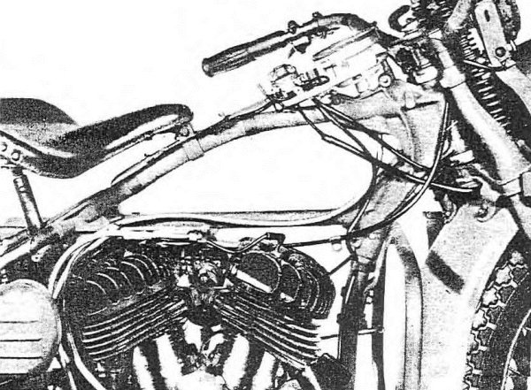
117. HORN.
a. Description. Horn is mounted to headlight bracket by means of four bolts, lock washers, and nuts. One horn terminal is connected with operating button, and other terminal is connected to No. 4 ignition and light switch terminal (fig. 73).
a. Description. The horn is attached to the headlight bracket using four bolts, lock washers, and nuts. One terminal of the horn is linked to the operating button, while the other terminal is connected to terminal No. 4 of the ignition and light switch (fig. 73).
b. Adjust. Tone adjusting screw is located in rear side of horn. If horn fails to operate and moving the adjusting screw does not remedy the trouble, horn must be replaced. NOTE: Do not change position of the adjusting screw located in center of diaphragm.
b. Adjust. The tone adjusting screw is found on the back side of the horn. If the horn doesn't work and adjusting the screw doesn't fix the issue, you'll need to replace the horn. NOTE: Do not change the position of the adjusting screw located in the center of the diaphragm.
118. WIRING.
a. Cable System. Since ignition and lights are controlled by the ignition and light switch, all wires terminate at the ignition and light switch. Cables for wire protection are used, making it necessary to replace cables rather than individual wires. A study of figure 73 will be helpful when removing or installing any of the wiring cables. Also study figures 78 and 79 and note how cables are arranged on frame, and how they lead to the switch panel.
a. Cable System. Since the ignition and lights are controlled by the ignition and light switch, all wires connect at that switch. Protective cables are used, so you'll need to replace the entire cable instead of just individual wires. Reviewing figure 73 will be useful when taking out or installing any of the wiring cables. Also, take a look at figures 78 and 79 to see how the cables are set up on the frame and how they connect to the switch panel.
Section 24
Dashboard
| Below is a short piece of text (5 words or fewer). Modernize it into contemporary English if there's enough context, but do not add or omit any information. If context is insufficient, return it unchanged. Do not add commentary, and do not modify any placeholders. If you see placeholders of the form __A_TAG_PLACEHOLDER_x__, you must keep them exactly as-is so they can be replaced with links. | |
|---|---|
| Panel cover | 119 |
| Indicator lights | 120 |
| Speedometer head | 121 |
119. PANEL COVER (fig. 80).
a. Remove. Remove speedometer light switch knob and remove screw. Remove hexagon‐head screw on front of cover. Remove two screws from side of cover. Remove two screws and washers which fasten plate to right side of cover. Lift cover off panel.
a. Remove. Take off the speedometer light switch knob and unscrew it. Remove the hexagon-head screw at the front of the cover. Take out the two screws on the side of the cover. Remove the two screws and washers that attach the plate to the right side of the cover. Lift the cover off the panel.

b. Install. Position cover on panel. Install two side mounting screws and washers and install hexagon‐head screw, plain washer, and lock washer in front end of cover. Attach cover side plate, installing two screws and washers. Install speedometer light switch knob and screw.
b. Install. Place the cover on the panel. Put in two side mounting screws and washers, then install the hexagon-head screw, plain washer, and lock washer at the front end of the cover. Attach the cover's side plate by installing two screws and washers. Finally, install the speedometer light switch knob and screw.
120. INDICATOR LIGHTS.
a. Three 2–c.p. single‐contact lamps are located on instrument panel. One for oil pressure (red) indicator light: one for generator‐charge192 (green) indicator light, and one for speedometer illumination.
a. Three 2–c.p. single-contact lamps are on the instrument panel. One is for the oil pressure (red) indicator light; one is for the generator charge 192 (green) indicator light, and one is for illuminating the speedometer.
b. Remove and/or Install. Remove and/or install panel cover (par. 119).
b. Remove and/or Install. Take off and/or put on the panel cover (par. 119).
c. Test Generator‐Charge (Green) Indicator Lamp. Disconnect black wire from relay terminal (top terminal at front end of relay) and ground on relay base. Turn ignition and light switch on. Lamp should light. If it does not light, check wire for condition and/or replace lamp after removing panel cover (par. 119).
c. Test Generator-Charge (Green) Indicator Lamp. Disconnect the black wire from the relay terminal (the top terminal at the front end of the relay) and ground it on the relay base. Turn on the ignition and light switch. The lamp should light up. If it doesn’t, check the wire for damage and/or replace the lamp after removing the panel cover (par. 119).
d. Test Oil Pressure (Red) Indicator Lamp. Disconnect wire from oil pressure switch. Ground the wire on engine. Turn ignition and light switch on. Lamp should light. If it does not light, check wire for condition and/or replace lamp after removing panel cover (par. 119). If lamp and wiring are satisfactory, replace oil pressure switch.
d. Test Oil Pressure (Red) Indicator Lamp. Disconnect the wire from the oil pressure switch. Ground the wire on the engine. Turn on the ignition and the light switch. The lamp should light up. If it doesn't light, check the wire for any issues and/or replace the lamp after removing the panel cover (par. 119). If the lamp and wiring are in good condition, replace the oil pressure switch.
121. SPEEDOMETER HEAD.
a. Remove. Remove instrument panel cover (par. 119). Loosen the two tank front mounting bolts and remove rear mounting bolt to free speedometer cable clamp. Disconnect speedometer cable at drive unit. Free cable from clip located below tool box. Remove two screws which mount head to frame. Pull head upward, working cable forward under tank, until head and cable connection nut is clear of frame. Unscrew cable nut. NOTE: Cable may be secured to frame tube, between tanks, with friction tape. If so, cut tape.
a. Remove. Take off the instrument panel cover (par. 119). Loosen the two front mounting bolts on the tank and remove the rear mounting bolt to free the speedometer cable clamp. Disconnect the speedometer cable at the drive unit. Free the cable from the clip located below the toolbox. Remove the two screws that attach the head to the frame. Pull the head upward, guiding the cable forward under the tank, until the head and cable connection nut are clear of the frame. Unscrew the cable nut. NOTE: The cable may be secured to the frame tube, between the tanks, with friction tape. If that's the case, cut the tape.
b. Install. Attach speedometer head to cable end and tighten nut. Pass cable down into frame hole, pulling on rear of cable at same time. Mount speedometer head to frame with two screws and lock washers. Install panel cover (par. 119). Secure cable clamp under head of tank rear mounting bolt. Secure cable in clip, located under tool box. Attach end of cable to drive unit. Tighten the two tank front mounting bolts.
b. Install. Connect the speedometer head to the end of the cable and tighten the nut. Feed the cable down into the frame hole while pulling on the back of the cable at the same time. Attach the speedometer head to the frame with two screws and lock washers. Install the panel cover (par. 119). Secure the cable clamp under the head of the rear tank mounting bolt. Fasten the cable in the clip located under the toolbox. Connect the end of the cable to the drive unit. Tighten the two front tank mounting bolts.
Section 25
Tires, wheels, and hubs
| Paragraph | |
|---|---|
| Description | 122 |
| Tires | 123 |
| Rims and spokes | 124 |
| Front wheel replacement | 125 |
| Front wheel hub adjustment | 126 |
| Rear wheel replacement | 127 |
122. DESCRIPTION.
a. Wheels have drop center rims to accommodate 4.00 x 18 tires. Front and rear wheels are not interchangeable. Front wheel hub is of ball‐bearing design, having cone adjustment similar to that of a bicycle hub. Rear wheel hub is of roller‐bearing design and must be taken apart for adjustment. Both wheels have “knock‐out” type axles.
a. Wheels have drop center rims to fit 4.00 x 18 tires. The front and rear wheels are not interchangeable. The front wheel hub uses ball bearings and has a cone adjustment similar to a bicycle hub. The rear wheel hub uses roller bearings and needs to be disassembled for adjustments. Both wheels have “knock‐out” type axles.
123. TIRES.
a. Description. Wheel rims are of the drop‐center type, having a depression, or well, in center of rim. The rim well, being smaller in circumference than the rest of the rim, allows one casing bead to fit loosely in it while other bead is being worked over edge of rim. Bear in mind the importance of keeping one bead in rim well while other bead is being worked onto or off rim. NOTE: It is not always necessary to completely remove casing from rim. Removing one side only allows inner tube to be removed and reinstalled, and also allows inside of casing to be inspected.
a. Description. Wheel rims are of the drop-center type, featuring a depression, or well, in the center of the rim. The rim well, being smaller in circumference than the rest of the rim, allows one casing bead to fit loosely in it while the other bead is being worked over the edge of the rim. Keep in mind the importance of keeping one bead in the rim well while the other bead is being worked onto or off the rim. NOTE: It's not always necessary to completely remove the casing from the rim. Removing one side only allows the inner tube to be taken out and reinstalled, and it also allows for an inspection of the inside of the casing.
b. Remove.
b. Delete.
(2) Remove valve cap and valve core to free all air from tube.
(2) Take off the valve cap and valve core to release all the air from the tube.
(3) Press casing head into rim well to within a short distance of each side of valve.
(3) Push the casing head into the rim well, leaving a small gap on each side of the valve.
(4) Using tire iron “B” in vehicle kit (fig. 11), start bead over edge of rim at valve. Do not use force when starting bead over edge of rim with tire iron, because bead wires may be broken or stretched, and tire ruined. With first bead in rim well, bead on other side can be started easily over edge of rim. After a portion of second bead is started over rim edge, casing can be further removed from wheel without aid of tire iron.
(4) Using tire iron “B” from the vehicle kit (fig. 11), start putting the bead over the edge of the rim at the valve. Don’t force the bead over the edge of the rim with the tire iron, as this could break or stretch the bead wires and ruin the tire. Once the first bead is properly seated in the rim, you can easily start the bead on the other side over the edge of the rim. After a section of the second bead is started over the rim edge, you can remove the casing from the wheel further without needing the tire iron.

RA PD 310254
Figure 81—Disassembly for Front Wheel Removal
RA PD 310254
Figure 81—Taking Apart for Front Wheel Removal
c. Install. Before applying casing to rim, see that rubber rim strip is in place in rim well and that rim strip valve hole alines with valve hole in rim.
c. Install. Before putting the casing on the rim, make sure the rubber rim strip is in place in the rim well and that the valve hole in the rim strip lines up with the valve hole in the rim.
(1) Start either bead of casing over rim edge. Work around wheel until entire bead is on rim.
(1) Start one bead of the tire over the rim edge. Go around the wheel until the entire bead is on the rim.
(2) Place inner tube in casing. NOTE: Inner tube may be placed in casing before or after first bead of casing is on rim. Insert valve stem through hole in rim and start valve stem lock nut. While pressing first bead into rim well, work remaining bead over edge of rim, starting directly opposite valve stem. Work both ways around wheel toward valve.
(2) Put the inner tube inside the casing. NOTE: You can put the inner tube in the casing either before or after the first bead of the casing is on the rim. Push the valve stem through the hole in the rim and begin threading the valve stem lock nut. While pushing the first bead into the rim well, maneuver the remaining bead over the edge of the rim, starting directly across from the valve stem. Work your way around the wheel toward the valve.
(3) Inflate front tire to 18 pounds, and rear tire to 20 pounds.
(3) Inflate the front tire to 18 psi and the rear tire to 20 psi.
124. RIMS AND SPOKES.
a. Wheels with broken and or missing spokes, with rims in badly kinked and or distorted condition, or having considerable run‐out, must be replaced.
a. Wheels with broken or missing spokes, rims that are badly bent or warped, or those that have significant wobble, must be replaced.
b. Loose wheel spokes must be tightened evenly, being careful not to distort rim out‐of‐round or cause run‐out. Use spoke nipple wrench (41–W–3339) for front wheel spokes, and wrench (41–W–3340) for rear wheel spokes.
b. Loose wheel spokes need to be tightened evenly, making sure not to distort the rim or cause any wobbling. Use the spoke nipple wrench (41–W–3339) for the front wheel spokes, and the wrench (41–W–3340) for the rear wheel spokes.
125. FRONT WHEEL REPLACEMENT (fig. 81).
a. Remove.
Delete.
(1) Support vehicle on rear stand. Raise front end of vehicle by blocking up under frame loop on skid plate.
(1) Support the vehicle on a rear stand. Lift the front end of the vehicle by placing blocks under the frame loop on the skid plate.
(2) Remove brake shackle bolt from rigid fork on left side of vehicle.
(2) Take out the brake shackle bolt from the rigid fork on the left side of the vehicle.
(3) Front axle is knock‐out type. Remove cotter pin and axle castle nut and pull out axle. Wheel is free for removal. CAUTION: Before removing axle note how slot in brake stabilizer plate is fitted over the extended (button) end of the left‐front rocker plate stud. It is necessary that this be correctly assembled when replacing front wheel.
(3) The front axle is a knock-out type. Remove the cotter pin and the axle castle nut, then pull out the axle. The wheel is now free for removal. CAUTION: Before removing the axle, take note of how the slot in the brake stabilizer plate fits over the extended (button) end of the left-front rocker plate stud. It's important that this is reassembled correctly when putting the front wheel back on.
(4) Roll wheel forward and remove brake assembly from brake drum, leaving the assembly attached to brake control wire and control wire housing.
(4) Roll the wheel forward and take off the brake assembly from the brake drum, keeping it connected to the brake control wire and control wire housing.
b. Install (fig. 81). NOTE: At the time wheel and brake assembly is located in front fork, and before axle is installed, make sure that the curved slot in brake stabilizer plate engages with the button end of the left‐front rocker plate stud.
b. Install (fig. 81). NOTE: When the wheel and brake assembly is positioned in the front fork, and before the axle is put in, ensure that the curved slot in the brake stabilizer plate fits over the button end of the left-front rocker plate stud.
(1) Install brake assembly in brake drum.
(1) Put the brake assembly in the brake drum.
(2) Roll wheel into position. Engage stabilizer plate notch and rocker plate stud button end, and at same time insert front axle.
(2) Roll the wheel into place. Lock the stabilizer plate notch and the rocker plate stud button end, and at the same time, insert the front axle.
(3) Install castle nut (no lock washer used) on axle and securely tighten.
(3) Install the castle nut (no lock washer needed) on the axle and tighten it securely.

RA PD 310252
Figure 82—Front Hub Prepared for Cone Adjustment
RA PD 310252
Figure 82—Front Hub Ready for Cone Adjustment
(4) Use good cotter pin to secure nut.
(4) Use a good cotter pin to secure the nut.
(5) Install brake shackle bolt and special lock washer and nut. Tighten nut.
(5) Install the brake shackle bolt along with the special lock washer and nut. Tighten the nut.
(6) Check front brake control wire and housing to make sure everything is in order and correctly adjusted (par. 97).
(6) Check the front brake control wire and housing to ensure everything is in order and properly adjusted (par. 97).
(7) Remove blocking from under vehicle.
(7) Take out any blocks from under the vehicle.
126. FRONT WHEEL HUB ADJUSTMENT.
a. Front wheel, ball‐bearing hub, is similar to a bicycle front hub as far as adjustment is concerned. Do not completely disassemble hub for adjustment as balls are not in retainers, and will fall out when cone is removed. Hub is provided with grease deflector sleeve and felt retainer. NOTE: Earlier models are not equipped with grease deflector sleeve or felt retainer washer. Front wheel should have slight play or shake on bearings, and should turn freely.
a. The front wheel with a ball-bearing hub is similar to a bicycle front hub regarding adjustments. Do not take the hub apart completely for adjustments since the balls are not held in place and will fall out when the cone is removed. The hub comes with a grease deflector sleeve and a felt retainer. NOTE: Earlier models do not have a grease deflector sleeve or a felt retainer washer. The front wheel should have a little play or shake in the bearings and should turn smoothly.

RA PD 315733
Figure 83—Disassembly for Rear Wheel Removal
RA PD 315733
Figure 83—Taking Apart for Rear Wheel Removal
(2) Back off cone lock nut to end of axle sleeve. Do not remove nut.
(2) Loosen the cone lock nut until it reaches the end of the axle sleeve. Do not take the nut off.
(3) Turn cone on axle sleeve to the right (clockwise) to take up wheel play, and to the left (counterclockwise) to give more wheel play. Adjust so that wheel has slight play on bearing.
(3) Turn the cone on the axle sleeve to the right (clockwise) to tighten the wheel play, and to the left (counterclockwise) to loosen the wheel play. Adjust it so that the wheel has a little play on the bearing.
(4) Tighten cone lock nut. After tightening nut, again try for slight wheel play on bearing. Sometimes tightening lock nut takes up on bearing play. If necessary, readjust for desired results when cone lock nut is tight.
(4) Tighten the cone lock nut. After tightening the nut, check for a slight wheel play on the bearing again. Sometimes, tightening the lock nut reduces bearing play. If needed, readjust to achieve the desired results when the cone lock nut is tight.
(5) Install front wheel and brake assembly (par. 125).
(5) Install the front wheel and brake assembly (par. 125).
(6) Check adjustment of front brake.
(6) Check the adjustment of the front brake.
127. REAR WHEEL REPLACEMENT (figs. 83 and 84).
a. Remove.
a. Delete.
(1) Support vehicle on rear stand.
(1) Support the vehicle on the rear stand.
(2) Release mudguard rear stays. Loosen mounting nuts, and raise end of mudguard for wheel clearance.
(2) Release the rear stays of the mudguard. Loosen the mounting nuts and lift the end of the mudguard for wheel clearance.

(3) Remove the five wheel mounting socket screws which secure wheel hub to brake shell and sprocket assembly. Use vehicle kit wrench “S” and sleeve (handle) “C” (fig. 11). NOTE: Wrench can be inserted from left side through holes in hub, and wheel must be turned to bring each mounting screw directly to the rear of axle for accessibility.
(3) Take out the five screws that mount the wheel socket and hold the wheel hub to the brake shell and sprocket assembly. Use the vehicle kit wrench “S” and sleeve (handle) “C” (fig. 11). NOTE: You can insert the wrench from the left side through the holes in the hub, and you need to turn the wheel to align each mounting screw directly behind the axle for easy access.
(5) Remove axle nut (right side of vehicle), using vehicle kit wrench “J” (fig. 11).
(5) Take off the axle nut (right side of the vehicle) using the vehicle kit wrench “J” (fig. 11).
(6) Pull out axle from left side of vehicle.
(6) Remove the axle from the left side of the vehicle.
(7) Remove spacer from between wheel hub end and left side of frame.
(7) Take out the spacer between the wheel hub end and the left side of the frame.
(8) Wheel is now free to come out by pulling and working it away from dowel pins located in brake shell assembly. A wheel being removed for the first time may offer some resistance. It will be observed that chain, sprocket, and brake assembly remain in the vehicle frame.
(8) The wheel can now be pulled out by working it away from the dowel pins in the brake shell assembly. If the wheel is being removed for the first time, it may resist a bit. You'll notice that the chain, sprocket, and brake assembly stay in the vehicle frame.
b. Install (figs. __A_TAG_PLACEHOLDER_0__ and __A_TAG_PLACEHOLDER_1__).
(1) Position wheel on brake shell dowel pins. Work hub onto dowels as far as it will go.
(1) Align the wheel with the brake shell dowel pins. Push the hub onto the dowels as far as it can go.
(2) Install axle spacer at left end of hub so that axle will pass through it and the hub.
(2) Install the axle spacer at the left end of the hub so that the axle can pass through it and the hub.
(3) Install axle from left side of vehicle. Pass it through sleeve and hub, with end of axle engaging the frame left axle clip notch.
(3) Install the axle from the left side of the vehicle. Slide it through the sleeve and hub, making sure the end of the axle fits into the left axle clip notch on the frame.
(4) See that lock washer is in place. Turn on and securely tighten axle nut, using vehicle kit wrench “J” (fig. 11).
(4) Make sure that the lock washer is in place. Turn on and securely tighten the axle nut using the vehicle kit wrench “J” (fig. 11).
(5) Loosen wing nut clamping brake rod lock. Move brake rod lock forward so that it will not strike any object when brake is operated; tighten wing nut to retain in position (fig. 84).
(5) Loosen the wing nut that secures the brake rod lock. Move the brake rod lock forward to ensure it won't hit anything when the brake is engaged; tighten the wing nut to hold it in place (fig. 84).
(6) Install and securely tighten the five wheel mounting socket screws.
(6) Install and firmly tighten the five wheel mounting socket screws.
(7) Lower mudguard into position and attach ends of rear stays. Securely tighten the clamping nuts.
(7) Lower the mudguard into place and connect the ends of the rear stays. Tighten the clamping nuts securely.
REFERENCES
| STANDARD NOMENCLATURE LISTS | ||
|---|---|---|
Motorcycle, chain drive (Harley‐Davidson) Chain-driven motorcycle (Harley-Davidson) |
SNL G–523 | |
Cleaning, preserving and lubricating materials, recoil fluids, special oils, and miscellaneous related items Cleaning, preserving, and lubricating materials, recoil fluids, special oils, and various related items |
SNL K–1 | |
Soldering, brazing, and welding materials, gases, and related items Soldering, brazing, and welding supplies, gases, and related items |
SNL K–2 | |
Tools, maintenance, for the repair of automotive vehicles Tools, maintenance, for the repair of cars |
SNL G–27 | |
Tool sets—motor transport Tool kits—transportation |
SNL N–19 | |
Tool sets for ordnance service command, automotive shops Tool sets for artillery service command, auto repair shops |
SNL N–30 | |
Current Standard Nomenclature Lists are listed above. Current Standard Nomenclature Lists are provided above. |
||
An up‐to‐date list of SNL’s is maintained in the Index to Maintenance Publications An updated list of SNLs is kept in the Index to Maintenance Publications. |
OFSB 1–1 | |
| EXPLANATORY PUBLICATIONS | ||
Military motor vehicles Military vehicles |
AR 850–15 | |
| Automotive Materiel | ||
Automotive electricity Car electronics |
TM 10–580 | |
Electric fundamentals Electric basics |
TM 10–455 | |
The motor vehicle The car |
TM 10–510 | |
Chassis, body, and trailer units Chassis, body, and trailer parts |
TM 10–550 | |
| Maintenance and Repair | ||
Automotive lubrication Car oiling |
TM 10–540 | |
Motor transport inspections Vehicle inspections |
TM 10–545 | |
Tire repair and retread Tire repair and retreading |
TM 9–1868 | |
Cleaning, preserving, lubricating and welding materials and similar items issued by the ordnance Cleaning, preserving, lubricating, and welding materials and similar items provided by the ordnance |
TM 9–850 | |
Detailed lubrication instructions for ordnance materiel Detailed lubrication instructions for weapons equipment |
OFSB 6–series | |
| Protection of Materiel | ||
Explosives and demolitions Explosives and demolition |
FM 5–25 | |
Defense against chemical attack Defense against chemical warfare |
FM 21–40 | |
Decontamination of Armored Force vehicles Cleaning Armored Force vehicles |
FM 17–59 | |
Chemical decontamination, materials and equipment Chemical decontamination, supplies and gear |
TM 3–220 | |
| List of Publications for Training | FM 21–6 | |
| Storage and Shipment | ||
Registration of motor vehicles Vehicle registration |
AR 850–10 | |
Storage of motor vehicle equipment Vehicle equipment storage |
AR 850–18 | |
Ordnance storage and shipment chart, group G—Major items Ordnance storage and shipping chart, group G—Key items |
OSSC–G | |
INDEX
- APage No.
- Air cleaner, 122
- Allocation of maintenance by echelons, 40
- Ammunition box carrier, 169
- Armature bearing special lubrication, 145
- Auxiliary brake, 12
- B
- Battery, lighting system, horn
- battery
- check electrolyte level, 181
- installation, 185
- removal, 181
- description, 181
- horn
- adjustment, 190
- description, 190
- ignition and light switch
- installation, 188
- removal, 188
- service headlights
- adjustment, 185
- blackout, 186
- marker, 187
- taillights
- blackout stop and taillight, 187
- service stop and taillight, 187
- wiring
- cable system, 190
- removal and installation, 190
- Brake system
- brake shoe installation, 151
- brake shoe removal, 150
- front wheel brake, 151
- rear wheel brake
- adjustment, 149
- linkage, 149
- C
- Carburetor
- adjustment, 116
- bowl cleaning, 120
- installation, 118
- removal, 118
- Chains and sprockets
- chain oilers, 109
- chain repair tool, 113
- countershaft sprocket replacement, 114
- engine sprocket replacement, 113
- front chain adjustment, 105
- front chain replacement, 111
- rear chain adjustment, 107
- rear chain replacement, 111
- rear wheel alinement, 107
- Clutch
- control adjustment, 85
- description, 86
- disk and spring inspection, 91
- disk installation, 93
- disk removal, 90
- maintenance and adjustment, 86
- release bearing
- installation, 95
- removal, 95
- spring tension adjustment, 89
- Controls and operation
- controls
- auxiliary brake (front wheel), 12
- carburetor choke, 13
- clutch, 10
- foot starter crank, 12
- gasoline valve, 9
- gear shifter, 12
- ignition and light switch, 12
- instrument panel signal lights, 13
- service brake (rear wheel), 12
- spark, 10
- steering damper, 12
- throttle, 10
- driving precautions
- avoid low gear operation, 17
- braking, 17
- high‐speed tips, 17
- engine prestarting instructions, 13
- operation of vehicle
- starting on level ground, 16
- starting on uneven or soft ground, 16
- running‐in new engine (or vehicle), 19
- starting engine
- behavior of instrument panel signal lights, 15
- cold engine, 14
- engine with dead battery, 15
- hot engine, 15
- warm engine, 14
- stopping and parking vehicle
- parking vehicle, 18
- stopping vehicle, 17
- 202 stopping the engine, 16
- towing vehicle to start engine
- engine starting with dead battery, 18
- D
- Data, tabulated
- engine, 72
- vehicle specifications, 7
- capacities, 8
- performance, 7
- Description
- battery, lighting system, horn, 181
- clutch, 86
- engine, 72
- generating system, 142
- ignition system, 129
- intake and exhaust system, 122
- tires, wheels and hubs, 193
- transmission, 96
- Description of vehicle, 7
- E
- Echelon system of maintenance allocation, 40
- Engine
- carbon removal, 74
- data, 72
- description, 72
- head, gasket replacement
- installation, 74
- removal, 73
- installation, 82
- oil feed pump replacement, 77
- removal, 78
- tune‐up, 72
- valve tappet adjustment, 74
- Exhaust system, 126
- F
- First echelon preventive maintenance services
- after‐operation and weekly service, 25
- at‐halt service, 24
- before‐operation service, 21
- during‐operation service, 23
- purpose, 20
- Fuel system
- carburetor
- installation, 118
- removal, 118
- carburetor adjustment
- complete readjustment of carburetor, 116
- low speed adjusting needle, 116
- carburetor bowl cleaning, 120
- fuel pipe
- installation, 121
- removal, 121
- fuel strainer
- cleaning, 120
- install strainer assembly, 120
- remove strainer assembly, 120
- general, 115
- throttle control wire adjustment
- closed throttle, 118
- open throttle, 118
- G
- Generating system
- armature bearing special lubrication, 145
- commutator cleaning, 143
- cut‐out relay, 147
- description, 142
- generator installation, 147
- generator removal, 145
- Generator removal and installation, 145, 147
- H
- Horn, 190
- I
- Ignition system
- circuit breaker and timer assembly installation, 133
- recommended recheck of ignition timing, 135
- removal, 133
- circuit breaker points
- adjustable contact point installation, 131
- adjustable contact point removal, 131
- adjustment, 131
- 203 breaker lever installation, 131
- breaker lever removal, 130
- coil to timer wire
- installation, 138
- removal, 138
- condenser
- installation, 133
- removal, 131
- description, 129
- spark coil
- installation, 140
- removal, 139
- spark control adjustment, 139
- spark plugs
- cleaning, 129
- point adjustment, 129
- replacement, 129
- type, 129
- Installation procedure
- air cleaner, 126
- ammunition box carrier, 169
- battery, 185
- battery box, 173
- carburetor, 118
- circuit breaker and timer assembly, 133
- circuit breaker lever, 131
- circuit breaker points, 131
- clutch release bearing, 95
- coil to timer wire, 138
- condenser, 133
- control wire housings, 166
- engine, 82
- engine head gasket, 74
- exhaust pipe, 127
- foot starter, 98
- fork assembly, 158
- front wheel, 196
- fuel pipe, 121
- fuel strainer assembly, 120
- fuel tank, 175
- generator, 147
- handle bar assembly, 163
- ignition and light switch, 188
- instrument panel cover, 191
- jiffy stand, 177
- luggage carrier, 170
- mudguards, 171
- muffler assembly, 127
- oil tank, 176
- outer front chain guard, 167
- rear chain guard, 169
- rear stand, 176
- rear wheel, 199
- saddle post, 178
- safety guards, 178
- scabbard carrier, 169
- skid plates, 180
- spark coil, 140
- spark control wire, 166
- speedometer, 192
- spring forks, 154
- starter crank springs, 101
- steering damper, 161
- throttle control wire, 165
- tires, 195
- tool box and bracket assembly, 173
- upper bumper springs, 155
- upper coil springs, 155
- wiring, 190
- Instrument panel
- indicator lights, 191
- panel cover
- installation, 191
- removal, 191
- speedometer
- installation, 192
- removal, 192
- Intake and exhaust system
- air cleaner
- general, 122
- installation, 126
- maintenance, 123
- removal, 125
- service, 122
- air cleaner mounting bracket replacement, 126
- description
- exhaust, 122
- intake, 122
- exhaust system
- muffler assembly installation, 127
- muffler assembly removal, 126
- pipe installation, 127
- hose and carburetor fitting
- installation, 125
- removal, 125
- Introduction
- scope of manual, 3
- supersession of quartermaster manuals, 3
- 204 L
- Lighting system, 181
- Lubrication
- introduction, 30
- lubrication guide, 30
- general, 30
- lubrication notes, 30
- oilcan points, 34
- supplies, 30
- warning light, 34
- M
- Maintenance allocation
- allocation of maintenance by echelons
- clutch, 40
- controls and linkage, 40
- electrical group, 41
- engine (V‐45″ twin engine), 41
- exhaust group, 42
- miscellaneous, 42
- suspension (front), 43
- suspension (rear), 43
- tires, 44
- transmission, 44
- vehicle assembly, 44
- scope of maintenance, 39
- Manual, scope of, 3
- O
- Organization tools and equipment, 60
- P
- Preventive maintenance services
- first echelon, 20
- second echelon, 45
- R
- References
- explanatory publications
- automotive materiel, 200
- list of publications for training, 200
- maintenance and repair, 200
- protection of materiel, 200
- storage and shipment, 200
- standard nomenclature lists, 200
- Removal procedure
- air cleaner, 125
- ammunition box carrier, 169
- battery, 181
- battery box, 172
- carbon, 74
- carburetor, 118
- circuit breaker and timer assembly, 133
- circuit breaker lever, 130
- condenser, 131
- control wire housings, 166
- engine, 78
- engine head gasket, 73
- foot starter, 98
- fork assembly, 155
- front wheel, 195
- fuel pipe, 121
- fuel strainer assembly, 120
- fuel tank, 174
- generator, 145
- handle bar assembly, 162
- ignition coil to timer wire, 138
- instrument panel cover, 191
- jiffy stand, 176
- luggage carrier, 170
- mudguards, 170, 171
- muffler assembly, 126
- oil tank, 175
- outer front chain guard, 167
- rear chain guard, 169
- rear stand, 176
- rear wheel, 198
- release bearing (clutch), 95
- saddle post, 178
- safety guards, 178
- scabbard carrier, 169
- skid plates, 180
- spark coil, 139
- spark control wire, 166
- speedometer, 192
- spring forks, 154
- starter crank spring, 98
- steering damper, 161
- throttle control wire, 164
- tires, 193
- tool box and bracket assembly, 173
- upper bumper springs, 155
- upper coil springs, 155
- Road test chart of maintenance operations, 49
- 205 S
- Second echelon preventive maintenance
- road test chart, 47
- maintenance operation, 49
- services
- first echelon participation, 45
- frequency, 45
- general procedures, 45
- specific procedures, 47
- Sheet metal and equipment
- battery box
- installation, 173
- removal, 172
- carriers
- ammunition box carrier installation, 169
- ammunition box carrier removal, 169
- fuel tank
- installation, 175
- removal, 174
- chain guards
- outer front chain guard installation, 167
- outer front chain guard removal, 167
- rear chain guard installation, 169
- rear chain guard removal, 169
- jiffy stand
- installation, 177
- removal, 176
- luggage carrier
- installation, 170
- removal, 170
- mudguard (front)
- installation, 171
- removal, 170
- mudguard (rear)
- installation, 171
- removal, 171
- oil tank
- installation, 176
- removal, 175
- rear stand
- installation, 176
- removal, 176
- saddle post
- description, 178
- installation, 178
- removal, 178
- safety guards
- installation, 178
- removal, 178
- scabbard carrier
- installation, 169
- removal, 169
- skid plates
- installation, 180
- removal, 180
- tanks
- fuel tank, 173
- general, 173
- oil tank, 173
- tool box
- box and bracket assembly installation, 173
- box and bracket assembly removal, 173
- Spark plugs, 129
- Speedometer
- installation, 192
- removal, 192
- Steering control
- control wire housings
- installation, 166
- removal, 166
- fork assembly (complete)
- installation, 158
- removal, 155
- rocker plate studs, 160
- forks (springs)
- installation, 154
- removal, 154
- handle bar controls
- install throttle control wire, 165
- remove throttle control wire, 164
- handle bars
- installation of assembly, 163
- removal of assembly, 162
- spark control wire
- installation, 166
- removal, 166
- steering damper
- installation, 161
- removal, 161
- upper coil springs and upper bumper springs
- installation, 155
- removal, 155
- 206 Stowage on vehicle (tools and equipment), 35
- T
- Tabulated data
- engine, 72
- vehicle specifications, 7
- capacities, 8
- performance, 7
- Tires, wheels, and hubs
- description, 193
- front wheel
- hub adjustment, 197
- installation, 196
- removal, 195
- rear wheel
- installation, 199
- removal, 198
- rims and spokes, 195
- tires
- description, 193
- installation, 195
- removal, 193
- Tools and equipment stowage on the vehicle
- vehicle equipment, 36
- vehicle spare parts, 38
- vehicle tools, 35
- Transmission
- control linkage
- adjustment, 97
- checking gear shifter control linkage, 96
- transmission shifted to adjust front drive chain, 96
- description, 96
- foot starter
- installation, 98
- removal, 98
- installation, 101
- removal, 99
- starter crank springs
- installation, 98
- removal, 98
- Trouble shooting
- brakes, 70
- electrical system, 68
- engine
- instruction, 61
- tests to determine mechanical condition, 63
- engine lubricating system, 64
- fuel system, 65
- generating system, 68
- ignition system, 66
- introduction, 61
- steering, 71
- transmission and clutch, 69
- wheels and chains, 69
- W
- Wheels and hubs, 195
- Wiring, 190
[A.G. 300.7 (17 Aug. 1943)]
[A.G. 300.7 (Aug 17, 1943)]
By order of the Secretary of War:
G. C. MARSHALL,
Chief of Staff.
By order of the Secretary of Defense:
G.C. Marshall
Chief of Staff
Official:
J. A. ULIO,
Major General,
The Adjutant General.
Officially:
J.A. ULIO,
Major General
The Adjutant General.
Distribution: R9 (4): IR 5, 7 and 17 (5): Bn 9 (2): IBn 5, 6,
7 and 17 (5): C9 (8): IC 5, 6, 7 and 17 (5)
Distribution: R9 (4): IR 5, 7 and 17 (5): Bn 9 (2): IBn 5, 6,
7 and 17 (5): C9 (8): IC 5, 6, 7 and 17 (5)
(For explanation of symbols, see FM 21–6)
(For explanation of symbols, see FM 21–6)
RAPD3OEC43–81M
RAPD3OEC43–81M
PUBLICATIONS DEPARTMENT ‐ RARITAN ARSENAL
PUBLICATIONS DEPARTMENT ‐ RARITAN ARSENAL
Transcriber’s notes:
Transcription notes:
The original spelling, punctuation and hyphenation has been retained except for apparent printer’s errors which have been silently corrected.
The original spelling, punctuation, and hyphenation have been kept the same except for obvious printing mistakes that have been quietly fixed.
In the Fig. 51 caption M—MARK ON BREAKER CAM AND MARKS ON TIMER HEAD AND HAND - ‘HAND’ should possibly read ‘BAND’.
In the Fig. 51 caption M—MARK ON BREAKER CAM AND MARKS ON TIMER HEAD AND HAND - ‘HAND’ should probably read ‘BAND’.
In the echelon table, section 25. ALLOCATION OF MAINTENANCE, ‘strained gasoline’ should possibly read ‘strainer gasoline’.
In the echelon table, section 25. ALLOCATION OF MAINTENANCE, ‘strained gasoline’ should probably read ‘strainer gasoline’.
Download ePUB
If you like this ebook, consider a donation!